Embed Size (px)
Citation preview
BALANCING LOW NOx BURNER AIR FLOWSTHROUGH THE USE OF
INDIVIDUAL BURNER AIRFLOW MONITORS
By
Scott A. Vierstra, P.E.Senior Engineer, American Electric Power Service Corporation
and
Dave EarleySales Manager, Power Products Division
AMC Power
for
POWER-GEN INTERNATIONAL1998 CONFERENCE
December 9-11Orlando, Florida USA
BackgroundIn response to the 1990 Clean Air Act Amendments and the subsequent NOx compliance rules,utilities have been retrofitting low NOx firing systems on their existing fossil fired boilers. Forthe majority of these units which were built prior to the implementation of the New SourcePerformance Standards (NSPS), the original burner designs were intentionally turbulent andencouraged rapid mixing between the combustion air and fuel streams both for individualburners and between adjacent burners flows. Under these operating design parameters it was notparticularly critical that the fuel and combustion air flow balance between burners be measured,controlled or maintained since satisfactory mixing was quickly achieved within the combustionzone.
Most if not all of the commercial low NOx burner systems, with an emphasis on those for walland down fired boilers, were initially designed, developed and tested either in single burner testfacilities or through the use of computational fluid dynamic (CFD) modeling. In either case theability to control design sensitive flow ratios, the fluid dynamics and, hence, the combustionprocess was well maintained. Thus, either through testing in a single burner test facility ortheoretically through CFD modeling, the burners were optimized in an attempt to provide themost competitive design, both in terms of cost and performance. The resultant products, moreoften than not, have incorporated multiple dynamic control devices per burner, such as shroudsor discs to regulate flow and registers or vanes to control zonal flow proportions and swirl.However, all of these variables and there control devices are interdependent. Therefor, as firingsystems are expanded beyond a single burner configuration, the ability to operate the equipmentunder the optimal design conditions becomes increasingly more difficult. In reality, thedeviations between the field and design conditions can produce such varied dynamic conditionsbetween burners that the operational and performance sensitivities experienced in the singleburner facility and through CFD modeling become difficult to measure. No longer can onevariable be changed uniformly amongst all the burners to measure its impact, in part, because italso impacts the other dependent variables but mostly because the system does not start with abalanced set of conditions between burners. Some field experiences have shown that the lowNOx systems, once installed, have experienced less than desirable sensitivity to optimizationefforts. The burner conditions are so difficult to balance that the combustion process is toomuddy to differentiate change and readily achieve improvements.
While limitations in reproducing design conditions in the field applications of low NOx systemsmay not be a significant issue for some utilities in meeting Title IV NOx compliance, future ruleconsiderations which will likely force the utilization of post combustion ammonia basedtechnologies will significantly add economic benefit to the ability to achieve and maintain trueNOx emission optimization on the combustion side through potentially SCR or SNCR capitaland reagent cost avoidance. This paper discusses the development and application of at least onecontrol component, individual burner air flow monitors, IBAMs,` to assist in the balance andoptimization of low NOx combustion systems.
AMC Power Flow TechnologyThe flow measuring technology used for the IBAMs is based upon AMC Power’s VOLU-probedesign (U.S. Patent 4,559,835). The VOLU-probe is a multiple point, self-averaging pitot tube
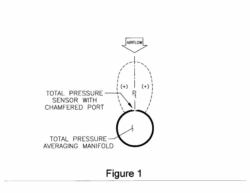
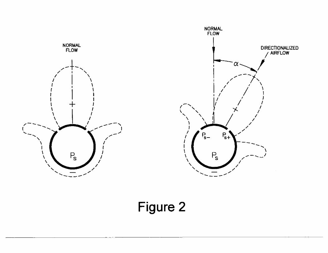
requiring very little straight duct run to maintain an accurate flow signal. The VOLU-probeoperates on a Fechheimer pitot derivative of the multi-point, self-averaging pitot principle tomeasure the total and static pressure components of airflow. Total pressure sensing ports, withchamfered entrances to greatly lessen entrance effects, are located on the leading surface of theVOLU-probe to sense the impact pressure (Pt) of the approaching air stream (Figure 1).Fechheimer static pressure sensing ports, positioned at designated angles offset from the flownormal vector, minimize the error-inducing effect of directional, non-normal airflow. As theflow direction veers from normal (Figure 2), one static sensor is exposed to a higher pressure (Ps+ part of Pt) while the other is exposed to a lower pressure (Ps - part of Pt). For angular flowwhere α = ±30 degrees offset from normal, these pressures are offsetting and the pressure sensedis the true static pressure. It is this unique design of the offset static pressure and the chamferedtotal pressure sensors (Figures 1 & 2) that make the VOLU-probe (and IBAM) relativelyinsensitive to approaching multi-directional, rotating airflow with yaw and pitch of up to 30degrees from normal, thereby assuring the accurate measurement of the sensed airflow ratewithout the presence of upstream airflow staighteners.
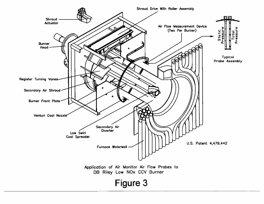
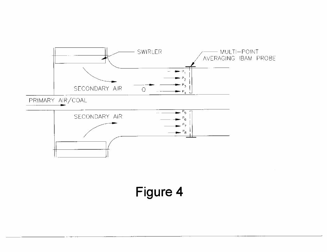
DevelopmentAmerican Electric Power’s Muskingum River 5, a 600 MW supercritical, pulverized coal firedunit with cell burners, was retrofit in 1993 with DB Riley’s CCV low NOx burners (referenceFigure 3). At the time, a DB Riley standard for the CCV included the use of a Brandt singlepoint shrouded air flow probe located just inside the register. In such a turbulent and non-uniform flow environment, this application produced very poor results and offered no value inthe balancing of secondary air flows between the 50 burners on this unit. With AEP havingalready successfully applied Air Monitor Corporation’s VOLU-probe technology to a roof-firedunit for dynamic per burner stoichiometric air flow control, AEP, DB Riley and AMC workedtogether to apply the technology to a sampling of 3 of the CCV burners at Muskingum River 5(reference Figure 4).
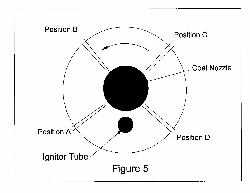
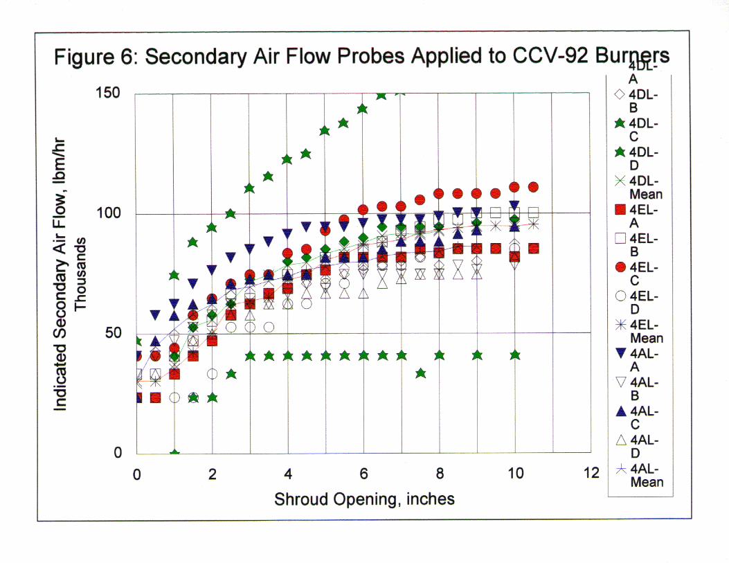
Because this application had oil lighter guide tubes in the secondary air annulus, the VOLU-probes were installed in four quadrants of the burner barrel as shown in Figure 5. Each probewas independently used to characterize the secondary air flow for each of the three outfittedburners. The purpose of this test array was to evaluate the effects of flow variations within acommon wind box and the impact of measuring flow in the shadow or downstream of the ignitorguide tube. All 3 burners selected are of the same flow rotation and located at the far left, rightand center of the wind box and at the same elevation in an attempt to assure the same wind boxto furnace differential. Each probe was also rotated 15 degrees into the direction of flow rotationto improve its sensitivity and the flow indication then corrected by a factor of cosine of 15degrees. The results of this testing are illustrated in Figure 6 and were very favorable. While theflow disruption created by the ignitor guide tube did result in a deviation from the mean for oneof the 3 burners tested (burner 4D Lower, probe positions C and D) the others and, in particular,those upstream of this upset showed very consistent values. In addition this testing was repeatedafter a period of six months of operation with repeated results and no routine attention to theprobes between the tests. While AEP has yet to outfit the balance of the Muskingum River 5burners with VOLU-probes, the balance of AEP’s low NOx burner retrofits (>500 burners)
utilizing the DB Riley CCV burner design are standardizing on the use of two VOLU-probes perburner. The selection of two probes is to provide both averaging for accuracy and redundancyfor troubleshooting (i.e. individual probe pluggage) as they are headered external to the windbox.
AEP has also developed their own patented low NOx burner technology applicable to its rooffired boilers in which the AMC VOLU-probe technology is being used to measure and controlindividual burner stoichiometries on a real-time basis based upon indicated pulverizer coalthroughputs. Since these units only have two burners associated with each pulverizer, fueldistribution issues are reasonably manageable and balance between coal conduits is assumed inthe controls. The result has been better air flow distribution on the units, better excess airbalance without operator interface, and, after application to five units with up to three years ofoperation, there has been no degradation in the system’s NOx emissions control capability.
The success of both applications mentioned above also prompted AEP to apply VOLU-probes tothe outer secondary air zone of previously retrofitted, FWEC designed, dual register, IFS lowNOx burners. The secondary air flow measurement supplied by FWEC with the burner wasfound to be greatly inadequate for the purpose of balancing air flows on the unit (800 MWsupercritical with 18 IFS burners on both the front and rear walls). While by design the outersecondary air zone flows with these burners are only intended to represent about 60% of the totalcombustion air to each burner the VOLU-probes were found to significantly help in improvingoverall unit air flow balance as indicated by economizer gas sampling grid analysis and the unit’sexcess air probe indications. The limitation of measuring only the major of a total of 3 secondaryair flow streams on this burner design coupled with difficulties in long term repeatable registeradjustments does not allow this application to present much hope of dynamic burner air flowbalancing and control. This application did assist though with achieving an additional 10%increment (0.05 lbm/MBtu) of full load NOx emission reductions on the unit to which it wasapplied.
Although AEP had developed confidence in the VOLU-probe technology, there remained somedetractors to its absolute accuracy, particularly when applied to a circular burner’s secondary airannulus. So in October of 1997 testing was performed using one of the DB Riley CCV low NOxburner registers fabricated for AEP’s Big Sandy Unit 1 in AMC Power’s wind tunnel. Theprimary purpose of the testing was to evaluate the absolute accuracy of the AM Power individualburner air monitor (IBAM) equipment in this turbulent, non-uniform flow field application withthe benefit of ASME flow nozzles for comparison. The results of this testing were evaluatedindependently by AMC Power (AMC), DB Riley (DBR) and AEPSC. A copy of the AMC andDBR reports can be requested directly from these sources. A summary of AEP's own analysisis summarized below.
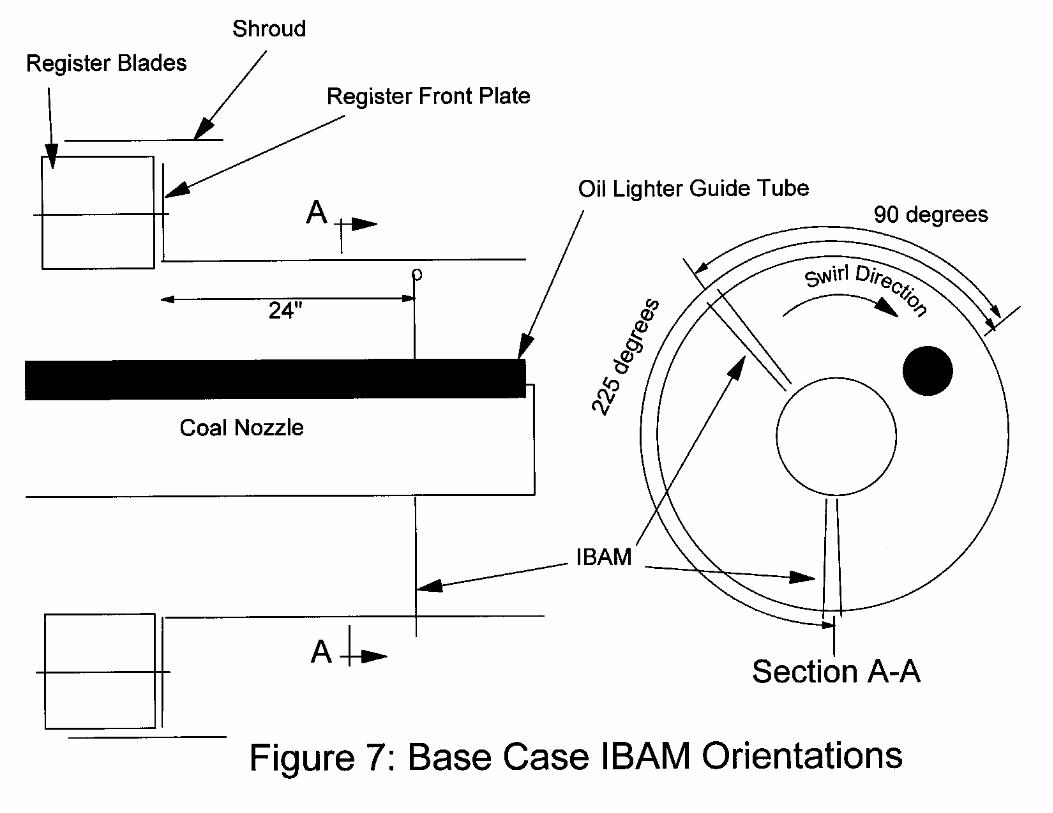
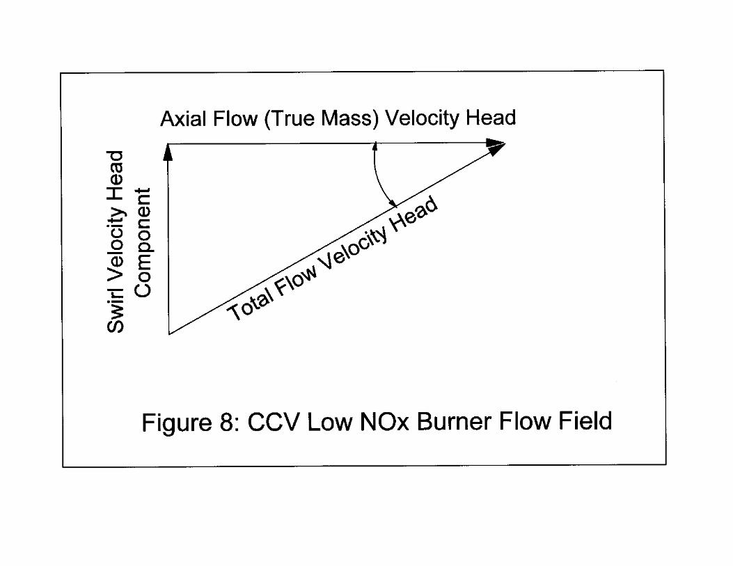
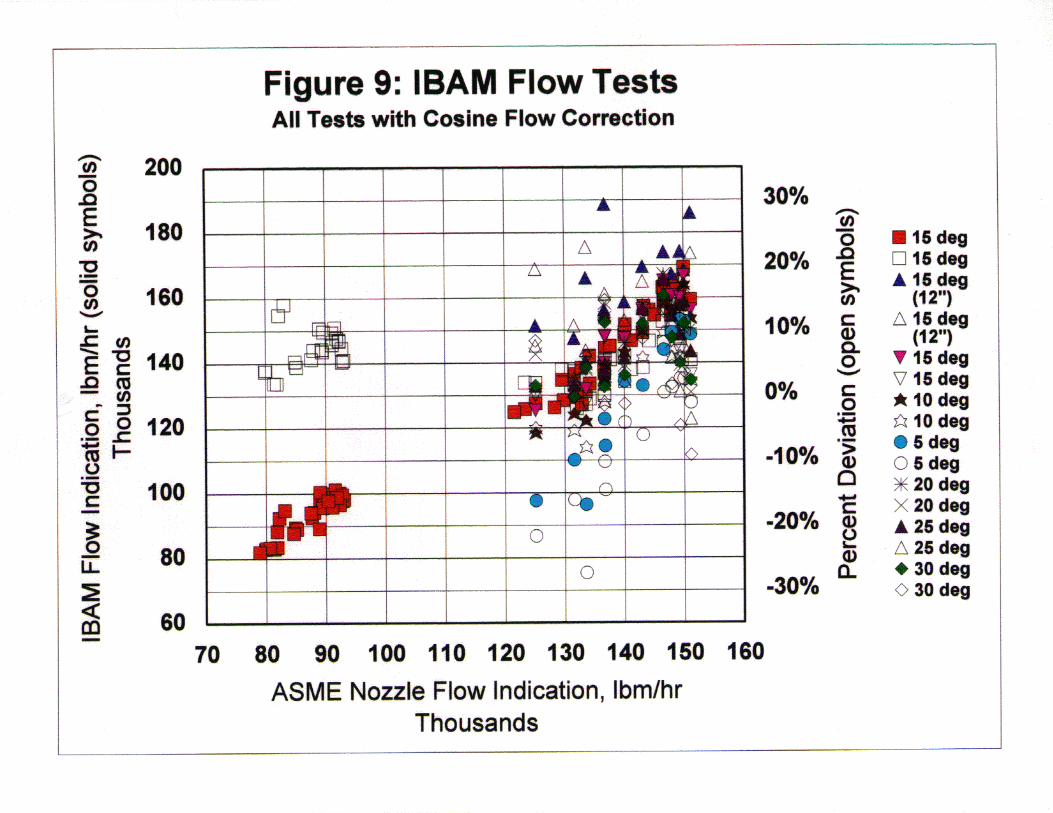
Testing and ResultsRepresentatives of AMC, DBR and AEPSC participated in the wind tunnel testing with theIBAM in the Big Sandy 1 CCV burner register. Matrices of tests were developed to test theaccuracy of the IBAM under a range of register conditions and flows. In the range of normalaverage Big Sandy 1 full-load per-burner flows (in cfm) and 50% of this flow, the registersettings were adjusted in 5-degree increments from 20 to 35 degrees open and with shroudpositions of 30, 50, 70 and 100% open. In addition, several sensitivities involving IBAM probepositions and orientations to flow direction were investigated. The base case orientation of theIBAM probes (reference Figure 7) was 24” downstream of the CCV register front plate,individually turned 15 degrees into the direction of flow rotation (Figure 7) and 90 and 225degrees upstream (rotationally) from the oil lighter guide tube. This is consistent with theorientations previously planned for all of the future AEP CCV burner retrofits. The other probeposition variations included moving the probes 12” closer to the register front plate and changingthe effective individual burner probe rotation from 15 degrees from axial to 5, 10, 20, 25, 30 and35 degrees from axial. Again the purpose of rotating the individual probes is to attempt to sensethe maximum (total) velocity head (Figure 8). To correct this back to an axial flow, we haveused a correction factor of the cosine of the probe rotational angle. A series of tests was also
CCV Low NOx BurnersFor the benefit of those unfamiliar with the CCV low NOx burner, it is the onlycommercial low NOx burner that, without the use of overfire air, was standardizedwith a single register configuration in the control of NOx emissions. This is effectivebecause of both the nozzle technology and the secondary air divertor at the end of thecoal nozzle. The secondary air divertor acts as a bluff body to help achieve goodflame attachment and provides enough secondary air separation to achieve the internalcombustion air staging commonly associated with a more complex dual-register lowNOx burner. From a practical and operational standpoint, the reduced complexityreduces initial capital investment and maintenance costs and eases optimizationefforts. With the optimization of a low NOx system, it is crucial that the dynamiccombustion conditions at all in-service burners be as balanced as feasible in order tobe able to measure the sensitivity of emissions to the available control parameters. Astarting point is to achieve the best possible balance across a unit between coal,primary air and secondary air flows for each burner.
While it is anticipated that the primary air and coal balance is currently less thandesirable, we are able to perform periodic calibration checks to assure than the millsare operated consistently, and the burner conduits have been orificed to theoreticallybalance the coal conduit pressure drops. However, all of the theory work has assumeda homogeneous air/fuel mixture exiting the mill classifiers. There are R&D effortsongoing within EPRI, Lehigh University and other organizations to develop the abilityto dynamically measure the actual “real time” coal conduit flow distributions.
performed without the oil lighter guide tube to assure that the accuracy with its inclusion was notaffected with the selected probe orientations.
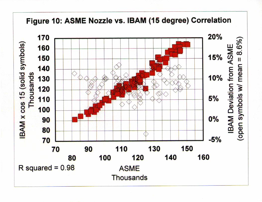
With the test cases of moving the probe axially to 12” from the register front plate and rotatingthe probes to 5 degrees from axial, the errors in the probe flow measurements became significant,with an total error band of 26-30% (reference Figures 9). For the balance of the test conditions,the error bands were generally less than 15% (Figure 10). These results suggest that the cosinecorrection is reasonable, but as also observed during the testing, the radial gradients in theamount of flow swirl was significant, and although not measured during these tests, the radialtotal flow gradients may also be significantly skewed and contributing to the levels of errormeasured.
After this testing was complete, portions of the data were randomly applied to a neural networkto then develop a model for predicting the true flow more accurately. Incorporated as inputs tothe neural network model were shroud position, register position and the raw IBAM flowindication. The result was the ability to reduce the margin of error to within 1%. The potential,therefore, exists to use either the cosine correction plus a fixed error bias value or the neuralnetwork modeled correlation to implement real time and reasonably accurate per burner flowmeasurement and respond with improved real time per burner flow control and balance.
Additional Wind Tunnel and Field TestingSubsequent wind tunnel testing has been performed with IBAMs in another CCV burner registerthat is of a different size and had a shroud that closed in the opposite direction of that previouslytested. The results were found to be consistent with the previous testing and demonstrated aslong as the probes orientations are consistent between the burners (i.e. distance from registerfront plate and degree of rotation relative to register swirl direction) the IBAM indicated versusactual ASME flow measurement correlations were essentially unchanged.
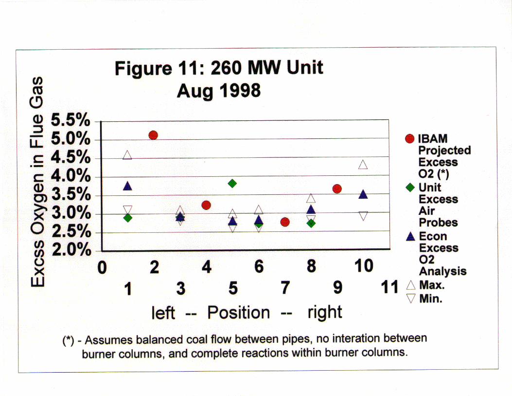
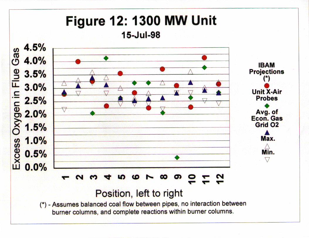
In the field, AEP has two recently completed CCV low NOx burner retrofit installationsincorporating two IBAMs per burner. One is on a 260 MWe sub critical opposed wall pulverizedcoal fired unit with 18 total burners unevenly split between the front and rear walls with 12 and 6respectively. The other is a 1300 MWe supercritical opposed wall coal fired unit with a total of96 burners evenly split between the front and rear walls in two high cell configurations. Fromboth units, a random sampling of available data has been taken to get a relative indication of theIBAM value. Each set of data included control room readings, 18 and 36 point, respectively,economizer outlet flue sampling grid gas analyses and individual burner IBAM readings. Thecontrol room data included unit excess air probe readings of which there is a normal complimentof 6 and 12 respectively per unit. Of the three, the finer economizer outlet flue gas samplinggrid analyses is naturally expected to be the most reliable representation of true excess oxygenlevels.
Based upon the IBAM flow readings, primary air flows and pulverizer throughputs, the averageexcess oxygen profile was predicted and then compared in Figures 11 and 12 to the indicatedexcess oxygen profiles from both the gas sampling grid analyses and the unit excess air probes.

Note that this comparison has been made with the assumption that all burner conduits from asingle pulverizer have balanced primary air and coal flows, burners flames within a column donot mix with flames from adjacent burner columns and all reactions within a burner column arecomplete. While it is recognized that some degree of mixing does occur between burner columnsand that there is some mal distribution between coal conduits, for both units, the IBAMsreasonably predict the profile created by the gas grid analyses and, in most cases, as well, if not,better than the unit excess air probes.