Embed Size (px)
DESCRIPTION
Thank You Sponsors. Baja Hybrid Drivetrain Design P14224. Thank You Sponsors. Problem Statement Identification of Critical Subsystems Identification of Vehicle States Analysis of Vehicle States Mechanical Subsystems Electrical Subsystems Mechanical Subsystem Interfaces Test Plan Update - PowerPoint PPT Presentation
Citation preview

Baja Hybrid Drivetrain DesignP14224
Thank YouSponsors

Thank YouSponsors
Problem StatementIdentification of Critical SubsystemsIdentification of Vehicle StatesAnalysis of Vehicle StatesMechanical SubsystemsElectrical SubsystemsMechanical Subsystem InterfacesTest Plan UpdateBudget Update
Agenda

The RIT Baja Team has expressed an interest in improving drivetrain efficiency and dynamic control. The drivetrain has not had a significant format change since the 90’s, using a single speed reduction box coupled with a CVT. While this has been and continues to be an effective means of transmitting power to the wheels, and is the preferred solution amongst the top performing teams, the team would like to explore other options; specifically a gas-electric design. The team would like to receive a working bench top prototype of the drive system for the purpose of testing the gas electric system to compare it to the existing system.
Problem Statement

Identification of Critical Subsystems
Engine and Alternator Mounting CR 3, 5 ER 5, 15, 19 DR 18, 19
Wheel and Traction Motor Mounting CR 5, 6 ER 12, 14, 17, 19 DR 20
Critical Subsystems - Mechanical

Controller Engine System Motor System Accumulator System Temperature User Input
Critical Subsystems - Electrical

CR 1, 2, 4, 5 ER 9, 10, 11, 12 DR 16, 17
Electrical – Engine System

CR 2, 4, 6, 13 ER 11, 12, 17 DR 1 - 7
Electrical – Motor System
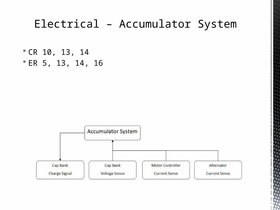
CR 10, 13, 14 ER 5, 13, 14, 16
Electrical – Accumulator System

CR 15 ER 6, 7 DR 14, 15
Electrical - Temperature

CR 1, 2, 4, 11, 13, 16 ER 5, 8, 9, 10, 13, 14, 21 DR 16, 17
Electrical – User Input

Identification and Analysis of Vehicle
States

Acceleration / Sled Pull / Mud Bog / Hill Climb Taxi Full Throttle/Accelerating Braking
Maneuverability / S+T / Rock Crawl Taxi Acceleration Braking Cornering
Endurance Taxi Acceleration Braking Cornering Constant Speed
Race Event Breakdown

Vehicle at Rest Engine Off Engine On
Cap bank full Cap bank not full
Vehicle in Motion *** Cap bank full/not full applies to all Accelerating/Full Throttle Coasting Braking Constant Speed Taxi
Vehicle States

Mechanical System loading at a minimum
Electrical No electrical power flow
At Rest, Engine Off

Mechanical System loading at a minimum
Electrical Alternator power in control closed Power available for motor
controller
At Rest, Engine On, Cap Full
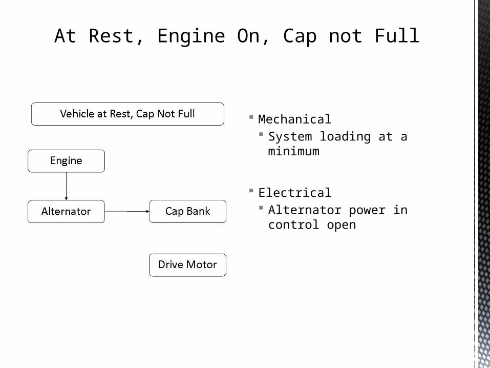
Mechanical System loading at a minimum
Electrical Alternator power in control open
At Rest, Engine On, Cap not Full

Mechanical Maximum drive torque developed Full tractive load
Electrical All power is flowed to the motor
controller As voltage of system drops
capacitor bank releases extra energy slowing the voltage fall
Accelerating/Full Throttle
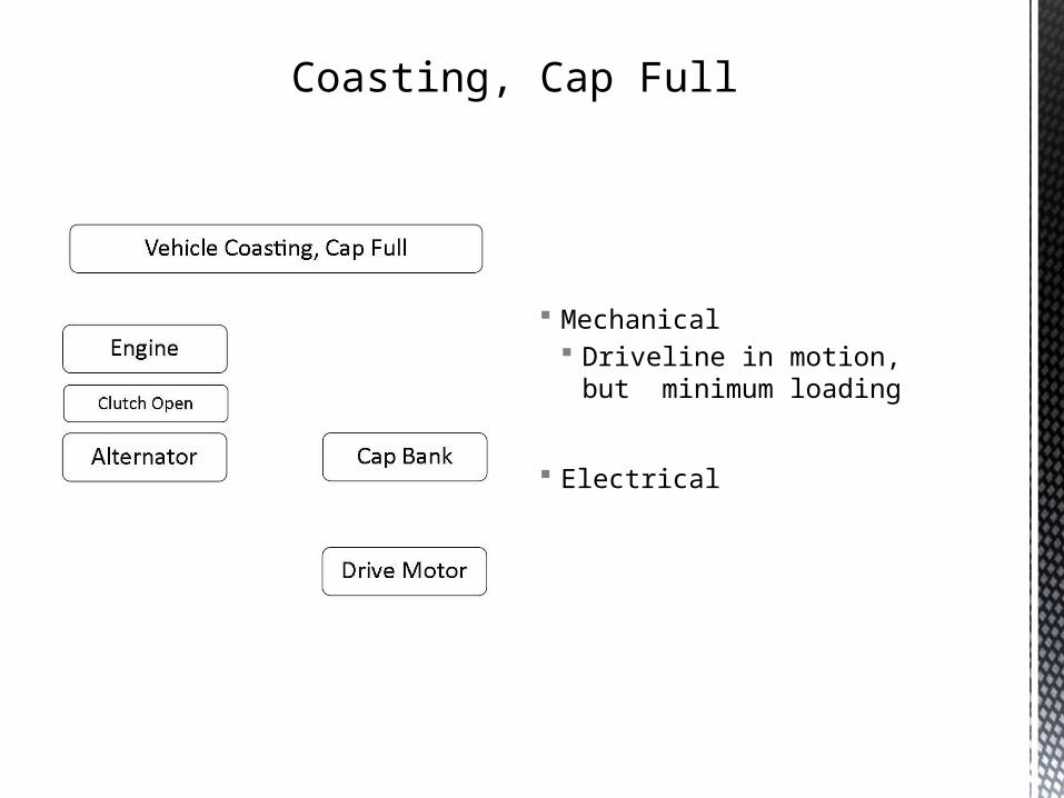
Mechanical Driveline in motion, but minimum
loading
Electrical
Coasting, Cap Full

Mechanical Driveline in motion, but minimum
loading
Electrical Regen power used to charge cap
bank
Coasting, Cap not Full

Mechanical Maximum drive torque developed Full tractive load
Electrical
Braking, Cap Full
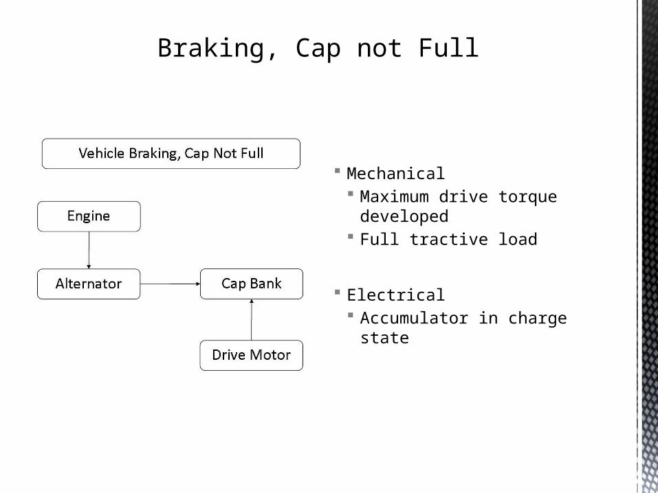
Mechanical Maximum drive torque developed Full tractive load
Electrical Accumulator in charge state
Braking, Cap not Full

Mechanical Intermediate drive torque
developed Intermediate tractive load
Electrical Alternator supplies all necessary
power to drive motor (engine may be revved down to conserve gas)
Constant Speed, Cap Full

Mechanical Intermediate drive torque
developed Intermediate tractive load
Electrical Extra power diverted to cap bank
charging
Constant Speed, Cap not Full

Mechanical Subsystems
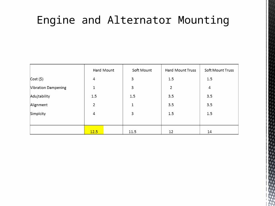
Engine and Alternator Mounting

Traction Motor and Drive Wheel Mounting

Electrical Subsystems

Engine Control System
Tow
erPr
o M
G995
R
Turn
igy
620D
MG
Spek
trum
A60
50
JR S
T47
Hite
c HS-
311
Cost 1 2 3 4 5Torque (oz-in) 3 3 3 3 3Speed (sec) 3 5 4 1 2Size (mm) 1.5 1.5 3.5 3.5 5Weight (grams) 1 2 5 3 4
TOTAL = 9.5 13.5 18.5 14.5 19
Servo Selection
Serv
o
Pneu
mati
c
Elce
ctric
Act
uato
r
Step
per M
otor
Cost 4 2 2 2Support System Complexity 4 1 2.5 2.5
Implementation 4 1 2.5 2.5Power Consumption 4 2.5 1 2.5
Accuracy (Increment Size) 4 1 2.5 2.5Lag 2 4 2 2
TOTAL = 22 11.5 12.5 14
Throttle Control Selection
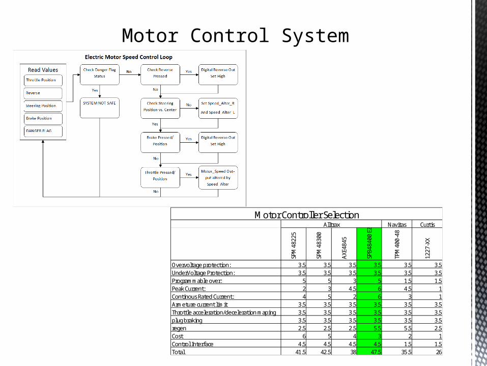
Motor Control System
Navitas Curtis
SPM
4822
5
SPM
4830
0
AXE4
845
SPB4
8400
EZ
TPM
400-
48
1227
-XX
Overvoltage protection: 3.5 3.5 3.5 3.5 3.5 3.5UnderVoltage Protection: 3.5 3.5 3.5 3.5 3.5 3.5Programmable over: 5 5 3 5 1.5 1.5Peak Current: 2 3 4.5 6 4.5 1Continous Rated Current: 4 5 2 6 3 1Armeture current limit 3.5 3.5 3.5 3.5 3.5 3.5Throttle acceleration/deceleration maping 3.5 3.5 3.5 3.5 3.5 3.5plug braking 3.5 3.5 3.5 3.5 3.5 3.5regen 2.5 2.5 2.5 5.5 5.5 2.5Cost 6 5 4 3 2 1Control Interface 4.5 4.5 4.5 4.5 1.5 1.5Total 41.5 42.5 38 47.5 35.5 26
Alltrax
Motor Controller Selection

Accumulator System (Small Scale Results)
Accumulator Steadily Charging Accumulator Steadily Discharging
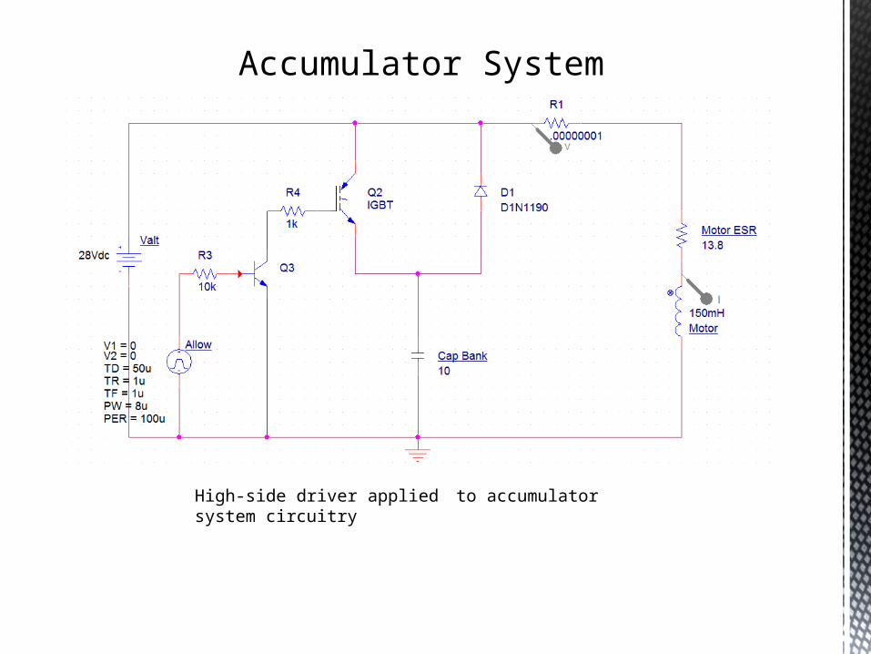
High-side driver applied to accumulator system circuitry
Accumulator System

Accumulator System
Accumulator software flow diagram

Temperature Control System
Max31855 AD594Resolution 2 1
Speed 1 2Start up time 1 2
Open thermocouple detection 1.5 1.5Low Power 1 2Built in CJC 1.5 1.5
Cost 1 2TOTAL: 9 12
Thermocouple Controller Selection

Mechanical Subsystem Interface
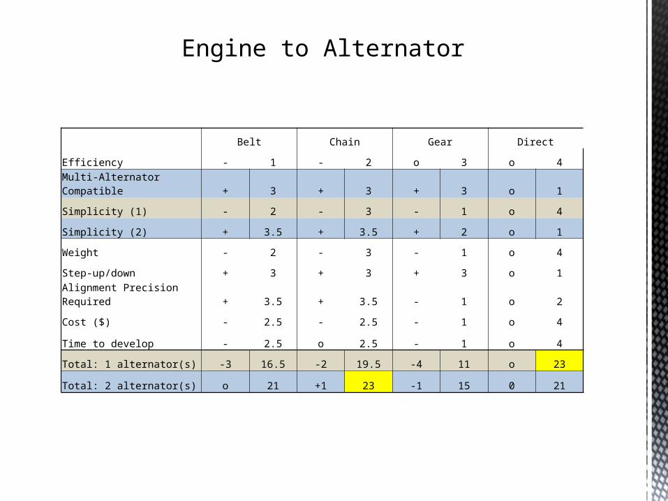
Belt Chain Gear Direct
Efficiency - 1 - 2 o 3 o 4
Multi-Alternator Compatible + 3 + 3 + 3 o 1
Simplicity (1) - 2 - 3 - 1 o 4
Simplicity (2) + 3.5 + 3.5 + 2 o 1
Weight - 2 - 3 - 1 o 4
Step-up/down + 3 + 3 + 3 o 1
Alignment Precision Required + 3.5 + 3.5 - 1 o 2
Cost ($) - 2.5 - 2.5 - 1 o 4
Time to develop - 2.5 o 2.5 - 1 o 4
Total: 1 alternator(s) -3 16.5 -2 19.5 -4 11 o 23
Total: 2 alternator(s) o 21 +1 23 -1 15 0 21
Engine to Alternator
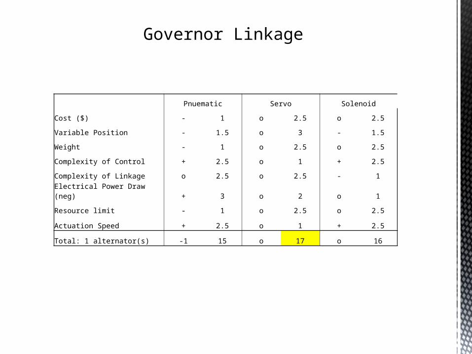
Governor Linkage
Pnuematic Servo Solenoid
Cost ($) - 1 o 2.5 o 2.5
Variable Position - 1.5 o 3 - 1.5
Weight - 1 o 2.5 o 2.5
Complexity of Control + 2.5 o 1 + 2.5
Complexity of Linkage o 2.5 o 2.5 - 1
Electrical Power Draw (neg) + 3 o 2 o 1
Resource limit - 1 o 2.5 o 2.5
Actuation Speed + 2.5 o 1 + 2.5
Total: 1 alternator(s) -1 15 o 17 o 16
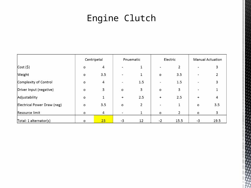
Engine Clutch

Test Plan Update

Test Plan Update
Mechanical Test Plan Traction motor selection
Receive torque information for RR selection
Begin cart design Begin Sub frame design Concept motor cooling Reduction ratio range selection
Electrical Test Plan Select microprocessor Begin controller board layout Concept motor cooling control Continue software development Continue development of
accumulator control circuitry Test:
Accumulator control circuitry Encoder inputs Servo control and power
Update bill of materials

Budget Update
P14224 Preliminary Budget Estimation
Item Cost Quantity Extended Cost Cost Quantity Extended Cost Cost Quantity Extended CostMotor 600.00 1 600.00 400.00 1 400.00 1 0.00Motor controller 500.00 1 500.00 300.00 1 300.00 433.32 1 0.00 Possible sponsorshipServo 20.00 1 20.00 8.00 1 8.00 8.00 1 0.00 SponsoredJ-Type Thermocouples 12.00 4 48.00 6.00 4 24.00 12.00 4 0.00 SponsoredThermocouple Controller 13.99 4 55.96 3.88 4 15.52 3.88 4 0.00 SponsoredAlternator "PMA" 500.00 1 500.00 70.00 2 140.00 2 0.002/0 gauge wire 3.75 30 112.50 1.89 30 56.70 30 0.00Misc connectors 5.00 6 30.00 5.00 6 30.00 6 0.00System controller 250.00 1 250.00 85.00 1 85.00 1 0.00Current sensing hall effect sensors 12.70 4 50.80 12.70 4 50.80 4 0.00Electronics enclosure 20.00 1 20.00 20.00 1 20.00 1 0.00Contactors 50 pin Deitch 22.20 2 44.40 22.20 2 44.40 2 0.00300amp 2/0 connectors Amphenol 7.30 2 14.60 7.30 2 14.60 2 0.00Accumulator (cap bank) 600.00 2 1200.00 120.00 4 480.00 4 0.00Safety equipment 100.00 1 100.00 50.00 1 50.00 1 0.00Test Bench 200.00 1 200.00 50.00 1 50.00 1 0.00Reduction (gears) 800.00 1 800.00 100.00 1 100.00 1 0.00
Total ($) 4546.26 Total ($) 1869.02 Total ($) 0.00
Low Cost OptionPreferred Option Propective Option

AppendixProject: P14224 Baja Hybrid Drivetrain
Revision #: 3 9/10/2013Customer
Rqmt. #Importance Description Comments/Status
CR1 o user input to control outputs incremental throttle controlCR2 + control electric motor impliedCR3 + semi-mobile unit to test with test device should be easily moved by a small groupCR4 + optimize engine output power engine and wheel speed controlled independentlyCR5 + must be able to test on a dyno type of dyno TBDCR6 + simulate 1 drive wheel impliedCR7 o keep projected system weight low materials may not be in project budgetCR8 o minimize production time production simplifiedCR9 + minimize cost budgetCR10 o accumulator must be able to reach a zero-charge point per Baja SAE rulesCR11 + system can be safely operated without PPE applies to driver and mechanicsCR12 o system complies with applicable SAE requirements per SAE collegiate rulesCR13 - regenerative braking charging accumulatorCR14 - must allow projected vehicle to pass in a expeditious manner TBD scope of workCR15 o cooling system if necessary, keep power loss and weight low TBDCR16 o must have a debug interface off the shelf interfaceCG1 ----- system output must meet or exceed R13 customer end goalCG2 ----- meet or exceed current system effi ciency compared to existing CVT drivetrain
Figure Customer requirements

Appendix
Figure Engineering requirements
Project: P14224 Baja Hybrid Drivetrain
Revision #: 3 9/10/2013
rqmt. # Importance Source Function Engr. Requirement (metric)Unit of
MeasureMarginal
ValueIdeal Value
Comments/StatusTest (how are you going to verify
satisfaction)S1 o CG1 projected RWHP ft-lbf/s 5.5 7.0 dyno pullS2 o CG1 projected peak RWTQ ft X lbf 2 278 dyno pullS3 + CG2 system effi ciency % 70% >80% theoretical evaluation, dyno pullS4 - CR7 projected system weight lb 60 <50 weigh system in modelS5 - CR14 stored power KJ 18.9 37.5 dyno pullS6 o CR15 cooling system power watts 150 100 measure performanceS7 o CR15 cooling system weight lb 7 5 weigh system S8 + CR11 system safety ---- ---- ---- See FMEAS9 + CR1 number of increments number 10 >100 throttle fluidityS10 + CR1 response time usec 100 <75 throttle response fluidityS11 + CR2 motor controller quantity 1 1 ea motor impliedS12 o CR5 dynamometer compatibility feature ---- ---- dyno type TBDS13 o CR13 maximum charging rate of accumulator amps 600 300 measure outputS14 o CR13 maximum braking torque due to regenerative braking ft-lbf 75 50 measure torqueS15 - CR3 maximum people to move quantity 4 2 impliedS16 o CR10 maximum accumulator potential in discharged state volts 0.5 0 measure across terminalsS17 - CR6 testable wheels quantity 1 1 impliedS18 o CR4 deviation from peak engine power % of max 25 5 peak power is at known RPM examine RPM variationS19 o CR9 maximize off the shelf components % 50 90 compare custom sub systems to premade countS20 + CR12 SAE standards compatibility (J1318, J1673) requirement ---- ----S21 o CR16 PC based debugging program requirement ---- ----

Appendix
Figure Developed requirements
Project: P14224 Baja Hybrid Drivetrain
Revision #: 0 10/28/2013
rqmt. #Importanc
eSource Function Dev. Requirement (metric)
Unit of Measure
Marginal Value
Ideal Value
Comments/StatusTest (how are you going to
verify satisfaction)DR1 Motor Controller overvoltage protection V 30.0 28.0DR2 Motor Controller under voltage protection V 20.0 22.0DR3 Motor Controller reprogrammable Requirement ----- -----DR4 Motor Controller peak current A 250< 300DR5 Motor Controller continuous rated current A 175< -----DR6 Motor Controller armature current limit Requirement ----- -----DR7 Motor Controller plug braking Requirement ----- -----DR8 System Controller encoder inputs Integer 2< -----DR9 System Controller analog inputs Integer 7<DR10 System Controller digital inputs Integer 3<DR11 System Controller DAC Integer 1<DR12 System Controller digital outputs Integer 2<DR13 System Controller PWM Integer 1<DR14 Thermocouple operational temps Farenheit 0-300 -----DR15 Thermocouple Controller read J-type thermocouples Requirement ----- -----DR16 Servo Controller minimum torque in-oz 36.3701< -----DR17 Servo Controller minimum stroke in 1.75< -----DR18 Eng Alt Mounting max deflection in 0.05 0DR19 Eng Alt Mounting transmitted vibration acceleration g 1 0.05DR20 Wheel Motor Mounting max deflection in 0.25 0
Wheel Motor Mounting reduction ratio ratio ----- ----- To be Determined


![Modeling of Fuel Cell Hybrid Vehicle in Modelica ... · membrane humidifier model [8][9][10] in the future. 2.3 Hybrid drivetrain The hybrid drivetrain is constructed in a similar](https://img.pdfslide.us/doc/110x75/6032cb4a22a63931bf0a81f9/modeling-of-fuel-cell-hybrid-vehicle-in-modelica-membrane-humidifier-model-8910.jpg)