Embed Size (px)
Citation preview
BAE SYSTEMS PROPRIETARY – Internal Use OnlyUnpublished Work Copyright 2014 BAE Systems. All rights reserved.
BAE Systems C2C SWAT Project - WF32 Shield V2.0 OnlyTutorial 4, Final V2Sep 2015
BAE SYSTEMS PROPRIETARY – Internal Use OnlyUnpublished Work Copyright 2014 BAE Systems. All rights reserved.
• Tutorial 4, Final describes how to correctly setup the ESC, servo, Digital Compass and GPS to your unit, including how to establish a connection to the SWAT Controller. This section is not compulsory.
• To add / remove components, you may modify the “SWAT_pin.cfg” and “SWATctrl.cfg” files on your SD Card respectively, after following the Set Up on the following slide.
• The Digital Compass used in this tutorial is the LSM303DLHC 3D Compass and Accelerometer Carrier with Voltage Regulator, and the GPS is the GP-635T, both of which you will be required to purchase.
• If you have purchased the Venus Logger GPS, please follow Steps 10 – 13 of Tutorial 3, instead of the GP-635T section in this tutorial.
2
Scope
BAE SYSTEMS PROPRIETARY – Internal Use OnlyUnpublished Work Copyright 2014 BAE Systems. All rights reserved.
Tutorial 4 > Set Up
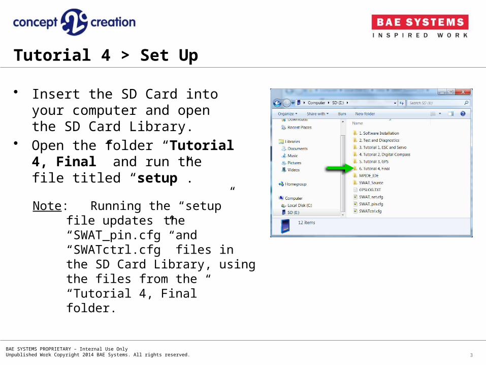
• Insert the SD Card into your computer and open the SD Card Library.
• Open the folder “Tutorial 4, Final” and run the file titled “setup”.
3
Note: Running the “setup” file updates the “SWAT_pin.cfg” and
“SWATctrl.cfg” files in the SD Card Library, using the files from the “Tutorial 4, Final” folder.
BAE SYSTEMS PROPRIETARY – Internal Use OnlyUnpublished Work Copyright 2014 BAE Systems. All rights reserved.
Tutorial 4 > Step 1
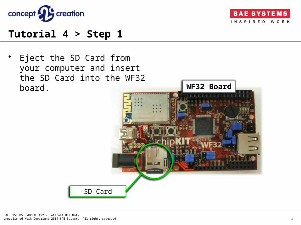
• Eject the SD Card from your computer and insert the SD Card into the WF32 board.
4
WF32 Board
SD Card
BAE SYSTEMS PROPRIETARY – Internal Use OnlyUnpublished Work Copyright 2014 BAE Systems. All rights reserved.
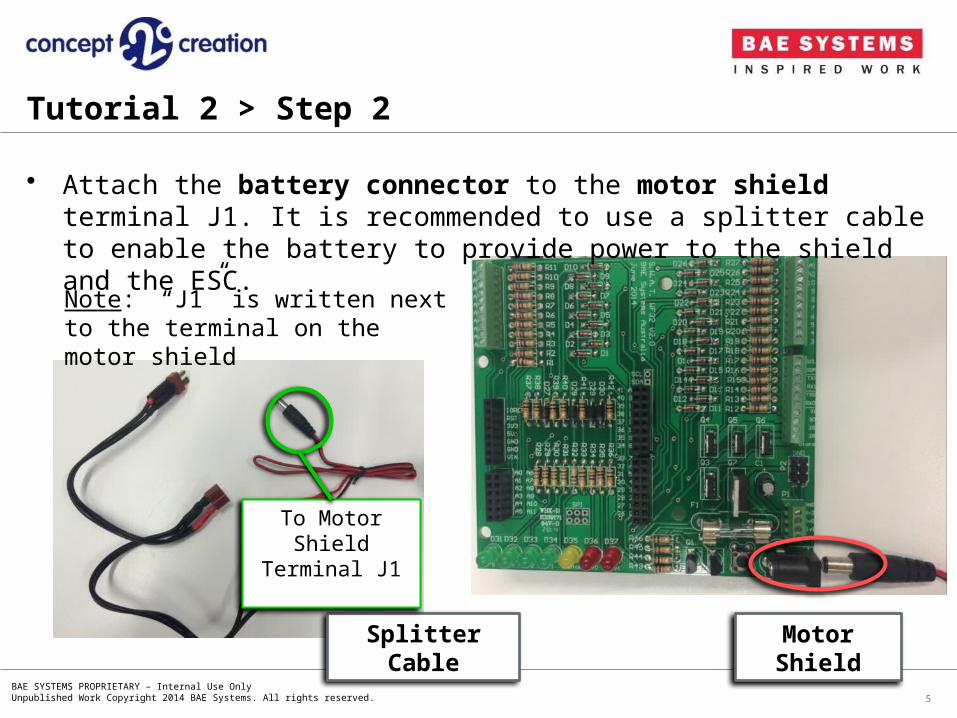
• Attach the battery connector to the motor shield terminal J1. It is recommended to use a splitter cable to enable the battery to provide power to the shield and the ESC.
5
Splitter Cable
To Motor Shield Terminal J1
Motor Shield
Note: “J1” is written next to the terminal on the motor shield
Tutorial 2 > Step 2
BAE SYSTEMS PROPRIETARY – Internal Use OnlyUnpublished Work Copyright 2014 BAE Systems. All rights reserved.
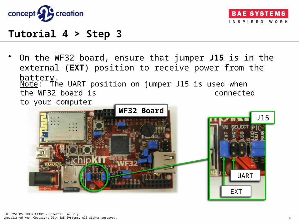
• On the WF32 board, ensure that jumper J15 is in the external (EXT) position to receive power from the battery.
6
Note: The UART position on jumper J15 is used when the WF32 board is connected to your computer
WF32 Board
EXT
UART
J15
Tutorial 4 > Step 3
BAE SYSTEMS PROPRIETARY – Internal Use OnlyUnpublished Work Copyright 2014 BAE Systems. All rights reserved.
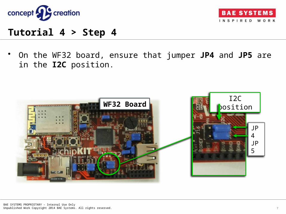
• On the WF32 board, ensure that jumper JP4 and JP5 are in the I2C position.
7
WF32 Board
JP4JP5
I2C position
Tutorial 4 > Step 4

BAE SYSTEMS PROPRIETARY – Internal Use OnlyUnpublished Work Copyright 2014 BAE Systems. All rights reserved.
• Physically attach the WF32 board underneath the motor shield using the connecting pins.
8
Tutorial 4 > Step 5
Note: Be careful not to bend any of the connecting pins.
Motor Shield
WF32
BAE SYSTEMS PROPRIETARY – Internal Use OnlyUnpublished Work Copyright 2014 BAE Systems. All rights reserved.
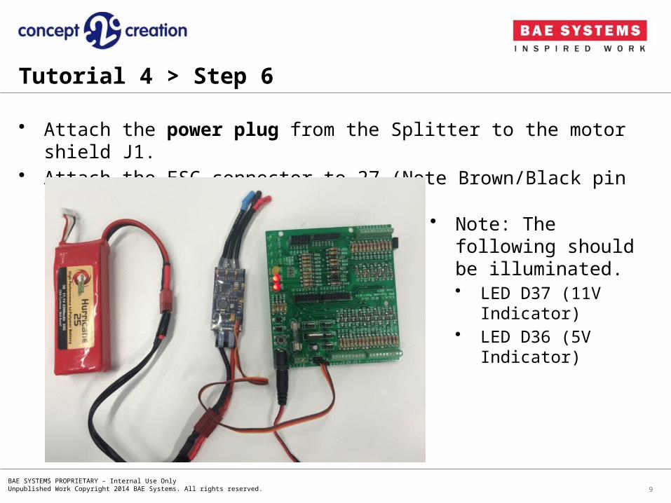
• Attach the power plug from the Splitter to the motor shield J1.• Attach the ESC connector to 27 (Note Brown/Black pin towards GND)
9
Tutorial 4 > Step 6
• Note: The following should be illuminated.• LED D37 (11V Indicator)• LED D36 (5V Indicator)
BAE SYSTEMS PROPRIETARY – Internal Use OnlyUnpublished Work Copyright 2014 BAE Systems. All rights reserved.
• DISCONNECT THE BATTERY BEFORE CONTINUING
10
Tutorial 4
BAE SYSTEMS PROPRIETARY – Internal Use OnlyUnpublished Work Copyright 2014 BAE Systems. All rights reserved.
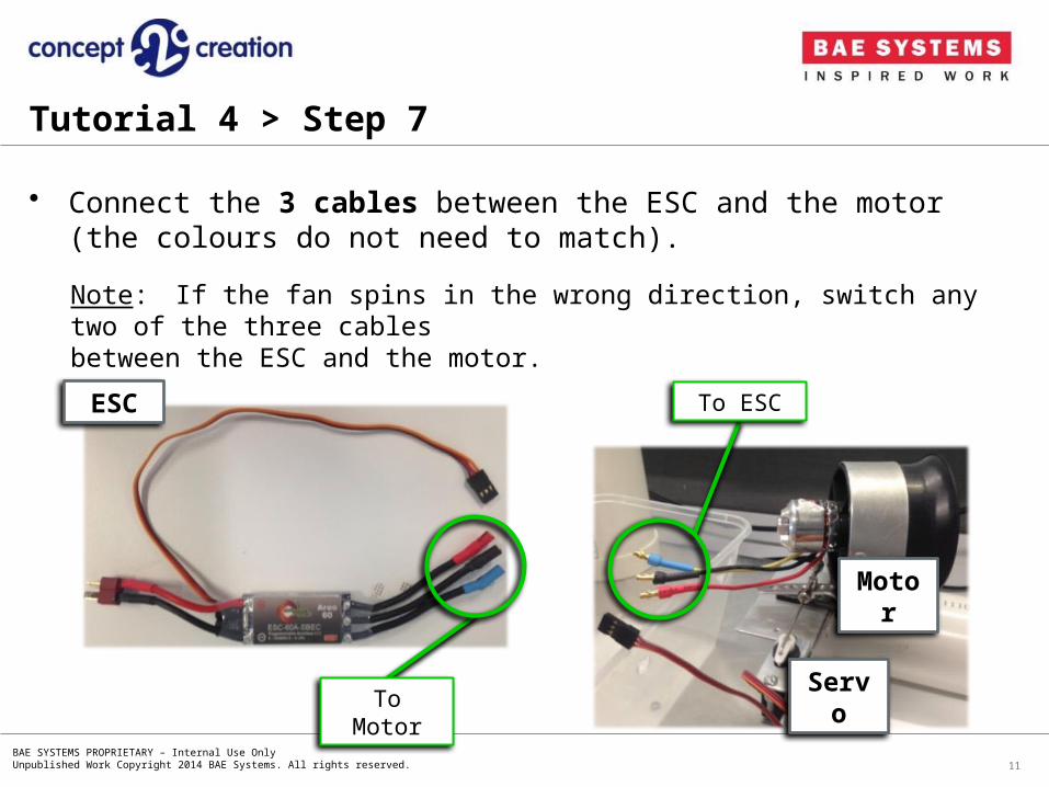
• Connect the 3 cables between the ESC and the motor (the colours do not need to match).
11
ESC
Motor
Servo
Note: If the fan spins in the wrong direction, switch any two of the three cables
between the ESC and the motor.
Tutorial 4 > Step 7
To Motor
To ESC
BAE SYSTEMS PROPRIETARY – Internal Use OnlyUnpublished Work Copyright 2014 BAE Systems. All rights reserved.
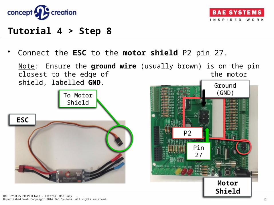
• Connect the ESC to the motor shield P2 pin 27.
12
ESC
Motor Shield
P2
Pin 27
Ground (GND)
Note: Ensure the ground wire (usually brown) is on the pin closest to the edge of the motor shield, labelled GND.
Tutorial 4 > Step 8
To Motor Shield
BAE SYSTEMS PROPRIETARY – Internal Use OnlyUnpublished Work Copyright 2014 BAE Systems. All rights reserved.
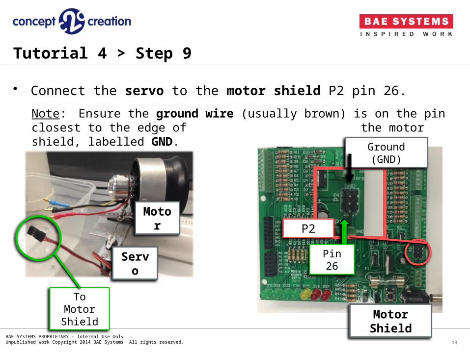
Motor
Servo
• Connect the servo to the motor shield P2 pin 26.
13
Note: Ensure the ground wire (usually brown) is on the pin closest to the edge of the motor shield, labelled GND.
To Motor Shield
Tutorial 4 > Step 9
P2
Pin 26
Ground (GND)
Motor Shield
BAE SYSTEMS PROPRIETARY – Internal Use OnlyUnpublished Work Copyright 2014 BAE Systems. All rights reserved.
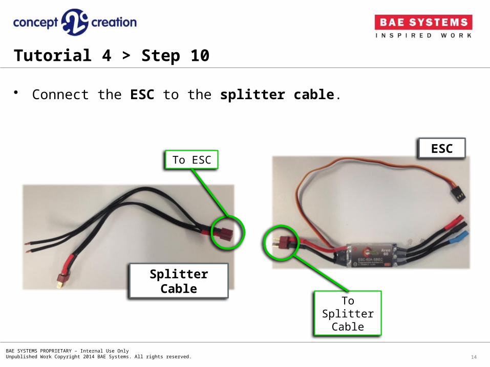
• Connect the ESC to the splitter cable.
14
ESC
To Splitter Cable
Splitter Cable
To ESC
Tutorial 4 > Step 10
BAE SYSTEMS PROPRIETARY – Internal Use OnlyUnpublished Work Copyright 2014 BAE Systems. All rights reserved.
• Up to four motors/pumps can be run from the 11.1V source (motor shield).
• If you would like to connect motors/pumps, please go to Step 11.
• If you would not like to connect any motors/pumps, please go to Step 12.
15
Tutorial 4 > Pumps

BAE SYSTEMS PROPRIETARY – Internal Use OnlyUnpublished Work Copyright 2014 BAE Systems. All rights reserved.
Positive wire
Negative wire
• Connect the positive wire (motor) to the 11.1V terminal on P1 (motor shield) and connect the negative wire (motor) to Digital I/O Pin 28, 29, 30 or 31 on P3 (motor shield).
• If you would like the motor to rotate in the opposite direction, switch the positive and negative wires.
• The mapping to Pins 28 – 31 is already included in the *.cfg files on the SD Card.
16
Tutorial 4 > Step 11
Motor
P3
P1
Motor ShieldPin 31Pin 30Pin 29Pin 28
GND+5V+11.1V

BAE SYSTEMS PROPRIETARY – Internal Use OnlyUnpublished Work Copyright 2014 BAE Systems. All rights reserved. 17
Tutorial 4 > Step 12
Digital Compass
Breadboard
Tip: Use different coloured wires between the digital compass and the motor
shield to distinguish connections easily.
Red for Vin, Black for GND, Blue for SCL, Orange for SDA.
• To connect the digital compass to the motor shield, use a breadboard and wires.
• When mounting the compass, have x-axis forward, y-axis right and z-axis down.
• The compass is heavily affected by the magnetic field of the motor. Mount it as far away as possible.
BAE SYSTEMS PROPRIETARY – Internal Use OnlyUnpublished Work Copyright 2014 BAE Systems. All rights reserved.
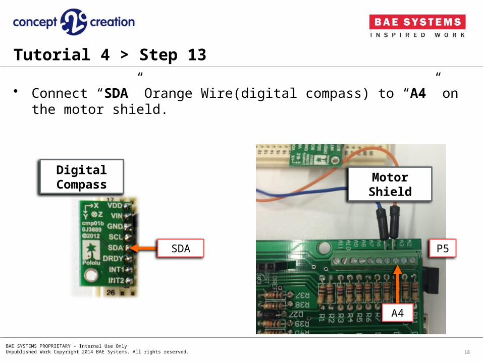
• Connect “SDA” Orange Wire(digital compass) to “A4” on the motor shield.
18
Tutorial 4 > Step 13
Digital Compass
Motor Shield
A4
P5SDA

BAE SYSTEMS PROPRIETARY – Internal Use OnlyUnpublished Work Copyright 2014 BAE Systems. All rights reserved.
• Connect “SCL” Blue Wire(digital compass) to “A5” on the motor shield.
19
Tutorial 4 > Step 14
Digital Compass
Motor Shield
A5
P5SCL

BAE SYSTEMS PROPRIETARY – Internal Use OnlyUnpublished Work Copyright 2014 BAE Systems. All rights reserved.
• Connect “GND” (digital compass) to either the second or third pins on the single pin row of P3, on the motor shield (illustrated in the diagram below).
20
Tutorial 4 > Step 15
Digital Compass
Note: This pin correlates to the GND pins in J3 of the WF32 board.
Motor Shield
GND
GND
BAE SYSTEMS PROPRIETARY – Internal Use OnlyUnpublished Work Copyright 2014 BAE Systems. All rights reserved.
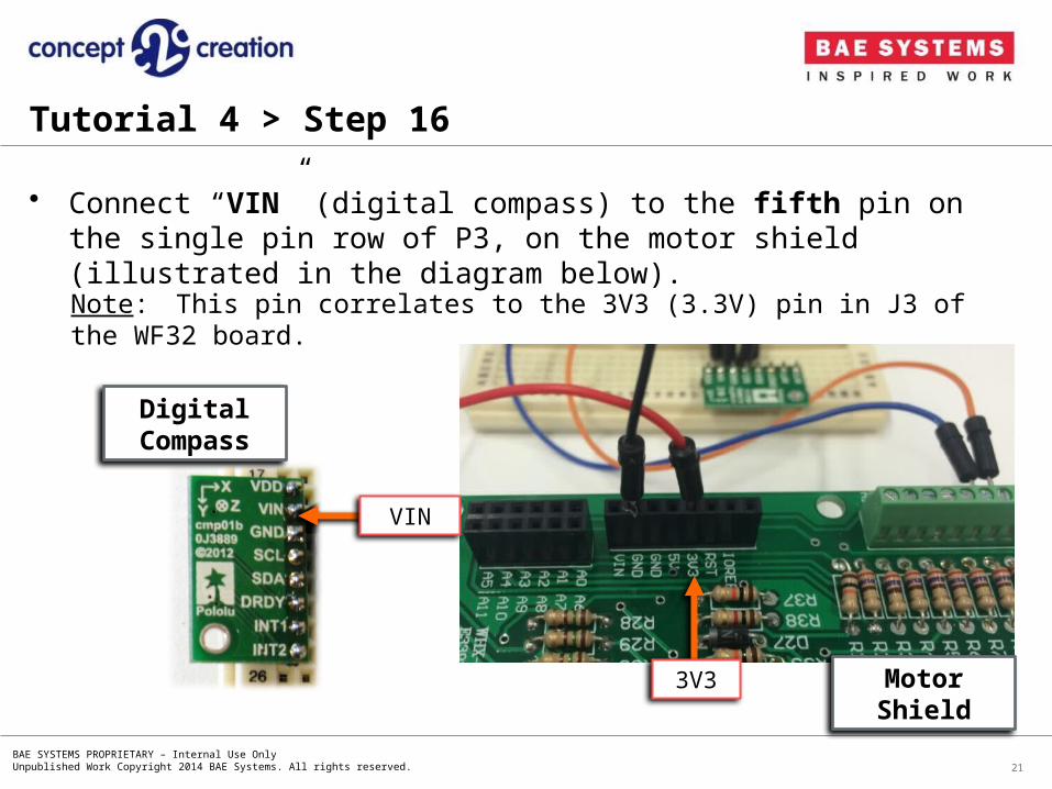
• Connect “VIN” (digital compass) to the fifth pin on the single pin row of P3, on the motor shield (illustrated in the diagram below).
21
Tutorial 4 > Step 16
Digital Compass
Note: This pin correlates to the 3V3 (3.3V) pin in J3 of the WF32 board.
Motor Shield
VIN
3V3
BAE SYSTEMS PROPRIETARY – Internal Use OnlyUnpublished Work Copyright 2014 BAE Systems. All rights reserved.
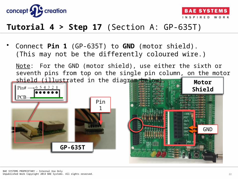
• Connect Pin 1 (GP-635T) to GND (motor shield).(This may not be the differently coloured wire.)
22
Tutorial 4 > Step 17 (Section A: GP-635T)
Note: For the GND (motor shield), use either the sixth or seventh pins from top on the single pin column, on the motor shield (illustrated in the diagram below).
Motor Shield
GND
GP-635T
Pin 1

BAE SYSTEMS PROPRIETARY – Internal Use OnlyUnpublished Work Copyright 2014 BAE Systems. All rights reserved.
• Connect Pin 3 (GP-635T) to Digital I/O Pin RX1, fourth from top, on connector P3 (motor shield).
23
Tutorial 4 > Step 18 (Section A: GP-635T)
GP-635T
Pin 3
Motor Shield
P3
Pin RX1
BAE SYSTEMS PROPRIETARY – Internal Use OnlyUnpublished Work Copyright 2014 BAE Systems. All rights reserved.
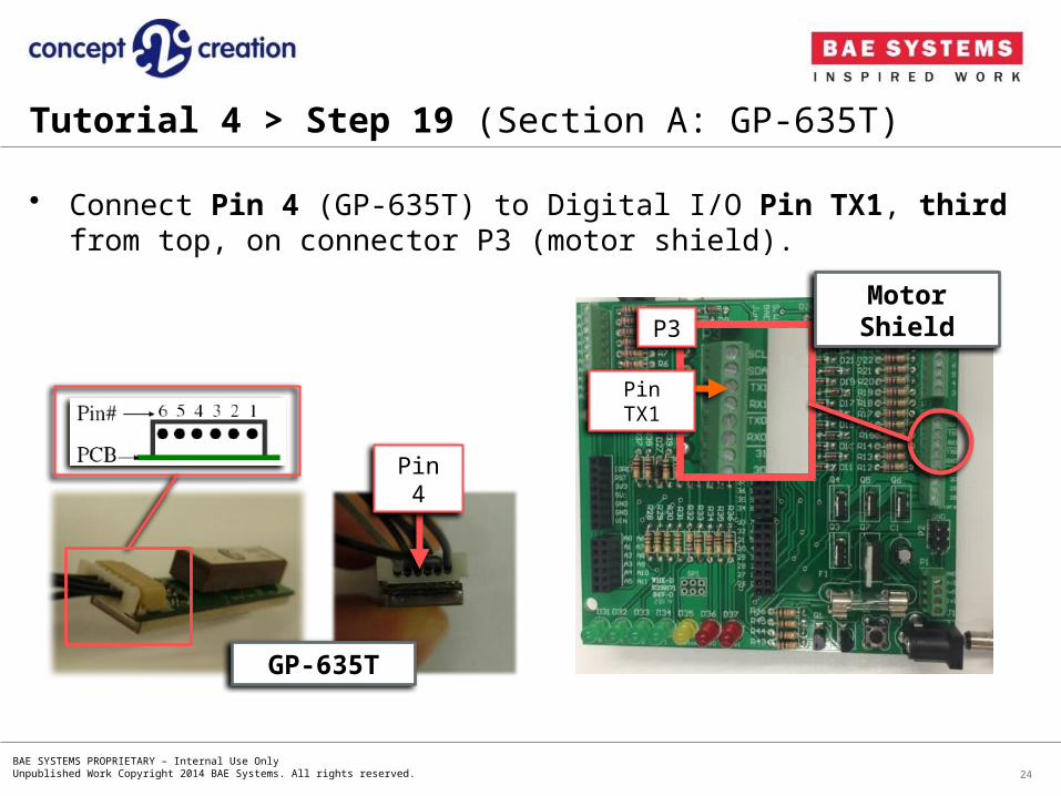
• Connect Pin 4 (GP-635T) to Digital I/O Pin TX1, third from top, on connector P3 (motor shield).
24
Tutorial 4 > Step 19 (Section A: GP-635T)
GP-635T
Pin 4
Motor ShieldP3
Pin TX1

BAE SYSTEMS PROPRIETARY – Internal Use OnlyUnpublished Work Copyright 2014 BAE Systems. All rights reserved.
• Connect Pins 2, 5 and 6 (GP-635T) to a 3.3V source (motor shield).
25
Tutorial 4 > Step 20 (Section A: GP-635T)
GP-635T
Pins 6, 5 and 2
Note: The 3.3V source on the motor shield is the fourth pin on the single pin column on the motor shield (illustrated in the diagram below).
Motor Shield
3V3
BAE SYSTEMS PROPRIETARY – Internal Use OnlyUnpublished Work Copyright 2014 BAE Systems. All rights reserved.
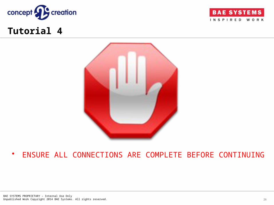
• ENSURE ALL CONNECTIONS ARE COMPLETE BEFORE CONTINUING
26
Tutorial 4

BAE SYSTEMS PROPRIETARY – Internal Use OnlyUnpublished Work Copyright 2014 BAE Systems. All rights reserved.
• Attach the motor shield, using the splitter cable, to the battery, to power up the board.
27
Splitter Cable
To Battery
To Splitter Cable
Battery
Note: The battery is always the last component to connect.
Tutorial 4 > Step 21

BAE SYSTEMS PROPRIETARY – Internal Use OnlyUnpublished Work Copyright 2014 BAE Systems. All rights reserved.
• Turn on your Wi-Fi unit and connect your computer to this.• Open the “SWAT Controller” on your computer (previously installed).
28
SWAT Controller
Tutorial 4 > Step 22
BAE SYSTEMS PROPRIETARY – Internal Use OnlyUnpublished Work Copyright 2014 BAE Systems. All rights reserved.
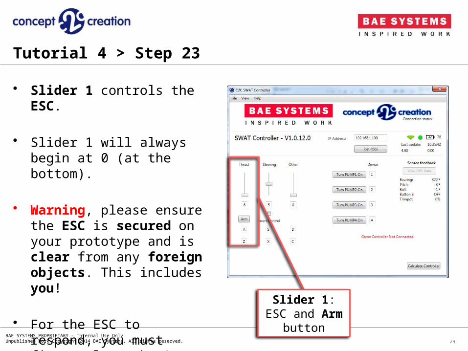
• Slider 1 controls the ESC.
• Slider 1 will always begin at 0 (at the bottom).
• Warning, please ensure the ESC is secured on your prototype and is clear from any foreign objects. This includes you!
• For the ESC to respond, you must first select the Arm button.
29
Tutorial 4 > Step 23
Slider 1: ESC and Arm button
BAE SYSTEMS PROPRIETARY – Internal Use OnlyUnpublished Work Copyright 2014 BAE Systems. All rights reserved.
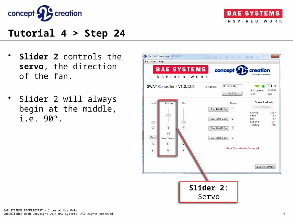
• Slider 2 controls the servo, the direction of the fan.
• Slider 2 will always begin at the middle, i.e. 90º.
30
Tutorial 4 > Step 24
Slider 2: Servo

BAE SYSTEMS PROPRIETARY – Internal Use OnlyUnpublished Work Copyright 2014 BAE Systems. All rights reserved.
• Note that Slider 3 is not set in the default code.
• You may modify these yourself in the “SWAT_pin.cfg” and “SWATctrl.cfg” files on the SD Card.
31
Tutorial 4 > Step 25
Slider 3

BAE SYSTEMS PROPRIETARY – Internal Use OnlyUnpublished Work Copyright 2014 BAE Systems. All rights reserved. 32
Tutorial 4 > Step 26
Pump Controls
• If you connected a motor/pump, you will be able to test it using the buttons, switching them ON and OFF.
• The LEDS on D31 – D34, will also correspond to what motor/pump is operating.
• If an LED is placed on D35, this will correspond to any motor/pump operating.
Motor ShieldD31D32D33D34
D35

BAE SYSTEMS PROPRIETARY – Internal Use OnlyUnpublished Work Copyright 2014 BAE Systems. All rights reserved.
• Once the “SWAT Controller” has established a connection to the WF32, feedback can be seen for the Digital Compass (Bearing, Pitch and Roll).
33
Tutorial 4 > Step 27
SWAT Controller
Digital Compass feedback

BAE SYSTEMS PROPRIETARY – Internal Use OnlyUnpublished Work Copyright 2014 BAE Systems. All rights reserved.
• Once the “SWAT Controller” has established a connection, select the View GPS Data button.
• A new window will open, with various tabs, in which your Position will be displayed in the GPRMC tab.
• You may also view the GPGSV tab, in which the current satellites can be seen.
34
Tutorial 4 > Step 28
View GPS Data
BAE SYSTEMS PROPRIETARY – Internal Use OnlyUnpublished Work Copyright 2014 BAE Systems. All rights reserved.
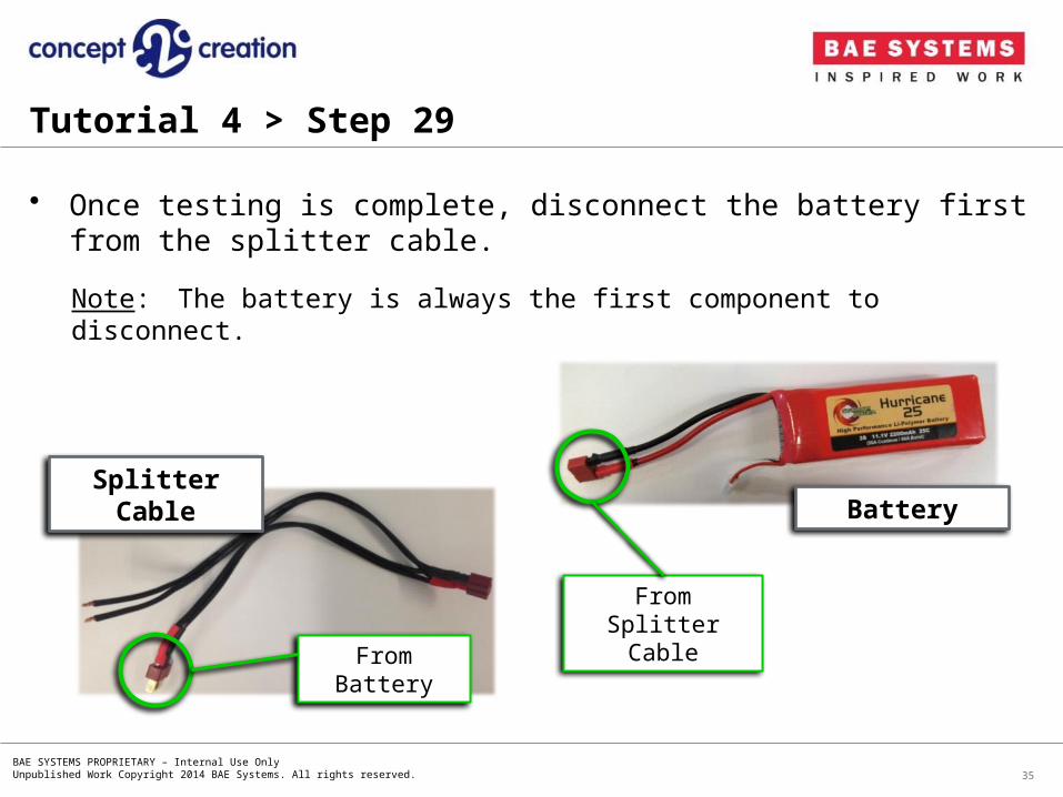
• Once testing is complete, disconnect the battery first from the splitter cable.
35
Note: The battery is always the first component to disconnect.
Splitter Cable
From Battery
From Splitter Cable
Battery
Tutorial 4 > Step 29