Embed Size (px)
Citation preview
2017-04 QSG Page 1 of 17 v1.5.0
BACnet & Modbus Interface Quick Start Guide Version 1.5.0
Table of Contents Quick Start with Software Tool ..................................................................................................................... 2
Software Tool Additional Configuration ....................................................................................................... 6
Procon MelcoBEMS MINI (A1M) Information .............................................................................................. 9
Introduction .............................................................................................................................................. 9
Requirements ............................................................................................................................................ 9
Default Settings ......................................................................................................................................... 9
Procon MelcoBEMS MINI (A1M) Configuration Manager Tool Information .............................................. 10
Introduction ............................................................................................................................................ 10
Requirements .......................................................................................................................................... 10
Appendix: .................................................................................................................................................... 11
DIP switch settings: ................................................................................................................................. 11
RS-485 MAC Addressing: ..................................................................................................................... 11
Communication Settings: .................................................................................................................... 11
Protocol selection: .............................................................................................................................. 11
Deadband mode:................................................................................................................................. 11
RS-485 Termination: ............................................................................................................................... 12
Status LEDs: ............................................................................................................................................. 12
Points List: ............................................................................................................................................... 13
BACnet Object List: ............................................................................................................................. 13
Modbus Table – Air-to-Air Systems: ................................................................................................... 14
2017-04 QSG Page 2 of 17 v1.5.0
Quick Start with Software Tool 1. Download software from MyLinkDrive.com under the PAC-UKPRC001-CN-1 support page
software section
a. http://meus1.mylinkdrive.com/item/PAC-UKPRC001-CN-1.html
2. Install the MelcoBEMS MINI (A1M) Configure Manager software tool
a. Ensure the power is turned off for the Mitsubishi Electric outdoor and indoor units of
the system that will be integrated.
3. Before configuring the BACnet & Modbus Interface device, the third party building/home
automation system contractor needs to supply the MAC address, device instance number, baud
rate and any other network settings needed for the RS-485 communication network.
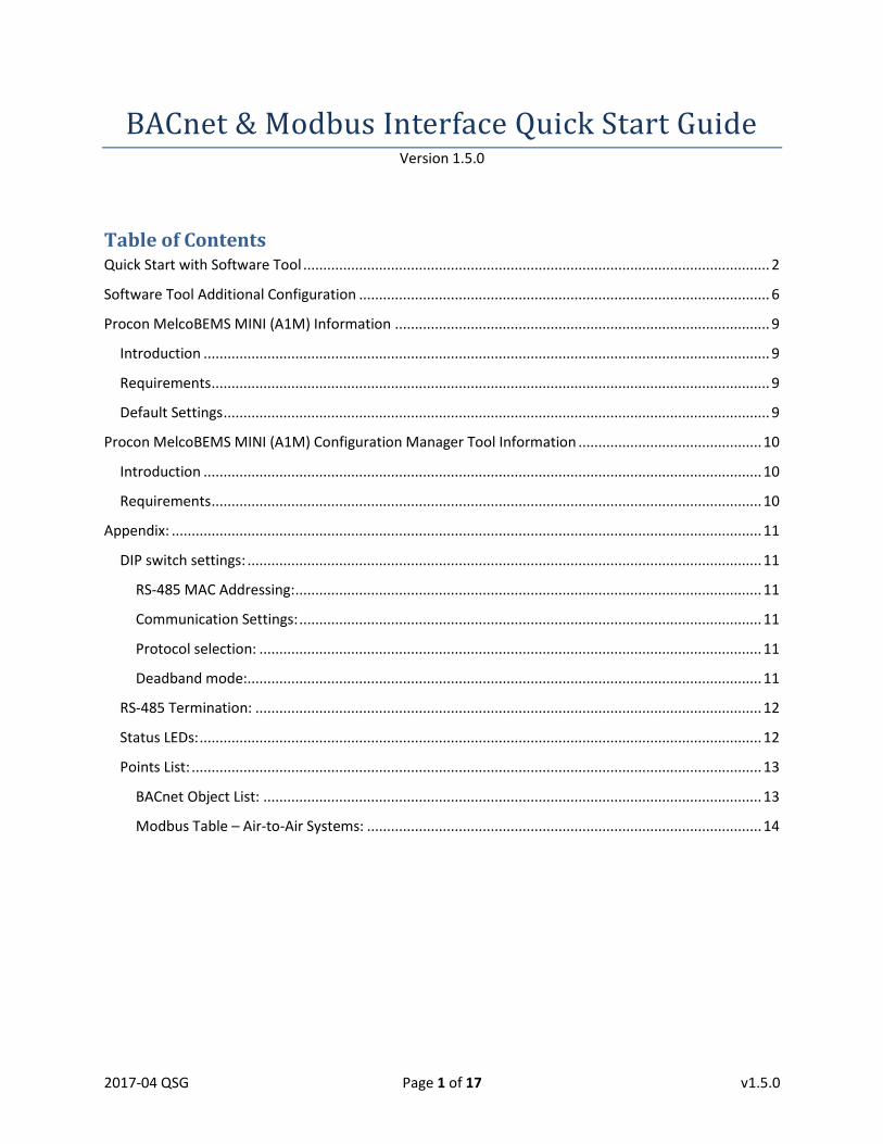
4. Make sure dip switches 1, 6, and 7 are ON and the remaining dips switches are OFF when
trying to connect to the configuration tool software. Figure 1 shows the correct dip switch
position for this step.
5. Connect the BACnet & Modbus Interface device to connector CN105 on the PCB of the powered
off Mitsubishi Electric unit that will be integrated.
a. If there are more than one interfaces, continue to plug in the remaining interface
devices into the CN105 on the PCB of a powered off Mitsubishi Electric unit.
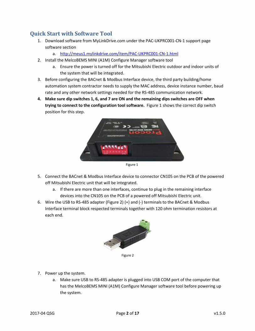
6. Wire the USB to RS-485 adapter (Figure 2) (+) and (-) terminals to the BACnet & Modbus
Interface terminal block respected terminals together with 120 ohm termination resistors at
each end.
7. Power up the system.
a. Make sure USB to RS-485 adapter is plugged into USB COM port of the computer that
has the MelcoBEMS MINI (A1M) Configure Manager software tool before powering up
the system.
Figure 1 Figure 1
Figure 2
2017-04 QSG Page 3 of 17 v1.5.0
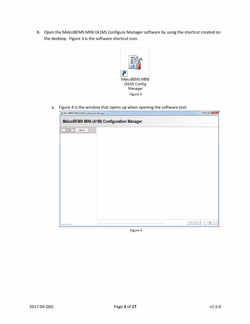
8. Open the MelcoBEMS MINI (A1M) Configure Manager software by using the shortcut created on
the desktop. Figure 3 is the software shortcut icon.
a. Figure 4 is the window that opens up when opening the software tool.
Figure 4
Figure 3
2017-04 QSG Page 4 of 17 v1.5.0
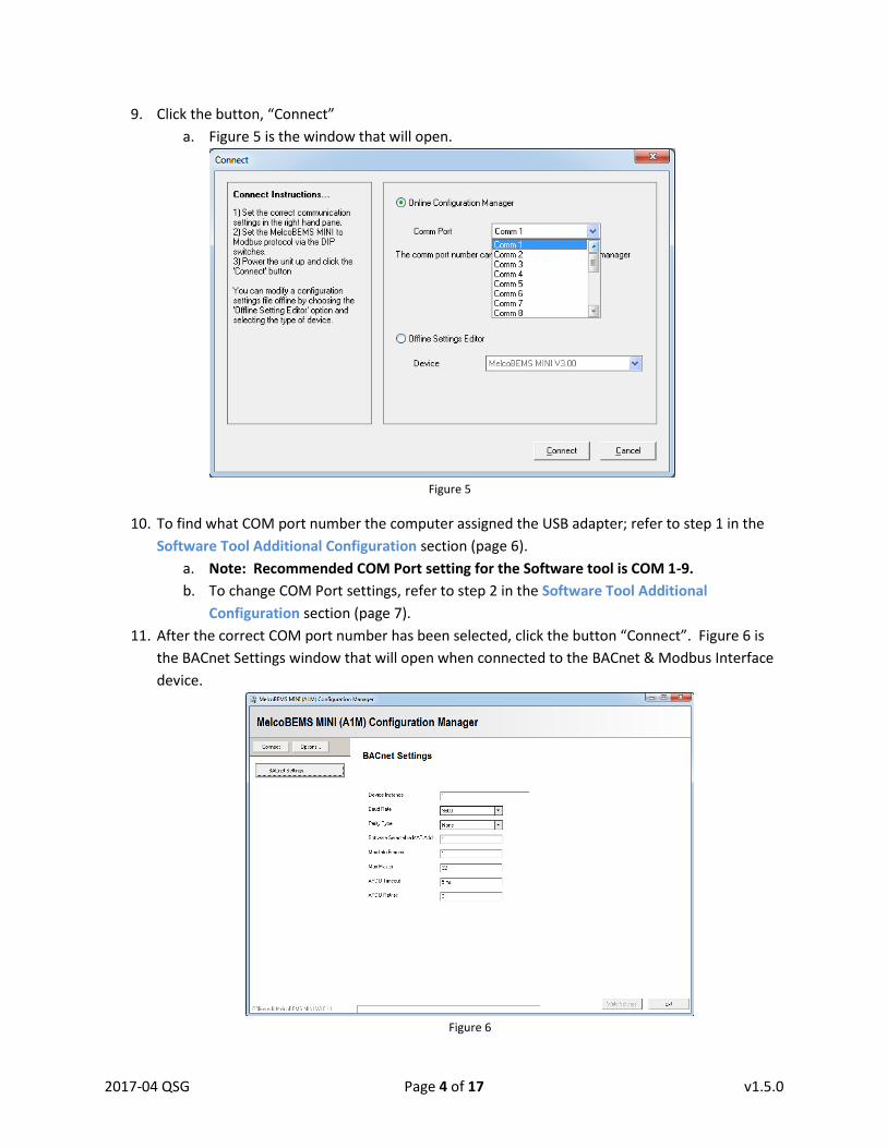
9. Click the button, “Connect”
a. Figure 5 is the window that will open.
Figure 5
10. To find what COM port number the computer assigned the USB adapter; refer to step 1 in the
Software Tool Additional Configuration section (page 6).
a. Note: Recommended COM Port setting for the Software tool is COM 1-9.
b. To change COM Port settings, refer to step 2 in the Software Tool Additional
Configuration section (page 7).
11. After the correct COM port number has been selected, click the button “Connect”. Figure 6 is
the BACnet Settings window that will open when connected to the BACnet & Modbus Interface
device.
Figure 6
2017-04 QSG Page 5 of 17 v1.5.0
a. If unable to connect to the BACnet & Modbus Interface device, look back at the previous
steps.
i. Verify dip switches are set correctly
ii. Verify wiring polarity is correct
iii. Verify computer USB COM port is correct
12. Enter the settings for each interface into the BACnet Settings window provided by the third
party building/home automation system contractor.
13. Click the button “Write Settings” in the lower right hand corner after all the settings have been
entered correctly. You will see the Right LED (RS-485 ACK) light blink when clicking the
“Write Settings” button.
14. After all interfaces have been configured, power down the system and set the dip switches
accordingly to site requirements.
a. When ALL dip switches 1 – 5 are set to the ON position, the BMS system sees the
device MAC address that is set in the software.
i. Refer to Appendix section (page 11) for additional information on dip switch
positions.
b. Wire all interfaces to the master controller following the BACnet or Modbus
communication wiring protocols.
i. 2 termination resistors (typically 120 ohms) are required at the start and end of
the communication bus.
15. Power up the system.
16. Check each interface to see if there is communication with the indoor unit and master controller
by looking at the two acknowledgement LEDs
a. Left LED (AC ACK) confirms power and communication to indoor unit by blinking.
b. Right LED (RS-485 ACK) confirms RS-485 communication by blinking.
i. If the right LED is solid and not blinking, the device is not communicating with
the BMS system. Once communication has been established, the RS-485 ACK
light will start blinking.
1. Verify the device settings are setup correctly.
2. Verify the device is added to the BMS system network.
3. Verify RS-485 wiring.
2017-04 QSG Page 6 of 17 v1.5.0
Software Tool Additional Configuration
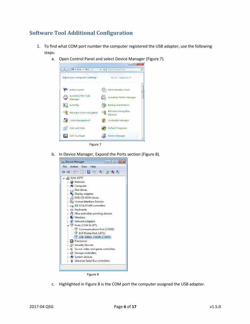
1. To find what COM port number the computer registered the USB adapter, use the following
steps:
a. Open Control Panel and select Device Manager (Figure 7).
Figure 7
b. In Device Manager, Expand the Ports section (Figure 8).
Figure 8
c. Highlighted in Figure 8 is the COM port the computer assigned the USB adapter.
2017-04 QSG Page 7 of 17 v1.5.0
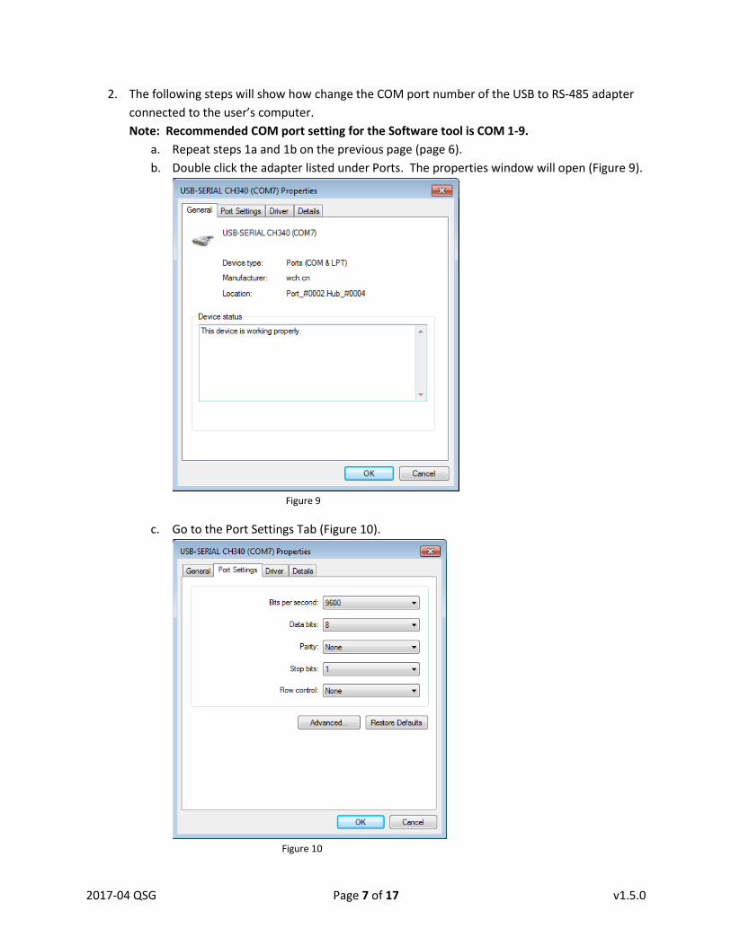
2. The following steps will show how change the COM port number of the USB to RS-485 adapter
connected to the user’s computer.
Note: Recommended COM port setting for the Software tool is COM 1-9.
a. Repeat steps 1a and 1b on the previous page (page 6).
b. Double click the adapter listed under Ports. The properties window will open (Figure 9).
Figure 9
c. Go to the Port Settings Tab (Figure 10).
Figure 10
2017-04 QSG Page 8 of 17 v1.5.0
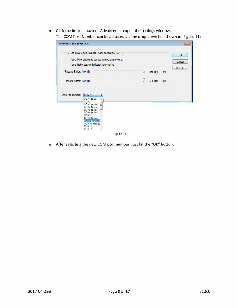
d. Click the button labeled “Advanced” to open the settings window.
The COM Port Number can be adjusted via the drop down box shown on Figure 11:
Figure 11
e. After selecting the new COM port number, just hit the “OK” button.
2017-04 QSG Page 9 of 17 v1.5.0
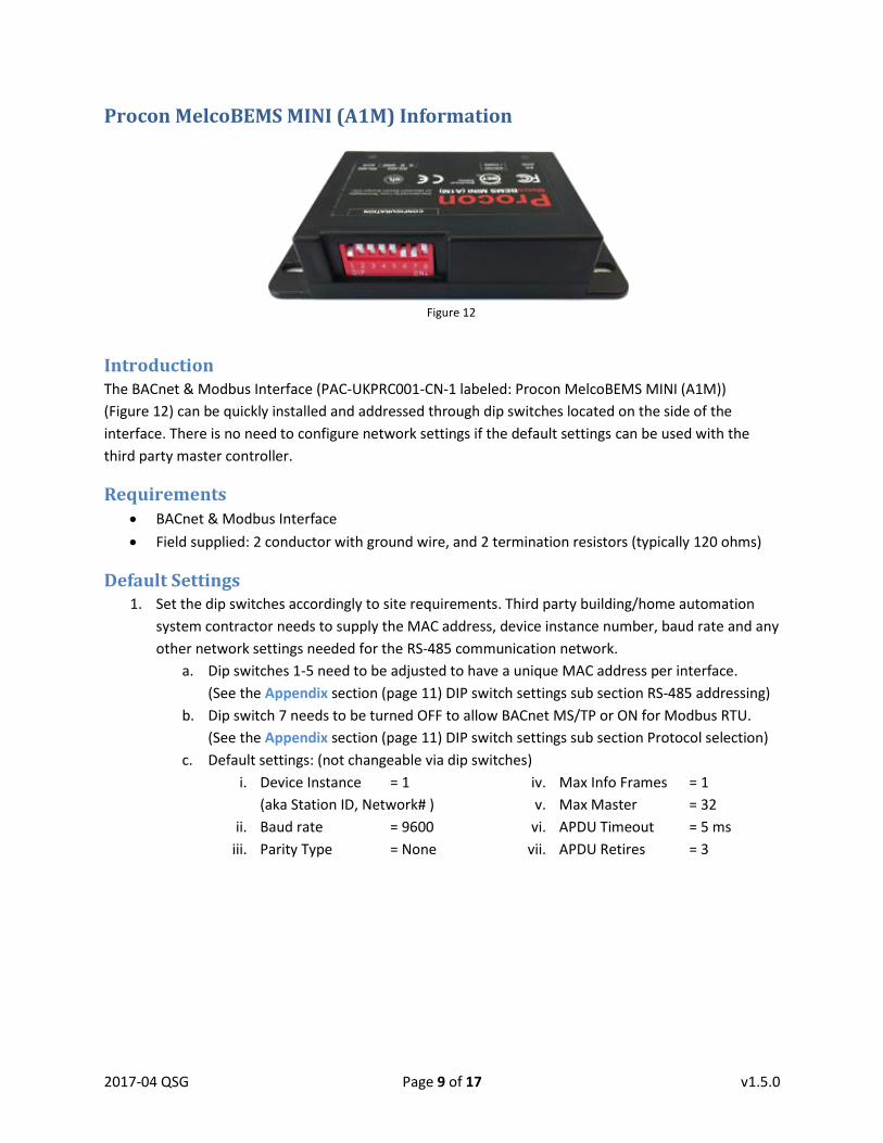
Procon MelcoBEMS MINI (A1M) Information
Introduction The BACnet & Modbus Interface (PAC-UKPRC001-CN-1 labeled: Procon MelcoBEMS MINI (A1M))
(Figure 12) can be quickly installed and addressed through dip switches located on the side of the
interface. There is no need to configure network settings if the default settings can be used with the
third party master controller.
Requirements BACnet & Modbus Interface
Field supplied: 2 conductor with ground wire, and 2 termination resistors (typically 120 ohms)
Default Settings 1. Set the dip switches accordingly to site requirements. Third party building/home automation
system contractor needs to supply the MAC address, device instance number, baud rate and any
other network settings needed for the RS-485 communication network.
a. Dip switches 1-5 need to be adjusted to have a unique MAC address per interface.
(See the Appendix section (page 11) DIP switch settings sub section RS-485 addressing)
b. Dip switch 7 needs to be turned OFF to allow BACnet MS/TP or ON for Modbus RTU.
(See the Appendix section (page 11) DIP switch settings sub section Protocol selection)
c. Default settings: (not changeable via dip switches)
i. Device Instance = 1
(aka Station ID, Network# )
ii. Baud rate = 9600
iii. Parity Type = None
iv. Max Info Frames = 1
v. Max Master = 32
vi. APDU Timeout = 5 ms
vii. APDU Retires = 3
Figure 12

2017-04 QSG Page 10 of 17 v1.5.0
Procon MelcoBEMS MINI (A1M) Configuration Manager Tool Information
Introduction The BACnet & Modbus Interface (PAC-UKPRC001-CN-1, labeled: Procon MelcoBEMS MINI (A1M))
(Figure 12) can be configured using the MelcoBEMS MINI (A1M) Configuration Manager (Figure 13) to
change the address and network settings to help save time and meet application requirements. Refer to
the Quick Start with Software Tool section (starting on page 2) for the step-by-step on how to configure
the BACnet & Modbus Interface device using the software.
This software will be used to help adjust advanced RS-485 network settings from a computer. The
following settings can be adjusted from the software tool:
Device Instance
(aka: Station ID, Network)
Baud Rate
Parity Type
Software Selectable MAC Address
(aka: Device Address)
Max Info Frames
Max Master
APDU Timeout
APDU Retires
Requirements MelcoBEMS MINI (A1M) Configure Manager software (Figure 13)
o http://meus1.mylinkdrive.com/item/PAC-UKPRC001-CN-1.html
USB to RS-485 adapter
o Most commonly found adapters will fulfill this requirement. (Figure 14)
BACnet & Modbus Interface (Powered from Mitsubishi Electric Indoor unit)
Field supplied: 2 conductor with ground wire, and 2 termination resistors (typically 120 ohms)
Figure 13
Figure 14
2017-04 QSG Page 11 of 17 v1.5.0
Appendix:
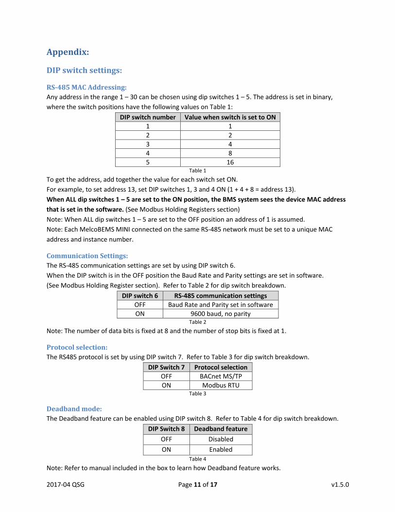
DIP switch settings:
RS-485 MAC Addressing:
Any address in the range 1 – 30 can be chosen using dip switches 1 – 5. The address is set in binary,
where the switch positions have the following values on Table 1:
DIP switch number Value when switch is set to ON
1 1
2 2
3 4
4 8
5 16 Table 1
To get the address, add together the value for each switch set ON.
For example, to set address 13, set DIP switches 1, 3 and 4 ON (1 + 4 + 8 = address 13).
When ALL dip switches 1 – 5 are set to the ON position, the BMS system sees the device MAC address
that is set in the software. (See Modbus Holding Registers section)
Note: When ALL dip switches 1 – 5 are set to the OFF position an address of 1 is assumed.
Note: Each MelcoBEMS MINI connected on the same RS-485 network must be set to a unique MAC
address and instance number.
Communication Settings:
The RS-485 communication settings are set by using DIP switch 6.
When the DIP switch is in the OFF position the Baud Rate and Parity settings are set in software.
(See Modbus Holding Register section). Refer to Table 2 for dip switch breakdown.
DIP switch 6 RS-485 communication settings
OFF Baud Rate and Parity set in software
ON 9600 baud, no parity Table 2
Note: The number of data bits is fixed at 8 and the number of stop bits is fixed at 1.
Protocol selection:
The RS485 protocol is set by using DIP switch 7. Refer to Table 3 for dip switch breakdown.
DIP Switch 7 Protocol selection
OFF BACnet MS/TP
ON Modbus RTU Table 3
Deadband mode:
The Deadband feature can be enabled using DIP switch 8. Refer to Table 4 for dip switch breakdown.
DIP Switch 8 Deadband feature
OFF Disabled
ON Enabled
Table 4
Note: Refer to manual included in the box to learn how Deadband feature works.
2017-04 QSG Page 12 of 17 v1.5.0
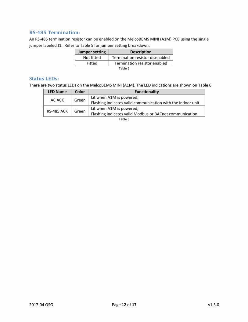
RS-485 Termination: An RS-485 termination resistor can be enabled on the MelcoBEMS MINI (A1M) PCB using the single
jumper labeled J1. Refer to Table 5 for jumper setting breakdown.
Jumper setting Description
Not fitted Termination resistor disenabled
Fitted Termination resistor enabled Table 5
Status LEDs: There are two status LEDs on the MelcoBEMS MINI (A1M). The LED indications are shown on Table 6:
LED Name Color Functionality
AC ACK Green Lit when A1M is powered, Flashing indicates valid communication with the indoor unit.
RS-485 ACK Green Lit when A1M is powered, Flashing indicates valid Modbus or BACnet communication.
Table 6
2017-04 QSG Page 13 of 17 v1.5.0
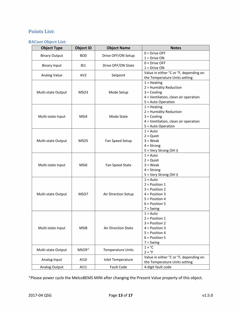
Points List:
BACnet Object List:
Object Type Object ID Object Name Notes
Binary Output BO0 Drive OFF/ON Setup 0 = Drive OFF 1 = Drive ON
Binary Input BI1 Drive OFF/ON State 0 = Drive OFF 1 = Drive ON
Analog Value AV2 Setpoint Value in either °C or °F, depending on the Temperature Units setting
Multi-state Output MSO3 Mode Setup
1 = Heating 2 = Humidity Reduction 3 = Cooling 4 = Ventilation, clean air operation 5 = Auto Operation
Multi-state Input MSI4 Mode State
1 = Heating 2 = Humidity Reduction 3 = Cooling 4 = Ventilation, clean air operation 5 = Auto Operation
Multi-state Output MSO5 Fan Speed Setup
1 = Auto 2 = Quiet 3 = Weak 4 = Strong 5 = Very Strong (SH i)
Multi-state Input MSI6 Fan Speed State
1 = Auto 2 = Quiet 3 = Weak 4 = Strong 5 = Very Strong (SH i)
Multi-state Output MSO7 Air Direction Setup
1 = Auto 2 = Position 1 3 = Position 2 4 = Position 3 5 = Position 4 6 = Position 5 7 = Swing
Multi-state Input MSI8 Air Direction State
1 = Auto 2 = Position 1 3 = Position 2 4 = Position 3 5 = Position 4 6 = Position 5 7 = Swing
Multi-state Output MSO9* Temperature Units 1 = °C 2 = °F
Analog Input AI10 Inlet Temperature Value in either °C or °F, depending on the Temperature Units setting
Analog Output AI11 Fault Code 4-digit fault code
*Please power cycle the MelcoBEMS MINI after changing the Present Value property of this object.
2017-04 QSG Page 14 of 17 v1.5.0
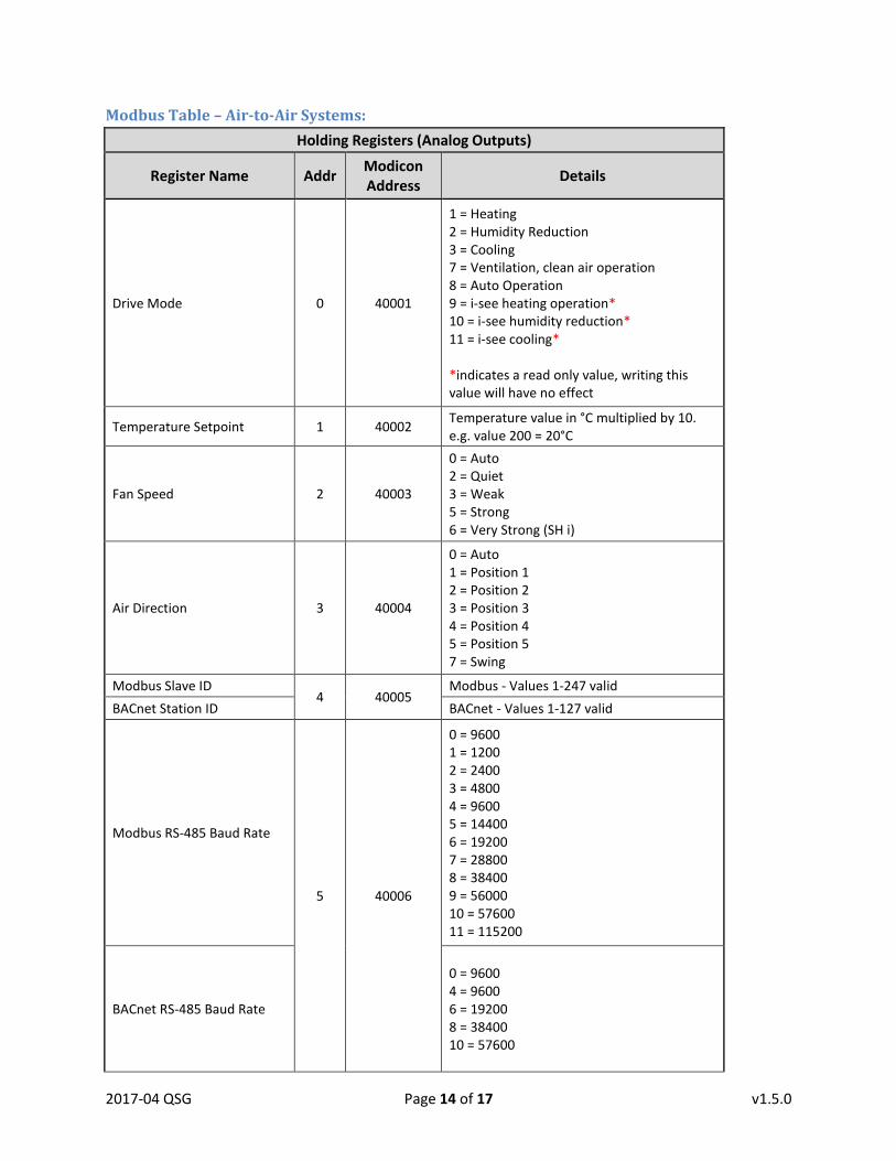
Modbus Table – Air-to-Air Systems:
Holding Registers (Analog Outputs)
Register Name Addr Modicon Address
Details
Drive Mode 0 40001
1 = Heating 2 = Humidity Reduction 3 = Cooling 7 = Ventilation, clean air operation 8 = Auto Operation 9 = i-see heating operation* 10 = i-see humidity reduction* 11 = i-see cooling* *indicates a read only value, writing this value will have no effect
Temperature Setpoint 1 40002 Temperature value in °C multiplied by 10. e.g. value 200 = 20°C
Fan Speed 2 40003
0 = Auto 2 = Quiet 3 = Weak 5 = Strong 6 = Very Strong (SH i)
Air Direction 3 40004
0 = Auto 1 = Position 1 2 = Position 2 3 = Position 3 4 = Position 4 5 = Position 5 7 = Swing
Modbus Slave ID 4 40005
Modbus - Values 1-247 valid
BACnet Station ID BACnet - Values 1-127 valid
Modbus RS-485 Baud Rate
5 40006
0 = 9600 1 = 1200 2 = 2400 3 = 4800 4 = 9600 5 = 14400 6 = 19200 7 = 28800 8 = 38400 9 = 56000 10 = 57600 11 = 115200
BACnet RS-485 Baud Rate
0 = 9600 4 = 9600 6 = 19200 8 = 38400 10 = 57600

2017-04 QSG Page 15 of 17 v1.5.0
Holding Registers (Analog Outputs)
Register Name Addr Modicon Address
Details
RS-485 Parity Type 6 40007 0 = None 1 = Even 2 = Odd
Drive ON/OFF 7 40008 0 = Drive OFF 1 = Drive ON
Room Temperature [READ ONLY]
8 40009 Temperature value in °C multiplied by 10. e.g. value 200 = 20°C
Fault Code (hex) [READ ONLY]
9 40010
0x8000 = No error 0x6999 = Bad communication with indoor unit (Refer to indoor unit documentation for description of other fault code values)
Firmware Version [READ ONLY]
10 40011 A1M firmware version
Modbus Comms Counter [READ ONLY]
11 40012
Value of a counter which increments upon every valid Modbus communication received. Value is automatically reset to zero when value exceeds 65535.
Fault Code (decimal) [READ ONLY]
12 40013
8000 = No error 6999 = Bad communication with indoor unit (Refer to indoor unit documentation for description of other fault code values)
System Type Detected [READ ONLY]
13 40014 0 = ATA 1 = ATW
Deadband Enabled State [READ ONLY]
14 40015 0 = Deadband disabled (DIP switch 8 OFF) 1 = Deadband enabled (DIP switch 8 ON)
BMS Room Temp (signed) 15 40016 Signed temperature value in °C multiplied by 10. 0xFF9C = -10°C…0x01F4 = 50°C
BMS Room Temp 16 40017 Signed temperature value in °C multiplied by 10. 0 = 0°C…500 = 50°C
BMS Virtual Setpoint 17 40018 Signed temperature value in °C multiplied by 10. 100 = 10°C…400 = 40°C
Deadband Heating Setpoint 18 40019 Temperature in °C (default in 19°C). Value must be at least 2°C lower than the Deadband Cooling Setpoint.
Deadband Cooling Setpoint 19 40020 Temperature in °C (default in 23°C). Value must be at least 2°C higher than the Deadband Heating Setpoint.
2017-04 QSG Page 16 of 17 v1.5.0
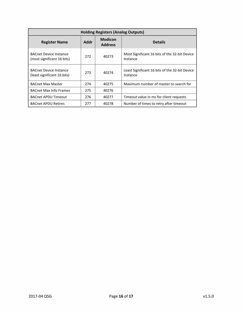
Holding Registers (Analog Outputs)
Register Name Addr Modicon Address
Details
BACnet Device Instance (most significant 16 bits)
272 40273 Most Significant 16 bits of the 32-bit Device Instance
BACnet Device Instance (least significant 16 bits)
273 40274 Least Significant 16 bits of the 32-bit Device Instance
BACnet Max Master 274 40275 Maximum number of master to search for
BACnet Max Info Frames 275 40276
BACnet APDU Timeout 276 40277 Timeout value in ms for client requests
BACnet APDU Retires 277 40278 Number of times to retry after timeout
2017-04 QSG Page 17 of 17 v1.5.0
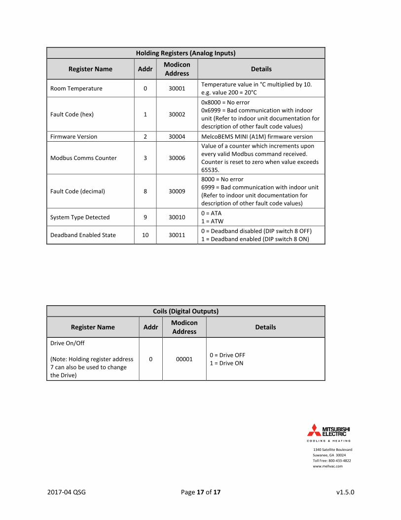
Holding Registers (Analog Inputs)
Register Name Addr Modicon Address
Details
Room Temperature 0 30001 Temperature value in °C multiplied by 10. e.g. value 200 = 20°C
Fault Code (hex) 1 30002
0x8000 = No error 0x6999 = Bad communication with indoor unit (Refer to indoor unit documentation for description of other fault code values)
Firmware Version 2 30004 MelcoBEMS MINI (A1M) firmware version
Modbus Comms Counter 3 30006
Value of a counter which increments upon every valid Modbus command received. Counter is reset to zero when value exceeds 65535.
Fault Code (decimal) 8 30009
8000 = No error 6999 = Bad communication with indoor unit (Refer to indoor unit documentation for description of other fault code values)
System Type Detected 9 30010 0 = ATA 1 = ATW
Deadband Enabled State 10 30011 0 = Deadband disabled (DIP switch 8 OFF) 1 = Deadband enabled (DIP switch 8 ON)
Coils (Digital Outputs)
Register Name Addr Modicon Address
Details
Drive On/Off (Note: Holding register address 7 can also be used to change the Drive)
0 00001 0 = Drive OFF 1 = Drive ON
1340 Satellite Boulevard
Suwanee, GA 30024
Toll Free: 800-433-4822
www.mehvac.com