Embed Size (px)
Citation preview

BACKHOE MANUAL
Owner s manual
TABLE OF CONTENTS
PAGE
GENERAL INFORMATION 4
CHAPTER 1. SAFETY PRECAUTIONS 5
1.1 SAFETY 5
1.2 SAFETY PRECAUTIONS 6
CHAPTER 2. SAFETY DECALS 8
CHAPTER 3. BACKHOE SPECIFICATIONS 11
3.1 DIGGING DIAGRAM 12
3.2 HYDRAULIC SYSTEM MAIN COMPONENT 13
3.3 BACKHOE MAIN COMPONENTS 14
CHAPTER 4. ASSEMBLY INSTRUCTIONS 15
CHAPTER 5. TRACTOR PREPARATION 35
5.1 HYDRAULIC SYSTEM 35
5.2 TYRE INFLATION 35
5.3 WHEEL TREAD SETTINGS 35
5.4 ATTACHMENT 36
5.5 COUNTER WEIGHT 36
CHAPTER 6. BACKHOE OPERATION 37
6.1 PRECAUTIONARY NOTE 37
6.2 INITIAL BACKHOE OPERATION 39
6.3 COLD WEATHER OPERATION 39

6.4 BACKHOE HYDRAULIC CONTROLS 40
6.5 STABILIZER CLIPS 41
6.6 OPERATING HYDRAULIC SIDE SHIFT 41
CHAPTER 7. MAINTENANCE 44
CHAPTER 8. TROUBLE SHOOTING 47
GENERAL INFORMATION
INTRODUCTION:
The purpose of this manual is to assist you in maintaining and operating your backhoe. Read it
carefully, it provides information and instructions that will help you achieve years of reliable
performance. Some information may be general in nature due to unknown and varying conditions.
However, through experience and these instructions, you should be able to develop operating
procedures suitable to your particular situation.
“Right” and “Left” as used throughout this manual are determined by position operator is facing when
in use.
The photos, illustrations and data used in this manual are current at the time of printing, but due to
possible in-line production changes, your machine may vary slightly in detail. The manufacturer
reserves the right to redesign the machine as may be necessary without notification.
Important:
Illustrations used in this manual may not show all safety equipment that is recommended to ensure
safe operation of tractor and backhoe. Refer to the Safety Precautions section of this manual for
information concerning safety, consult your dealer for further information.

1 Safety Precautions
1.1 SAFETY Understand that your safety and the safety of other persons is measured by how you service and
operate this Backhoe.
Know the position and operations of all controls before you they operate. Make sure you check all
controls in safe area before starting.
Read this manual completely and thoroughly and make sure you understand all controls. All
equipment has a limit. Make sure you are aware of the stability and load characteristics of this
Backhoe before you begin operation.
The Safety Information given in this manual does not replace any safety codes, insurance needs,
federal, state and local laws. Make sure your machine has the correct equipment required by your
local laws and regulations.
This safety alert symbol indicates important safety message
in this manual. When you see this symbol, carefully read
the message that followings and be alert to the possibility of
personal injury or death.
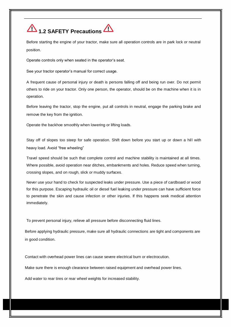
1.2 SAFETY Precautions
Before starting the engine of your tractor, make sure all operation controls are in park lock or neutral
position.
Operate controls only when seated in the operator’s seat.
See your tractor operator’s manual for correct usage.
A frequent cause of personal injury or death is persons falling off and being run over. Do not permit
others to ride on your tractor. Only one person, the operator, should be on the machine when it is in
operation.
Before leaving the tractor, stop the engine, put all controls in neutral, engage the parking brake and
remove the key from the ignition.
Operate the backhoe smoothly when lowering or lifting loads.
Stay off of slopes too steep for safe operation. Shift down before you start up or down a hil l with
heavy load. Avoid “free wheeling”
Travel speed should be such that complete control and machine stability is maintained at all times.
Where possible, avoid operation near ditches, embankments and holes. Reduce speed when turning,
crossing slopes, and on rough, slick or muddy surfaces.
Never use your hand to check for suspected leaks under pressure. Use a piece of cardboard or wood
for this purpose. Escaping hydraulic oil or diesel fuel leaking under pressure can have sufficient force
to penetrate the skin and cause infection or other injuries. If this happens seek medical attention
immediately.
To prevent personal injury, relieve all pressure before disconnecting fluid lines.
Before applying hydraulic pressure, make sure all hydraulic connections are tight and components are
in good condition.
Contact with overhead power lines can cause severe electrical burn or electrocution.
Make sure there is enough clearance between raised equipment and overhead power lines.
Add water to rear tires or rear wheel weights for increased stability.

A backhoe attachment should be transported in a low position at slow ground speeds. Make turns
slowly and use the tractor brakes cautiously. A loaded attachment in the raised position alters the
center of gravity location of the machine and increases the possibility of mishaps.
Do not stand, walk or work under a raised backhoe attachment unless it is securely blocked or
mechanically in position. Accidental movement of a control lever or leak in the hydraulic system could
cause the backhoe to drop, or attachment to dump, causing severe injury.
Make sure all parked backhoe on stands are on a hard level surface with all safety devices engaged to
prevent backhoe from falling and being damaged or injuring someone.
When using a backhoe, be alert of bucket, boom and arm position at all times.
Only operators who have been specially trained in backhoe operation and fully understand this
manual can operate the backhoe.
Keep hands, feet and clothing away from all moving parts. Wear close fitting clothing and appropriate
safety equipment (Which includes, steel cap shoes, protective gloves, hard hat, safety glasses and
dusk mask). Prolonged exposure to loud noise can damage hearing. Wear suitable approved hearing
protection such as ear muffs or plugs. Operating equipment safely requires your full attention. Do not
wear radio or music headphones. Secure hair above shoulder length.
You must be in good physical and mental health to operate the backhoe safely. Do not operate the
backhoe when you are ill, fatigued or under the influence of any substance or medication that could
affect your vision, co-ordination or judgment.
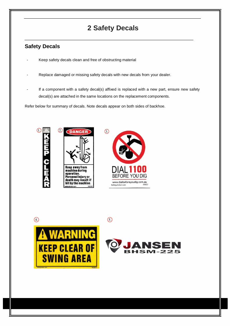
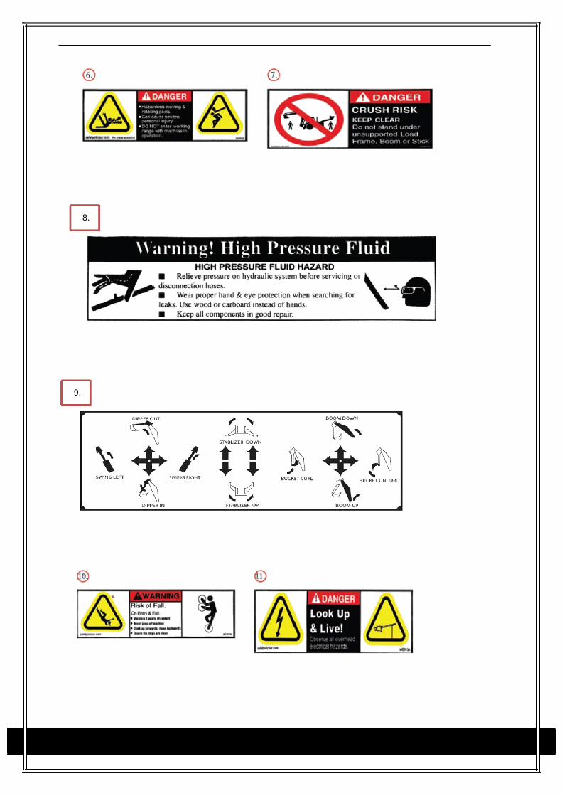
2 Safety Decals
Safety Decals - Keep safety decals clean and free of obstructing material
- Replace damaged or missing safety decals with new decals from your dealer.
- If a component with a safety decal(s) affixed is replaced with a new part, ensure new safety
decal(s) are attached in the same locations on the replacement components.
Refer below for summary of decals. Note decals appear on both sides of backhoe.
8.
9.


3 Backhoe Specifications
Model BHM-175 BHM-195 BHM-225
Dimension (L×W×H) (mm)
Structure weight (kg) 520 550 750
Max digging depth (m) A 2.6 2.9 3.3
Max digging radius (m) B 1.75 1.85 2.25
Max height (m) C 3.12 3.17 3.45
Max unloading height (m) D 1.8 2 2.3
Stabilizer width (m) 1.7 1.7 1.7
Swing angle for boom 180 180 180
Bucket turning angle 195 195 203
Bucket capacity of standard bucket (m³) 0.02 0.025 0.035
Bucket width (mm) 300 400 500
Bucket Digging Force (kg) 1100 1100 1700
Dipper Arm Digging Force (kg) 850 850 1100
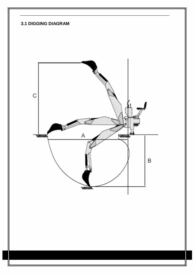
3.1 DIGGING DIAGRAM
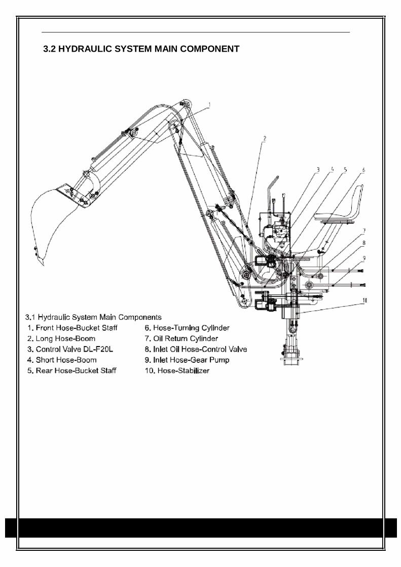
3.2 HYDRAULIC SYSTEM MAIN COMPONENT
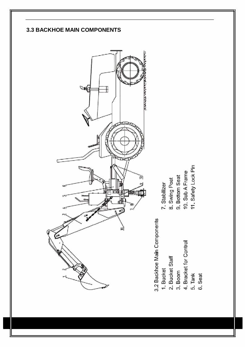
3.3 BACKHOE MAIN COMPONENTS
4 Assembly instructions
Read and ensure you understand the full
assembly instructions before you begin
construction. Only remove the transport
frame when the assembly instructions say
to do so.
The machine is delivered from the factory in
transport configuration. Always use suitably
sized tools, appliances and lifting equipment
with adequate power for assembly. Two
people are always required for lifting,
moving and assembling the machine. Wear
suitable protective clothing such as safety
shoes and protective gloves. Check that all
screws and nuts are fitted correctly when
assembling the machine. Take care when
opening the accompanying boxes as hard
additional parts are inside.
Before starting to assemble the machine,
please observe the following instructions:
- Clear the area beforehand of people
standing in the vicinity, particularly
children.
- Use a forklift truck to move or lift
the palette/machine.
- Keep the load close to the ground.
- Move the machine to the assembly
site
- Ensure there is enough room to
safely assemble the machine and
access the machine from all sides.
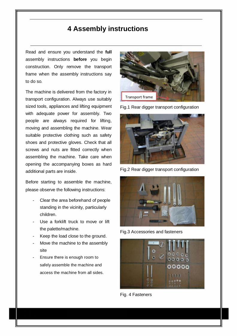
Transport frame
Fig.1 Rear digger transport configuration
Fig.2 Rear digger transport configuration
Fig.3 Accessories and fasteners
Fig. 4 Fasteners
Important notices:
Before beginning assembly, read the full
assembly instructions through and
familiarise yourself with the individual
stages of assembly in advance. This is
very necessary as the assembly stages
build on each other logically and failing to
follow the order that the steps go in can lead
to components of the rear digger being
damaged.
Make sure that the rear digger is standing
securely at all times during assembly. This
applies especially if the rear digger has not
yet been attached to the tractor’s 3-point
chassis.
Important: Only loosen the screws on the
transport frame when the assembly
instructions say to do so!
The rear digger is delivered without
hydraulic fluid. Further information on the
necessary advance filling and monitoring of
the hydraulic fluid level is given later in these
operating instructions. Never operate the rear
digger without enough hydraulic fluid.
In rare cases you may find that the control
directions on the operating unit label are not
in compliance with the actual directions for
hydraulic movements when operating the
digger.
When you first operate the digger, move the
lever very slowly and keep constant control
of the directions of movement. This also
applies to the first removal and fixing of the
transport frame to manoeuvre the rear
digger to a safe assembly position during
initial assembly.
Always secure the rear digger with the
transport frame between different places of
use to avoid accidents.
Remember not to remove the lower
transport frame before the instructions say
to do so to categorically rule out the chance
of the rear digger falling over and thereby
avoid serious injuries and accidents.
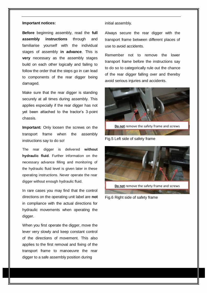
Do not remove the safety frame and screws
Fig.5 Left side of safety frame
Do not remove the safety frame and screws
Fig.6 Right side of safety frame
Assembly
1. Testing
Check all of the hydraulic pipes for correct
assembly, leakage and correct position.
Check all screws for correct and secure
positioning.
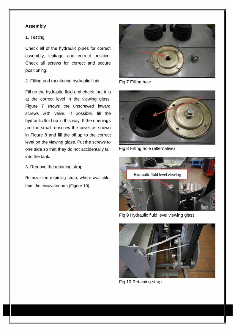
2. Filling and monitoring hydraulic fluid
Fill up the hydraulic fluid and check that it is
at the correct level in the viewing glass.
Figure 7 shows the unscrewed inward
screws with valve. If possible, fill the
hydraulic fluid up in this way. If the openings
are too small, unscrew the cover as shown
in Figure 8 and fill the oil up to the correct
level on the viewing glass. Put the screws to
one side so that they do not accidentally fall
into the tank.
3. Remove the retaining strap
Remove the retaining strap, where available,
from the excavator arm (Figure 10).
Fig.7 Filling hole
Fig.8 Filling hole (alternative)
Hydraulic fluid level viewing
Fig.9 Hydraulic fluid level viewing glass
Fig.10 Retaining strap
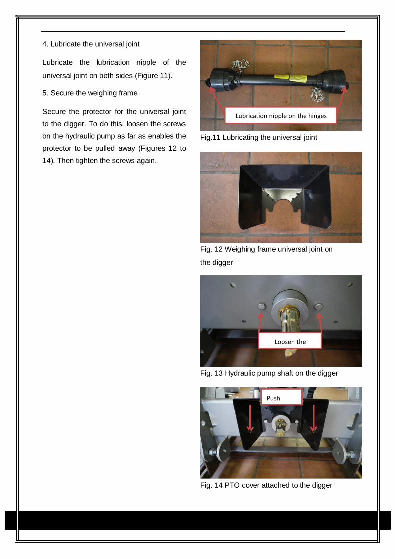
4. Lubricate the universal joint
Lubricate the lubrication nipple of the
universal joint on both sides (Figure 11).
5. Secure the weighing frame
Secure the protector for the universal joint
to the digger. To do this, loosen the screws
on the hydraulic pump as far as enables the
protector to be pulled away (Figures 12 to
14). Then tighten the screws again.
Lubrication nipple on the hinges
Fig.11 Lubricating the universal joint
Fig. 12 Weighing frame universal joint on
the digger
Loosen the
Fig. 13 Hydraulic pump shaft on the digger
Push
Fig. 14 PTO cover attached to the digger
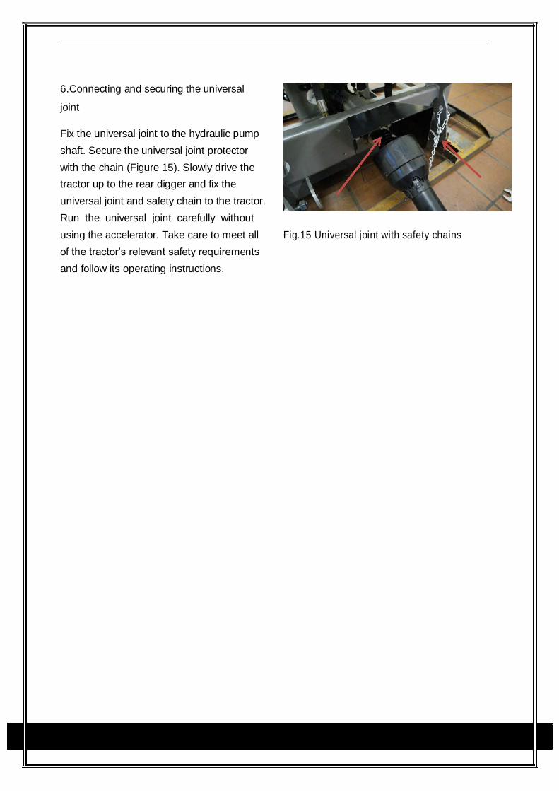
6.Connecting and securing the universal
joint
Fix the universal joint to the hydraulic pump
shaft. Secure the universal joint protector
with the chain (Figure 15). Slowly drive the
tractor up to the rear digger and fix the
universal joint and safety chain to the tractor.
Run the universal joint carefully without
using the accelerator. Take care to meet all Fig.15 Universal joint with safety chains
of the tractor’s relevant safety requirements
and follow its operating instructions.
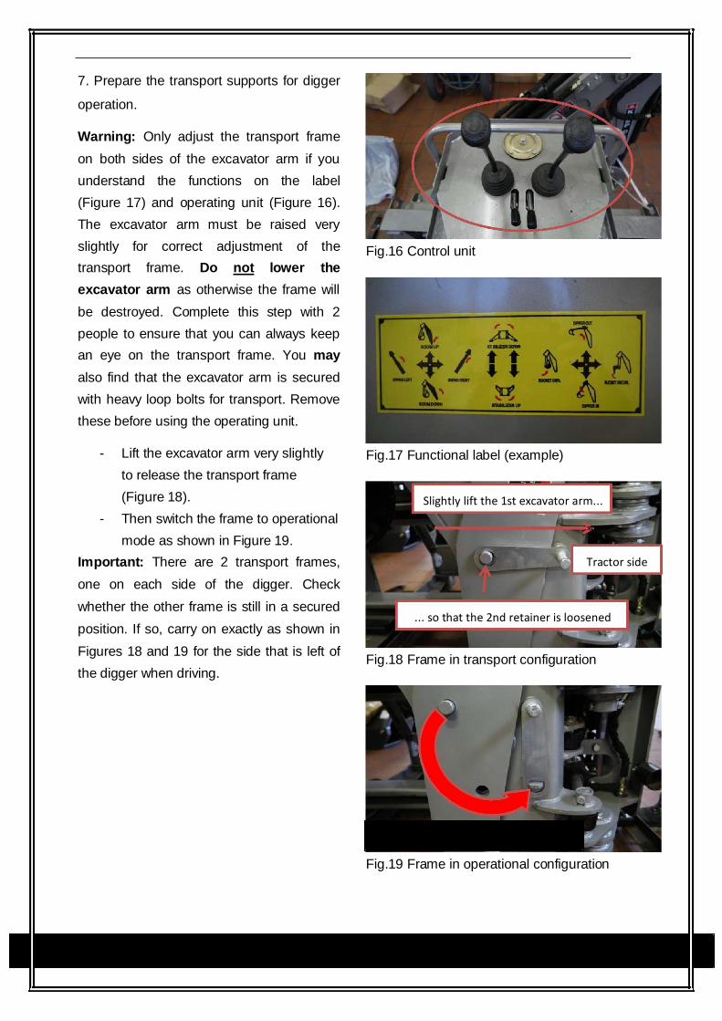
7. Prepare the transport supports for digger
operation.
Warning: Only adjust the transport frame
on both sides of the excavator arm if you
understand the functions on the label
(Figure 17) and operating unit (Figure 16).
The excavator arm must be raised very
slightly for correct adjustment of the
transport frame. Do not lower the
excavator arm as otherwise the frame will
be destroyed. Complete this step with 2
people to ensure that you can always keep
an eye on the transport frame. You may
also find that the excavator arm is secured
with heavy loop bolts for transport. Remove
these before using the operating unit.
- Lift the excavator arm very slightly
to release the transport frame
(Figure 18).
- Then switch the frame to operational
mode as shown in Figure 19.
Important: There are 2 transport frames,
one on each side of the digger. Check
whether the other frame is still in a secured
position. If so, carry on exactly as shown in
Figures 18 and 19 for the side that is left of
the digger when driving.
Fig.16 Control unit
Fig.17 Functional label (example)
Slightly lift the 1st excavator arm...
Tractor side
... so that the 2nd retainer is loosened
Fig.18 Frame in transport configuration
Switching to operational configuration
Fig.19 Frame in operational configuration
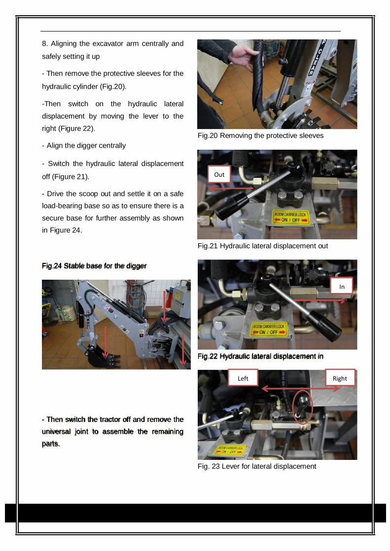
8. Aligning the excavator arm centrally and
safely setting it up
- Then remove the protective sleeves for the
hydraulic cylinder (Fig.20).
-Then switch on the hydraulic lateral
displacement by moving the lever to the
right (Figure 22).
- Align the digger centrally
- Switch the hydraulic lateral displacement
off (Figure 21).
- Drive the scoop out and settle it on a safe
load-bearing base so as to ensure there is a
secure base for further assembly as shown
in Figure 24.
Fig.24 Stable base for the digger
Fig.20 Removing the protective sleeves
Out
Fig.21 Hydraulic lateral displacement out
In
Fig.22 Hydraulic lateral displacement in
Left Right
- Then switch the tractor off and remove the
universal joint to assemble the remaining
parts.
Fig. 23 Lever for lateral displacement
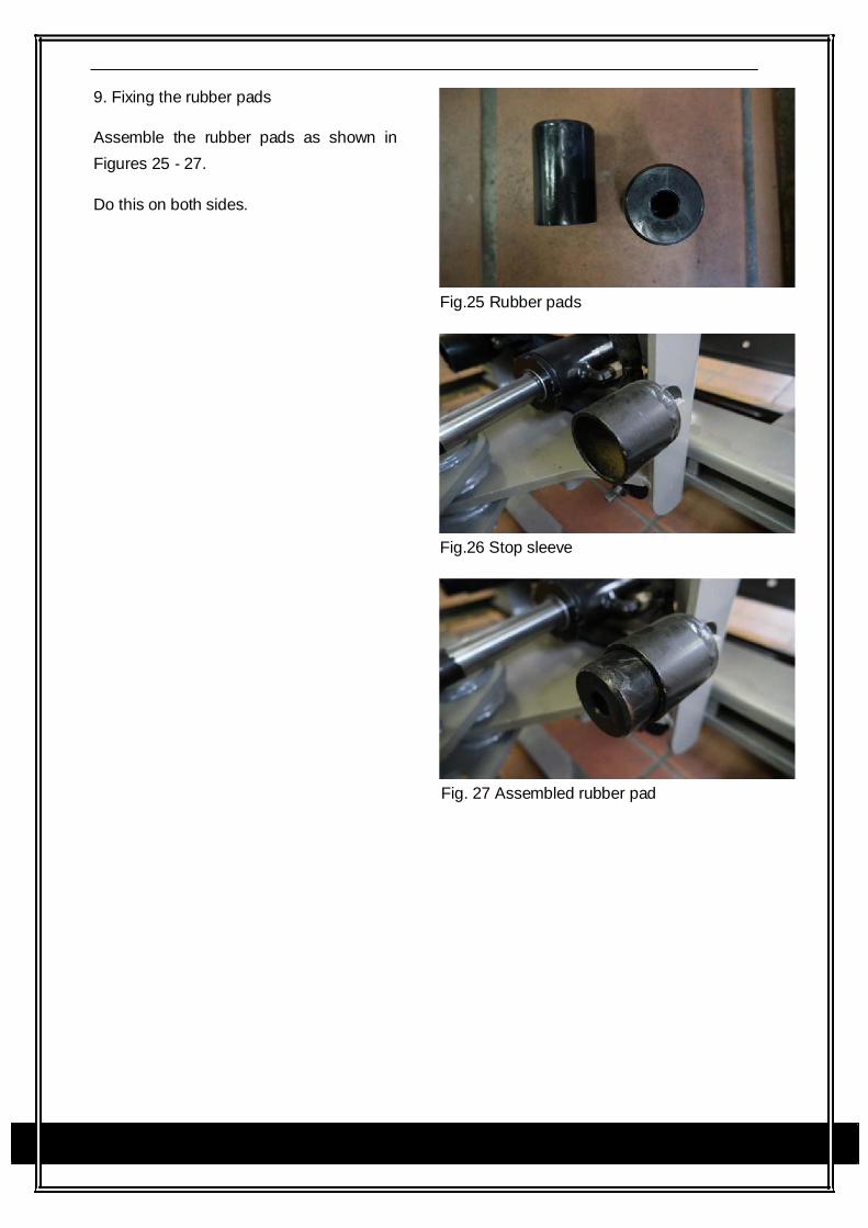
9. Fixing the rubber pads
Assemble the rubber pads as shown in Figures 25 - 27.
Do this on both sides.
Fig.25 Rubber pads
Fig.26 Stop sleeve
Fig. 27 Assembled rubber pad
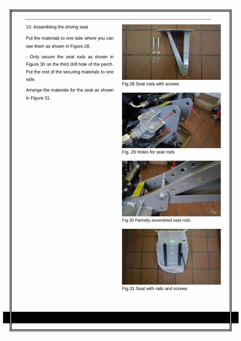
10. Assembling the driving seat
Put the materials to one side where you can
see them as shown in Figure 28.
- Only secure the seat rods as shown in
Figure 30 on the third drill hole of the perch.
Put the rest of the securing materials to one
side.
Arrange the materials for the seat as shown
in Figure 31.
Fig.28 Seat rods with screws
Fig. 29 Holes for seat rods
Fig.30 Partially assembled seat rods
Fig.31 Seat with rails and screws
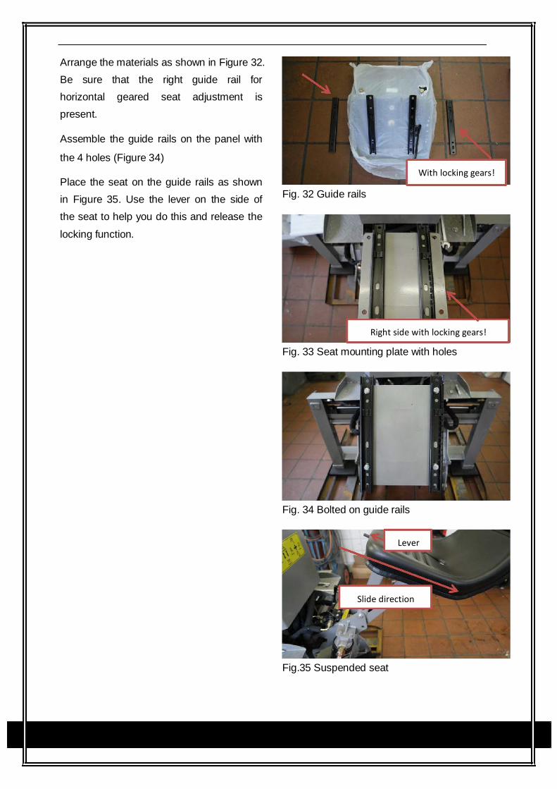
Arrange the materials as shown in Figure 32.
Be sure that the right guide rail for
horizontal geared seat adjustment is
present.
Assemble the guide rails on the panel with
the 4 holes (Figure 34)
Place the seat on the guide rails as shown
in Figure 35. Use the lever on the side of
the seat to help you do this and release the
locking function.
With locking gears!
Fig. 32 Guide rails
Right side with locking gears!
Fig. 33 Seat mounting plate with holes
Fig. 34 Bolted on guide rails
Lever
Slide direction
Fig.35 Suspended seat
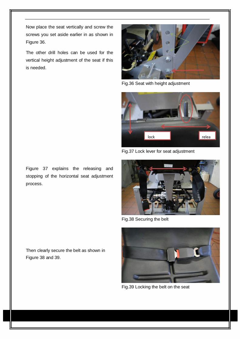
Now place the seat vertically and screw the
screws you set aside earlier in as shown in
Figure 36.
The other drill holes can be used for the
vertical height adjustment of the seat if this
is needed.
Fig.36 Seat with height adjustment
lock relea
Fig.37 Lock lever for seat adjustment
Figure 37 explains the releasing and
stopping of the horizontal seat adjustment
process.
Fig.38 Securing the belt
Then clearly secure the belt as shown in Figure 38 and 39.
Fig.39 Locking the belt on the seat
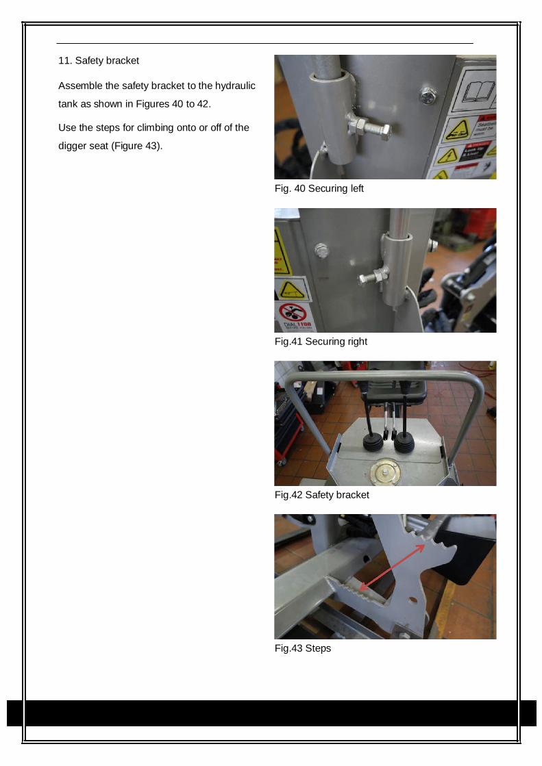
11. Safety bracket
Assemble the safety bracket to the hydraulic
tank as shown in Figures 40 to 42.
Use the steps for climbing onto or off of the
digger seat (Figure 43).
Fig. 40 Securing left
Fig.41 Securing right
Fig.42 Safety bracket
Fig.43 Steps
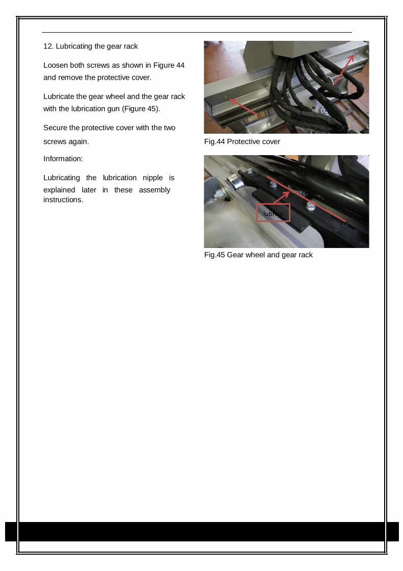
12. Lubricating the gear rack
Loosen both screws as shown in Figure 44
and remove the protective cover.
Lubricate the gear wheel and the gear rack
with the lubrication gun (Figure 45).
Secure the protective cover with the two
screws again. Fig.44 Protective cover
Information:
Lubricating the lubrication nipple is
explained later in these assembly
instructions.
lubrica
Fig.45 Gear wheel and gear rack
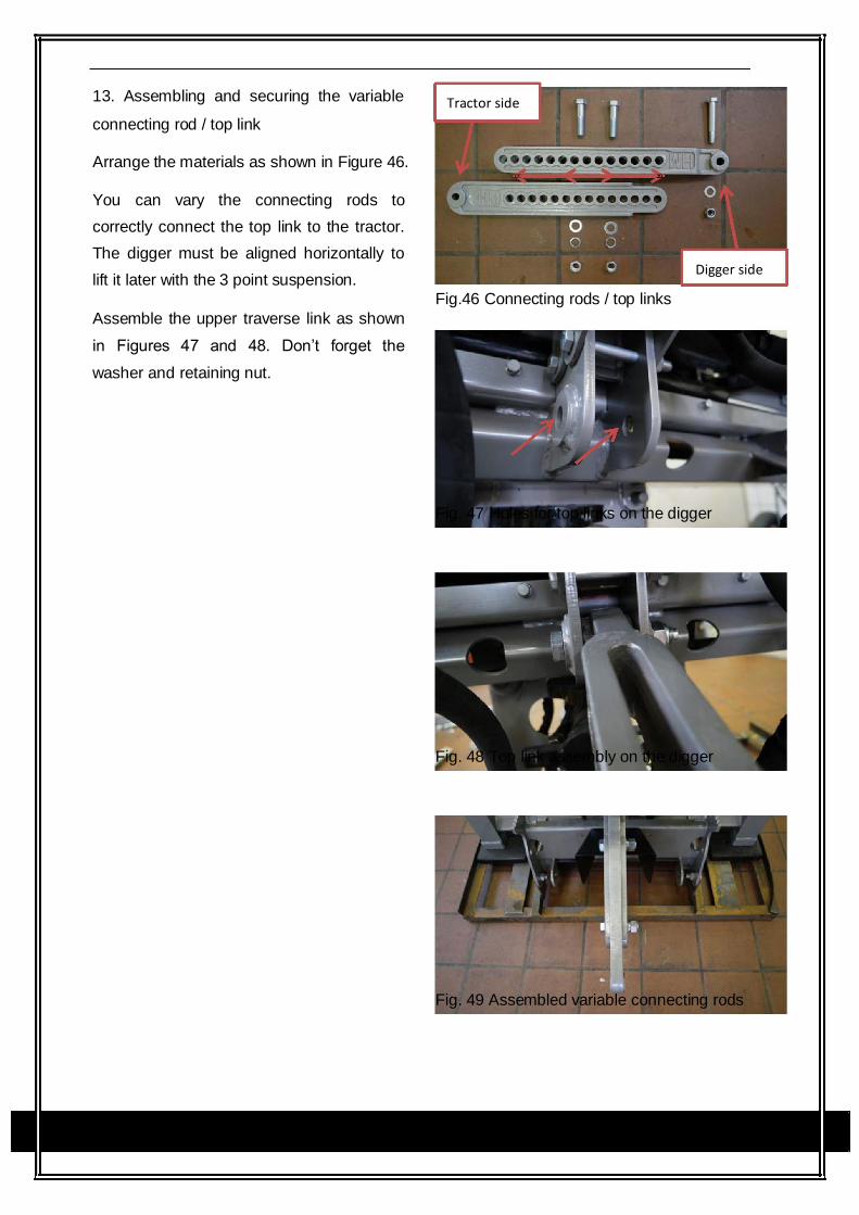
13. Assembling and securing the variable
connecting rod / top link
Arrange the materials as shown in Figure 46.
You can vary the connecting rods to
correctly connect the top link to the tractor.
The digger must be aligned horizontally to
lift it later with the 3 point suspension.
Assemble the upper traverse link as shown
in Figures 47 and 48. Don’t forget the
washer and retaining nut.
Tractor side
Digger side
Fig.46 Connecting rods / top links
Fig. 47 Holes for top links on the digger
Fig. 48 Top link assembly on the digger
Fig. 49 Assembled variable connecting rods
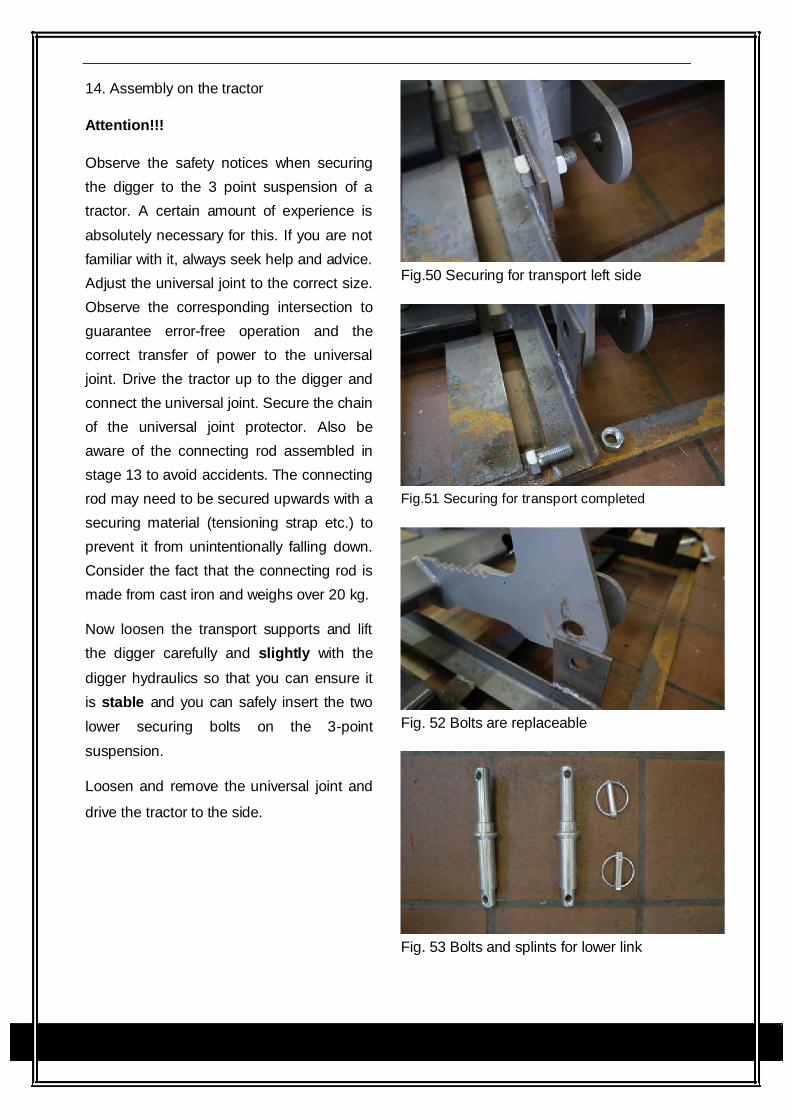
14. Assembly on the tractor
Attention!!!
Observe the safety notices when securing
the digger to the 3 point suspension of a
tractor. A certain amount of experience is
absolutely necessary for this. If you are not
familiar with it, always seek help and advice.
Adjust the universal joint to the correct size.
Observe the corresponding intersection to
guarantee error-free operation and the
correct transfer of power to the universal
joint. Drive the tractor up to the digger and
connect the universal joint. Secure the chain
of the universal joint protector. Also be
aware of the connecting rod assembled in
stage 13 to avoid accidents. The connecting
rod may need to be secured upwards with a
securing material (tensioning strap etc.) to
prevent it from unintentionally falling down.
Consider the fact that the connecting rod is
made from cast iron and weighs over 20 kg.
Now loosen the transport supports and lift
the digger carefully and slightly with the
digger hydraulics so that you can ensure it
is stable and you can safely insert the two
lower securing bolts on the 3-point
suspension.
Loosen and remove the universal joint and
drive the tractor to the side.
Fig.50 Securing for transport left side
Fig.51 Securing for transport completed
Fig. 52 Bolts are replaceable
Fig. 53 Bolts and splints for lower link
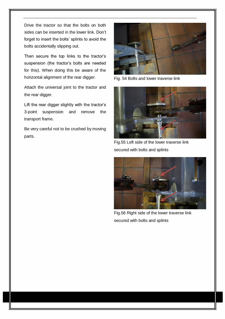
Drive the tractor so that the bolts on both
sides can be inserted in the lower link. Don’t
forget to insert the bolts’ splints to avoid the
bolts accidentally slipping out.
Then secure the top links to the tractor’s
suspension (the tractor’s bolts are needed
for this). When doing this be aware of the
horizontal alignment of the rear digger.
Attach the universal joint to the tractor and
the rear digger.
Lift the rear digger slightly with the tractor’s
3-point suspension and remove the
transport frame.
Be very careful not to be crushed by moving
parts.
Fig. 54 Bolts and lower traverse link
Fig.55 Left side of the lower traverse link
secured with bolts and splints
Fig.56 Right side of the lower traverse link
secured with bolts and splints
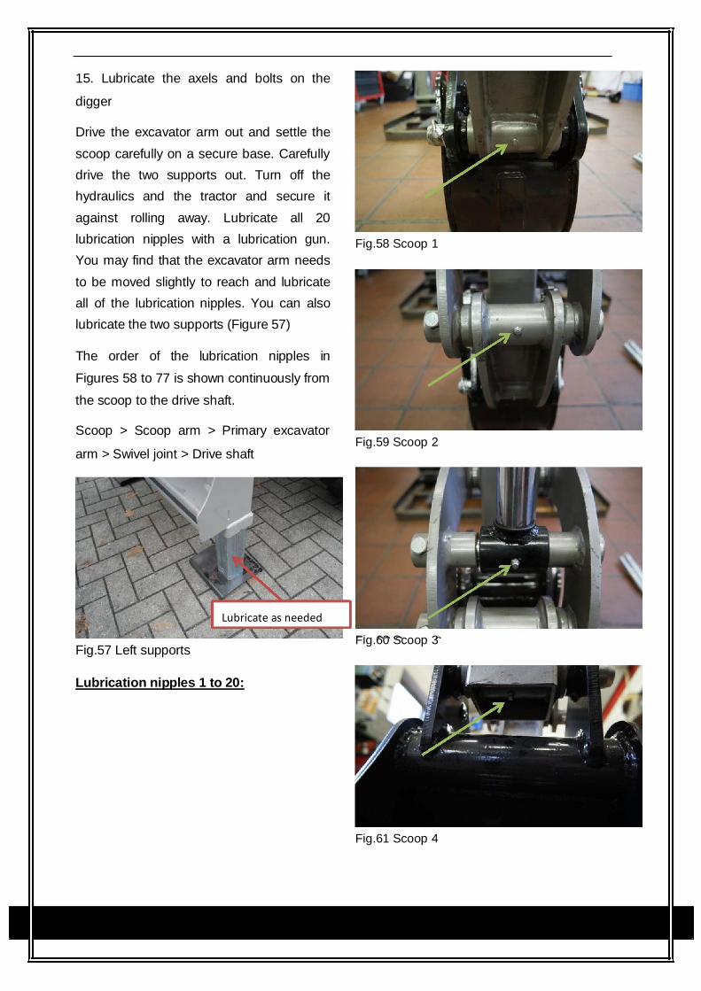
15. Lubricate the axels and bolts on the
digger
Drive the excavator arm out and settle the
scoop carefully on a secure base. Carefully
drive the two supports out. Turn off the
hydraulics and the tractor and secure it
against rolling away. Lubricate all 20
lubrication nipples with a lubrication gun.
You may find that the excavator arm needs
to be moved slightly to reach and lubricate
all of the lubrication nipples. You can also
lubricate the two supports (Figure 57)
The order of the lubrication nipples in
Figures 58 to 77 is shown continuously from
the scoop to the drive shaft.
Scoop > Scoop arm > Primary excavator
arm > Swivel joint > Drive shaft
Lubricate as needed
Fig.57 Left supports
Lubrication nipples 1 to 20:
Fig.58 Scoop 1
Fig.59 Scoop 2
Fig.60 Scoop 3
Fig.61 Scoop 4
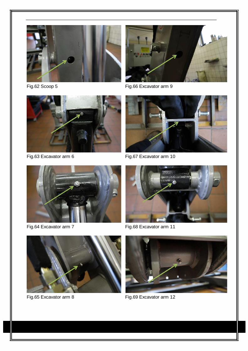
Fig.62 Scoop 5 Fig.66 Excavator arm 9
Fig.63 Excavator arm 6 Fig.67 Excavator arm 10
Fig.64 Excavator arm 7 Fig.68 Excavator arm 11
Fig.65 Excavator arm 8 Fig.69 Excavator arm 12
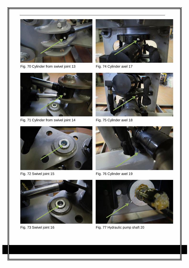
Fig. 70 Cylinder from swivel joint 13 Fig. 74 Cylinder axel 17
Fig. 71 Cylinder from swivel joint 14 Fig. 75 Cylinder axel 18
Fig. 72 Swivel joint 15 Fig. 76 Cylinder axel 19
Fig. 73 Swivel joint 16 Fig. 77 Hydraulic pump shaft 20

16. Testing the hydraulic fluid and correcting
the oil level
Before you use the digger, check all the
hydraulic pipes for leaks and ease of
movement. Be careful not to crush or
damage the hydraulic pipes when operating
the digger. Sit the rear digger horizontally
straight to enable the oil level to be correctly
filled up.
Run through all of the functions of all
hydraulic components of the digger (drive it
all the way in and all the way out). Do this
three times for each function of the digger
(scoops, excavator arms, lateral
displacement, support) to completely fill the
hydraulic circuit with fluid.
Then check the hydraulic fluid level of the
hydraulic fluid tank and, if necessary, fill as
described in step 2 of these assembly
instructions.
5 Tractor Preparation
Caution: Do not exceed the manufacturer’s rating for maximum gross vehicle weight.
Refer to Operator’s Manual provided with tractor.
Caution: Certain Specific conditions may not permit safe use of backhoe at
backhoe rating or may require more careful restricted operation at the rated load.
5.1 Hydraulic System
Models BHM / BHSM Series These Models are driven by the tractors Power Take Off, and are fitted with an in-built Hydraulic pump
and tank. Check fluid level daily, ensure PTO shaft is greased and change hydraulic filter.
Caution: The tractor / backhoe must only be operated with all safety
equipment properly installed
5.2 Tyre Inflation Front Tyres must be maintained at the maximum recommended inflation to maintain normal tyre
profile with the added weight of backhoe/material.
5.3 Wheel Tread Settings
Tractor front wheel tread setting must be restricted to wheel tread spacing recommended in the
tractor Operator’s Manual.
5.4 Attachment Ensure your tractor’s 3 point linkage system is fitted with sway chains before attaching the backhoe.
Failure to do can cause the backhoe to swing when travelling potentially causing bodily injury
or machine failure.
Inspect for any worn or damaged parts that are part of the connection between the tractor and
backhoe. Replace if necessary with parts of suitable strength and quality.
5.5 Counter Weight Add recommended ballast (either front weights or front end loader) in tractor’s front-end for increased
stability. Refer to tractor operator’ manual for specific recommendations on counter weighting tractor.
CAUTION: The tractor/backhoe should only be operated with all safety equipment
properly installed. Keep assistants or bystanders a safe distance from the equipment
operating area.
6 Backhoe Operation
CAUTION: The tractor/backhoe should only be operated with all safety equipment
properly installed. Keep assistants or bystanders a safe distance from the equipment
operating area.
6.1 Precautionary Note Read and understand this manual to avoid accidents.
Check the hydraulic fitting lines to be correct and set tightly.
Maintain and repair (if it is needed) the parts or assemblies, check bolts and pins to be sure
they are positioned tightly.
Check tractor with the tractor operator’s manual that it can prepared for operating.
Warn up and operate the tractor and backhoe carefully. Purge any air in the hydraulic lines
and cylinders by fully cycling all cylinders several times.
Check hydraulic level in the tank to the specified level.
Do not operate the hydraulics when not seated in the backhoe operator’s seat
Keep all assistants out of area of operation.
Do not operate rapidly.
Do not allow riders other than the operator to be on the tractor while operating.
Important
Use tractor engine speed that your experience permits. At first set PTO RPM of the tractor to slow.
Do not use the boom, dipper arm, swing and stabilizers to lift, push or pull objects. Use only to
maneuver and operate the bucket.
Important
Practice quickly turning off the engine or stopping the backhoe immediately in case of
an emergency situation.
Important
Do not operate while the rear tractor wheels are off the ground by stabilizer. It is dangerous
to operate the backhoe while rear wheels are off the ground.
Position vehicle so that the backhoe is as near as possible and in such a direction as to
minimize the amount of backhoe turning required to dump.
Keep the unit clean and perform regular service.
We urge you to follow this advice:
1. Read and understand this manual as well as the Tractor Operator’s Manual.
2. Remember and observe the safety Precautions brought to your attention in this manual,
the tractor manual and on the machinery itself.
3. Use good common sense in the everyday operation of this unit. Safety recommendations
can never be all-inclusive and you are responsible for watching out for and avoiding
unsafe conditions.
4. Never exceed the limits of a piece of machinery. If its ability to do a job, or to do so
safely, is in question, don’t try it.
5. Don’t hurry the learning process or take the unit for granted. Ease into it and become
familiar with your new backhoe and tractor.
Caution: When lowing a heavy load, east it downward slowly. Never drop a loaded
attachment and “catch it hydraulically”. Stopping a load after it has gained download
momentum places undue strain on the unit and may cause unnecessary damage to
the backhoe or tractor or even worse, personal injury.
Caution: Before disconnecting hydraulic lines, relieve all hydraulic pressure.
Escaping hydraulic oil under pressure can have sufficient force to penetrate the skin
causing serious personal injury. If injured by escaping hydraulic oil, seek medical
attention immediately.
Caution: Do not operate the backhoe if the fittings are leaking or if the hoses are
damaged. A sudden line burst would cause the boom, or dipper arm bucket to drop
suddenly, causing damage to the tractor or backhoe or injury to personnel.

6.2 Initial Backhoe Operation Before operating the backhoe, fully raise and lower the boom, arm, swing and hydraulic stabilizers two
or three times. Then raise the bucket above the ground and cycle the bucket cylinders three times.
Lower the bucket to the ground. Check the tractor hydraulic oil and the correct oil level.
Caution: Before leaving the machine, stop the engine, remove the key. Place
all controls in neutral, and either set the parking brake or place tractor in park as
equipped.
Always keep cylinders in a retracted position when the backhoe is not in use to guard against
rust and contamination which may cause damage to the cylinder rods or hydraulic system. Also,
lock the swing and boom while tractor is moving and storing for an extended period of time.
6.3 Cold Weather Operation For smooth operation in cold weather, let the tractor warn up. Slowly cycle all of the cylinders
several times to warm the oil in the hydraulic system. The backhoe may operate erratically until
the hydraulic oil has warmed to operating temperatures.
CAUTION: Operate controls only when seated in the operator’s seat with seat belt on.
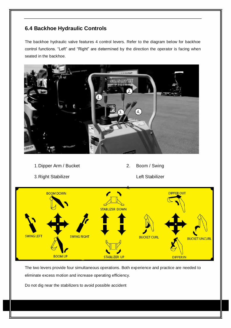
6.4 Backhoe Hydraulic Controls The backhoe hydraulic valve features 4 control levers. Refer to the diagram below for backhoe
control functions. “Left” and “Right” are determined by the direction the operator is facing when
seated in the backhoe.
1. Dipper Arm / Bucket 2. Boom / Swing
3. Right Stabilizer Left Stabilizer
4.
The two levers provide four simultaneous operations. Both experience and practice are needed to
eliminate excess motion and increase operating efficiency.
Do not dig near the stabilizers to avoid possible accident
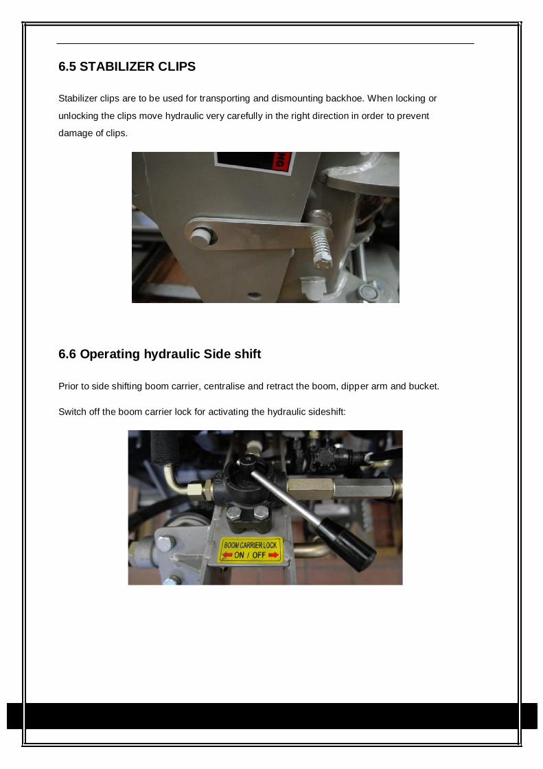
6.5 STABILIZER CLIPS
Stabilizer clips are to be used for transporting and dismounting backhoe. When locking or
unlocking the clips move hydraulic very carefully in the right direction in order to prevent
damage of clips.
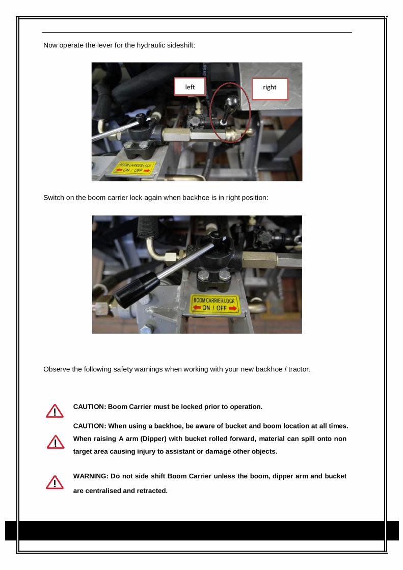
6.6 Operating hydraulic Side shift
Prior to side shifting boom carrier, centralise and retract the boom, dipper arm and bucket.
Switch off the boom carrier lock for activating the hydraulic sideshift:
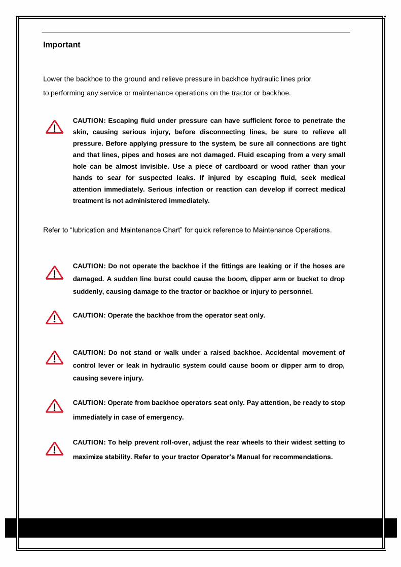
Now operate the lever for the hydraulic sideshift:
left right
Switch on the boom carrier lock again when backhoe is in right position:
Observe the following safety warnings when working with your new backhoe / tractor.
CAUTION: Boom Carrier must be locked prior to operation.
CAUTION: When using a backhoe, be aware of bucket and boom location at all times.
When raising A arm (Dipper) with bucket rolled forward, material can spill onto non
target area causing injury to assistant or damage other objects.
WARNING: Do not side shift Boom Carrier unless the boom, dipper arm and bucket
are centralised and retracted.

WARNING: Do not dig near stabilizers. Ground under stabilizers could collapse.
Make all movements slow and gradual when practicing operation.
CAUTION: Operate from backhoe operators seat only. Pay attention, be ready to stop
immediately in case of emergency.
CAUTION: To help prevent roll-over, adjust the rear wheels to their widest setting to
maximize stability. Refer to your tractor Operator’s Manual for recommendations.

7 Maintenance
Item Service Service Interval
Hydraulic System Oil Level Check Daily / 10 Hours
Hydraulic System Oil / Filter Replace Every 50 Hours
Tyre Inflation Check Weekly / 50 Hours
Backhoe Pivot Points Lubricate / Grease Daily / 10 Hours
Backhoe Hydraulic Lines, Check for leaks, wear Daily / 10 Hours
Hoses, Connections
Boom, Arm, Swing and Check for seepage, service as Daily / 10 Hours
Bucket cylinder rod packings needed
Pivot Pin Bolts and Dust Check, replace if missing Daily / 10 Hours
Covers
Pin Wear Check, replace if necessary Daily / 10 Hours
Backhoe Mount Hardware Check visually Daily / 10 Hours
Bolt and Nut Release Re-torque Every 25 Hours
Grease nipples Lubricate regularly
CAUTION: Do not perform service or maintenance operations with backhoe raised
off the ground. For additional access to tractor and/or backhoe components remove
backhoe.
Important
Lower the backhoe to the ground and relieve pressure in backhoe hydraulic lines prior
to performing any service or maintenance operations on the tractor or backhoe.
CAUTION: Escaping fluid under pressure can have sufficient force to penetrate the
skin, causing serious injury, before disconnecting lines, be sure to relieve all
pressure. Before applying pressure to the system, be sure all connections are tight
and that lines, pipes and hoses are not damaged. Fluid escaping from a very small
hole can be almost invisible. Use a piece of cardboard or wood rather than your
hands to sear for suspected leaks. If injured by escaping fluid, seek medical
attention immediately. Serious infection or reaction can develop if correct medical
treatment is not administered immediately.
Refer to “lubrication and Maintenance Chart” for quick reference to Maintenance Operations.
CAUTION: Do not operate the backhoe if the fittings are leaking or if the hoses are
damaged. A sudden line burst could cause the boom, dipper arm or bucket to drop
suddenly, causing damage to the tractor or backhoe or injury to personnel.
CAUTION: Operate the backhoe from the operator seat only.
CAUTION: Do not stand or walk under a raised backhoe. Accidental movement of
control lever or leak in hydraulic system could cause boom or dipper arm to drop,
causing severe injury.
CAUTION: Operate from backhoe operators seat only. Pay attention, be ready to stop
immediately in case of emergency.
CAUTION: To help prevent roll-over, adjust the rear wheels to their widest setting to
maximize stability. Refer to your tractor Operator’s Manual for recommendations.

Note: when checking hydraulic system oil level, the backhoe should be on the ground and bucket
fully retracted (all cylinders in retracted position).
Grease all backhoe pivot points daily (10 Hours).
Inspect hydraulic hoses, connections, control valve and cylinders for evidence of leakage.
Tractor tyres should be maintained at maximum recommended inflation to maintain normal tyre
profile with added weight of backhoe/material. Unequal rear tyre inflation can result in bucket not
being level to the ground.

8 Trouble Shooting
This Trouble Shooting Chart is provided for reference to possible backhoe operational problems.
Determine the problem that best describes the operational problem being experience
and eliminate the possible causes as listed by following the correction procedures
PROBLEM Possible Cause Correction
Low hydraulic fluid level Check and replenish hydrau-
lic fluid.
Hydraulic hoses connected Check and correct hydraulic
improperly hose connections.
Hydraulic hoses to / from Check for damage (kinked)
control valve blocked hoses, etc.
Backhoe control valve or Check system pressure, Re-
tractor main relief valve pair or replace relief valve.
stuck open Refer to the Tractor Opera-
tor’s Manual.
Low system pressure sup- Check system pressure. Re-
plied from hydraulic pump pair or replace pump.
Control valve linkage broken Inspect. Repair as required.
Quick disconnect coupler(s) Check coupler connections.
are not fully connected or Replace coupler(s) if neces-
Swing, Boom, Dipper Arm “Flow Check” sary.
Hydraulic Hose or tube line Check for evidence of dam-
blockage age to hoses or tube lines that

would block flow of oil be-
tween cylinders and control
valve.
Cylinder piston assembly Check cylinders for internal
defective (not sealing) leakage as described in ser-
vice section under cylinder
leakage tests.
Control Valve blockage Inspect for blockage.
Disassemble valve if
necessary.
Safety lock pins (2) not Remove and store safety
removed pins.
Stabilizer legs safety clip not Release the clips.
released
Cylinders operate in wrong Hydraulic Hoses connected Correct hydraulic hoses con-
direction relative to control incorrectly. nections.
valve lever position.
Low hydraulic fluid level Check and replenish hydrau-
lic fluid.
Cold hydraulic fluid Allow hydraulic system to
warm up to operating tem-
perature
Hydraulic oil viscosity too Check oil number and vis-
heavy or Incorrect oil cosity, refill correct hydraulic
oil.

Engine R.P.M too slow
Increase engine speed to
(hydraulic pump R.P.M too obtain satisfactory backhoe
slow). operation.
Excessive weight in bucket. Reduce material load. (Dig-
Material weight exceeds ging load)
maximum specified backhoe
capacity.
Control valve linkage binding / Check control valve linkage and
Slow or erratic move of cylinder defective - repair if defective.
Quick disconnect coupler Check coupler connections.
restriction or coupler “Flow Repair or replace.
checks”
Hydraulic hose or tube line Check hoses and tubelines
restriction choses / Tube line) for evidence of restriction.
Kinked or pinched
Boom, Dipper arm or Bucket Check cylinders for leakage.
cylinder piston assembly Repair as needed.
leakage.
Relief valve erratic or set Check and reset relief valve.
below specifications Setting as needed.
Control valve leaking inter- Replace control valve and
nally. (bypassing fluid within recheck operation.
valve).

PROBLEM Possible Cause Correction
Engine R.P.M too slow Increase engine R.P.M
Excessive load. Material Reduce Load
loading exceeds specified
backhoe capacity.
Relief valve setting below Check and reset relief valve
specifications setting as needed.
Inadequate lifting capacity Bucket, Boom and Dipper Check Cylinders for leakage.
arm cylinder piston assembly Repair as needed.
leakage
Control Valve leaking inter- Replace control valve and
nally recheck operation.
Hydraulic pump defective Refer to “Hydraulic Pump
Capacity Inadequate”
Low Hydraulic fluid level Check and refill hydraulic
Aeration of Hydraulic Fluid system to proper level.
Air lying into suction side of Check for loose or defective
hydraulic pump connections between reservoir
and hydraulic pump.
Cold Hydraulic Fluid Allow hydraulic fluid to
warm up to operating tem-
perature.
Hydraulic Oil viscosity too Check Oil Number and Vis-
heavy or Incorrect Oil cosity, refill correct hydraulic
oil

Excessive load in bucket.
Reduce Load
System relieve valve squeals Loading exceeds specified
backhoe capacity
Relief Valve setting below Check and reset valve setting
specifications. as needed.
Hydraulic hose, tube line Check for evidence of
restrictions in the hydraulic oil
flow. Repair or replace defective
components.
Backhoe Drops with valve Cylinder piston assembly Check cylinders for leakage
spool in “centred” position leakage
(no external oil leakage evi-
Control valve internal leak- Replace control valve and
dent). Note: A gradual drop age recheck
over an extended period of
time is a normal condition.
Control lever linkage binding Determine origin of binding
and repair
Control Valve spool(s) will Control valve spool centering Replace Centering Spring
not return to centered position is broken
Control valve spool binding Disassemble valve for in-
in valve body spool bore specification and repair.
Loose Hydraulic connection Tighten loose connections
Defective hydraulic hose, Check for origin of oil leak
tube line, adapter fitting or and replace defective part.

adapter fitting o-ring.
External Hydraulic fluid Control valve o-ring defec- Replace defective o-rings
Leakage tive
Control valve spool or body Replace control valve
damaged or worn
Cylinder rod packing set Check cylinders for leakage.
leakage Repair as needed.
Cold Hydraulic fluid Allow hydraulic fluid to
warm up to operating tem-
perature.
Engine R.P.M too slow Increase engine R.P.M
Low hydraulic fluid supply Refer to Tractor Operator’s
Manual for service recom-
Hydraulic pump capacity mendations.
inadequate Hydraulic hose restriction Check for evidence of re-
striction in hydraulic hoses.
Hydraulic pump defective Refer to Tractor Operator’s
Manual for recommended
service procedures.
Replace hydraulic pump if
determined to be defective
Excessive shock load on cyl- Replace defective parts. Re-
Cylinder Rod bend when cyl- inders during transport view and observe proper and
inders extended safe operational practices.