Embed Size (px)
Citation preview
Enclosure 2
BACKGROUND, STATUS, AND ISSUES RELATED TO THEREGULATION OF ADVANCED SPENT NUCLEAR FUELRECYCLE FACILITIES
A White Paper of the U.S. Nuclear Regulatory Commission’sAdvisory Committee on Nuclear Waste and Materials
Prepared by
A. G. Croff, Committee MemberR .G. Wymer, ConsultantL. T. Tavlarides, ConsultantJ. H. Flack, Committee StaffH. J. Larson, Consultant
September 9, 2007 Final Draft
ii
ACNW&M White Paper on SNF Recycle September 9, 2007 Final Draft
CONTENTS
LIST OF ACRONYMS. . . . . . . . . . . . . . . . . . . . . . . . . . . . . . . . . . . . . . . . . . . . . . . . . . . . . . . . . . . . . . . . . . . . . xi
SUMMARY . . . . . . . . . . . . . . . . . . . . . . . . . . . . . . . . . . . . . . . . . . . . . . . . . . . . . . . . . . . . . . . . xivINTRODUCTION . . . . . . . . . . . . . . . . . . . . . . . . . . . . . . . . . . . . . . . . . . . . . . . . . . . . . xivSPENT NUCLEAR FUEL RECYCLE HISTORY AND TECHNOLOGY . . . . . . . . . xv
What is reprocessed? . . . . . . . . . . . . . . . . . . . . . . . . . . . . . . . . . . . . . . . . . . . . . xvHow is SNF currently reprocessed . . . . . . . . . . . . . . . . . . . . . . . . . . . . . . . . . . . xvWhere was and is SNF reprocessed . . . . . . . . . . . . . . . . . . . . . . . . . . . . . . . . . xviiStatus of SNF reprocessing technology . . . . . . . . . . . . . . . . . . . . . . . . . . . . . . xviiWhere is fuel refabricated? . . . . . . . . . . . . . . . . . . . . . . . . . . . . . . . . . . . . . . . xviii
ADVANCED RECYCLE TECHNOLOGY . . . . . . . . . . . . . . . . . . . . . . . . . . . . . . . . xviiiOverview of Advanced Spent Nuclear Fuel Recycle Initiatives . . . . . . . . . . . xviiiAdvanced Fuel Reprocessing Technology . . . . . . . . . . . . . . . . . . . . . . . . . . . . xviiiAdvanced Fuel Fabrication and Refabrication . . . . . . . . . . . . . . . . . . . . . . . . . . xx
REGULATION AND LICENSING OF FUEL RECYCLE FACILITIES . . . . . . . . . . xxISSUES ASSOCIATED WITH LICENSING AND REGULATING FUEL RECYCLE
FACILITIES . . . . . . . . . . . . . . . . . . . . . . . . . . . . . . . . . . . . . . . . . . . . . . . . . . . . xxiDevelopment of licensing regulation(s) for recycle facilities . . . . . . . . . . . . . . xxiImpacts of SNF Recycle on Related Regulations . . . . . . . . . . . . . . . . . . . . . . xxiiOther Regulatory Issues Arising from SNF Recycle . . . . . . . . . . . . . . . . . . . . xxiv
RESEARCH NEEDS . . . . . . . . . . . . . . . . . . . . . . . . . . . . . . . . . . . . . . . . . . . . . . . . . . xxvi
I. INTRODUCTION . . . . . . . . . . . . . . . . . . . . . . . . . . . . . . . . . . . . . . . . . . . . . . . . . . . . . . . 1A. Background and context . . . . . . . . . . . . . . . . . . . . . . . . . . . . . . . . . . . . . . . . . . . . . 1B. Goal and Purposes . . . . . . . . . . . . . . . . . . . . . . . . . . . . . . . . . . . . . . . . . . . . . . . . . 2C. Scope . . . . . . . . . . . . . . . . . . . . . . . . . . . . . . . . . . . . . . . . . . . . . . . . . . . . . . . . . . . 4D. Information Sources . . . . . . . . . . . . . . . . . . . . . . . . . . . . . . . . . . . . . . . . . . . . . . . . 4
II. RECYCLE FACILITY FEEDSTOCK: SPENT NUCLEAR FUEL DESIGNS . . . . . . . . 6A. Overview of generic fuel cycles . . . . . . . . . . . . . . . . . . . . . . . . . . . . . . . . . . . . . . . 6
1. Uranium-Plutonium Fuel Cycle . . . . . . . . . . . . . . . . . . . . . . . . . . . . . . . . . 62. Thorium-Uranium Fuel Cycle . . . . . . . . . . . . . . . . . . . . . . . . . . . . . . . . . . 6
B. Fuel Designs . . . . . . . . . . . . . . . . . . . . . . . . . . . . . . . . . . . . . . . . . . . . . . . . . . . . . . 61. Pressurized Water Reactors (PWR) . . . . . . . . . . . . . . . . . . . . . . . . . . . . . . 62. Boiling Water Reactors (BWR) . . . . . . . . . . . . . . . . . . . . . . . . . . . . . . . . . 83. Fast Reactors . . . . . . . . . . . . . . . . . . . . . . . . . . . . . . . . . . . . . . . . . . . . . . 10
a. Oxide . . . . . . . . . . . . . . . . . . . . . . . . . . . . . . . . . . . . . . . . . . . . . . 10b. Carbide . . . . . . . . . . . . . . . . . . . . . . . . . . . . . . . . . . . . . . . . . . . . . 10c. U/Pu/Zr . . . . . . . . . . . . . . . . . . . . . . . . . . . . . . . . . . . . . . . . . . . . 11d. Nitride . . . . . . . . . . . . . . . . . . . . . . . . . . . . . . . . . . . . . . . . . . . . . 11
4. High-Temperature Gas-Cooled Reactors (HTGR) . . . . . . . . . . . . . . . . . 135. Molten Salt Reactor (MSR) . . . . . . . . . . . . . . . . . . . . . . . . . . . . . . . . . . . 13
III. OVERVIEW OF SPENT NUCLEAR FUEL RECYCLE . . . . . . . . . . . . . . . . . . . . . . . . 14A. Reprocessing Experience and Evaluations . . . . . . . . . . . . . . . . . . . . . . . . . . . . . 14
1. U.S. Defense and Commercial Reprocessing Plants . . . . . . . . . . . . . . . . 14a. Reprocessing for Weapons Plutonium Recovery . . . . . . . . . . . . . 14
iii
ACNW&M White Paper on SNF Recycle September 9, 2007 Final Draft
i. Bismuth Phosphate Process . . . . . . . . . . . . . . . . . . . . . . . 14ii. Redox Process (Hexone) . . . . . . . . . . . . . . . . . . . . . . . . . 15iii. PUREX Process . . . . . . . . . . . . . . . . . . . . . . . . . . . . . . . . 15
b. U.S. Commercial reprocessing plants . . . . . . . . . . . . . . . . . . . . . 18i. Nuclear Fuel Services (NFS - West Valley Plant) . . . . . 18ii. GE Morris, Il Plant . . . . . . . . . . . . . . . . . . . . . . . . . . . . . 18iii. Barnwell Nuclear Fuel Plant . . . . . . . . . . . . . . . . . . . . . . 18
2. International Reprocessing Plant Summary . . . . . . . . . . . . . . . . . . . . . . . 18a. France . . . . . . . . . . . . . . . . . . . . . . . . . . . . . . . . . . . . . . . . . . . . . 21b. Great Britain . . . . . . . . . . . . . . . . . . . . . . . . . . . . . . . . . . . . . . . . . 21c. Japan . . . . . . . . . . . . . . . . . . . . . . . . . . . . . . . . . . . . . . . . . . . . . . 22d. Russia . . . . . . . . . . . . . . . . . . . . . . . . . . . . . . . . . . . . . . . . . . . . . . 22e. India . . . . . . . . . . . . . . . . . . . . . . . . . . . . . . . . . . . . . . . . . . . . . . . 22f. China . . . . . . . . . . . . . . . . . . . . . . . . . . . . . . . . . . . . . . . . . . . . . . 23g. South Korea . . . . . . . . . . . . . . . . . . . . . . . . . . . . . . . . . . . . . . . . . 23
3. THORP Reprocessing Plant PUREX Process . . . . . . . . . . . . . . . . . . . . . 23a. Spent Nuclear Fuel Shearing and Dissolution . . . . . . . . . . . . . . . 26b. HA Cycle . . . . . . . . . . . . . . . . . . . . . . . . . . . . . . . . . . . . . . . . . . . 26c. Plutonium Purification Cycle . . . . . . . . . . . . . . . . . . . . . . . . . . . . 27d. Uranium Purification Cycle . . . . . . . . . . . . . . . . . . . . . . . . . . . . . 27e. Separation Performance of THORP . . . . . . . . . . . . . . . . . . . . . . . 27f. Neptunium Chemistry in THORP . . . . . . . . . . . . . . . . . . . . . . . . 28g. Technetium Chemistry in THORP . . . . . . . . . . . . . . . . . . . . . . . . 29h. Conclusions . . . . . . . . . . . . . . . . . . . . . . . . . . . . . . . . . . . . . . . . . 29
4. La Hague Reprocessing Plant PUREX Process . . . . . . . . . . . . . . . . . . . . 29a. Spent fuel receiving and storage . . . . . . . . . . . . . . . . . . . . . . . . . 30b. Shearing and dissolution . . . . . . . . . . . . . . . . . . . . . . . . . . . . . . . 30c. U/Pu solvent extraction separation and purification . . . . . . . . . . 30d. Conversion of U and Pu to products . . . . . . . . . . . . . . . . . . . . . . 33e. Management and treatment of process wastes . . . . . . . . . . . . . . . 33f. Radioelements released . . . . . . . . . . . . . . . . . . . . . . . . . . . . . . . . 33
5. Accidents at Spent Fuel Reprocessing Facilities . . . . . . . . . . . . . . . . . . . 34a. Sellafield Facility . . . . . . . . . . . . . . . . . . . . . . . . . . . . . . . . . . . . . 34b. La Hague Facility . . . . . . . . . . . . . . . . . . . . . . . . . . . . . . . . . . . . . 34c. Mayak . . . . . . . . . . . . . . . . . . . . . . . . . . . . . . . . . . . . . . . . . . . . . . 34d. Tokai reprocessing plant . . . . . . . . . . . . . . . . . . . . . . . . . . . . . . . 35e. International Nuclear Event Scale and Accident Classification
. . . . . . . . . . . . . . . . . . . . . . . . . . . . . . . . . . . . . . . . . . . . . . . . . . . 356. Consolidated Fuel Reprocessing Program . . . . . . . . . . . . . . . . . . . . . . . . 377. International Nuclear Fuel Cycle Evaluation (INFCE) . . . . . . . . . . . . . . 38
a. Content of the INFCE Study . . . . . . . . . . . . . . . . . . . . . . . . . . . . 39b. Principle Conclusions . . . . . . . . . . . . . . . . . . . . . . . . . . . . . . . . . 39
B. Fuel Fabrication and Refabrication . . . . . . . . . . . . . . . . . . . . . . . . . . . . . . . . . . . 391. Fuel Refabrication Technology . . . . . . . . . . . . . . . . . . . . . . . . . . . . . . . . 392. MOX Fuel Fabrication Facilities . . . . . . . . . . . . . . . . . . . . . . . . . . . . . . . 423. HTGR Fuel Fabrication . . . . . . . . . . . . . . . . . . . . . . . . . . . . . . . . . . . . . . 42
IV. RECYCLE FACILITY SITING AND DESIGN . . . . . . . . . . . . . . . . . . . . . . . . . . . . . . . 49A. Site selection . . . . . . . . . . . . . . . . . . . . . . . . . . . . . . . . . . . . . . . . . . . . . . . . . . . . 49B. Design and Construction . . . . . . . . . . . . . . . . . . . . . . . . . . . . . . . . . . . . . . . . . . . 50
1. Design . . . . . . . . . . . . . . . . . . . . . . . . . . . . . . . . . . . . . . . . . . . . . . . . . . . 512. Construction . . . . . . . . . . . . . . . . . . . . . . . . . . . . . . . . . . . . . . . . . . . . . . . 53
iv
ACNW&M White Paper on SNF Recycle September 9, 2007 Final Draft
3. Equipment Modules . . . . . . . . . . . . . . . . . . . . . . . . . . . . . . . . . . . . . . . . . 58a. Spent Fuel Receiving And Storage . . . . . . . . . . . . . . . . . . . . . . . 58b. Main Process Cells . . . . . . . . . . . . . . . . . . . . . . . . . . . . . . . . . . . . 59c. Waste Solidification Plant . . . . . . . . . . . . . . . . . . . . . . . . . . . . . . 61d. Uranium Hexafluoride Conversion Plant . . . . . . . . . . . . . . . . . . . 61e. Plutonium Product Facility . . . . . . . . . . . . . . . . . . . . . . . . . . . . . 61f. Auxiliary Process Systems and Service Areas . . . . . . . . . . . . . . . 62
i. Ventilation System . . . . . . . . . . . . . . . . . . . . . . . . . . . . . . 62ii. Electrical Power . . . . . . . . . . . . . . . . . . . . . . . . . . . . . . . . 63iii. Fire Protection System . . . . . . . . . . . . . . . . . . . . . . . . . . . 63iv. Hot and Cold Laboratory Area . . . . . . . . . . . . . . . . . . . . . 63
g. Control Room Area . . . . . . . . . . . . . . . . . . . . . . . . . . . . . . . . . . . 64h. Liquid Waste Storage Areas . . . . . . . . . . . . . . . . . . . . . . . . . . . . 64i. Solid Waste Storage . . . . . . . . . . . . . . . . . . . . . . . . . . . . . . . . . . . 66
4. Criticality Control Methods . . . . . . . . . . . . . . . . . . . . . . . . . . . . . . . . . . . 66a. Physical form control . . . . . . . . . . . . . . . . . . . . . . . . . . . . . . . . . . 66b. Mass control . . . . . . . . . . . . . . . . . . . . . . . . . . . . . . . . . . . . . . . . . 66c. Composition control . . . . . . . . . . . . . . . . . . . . . . . . . . . . . . . . . . 66d. Geometry control . . . . . . . . . . . . . . . . . . . . . . . . . . . . . . . . . . . . . 66
C. Du Pont Reprocessing Studies . . . . . . . . . . . . . . . . . . . . . . . . . . . . . . . . . . . . . . . 67D. Operator Licensing and Training . . . . . . . . . . . . . . . . . . . . . . . . . . . . . . . . . . . . . 67
1. Experience at NFS . . . . . . . . . . . . . . . . . . . . . . . . . . . . . . . . . . . . . . . . . . 682. Experience at the MFRP . . . . . . . . . . . . . . . . . . . . . . . . . . . . . . . . . . . . . 693. Experience at BNFP . . . . . . . . . . . . . . . . . . . . . . . . . . . . . . . . . . . . . . . . . 704. Training for operation of the Rokkasho-Mura reprocessing plant . . . . . . 705. Typical Reprocessing Plant Operator Training Program . . . . . . . . . . . . . 70
E. Needed Improvements . . . . . . . . . . . . . . . . . . . . . . . . . . . . . . . . . . . . . . . . . . . . . 711. Improved Processes . . . . . . . . . . . . . . . . . . . . . . . . . . . . . . . . . . . . . . . . . 712. Improved Equipment . . . . . . . . . . . . . . . . . . . . . . . . . . . . . . . . . . . . . . . . 723. Security and Safeguards . . . . . . . . . . . . . . . . . . . . . . . . . . . . . . . . . . . . . . 724. Detectors . . . . . . . . . . . . . . . . . . . . . . . . . . . . . . . . . . . . . . . . . . . . . . . . . 725. Material Accountability . . . . . . . . . . . . . . . . . . . . . . . . . . . . . . . . . . . . . . 73
V. OVERVIEW OF ADVANCED SPENT NUCLEAR FUEL RECYCLE INITIATIVES. . . . . . . . . . . . . . . . . . . . . . . . . . . . . . . . . . . . . . . . . . . . . . . . . . . . . . . . . . . . . . . . . . . . . 76
A. Advanced Fuel Cycle Initiative . . . . . . . . . . . . . . . . . . . . . . . . . . . . . . . . . . . . . . 761. Separations . . . . . . . . . . . . . . . . . . . . . . . . . . . . . . . . . . . . . . . . . . . . . . . . 762. Fuels . . . . . . . . . . . . . . . . . . . . . . . . . . . . . . . . . . . . . . . . . . . . . . . . . . . . . 773. Transmutation . . . . . . . . . . . . . . . . . . . . . . . . . . . . . . . . . . . . . . . . . . . . . 774. University Programs . . . . . . . . . . . . . . . . . . . . . . . . . . . . . . . . . . . . . . . . 77
a. University Nuclear Infrastructure (UNI) . . . . . . . . . . . . . . . . . . . 77b. Nuclear Engineering Education Research (NEER) Grants . . . . . 78c. Other University Support Activities . . . . . . . . . . . . . . . . . . . . . . 78
B. Global Nuclear Energy Partnership . . . . . . . . . . . . . . . . . . . . . . . . . . . . . . . . . . . 791. GNEP Goals . . . . . . . . . . . . . . . . . . . . . . . . . . . . . . . . . . . . . . . . . . . . . . . 792. GNEP Timetable – phased approach . . . . . . . . . . . . . . . . . . . . . . . . . . . . 80
C. Russian “Equivalent” Proposal (Global Nuclear Infrastructure - GNI) . . . . . . . . 81D. Generation IV Nuclear Reactors . . . . . . . . . . . . . . . . . . . . . . . . . . . . . . . . . . . . . 82E. Nuclear Power 2010 . . . . . . . . . . . . . . . . . . . . . . . . . . . . . . . . . . . . . . . . . . . . . . . 82
VI. ADVANCED FUEL REPROCESSING TECHNOLOGY . . . . . . . . . . . . . . . . . . . . . . . 83A. UREX Processes . . . . . . . . . . . . . . . . . . . . . . . . . . . . . . . . . . . . . . . . . . . . . . . . . 84
v
ACNW&M White Paper on SNF Recycle September 9, 2007 Final Draft
1. Discussion of the UREX +1a Flowsheet . . . . . . . . . . . . . . . . . . . . . . . . . 93a. Head End . . . . . . . . . . . . . . . . . . . . . . . . . . . . . . . . . . . . . . . . . . . 93b. Central Unit Operations . . . . . . . . . . . . . . . . . . . . . . . . . . . . . . . . 95
i. UREX . . . . . . . . . . . . . . . . . . . . . . . . . . . . . . . . . . . . . . . . 95ii. CCD-PEG . . . . . . . . . . . . . . . . . . . . . . . . . . . . . . . . . . . . 96iii. TRUEX . . . . . . . . . . . . . . . . . . . . . . . . . . . . . . . . . . . . . . 96iv. TALSPEAK . . . . . . . . . . . . . . . . . . . . . . . . . . . . . . . . . . . 96v. Products and wastes . . . . . . . . . . . . . . . . . . . . . . . . . . . . . 97
2. Process assumptions for modeling the UREX +1a flowsheet . . . . . . . . . 98a. Off-gas effluent stream . . . . . . . . . . . . . . . . . . . . . . . . . . . . . . . . 98b. Technetium stream . . . . . . . . . . . . . . . . . . . . . . . . . . . . . . . . . . . 100c. Uranium product stream . . . . . . . . . . . . . . . . . . . . . . . . . . . . . . 101d. Solvent waste streams . . . . . . . . . . . . . . . . . . . . . . . . . . . . . . . . 101e. Fission product stream . . . . . . . . . . . . . . . . . . . . . . . . . . . . . . . . 101f. Cs/Sr stream . . . . . . . . . . . . . . . . . . . . . . . . . . . . . . . . . . . . . . . . 101g. Actinide Stream . . . . . . . . . . . . . . . . . . . . . . . . . . . . . . . . . . . . . 101h. LaHague Reprocessing Plant Effluents . . . . . . . . . . . . . . . . . . . 102
3. Quantitative Analysis of UREX +1a Waste and Product StreamCharacteristics . . . . . . . . . . . . . . . . . . . . . . . . . . . . . . . . . . . . . . . . . . . . 103a. Volatiles in Waste . . . . . . . . . . . . . . . . . . . . . . . . . . . . . . . . . . . 108b. Cladding, Technetium, and Dissolver Solids . . . . . . . . . . . . . . . 109c. Uranium Product . . . . . . . . . . . . . . . . . . . . . . . . . . . . . . . . . . . . 109d. TRU Product . . . . . . . . . . . . . . . . . . . . . . . . . . . . . . . . . . . . . . . 110e. Cs/Sr Waste . . . . . . . . . . . . . . . . . . . . . . . . . . . . . . . . . . . . . . . . 110f. Fission Product Waste . . . . . . . . . . . . . . . . . . . . . . . . . . . . . . . . 111g. Spent Nuclear Fuel Comparison . . . . . . . . . . . . . . . . . . . . . . . . 112
4. Potentially Toxic and Reactive Materials . . . . . . . . . . . . . . . . . . . . . . . 112a. Red Oil Explosions . . . . . . . . . . . . . . . . . . . . . . . . . . . . . . . . . . 113b. Ion Exchange Resin Explosions . . . . . . . . . . . . . . . . . . . . . . . . 113
B. Pyroprocessing . . . . . . . . . . . . . . . . . . . . . . . . . . . . . . . . . . . . . . . . . . . . . . . . . . 114C. Reprocessing HTGR Fuels . . . . . . . . . . . . . . . . . . . . . . . . . . . . . . . . . . . . . . . . . 118
1. Flowsheets . . . . . . . . . . . . . . . . . . . . . . . . . . . . . . . . . . . . . . . . . . . . . . . 1182. Unusual Plant Features . . . . . . . . . . . . . . . . . . . . . . . . . . . . . . . . . . . . . 1193. Reprocessing Wastes . . . . . . . . . . . . . . . . . . . . . . . . . . . . . . . . . . . . . . . 119
D. French Proposals . . . . . . . . . . . . . . . . . . . . . . . . . . . . . . . . . . . . . . . . . . . . . . . . 1191. GANEX . . . . . . . . . . . . . . . . . . . . . . . . . . . . . . . . . . . . . . . . . . . . . . . . . 1192. COEX™ . . . . . . . . . . . . . . . . . . . . . . . . . . . . . . . . . . . . . . . . . . . . . . . . . 122
E. General Electric’s Pyroprocess . . . . . . . . . . . . . . . . . . . . . . . . . . . . . . . . . . . . . 124
VII. ADVANCED FUEL REFABRICATION . . . . . . . . . . . . . . . . . . . . . . . . . . . . . . . . . . . 125
VIII. REGULATION AND LICENSING OF FUEL RECYCLE FACILITIES . . . . . . . . . . 126A. Licensing – An historical perspective . . . . . . . . . . . . . . . . . . . . . . . . . . . . . . . . 126
1. Licensing experience at Nuclear Fuel Services . . . . . . . . . . . . . . . . . . . 1262. Licensing experience at Barnwell . . . . . . . . . . . . . . . . . . . . . . . . . . . . . 127
B. Current licensing process and alternatives . . . . . . . . . . . . . . . . . . . . . . . . . . . . . 127C. Environmental Protection . . . . . . . . . . . . . . . . . . . . . . . . . . . . . . . . . . . . . . . . . 129
1. Design Perspective . . . . . . . . . . . . . . . . . . . . . . . . . . . . . . . . . . . . . . . . . 1292. Operating Perspective . . . . . . . . . . . . . . . . . . . . . . . . . . . . . . . . . . . . . . 130
D. Decommissioning . . . . . . . . . . . . . . . . . . . . . . . . . . . . . . . . . . . . . . . . . . . . . . . 132
IX. ISSUES ASSOCIATED WITH LICENSING AND REGULATING FUEL RECYCLE
vi
ACNW&M White Paper on SNF Recycle September 9, 2007 Final Draft
FACILITIES . . . . . . . . . . . . . . . . . . . . . . . . . . . . . . . . . . . . . . . . . . . . . . . . . . . . . . . . . . 135A. Selection or development of licensing regulation(s) for recycle facilities . . . . 135
1. Multiple regulatory paths are available . . . . . . . . . . . . . . . . . . . . . . . . . 1352. NRC Staff’s Proposed Options and Commission Direction for Licensing
GNEP Recycle Facilities . . . . . . . . . . . . . . . . . . . . . . . . . . . . . . . . . . . . 1363. Important factors in developing regulations for SNF recycle facilities
. . . . . . . . . . . . . . . . . . . . . . . . . . . . . . . . . . . . . . . . . . . . . . . . . . . . . . . . 137B. Impacts on related regulations . . . . . . . . . . . . . . . . . . . . . . . . . . . . . . . . . . . . . . 139
1. Potential impacts of new radioactive product, effluent, and waste materials. . . . . . . . . . . . . . . . . . . . . . . . . . . . . . . . . . . . . . . . . . . . . . . . . . . . . . . . 139
a. Identification of new product, effluent, and waste materials fromSNF recycle . . . . . . . . . . . . . . . . . . . . . . . . . . . . . . . . . . . . . . . . 139
b. Classification of wastes . . . . . . . . . . . . . . . . . . . . . . . . . . . . . . . 140c. Waste forms . . . . . . . . . . . . . . . . . . . . . . . . . . . . . . . . . . . . . . . . 141d. Distribution of radionuclides in product, effluent, waste, and
process streams . . . . . . . . . . . . . . . . . . . . . . . . . . . . . . . . . . . . . 141e. Disposal technology . . . . . . . . . . . . . . . . . . . . . . . . . . . . . . . . . . 142f. Repository licensing regulations . . . . . . . . . . . . . . . . . . . . . . . . 142g. Uranium handling and disposal facilities . . . . . . . . . . . . . . . . . . 143
2. Novel facilities . . . . . . . . . . . . . . . . . . . . . . . . . . . . . . . . . . . . . . . . . . . . 143a. Cs/Sr Storage/Disposal Facility . . . . . . . . . . . . . . . . . . . . . . . . . 143b. Storage facility for transuranic element product . . . . . . . . . . . . 144
3. Novel process streams and paradigms for safeguards and security . . . . 1444. Evaluation of integrated plant performance . . . . . . . . . . . . . . . . . . . . . . 1445. Design and operate with decommissioning in mind . . . . . . . . . . . . . . . 145
C. NRC Test Facilities . . . . . . . . . . . . . . . . . . . . . . . . . . . . . . . . . . . . . . . . . . . . . . 145D. Operator Licensing Examinations . . . . . . . . . . . . . . . . . . . . . . . . . . . . . . . . . . . 146E. Sigma ID Requirements . . . . . . . . . . . . . . . . . . . . . . . . . . . . . . . . . . . . . . . . . . . 146F. Timing and urgency . . . . . . . . . . . . . . . . . . . . . . . . . . . . . . . . . . . . . . . . . . . . . . 146
1. Time required to prepare and be ready to review a license application for aUREX flowsheet . . . . . . . . . . . . . . . . . . . . . . . . . . . . . . . . . . . . . . . . . . 147
2. Time required to prepare and be ready to review a license application for amodified PUREX flowsheet . . . . . . . . . . . . . . . . . . . . . . . . . . . . . . . . . 148
X. OTHER IMPORTANT ISSUES RELATED TO LICENSING . . . . . . . . . . . . . . . . . . . . . . 150A. Completion of generic environmental documentation and standards . . . . . . . . 150B. Obtaining adequate numbers of qualified staff . . . . . . . . . . . . . . . . . . . . . . . . . 151C. Potential international issues . . . . . . . . . . . . . . . . . . . . . . . . . . . . . . . . . . . . . . . 152D. Interface between NRC and DOE regulatory authorities . . . . . . . . . . . . . . . . . . 152
REFERENCES . . . . . . . . . . . . . . . . . . . . . . . . . . . . . . . . . . . . . . . . . . . . . . . . . . . . . . . . . . . . . 153
GLOSSARY . . . . . . . . . . . . . . . . . . . . . . . . . . . . . . . . . . . . . . . . . . . . . . . . . . . . . . . . . . . . . . . 163
APPENDIX A: Description of the Purex Process in the Barnwell Nuclear Fuel Plant . . . . . . A-1
APPENDIX B: Decay Heat in Spent Fuel . . . . . . . . . . . . . . . . . . . . . . . . . . . . . . . . . . . . . . . . B-1
APPENDIX C: Committee Letters Related to Risk-Informed Activities and Probabilistic RiskAssessment . . . . . . . . . . . . . . . . . . . . . . . . . . . . . . . . . . . . . . . . . . . . . . . . . . . . . . . . . . . C-1
APPENDIX D: 10 CFR Part 55 Operators Licenses . . . . . . . . . . . . . . . . . . . . . . . . . . . . . . . . D-1
vii
ACNW&M White Paper on SNF Recycle September 9, 2007 Final Draft
APPENDIX E. Radionuclide Distribution Among UREX +1a Process Streams . . . . . . . . . . . E-1
viii
ACNW&M White Paper on SNF Recycle September 9, 2007 Final Draft
TABLES
Table 1 Civil Reprocessing Plants Operating and Planned in Other Nations . . . . . . . . . . . . . . . 19Table 2 Decommissioned Civil Reprocessing . . . . . . . . . . . . . . . . . . . . . . . . . . . . . . . . . . . . . . . 20Table 3 Quality of THORP UO3 Product . . . . . . . . . . . . . . . . . . . . . . . . . . . . . . . . . . . . . . . . . . 28Table 4 Quality of THORP PuO2 Product . . . . . . . . . . . . . . . . . . . . . . . . . . . . . . . . . . . . . . . . . . 28Table 5 The International Nuclear Event Scale . . . . . . . . . . . . . . . . . . . . . . . . . . . . . . . . . . . . . . 36Table 6 Types, Occurrences of Accidents at Reprocessing Plants and Sites . . . . . . . . . . . . . . . 37Table 7 Capacity and status of operating MOX fuel fabrication plants . . . . . . . . . . . . . . . . . . . . 43Table 8 Typical Coated Particle Composition and Dimensions for Pebble Bed Fuel . . . . . . . . . 45Table 9 Radiation Zones and Permissible Radiation Fields at BNFP . . . . . . . . . . . . . . . . . . . . . 53Table 10 Primary Functions of Areas in the BNFP Spent Fuel Receiving and Storage Station
. . . . . . . . . . . . . . . . . . . . . . . . . . . . . . . . . . . . . . . . . . . . . . . . . . . . . . . . . . . . . . . . . . . . . 58Table 11 Primary Functions of Main Process Cells . . . . . . . . . . . . . . . . . . . . . . . . . . . . . . . . . . . 60Table 12 Primary Functions of Major Process Cells in the Waste Solidification Plant . . . . . . . 61Table 13 Experience in Applications Made By, and Licenses Awarded to, NFS Plant Personnel
. . . . . . . . . . . . . . . . . . . . . . . . . . . . . . . . . . . . . . . . . . . . . . . . . . . . . . . . . . . . . . . . . . . . . 69Table 14 Sigma ID Requirements Based on the Current Most Stringent, Category 1
Requirements for NRC and DOE . . . . . . . . . . . . . . . . . . . . . . . . . . . . . . . . . . . . . . . . . . 74Table 15 Variants of the UREX Process . . . . . . . . . . . . . . . . . . . . . . . . . . . . . . . . . . . . . . . . . . . 85Table 16 Typical PWR Assembly Composition . . . . . . . . . . . . . . . . . . . . . . . . . . . . . . . . . . . . . 93Table 17. LaHague Reprocessing Plant Radionuclide Liquid Releases to the Sea in 2006 . . . 102Table 18. LaHague Reprocessing Plant Radionuclide Gaseous Releases to the Atmosphere in
2006 . . . . . . . . . . . . . . . . . . . . . . . . . . . . . . . . . . . . . . . . . . . . . . . . . . . . . . . . . . . . . . . . 102Table 19 Compositions and Amounts of Waste Streams . . . . . . . . . . . . . . . . . . . . . . . . . . . . . . 106Table 20 Regulatory Options for advanced fuel recycle and burner reactor facilities . . . . . . . . 136Table A1 Spent nuclear fuel specifications circa the mid-1970s . . . . . . . . . . . . . . . . . . . . . . . A-1Table A2 Characteristics of plutonium nitrate feed to the BNFP plutonium product facility . A-5Table A3 Functions of cells in the BNFP Waste Solidification Plant . . . . . . . . . . . . . . . . . . . A-9
ix
ACNW&M White Paper on SNF Recycle September 9, 2007 Final Draft
FIGURES
Fig. S.1 Schematic diagram of the Purex process . . . . . . . . . . . . . . . . . . . . . . . . . . . . . . . . . . . xviFig. S.2 Highly Simplified Urex +1a Flowsheet . . . . . . . . . . . . . . . . . . . . . . . . . . . . . . . . . . . . xixFig. 1 PWR Fuel Assembly and Hardware . . . . . . . . . . . . . . . . . . . . . . . . . . . . . . . . . . . . . . . . . . 7Fig. 2 BWR fuel assembly . . . . . . . . . . . . . . . . . . . . . . . . . . . . . . . . . . . . . . . . . . . . . . . . . . . . . . 9Fig. 3 LMFBR Fuel Assembly . . . . . . . . . . . . . . . . . . . . . . . . . . . . . . . . . . . . . . . . . . . . . . . . . . 12Fig. 4 Purex process flowsheet . . . . . . . . . . . . . . . . . . . . . . . . . . . . . . . . . . . . . . . . . . . . . . . . . . 17Fig. 5 THORP Reprocessing Plant Chemical Process Flowsheet . . . . . . . . . . . . . . . . . . . . . . . 25Fig. 6 Comparison of original and current French UP3 reprocessing plant solvent extraction
cycles . . . . . . . . . . . . . . . . . . . . . . . . . . . . . . . . . . . . . . . . . . . . . . . . . . . . . . . . . . . . . . . . 32Fig. 7 Diagram of MOX fuel fabrication process . . . . . . . . . . . . . . . . . . . . . . . . . . . . . . . . . . . . 41Fig. 8 Schematic and photograph of TRISO particle . . . . . . . . . . . . . . . . . . . . . . . . . . . . . . . . . 44Fig. 9 Photograph of German HTGR pebble fuel element . . . . . . . . . . . . . . . . . . . . . . . . . . . . 46Fig. 10 Prismatic HTGR fuel element . . . . . . . . . . . . . . . . . . . . . . . . . . . . . . . . . . . . . . . . . . . . 48Fig. 11 BNFP fuel reprocessing plant operating area in front of hot cells . . . . . . . . . . . . . . . . . 55Fig. 12 Glove boxes used for handling nuclear materials having low levels of penetrating
radiation . . . . . . . . . . . . . . . . . . . . . . . . . . . . . . . . . . . . . . . . . . . . . . . . . . . . . . . . . . . . . . 57Fig. 13 Tanks for liquid HLW storage under construction at the BNFP facility . . . . . . . . . . . . 65Fig. 14 Diagram of Primary UREX +1a Process Unit Operations . . . . . . . . . . . . . . . . . . . . . . . 87Fig. 15 Diagram of UREX+1a Step 1: Modified Purex to separate uranium product . . . . . . . . . 89Fig. 16 Diagram of UREX+1a Step 2: CCD-PEG to remove Cs/Sr . . . . . . . . . . . . . . . . . . . . . . 90Fig. 17 Diagram of UREX+1A Step 3: TRUEX to remove non-lanthanide fission products . . . 91Fig. 18 Diagram of UREX+1a Step 4: TALSPEAK to remove lanthanides from TRU . . . . . . . 92Fig. 19 Distribution of U.S. spent nuclear fuel in 1999 as a function of age . . . . . . . . . . . . . . 104Fig. 20 Schematic diagram of pyroprocessing with uranium recovery . . . . . . . . . . . . . . . . . . . 116Fig. 21 Pictorial representation of pyroprocessing operations . . . . . . . . . . . . . . . . . . . . . . . . . 117Fig. 22 The French Ganex Process . . . . . . . . . . . . . . . . . . . . . . . . . . . . . . . . . . . . . . . . . . . . . . 121Fig. 23 The French COEX™ Process . . . . . . . . . . . . . . . . . . . . . . . . . . . . . . . . . . . . . . . . . . . . . 123
x
ACNW&M White Paper on SNF Recycle September 9, 2007 Final Draft
Fig. B1 Contributions of selected actinides and fission products to heat generation rate . . . . B-2Fig. B2 Process Waste Decay Heat without Pu and Am . . . . . . . . . . . . . . . . . . . . . . . . . . . . . . B-3
xi
ACNW&M White Paper on SNF Recycle September 9, 2007 Final Draft
LIST OF ACRONYMS
ABR Advanced burner reactorABWR Advanced boiling water reactorACRS Advisory Committee on Reactor SafeguardsACNW Advisory Committee on Nuclear WasteAFCI Advanced Fuel Cycle InitiativeAFCF Advanced Fuel Cycle FacilityAHA Acetohydroxamic acidALARA As Low as reasonably achievableAVR Arbeitsgemeinschaft versuchsreaktor (working group test reactor)
BNFP Barnwell Nuclear Fuel PlantBWR Boiling water reactor
CANDU Canada deuterium uranium (reactor)CCD-PEG Chlorinated cobalt dicarbollide-polyethylene glycolCEQ Council on Environment QualityCFR Code of the Federal RegisterCFRP Consolidated Fuel Reprocessing ProgramCi CurieCMPO octyl-(phenyl)-N,N’-disobutylcarbamylphosphine oxideCNNC China National Nuclear CorporationCOEX Co-extractionCOL Construction and operating licenseCP Construction permit
DBA Design basis accidentDOE Department of EnergyDTPA Diethylenetriaminepentaacetic acidDUPIC Direct use of spent PWR fuel in CANDU reactors
EBR-II Experimental breeder reactor IIEIS Environmental Impact StatementEOI Expression of interest
FBR Fast breeder reactorFRSS Fuel receiving and storage stationFS-13 Solvent for extractants in CCD-PEG process
GANEX Global actinide extractionCBZ Glass-bonded zeoliteGCR Gas-cooled reactorGDC General design criteriaGEN IV Generation IVGESMO Generic Environmental Statement on Mixed Oxide FuelGIF Generation IV International ForumGNEP Global Nuclear Energy PartnershipGNI Global Nuclear InfrastructureGTCC Greater than Class CGW Giga-wattGWd Giga-watt day
xii
ACNW&M White Paper on SNF Recycle September 9, 2007 Final Draft
HAN Hydroxylamine nitrateHDEHP Bis(2-ethylhexyl) phosphoric acidHEPA High-efficiency particulate air filterHILC High-intermediate-level cellHLC High-level cellHLGPT High-level general process trashHLW High-level wasteHTGR High-temperature gas-cooled reactorHTTR (Japan) High-temperature engineering test reactor
IAEA International Atomic Energy AgencyILC Intermediate-level cellINFCE International Nuclear Fuel Cycle EvaluationINIE Innovation in Nuclear Infrastructure and EducationINPRO International Project on Innovative Nuclear Reactors and Fuel CyclesIPS International plutonium storageIPyC Inner pyrocarbon layerISA Integrated Safety AnalysisISFSI Independent spent fuel storage installation
KARP Kalpakkam reprocessing plant
LAW Low-activity wasteLLGPT Low-level general process trashLLW Low-level wasteLMFBR Liquid metal fast breeder reactorLn LanthanideLS-VHTR Liquid salt VHTRLWR Light water reactor
MAA Material access areaMFRP Midwest Fuel Reprocessing PlantMNA Multilateral approaches to the nuclear fuel cycleMOX Mixed oxidemR MilliremMSR Molten salt reactorMSRE Molten salt reactor experimentMTR Materials test reactorMTIHM Metric tonnes initial heavy metalMTU Metric tonnes uraniumMWe Megawatts electrical
NEPA National Environmental Policy ActNERAC Nuclear Energy Research Advisory CommitteeNFS Nuclear Fuel ServicesNPP Nuclear power plantNRC Nuclear Regulatory CommissionNWPA Nuclear Waste Policy Act
OPyC Outer pyrocarbon layerOSHA Occupational Safety and Health Administration
xiii
ACNW&M White Paper on SNF Recycle September 9, 2007 Final Draft
PHWR Pressurized heavy water reactorPIC Polymer-impregnated cementPNSL Plutonium nitrate storage and load-out cellPPC Plutonium product cellPPF Plutonium product facilityppmw Part per million by weightPRA Probabilistic risk assessmentPREFRE Power reactor fuel reprocessing facilityPWR Pressurized water reactorPyC Pyro-carbon
RMSC Remote maintenance scrap cellROP Reactor oversight processRPC Remote process cellSiC Silicon carbideSRM Staff requirements memorandumSSNM Source and special nuclear materialSX Solvent extraction
TALSPEAK Trivalent actinide-lanthanide separation by phosphorous reagentextraction from aqueous complexes
TBP Tri-n-butyl phosphateTHTR Thorium high-temperature reactorTRISO Tristructural-isotropicTRU TransuraniumTRUEX Transuranium extraction
VA Vital area
WIR Wastes incidental to reprocessingWSP Waste solidification plantWTEG Waste tank equipment galleryWVDP West Valley Demonstration Project
YM Yucca Mountain
xiv
1 For the purposes of this document, “recycle” involves (a) reprocessing the spent nuclear fuel (separate SNF into itsconstituent components), (b) refabrication of fresh fuels containing plutonium, minor actinides, and possibly somefission products, c) management of solid, liquid, and gaseous wastes, and (d) storage of spent fuel and wastes.
ACNW&M White Paper on SNF Recycle September 9, 2007 Final Draft
SUMMARY
INTRODUCTION
The U.S. currently has 104 operating commercial nuclear power reactors that produce about2100 tonnes of spent nuclear fuel each year. DOE estimates that the Congressionally mandatedcapacity limit of 70,000 tonnes of heavy metal equivalent imposed on the proposed YuccaMountain (YM) repository will be committed to accumulated spent commercial fuel and otherDOE wastes by about 2010. The SNF from existing and future nuclear power reactors in theU.S. poses challenges as follows:
• The desire to create additional disposal capacity without creating additional repositories.
• The potential to increase utilization of the fissile and fertile material that comprise about1% and 95% of the SNF, respectively, by recovering and recycling1.
• Avoiding the proliferation risk from production and use of a pure plutonium stream inrecycle.
• Reducing the long-term repository risk from key radionuclides in SNF such as 99Tc, 129I,and 237Np.
To address these challenges DOE is proposing to reprocess SNF, primarily from LWRs in theforeseeable future; reuse the recovered uranium directly or through re-enrichment; reuse theplutonium by making it into new reactor fuel (refabrication); destroy actinides that dominaterepository risk by refabricating them into fuel or targets and irradiating the actinides in a nuclearreactor; and incorporating radionuclides that cannot be readily destroyed by irradiation intotailored waste forms. To address proliferation concerns, DOE proposes to reprocess the SNFusing new approaches that do not produce a separated plutonium stream.
The DOE’s current program for implementing SNF recycle contemplates building threefacilities: an integrated nuclear fuel recycle facility, an advanced reactor for irradiating Np, Pu,Am, and Cm, and an advanced fuel cycle research facility to develop recycle technology. Thefirst two of these are likely to be NRC-licensed.
Fuel recycle has the potential to require changes in the NRC’s existing regulatory frameworkand expertise which are now structured to license light-water reactors and their associated once-through fuel cycle facilities including direct disposal of spent fuel. In recognition of thispotential the Commission directed that the Advisory Committee on Nuclear Waste and Materials(the Committee) to become knowledgeable concerning developments in fuel recycle and help indefining the issues most important to the NRC concerning fuel recycle facilities. The Committeedecided that the most efficient way to meet the potential needs of the Commission was toprepare a white paper on fuel recycle. A group of expert consultants was chartered to do so withthis paper being the result.
This paper summarizes the technical, regulatory, and legal history, status, and issues concerningSNF recycle to provide input to a Committee letter to the Commission and “knowledgemanagement”: capturing the expertise of some experts (those preparing and reviewing the paper)concerning the history of SNF recycle and implications for current SNF recycle programs. In
xv
ACNW&M White Paper on SNF Recycle September 9, 2007 Final Draft
addition to understanding the purposes of this paper, it is equally important for the reader tounderstand that the paper is not intended to address the implications of advanced reactors (e.g.,fast-neutron-spectrum reactors for fissioning TRU elements), provide detailed recycletechnology descriptions and characterization, provide details on pyroprocessing, focus on fuelfabrication and refabrication, evaluate the merits of DOE’s technical or programmatic approach,or provide conclusions and recommendations.
SPENT NUCLEAR FUEL RECYCLE HISTORY AND TECHNOLOGY
What is reprocessed?
All operating U.S. power reactors and most power reactors in the world are light water reactors(LWRs) which are moderated and cooled with “light” (ordinary) water. The two most commontypes of LWRs are Pressurized Water Reactors (PWRs) and Boiling Water Reactors (BWRs). The most basic part of LWR fuel is a uranium dioxide ceramic fuel pellet which is about 1 cm indiameter and 2-3 cm long. The uranium enrichment is typically 3% to 5% 235U. At some pointthe fissile content of a batch of new fuel that was inserted into the reactor core is sufficiently lowand the fission product content sufficiently high so that its usefulness as a power source isexhausted. At this point the batch is removed from the reactor and sent to the storage pool asSNF. It is this SNF that constitutes the feed material for the initial step of fuel recycle:reprocessing.
How is SNF currently reprocessed?
Many processes for reprocessing SNF have been developed and several have been used atsubstantial scale since World War II. However, for industrial-scale applications the only processcurrently being used is the Purex (Plutonium-Uranium Extraction) process a diagram of which isshown in Fig. S.1.
The Purex process produces the following major waste streams:
• A liquid high-level waste that would eventually be converted to glass logs for eventualdisposal in a deep geologic repository.
• Compacted and possibly immobilized (e.g., grouted) cladding waste and undissolvedsolids remaining after SNF dissolution in nitric acid with an uncertain disposition in theU.S.
• Waste forms containing the volatile radionuclides that were recovered with the form anddisposition being uncertain in the U.S.

xvi
ACNW&M White Paper on SNF Recycle September 9, 2007 Final Draft
Fig. S.1 Schematic diagram of the Purex process
xvii
ACNW&M White Paper on SNF Recycle September 9, 2007 Final Draft
Where was and is SNF reprocessed? Reprocessing was carried out using the PUREX process in large government–owned plantslocated in Richland, WA and Savannah River, SC for plutonium production. A plant was alsoconstructed at Idaho Falls, ID to recover uranium from spent naval reactor and other highly-enriched fuels. These plants are no longer in operation although some legacy nuclear materialsare still being reprocessed at Savannah River Site.
The first commercial spent fuel reprocessing plant, and the only one to operate to date in theU.S., was the Nuclear Fuel Services plant (NFS - West Valley Plant). The NFS plant is now shutdown and undergoing decommissioning. In 1967 the Atomic Energy Commission (AEC)authorized General Electric Co. to build a reprocessing plant in Morris, IL. However, design andoperational problems caused GE to halt construction of the plant before it processed any spentfuel. The water pool at the site is still used to store SNF. Construction of the BNFP in Barnwell,SC, near the DOE Savannah River site, began in 1970 but was never completedAlthough the U.S. discontinued attempts at commercial spent fuel reprocessing in the mid-1970sthis did not deter construction and operation of reprocessing facilities worldwide. Thefollowing are the major SNF reprocessing plants in the world:
• The French La Hague spent fuel reprocessing plants UP2 and UP3 for LWR SNF have anominal capacity of 1700 MT of SNF per year.
• The THORP SNF reprocessing plant at Sellafield has a nominal capacity of 1200 MT ofLWR and Advanced Gas Reactor SNF per year and the B205 plant for Magnox (metal)fuel at the same site a capacity of 1500 MT of SNF per year.
• Japan has a small reprocessing plant at Tokai-mura and is beginning operation of the 800MT/yr LWR SNF reprocessing plant at Rokkasho-Mura. The process used in theRokkasho plant is largely based on French technology.
• Russia has a 400 MT/yr commercial reprocessing plant at Mayak.
India has three reprocessing plants, none of which is safeguarded by IAEA. China plans toreprocess spent nuclear fuel, stating: “China will follow Japan’s lead and use the separatedplutonium to fuel fast-breeder reactors.”
Status of SNF reprocessing technology
The many years of cumulative development and experience on SNF reprocessing in France andthe UK have resulted in significant advances in simplifying the Purex process as previouslypracticed and planned in the U.S. while achieving better and more predictable separations to thepoint that some of the product cleanup steps have been eliminated because they are not needed. These advances have been achieved while continuously reducing the amount of waste producedby the Purex process to the point that the volume of waste destined for a deep geologicrepository is about the same as the volume of the parent SNF fuel. This has been accomplishedthrough careful management of facility operations, use of chemicals that can be degraded towater, nitrogen, and carbon dioxide, and the use of compactors and incinerators.
Despite the progress in optimizing the Purex process there are some approaches used in bothFrance and the UK that, while functional, may not be applicable in the U.S. In particular, Frenchand British reprocessing facilities remove volatile radionuclides from their off-gas primarily bycaustic scrubbing (which captures 3H, some of the 14C, and 129I) and then releasing these
xviii
ACNW&M White Paper on SNF Recycle September 9, 2007 Final Draft
radionuclides to the sea at the end of a kilometers-long underwater pipe where they undergomassive physical and isotopic dilution.
Where is fuel refabricated?
Major LWR mixed-oxide fuel fabricators include France (MELOX, 195 MT/yr), the UK (SMP,120 MT/yr design capacity, 40 MT/yr feasible capacity), and India (100 MT/yr). Japan isplanning a 120 MT/yr plant at the Rokkasho-Mura site.
A mixed oxide (MOX) fuel refabrication plant is under construction at the Savannah River Sitein South Carolina to dispose of excess weapons-grade plutonium by using it for commercialpower production. This facility is being licensed by the Nuclear Regulatory Commission
ADVANCED RECYCLE TECHNOLOGY
Overview of Advanced Spent Nuclear Fuel Recycle Initiatives
The National Energy Policy (NEP) [NEP, 2001] issued by the President Bush in May, 2001recommended expanded use of nuclear energy in the U.S., including development of advancednuclear fuel cycles. On February 6, 2006, the Secretary of Energy launched the Global NuclearEnergy Partnership (GNEP), a comprehensive international strategy to expand the safe use ofnuclear power around the world. GNEP is a broad DOE program whose goal is promotingbeneficial international uses of nuclear energy through a multi-faceted approach. The domesticcomponents of GNEP are designed to address the challenges outlined in the Introduction of thisSummary.
The Russians have a proposal similar to GNEP called the Global Nuclear Infrastructure (GNI). The GNI calls for establishment of International Nuclear Centers, and hosting the first suchcenter in Russia. The proposed Centers would provide participating nations with full “nuclearfuel cycle services,” including enriching uranium, fabricating fresh uranium fuel, and storing andreprocessing spent nuclear fuel.
Advanced Fuel Reprocessing Technology
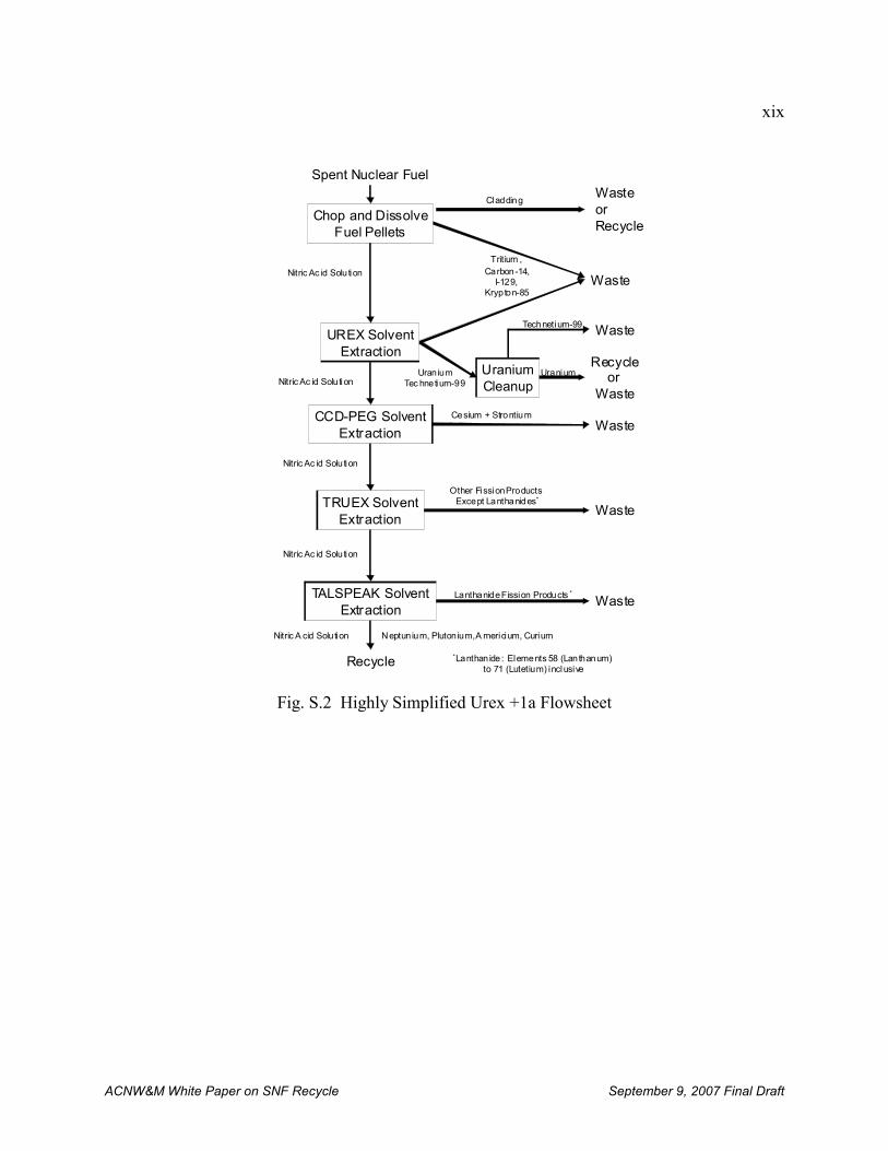
The DOE proposes using a reprocessing flowsheet called UREX (Uranium Extraction) and hascurrently stated they are favoring a variant called UREX+1a although there appears to beincreased recent interest in UREX+2 and UREX+3. A simplified UREX+1a flowsheet is shownin Fig. S.2.
Planning, experimentation, and evaluation of the UREX +1a process is in an early stage ofdevelopment (as of early 2007). Some experiments with irradiated fuel have been carried out,but there have been no lab-scale demonstrations of the entire process using SNF or large-scaletesting of key equipment using non-radioactive or uranium solutions. Additionally, thedifficulties associated with combining and operating continuously and in sequence the fourdistinctly different solvent extraction separations steps summarized above one facility have notyet been addressed. Such a facility would require extensive and expensive operator training, avery complex plant, and diverse equipment types.
xix
ACNW&M White Paper on SNF Recycle September 9, 2007 Final Draft
Fig. S.2 Highly Simplified Urex +1a Flowsheet
Chop and DissolveFuel Pellets
Spent Nuclear Fuel
UREX SolventExtraction
CCD-PEG SolventExtraction
TRUEX SolventExtraction
TALSPEAK SolventExtraction
UraniumCleanup
WasteorRecycle
Recycleor
Waste
Waste
Waste
Waste
Waste
Recycle
Cladding
Tritium , Carbon-14,
I-129, Krypton-85
Uran iumTec hnetium-99
WasteTechnetium-99
Uranium
Cesium + Strontium
Other Fission Products Except Lanthanides*
Lanthanide Fission Products *
*Lanthan ide: Elements 58 (Lanthanum) to 71 (Lutetium) inclusive
Nitric Ac id Solu tion
Neptun ium, Pluton ium, A mericium, Curium
Nitric Ac id Solution
Nitric A cid Solution
Nitric Ac id Solu tion
Nitric Ac id Solu tion
xx
ACNW&M White Paper on SNF Recycle September 9, 2007 Final Draft
In addition to the major wastes produced by the Purex flowsheet (see earlier discussion), theUREX+1a flowsheet yields the following additional wastes:
• Technetium-99 recovered from the uranium product stream that is planned to becombined with the cladding waste and dissolver solids. This mixture will be compactedor melted to form an ingot. The disposition of this waste is uncertain.
• A Cs/Sr mixture that is to be made into an aluminosilicate waste form and stored in anengineered surface facility for the time required for it to decay to Class C levels (about300 years) at which time the storage facility would be closed as a disposal facility withthe Cs/Sr remaining in place.
Some consideration is being given to building a High-Temperature Gas-Cooled Reactor (HTGR)in the U.S. HTGR fuels are distinctly different from other reactor fuels. In particular, the fuel ismade mostly of graphite, and is in one of two geometric configurations: a spherical (pebble)form and a prismatic form. Reprocessing of such fuels would be similar to reprocessing LWRfuels with one important difference: a substantial quantity of graphite must be removed byburning or crushing and sieving before the fuel matrix is dissolved in nitric acid.
In the current DOE plan pyroprocessing would be adapted to reprocessing the actinide productfrom UREX +1a after it had been refabricated into metallic or perhaps nitride fuel and irradiatedin transmutation reactor. Pyroprocessing, which involves the use of molten salts, molten metals,and electrochemical cells to separate SNF into its constituent parts, is inherently a batch process. After repeated batch processes the molten salt used in the process accumulates impurities andmust be discarded.
Advanced Fuel Fabrication and Refabrication
Current preparation of conventional pelletized reactor fuels for LWRs and fast reactors requiresgrinding the pellets to achieve specified size and shape. This process produces finely dividedfuel particles that must be recovered and recycled. A “dust-free” sol-gel microspherepelletization process has been developed for fabrication of (U,Pu)O2, (U,Pu)C and (U,Pu)N fuelpellets containing around 15% plutonium.
REGULATION AND LICENSING OF FUEL RECYCLE FACILITIES
Under current regulations, various parts of a recycle facility would have to meet therequirements of a number of regulations. The reprocessing facility per se would be licensedunder 10 CFR Part 50. Refabrication, plutonium conversion, and recovered uranium,transuranic, and Cs/Sr material storage facilities would be licensed under 10 CFR Part 70 (andalso 10 CFR Part 30 for the Cs/Sr). The uranium conversion facility would be licensed under 10CFR Part 40. The requirements of 10 CFR Part 73 (physical protection) and 10 CFR Part 74(material control and accountability) apply to all facilities.
The primary licensing regulation (10 CFR Part 50) has evolved to be focused on licensingLWRs. It would need to be modified or exemptions to many of its requirements would beneeded to be granted to accommodate the technical differences between licensing light-waterreactors and recycle facilities.
In 2007 the Commission directed the NRC staff to begin developing the regulatory framework tolicense SNF recycle facilities using an option based on 10 CFR Part 70 by preparing:
xxi
ACNW&M White Paper on SNF Recycle September 9, 2007 Final Draft
• A technical basis documentation to support rulemaking for 10 CFR Part 70 with revisionsto 10 CFR Part 50 as appropriate to eliminate its applicability to licensing a SNFreprocessing plant, and
• A gap analysis for all NRC regulations (10 CFR Chapter I) to identify changes inregulatory requirements that would be necessary to license a reprocessing facility.
Title 10 CFR Part 70 has been used to license fuel fabrication facilities and is currently the basisfor reviewing the license application for the Mixed-Oxide Fuel Fabrication Plant.
ISSUES ASSOCIATED WITH LICENSING AND REGULATING FUEL RECYCLEFACILITIES
There are a number of licensing or regulatory issues that warrant consideration before receipt ofa license application. The following sections identify these issues and provides insight into howthey might be addressed.
Development of licensing regulation(s) for recycle facilities
Implementation of SNF recycle could involve having to review license applications for facilitiesthat are novel in the context of the current once-through fuel cycle, including facilities forreprocessing fuels from LWRs and later for other advanced reactors, refabrication of fuels torecycle transuranic or fission product elements, or for some new reactor designs (e.g., graphite-moderated reactors), disposal of new types of wastes such as cladding and transuranic (GTCC)waste, and extended interim storage of intermediate-lived radionuclides (Cs/Sr), followed by insitu disposal.
There are important aspects of 10 CFR Part 70 and potential modifications thereto that will needto be considered for it to be an efficient and effective regulation for licensing SNF recyclefacilities, such as:
• Use of an Integrated Safety Analysis (ISA): 10 CFR Part 70 calls for the use of an ISA toevaluate the in-plant hazards and their interrelationship in a facility processing nuclearmaterials. The Committee and the ACRS have previously recommended that aregulation based on probabilistic risk assessment (PRA) is preferable to one based onISA because the latter has significant limitations regarding its treatment of dependentfailures, human reliability, treatment of uncertainties, and aggregation of eventsequences.
• Best estimate vs conservative: A companion issue to that of ISA vs. PRA approaches iswhether analyses should be based on data and models that represent the best estimate ofwhat might really occur with an associated uncertainty analysis to explore the effects ofincorrect data or models, or should be based on demonstrably conservative data andmodels. The Committee has letters on record pointing out problems with using thisapproach with some of the most important being that using very conservativeassumptions can mask risk-significant items, and that most conservative analyses are notaccompanied by a robust uncertainty analysis.
• One-Step Construction and Operating License (COL): 10 CFR Part 70 allows for a one-step licensing process which means that the design and process details necessary toreview the license application for a recycle facility would not available until relatively
xxii
2 NRC Commission defined risk-informed regulation in their white paper, "Risk-Informed and Performance-BasedRegulation" as “...a philosophy whereby risk insights are considered together with other factors to establishrequirements that better focus licensee and regulatory attention on design and operational issues commensurate withtheir importance to public health and safety.”
ACNW&M White Paper on SNF Recycle September 9, 2007 Final Draft
late in the licensing process. SNF recycle facilities have the potential to involveequipment, chemicals, and processes that are unfamiliar to NRC staff and that could leadto multiple requests for additional information from licensees and/or extensive pre-licensing interactions between NRC staff and the licensee to identify and resolvepotential licensing issues.
• Accommodating the Potential Future Diversity of 10 CFR Part 70 License Applications:10 CFR Part 70 is also used to license many nuclear material processing facilities otherthan those for fuel recycle. Such facilities are typically much smaller, less costly, andless complex than anticipated SNF recycle facilities to the point that imposingrequirements appropriate for recycle facilities could be unduly burdensome to someapplicants.
• Risk-informed, Performance-Based2: A risk-informed regulatory approach is one inwhich risk provides an important insight for licensing a facility but where otherconsiderations such as cost, environmental impacts, etc. can be balanced against therequired extent of risk reduction. Risk-informed regulations and licensing approaches fora wide range of situations and the opportunities for focusing scarce resources on themost-risk significant items in very complex facilities would indicate its appropriatenessin this instance. It is also prudent for regulations for licensing fuel recycle facilities toinclude provisions that allow the regulator to make exceptions on a case-by-case basis.
A corollary factor to a regulation being risk-informed is that it is performance-based. That is, the criteria for granting a license are expressed in terms of the requirements theapplicant must meet but not the means by which the applicant meets the requirement. For example, a regulation that requires that a dose limit be met is performance based butone that requires use of a specific technology is not.
• Programmatic Specificity of Changes to 10 CFR Part 70: Discussions concerningregulation of recycle facilities has been focused on DOE’s GNEP and the facilitiescurrently being proposed by DOE. The scope, functional requirements, size, and timingof these facilities is still evolving and likely to change in unknowable ways whichsuggests a more generic focus might be in order.
Impacts of SNF Recycle on Related Regulations
In addition to the need to establish the approach(es) to be used for the primary licensingregulations for fuel recycle facilities, it will be necessary to address issues that SNF recyclemight raise concerning other regulations such as:
• Classification of the wastes is an important determinant of how they must be treated,stored, transported, and disposed of. Specific issues regarding waste classificationinclude:- Whether the Cs/Sr waste will require a waste determination and DOE decision
that it is “wastes incidental to reprocessing” (WIR) so that it would not requiredisposal in a deep geologic repository and criteria for reviewing a wastedetermination for this material.
- The stable end point of cesium decay is stable isotopes of barium which means
xxiii
ACNW&M White Paper on SNF Recycle September 9, 2007 Final Draft
that the Cs/Sr waste may be a mixed waste.- Uranium, 85Kr, and 135Cs could become wastes destined for near-surface disposal
but they are not listed in the waste classification tables in 10 CFR Part 61.
• Determination of what constitutes an acceptable waste form and disposal technology forwastes such as cladding waste, Cs/Sr, miscellaneous wastes containing greater than 100nCi/g TRU (e.g., equipment and analytical wastes, protective equipment, HEPA filters),and wastes containing 99Tc, 129I, and 14C, is necessary to define how the waste must betreated. Waste form and disposal requirements also have a significant impact on theselection of recovery processes for some species such as those in gaseous effluents wheretechnology selection remains open and release limits remain to be developed.
• Use of the any of the UREX flowsheets for recycle would change the characteristics(e.g., volumes, forms, decay heat, penetrating radiation, and radionuclide concentrations)of the wastes going to the repository. As a consequence of the foregoing, aspects ofexisting regulations and guidance concerning repository licensing that are driven by thewaste characteristics (e.g., dominant contributors to repository risk, degradation rates ofthe spent fuel cladding and matrix, effects of penetrating radiation and decay heat onrepository chemistry and water flow) may change substantially and new risk-significantlicensing issues are likely to arise.
• The concentration of additional radionuclides present in recovered uranium as comparedto unirradiated uranium in certain portions of enrichment equipment and wastes, and thepenetrating radiation from 232U in the recovered uranium will have to be taken intoaccount when licensing facilities for handling recycled uranium.
• Managing Cs/Sr waste by 300-year storage followed by closure of the facility as adisposal site raises issues such as whether: - The Cs/Sr waste classified when it is produced or after the monitored interim
storage period,- A near-surface facility containing radionuclides emitting considerable amounts of
heat and penetrating radiation can be reliably designed, built, and maintained foras long as 300 years, and
- Such a long-term storage facility would be suitable for conversion to a permanentdisposal facility at that time and the technology to be used in such a conversion.
• Construction and operation of a fuel reprocessing plant before actinide burner reactorsare available would result in the need to store significant quantities of transuranicelements raising issues such as the acceptable form and technology for storing suchmaterials product and how best to safeguard it.
• A fundamental feature of DOE’s UREX flowsheets approach is that plutonium is nevercompletely separated from other more radioactive radionuclides. This raises issuesconcerning how to factor the increased radiation and difficulty in separating theplutonium into the safeguards and security paradigms that will be used in the recyclefacilities, if at all.
• An important goal in licensing SNF recycle is to include design and operatingrequirements to minimize historical problems in decommissioning the facilities at the endof their operating life. Issues arising in this regard are obtaining sufficient lessonslearned to provide a basis for decommissioning requirements to be included in
xxiv
ACNW&M White Paper on SNF Recycle September 9, 2007 Final Draft
regulations concerning SNF recycle facilities and how to balance these requirementsagainst the licensee’s freedom to build the plant to efficiently and economicallyaccomplish the principal plant mission. A separate Committee white paper is beingprepared on this issue.
• The differences among IAEA, NRC and DOE on the requirements for the permissiblesignificant (SIGMA) Pu inventory differences (ID) with regard to the Sigma ID, and thefrequency of both long-term shutdown inventory and interim frequency requirementscould be important to recycle facility operation and deserves further attention.
Other Regulatory Issues Arising from SNF Recycle
The following summarize issues that could arise from implementation of SNF recycle that do notdirectly impact NRC regulations.
• The UREX flowsheets involve at least four inter-connected processes operating in series. Each of these processes is as complex as the traditional PUREX process. This raises theissue of how to overcome the difficulty and resource requirements entailed in developingthe technical capability (expertise, analytical tools) to evaluate whether such a complexsystem can be safely operated which involves predicting the behavior of myriad pieces ofequipment and the piping connecting them under normal and accident conditions.
• Recycle facilities that are capable of meeting DOE goals will involve many processesand pieces of equipment that have never been used at a commercial scale or in a licensedfacilities. When licensing facilities the NRC normally performs confirmatory researchto validate key data and assumptions made by a licensee. In the case of recycle facilities,such research would require highly specialized facilities (e.g., hot cells) and equipmentthat is available only in a limited number of places, none of which are part of the currentNRC community. The lack of NRC infrastructure relevant to SNF recycle raises theissue of how the NRC will perform confirmatory research.
• It will be necessary to create and grade licensing examinations for fuel recycle facilityoperators at several levels of competence and responsibility. It will be challenging tofind people qualified to prepare and administer proficiency examinations.
• A number of time-consuming activities need to be completed by regulators beforeanticipated receipt of a license application for SNF recycle facilities, including creatingthe licensing regulation for recycle facilities, modifying supporting regulations, preparingguidance documents underpinning the foregoing, establishing release limits for volatileradionuclides such as 3H and 14C, and reconsidering of the waste classification anddisposal technology system. Establishing release limits for volatile radionuclides couldbe particularly lengthy because of the likely need to perform engineering design, cost,and risk studies as a basis for the limits.
The DOE also has to complete a number of time-consuming activities before it couldsubmit a license application for a recycle facility having the full capabilities presentlyenvisioned by DOE (i.e., using the UREX+1a flowsheet or similar). These activitiesinclude completing the development and testing of a complex four-step reprocessingflowsheet, testing equipment to implement the flowsheet, developing waste treatmentprocesses and disposal facilities for a number of novel waste streams, completing ageneric environmental impact statement for the recycle program, designing the facility,
xxv
ACNW&M White Paper on SNF Recycle September 9, 2007 Final Draft
and preparing the license application and other regulatory documents.
The time required to accomplish both the regulatory and DOE activities is likely to be atleast several years but this estimate has a substantial degree of uncertainty. However, theDOE could decide to initially deploy SNF recycle facilities that do not have the fullcapabilities presently envisioned by DOE and then add additional modules over time toachieve the full capabilities. Such an approach is significantly less complex thanimplementing all the envisioned capabilities at the outset and represents only a modestextension of existing technology. As a consequence, the time required to develop andsubmit a license application could be significantly reduced as compared to that for a fullycapable facility but the time required to undertake the required regulatory developmentwould not be significantly reduced.
• In the 1970s when nuclear fuel recycle was being aggressively pursued efforts wereundertaken to by the EPA to develop standards for radionuclide releases from recyclefacilities with the results being codified in 40 CFR Part 190. From the perspective ofdecades of hindsight, the existing standard raises a number of issues as follows:- The factors by which 85Kr and 129I must be reduced are approximately 7-fold and
200-fold, respectively. The evaluation which led to these factors was based oneffluent control technologies that were under development such development wasnever completed. Thus, meeting the standard with available technologies may notbe not feasible.
- Background information accompanying the standard indicated that studiesconcerning limits on releases of 14C and 3H were underway. These studies remainto be completed and, thus, the standard may be incomplete.
- The cost-benefit approach used in the analyses involved calculating the collectivedose by integrating very small doses over very large populations and distances,and comparing them to then-common metrics such as a limit of $1000/man-remto determine whether additional effluent controls were justified. As has beenobserved in Committee letters and by the ICRP, such a comparison isquestionable.
- The scope of 40 CFR Part 190 does not include fabrication of fuels enriched withplutonium or actinides other than uranium.
In summary, the EPA standard on which effluent release limits are based may imposerequirements that are infeasible in the near-term, may be incomplete, and is based onanalysis techniques that have become questionable over the years. This is a very fragile(if not inadequate) foundation for the NRC to develop implementing regulations andbegin licensing a fuel recycle facility.
• Implementing fuel recycle will require a substantial number of staff knowledgeable aboutthe technical and regulatory aspects of fuel recycle facility design and operation. Thedesign and operation of the fuel reprocessing and recycle fuel fabrication facilities areparticularly challenging because staff trained as nuclear chemical operators and engineersis required and few exist because there has been very limited demand for decades. Thissame expertise, especially that of nuclear chemical engineers, will be in demand byorganizations performing fuel recycle R&D, designing and operating recycle facilities,and regulating recycle facilities thus exacerbating the demand .
• The GNEP’s goals include having once-through and recycle facilities in the U.S.providing services (fuel supply, fuel take-back) as a primary component. Withsubstantial amounts of U.S. fuel going to many other countries and being returned to theU.S., a more focused relationship between the NRC and regulators in other countries
xxvi
ACNW&M White Paper on SNF Recycle September 9, 2007 Final Draft
might be desirable or necessary to ensure that U.S. fuels are acceptable internationallyand that fuel irradiated in another country has an acceptable pedigree for its return.
• The DOE regulates most of its activities under its own authority while the NRC regulateslicensees doing civilian and commercial nuclear activities. In the case of the projectedfuel recycle facilities there is the potential for DOE regulating some facilities thatinterface with other NRC-regulated facilities (e.g., a fuel refabrication plant andassociated waste management facilities such as at MFFP). This could pose challengesconcerning compatibility and consistency of regulatory requirements, especially as itconcerns material that moves between facilities, and how it is moved.
• The development and design of recycle facilities provides an excellent opportunity toeducate and train NRC staff for licensing subsequent facilities and to obtain insightsuseful in developing or modifying NRC regulations to license these facilities. Ofparticular note is a stepwise end-to-end demonstration of the UREX+1a flowsheet nowunderway at ORNL beginning with SNF receipt and ending with refabrication of fuelscontaining TRU elements and use of waste materials (e.g., Tc, Cs/Sr) to developtreatment processes.
RESEARCH NEEDS
Implementation of SNF recycle in the U.S. as presently envisioned by DOE will requireinformation that will presumably result from DOE’s ongoing research and development programor international experience. However, to fulfill its role in developing regulations and laterreviewing a license application for SNF recycle facilities, the NRC staff must be able toindependently assess the safety of the facilities. Such an assessment requires sufficientunderstanding of key technical aspects of the processes and materials in the plant. In the courseof becoming preparing the white paper the following research needs that are likely to beimportant to the NRC’s regulatory role were noted:
• Knowledge of the split of each chemical species in each process step in the plant (theseparation factors), especially concerning tritium, iodine, technetium, neptunium, andradioactive material associated with the cladding.
• Developing a model that simulates the interconnected equipment in a facility flowsheetusing the separation factors to determine the radionuclide concentrations and inventory. Such models need to accommodate complexation, colloids, internal recycle streams, andimportant conditions in bulk fluids (e.g., temperature, acidity, radiolysis).
• Understanding stability of organic extractants, solvents, and ion exchange materials andthe safety implications of degradation products.
• Understanding and documenting the technical status and cost of effluent controltechnologies and to develop a methodology for performing the cost-benefit analysis.
• Understanding the performance of potential waste forms for krypton, iodine, carbon,technetium, and Cs/Sr in likely storage and disposal environments.
• A better understanding of the strengths, limitations, and historical performance of long-term institutional controls and facility degradation rates in the context of reviewing alicense application for 300 years of near-surface storage of Cs/Sr is desirable to provide abasis for these judgements.
1
ACNW&M White Paper on SNF Recycle September 9, 2007 Final Draft
I. INTRODUCTION
A. Background and context
The SNF from existing and future nuclear power reactors in the U.S. poses challenges asfollows:
• Obtaining adequate disposal capacity for SNF and HLW: The U.S. currently has 104operating commercial nuclear power reactors [NEI, 2007] that produce about 2100tonnes of spent nuclear fuel each year [Kouts, 2007]. DOE estimates that theCongressionally mandated capacity limit of 70,000 tonnes of heavy metal equivalentimposed on the proposed Yucca Mountain (YM) repository will be committed toaccumulated spent commercial fuel and other DOE wastes by about 2010 [DOE, 2006]leading to the need for additional disposal capacity beyond this time. It has beenestimated [Kessler, 2006] that if the currently planned approach to emplacing SNF inYucca Mountain were maintained the physical capacity of the site is 2.0 to 3.5 times the70,000 tonne legislative limit. Thus, expansion of Yucca Mountain to its physical limitscould accommodate spent fuel from an additional 33 to 83 years of operating existingnuclear power plants but proportionately less if there is additional SNF from reactorsundergoing license extensions, new reactors similar to those presently deployed, and newtypes of advanced reactors. The characteristic of SNF that limits how much can beplaced in a unit area of the repository is limited by its decay heat which is dominated by90Sr and 137Cs for the first several decades and by certain transuranic actinide isotopesbeyond this time with plutonium and 241Am being the dominant contributors. Thevolume of the SNF does not drive the amount of repository area required to dispose ofSNF although the volume of SNF does affect the number of storage and shipping casksthat must be handled and transported.
• Increase Utilization of Available Energy Resources: The SNF from commercial powerreactors contains two significant sources of fissile material that could be recovered andreused. The first is the 235U remaining after the fuel that was initially contained (up to5% of this isotope) has been depleted. The 235U concentration in SNF is typically severaltenths of a percent (about the same as natural uranium) and it could be re-enriched toyield some additional uranium for fuel. The second significant source of fissile materialin SNF is the transuranic elements created by neutron irradiation of 235,238U withplutonium being the most important because it constitutes at least 1% of typical SNF andabout two-thirds of the plutonium is fissionable in the thermal neutron spectrum inLWRs.
• Avoiding the Increased Proliferation Risk from a Pure Plutonium Stream: The plutoniumcontained in SNF has been recovered and reused in many countries. However, theprocesses that have been used to recover it generate the product as a stream of pureplutonium than can be handled with little or no radiation shielding and, as a consequence,pose a proliferation risk. This proliferation risk is an undesirable aspect of existingrecovery processes that has impeded the reuse of plutonium
• Reduce Disposal Risks from Key Radionuclides: SNF contains many radionuclides thatcould be dissolved from failed waste canisters in a closed repository, migrate to thebiosphere, and constitute a risk to the public. However, only a few radionuclides havethe necessary combination of longevity and mobility so as to be important contributors torisk [EPRI, 2003], most notably 99Tc, 129I, and 237Np and its decay products. Theneptunium in SNF is produced directly by neutron irradiation of 235U as well as from the
2
3 For the purposes of this document, “recycle” involves (a) separation of the constituents of spent nuclear fuel, (b)refabrication of fresh fuels containing plutonium, minor actinides, and possibly some fission products, c)management of solid, liquid, and gaseous wastes, and (d) storage of spent fuel and wastes.
ACNW&M White Paper on SNF Recycle September 9, 2007 Final Draft
decay of 241Pu and 241Am in the SNF that is produced by neutron irradiation of 238U.
The DOE has been supporting programs to recycle SNF for a number of years. Specifically,DOE is proposing to reprocess SNF (separate it into its constituent components) with LWR fuelbeing the primary feedstock for the foreseeable future; reuse the recovered uranium; reuse theplutonium by making it into new reactor fuel (refabrication); destroy actinides that dominaterepository risk by refabricating them into fuel or targets; irradiate the actinides in a nuclearreactor; and incorporate radionuclides that cannot be readily destroyed by irradiation into wasteforms better than SNF. To address proliferation concerns, DOE proposes to reprocess the SNFusing new approaches that do not produce a separated plutonium stream.
The DOE’s current program for implementing its proposed approaches is the Global NuclearEnergy Partnership (GNEP). This program contemplates building three facilities: an integratednuclear fuel recycle facility3, an advanced reactor for irradiating Np, Pu, Am, and Cm, and aadvanced fuel cycle research facility to develop the technology needed by GNEP.
In the conference report associated with the FY 2006 Energy and Water Appropriations bill [Congress, 2005] Congress directed DOE to select a site for the integrated nuclear fuel recyclefacility by FY 2007 and to initiate construction of one or more such facilities by FY 2010. DOEsubsequently submitted a program plan [DOE, 2006a] and a strategic plan [GNEP, 2006] providing details of their path forward and has continued to refine these plans.
Fuel recycle has the potential to require changes in the NRC’s existing regulatory frameworkand expertise which are now structured to license light-water reactors and their associated once-through fuel cycle facilities including direct disposal of spent fuel. In recognition of thispotential the Commission directed [NRC, 2006 a, b] that the Advisory Committee on NuclearWaste and Materials (the Committee) become knowledgeable concerning developments in fuelrecycle and help in defining the issues most important to the NRC concerning fuel recyclefacilities.
In FY 2006 the Committee received initial briefings by Committee consultants, NRC staff, andDOE staff on fuel recycle. Based on this input the Committee decided that the most efficientway to meet the potential needs of the Commission was to prepare a white paper on fuel recycle. A group of expert consultants was chartered to do so. This paper is the result of the efforts ofthose consultants.
B. Goal and Purposes
The primary goal of this paper is to summarize the technical, regulatory, and legal history, status,and issues concerning SNF recycle for two purposes:
1. To provide the basis for a Committee letter to the Commission providing theCommittee’s initial insights on important regulatory issues that DOE’s SNF recycleinitiative would raise and provide recommendations on what the NRC should do toaddress them and when.
2. Additionally, noting that decades have elapsed since the NRC attempted to license fuelrecycle facilities, the second purpose of the paper is “knowledge management”: capturingthe expertise of some experts (those preparing and reviewing the paper) concerning the
3
ACNW&M White Paper on SNF Recycle September 9, 2007 Final Draft
history of SNF recycle and implications for current SNF recycle programs for use by allelements of the NRC.
This paper is intended to be generic and not focused exclusively on the current U.S. programdirected at implementing SNF recycle: GNEP. However, if SNF facilities regulated by the NRCare built in the U.S. they will reflect a focus on the policies, goals, and priorities of the U.S. SNFrecycle program as modified in the future. As a consequence, important aspects of this papernecessarily reflect the goals and priorities of the current GNEP program and its technologyselections because the future is unknowable. The impact of this focus is mitigated by the factthat the current GNEP program is significantly more ambitious than those in most othercountries (France is an exception) because it proposes to separate SNF into a larger array ofproducts and wastes than those produced or currently planned in other countries. If some ofthese separations are not performed, then specific portions of this paper may be academic, but itis believed that the major messages will be robust into the future.
In addition to understanding the purposes of this paper, it is equally important for the reader tounderstand that the paper is not intended to:
• Address the implications of advanced reactors: This paper does not address theimplications of potential new power production and/or transmutation reactors (e.g., fast-neutron-spectrum reactors for fissioning TRU elements) or devices (e.g., accelerators fortransmutation) to the NRC’s regulations and infrastructure. This is the purview of theNRC’s Advisory Committee on Reactor Safety (ACRS). The paper does briefly describethe fuels that might be used in such reactors because this is the potential feed for areprocessing plant.
• Provide detailed recycle technology descriptions and characterization: This paper doesnot contain detailed descriptions of the SNF recycle science or technology, or thecharacteristics of internal plant streams for multiple reasons:- Such descriptions are not needed to accomplish the paper’s goal as stated earlier.- Reliable details concerning the science and technology underlying GNEP recycle
proposals is not available because the processes are still under development.- Where available, detailed descriptions of technology and internal plants streams
are proprietary, sensitive for security reasons, or both, which would precludeissuing this paper as a public document.
Detailed descriptions of historical science and technology have been included byreference.
• Provide details on pyroprocessing: If SNF recycle is to proceed, the first and largestoperation will necessarily be to reprocess LWR fuel. Aqueous processes such as thosecurrently in use internationally or advanced versions being developed in the U.S. andelsewhere are very likely to be used on LWR fuels because they were developed for thispurpose. As a consequence, aqueous processes are the focus of this paper. Pyroprocesses (using molten metals and salts, and electrochemical cells to accomplishSNF separation) were conceived to reprocess metal fuels and may have application tooxides and to advanced fuels such as nitrides and carbides. A brief description of suchprocesses is included in this paper.
• Focus on fuel fabrication and refabrication: Fabrication of new reactor fuels from theplutonium resulting from LWR fuel reprocessing and licensing of facilities forfabricating them is established practice with U/Pu oxide fuels being used in many
4
ACNW&M White Paper on SNF Recycle September 9, 2007 Final Draft
countries and a U.S. facility is in the licensing process as this paper is written. Whileinclusion of a mixture of transuranic actinides (Np, Pu, Am, Cm) does present someadditional technical challenges for fabrication (e.g., much higher emission of radiationand heat), a refabrication facility for this purpose would not raise the variety of majorconceptual and practical issues that SNF reprocessing does.
• Evaluate the merits of DOE’s technical or programmatic approach: As stated previously,the purposes of this paper are to support preparation of a Committee letter on regulatoryissues that would be raised by SNF recycle and what the NRC should do to address theissues, and to aid in capturing knowledge that is rapidly being lost because it has not beenneeded in the U.S. for decades. Evaluation of DOE’s program is the purview ofappropriate elements of the Executive and Legislative branches, independent reviewgroups, and other interested stakeholders.
• Contain conclusions and recommendations: Conclusions and recommendations regardingthe implications of SNF recycle to the NRC will be contained in a Committee letter.
C. Scope
In attempting to meet the goal and purposes stated above, this paper addresses the followingtopics:
• A historical overview of fuel recycle including recycle programs, reprocessingtechnology and facilities, and fuel refabrication technology and facilities.
• A historical overview of the siting, design, operation and material accountability of fuelrecycle facilities that describes how recycle technologies were integrated into anoperating facility designed to meet then-applicable (the late 1970s) regulations and someneeded improvements that were evident even at that time.
• An overview of current recycle activities including ongoing U.S. and international fuelrecycle programs, a brief discussion of advanced reactors and the spent fuel they wouldgenerate (which is the feedstock for recycle facilities), and discussion of the advancedfuel recycle processes that are being developed.
• A scoping calculation of the nature and characteristics of wastes that might result fromGNEP’s currently favored SNF reprocessing flowsheet.
• Discussion of regulation and licensing of fuel recycle facilities, including:- Experience with licensing two such facilities in the 1970s and earlier;- Discussion of regulations that might be used to license new fuel recycle facilities
including existing and potential new regulations;- Topics related to licensing such as environmental protection requirements
(primarily effluent controls) and other environmental impacts; and- Recent proposals by the NRC staff on how fuel recycle facilities might be
licensed and Commission direction related thereto.
• A discussion of issues relevant to licensing recycle facilities, including the licensingregulation per se, potential impacts on other NRC regulations, implications to NRCexpertise and infrastructure, and timing.
D. Information Sources
5
ACNW&M White Paper on SNF Recycle September 9, 2007 Final Draft
In addition to the many publicly available documents reviewed to prepare this white paper, otherimportant sources of information are as follows:
• Presentation by R. G. Wymer to the 171st ACNW Full Committee, June 6, 2006, Subject:Commercial Spent Nuclear Fuel Reprocessing
• Presentation by DOE Representatives to 172nd ACNW Full Committee, July 20, 2006Subject: Advanced Fuel Cycle Initiative (AFCI)
• L. Tavlarides trip to ANL for discussions on AMUSE code calculations, October 6, 2006
• ACNW Members trip to Hanford to tour reprocessing-like facilities, Oct 17 -18, 2006
• J. Flack and L. Tavlarides trip to Argon National Laboratory, October 24-25, 2006
• Presentations by R. G. Wymer, and L. Tavlarides to 174th ACNW Full Committee,November 15, 2006, Subject: White Paper on Potential Advanced Fuel Cycles
• Presentations by NRC/NMSS staff to 175th ACNW Full Committee, December 13, 2006Subject: Conceptual Licensing Process for Global Nuclear Energy Partnership (GNEP)Facilities
• Presentation by GAO representative to ACNW, April 11, 2007, Subject: Scope andMethodology of the Government Accountability Office (GAO)’s Ongoing Review of theGlobal Nuclear Energy Partnership (GNEP) Effort.
• ACNW Member A. G. Croff attendance at briefing by DOE on GNEP wastemanagement strategic plan in April, 2007 NAS Nuclear and Radiations Studies Boardmeeting
• ACNW Member A. G. Croff attendance at May 2007 NWTRB meeting to hear JimLaidler presentation on GNEP waste streams
• Presentation by AREVA representative to 179th Committee meeting, May 16, 2007,Subject: AREVA Spent Nuclear Fuel Recycle Facilities
• Presentation by Energy solutions to 181st Committee meeting, July 19, 2007, Subject:BNFL’s Reprocessing Technology
• Round table discussion with 181st Committee meeting and internal and externalstakeholders, July 19, 2007, Subject: Committee White Paper on Spent Nuclear FuelRecycle Facilities
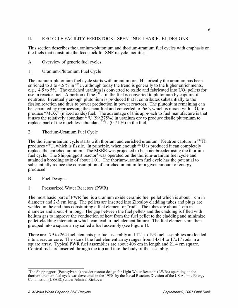
6
4The Shippingport (Pennsylvania) breeder reactor design for Light Water Reactors (LWRs) operating on thethorium-uranium fuel cycle was developed in the 1950s by the Naval Reactors Division of the US Atomic EnergyCommission (USAEC) under Admiral Rickover.
ACNW&M White Paper on SNF Recycle September 9, 2007 Final Draft
II. RECYCLE FACILITY FEEDSTOCK: SPENT NUCLEAR FUEL DESIGNS
This section describes the uranium-plutonium and thorium-uranium fuel cycles with emphasis onthe fuels that constitute the feedstock for SNF recycle facilities.
A. Overview of generic fuel cycles
1. Uranium-Plutonium Fuel Cycle
The uranium-plutonium fuel cycle starts with uranium ore. Historically the uranium has beenenriched to 3 to 4.5 % in 235U, although today the trend is generally to the higher enrichments,e.g., 4.5 to 5%. The enriched uranium is converted to oxide and fabricated into UO2 pellets foruse in reactor fuel. A portion of the 238U in the fuel is converted to plutonium by capture ofneutrons. Eventually enough plutonium is produced that it contributes substantially to thefission reaction and thus to power production in power reactors. The plutonium remaining canbe separated by reprocessing the spent fuel and converted to PuO2 which is mixed with UO2 toproduce “MOX” (mixed oxide) fuel. The advantage of this approach to fuel manufacture is thatit uses the relatively abundant 238U (99.275%) in uranium ore to produce fissile plutonium toreplace part of the much less abundant 235U (0.71 %) in the fuel.
2. Thorium-Uranium Fuel Cycle
The thorium-uranium cycle starts with thorium and enriched uranium. Neutron capture in 232Th produces 233U, which is fissile. In principle, when enough 233U is produced it can completelyreplace the enriched uranium. The MSBR was projected to be a net breeder using the thoriumfuel cycle. The Shippingport reactor4 was operated on the thorium-uranium fuel cycle andattained a breeding ratio of about 1.01. The thorium-uranium fuel cycle has the potential tosubstantially reduce the consumption of enriched uranium for a given amount of energyproduced.
B. Fuel Designs
1. Pressurized Water Reactors (PWR)
The most basic part of PWR fuel is a uranium oxide ceramic fuel pellet which is about 1 cm indiameter and 2-3 cm long. The pellets are inserted into Zircaloy cladding tubes and plugs arewelded in the end thus constituting a fuel element or “rod”. The tubes are about 1 cm indiameter and about 4 m long. The gap between the fuel pellets and the cladding is filled withhelium gas to improve the conduction of heat from the fuel pellet to the cladding and minimizepellet-cladding interaction which can lead to fuel element failure. The fuel elements are thengrouped into a square array called a fuel assembly (see Figure 1).
There are 179 to 264 fuel elements per fuel assembly and 121 to 193 fuel assemblies are loadedinto a reactor core. The size of the fuel element array ranges from 14x14 to 17x17 rods in asquare array. Typical PWR fuel assemblies are about 406 cm in length and 21.4 cm square. Control rods are inserted through the top and into the body of the assembly.
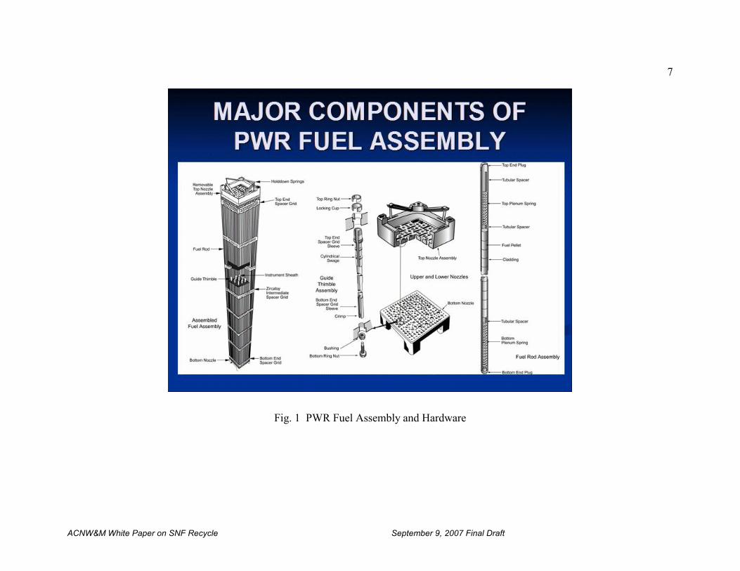
7
ACNW&M White Paper on SNF Recycle September 9, 2007 Final Draft
Fig. 1 PWR Fuel Assembly and Hardware
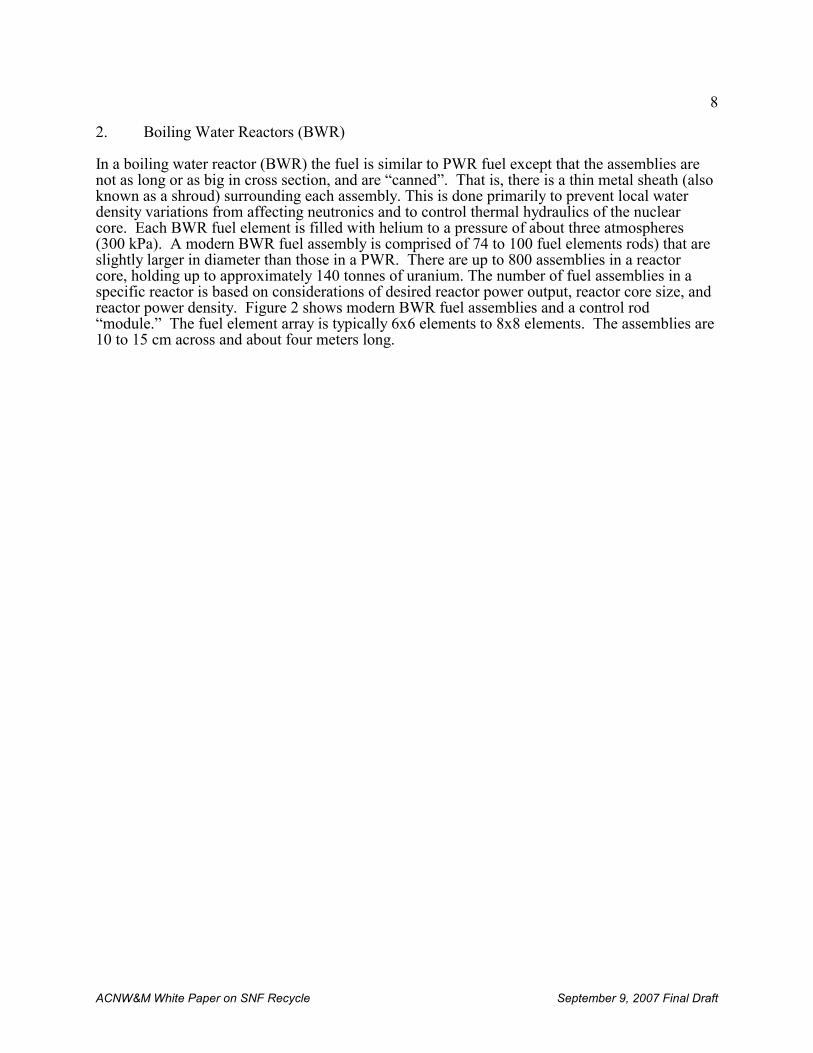
8
ACNW&M White Paper on SNF Recycle September 9, 2007 Final Draft
2. Boiling Water Reactors (BWR)
In a boiling water reactor (BWR) the fuel is similar to PWR fuel except that the assemblies arenot as long or as big in cross section, and are “canned”. That is, there is a thin metal sheath (alsoknown as a shroud) surrounding each assembly. This is done primarily to prevent local waterdensity variations from affecting neutronics and to control thermal hydraulics of the nuclearcore. Each BWR fuel element is filled with helium to a pressure of about three atmospheres(300 kPa). A modern BWR fuel assembly is comprised of 74 to 100 fuel elements rods) that areslightly larger in diameter than those in a PWR. There are up to 800 assemblies in a reactorcore, holding up to approximately 140 tonnes of uranium. The number of fuel assemblies in aspecific reactor is based on considerations of desired reactor power output, reactor core size, andreactor power density. Figure 2 shows modern BWR fuel assemblies and a control rod“module.” The fuel element array is typically 6x6 elements to 8x8 elements. The assemblies are10 to 15 cm across and about four meters long.
9
ACNW&M White Paper on SNF Recycle September 9, 2007 Final Draft
Fig. 2 BWR fuel assembly
10
5 Uranium and plutonium isotopes are both fissionable, so it is convenient to refer to the fissile content of fuel interms of “equivalent enrichment,” i.e., with fissile characteristics as though it were all enriched uranium.
6 An important exception is the fast reactor development program in India, which is based on carbide fuels.
ACNW&M White Paper on SNF Recycle September 9, 2007 Final Draft
3. Fast Reactors
Historically, the core of a fast reactor consisted of an array of canned fuel assemblies containinga hexagonal array of fuel elements. The fuel element cladding and can are both made ofstainless steel which allows these reactors to operate at higher temperatures than LWRs. Whensuch reactors were designed to produce more plutonium than they consumed, i.e., to “breed”, thecore was comprised of a central region of mixed-oxide fuel (called driver fuel) that could sustaina chain reaction. Above and below the driver fuel were elements containing pellets of depleteduranium called a blanket. Additionally, surrounding the driver assemblies in the radial directionwere fuel assemblies in which the fuel pellets were all depleted uranium. When these assembliesare placed together, the result is creation of a central cylindrical “driver” region surrounded onall sides by the blanket. The purpose of this configuration was to use neutrons that leaked fromthe driver fuel to produce plutonium in the blanket.
The fuel elements are kept apart by grid spacers or in some cases by wire wound helically alongeach element. Driver fuel elements are typically stainless steel tubes 6 or 7 mm in diameter. Inearly designs, the elements in the blanket were larger in diameter, about 1.5 cm, because theyrequire less cooling than the fuel elements. Both fuel and blanket elements may be more tightlypacked in liquid-metal- (e.g., sodium, Na/K, lead, bismuth) cooled fast reactors than in LWRsbecause the heat transfer properties of the liquid metal are so much better than those of water. This may not be the case for gas-cooled fast reactors.
In the GNEP concept the objective of future fast reactors is to fission as many of the transuranicelements as practical while still producing electricity. Thus, instead of producing about 10%more plutonium as would have been the case with breeder reactors, DOE is seeking to haveadvanced burner reactors (ABRs) consume a net 25% to 75% of the transuranic elements in freshfuel. One consequence of this is it is unlikely that there will be any blanket fuel in the ABR andit is possible some or all of the 238U in the driver fuel may be replaced by another diluentelement, e.g., Zr, that does not produce plutonium.
Fast reactor fuel may be made of several different materials. The principle materials arediscussed below.
a. Oxide
Oxide fuel is made up with pellets composed of a mixture of oxides of plutonium and uranium.In the ABR other transuranic elements may be included. The equivalent enrichments5 of the fuelrange between 15 to 35% depending on the reactor in question.
b. Carbide
Historically and up to the present time metallic and oxide fuels have been used in fast reactors.6 There is, however interest in the use of fuel composed of uranium/plutonium carbide,particularly in India. Carbide fuels have a higher thermal conductivity than oxide fuels and,where plutonium breeding is of interest, can attain breeding ratios larger than those of oxidefuels. The increase in breeding ratio is due to the fact that while there are two atoms of oxygenper atom of uranium in the oxide, there is only one atom of carbon per uranium atom in thecarbide. Light atoms such as carbon and oxygen tend to moderate fission neutrons, and since
11
ACNW&M White Paper on SNF Recycle September 9, 2007 Final Draft
there are fewer atoms per fissile atom in the carbide than in the oxide, it follows that the energydistribution of neutrons in a carbide-fueled fast reactor is shifted to higher energies than in acomparable oxide-fueled fast reactor. In addition, the density of uranium is higher.
c. U/Pu/Zr
An alloy of uranium/plutonium/zirconium (U:71 %; Pu:19 %; Zr:10 %) in stainless steelcladding has shown considerable promise as a fast reactor fuel. It has been irradiated to burnupswell over 15 atom percent (Phal, 1990) with no deleterious effects that preclude seriousconsideration of its use, although some swelling and cladding interactions have been observed atthese very high burnups.
d. Nitride
There has been interest shown in using uranium and/or plutonium nitride in fast reactors formany of the same reasons that carbide is attractive as a fuel. DOE is developing such fuels. Animportant disadvantage of nitride fuels is that they can form significant amounts of 14C byneutron capture in the 14N isotope of the nitrogen component. In order to overcome this problemit would be necessary to perform a nitrogen isotope separation to remove the bulk of the 14N.
A drawing of typical historical fast breeder reactor fuel assembly is shown in figure 3. Fueldesigns for the ABR are still evolving.
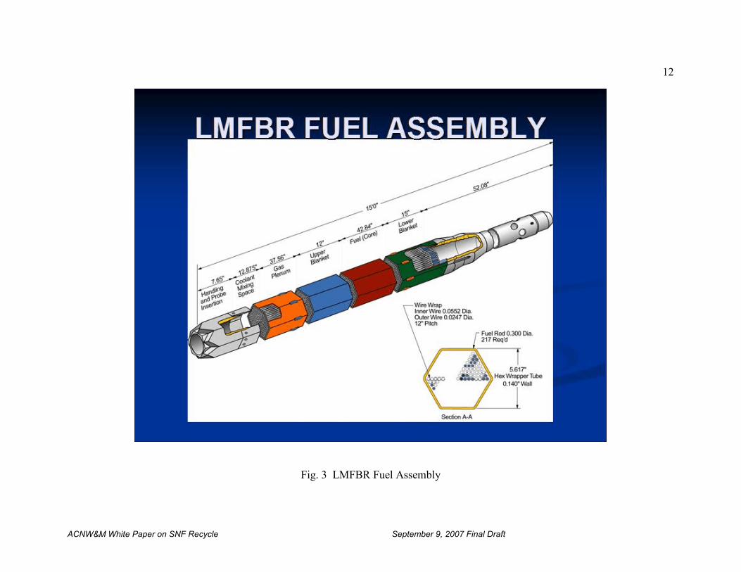
12
ACNW&M White Paper on SNF Recycle September 9, 2007 Final Draft
Fig. 3 LMFBR Fuel Assembly
13
7 South Africa has a modular pebble bed reactor under active development.
ACNW&M White Paper on SNF Recycle September 9, 2007 Final Draft
4. High-Temperature Gas-Cooled Reactors (HTGR)
There are two types of HTGR fuel assemblies: spherical (called pebbles) and prismatic blocks. The former were developed in Germany in connection with the AVR and the first GermanHTGR power plant, the THTR 300.7 Currently pebble bed fuel assemblies are being used in theexperimental reactors HTR-10 in China and in Russia. The HTTR in Japan is based on prismaticfuel forms. Prismatic fuels were developed in the U.S. by General Atomics and were usedcommercially in the 330 Mwe Fort St. Vrain reactor.
In both cases the fuel matrix is composed of compounds of uranium and thorium or plutonium inthe form of a ceramic (usually oxides, oxycarbides, or carbides). The fuel “element” in bothcases is a “triso” fuel microsphere which is typically about one millimeter in diameter. TRISOfuel typically consists of a fuel kernel containing the fuel matrix in the center, coated with fourlayers of material. The four layers are a porous graphite buffer layer whose porosity providesspace for fission gases, followed by a dense inner layer of pyrolytic carbon (PyC), followed by aceramic layer of SiC to retain fission products at elevated temperatures and to give the TRISOmicrosphere more structural integrity, followed by a dense outer layer of PyC. TRISO fuelmicrospheres are designed to not crack due to the stresses from processes (such as differentialthermal expansion or fission gas pressure) at temperatures beyond 1600°C, and therefore cancontain the fuel and fission products in the worst accident scenarios in a properly designedreactor. See Sect. III.B.3 for a detailed discussion of HTGR fuel fabrication. These fuelmicrospheres are enclosed in graphite “pebbles” or prismatic graphite blocks that act as theprimary neutron moderator.
5. Molten Salt Reactor (MSR)
The MSR is a unique reactor concept. It does not use a solid fuel. Instead, it uses a moltenfluoride salt fuel that circulates in a loop. The loop contains a heat exchanger to extract fissionenergy and a system that removes fission products, primarily lanthanides and noble gases, whosepresence would “poison” the salt (i.e., would capture neutrons) and ultimately prevent fissionfrom occurring. The fuel for the Molten Salt Reactor Experiment (MSRE) was LiF-BeF2-ZrF4-UF4 (65-30-5-0.1). A graphite core moderated the neutrons. The secondary coolant was F-Li-Be(2LiF-BeF2). The reactor operated at a peak temperature of 650°C and operated for theequivalent of about 1.5 years of full power operation.
The culmination of the Oak Ridge National Laboratory research during the 1970-76 time frameresulted in a MSR design that would use LiF-BeF2-ThF4-UF4 (72-16-12-0.4) as fuel. It was to bemoderated by graphite with a 4 year replacement schedule, to use NaF-NaBF4 as the secondarycoolant, and to have a peak operating temperature of 705°C. However, to date no commercialmolten salt reactors have been built.
14
8 The terms single-shell and double-shell refer to whether the tanks had only one wall and bottom or whether theywere, in effect, a tank within a tank. Many of the single-shell tanks have developed leaks to the sub-soil.
ACNW&M White Paper on SNF Recycle September 9, 2007 Final Draft
III. OVERVIEW OF SPENT NUCLEAR FUEL RECYCLE
A. Reprocessing Experience and Evaluations
A great deal of the technical information needed for reprocessing spent nuclear fuel and for fuelrecycle in general has been available for many years and may be found in the publicly availableliterature. The general references at the end of this paper are indicative of the amount of detailedinformation available and the very long time it has been available. Notwithstanding this wealthof literature information there is another component of knowledge that is related to operatingexperience that cannot be conveyed in any way other than operating actual fuel cycle facilities. Some information on early fuel cycle evaluations and the current or formerly operating recyclefacilities is presented in what follows.
1. U.S. Defense and Commercial Reprocessing Plants
In the post-World War II years spent fuel reprocessing to recover plutonium for use in weaponsand highly enriched uranium from naval reactor fuel was still carried out for many years in DOE(formerly the AEC) operated government facilities.
a. Reprocessing for Weapons Plutonium Recovery
Large-scale reprocessing of irradiated nuclear reactor fuel to recover plutonium for use innuclear weapons began in the United States following the second World War and continued untilthe 1980s. Reprocessing was carried out in large government–owned plants located in Richland,WA and Savannah River, SC for plutonium production. A plant was also constructed at IdahoFalls, ID to recover uranium from spent naval reactor fuels. The earliest large-scale plutoniumrecovery process was the bismuth phosphate process which was a multi-step precipitationprocess developed by G. Seaborg and co-workers in very small-scale laboratory experiments andcarried directly into large-scale production at the Hanford site in Richland, WA. It was soonreplaced with a succession of solvent extraction processes that were much simpler to operate andmore efficient. These processes and subsequent approaches used to manage them (e.g.,neutralization of acidic wastes) did, however, produce copious amounts of waste, both liquid andsolid and radioactive and non-radioactive. Millions of gallons of highly radioactive liquid waste(HLW) were stored in large “single-shell” and “double-shell”8 tanks on the Hanford andSavannah River sites. Most of this waste still resides in the tanks as sludge and caked salt,although efforts are underway to remove and vitrify it.
i. Bismuth Phosphate Process
The Bismuth Phosphate Process for extracting plutonium from irradiated uranium wasdemonstrated in a pilot plant built beside the Oak Ridge X-10 Reactor in 1944. At productionscale the process produced a large amount of highly radioactive waste that contained all of theuranium in the SNF, and the bismuth phosphate process was soon replaced by a solventextraction process. (See the following section.) The process was designed to recover plutoniumfrom aluminum-clad uranium metal fuel. The aluminum fuel cladding was removed bydissolving it in a hot solution of sodium hydroxide. After de-cladding, the uranium metal wasdissolved in nitric acid. The plutonium at this point was in the +4 oxidation state. It was thencarried from solution by a precipitate of bismuth phosphate formed by the addition of bismuth
15
9 Ferrous sulfamate was chosen because the ferrous ion reduced the plutonium to inextractable Pu (III) and thesulfamate ion reacted to destroy any nitrous acid present. Nitrous acid had a deleterious effect on the uranium-plutonium separation process.
10 It should be noted that large amounts of non-volatile salts were added in the bismuth phosphate process, resultingin a large salt residue in the waste. In modern solvent extraction plants great care is taken to eliminate as many non-volatile salts as possible.
ACNW&M White Paper on SNF Recycle September 9, 2007 Final Draft
nitrate and phosphoric acid. The supernatant liquid (containing many of the fission products)was separated from the precipitate which was then dissolved in nitric acid. An oxidant such aspotassium permanganate was added to convert the plutonium to soluble PuO2
2+ (Pu VI). Adichromate salt was added to maintain the plutonium in the +6 oxidation state. The bismuthphosphate was then re-precipitated, leaving the plutonium in solution. Then an iron salt such asferrous sulfamate9 was added and the plutonium re-precipitated again using a bismuth phosphatecarrier precipitate as before. Then lanthanum and fluoride salts were added to create a lanthanumfluoride precipitate which acted as a carrier for the Pu. Repeated precipitations and dissolutionswere used to remove as many impurities as practical from the plutonium. The precipitate wasconverted to oxide by the addition of a chemical base and subsequent calcination. Thelanthanum-plutonium oxide was then collected and plutonium was extracted from it with nitricacid to produce a purified plutonium nitrate solution10.
ii. Redox Process (Hexone)
The Redox Process was a solvent extraction process used in defense SNF reprocessing facilitiesof the 60s and 70s. It was a process wherein an acidic aqueous solution containing the dissolvedspent nuclear fuel was contacted with an essentially immiscible organic solvent (methyl isobutylketone) that preferentially removed uranium and plutonium (and, if desired, other actinides)from the aqueous phase. Many of the solvents employed early (such as Hexone) had significantdrawbacks, such as high flammability, susceptibility to chemical and radiation damage,volatility, excessive solubility in water, high viscosity, and high cost. Solvents used in earlylarge-scale reprocessing plants included methyl isobutyl ketone (Hexone) which was used at theHanford plant in Richland, WA, and β,β’-dibutoxydiethylether (Butex) which was used by theBritish. Bis-(2 ethylhexyl) phosphoric acid (HDEHP) has been used in smaller scaleapplications.
The REDOX process was developed at Hanford in the late 1940s to replace the bismuthphosphate process and was used in the site’s REDOX plant (also known as the S Plant) from1951 through June 1967. The REDOX Plant processed over 19,000 metric tons of irradiatedfuel. Hexone has the disadvantages of requiring the use of a salting reagent (aluminum nitrate)to increase the nitrate concentration in the aqueous phase and thus promote plutonium extractioninto the Hexone phase, and of employing a volatile, flammable extractant. The aluminum nitratesalting agent substantially increased the volume of HLW. The Hexone, besides presenting ahazard, is degraded by concentrated nitric acid, leading to more waste as well as decreasingextraction efficiency. The REDOX process was replaced by the PUREX process.
iii. PUREX Process
These early solvents were soon replaced by tributyl phosphate (TBP), a commercially availablesolvent without many of the drawbacks of the other solvents. In practice TBP is diluted abouttwo-to-one (~30 % TBP) with long-chain hydrocarbons (e.g., purified kerosene or dodecane) toproduce a solution with properties optimized for selectively extracting actinides. The aqueousphase in the extraction process typically is a nitric acid solution containing uranium, plutonium,neptunium, americium, curium, and fission products, most notably, cesium, strontium, iodine,
16
ACNW&M White Paper on SNF Recycle September 9, 2007 Final Draft
technetium and the rare earth elements (lanthanides). The plutonium and uranium (and if desiredother actinides by suitable valence adjustments) extract selectively into the TBP phase ascomplex chemical species containing nitrate ions and TBP. Adjustments of the acidity of thesolution and of the valence of plutonium [from Pu(IV) to Pu(III)] make possible its subsequentseparation (in a process called “stripping”) from uranium. Adjustment of the valence of Npcontrols its extraction.
Adoption of the PUREX process for the production of plutonium at the Hanford and SavannahRiver plants for the U.S. weapons program was a major advance in irradiated fuel reprocessing. It proved to be so successful that it was adopted commercially and is the only large-scale processnow used commercially for spent nuclear fuel reprocessing. It has many years of demonstratedexcellent performance. However, the PUREX process produces a pure plutonium stream. Thismay be considered to be a major drawback because of the nuclear weapons proliferationpotential presented by separated and purified plutonium. This drawback is a major impetus fordevelopment and adoption of new processes such as the proposed U.S’s UREX processes andthe French GANEX process discussed in Sect. VI below. It is unlikely, however, that PUREXwill be supplanted commercially for many years, and adoption of improved processes will likelybe evolutionary rather than revolutionary.
In the past a drawback to the PUREX process was that it produced a relatively large amount ofradioactive waste because plutonium reducing agents containing inorganic materials such as ironcompounds were used, and because the tributylphosphate (TBP) extractant contains thephosphate ion whose radiolytic and chemical decomposition products are significant wasteformers. This disadvantage was not considered to be of much importance for weaponsproduction, but has attracted a great deal of attention in recent years in commercial plants.
In modern plants degradable reagents are used for plutonium reduction. Steam stripping is usedto remove entrained TBP and the kerosine diluent from aqueous product streams. This avoidsthe need for diluent washing and reduces the amount of material available to degrade thephosphate radical. It also helps prevent the conditions required for the potentially explosive “redoil” production (see Sect. VI.A.4). A highly simplified flowsheet for the PUREX process isshown in Figure 4.
Additional details of the PUREX process as carried out in the THORP plant in the U.K. and theLa Hague plant in France are presented in Section III.A.3 and III.A.4, respectively.
A detailed discussion of the Purex process that was to be used in Barnwell Nuclear Fuel Plant(BNFP) is given in Appendix A. It should be noted that many advances have been made in thePurex process since the time of the BNFP, and the discussion is presented primarily for historicalreasons.
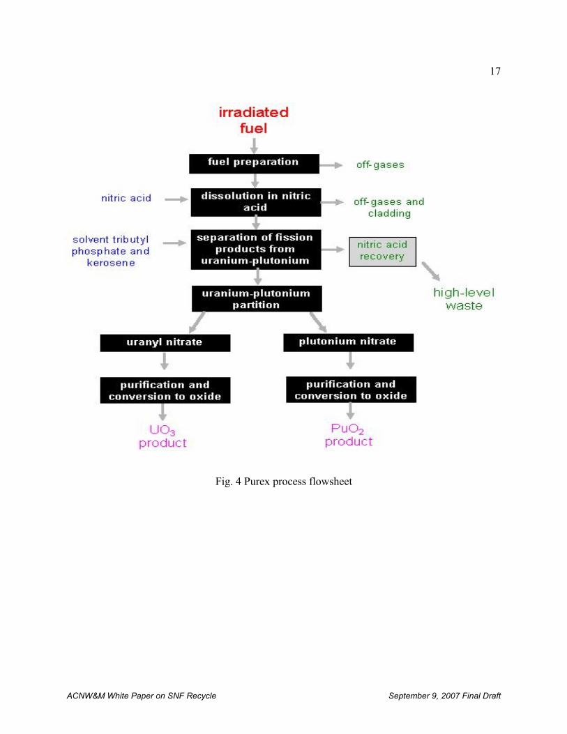
17
ACNW&M White Paper on SNF Recycle September 9, 2007 Final Draft
Fig. 4 Purex process flowsheet
18
ACNW&M White Paper on SNF Recycle September 9, 2007 Final Draft
b. U.S. Commercial reprocessing plants
In the early days of enthusiasm for nuclear energy in general, and spent nuclear fuel recycle inparticular, the U.S. government encouraged commercial spent fuel recycle both in the U.S. andoverseas. As a consequence there were several fuel reprocessing initiatives in the U.S. Theseare discussed briefly below.
i. Nuclear Fuel Services (NFS - West Valley Plant) – operated and being decommissioned
The Nuclear Fuel Services (NFS) West Valley reprocessing plant was a 300 metric tons of heavymetal/yr plant that operated in western New York from 1966 until 1972 [West Valley, 1981]. Using the PUREX Process the West Valley plant reprocessed about 650 metric tonnes of initialmetal (MTIHM), about 390 tons of which was metallic fuel from the Hanford plutoniumproduction reactors. Consequently the fuel had a very low burnup of around 2000 Mwd/tonne(to be contrasted with burnups of 45,000 Mwd/te for today’s LWR fuel). The remainder of thefuel reprocessed at the West Valley plant was uranium oxide fuel and fuel containing thorium. Because of seismic concerns and other issues that would have resulted in greatly increased cost,a planned expansion of the capacity of the West Valley plant was abandoned and the plant wasclosed.
ii. GE Morris, Il Plant – never operated
In 1967 the Atomic Energy Commission (AEC) authorized General Electric Co. to build areprocessing plant in Morris, IL. It was to employ a novel reprocessing method based on thevolatility of uranium hexafluoride to separate uranium from fission products and actinides. However, design and operational problems during process testing caused GE to halt constructionof the plant before it processed any spent fuel. However, it was radioactive as a result of testingbeing performed using uranium. Its spent fuel storage pond is currently used as an independentspent fuel storage installation (ISFSI) to store commercial spent nuclear reactor fuel.
iii. Barnwell Nuclear Fuel Plant – nearly completed; never operated
Construction of the Barnwell Nuclear Fuel Plant (BNFP) in Barnwell, SC, near the DOESavannah River site, began in 1970. The projected plant capacity was to be1500 MTIHM/yr. The plant design, which incorporated redundant cross piping to accommodate possible pipingfailures, was based on the PUREX process and is discussed in detail in an Appendix A. In 1976President Ford announced that “...reprocessing and recycling plutonium should not proceedunless there is a sound reason...” Presidents Carter’s veto in 1978 of S.1811, the EnergyResearch and Development Administration (ERDA) Authorization Act of 1978, and his decisionto defer indefinitely commercial spent fuel reprocessing effectively ended any chance forcommercial operation of the plant, and it was abandoned before operating with spent fuel (thusavoiding costly decommissioning).
2. International Reprocessing Plant Summary
Although the U.S. discontinued attempts at commercial spent fuel reprocessing in the mid-1970sthis did not deter construction and operation of reprocessing facilities worldwide. Table 1 [ISIS,2007] summarizes the capacity of civil (non-weapons) reprocessing plants that are operating orplanned.
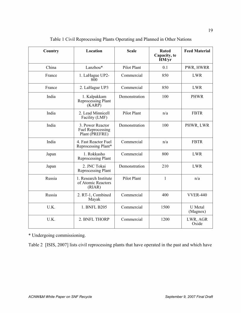
19
ACNW&M White Paper on SNF Recycle September 9, 2007 Final Draft
Table 1 Civil Reprocessing Plants Operating and Planned in Other Nations
Country Location Scale RatedCapacity, te
HM/yr
Feed Material
China Lanzhou* Pilot Plant 0.1 PWR, HWRR
France 1. LaHague UP2-800
Commercial 850 LWR
France 2. LaHague UP3 Commercial 850 LWR
India 1. KalpakkamReprocessing Plant
(KARP)
Demonstration 100 PHWR
India 2. Lead MinnicellFacility (LMF)
Pilot Plant n/a FBTR
India 3. Power ReactorFuel ReprocessingPlant (PREFRE)
Demonstration 100 PHWR, LWR
India 4. Fast Reactor FuelReprocessing Plant*
Commercial n/a FBTR
Japan 1. RokkashoReprocessing Plant
Commercial 800 LWR
Japan 2. JNC TokaiReprocessing Plant
Demonstration 210 LWR
Russia 1. Research Instituteof Atomic Reactors
(RIAR)
Pilot Plant 1 n/a
Russia 2. RT-1, CombinedMayak
Commercial 400 VVER-440
U.K. 1. BNFL B205 Commercial 1500 U Metal(Magnox)
U.K. 2. BNFL THORP Commercial 1200 LWR, AGROxide
* Undergoing commissioning.
Table 2 [ISIS, 2007] lists civil reprocessing plants that have operated in the past and which have
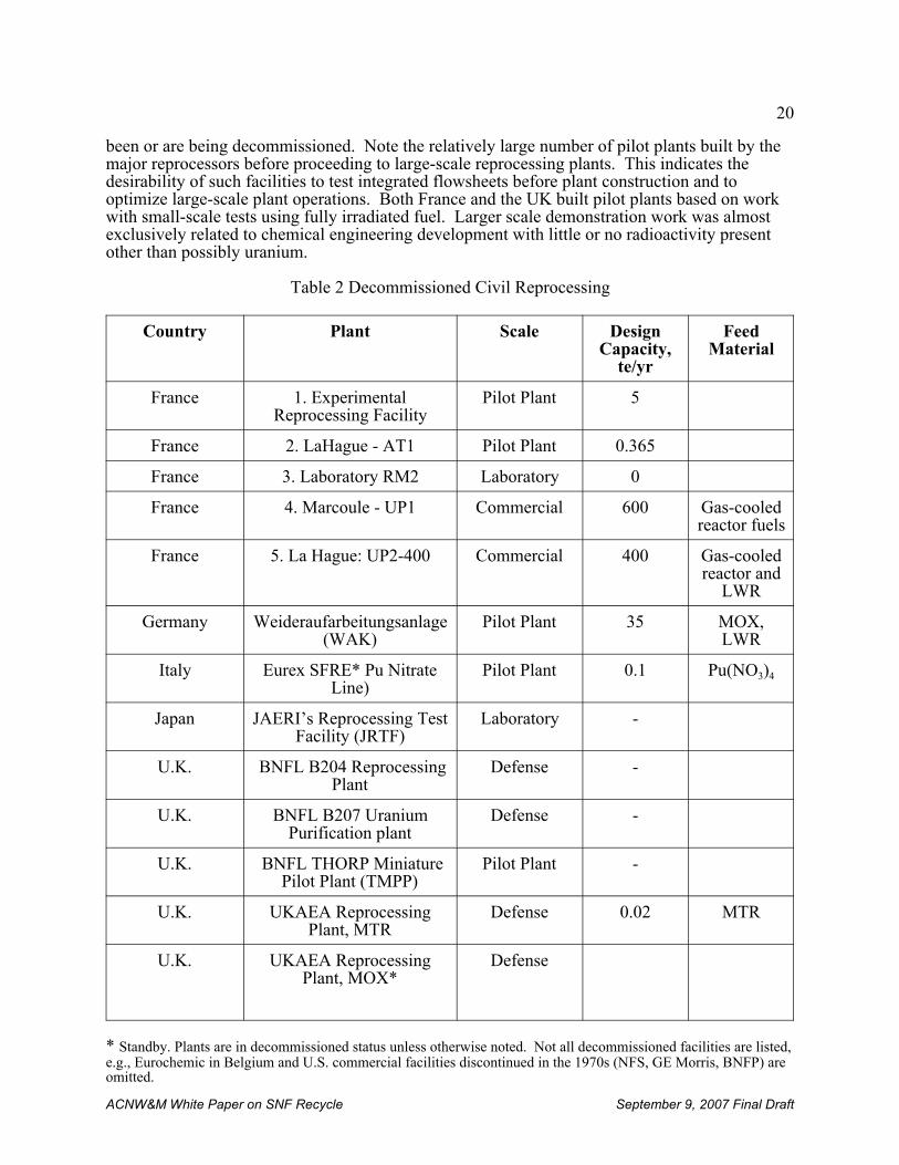
20
ACNW&M White Paper on SNF Recycle September 9, 2007 Final Draft
been or are being decommissioned. Note the relatively large number of pilot plants built by themajor reprocessors before proceeding to large-scale reprocessing plants. This indicates thedesirability of such facilities to test integrated flowsheets before plant construction and tooptimize large-scale plant operations. Both France and the UK built pilot plants based on workwith small-scale tests using fully irradiated fuel. Larger scale demonstration work was almostexclusively related to chemical engineering development with little or no radioactivity presentother than possibly uranium.
Table 2 Decommissioned Civil Reprocessing
Country Plant Scale DesignCapacity,
te/yr
FeedMaterial
France 1. ExperimentalReprocessing Facility
Pilot Plant 5
France 2. LaHague - AT1 Pilot Plant 0.365
France 3. Laboratory RM2 Laboratory 0
France 4. Marcoule - UP1 Commercial 600 Gas-cooledreactor fuels
France 5. La Hague: UP2-400 Commercial 400 Gas-cooledreactor and
LWR
Germany Weideraufarbeitungsanlage(WAK)
Pilot Plant 35 MOX,LWR
Italy Eurex SFRE* Pu NitrateLine)
Pilot Plant 0.1 Pu(NO3)4
Japan JAERI’s Reprocessing TestFacility (JRTF)
Laboratory -
U.K. BNFL B204 ReprocessingPlant
Defense -
U.K. BNFL B207 UraniumPurification plant
Defense -
U.K. BNFL THORP MiniaturePilot Plant (TMPP)
Pilot Plant -
U.K. UKAEA ReprocessingPlant, MTR
Defense 0.02 MTR
U.K. UKAEA ReprocessingPlant, MOX*
Defense
* Standby. Plants are in decommissioned status unless otherwise noted. Not all decommissioned facilities are listed,e.g., Eurochemic in Belgium and U.S. commercial facilities discontinued in the 1970s (NFS, GE Morris, BNFP) areomitted.
21
ACNW&M White Paper on SNF Recycle September 9, 2007 Final Draft
a. France
France has the largest LWR SNF reprocessing enterprise in the world. Commercial reprocessingis carried out at La Hague on the English Channel. La Hague reprocesses spent nuclear fuelfrom reactors belonging to French, European and Asian electricity companies. AREVA NC LaHague (formerly COGEMA) has two operating reprocessing plants at this site (UP2-800 andUP3) each having a design throughput of 850 metric tons of spent fuel per year. Uraniumdioxide, MOX, and research and test reactor fuels can be reprocessed at La Hague. For morethan 10 years La Hague reprocessing was split between the requirements of the French nuclearprogram (France’s 58 nuclear power plants, generating 76% of the country’s electricity) andthose of the 29 European and Japanese power companies that have reprocessing agreements withAREVA NC. Power companies from seven countries have sent or are sending spent fuel toAREVA NC La Hague (France, Japan, Germany, Belgium, Switzerland, Italy, and theNetherlands). From 1990 to 2005, close to 20,000 metric tons of fuel were reprocessed at the LaHague site.
The UP1 reprocessing plant at Marcoule, commissioned in 1958, reprocessed 18,600 metric tonsof spent fuel from gas-cooled reactors and research reactors to recover the reusable nuclearmaterials (uranium and plutonium). The site, located in southern France close to the Rhoneriver, reprocessed spent fuels for Commissariat à l’Ènergie Atomique (CEA) needs (G1, G2, G3reactors and Chinon 1). France’s commercial activities were initiated on the site in 1976, whenUP1 began reprocessing spent fuel from the French GCRs natural uranium-fueled reactors,which were graphite-moderated, gas-cooled reactors. COGEMA was created the same year, andtook over the operation of the UP1 plant. Production in the UP1 plant was terminated at the endof 1997 after 40 years of operation. Since 1998 the plant has been undergoing final shutdownoperations, to be followed by retrieval and repackaging of waste, then by dismantling anddecommissioning the plant.
b. Great Britain
Great Britain is the second largest reprocessor of power reactor spent fuel in the world. Reprocessing is carried out at the Windscale/Sellafield plant in the north-west of England on theIrish Sea. Civilian reprocessing began at Windscale in 1964, and is expected to continue until atleast 2015, about five years after the shut down of the last Magnox reactor in Britain. Magnoxpower-reactor fuel has been reprocessed at Windscale/Sellafield since 1964. Oxide fuelreprocessing began in 1969. Large scale oxide fuel reprocessing began with the commissioningin 1994 of the Thermal Oxide Reprocessing Plant (THORP; nominal capacity: 1200 metric tonsfuel per year). About 70 percent of the first ten years’ reprocessing at THORP was dedicated toforeign fuel. The British utility, British Energy, holds contracts to reprocess about 2600 metrictons of fuel, while additional contracts for 700 metric tons of fuel were signed by Germanutilities in 1990. In early 2005 THORP had processed almost 6000 metric tons of spent nuclearfuel containing about 1.7 billion curies of radioactivity. A diagram of the main THORPChemical Separation processes as it exists today is shown in Fig. 5.Detailed information on THORP Process Chemistry was provided by Energy Solutions forinclusion in this report and is presented in Sect. III.3.
Fast reactor and materials test reactor (MTR) fuel has been reprocessed at Dounreay in northernScotland since July 1958. This small reprocessing facility is now shut down and is undergoingdecommissioning.
22
ACNW&M White Paper on SNF Recycle September 9, 2007 Final Draft
c. Japan
Japan has a small reprocessing plant at Tokai-mura, with a design capacity of about 270 metrictons per year (0.7 te/day). (The actual annual reprocessing rate has been about 100 te/yr.) Construction of Japan’s first commercial reprocessing plant has been completed at Rokkasho-mura and testing for commercial start-up is underway. The plant, which is primarily of Frenchdesign, includes a number of buildings for the head-end process, separation and purification,uranium and plutonium co-denitration, high-level radioactive waste vitrification, and otherprocesses related to spent fuel recycle. The plant includes many French process improvementsto the PUREX process. The nominal reprocessing capacity of the plant is 800 tonne U/year,enough to reprocess the spent fuel produced by about thirty1,000 Mwe nuclear power stations.
d. Russia
The primary Russian reprocessing activity is at Mayak. The Mayak nuclear fuel reprocessingplant is between the towns of Kasli and Kyshtym (also transliterated Kishtym or Kishtim) 150 kmnorthwest of Chelyabinsk in Siberia. The plant is part of the Chelyabinsk Oblast.
In 1948 reprocessing irradiated fuel from the Russian plutonium production reactors began at theMayak plant. The plant underwent several modernizations and continued operation until theearly 1960s. Reprocessing irradiated fuel from the production reactors was continued at asecond plant located next to the first. (The second plant subsequently was combined into asingle industrial area called 235.) The second plant was adapted to extract isotopes fromirradiated targets from the Chelyabinsk-65’s isotope production reactors. In 1987, after two outof five production reactors were shut down, the second reprocessing plant was shut down.
Plant RT-1 was commissioned in 1977 to reprocess spent fuel from VVER-440, BN-350, BN-600, research, and naval propulsion reactors. Most of the feed is from VVER-440 reactors. Thisis the only Russian facility that reprocesses spent power reactor fuel. The plant’s nominalreprocessing capacity (based on spent fuel from the VVER-440 reactors) is 400 tons per year. The historical average throughput of spent fuel at RT-1 is estimated to be 200 MT of heavymetal per year. Since 1991 reprocessing of foreign spent fuel has become the main source ofrevenue for Mayak, and has served to cover the cost of domestic spent fuel reprocessing. Until1996, Mayak Production Association had contracts with nuclear utilities from Finland, Germany,Hungary, Ukraine, and Bulgaria. By 1996, however, Bulgaria, Germany, and Finland hadstopped using Mayak’s services.
e. India
Three reprocessing plants with a total design capacity of about 200 metric tons, none of which issafeguarded by IAEA, are operated by the Indian Department of Atomic Energy (DAE). Thefirst Indian reprocessing plant, at the Bhabha Atomic Research Centre (BARC) at Trombay,began operating in 1964 and has processed fuel from the Cirus and Dhruva research reactors. Itwas decommissioned in 1973 due to excessive corrosion, then refurbished and put back intoservice in 1982.
A second reprocessing plant, the Power Reactor Fuel Reprocessing (PREFRE) facility, dedicatedto reprocessing CANDU Zircaloy-clad oxide power reactor fuel, was brought into operation atTarapur in 1982. The design capacity of PREFRE is 100 metric tons of fuel per year. However,production at the plant has been constrained by logistical and technical problems. Furthermore,India has sought to avoid building plutonium stockpiles. In 1995, there was a serious leak of
23
11
INPRO is an IAEA program whose goal is to provide a “Methodology for Assessment of Innovative NuclearEnergy Systems as based on a defined set of Basic Principles, User Requirements and Criteria in the areas ofEconomics, Sustainability and Environment, Safety, Waste Management, Proliferation Resistance andrecommendations on Cross Cutting Issues.”
ACNW&M White Paper on SNF Recycle September 9, 2007 Final Draft
radioactivity at the waste immobilization plant associated with the Tarapur plant.
In March 1996 cold commissioning (operation without actual spent fuel) began at theKalpakkam Reprocessing Plant (KARP) located at the Indira Gandhi Centre for AtomicResearch (IGCAR) near Madras. ‘Hot’ commissioning, with the introduction of spent fuel, wasplanned for the end of 1996. Originally this site was planned to have 1,000 tons/year ofreprocessing capacity by the year 2000, but these plans are now in limbo. The facility iscurrently designed to have a capacity of 100 metric tons of CANDU fuel per year, for an annualoutput of about 350 kg of plutonium.
f. China
China plans to reprocess spent nuclear fuel, stating: “China will follow Japan’s lead and use theseparated plutonium to fuel fast-breeder reactors.” (Kitamura, 1999) China also plans to recyclemixed-oxide (MOX) fuel for use in its pressurized water reactors (PWRs) and fast reactors. TheChina National Nuclear Corporation (CNNC) has announced plans to construct a facility toreprocess spent fuel with a capacity of 400-800 tons per year, and China has pledged that its newplutonium extraction facilities will be open to international inspections. At present China has a0.1 tonne/yr pilot plant undergoing commissioning at Lanzhou for commercial spent fuelreprocessing.g. South Korea
It is not anticipated that South Korea will actually reprocess spent fuel or produce separatedplutonium. However, South Korea has a collaborative reprocessing program with Canada todevelop the DUPIC process. The DUPIC program is the subject of South Korea’s national casestudy for the IAEA’s INPRO11 project, evaluating new fuel cycle technologies. The DUPICprocess involves taking spent fuel from light water reactors, crushing it, heating it in oxygen tooxidize the UO2 to U3O8 (thus changing its crystal structure and pulverizing it) and drive offabout 40% of the fission products, (principally I, noble gases, tritium, Cs and Tc) and re-fabricating it into oxide fuel for pressurized heavy water reactors (PHWRs). The recycled fuelstill contains all the actinides, including a plutonium content of nearly 1% and about 96% of theuranium in the initial PWR fresh fuel, which typically contains several tenths of a percent U-235. Thus, the fissile content (239, 241Pu plus 235U) is around 1.5% - more than double that of naturaluranium (0.71 % 235U), and suitable for use in today’s Pressurized Heavy Water Reactors(PHWR).
3. THORP Reprocessing Plant PUREX Process
The THORP chemical separation plant was designed and constructed during the 1980s and early1990s with a nominal capacity of 1200 metric tons of SNF per year. The head end facilities wentinto hot operation in 1994 and the chemical plant followed in January, 1995. What follows is anoverview of the process chemistry of the chemical separation facilities in the THORP atSellafield (see Fig. 5) [Phillips, 2007; THORP, 2006; THORP, 1990a; THORP, 1984; THORP,1992; THORP, 1990b; THORP,1993; THORP, 1999a; THORP, 2000; THORP, 1999b]. Thisoverview emphasizes the extraction behavior and downstream redox consequences of 99Tc and
24
ACNW&M White Paper on SNF Recycle September 9, 2007 Final Draft
manipulation of neptunium valence which enables the effective decontamination of the uraniumand plutonium products in only two solvent
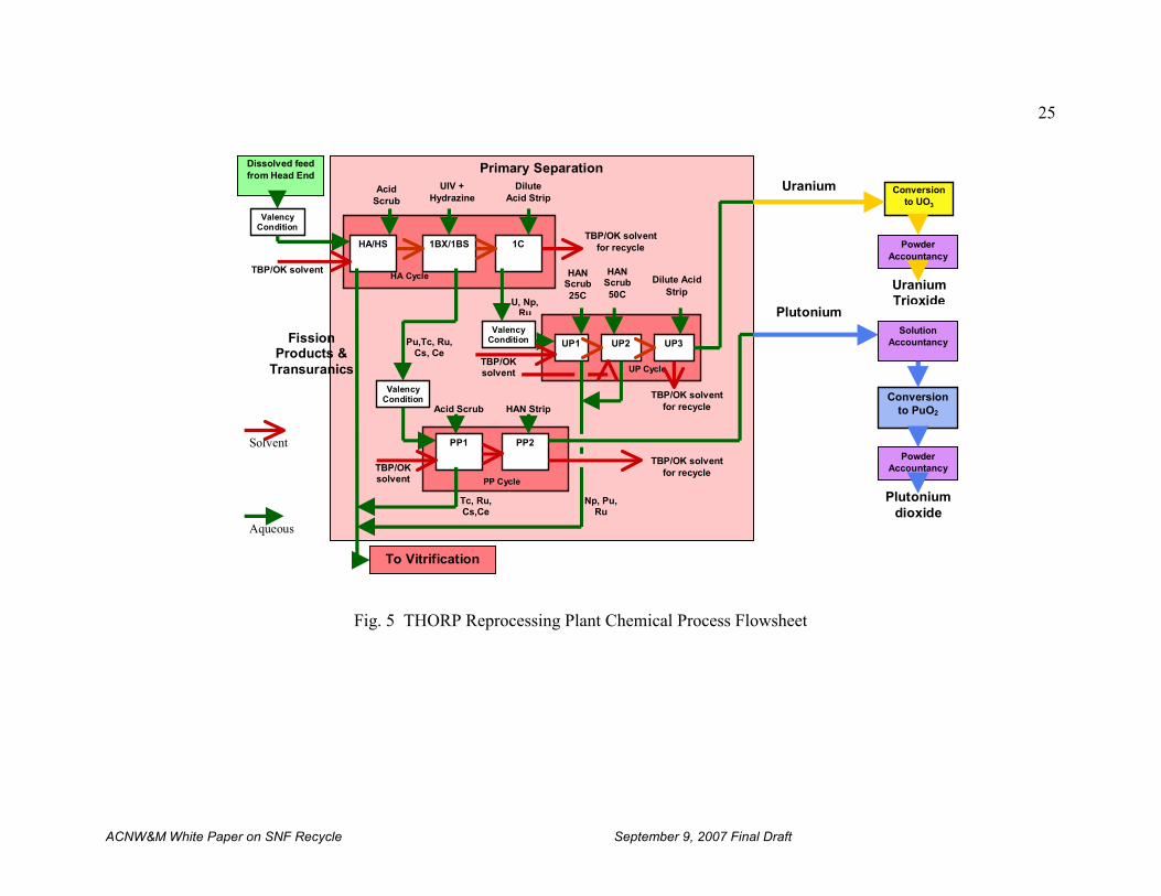
25
ACNW&M White Paper on SNF Recycle September 9, 2007 Final Draft
Fig. 5 THORP Reprocessing Plant Chemical Process Flowsheet
Primary Separation
HA Cycle
UP Cycle
PP Cycle
Np, Pu,Ru
Tc, Ru,Cs,Ce
Conversionto PuO2
UraniumTrioxide
Plutoniumdioxide
Conversionto UO3
Plutonium
FissionProducts &
Transuranics
Uranium
HA/HS 1BX/1BS 1C
AcidScrub
UIV +Hydrazine
DiluteAcid Strip
Dissolved feedfrom Head End
TBP/OK solvent
TBP/OK solventfor recycle
UP1 UP2 UP3
TBP/OKsolvent
ValencyCondition
HANScrub25C
PP1 PP2
Dilute AcidStrip
Acid Scrub HAN Strip
TBP/OK solventfor recycle
HANScrub50C
TBP/OK solventfor recycle
ValencyCondition
Pu,Tc, Ru,Cs, Ce
U, Np,Ru
ValencyCondition
PowderAccountancy
PowderAccountancy
SolutionAccountancy
To Vitrification
Solvent
TBP/OKsolvent
Aqueous
26
12 Raffinate is the term commonly given to the waste stream from a separation process. In solvent extractionprocesses it is the more dense aqueous stream containing waste materials. However, some confusion may arise inthe use of the term when there is an aqueous “waste” stream from one process step that is in fact a feed stream for astep that follows which is the case for UREX process flowsheets.
ACNW&M White Paper on SNF Recycle September 9, 2007 Final Draft
extraction cycles each. This reduction in number of cycles reduces capital and operating costs,and also reduces the amount of waste. The use of salt-free (degradable to nitrogen, oxygen, andwater) redox reagents also allows nearly all wastes to be evaporated to a small volume andvitrified.
a. Spent Nuclear Fuel Shearing and Dissolution
Spent nuclear fuel is sheared into 1-2 inch long segments and the fuel matrix is dissolved in oneof three batch dissolvers in the Head End plant. The dissolver solution is clarified by the removalof undissolved fission products in one of two centrifuges and then sent on to a series of threebuffer tanks of about 70 m3 capacity each. Here the dissolver solution is adjusted to 250 guranium per liter and 3M nitric acid, and treated with nitrogen oxides to ensure all the plutoniumis in the extractable [IV] valence state. Ideally the neptunium should be in the inextractableNp(V) state so that it is not extracted (i.e., it follows the fission product waste). In practice,about 67% is in the extractable Np(VI) state.
b. HA Cycle
The dissolver solution enters the HA pulse column at its mid point and flows downward againstan upward flowing stream of 30% TBP in odorless kerosene (TBP/OK). The uranium andplutonium quantitatively extract into the TBP/OK. About 67% of the neptunium also extracts. Almost 100% of the technetium extracts as a complex with zirconium.
The loaded solvent passes to the scrub section of the HA column and then onto the HS hot scrubpulse column, operated at 50EC to provide maximum decontamination from ruthenium. Theaqueous scrub solution is recycled to the HA column where it joins the dissolver solution andexits the bottom of the column as the HA aqueous raffinate12 (HAAR). The raffinate is steamstripped to remove organics, evaporated and sent to be vitrified.
The solvent containing U and Pu flows to the 1BX pulse column where it is contacted with anaqueous solution of U(IV) that has been chemically stabilized with hydrazine nitrate. Thisreduces the plutonium to the Pu(III) state so that it transfers to the aqueous phase. Under theseconditions the technetium also transfers almost completely to the aqueous phase, but ~64% ofthe neptunium in the feed stays with the uranium in the solvent. Some uranium also transfers tothe aqueous phase, so this phase passes to the 1BS pulsed column where the uranium is re-extracted and recycled back to the 1BX column. The aqueous solution of plutonium, technetiumand traces of uranium and neptunium go forward to the plutonium purification (PP) cycle. TheU[IV]/hydrazine reductant is “salt free” in that it disappears after use into gaseous products(hydrazine) and uranium. This allows all wastes to be concentrated into a small volume andvitrified.
The uranium-loaded solvent, together with the bulk of the neptunium, goes to the 1C Mixer
27
ACNW&M White Paper on SNF Recycle September 9, 2007 Final Draft
Settler. This back washes (strips) the uranium, neptunium, traces of plutonium and rutheniuminto a dilute nitric acid aqueous phase that goes to the uranium purification (UP) cycle. Thestripped solvent goes to a dedicated HA cycle solvent wash system and is recycled to the HAcolumn.
c. Plutonium Purification Cycle
The aqueous feed from the 1BS pulsed column is treated with oxides of nitrogen to convert theplutonium to the extractable Pu[IV] state, leaving the other components still inextractable. Thisstream passes to the PP1 pulse column where a fresh stream of 30% TBP/diluent extracts theplutonium, leaving the technetium and traces of ruthenium and neptunium in the raffinate. Ascrub section at the top of the PP1 column scrubs out any impurities that extracted along with theplutonium, with the scrub solution combining with the raffinate. This raffinate is salt free andcan be combined with the HAAR and sent to vitrification.
The plutonium-loaded solvent goes to the PP2 pulse column where it is contacted with anaqueous solution of hydroxylamine nitrate (HAN). HAN is an effective plutonium reducingagent under the lower acid conditions in the PP cycle, and its use avoids the use of U(IV), whichsome other flowsheets use for plutonium reduction, and which would re-contaminate the purifiedplutonium with uranium. The plutonium is reduced to Pu(III), transfers to the aqueous streamand goes to plutonium dioxide production. The stripped solvent goes to a dedicated PP Cyclesolvent wash system and is recycled to the PP1 column.
d. Uranium Purification Cycle
The aqueous feed from the 1C mixer settler is conditioned at a specific temperature and acidity,and for a residence time that laboratory testing showed would produce near 100% inextractableNp(V). It is then fed to the UP1 mixer settler, where the uranium is extracted into 20%TBP/diluent solvent. Neptunium stays in the UP1 aqueous raffinate. A carefully controlledHAN scrub feed is used to reduce the plutonium to Pu(III) and thus prevent its extraction, whilenot reducing the neptunium to the extractable Np(IV) state. The uranium-loaded solvent, withtraces of plutonium and ruthenium passes to the UP2 mixer-settler where, in the absence ofneptunium, higher concentrations of HAN and higher temperatures can be used to remove theplutonium and ruthenium traces from the solvent into the UP2AR. Because this also causes somestripping of uranium, fresh solvent is fed to the uranium re-extraction section of UP2 to re-extract this uranium and combine it with the solvent from UP1. The aqueous raffinates fromboth UP1 and UP2 are salt-free and are routed to evaporation and vitrification along with HAARand PP1AR.
The uranium-loaded solvent passes to the UP3 backwash (strip) contactor where dilute nitricacid is used to strip the uranium from the solvent. The stripped solvent goes to a dedicated UPcycle solvent wash process and is then recycled to UP1 and UP2.
e. Separation Performance of THORP
The performance of THORP chemical separation has been reported in a series of conference
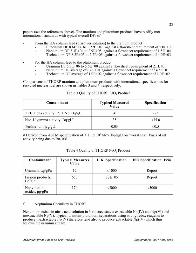
28
ACNW&M White Paper on SNF Recycle September 9, 2007 Final Draft
papers (see the references above). The uranium and plutonium products have readily metinternational standards with typical overall DFs of:
• From the HA column feed (dissolver solution) to the uranium product- Plutonium DF 8.6E+06 to 1.22E+10, against a flowsheet requirement of 5.0E+06- Neptunium DF 3.3E+04 to 2.9E+05, against a flowsheet requirement of 1.5E+04- Technetium DF 8.2E+03 to 2.2E+05 against a flowsheet requirement of 4.0E+03
• For the HA column feed to the plutonium product- Uranium DF 5.8E+06 to 5.6E+08 against a flowsheet requirement of 2.1E+05- Neptunium DF average of 6.6E+01 against a flowsheet requirement of 4.5E+01- Technetium DF average of 1.0E+02 against a flowsheet requirement of 1.0E+02
Comparisons of THORP uranium and plutonium products with international specifications forrecycled nuclear fuel are shown in Tables 3 and 4, respectively.
Table 3 Quality of THORP UO3 Product
Contaminant Typical MeasuredValue
Specification
TRU alpha activity: Pu + Np, Bq/gU 4 #25
Non-U gamma activity, Bq/gU# 35 #35.0
Technetium, :g/gU 0.03 #0.5
# Derived from ASTM specification of < 1.1 x 10⁵ MeV Bq/kgU on “worst case” basis of allactivity being due to Ru-106.
Table 4 Quality of THORP PuO2 Product
Contaminant Typical MeasuresValue
U.K. Specification ISO Specification, 1996
Uranium, :g/gPu 12 #1000 Report
Fission products,Bq/gPu
650 #3E+05 Report
Nonvolatileoxides, μg/gPu
170 #5000 #5000
f. Neptunium Chemistry in THORP
Neptunium exists in nitric acid solution in 3 valence states: extractable Np(IV) and Np(VI) andinextractable Np(V). Typical uranium-plutonium separations using strong redox reagents toproduce inextractable Pu(IV) therefore tend also to produce extractable Np(IV) which thusfollows the uranium stream.
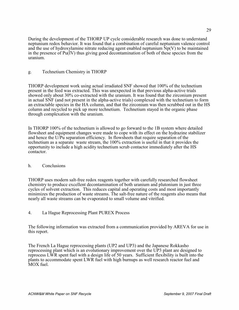
29
ACNW&M White Paper on SNF Recycle September 9, 2007 Final Draft
During the development of the THORP UP cycle considerable research was done to understandneptunium redox behavior. It was found that a combination of careful neptunium valence controland the use of hydroxylamine nitrate reducing agent enabled neptunium Np(V) to be maintainedin the presence of Pu(IV) thus giving good decontamination of both of these species from theuranium.
g. Technetium Chemistry in THORP
THORP development work using actual irradiated SNF showed that 100% of the technetiumpresent in the feed was extracted. This was unexpected in that previous alpha-active trialsshowed only about 30% co-extracted with the uranium. It was found that the zirconium presentin actual SNF (and not present in the alpha-active trials) complexed with the technetium to forman extractable species in the HA column, and that the zirconium was then scrubbed out in the HScolumn and recycled to pick up more technetium. Technetium stayed in the organic phasethrough complexation with the uranium.
In THORP 100% of the technetium is allowed to go forward to the 1B system where detailedflowsheet and equipment changes were made to cope with its effect on the hydrazine stabilizerand hence the U/Pu separation efficiency. In flowsheets that require separation of thetechnetium as a separate waste stream, the 100% extraction is useful in that it provides theopportunity to include a high acidity technetium scrub contactor immediately after the HScontactor.
h. Conclusions
THORP uses modern salt-free redox reagents together with carefully researched flowsheetchemistry to produce excellent decontamination of both uranium and plutonium in just threecycles of solvent extraction. This reduces capital and operating costs and most importantlyminimizes the production of waste streams. The salt-free nature of the reagents also means thatnearly all waste streams can be evaporated to small volume and vitrified.
4. La Hague Reprocessing Plant PUREX Process
The following information was extracted from a communication provided by AREVA for use inthis report.
The French La Hague reprocessing plants (UP2 and UP3) and the Japanese Rokkashoreprocessing plant which is an evolutionary improvement over the UP3 plant are designed toreprocess LWR spent fuel with a design life of 50 years. Sufficient flexibility is built into theplants to accommodate spent LWR fuel with high burnups as well research reactor fuel andMOX fuel.
30
13 The U.S. does not have an ILW classification. Such wastes would typically be GTCC LLW
ACNW&M White Paper on SNF Recycle September 9, 2007 Final Draft
The La Hague reprocessing process steps are basically the same as those in all reprocessingplants. However, there are substantial process differences among the plants based on operatingexperience and preference. The La Hague plant UP3 process steps are discussed below:
a. Spent fuel receiving and storage
Two spent fuel unloading processes are used in the AREVA La Hague plant: under-waterunloading designed for 110 casks/year and dry unloading designed tor 245 casks/year.
Dry unloading has the advantages of reducing worker radiation dose, quicker unloading, and afive-fold reduction of effluents per cask unloading
The La Hague spent fuel storage capacity is approximately 14,000 MTHM, which is about eighttimes the plant annual spent fuel treatment capacity.
b. Shearing and dissolution
Spent fuel assemblies are cut into segments with a shearing machine that is located above acontinuous dissolver. The pieces fall into a perforated basket in the dissolver where the fuelmatrix dissolves in nitric acid but the cladding does not. The dissolver design is geometricallysafe to avoid inadvertent criticality. When MOX fuel is dissolved a neutron poison is added tothe solution. Cladding hulls are rinsed and sent to a facility for compaction and conditioning asIntermediate Level Waste (ILW)13. Any residual solids remaining in the dissolver solution areremoved by centrifugation.
The following improvements to the shearing and dissolution steps are being pursued:
• Techniques for managing precipitates in the dissolver and development of chemical andmechanical processes to clean the dissolving equipment,
• Better understanding of corrosion to establish a proven and significant life-time for theprincipal dissolving equipment,
• Adaptation of reprocessing facilities to accommodate higher burnup fuel, MOX fuel,research and test reactor fuel, and unirradiated FBR fuel.
c. U/Pu solvent extraction separation and purification
Solvent extraction with TBP in a branched dodecane diluent is used to remove uranium andplutonium from other actinides and from fission products. A nitric acid scrub is used to removeimpurities carried into the TBP. Two extraction cycles in pulse columns, mixer-settlers, orcentrifugal contactors are needed to meet product specifications. At the end of the extraction,scrubbing, and stripping cycles the following solutions are produced:
31
14The Rokkasho reprocessing plan in Japan also has three solvent extraction cycles.
ACNW&M White Paper on SNF Recycle September 9, 2007 Final Draft
• uranyl nitrate,
• plutonium nitrate,
• raffinates containing most non-volatile fission products and the minor actinides,
• the TBP/diluent solvent, which is regenerated by treatment to remove impurities andrecycled.
Particular attention was paid to solvent cleanup. Vacuum distillation was a major innovationthat insured purification of used solvent for recycle back into the process line. Pulse columnswere selected for use in the most highly radioactive parts of the plant, mainly to comply withcriticality safety requirements. Pulse columns for solvent extraction were superior to mixer-settlers due to the shorter residence time of radioactivity in pulse columns. This led to drasticreductions of solvent degradation and to improved management of interfacial cruds.
The UP2-800 La Hague plant14 has 3 extraction cycles: one for co-decontamination andseparation of U and Pu, and one each for further purification of U and Pu. One alkaline solventregeneration unit is associated with the U and Pu cycles. Organic wastes are recycled aftercleanup by vacuum distillation. The UP3 plant was initially commissioned with two uraniumpurification cycles. It subsequently became apparent that increased understanding of solventextraction chemistry and better process control made the second uranium purification cycleuneccessary. The second cycle ceased operation in 1994. The original and present UP3 solventextraction cycles are shown in Fig. 6.
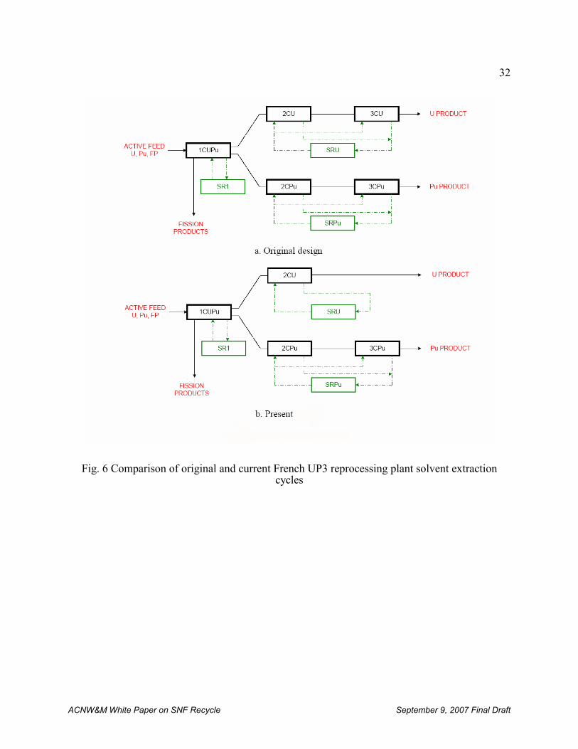
32
ACNW&M White Paper on SNF Recycle September 9, 2007 Final Draft
Fig. 6 Comparison of original and current French UP3 reprocessing plant solvent extractioncycles
33
ACNW&M White Paper on SNF Recycle September 9, 2007 Final Draft
d. Conversion of U and Pu to products
The U solution is concentrated by evaporation, stored, and eventually converted to UF6 forsubsequent re-enrichment or to UF6 for storage. The Pu is precipitated as the oxalate by theaddition of oxalic acid. The precipitate is filtered, dried, and calcined to form PuO2 that meetsthe specifications for making MOX fuel. The mother liquor containing dissolved or suspendedPu, is concentrated and recycled.
e. Management and treatment of process wastes
Process waste streams include:
• hulls and end pieces from the dissolver that are compacted for final disposal
• high-activity liquid waste streams containing:
- suspended particles from feed clarification,
- fission products and minor actinides,
- concentrates generated by evaporation in the acid recovery units.
The various streams, except the suspended particles, are concentrated and stored in tanks fittedwith cooling and pulse devices to keep solids suspended. The concentrates are mixed with theparticles and vitrified to form a glass waste form.
f. Radioelements released
The principle radioelements released from the plant are:
• Tritium: most of the tritium is trapped in tritiated water that is released to the sea;
• About a third of the 14C, which is present as CO2, is scrubbed from the off-gas by passingit through a sodium hydroxide solution, diluted in tritiated water, and released to the seawith the remaining two-thirds being released to the atmosphere;
• Most of the iodine (129I is the isotope of concern) is scrubbed by passing it through asodium hydroxide solution which is released to the sea. Any remaining gaseous iodine istrapped in filters;
• 85Kr is not removed from the off-gas stream;
• Aerosols are trapped on filters with a 99.9% efficiency. Ruthenium in vitrification off-gas aerosols is removed by injection of nitrogen oxides before being released. Aerosolsreleased from the facility consist mainly of ruthenium and antimony.
34
ACNW&M White Paper on SNF Recycle September 9, 2007 Final Draft
Radionuclide releases from the La Hague plant are given in Tables 17 and 18.
5. Accidents at Spent Fuel Reprocessing Facilities
a. Sellafield Facility [Schneider, 2001]
In 1973 there was a release of radioactive material following an exothermal chemical reaction ina reprocessing tank in the Windscale plant. This accident involved a release of radioactivematerial into a plant operating area.
In 2005 a radioactive leak from a pipe between the dissolver and a tank in the THORP fuelreprocessing plant was detected. This resulted in an extended shutdown of the facility forrepairs, government investigations, fines, and potentially legal charges against plant managers.
b. La Hague Facility [Schneider, 2001]
On October 2, 1968 129I was released through the UP2-400 stack. This accident was caused bythe treatment of insufficiently cooled gas-graphite fuels.
On January 14, 1970 the temperature of the chemical dissolution reaction of graphite fuelincreased sharply and an explosion due to hydrogen gas caused a release to occur. 129I was alsoreleased.
On January 2, 1980 there was a leak 200m from shore through a 1-meter crack in the La Haguedischarge pipe that extends kilometers out to sea.
On February 13, 1990 there was an uncontrolled release of 137Cs by the ELAN II B plantchimney. A routine replacement of a chimney filters led to the release of non-filtered andcontaminated air for 10 minutes.
Since 1983: Corrosion of metallic waste stored in concrete pools that leaked resulted in releaseof radionuclides to groundwater and near-by streams with 90Sr being the most prominent.
c. Mayak [Azizova, 2005]
In 1957 one of the concrete HLW waste storage tanks’ cooling systems broke down permittingthe tank contents to go dry and overheat. Chemical reaction of dry nitrate and acetate salts in thewaste tank containing highly active waste caused an explosion that contaminated an area latercalled the "Kyshtym footprint."
35
ACNW&M White Paper on SNF Recycle September 9, 2007 Final Draft
On April 6, 1993 a tank containing a solution of paraffin hydrocarbon and TBP used todecontaminate spent nuclear reactor fuel exploded. The resulting explosion was strong enoughto knock down walls on two floors of the facility and caused a fire.
d. Tokai reprocessing plant [NNI, 1997]
In March 1997 a fire and an explosion occurred at the Tokai waste bitumenization facility. Theaccident contaminated 37 workers and an area of 1 km2 around the plant was evacuated.
e. International Nuclear Event Scale and Accident Classification
Table 5 [IAEA, 2001] shows the existing International Nuclear Event Scale listed on a scale of 1to 7 to indicate the severity of a nuclear accident or incident, along with a description of thenature of the event, which is currently used to categorize such events. It should be noted that useof this scale needs to consider the relative risk from radionuclides as compared to 131I todetermine the category of an event. The International Nuclear Event Scale is presentlyundergoing revision [IAEA, 2007b]. Table 6 [Schneider, 2001] gives specific examples ofaccidents that have occurred.
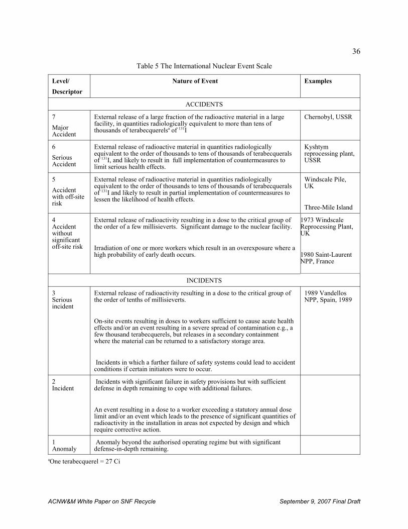
36
ACNW&M White Paper on SNF Recycle September 9, 2007 Final Draft
Table 5 The International Nuclear Event Scale
Level/
Descriptor
Nature of Event Examples
ACCIDENTS
7
MajorAccident
External release of a large fraction of the radioactive material in a largefacility, in quantities radiologically equivalent to more than tens ofthousands of terabecquerelsa of 131I
Chernobyl, USSR
6
SeriousAccident
External release of radioactive material in quantities radiologically equivalent to the order of thousands to tens of thousands of terabecqueralsof 131I, and likely to result in full implementation of countermeasures tolimit serious health effects.
Kyshtymreprocessing plant,USSR
5
Accidentwith off-siterisk
External release of radioactive material in quantities radiologically equivalent to the order of thousands to tens of thousands of terabecqueralsof 131I and likely to result in partial implementation of countermeasures tolessen the likelihood of health effects.
Windscale Pile,UK
Three-Mile Island
4Accidentwithoutsignificantoff-site risk
External release of radioactivity resulting in a dose to the critical group ofthe order of a few millisieverts. Significant damage to the nuclear facility.
Irradiation of one or more workers which result in an overexposure where ahigh probability of early death occurs.
1973 WindscaleReprocessing Plant,UK
1980 Saint-LaurentNPP, France
INCIDENTS
3Seriousincident
External release of radioactivity resulting in a dose to the critical group ofthe order of tenths of millisieverts.
On-site events resulting in doses to workers sufficient to cause acute healtheffects and/or an event resulting in a severe spread of contamination e.g., afew thousand terabecquerels, but releases in a secondary containmentwhere the material can be returned to a satisfactory storage area.
Incidents in which a further failure of safety systems could lead to accidentconditions if certain initiators were to occur.
1989 VandellosNPP, Spain, 1989
2Incident
Incidents with significant failure in safety provisions but with sufficientdefense in depth remaining to cope with additional failures.
An event resulting in a dose to a worker exceeding a statutory annual doselimit and/or an event which leads to the presence of significant quantities ofradioactivity in the installation in areas not expected by design and whichrequire corrective action.
1Anomaly
Anomaly beyond the authorised operating regime but with significantdefense-in-depth remaining.
aOne terabecquerel = 27 Ci
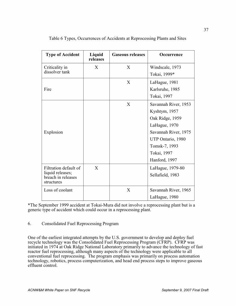
37
ACNW&M White Paper on SNF Recycle September 9, 2007 Final Draft
Table 6 Types, Occurrences of Accidents at Reprocessing Plants and Sites
Type of Accident Liquidreleases
Gaseous releases Occurrence
Criticality indissolver tank
X X Windscale, 1973
Tokai, 1999*
Fire
X LaHague, 1981
Karlsruhe, 1985
Tokai, 1997
Explosion
X Savannah River, 1953
Kyshtym, 1957
Oak Ridge, 1959
LaHague, 1970
Savannah River, 1975
UTP Ontario, 1980
Tomsk-7, 1993
Tokai, 1997
Hanford, 1997
Filtration default ofliquid releases;breach in releasesstructures
X LaHague, 1979-80
Sellafield, 1983
Loss of coolant X Savannah River, 1965
LaHague, 1980
*The September 1999 accident at Tokai-Mura did not involve a reprocessing plant but is ageneric type of accident which could occur in a reprocessing plant.
6. Consolidated Fuel Reprocessing Program
One of the earliest integrated attempts by the U.S. government to develop and deploy fuelrecycle technology was the Consolidated Fuel Reprocessing Program (CFRP). CFRP wasinitiated in 1974 at Oak Ridge National Laboratory primarily to advance the technology of fastreactor fuel reprocessing, although many aspects of the technology were applicable to allconventional fuel reprocessing. The program emphasis was primarily on process automationtechnology, robotics, process computerization, and head end process steps to improve gaseouseffluent control.
38
ACNW&M White Paper on SNF Recycle September 9, 2007 Final Draft
Automation technology has been widely adopted in the manufacturing industry and in thechemical processing industries, but until recently only to a limited extent in nuclear fuelreprocessing. It does, however, find wide use in the manufacture of commercial light waterreactor fuel fabrication. This is especially true in the chemical conversion process for uranium. The effective use of automation in reprocessing had been limited by the lack of diverse andreliable process instrumentation and the general unavailability of sophisticated computersoftware designed specifically for reprocessing plant process control.
A new facility, the Integrated Equipment Test (IET) facility, was developed by the CFRP in partto demonstrate new concepts for control of advanced nuclear fuel reprocessing plants usingadvanced instrumentation and a modern, microprocessor-based control system. The IETconsisted of the Integrated Process Demonstration (IPD) and the Remote Operations andMaintenance Demonstration (ROMD). The IPD focused on demonstration of state-of-the-artequipment and processes, improved safeguards and accountability, low-flow cell ventilation,advances in criticality safety and operability, and new concepts for control of advanced nuclearfuel reprocessing plants using advanced instrumentation and a modern, microprocessor-basedcontrol system. The ROMD served as a test bed for fully remote operations and maintenanceconcepts and improved facility layout and equipment rack designs. This facility provided fortesting of all chemical process features of a prototypical fuel reprocessing plant that can bedemonstrated with unirradiated uranium-bearing feed materials. The goal was demonstration ofthe plant automation concept and development of techniques for similar applications in a full-scale plant. It was hoped that the automation work in the IET facility would be useful to othersin reprocessing by helping to avoid costly mistakes caused by the under-utilization ormisapplication of process automation.
During the 1970s and 1980s CFRP was a leader in advancing technology used in fuelreprocessing. Numerous interactions were established with foreign governments such as UnitedKingdom, France, Germany, Japan, Russia and Korea to share information and establish policy.
Eventually the CFRP became reliant on the infusion of money from the Japanese nuclearenterprise and on-site Japanese technical personnel for survival. Because of the moratoriumimposed by the Carter administration on U.S. reprocessing, much of the U.S.-supported CFRPtechnology that was developed has to date found more application in Japan than it has found inthe U.S.
7. International Nuclear Fuel Cycle Evaluation (INFCE)
President Carter’s April 1977 statement on nuclear policy that made a commitment to deferindefinitely the commercial reprocessing and recycling of plutonium – coupled with low pricesfor fossil fuels and uranium – effectively ended consideration of non-defence reprocessing andrecycle activities in the U.S. for decades. However, the immediate result of the deferral was theinitiation of a series of studies to evaluate the need for reprocessing and plutonium recycle. Thelargest of these was the International Nuclear Fuel Cycle Evaluation (INFCE).
INFCE addressed essentially all the important technical issues related to fuel recycle. In October
39
ACNW&M White Paper on SNF Recycle September 9, 2007 Final Draft
1977 the International Nuclear Fuel Cycle Evaluation Committee was initiated, mainly at theurging of the U.S., to investigate opportunities to safely internationalize the nuclear fuel cycle. INFCE participants met between 1977 and 1980 to address ways to use the nuclear fuel cycle toproduce nuclear energy with a reduced risk of nuclear proliferation by modifying the fuel cycletechnological base. INFCE highlighted a number of measures to counter the dangers of nuclearproliferation, including institutional and technical measures, as well as improvement and furtherdevelopment of International Atomic Energy Agency (IAEA) safeguards. Subsequent toINFCE, reprocessing of spent nuclear fuel and recycle of the resulting nuclear materials wasvirtually ignored in the U.S. until the turn of the century.
a. Content of the INFCE Study
INFCE focused on: 1) an overall assessment of the nuclear fuel cycle, 2) measures to improveassurances of availability of plutonium supply for reactor fuels to developing states, 3) spentnuclear fuel storage, 4) improvements to nuclear safeguards, and 5) alternatives to aninternational nuclear economy based on plutonium and highly-enriched uranium fuels. Concernabout introduction of an international plutonium economy led the IAEA in 1978 to establish aCommittee on International Plutonium Storage (IPS). Establishment of the IPS was the principlerecommendation of INFCE.
b. Principle Conclusions
The report of INFCE Working Group 4 [INFCE, 1980], one of eight INFCE Working Groups,discussed reprocessing, plutonium handling, and recycle of plutonium to thermal reactors. Fastreactor recycle was left to Working Group 5, and other fuel recycle concepts, e.g., thorium-basedand research reactor fuels, were left to Working Group 8. The basic recommendation of INFCEwas to deposit plutonium surplus to national needs with the IAEA. In this strategy forcontrolling plutonium it was envisioned that excess plutonium would be placed underinternational inspection and control until needed for use in civil nuclear power applications.
B. Fuel Fabrication and Refabrication
Fabrication of fresh and refabrication of fuel from reprocessed spent nuclear fuel is ainternational industry. A recent IAEA publication [IAEA, 2007a] gives information on both thecharacteristics (e.g., the 99Tc concentration) and the specifications of reprocessed UO3.
1. Fuel Refabrication Technology
LWR reactor fuels are of two types: 1) low-enriched uranium oxide and 2) mixed uranium-plutonium oxides (MOX). The uranium oxide fuels are much more common, but as moreplutonium becomes available MOX fuels, in combination with uranium oxide fuel, are becomingmore common. Both fuel types are made from what is essentially the dioxides of the two fissilemetallic components.
40
ACNW&M White Paper on SNF Recycle September 9, 2007 Final Draft
For UO2 pellet material fabrication uranyl nitrate solution is denitrated in a fluidized bed orrotary kiln to form UO2. Plutonium nitrate solutions are treated in a manner similar to uranylnitrate solutions if PuO2 is sought. For MOX fuel material preparation uranium and plutoniumoxide powders are blended or uranium and plutonium solutions are mixed, concentrated, andsimultaneously denitrated (by microwave heating) to produce a mixed U/PU oxide (MOX). UO2+x, PuO2+x and MOX are then treated by the following steps.
a. They are calcined in air at 800 º C.
b. The calcined product is heated in a reduction furnace in H2/N2 at 800 º C. toproduce UO2, PuO2 or MOX fuel material suitable for pellet fabrication. (Thistwo-step reduction saves hydrogen.)
c. The powders are blended when appropriate and mixed with volatile binders.
d. After pressing and sintering to form pellets the pellets are ground to meet specifications.
e. The LWR fuel pellets are inserted into Zircaloy cladding tubes which are groupedinto a square array with grid spacers and held together with two stainless steel endpieces connected by empty tie rods. Zircaloy, an alloy of zirconium, is used forneutron economy. It has a low cross section for capture of neutrons in the thermalneutron energy spectrum found in LWR cores.
f. Fast reactor fuel is fabricated using stainless steel cladding and hardware. Stainless steel is suitable for use with liquid metal coolants and where thetemperature is high. (Neutron economy is not as important in fast reactors wherethe neutron energy is higher than in LWRs resulting in smaller neutron absorptioncross sections.)
The steps in a conventional MOX fuel refabrication are shown diagrammatically in Figure 7. Other refabrication processes have been developed and deployed. These processes typicallydiffer in the details of how the uranium and plutonium oxide powders are blended and aresummarized in [IAEA, 2003a].
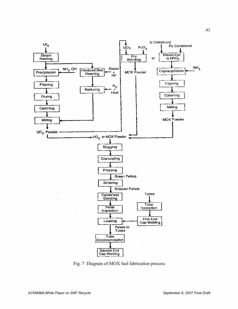
41
ACNW&M White Paper on SNF Recycle September 9, 2007 Final Draft
Fig. 7 Diagram of MOX fuel fabrication process
42
15 In sol-gel processes a colloidal suspension (sol) is “gelled” to form a solid by extraction of water and addition of amild chemical base. When carried out using droplets of sol, spherical gelled particles are formed.
ACNW&M White Paper on SNF Recycle September 9, 2007 Final Draft
2. MOX Fuel Fabrication Facilities
Some of the plutonium recovered by reprocessing is being fabricated into mixed oxide (MOX)fuel. Table 7 [ISIS, 2007] lists the capacity and status of MOX fuel fabrication plantsworldwide.
In addition to the MOX fabrication plants listed in Table 7, the U.S. DOE has a MOX plantunder construction at the Savannah River site in South Carolina. The current plan is for thefacility to be built as part of the national strategy to dispose of excess weapons-grade plutoniumby using it for commercial power production. According to the plan the facility would be usedonly for the purpose of disposition of surplus plutonium and is subject to Nuclear RegulatoryCommission (NRC) licensing. The current plan is for the facility to be shut down when theweapons plutonium disposition is completed.
A recent IAEA document provides details of MOX fuel fabrication world-wide [IAEA, 2003a].
3. HTGR Fuel Fabrication
HTGR fuel is very different from other types of solid reactor fuels, and fabricating HTGR fuel isentirely different from fabricating LWR or fast reactor fuels. Both Germany and the U.S. havedeveloped HTGR fuel fabrication processes for HTGR TRISO fuel particle (see Sect. II.B.1)preparation that consist of a number of similar steps. In both countries kernels containing thefissile material are made via a sol-gel process15, followed by washing, drying and calcining toproduce spherical UO2 kernels (in Germany) and UCO kernels (in the US). The major differencein tne processes consists of a sintering step using CO in the U.S. process to ensure the requisiteC/O stoichiometry in the kernel. The coating processes for the inner porous “buffer” layer aresimilar, based on chemical vapor deposition from a mixture of Ar and acetylene in a fluidizedcoater operating between 1250 and 1300 EC. A 5-micron seal coat is added in the U.S. processto seal the porous buffer coating. This step does not occur in the German process. Table 8 givestypical properties of coated fuel particles and pebbles. Figure 8 is a schematic diagram andphotograph of TRISO fuel particles.
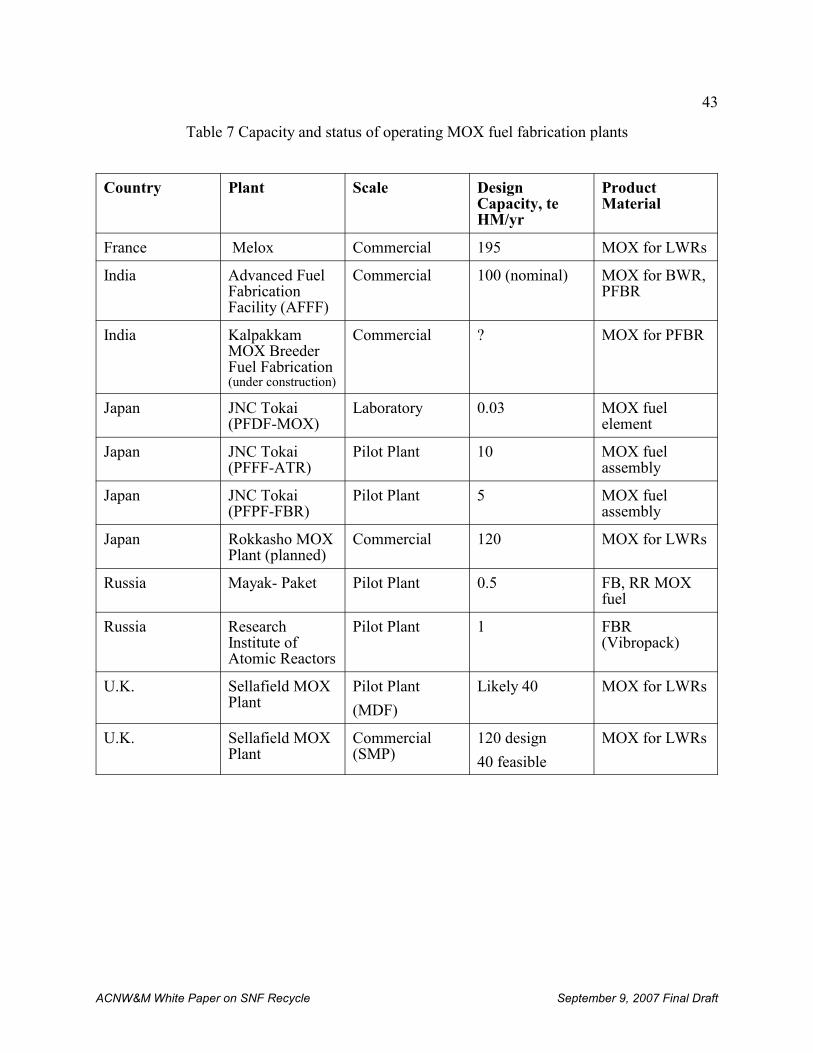
43
ACNW&M White Paper on SNF Recycle September 9, 2007 Final Draft
Table 7 Capacity and status of operating MOX fuel fabrication plants
Country Plant Scale DesignCapacity, teHM/yr
ProductMaterial
France Melox Commercial 195 MOX for LWRs
India Advanced FuelFabricationFacility (AFFF)
Commercial 100 (nominal) MOX for BWR,PFBR
India KalpakkamMOX BreederFuel Fabrication(under construction)
Commercial ? MOX for PFBR
Japan JNC Tokai(PFDF-MOX)
Laboratory 0.03 MOX fuelelement
Japan JNC Tokai(PFFF-ATR)
Pilot Plant 10 MOX fuelassembly
Japan JNC Tokai(PFPF-FBR)
Pilot Plant 5 MOX fuelassembly
Japan Rokkasho MOXPlant (planned)
Commercial 120 MOX for LWRs
Russia Mayak- Paket Pilot Plant 0.5 FB, RR MOXfuel
Russia ResearchInstitute ofAtomic Reactors
Pilot Plant 1 FBR(Vibropack)
U.K. Sellafield MOXPlant
Pilot Plant
(MDF)
Likely 40 MOX for LWRs
U.K. Sellafield MOXPlant
Commercial(SMP)
120 design
40 feasible
MOX for LWRs
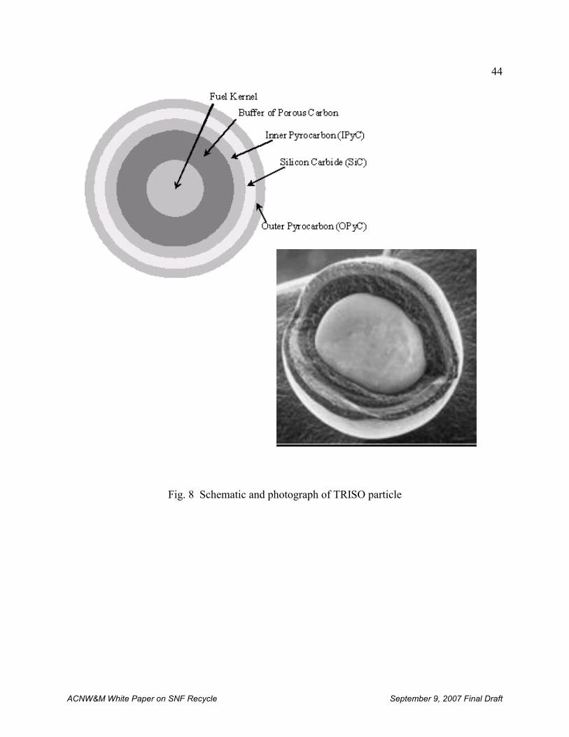
44
ACNW&M White Paper on SNF Recycle September 9, 2007 Final Draft
Fig. 8 Schematic and photograph of TRISO particle
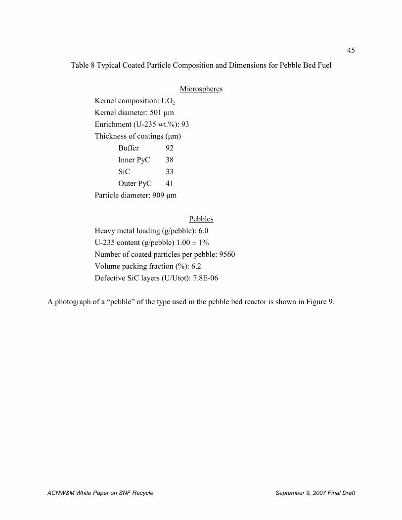
45
ACNW&M White Paper on SNF Recycle September 9, 2007 Final Draft
Table 8 Typical Coated Particle Composition and Dimensions for Pebble Bed Fuel
Microspheres
Kernel composition: UO2
Kernel diameter: 501 μm
Enrichment (U-235 wt.%): 93
Thickness of coatings (μm)
Buffer 92
Inner PyC 38
SiC 33
Outer PyC 41
Particle diameter: 909 μm
Pebbles
Heavy metal loading (g/pebble): 6.0
U-235 content (g/pebble) 1.00 ± 1%
Number of coated particles per pebble: 9560
Volume packing fraction (%): 6.2
Defective SiC layers (U/Utot): 7.8E-06
A photograph of a “pebble” of the type used in the pebble bed reactor is shown in Figure 9.
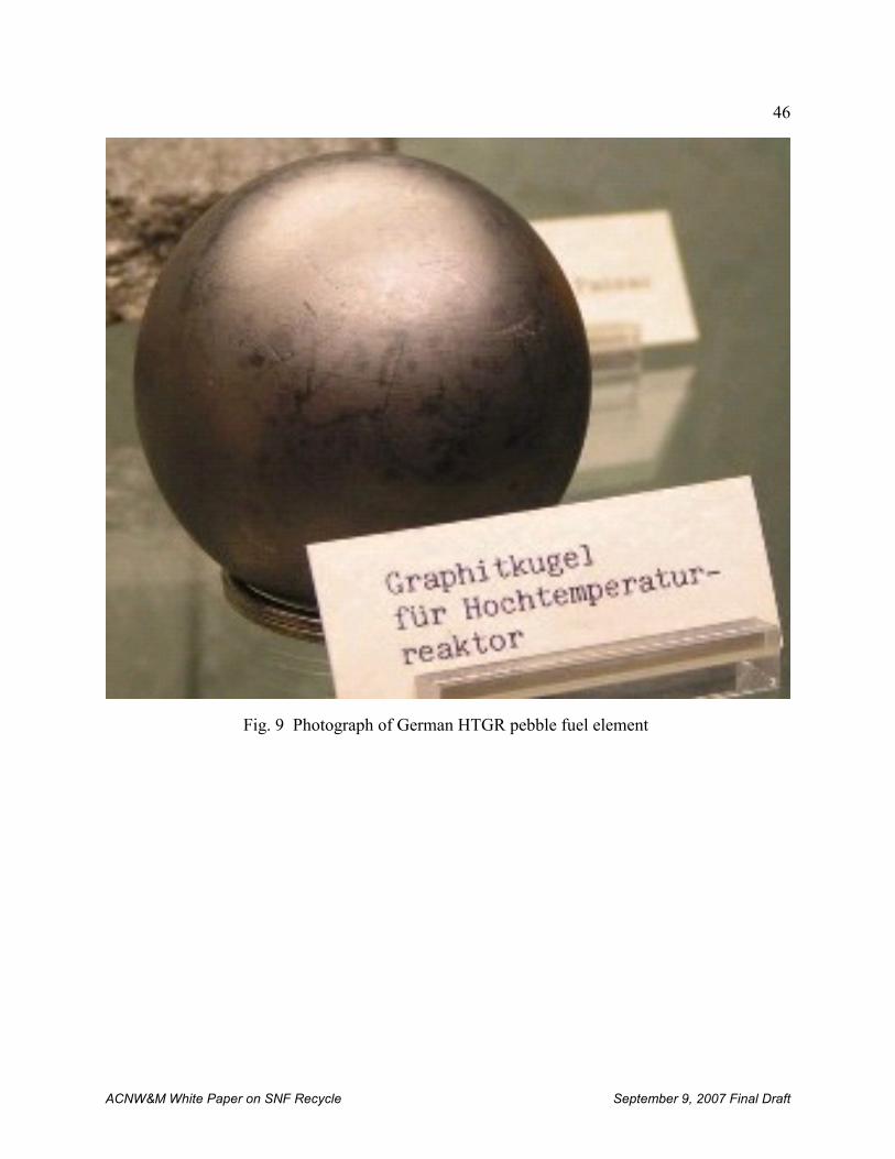
46
ACNW&M White Paper on SNF Recycle September 9, 2007 Final Draft
Fig. 9 Photograph of German HTGR pebble fuel element
47
ACNW&M White Paper on SNF Recycle September 9, 2007 Final Draft
A prismatic fuel assembly of the type developed by General Atomics and used in the commercialFort St. Vrain Power Reactor is shown in Figure 10. These fuel assemblies are 14 inches fromone flat vertical face to the opposing face and about a meter high. Fuel “sticks” of pyrolyzedcarbon containing TRISO fuel particles are inserted into holes in the fuel block. There are alsochannels that go completely through the prismatic block for coolant gas flow. Larger channelsprovide openings into which boron carbide control rods may be inserted.
A major difference in the production of the TRISO coating is that all three layers are coated in a
continuous manner in the German process, whereas in the U.S. process the fuel particles areunloaded from the coater after each coating layer to perform quality control (QC) measurements.The inner pyrocarbon layer in both cases is deposited from a mixture of acetylene, propylene,and argon. The temperature in the U.S. process is somewhat lower than in the German processand the coating gas concentration is different, producing a different microstructure and densityfor the inner pyrocarbon (IPyC) layer. The SiC layer is deposited from a mixture of hydrogenand methyltrichlorosilane at similar coating rates, although the temperature for U.S. coating isabout 150 EC higher than that used in the German process. The outer pyrocarbon layer (OPyC)layer is coated in a manner similar to the IPyC layer. In the U.S. a seal coat and protectivepyrocarbon layer (PPyC) are added. These layers are not counted in determining that the particleis a “TRISO” particle.
The fuel pebble in Germany uses graphite powder and organic binders to produce a powdermatrix that is used to contain the particles and to create the spherical fuel pebble. In the US, athick liquid matrix composed of petroleum pitch, graphite flour and graphite shim mixed withorganic binders is used to make the fuel compact. Both fuel forms are pressed and carbonized athigh temperature (800-900 EC).
Ultra high purity systems and feedstock are used in the manufacture of pebbles in Germany toensure adequate control of impurities. Both fuel forms undergo a final heat treatment, with theU.S. compact heated at 1650 EC and the German pebble at 1800 to 1950 EC in vacuum.
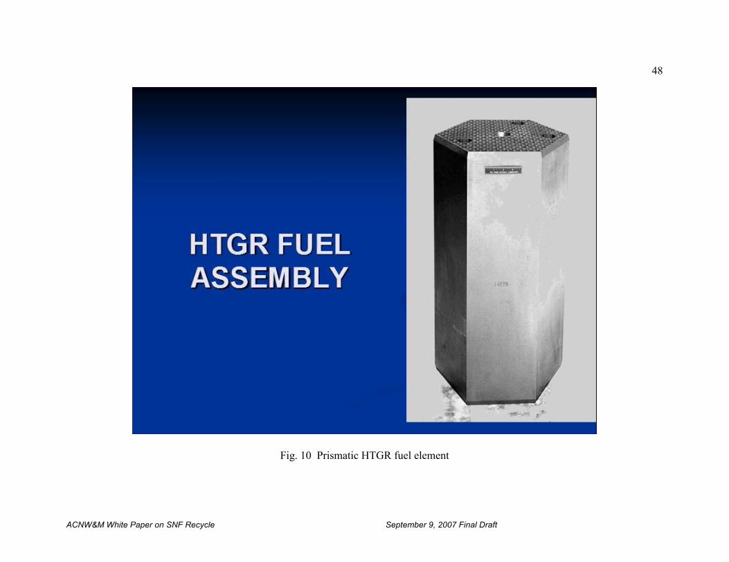
48
ACNW&M White Paper on SNF Recycle September 9, 2007 Final Draft
Fig. 10 Prismatic HTGR fuel element
49
ACNW&M White Paper on SNF Recycle September 9, 2007 Final Draft
IV. RECYCLE FACILITY SITING AND DESIGN
The primary purpose of a reprocessing plant is to chemically separate the fissile content ofirradiated nuclear material from fission products and other actinide elements to recover fissile(235U, 239,240Pu, 233U) and fertile (238U, 232Th) radionuclides. There are five major steps involved inbuilding and operating a reprocessing plant: (1) site selection, (2) plant design, (3) plantconstruction, (4) plant operation, and (5) waste management .
A. Site selection
Siting a reprocessing plant is determined by a large number of considerations. These includeproximity to reactors providing the spent fuel, geology, hydrology, seismology, climatology,flooding potential, topography, demographics, and uses to which the surrounding land is put,e.g., agriculture, industry, and transportation. These considerations are discussed in more detailbelow.
Proximity to reactors producing the spent fuel is important from the point of view of reducingradiation exposure during transportation and increasing the security of shipments but under somecircumstances may not be of paramount importance. This would be true for example if the spentfuel were of foreign origin. In any case, shipment of the spent fuel to the reprocessing plant maybe cause for concern by the public.
Geology of the site is important if radioactive liquid effluents are released because the rate oftransport of radionuclides through the environment is strongly influenced by the nature andconformation of the soil. For example, clay has an affinity for important radioisotopes such as137Cs and rare earths and is likely to be self-healing if fractured, whereas granite has little suchaffinity, and there is no tendency for cracks to heal. Additionally, it is desirable to build areprocessing plant where background radiation is low and not highly variable because it isdifficult to establish an environmental monitoring radioactivity baseline where radiation levelsare high or fluctuate widely. This problem can occur where uranium or thorium levels in the soilare high, leading to high radon levels that may produce large radiation background variationsduring climatic inversions.
Hydrology is very important if radioactive liquid effluents are released because the predominantmechanism for transport of radionuclides is carrying by groundwater. (In the case of an accidenttransport by air can become of great importance, as for example the Chernobyl accident.) Thisaqueous transport pathway may be by the mechanism of carrying dissolved ions of radionuclidesor by carrying colloids or pseudocolloids, e.g., colloids of plutonium or pseudocolloids of iron orclay to which radionuclides are sorbed. The aqueous pathway is the most likely source of non-natural radiation dose to the public through direct ingestion of radionuclides or throughcontamination of agricultural products by irrigation using contaminated groundwater obtainedfrom wells or streams. Hydrology may also be an important consideration in supplying water foruse in the facility if there are no nearby sources of plentiful surface water.
50
ACNW&M White Paper on SNF Recycle September 9, 2007 Final Draft
Seismology has a major impact on licensing plant sites and on plant construction. The plant mustbe sited where it is practical, both economically and physically, to ensure and demonstrate thatits integrity can be retained during a projected earthquake of reasonable probability. Those partsof the reprocessing plant that contain heavy shielding and contain the highest levels ofradioactivity must be capable of withstanding earthquakes with no loss of containment integrity.
Climatology plays a role in plant siting because some areas are prone to seasonal weatherextremes, such as hurricanes, tornadoes, snow and ice storms, and fires in dry weather.
Flooding potential is an important consideration if the site is located in a flood plane, near riversor streams, or is in the path of seasonal snow-melt runoff or dam failure.
Topography plays a role because the cost of plant construction may be high if grades are toosteep, too much soil removal is required, or water drainage is inadequate and poses constructionand subsequent operational problems.
Demographics play a major role in gaining public acceptance of a site. Whenever practicable itis desirable to site a reprocessing plant distant from large population centers. This considerationmay be at odds with locating the reprocessing plant near reactors where transportation problemsare minimized and is an example of often conflicting siting considerations.
Agriculture and Industry in the neighborhood of a potential plant site can be of considerableimportance. The presence of a facility that handles large amounts of radioactivity can beclaimed to diminish the value of the crops, the land, or the products produced. Additionally,release of radioactivity and concomitant contamination of expensive crops or industrial buildingsand machinery can lead to very large financial obligations.
Transportation activities, such as commercial air, rail, or truck traffic need to be considered. This applies both to the transport of radioactive materials and to ordinary commercial traffic. Heavily traveled highways such as interstates in the immediate vicinity of the plant may causeconcern to the public or the Departments of Transportation, both federal and local. Intermodalspent fuel transport, including use of navigable waterways, may cause concern with sportsmen aswell as health departments if the waterways are the source of drinking water. Thesetransportation issues are especially nettlesome because of the need to balance negative publicperception with the desirability for the plant to be reasonably close to the source of the spentfuel.
B. Design and Construction
A typical spent fuel reprocessing facility is designed and constructed to minimize the release ofradioactive materials within and outside the facility both during routine operation and underunusual or accident conditions. Specifically, the current 10 CFR Part 20 Subpart E §1406“Minimization of contamination” states the following: “Applicants for licenses, other thanrenewals, after August 20, 1997, shall describe in the application how facility design andprocedures for operation will minimize, to the extent practicable, contamination of the facility
51
ACNW&M White Paper on SNF Recycle September 9, 2007 Final Draft
and the environment, facilitate eventual decommissioning, and minimize, to the extentpracticable, the generation of radioactive waste.” At least two physical barriers (frequently morethan two) contain the radioactive materials within the facility during operation. These barriersare typically the process equipment (vessels, pipes, etc.) and the building around the processingequipment. In most cases, the building itself provides two barriers – the hot cell or room wherethe process equipment is located and the outer building shell.
The discussion that follows is based for the most part on the BNFP. Significant advances havebeen made in the design and operation of reprocessing plants as a result of internationalexperience.
1. Design
Historically, recycle plants have consisted of four major processing facilities plus a fuelreceiving and storage area:
(1) The Separations Facility, in which the spent fuel assemblies are processed to recoveruranium and plutonium as nitrate solutions and where the bulk of radioactive by-product wastesare separated as a concentrated nitrate solution of HLW.
(2) Uranium Hexaflouride Facility in which the recovered purified uranyl nitrate solution isconverted to UF6 suitable as a feed material for isotopic re-enrichment if desired.
(3) Plutonium Product Facility in which the recovered plutonium nitrate solution is converted toPuO2, suitable for use in the production of mixed oxide fuel (MOX).
(4) Waste Management Facilities for the handling, stabilization, packaging, assaying, inspection,and interim storage of waste prior to shipment to a disposal facility appropriate for each type ofwaste. It should be noted that the current 10 CFR Part 20.1406 “Minimization of contamination”states the following: “Applicants for licenses after August 20, 1997, shall describe in theapplication how the facility design and procedures for operations will minimize, to the extentpracticable, contamination of the facility and the environment, facilitate eventualdecommissioning, and minimize, to the extent practicable, the generation of waste.”
NRC’s Office of Nuclear Regulatory Research (RES) is developing a regulatory guide toimplement 10 CFR Part 20.1406 to facilitate decommissioning of nuclear facilities licensed afterAugust 20, 2007. The goal of this guide is to ensure throughout the life of he facility that designand operating procedures minimize the amount of residual radioactivity that will requireremediation at the time of decommissioning. Reprocessing plants will be included under thisguidance.
The actual design of these major facilities will be directly related to the regulations effective atthe time of licensing and the desired/required form of both the fissile as well as the wastematerial discharged. Proliferation and safeguards are of national and international concern when
52
ACNW&M White Paper on SNF Recycle September 9, 2007 Final Draft
considering the construction of a recycling plant, as are attacks by terrorists. Beyond theseoverriding considerations there are very important practical matters that must be taken intoaccount in the design, construction and operation of a plant.
It is necessary to optimize the plant configuration for reprocessing to minimize the overallfacility capital and operating costs. This is done by considering the interplay of a large numberof factors. Initially, it must be decided if the plant is to be designed with a single, multiple step,process line or whether it will have parallel process lines. If the plant is to process a variety offuel types or a very large throughput is required then parallel lines will facilitate processingdissimilar fuel types, allow maintenance of one line when the other line is in operation, or allowpractical equipment sizes while achieving high throughput.
Another aspect of plant optimization concerns approaches for waste treatment (e.g.,concentration of liquid wastes by evaporation and compaction or melting of spent fuel claddinghulls and other hardware), and its storage and disposal. Design optimization also addressesradiation protection of workers through use of the minimum shielding thickness consistent withmeeting ALARA and radiation dose and radioactivity confinement requirements; appropriateselection of the processes carried out in the plant; and careful choice of the equipment used tocarry out those processes. Simple, reliable equipment, continuous operation where possible, andease of remote removal and replacement of equipment all contribute to minimizing capital andoperating costs. In addition to being able to achieve the desired throughput, each equipmentpiece in the high radiation areas of the plant must be capable of being replaced remotely or havea very low probability of failure (e.g., no moving parts, exceedingly corrosion resistant, becritically safe, be matched to the characteristics of the fuel assemblies to be reprocessed, andchosen insofar as possible to be of standard sizes. Inoperability of a reprocessing plant is likelyto result from structural failure of equipment or piping in an inaccessible area as a result ofcorrosion or mechanical failure, or failure of some part of the separations process.
There is an optimum point in design of criticality features. For example, there is a tradeoffbetween having many small, critically safe process lines that offer protection for dissolver feedthrough geometry and having fewer, larger lines that achieve criticality safety through othermeans such as neutron poisons. The choice is made largely on the basis of cost, with the largenumber of smaller lines being more costly.
Some general guidelines are useful to keep in mind in plant design: It is desirable for radiationprotection and ease of operation to put equipment for receiving the spent fuel, spent fuel pooland HLW storage, the fuel segment storage, and the reprocessing product storage in separatecells interconnected through transfer channels to the processing area. Ventilation and wastetreatment capabilities may be provided separately for each segment. However, some facilitiessuch as those used in maintenance may be shared. Avoiding inaccessible equipment or piping isalso very important.
One additional area that has proved troublesome is managing the complexity and cost associatedwith different fuel types and sizes. Variable fuel design require different handling equipment forcasks and fuel assemblies, and interim storage racks or casks
.
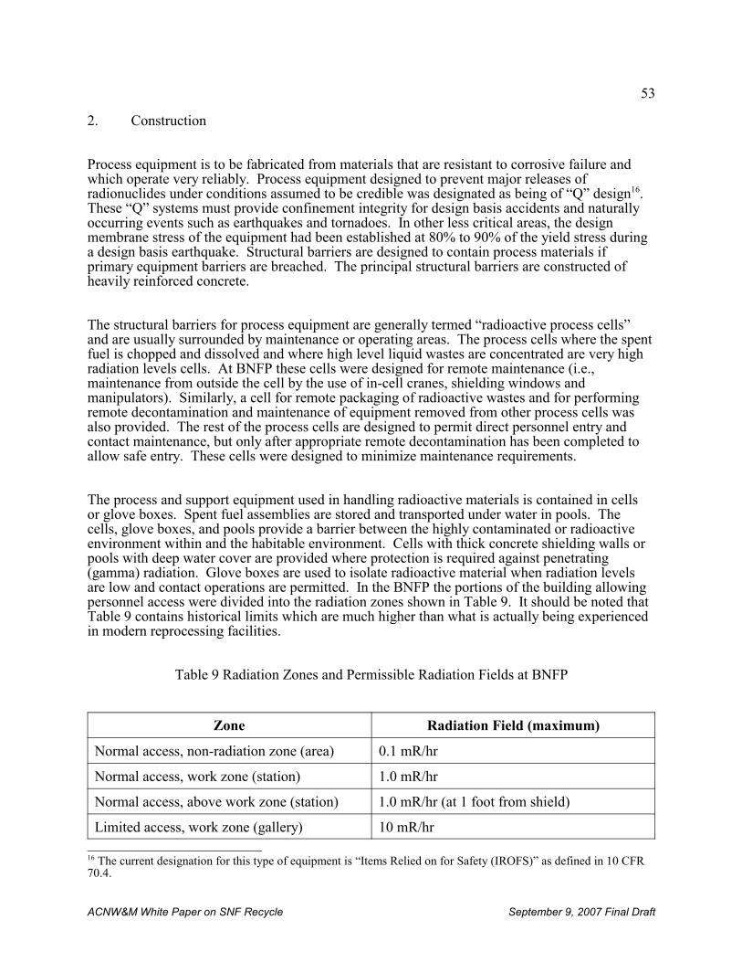
53
16 The current designation for this type of equipment is “Items Relied on for Safety (IROFS)” as defined in 10 CFR70.4.
ACNW&M White Paper on SNF Recycle September 9, 2007 Final Draft
2. Construction
Process equipment is to be fabricated from materials that are resistant to corrosive failure andwhich operate very reliably. Process equipment designed to prevent major releases ofradionuclides under conditions assumed to be credible was designated as being of “Q” design16. These “Q” systems must provide confinement integrity for design basis accidents and naturallyoccurring events such as earthquakes and tornadoes. In other less critical areas, the designmembrane stress of the equipment had been established at 80% to 90% of the yield stress duringa design basis earthquake. Structural barriers are designed to contain process materials ifprimary equipment barriers are breached. The principal structural barriers are constructed ofheavily reinforced concrete.
The structural barriers for process equipment are generally termed “radioactive process cells”and are usually surrounded by maintenance or operating areas. The process cells where the spentfuel is chopped and dissolved and where high level liquid wastes are concentrated are very highradiation levels cells. At BNFP these cells were designed for remote maintenance (i.e.,maintenance from outside the cell by the use of in-cell cranes, shielding windows andmanipulators). Similarly, a cell for remote packaging of radioactive wastes and for performingremote decontamination and maintenance of equipment removed from other process cells wasalso provided. The rest of the process cells are designed to permit direct personnel entry andcontact maintenance, but only after appropriate remote decontamination has been completed toallow safe entry. These cells were designed to minimize maintenance requirements.
The process and support equipment used in handling radioactive materials is contained in cellsor glove boxes. Spent fuel assemblies are stored and transported under water in pools. Thecells, glove boxes, and pools provide a barrier between the highly contaminated or radioactiveenvironment within and the habitable environment. Cells with thick concrete shielding walls orpools with deep water cover are provided where protection is required against penetrating(gamma) radiation. Glove boxes are used to isolate radioactive material when radiation levelsare low and contact operations are permitted. In the BNFP the portions of the building allowingpersonnel access were divided into the radiation zones shown in Table 9. It should be noted thatTable 9 contains historical limits which are much higher than what is actually being experiencedin modern reprocessing facilities.
Table 9 Radiation Zones and Permissible Radiation Fields at BNFP
Zone Radiation Field (maximum)
Normal access, non-radiation zone (area) 0.1 mR/hr
Normal access, work zone (station) 1.0 mR/hr
Normal access, above work zone (station) 1.0 mR/hr (at 1 foot from shield)
Limited access, work zone (gallery) 10 mR/hr
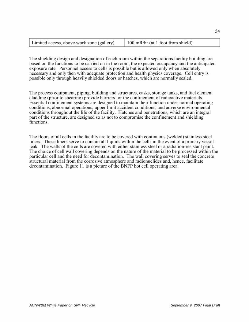
54
ACNW&M White Paper on SNF Recycle September 9, 2007 Final Draft
Limited access, above work zone (gallery) 100 mR/hr (at 1 foot from shield)
The shielding design and designation of each room within the separations facility building arebased on the functions to be carried on in the room, the expected occupancy and the anticipatedexposure rate. Personnel access to cells is possible but is allowed only when absolutelynecessary and only then with adequate protection and health physics coverage. Cell entry ispossible only through heavily shielded doors or hatches, which are normally sealed.
The process equipment, piping, building and structures, casks, storage tanks, and fuel elementcladding (prior to shearing) provide barriers for the confinement of radioactive materials. Essential confinement systems are designed to maintain their function under normal operatingconditions, abnormal operations, upper limit accident conditions, and adverse environmentalconditions throughout the life of the facility. Hatches and penetrations, which are an integralpart of the structure, are designed so as not to compromise the confinement and shieldingfunctions.
The floors of all cells in the facility are to be covered with continuous (welded) stainless steelliners. These liners serve to contain all liquids within the cells in the event of a primary vesselleak. The walls of the cells are covered with either stainless steel or a radiation-resistant paint. The choice of cell wall covering depends on the nature of the material to be processed within theparticular cell and the need for decontamination. The wall covering serves to seal the concretestructural material from the corrosive atmosphere and radionuclides and, hence, facilitatedecontamination. Figure 11 is a picture of the BNFP hot cell operating area.
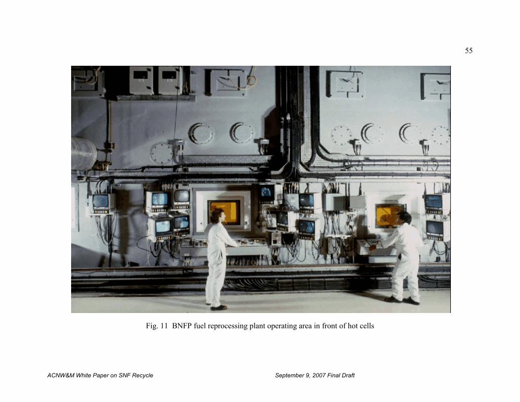
55
ACNW&M White Paper on SNF Recycle September 9, 2007 Final Draft
Fig. 11 BNFP fuel reprocessing plant operating area in front of hot cells
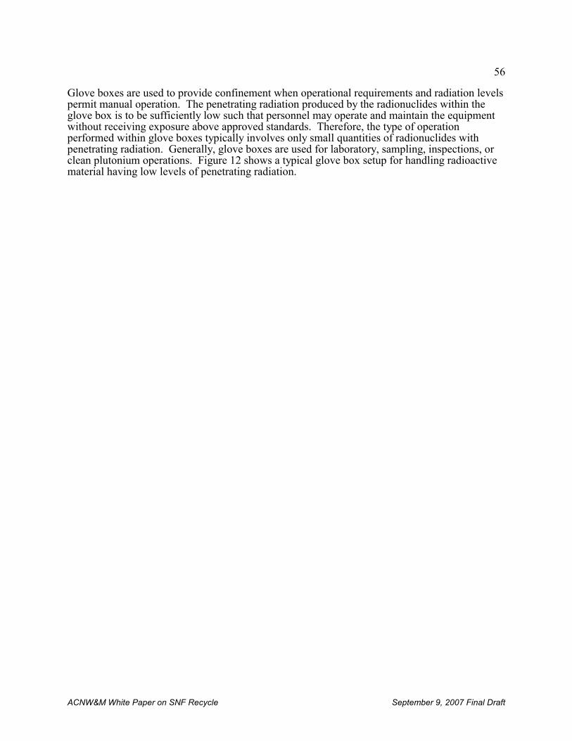
56
ACNW&M White Paper on SNF Recycle September 9, 2007 Final Draft
Glove boxes are used to provide confinement when operational requirements and radiation levelspermit manual operation. The penetrating radiation produced by the radionuclides within theglove box is to be sufficiently low such that personnel may operate and maintain the equipmentwithout receiving exposure above approved standards. Therefore, the type of operationperformed within glove boxes typically involves only small quantities of radionuclides withpenetrating radiation. Generally, glove boxes are used for laboratory, sampling, inspections, orclean plutonium operations. Figure 12 shows a typical glove box setup for handling radioactivematerial having low levels of penetrating radiation.
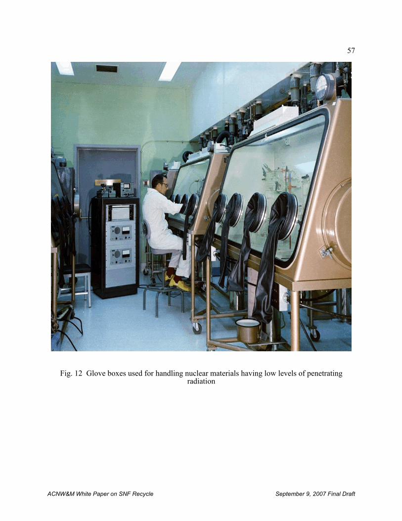
57
ACNW&M White Paper on SNF Recycle September 9, 2007 Final Draft
Fig. 12 Glove boxes used for handling nuclear materials having low levels of penetratingradiation
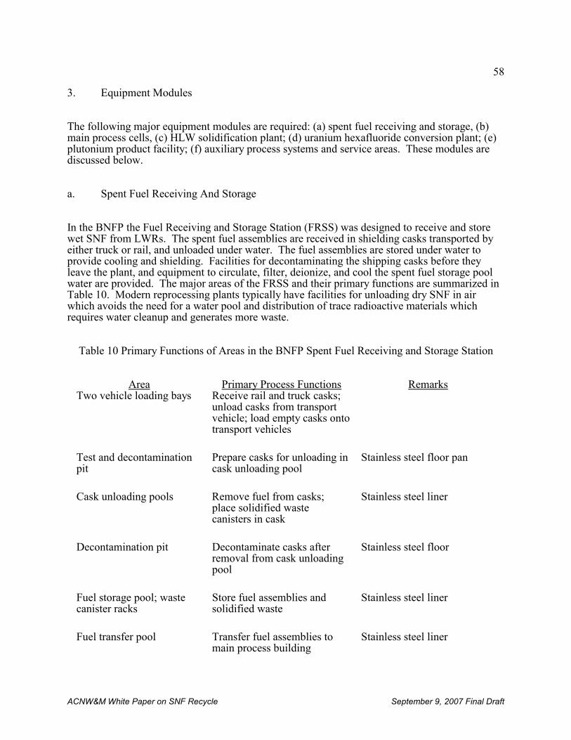
58
ACNW&M White Paper on SNF Recycle September 9, 2007 Final Draft
3. Equipment Modules
The following major equipment modules are required: (a) spent fuel receiving and storage, (b)main process cells, (c) HLW solidification plant; (d) uranium hexafluoride conversion plant; (e)plutonium product facility; (f) auxiliary process systems and service areas. These modules arediscussed below.
a. Spent Fuel Receiving And Storage
In the BNFP the Fuel Receiving and Storage Station (FRSS) was designed to receive and storewet SNF from LWRs. The spent fuel assemblies are received in shielding casks transported byeither truck or rail, and unloaded under water. The fuel assemblies are stored under water toprovide cooling and shielding. Facilities for decontaminating the shipping casks before theyleave the plant, and equipment to circulate, filter, deionize, and cool the spent fuel storage poolwater are provided. The major areas of the FRSS and their primary functions are summarized inTable 10. Modern reprocessing plants typically have facilities for unloading dry SNF in airwhich avoids the need for a water pool and distribution of trace radioactive materials whichrequires water cleanup and generates more waste.
Table 10 Primary Functions of Areas in the BNFP Spent Fuel Receiving and Storage Station
Area Primary Process Functions RemarksTwo vehicle loading bays Receive rail and truck casks;
unload casks from transportvehicle; load empty casks ontotransport vehicles
Test and decontaminationpit
Prepare casks for unloading incask unloading pool
Stainless steel floor pan
Cask unloading pools Remove fuel from casks;place solidified wastecanisters in cask
Stainless steel liner
Decontamination pit Decontaminate casks afterremoval from cask unloadingpool
Stainless steel floor
Fuel storage pool; wastecanister racks
Store fuel assemblies andsolidified waste
Stainless steel liner
Fuel transfer pool Transfer fuel assemblies tomain process building
Stainless steel liner
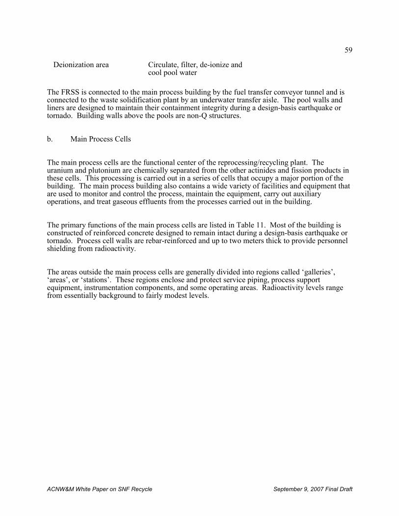
59
ACNW&M White Paper on SNF Recycle September 9, 2007 Final Draft
Deionization area Circulate, filter, de-ionize andcool pool water
The FRSS is connected to the main process building by the fuel transfer conveyor tunnel and isconnected to the waste solidification plant by an underwater transfer aisle. The pool walls andliners are designed to maintain their containment integrity during a design-basis earthquake ortornado. Building walls above the pools are non-Q structures.
b. Main Process Cells
The main process cells are the functional center of the reprocessing/recycling plant. Theuranium and plutonium are chemically separated from the other actinides and fission products inthese cells. This processing is carried out in a series of cells that occupy a major portion of thebuilding. The main process building also contains a wide variety of facilities and equipment thatare used to monitor and control the process, maintain the equipment, carry out auxiliaryoperations, and treat gaseous effluents from the processes carried out in the building.
The primary functions of the main process cells are listed in Table 11. Most of the building isconstructed of reinforced concrete designed to remain intact during a design-basis earthquake ortornado. Process cell walls are rebar-reinforced and up to two meters thick to provide personnelshielding from radioactivity.
The areas outside the main process cells are generally divided into regions called ‘galleries’,‘areas’, or ‘stations’. These regions enclose and protect service piping, process supportequipment, instrumentation components, and some operating areas. Radioactivity levels rangefrom essentially background to fairly modest levels.
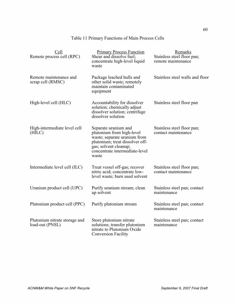
60
ACNW&M White Paper on SNF Recycle September 9, 2007 Final Draft
Table 11 Primary Functions of Main Process Cells
Cell Primary Process Function RemarksRemote process cell (RPC) Shear and dissolve fuel;
concentrate high-level liquidwaste
Stainless steel floor pan;remote maintenance
Remote maintenance andscrap cell (RMSC)
Package leached hulls andother solid waste; remotelymaintain contaminatedequipment
Stainless steel walls and floor
High-level cell (HLC) Accountability for dissolversolution; chemically adjustdissolver solution; centrifugedissolver solution
Stainless steel floor pan
High-intermediate level cell(HILC)
Separate uranium andplutonium from high-levelwaste; separate uranium fromplutonium; treat dissolver off-gas; solvent cleanup;concentrate intermediate-levelwaste
Stainless steel floor pan;contact maintenance
Intermediate level cell (ILC) Treat vessel off-gas; recovernitric acid; concentrate low-level waste; burn used solvent
Stainless steel floor pan;contact maintenance
Uranium product cell (UPC) Purify uranium stream; cleanup solvent
Stainless steel pan; contactmaintenance
Plutonium product cell (PPC) Purify plutonium stream Stainless steel pan; contactmaintenance
Plutonium nitrate storage andload-out (PNSL)
Store plutonium nitratesolutions; transfer plutoniumnitrate to Plutonium OxideConversion Facility
Stainless steel pan; contactmaintenance
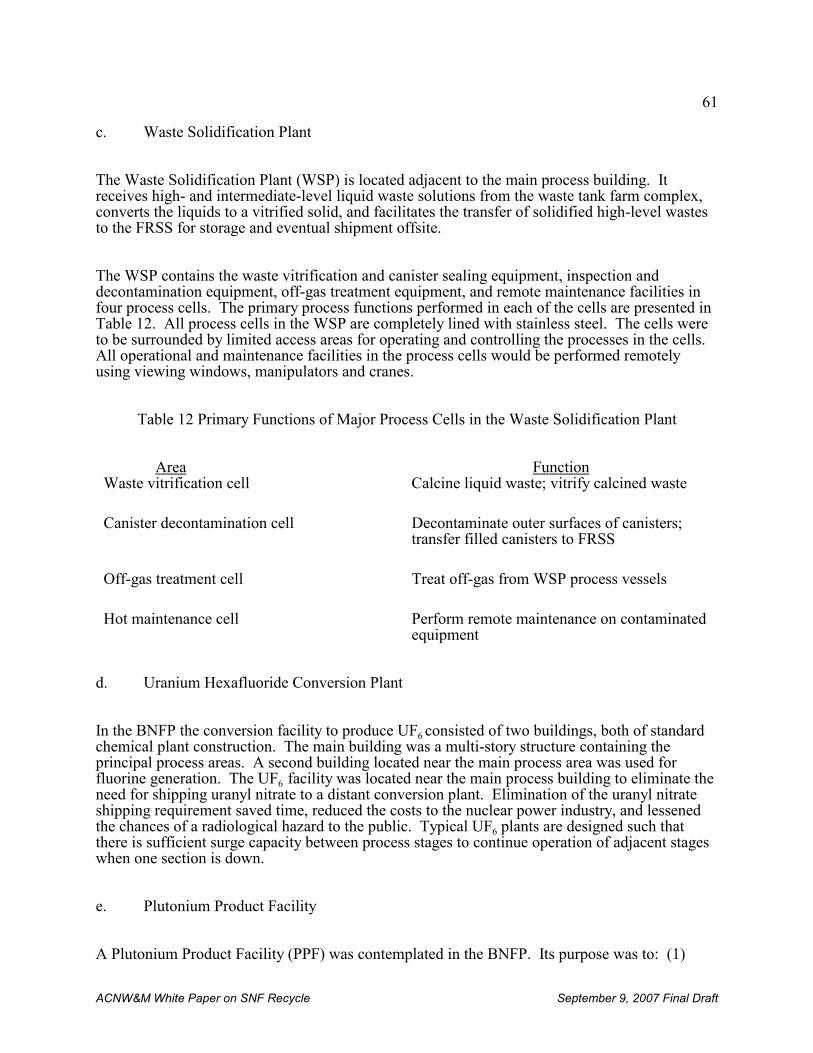
61
ACNW&M White Paper on SNF Recycle September 9, 2007 Final Draft
c. Waste Solidification Plant
The Waste Solidification Plant (WSP) is located adjacent to the main process building. Itreceives high- and intermediate-level liquid waste solutions from the waste tank farm complex,converts the liquids to a vitrified solid, and facilitates the transfer of solidified high-level wastesto the FRSS for storage and eventual shipment offsite.
The WSP contains the waste vitrification and canister sealing equipment, inspection anddecontamination equipment, off-gas treatment equipment, and remote maintenance facilities infour process cells. The primary process functions performed in each of the cells are presented inTable 12. All process cells in the WSP are completely lined with stainless steel. The cells wereto be surrounded by limited access areas for operating and controlling the processes in the cells. All operational and maintenance facilities in the process cells would be performed remotelyusing viewing windows, manipulators and cranes.
Table 12 Primary Functions of Major Process Cells in the Waste Solidification Plant
Area FunctionWaste vitrification cell Calcine liquid waste; vitrify calcined waste
Canister decontamination cell Decontaminate outer surfaces of canisters;transfer filled canisters to FRSS
Off-gas treatment cell Treat off-gas from WSP process vessels
Hot maintenance cell Perform remote maintenance on contaminatedequipment
d. Uranium Hexafluoride Conversion Plant
In the BNFP the conversion facility to produce UF6 consisted of two buildings, both of standardchemical plant construction. The main building was a multi-story structure containing theprincipal process areas. A second building located near the main process area was used forfluorine generation. The UF6 facility was located near the main process building to eliminate theneed for shipping uranyl nitrate to a distant conversion plant. Elimination of the uranyl nitrateshipping requirement saved time, reduced the costs to the nuclear power industry, and lessenedthe chances of a radiological hazard to the public. Typical UF6 plants are designed such thatthere is sufficient surge capacity between process stages to continue operation of adjacent stageswhen one section is down.
e. Plutonium Product Facility
A Plutonium Product Facility (PPF) was contemplated in the BNFP. Its purpose was to: (1)
62
ACNW&M White Paper on SNF Recycle September 9, 2007 Final Draft
convert aqueous plutonium nitrate solutions to plutonium oxide, and (2) provide storage forplutonium oxide. The PPF process facilities were to be located in a separate buildingimmediately adjacent to the Main Process Building.
The Plutonium Product Facility was to have a nominal design capacity of 100 kg of plutoniumproduct (as plutonium dioxide) per day with an on-stream time of 250 days per year to give anannual conversion capacity of 25,000 kg of plutonium (1134 g of PuO2 contains 1,000g ofplutonium). This capacity would be divided between two identical production lines, each with acapacity of 50 kg per day. This design basis was selected to allow a 1,500 MTU/yearreprocessing/recycling facility to process mixed-oxide feed material for fuels having plutoniumcontents higher than LWR recycled fuels. Although the design capacity was 25,000 kg ofplutonium per year, it could be operated at a lower capacity.
Most of the operations and maintenance in the facility were to be carried out in glove boxes. Leaded gloves were planned to be used to protect against low-level gamma radiation, andrelatively thin concrete and other hydrogenous shields would be used to protect against theneutron radiation from the 238Pu [from (α, n) radiation produced when high-energy alphaparticles strike low-atomic number elements].
f. Auxiliary Process Systems and Service Areas
The Auxiliary Process Systems and Service Areas provide necessary services to the mainprocess functions of the Main Process Building. The major areas are described below.
i. Ventilation System
The ventilation system consists primarily of supply and exhaust subsystems. The ventilationsystem was designed to provide once-through airflow by pressure controls from non-contaminated areas through potentially contaminated or low-contaminated areas to highlycontaminated areas (i.e., process cells), then to treatment systems before being pumped byblowers out the stack. Three blowers were to provide exhaust for the main ventilation system. Each blower was to be capable of supplying fifty (50%) percent of the required capacity and wasto be connected to emergency power sources.
Exhaust gases from the radioactive processing cells were to pass through at least two stages ofhigh-efficiency particulate air (HEPA) filters. Off-gases from areas with high plutoniumconcentrations were to pass through three stages of HEPA filters. These extra stages of filtrationwere designed to provide for a minimum of one stage of filtration in the event of failure of theupstream filters by mechanisms such as fire. Exhaust gases from the main process and buildingventilation systems exited through the main stack (100 meters high). Non-condensed gases fromthe concentrator vented through the service concentrator stack (30.5 meters high). The chemicalmakeup and addition tank vented through the chemical off-gas stack (29 meters high).
A major feature of the ventilation system was the ventilation filter station. This housed the
63
17 In contrast to the ventilation system planned for BNFP, experience in existing large commercial reprocessingfacilities has shown the need for wet scrubbers, condensers, mist eliminators, HEPA filters, etc. to meet effluentdischarge limits.
18 Halon is a liquefied, compressed halogenated hydrocarbon gas that stops the spread of fire by physicallypreventing (suffocating) combustion. Although the production of Halon in the U.S. ceased on January 1, 1994 underthe Clean Air Act, it is still legal to purchase and use recycled Halon and Halon fire extinguishers.
ACNW&M White Paper on SNF Recycle September 9, 2007 Final Draft
primary supply and exhaust blowers and the final stage of HEPA filters through which theexhaust air passed before exhausting through the 100 meter stack17. In this late twentieth centurydesign, a cryogenic krypton capture and recovery system was planned to be incorporated, butneither a krypton recovery system nor a system for capture of tritium and 14C was being builtwhen construction ceased.
ii. Electrical Power
Normal electrical power was provided to the facility from a commercial substation by twotransformers, each feeding a 2,000 amp main breaker. The main breakers distributed powerthrough twelve 120 amp feeder breakers.
The emergency electric power system was designed to handle essential electrical loads inemergency situations. Emergency power was supplied by two independent diesel engine-drivengenerators. Each generator had a 2,200 kw continuous rating. An emergency battery supply wasprovided for instrumentation in the main control and the waste tank equipment gallery area.
iii. Fire Protection System
Fire detection and protection systems at the facility were designed to provide early warning andrapid control of fire. Automatic fire detection devices and audible alarms were installed in allareas of the facility. The process cells had dual detection systems. The remotely maintainedprocess cells used manually operated non-combustible purges and water spray mist systems. The contact-maintained cells were served by automatically operated Halon18 systems. The filterstations were designed with automatic mist suppression systems, and the FRSS had manuallyoperated fire hoses. Most other areas used a manually operated water sprinkler system.
iv. Hot and Cold Laboratory Area
The laboratories provided analytical services for all non-radioactive and most radioactiveprocess samples. At the BNFP, the laboratory building was a two-story complex adjacent to themain process building. It was composed of thirteen individual laboratories equipped to providespecific types of analysis or services. Radioactive materials in these laboratories were handledin glove boxes. The sample and analytical cells are in a shielded facility designed to facilitateradiochemical analyses of samples from the more highly radioactive portions of the process. The cells provide a shielded area for remote sampling and analysis of these materials, and forpreparation of samples to be analyzed in the plant analytical laboratories. Operation is throughthe use of either shielded cells with viewing windows and manipulators or glove boxes.
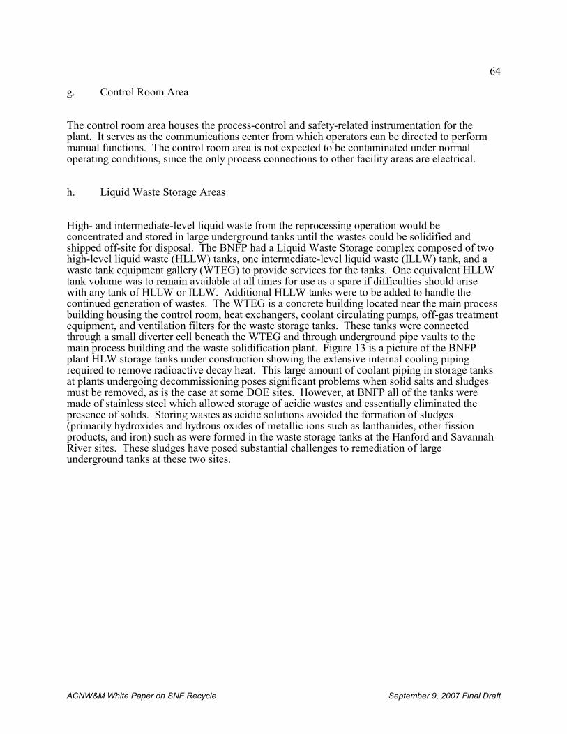
64
ACNW&M White Paper on SNF Recycle September 9, 2007 Final Draft
g. Control Room Area
The control room area houses the process-control and safety-related instrumentation for theplant. It serves as the communications center from which operators can be directed to performmanual functions. The control room area is not expected to be contaminated under normaloperating conditions, since the only process connections to other facility areas are electrical.
h. Liquid Waste Storage Areas
High- and intermediate-level liquid waste from the reprocessing operation would beconcentrated and stored in large underground tanks until the wastes could be solidified andshipped off-site for disposal. The BNFP had a Liquid Waste Storage complex composed of twohigh-level liquid waste (HLLW) tanks, one intermediate-level liquid waste (ILLW) tank, and awaste tank equipment gallery (WTEG) to provide services for the tanks. One equivalent HLLWtank volume was to remain available at all times for use as a spare if difficulties should arisewith any tank of HLLW or ILLW. Additional HLLW tanks were to be added to handle thecontinued generation of wastes. The WTEG is a concrete building located near the main processbuilding housing the control room, heat exchangers, coolant circulating pumps, off-gas treatmentequipment, and ventilation filters for the waste storage tanks. These tanks were connectedthrough a small diverter cell beneath the WTEG and through underground pipe vaults to themain process building and the waste solidification plant. Figure 13 is a picture of the BNFPplant HLW storage tanks under construction showing the extensive internal cooling pipingrequired to remove radioactive decay heat. This large amount of coolant piping in storage tanksat plants undergoing decommissioning poses significant problems when solid salts and sludgesmust be removed, as is the case at some DOE sites. However, at BNFP all of the tanks weremade of stainless steel which allowed storage of acidic wastes and essentially eliminated thepresence of solids. Storing wastes as acidic solutions avoided the formation of sludges(primarily hydroxides and hydrous oxides of metallic ions such as lanthanides, other fissionproducts, and iron) such as were formed in the waste storage tanks at the Hanford and SavannahRiver sites. These sludges have posed substantial challenges to remediation of largeunderground tanks at these two sites.
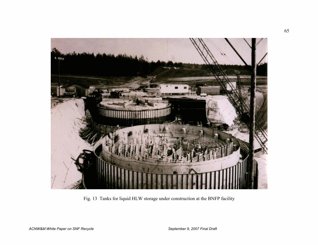
65
ACNW&M White Paper on SNF Recycle September 9, 2007 Final Draft
Fig. 13 Tanks for liquid HLW storage under construction at the BNFP facility
66
19 NRC does not have a category of waste called “low-level general process trash. The term was used by BNFP as adescriptive identifier of a type of radioactive waste rather than as formal waste classification.
ACNW&M White Paper on SNF Recycle September 9, 2007 Final Draft
i. Solid Waste Storage
The BNFP design included a solid waste storage area of approximately twenty (20) acres -- anarea deemed sufficient to store the solid waste generated during the first three years of operation. The solid wastes to be stored in this area were divided into three major categories: (1) spent fuelcladding hulls and hardware; (2) high-level general process trash (HLGPT); and (3) low-levelgeneral process trash (LLGPT)19. Hulls and HLGPT were to be stored in caissons mounted in anengineered berm or in concrete vaults. The LLGPT would be stored in earth-covered cargocontainers. In modern reprocessing plants the required waste storage volume per unit of SNFprocesses is likely to be less because of improved operational practices.
4. Criticality Control Methods
Whenever enriched uranium or plutonium are present criticality control becomes an important consideration. The method used to control criticality depends on the physical and chemicalnature of the fissile material, its mass and purity, and its geometry. Several control methodshave been employed whose use depends on the above factors.
a. Physical form control
It is important to know if the physical form is such that fissile material can be compacted toincrease its density. It is also very important to know what the chemical composition is. If it ischemically combined with elements that absorb neutrons it is less likely to present a criticalityrisk.
b. Mass control
For criticality to occur it is essential that the amount of fissile material equal or exceed theminimum critical mass. A common approach to preventing criticality is limiting the allowableamount of fissile material in any one location to less than a critical mass.
c. Composition control
Certain chemicals mixed with the fissile material can prevent criticality by absorbing neutrons. Elements with isotopes having large neutron absorption cross sections such as boron, cadmium,or gadolinium, are commonly added to fissile materials. Usually these elements are in a formpermitting their easy removal when desired.
d. Geometry control
67
ACNW&M White Paper on SNF Recycle September 9, 2007 Final Draft
Vessels having geometries that allow for loss of neutrons through their surfaces in amounts suchthat a chain reaction cannot be sustained in the vessels are universally used. The vessels may beof many differing configurations, but cylindrical or flat “slab” configurations are common. Typically one dimension such as diameter in the case of cylinders or thickness in the case ofslabs is limited to the order of 13 cm. Another geometry that has been used is annular tanks,with neutron poisons in the annulus.
C. Du Pont Reprocessing Studies
After many years of operating the DOE Savannah River Site reprocessing plant the du PontCompany carried out and supported research and development by others of a conceptual designfor what would be an NRC licensed fuel recycle complex based on du Pont’s reprocessingexperience and lessons learned from that experience and the experience of others. The designstudies were completed and reports issued in November 1978 [Behran, 2000]. This facilitydesign was not considered in White House reviews of reprocessing during the Ford, Carter, orReagan administrations. Many, but not all, of the special features listed below are incorporatedin reprocessing plants overseas.
Special features of the du Pont facility design included:
! Canyon structures for containing process equipment that could be installed, maintainedand replaced remotely using overhead cranes,
! Use of the best technology available, including centrifugal contactors for the first cycleof solvent extraction, and storage of solutions between process steps,
! Product recoveries greater than 99.8 %,
! Reprocessing one-year cooled spent fuel,
! Personnel access to operating areas, with close control of entry and exit,
! Vitrification of high-level wastes for ultimate storage,
! Flexibility to allow changes, additions, or upgrades of equipment, flowsheets,instruments, etc.,
! No accumulation of separated plutonium except in secure surge storage betweenreprocessing and fuel fabrication
! Tritium and krypton capture in addition to iodine,
! Sand filters,
! Opportunities for lowering cost through research and development as a result of longercooling time before reprocessing.
D. Operator Licensing and Training
The operation of a reprocessing/recycling facility entails all of the operational skills and safetyrequirements associated with a reasonably complex chemical processing plant overlain with the
68
ACNW&M White Paper on SNF Recycle September 9, 2007 Final Draft
radiation safety, security and safeguards requirements of a significant radioactive nuclearfacility. However, other than as noted in the preceding sections of this report, there is littlecurrent commercial experience remaining in the NRC regulated world and that which does existresides mostly in people who have retired. Therefore, the training and qualification of theoperating staff takes on major significance in the absence of the ability to rely on a pool of fullytrained, experienced, and licensed personnel.
In the past, the general criteria was for operators, technicians and supervisors to have received atleast a two year certificate from an established technical school. Applicants with thisbackground normally have sufficient understanding of the physical, chemical, and engineeringtechnologies to adequately undertake the necessary specific plant training.
The importance of qualified operators to the safety of a reprocessing plant can hardly be overemphasized. The contents of an application for licensing individuals who manipulate thecontrols of a properly licensed facility (at the time of BNFP) are set forth in 10 CFR Part 55,Subpart D, §55.31.
1. Experience at NFS
Experience gained from the past licensing of reprocessing plant operators at other commercialreprocessing plants may be of some benefit to this study. This historical experience may be usedas an indicator of the validity of the requirement for training and the evolution of trainingprograms over the years, as well as the possible direction of future training efforts.
During the planning stages of NFS, their management and the regulatory staff of the U.S.Atomic Energy Commission established four major operator categories:
(1) manipulator operators,
(2) chemical operators,
(3) control room operators, and
(4) senior operators.
These categories were similar, in most respects, to those presented in the USAEC LicensingGuide, which was used at that time for nuclear reactor operators.
The results of the original examining program in 1966 were disappointing. Of the total numberof senior operator applicants taking the examination, seventy-eight (78%) percent weresuccessful in obtaining licenses; however, only fifty-nine (59%) percent of the chemicaloperations personnel applying for licenses were successful. Only nine (9%) percent wereinitially awarded licenses. Some of the reasons for the excessive failure rate were as follows:
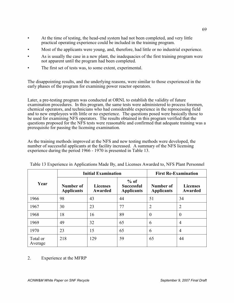
69
ACNW&M White Paper on SNF Recycle September 9, 2007 Final Draft
• At the time of testing, the head-end system had not been completed, and very littlepractical operating experience could be included in the training program.
• Most of the applicants were young, and, therefore, had little or no industrial experience.
• As is usually the case in a new plant, the inadequacies of the first training program werenot apparent until the program had been completed.
• The first set of tests was, to some extent, experimental.
The disappointing results, and the underlying reasons, were similar to those experienced in theearly phases of the program for examining power reactor operators.
Later, a pre-testing program was conducted at ORNL to establish the validity of futureexamination procedures. In this program, the same tests were administered to process foremen,chemical operators, and technicians who had considerable experience in the reprocessing fieldand to new employees with little or no experience. The questions posed were basically those tobe used for examining NFS operators. The results obtained in this program verified that thequestions proposed for the NFS tests were reasonable and confirmed that adequate training was aprerequisite for passing the licensing examination.
As the training methods improved at the NFS and new testing methods were developed, thenumber of successful applicants at the facility increased. A summary of the NFS licensingexperience during the period 1966 - 1970 is presented in Table 13.
Table 13 Experience in Applications Made By, and Licenses Awarded to, NFS Plant Personnel
Year
Initial Examination First Re-Examination
Number ofApplicants
LicensesAwarded
% ofSuccessfulApplicants
Number ofApplicants
LicensesAwarded
1966 98 43 44 51 34
1967 30 23 77 2 2
1968 18 16 89 0 0
1969 49 32 65 6 4
1970 23 15 65 6 4
Total orAverage
218 129 59 65 44
2. Experience at the MFRP
70
ACNW&M White Paper on SNF Recycle September 9, 2007 Final Draft
During 1971 - 1972, the operators of the General Electric Company’s fuel reprocessing plant atMorris, Illinois, underwent formal training to prepare them for licensing. Of the 65 personsincluded in the program, only two failed to qualify for licensing. Many of the candidates fortraining in the MFRP plant had been licensed previously in the NFS plant and had obtainedemployment with General Electric when the NFS facility at West Valley, New York ceasedoperation. Operators in two general categories were trained for operation in the plant(mechanical processes and remote process equipment). In addition, several senior operatorswere trained for supervisory roles. It was estimated that more than 220 man-days of effort wereexpended for each candidate in the training program. The estimated cost for this undertaking,including salary, overhead, and training, was established at $25,000 per individual. This costwould be much higher today, of course, because of inflation.
3. Experience at BNFP
BNFP was very nearly completed when the U.S. national policy stopping commercial fuelreprocessing was instituted. The pre-startup staff of the BNFP included a cadre of operators whohad been involved in training and retraining over the previous one-to-four year period. Inaddition to the operator training program, programs for others such as analytical laboratorytechnicians and security patrol officers were also conducted. These programs were necessary toensure that all operations would be carried out correctly, not only for safety related reasons, butalso for safeguards- related and physical security-related reasons.
The operations personnel and analytical technicians at the BNFP were cross-trained. Securityofficers were also cross-trained in various areas of physical security. As a result, the personnelwere considered to be highly trained and knowledgeable in BNFP operations but would haverequired retraining at that time consistent with any systems modifications required to generate amore proliferation resistant fuel cycle operation.
Operators, technicians, and patrol officers in the various categories were not given the necessarylicensing examination to permit operation because BNFP licensing was terminated beforecompletion. However, because of the extensive training and retraining taking place duringcheckout and “cold”-run operation, it was expected that the failure rate during the licensingexamination would be low. The presence of more experienced personnel in any type ofoperating facility helps reduce the mistakes made by those who, although well trained, remaininexperienced.
4. Training for operation of the Rokkasho-Mura reprocessing plant
About 100 people were trained to operate the Japanese Rokkasho-Mura reprocessing plant through four years of hands-on operating experience at the La Hague reprocessing plants.
5. Typical Reprocessing Plant Operator Training Program
The programs necessary to train reprocessing plant operators are far more rigorous than those

71
ACNW&M White Paper on SNF Recycle September 9, 2007 Final Draft
employed in conventional industrial chemical facilities. Further, the process of choosingcandidates with the necessary educational, psychological, and medical requirements to receivethis training is a prime concern. The selection of candidates who cannot pass the requiredcertification of licensing examinations results in a financial burden to the enterprise. In addition,unsatisfactorily trained individuals tend to jeopardize safety and hamper efficient operation ofthe plant under normal as well as abnormal conditions.
Current NRC requirements for training and certification of operators working in the nuclearpower industry and in nuclear power plants are found in 10 CFR Part 26 and 10 CFR Part 54. Inaddition NRC form 398, “Personal Qualification Statement – Licensee,” gives requirements formanipulating controls of a licensed facility. Appendix D presents additional details on operatorlicensing.
The qualifications of applicants for operator licenses are determined through two methods oftesting: (1) written examinations covering categories such as physics, chemistry, mechanicalprocessing systems, chemical processing systems, equipment and instrumentation, power andauxiliary systems, administrative and procedural rules, and radiological safety; and (2) an oralexamination.
The time required to adequately train an operator was found to be approximately 1 to 1.5 years.
The qualifications of the initial operators for future reprocessing/recycling plants is yet to beestablished, as the role of the DOE and the level of its interaction with the NRC and potentialcommercial owner/operators has yet to be established.
E. Needed Improvements
The proposed GNEP and closely related AFCI has as one of its cornerstones the developmentand reduction to practice of spent nuclear fuel separations processes that leave Pu primarily withactinides other than uranium. This necessitates equipment and methods for tracking, assay andaccountability of the fissile material content of separations process streams that have not beenfaced heretofore in this country. The processes proposed above will require equipment,processes and detectors for real-time tracking and monitoring and fissile content assay ofmaterials used in fabrication of fuels from fissile material from the separations processes.
1. Improved Processes
Precise and accurate tracking, detecting, monitoring and assaying the Pu/LEU content of productand waste streams from separations and fabrication processes will be required for any nuclearfuel recycle plants with improved proliferation resistance.
Computer programs to record, evaluate, interpret and provide real-time output from processequipment and fissile material monitors to local and central monitoring stations are requirements
72
ACNW&M White Paper on SNF Recycle September 9, 2007 Final Draft
for the integrated, large-scale data handling programs for management of data from all parts ofthe fuel cycle plant (process control, process monitoring, material transfer, material inventory,portal monitoring) to improve plant proliferation resistance by interrelating and cross checkingdisparate sources of information, as well as to improve plant efficiency. Plant operatingparameters should be compared on a continuous basis with computer simulated normal plantoperating parameters to detect, evaluate and report off-normal operation both locally andremotely as a check on possible illicit operations and improper plant operation. These factorsare enlarged upon below.
2. Improved Equipment
Process equipment are required for real-time monitoring and assay of fissile materials present inreprocessing and fabrication plants for fuels from separations processes containing a mixture ofactinides that are to be fabricated without further purification for use in reactors. Equipment forreal-time monitoring of spent fuel separations processes based on recent advances ininstrumentation and controls and adaptations of equipment and computerized analysis of dataalready in use can make possible improved tracking of fissile material through the processingsteps. Flow rates through pipes and process equipment, e.g., centrifugal contactors, pumps,pulse columns, mixer-settlers, and centrifuges, can be better measured and controlled than in thepast. Volume and concentration measurements can be made with greater precision and accuracyin feed and product tanks, thus improving material accountability. Fissile materialconcentrations and amounts can be measured through the use of better sampling and analysistechniques and subsequent computerized analysis of the data. For example, more and betterenergy spectra measurements and spectrum resolution can be obtained using technology andtools already available. Flow rates of UF6 can now be measured accurately. These types ofimproved measurements make possible location, identification and quantification of chemicaland isotopic species of interest.
3. Security and Safeguards
In addition to the normal industrial fences and barriers, nuclear facilities have additionalrequirements for both physical security and nuclear material safeguarding. These tworequirements often, but not always, overlap. In light of potential terrorist threats, security andsafeguards activities are being stressed, and additional measures are being put into place.
Physical, psychological and mental requirements of the guard and security forces are specified. These are under continuous review as threat levels are reassessed. Entry portals, coded badges,and other measures are used to control and monitor both personnel and equipment egress andingress. Internal and external portal monitors are required. Periodic physical inventories ofobjects containing fissile material are to be performed.
4. Detectors
The proposed separations processes will require equipment, processes and detectors for real-timetracking and monitoring and fissile content assay of materials used in fabrication of fuels andfissile material from the low-decontamination separations processes.
73
ACNW&M White Paper on SNF Recycle September 9, 2007 Final Draft
Improvements in the proliferation resistance of nuclear fuel reprocessing plants through use ofimproved detectors are possible in a variety of areas. Personnel monitoring and record keepingof movements and activities of personnel is easily achieved through a variety of methods toensure there are no illicit activities. Speciation technology (e.g., radiochemical methods for traceconcentrations; laser spectroscopy; X-ray absorption fine structure spectroscopy; magneticresonance techniques, redox speciation; ion-selective electrodes) for materials of interest hasimproved greatly in recent years. Computerized recording and analysis of data from the sensingand measuring equipment, conducted both locally and at remote locations, permits detection ofoff-normal operating conditions. This capability is useful both for monitoring plant operationsand for maintaining accountability of fissile material. Potential areas of application of some ofthese new and novel technologies are discussed below.
5. Material Accountability
As already noted, all nuclear material separations and fuel fabrication processes produceproducts and wastes that contain fissile material. The amount of fissile material going to wastecan be significant for high-throughput processes that operate over relatively long periods of time.If it were to be recovered it could potentially exceed a critical mass although the fissile materialis typically very dilute and a major effort would be required to recover what was previouslydeemed to be irrecoverable. Highly sensitive detection and measurement equipment is nowavailable to monitor and assay the plutonium and enriched uranium content of waste streamsfrom separations plants and from both enriched uranium and MOX fuel fabrication processes.
A special accountability problem arises when the minor actinides (Np, Am, Cm) are not insecular equilibrium because their concentrations are currently often inferred from calculationsbased on assumed equilibrium when the concentrations are not readily measured. When decaychains are broken, accountability can become much more difficult. It is important to keep this inmind, especially when both Pu and U are present.
Computerized, integrated, large-scale data handling programs for management of data from allparts of the fuel cycle plant (process control, process monitoring, material transfer, materialinventory, portal monitoring) will be a necessary adjunct to any modern reprocessing or fuelfabrication plant. These programs can greatly improve plant proliferation resistance byinterrelating and cross checking disparate sources of information.
Considerable effort, both nationally and internationally, is required between the groupsresponsible for establishing the permissible significant (SIGMA) Pu inventory differences (ID).
As shown in the Table 14 [Pasamehmetoglu, 2006], there is a large difference between theIAEA, the NRC and the DOE with regard to the Sigma ID requirements, and the frequency ofboth long-term shutdown inventory and interim frequency requirements.
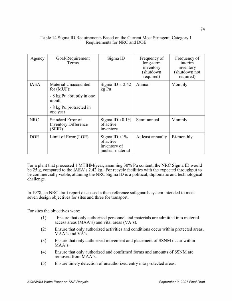
74
ACNW&M White Paper on SNF Recycle September 9, 2007 Final Draft
Table 14 Sigma ID Requirements Based on the Current Most Stringent, Category 1Requirements for NRC and DOE
Agency Goal/RequirementTerms
Sigma ID Frequency oflong-terminventory(shutdownrequired)
Frequency ofinterim
inventory(shutdown not
required)
IAEA Material Unaccountedfor (MUF):
- 8 kg Pu abruptly in onemonth
- 8 kg Pu protracted inone year
Sigma ID # 2.42kg Pu
Annual Monthly
NRC Standard Error ofInventory Difference(SEID)
Sigma ID #0.1%of activeinventory
Semi-annual Monthly
DOE Limit of Error (LOE) Sigma ID #1%of activeinventory ofnuclear material
At least annually Bi-monthly
For a plant that processed 1 MTIHM/year, assuming 30% Pu content, the NRC Sigma ID wouldbe 25 g, compared to the IAEA’s 2.42 kg. For recycle facilities with the expected throughput tobe commercially viable, attaining the NRC Sigma ID is a political, diplomatic and technologicalchallenge.
In 1978, an NRC draft report discussed a then-reference safeguards system intended to meetseven design objectives for sites and three for transport.
For sites the objectives were:
(1) “Ensure that only authorized personnel and materials are admitted into materialaccess areas (MAA’s) and vital areas (VA’s).
(2) Ensure that only authorized activities and conditions occur within protected areas,MAA’s and VA’s.
(3) Ensure that only authorized movement and placement of SSNM occur within MAA’s.
(4) Ensure that only authorized and confirmed forms and amounts of SSNM areremoved from MAA’s.
(5) Ensure timely detection of unauthorized entry into protected areas.
75
ACNW&M White Paper on SNF Recycle September 9, 2007 Final Draft
(6) Ensure that the response to any unauthorized activity is timely, effective, andappropriate to the particular contingency.
(7) Ensure the presence of all SSNM in the plant by location and quantity.”
For transport the three design objectives were:
(1) “Restrict access to and personnel activity in the vicinity of transports.
(2) Prevent unauthorized entry into transports or unauthorized removal of SSNMfrom transports.
(3) Ensure that the response to any unauthorized attempt to enter vehicles and removematerials is timely, effective, and appropriate for the particular contingency.”
It was the belief at the time that the referenced system, based upon supporting studies andanalyses, “was consistent with the safeguards requirements imposed by 10 CFR Parts 70 and73.” A generally conservative approach was adopted to further increase confidence in thatfinding.
Five alternative safeguards options were also examined, and, in general, these measures affordedthe potential for improving overall safeguards performance or reducing the overall societalimpacts attributable to safeguards. None significantly outweighed any other in general efficacy.
It should be noted that the NRC’s safeguards program for commercial licensees is part of anational safeguards structure introduced initially to protect defense-related SSNM. Thatstructure included three primary components: 1) intelligence gathering, 2) site and transportationsecurity, and 3) recovery of lost material. Only the second component, site and transportationsecurity, which involves physical security and material control, would fall primarily withinNRC’s field of responsibility. The other two, intelligence and recovery operations, wouldremain the responsibility of other agencies such as the FBI, the National Security Council, DOE,and State and local law enforcement agencies. NRC collaborates with these other agencies indeveloping contingency plans for reacting to and dealing with theft or diversion, but does notparticipate in intelligence operations or physically take part in recovery operations.
76
ACNW&M White Paper on SNF Recycle September 9, 2007 Final Draft
V. OVERVIEW OF ADVANCED SPENT NUCLEAR FUEL RECYCLE INITIATIVES
The National Energy Policy (NEP) [NEP, 2001] issued by the President Bush in May, 2001recommended expanded use of nuclear energy in the U.S., including development of advancednuclear fuel cycles, reprocessing and fuel treatment technologies. Consistent with thePresident’s policy, DOE adopted an “integrated strategy” with four initiatives: Nuclear Power2010 program; the Advanced Fuel Cycle Initiative (AFCI); the Generation IV Nuclear EnergySystems initiative; and the Nuclear Hydrogen initiative. Additionally, on February 6, 2006, theSecretary of Energy launched GNEP, a comprehensive international strategy to expand the safeuse of nuclear power around the world.
A. Advanced Fuel Cycle Initiative
The purpose of the DOE AFCI program is to develop fuel systems and enabling fuel cycletechnologies for GEN IV reactors and future reactors in support of GNEP. DOE anticipates thatAFCI will provide options for the management of spent nuclear fuel through treatment andtransmutation of radionuclides that will reduce the cost, hazards and volume of HLW disposalin repositories, reduce the amount of plutonium accumulating in the nuclear fuel cycle, andrecover for beneficial use the energy potential remaining in spent fuel. DOE plans call forsystems analysis to be an important part of the ongoing AFCI program and have an increasedrole during the next few years. The planned systems analysis will investigate key issues such asthe required rate of introduction of advanced burner reactors (ABRs) and actinide separationsfacilities to avoid the need for a second HLW repository early in this century, and a detailedstudy of the technical requirements for the facilities and how the facilities might support the toplevel goals of the program. DOE plans to use the results of these analyses to establish the basisfor each key decision in the AFCI program and for GNEP program planning.
AFCI is organized into the following program elements:
• Separations
• Fuels
• Transmutation
• University Programs
The purpose of each element is summarized below.
1. Separations
Separation processes will be devised to recover plutonium in a way such that it is neverseparated from at least some transuranic actinides and possibly some fission products. Essentially all of the transuranic elements in addition to the 137Cs and 90Sr will also be removedfrom the waste going to the geologic repository. Such removal would reduce the heat load in therepository, greatly increasing the number of fuel assemblies whose wastes go to the repository,and consequently obviating the need for additional repository space for many decades. Theseseparation technologies are not alternatives to a geologic repository but could help reduce the
77
ACNW&M White Paper on SNF Recycle September 9, 2007 Final Draft
cost and extend the life of a geologic repository.
2. Fuels
Fuel forms for advanced fast-spectrum transmutation reactors that are planned for transmutingtransuranic actinides (i.e., Np, Pu, Am, and Cm) to fission products are being developed. Oxide,nitride, carbide, and metallic fuels are being considered. The AFCI is also developing fuels forGEN-IV power reactors.
3. Transmutation
Transmutation is a process by which long-lived radioactive isotopes, especially actinides such asplutonium and neptunium, but also selected fission products such as 99Tc and 129I, are convertedto shorter-lived fission products or stable isotopes by fission and/or neutron capture fromneutrons generated in a reactor or by the interaction of high-energy ions from a particleaccelerator with a metal target such as mercury, tungsten, or bismuth. Theoretically, thepreferred neutron source to fission actinides is one of high average neutron energy (yielding ahigh neutron fission-to-capture ratio), high flux (to which the transmutation rate is proportional),and large core volume (to accommodate more actinides). This has lead to a preference for fastreactors as the neutron source. Transmutation of fission products is usually more efficient in thelow-energy neutron spectrum typical of thermal reactors such as LWRs, but DOE is currentlyfocusing on actinide transmutation and, thus, on development of fast reactors with the leadcandidate being a sodium-cooled reactor with stainless-steel-clad fuel.
4. University Programs
The goal of the AFCI University Programs element is to foster education of the next generationof scientists and engineers who will support the growth of nuclear power. This goal is to beachieved primarily by funding infrastructure upgrades at universities and by education andresearch.
a. University Nuclear Infrastructure (UNI)
This program brings together several program elements supporting the increasingly vitaluniversity nuclear engineering infrastructure. Program elements include:
Innovations in Nuclear Infrastructure and Education (INIE)
This program strengthens the Nation's university nuclear engineering education programsthrough innovative use of the university research and training reactors and encouraging strategicpartnerships among the universities, the DOE national laboratories, and U.S. industry. Currentlythere are 6 university consortia providing support for 38 universities in 26 states under the INIEprogram.
78
ACNW&M White Paper on SNF Recycle September 9, 2007 Final Draft
Reactor Fuel Assistance
The DOE provides fresh fuel to, and takes back spent fuel from, university research reactors.There are currently 27 operating university research reactors at 26 institutions in the UnitedStates.
Reactor Upgrades
The DOE provides assistance to universities to improve the operational and experimentalcapabilities of their research reactors. Grants are provided to the universities to purchaseequipment and services necessary to upgrade the reactor facilities, such as reactorinstrumentation and control equipment, data recording devices, radiation, security, and airmonitoring equipment, and gamma spectroscopy hardware and software.
Reactor Sharing
Through this assistance effort, DOE enables universities with reactors to "share" access to theirfacilities with students and faculty at other institutions who lack such a facility. The reactors aremade available for use in research, experiments, material irradiations, neutron activation analysisand training, and for facility tours and other educational activities.
b. Nuclear Engineering Education Research (NEER) Grants
This highly competitive peer-reviewed program provides grants to nuclear engineering facultyand students for innovative research in nuclear engineering and related areas. The awards runfrom one to three years and are granted in nine separate technical areas related to nuclearengineering: reactor physics, reactor engineering, reactor materials research, radiologicalengineering, radioactive waste management, applied radiation science, nuclear safety and riskanalysis, innovative technologies, and health physics.
c. Other University Support Activities
DOE/Industry Matching Grants
The Department of Energy and participating companies provide matching funds of up to $60,000each to universities for use in funding scholarships, improving nuclear engineering and sciencecurricula and modernizing experimental and instructional facilities. Nuclear Engineering/HealthPhysics Fellowships and Scholarships to Nuclear Science and Engineering Programs atUniversities are provided.
79
ACNW&M White Paper on SNF Recycle September 9, 2007 Final Draft
Radiochemistry
DOE awards three-year grants to support education activities in the field of radiochemistry in theUnited States. Radiochemistry is linked to several national priorities including medicine, energyand national defense.
Nuclear Engineering and Science Education Recruitment Program
This program is designed to increase the number of students entering a university nuclearengineering course of study by developing a core curriculum to instruct high school scienceteachers in nuclear science and engineering topics through the use of teaching modules, teacherworkshops and other outreach activities.
Summer Internships at National Laboratories
The Office of Nuclear Energy offers summer internships in technical areas related to nuclearengineering to undergraduate and graduate students at the Idaho National Laboratory.
International Student Exchange Program (ISEP)
The ISEP sponsors U.S. students studying nuclear engineering for 3-4 months abroad doingresearch at nuclear facilities in Germany, France, and Japan. These three countries send theirstudents to the U.S. for reciprocal internships at DOE national laboratories.
B. Global Nuclear Energy Partnership (GNEP)
GNEP is a broadly scoped DOE program the goal of which is promoting beneficial internationaluses of nuclear energy through a multi-faceted approach. Many of the ideas explored earlier byINFCE are embodied in GNEP, which is essentially an updated expression and extension ofthose ideas.
DOE has entered a Notice of Intent (NOI) to Prepare a Programmatic Environmental ImpactStatement (PEIS) for the Global Nuclear Partnership in the Federal Register [DOE, 2007]. ThisNOI gives a detailed statement of what is intended to be provided in the GNEP PEIS as well asconsiderable information on what DOE’s concept of what GNEP itself is.
1. GNEP Goals
GNEP continues to evolve in response to new information, new international alliances, andchanging program leadership. The general goals of GNEP as expressed by DOE in its strategicplan [GNEP, 2007a] are as follows:
80
ACNW&M White Paper on SNF Recycle September 9, 2007 Final Draft
“The United States will build the Global Nuclear Energy Partnership to work withother nations to develop and deploy advanced nuclear recycling and reactortechnologies. This initiative will help provide reliable, emission-free energy withless of the waste burden of older technologies and without making availableseparated plutonium that could be used by rogue states or terrorists for nuclearweapons. These new technologies will make possible a dramatic expansion ofsafe, clean nuclear energy to help meet the growing global energy demand.”
DOE plans three facilities to implement GNEP:
(1) an industrial-scale nuclear fuel recycling center (Consolidated Fuel TreatmentCenter, CFTC) to separate the components of spent fuel required by GNEP,
(2) a reactor (Advanced Burner Reactor, ABR) to fission the actinides yieldingfission products that are more readily managed while producing electricity. DOEis leaning toward a sodium-cooled fast reactor for the ABR.
(3) an advanced fuel cycle research facility (Advanced Fuel Cycle Facility, AFCF) toserve as an R&D center of excellence for developing transmutation fuels andimproving fuel cycle technology.
Two approaches are being used to develop these three facilities. The CFTC and the ABR wouldbe led by industry with technology support from laboratories, international partners, anduniversities. The AFCF would be located at a government site and research therein would befunded by DOE and led by the national laboratories to create the technology used in the CFCTand fuels for the ABR.
DOE expects that the components of GNEP would provide the following benefits:
• Expand domestic use of nuclear power and reduce dependence on fossil fuels;
• Demonstrate more proliferation-resistant fuel recycle processes;
• Minimize high-heat-output nuclear waste and thus obviate the need for additional U.S.geologic repositories before 2100;
• Develop and demonstrate ABRs to produce energy from recycled fuel;
• Establish reliable fuel services to participating nations by providing fuel on a lease-and-return basis;
• Demonstrate small-scale reactors;
• Develop enhanced nuclear safeguards by designing safeguards directly into nuclearfacilities and reactors and by enhancing IAEA safeguards capabilities.
2. GNEP Timetable – phased approach
81
ACNW&M White Paper on SNF Recycle September 9, 2007 Final Draft
On August 3, 2006 DOE announced $20 Million for GNEP siting studies and sought furthercooperation with industry through issuance of a request for Expressions of Interest (EOI) inlicensing and building a CFTC and a ABR.
The GNEP program is phased. Each phase would begin after a decision based on the results ofthe previous phase and an assessment of the risks associated with proceeding to the next phase. DOE has stated that it will proceed to detailed design and construction of the GNEP facilitiesafter it is confident that the cost and schedules are understood and after the project managementframework that will allow these projects to succeed is in place. DOE plans a major decision onthe future of GNEP in June, 2008 and has not been willing to specify potential schedules beyondthis decision.
It is anticipated that NRC will regulate CFTC and ABR. The AFCF will be built on a DOE siteand is not be expected to be licensed by the NRC. Because the GNEP policy and technologicalapproaches to implementing the policy continue to change it is important that NRC have astrategy to accommodate the changes, both in allocating personnel and budgeting for thechanges.
C. Russian “Equivalent” Proposal (Global Nuclear Infrastructure - GNI)
Russian President Putin put forward in 2006 a broad non-proliferation initiative called the GlobalNuclear Infrastructure (GNI) envisioning the establishment of International Nuclear Centers, andoffered to host the first such center in Russia. The proposed Centers would provide participatingnations with full “nuclear fuel cycle services,” including enriching uranium, fabricating freshnuclear fuel, and storing and reprocessing spent nuclear fuel.
In states not possessing nuclear weapons, uranium enrichment and spent fuel reprocessing areactivities permitted under the terms of the Nuclear Non-Proliferation Treaty (NPT), but they areconsidered to pose significant proliferation risks because they can provide access to weapons-usable nuclear material. The Russian Nuclear Center proposal would concentrate such activitiesin states already possessing nuclear weapons and limit the introduction of enrichment andreprocessing facilities in non-nuclear weapons states.
Russia has stated that it would be ready to set up a pilot international enrichment center. Thiscenter would provide non-weapons nuclear power states with assured supplies of low-enricheduranium for power reactors, giving them equity in the project, but without allowing them accessto the enrichment technology. The existing uranium enrichment plant at Angarsk - the smallestof three Siberian plants - will feed the international center which will be under IAEAsupervision. The material will be under safeguards. Russian legislation is needed to separate thefacility from the defense sector and open it to international inspection, as well as to provide for ashareholding structure for other countries involved with the center.
GNI will be the first expression of President Putin’s initiative which is in line with IAEA’s 2003proposal for Multilateral Approaches to the Nuclear Fuel Cycle (MNA). GNEP proposalsinvolving such centers are very similar [WNA, 2006], and collaboration with the Russianinitiative is anticipated.
82
ACNW&M White Paper on SNF Recycle September 9, 2007 Final Draft
D. Generation IV Nuclear Reactors
The Generation IV International Forum (GIF), was chartered in May 2001 to lead thecollaborative efforts of the world’s leading nuclear technology nations to develop nextgeneration nuclear energy systems (reactors) to meet the world’s future energy needs. Thisinternational effort reached a major milestone on February 28, 2005, as five of the forum’smember countries signed the world’s first agreement aimed at the international development ofadvanced nuclear energy systems.
Five distinctly different reactor systems were identified for development. Initial emphasis wasto be placed on those reactors whose next generation would be evolutionary improvements ofPWRs and BWRs rather than radical departures from existing technology. All five of thereactors have operating experience (PWR, BWR, Sodium Fast Reactors, and HTGR) orextensive research and development (MSR)
E. Nuclear Power 2010
The technology focus of the Nuclear Power 2010 program is on Generation III+ advanced lightwater reactor designs which offer advancements in safety and economics over the Generation IIIdesigns licensed by the Nuclear Regulatory Commission (NRC) in the 1990's. To enable thedeployment of new Generation III+ nuclear power plants in the United States in the relativelynear-term, it is essential to complete the first-of-a-kind Generation III+ reactor technologydevelopment and to demonstrate the use of untested Federal regulatory and licensing processesfor the siting, construction, and operation of new nuclear plants. DOE has initiated cooperativeprojects with industry to obtain NRC approval of three sites for construction of new nuclearpower plants under the Early Site Permit (ESP) process, to develop application preparationguidance for the combined Construction and Operating License (COL) and to resolve genericCOL regulatory issues, to obtain NRC approval of COL applications. The COL process is a"one-step" licensing process by which nuclear plant public health and safety concerns areresolved prior to commencement of construction, and NRC approves and issues a license tobuild and operate a new nuclear power plant.
Although DOE is supporting industrial development of improved and advanced reactor designsthere will be few if any new reactor construction starts before 2010. However, there has been asubstantial number of operating license renewal applications. As of August 2007 the NRC hadreceived license renewal applications for 57 reactor units and had approved 20-year licenseextensions for 48 reactor units. Utilities have indicated they intend to apply for new reactorconstruction and operating licenses in the near future.
83
20 Separation factor is defined as the concentration of the species of interest in the feed to one stage of the separationprocess divided by its concentration in the product of that stage of the separation process.
ACNW&M White Paper on SNF Recycle September 9, 2007 Final Draft
VI. ADVANCED FUEL REPROCESSING TECHNOLOGY
In the early years of reprocessing in the U.S. the goal was to separate pure plutonium containinga high proportion of 239Pu for use in nuclear weapons. Irradiations in the plutonium productionreactors at the DOE Hanford and Savannah River sites for short irradiation times were carriedout to minimize generation of undesirable higher mass number plutonium isotopes. As interestin commercial power-producing reactors grew, the emphasis changed from weapons plutoniumproduction operating conditions to higher fuel burnups to maximize energy production andminimize cost. This emphasis led to a smaller proportion of weapons-grade 239Pu and largerproportions of 240Pu, 241Pu, and 242Pu in the spent fuel.
The DOE’s ongoing reprocessing development program includes an interest in proliferation-resistant processes. One approach to increasing proliferation resistance is to eliminate theseparation of a pure plutonium product. Other important goals for future reprocessing plantsinclude minimizing the volume of radioactive wastes produced by the plant, decreasing losses offissile and fertile elements to waste, most notably Pu and U, and removing heat-producingradionuclides in the HLW (137Cs and 90Sr in the relatively short term and the actinides, primarilyPu, Np, Am and Cm, in the long term). Many of the processes under development by DOE arenot yet optimized with respect to minimizing the number of separation cycles or achieving therequisite separation efficiencies.
Figure B1 in Appendix B shows the relative contributions of fission products and actinides tothe heat produced by PWR fuel irradiated to 51 GWd/MTIHM as a function of time out of thereactor. Upon examination of radionuclide contributions it is apparent that removing actinides,most notably 241Am and Pu isotopes, greatly reduces the heat production in the waste from spentfuel reprocessing. This fact is the impetus for actinide removal in the UREX processes.
It is important to know the efficiencies of the separations processes used in the flowsheets. Thisinformation is obtained as nearly as possible through laboratory experiments with non-radioactive materials, followed by experiments with radioactive tracers, then with small amountsof irradiated fuel, and finally by small-scale integrated process experiments with irradiated fuel. At the same time the various pieces of process equipment are tested individually and then asintegrated systems to ensure process goals will be met. These latter tests may be performedwithout using radioactive material, or with uranium only. Data from the laboratory andequipment tests are used to select and design pilot plant recycle facilities. These tests also yield data on separation factors20, which are a measure of separations efficiencies for the suite ofelements of interest. Besides uranium and plutonium, it is very important to have separationsdata on Cs, Sr, Tc, I, Np, Am, Cm and the lanthanide elements. The importance of these dataderives from the fact that the extent of separation determines the distribution of theseradionuclides among the products and waste streams and thus determines the need for additionalcleanup or helps define disposal routes. Radionuclides, previously considered to be of littleimportance, that may be important in the future include tritium, 85Kr and 14C.
Because the power densities and fuel burnups in commercial power reactors have been
84
ACNW&M White Paper on SNF Recycle September 9, 2007 Final Draft
increasing steadily as more and more reliable information on reactor and fuel performance hasbecome available, and because the half lives of the radioisotopes cover an enormous range, it isvery important to know how much of each of them is produced and how long they are permittedto decay before designing the process or processes to be used in a reprocessing facility and thedegree of separation required. Decay time is of particular importance in the case of 241Am mostof which grows in after the fuel is removed from the reactor as a result of 241Pu decay.
All of this information goes into establishing mass balance and equipment flowsheets. Withsuch a wide range of variables (fuel burnup, reactor neutron flux, radioactive decay, a very largenumber of radionuclides, degree of separation for individual radioisotopes or groups ofradioisotopes, and equipment options) the number of possible flowsheets becomes very large. Considerations such as degree of separations sought, process simplicity, ease of processoperation, cost, volume of wastes generated, safety, regulations, criticality, and proliferationresistance of the processes are helpful in winnowing down the processes that are actually worthyof study and adoption.
A. UREX Processes
GNEP has conceived of a suite of UREX processes, each of which consists of a series of stepsdesigned to remove successively specific groups of radionuclides to tailor products andcompositions of desired product and waste streams. The PUREX process can be modifiedreadily to be the first step of any of the UREX (URanium EXtraction) processes (five variantshave been considered in GNEP). This step is followed by processes to remove major heat-producing radionuclides from wastes going to the repository and to aggregate transuranicactinides for recycle. In particular, DOE has been focusing on the UREX +1a flowsheet whichproduces fissile material products that contain separated uranium in one stream and all thetransuranic actinides in another. The transuranic actinides are to be fabricated into reactor fuelfor transmutation and energy. There has recently been increasing interest in the UREX+2flowsheet, which separates Am/Cm/lanthanides from the Pu/Np, and the UREX+3 process,which separates the lanthanides from the Am/Cm/lanthanide mixture.
One objective of the UREX processes is to increase the proliferation resistance of fuel recycle byavoiding the production of a pure plutonium stream and to fission plutonium and the otheractinides to produce energy. A second objective is to remove the major sources of decay heatthat limits the spacing of waste packages in a geologic repository. Figure B1 in Appendix Bshows that the heat production rate of the actinides exceeds that of the fission products in thelong term, and after about 70 years the predominance of the heat is produced by the actinides,illustrating the advantage of their removal from the waste sent to the repository. This illustratesthe potential advantage of keeping the lanthanides with the actinides from the point of view ofproliferation resistance. Any potential disadvantages subsequently arising during transmutationwould need to be evaluated, but they are not expected to be large.
The UREX processes combine the modified PUREX process flowsheet with other solventextraction processes that have many features in common. The PUREX process step is amodification of the conventional PUREX process in which the plutonium is prevented frombeing extracted with the uranium in the first UREX process step by adding a plutonium reductantto the first extraction cycle. Plutonium extraction is prevented by chemically reducing
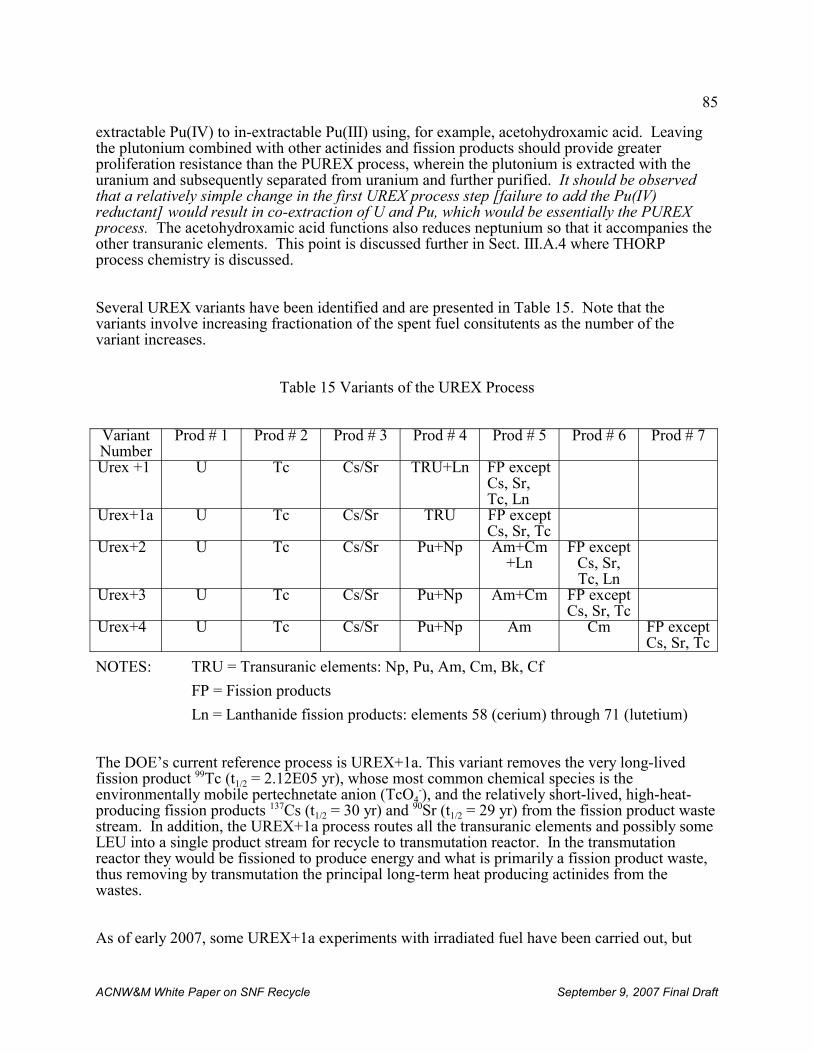
85
ACNW&M White Paper on SNF Recycle September 9, 2007 Final Draft
extractable Pu(IV) to in-extractable Pu(III) using, for example, acetohydroxamic acid. Leavingthe plutonium combined with other actinides and fission products should provide greaterproliferation resistance than the PUREX process, wherein the plutonium is extracted with theuranium and subsequently separated from uranium and further purified. It should be observedthat a relatively simple change in the first UREX process step [failure to add the Pu(IV)reductant] would result in co-extraction of U and Pu, which would be essentially the PUREXprocess. The acetohydroxamic acid functions also reduces neptunium so that it accompanies theother transuranic elements. This point is discussed further in Sect. III.A.4 where THORPprocess chemistry is discussed.
Several UREX variants have been identified and are presented in Table 15. Note that thevariants involve increasing fractionation of the spent fuel consitutents as the number of thevariant increases.
Table 15 Variants of the UREX Process
VariantNumber
Prod # 1 Prod # 2 Prod # 3 Prod # 4 Prod # 5 Prod # 6 Prod # 7
Urex +1 U Tc Cs/Sr TRU+Ln FP exceptCs, Sr,Tc, Ln
Urex+1a U Tc Cs/Sr TRU FP exceptCs, Sr, Tc
Urex+2 U Tc Cs/Sr Pu+Np Am+Cm+Ln
FP exceptCs, Sr,Tc, Ln
Urex+3 U Tc Cs/Sr Pu+Np Am+Cm FP exceptCs, Sr, Tc
Urex+4 U Tc Cs/Sr Pu+Np Am Cm FP exceptCs, Sr, Tc
NOTES: TRU = Transuranic elements: Np, Pu, Am, Cm, Bk, Cf
FP = Fission products
Ln = Lanthanide fission products: elements 58 (cerium) through 71 (lutetium)
The DOE’s current reference process is UREX+1a. This variant removes the very long-livedfission product 99Tc (t1/2 = 2.12E05 yr), whose most common chemical species is theenvironmentally mobile pertechnetate anion (TcO4
-), and the relatively short-lived, high-heat-producing fission products 137Cs (t1/2 = 30 yr) and 90Sr (t1/2 = 29 yr) from the fission product wastestream. In addition, the UREX+1a process routes all the transuranic elements and possibly someLEU into a single product stream for recycle to transmutation reactor. In the transmutationreactor they would be fissioned to produce energy and what is primarily a fission product waste,thus removing by transmutation the principal long-term heat producing actinides from thewastes.
As of early 2007, some UREX+1a experiments with irradiated fuel have been carried out, but
86
21 The results in ORNL/TM-2007/24 lead the authors to conclude “Because the ABR design has been optimized at~840 Mwt, a large number (33-90) of ABRs would be required to transmute the ~23 MT/year TRU actinidescurrently produced in ~2000 MT/year of low-enriched uranium spent fuel; in comparison , 10-24 existing (or new)3400 Mwt LWRs would be sufficient.”
22 The dissolver off-gas system for the THORP reprocessing plant has a 99% removal goal for iodine and 99.9% isroutinely achieved. 14C removal efficiency is similar.
ACNW&M White Paper on SNF Recycle September 9, 2007 Final Draft
there have been no engineering-scale demonstrations. The difficulties associated with operatingthe four sequential solvent extraction processes in the UREX +1a flowsheet continuously havenot yet been addressed. These difficulties are likely to pose serious operational challenges asone observes that all UREX variants require multiple processes operating sequentially, usingdiffering extractants, different equipment, and different solvent cleanup and recycle processes. The staff operating such a plant will require extensive and expensive training. Additionally, ifone of the separations process steps became inoperable, the entire plant would be shut downbecause the individual processes must operate simultaneously unless substantial inter-processsurge capacity were included.
Flowsheet and process development is underway at ANL, INL, SRS and ORNL in hot cells atthe benchtop scale and is planned at the kilogram scale to establish the viability of the variousseparations processes. This work, especially sequential process operation in the hot cells, is veryimportant for establishing the feasibility and performance of the UREX+1a process. It will benecessary to accompany process development with engineering-scale testing of major equipmentpieces and processes.
The UREX+3 variant is noteworthy because it yields Am and Cm as a product stream separatefrom the Np and Pu. This feature may be of importance, depending on how the ~55,000 tonnesof long-cooled spent fuel currently in storage at the reactor sites or spent fuel storage sites isphased into the reprocessing plant processing schedule along with the 2200 tonnes of spent fuelbeing generated annually from the existing 104 commercial power reactors (plus the fuel fromany new reactors that come on line). Because of radioactive decay and their nuclear propertiesthe Am and Cm from spent fuel aged 35 to 40 years is more efficiently burned in LWRs than infast reactors [ORNL, 2007], a fact that has the potential to reduce the number of or to eliminatethe need for fast reactors currently planned for transmutation of actinides to fission products.21
Figure 14 is a block diagram of the UREX+1a process which shows the process steps as theHead End, Central, and Tail End unit operations. The head-end operations include chopping thefuel elements into small pieces, fuel dissolution, and feed clarification to provide the inputstream (H-5) to the central UREX +1a process. Additional head-end process steps will likelyalso include trapping and immobilizing the gases 85Kr, 129I, 14CO2 and 3H22. In addition, thehardware and hulls are shown to be compacted and packaged for disposal. These additionalhead-end steps are, with the exception of iodine retention and hardware and hull compaction, notcurrent reprocessing practice.
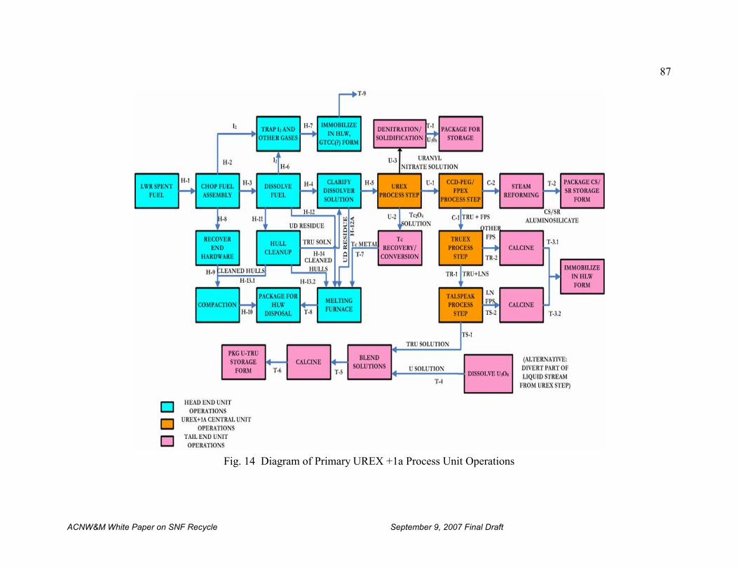
87
ACNW&M White Paper on SNF Recycle September 9, 2007 Final Draft
Fig. 14 Diagram of Primary UREX +1a Process Unit Operations
88
ACNW&M White Paper on SNF Recycle September 9, 2007 Final Draft
The central unit operation steps are discussed in detail below and provide the various streams forseparation and intermediate storage. The U and Tc are separated from the dissolver solution inthe UREX process step and then the Tc is removed by ion exchange. The uranium (urannylnitrate) product stream undergoes denitration and solidification and packaging for storage. TheTc is converted to metal for disposal, presumably with the fuel cladding hulls. 137Cs and 90Sr areseparated in the CCD-PEG process and stored as glass-bonded aluminosilicates afterimmobilization by steam reforming. The remaining fission products other than the lanthanidesare separated by the TRUEX process, vitrified, and sent to interim storage. The TRU elementsseparated from the lanthanides in the TALSPEAK process may be blended with uranium forcalcination, packaging and interim storage pending refabrication into transmutation reactor fuel. The lanthanides are combined with the other fission products. The waste forms and wastemanagement strategy outlined here should be regarded as provisional. The DOE is preparing awaste management strategy [Wigeland, 2007] to better define the wastes resulting from UREX.
Figures 15, 16,17, and 18 show more details on the four major processes in this flowsheet.
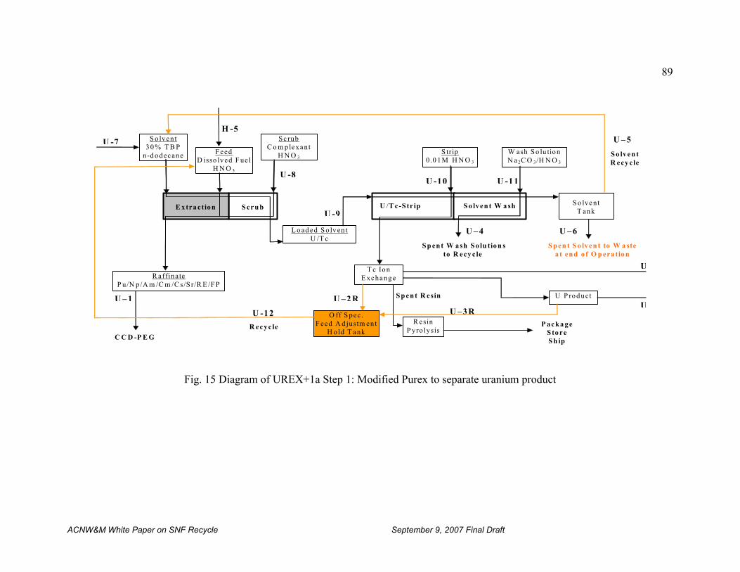
89
ACNW&M White Paper on SNF Recycle September 9, 2007 Final Draft
Fig. 15 Diagram of UREX+1a Step 1: Modified Purex to separate uranium product
P acka ge S tore S h ip
R ecyc le
U – 4
U -11
U /T c-S tr ip
S p en t R esin
U -7
U – 1
U -12
U –2 R
U –3R
S p en t S o lven t to W a ste a t en d o f O p eration
U –6
U – 5
S o lven tR ecy cle
S p en t W ash S o lu tion s to R ecy c le
U -10
U -9
U -8
U
U
H -5
S cru b E xtraction
S olven t 30 % T B P
n-d od ecane
S crub C o m ple xant
H N O 3F eed
D isso lved F ue lH N O 3
L o ad ed S o lven t U /T c
S trip 0 .0 1M H N O 3
T c Ion E xcha nge
S o lven t W a sh
W ash S o lu tionN a2C O 3/H N O 3
U P roduct
S o lve nt T ank
R esin P yro lysis
R affinate P u/N p /A m /C m /C s/S r/R E /F P
O ff S pec. F eed A d justm en t
H o ld T ank C C D -P E G
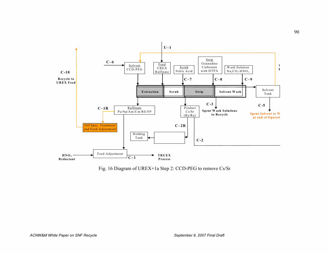
90
ACNW&M White Paper on SNF Recycle September 9, 2007 Final Draft
Fig. 16 Diagram of UREX+1a Step 2: CCD-PEG to remove Cs/Sr
C–1R
HN O 3 Reductant
TR U EX Process C –1
C -3
C-2
C
C-5
C–2R
R ecycle to UR EX Feed
C–9 C–8 C –7
U –1
C –6
Extraction Scrub Strip Solvent W ash
Solvent CCD -PEG
Feed U REX
Raffinate
Scrub Nitric Acid
Strip Guanadine Carbonate
with D TPA W ash SolutionN a2CO 3/H NO 3
Solvent Tank
Product Cs/Sr
(B a/Ru)
Spent Solvent to Wat end of O perati
SR
Raffinate Pu/Np/Am /C m/RE/FP
Holding Tank
Feed Adjustment
C -10
Spent W ash Solutions to Recycle
Off Spec. T reatment and Feed Adjustment
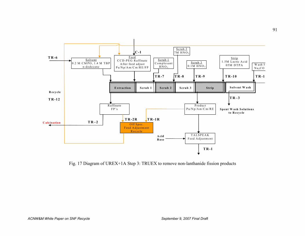
91
ACNW&M White Paper on SNF Recycle September 9, 2007 Final Draft
Fig. 17 Diagram of UREX+1A Step 3: TRUEX to remove non-lanthanide fission products
C alcin a tion
T R -1
T R -1
A cid B ase
T R –2 T R -2R
R ecycle
T R -12
T R -10 T R -9 T R -8 T R -7
C -1
T R -6
T R -1R
E xtraction S cru b 1 S cru b 2 S cru b 3 S trip
Strip 1 .5M L actic A cid
05M D T P A S crub 3
0 .1M H N O 3
Scrub 2 7M H N O 3
S crub 1 C o m plexant
H N O 3
Feed C C D -P E G R affinate
A fter feed ad just P u/N p/A m /C m /R E /FP
So lvent 0 .2 M C M P O , 1 .4 M T B P
n-dodecane
P roduc t P u/N p /A m /C m /R E
R affinate F P ’s
T R –3
O ff S pec. F eed A d justm ent
R ecycle T A LS P E A K
F eed A d justm ent
S o lvent W ash
W ash SN a2C O 3
S p ent W ash S o lution s to R ecyc le
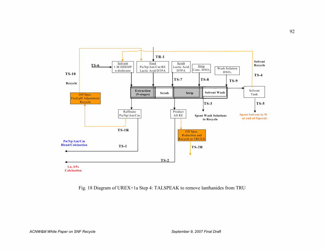
92
ACNW&M White Paper on SNF Recycle September 9, 2007 Final Draft
Fig. 18 Diagram of UREX+1a Step 4: TALSPEAK to remove lanthanides from TRU
TS-4
TS-6
TR-1
TS-7 TS-8
SolventRecycle
TS-2
TS-1
TS-10
TS-1R
TS-2R
Extraction (9-stages) Scrub Strip
Feed Pu/Np/Am/Cm/RE Lactic Acid/DTPA
Scrub Lactic Acid
DTPA
Strip Conc. HNO3
Solvent 1 M HDEHPn-dodecane
ProductAll RE
Raffinate Pu/Np/Am/Cm
Recycle
Off Spec. Feed pH Adjustment
Recycle
Ln, FPs Calcination
TS-9
TS-3 TS-5
Solvent Wash
Wash SolutionHNO3
Solvent Tank
Spent Solvent to Wat end of Operati
Spent Wash Solutions to Recycle
Off Spec. Reduction and
Recycle to TRUEX Pu/Np/Am/Cm
Blend/Calcination
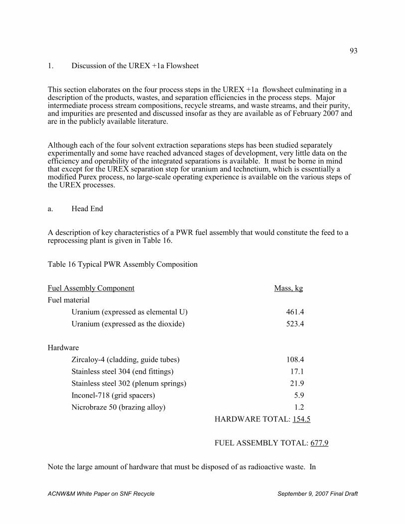
93
ACNW&M White Paper on SNF Recycle September 9, 2007 Final Draft
1. Discussion of the UREX +1a Flowsheet
This section elaborates on the four process steps in the UREX +1a flowsheet culminating in adescription of the products, wastes, and separation efficiencies in the process steps. Majorintermediate process stream compositions, recycle streams, and waste streams, and their purity,and impurities are presented and discussed insofar as they are available as of February 2007 andare in the publicly available literature.
Although each of the four solvent extraction separations steps has been studied separatelyexperimentally and some have reached advanced stages of development, very little data on theefficiency and operability of the integrated separations is available. It must be borne in mindthat except for the UREX separation step for uranium and technetium, which is essentially amodified Purex process, no large-scale operating experience is available on the various steps ofthe UREX processes.
a. Head End
A description of key characteristics of a PWR fuel assembly that would constitute the feed to areprocessing plant is given in Table 16.
Table 16 Typical PWR Assembly Composition
Fuel Assembly Component Mass, kg
Fuel material
Uranium (expressed as elemental U) 461.4
Uranium (expressed as the dioxide) 523.4
Hardware
Zircaloy-4 (cladding, guide tubes) 108.4
Stainless steel 304 (end fittings) 17.1
Stainless steel 302 (plenum springs) 21.9
Inconel-718 (grid spacers) 5.9
Nicrobraze 50 (brazing alloy) 1.2
HARDWARE TOTAL: 154.5
FUEL ASSEMBLY TOTAL: 677.9
Note the large amount of hardware that must be disposed of as radioactive waste. In
94
ACNW&M White Paper on SNF Recycle September 9, 2007 Final Draft
conventional reprocessing of spent LWR fuel in the head end step the spent fuel is removed fromthe storage area and segmented prior to dissolving it in nitric acid in the head-end hot cell. Theassembly may be broken down into individual fuel elements or sheared as a whole. Segmentation is typically done with a remotely operable shear that cuts the spent fuel elementsor assemblies into pieces one-to-two inches long. This permits ready access of the nitric aciddissolvent to the oxide fuel pellets in the cladding.
During fuel segmentation and dissolution, gases or volatile fission products trapped in the fuel orpresent in the plenum space at the ends of the fuel elements are released into the hot cell off-gassystem. The most important off-gas species from the point of view of waste management are 129I,85Kr, 3H, 14CO2. The Zircaloy cladding hulls will contain an appreciable fraction of the tritium(as much as 41 %) as zirconium hydride. Some volatile RuO4 may also be present in the off-gas. Although the radioactivity of Ru isotopes in aged spent fuel is low (1.851E-02 Ci/ MTIHM), thetotal mass of Ru is not negligible (8.691E+02 g/MTIHM). For this reason it deserves attentionbecause it may interfere with recovering the important off-gas species noted above. Because ofthe ease of reduction of the volatile RuO4 it may be removed from the off-gas by reduction andtrapping on steel wool filters which become a waste.
With the exception of iodine trapping processes many of the candidate processes potentiallyapplicable to reprocessing plants in the U.S. for trapping the other volatile fission products are inan early stage of engineering development and demonstration, although the technology ofsystems such as cryogenic are well known in other applications. Iodine trapping methodsinclude scrubbing the dissolver off-gas in KOH solution, or highly concentrated nitric acid andmercuric nitrate solution, or trapping on solid sorbents, principally those containing silver withwhich iodine reacts to form highly insoluble AgI or AgIO3. Sorption on charcoal has been used,but charcoal has significant drawbacks primarily due to its flammability. Only the very long-lived 129I iodine isotope (t1/2 = 1.57E+07 yrs) is of major consequence in spent fuel reprocessingbecause the other iodine isotopes are either very short-lived (131I: t1/2 = 8.02 days ) or stable. Asmall fraction of the iodine may remain in the dissolver solids as AgI and PdI2. This residue may be put into solution and subsequently into the off-gas by the addition of KIO3 to thedissolver, but this would require another process step.
The only krypton isotope of radiological importance in SNF reprocessing is 85Kr (t1/2 = 10.72yrs). Krypton removal has been studied using cryogenic distillation, sorption on zeolites andcharcoal, and selective sorption in various liquids such as dichlorodifluoromethane (a refrigerantnow out of favor because of its effect on the ozone layer). Diffusion through permselectivemembranes such as silicone rubber is also a candidate for krypton separation. Xe, which hasnegligible radioactivity in long-cooled fuel, has about 19 times the volume of krypton in the off-gas after 25 years decay. Both of these gases are chemically inert, and their physical propertiesare the basis of their separation from other gases. However, it is possible to separate kryptonfrom xenon and thus reduce the volume of radioactive rare gas stored.
Tritium, (t1/2 = 12.26 yrs) is a rare isotope in the natural environment. About two thirds of thetritium produced in LWR fuels is from ternary fission and one third from neutron activation. During aqueous reprocessing of spent LWR fuel any tritium that has not reacted with oxygen inthe fuel or escaped as gas in the head end step will react with water in the dissolver producingtritiated water, HTO. A promising method for controlling tritium during fuel reprocessing isvoloxidation [Goode, 1973a] which is described in more detail in Sect. VI.A.2.a. In voloxidation
95
23 The pertechnetate anion, TcO4-, is thought to form an extractable complex species with zirconium which upon
extraction releases the pertechnetate ion which then forms a complex species with the uranyl ion (UO22+) and
remains largely, but not entirely, with the uranium stream.
24 Notwithstanding the experience with incomplete extraction of Tc observed by others, in THORP it was found thatessentially all of the technetium extracted with the uranium. By changes in process chemistry it was possible to stripTc selectively from the uranium using high-acidity in a technetium contactor.
ACNW&M White Paper on SNF Recycle September 9, 2007 Final Draft
the tritium is vaporized from the spent fuel by heating in air or oxygen before spent fueldissolution in acid. The HTO thus formed may then be trapped in a dessicant such as silica gelor a zeolite. If tritium removal and containment is required for plant licensing, then voloxidationmay be the removal method of choice. If tritium is not removed before acid dissolution of thefuel, then it exchanges with hydrogen in the acid in the dissolver solution to produce tritiatedwater whose disposal path would be through evaporation. This may not be an acceptableapproach. In any case, the relatively short half-life of tritium means that after100 years it willhave decayed to a very low level of radioactivity.
Spent fuel contains 14C (t1/2 = 5.73E+03 years) primarily produced from the 14N (n,p)14C reactionwith the nitrogen that is typically present in the fuel at the 10-60 parts per million level. 14C isproduced at a rate of about 10-20 Ci/GWe/year of reactor fuel irradiation [Chopin, 1987]. Itsremoval is a straightforward operation in principle because the carbon will be present as 14CO2,which is readily sorbed in a large number of sorbents such as KOH, CaO and molecular sieves(zeolites).
From the above discussion it is apparent that because of their short half lives neither krypton nortritium is a long term hazard. Their storage for one hundred years would suffice to remove themfrom further concern. On the other hand, if capture and storage are imposed requirements foriodine and carbon, they will remain as long-term concerns. At present there are no generallyaccepted chemical forms or methods for their permanent disposal.
b. Central Unit Operations
i. UREX
The first step in the UREX+1a process is called simply UREX in this report. In the UREX stepof DOE’s UREX+1a process the uranium and technetium in solution23 are separated by solventextraction with tributylphosphate, typically as a 30% by volume solution in n-dodecane, from theother actinides, the lanthanides and the fission products. Technetium extracts along withzirconium as a complex species24. The addition of the reducing agent acetohydroxamic acid(AHA) in the process prevents the extraction of plutonium by reducing it to in-extractablePu(III). After being stripped into an aqueous stream with nitric acid the uranium is converted to oxide for storage and subsequent use or disposal. If the AHA is omitted in UREX it becomesessentially the PUREX process because the uranium and plutonium would be co-extracted inpurified form and can be readily separated.
The use of pulse columns for solvent extraction leads to process simplicity and reliability. However, centrifugal contactors can process a given amount of spent fuel faster and in a much
96
25 Although this delayed precipitation of noble metals has been observed in early work at ORNL, it has not beenobserved in THORP operations, even though it was specifically looked for.
ACNW&M White Paper on SNF Recycle September 9, 2007 Final Draft
smaller space at the cost of increased complexity and somewhat decreased reliability. Specifically, centrifugal contactors cannot tolerate “crud” accumulation because it tends to blockoverflow orifices. A small amount of solid noble metals have been observed to precipitateslowly from the dissolver solution25, and these could pose problems in a centrifugal contactor.
The volume of solid waste produced is related to the type of reagents used in reprocessing. Forexample, although the PUREX process uses tri-n-butyl phosphate (TBP), neither the TBP nor itsdegradation products can be converted entirely to gaseous products because of the presence ofthe phosphorus atom in the molecule. This can lead to a non-volatile solid waste.
The UREX+1a process removed the technetium from the acidic uranium product stream using anorganic anion exchange resin (Tc is present as the TcO4
- anion). The TcO4- anion is stripped
from the resin and precipitated as finely divided metal using an alkaline solution of sodiumborohydride or by reduction to metal in a furnace. After multiple uses and stripping to removeresidual Tc the anion exchange resin is carbonized, packaged, and shipped off-site for disposal. The technetium metal may be converted to a final waste form by combining it with the washedand compacted cladding hulls from the head-end dissolution step. Alternatively, it could becombined with the dissolver heal of noble metals sludge and disposed of with that waste.
ii. CCD-PEG
The raffinate from UREX contains the actinides Pu, Np, Am and Cm as well as the lanthanides,137Cs, 90Sr, and other fission products. The raffinate from UREX becomes the feed to processstep 2, the CCD-PEG process [CCD-PEG, 2003], [CCD-PEG, 2006], where the Cs and Sr areseparated from the actinides, lanthanides and fission products using a chlorinated cobaltdicarbollide-propylene glycol (CCD-PEG) solvent as extractant. The CCD-PEG process is mostefficient when the feed is < 1 M nitric acid so it can be used directly on the low-acidity UREXprocess step raffinate. The separated Cs and Sr may be solidified in several ways, including asstable alumino-silicate waste in a steam reforming process using an incorporated clay such askaolin to reduce the solubility of the Cs and Sr.
iii. TRUEX
The raffinate from process step 2 becomes the feed to process step 3, the TRUEX process[TRUEX, 1998], where the transuranic actinide and lanthanide elements are extracted from theremaining fission products using a TBP- carboxylmethylphosphine oxide (CMPO) in n-dodecaneextractant. The actinides and lanthanides are stripped from the extractant with lactic acid. Thestrip solution becomes the feed to the next and final UREX+1a process step.
iv. TALSPEAK
97
ACNW&M White Paper on SNF Recycle September 9, 2007 Final Draft
The strip solution (raffinate) from the TRUEX process containing the actinides and lanthanidesbecomes the feed to process step 4, the TALSPEAK process, where, after feed adjustment, thelanthanides are extracted from the actinides [TALSPEAK, 1964], [TALSPEAK, 1999]. TheTALSPEAK process performs the difficult separation of actinides and lanthanides, whosechemistries are very similar. This solvent extraction separation process is carried out using Di-2-ethylhexylphosphoric acid (HDEHP) in n-dodecane as extractant, with lactic acid anddiethylenetriaminepentaacetic acid (DTPA) as complexants and concentrated nitric acid as astripping agent. Very careful control of pH at about pH 3 and careful control of organic-to-aqueous process stream phase ratios are required to effect the desired separation.
The TALSPEAK process relies on the difference in the strengths of the respective complexesformed by the lanthanides and the actinides with DTPA to achieve their separation. The DTPAcomplexes are not extracted. Because a much smaller fraction of the lanthanides are complexed,a larger fraction of them is extracted by the HDEHP.
The following chemical reaction shows the strong dependence on pH of complex formation withDTPA.
M n+ + H5DTPA –> MDTPA (5-n) - + (5-n) H+
Here M represents the actinide or lanthanide ion, n is the valence of the species involved, and His hydrogen in the reaction. From this equation it is apparent that for trivalent ions there is asquare dependence on the hydrogen ion concentration. Thus, if the pH goes from 3 to 4, i.e., if it changes a factor of 10, the equilibrium shifts a factor of 100 to the left, assuming all else staysthe same. This helps explain the exceptional sensitivity of the TALSPEAK process on pH.
v. Products and wastes
The transuranic elements are in the raffinate from the TALSPEAK extraction cycle. They are tobe solidified, possibly in combination with some of the uranium, packaged, and stored untilshipment off-site for subsequent refabrication into fuel for transmutation. The lanthanides andresidual fission products are in the strip stream and are solidified, packaged, and stored until thetime of final disposal.
The lanthanides (also called rare earths) are the radionuclides selected by both the UREXprocesses and the French GANEX (see Sect. V.D.) process for separation from the actinidesbecause of their interference with efficient recycle and reuse of the actinides.
Cesium and strontium wastes are to be put into a stable chemical form and stored for theireventual decay to levels acceptable for near-surface disposal. In this scenario it will benecessary to provide monitored storage space for the cesium and strontium for an extended time.
It is noted that a small amount of fluoride (~0.01 M) is used in the dissolution step because after
98
ACNW&M White Paper on SNF Recycle September 9, 2007 Final Draft
fuel dissolution the acidity is reduced during feed adjustment to the point that fluoride ion isneeded to prevent hydrolysis (through complexation) of some of the radionuclides. Althoughnot listed in the flowsheets, fluoride ion appears in the feed and the raffinate streams in all theprocess steps. Fluoride ion can exacerbate corrosion, especially in equipment like the dissolverand the waste vitrifier.
2. Process assumptions for modeling the UREX +1a flowsheet
In order to calculate the distribution of radionuclides among the waste and product streams it isnecessary to make some assumptions about separation factors achieved in the process steps. There has been considerable experience in reprocessing, and some separation factors are knownfor common processes like PUREX. However, the major spent fuel reprocessors, e.g., Franceand the UK, consider the separation factors to be proprietary information. There are, however,certain limits on the concentration of radioisotopes in wastes that are specified in the U.S. Codeof Federal Regulations or consensus product specifications. In the absence of data on separationfactors, these limits may be used as criteria that must be met, and thus as specifications for thewastes. Additionally, for some of the less common UREX+1a process steps, e.g., CCD-PEG,TRUEX, and TALSPEAK, there are publications that contain information from laboratoryexperiments or on limited plant experience that may be used to derive separation factors. All ofthese sources of information, along with information from burnup calculations made withORIGEN2 [Croff, 1980] and the judgment of the authors, was used to obtain the information inAppendix F.
The following sections discuss the most important product, effluent, and waste streams thatwould be produced by a reprocessing plant using a UREX+1a flowsheet.
a. Off-gas effluent stream
All plant operating areas have off-gas systems that capture the gases and vapors leaving the areaand treat them before they are vented to the atmosphere. In general, air flows from areas of lowradioactivity to areas of higher radioactivity to reduce contamination. Each vented radionuclidehas a different biological effect on the human body, and this must be taken into considerationwhen deciding what remediation action to take for that radionuclide. In general theradionuclides in the off-gas must be retained at least to the level of retention required by theregulations. These limits and technologies proposed to meet them and to retain the radionuclidesfor storage and disposal have been discussed [ANL, 1983; DOE, 1986; Goode 1973 a,b; IAEA1980, 1987, 2004; Wigeland 2007].
The most important reprocessing off-gas streams are those from the spent fuel shear and thedissolver. It is these streams that contain the bulk of the radioactive gases and vapors (tritium,krypton, iodine, carbon dioxide, ruthenium, particulates and aerosols) as well as hazardouschemical species (nitrogen oxides). Other important off-gas streams are those from the fissionproduct and lanthanide waste calcination (if used) and vitrification steps, which are notexamined in this paper. Numerous specific technologies can be used to remove these speciesfrom off-gas streams. The sequence of and description of processes selected here is taken from[IAEA, 2004] for tritium and 14C is as follows:
99
26The significant radioactive isotope of ruthenium (mass number = 106, half-life = 1 year) is only relevant in fuelsaged less than ~10 years before reprocessing, which will not be the case in the U.S. for many years. However, non-radioactive ruthenium removal may still be needed to prevent clogging the off-gas system.
ACNW&M White Paper on SNF Recycle September 9, 2007 Final Draft
• Tritium: To be effective recovery of tritium must occur before the spent fuel encounterssubstantial amounts of water such as the dissolver solution to prevent isotopic dilution ofthe tritium with large amounts of 1H in water. As a consequence, tritium removal andrecovery occurs immediately after the spent fuel is chopped (sheared) into segmentsusing the voloxidation (volume oxidation) process. This process depends on theoxidation of the UO2 spent fuel matrix to lower-density U3O8 in order to break down thefuel matrix crystal lattice and release trapped gases from it. Voloxidation is unlikely tobe effective with thorium-based fuels because thorium does not have a higher valencestate to which it can be oxidized. Voloxidation is implemented by heating the spent fuelsegments to 450 – 500 NC for several hours in a rotary kiln. The tritium in the evolvedgas is passed through a catalytic converter to yield tritiated water which is then removedfrom the off-gas by solid dessicants. Essentially all of the tritium is released from thespent fuel (but not necessarily from the Zircaloy hulls) and much smaller fractions ofother volatile species are released as well. If dehumidified oxygen is used in the kilnthen the recovered tritium will be very concentrated. To the extent humidity isintroduced the tritium will be diluted and the volume of the tritium waste form increased.
Development of voloxidation had largely ceased for about two decades at the end of the1970s. However, DOE is now supporting work in the U.S. and South Korea to furtherdevelop voloxidation, and this is supplemented by South Korea’s collaborative effortwith Canada to develop the DUPIC process (see Sect. III.A.2.g). The goal is to maintainthe high release rates for tritium while increasing release rates of other volatile species. Variations being examined include use of temperatures up to ~800 NC, use of somecombination of air, ozone and steam to oxidize the fuel, and cycling between oxidizingconditions and reducing conditions imposed by hydrogen gas in the voloxidizer.
Important open technical issues concerning voloxidation are the extent to which tritium isevolved from zirconium tritide formed in the Zircaloy cladding during voloxidation andthe extent to which other volatile species will be evolved from the fuel matrix. Also, theeffectiveness of voloxidation on fuels containing high concentrations of TRU elementssuch as those that might be used in a transmutation reactor is largely unknown.
• Iodine, Ruthenium, Aerosol, Particulates, and Nitrogen Oxides: After voloxidation thespent fuel segments are loaded into a dissolver containing concentrated nitric acid whichresults in evolution of the other volatile radioactive and hazardous species listed aboveinto the off-gas from the dissolver vessel. The next step in treating the off-gas is toremove aerosols and particulates, nitrogen oxides, ruthenium, 129I, and then more nitrogenoxides in that order. This is accomplished by passing the off-gas through a waterscrubber and de-entrainer to remove most of the nitrogen oxides as well as aerosols andsome particulates. The off-gas is then heated above its dew point, passed through a silicagel bed to absorb ruthenium26 and a HEPA filter for additional particulate removal. Theoff-gas stream is passed through sequential beds of silver zeolite to remove iodine. Although iodine decontamination factors of greater than 99.5% have been achieved[Davidson, 2007], it has not yet been shown that large reprocessing plants in the U.S. will
100
27The THORP is achieving an iodine decontamination factor of > 99.5% but it is primarily relying on causticscrubbing which is unlikely to be used in the U.S. unless it is released to the sea.
ACNW&M White Paper on SNF Recycle September 9, 2007 Final Draft
actually be able to achieve this performance using the proposed processes.27 Finally, theoff-gas is further heated, mixed with ammonia injected into the waste stream, and passedthrough a zeolite bed which decomposes the residual nitrogen oxides and ammonia tonitrogen and water.
Alternative iodine removal technologies have been developed and demonstrated or usedin small-scale plants. The advantages and disadvantages of various iodine removalprocesses are discussed in [DOE, 1986] and [IAEA, 1987]
• Carbon-14: The off-gas from the iodine removal step flows through two molecular sievebeds connected in series for water removal followed by two zeolite beds connected inseries for CO2 removal. Water is removed from the sieves by reducing the pressure. Asimilar approach is used for the zeolite beds containing the 14CO2. The resultingconcentrated carbon dioxide stream is routed to a scrubber where it bubbles through asaturated solution of CaOH2 to form insoluble calcium carbonate containing the 14C. Thecalcium carbonate is recovered using a vacuum filter, dried, and stabilized in drums.
• Krypton-85: The off-gas feed stream to the krypton recovery system consists primarily ofair with small amounts of water, nitrogen oxides, radioactive krypton, and stable xenon. The oxygen in the air is removed by reacting it with hydrogen in a catalytic recombiner. The gas is refrigerated to condense some additional water and then passed through silicagel for final water removal. The off-gas then enters a cryogenic absorption, stripping,distillation, and recovery process. Liquid nitrogen is the primary working fluid to enrichthe krypton concentration relative to that of xenon from about 7% at the outset to about80% in the product. The krypton-xenon product is then packaged for disposal. Moreinformation on krypton management can be found in [IAEA, 1980].
• Particulates: The final off-gas treatment step is additional HEPA filtration to removeremaining particulates and aerosols.
b. Technetium stream
Because of the importance of technetium as a long-term contributor to dose if it reaches thebiosphere it is important to decide how it should be managed. It is not clear how completely itwill be recovered in the UREX processes because it does not extract quantitatively with theuranium in the first process step. Also, as much as 15 % of it may become part of a noble metal(e.g, Pd, Ru, Rh, Pt) sludge in the spent fuel dissolver, in which case that portion could bemanaged differently than combining it with the cladding hulls as is shown in the UREX +1aflowsheet. The answer to these questions must await more definitive experimental informationobtained from an integrated engineering flowsheet demonstration and optimization. It should benoted that foreign reprocessors, e.g., the UK in their THORP plant, appear to have found a wayto make the dissolved Tc extract quantitatively with the uranium product which may facilitate itsseparation and subsequent management (see Sect. III.A.3.g).
101
28 Although the 137Cs itself is not an important source of radioactivity (beta rays of <40 Kev), 92 % of it decays to137mBa which decays with a half-life of 2.55 minutes; 90% of the 137mBa decays to yield a 0.662 Mev gamma ray,which is the source of penetrating radiation.
ACNW&M White Paper on SNF Recycle September 9, 2007 Final Draft
c. Uranium product stream
The uranium product stream contains 2097 tonnes of uranium (as uranyl nitrate) annually from a2200 MTIHM/year reprocessing plant. There will need to be a substantial uranyl nitratedenitration system to convert the liquid uranyl nitrate to solid uranium oxide. Denitration willproduce nitrogen oxides which must be recovered to prevent escape of toxic NOx gases to theatmosphere. There is also the option of making nitric acid from the oxides.
d. Solvent waste streams
There will be enough radioactivity in the solvent wastes streams to require care in their disposal.
As noted earlier, each UREX process step has a different solvent, probably requiring a differentsolvent waste cleanup system for each solvent. As the solvents need to be replaced, solventwaste streams will be produced. It is possible that incineration may be an acceptable means fortreatment of most of them because almost all the solvents are organic compounds. However,UREX and TALSPEAK process steps contain solvents (i.e., TBP and HDEHP) that cannot becompletely oxidized to gaseous compounds.
e. Fission product stream
The fission product waste stream, as the term is defined in this paper, contains all the fissionproducts except cesium, strontium, technetium, iodine, krypton, tritium, and carbon. Thesewastes are primarily the lanthanides and are the remaining wastes to be vitrified, packaged,stored and ultimately sent to a deep geologic repository.
f. Cs/Sr stream
137Cs and 90Sr pose a special and significant waste management problem. Together they are amajor short-term heat producer (see Appendix F and the graph in Appendix B), because theyaccount for more heat and more radioactivity than all the other radionuclides for several decades. 137Cs is a source of penetrating radiation28 and merits special attention. It is apparent that thecesium and strontium comprise a major waste management problem. The Cs/Sr is to be fixed ina chemically stable waste form, packaged, stored for about 300 years for to allow it to decay toless-than-Class C concentrations, and then disposed of in place.
g. Actinide Stream
The actinides are the principal useful product of the reprocessing plant as well as being aprinciple heat source (see Appendix F and the graph in Appendix B.) About 27.7 tonnes per
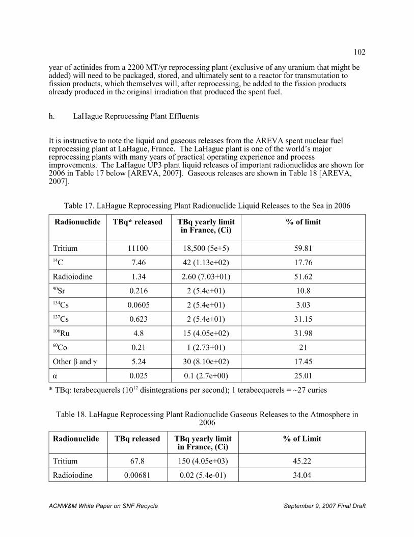
102
ACNW&M White Paper on SNF Recycle September 9, 2007 Final Draft
year of actinides from a 2200 MT/yr reprocessing plant (exclusive of any uranium that might beadded) will need to be packaged, stored, and ultimately sent to a reactor for transmutation tofission products, which themselves will, after reprocessing, be added to the fission productsalready produced in the original irradiation that produced the spent fuel.
h. LaHague Reprocessing Plant Effluents
It is instructive to note the liquid and gaseous releases from the AREVA spent nuclear fuelreprocessing plant at LaHague, France. The LaHague plant is one of the world’s majorreprocessing plants with many years of practical operating experience and processimprovements. The LaHague UP3 plant liquid releases of important radionuclides are shown for2006 in Table 17 below [AREVA, 2007]. Gaseous releases are shown in Table 18 [AREVA,2007].
Table 17. LaHague Reprocessing Plant Radionuclide Liquid Releases to the Sea in 2006
Radionuclide TBq* released TBq yearly limitin France, (Ci)
% of limit
Tritium 11100 18,500 (5e+5) 59.8114C 7.46 42 (1.13e+02) 17.76
Radioiodine 1.34 2.60 (7.03+01) 51.6290Sr 0.216 2 (5.4e+01) 10.8134Cs 0.0605 2 (5.4e+01) 3.03137Cs 0.623 2 (5.4e+01) 31.15106Ru 4.8 15 (4.05e+02) 31.9860Co 0.21 1 (2.73+01) 21
Other β and γ 5.24 30 (8.10e+02) 17.45
α 0.025 0.1 (2.7e+00) 25.01
* TBq: terabecquerels (1012 disintegrations per second); 1 terabecquerels = ~27 curies
Table 18. LaHague Reprocessing Plant Radionuclide Gaseous Releases to the Atmosphere in2006
Radionuclide TBq released TBq yearly limitin France, (Ci)
% of Limit
Tritium 67.8 150 (4.05e+03) 45.22
Radioiodine 0.00681 0.02 (5.4e-01) 34.04
103
ACNW&M White Paper on SNF Recycle September 9, 2007 Final Draft
Noble gases 242000 470,000(1.27e+07)
51.58
14C 14.2 28 (7.56e+02) 50.7
Other β and γ 0.000106 0.0010 (2.7e-02) 10.6
α 0 0.00001 (2.7e-04) 17.3
From the above tables it is apparent that all releases from La Hague reprocessing are less thanallowable release limits in France. Additionally, radionuclide releases from the LaHague plantto the atmosphere are in general much less than those to aqueous discharges from the plant. 14C,which is released as CO2 and is a soft beta emitter, is an exception. The noble gases have shorthalf lives and are not biologically active.
3. Quantitative Analysis of UREX +1a Waste and Product Stream Characteristics
The purpose of this section is to provide the results of an illustrative calculation of the typicalradioactive and physical properties of the waste and product streams from the UREX+1aflowsheet. The purpose of such calculations is to approximate the characteristics of typicalUREX+1a wastes as a basis evaluating what needs to be done to develop an appropriateregulatory framework for recycle facilities. Such calculations are based on a large number ofassumptions concerning, for example, the age and burnup of the SNF fed to the process,separation factors for key radionuclides for each step in the process, and the chemical form,stabilization matrix, loading, and density of the final product or waste forms.
The burnup distribution of the spent LWR fuel in 1999 as a function of age is shown in Fig 19[Kouts, 2007]. As is evident, the age and burnup cover a wide range. Adjusting the agedistribution for time elapsed since 1999 leads to the average age of SNF currently in storagebeing about 25 years. Reprocessing SNF would slow or reverse the trend of increasing SNF agedepending on whether SNF were to be reprocessed at a greater rate than it was being produced. However, the likely initiation of reprocessing at least a decade away which will make theaverage feedstock commensurately older. Additionally, with SNF being produced at a rate of2100 MT per year it would take the equivalent of three large (~800 MT per year throughput)SNF reprocessing plants just to stabilize the aging of the SNF inventory. Achieving thisthroughput appears to be some distance in the future because DOE has stated that the throughputof the CFTC should be “able to be increased to approximately 2,000 to 3,000 metric tons peryear to support commercial operation.” [DOE, 2006a]. In a notice requesting expressions ofinterest in the CFTC [DOE, 2006b] the U.S. Department of Energy implies that the initialthroughput will have a value below this range.
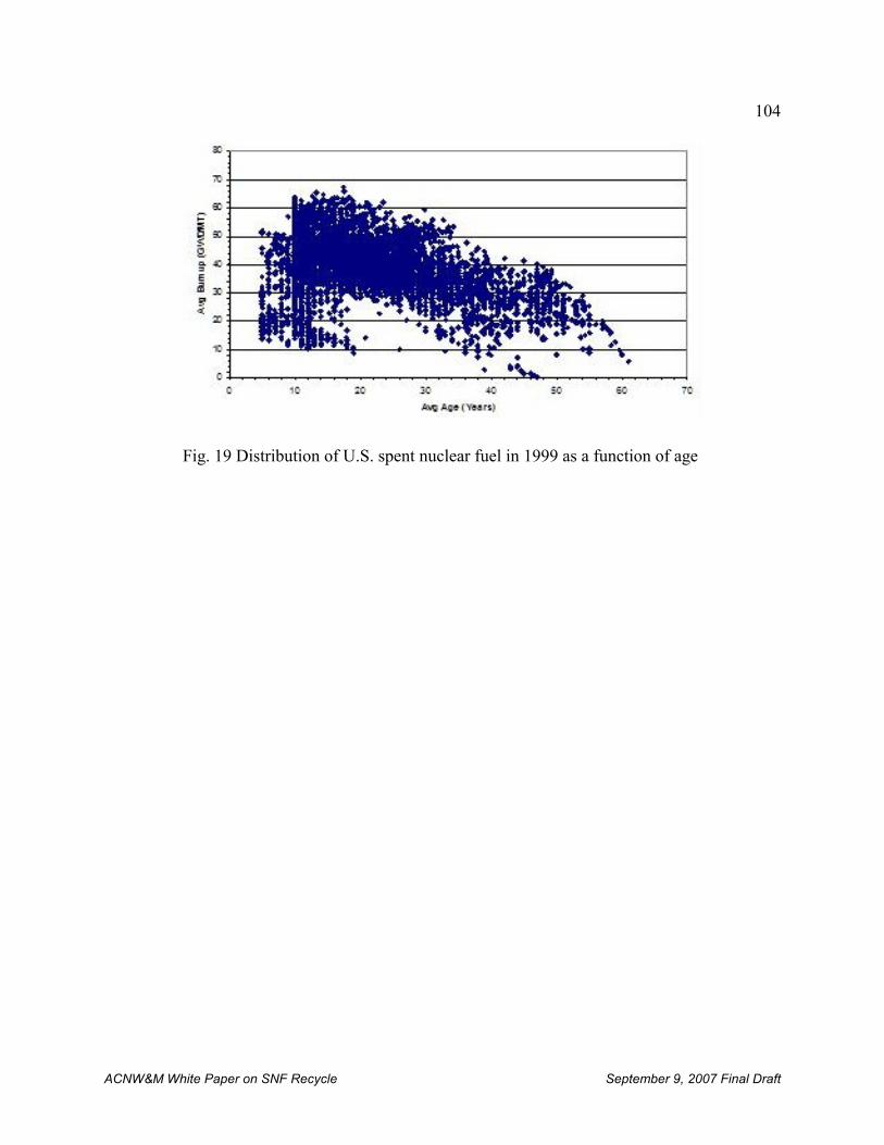
104
ACNW&M White Paper on SNF Recycle September 9, 2007 Final Draft
Fig. 19 Distribution of U.S. spent nuclear fuel in 1999 as a function of age
105
ACNW&M White Paper on SNF Recycle September 9, 2007 Final Draft
The average burnup of stored LWR SNF at the end of 1998 was 30.4 GWd/MT and at the end of2002 (the latest report) this had increased to 33.6 GWd/MT [EIA, 2004]. The trend ofincreasing burnup seems likely to continue as utilities seek to get more energy out of their fuel,although high uranium or enrichment costs could mitigate the trend.
On balance, a burnup of 33 GWd/MT has been selected because this value is close to the currentaverage burnup. Additionally, this assumption was efficient and facilitated verification ofcalculated results by allowing the use of existing PWR models for which published results wereavailable. Given the speculative nature of assumptions concerning when reprocessing mightensue and the rate at which capacity will be built, a SNF age of 25 years was selected.
In order to calculate the waste compositions and characteristics it was necessary to use values forseparation factors of the various radionuclides in the process steps as well as waste formdensities and loadings. In most cases reliable values for separation factors from plant operatingdata are not available. These are usually considered to be proprietary by plant operators,although some data from early reprocessing have been published. There are also some datareported in the early literature and data from laboratory experiments using fully irradiated fuelfor processes like CCD-PEG, TRUEX and TALSPEAK. However, the entire UREX+1aflowsheet has not been demonstrated on SNF at a scale that provides a foundation forassumptions concerning separation factors. Regarding parameters concerning waste formcharacteristics, in many cases fundamental decisions (e.g., which waste form will be used) havenot been made. Based on evaluation of the results of UREX+1a experiments performed to-dateand the historical and current literature concerning waste forms by independent experts, theassumed parameters in Appendix F were assembled. Values in Appendix F were used tocalculate the waste stream compositions amounts using ORIGEN2. The results of thesecalculations are given in Table 19.
During review many comments indicated the desire for additional detail on the composition ofinternal plant streams that might be important to safety. While the quest for such data isunderstandable, the UREX+1a flowsheet is not yet sufficiently mature to allow suchcompositions to be determined. Additionally, such information is likely to be deemed sensitiveand/or proprietary and could not be included in a public document such as this. As aconsequence, no information has been included at this level of detail.
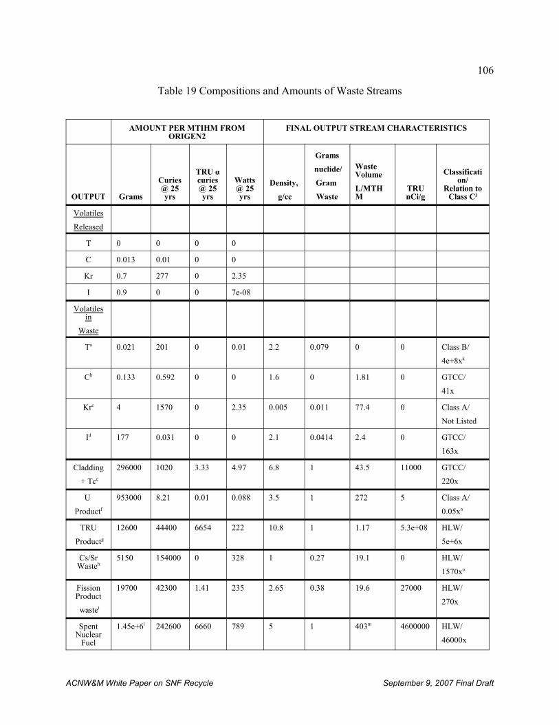
106
ACNW&M White Paper on SNF Recycle September 9, 2007 Final Draft
Table 19 Compositions and Amounts of Waste Streams
AMOUNT PER MTIHM FROMORIGEN2
FINAL OUTPUT STREAM CHARACTERISTICS
OUTPUT Grams
Curies@ 25yrs
TRU αcuries@ 25yrs
Watts@ 25yrs
Density,
g/cc
Grams
nuclide/
Gram
Waste
WasteVolume
L/MTHM
TRUnCi/g
Classification/
Relation toClass Cj
Volatiles
Released
T 0 0 0 0
C 0.013 0.01 0 0
Kr 0.7 277 0 2.35
I 0.9 0 0 7e-08
Volatilesin
Waste
Ta 0.021 201 0 0.01 2.2 0.079 0 0 Class B/
4e+8xk
Cb 0.133 0.592 0 0 1.6 0 1.81 0 GTCC/
41x
Krc 4 1570 0 2.35 0.005 0.011 77.4 0 Class A/
Not Listed
Id 177 0.031 0 0 2.1 0.0414 2.4 0 GTCC/
163x
Cladding
+ Tce
296000 1020 3.33 4.97 6.8 1 43.5 11000 GTCC/
220x
U
Productf
953000 8.21 0.01 0.088 3.5 1 272 5 Class A/
0.05xn
TRU
Productg
12600 44400 6654 222 10.8 1 1.17 5.3e+08 HLW/
5e+6x
Cs/SrWasteh
5150 154000 0 328 1 0.27 19.1 0 HLW/
1570xo
FissionProduct
wastei
19700 42300 1.41 235 2.65 0.38 19.6 27000 HLW/
270x
SpentNuclear
Fuel
1.45e+6l 242600 6660 789 5 1 403m 4600000 HLW/
46000x
107
ACNW&M White Paper on SNF Recycle September 9, 2007 Final Draft
atritiated water in polymer-impregnated cementbCalcium carbonate in cementcCompressed gas in cylinderdGrouted silver zeoliteeHomogeneous alloy of structural material, dissolver solids, Tc, and some undissolved fuelfUranium oxide having concentrations of other radionuclides suitably low to allow re-enrichmentgOxides of the various elements sintered to 95% of theoretical densityhGlass-bonded aluminosilicate made by steam reformingiVitrified into borosilicate glass logsjApparent waste classification/ratio of sum-of-the fractions for material to Class C limits if material is declared to be wastekAssumes no dilution of tritium with hydrogen isotopes other than those produced in the fuel matrixlIncludes oxygen associated with fuel matrixmVolume of a single intact PWR SNF assembly (21.4 cm x 21.4 cm x 406 cm) normalized to 1.0 MTHM. Volume of an intactassembly in a canister would be 635 L/MTHM.nAssumes that recycle uranium specifications are met for TRU and that Tc concentrations are typical of THORP experience (0.03ppmw). TRU element concentration can increase about two-fold before Class C levels are reached and about twenty-fold beforethe uranium would be GTCC.oWaste is HLW because it is derived from the first cycle raffinate unless DOE determines it is waste incidental to reprocessing.
The following sections will discuss waste-specific aspects of Table 19. One generic aspect ofTable 19 concerns deciding which materials would be HLW if they were declared to be waste. The current definition of HLW [NWPA, 1996] is:
“The term “high-level radioactive waste” means –
(1) the highly radioactive material resulting from the reprocessing of spentnuclear fuel, including liquid waste produced directly in reprocessing andany solid material derived from such liquid waste that contains fissionproducts in sufficient concentrations; and
(2) other highly radioactive material that the Commission, consistent withexisting law, determines by rule requires permanent isolation.”
Key terms such as “highly radioactive” and “fission products in sufficient concentrations” havenot been further elaborated. Additionally, the Commission has not identified any “other highlyradioactive material” that requires permanent isolation. The preceding definition has beeninterpreted in 10 CFR 50, Appendix F as follows:
“ . . .‘‘high-level liquid radioactive wastes’’ means those aqueous wastes resultingfrom the operation of the first cycle solvent extraction system, or equivalent, andthe concentrated wastes from subsequent extraction cycles, or equivalent, in afacility for reprocessing irradiated reactor fuels.”
Conventionally, HLW has been taken to include the raffinate from the first cycle of solventextraction in a Purex facility. This would include essentially all of the non-volatile fission
108
ACNW&M White Paper on SNF Recycle September 9, 2007 Final Draft
products, Np, Am, and Cm plus a small fraction of the U and Pu. High-level waste would notinclude cladding and other fuel assembly structural materials or volatile species because theseare removed before the first solvent extraction cycle. Additionally, HLW would not includeorganic wastes (e.g., spent solvents) or aqueous wastes from subsequent solvent extractioncycles such as those used to purify the uranium product. Despite the potential exclusion ofaqueous waste from subsequent solvent extraction cycles from being classified as HLW,historical designs for Purex reprocessing plants have typically found it convenient to concentratesome of the more active waste streams from parts of the reprocessing plant other than the firstsolvent extraction cycle and combine them with the aqueous waste from the first cycle of solventextraction and manage them all as HLW.
The existing definition of HLW was not conceived with the UREX flowsheets in mind. Inparticular, part of the UREX+1a product (the transuranic actinide elements) is initially in theaqueous waste from the first cycle of solvent extraction and only becomes a separate productstream after going through three subsequent solvent extraction processes. Additionally,separation of Cs/Sr from the aqueous waste from the first cycle of solvent extraction raises thequestion of whether the separated Cs/Sr is HLW. Based on historical and recent (e.g.,concerning “waste incidental to reprocessing”) interpretations of what constitutes HLW, thispaper assumes that any material contained in the aqueous stream from the first cycle of solventextraction that is declared to be waste would be classified as HLW whether it has been separatedfrom the aqueous stream in subsequent processes or not. This assumption is reflected in therightmost column of Table 19.
a. Volatiles in Waste
Although waste forms for tritium, 14CO2 and 85Kr are shown here, these radionuclides have notbeen sequestered previously because no standards have been in place specifying their type ofretention. Consequently, these waste forms are the author’s judgment of what might constitutecredible waste forms.
Because 129I concentrates in the thyroid gland where, in sufficient amount, it may cause seriousdamage, especially in children, its sequestration has been required from the beginning ofreprocessing. Care is required to ensure its complete release into the off-gas during spent fueldissolution [CEA, 2007]. It is an especially troublesome radionuclide to dispose of as wastebecause it has few highly stable chemical compounds. Fixation of the silver zeolite sorbentcontaining the iodine was chosen in the present study because the system is inorganic andtherefore less subject to radiation damage than organic materials, AgI is insoluble under mostconditions likely to be found in the environment, and AgI is stable to relatively hightemperatures (It decomposes at its melting point of 552 °C.). Because it is a halogen it iscorrosive in the elemental form.
The following information elaborates on issues related to the classification of waste formscontaining volatile radionuclides:
• Tritium: Tritium is recovered by voloxidation before encountering the first aqueoussolutions in the reprocessing plant. It is assumed to be diluted by only the very small
109
ACNW&M White Paper on SNF Recycle September 9, 2007 Final Draft
amounts of 1H and deuterium produced by nuclear reactions in the fuel matrix. Thepossibility of dilution by water in air used to oxidize the fuel in the voloxidation step wasnot taken into account because the amount of humidity and air are design-specific. Theseassumptions lead to a very high tritium concentration in a very small volume of waste.
• Carbon-14: Dilution with stable carbon isotopes in the fuel matrix and some naturalcarbon in the plant off-gas was taken into account, but the very small volume of thewaste results in 14C concentrations exceeding Class C limits.
• Krypton-85: Krypton-85 is not listed in the tables in 10 CFR Part 61 so it is Class A bydefinition. Such classification deserves further evaluation because the half life of 85Kr issimilar to that of tritium, but 85Kr is more difficult to stabilize and has significantpenetrating radiation.
• Iodine-129: Again, the relatively small volume of the waste leads to a high concentrationof iodine in the waste form and classification as GTCC.
b. Cladding, Technetium, and Dissolver Solids
The cladding and Tc wastes may also contain the so-called noble metals Pt, Pd, Rh, Ru and Mothat constitute the dissolver solids. These noble metals may or may not be combined with thecladding hulls. If they are not removed from the dissolver with the cladding hulls then they willbe left in the dissolver and may be carried into the UREX process step. Together they present apotential problem in that, being solids, they may cause hot spots in the dissolver andsubsequently in the centrifuge used to clarify the feed to the solvent extraction equipment. Ifthey get beyond the feed clarification step they may cause problems in the centrifugal solventextraction contactors. A particular problem is potential blocking of the organic overflow weirs. The dissolver solids problem is further exacerbated by the fact that small amounts of solids havebeen observed to continue precipitating from the dissolver solution for up to two weeks as notedin Section VI.A.1.b.i (however, see footnote 23.). Further, if carried into the UREX process stepthe solids would add to the radiation damage to the solvent. The amount that slowly precipitateswas observed by ORNL investigators to be as much as 10 % of the amount that remains initiallyundissolved in the dissolver.
The cladding waste, which is assumed to contain most of the 99Tc and the dissolver solids (whichcontain a significant fraction of 129I), exceeds the Class C limit by a factor of 220 and isclassified as GTCC. The primary contributors to exceeding the Class C limit are TRU elementsand 99Tc, both of which exceed the Class C limit by about a factor of 100. 94Nb exceeds Class Climits by about a factor of 10. 59Ni and 14C are close to the Class C limit (0.5 and 0.3,respectively), and might exceed the limit for very high burnup fuels.
c. Uranium Product
The uranium may go any of several different disposition paths. DOE’s plans call for beneficial
110
ACNW&M White Paper on SNF Recycle September 9, 2007 Final Draft
use of the uranium by being combined with the actinide stream for use in the burner reactor orbeing re-enriched to produce LWR fuel. Some portion of the uranium may not find a beneficialuse in which case it would be converted to an oxide and managed as a waste much like DOE’scurrent approach to disposition of enrichment plant tails.
It should be noted that recycled uranium is not as benign as natural uranium for two reasons. First, no separation process is perfect and the uranium will contain trace amounts ofradionuclides such as 99Tc and 237Np. These radionuclides can become concentrated inenrichment facilities and have been troublesome in the gaseous diffusion plants because theytend to deposit on internal surfaces. Such deposits can complicate maintenance activities to thepoint that gaseous diffusion plant operators have been reluctant to contaminate their plants withrecycle uranium or have dedicated certain plants to recycle uranium enrichment. The currenttrend away from gaseous diffusion and toward gas centrifuge enrichment makes it much moreeconomic to dedicate part of the plant to recycle uranium.
The second difference between natural and recycle uranium is that the latter contains 236U and232U. The former is an undesirable neutron poison that detracts from the value of the recycleuranium. The latter is present in very small quantities (typically around 1 ppb) but it has arelatively short half-life (72y) and one of its decay products emits a very energetic gamma raywhich leads to higher occupational dose rates during fabrication than those from naturaluranium.
Based on the assumptions in Appendix F, the uranium product from reprocessing would be ClassA if it were declared to be waste. The major contributor to this (about 5% of Class C limits) isthe trace amount of transuranic elements assumed to accompany the uranium. It is important tonote that the assumption used in this paper is that the TRU elements are removed from recycleuranium to the point that it just meets applicable specifications for recycle. It is likely that theconcentration of TRU elements could be further reduced if required.
d. TRU Product
The TRU product stream from the TALSPEAK process is destined for transmutation. Itproduces about two-thirds as much heat as the Cs/Sr waste stream per MTIHM based on 25-year-old SNF and, as a consequence, requires packaging and storage in a way permittingcooling. Additionally, the alpha activity of this material is sufficiently concentrated so thatsignificant upstream (counter to ventilation air currents inside the facility) mobility of theactinides from alpha recoil can be expected and will need to be considered when designing theoff-gas system.
Under the assumption that materials separated from the aqueous raffinate from the first solventextraction cycle are HLW, if the TRU product were declared to be waste it would be HLW and,by concentrating the most toxic actinides into a small volume, would exceed Class C limits by alarge factor.
e. Cs/Sr Waste
111
ACNW&M White Paper on SNF Recycle September 9, 2007 Final Draft
137Cs is a difficult fission product to manage. The radioactivity of its short-lived 137mBa daughterproduces an energetic gamma ray and considerable concomitant heat. Consequently, packaging,storing, shielding and cooling will be significant problems for many decades. In addition, 135Cswhich has a long half-life (2.3E+06 yrs) is present in masses comparable to that of 137Cs after 25years of decay so the cesium waste package will require indefinitely long confinement.
The foregoing comment on heat production holds for 90Sr although its radiation is softer, andthere is no other long-lived Sr radionuclide present. The 90Y daughter is quickly in secularequilibrium, and decays with a very short half-life to stable 90Zr. Consequently, there may bemerit to adding an additional step to separate the Sr from the Cs to reduce the volume of wasteheld in long-term disposal although the UREX flowsheets do not do so.
Under the assumption that materials separated from the aqueous raffinate from the first solventextraction cycle are HLW, the Cs/Sr waste would be HLW unless DOE goes through the processto determine that it is not HLW. If the Cs/Sr were determined to not be HLW then they wouldbe GTCC waste because the concentrations of 90Sr and 137Cs initially exceed Class C limits by alarge factor. Current DOE plans call for this waste to be stored in some type of monitored near-surface engineered storage facility until it decays to Class C levels or lower at which time thefacility would be deemed to be a disposal facility. The combined 90Sr and 137Cs would decay toClass C limits in about 320 years. This disposal approach raises the issue of when the Cs/Srwaste would be classified: when it is produced at the reprocessing plant or after the extendedstorage period when the storage facility is converted to a disposal facility.
There is no limit for 135Cs in 10 CFR Part 61 and establishing such a limit might change itsclassification. However, the draft environmental impact statement for 10 CFR part 61 [NRC,1981] stated a limit of 84 mCi/L for 135Cs which is significantly larger than its concentration of18 mCi/L in SNF. An additional complication with the Cs/Sr waste is that cesium isotopesdecay to stable barium which would make the waste a mixed RCRA waste on the basis of thetoxicity characteristic of barium unless the waste form can be shown to release sufficiently smallamounts on barium in standard leach tests.
f. Fission Product Waste
The fission product waste, which in the present discussion does not include the gaseous andvolatile fission products or the Cs/Sr fission product waste, is destined for vitrification inborosilicate glass and eventual disposal in a geologic repository. The ultimate mass of fissionproduct waste would be that listed in Table 19 plus the mass of the TRU product that will befissioned in a transmutation reactor plus perhaps a few percent of the uranium mass if theuranium were to be re-enriched to produce LWR fuel.
The fission product waste is classified as HLW. It exceeds Class C limits by a factor of 270which is a much smaller factor than for the TRU product or Cs/Sr waste and is comparable to thecladding plus technetium waste. The residual TRU in this waste is the cause of exceeding theClass C limits.
112
ACNW&M White Paper on SNF Recycle September 9, 2007 Final Draft
g. Spent Nuclear Fuel Comparison
To provide some context for the foregoing discussion the characteristics of the PWR SNF thatproduced the foregoing wastes has been included. The following should be noted:
• The parameters in the left portion of the table (mass, radioactivity, and thermal power)are conserved so the values for the SNF are just the sum of the various wastes andproducts with minor differences from rounding. As a result of the intense radioactivityand thermal power of the TRU product (Am and Cm in particular) and Cs/Sr waste fromUREX, the waste destined for disposal in a deep geologic repository (cladding andfission product waste) are reduced to 18% and 30% of the amount in SNF. Thisreduction would not occur for a Purex process where the Cs/Sr, Am, and Cm remain withthe waste destined for deep geologic disposal.
• Assuming the uranium is reused, the waste volume from UREX+1a would be reduced byabout 79% as compared to SNF if the relatively voluminous 85Kr is excluded and by 59%if it is included. To the extent that uranium is not reused the volume of reprocessingwastes would be increased and in the limiting case the total waste volume would beincreased by about 8% as compared to SNF. In the case of a conventional Purex process,the volume of waste destined deep geologic repository disposal (~450 L/MTHM [Vernaz,2006]) is about the same as the volume of the parent SNF fuel (403 L/MTHM) per se andless than the volume of a SNF assembly in a canister (635 L/MTHM). This has beenaccomplished through careful management of facility operations, use of chemicals thatcan be degraded to water, nitrogen, and carbon dioxide, and the use of compactors andincinerators. However, to the extent that the uranium product is declared to be waste (upto 272 L/MTHM) or LLW destined for near-surface disposal (~200 L/MTHM) to thepoint that the total waste volume ranges from 1.45 to 2.3 times that of the SNF dependingon which SNF comparison basis is selected.
• The SNF assembly is about 46,000 times Class C limits. This factor is much less thanthe factor for the TRU product which is a reflection of concentrating the most hazardous10 CFR Part 61 species in the relatively small volume of the TRU product.
4. Potentially Toxic and Reactive Materials
In general the non-radiological hazards involved in spent nuclear fuel recycle will be regulatedby OSHA. The solvents used in the four UREX +1a process steps are commercially availableorganic compounds and as such require the same handling procedures in a reprocessing plant asare required for safely handling these somewhat toxic chemicals in industrial operations. Inordinary chemical process use none is extraordinarily toxic or reactive, although all pose somedanger to those who handle them. Other chemicals such as those used in solvent cleanup areinorganic compounds, and safe industrial practice should be observed. In cases where solventssuch as halogenated compounds are used the toxic halogens may be released by radiolyticdecomposition. Thus, although the compounds may be relatively benign in ordinary use, theycan become toxic in radiation environments. Nitric acid in a variety of concentrations is usedthroughout the process steps and because of its amounts and ubiquity it is probably the most
113
ACNW&M White Paper on SNF Recycle September 9, 2007 Final Draft
significant toxic chemical. There is a significant potential chemical hazard in the form of “redoil” which is discussed below.
a. Red Oil Explosions
Red oil is a substance formed when an organic extractant (in the first step of UREX the organicextractant is TBP) comes in contact with concentrated nitric acid (> 10 M) at a temperatureabove 120 EC. Contributory chemicals can include diluents (e.g, hydrocarbons used to diluteTBP) and/or aqueous phase metal nitrates. Red oil can decompose explosively when itstemperature is raised above 130EC. Three red oil explosions have occurred in the United States:one at the Hanford Site in 1953, and two at the Savannah River Site (SRS) in 1953 and 1975. Ared oil explosion also occurred in 1993 at the Tomsk-7 site at Seversk, Russia and in anevaporator in Canada. Equipment capable of producing red oil are evaporators and denitrators.
Controls for prevention or mitigation of a red oil explosion are generally temperature, pressure,mass, agitation of tank contents, and reactant concentrations. Maintaining a temperature of lessthan 60 EC is generally accepted as a means to prevent red oil explosions. Vessel venting servesto keep pressure from destroying the process vessel in the case of an explosion, while alsoproviding the means for evaporative cooling to keep red oil from reaching the runawaytemperature. Mass controls utilize decanters, hydrocyclones, and steam stripping to removeorganics from feed streams entering process equipment capable of producing red oil. Limitingthe total available TBP is another mass control that mitigates the consequence of a red oilexplosion by limiting its maximum available explosive energy. Washing the aqueous Pu and Uproducts with diluent to remove entrained TBP is effective in preventing red oil explosionsduring evaporation of these products. Finally, concentration control can be utilized to keep thenitric acid below 10 molar. A U.S. government study [DNFSB, 2003] concluded that none ofthe above controls should be used alone; rather, they should be used together to provide effectivedefense in depth for prevention of a red oil explosion. The operator of French reprocessingplants (AREVA) recently stated [ACNW&M , 2007] that red oil has not been observed in theirplants.
At present there is no information about the likelihood of forming red oil in UREX processes,although the first step that uses conventional TBP extraction may be expected to pose the samered oil risks as have been observed in the past.
b. Ion Exchange Resin Explosions
There have been nine documented incidents of fire, explosion, and/or vessel rupture in anionexchange vessels at the Savannah River Site that have been characterized as “resin explosions”[DNFSB, 2001]. They have occurred under various conditions of temperature and nitric acidconcentration. All of the systems involved were exchanging ions containing either plutonium,neptunium, curium, or uranium.
Conditions identified as contributing to a possible resin explosion are listed below:
• exposure of resin to greater than 9 molar nitric acid
114
ACNW&M White Paper on SNF Recycle September 9, 2007 Final Draft
• exposure of resin to high temperature
• allowing resin to dry
• exposure of resin to strong oxidants other than nitric acid, such as permanganate or
chromate ions
• exposure of resin to high radiation doses
• allowing resin to remain in a stagnant, non-flow condition while loaded with exchanged
metal and/or in contact with process concentrations of nitric acid
• exposure of resin to strong reducing agents, such as hydrazine
• exposure of resin to catalytic metals such as iron, copper, or chromium
By avoiding the above conditions it was possible to prevent further explosions, but great caremust be taken to prevent these explosions in the future, especially if separations involvingconcentrated Am/Cm are attempted.
B. Pyroprocessing
Pyroprocessing is a generic term for high-temperature reprocessing using pyrometallurgicalprocesses. There are many manifestations of pyroprocessing in the nuclear industry [NEA,2004], several of which are directed at spent fuel recycle. The DOE’s current plans call forpyroprocessing to be used to reprocessing the actinide product from UREX+1a after it had beenfabricated into metallic or possibly nitrite fuel elements and irradiated in a fast-spectrumtransmutation reactor.
Pyroprocesses are often carried out in fused salt systems in conjunction with electrometallurgicalsteps that remove uranium, plutonium, and other elements from the fused salt by electrolyticreduction onto a cathode. This leaves the fission products in the fused salt or in a moltencadmium pool, and is DOE’s currently planned pyroprocessing approach. Pyroprocess steps forseparating the Cs/Sr are not yet evident.
Pyroprocesses are not currently in significant use worldwide, but a great deal of research anddevelopment has been carried out on them. Electrometallurgical spent fuel reprocessing hasbeen studied and developed extensively at Argonne National Laboratory (ANL) for many years,and a fairly large-scale demonstration was carried out at DOE’s Idaho Falls facility usingExperimental Breeder Reactor (EBR-II) spent fuel.
The principles behind the electrometallurgical process are well understood, and no apparentinsurmountable technical barriers exist to their wider adoption [NAS, 2000]. An importantobstacle to widespread adoption of pyroprocessing is that reprocessing is currently being carriedout worldwide using aqueous processes and a very large experience base exists in large, well-established PUREX process plants. Consequently, there has been little demand forpyrometallurgical or other systems.
115
ACNW&M White Paper on SNF Recycle September 9, 2007 Final Draft
The feed to pyroprocessing was originally intended to be metallic spent fuel, and the processlends itself best to reprocessing this type of fuel. It is possible , however, to reprocess oxidefuels by first converting them to metal through a head end step that reduces the oxide to metal. This reduction is best accomplished using finely divided oxide, which can be prepared usingvoloxidation (see Sect. VI.A.2.a) to pulverize the oxide fuel. Process modifications are possiblethat separate uranium, plutonium and other actinides from the remainder of the radionuclides. Figures 20 and 21 are representations of two versions of the ANL pyroprocess. Note that inFigure 20 the cathodic product is uranium, whereas in Figure 21 the product is uranium plus thebulk of the actinides. Alterations in the details of operation of the system provide thecapabilities to tailor the product streams to the desired compositions, including essentially pureplutonium [Wymer, 1992].
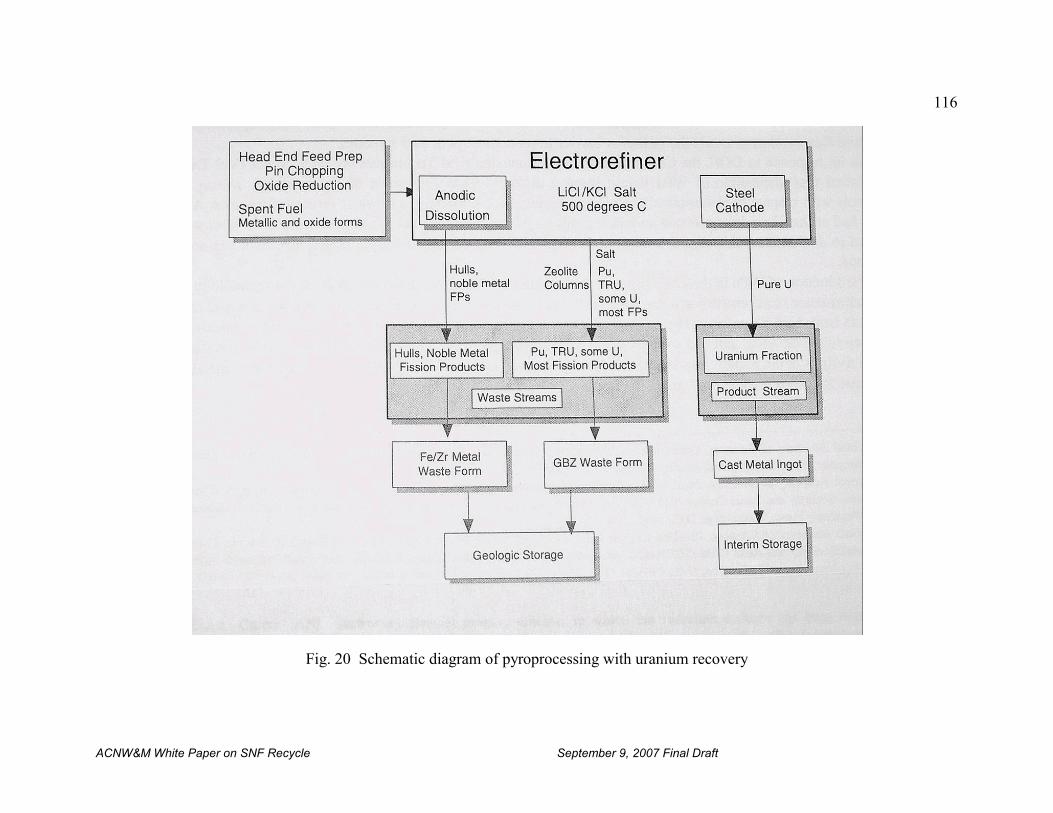
116
ACNW&M White Paper on SNF Recycle September 9, 2007 Final Draft
Fig. 20 Schematic diagram of pyroprocessing with uranium recovery
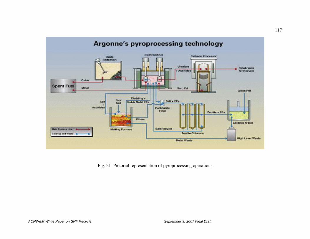
117
ACNW&M White Paper on SNF Recycle September 9, 2007 Final Draft
Fig. 21 Pictorial representation of pyroprocessing operations
118
ACNW&M White Paper on SNF Recycle September 9, 2007 Final Draft
Pyroprocessing bears no resemblance to the more conventional aqueous processes such asPUREX. Pyroprocessing is inherently a batch process. The size of the batches is limited by thenature of the electrorefiner, although it is possible to incorporate more than one electrorefiner ina single high-temperature unit and thus increase the throughput of the system. However, ingeneral, multiple electrorefiners would be required for commercial-scale reprocessing. Afterrepeated batch processes the salt accumulates impurities and must be discarded.
There are two major waste streams from this process: 1) the cladding hulls and the noble metalfission products that accumulate in the electrorefiner, and 2) small amounts of residual TRUelements and fission products. The cladding hulls are a relatively low activity solid waste. Thenoble metal fission products occur mostly as a metallic sludge, and could present a number ofproblems, both from the point of view of handling them and because they could cause electricalshort-circuiting problems. The residual TRU elements and fission products are sorbed on aglass-bonded zeolite (GBZ).
C. Reprocessing HTGR Fuels
High-Temperature Gas-Cooled Reactor (HTGR) fuels are distinctly different from other reactorfuels. This difference imposes a very different type of head-end processing. Unlike most otherreactors, the HTGR fuel is not a ceramic oxide fuel clad in metal tubing. HTGR fuel is mademostly of graphite, and is in one of two geometric configurations, the spherical (pebble) form,and the prismatic form mentioned above, both of which are unlike any other reactor fuels. (Seethe discussion of the composition of HTGR fuels in Sect. II.B.4) There has been no commercialreprocessing of HTGR fuels, although development work has been conducted at Oak RidgeNational Laboratory and elsewhere. Some of the salient features of HTGR fuel reprocessing arediscussed below.
1. Flowsheets
The first step in reprocessing HTGR fuels is removal of the bulk of the graphite, whether it is inthe form of balls or prismatic blocks [DeCul, 2002]. Several removal approaches have beenconsidered. The balls would be crushed or burned to release the TRISO particles, which containthe fuel material of interest. The crushed material would be sieved to recover the fuel particlesand the inert graphite would become a waste stream. The separated fuel particle would then beput through a grinder to break the TRISO coatings and release the tiny fuel kernels that containthe uranium and actinides and fission products. Finally, the crushed fuel material and anyresidual graphite would be dissolved in nitric acid preparatory to solvent extraction. Alternatively, the residual graphite could be burned either before or after crushing the fuel. Theadvantage to early removal of the graphite by crushing or burning is that it would remove thebulk of the graphite before dissolution in nitric acid. Nitric acid dissolution of finely groundgraphite and carbides produces organic compounds that could interfere with the solventextraction separation step, which is the next step in reprocessing. In any case the fragments ofthe silicon carbide inner coating would need to be removed before the solvent extraction stepbecause their presence could interfere with the operation of the solvent extraction equipment,especially if centrifugal contactors were used.
119
ACNW&M White Paper on SNF Recycle September 9, 2007 Final Draft
For the prismatic fuel blocks it is desirable to separate the coated microspheres from the bulk ofthe graphite block as a first head-end step. This might be done by burning as described above orreaming the carbonized fuel sticks out of the blocks. In this way the bulk of the graphite couldbe physically removed, leaving the coated microspheres for treatment as outlined above for thefuel balls. The de-fueled prismatic blocks could then be disposed of in the same way as is donefor managing graphite from reactors [IAEA, 2006], [Wickham, 1999] , i.e., by:
(I) permanent removal from the “environment” as solid graphite;
(ii) destruction, e.g. incineration; and,
(iii) re-cycling.
2. Unusual Plant Features
The head-end of the HTGR spent fuel reprocessing plant would have unique features arisingfrom the necessity to crush, grind, or burn the graphite fuels. These steps are to be contrastedwith the relatively much simpler fuel shearing employed with LWR fuels. After these head-endsteps, the remainder of the plant would be essentially conventional solvent extraction using someversion of PUREX, assuming that interference from organic compounds formed by reaction ofnitric acid with graphite could be kept acceptably low.
3. Reprocessing Wastes
The bulk of the graphite would become a moderately radioactive waste. The radioactivity wouldbe due primarily to failed fuel particles that could release small amounts of radionuclides intothe pebbles or the prismatic blocks but it would also contain amounts of 14C that are largecompared to what is in the fuel matrix. In the case where the graphite is burned there would be aCO2 gaseous waste. Volatile radionuclides would be trapped in the off-gas filters or subsequenttrapping systems. The number and types of wastes from the separations processes would dependon the processes chosen, and on whether the fuel was based on the uranium-plutonium or theuranium-thorium fuel cycle. However, if the present UREX+1a flowsheet were used the wastesshould be similar to those from processing LWR fuels with the exception of (a) producing muchmore 14C in the form of CO2 or a solid 14C waste form and (b) generating a waste stream of SiChulls in lieu of metal hardware.
D. French Proposals
1. GANEX
The French have been especially active in pursuing a variety of proliferation resistantreprocessing methods [Boullis, 2006] other than PUREX. The CEA has developed the GANEXprocess (Grouped Actinide Extraction). It is designed to reduce the radiotoxicity and heat outputof final wastes. It is envisaged for possible adoption at the La Hague plant in about 2040[Cazalet, 2006]. It should be noted that the GANEX process makes no attempt to separateanything but the actinides and lanthanides as a group from most of the uranium and then fromeach other. Cesium and strontium remain with the fission products.
120
ACNW&M White Paper on SNF Recycle September 9, 2007 Final Draft
In the GANEX process, shown very simplified form in Figure 22 [Bouchard, 2005] below,uranium is separated in a preliminary step and the raffinate then undergoes three subsequentextractions which result in an actinide stream which is combined with the uranium product fromthe first step. The lanthanides and other fission products, including cesium, strontium andtechnetium, are formed into borosilicate glass for storage and deep geologic disposal.
The GANEX process has the disadvantage of leaving the high heat emitters cesium andstrontium with the other fission products in the vitrified waste glass destined for disposal. It is amodest extension of the Purex process which could likely be implemented with little or noadditional research and development concerning the central processes. However, significantadditional development of waste processing and treatment technologies would likely be neededto meet U.S. requirements.
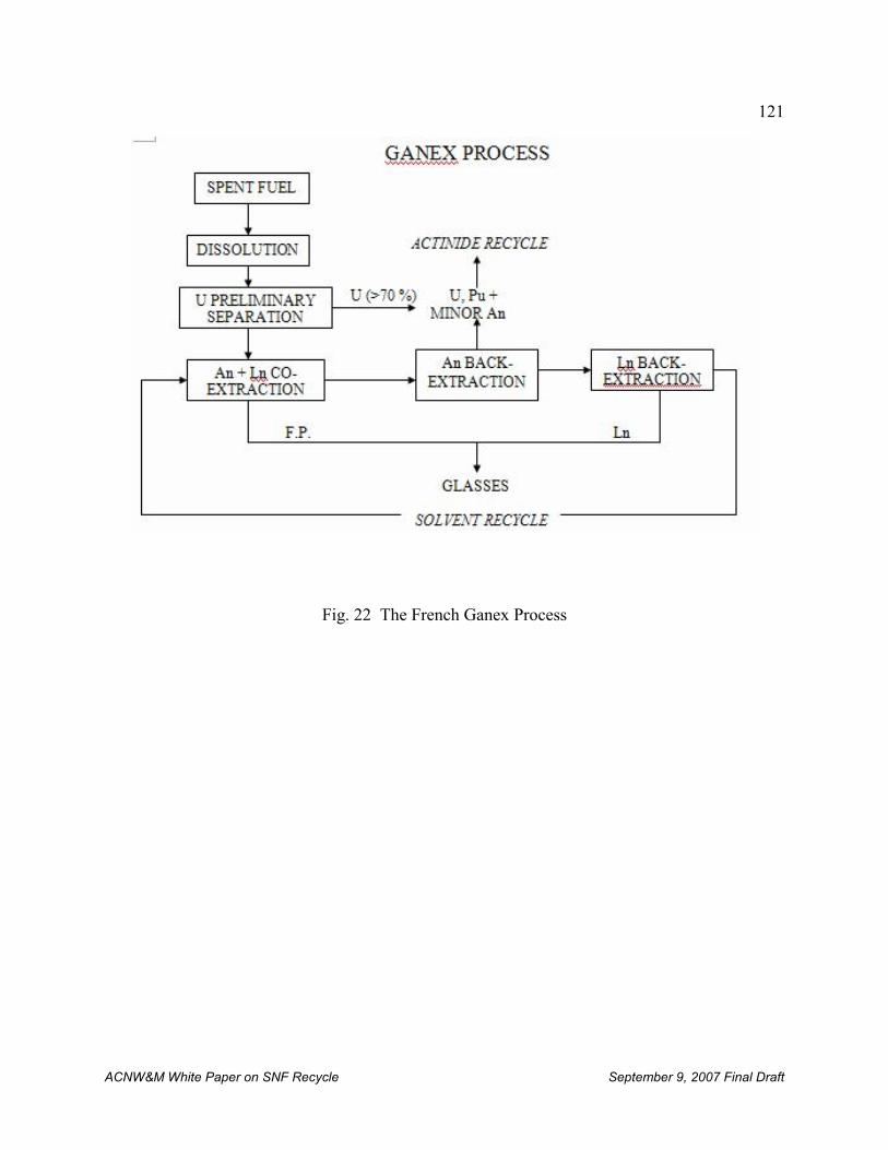
121
ACNW&M White Paper on SNF Recycle September 9, 2007 Final Draft
Fig. 22 The French Ganex Process
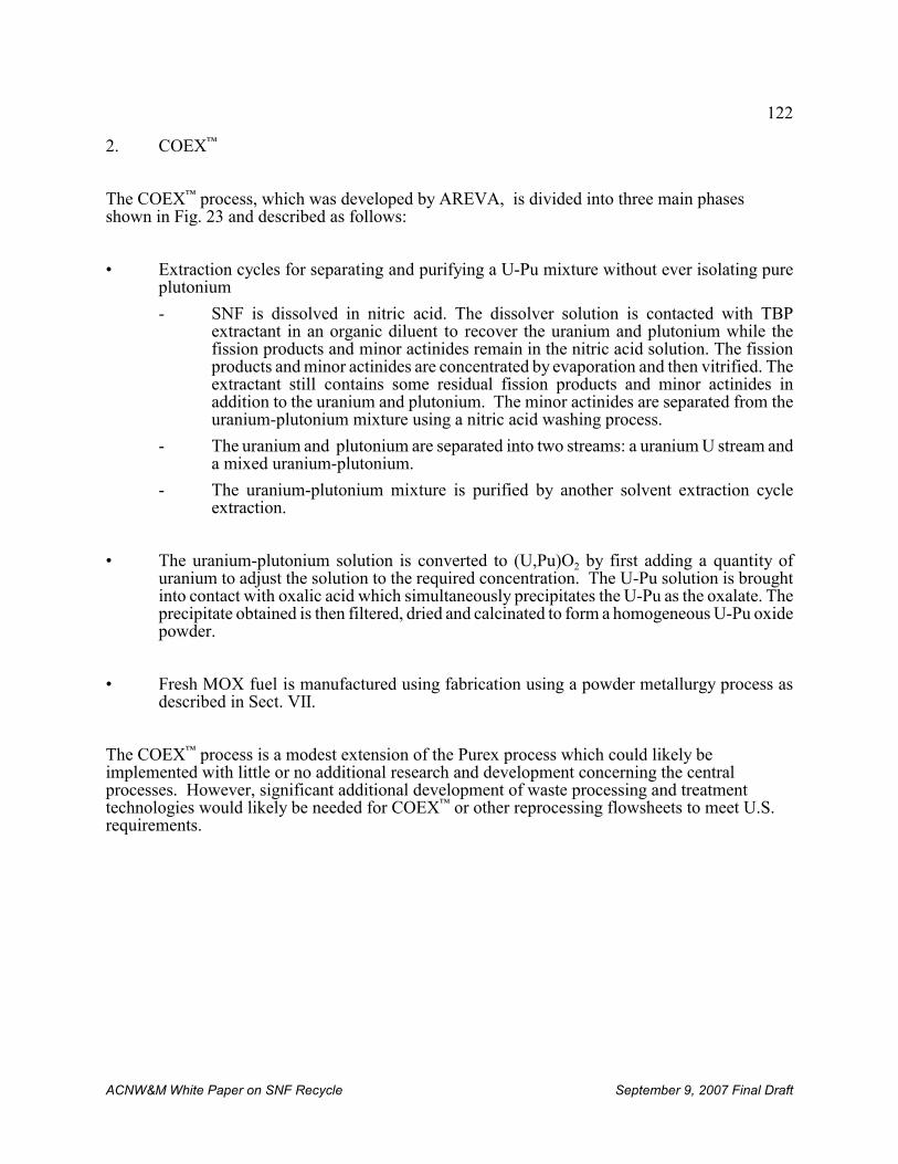
122
ACNW&M White Paper on SNF Recycle September 9, 2007 Final Draft
2. COEX™
The COEX™ process, which was developed by AREVA, is divided into three main phasesshown in Fig. 23 and described as follows:
• Extraction cycles for separating and purifying a U-Pu mixture without ever isolating pureplutonium
- SNF is dissolved in nitric acid. The dissolver solution is contacted with TBPextractant in an organic diluent to recover the uranium and plutonium while thefission products and minor actinides remain in the nitric acid solution. The fissionproducts and minor actinides are concentrated by evaporation and then vitrified. Theextractant still contains some residual fission products and minor actinides inaddition to the uranium and plutonium. The minor actinides are separated from theuranium-plutonium mixture using a nitric acid washing process.
- The uranium and plutonium are separated into two streams: a uranium U stream anda mixed uranium-plutonium.
- The uranium-plutonium mixture is purified by another solvent extraction cycleextraction.
• The uranium-plutonium solution is converted to (U,Pu)O2 by first adding a quantity ofuranium to adjust the solution to the required concentration. The U-Pu solution is broughtinto contact with oxalic acid which simultaneously precipitates the U-Pu as the oxalate. Theprecipitate obtained is then filtered, dried and calcinated to form a homogeneous U-Pu oxidepowder.
• Fresh MOX fuel is manufactured using fabrication using a powder metallurgy process asdescribed in Sect. VII.
The COEX™ process is a modest extension of the Purex process which could likely beimplemented with little or no additional research and development concerning the centralprocesses. However, significant additional development of waste processing and treatmenttechnologies would likely be needed for COEX™ or other reprocessing flowsheets to meet U.S.requirements.
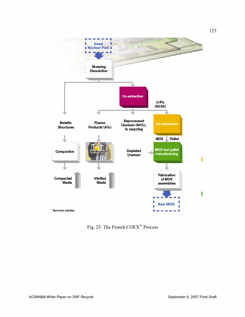
123
ACNW&M White Paper on SNF Recycle September 9, 2007 Final Draft
Fig. 23 The French COEX™ Process
124
ACNW&M White Paper on SNF Recycle September 9, 2007 Final Draft
E. General Electric’s Pyroprocess
General Electric (GE) [Loewen, 2007] has proposed a path to deploy the GNEP CFTC based onANL’s pyrometallurgical process that GE claims has had extensive testing not only in the U.S.,but also in Russia, Japan and South Korea. The proposed process is based on a modular conceptthat would be sized to support an fast transmutation reactor for actinide burning. It is claimed tobe proliferation resistant and to have a low environmental impact. The process would beoperated either batchwise or continuously.
Although the pyrometallurgical process is best suited to spent metallic fuels, as noted above, itcould be adapted to oxide fuels through use of cathodic or carbon reduction of the oxide in amolten LiCl at 650° C to produce metal. The oxygen or CO2 would be released. This reductionhas been demonstrated at ANL at a kilogram scale.
It is planned to demonstration the electro-reduction at GE’s Wilmington, SC plant using thecurrent SNM license and then to license a site using lessons learned at the Wilmington plant.
125
ACNW&M White Paper on SNF Recycle September 9, 2007 Final Draft
VII. ADVANCED FUEL REFABRICATION
Current preparation of conventional pelletized reactor fuels for LWRs and fast reactors (see Sect.III.B) requires grinding to achieve specified size and shape. This process produces finelydivided fuel particles that must be recovered and recycled. A “dust-free” sol-gel microspherepelletization process has been developed for fabrication of (U,Pu)O2, (U,Pu)C and (U,Pu)N fuelpellets containing around 15% plutonium [Ganguly, 1997]. The microspheres can be pressed intopellets that can be sintered to 85% of theoretical density in Ar+8% H2 at 1700EC. The sinteredoxide, monocarbide and mononitride pellets have an open pore microstructure with fine grainsize.
Hydrated gel-microspheres of UO3/PuO2 and UO3/PuO2/C are prepared from nitrate solutions ofuranium and plutonium by the “ammonia internal gelation” process, using hexamethylenetetramine that decomposes to ammonia in the presence of silicone oil at 90±1EC in a gelationbath. For oxide fuel pellets, the hydrated UO3/PuO2 gel-microspheres are calcined at around700EC in Ar/8% H2 atmosphere to produce “non-porous”, “free-flowing” and coarse (around 400micron) microspheres which are directly pelletized at 550 MPa to green pellets. The mixed oxidepellets are subjected either to low temperature (~1100EC) oxidative sintering in N2/air containing~1500 ppm O2 or to high temperature (~1650EC) sintering in Ar/8% H2.
For monocarbide and mononitride pellets, hydrated gel-microspheres of UO3/PuO2/C weresubjected to carbothermic synthesis in vacuum (~1 Pa) and flowing nitrogen (flow rate: 1.2 m3/h)in the temperature range of 1450–1550EC. The microspheres retain their individual identity inthe sintered pellets because during sintering densification takes place mainly within and notbetween the microspheres.
Metallic fuels of U/Pu/Zr continue to be of considerable international interest because of theirvery promising performance at high fuel burnup in fast reactors.
126
ACNW&M White Paper on SNF Recycle September 9, 2007 Final Draft
VIII. REGULATION AND LICENSING OF FUEL RECYCLE FACILITIES
A. Licensing – An historical perspective
Application of NRC’s regulatory process to commercial recycle facilities will not be simple. Deficiencies in regulations are known to exist that will require new rule making or manyexemptions before a license can be approved, for example for reprocessing spent nuclear fuel ata commercial site. The body of regulations that currently establishes NRC’s licensing andregulatory process for recycle facilities, associated waste streams, and effluents include at leastthe following requirements in Title 10 of the Code of Federal Regulations:
Licensing Process – Part 50/52 and Part 70
Radiation Protection – Part 20
Environmental Protection – Part 51
Reprocessing – Part 50
Fuel Fabrication – Part 70
HLW Vitrification and Storage – Part 70
Uranium product conversion – Part 40
Plutonium product conversion – Part 70
Reprocessed Uranium Storage – Part 70
Low-Level Waste Disposal – Part 61
Disposal of HLW at Yucca Mountain – Part 63
Spent Nuclear Fuel Storage – Part 72
Cs/Sr and TRU Storage – Part 30 and Part 70
Transportation – Part 71
Physical Protection – Part 73
Material Control and Accountability – Part 74
Decommissioning – Part 50 and Part 51
This chapter focuses on SNF reprocessing because there has been significant experience withlicensing fuel fabrication plants. However, only limited regulatory experience exists concerninglicensing and regulating reprocessing facilities. Most of this experience occurred decades agounder the AEC and the then newly formed NRC.
1. Licensing experience at Nuclear Fuel Services
In 1966 the U.S. Atomic Energy Commission (AEC) used Part 50 to license Nuclear FuelServices (NFS) reprocessing facility at West Valley. From 1966 to 1972 NFS reprocessed 640
127
ACNW&M White Paper on SNF Recycle September 9, 2007 Final Draft
metric tons of fuel, but in1972 the facility shut down to implement a number of improvementsand never restarted. Since that time no other licenses were approved by the NRC forreprocessing spent nuclear fuel, although the BNFP had been undergoing a licensing reviewwhen President Carter terminated commercial reprocessing. Although some 30 years havepassed since then, 10 CFR Part 50 still remains the default licensing basis for reprocessing spentnuclear fuel. Many changes have occurred to Part 50 over that time frame, but most relate tolicensing utilization or power reactor facilities as opposed to reprocessing facilities like NFS.
2. Licensing experience at Barnwell
The Preliminary Safety Analysis Report for the BNFP Separations Facility was submitted onNovember 6, 1968. Following appearances before the Advisory Committee on ReactorSafeguards and a public hearing before an Atomic Safety and Licensing Board, a ConstructionPermit was issued on December 18, 1970. Subsequently, several substantial documents weresubmitted to the AEC, including: Environmental Report and Facility Safety Evaluation for theUranium Hexaflouride Facility; Updated Environmental Report for the Separations Facility;Final Safety Analysis Report for the Separations Facility (five volumes and several addenda);Technical Description in Support of Application for FRSS Operation; Preliminary SafetyAnalysis Report for Plutonium Product Facility; and Nuclear Materials Safeguards Supplement. In addition, the applicant submitted a large number of documents containing responses toquestions by the AEC.
A public hearing was conducted before an Atomic Safety and Licensing Board to comply withthe National Environmental Policy Act and preliminary to the issuance of an Operating License. The compliance with applicable regulations and the commitment implicit in issuing theConstruction Permit were verified by the AEC who conducted more than 20 formal inspectionsprior to the cessation of commercial licensing activities (brought about by Presidents Carter andFord.).
Some facilities and operations of the plant complied with 10 CFR Part 50 regulations, whileother facilities such as the plutonium nitrate conversion plant complied with 10 CFR Part 70. Inthe past, the licensing process was complicated by the evolutionary character of regulationspertaining to reprocessing plants and waste management, and the inter-relation between thelicensing of the facility and other regulatory actions taking place concurrently. Notable amongthose were the proceedings on the Generic Environmental Statement on Mixed Oxide Fuel(GESMO) and the Environmental Statement on the Management of Commercial High-Level andTransuranic Contaminated Radioactive Waste. These latter activities, however, were placed onhold when the International Nuclear Fuel Cycle Evaluation (INFCE) was invoked.
B. Current licensing process and alternatives
Under current regulations, both production (reprocessing) and utilization facilities (powerreactors) must comply with 10 CFR Part 50 to obtain a construction or operating license. Toensure adequate protection of public health and safety, Part 50 requires that applicantsdemonstrate their designs meet general design criteria, and mitigate a postulated set of accidentsknown as “design basis” accidents (DBAs) to within certain specified radiological release limits.
128
ACNW&M White Paper on SNF Recycle September 9, 2007 Final Draft
Plant-specific probabilistic risk assessment (PRA) insights are used by applicants (but notrequired under Part 50) to ensure that the plant is protected against a robust set of accidents.
Part 50 was not written specifically for reprocessing spent nuclear fuel, and has somedeficiencies for that use. For example, in Classification and Description of Licenses, §50.20,there is no specific acknowledgment of licensing reprocessing plants, and §50.34 (a) Contents ofapplications; technical information is directed solely to reactors. The NEPA process, andrequired documentation for a reprocessing facility has yet to be completely demonstrated. Earlier efforts in this regard for commercial reprocessing plants were subsequent to thesubmission of the safety analysis report and thus were very time consuming and contentious. Aswritten today, modification of Part 50, or exemption to its requirements would be needed toaccommodate the technical differences between licensing light-water reactors and reprocessingfacilities. Rule modifications could be extensive and public hearings on exemptions are likely todrag the process out.
All fuel fabrication facilities are licensed under 10 CFR Part 70 Subpart H AdditionalRequirements for Certain Licensees Authorized to Possess a Critical Mass of Special NuclearMaterials. Experience and lessons learned from licensing fuel fabrication facilities under Part 70is to some extent applicable to reprocessing facilities. Part 70 utilizes an integrated safetyanalysis (ISA), sometimes known as a process hazards analysis, to assess the safety of the designand to identify equipment relied on for safety. Use of ISA is an important step towards riskquantification and expanded use of risk-informed regulations, however, in a January 14, 2002letter to the Commission, the Joint Subcommittee of the Advisory Committee on ReactorSafeguards and the Advisory Committee on Nuclear Waste noted shortcomings in ISAs thatwould likely need to be addressed to expand its role in regulatory decisions involvingreprocessing facilities. Additionally, measurable limits would need to be established andimplemented on emissions from refabrication facilities to ensure public and environmentalprotection.
At the time of this writing, a new rule (10 CFR Part 53, Risk-Informed, Performance-BasedFramework) is under development. Part 53 is expected to provide a risk-informed, performancebased framework for licensing the next generation of nuclear reactor designs. The frameworkintegrates safety, security, and emergency preparedness to establish a comprehensive set ofrequirements as a license condition. The approach focuses on the most risk-significant aspectsof plant operations, and uses the Commission’s safety goals (separate goals would need to bedeveloped for recycle facilities) as top level regulatory criteria that designers must meet toensure adequate safety. The approach eliminates the need for exemptions by implementingguidance to accommodate technological differences between designs. Such an approach tolicensing reprocess facilities may be advantageous because of its flexibility. Part 53, however, isprimarily intended for new commercial power reactors and its current schedule may not supportits application to reprocessing facilities.
In addition to the modification of existing regulations, a new rule could be designed specificallyfor licensing recycle facilities. The rule would avoid the need to write exemptions for rulesalready in place, and place all the regulations relevant to the recycle facilities under one part ofthe regulations, effectively leaving other parts of the regulations unchanged. The rule could bemade to expedite the licensing processing by eliminating exemptions and long drawn-outhearings. The drawback is that extensive resources and time are likely to be required to develop
129
ACNW&M White Paper on SNF Recycle September 9, 2007 Final Draft
such a rule although it is unclear whether the requirements are significantly greater than otherapproaches.
It is expected that implementation of any new or modified rule would be consistent withCommission policies including the Commission’s Probabilistic Risk Assessment (PRA) PolicyStatement [NRC, 1995]. This Policy Statement states in part: “The use of PRA technologyshould be increased in all regulatory matters to the extent supported by the state of the art inPRA methods and data, and in a matter that complements the NRC’s deterministic approach andsupports the NRC’s traditional defense-in-depth philosophy.” The Committee has gone onrecord repeatedly in letters to the NRC Commission about the use of risk-informed decisionmaking, starting in October of 1997 and most recently in a May 2, 2006 letter. These letters arelisted in Appendix C. Additionally, ALARA requirements for reprocessing facilities thatestablish design objectives and limiting conditions for radioactive material effluents, analogousto the current Appendix I for LWRs will need to be formulated.
C. Environmental Protection
Production and utilization facilities need to comply with environmental protection regulations. Protection is provided by both (1) designed-in barriers that block the release of radioactivematerial to the environment, and (2) operational performance and characteristics that limit therelease of radioactive material to the environment.
1. Design Perspective
Prior to facility construction,10 CFR Part 51, Environmental Protection Regulations forDomestic Licensing and Related Regulatory Functions, requires that each applicant submit anenvironmental report that complies with Table S-3 §51.51(b), Table of Uranium Fuel CycleEnvironmental Data, as the basis for evaluating the contribution of its activity to theenvironment. Currently, Table S-3 only considers two fuel cycles, uranium-only recycle and norecycle. To accommodate recycle of plutonium and other actinides, the applicability of Table S-3 and S-4, “Environmental Impact of Transportation of Fuel and Waste to and From One Light-Water-Cooled Nuclear Power Reactor,” at §51.52(c) would need to be considered to determine ifit encompasses the releases of radioactive waste to the environment. This would includeinformation on the impact of fuel recycle affecting other environmental considerations listed inTable S-3 beyond the release of radioactivity, e.g., land (temporarily committed), occupationalexposure, water discharges. Table S-4 would also need to be reconsidered to determine if itencompasses the environmental impact of transportation of fuel and radioactive waste, takinginto consideration the changes introduced by the recycling of spent nuclear fuel.
An applicant for a fuel recycling facility would need to provide an environmental report with theinformation required by 10 CFR 51.45. The applicant would need to develop and provideinformation on the other stages of the fuel cycle analogous to the information in Tables S-3 andS-4, which are applicable to LWRs. Establishing a new set of tables analogous to S-3 or S-4explicitly for reprocessing facilities may be the best approach should reprocessing become amainstream activity. 10 CFR 51.45(d) requires that an “Environmental Report” be prepared thatincludes a discussion of the status of compliance with the applicable environmental quality
130
ACNW&M White Paper on SNF Recycle September 9, 2007 Final Draft
standards and other requirements including those imposed by Federal, State, regional and localgovernment agencies.
The EPA Standard (40 CFR Part 190, Environmental Radiation Protection Standards forNuclear Power Operations) places limits on the entire fuel cycle and applicants seeking todesign their facility would need to comply. Additionally, this standard does not encompassplutonium or actinide refabrication and reuse in a reactor and it would appear necessary do so.
Following the receipt of the environmental report, it will be necessary to prepare anenvironmental impact statement (EIS) for siting, construction and operation of the recycleplant(s). This requirement can be very time consuming and contentious and must be started wellin advance of planned plant construction. The design of a spent fuel reprocessing plant, forexample, is dictated to a large extent by the requirements to (a) protect the plant operators fromradiation, to provide a safe working environment, and to prevent criticality and (b) limit routineand accidental releases of radionuclides to the public.
The design must be such that the protection provided by the radiation shielding and confinementof radioactivity keep radiation doses ALARA and are consistent with the allowable limits ofpersonnel dose (Part 20), and air and water contamination (Appendix I to part 50). Exceptions tothe dose limits may be made in the case of Planned Special Exposures, but in any case theALARA principle applies.
2. Operating Perspective
In 1974, the AEC initiated a study to examine the environmental impact from spent nuclear fuelreprocessing and widespread use of mixed-oxide fuel (MOX) fuel as a means to use the uraniumand plutonium products of reprocessing. The study, often referred to as GESMO, was publishedin August 1976 [NRC, 1976]. Five alternatives were considered:
• Prompt fuel reprocessing, prompt uranium recycle, delayed plutonium recycle
• Delayed fuel reprocessing, followed by uranium and plutonium recycle
• Prompt uranium and plutonium recycle
• Uranium recycle; no plutonium recycle
• No uranium or plutonium recycle
Findings from the study found no clear preference for any of the alternatives. Differences inhealth effects between the fuel cycles did not provide a basis for choosing one approach over theanother. Any environmental benefit that did result arose from the conservation of uraniumresources and not from differences in the way radiological waste was managed.
The study found, however, that for the various recycle alternatives (as opposed to the once-through fuel cycle) the collective dose increased by several orders of magnitude. Three radio
131
ACNW&M White Paper on SNF Recycle September 9, 2007 Final Draft
nuclides that were assumed to not be removed from the reprocessing plant gaseous effluentcontributed to this dose: 3H, 14C, and 85Kr. The contribution of 129I and 131I was much smallerbecause most of the iodine was assumed to be removed from the gaseous effluent
.
Although the dose to any one individual was found to be small, the large integrated (world)population exposed to the gaseous effluents drove the results. While public hearings were beingheld on the GESMO study and BNFP license, the Carter Administration terminated reprocessingin the U.S. The public hearings were never completed, and the Commission postponed theirdecision on whether to allow the widescale use of mixed oxide fuel in light water reactors. This could become an issue once again should wide-scale reprocessing be considered as amainstream activity.
About the same time period as the GESMO study (Jan 13, 1977), EPA released 40 CFR 190Environmental Radiation Protection Standards For Nuclear Power Operations, Subpart B . This rule established the environmental standard for the complete uranium fuel cycle. Twocriteria were prescribed:
Subpart B section 190.10 (a) - Annual dose equivalent to any member of the public for theentire fuel cycle,
Whole body < 25 mrem
Thyroid < 75 mrem
Any other organ < 25 mrem
Subpart B section 190.10 (b) - Radioactive material released to the environment per gigawatt-year electrical energy produced,
85Kr < 50,000 curies129I < 5 millicuries
Pu and other alpha emitting
emitting radionuclides with
half-lives > 1 year <0.5 millicuries
The EPA made December 1, 1979 the effective date of Section 190.10(a) except for operationsassociated with uranium milling which were given an effective date of December 1, 1980. Theeffective date for Section 190.10(b) was also established as December 1, 1979 except for 85Krand 129I standards which were effective on January 1, 1983. Soon after the standards werereleased, stakeholders expressed concerns that the standards were overly conservative, costly,and that they would require technology that was considered to be beyond the state-of-the-art. Inaddition, industry believed that requirements should not be established until internationalagreements were reached that would restrict emissions from foreign sources. Nevertheless, EPA approved part of the standard (except for 85Kr) on December 1, 1979, and a 85Kr standardthat was effective on January 1, 1983. By that time all reprocessing activities had ceased andinterest in the new standard vanished.
132
ACNW&M White Paper on SNF Recycle September 9, 2007 Final Draft
Today, the EPA standard for utilization (power reactors) facilities is being met through NRC’senforcement of 10 CFR Part 50, Appendix I, Numerical Guides for Design Objectives andLimiting Conditions for Operation to Meet the Criterion "As Low as Reasonably Achievable"for Radioactive Material in Light-Water-Cooled Nuclear Power Reactor Effluents. 10 CFR Part50 Appendix I sets the following operating limits:
Liquid Effluents < 3 mrem whole body, or
< 10 mrem to any organ
Gaseous Effluents < 5 mrem whole body, or
< 15 mrem to the skin
Radioactive iodine < 15 mrem to any organ
and other material in
particulate form in
effluents to the atmosphere
These limits provide the basis for realistic implementation of EPA standards for single reactorunits. The remaining (non-utilization) portion of 40 CFR 190 release is divided among the restof the fuel cycle which up to now has not included reprocessing.
D. Decommissioning
Decommissioning commercial reprocessing plants can be very costly. There is not muchinformation available based on decommissioning experience because so few reprocessing plantshave been decommissioned.
In 1976 NFS withdrew from the reprocessing business and turned control over to the site owner,the New York State Energy Research and Development Authority (NYSERDA). In 1980, theNRC suspended West Valley’s license to reprocess spent nuclear fuel, and the West ValleyDemonstration Project (WVDP) Act was executed to clean up the site and its facilities. Underthe Act, NRC maintained certain responsibilities including prescribing decontamination anddecommissioning criteria.
Significant lessons learned and regulatory actions have resulted from West Valleydecommissioning experience. The cost to clean up the site to date has exceeded $2 billion,although a fund of only $4 million had been set aside for decommissioning and decontamination.
The English Sellafield reprocessing plant is currently undergoing decommissioning of their “firstgeneration” reprocessing plants, including analytical laboratories, legacy wastes, and the “NorthCompound,” a facility established to support Windscale pile operation and subsequently
133
ACNW&M White Paper on SNF Recycle September 9, 2007 Final Draft
extended to include waste storage. The total estimated cost of this “interim” decommissioning isabout £20 million (equivalent to about $40M) [Sellafield, 2005].
The French UP1 reprocessing plant at Marcoule has an estimated decommissioning cost of €5.6billion (about $7.6B), about half of which is for treating wastes stored on site [Hore-Lacey,2007]. Thus, there is very wide range of real and anticipated reprocessing plantdecommissioning costs. Additional knowledge of decommissioning experience and the extent towhich decommissioning “lessons learned” are incorporated into future plants will be needed tobetter estimate the costs for future reprocessing plant decommissioning.
Shortfalls in decommissioning funding like that at West Valley resulted in 10 CFR Part 50 App.F Policy Relating to the Siting of Fuel Reprocessing Plants and Related Waste ManagementFacilities. Some sections of 10 CFR Part 50, appendix F, relevant to reprocessing plants are:
• Paragraph 3, which states “Disposal of high-level radioactive fission product wastematerial will not be permitted on any land other than that owned and controlled by theFederal Government.”
• Paragraph 2, which states “...High level liquid radioactive wastes shall be converted to adry solid as required to comply with this inventory limitation, and placed in a sealedcontainer prior to transfer to a Federal repository in a shipping cask meeting therequirements of 10 CFR 71...Upon receipt, the Federal Repository will assumepermanent custody of the waste materials although industry will pay the FederalGovernment a charge which together with interest on unexpended balances will bedesigned to defray all costs of disposal and perpetual surveillance.”
• Paragraph 5, which states, “Applicants proposing to operate fuel reprocessing plants, insubmitting information concerning financial qualifications as required by Section50.33(f), shall include information enabling the Commission to determine whether theapplicant is financially qualified, among other things, to provide for the removal anddisposal of radioactive wastes, during operation and upon decommissioning of thefacility.”
Although Part 50, Appendix F might reduce the likelihood of shortfalls in decommissioningfunding, the Commission in an SRM dated February 7, 2006 [NRC, 2006c], directed that animportant design criterion for any new reprocessing effort will be that decommissioning costs bemanageable. NRC guidance under development should help designers address these concerns atthe conceptual design stage.
Any new license application will also need to address how the design and procedures foroperating the facility will minimize contamination of the facility and the environment, andfacilitate eventual decommissioning (Part 20.1406). This includes realistic estimates of thefunds required for decommissioning (Part 72.30), including site characterization, cleanup, wastedisposal, and surveillance. NRC/RES is developing a regulatory guide to implement 10 CFRPart 20.1406 to facilitate decommissioning.
134
ACNW&M White Paper on SNF Recycle September 9, 2007 Final Draft
Additional Nuclear Regulatory Commission regulatory requirements related to decommissioninginclude:
• 10 CFR Part 20
- Subpart E, Regulatory Criteria for License Termination, which gives Radiologicalcriteria for unrestricted use (§20.1402)
- Criteria for license termination under restricted conditions (§20.1403)
- Alternate criteria for license termination (§20.1404)
- Public notification and public participation (§20.1405)
- Minimization of contamination (§20.1406)
• 10CFR Part 72
- Subpart B, §72.30, Financial assurance and record keeping for decommissioning
- Subpart D, §72.54, Expiration and termination of licenses and decommissioningof sites and separate buildings or outdoor areas.
135
ACNW&M White Paper on SNF Recycle September 9, 2007 Final Draft
IX. ISSUES ASSOCIATED WITH LICENSING AND REGULATING FUEL RECYCLEFACILITIES
The focus of this chapter is on licensing and regulation of industrial-scale fuel reprocessing andrefabrication facilities. In consideration of the foregoing information there are a number oflicensing or regulatory issues that warrant consideration before receipt of a license application.The following sections identify these issues and provides insight into their resolution.
A. Selection or development of licensing regulation(s) for recycle facilities
A key issue to be decided before receipt of a license application for SNF recycle facilities iswhat primary regulation(s) should be used to license each facility and the approaches (e.g.,probabilistic vs deterministic safety assessments) to be used in developing a new regulation ormodifying and existing regulation. For the purposes of this paper it is assumed that the specificregulations and approaches used to license well-established fuel cycle facilities and operations(e.g., interim storage of spent fuel, radioactive material transportation, uranium fuel fabrication,reactors) will not change.
The list of novel facilities for which decisions concerning the appropriate licensing regulationsand approaches will be required include:
• Reprocessing fuels from LWRs and later for other advanced reactors
• Fabrication of fuels to recycle transuranic or fission product elements, or for some newreactor designs (e.g., graphite-moderated reactors)
• Disposal of new types of wastes such as cladding and transuranic (GTCC) waste,
• Extended interim storage of intermediate-lived radionuclides, Cs and Sr, followed by insitu disposal.
The following sections discuss some of the factors that should be considered when making thesedecisions.
1. Multiple regulatory paths are available
As was discussed in Sect. VIII, there are a number of existing regulations as well as thepossibility of developing one or more entirely new regulations for licensing recycle facilities. None of the existing regulations is entirely suitable for the fuel recycle facilities. While detailedreasons for this view are given in Sect. VIII.B, the overarching reason is that existing regulationswere designed for (a) reactors where maintaining heat removal capability in situations involvingfast transients in a core with a high power density is an important purpose of the regulations butwhere there are modest chemical hazards and few concentrated solutions of radionuclides, or (b)for facilities that handle relatively small amounts of radioactivity because they only processuranium. Maintaining the fast-response capability to remove large amounts of decay heat is notparticularly important in fuel recycle facilities, but there are substantial amounts of radioactivity
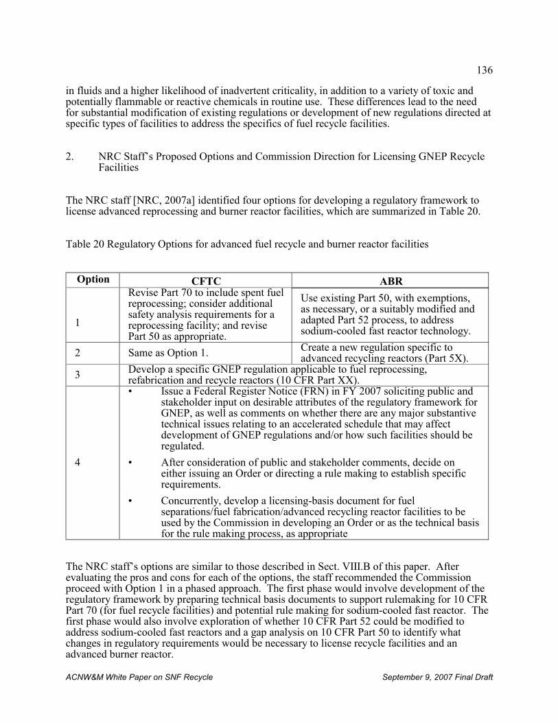
136
ACNW&M White Paper on SNF Recycle September 9, 2007 Final Draft
in fluids and a higher likelihood of inadvertent criticality, in addition to a variety of toxic andpotentially flammable or reactive chemicals in routine use. These differences lead to the needfor substantial modification of existing regulations or development of new regulations directed atspecific types of facilities to address the specifics of fuel recycle facilities.
2. NRC Staff’s Proposed Options and Commission Direction for Licensing GNEP RecycleFacilities
The NRC staff [NRC, 2007a] identified four options for developing a regulatory framework tolicense advanced reprocessing and burner reactor facilities, which are summarized in Table 20.
Table 20 Regulatory Options for advanced fuel recycle and burner reactor facilities
Option CFTC ABR
1
Revise Part 70 to include spent fuelreprocessing; consider additionalsafety analysis requirements for areprocessing facility; and revisePart 50 as appropriate.
Use existing Part 50, with exemptions,as necessary, or a suitably modified andadapted Part 52 process, to addresssodium-cooled fast reactor technology.
2 Same as Option 1. Create a new regulation specific toadvanced recycling reactors (Part 5X).
3 Develop a specific GNEP regulation applicable to fuel reprocessing,refabrication and recycle reactors (10 CFR Part XX).
4
• Issue a Federal Register Notice (FRN) in FY 2007 soliciting public andstakeholder input on desirable attributes of the regulatory framework forGNEP, as well as comments on whether there are any major substantivetechnical issues relating to an accelerated schedule that may affectdevelopment of GNEP regulations and/or how such facilities should beregulated.
• After consideration of public and stakeholder comments, decide oneither issuing an Order or directing a rule making to establish specificrequirements.
• Concurrently, develop a licensing-basis document for fuelseparations/fuel fabrication/advanced recycling reactor facilities to beused by the Commission in developing an Order or as the technical basisfor the rule making process, as appropriate
The NRC staff’s options are similar to those described in Sect. VIII.B of this paper. Afterevaluating the pros and cons for each of the options, the staff recommended the Commissionproceed with Option 1 in a phased approach. The first phase would involve development of theregulatory framework by preparing technical basis documents to support rulemaking for 10 CFRPart 70 (for fuel recycle facilities) and potential rule making for sodium-cooled fast reactor. Thefirst phase would also involve exploration of whether 10 CFR Part 52 could be modified toaddress sodium-cooled fast reactors and a gap analysis on 10 CFR Part 50 to identify whatchanges in regulatory requirements would be necessary to license recycle facilities and anadvanced burner reactor.
137
ACNW&M White Paper on SNF Recycle September 9, 2007 Final Draft
In the second phase the NRC staff would shift to Option 3 and develop a new regulation forGNEP fuel recycle and reactor facilities. The analyses performed in the first phase would beused to evaluate whether there are unique programmatic or technical interrelationships among allclosed fuel cycle technologies as a basis for developing a new regulation for advanced fuelrecycle and burner reactor facilities.
In a SRM responding to the NRC staff’s recommendations, the Commission [NRC, 2007b] directed the NRC staff to begin developing the regulatory framework to license SNF recyclefacilities using an option based on 10 CFR Part 70 by preparing:
• A technical basis documentation to support rulemaking for 10 CFR Part 70 with revisionsto 10 CFR Part 50 as appropriate to eliminate its applicability to licensing a SNFreprocessing plant, and
• A gap analysis for all NRC regulations (10 CFR Chapter I) to identify changes inregulatory requirements that would be necessary to license a reprocessing facility.
Title 10 CFR Part 70 has been used to license fuel fabrication facilities and is currently the basisfor reviewing the license application for the Mixed-Oxide Fuel Fabrication Plant (MFFP) on theSavannah River Site. Experience and lessons learned from previous and ongoing use of 10 CFRPart 70 to license fuel fabrication facilities are likely to be useful when deciding how it should bemodified to license SNF recycle facilities.
3. Important factors in developing regulations for SNF recycle facilities
There are important aspects of 10 CFR Part 70 and potential modifications thereto that will needto be considered for it to be an efficient and effective regulation for licensing SNF recyclefacilities, such as:
• Use of an Integrated Safety Analysis (ISA): 10 CFR Part 70 calls for the use of an ISA toevaluate the in-plant hazards and their interrelationship in a facility processing nuclearmaterials. Doses to the public are typically estimated using a scenario-based approach. Use of ISA is an important step towards quantifying risk as compared to traditionalconservative, scenario-based deterministic approach. The primary reason for this is theconsequences of accidents in or routine releases from fuel cycle facilities is relativelysmall compared to consequences of accidents at reactors and the effort of doingprobabilistic analyses has not been justified. However, the effort required to prepare anISA that is adequate for complex SNF recycle handling liquids containing substantialquantities of concentrated cesium, strontium, and transuranic elements is likely toapproach the effort that would be required to evaluate risks using a probabilistic riskanalysis (PRA). The Committee and the ACRS have previously recommended[ACNW&M, 2002, 2006] that a regulation based on PRA is preferable to one based onISA because the latter has significant limitations regarding its treatment of dependentfailures, human reliability, treatment of uncertainties, and aggregation of eventsequences.
138
32 NRC Commission defined risk-informed regulation in their white paper, "Risk-Informed and Performance-BasedRegulation" as “...a philosophy whereby risk insights are considered together with other factors to establishrequirements that better focus licensee and regulatory attention on design and operational issues commensurate withtheir importance to public health and safety.”
ACNW&M White Paper on SNF Recycle September 9, 2007 Final Draft
• Best estimate vs conservative: A companion issue to that of probabilistic vs.deterministic approaches is whether analyses should be based on data and models thatrepresent the best estimate of what might really occur with an associated uncertaintyanalysis to explore the effects of incorrect data or models, or should be based ondemonstrably conservative data and models. Most regulations and license applicationsfor fuel cycle facilities have used a conservative, deterministic approach. The Committeehas letters on record pointing out problems with using this approach (see Appendix C)with some of the most important being that using very conservative assumptions canmask risk-significant items, and that most conservative analyses are not accompanied bya robust uncertainty analysis.
In at least one recent instance DOE has used a dose assessment based on best estimates[DOE, 2005]. This, when accompanied by a robust sensitivity and uncertainty analysismight be appropriate for less complex fuel cycle facilities. While a probabilistic analysisbased on conservative data and models could be performed, there is no evident benefit todoing so and the conservatism would render the accompanying uncertainty analysismeaningless.
• One-Step Construction and Operating License (COL): 10 CFR Part 70 allows for a one-step licensing process which means that the design and process details necessary toreview the adequacy of a recycle facility would not available until relatively late in thelicensing process. This approach is likely to be more efficient for the NRC and lessburdensome to the applicant than the traditional two-step licensing process for facilitiescontaining well established processes and equipment and where there is a base oflicensing experience (e.g., reactors, fuel fabrication plants). However, SNF recyclefacilities have the potential to involve equipment, chemicals, and processes that areunfamiliar to NRC staff and that could result in the need for multiple requests foradditional information from licensees and/or extensive pre-licensing interactions betweenNRC staff and the licensee to identify and resolve potential licensing issues. Theproposed Yucca Mountain repository is an example of an unfamiliar facility where a two-step licensing process has been adopted and extensive pre-licensing interactions haveoccurred.
• Accommodating the Potential Future Diversity of 10 CFR Part 70 License Applications:10 CFR Part 70 is also used to license many nuclear material processing facilities otherthan those for fuel recycle. Such facilities are typically much smaller, less costly, andless complex than anticipated SNF recycle facilities to the point that imposingrequirements appropriate for recycle facilities could be unduly burdensome to someapplicants.
• Risk-informed, Performance-Based32: A risk-informed regulatory approach is one inwhich risk provides an important insight for licensing a facility but where otherconsiderations such as cost, environmental impacts, etc. can be balanced against therequired extent of risk reduction. The ALARA philosophy epitomizes a risk-informedapproach. Risk-informed regulations and licensing approaches for a wide range of
139
ACNW&M White Paper on SNF Recycle September 9, 2007 Final Draft
situations and the opportunities for focusing scarce resources on the most-risk significantitems in very complex facilities would indicate its appropriateness in this instance. It isprudent for regulations for licensing fuel recycle facilities to include provisions thatallow the regulator to make exceptions on a case-by-case basis.
A corollary factor to a regulation being risk-informed is that it is performance-based. That is, the criteria for granting a license are expressed in terms of the requirements theapplicant must meet but not the means by which the applicant meets the requirement. For example, a regulation that requires that a dose limit be met is performance based butone that requires use of a specific technology is not.
• Programmatic Specificity of Changes to 10 CFR Part 70: The NRC staff paper presentingoptions for licensing SNF recycle facilities focused on DOE’s GNEP and the facilitiescurrently being proposed by DOE. The scope, functional requirements, size, and timingof these facilities is still evolving and likely to change in unknowable ways in response tofactors such as technology development, budget considerations, stakeholder input, andbroader U.S. and international decisions on nuclear and energy policy. It would beinefficient to initially develop program-specific regulations and then have to revisit theregulations in the future for the purpose of generalizing them.
B. Impacts on related regulations
In addition to the need to establish the approach(es) to be used for the primary licensingregulations for fuel recycle facilities, it will be necessary to evaluate the impact that recyclefacilities and operations might have on other regulations that might be invoked in the licensingframework or that might not yet exist and have to be developed. The following sections discussvarious features of fuel recycle facilities and operations and how these features might impactregulations other than the primary regulation.
1. Potential impacts of new radioactive product, effluent, and waste materials
a. Identification of new product, effluent, and waste materials from SNF recycle
Fuel recycle facilities using any of the UREX process would produce a variety of newradioactive product, effluent, and waste materials for which the current NRC regulatory systemmay not be adequate. Examples of new materials are:
• Recovered uranium that will contain small amounts of contaminants such as transuranicactinides (e.g., 237Np), fission products (e.g., 99Tc), 232U, and 236U.
• A gaseous effluent stream from the fuel reprocessing plant that initially contains most ofthe intermediate-to-long-lived volatile radionuclides such as 129I, 85Kr, 14C, and 3H in thefuel fed to the plant. Historically in the U.S. most (~99%) of the 129I has been removed
140
ACNW&M White Paper on SNF Recycle September 9, 2007 Final Draft
from the effluent stream and managed as a solid waste. At present the La Hague plantand THORP capture the iodine by caustic scrubbing and release it to the sea, relying onthe enormous amount of iodine in the sea to provide adequate isotopic dilution. Causticscrubbing also captures 14C which is released to the sea. The new Rokkasho-Murareprocessing plant will capture the iodine on a solid sorbent the disposition of which hasnot yet been decided. Radionuclides in the gaseous effluent other than those mentionedare being released to the atmosphere.
• Spent fuel metal hardware containing small amounts of residual spent fuel, andpotentially the dissolver solids and 99Tc, that has been melted to form a monolith orcompacted.
• Wastes containing a mixture of recovered cesium and strontium including theintermediate-lived radioactive isotopes 135, 137Cs and 90Sr plus very small amounts of theirshort-lived (137mBa and 90Y) isotopes and amounts of their stable (135,137Ba and 90Zr) thatare eventually equivalent to the initial amounts of 135, 137Cs and 90Sr.
• Substantial volumes of materials and equipment contaminated with greater than 100 nCi/g of transuranic radionuclides
• A fission product waste stream containing lanthanides and other fission products that isless radioactive and decays more quickly than what has been produced or planned for inthe past
The estimated volumes, masses, radioactivity, thermal power, and classification of wastes from
the UREX +1a flowsheet are presented in Table 19. Production of these wastes would raise anumber of issues that are discussed in the following paragraphs.
b. Classification of wastes
Classification of the wastes is an important determinant of how they must be treated, stored,transported, and disposed of. Under current law and regulations the classification of the variouswastes would range from Class A LLW to HLW. However, many of these wastes and theproposed management approach associated with them were not anticipated as the current wasteclassification system evolved so the appropriateness of the classification remains open toquestion. Specific questions regarding waste classification include:
• Whether the Cs/Sr waste will require a waste determination and DOE decision that it is“wastes incidental to reprocessing” (WIR) so that it would not require disposal in a deepgeologic repository.
• The stable end point of cesium decay is stable isotopes of barium. A waste containingbarium is considered to be characteristically hazardous by virtue of its toxicity if the
141
ACNW&M White Paper on SNF Recycle September 9, 2007 Final Draft
leach rate of the barium in standardized tests exceeds a prescribed limit. As aconsequence, leaching tests will have to be performed on the Cs/Sr waste form toascertain whether leached barium concentrations are too high and, if so, the waste willrequire further treatment before disposal or be managed as a mixed waste.
• Existing technology can reduce the TRU element and other radionuclide concentrationsin any uranium product deemed to be a waste sufficiently low so that the waste would beClass A LLW. Waste containing 85Kr and 135Cs in any concentration would be Class ALLW under the present system because these radionuclides are not listed in the wasteclassification tables in 10 CFR Part 61. Such wastes were not contemplated when thewaste classification tables in 10 CFR Part 61 were finalized and the appropriateness ofthese classifications requires further evaluation.
c. Waste forms
Determination of the requirements for waste forms and packaging for wastes such as the volatileradionuclides, 137Cs, and 90Sr is necessary to define how the waste must be treated and also has asignificant impact on the selection of recovery processes for some species such as those ingaseous effluents. Waste form options for the volatile radionuclides were studied in the 1970sand 1980s but process development was not completed and a preferred waste form was notselected. Selection of a waste form for 85Kr is particularly challenging because it is a non-reactive gas under all but extreme conditions. Large amounts of 137Cs and 190Sr have been madeinto chloride and fluoride chemical forms, respectively, and stored by DOE in water pools atHanford for decades. However, the chloride and fluoride do not appear to be appropriate formsfor near-surface disposal such as that being suggested by DOE. DOE has proposed using analuminosilicate waste form. 10 CFR Part 61 does not address waste forms or packaging forthese materials even if they were to be classified as Class C or less, and there is no regulationaddressing the form of GTCC LLW.
d. Distribution of radionuclides in product, effluent, waste, and process streams
There is no technical basis for predicting the distribution of some radionuclides in recycle plantproduct, effluent, waste, and process streams. This distribution is necessary for DOE todetermine the process routing required by each stream (e.g., does a stream that contains iodinethat would be released during subsequent high-temperature processing need to go to iodinerecovery?). This distribution is also necessary for NRC to estimate doses from release ofeffluents or disposal of wastes, and to evaluate the consequences of accidents. Importantradionuclides in this regard include:
• Tritium: To what extent is the zirconium tritide on cladding surface released duringvoloxidation, during acid dissolution of the SNF, and during the melting of the fuelassembly hardware to yield DOE’s proposed waste form?
• Iodine: Do iodine species form that are not trapped by available technologies and whichmight exceed the ~0.5% allowable release? What fraction of the iodine is associated
142
ACNW&M White Paper on SNF Recycle September 9, 2007 Final Draft
with dissolver solids and what fraction is released when the dissolver solids are includedin the final waste form that involves high-temperature melting?
• Technetium and neptunium: What fraction of the technetium is associated with thedissolver solids (e.g., as PdI2)? Of the neptunium and dissolved technetium, a small butpotentially significant fraction can be found in various waste streams. What fractions areassociated with the various waste streams and products from the reprocessing plant?
-• Cladding: How much of the SNF remains with the cladding? Is the radionuclidedistribution the same as the SNF or are some elements preferentially associated with thecladding? This is somewhat important in a waste disposal situation but would be veryimportant DOE proposals involving recycling the cladding material becomes reality.
e. Disposal technology
Requirements for disposal technologies appropriate for some of the wastes listed above has notbeen determined. For those wastes classified as GTCC the technology and possibly a specificsite may be identified as part of DOE’s ongoing effort to prepare an EIS on this subject. TheGTCC disposal facility will be licensed by the NRC using a regulatory framework that has notbeen decided. However, it is not evident that the EIS will consider potential GTCC wastes thatare unique to recycle such as cladding waste, 137Cs and 90Sr, miscellaneous wastes containinggreater than 100 nCi/g TRU (e.g., equipment and analytical wastes, protective equipment, HEPAfilters), and wastes containing 99Tc, 129I, and 14C.
Identification of requirements for an appropriate disposal technology (i.e., the acceptability ofnear-surface disposal and conditions for same) for intermediate-lived radionuclides such as 85Krand tritium may depend on the ability of the selected waste form or package to containsubstantial inventories and concentrations of these radionuclides until they decay to innocuouslevels.
Uranium recovered from fuel reprocessing may exceed its demand leading to the potential needto dispose of some of it. Determination of the acceptability of this uranium for near-surfacedisposal will need to consider the potential risks from species such as 237Np and 99Tc that areoften more mobile than uranium under the geohydrological conditions that prevail in the near thesurface at many sites and the affect of the 232, 236U on the radiological impacts of the uranium. The NRC staff is undertaking an analysis of whether depleted uranium warrants inclusion in thewaste classification tables in 10 CFR Part 61 pursuant to Commission direction [NRC, 2005].
f. Repository licensing regulations
Use of the any of the UREX flowsheets for recycle would change the fundamental nature of adeep geologic repository to the point that the requirements in existing repository regulationswould require re-evaluation. By removing essentially all of the actinides (uranium and heavier),137Cs, 90Sr, 99Tc, and 129I, potentially the cladding, tritium, 14C, and 85Kr from the repository the
143
ACNW&M White Paper on SNF Recycle September 9, 2007 Final Draft
result would be a compact repository waste generating considerably less penetrating radiationand decay heat that will decay much more quickly than for SNF or traditional HLW. Theamount of actinides and long-lived radionuclides that dominate risks estimates for the currentlyproposed repository would be reduced to levels that might make other radionuclides that arepresently not risk-significant dominant in performance assessments. If some of the long-livedwastes mentioned above (Tc, I, C, cladding, and solid wastes containing some transuranicelements) were to be disposed of in the deep geologic repository, the waste volume wouldincrease somewhat and it would introduce some radionuclides important to public risk in newwaste forms for which there is little experience in predicting long-term performance. As aconsequence of the foregoing, aspects of existing regulations and guidance concerningrepository licensing that are driven by decay heat, penetrating radiation, the actinides, thedegradation rates of the spent fuel cladding and matrix, and the dominance of radionuclides suchas 99Tc and 237Np may become irrelevant. On the other hand, the performance of multiple (andpresently unknown) waste forms tailored to specific radioelements over very long time periodscould become very important. The implications of this to the requirement to predict theperformance of the repository to the time of peak dose has yet to be determined.
g. Uranium handling and disposal facilities
The additional radionuclides present in recovered uranium as compared to unirradiated uraniumneed to be taken into account when recycling the uranium to enrichment plants or handling it inother parts of the fuel cycle. The non-uranium isotopes tend to accumulate in certain portions ofenrichment equipment and to be concentrated into a waste stream by decontamination operationsduring maintenance. This requires that enrichment plants have features to (a) process wastescontaining transuranic and fission product elements, and (b) detect beta-emitting radionuclidesand distinguish among alpha-emitting radionuclides. The 236U is a neutron absorber that detractsfrom the value of the recycled uranium and leads to increased production of 237Np in fuel madefrom it. While present in very small quantities (about 1 ppbw), decay of the 232U in therecovered uranium to a 208Tl decay product that emits a very penetrating 2.62 MeV gamma raythat must be taken into account when designing facilities for handling recycled uranium.
2. Novel facilities
a. Cs/Sr Storage/Disposal Facility
Fuel recycle using a UREX flowsheet or similar would require facility types that have not beenlicensed in decades or ever. Regulatory issues concerning many of the major facilities werediscussed in Sect. VII and issues concerning licensing a GTCC disposal facility were discussedin Sect. IX.B.1 and will not be repeated here. However, DOE is considering a disposaltechnology that has not been anticipated in existing regulations. Specifically, DOE isconsidering an engineered near-surface interim storage facility that will store 135, 137Cs and 90Srwaste forms for about 300 years at which time the radionuclides will have decayed to less-than-Class C levels. At that time the storage facility will be converted to a disposal facility with thewaste forms remaining in place. Using this type of facility is one way to achieve DOE’s goal ofgreatly increasing the capacity of the repository because it removes a major source of decay heatfrom the repository. This approach raises regulatory issues such as:
144
33 The term “self protecting” is an arbitrary classification of protection derived from the radiation dose associatedwith irradiated spent commercial fuel. It is generally taken to be the protection afforded by a dose rate of 100 R/hr,which is assumed to be high enough to deter the potential theft of the spent fuel or of anything else having at leastthat dose rate.
ACNW&M White Paper on SNF Recycle September 9, 2007 Final Draft
• Whether the Cs/Sr waste is classified when it is produced or after the monitored interimstorage period
• Whether a near-surface facility containing radionuclides emitting considerable amountsof heat and penetrating radiation can be reliably designed, built, and maintained for aslong as 300 years
• Whether such a long-term storage facility would be suitable for conversion to apermanent disposal facility at that time and the technology to be used in such aconversion.
b. Storage facility for transuranic element product
Construction and operation of a fuel reprocessing plant before actinide burner reactors areavailable would result in the need to store significant quantities of transuranic actinide productscontaining Np, Pu, Am and Cm, possibly mixed with fission products emitting penetratingradiation to provide some degree of self protection, until actinide burner reactors becomeavailable. Such a scenario would involve regulatory considerations such as the acceptable formand technology for storing such a product, and how best to safeguard it.
3. Novel process streams and paradigms for safeguards and security
A fundamental feature of DOE’s UREX flowsheets approach is that fissile material (primarilyplutonium) is never completely separated from other radionuclides. In particular, DOE’sapproach calls for the plutonium to remain mixed with other radionuclides (e.g., other actinides,possibly some fission products) that impart some degree of self-protecting characteristics byreleasing penetrating radiation. It is axiomatic that any two substances can be separated withsufficient effort, although the magnitude of the effort can vary from trivial to impractical. Current levels defining what amount of radiation is “self-protecting”33 (e.g., 100 R/hr) wereconceived with a spent fuel assembly (180 to 500 kg HM of spent fuel) in mind. It is not clearcurrent values are applicable to or even achievable for amounts of plutonium and fissionproducts on the order of 10 kg. The foregoing raises issues such as how much penetratingradiation from what amount of material is enough to be self protecting, how difficult does theseparation of plutonium from other radionuclides have to be for the plutonium to be deemed selfprotecting, and how the concept of a self-protecting material is factored into the safeguards andsecurity paradigms that will be used in the recycle facilities, if at all? These issues remain to beconsidered in regulations that will be used to support licensing.
4. Evaluation of integrated plant performance
145
ACNW&M White Paper on SNF Recycle September 9, 2007 Final Draft
The UREX flowsheets are extraordinarily complex. In essence, a UREX flowsheet includes atleast four inter-connected processes operating in series. Each of these processes is as complex asthe traditional PUREX process and some promise to be more difficult to control, e.g.,TALSPEAK. Additionally, it is likely to include numerous types of equipment beyond whathave been included in PUREX plants to recover additional radionuclides from gaseous effluents,to treat the many new waste streams mentioned previously, and to recycle various materials toreduce amounts of effluents and wastes. These complexities indicate that such a plant is likely tobe difficult to operate, requiring extensive and expensive operator training and sophisticatedcontrol and monitoring systems. Of more relevance to a regulator is the difficulty and resourcerequirements to develop the technical capability (expertise, analytical tools) to evaluate whethersuch a complex system can be safely operated which involves predicting the behavior of myriadpieces of equipment, the piping connecting them, and the radioactive materials in them undernormal and accident conditions. This task is made even more difficult by factors such as (a) thepotential for various minor species to appear unexpectedly in a unit operation because of minorupsets in internal recycle which can cause unanticipated hazardous conditions, and (b) theramifications of a equipment failure and quick shutdown of an entire inter-connected plant. Inter-process surge capacity may be a very important design feature to help manage suchproblems.
5. Design and operate with decommissioning in mind
The NRC Commissioners have stated that an important goal in licensing nuclear facilities ingeneral, and fuel recycle facilities in particular, is to include requirements to minimize historicalproblems in decommissioning the facilities at the end of their operating life. This is a relativelynew NRC requirement, and one that is very worthwhile. Residual site contamination, storedwastes, environmental problems, cleanup worker health and safety, and cost are all importantissues affected by how decommissioning is carried out. How decommissioning is carried out is,in turn, determined by how facilities are designed and operated. Thus, obtaining a license toconstruct and operate fuel recycle facilities needs to include requirements to facilitate ultimatefacility decommissioning. Specifying such requirements will be challenging because (a) thecommercial plant designer and the ultimate plant operator will want freedom to build the plant toefficiently accomplish the principal plant mission, namely spent fuel recycle and (b) theexperience upon which to base the requirements for recycle facilities is not yet in hand.
Consolidated general decommissioning guidance has been provided by the NRC [NUREG,2007] and a MOU on decommissioning between the EPA and NRC has been signed [MOU,2002]. Beyond this, the Committee and NRC staff are presently working within their respectivemandates to gather ‘lessons learned’ related to decommissioning of fuel recycle facilities. Thisinformation is planned to be used as a basis for recommending what additional requirementsshould be included in existing or new regulations concerning the design, construction, andoperation of fuel recycle facilities to facilitate decommissioning and license termination. Aseparate white paper is being prepared on this issue.
C. NRC Test Facilities
As is evident from the foregoing, recycle facilities that are capable of meeting GNEP goals willinvolve many processes and pieces of equipment that have never been used at a commercial
146
ACNW&M White Paper on SNF Recycle September 9, 2007 Final Draft
scale or in a licensed facilities. As a consequence, there is no established basis for assessing theperformance and safety implications of these processes and equipment. It is expected that DOEwill base its assessments on information it obtains from lab-scale tests using SNF in hot cells atits national laboratories plus engineering or pilot-scale equipment testing possibly usinguranium.
When licensing facilities the NRC normally performs confirmatory research to validate key dataand assumptions made by an applicant. In the case of recycle facilities, such research wouldrequire highly specialized facilities (e.g., hot cells) and equipment that is available only in alimited number of places, none of which are part of the current NRC community. The lack ofNRC infrastructure relevant to SNF recycle raises the issue of how the NRC will performconfirmatory research. Options that might be considered include observation of DOEexperiments, contracting with DOE or possibly the very limited number of commercial firms forthe use of hot cells, and collaboration with other countries to obtain access to hot cells.
D. Operator Licensing Examinations
It will be necessary to create and grade licensing examinations for fuel recycle facility operatorsat several levels of competence and responsibility. There are several levels of operator trainingfor facilities such as reprocessing plants. In addition there is “cross training” in plant operationsfor other personnel such as guards and maintenance crews. Experience has shown that it is noteasy to train and qualify plant operators. It is difficult, time consuming, and expensive. It willbe challenging to find people qualified to prepare and administer proficiency examinations. Theelapsed time since such examinations were administered and the likely requirements for newexamination areas such as those related to proliferation prevention and detection and safeguardsmake this an important area for consideration.
E. Sigma ID Requirements
It is apparent from Table 14 that there are major differences among IAEA, NRC and DOE on therequirements for the permissible significant (SIGMA) Pu inventory differences (ID) with regardto the Sigma ID, and the frequency of both long-term shutdown inventory and interim frequencyrequirements. This disparity could have a significant impact on facility design and will need tobe addressed and resolved to the extent practicable for any recycle facility licensed in the U.S.
F. Timing and urgency
As a practical matter, the number of fuel recycle facilities for which license applications areanticipated and when they are anticipated is an important factor in deciding the regulatory natureand urgency of the process approach to be used. As this paper is written DOE’s announcedschedule for building recycle facilities goes no further than a major decision in June 2008 onwhether and how to proceed based on the contents of a Programmatic Environmental ImpactStatement (PEIS) now in preparation although they have established a planning milestone forinitial operation of a SNF reprocessing plant in 2020 [GNEP, 2007b].
147
ACNW&M White Paper on SNF Recycle September 9, 2007 Final Draft
1. Time required to prepare and be ready to review a license application for a UREXflowsheet
Assuming DOE decides to proceed an orderly program to develop, demonstrate, and deploy oneof the UREX processes in a first-of-a-kind recycle facility and that adequate funding is receivedto support this decision, a license application might be received as early as a decade from nowcould range significantly longer. The basis for this judgment is:
• There is still considerable work to be done in taking processes that have only been testedon SNF separately at a lab scale and taking this through a larger-scale integrateddemonstration plus the need to perform equipment testing using non-radioactivematerials or uranium. The SNF reprocessing demonstration and equipment testing canproceed in parallel.
• Considerable work is needed before the reprocessing plant off-gas system can bedesigned because:
- Integrated off-gas systems likely to be acceptable in the U.S. (i.e., no release of129I to the sea, 85Kr recovery, potential recovery of 3H and 14C) have never beenoperated in any large facility
- Separate processes for the recovery of the last three species have never beenoperated in any large-scale facility.
- Development of processes for the last three species was never completed althoughsome work on 85Kr removal processes has continued.
- Disposal destinations and waste forms are not yet established. Significant studiesand development work will be required.
- The process of establishing radionuclide release limits for reprocessing plantgaseous effluents must be re-engaged because it was never completed and themethods other than those used to establish the existing limits (e.g., reliance oncollective dose to large, heterogenous populations as a measure of risk) are nowfavored (see Sect. X.A).
Development of release limits for radionuclides in reprocessing plant gaseous effluentsand completing the required technology development is likely to be on the critical path toa license application because of the need to develop an acceptable conceptual approach toestablish the limits, develop cost estimates for various levels of radionuclide removal andrisks associated with each level as a basis for the limits, go through the process toestablish the limits, and undertake the necessary technology development anddemonstration. These steps can be performed in parallel only to a limited extent.
• After the foregoing are completed then a facility design, license application, and otherenvironmental documents will need to be prepared.
It is likely that an orderly, adequately funded effort to develop the regulations and guidancerequired to license a fuel reprocessing plant will also take about a decade. The basis for thisjudgment is:
148
ACNW&M White Paper on SNF Recycle September 9, 2007 Final Draft
• Decisions must be made on a number of policy issues (e.g., ISA vs PRA, performance-based requirements or not, how to license a complex facility without unduly burdeningsimple facility license applicants) before work to establish the primary licensingregulation can begin in earnest and an analysis (already underway) to evaluate gaps inother regulations is needed.
• Modifying an existing regulation (or developing a new regulation) to be a risk-informedlicensing regulation for a facility as complex as a reprocessing plant using a UREXflowsheet or equivalent is a major undertaking.
• The provisions of many regulations other than the primary licensing regulation that wereidentified in the gap analysis will require revision. Regulations where some degree ofchange is likely to be required include 10 CFR Parts 30, 50, 51, 52, 61, 63, 73, 74, theframework for civilian waste classification, and the regulation for licensing disposal ofGTCC waste. This may include extensive involvement in developing the limits forradionuclide releases to the gaseous effluent.
• Most of the guidance concerning SNF reprocessing plants dates from the mid-1970s andwill have to be redone to reflect current standards, technology, and regulations.
• Doing all of the foregoing activities in parallel is likely to require a large ‘bubble’ inexpert staff levels and budgets that may not be available. If the bubble is not possible analternative approach would involve prioritizing the above activities and undertaking themmore sequentially which will increase the time required.
The preceding discussion and the uncertainties therein indicates that the time required for DOEto submit a license application for a UREX-based SNF reprocessing plant is commensurate withthe time required for the necessary suite of regulations and supporting guidance to be developed.
2. Time required to prepare and be ready to review a license application for a modifiedPUREX flowsheet
The premise of the timing estimates in the foregoing section is that DOE will propose to deploya UREX flowsheet and the NRC will be faced with having to review a license application forsame. However, DOE has recently given indications that the initial fuel reprocessing plant maybe based on a Purex flowsheet modified so that it does not produce a pure plutonium productsuch as a COEX™. The implication is that the facility would be designed so that othercapabilities (e.g., Cs/Sr removal, separation of a product composed of all TRU elements) couldbe incorporated in modules to be added in the future. This approach might involve storage of thePurex raffinate as an acidic liquid pending addition of the new modules to process the storedraffinate.
If DOE were to adopt this approach there would be two important implications:
149
ACNW&M White Paper on SNF Recycle September 9, 2007 Final Draft
• Most of the technology required to prepare a license application exists. The difficultaspects of UREX (relatively new technologies needing to be integrated with a modifiedPurex and each other) would be deferred pending additional development.
• The exception to the preceding bullet concerns release limits for radionuclides in gaseouseffluents. As discussed earlier, the regulations providing the design basis for limitingsuch releases and the technology for meeting these limits are not yet available. Suchlimits and technology need to be established to reprocess SNF using any flowsheetincluding a modified Purex.
Under a modified Purex approach it is possible for the time required to prepare a facility design,license application and supporting environmental documentation within a ~5 years (allowingtime for budgeting plus design and document preparation) with one important exception: the off-gas treatment system. As described earlier, designing the off-gas system depends first onestablishing release limits for key radionuclides in the gaseous effluent and then developing anoff-gas treatment system capable of meeting the limits. Such a scenario still requiresspecification of release limits for radionuclides in the gaseous effluent but now earlier than in ascenario where DOE would have to complete development and demonstration of a UREXflowsheet. The priority of establishing these release limits was stated by representatives of thetwo major reprocessing organizations in the Committee’s July 2007 meeting.
150
ACNW&M White Paper on SNF Recycle September 9, 2007 Final Draft
X. OTHER IMPORTANT ISSUES RELATED TO LICENSING
A. Completion of generic environmental documentation and standards
In the 1970s when nuclear fuel recycle was being aggressively pursued by AEC/ERDA/DOEefforts were undertaken to prepare a generic (programmatic) environmental impact statement(GEIS) on nuclear fuel recycle and by EPA to develop standards for radionuclide releases fromrecycle facilities. This effort was stimulated by and intertwined with the license application forthe Barnwell Nuclear Fuel Plant. Some work continued on both fronts even after PresidentCarter banned nuclear fuel reprocessing in the U.S. and the BNFP license application waswithdrawn.
The GEIS and BNFP licensing efforts became the platform for a contentious debate overwhether the U.S. should pursue fuel recycle. As discussed in Sect. VII.C, the GEIS effort endedwith the publication of the GESMO document. The scenarios considered in that document didnot encompass recycle scenarios now being proposed and consequently this document isprobably not useful. However, DOE has recently initiated preparation of what is essentially thefollow-on to GESMO by issuing a Notice of Intent [DOE, 2007] to prepare a GNEPprogrammatic EIS.
The EPA undertook an effort to develop environmental radiation protection standards for thenuclear fuel cycle in the 1970s. Briefly, the approach used by the EPA was to assess the abilityof existing and developing sequences of processes for removing various radionuclides fromeffluent streams as expressed in terms of the collective dose reduction that would result fromeach incremental process. The cost of each incremental processes was evaluated using then-standard cost-benefit techniques. At some point the cost per unit dose reduction ($/man-rem)from the last incremental process was deemed excessive and the extent of radionuclide removalwithout the last incremental process became the bases for the standard. The cost-benefitanalyses were done for all major steps of the nuclear fuel cycle (e.g., uranium mining andmilling, reactor operation, and reprocessing) based on technical studies supported by EPA andNRC. The result is codified in 40 CFR Part 190, Environmental Radiation Protection Standardfor Nuclear Power Operations. Of particular relevance to fuel recycle is 40 CFR 190.10(b)which limits the release of 85Kr and 129I from normal operations of the uranium fuel cycle. Because fuel reprocessing is the only step of the nuclear fuel cycle that could release significantamounts of these radionuclides during normal operations, these limits are effectively releaselimits for the fuel reprocessing gaseous effluent. This standard was adopted by the NRC in 10CFR Part 20.1301(e).
From the perspective of decades of hindsight, 40 CFR Part 190 raises a number of concerns asfollows:
• The factors by which 85Kr and 129I must be reduced are approximately 7-fold and 200-fold, respectively. The evaluation which led to these factors was based on effluentcontrol technologies that were under development at the time, but had not beendemonstrated or deployed. Because fuel recycle was abandoned development was nevercompleted. Thus, meeting the standard with available technologies may not be not
151
ACNW&M White Paper on SNF Recycle September 9, 2007 Final Draft
feasible.
• Background information accompanying the standard indicated that studies concerninglimits on releases of 14C and 3H were underway. These studies remain to be completedand, thus, the standard may be incomplete.
• The cost-benefit approach used in the analyses involved calculating the collective doseby integrating very small doses over very large populations and distances, and comparingthem to then-common metrics such as a limit of $1000/man-rem to determine whetheradditional effluent controls were justified. As has been observed in Committee lettersand the ICRP, such a comparison is questionable and should not be used in favor of usingdose to a maximally exposed individual or critical group.
• The scope of 40 CFR Part 190 does not include refabrication of fuels enriched withplutonium or actinides other than uranium. This addition would presumably be necessaryfor fuel recycle to proceed and, thus, the standard is not yet complete.
In summary, the EPA standard on which effluent release limits are based may imposerequirements that are infeasible in the near-term, is incomplete, and is based on analysistechniques that have become questionable over the years.
B. Obtaining adequate numbers of qualified staff
Implementing fuel recycle will require a substantial number of staff knowledgeable about thetechnical and regulatory aspects of fuel recycle facility design and operation. The design andoperation of the fuel reprocessing and recycle fuel fabrication facilities are particularlychallenging because staff trained as nuclear chemical operators and engineers is required.
With the decline of work in the civilian nuclear fuel cycle in the 1976 - 1985 time frame toessentially nil and cessation of defense reprocessing activities in the following decade, olderworkers have moved into other areas or have now retired, and their expertise has not beenreplaced because there has been little demand. While the Nuclear Navy continues to offer agood supply of reactor operators, there is no parallel source for nuclear chemical operators, whoare usually people that have an associate degree and are then trained on the job. As notedearlier, recycle facilities are very complex and the failure rate of those examined is high asevidenced by the experience at NFS and BNFP. Similarly, nuclear chemical engineers werehistorically people having an undergraduate degree in chemical engineering that obtainedgraduate degrees in nuclear engineering and then practical experience on the job. Unfortunately,nuclear chemical engineering programs have been drastically reduced or eliminated, and manyof the faculty that taught this subject are retired. This same expertise, especially that of nuclearchemical engineers, will be in demand by organizations performing fuel recycle R&D, designingand operating recycle facilities, and regulating recycle facilities thus exacerbating the demandfor this very limited expertise base.
152
ACNW&M White Paper on SNF Recycle September 9, 2007 Final Draft
C. Potential international issues
The GNEP’s goals include having once-through and recycle facilities in the U.S. providingservices (fuel supply, fuel take-back) as a primary component. The relationship that must beestablished among the various countries is not yet clear. However, with substantial amounts ofU.S. fuel having to go to many other countries and being returned to the U.S., there is thepossibility that a more focused interaction between the NRC and regulators in other countriesmight be needed to ensure that U.S. fuels are acceptable internationally and that fuel irradiatedanother country has an acceptable pedigree for its return.
D. Interface between NRC and DOE regulatory authorities
The DOE regulates most of its activities under its own authority while the NRC regulateslicensees doing civilian and commercial nuclear activities. Decisions on whether a particularfacility having significant DOE involvement or funding is regulated by DOE or NRC, especiallyif it is a relatively unique facility, is often done on a case-by-case basis. In the case of theprojected fuel recycle facilities there is the potential for a patchwork of regulations, with DOEregulating some facilities that interface with other NRC-regulated facilities (e.g., a fuelrefabrication plant and waste management facilities for same). This could pose challengesconcerning compatibility and consistency of regulatory requirements, and in evaluating safetyespecially as it concerns material that moves between facilities, and how it is moved.
This scenario is occurring at the MFFP at SRS but it could be much more complex for areprocessing plant with its myriad wastes and recycle streams.
Even for activities regulated under DOE’s authority, the design and operation of such facilitiesprovides an excellent opportunity to educate and train NRC staff for licensing subsequentfacilities and to obtain insights useful in developing or modifying NRC regulations to licensefuture commercial facilities. Of particular note is a stepwise end-to-end demonstration of theUREX+1a flowsheet now underway at ORNL [Binder, 2007] beginning with SNF receipt andending with fabrication of fuels containing TRU elements and use of waste materials (e.g., Tc,Cs/Sr) to develop treatment processes.
153
ACNW&M White Paper on SNF Recycle September 9, 2007 Final Draft
REFERENCES
General
Proceedings of the First United Nations International Conference on the Peaceful Uses ofAtomic Energy, United Nations publication, Geneva, Switzerland, August 1955.
Proceedings of the Second United Nations International Conference on the Peaceful Uses ofNuclear Energy, United Nations publication, Geneva, Switzerland, 1958.
“Nuclear Chemical Engineering,” M. Benedict and T. Pigford, McGraw-Hill, 1957.
“Chemical Aspects of the Nuclear Fuel Cycle: A Special Issue,” Radiochimica Acta, Vol. 25,No. 3/4, 1978.
“Recent advances in reprocessing of irradiated fuel: Nuclear Engineering – part XX, ChemicalEngineering Progress Symposium Series, 94, Vol. 65, 1969.
“Engineering for Nuclear Fuel Reprocessing,” Justin T. Long, American Nuclear Society, 1978.
“Light Water Reactor Nuclear Fuel Cycle,” Eds. Raymond G. Wymer and Benedict L. Vondra,CRC Press, Inc., 1981.
“Aqueous Reprocessing Chemistry for Irradiated Fuels,” Brussels Symposium, OECD EuropeanNuclear Energy Agency, 1963.
NPT Article IV: Peaceful Uses of Nuclear Energy, Statement to the 2005 Review Conference ofthe Treaty on the Non-proliferation of Nuclear Weapons, by Christopher Ford, Principal DeputyAssistant, Bureau of Verification and Compliance, New York, New York, May 18, 2005.
“Status and Assessment Report on Actinide and Fission Product Partitioning andTransmutation”, OECD Nuclear Energy Agency (May 1999).
Specific
ACNW&M (2002). Advisory Committee on Nuclear Waste and Materials. Letter from GeorgeM. Hornberger, ACRS Chairman, to Richard A. Meserve, Chairman USNRC, Subject: Risk-Informed Activities in the Office of NucleaML072820458r Material Safety and Safeguards (January14).
154
ACNW&M White Paper on SNF Recycle September 9, 2007 Final Draft
ACNW&M (2006). ACNW&M letter dated May 2, 2006, from Michael T. Ryan, Chairman,ACNW&M to Nils J. Diaz, Chairman USNRC, Subject: Risk-Informed Decision-Making forNuclear Materials and Wastes.
ACNW&M (2007). NRC/ACNW&M May 2007 meeting transcript.
Albenesius (1983). Albenesius, E. L., “Tritium Waste Disposal Technology in the U.S.,”presented at the DOE/CEA Meeting on Defense Waste Management; November 9, 1983,Knoxville, TN, DP-MS-83-114 (CONF-8311105-2) (January)
ANL (1983). “Compatibilities of Technologies with Regulations in the Waste Management ofH-3, I-129, C-14, and Kr-85, Part II, Analysis,” L. E. Trevorrow et al., ANL-83-57, Part II,November 1983.
AREVA (2007). AREVA NC. “Monitoring results,” tables updated monthly on the AREVAweb site http:www.cogemalahague.com.
ASTM (2007). American Society for Testing and Materials. Standard Specifications forNuclear-Grade Uranyl Nitrate Solutions or Crystals, C 288-03.
Azizova (2005). “Multi-organ Involvement and Failure in Selected Accident Cases with AcuteRadiation Syndrome Observed at the Mayak Nuclear Facility,” T V Azizova, N G Semenikhina,and M B Druzhinina, British Journal of Radiology (2005) Supplement_27, 30-35, 2005 BritishInstitute of Radiology, 2005.
Behran (2000). “The Challenges to Nuclear Power in the Twenty-First Century,” edited byBehran N. Kursunoglu, Stephen L. Mintz, and Arnold Perlmutter, published by KluwerAcademic/Plenum Publishers, New York, 2000.
Bibler (2002). Bibler, N. E. and T. L. Fillinger, DWPF Vitrification – Characterization of theRadioactive Glass Being Produced During Immobilization of the Second Batch of HLW Sludge,WSRC-MS-2000-00533.
Binder (2007). Binder, J. L., “The GNEP Spent Fuel Recycle Coupled End-to-EndDemonstration,” presentation to the National Academy of Sciences (July 17).
Boullis (2006). Bouliss, B., P. Barron, and B. Lorrain. “Progress in Partitioning: Activities inALANTE,” 9th Information exchange Meeting on Partitioning and Transmutation, OECDNuclear Energy Agency (September 25-29).
Bouchard (2005). “The Closed Fuel Cycle and Non-Proliferation Issues,” Jacques Bouchard,
155
ACNW&M White Paper on SNF Recycle September 9, 2007 Final Draft
Global 2005, Tsukuba, October 11, 2005.
Cazalet (2006). J. Cazalet, CEA. “Future Nuclear Cycle Systems and Technology EnhancingProliferation Resistance,” presentation in Panel 3 of the Nuclear Non-Proliferation Science andTechnology Forum, Tokyo, Japan (May 18-19).
CCD-PEG (2003). “Development of a Cobalt Dicarbollide/Polyethylene Glycol SolventExtraction Process for Separation of Cesium and Strontium to Support Advanced AqueousReprocessing,” Law, J. D. , Herbst, R. S., Peterman, D. R., Tillotson, R. D., and Todd, T. A.,Proceedings from Global 2003, November 2003.
CCD-PEG (2006). “Development of Cesium and Strontium Separation and ImmobilizationTechnologies in Support of an Advanced Nuclear Fuel Cycle,” J. D. Law et al., WM’06Conference, February 26-March 2, 2006, Tucson, AZ, 2006.
CEA (2007). “Colloidal silver iodide characterization within the framework of nuclear spentfuel dissolution,” O. Bernard-Mozziconacci, F. Devisme, J-L Merignier, and J. Belloni,corresponding author e-mail address: [email protected].
Choppin (1987). “Carbon-14 in the Palo Duro basin repository,” G. R. Choppin, BMI/ONWI/C-10, January 1, 1987.
Congress (2002). U.S. Congress, Making Appropriations for Energy and Water Developmentfor the Fiscal Year Ending September 30, 2006, and for Other Purposes, Report 109-275 toaccompany H.R. 2419 (subsequently P.L. 109-103, 119 STAT 2247, November 19, 2005).
Croff (1976). Croff, A. G. Evaluation of Options Relative Fixation and Disposal of 14C-Contaminated CO2 asCaCO3, ORNL/TM-5171, April 1976.
Croff (1978). Croff, A. G. et al. Revised Uranium-Plutonium Cycle PWR and BWR Models forthe ORIGEN Computer Code, ORNL/TM-6051, September 1978.
Croff (1980). ORIGEN2 – A Revised and Updated Version of the Oak Ridge Isotope Generationand Depletion Code, ORNL-5621, July 1980.
Croff (2000). Croff, A. G. et al. Assessment of Preferred Depleted Uranium Disposal Forms,ORNL/TM-2000-161, June 2000.
Davidson, 2007. E-mail from Davidson, D., AREVA NC Inc. to J. H. Flack, NRC, Subject:“Additional Info on AREVA Reprocessing and Refabrication Operations” (August 1).
156
ACNW&M White Paper on SNF Recycle September 9, 2007 Final Draft
DelCul (2002). TRISO-Coated Fuel Processing to Support High-Temperature Gas-CooledReactors,” G. D. DelCul, B. B. Spencer, C. W. Forsberg, E. D. Collins and W. S. Rickman,ORNL/TM-2002/156, September 2002.
DNFSB (2001). “Chemical Process Safety, HB-Line Phase II,” Defense Nuclear FacilitiesSafety Board, Staff Issue Report, Memorandum for J. K. Fortenberry, 2001.
DNFSB (2003). “Control of Red Oil Explosions in Defense Nuclear Facilities,” R. N. Robinson,D. M. Gutowski, W. Yeniscavitch, with assistance from J. Contardi, R. Daniels and T. L. Hunt,DNFSB/TECH-33, November 2003.
DOE (1986). U.S. Department of Energy, Technology for Commercial Radioactive WasteManagement, DOE/ET-0028, May 1986.
DOE (2002). U.S. Department of Energy, Final Environmental Impact Statement for a GeologicRepository for the Disposal of Spent Nuclear Fuel and High-Level Radioactive Waste at YuccaMountain, Nye County, Nevada, DOE/EIS-0250.
DOE (2005). U.S. Department of Energy, Initial Single-Shell Tank System PerformanceAssessment for the Hanford Site, DOE/ORP-2005-01.
DOE (2006a). U.S. Department of Energy, Report to Congress: Spent Nuclear Fuel RecyclingProgram Plan (May).
DOE (2006b). U.S. Department of Energy, “Notice of Request for Expressions of Interest in aConsolidated Fuel Treatment Center to Support the Global Nuclear Energy Partnership,” 71 FedReg 151 44676-44679 (August 7).
DOE (2007). U.S. Department of Energy. “Notice of Intent to Prepare a ProgrammaticEnvironmental Impact Statement for the Global Nuclear Energy Partnership,” 72 FR 331(January 4).
EIA (2004). U.S. Energy Information Agency. “U.S. Spent Nuclear Fuel Data as of December31, 2002", www.eia.doe.gov (October).
EPRI (2003). Electric Power Research Institute. “Scientific and Technical Priorities at YuccaMountain,” EPRI Report 1003335 (December).
Ganguly (1997).“Sol-gel microsphere pelletization process for fabrication of (U,Pu)O2, (U,Pu)Cand (U,Pu)N Fuel pellets for the prototype fast breeder reactor in India,” Ganguly, C., Journal ofSol-Gel Science and Technology, Vol. 9, No. 3, pp. 285-294.
157
ACNW&M White Paper on SNF Recycle September 9, 2007 Final Draft
GNEP (2007a). Global Nuclear Energy Partnership Strategic Plan, Office of Fuel CycleManagement, GNEP-167312 (January).
GNEP (2007b). Global Nuclear Energy Partnership Technology Development Plan, GlobalNuclear Energy Partnership Technology Integration Office, GNEP-TECH-TR-PP-2007-00020(July 25).
GOODE (1973a). Voloxidation: Removal of Volatile Fission Products from Spent LMFBRFuels, ORNL/TM- 3723.
Goode (1973b). Goode, J. D. (Compiler). Voloxidation – Removal of Volatile Fission Productsfrom Spent LMFBR Fuels, ORNL/TM-3723, May 1973.
Hore-Lacey (2007). Decommissioning nuclear facilities, The Encyclopedia of Earth, by IanHore-Lacey, January 30, 2007.
IAEA (1980). International Atomic Energy Agency. “Separation, Storage, and Disposal ofKrypton-85,” Technical Report Series No. 199.
IAEA (1987). International Atomic Energy Agency. “Treatment, Conditioning, and Disposal ofIodine-129,” Technical Report Series No. 276.
IAEA (2001). International Atomic Energy Agency. The International Nuclear Event Scale(INES) User’s Manual, IAEA-INES-2001 (February).
IAEA (2003a). International Atomic Energy Agency. Status and Advances in MOX FuelTechnology, Technical Report Series No. 415, IAEA, 2003.
IAEA (2003b). International Atomic Energy Agency. Guidance for the evaluation of innovativenuclear reactors and fuel cycles, IAEA-TECDOC-1362 (June).
IAEA (2004). International Atomic Energy Agency. “Management of Waste ContainingTritium and Carbon-14,” Technical Report Series No. 421.
IAEA (2006). “Characterization, Treatment and Conditioning of Radioactive Graphite fromDecommissioning of Nuclear Reactors,” IAEA-TECDOC-1521, September 2006.
IAEA (2007a). “Management of Reprocessed Uranium: Current Status and Future Prospects”IAEA-TECDOC-1529, February 2007 (See Appendix V for reprocessed UO3 specifications.)
158
ACNW&M White Paper on SNF Recycle September 9, 2007 Final Draft
IAEA (2007b). International Atomic Energy Agency. Press release “Improving the INESScale,” http://www.iaea.org/NewsCenter/News/2007/ines.html (September 20).
INFCE (1980). International Nuclear Fuel Cycle Evaluation, Reprocessing, PlutoniumHandling, Recycle (sic): Report of Working Group 4, INFCE/PC/2/4.
ISIS (2007). “Shipments of Weapons-Usable Plutonium in the Commercial Nuclear Industry,”by David Albright, The Institute for Science and International Security (ISIS), January 3, 2007.
Jantzen (2002). Jantzen, C. M. Engineering Study of the Hanford Low-Activity Waste SteamReforming Process, WSRC-TR-2002-00317, July 2002.
Jantzen (2004). Jantzen, C. M., A. D. Cozzi, and N. E. Bibler, High-Level Waste ProcessingExperience with Increased Waste Loadings, WSC-TR-2004-00286.
Kee (1976). Kee, C. W., A. G. Croff, and J. O. Blomeke, Updated Projections of RadioactiveWaste to be Generated by the U.S Power Industry, ORNL/TM-5427, December 1976.
Kessler (2006). Kessler, J.H., “Preliminary Analysis of the Maximum Disposal Capacity forCNSF in a Yucca Mountain Repository,” presentation given to the ACNW&M (April 19).
Kitamura (1999). “Japan’s Plutonium Program: A Proliferation Threat?” Motoya Kitamura,Non-Proliferation Review, Winter 1999, p 8.
Kouts (2007). Kouts, C. “Transportation, Aging, and Disposal (TAD) Canister System Statusand Total System Model (TSM),” presentation to the Advisory Committee on Nuclear Waste andMaterials, (June 19).
Laidler (2006). “The Global Nuclear Energy Partnership: Advanced Separations TechnologyDevelopment,” presentation to the Advisory Committee on Nuclear Waste, ML062090258 (July20).
Loewen (2007). Loewen, E. P. Advanced Reactors: NUREG-1368 Applicability to GlobalNuclear Energy Partnership, presentation at the 19th Annual Regulatory Information Conference(RIC), March 13-15, 2007.
McGrail (2003). McGrail, B. P. et al. Initial Suitability Evaluation of Steam-Reformed Low-Activity Waste for Direct Land Disposal, PNWD-3288, January 2003.
MOU (2002). MOU letter signed by Christine T. Whitman, USEPA Administrator and Richard
159
ACNW&M White Paper on SNF Recycle September 9, 2007 Final Draft
A. Meserve, Chairman, USNRC, September-October, 2002.
NAS (2000). National Academy of Sciences. Electrometallurgical Techniques for DOE SpentFuel Treatment: Final Report.
NEA (2004). Pyrochemical Separations in Nuclear Applications: A Status Report, ISBN 92-64-02071-3, OECD 2004, NEA No. 5427, 2004.
NEA (2006). Nuclear Energy Agency, Organization for Economic Cooperation andDevelopment. Advanced Nuclear Fuel Cycles and Radioactive Waste Management, NEAReport No. 5990.
NEA (1999). “Evaluation of Speciation Technology,” Workshop Proceedings, Tokai-mura,Ibaraki, Japan, NEA, OECD, 26-28 October 1999.
NEI (2007). Nuclear Energy Institute. Web site athttp:www.nei.org/resourcesandstats/nuclearstatistics/usnuclearpowerplants/.
NEP (2001). National Energy Policy: Report of the National Energy Policy DevelopmentGroup, May 16, 2001.
NERAC (2002). DOE Nuclear Energy Research Advisory Committee. A Technology Roadmapfor Generation IV Nuclear Energy Systems, GIF-002-00 (December).
NNI (1997). NNI-No Nukes Infosource, a publication of the Austrian Institute for AppliedEcology, March 11, 1997.
NUREG (2007). NUREG-1757, Vol. 1, Rev. 2; Vol. 2, Rev. 1; and Vol. 3., February 3, 2007.
NRC (1976). U.S. Nuclear Regulatory Commission. Final Generic Environmental ImpactStatement on the Use of Recycle Plutonium in Mixed-Oxide Fuel in Light-Water CooledReactors: Health, Safety, and Environment, NUREG-0002 (August).
NRC (1981). U.S. Nuclear Regulatory Commission. Draft Environmental Impact Statement on10 CFR Part 61, "Licensing Requirements for Land Disposal of Radioactive Waste,”NUREG-0782.
NRC (1995). U.S. Nuclear Regulatory Commission. Use of Probabilistic Risk AssessmentMethods in Nuclear Regulatory Activities; Final Policy Statement, Fed Reg 60, 42622 (August
160
ACNW&M White Paper on SNF Recycle September 9, 2007 Final Draft
16).
NRC (2005). U.S. Nuclear Regulatory Commission. Memorandum and Order from P. L. Vietti-Cook, USNRC, in the matter of Louisiana Energy Services, L.P. (National Enrichment Facility),CLI-05-20 (October 19).
NRC (2006a). Memorandum from P.L. Vietti-Cook, U.S. Nuclear Regulatory Commission, toM.T. Ryan, Advisory Committee on Nuclear Waste, “Staff Requirements – COMSECY-05-0064– Fiscal Year 2006 and 2007 Action Plan for the ACNW&M ” (February 7).
NRC (2006b). Memorandum from P.L. Vietti-Cook, U.S. Nuclear Regulatory Commission, toM.T. Ryan, Advisory Committee on Nuclear Waste, “Staff Requirements – SECY-06-0066 –Regulatory and Resource Implications of a Department of Energy Spent Nuclear Fuel RecyclingProgram” (May 16).
NRC (2006c). COMSECY-05-0064 SRM, Fiscal Year 2006 and 2007 Action Plan, February 7,2006.
NRC (2007a). U.S. Nuclear Regulatory Commission. Staff paper “Regulatory Options forLicensing Facilities Associated with the Global Nuclear Energy Partnership”, SECY-07-0081(May 15).
NRC (2007b). U.S. Nuclear Regulatory Commission. “Staff Requirements - Secy-07-0081 -Regulatory Options for Licensing Facilities Associated with the Global Nuclear EnergyPartnership (GNEP),” SRM-SP07-0081 (June 27).
OECD (2006). Criteria Derived for Geologic Disposal Concepts, by Ronald A. Wigeland,OECD/NEA 9th Information Exchange Meeting on Actinide and Fission Product Partitioning andTransmutation, Nimes, France, September 28, 2006.
ORNL (2007). “Preliminary Multicycle Transuranic Actinide Partitioning-TransmutationStudies,” ORNL/TM-2007/24, Collins, E.D., DelCul, G.D., Renier, J.P., Spencer, B.B., February2007.
Pahl (1990). “Experimental studies of U-Pu-Zr fast reactor fuel pins in the experimental breederreactor-II,” Pahl, R. G., D. L. Porter, C.E. Lahm and G. L. Hoffman, Metallurgical andMaterials Transactions A, Vol. 21, Number 7, pp. 1863-1870, July 1990,
Pasamehmetoglu (2006). Pasamehmetoglu, K. O. AFCI Fuels Development National TechnicalDirector, Idaho National Laboratory, presentation to the ACNW&M (July 20).
161
ACNW&M White Paper on SNF Recycle September 9, 2007 Final Draft
Phillips (2007). Phillips, C., EnergySolutions, e-mail communication to the ACNW&Mconsultants, Rev. 1 (July 25).
RSC (2006). “Nuclear Waste in France: Current and Future Practice,” by Dr. Etienne Y. VernazPresented in the RSC Environment, Sustainability and Energy Forum, Materials for NuclearWaste Management (January 18).
Schneider (2001). Schneider, M. , Coeytaux, X., Faid, Y.B., Marigac, Y., Rouy, E., Thompson,G., Fairlie, I., Lowry, D., Sumner, D., “ Possible Toxic Effects from the Nuclear ProcessingPlants at Sellafield at Cap de La Hague,” European Parliament, Directorate General forResearch, STOA Program. EP/IV/A/STOA/, Nov., 2001.
Sellafield (2005). Sellafield - Decommissioning & Termination Category Summary, 35.13,2005.
TRUEX (1998). Innovative Technology Summary Report, “TRUEX/SREX Demonstration,”DOE/EM-0419, December 1998.
TALSPEAK (1964). “A New Method of Separating Americium and Curium from theLanthanides by Extraction from an Aqueous Solution of an Aminopolyacetic Acid Complex witha Monoacidic Organophosphate or Phosphonate,” Weaver, B., Kappelmann, F.A., ORNL-3559,August 1964.
TALSPEAK (1999). “Solvent Extraction Separations of Trivalent Lanthanide and Actinide IonsUsing an Aqueous Aminomethanediphosphonic Acid,” Jensen, M. P. and Nash, K. L.,Proceedings of ISEC ‘99, International Solvent Extraction Conference, July 11-16, 1999.
THORP (1984). The Behavior of Technetium in a Nuclear Fuel Reprocessing Plant, J.Garraway, I. Chem. E. Symposium Series No. 88, Extraction 84 Conference, Dounreay,Scotland, 1984
THORP (1990a). “The Development of a Three Cycle Chemical Flowsheet to ReprocessOxide Fuel,” I. S. Denniss, C. Phillips, Proc. International Solvent Extraction Conference(ISEC), Kyoto, Japan, 16-21 July 1990, Paper 04-02
THORP (1990b). “The Development of a Flowsheet to Separate Uranium and Plutonium inIrradiated Oxide Fuel,” I. S. Denniss, C. Phillips, Proc International Conference Extraction 90,Dounreay, Scotland, 10-14 September 1990. Published as I. Chem. E. Symposium Series No.119, pp 187-197, 1990.
THORP (1992). “Uranium-Plutonium Separation by Pulsed Column in the First Cycle of theThree Cycle Thermal Oxide Reprocessing Plant,” C.Phillips, Waste Management 92,
162
ACNW&M White Paper on SNF Recycle September 9, 2007 Final Draft
International Conference, University of Arizona, Tucson, USA, March 1-5, 1992
THORP (1993). Development and Design of the Thermal Oxide Reprocessing Plant atSellafield, C.Phillips, Trans I. Chem. E., Vol 71, Part A, March 1993
THORP (1999a). “The Thermal Oxide Reprocessing Plant at Sellafield: Four Years of ActiveOperation of the Solvent Extraction Plant,” C.Phillips, International Solvent ExtractionConference (ISEC) 99, University of Bellaterra (Barcelona), Spain, July 11-16 1999.
THORP (1999b). “The Thermal Oxide Reprocessing Plant at Sellafield: Four Years ofSuccessful Treatment of Irradiated Nuclear Fuel,” C.Phillips, Waste Management 99,International Conference, University of Arizona, Tucson, USA, February 28 - March 5 1999.
THORP (2000). “Reprocessing as a Waste Management and Fuel Recycling Option:Experience at Sellafield,” Chris Phillips and Andrew Milliken, Waste Management 2000,University of Arizona, Tucson, AR, USA, February 27 to March 2, 2000.
THORP (2006). “The Thermal Oxide Reprocessing Plant at Sellafield – Lessons Learned from10 Years of Hot Operations and their Applicability to the DOE Environmental ManagementProgram,” Chris Burrows, Chris Phillips, Andrew Milliken, Waste Management 06 Conference,Tucson, AZ, U.S.A., February 26 to March 2, 2006.
West Valley (1981). For comprehensive information on the operations at the West Valley Plantsee “Review of the Operating History of the Nuclear Fuel Service, Inc., West Valley, New YorkIrradiated Fuel Processing Plant,” ORNL/Sub-81/31066/1, September 1981.
Wigeland (2007). R. Wigeland, Idaho National Laboratory, “Global Nuclear EnergyPartnership: Waste Streams and Disposition Options,” presentation to the National Academy ofSciences (April 4).
Wickham (1999). “The Uncertain Future for Nuclear Graphite Disposal: Crisis orOpportunity?”, A. J. Wickham, G. B. Neighbour, M Duboug, IAEA Technical CommitteeMeeting on “Nuclear Graphite Waste Management,” TCM-Manchester99, pp. 13-28, October18-20, 1999.
WNA (2006). World Nuclear Symposium. Annual Symposium 2006, London, England, remarksattributed to Sergei Kireinko by RIA Novosti (September 7).
Wymer (1992). “An Assessment of the Proliferation Potential and International Implications ofthe Integral Fast Reactor,” R. G. Wymer, H. D. Bengelsdorf, G. R. Choppin, M. S. Coops, JGuon, K. K. S. Pillay, and J. D. Williams, K/ITP-511, May 1992.
163
ACNW&M White Paper on SNF Recycle September 9, 2007 Final Draft
GLOSSARY
A
aerosol - a suspension of fine particles in a gas
actinides - chemical elements with atomic numbers between 90 and 103
assay and accountability - analysis of a material and formally accounting for amounts of it
automation technology - technology to make things with reduced amounts of human intervention
B
batch dissolver - equipment used to dissolve material in batches rather than continuously
becquerel - one radioactive disintegration per second
biosphere - the surface region of the earth in which life can exist
bismuth phosphate process - separation process to recover plutonium from irradiated fuel byprecipitating it using bismuth phosphate
blanket - regions surrounding the fissile core of a reactor for capturing neutrons in fertilematerial
blanket element - a unit (fuel rod) in the reactor blanket
boiling water reactor - a reactor in which the coolant water is permitted to boil
borosilicate glass - a type of glass containing the element boron in addition to other glassformers
breeding ratio - the ratio of the number of fissile atoms produced to the number of fissile atomsconsumed
C
centrifugal contactor - a separation device in which two liquids are mixed in a rotating cylinderand then separated
centrifuge - a device in which solids are separated from liquid by rapid rotation
ceramic - a hard, non-metallic, inorganic material
chemical conversion process - a process in which material is converted from one chemical formto another
cladding hulls - pieces of the outer protective coating of nuclear fuel
climatic inversions - a weather condition in which the normal atmospheric layers are reversed inposition
complex - as used in this paper a chemical combination of two or more chemical species joinedelectrostatically to form a stable chemical entity
control rod - a rod containing isotopes of a neutron capturing element used to control reactorreactivity
164
ACNW&M White Paper on SNF Recycle September 9, 2007 Final Draft
criticality - a condition wherein sufficient fissile material is present to sustain a nuclear chainreaction
crud - an undesirable solid material of undefined composition
D
decay heat - heat produced by the radioactive decay of radioisotopes
decontamination - the process whereby material is cleaned by removing contaminants
denitrator - a piece of equipment in which a chemical nitrate is decomposed
deterministic - a regulatory approach to establishing goals that is based on analysis of what cango wrong and its consequences but not the probability
double-shell tank - a radioactive waste tank comprised of a container within a container
E
effluents - material entering the environment from process equipment or a facility
electrochemistry - the relation of electricity to chemical changes using interconversion ofchemical and electrical energy
electrometallurgical process - a process using electricity to produce metal
electrorefiner - a piece of equipment that uses electricity to separate and purify metals
environmental impact statement - a legally required document that presents and discusses theenvironmental and other effects of alternatives to building, modifying and otherwisealtering an existing facility or situation
equivalent enrichment - fissile characteristics of material calculated as though it behaved as if itwere all enriched uranium
exothermic reaction - a chemical reaction that produces heat
extractable - the capability of being removed, typically from a liquid or gas stream
F
fast reactor- a nuclear reactor that does not significantly slow down the fission neutrons
fissile material - a substance that can undergo nuclear fission
fission products - elements produced when a fissile material fissions
flowsheet - a diagram that shows the step-by-step movement of mass or energy using lines andconventional symbols
fuel assembly - a collection of fuel rods in a well-defined arrangement
G
gas-cooled fast reactor - a fast reactor in which the fission neutrons are not slowed and thecoolant is a gas such as helium
glove box - an enclosed container not having substantial radiation shielding whose off-gas is
165
ACNW&M White Paper on SNF Recycle September 9, 2007 Final Draft
treated in which an operator can handle material using attached gloves
graphite - a soft, solid, lustrous form of carbon that conducts electricity
groundwater- water that travels through the earth below its surface
H
head end - the first steps in fuel reprocessing preceding solvent extraction, including fuelshearing and dissolving
heat exchanger - a device in which heat is transferred from one fluid to another without mixingthe fluids
high-temperature gas-cooled reactor - a reactor capable of operating at high temperatures andcooled with a gas and whose core and moderator are made of graphite
hydrocyclone- a device in which a fluid is caused to rotate for the separation of solid material itcontains
I
isotope - one of the two or more of atoms of an element having the same atomic number butdifferent mass numbers
K
kernel - the essential central part of a substance, e.g., the fuel-containing portion of amicrosphere
L
lanthanide element - an element whose atomic number is greater than 57 and less than 72
lead-cooled fast reactor - a reactor whose neutrons are not slowed by a moderator and whosecoolant is molten lead
light water reactor - a reactor that uses ordinary water as neutron moderator and as coolant
M
mass number - an integer that is the sum of the number of protons and neutrons in an atom’snucleus
materials test reactor - a reactor whose primary purpose is to perform irradiation tests onmaterials typically using aluminum-clad fuel
microsphere - as used in the report a very small sphere (~ 1 mm diam) containing a fissilematerial kernel and several spherical layers of graphite and one of silicon carbide
moderator - a material used in reactors to slow down the neutrons produced in fission
molten salt reactor - a type of reactor whose fuel is a molten salt that circulates in a loop inwhich it is processed
millisievert - one one-thousandth of a sievert
166
ACNW&M White Paper on SNF Recycle September 9, 2007 Final Draft
mixer-settler - a device used in separations in which immiscible fluids are mixed and allowed toseparate by gravity
N
neutron absorption cross section - a measure of the probability of a material absorbing a neutron
neutron irradiation - exposure to a flux of neutrons
neutron poison - a material that has a high neutron capture cross section
noble metal - a relatively chemically inert metal, typically having an atomic number of 42 to 46and 74 to 78
nominal capacity - an assumed or approximately correct capacity
nuclear fuel cycles - the flow of nuclear material from various operations from mining to wastedisposal
nuclear fuel recycling center - a site at which more than one of the fuel recycle operations arecarried out
O
off-gas - gases and vapors released from equipment, processes, or buildings
P
pellet-cladding interaction - physical contact at the interface between a fuel pellet and itscladding
performance-based - a requirement that is based on meeting a specified goal that does notspecify the means of meeting that goal
permselective membrane - a thin layer of a solid substance that is selectively permeable to one ormore materials
precipitate verb - the act of forming a solid that settles out of a liquid
precipitate noun - the material formed during precipitation
precipitation - the process of forming a precipitate
pressurized water reactor - a reactor that prevents water from boiling at temperatures above itsnormal boiling point by the application of pressure
probabilistic risk assessment - evaluation of risk incorporating probabilities of somethingoccurring
production reactor - a reactor whose primary function is to produce plutonium or tritium
proliferation - as used in this paper the undesirable spread of fissile material and/or technologyused to produce nuclear weapons
pulse column - a vertical cylinder containing solids to disperse and contact two counter-currentlyor co-currently flowing liquids
pyrolytic graphite - a type of crystalline carbon formed by decomposing organic compounds athigh temperatures
167
ACNW&M White Paper on SNF Recycle September 9, 2007 Final Draft
pyrolyzed carbon - the amorphous product of decomposition at high temperatures of organicmaterial
pyroprocessing - the act of processing at high temperatures
R
radiation background - the level of radiation found normally in the environment or in a facilitycontaining sources of radiation
radiation dose - the amount of radiation absorbed
radiation shielding - material that diminishes the flux of radiation
radioelement - a element containing radionuclides
radiological hazard - a device or material whose radiation poses a hazard
radionuclide - a radioactive isotope
raffinate - the phase remaining (typically aqueous) after extraction of some specified solute(s) bya solvent (typically organic)
rare earth - synonymous with lanthanide
red oil - a potentially explosive liquid of ill-defined composition formed by the reaction of heatand/or radiation with organic liquids
redox process - an early solvent extraction plutonium separation process employing methylisobutyl ketone as extractant
reducing agent - as used in this paper a chemical capable of chemically reducing anotherchemical
re-enriched - as used in this report uranium that is isotopically enriched after having beeninitially enriched, depleted by neutron irradiation, and recovered by reprocessing
refabrication - fuel element fabrication of material recovered in reprocessing
rem - dosage of ionizing radiation that causes the same biological effect as exposure to x-rays orgamma rays that produce one electrostatic unit of charge of either sign in one cubiccentimeter of dry air at 0E C and one atmosphere of pressure; ~100 ergs per gram
remote decontamination - cleaning up equipment or facilities without direct contact by operatingpersonnel
remote maintenance -maintaining equipment or facilities without direct contact by operatingpersonnel
repository - as used in this paper a deep geologic facility in which wastes are disposed of
reprocessing - separation of spent nuclear fuel into its constituent components, typically torecover fissile and fertile material
risk-informed - a philosophy whereby risk insights are considered together with other factors toestablish requirements that better focus licensee and regulatory attention on design andoperational issues commensurate with their importance to public health and safety
robotics - technology dealing with the design, construction and operation of robots in processautomation
168
ACNW&M White Paper on SNF Recycle September 9, 2007 Final Draft
S
scrub - as it is used in this report the act of removing undesired material by contacting anaqueous stream with an organic product-containing stream
self-protecting - an arbitrary classification of protection derived from the radiation doseassociated with irradiated spent commercial fuel, generally taken to be the protectionafforded by a dose rate of 100 R/hr
separation factor - the concentration of the species of interest in the feed to one step of a separation process divided by its concentration in the product of that stage
sievert - The SI unit of absorbed dose equivalent (1 Joule/Kilogram or 100 rems)
single-shell tank - a radioactive waste tank comprised of only one container
sintering - a process, usually at high temperature, that causes particles of a material to bond intoa coherent mass without melting
sludge - an un-characterized, non-crystalline, mud-like solid material
sol-gel process - a process for producing solids by forming a gel from a colloid
sodium-cooled fast reactor - a reactor whose fission neutrons are not slowed and that is cooledwith liquid sodium
solvent extraction - a process wherein a dissolved material is transferred between two contactedimmiscible liquids
spent nuclear fuel dissolution - the act of dissolving spent fuel, usually by action of an acid
spent nuclear fuel shearing - the act of cutting fuel elements into pieces to expose the containedfuel material
steam stripping - a process wherein unwanted material is removed from a liquid by passingsteam through the liquid
stoichiometry - the numeric relationship of the number of atoms in a chemical compound
stripping - as used in this report removal of extraneous or contaminating material from a solvent,usually by contacting it with water or dilute acid
supercritical-water-cooled reactor - a water-cooled reactor in which the water is above its criticalpoint
supernatant liquid - the layer of clear liquid overlaying a solid such as a sludge
surge capacity - accommodation for storing material awaiting the next step in a process oroperation
T
terabecquerel - 1012 disintegrations per second
thermal neutron spectrum - the range and distribution of neutron energies consistent with therange and distribution of energies of molecules in a gas at room temperature
thorium-uranium fuel cycle - a fuel cycle based on thorium and 233U
transmutation - as used in this report a process by which one isotope is converted to one or moredifferent isotopes by neutron capture or fission
transuranic actinide isotopes - isotopes whose atomic numbers are greater than 92 and less than
169
ACNW&M White Paper on SNF Recycle September 9, 2007 Final Draft
104
tributyl phosphate - an organic compound commonly used in the separation of desiredradionuclides, specifically U and Pu, from unwanted radionuclides, e.g., fission products
TRISO fuel particle - a small fissile fuel particle comprised of a fuel kernel and spherical layersof pyrolytically deposited carbon and silicon carbide
U
uncertainty analysis -quantification of the uncertainty in the predication of models.
uranium-plutonium fuel cycle - a fuel cycle based on U and Pu
V
vacuum distillation - evaporation of a material at less than atmospheric pressure
valence - a measure of the combining power and ratio of one element or chemical species withanother, usually expressed as a small positive or negative integer
very-high-temperature reactor - a reactor that operates at temperatures much above that of lightwater reactors
voloxidation - a sequence of oxidation and reduction reactions using air or oxygen and heat to pulverizes an oxide fuel
vitrification - production of a glass or glassy substance, commonly used to prepare a high-levelwaste form
W
water scrubber - a device that employs water to remove impurities from a fluid by intimatecontact with the fluid
Z
zeolite - a crystalline silicate whose internal cavities are large enough to accommodate atomsand small molecules that is commonly used in separations, especially of gases
Zircaloy cladding - an alloy, primarily of zirconium alloyed with minor elements such as tin,used in the form of tubes to contain fuel pellets

ACNW&M White Paper on SNF Recycle September 9, 2007 Final Draft
APPENDIX A: Description of the Purex Process in the Barnwell Nuclear Fuel Plant
A-1
ACNW&M White Paper on SNF Recycle September 9, 2007 Final Draft
Reprocessing of spent nuclear fuel, including the PUREX process, is described in some detailbelow based on the last attempt to build and operate a reprocessing plant (BNFP) in the U.S. Itshould be recognized that many changes and improvements have been made since the mid-1970swhen the BNFP was under construction. The following description is provided to illustrate thestate of the art in reprocessing at that time. In general, the principle process steps are the sametoday as they were then.
Spent Fuel Receiving and Storage
The irradiated fuel assemblies would arrive at the reprocessing plant on a carrier in shieldedcasks. The cask and carrier would be monitored for external contamination and washed toremove external dirt. After the cask had been removed from the carrier, the condition of the fueland cask would be determined. The cask would be vented, cooled, and prepared for entry intothe cask unloading pool. The cooled cask would be moved by the cask handling crane to thecask unloading pool, where it would be lowered to the bottom of the pool. The top of the caskwould be opened and the contained fuel would be removed. The identity of each fuel assemblywould be established and compared against shipping documentation. The fuel would be placedin storage canisters, which would be moved to the fuel storage pool for retention until the fuelwas scheduled for reprocessing. All operations would be performed under water.
Spent Fuel Inventory
A typical 1,500 MTU/year reprocessing/recycling facility will generally have a spent fuelstorage capacity of approximately 2,000 fuel elements, which, depending on the burnup, willrepresent approximately one-fourth of the annual plant capacity (e.g., the BNFP could store 360MTU at any one time). Initial BNFP specifications for spent fuel in the mid-70s are shown inTable A1.
Table A1 Spent nuclear fuel specifications circa the mid-1970s
Characteristic ValueBurnup, maximum 40,000 Mwd/MTUSpecific power, maximum 50 Mw/MTUEnrichment Initial: 3.5 - 5.0% U-235 or equivalent
Final: 1.9 - 3.5% U-235 + Pu contentPlutonium yield, total 10 Kg Pu/MTUAge of spent fuel, as shipped 90-day cooled, minimumAge of spent fuel at start of reprocessing 90-day cooled, minimumCladding Zircaloy or stainless steelMaximum dimensions 11-3/8” sq. by 20’ long
At the current time, however, initial feed spent fuel will be aged for years (some for as many as40 years) since the fuel continues to be stored by the electric utilities.
A-2
34 Electrochemical reduction of plutonium was unique to the Barnwell plant. Plutonium is conventionally reducedchemically, often with U(IV).
ACNW&M White Paper on SNF Recycle September 9, 2007 Final Draft
Shearing and Dissolving
An individual spent fuel assembly container would be remotely transferred from the storage pooland the individual fuel assemblies would be removed and moved to the feed mechanism of themechanical shear. Generally, a full batch or a lot of fuel from a single source would beprocessed at a time. The fuel assemblies would be chopped into small segments (approximately2” to 5” long) to expose the fuel to the nitric acid dissolver solution.
The chopped fuel assemblies would fall into one of three dissolvers that contain hot 3 M HNO3to dissolve virtually all uranium, plutonium, other actinides, and most of the fission products. During dissolution, a soluble neutron poison (gadolinium nitrate) would be added to thedissolver as a precaution to prevent a criticality. After the initial dissolution, a digestion cyclewould be used (8 M HNO3) to dissolve any remaining fuel (plutonium oxide is sometimesrefractory and requires more aggressive dissolution conditions). Following digestion in nitricacid any remaining insoluble material would be rinsed with dilute nitric acid and these materialsplus the undissolved cladding hulls of stainless steel or Zircaloy would remain in the dissolverbasket. Gases released from the spent fuel during dissolution (primarily 85Kr, tritium, 129I and14CO2 with the possibility of some 106RuO4) and nitrogen oxides would be directed to the off-gastreatment system to remove particulates, radioiodine, and nitrogen oxides. The cladding hullswould be rinsed, monitored for fissile material, packaged, and transferred to the solid wastestorage area. The nitrogen oxides would be reconstituted to nitric acid.
Product Separation and Purification
After acidity and concentration adjustment the dissolver solution would become the solventextraction process feed solution. It would be clarified by centrifugation, and then sent to the firstsolvent extraction decontamination cycle. In this cycle, the feed solution is contacted counter-currently in a ten-stage centrifugal contactor with an organic solution of 30% tributyl phosphate(TBP) in a kerosene or normal paraffin hydrocarbon diluent (primarily dodecane). The organicsolution preferentially would extract the tetravalent plutonium and hexavalent uranium, leavingabout 99% of the fission products in the aqueous raffinate (waste) nitric acid solution. Theorganic solution from the centrifugal contactor then would pass through a pulsed scrub columnwhere aqueous 3 M HNO3 solution scrubs (back-extracts) about 96% of the small amount ofextracted fission products from the product-bearing organic solution. This scrub solutionsubsequently would be recycled to the centrifugal contactor for additional uranium andplutonium recovery to reduce the potential for product losses. The combined aqueous streamleaving the centrifugal contactor would contain approximately 99.6% (or more) of the fissionproducts and would be sent to a HLW concentrator.
The organic solution from the scrub column (joined by organic raffinates from down-streamplutonium purification columns) would pass through a partitioning column where tetravalentplutonium would be electrochemically reduced34 to the less extractable trivalent state. Thiswould enable the plutonium to be stripped quantitatively into an aqueous nitric acid solutionwithin the electrochemical unit. A substantial amount of uranium would follow the plutonium in
A-3
35 For actual operating experience at the THORP reprocessing plant see Sect. III.A.3
ACNW&M White Paper on SNF Recycle September 9, 2007 Final Draft
the aqueous stream [some uranium is also electrolytically reduced from U(VI) to U(IV), and mayin fact be the ultimate Pu reductant]. The aqueous stream, which is approximately 35%plutonium and 65% uranium, would flow to the plutonium purification cycles. The organicsolution, now stripped of plutonium, would pass through another pulsed column where theresidual uranium would be stripped into a weakly acidified aqueous solution (approximately 0.01M HNO3).
The aqueous strip solution containing the residual uranium would be concentrated byevaporation from 0.3 M uranium to 1.5 M uranium and adjusted with nitric acid toapproximately 2.5 M HNO3. This uranium would be preferentially extracted again by 30% TBPorganic solution in another pulsed column. Before leaving the column, the organic solutionwould be scrubbed with dilute nitric acid solution, which would remove traces of extractedruthenium and zirconium-niobium fission products, which are among the fission products mostdifficult to remove. Hydroxylamine nitrate or hydrazine also would be added to the scrubsolution to remove residual plutonium by its chemical reduction to the inextractable trivalentstate. Uranium subsequently would be stripped from the organic solution in another pulsedcolumn, using an acidified aqueous solution (0.01 M HNO3). This solution would beconcentrated, by evaporation, from 0.4 M uranium to 1.5 M uranium. Finally, the concentratedaqueous uranium solution would be passed through silica gel beds to remove residual traces ofzirconium-niobium fission products, and the uranyl nitrate product solution would be analyzedand transferred to the UF6 facility for storage or conversion to UF6 and subsequent shipment. Uranium recovery was expected to be at least 99 % . Removal of fission products was to be99.99 %35.
Plutonium in the aqueous stream leaving the partitioning column would be re-oxidized to theorganic-extractable tetravalent state by sparging the solution with Di-nitrogen tetroxide (N2O4)and would be preferentially extracted into an organic solution in the first pulsed extractioncolumn of the second plutonium cycle. In the top portion of this column, the organic streamwould be scrubbed with 10 M HNO3 solution to remove traces of extracted ruthenium andzirconium-niobium fission products. The organic stream then would pass through a strip columnwhere tetravalent plutonium would be transferred to an aqueous stream of dilute (0.3 M) nitricacid. This cycle would also partition plutonium from the accompanying uranium, with theuranium being recycled. The extraction-scrubbing sequence would be repeated in a thirdplutonium cycle for further decontamination from fission products and uranium. To effect ahigher plutonium product concentration, the plutonium would be reduced in the third-cycle stripcolumn by hydroxylamine nitrate to the more hydrophilic trivalent state. A TBP organic scrubsolution would be added to remove any residual uranium from the plutonium aqueous stream asit leaves the third-cycle strip column. Following the third plutonium cycle, the plutonium nitratesolution would be washed with a stream of organic diluent in a final column to remove traces oforganic solvent (TBP). Final plutonium concentration would be established in a critically-safe-geometry evaporator made of titanium. The plutonium product solution would be analyzed andstored in critically safe tanks. The plutonium recovery was expected to be 98.75 %.
The contaminated organic solvent stream from the co-decontamination and partition cycleswould be washed successively with dilute aqueous solutions of sodium carbonate, nitric acid,and sodium carbonate to remove organic degradation products (primarily dibutyl- andmonobutyl phosphate) generated by radiation damage to TBP. This step would produce waste
A-4
ACNW&M White Paper on SNF Recycle September 9, 2007 Final Draft
solids formed from the sodium salts and organic phosphates.
The precipitated solids would be removed by filtration following the first carbonate wash. FreshTBP and/or diluent would be added, as required, to maintain the 30% TBP concentration and thetotal solvent inventory at the desired level. The contaminated organic solvent stream from thesecond uranium cycle would be treated similarly in a separate system, except that the secondsodium carbonate wash would be omitted.
The aqueous raffinate streams from the plutonium and uranium cycles, except the last product-bearing raffinate, would be treated with N2O4 for adjustment of the plutonium oxidation state toPu(IV) and U(VI) and would be passed through a pulse column where residual uranium andplutonium would be recovered by extraction into a 30% TBP organic solution. The recovereduranium and plutonium would be recycled back to the decontamination cycle for recovery. Theaqueous raffinate stream would be concentrated in a low-activity process waste evaporator.
Liquid Waste Streams
The radioactive aqueous waste streams from all the solvent extraction cycles would beconcentrated in the high- or low-activity waste evaporators, depending on the relativeradioactivity content. The acidic concentrated HLLW bottoms would be stored in a cooledstainless steel waste tank. The evaporator overheads would be passed through a distillationcolumn to recover the nitric acid as a 12 M solution. The distillation column overhead(primarily water) then would be recycled as process water, or sampled and released to the stackfrom a vaporizer provided it met release specifications. The recovered 12 M HNO3 would beused in parts of the process where the residual radioactivity could be tolerated.
Miscellaneous aqueous streams containing salts and fission products (approximately 1 Ci/liter)but no appreciable uranium or plutonium would be acidified and concentrated to approximately50 Ci/liter in the general purpose evaporator. These evaporator bottoms would be stored in anuncooled stainless steel waste tank. The condensed overheads would be vaporized to the stack.
Process Off-gas Streams
Off-gases from the dissolver would be scrubbed with a mercuric nitrate solution to reduce levelsof radioactive iodine in the effluent, and then treated in an absorber to convert nitrogen oxides tonitric acid suitable for recycling. The dissolver off-gas and vessel off-gas streams would becombined and passed successively through a second iodine scrubber containing mercuric nitrate,silver zeolite beds for iodine sorption, and high-efficiency filters before release to the stack.
Facilities for the retention of other radionuclides such as 85Kr, tritium, and 14C (as CO2) were notin place in the 1970s reprocessing plant although there were plans to recover 85Kr.
UF6 Preparation
A-5
36 Small amounts of some radionuclides having volatile fluorides, most notably tellurium, neptunium, andtechnetium, follow the uranium all the way to the UF6 plant, and must be removed by fractional sublimation.
ACNW&M White Paper on SNF Recycle September 9, 2007 Final Draft
The UF6 plant was designed with an annual capacity of 1,500 MTU and assumed to operate 24hours per day for up to 300 days a year. Scrap from the plant operations would be stored untilprocessed in the appropriate facility after which it would be shipped off site for either re-use orfor disposal as contaminated waste, as determined by analysis.
The individual process steps for the conversion of uranyl nitrate to uranium hexafluoride in aUF6 conversion plant co-located with a reprocessing/recycling facility are:
• Receipt of purified uranyl nitrate solution from a reprocessing plant;
• Concentration of the uranyl nitrate feed solution via evaporation;
• Conversion of the uranyl nitrate to UO3 by heating to de-nitrate it;
• Hydrogen reduction of UO3 to UO2;
• Hydrofluorination of UO2 to UF4, using gaseous HF;
• Fluorination of UF4 to UF6, using electrolytically generated F2;
• Freezing and then resubliming UF6 in a series of cold traps to purify it36; and
• Packaging of the UF6 product into standard transport cylinders.
All processing steps which involve radioactive materials would be performed inside equipmentmaintained at negative pressure relative to the adjacent, less radioactive, areas of the conversionbuilding. The pressure differences would be maintained so that flow of air is fromuncontaminated areas into areas of potentially higher contamination levels, thus limiting thespread of radioactivity.
The equipment forms the first level of confinement; the conversion building forms the secondlevel. Pressure differences would be maintained by automatically controlled, zoned ventilationsystems. Spare ventilation fans and required controls, which are provided, would be connectedto independent or installed emergency power systems in the event of loss of normal plant power,to ensure that the required pressure differences would be maintained.
Plutonium Precipitation and Conversion
The feed material for the Plutonium Product Facility (PPF) would be separated plutonium nitratesolution from the plutonium nitrate storage tanks in the Separations Facility. Its typicalcharacteristics are given in the Table A2. The alpha, neutron, and gamma emissions requirespecial features for confinement and shielding. The radioactive decay heat and potentialcriticality of concentrated plutonium solutions and products require special design constraints forthe processing equipment within the PPF.
Table A2 Characteristics of plutonium nitrate feed to the BNFP plutonium product facility
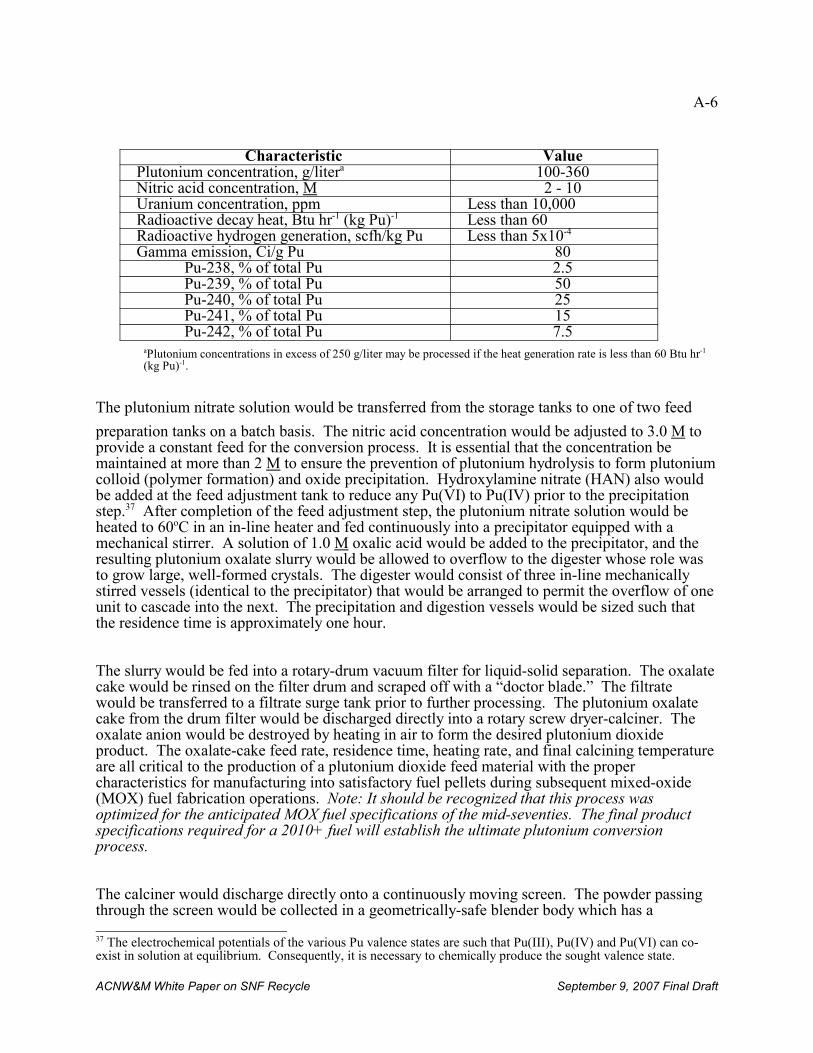
A-6
37 The electrochemical potentials of the various Pu valence states are such that Pu(III), Pu(IV) and Pu(VI) can co-exist in solution at equilibrium. Consequently, it is necessary to chemically produce the sought valence state.
ACNW&M White Paper on SNF Recycle September 9, 2007 Final Draft
Characteristic ValuePlutonium concentration, g/litera 100-360Nitric acid concentration, M 2 - 10Uranium concentration, ppm Less than 10,000Radioactive decay heat, Btu hr-1 (kg Pu)-1 Less than 60Radioactive hydrogen generation, scfh/kg Pu Less than 5x10⁻⁴
Gamma emission, Ci/g Pu 80Pu-238, % of total Pu 2.5Pu-239, % of total Pu 50Pu-240, % of total Pu 25Pu-241, % of total Pu 15Pu-242, % of total Pu 7.5
aPlutonium concentrations in excess of 250 g/liter may be processed if the heat generation rate is less than 60 Btu hr-1
(kg Pu)-1.
The plutonium nitrate solution would be transferred from the storage tanks to one of two feed
preparation tanks on a batch basis. The nitric acid concentration would be adjusted to 3.0 M toprovide a constant feed for the conversion process. It is essential that the concentration bemaintained at more than 2 M to ensure the prevention of plutonium hydrolysis to form plutoniumcolloid (polymer formation) and oxide precipitation. Hydroxylamine nitrate (HAN) also wouldbe added at the feed adjustment tank to reduce any Pu(VI) to Pu(IV) prior to the precipitationstep.37 After completion of the feed adjustment step, the plutonium nitrate solution would beheated to 60oC in an in-line heater and fed continuously into a precipitator equipped with amechanical stirrer. A solution of 1.0 M oxalic acid would be added to the precipitator, and theresulting plutonium oxalate slurry would be allowed to overflow to the digester whose role wasto grow large, well-formed crystals. The digester would consist of three in-line mechanicallystirred vessels (identical to the precipitator) that would be arranged to permit the overflow of oneunit to cascade into the next. The precipitation and digestion vessels would be sized such thatthe residence time is approximately one hour.
The slurry would be fed into a rotary-drum vacuum filter for liquid-solid separation. The oxalatecake would be rinsed on the filter drum and scraped off with a “doctor blade.” The filtratewould be transferred to a filtrate surge tank prior to further processing. The plutonium oxalatecake from the drum filter would be discharged directly into a rotary screw dryer-calciner. Theoxalate anion would be destroyed by heating in air to form the desired plutonium dioxideproduct. The oxalate-cake feed rate, residence time, heating rate, and final calcining temperatureare all critical to the production of a plutonium dioxide feed material with the propercharacteristics for manufacturing into satisfactory fuel pellets during subsequent mixed-oxide(MOX) fuel fabrication operations. Note: It should be recognized that this process wasoptimized for the anticipated MOX fuel specifications of the mid-seventies. The final productspecifications required for a 2010+ fuel will establish the ultimate plutonium conversionprocess.
The calciner would discharge directly onto a continuously moving screen. The powder passingthrough the screen would be collected in a geometrically-safe blender body which has a
A-7
ACNW&M White Paper on SNF Recycle September 9, 2007 Final Draft
maximum capacity of 40 kg of plutonium as plutonium oxide. The over-size product would passoff the top of the screen into a collection hopper. This hopper periodically would be emptiedinto a grinder which would reduce the particle size to meet the product specification. Thegrinder would empty into an identical 40-kg blender. The ground plutonium oxide would berecycled to either the top of the screen or to the dryer-calciner. These operations are especially“dirty” in that they produce a plutonium dioxide dust that is difficult to contain and handle.
Plutonium Sampling and Storage
A blender would receive nominally 32 kg of plutonium oxide, as indicated by a weighingelement beneath the blender. To change the vessel, it would be remotely valved-off andtransferred to the blending stand. The full blender body would be rotated about its radial centeruntil completion of blending. The powder would be sampled and the samples analyzed todetermine properties and insure homogeneity. The plutonium would be held in the blender bodyuntil the analytical results were received. Plutonium dioxide not meeting the productspecifications would be either recycled or loaded-out and held for future re-work.
The blended powder in the blender body would be transferred to the powder load-out standwhere the contents of the blender would be discharged into four product canisters, each holdingnominally 8 kg of plutonium oxide. The canister covers would be installed, each canister wouldbe sealed, and the outer surface would be decontaminated. Four product canisters would beloaded into a pressure vessel that would double as a storage container and primary containmentvessel during shipment. The pressure vessels (which were never built) were to be vented througha 3-stage HEPA filter. The loaded pressure vessel would be placed either in the storage vault orinto a shipping container for off-site shipment (if the MOX fuel fabrication plant were co-locatedwith the reprocessing/recycling facility, off-site shipment would not be necessary).
Recycle Streams
Filtrate from the vacuum drum would be collected in the filtrate surge tank where gas and liquidwould be separated. The gas would be routed to the vacuum pump. The majority of the gaseousoutput of the vacuum pump would be recycled to the vacuum drum filter. A small amount of thegas would be bled to the vessel off-gas system.
The liquid from the filtrate surge tanks would be pumped through cartridge-type secondaryfilters into the filtrate evaporator feed tank. The filtrate would be transferred from the filtrateevaporator feed tank by air lift into the filtrate evaporator. In the evaporator, the filtrate wouldbe distilled sufficiently for destruction of the oxalic acid and to reduce the volume of solutioncontaining plutonium.
The residue from the evaporator would be sequentially cooled, passed through another secondarycartridge-type filtration step to remove any possible solid (normally not expected), and thencollected in the concentrate catch tank. The filtrate concentrate then would be transferred by jetto the concentrate sample tank where it would be sampled. If analyses indicated the presence ofoxalic acid, it could be destroyed by returning it to the filtrate evaporator feed tank for
A-8
ACNW&M White Paper on SNF Recycle September 9, 2007 Final Draft
reprocessing or by addition of acidified potassium permanganate in the sample tank. Thecontents of the sample tank also would be returned to the evaporator feed tank if the presence ofsolids containing plutonium was detected. When sampling indicates the Pu content/mixture issatisfactory, the concentrate would be transferred to a storage tank from which it would bepumped to the Separations Facility for plutonium recovery.
The evaporator overhead would be condensed, combined with condensate from the off-gassystem, and filtered with cartridge-type filters to remove any possible solids. The distillatewould be collected in the distillate catch tank from which it would be transferred batch-wise tothe distillate sample tank. Depending on analyses, the distillate could be transferred to theevaporator feed tank for reprocessing, the concentrate storage tank when containing recoverableplutonium, or the distillate storage tank. From the distillate storage tank, the distillate could betransferred to the Separations Facility for acid recovery.
Waste Treatment
A typical commercial reprocessing/recycling plant of the 1970s generated gaseous, liquid andsolid waste, as would any modern day plant. Continuing with the example of the 1500 MTU/ydesigned separations capacity of the BNFP, the waste treatment specifications were as follows.
Low-level Liquid Wastes
At the BNFP low-level aqueous liquid waste was planned to be released into local area streamsat the rate of about 2,000 gallons per minute (at full nominal rated operation). Maximum releasetemperature was 850F with essentially no radioactivity and only water treatment chemicals in thewater.
High-level Liquid Wastes
High-level liquid waste was to be solidified after a minimum of five years of tank storage andtransported to a federal repository within 10 years of generation. The BNFP initially constructedtwo 300,000 gallon storage tanks, manufactured of 304L stainless steel, double-walled anddesigned with internal stainless steel cooling coils. Relevant design data on tank contents arenoted below:
Activity: 1.80 x 10⁴ Ci/gallon
Acid concentration: 1 - 5M HNO3
Temperature: 1400 F
Heat generation rate: 72,000 BTU/hrCMTU
Each cylindrical high-level liquid waste tank was 16.5 m in diameter by 6.1 m high and wascontained within an underground cylindrical concrete vault lined with stainless steel. Each vault
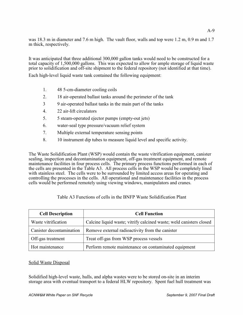
A-9
ACNW&M White Paper on SNF Recycle September 9, 2007 Final Draft
was 18.3 m in diameter and 7.6 m high. The vault floor, walls and top were 1.2 m, 0.9 m and 1.7m thick, respectively.
It was anticipated that three additional 300,000 gallon tanks would need to be constructed for atotal capacity of 1,500,000 gallons. This was expected to allow for ample storage of liquid wasteprior to solidification and off-site shipment to the federal repository (not identified at that time).
Each high-level liquid waste tank contained the following equipment:
1. 48 5-cm-diameter cooling coils
2. 18 air-operated ballast tanks around the perimeter of the tank
3 9 air-operated ballast tanks in the main part of the tanks
4. 22 air-lift circulators
5. 5 steam-operated ejector pumps (empty-out jets)
6. water-seal type pressure/vacuum relief system
7. Multiple external temperature sensing points
8. 10 instrument dip tubes to measure liquid level and specific activity.
The Waste Solidification Plant (WSP) would contain the waste vitrification equipment, canistersealing, inspection and decontamination equipment, off-gas treatment equipment, and remotemaintenance facilities in four process cells. The primary process functions performed in each ofthe cells are presented in the Table A3. All process cells in the WSP would be completely linedwith stainless steel. The cells were to be surrounded by limited access areas for operating andcontrolling the processes in the cells. All operational and maintenance facilities in the processcells would be performed remotely using viewing windows, manipulators and cranes.
Table A3 Functions of cells in the BNFP Waste Solidification Plant
Cell Description Cell Function
Waste vitrification Calcine liquid waste; vitrify calcined waste; weld canisters closed
Canister decontamination Remove external radioactivity from the canister
Off-gas treatment Treat off-gas from WSP process vessels
Hot maintenance Perform remote maintenance on contaminated equipment
Solid Waste Disposal
Solidified high-level waste, hulls, and alpha wastes were to be stored on-site in an interimstorage area with eventual transport to a federal HLW repository. Spent fuel hull treatment was
A-10
38 CEQ stands for Council on Environmental Quality.
ACNW&M White Paper on SNF Recycle September 9, 2007 Final Draft
to be optimized (e.g., hulls would be compacted or melted) in order to minimize overall capitaland/or operating costs. Because of the BNFP site location, transport may have been by truck,rail or inter-modal (including barge from site to port and thence by rail or truck to therepository).
Low-level solid waste would be disposed of at a licensed low-level waste facility. At the BNFPfacility, such disposal was simplified as the Chem-Nuclear Barnwell low-level waste site wasimmediately adjacent to the facility. While minimizing transportation costs all other relevantregulatory requirements needed to be met.
Off-Gas System
For the principal plant off-gases the initially projected release rates were:
1. Iodine
129I: 1.4 x 10⁻⁶ Ci/sec (99.9%+ % retained in plant)
131I: 1.1 x 10⁻⁵ Ci/sec (99.9%+ % retained in plant)
2. Krypton85Kr: 4.3 x 10⁻¹ Ci/sec (no recovery facilities were planned in the design beinginitially licensed)
3. Tritium3H: 1.8 x 10⁻² Ci/sec (no recovery facilities were planned in the design beinginitially licensed)
4. NOx: 200 pounds/hr. [release concentration less than 150 ppm (at top of stack)]
At the time, these releases were acceptable. However, as these earlier designs proceededthrough their review, agreement was reached with the CEQ38 that an effort would be made tominimize krypton and tritium releases, even though, at the time capturing these gases was notrequired. Cryogenic systems were considered and were being evaluated until INFCE started andthe concomitant ban on reprocessing was invoked which halted further commercial reprocessingdevelopment activity.
Nuclear material and quality control groups
The facility organization will normally include a nuclear material control group which will haveresponsibility for developing and carrying out an accounting plan. In addition, a facility is likelyto have an independent quality control group to assure compliance with the requirementsimposed on the facility.
The basic accounting method developed at NFS is conventional material balance accounting.
A-11
ACNW&M White Paper on SNF Recycle September 9, 2007 Final Draft
The facility is divided into a number of material balance areas, and all of the movements ofmaterials into and out of these areas are measured and recorded. At periodic intervals theinventory of materials in each of the areas is measured and a material balance is "closed". During each material balance period, the sum of the initial inventory in an area and the inputsduring the period should equal the sum of the final inventory and outputs. Any discrepancy islabeled as "material unaccounted for"or "inventory difference". If the discrepancy exceedsvalues which might be expected to result from measurement uncertainties, then further measuresare undertaken to attempt to identify the source or sources.
The material balance areas used for internal accounting purposes may not coincide with thoserequired for national or international safeguards systems. At NFS there were eight areasdesignated for internal accounting. These areas are:
• Fuel Receiving and Storage
• Mechanical Processing and Dissolution
• Input Accountability and Feed Adjustment
• Process Product Storage
• Shipment
• Waste Treatment
• Underground Waste Storage
• Analytical Laboratories
Several of these areas may be treated as one for accounting purposes under national orinternational safeguards systems.
Records
1. Fuel Receipt Form -- This form includes information on each fuel assembly provided bythe shipper including calculated uranium and plutonium content based on fuel fabricatorand reactor operating history data.
2. Fuel Storage Record -- This record is the canister number and pool storage location ofeach fuel assembly received. This information is also maintained on a status board.
3. Feed Magazine Loading Record and Shear Operating Record – These record themovement of material within the process mechanical cell and removal of assembliesfrom the storage
4. General Purpose Cell Record -- This is used to record the storage of chopped fuel,movement to dissolution, and any pumping from the cell sump.
A-12
ACNW&M White Paper on SNF Recycle September 9, 2007 Final Draft
5. Leached Hull Record -- This records the gross weight, tare weight, net weight, samplingcode and removal date of drums containing leached hulls.
6. Input Accountability Record -- This form records the instrument readings for the inputaccountability tank loading and the input sample identification.
7. Liquid Waste and Product Storage Tank Measurements -- These record the instrumentreadings and sample identification fo r the various process accountability vessels.
8. Plutonium or High Enrichment U Product Load-out Record – These record the gross andnet weights of the product load-out containers as well as their storage locations.
9. Analytical Services Form -- This records the sample identification and analytical results.
10. Inventory Record -- This form is used to record the instrument readings and sampleidentification for in-process material in various vessels at the end of each processingcampaign.
11. Material Status Report -- This is a consolidated inventory record which is prepared everythree months.
12. Shipping Form -- This is used to record accounting data on material which is shippedfrom the NFS facility.
Analyses on accountability samples
The analyses performed on accountability samples include : total Uranium, total plutonium,isotopic plutonium, isotopic uranium, and density. The techniques used include : massspectrometry, amperometric titration, isotopic dilution, alpha counting, high resolution gamma
spectroscopy, and various other chemical analysis techniques. The analysis of samples from theinput accountability and feed adjustment tank are particularly important for accounting purposes.
The input plutonium concentration is determined by an isotopic dilution technique. The inputsamples are diluted, spiked with 242Pu (or sometimes 244Pu), purified by ion exchange and thenanalyzed with a mass spectrometer. To determine the isotopic weight percentages, un-spikedsamples are analyzed with a mass spectrometer. Similar techniques are used for uranium measurements, but 235U or 233U is used as the spiking isotope.
Similar techniques are used for the assessment of output solutions with the exception thattitration techniques are normally used to determine the uranium and plutonium concentrations. In addition to assessing the product solutions, the waste materials are also assayed for uraniumand plutonium content.
ACNW&M White Paper on SNF Recycle September 9, 2007 Final Draft
APPENDIX B: Decay Heat in Spent Fuel
B-1
ACNW&M White Paper on SNF Recycle September 9, 2007 Final Draft
There are advantages and disadvantages to reprocessing relatively short-cooled spent fuel. Advantages accrue with respect to heat reduction in the waste as additional actinides andselected fission products are removed prior to storage of the waste. Advantages relate toreducing the amount of spent fuel stored and reduction of the amount of heat-producing 241Amwhen the actinides are recovered for transmutation. This reduces the need for spent fuel storagefacilities and storage casks. It also reduces the potential risk of proliferation or of terrorist attackon the stored spent fuel.
The disadvantages of reprocessing relatively short-cooled spent fuel are related to the necessityto handle more highly radioactive fuel, which increases the potential hazards and adds to thecomplexity and cost of the reprocessing plant and processes. Fig. B1 [OECD, 2006] shows thecontributions of selected actinides and fission products to heat generation rate in waste as afunction of decay time for fuel irradiated to 51 GWd/MTIHM and Fig. B2 [OECD, 2006] showsthe advantage of removing the actinides 238Pu and 241Am with respect to decay heat reduction inwaste as a function of decay time.
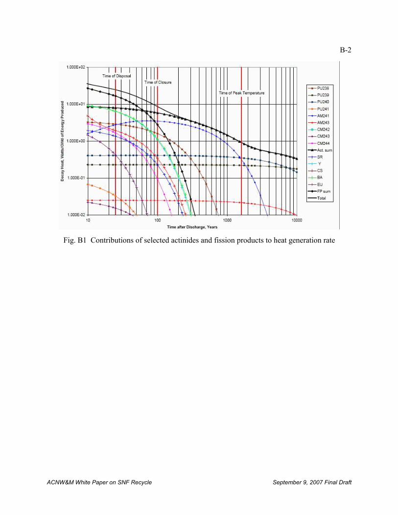
B-2
ACNW&M White Paper on SNF Recycle September 9, 2007 Final Draft
Fig. B1 Contributions of selected actinides and fission products to heat generation rate
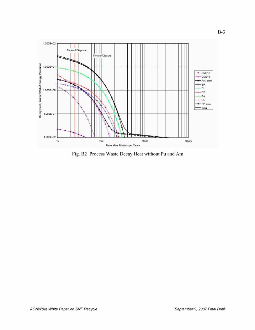
B-3
ACNW&M White Paper on SNF Recycle September 9, 2007 Final Draft
Fig. B2 Process Waste Decay Heat without Pu and Am
ACNW&M White Paper on SNF Recycle September 9, 2007 Final Draft
APPENDIX C: Committee Letters Related to Risk-Informed Activities and ProbabilisticRisk Assessment
C-1
ACNW&M White Paper on SNF Recycle September 9, 2007 Final Draft
• ACNW&M letter dated May 2, 2006, from Michael T. Ryan, Chairman, ACNW&M toNils J. Diaz, Chairman USNRC, Subject: Risk-Informed Decision-Making for NuclearMaterials and Wastes.
• ACNW&M letter dated May 3, 2004 from B. John Garrick, Chairman, ACNW&M toNils J. Diaz, Chairman USNRC, Subject: Risk Insights Baseline Report.
• ACNW&M letter dated August 13, 2003 from B. John Garrick, Chairman, ACNW&M to Nils J. Diaz, Chairman USNRC, Subject: High Level Waste: Risk-SignificanceRanking of Agreements and the Use of Risk Information to Resolve Issues.
• ACNW&M letter dated July 2, 2002 from George M. Hornberger, Chairman,ACNW&M to Richard A. Meserve, Chairman USNRC, Subject: The High-LevelProgram Risk Insights Initiative.
• ACNW&M letter dated April 29, 2002 from George M. Hornberger, Chairman,ACNW&M to William D. Travers, Executive Director for Operations, USNRC, Subject: Response to Letter Dated March 6, 2002 Concerning Risk-Informed Activitiesin the Office of Nuclear Material Safety and Safeguards.
• ACNW&M letter dated January 14, 2002 from George M. Hornberger, Chairman,ACNW&M to Richard A. Meserve, Chairman USNRC, Subject: Risk-InformedActivities in the Office of Nuclear Material Safety and Safeguard
• ACNW&M letter dated June 29, 2001 from B. John Garrick, Chairman, ACNW&M toRichard A. Meserve, Chairman USNRC, Subject: Risk-Informed, Performance-BasedRegulation of Waste Management and Decommissioning.
• ACNW&M letter dated July 27, 2000 from B. John Garrick, Chairman, ACNW&M toRichard A. Meserve, Chairman USNRC, Subject: Development of Risk-InformedRegulation in the Office of Nuclear Material Safety and Safeguards.
• ACNW&M letter dated March 26, 1998 from B. John Garrick, Chairman, ACNW&M to Shirley Ann Jackson, Chairman USNRC, Subject: Risk-Informed, Performance-BasedRegulation in Nuclear Waste Management.
• ACNW&M letter dated October 31, 1997 from B. John Garrick, Chairman, ACNW&M to Shirley Ann Jackson, Chairman USNRC, Subject: Application of Probabilistic RiskAssessment Methods to Performance Assessment in the NRC High-Level WasteProgram.
ACNW&M White Paper on SNF Recycle September 9, 2007 Final Draft
APPENDIX D: 10 CFR Part 55 Operators Licenses
D-1
ACNW&M White Paper on SNF Recycle September 9, 2007 Final Draft
As written 10 CFR Part 55 applies to utilization facilities (e.g., nuclear reactors) and not toreprocessing plants. Key provisions concerning operator’s licenses are as follows:
“(a) The applicant shall:
(1) Complete NRC form 398, “Personal Qualification Statement – Licensee,” which can beobtained by writing the Office of Information Services, U.S. Nuclear RegulatoryCommission, Washington, D.C. 20555-0001, by calling (301) 415-5877, or by visitingthe NRC’s Web site at http:www.nrc.gov and selecting forms from the index found onthe home page;
(2) File an original of NRC Form 398, together with the information required in paragraphs(a) (3), (4), (5) and (6) of this section, with the appropriate Regional Administrator;
(3) Submit a written request from an authorized representative of the facility licensee bywhich the applicant will be employed that the written examination and operating test beadministered to the applicant;
(4) Provide evidence that the applicant has successfully completed the facility licensee’srequirements to be licensed as an operator or senior operator and of the facility licensee’sneed for an operator or a senior operator to perform assigned duties. An authorizedrepresentative of the facility licensee shall certify this evidence on Form NRC-398. Thiscertification must include details of the applicant’s qualifications, and details on coursesof instruction administered by the facility licensee, and describe the nature of the trainingreceived at the facility, and the startup and shutdown experience received. In lieu ofthese details, the Commission may accept certification that the applicant has successfullycompleted a Commission approved training program that is based on a systems approachto training and that uses a simulation facility acceptable to the Commission under Section55.45(b) of this part;
(5) Provide evidence that the applicant, as a trainee, has successfully manipulated thecontrols of either the facility for which a license is sought or a plant-referenced simulatorthat meets the requirements of 55.46 c. At a minimum, five significant controlmanipulations must be performed that affect reactivity or power level (this requirement isobviously directed to operating a nuclear reactor, not to a reprocessing plant). Controlmanipulations performed on the plant-referenced simulator may be chosen from arepresentative sampling of the control manipulations and plant evolutions described in55.59 of this part, as applicable to the design of the plant for which the licenseapplication is submitted. For licensed operators applying for a senior operator license,certification that the operator has successfully operated the controls of the facility as alicensed operator shall be accepted; and
(6) Provide certification by the facility licensee of medical condition and general health onForm NRC-396, to comply with Sections 55.21, 55.23 and 55.3(a)(1).”
D-2
ACNW&M White Paper on SNF Recycle September 9, 2007 Final Draft
A copy of NRC Form-398 is to be attached for information. It should be noted that theserequirements have evolved over the past several decades and are much more detailed than the10CFR 55 rules in existence 30 years ago. It should also be noted that at this time there is no“simulation facility acceptable to the Commission” for a commercial reprocessing/recyclingplant.
ACNW&M White Paper on SNF Recycle September 9, 2007 Final Draft
APPENDIX E. Radionuclide Distribution Among UREX +1a Process Streams
E-2
ACNW&M White Paper on SNF Recycle September 9, 2007 Final Draft
The basis for the following discussion is one MTIHM of PWR fuel irradiated to 33GWd/MTIHM. The radiological characteristics of the process streams are based on anORIGEN2 calculation documented in ADAMS (ML072820458).
Head End Process Step
Noble Metal Fission Yields from one MTIHM @ 33 Gwd/te
Tc: Grams, 774; Curies, 13.1
Ru: Grams, 2190; Curies, 0.0185
Pd: Grams, 1385; Curies, 0.113
Mo: Grams, 3351; Curies, Stable (HF dissolves ~ 0.98 of Zr/Mo, leaving ~ 67 g)
Rh: Grams, 468; Curies, 0.0216
TOTAL initial solids before dissolution: 8168 grams (or 4884 grams if Mo is partially dissolvedas Zr/Mo); TOTAL Curies: 13.25
Solids amounts increase faster than linearly with fuel burnup.
461.4 Kg HM per 154.5 Kg assembly hardware: 335 Kg hardware/MTIHM. 2.874 Kg and 2.00Ci noble metals in 335 Kg (per 1 MTIHM) hardware assuming all noble metals are combinedwith hardware.
Composition of solids in dissolver after dissolution
References: “X-Ray Diffraction Studies on Irradiated Nuclear Fuels,” H. Kleykamp and R.Pejsa, Journal of Nuclear Materials 124 56-3, 1984; personal communication from D. O.Campbell (retired from ORNL); “Flowsheet and Source Terms for Radioactive WasteProjections,” C. Forsberg et al., ORNL/TM-8462, p. 96, March 1985.
Element Range, %
Tc 8 -12 (assume 15 %): 116 grams; 1.97 Ci
Ru 27-47 (assume 50 %): 1095 grams; 0.01 Ci
Pd 10-18 (assume 20 %): 277 grams; 0.023 Ci
Mo 16-41 (assume 40%): 1340 grams; 0.000 Ci
Rh 6-11 (assume 10 %): 46.8 grams; 0.002 Ci
U: 0.05 (assume 0.0005 fraction remains undissolved in sheared fuel); 478Grams
TOTAL: grams 3353; TOTAL Ci: 2.00
E-3
ACNW&M White Paper on SNF Recycle September 9, 2007 Final Draft
Fraction Tc in UREX Process feed stream: 0.85
Fraction Tc in dissolver residues combined with cladding hulls: 0.15
Fraction Tc in U product: 0.0001 (assumption)
Using three Reillex HPQ columns in series no Tc remained in the U product stream. All the Tcremained on the third resin column.
Fraction Tc in fission product waste: none (assumes all is combined with hulls)
Fraction Tc in TRU product: 0.0001 (assumption)
Volatiles and Gases
References: Light Water Reactor Nuclear Fuel Cycle, Eds. R. G. Wymer and B. L. Vondra, CRCPress, 1981; ORNL-/TM-5987, “LWR Fuel Reprocessing and Recycle Program
Quarterly Report for Period April 1 to June 30, 1977, B. L. Vondra; “Alternate Fuel CycleTechnologies Program Quarterly Report for Period July 1 to September 30, 1977,” ORNL/TM-6076, B. L. Vondra; “Study on Gaseous Effluent Treatment for Dissolution Step Nuclear FuelReprocessing,” H. Mineo et al., WM’02 Conference, February 24-28, 2002, AZ
Voloxidation releases:
1.00 fraction 3H from the fuel
0.06 fraction Kr
0.01 fraction I
0.5 fraction 14C
Assume 1.000 fraction of all volatiles and gases left in fuel after voloxidation goes to dissolveroff-gas.
3H:
0.0208 grams (fission + activation); 201 Ci (fission + activation)
Fraction solidified as water in solid waste: 0.59 (fraction assuming no voloxidation)
Fraction in Zircaloy cladding: (0.41 if no voloxidation); 0.000 if voloxidation
39 cubic centimeters as gas at 1 atmosphere and 0 °C. (STP)
Kr
1.59 grams total of all isotopes (42.4 cubic centimeters at STP)
1847 curies 85Kr (the only curie source of importance)
Fraction captured: 0.85 (assuming capture from voloxidation and from the dissolver off-gas)
Storage may be in cylinders, on solid sorbents, or by more exotic means such as ionimplantation.
E-4
ACNW&M White Paper on SNF Recycle September 9, 2007 Final Draft
Xe
5.35 grams total of all isotopes (894 cubic centimeters at STP)
All isotopes are stable
Xe capture is determined by the removal process chosen, and can approach that for Kr, i.e., 0.85fraction.
Storage may be in cylinders, or it may be released since it is essentially not radioactive.
I
“Alternate Fuel Cycle Technologies Program Quarterly Report for Period July 1 to September30, 1977,” ORNL/TM-6076, B. L. Vondra; “Environmental Radiation Requirements for NormalOperations in the Uranium Fuel Cycle,” 40CFR190, Vol 1, p. 45
127I: 5.594E+01 grams; stable129I: 1.800E+02 grams; 3.179E-02 Ci
TOTAL grams: 2.36E+02; TOTAL Ci: 3.179E-02
129I
Fraction to off-gas from voloxidation: 0.01
Fraction in solids in dissolver: 0.022 (as AgI and PdI2)
Fraction of I in PdI2 (decomposes in vitrifier and goes to off-gas): 0.011
Fraction of I in AgI (stable) and goes with noble metals to hull wastes: 0.11
Fraction retained in dissolver solution: 0.0072
Fraction to off-gas from dissolver solution: 0.965
Fraction in off-gas captured and made into solid waste: 0.995
Bulk density of AgNO3/silica gel: 0.719 (this absorbant will be used in Japan’s Rokkashoreprocessing plant); the Iodox Process produces Ba(IO3)2 which is a potential wasteform.
14C
2.632E-05 g; 1.88E-06 moles (0.042 cubic centimeters at STP)
1.174E-04 Ci
Fraction from voloxidation to off-gas as CO2: 0.05
Fraction from dissolver to off-gas as CO2: 0.89
Fraction going to UREX process step: 0.06
Fraction going to CD-PEG: 1.00
Fraction going to TRUEX: 1.00
Fraction going to TALSPEAK: 1.00
E-5
ACNW&M White Paper on SNF Recycle September 9, 2007 Final Draft
Fraction going to F.P. waste stream: 1.00
Fraction released in F.P. waste vitrification step: 0.06
Fraction captured in off-gas trapping system: 0.96
CO2 collected in CaCO3 solution
UREX Process step
Fraction Tc in U product: 0.0001
Fraction U in U product: 0.997
Fraction U in raffinate: 0.003
Rare earths fraction to CCD-PEG: 0.9975
CCD-PEG Process step
Cs133Cs: 1.132E+3 grams; stable134Cs: 2.616E-2 grams; 3.386E+01 Ci135Cs: 3.013E+2 grams; 0.347 Ci137Cs: 6.713E+2 grams; 5.842 E+04
TOTAL grams Cs: 2.105E+03; Total Ci: 5.845E+04 Ci
Fraction Cs to product: 0.9984
137Cs
Reference: “Lab-Scale Demonstration of the UREX+1a Process Using Spent Fuel,” C. Pereira etal., WM’07 Symposium, February 25-March1, 2007
Fraction to U product: insignificant
Fraction to CCD-PEG: 1.00
Grams in CCD-PEG product: 670
Curies in CCD-PEG product: 5.83E+04
Fraction to TRUEX: 0.0016
E-6
ACNW&M White Paper on SNF Recycle September 9, 2007 Final Draft
Sr86Sr: 4.038E-01 grams; stable88Sr: 3.504E+02 grams; stable90Sr: 2.940E+02 grams; 4.012E+04 Ci
TOTAL grams Sr: 6.48E+02; TOTAL Ci: 4.012E+04
90Sr
Reference: “Lab-Scale Demonstration of the UREX+1a Process Using Spent Fuel,” C. Pereira etal., WM’07 Symposium, February 25-March1, 2007
Fraction to U product: insignificant
Grams in CCD-PEG product: 293
Curies in CCD-PEG Product: 3.98E+04
Fraction to CCD-PEG product: 0.9984
Fraction to TRUEX: 0.0016
U
U: Fraction to TRUEX: 1.000
TRUEX Process Step
Rare Earths
Reference: “Metal Recovery Plant Activities During FY 1956,” ORNL-2235; “Lab-ScaleDemonstration of the UREX+1a Process Using Spent Fuel,” C. Pereira et al., WM’07, Symposium, February 25-March 1, 2007, Tucson, AZ
DF (total RE β): ~400 for uranium product; fraction in U product: 0.0025
Rare earths fraction to CCD-PEG: 0.9975
Rare earths fraction to TRUEX: 0.9993
Rare earth grams to TRUEX
Rare earths fraction to TALSPEAK: 0.9991
Rare earths fraction to waste: 0.99
U
U fraction to TALSPEAK: 1.000 (assumed)
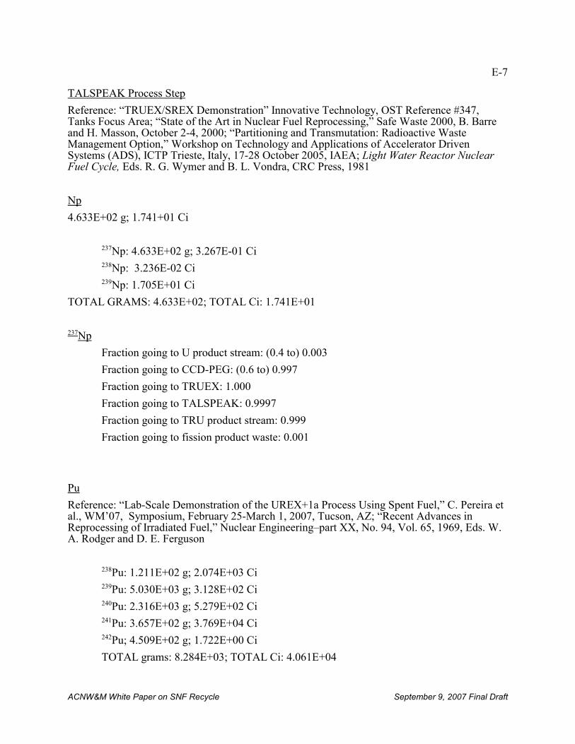
E-7
ACNW&M White Paper on SNF Recycle September 9, 2007 Final Draft
TALSPEAK Process Step
Reference: “TRUEX/SREX Demonstration” Innovative Technology, OST Reference #347,Tanks Focus Area; “State of the Art in Nuclear Fuel Reprocessing,” Safe Waste 2000, B. Barreand H. Masson, October 2-4, 2000; “Partitioning and Transmutation: Radioactive WasteManagement Option,” Workshop on Technology and Applications of Accelerator DrivenSystems (ADS), ICTP Trieste, Italy, 17-28 October 2005, IAEA; Light Water Reactor NuclearFuel Cycle, Eds. R. G. Wymer and B. L. Vondra, CRC Press, 1981
Np
4.633E+02 g; 1.741+01 Ci
237Np: 4.633E+02 g; 3.267E-01 Ci238Np: 3.236E-02 Ci239Np: 1.705E+01 Ci
TOTAL GRAMS: 4.633E+02; TOTAL Ci: 1.741E+01
237Np
Fraction going to U product stream: (0.4 to) 0.003
Fraction going to CCD-PEG: (0.6 to) 0.997
Fraction going to TRUEX: 1.000
Fraction going to TALSPEAK: 0.9997
Fraction going to TRU product stream: 0.999
Fraction going to fission product waste: 0.001
Pu
Reference: “Lab-Scale Demonstration of the UREX+1a Process Using Spent Fuel,” C. Pereira etal., WM’07, Symposium, February 25-March 1, 2007, Tucson, AZ; “Recent Advances inReprocessing of Irradiated Fuel,” Nuclear Engineering–part XX, No. 94, Vol. 65, 1969, Eds. W.A. Rodger and D. E. Ferguson
238Pu: 1.211E+02 g; 2.074E+03 Ci239Pu: 5.030E+03 g; 3.128E+02 Ci240Pu: 2.316E+03 g; 5.279E+02 Ci241Pu: 3.657E+02 g; 3.769E+04 Ci242Pu; 4.509E+02 g; 1.722E+00 Ci
TOTAL grams: 8.284E+03; TOTAL Ci: 4.061E+04
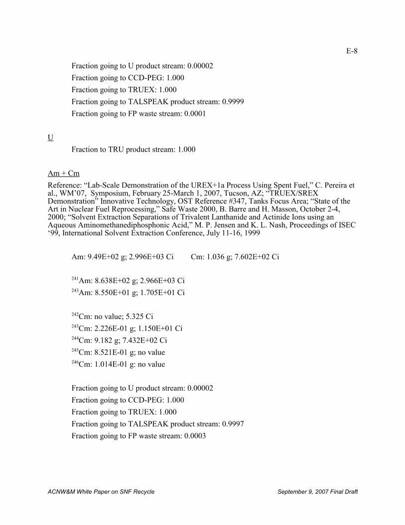
E-8
ACNW&M White Paper on SNF Recycle September 9, 2007 Final Draft
Fraction going to U product stream: 0.00002
Fraction going to CCD-PEG: 1.000
Fraction going to TRUEX: 1.000
Fraction going to TALSPEAK product stream: 0.9999
Fraction going to FP waste stream: 0.0001
U
Fraction to TRU product stream: 1.000
Am + Cm
Reference: “Lab-Scale Demonstration of the UREX+1a Process Using Spent Fuel,” C. Pereira etal., WM’07, Symposium, February 25-March 1, 2007, Tucson, AZ; “TRUEX/SREXDemonstration” Innovative Technology, OST Reference #347, Tanks Focus Area; “State of theArt in Nuclear Fuel Reprocessing,” Safe Waste 2000, B. Barre and H. Masson, October 2-4,2000; “Solvent Extraction Separations of Trivalent Lanthanide and Actinide Ions using anAqueous Aminomethanediphosphonic Acid,” M. P. Jensen and K. L. Nash, Proceedings of ISEC‘99, International Solvent Extraction Conference, July 11-16, 1999
Am: 9.49E+02 g; 2.996E+03 Ci Cm: 1.036 g; 7.602E+02 Ci
241Am: 8.638E+02 g; 2.966E+03 Ci243Am: 8.550E+01 g; 1.705E+01 Ci
242Cm: no value; 5.325 Ci243Cm: 2.226E-01 g; 1.150E+01 Ci244Cm: 9.182 g; 7.432E+02 Ci245Cm: 8.521E-01 g; no value246Cm: 1.014E-01 g: no value
Fraction going to U product stream: 0.00002
Fraction going to CCD-PEG: 1.000
Fraction going to TRUEX: 1.000
Fraction going to TALSPEAK product stream: 0.9997
Fraction going to FP waste stream: 0.0003
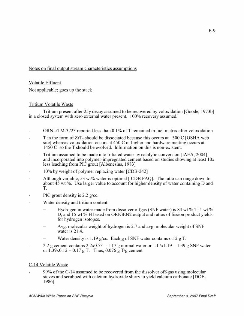
E-9
ACNW&M White Paper on SNF Recycle September 9, 2007 Final Draft
Notes on final output stream characteristics assumptions
Volatile Effluent
Not applicable; goes up the stack
Tritium Volatile Waste
- Tritium present after 25y decay assumed to be recovered by voloxidation [Goode, 1973b] in a closed system with zero external water present. 100% recovery assumed.
- ORNL/TM-3723 reported less than 0.1% of T remained in fuel matrix after voloxidation
- T in the form of ZrT2 should be dissociated because this occurs at ~300 C [OSHA website] whereas voloxidation occurs at 450 C or higher and hardware melting occurs at1450 C so the T should be evolved. Information on this is non-existent.
- Tritium assumed to be made into tritiated water by catalytic conversion [IAEA, 2004]and incorporated into polymer-impregnated cement based on studies showing at least 10xless leaching from PIC grout [Albenesius, 1983]
- 10% by weight of polymer replacing water [CDB-242]
- Although variable, 53 wt% water is optimal [ CDB FAQ]. The ratio can range down toabout 45 wt %. Use larger value to account for higher density of water containing D andT.
- PIC grout density is 2.2 g/cc.
- Water density and tritium content
= Hydrogen in water made from dissolver offgas (SNF water) is 84 wt % T, 1 wt %D, and 15 wt % H based on ORIGEN2 output and ratios of fission product yieldsfor hydrogen isotopes.
= Avg. molecular weight of hydrogen is 2.7 and avg. molecular weight of SNFwater is 21.4.
= Water density is 1.19 g/cc. Each g of SNF water contains o.12 g T.
- 2.2 g cement contains 2.2x0.53 = 1.17 g normal water or 1.17x1.19 = 1.39 g SNF wateror 1.39x0.12 = 0.17 g T. Thus, 0.076 g T/g cement
C-14 Volatile Waste
- 99% of the C-14 assumed to be recovered from the dissolver off-gas using molecularsieves and scrubbed with calcium hydroxide slurry to yield calcium carbonate [DOE,1986].
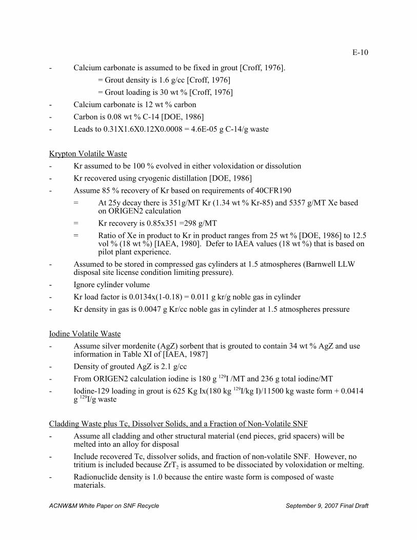
E-10
ACNW&M White Paper on SNF Recycle September 9, 2007 Final Draft
- Calcium carbonate is assumed to be fixed in grout [Croff, 1976].
= Grout density is 1.6 g/cc [Croff, 1976]
= Grout loading is 30 wt % [Croff, 1976]
- Calcium carbonate is 12 wt % carbon
- Carbon is 0.08 wt % C-14 [DOE, 1986]
- Leads to 0.31X1.6X0.12X0.0008 = 4.6E-05 g C-14/g waste
Krypton Volatile Waste
- Kr assumed to be 100 % evolved in either voloxidation or dissolution
- Kr recovered using cryogenic distillation [DOE, 1986]
- Assume 85 % recovery of Kr based on requirements of 40CFR190
= At 25y decay there is 351g/MT Kr (1.34 wt % Kr-85) and 5357 g/MT Xe basedon ORIGEN2 calculation
= Kr recovery is 0.85x351 =298 g/MT
= Ratio of Xe in product to Kr in product ranges from 25 wt % [DOE, 1986] to 12.5vol % (18 wt %) [IAEA, 1980]. Defer to IAEA values (18 wt %) that is based onpilot plant experience.
- Assumed to be stored in compressed gas cylinders at 1.5 atmospheres (Barnwell LLWdisposal site license condition limiting pressure).
- Ignore cylinder volume
- Kr load factor is 0.0134x(1-0.18) = 0.011 g kr/g noble gas in cylinder
- Kr density in gas is 0.0047 g Kr/cc noble gas in cylinder at 1.5 atmospheres pressure
Iodine Volatile Waste
- Assume silver mordenite (AgZ) sorbent that is grouted to contain 34 wt % AgZ and useinformation in Table XI of [IAEA, 1987]
- Density of grouted AgZ is 2.1 g/cc
- From ORIGEN2 calculation iodine is 180 g 129I /MT and 236 g total iodine/MT
- Iodine-129 loading in grout is 625 Kg Ix(180 kg 129I/kg I)/11500 kg waste form + 0.0414g 129I/g waste
Cladding Waste plus Tc, Dissolver Solids, and a Fraction of Non-Volatile SNF
- Assume all cladding and other structural material (end pieces, grid spacers) will bemelted into an alloy for disposal
- Include recovered Tc, dissolver solids, and fraction of non-volatile SNF. However, notritium is included because ZrT2 is assumed to be dissociated by voloxidation or melting.
- Radionuclide density is 1.0 because the entire waste form is composed of wastematerials.
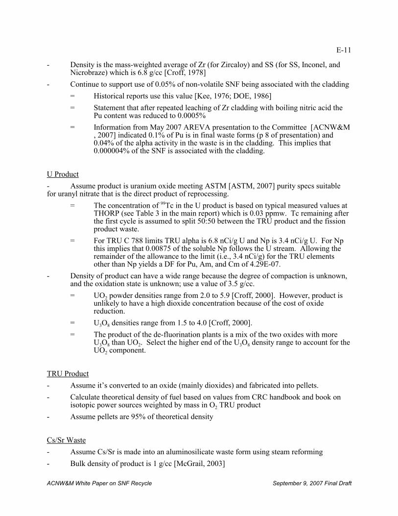
E-11
ACNW&M White Paper on SNF Recycle September 9, 2007 Final Draft
- Density is the mass-weighted average of Zr (for Zircaloy) and SS (for SS, Inconel, andNicrobraze) which is 6.8 g/cc [Croff, 1978]
- Continue to support use of 0.05% of non-volatile SNF being associated with the cladding
= Historical reports use this value [Kee, 1976; DOE, 1986]
= Statement that after repeated leaching of Zr cladding with boiling nitric acid thePu content was reduced to 0.0005%
= Information from May 2007 AREVA presentation to the Committee [ACNW&M, 2007] indicated 0.1% of Pu is in final waste forms (p 8 of presentation) and0.04% of the alpha activity in the waste is in the cladding. This implies that0.000004% of the SNF is associated with the cladding.
U Product
- Assume product is uranium oxide meeting ASTM [ASTM, 2007] purity specs suitablefor uranyl nitrate that is the direct product of reprocessing.
= The concentration of 99Tc in the U product is based on typical measured values atTHORP (see Table 3 in the main report) which is 0.03 ppmw. Tc remaining afterthe first cycle is assumed to split 50:50 between the TRU product and the fissionproduct waste.
= For TRU C 788 limits TRU alpha is 6.8 nCi/g U and Np is 3.4 nCi/g U. For Npthis implies that 0.00875 of the soluble Np follows the U stream. Allowing theremainder of the allowance to the limit (i.e., 3.4 nCi/g) for the TRU elementsother than Np yields a DF for Pu, Am, and Cm of 4.29E-07.
- Density of product can have a wide range because the degree of compaction is unknown,and the oxidation state is unknown; use a value of 3.5 g/cc.
= UO2 powder densities range from 2.0 to 5.9 [Croff, 2000]. However, product isunlikely to have a high dioxide concentration because of the cost of oxidereduction.
= U3O8 densities range from 1.5 to 4.0 [Croff, 2000].
= The product of the de-fluorination plants is a mix of the two oxides with moreU3O8 than UO2. Select the higher end of the U3O8 density range to account for theUO2 component.
TRU Product
- Assume it’s converted to an oxide (mainly dioxides) and fabricated into pellets.
- Calculate theoretical density of fuel based on values from CRC handbook and book onisotopic power sources weighted by mass in O2 TRU product
- Assume pellets are 95% of theoretical density
Cs/Sr Waste
- Assume Cs/Sr is made into an aluminosilicate waste form using steam reforming
- Bulk density of product is 1 g/cc [McGrail, 2003]
E-12
ACNW&M White Paper on SNF Recycle September 9, 2007 Final Draft
- Waste loading is 27% [Jantzen, 2002]
Fission Product Waste
- Base values on experience at DWPF
- Glass density 2.65 [Bibler, 2000]
- Waste loading 38% [Jantzen, 2004]