Embed Size (px)
Citation preview
Background Statement for SEMI Draft Document 3440C NEW STANDARD: TEST METHOD FOR PRESSURE TRANSDUCERS IN GAS DELIVERY SYSTEMS
Notice: This background statement is not part of the balloted item. It is provided solely to assist the recipient in
reaching an informed decision based on the rationale of the activity that preceded the creation of this Document.
Notice: Recipients of this Document are invited to submit, with their comments, notification of any relevant
patented technology or copyrighted items of which they are aware and to provide supporting documentation. In this
context, “patented technology” is defined as technology for which a patent has issued or has been applied for. In the
latter case, only publicly available information on the contents of the patent application is to be provided.
Background There are currently no standardized test methods or specifications for pressure measurement devices (transducers
and gauges) used in semiconductor process equipment and facilities distribution systems. There are documents from
ASME and ISA that can be readily adapted for use in this industry that will allow the users of these devices to
clearly and competitively analyze the performance characteristics from the different manufacturers. The rated
accuracy needs to be clearly defined as well as the design characteristics of these critical components. This activity
is similar to those already underway in the Facilities Committee for MFCs, valves, and regulators.
Additionally, the Facilities & Gases Committee has addressed the physical dimensions and interfaces of pressure
transducers in the Gas Box Components Task Force as well as the Surface Mount Task Force, the envelope
dimensions for pressure gauges has not been address and could be an additional activity for this task force.
Document 3440B was balloted in Cycle 2 of 2016 and failed due to a persuasive reject. Document 3440C
incorporated all negatives and comments and is being issues for Cycle 4 of 2016 for review at the next meeting.
Review and Adjudication Information
Task Force Review Committee Adjudication
Group: Pressure Measurement Task Force Facilities & Gases NA TC Chapter
Date: July 11, 2016 July 12, 2016
Time & Timezone: 14:00 – 16:00 PDT 9:00 AM – 12:00 Noon PDT
Location: San Francisco Marriott Marquis
780 Mission St.
San Francisco, CA 94103
San Francisco Marriott Marquis
780 Mission St.
San Francisco, CA 94103
City,
State/Country:
San Francisco, CA/USA San Francisco, CA/USA
Leader(s)/Authors: Yanli Chen (UCT)
Jeff Christian (Wika Instrument)
Mohamed Saleem (Fujikin)
Steve Lewis (LPCiminelli)
Standards Staff: Laura Nguyen ([email protected] ) Laura Nguyen ([email protected] )
This meeting’s details are subject to change, and additional review sessions may be scheduled if necessary. Contact
the task force leaders or Standards staff for confirmation.
Telephone and web information will be distributed to interested parties as the meeting date approaches. If you will
not be able to attend these meetings in person but would like to participate by telephone/web, please contact
Standards staff.
Check www.semi.org/standards on calendar of event for the latest meeting schedule.
This is a Draft Document of the SEMI International Standards program. No material on this page is to be construed as an official or adopted Standard or Safety Guideline. Permission is granted to reproduce and/or distribute this document, in whole or in part, only within the scope of SEMI International Standards committee (document development) activity. All other reproduction and/or distribution without the prior written consent of SEMI is prohibited.
Page 1 Doc. 3440C SEMI
Semiconductor Equipment and Materials International 3081 Zanker Road San Jose, CA 95134-2127 Phone: 408.943.6900, Fax: 408.943.7943
LE
TT
ER
BA
LL
OT
DRAFT Document Number: 3440C
Date: 4/20/2016
SEMI Draft Document 3440C NEW STANDARD: TEST METHOD FOR PRESSURE TRANSDUCERS USED IN GAS DELIVERY SYSTEMS
Purpose
The purpose of this Document is to outline the test methods for electronic pressure transducers used in gas delivery
systems for semiconductor processing.
Scope
This Document describes the procedures for testing the leak integrity, warm up time, voltage sensitivity,
inaccuracy, linearity, repeatability, hysteresis, reproducibility, thermal coefficient, drift, accelerated life cycle, and
proof pressure of pressure transducers with a full pressure range of 2757.9 KPa (400 psia) or less in gas delivery
systems.
NOTICE: SEMI Standards and Safety Guidelines do not purport to address all safety issues associated with their use.
It is the responsibility of the users of the Document to establish appropriate safety and health practices, and determine
the applicability of regulatory or other limitations prior to use.
Limitations
This Document does not cover the testing of absolute pressure measurement instruments, pressure switches or
mechanical pressure gauges, such as Bourdon tube pressure gauges.
Referenced Standards and Documents
SEMI Standards and Safety Guidelines
SEMI C59 — Specifications and Guidelines for Nitrogen
SEMI E27 — Standard for Mass Flow Controller and Mass Flow Meter Linearity
SEMI E28 — Guide for Pressure Specification of the Mass Flow Controller
SEMI E49 — Guide for High Purity and Ultrahigh Purity Piping Performance, Subassemblies, and Final Assemblies
SEMI E56 — Test Method for Determining Accuracy, Linearity, Repeatability, Short-Term Reproducibility,
Hysteresis, and Dead Band of Thermal Mass Flow Controllers
SEMI E89 — Guide for Measurement System Analysis (MSA)
SEMI F1 — Specification for Leak Integrity of High-Purity Gas Piping Systems and Components
SEMI F62 — Test Method for Determining Mass Flow Controller Performance Characteristics from Ambient and
Gas Temperature Effects
American National Standard1
ANSI/ISA-S51.1-1979 (R1993) — Process Instrumentation Terminology
1 American National Standards Institute
Headquarters: 1819 L Street, NW, Washington, DC 20036, USA. Telephone: 202.293.8020; Fax: 202.293.9287
New York Office: 11 West 42nd Street, New York, NY 10036, USA. Telephone: 212.642.4900; Fax: 212.398.0023
Website: www.ansi.org 2 The International Electrotechnical Commission (IEC)
3, rue de Varembé, CH-1211 Geneva 20, Switzerland. Email: [email protected]
Website:www.iec.ch
This is a Draft Document of the SEMI International Standards program. No material on this page is to be construed as an official or adopted Standard or Safety Guideline. Permission is granted to reproduce and/or distribute this document, in whole or in part, only within the scope of SEMI International Standards committee (document development) activity. All other reproduction and/or distribution without the prior written consent of SEMI is prohibited.
Page 2 Doc. 3440C SEMI
Semiconductor Equipment and Materials International 3081 Zanker Road San Jose, CA 95134-2127 Phone: 408.943.6900, Fax: 408.943.7943
LE
TT
ER
BA
LL
OT
DRAFT Document Number: 3440C
Date: 4/20/2016
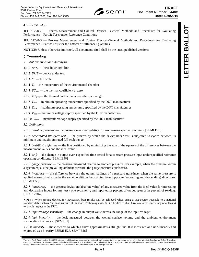
IEC Standard2
IEC 61298-2 — Process Measurement and Control Devices - General Methods and Procedures for Evaluating
Performance – Part 2: Tests under Reference Conditions
IEC 61298-3 — Process Measurement and Control Devices-General Methods and Procedures for Evaluating
Performance – Part 3: Tests for the Effects of Influence Quantities
NOTICE: Unless otherwise indicated, all documents cited shall be the latest published versions.
Terminology
Abbreviations and Acronyms
BFSL — best-fit straight line
DUT — device under test
FS — full scale
Te — the temperature of the environmental chamber
TCzero — the thermal coefficient at zero
TCspan — the thermal coefficient across the span range
Tmin — minimum operating temperature specified by the DUT manufacturer
Tmax — maximum operating temperature specified by the DUT manufacturer
Vmin — minimum voltage supply specified by the DUT manufacturer
Vmax — maximum voltage supply specified by the DUT manufacturer
Definitions
absolute pressure — the pressure measured relative to zero pressure (perfect vacuum). [SEMI E28]
accelerated life cycle test — the process by which the device under test is subjected to cycles between its
minimum and maximum rated full scale range.
best-fit straight line — the line positioned by minimizing the sum of the squares of the differences between the
measurement values and the ideal values.
drift — the change in output over a specified time period for a constant pressure input under specified reference
operating conditions. [SEMI E56]
gauge pressure — the pressure measured relative to ambient pressure. For example, when the pressure within
a system equals the prevailing ambient pressure, the gauge pressure equals zero.
hysteresis — the difference between the output readings of a pressure transducer when the same pressure is
applied consecutively, under the same conditions but coming from opposite (ascending and descending) directions.
[SEMI E56]
inaccuracy — the greatest deviation (absolute value) of any measured value from the ideal value for increasing
and decreasing inputs for any test cycle separately, and reported in percent of output span or in percent of reading.
[IEC 61298-2]
When testing devices for inaccuracy, best results will be achieved when using a test device traceable to a national
standards lab, such as National Institute of Standard Technologies (NIST). The device shall have a relative inaccuracy of at least 4
to 1 with respect to the DUT.
input voltage sensitivity — the change in output value across the range of the input voltage.
leak integrity — the leak measured between the wetted surface volume and the ambient environment
surrounding the device. [SEMI F1]
linearity — the closeness to which a curve approximates a straight line. It is measured as a non-linearity and
expressed as a linearity. [SEMI E27, SEMI E56]
This is a Draft Document of the SEMI International Standards program. No material on this page is to be construed as an official or adopted Standard or Safety Guideline. Permission is granted to reproduce and/or distribute this document, in whole or in part, only within the scope of SEMI International Standards committee (document development) activity. All other reproduction and/or distribution without the prior written consent of SEMI is prohibited.
Page 3 Doc. 3440C SEMI
Semiconductor Equipment and Materials International 3081 Zanker Road San Jose, CA 95134-2127 Phone: 408.943.6900, Fax: 408.943.7943
LE
TT
ER
BA
LL
OT
DRAFT Document Number: 3440C
Date: 4/20/2016
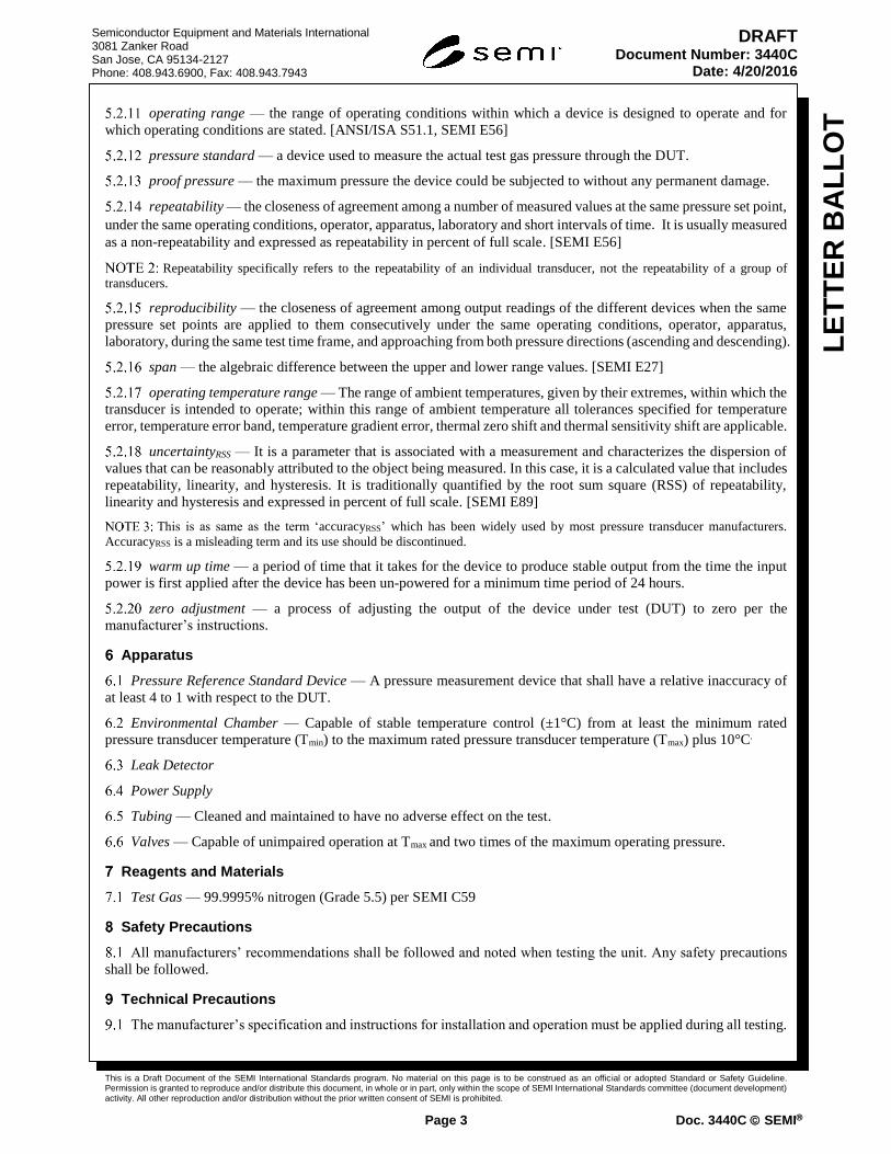
operating range — the range of operating conditions within which a device is designed to operate and for
which operating conditions are stated. [ANSI/ISA S51.1, SEMI E56]
pressure standard — a device used to measure the actual test gas pressure through the DUT.
proof pressure — the maximum pressure the device could be subjected to without any permanent damage.
repeatability — the closeness of agreement among a number of measured values at the same pressure set point,
under the same operating conditions, operator, apparatus, laboratory and short intervals of time. It is usually measured
as a non-repeatability and expressed as repeatability in percent of full scale. [SEMI E56]
Repeatability specifically refers to the repeatability of an individual transducer, not the repeatability of a group of
transducers.
reproducibility — the closeness of agreement among output readings of the different devices when the same
pressure set points are applied to them consecutively under the same operating conditions, operator, apparatus,
laboratory, during the same test time frame, and approaching from both pressure directions (ascending and descending).
span — the algebraic difference between the upper and lower range values. [SEMI E27]
operating temperature range — The range of ambient temperatures, given by their extremes, within which the
transducer is intended to operate; within this range of ambient temperature all tolerances specified for temperature
error, temperature error band, temperature gradient error, thermal zero shift and thermal sensitivity shift are applicable.
uncertaintyRSS — It is a parameter that is associated with a measurement and characterizes the dispersion of
values that can be reasonably attributed to the object being measured. In this case, it is a calculated value that includes
repeatability, linearity, and hysteresis. It is traditionally quantified by the root sum square (RSS) of repeatability,
linearity and hysteresis and expressed in percent of full scale. [SEMI E89]
This is as same as the term ‘accuracyRSS’ which has been widely used by most pressure transducer manufacturers.
AccuracyRSS is a misleading term and its use should be discontinued.
warm up time — a period of time that it takes for the device to produce stable output from the time the input
power is first applied after the device has been un-powered for a minimum time period of 24 hours.
zero adjustment — a process of adjusting the output of the device under test (DUT) to zero per the
manufacturer’s instructions.
Apparatus
Pressure Reference Standard Device — A pressure measurement device that shall have a relative inaccuracy of
at least 4 to 1 with respect to the DUT.
Environmental Chamber — Capable of stable temperature control (±1°C) from at least the minimum rated
pressure transducer temperature (Tmin) to the maximum rated pressure transducer temperature (Tmax) plus 10°C.
Leak Detector
Power Supply
Tubing — Cleaned and maintained to have no adverse effect on the test.
Valves — Capable of unimpaired operation at Tmax and two times of the maximum operating pressure.
Reagents and Materials
Test Gas — 99.9995% nitrogen (Grade 5.5) per SEMI C59
Safety Precautions
All manufacturers’ recommendations shall be followed and noted when testing the unit. Any safety precautions
shall be followed.
Technical Precautions
The manufacturer’s specification and instructions for installation and operation must be applied during all testing.

This is a Draft Document of the SEMI International Standards program. No material on this page is to be construed as an official or adopted Standard or Safety Guideline. Permission is granted to reproduce and/or distribute this document, in whole or in part, only within the scope of SEMI International Standards committee (document development) activity. All other reproduction and/or distribution without the prior written consent of SEMI is prohibited.
Page 4 Doc. 3440C SEMI
Semiconductor Equipment and Materials International 3081 Zanker Road San Jose, CA 95134-2127 Phone: 408.943.6900, Fax: 408.943.7943
LE
TT
ER
BA
LL
OT
DRAFT Document Number: 3440C
Date: 4/20/2016
The mounting position of the device must be in accordance with the manufacturer’s specifications. No external
mechanical constraints beyond the manufacturer’s recommended mounting position shall be used.
Calibration and Standardization
The pressure standard used is to be traceable to a recognized national standards lab, such as the US National
Institute of Standards and Technology (NIST).
All measurement devices shall be calibrated and maintained to the manufacturer’s recommendations. Current
calibration records shall be maintained.
Sampling
Randomly selected devices shall be sampled in accordance with SEMI E49.
Summary of Test Method
Leak Integrity — This test measures the allowable leak rate from any of the wetted surface area, into the
surrounding atmosphere, and is measured as a rate of helium in units of standard Pa·m3/s (atm·cc/s). The device shall
be measured following each test for performance and endurance.
Warm Up Time — Warm up time is the period that a device takes from its initial power-on or after the device
has been turned off for an extended time to read accurately.
Input Voltage Sensitivity — The voltage shall be varied across the specified range of voltages for the DUT while
all other major parameters remain constant.
Inaccuracy — This test shall determine the deviation between a measured value and the expected value of a
device. The maximum deviation among all the setpoints will be recorded as the inaccuracy of the device.
Hysteresis — Hysteresis shall be obtained by subtracting the ascending signal value from corresponding
descending signal value. The highest value among all the tested setpoints will be reported as the hysteresis of the
device.
Linearity — The linearity of the device shall be determined to be the maximum difference between the
observed value and the best-fit straight line (BFSL).
Repeatability — This test determines the repeatability of an individual device at identical pressures in a number
of consecutive cycles. The device will be pressurized at least three consecutive cycles in both of ascending and
descending directions.
Reproducibility — This test shall determine the reproducibility of different devices for the identical pressures.
A minimum of four devices shall be tested at the same time.
Thermal Coefficient — This test shall measure the output changes of the device in response to changes in ambient
temperature.
Accelerated Life Cycle — The device shall be capable of withstanding repeated full scale cycling. The device
shall meet its accuracy and leak integrity specifications during and at the end of the life cycle process.
Proof Pressure — Proof pressure test will determine maximum pressure that can be applied to a device under
test while ensuring that the performance of the device is not permanently affected.
Test Procedure
Preparation
Record ambient temperature, pressure units and gas type used for the test.
Record the manufacturer, model number and serial number of the DUT.
Record the full scale range and voltage or current output range of the DUT.
Leak Integrity
Test in accordance with SEMI F1.
This is a Draft Document of the SEMI International Standards program. No material on this page is to be construed as an official or adopted Standard or Safety Guideline. Permission is granted to reproduce and/or distribute this document, in whole or in part, only within the scope of SEMI International Standards committee (document development) activity. All other reproduction and/or distribution without the prior written consent of SEMI is prohibited.
Page 5 Doc. 3440C SEMI
Semiconductor Equipment and Materials International 3081 Zanker Road San Jose, CA 95134-2127 Phone: 408.943.6900, Fax: 408.943.7943
LE
TT
ER
BA
LL
OT
DRAFT Document Number: 3440C
Date: 4/20/2016
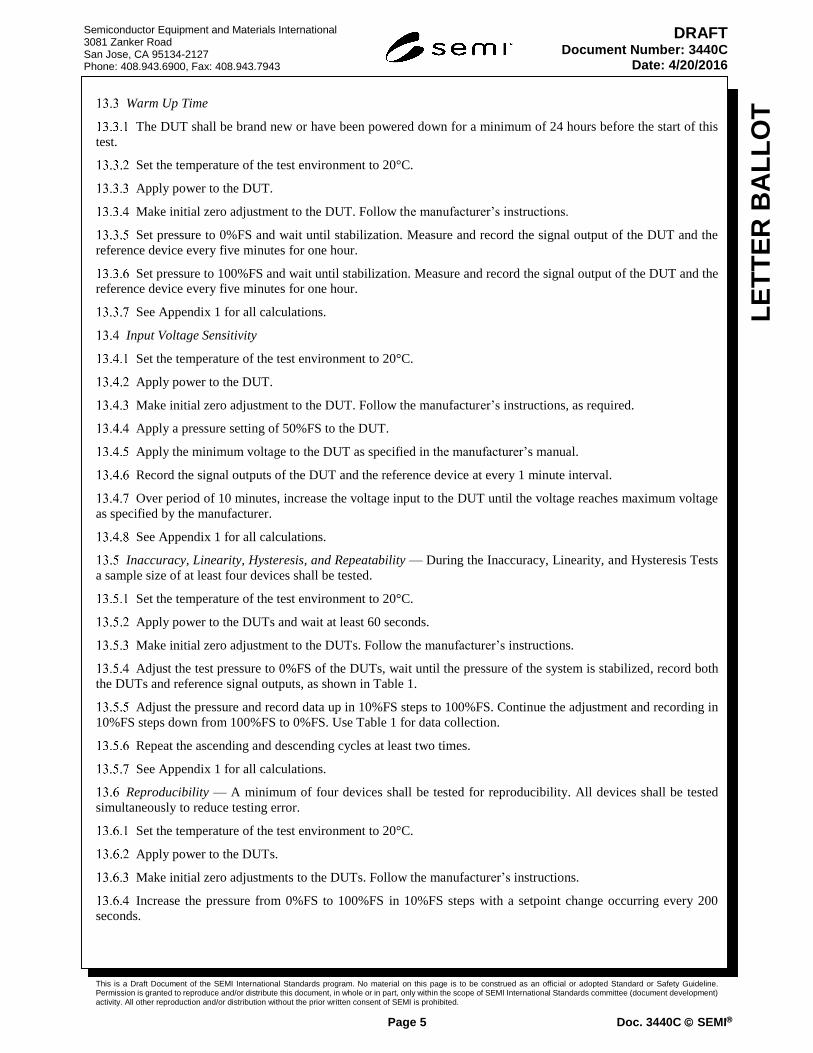
Warm Up Time
The DUT shall be brand new or have been powered down for a minimum of 24 hours before the start of this
test.
Set the temperature of the test environment to 20°C.
Apply power to the DUT.
Make initial zero adjustment to the DUT. Follow the manufacturer’s instructions.
Set pressure to 0%FS and wait until stabilization. Measure and record the signal output of the DUT and the
reference device every five minutes for one hour.
Set pressure to 100%FS and wait until stabilization. Measure and record the signal output of the DUT and the
reference device every five minutes for one hour.
See Appendix 1 for all calculations.
Input Voltage Sensitivity
Set the temperature of the test environment to 20°C.
Apply power to the DUT.
Make initial zero adjustment to the DUT. Follow the manufacturer’s instructions, as required.
Apply a pressure setting of 50%FS to the DUT.
Apply the minimum voltage to the DUT as specified in the manufacturer’s manual.
Record the signal outputs of the DUT and the reference device at every 1 minute interval.
Over period of 10 minutes, increase the voltage input to the DUT until the voltage reaches maximum voltage
as specified by the manufacturer.
See Appendix 1 for all calculations.
Inaccuracy, Linearity, Hysteresis, and Repeatability — During the Inaccuracy, Linearity, and Hysteresis Tests
a sample size of at least four devices shall be tested.
Set the temperature of the test environment to 20°C.
Apply power to the DUTs and wait at least 60 seconds.
Make initial zero adjustment to the DUTs. Follow the manufacturer’s instructions.
Adjust the test pressure to 0%FS of the DUTs, wait until the pressure of the system is stabilized, record both
the DUTs and reference signal outputs, as shown in Table 1.
Adjust the pressure and record data up in 10%FS steps to 100%FS. Continue the adjustment and recording in
10%FS steps down from 100%FS to 0%FS. Use Table 1 for data collection.
Repeat the ascending and descending cycles at least two times.
See Appendix 1 for all calculations.
Reproducibility — A minimum of four devices shall be tested for reproducibility. All devices shall be tested
simultaneously to reduce testing error.
Set the temperature of the test environment to 20°C.
Apply power to the DUTs.
Make initial zero adjustments to the DUTs. Follow the manufacturer’s instructions.
Increase the pressure from 0%FS to 100%FS in 10%FS steps with a setpoint change occurring every 200
seconds.

This is a Draft Document of the SEMI International Standards program. No material on this page is to be construed as an official or adopted Standard or Safety Guideline. Permission is granted to reproduce and/or distribute this document, in whole or in part, only within the scope of SEMI International Standards committee (document development) activity. All other reproduction and/or distribution without the prior written consent of SEMI is prohibited.
Page 6 Doc. 3440C SEMI
Semiconductor Equipment and Materials International 3081 Zanker Road San Jose, CA 95134-2127 Phone: 408.943.6900, Fax: 408.943.7943
LE
TT
ER
BA
LL
OT
DRAFT Document Number: 3440C
Date: 4/20/2016
Decrease the pressure from 100%FS to 0%FS in 10%FS steps with a setpoint change occurring every 200
seconds.
Record the pressure outputs from the DUTs and the reference at each setpoint for both ascending and
descending pressure directions.
See Appendix 1 for all calculations.
Table 1 Data Tabulation for Inaccuracy, Linearity, Repeatability and Hysteresis
Cycle No:
Pressure
Setpoint
(%FS)
Signal
Output of
DUT 1
Signal
Output of
DUT 2
Signal
Output of
DUT 3
Signal
Output of
DUT 4
Reference Output
0%
10%
20%
30%
40%
50%
60%
70%
80%
90%
100%
90%
80%
70%
60%
50%
40%
30%
20%
10%
0%
#1 Most commonly, the output values of DUTs are voltage or current values. The output of the reference can be
either voltage/current or pressure values depending on the type of the reference device used. The output of DUTs
and reference shall be consistent for calculation.
Thermal Coefficient
Apply power to the DUT.
Make initial zero adjustment to the DUT. Follow the manufacturer’s instructions.
The reference device should be outside of the temperature controlled environment.
Set the temperature (Te) of the temperature controlled environment to Tmin.
Allow the temperature to stabilize for two hours.
Set the DUT pressure setpoints to 0%FS, 25%FS, 50%FS, 75%FS and 100%FS.

This is a Draft Document of the SEMI International Standards program. No material on this page is to be construed as an official or adopted Standard or Safety Guideline. Permission is granted to reproduce and/or distribute this document, in whole or in part, only within the scope of SEMI International Standards committee (document development) activity. All other reproduction and/or distribution without the prior written consent of SEMI is prohibited.
Page 7 Doc. 3440C SEMI
Semiconductor Equipment and Materials International 3081 Zanker Road San Jose, CA 95134-2127 Phone: 408.943.6900, Fax: 408.943.7943
LE
TT
ER
BA
LL
OT
DRAFT Document Number: 3440C
Date: 4/20/2016
At each setpoint, record the signal output of the DUT and the reference device after stabilization. Record a
minimum of 10 values at each setpoint and calculate the average of the 10 values as shown in Table 2.
Repeat steps 13.7.5 to 13.7.6 for each Te shown in Table 3.
See Appendix 1 for all calculations.
Table 2 Data Tabulation for Thermal Coefficient
Te1 Te2 Te3 Te4 Te5 Te6 Te7 Te8 Te9
DU
T
Ref
.
DU
T
Ref
.
DU
T
Ref
.
DU
T
Ref
.
DU
T
Ref
.
DU
T
Ref
.
DU
T
Ref
.
DU
T
Ref
.
DU
T
Ref
.
Avg. of
10
readings
at 0%FS
Avg. of
10
readings
at
25%FS
Avg. of
10
readings
at
50%FS
Avg. of
10
readings
at
75%FS
Avg. of
10
readings
at
100%FS
Avg. of
10
readings
at 0%FS
This is a Draft Document of the SEMI International Standards program. No material on this page is to be construed as an official or adopted Standard or Safety Guideline. Permission is granted to reproduce and/or distribute this document, in whole or in part, only within the scope of SEMI International Standards committee (document development) activity. All other reproduction and/or distribution without the prior written consent of SEMI is prohibited.
Page 8 Doc. 3440C SEMI
Semiconductor Equipment and Materials International 3081 Zanker Road San Jose, CA 95134-2127 Phone: 408.943.6900, Fax: 408.943.7943
LE
TT
ER
BA
LL
OT
DRAFT Document Number: 3440C
Date: 4/20/2016
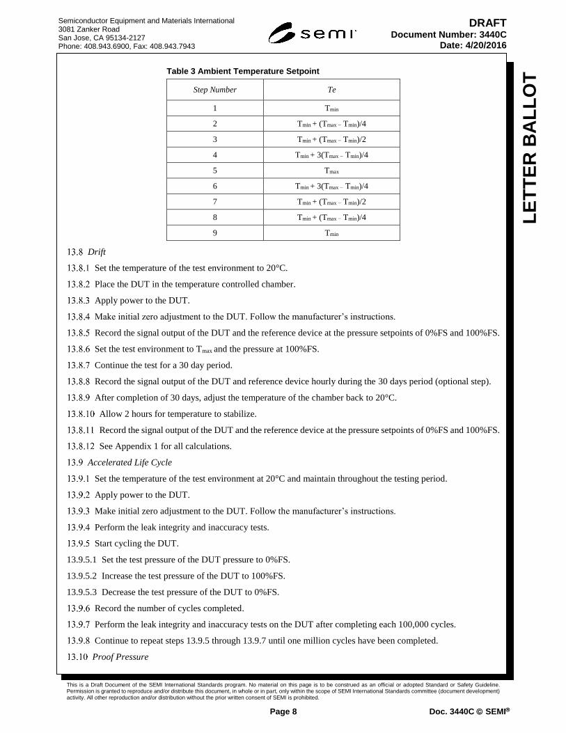
Table 3 Ambient Temperature Setpoint
Step Number Te
1 Tmin
2 Tmin + (Tmax − Tmin)/4
3 Tmin + (Tmax − Tmin)/2
4 Tmin + 3(Tmax − Tmin)/4
5 Tmax
6 Tmin + 3(Tmax − Tmin)/4
7 Tmin + (Tmax − Tmin)/2
8 Tmin + (Tmax − Tmin)/4
9 Tmin
Drift
Set the temperature of the test environment to 20°C.
Place the DUT in the temperature controlled chamber.
Apply power to the DUT.
Make initial zero adjustment to the DUT. Follow the manufacturer’s instructions.
Record the signal output of the DUT and the reference device at the pressure setpoints of 0%FS and 100%FS.
Set the test environment to Tmax and the pressure at 100%FS.
Continue the test for a 30 day period.
Record the signal output of the DUT and reference device hourly during the 30 days period (optional step).
After completion of 30 days, adjust the temperature of the chamber back to 20°C.
Allow 2 hours for temperature to stabilize.
Record the signal output of the DUT and the reference device at the pressure setpoints of 0%FS and 100%FS.
See Appendix 1 for all calculations.
Accelerated Life Cycle
Set the temperature of the test environment at 20°C and maintain throughout the testing period.
Apply power to the DUT.
Make initial zero adjustment to the DUT. Follow the manufacturer’s instructions.
Perform the leak integrity and inaccuracy tests.
Start cycling the DUT.
13.9.5.1 Set the test pressure of the DUT pressure to 0%FS.
13.9.5.2 Increase the test pressure of the DUT to 100%FS.
13.9.5.3 Decrease the test pressure of the DUT to 0%FS.
Record the number of cycles completed.
Perform the leak integrity and inaccuracy tests on the DUT after completing each 100,000 cycles.
Continue to repeat steps 13.9.5 through 13.9.7 until one million cycles have been completed.
Proof Pressure

This is a Draft Document of the SEMI International Standards program. No material on this page is to be construed as an official or adopted Standard or Safety Guideline. Permission is granted to reproduce and/or distribute this document, in whole or in part, only within the scope of SEMI International Standards committee (document development) activity. All other reproduction and/or distribution without the prior written consent of SEMI is prohibited.
Page 9 Doc. 3440C SEMI
Semiconductor Equipment and Materials International 3081 Zanker Road San Jose, CA 95134-2127 Phone: 408.943.6900, Fax: 408.943.7943
LE
TT
ER
BA
LL
OT
DRAFT Document Number: 3440C
Date: 4/20/2016
Set the temperature of the test environment at 20°C and maintain throughout the testing period.
Apply power to the DUT.
Make initial zero adjustment to the DUT. Follow the manufacturer’s instructions.
Perform the leak integrity and inaccuracy tests.
Set the pressure to 2 times the vendor’s maximum operating pressure for a period of 60 minutes.
Reduce the pressure to 0% FS.
Perform zero adjustment to the DUT if needed.
Perform the leak integrity test and inaccuracy tests.
Compare the leak integrity and inaccuracy test results with the DUT’s specification.
If the DUT meets its leak integrity and inaccuracy specifications, repeat 13.10.6 to 13.10.9 with the test
pressure increased 0.5 times the specified maximum operating pressure.
Reporting Results
The warm up time error is to be reported as shown in Table 4.
The input voltage sensitivity is to be reported as shown in Table 5.
The inaccuracy, linearity, repeatability, hysteresis and reproducibility are to be reported as shown in Table 6.
The BFSL method shall be clearly stated when reporting linearity.
The thermal coefficient at zero and span is to be reported as shown in Table 7.
The zero and span drift is to be reported as shown in Table 8.
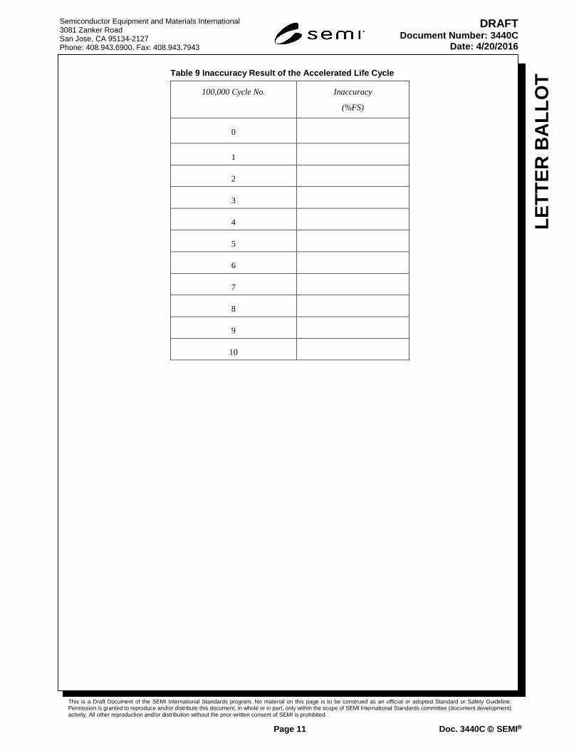
The inaccuracy during the accelerated life cycle is to be displayed as shown in Table 9.
Table 4 Warm Up Time Error
Time
(min)
Error at 0%FS
(%FS)
Error at 100%FS
(%FS)
0
5
10
15
20
25
30
35
40
45
50
55
60

This is a Draft Document of the SEMI International Standards program. No material on this page is to be construed as an official or adopted Standard or Safety Guideline. Permission is granted to reproduce and/or distribute this document, in whole or in part, only within the scope of SEMI International Standards committee (document development) activity. All other reproduction and/or distribution without the prior written consent of SEMI is prohibited.
Page 10 Doc. 3440C SEMI
Semiconductor Equipment and Materials International 3081 Zanker Road San Jose, CA 95134-2127 Phone: 408.943.6900, Fax: 408.943.7943
LE
TT
ER
BA
LL
OT
DRAFT Document Number: 3440C
Date: 4/20/2016
Table 5 Input Voltage Sensitivity Error
Power Supply
(V)
Error at 50%FS
(%FS)
Vmin
Vmin + (Vmax − Vmin)/10
Vmin + (Vmax − Vmin)/5
Vmin + 3(Vmax − Vmin)/10
Vmin + 2(Vmax − Vmin)/5
Vmin + (Vmax − Vmin)/2
Vmin + 3(Vmax − Vmin)/5
Vmin + 7(Vmax −Vmin)/10
Vmin + 4(Vmax − Vmin)/5
Vmin + 9(Vmax −Vmin)/10
Vmax
Table 6 Inaccuracy, Linearity, Repeatability, Hysteresis and Reproducibility Result
Result
Inaccuracy (%FS)
Linearity (BFSL) (%FS)
Repeatability (%FS)
Hysteresis (%FS)
Reproducibility (%FS)
Table 7 Thermal Coefficient at Zero and Span
TCzero
(%FS/°C)
TCspan
(%FS/°C)
Table 8 Zero and Span Drift
Zero Drift
(%FS)
Span Drift
(%FS)
This is a Draft Document of the SEMI International Standards program. No material on this page is to be construed as an official or adopted Standard or Safety Guideline. Permission is granted to reproduce and/or distribute this document, in whole or in part, only within the scope of SEMI International Standards committee (document development) activity. All other reproduction and/or distribution without the prior written consent of SEMI is prohibited.
Page 11 Doc. 3440C SEMI
Semiconductor Equipment and Materials International 3081 Zanker Road San Jose, CA 95134-2127 Phone: 408.943.6900, Fax: 408.943.7943
LE
TT
ER
BA
LL
OT
DRAFT Document Number: 3440C
Date: 4/20/2016
Table 9 Inaccuracy Result of the Accelerated Life Cycle
100,000 Cycle No. Inaccuracy
(%FS)
0
1
2
3
4
5
6
7
8
9
10
This is a Draft Document of the SEMI International Standards program. No material on this page is to be construed as an official or adopted Standard or Safety Guideline. Permission is granted to reproduce and/or distribute this document, in whole or in part, only within the scope of SEMI International Standards committee (document development) activity. All other reproduction and/or distribution without the prior written consent of SEMI is prohibited.
Page 12 Doc. 3440C SEMI
Semiconductor Equipment and Materials International 3081 Zanker Road San Jose, CA 95134-2127 Phone: 408.943.6900, Fax: 408.943.7943
LE
TT
ER
BA
LL
OT
DRAFT Document Number: 3440C
Date: 4/20/2016
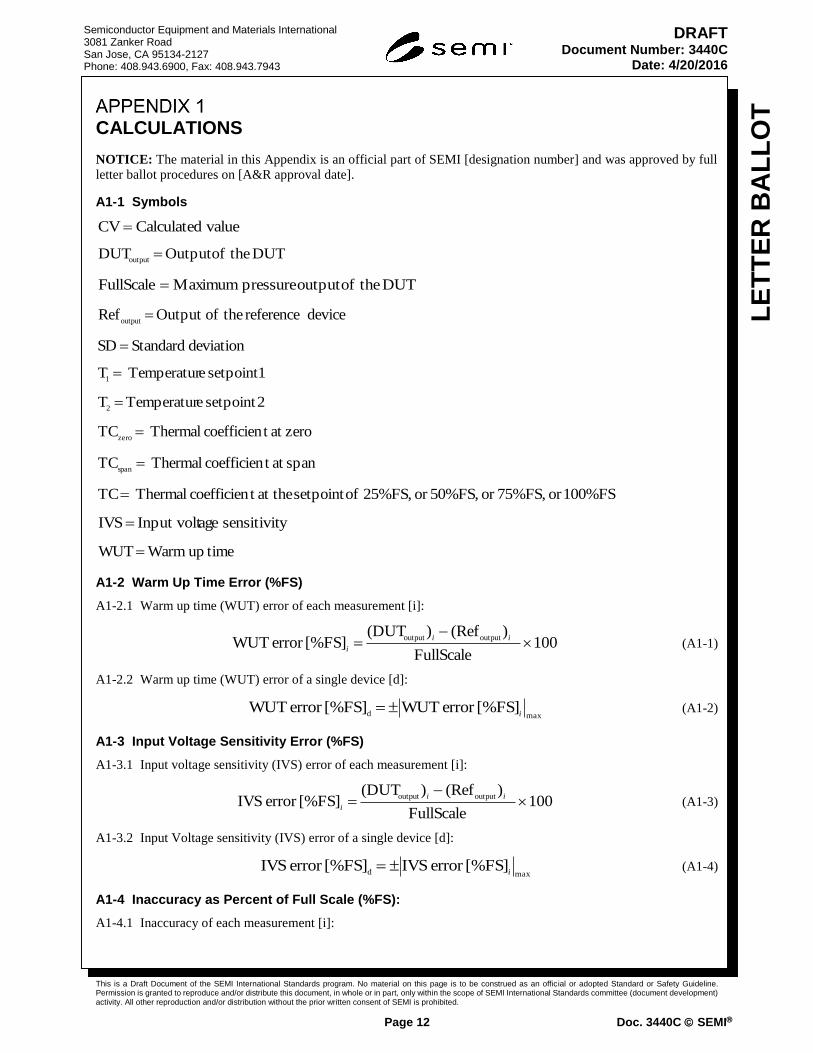
CALCULATIONS
NOTICE: The material in this Appendix is an official part of SEMI [designation number] and was approved by full
letter ballot procedures on [A&R approval date].
A1-1 Symbols
valueCalculated CV
DUT theofOutput DUToutput
DUT theofoutput pressure Maximum FullScale
device reference theofOutput Refoutput
deviation Standard SD
1setpoint eTemperatur T1
2setpoint eTemperatur T2
zeroat t coefficien Thermal TCzero
span at t coefficien Thermal TCspan
100%FSor 75%FS,or 50%FS,or 25%FS, ofsetpoint at thet coefficien Thermal TC
y sensitivit ageInput volt IVS
timeup Warm WUT
A1-2 Warm Up Time Error (%FS)
A1-2.1 Warm up time (WUT) error of each measurement [i]:
100FullScale
)(Ref )(DUT [%FS]error WUT
outputoutput
ii
i (A1-1)
A1-2.2 Warm up time (WUT) error of a single device [d]:
maxd
]%FS[error WUT [%FS]error WUTi
(A1-2)
A1-3 Input Voltage Sensitivity Error (%FS)
A1-3.1 Input voltage sensitivity (IVS) error of each measurement [i]:
100FullScale
)(Ref )(DUT [%FS]error IVS
outputoutput
ii
i (A1-3)
A1-3.2 Input Voltage sensitivity (IVS) error of a single device [d]:
maxd
]%FS[error IVS [%FS]error IVSi
(A1-4)
A1-4 Inaccuracy as Percent of Full Scale (%FS):
A1-4.1 Inaccuracy of each measurement [i]:
This is a Draft Document of the SEMI International Standards program. No material on this page is to be construed as an official or adopted Standard or Safety Guideline. Permission is granted to reproduce and/or distribute this document, in whole or in part, only within the scope of SEMI International Standards committee (document development) activity. All other reproduction and/or distribution without the prior written consent of SEMI is prohibited.
Page 13 Doc. 3440C SEMI
Semiconductor Equipment and Materials International 3081 Zanker Road San Jose, CA 95134-2127 Phone: 408.943.6900, Fax: 408.943.7943
LE
TT
ER
BA
LL
OT
DRAFT Document Number: 3440C
Date: 4/20/2016
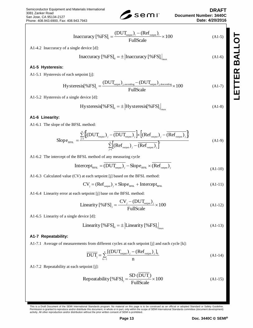
100FullScale
)(Ref )(DUT [%FS] Inaccuracy
outputoutput
ii
i (A1-5)
A1-4.2 Inaccuracy of a single device [d]:
maxid
[%FS] Inaccuracy [%FS] Inaccuracy (A1-6)
A1-5 Hysteresis:
A1-5.1 Hysteresis of each setpoint [j]:
100FullScale
)(DUT)DUT(]%FS[ Hysteresis
descending j,outputascending j,output
j (A1-7)
A1-5.2 Hysteresis of a single device [d]:
maxjd
[%FS] Hysteresis [%FS] Hysteresis (A1-8)
A1-6 Linearity:
A1-6.1 The slope of the BFSL method:
n
jjj
n
jjjjj
1
2
outputoutput
1outputoutputoutputoutput
BFSL
)(Ref)(Ref
)Ref()Ref()DUT()(DUT Slope (A1-9)
A1-6.2 The intercept of the BFSL method of any measuring cycle
jj)Ref(Slope)DUT(Intercept
outputBFSLoutputBFSL
(A1-10)
A1-6.3 Calculated value (CV) at each setpoint [j] based on the BFSL method:
BFSLBFSLoutputj
InterceptSlope)Ref(CV j
(A1-11)
A1-6.4 Linearity error at each setpoint [j] base on the BFSL method:
100FullScale
)(DUT CV [%FS]Linearity
output
jj
j (A1-12)
A1-6.5 Linearity of a single device [d]:
maxjd
[%FS]Linearity [%FS]Linearity (A1-13)
A1-7 Repeatability:
A1-7.1 Average of measurements from different cycles at each setpoint [j] and each cycle [k]:
n
1 k
koutputoutput
jn
])Ref()[(DUT DUT
jj (A1-14)
A1-7.2 Repeatability at each setpoint [j]:
100FullScale
)DUT( SD [%FS]ity Repeatabil
j
j (A1-15)
This is a Draft Document of the SEMI International Standards program. No material on this page is to be construed as an official or adopted Standard or Safety Guideline. Permission is granted to reproduce and/or distribute this document, in whole or in part, only within the scope of SEMI International Standards committee (document development) activity. All other reproduction and/or distribution without the prior written consent of SEMI is prohibited.
Page 14 Doc. 3440C SEMI
Semiconductor Equipment and Materials International 3081 Zanker Road San Jose, CA 95134-2127 Phone: 408.943.6900, Fax: 408.943.7943
LE
TT
ER
BA
LL
OT
DRAFT Document Number: 3440C
Date: 4/20/2016
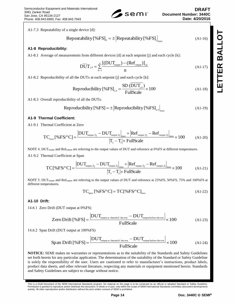
A1-7.3 Repeatability of a single device [d]:
maxjd
[%FS]ity Repeatabil [%FS]ity Repeatabil (A1-16)
A1-8 Reproducibility:
A1-8.1 Average of measurements from different devices [d] at each setpoint [j] and each cycle [k]:
n
1 d
kj,outputoutput,
____
n
)]Ref()[(DUT DUT kj (A1-17)
A1-8.2 Reproducibility of all the DUTs at each setpoint [j] and each cycle [k]:
100FullScale
)DUT( SD [%FS]ility Reproducib
k j,
k j, (A1-18)
A1-8.3 Overall reproducibility of all the DUTs:
maxk j,
[%FS]ility Reproducib [%FS]ility Reproducib (A1-19)
A1-9 Thermal Coefficient:
A1-9.1 Thermal Coefficient at Zero
100FullScaleTT
RefRefDUTDUT C][%FS/ TC
12
max1T output,2T output,max1T output,2T output,
zero
(A1-20)
DUToutput and Refoutput are referring to the output values of DUT and reference at 0%FS at different temperatures.
A1-9.2 Thermal Coefficient at Span
100FullScaleTT
RefRefDUTDUT C][%FS/ TC
12
max1T output,2T output,max1T output,2T output,
(A1-21)
DUToutput and Refoutput are referring to the output values of DUT and reference at 25%FS, 50%FS, 75% and 100%FS at
different temperatures.
maxspan
C][%FS/ TCC][%FS/ TC (A1-22)
A1-10 Drift:
Zero Drift (DUT output at 0%FS)
100FullScale
DUTDUT [%FS]Drift Zero
test thebeforeoutput test theof end at theoutput
(A1-23)
Span Drift (DUT output at 100%FS)
100FullScale
DUTDUT [%FS]Drift Span
test thebeforeoutput test theof end at theoutput
(A1-24)
NOTICE: SEMI makes no warranties or representations as to the suitability of the Standards and Safety Guidelines
set forth herein for any particular application. The determination of the suitability of the Standard or Safety Guideline
is solely the responsibility of the user. Users are cautioned to refer to manufacturer’s instructions, product labels,
product data sheets, and other relevant literature, respecting any materials or equipment mentioned herein. Standards
and Safety Guidelines are subject to change without notice.

This is a Draft Document of the SEMI International Standards program. No material on this page is to be construed as an official or adopted Standard or Safety Guideline. Permission is granted to reproduce and/or distribute this document, in whole or in part, only within the scope of SEMI International Standards committee (document development) activity. All other reproduction and/or distribution without the prior written consent of SEMI is prohibited.
Page 15 Doc. 3440C SEMI
Semiconductor Equipment and Materials International 3081 Zanker Road San Jose, CA 95134-2127 Phone: 408.943.6900, Fax: 408.943.7943
LE
TT
ER
BA
LL
OT
DRAFT Document Number: 3440C
Date: 4/20/2016
By publication of this Standard or Safety Guideline, SEMI takes no position respecting the validity of any patent rights
or copyrights asserted in connection with any items mentioned in this Standard or Safety Guideline. Users of this
Standard or Safety Guideline are expressly advised that determination of any such patent rights or copyrights and the
risk of infringement of such rights are entirely their own responsibility.