Embed Size (px)
Citation preview
www.streamnologies.com
800-828-SLTI
Background
ICPR began as a 1D hydrologic and
hydraulic (H&H) model more than 30
years ago with a focus on modeling
hydraulically interconnected and inter-
dependent pond systems. Hydrodynamic
channel and pipe flow were added in the
late 1980s. ICPR was the first proprietary
H&H model to be formally accepted by
FEMA nationally
(1995) for use on
Flood Insurance
Studies. In 2008, a
quasi-2D
groundwater
module was added
(PercPackTM) which
was our first foray
into integrated
surface water –
groundwater
modeling.
Our latest generation of ICPR, released in
2014, includes fully integrated 2D surface
water and groundwater flow with an
emphasis on interactions between surficial
aquifer systems and surface water bodies.
• Traditional 1D H&H
• 2D Overland Flow
• 2D Groundwater Flow
• Single Event Simulation
• Continuous Simulation
• Georeferenced Graphic System
• All Modules Fully Integrated
The combination of integrated surface
water – groundwater flow and continuous
simulation opens the door to many
complex water resources applications and
issues such as wetland hydro-period
assessments, wetland restoration, impacts
of sea level rise on groundwater tables,
consumptive water use, stormwater
reuse, water sustainability, irrigation
demands, and construction dewatering.
Flexible Mesh
The 2D computational framework for ICPR
is based on a flexible unstructured
triangular mesh. This approach allows the
mesh to shrink
where detail is
needed and to grow
in less critical areas.
The result can be
orders of magnitude
fewer computational
cells than a square
cell mesh without
loss of detail in
critical areas. And,
fewer cells mean
less computational
effort, faster run times, and smaller
output files.
The 1D H&H module of ICPR is fully
integrated with the 2D overland flow
module. Both 1D and 2D equations are
solved simultaneously eliminating
awkward numerical handoffs between
modules. Storm inlets and underground
pipe systems are easily incorporated into
the model.
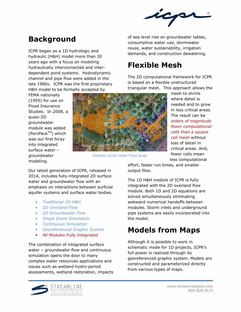
Models from Maps
Although it is possible to work in
schematic mode for 1D projects, ICPR’s
full power is realized through its
georeferenced graphic system. Models are
constructed and parameterized directly
from various types of maps.
Detailed 1D/2D Urban Flood Study
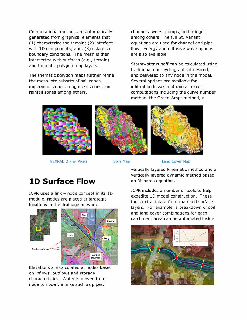
Computational meshes are automatically
generated from graphical elements that:
(1) characterize the terrain; (2) interface
with 1D components; and, (3) establish
boundary conditions. The mesh is then
intersected with surfaces (e.g., terrain)
and thematic polygon map layers.
The thematic polygon maps further refine
the mesh into subsets of soil zones,
impervious zones, roughness zones, and
rainfall zones among others.
1D Surface Flow
ICPR uses a link – node concept in its 1D
module. Nodes are placed at strategic
locations in the drainage network.
Elevations are calculated at nodes based
on inflows, outflows and storage
characteristics. Water is moved from
node to node via links such as pipes,
channels, weirs, pumps, and bridges
among others. The full St. Venant
equations are used for channel and pipe
flow. Energy and diffusive wave options
are also available.
Stormwater runoff can be calculated using
traditional unit hydrographs if desired,
and delivered to any node in the model.
Several options are available for
infiltration losses and rainfall excess
computations including the curve number
method, the Green-Ampt method, a
vertically layered kinematic method and a
vertically layered dynamic method based
on Richards equation.
ICPR includes a number of tools to help
expedite 1D model construction. These
tools extract data from map and surface
layers. For example, a breakdown of soil
and land cover combinations for each
catchment area can be automated inside
www.streamnologies.com
800-828-SLTI
ICPR. Channel cross sections can be
extracted from a ground surface DEM, as
well as storage characteristics for lakes,
detention ponds, and wetland
depressions.
Water surface profiles can be animated
along any user defined link path.
2D Overland Flow
Computational Methods
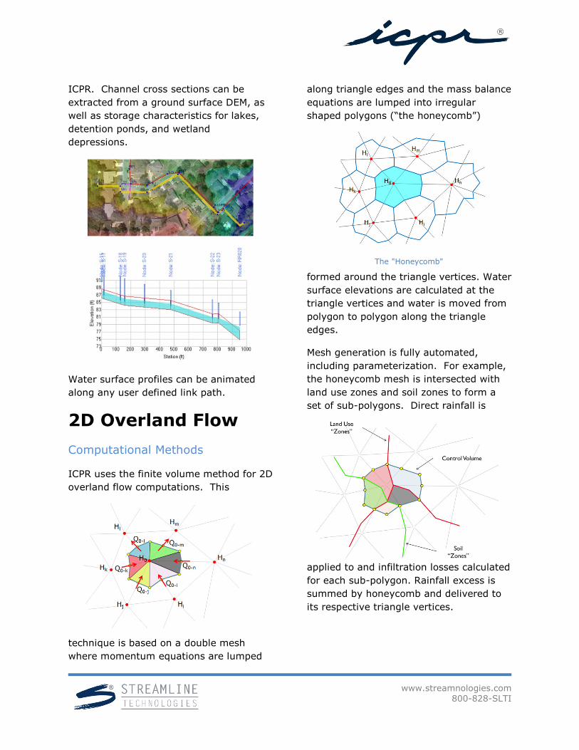
ICPR uses the finite volume method for 2D
overland flow computations. This
technique is based on a double mesh
where momentum equations are lumped
along triangle edges and the mass balance
equations are lumped into irregular
shaped polygons (“the honeycomb”)
formed around the triangle vertices. Water
surface elevations are calculated at the
triangle vertices and water is moved from
polygon to polygon along the triangle
edges.
Mesh generation is fully automated,
including parameterization. For example,
the honeycomb mesh is intersected with
land use zones and soil zones to form a
set of sub-polygons. Direct rainfall is
applied to and infiltration losses calculated
for each sub-polygon. Rainfall excess is
summed by honeycomb and delivered to
its respective triangle vertices.
The "Honeycomb"
The triangular mesh and corresponding
honeycomb are flexible and unstructured,
allowing the mesh to grow and shrink as
needed to capture critical areas in the
drainage system.
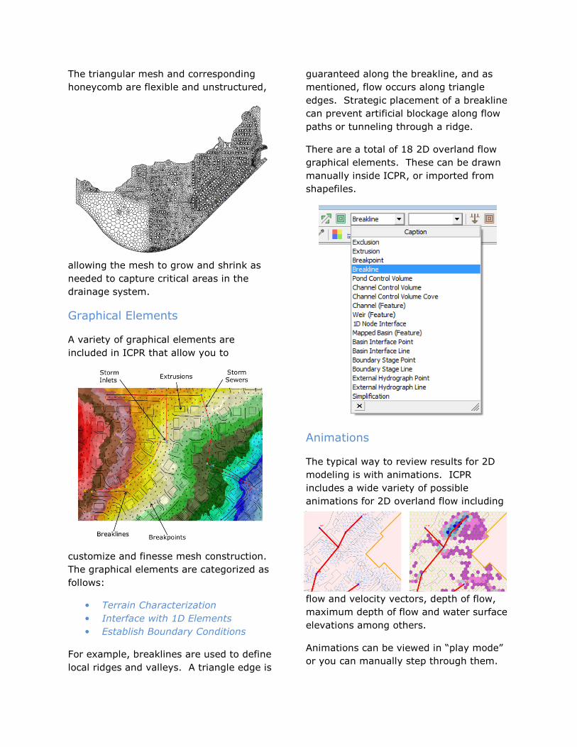
Graphical Elements
A variety of graphical elements are
included in ICPR that allow you to
customize and finesse mesh construction.
The graphical elements are categorized as
follows:
• Terrain Characterization
• Interface with 1D Elements
• Establish Boundary Conditions
For example, breaklines are used to define
local ridges and valleys. A triangle edge is
guaranteed along the breakline, and as
mentioned, flow occurs along triangle
edges. Strategic placement of a breakline
can prevent artificial blockage along flow
paths or tunneling through a ridge.
There are a total of 18 2D overland flow
graphical elements. These can be drawn
manually inside ICPR, or imported from
shapefiles.
Animations
The typical way to review results for 2D
modeling is with animations. ICPR
includes a wide variety of possible
animations for 2D overland flow including
flow and velocity vectors, depth of flow,
maximum depth of flow and water surface
elevations among others.
Animations can be viewed in “play mode”
or you can manually step through them.

www.streamnologies.com
800-828-SLTI
You can also go directly to a specific point
in time. Most animations can be paused
and then exported by simply right-clicking
on the animation view.
2D Groundwater
Computational Methods
The 2D groundwater module in ICPR is
based on the finite element method with a
6-point quadratic triangular element.
• Heads Calculated at Nodes
• Saturated Horizontal Flow
• Seepage at Ground Surface
• Leakage Through Confining Layer
The focus of the groundwater module is
the surficial aquifer and its interaction
with surface water bodies. It includes
seepage between the ground surface and
the surficial aquifer as well as vertical
leakage through a confining layer.
Seepage and leakage are bi-directional.
Spatiotemporal boundary conditions can
be applied below the confining layer.
Like the surface, a honeycomb is formed
around the vertices of the triangular
computational mesh. But unlike the
surface, the honeycomb is also formed
around mid-nodes.
The surface and groundwater honeycombs
are intersected with one another and with
soil zones, impervious zones and rainfall
zones. The result is a set of sub-
polygons, each having a surface ID, a
groundwater ID and soil, land cover and
rainfall station attributes.
Rainfall excess for any sub-polygon is
delivered to the corresponding surface
node and recharge is delivered to its
associated groundwater node.
Surface and groundwater meshes do not
have to be aligned.
Graphical Elements
Various groundwater graphical elements
are used to aid in mesh construction,
similar to
overland flow.
Irrigation
wells and
drains (tile
drain or
roadway
underdrain)
can be
included in
your project.
An exclusion graphic element can be used
to model a fully penetrating retaining wall.
Boundary conditions can be specified at a

point, along a line, or over an area
(polygon). Both stage and flow boundary
conditions are possible.
Results and Animations
Like overland flow, there is a wide variety
of reports and animations available for
analyzing the groundwater results.
Here is an example of a proposed
commercial site with 2 retention ponds
that rely on percolation for storage
recovery. There is a river south and east
of the site and groundwater flow is toward
the river. Fluctuating water levels in the
river automatically become known head
conditions for the groundwater model.
Groundwater elevations at hour 120 are
shown above. Cross section A–A’ depicts
ground elevations, the initial water table
and the water table at 120 hours, 4 days
after the rain stopped.
Aggregate seepage amounts between the
river and the adjacent water table are
shown below. The river rises faster and
higher than the adjacent water table.
Consequently, a portion of the river flow
seeps from and into the water table.
Later, as the river subsides, there is
seepage from the water table into the
river.
Section B–B’, through the two ponds,
indicates that they have not fully
recovered after 120 hours.
www.streamnologies.com
800-828-SLTI
Demonstration
Project
Levee Breach, Village of Wellington
Palm Beach County, Florida
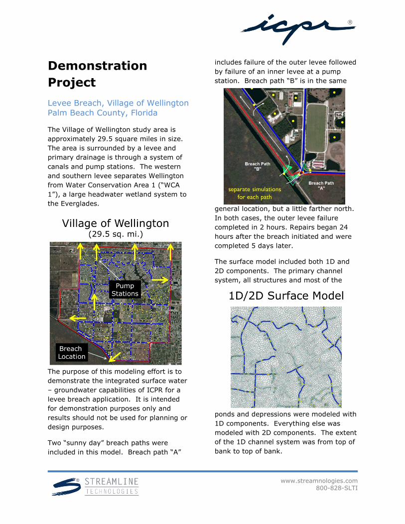
The Village of Wellington study area is
approximately 29.5 square miles in size.
The area is surrounded by a levee and
primary drainage is through a system of
canals and pump stations. The western
and southern levee separates Wellington
from Water Conservation Area 1 (“WCA
1”), a large headwater wetland system to
the Everglades.
The purpose of this modeling effort is to
demonstrate the integrated surface water
– groundwater capabilities of ICPR for a
levee breach application. It is intended
for demonstration purposes only and
results should not be used for planning or
design purposes.
Two “sunny day” breach paths were
included in this model. Breach path “A”
includes failure of the outer levee followed
by failure of an inner levee at a pump
station. Breach path “B” is in the same
general location, but a little farther north.
In both cases, the outer levee failure
completed in 2 hours. Repairs began 24
hours after the breach initiated and were
completed 5 days later.
The surface model included both 1D and
2D components. The primary channel
system, all structures and most of the
ponds and depressions were modeled with
1D components. Everything else was
modeled with 2D components. The extent
of the 1D channel system was from top of
bank to top of bank.
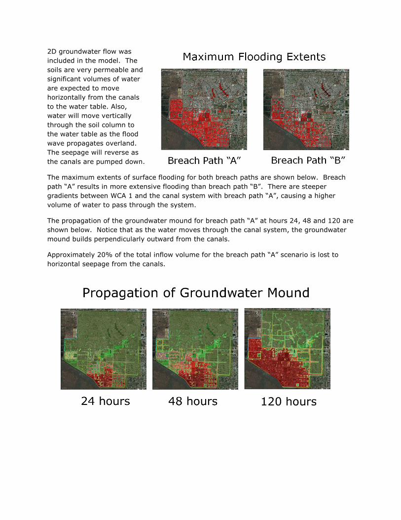
2D groundwater flow was
included in the model. The
soils are very permeable and
significant volumes of water
are expected to move
horizontally from the canals
to the water table. Also,
water will move vertically
through the soil column to
the water table as the flood
wave propagates overland.
The seepage will reverse as
the canals are pumped down.
The maximum extents of surface flooding for both breach paths are shown below. Breach
path “A” results in more extensive flooding than breach path “B”. There are steeper
gradients between WCA 1 and the canal system with breach path “A”, causing a higher
volume of water to pass through the system.
The propagation of the groundwater mound for breach path “A” at hours 24, 48 and 120 are
shown below. Notice that as the water moves through the canal system, the groundwater
mound builds perpendicularly outward from the canals.
Approximately 20% of the total inflow volume for the breach path “A” scenario is lost to
horizontal seepage from the canals.