Embed Size (px)
Citation preview
STRENGTH AND DURABILITY OF INTEGRAL ABUTMENT CONNECTION DETAILS FOR ABC – PHASE II
Quarterly Progress ReportFor the period ending March 31, 2018
Submitted by:PI- Travis Hosteng
Graduate Student- Austin DeJong
Affiliation: Department of Civil, Construction, and Environmental EngineeringIowa State University
Ames, IA
Submitted to:ABC-UTC
Florida International UniversityMiami, FL


1. Background and Introduction
Accelerated Bridge Construction (ABC) in recent years has become the construction procedure of use by many bridge engineering agencies around the world, and in the United States. ABC is being analyzed and formalized to replace conventional bridge construction due to the significant decrease in construction time and traffic impact, as well as the increase in quality control and worker/public safety. Some cases of ABC can replace an existing bridge in a matter of weeks, or even days, compared to conventional bridge construction which can have construction times of months and cause detours that greatly affect the flow of traffic, as well as the safety of the public and construction workers.
ABC differs from conventional bridge construction by utilizing prefabricated elements, sections, and entire structures which are then lifted, slid, and/or rotated into place and connected. These connections have been, and still are being, researched and tested for many connection locations within a bridge.
One connection still under research and testing is the integral abutment. An integral abutment is a connection composed of combined shear and moment connections between the bridge superstructure and substructure and eliminates the expansion joint at the ends of the bridge. Expansion joints are prone to damage and deterioration which subsequently facilitates infiltration of water, debris, and deicing chemicals into the bearing cavity resulting in corrosion and deterioration of girder ends and bearings. With this in mind, the so-called “jointless” bridge connection is being pursued by transportation agencies and their collaborative research programs.
Since the integral abutment is greatly reinforced to resist the different forces acting on both the substructure and superstructure, the issue of transporting and installing these elements govern the design. The issue of transporting comes from the weight of the specimen, and the installation issues are the result of the splices that will need to be connected after the lift, slide, etc., has been completed.
To alleviate these issues, the method of cast-in-place integral abutments has been the common procedure for this ABC connection. This procedure eases the tolerances of the connection during construction by creating a simpler integral connection, which is done by placing the prefabricated pile cap on the driven piles, setting the prefabricated girder, and then placing a closure pour over the connection to create the integral connectivity. A great downside to this connection detail is the closure pour is typically consisted of High-Performance Concrete (HPC), or Ultra-High-Performance Concrete (UHPC). Both materials are high in cost, and require high early strength during curing to allow the bridge to be reopened as soon as possible.
2. Problem Statement
The goal of this project is to design and analyze the strength and durability of integral abutment connection details, as well as documenting the constructability of the details. These connection details shall perform like the conventional cast-in-place construction of the integral abutment,

but shall be designed to facilitated rapid, prefabricated construction with both durability and constructability in mind. Also, the design of the connections shall be a revision of the two integral abutment connection details designed and tested in Phase I of the project, as well as any other new potential solutions.
3. Research Approach and MethodsThe overall approach of this project is to use the same procedure and methodology used for Phase I of the project. The approach to the design was to maintain the strength of the integral abutment, but be able to introduce ABC techniques to the connection details. These designs were then reviewed by a Technical Advisory Committee (TAC) and revised based on the discussions between the deign team and the TAC. With designs approved by the TAC, construction of full-scale specimens was initiated, and will be used for laboratory testing of the connection details.
The laboratory testing will consist of rigorous documentation of the constructability of the specimens, as well as applying two different loads via actuators to the specimens once the connections had been completed. The two loads will be a 100-kip horizontal load applied to the deck/girder interface to simulate thermal contraction of the bridge, and a 400-kip vertical load applied to the edge of the specimen deck to simulate thermal expansion and live loading of the bridge. (Figure 1)
4.
Description of Research Project TasksThe following is a description of tasks carried out to date.
Task 1 – Literature ReviewProposed task description:
Conduct a detailed review of the results from Phase I, as well as a literature review of ABC procedures and integral abutments.
Description of work performed up to this period:
Figure 1: Laboratory Test Setup for integral abutment specimens
2’-11” x 4’ x 8’ “Pile Cap”
Connection Joint
4’ x 4’ x 8’ “Integral
Diaphragm”
Reaction Blocks
9” x 3’ x 8’ “Deck”
W36 Beam
400-kip Vertical Load
100-kip Horizontal Load

Literature review conducted and reported into beginning of final report.
Task 2 – Connection Details Design Proposed task description:
Develop and design details for an integral abutment using ABC methods, as well as results of Phase I.
Description of work performed up to this period: Integral abutment connection details have been designed, reviewed by the TAC, and approved by the TAC and design team. UPDATE: designs are continuously reviewed/analyzed during construction phase to look for any deficiencies or areas of potential modification in the future and discussed with the TAC.
Task 3- Investigation of Connection Details Constructability Proposed task description:
Investigate and evaluate the constructability aspects of the connection details, and adjust design accordingly. Also, test the flowability of UHPC through the designed cross-section of the UHPC-Joint connection detail.
Description of work performed up to this period:The constructability of each connection detail has been reviewed by the TAC and design team and approved. UPDATE: constructability of each specimen as they are being constructed continuously reviewed/analyzed during construction phase to look for any deficiencies or areas of potential modification in the future and discussed with the TAC. Documentation is continuous such that this information can be presented in the final report.
Task 4- Construction and Laboratory Testing of Connection DetailsProposed task description:
Construct and test full scale specimens of the connection details in the laboratory, measuring performance of the details in terms of durability and strength. Also, compare laboratory test results to analysis done in Finite Element software, as well as analyze other scenarios.
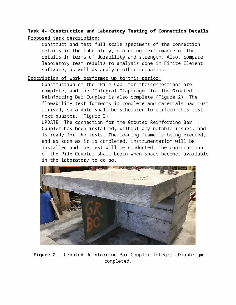
Description of work performed up to this period:Construction of the “Pile Cap” for the connections are complete, and the “Integral Diaphragm” for the Grouted Reinforcing Bar Coupler is also complete (Figure 2). The flowability test formwork is complete and materials had just arrived, so a date shall be scheduled to perform this test next quarter. (Figure 3) UPDATE: The connection for the Grouted Reinforcing Bar Coupler has been installed, without any notable issues, and is ready for the tests. The loading frame is being erected, and as soon as it is completed, instrumentation will be installed and the test will be conducted. The construction of the Pile Coupler shall begin when space becomes available in the laboratory to do so.

Figure 2. Grouted Reinforcing Bar Coupler Integral Diaphragm completed.
Figure 3. Flowability test formwork.
Task 5- Analysis of Testing Results and Final ReportProposed task description:
Present the results of this study in a final report discussing the findings of the research for future use of integral abutments in ABC applications.
Description of work performed up to this period:Parts of the final report are being composed as the project progresses.
5. Expected Results and Specific DeliverablesThe expected results of the laboratory testing are to be similar to the results found in Phase I testing of the connection details, specifically of the control cast-in-place specimen. Results will show joint cracking of the specimens due to the loadings, as well as development of connections through measurements of the development of reinforcing steel stresses. Another key result that will be shown is the constructability of each connection detail, which will be shown through a highly descriptive report of the construction of the specimens.
Deliverables for this project include:- Final report consisting of all the above background information, research and design
methodologies, construction and laboratory testing of specimens, and analysis of results- Formal design drawings of full scale specimens of connection details
6. ScheduleProgress of tasks in this project is shown in the table below.
7.R
eferences
Phase I Final Report:
Hosteng, T., Phares, B., & Redd, S. (2015). Strength, Durability, and Application of Grouted Couplers for Integral Abutments in Accelerated Bridge Construction. Ames: Iowa State University Bridge Engineering Center.