Embed Size (px)
Citation preview
Back to Basics: Signal Generation
1 Nov 2012
Back to Basics Training
Copyright Agilent
1
2
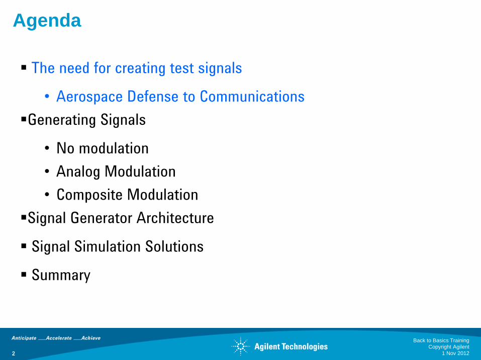
Agenda
The need for creating test signals
• Aerospace Defense to Communications
Generating Signals
• No modulation
• Analog Modulation
• Composite Modulation
Signal Generator Architecture
Signal Simulation Solutions
Summary
1 Nov 2012
Back to Basics Training
Copyright Agilent
2
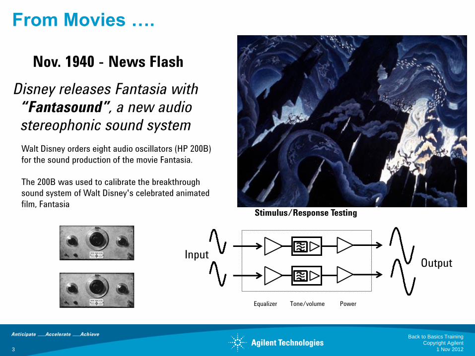
From Movies ….
Walt Disney orders eight audio oscillators (HP 200B)
for the sound production of the movie Fantasia.
The 200B was used to calibrate the breakthrough
sound system of Walt Disney's celebrated animated
film, Fantasia
Nov. 1940 - News Flash
Disney releases Fantasia with
“Fantasound”, a new audio
stereophonic sound system
Output Input
Power Tone/volume Equalizer
Stimulus/Response Testing
1 Nov 2012 3
Back to Basics Training
Copyright Agilent
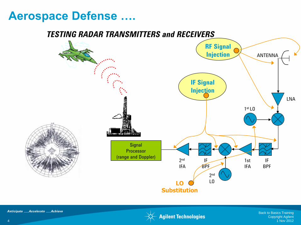
Aerospace Defense ….
LNA
IF
BPF
Signal
Processor
(range and Doppler) 1st
IFA
2nd
LO
IF
BPF
2nd
IFA
ANTENNA
RF Signal
Injection
IF Signal
Injection
LO Substitution
1st LO
TESTING RADAR TRANSMITTERS and RECEIVERS
1 Nov 2012
Back to Basics Training
Copyright Agilent
4
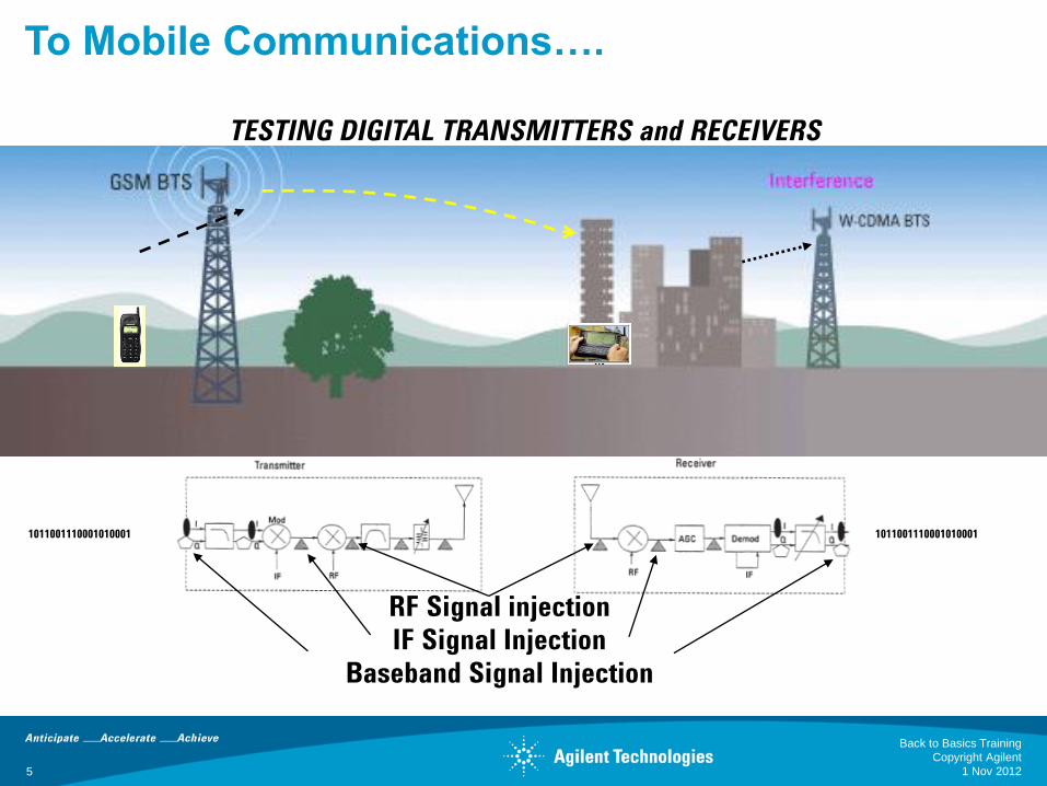
To Mobile Communications….
TESTING DIGITAL TRANSMITTERS and RECEIVERS
1011001110001010001 1011001110001010001
RF Signal injection
IF Signal Injection
Baseband Signal Injection
1 Nov 2012
Back to Basics Training
Copyright Agilent
5
6
Agenda
The need for creating test signals
• Aerospace Defense to Communications
Generating Signals
• No modulation
• Analog Modulation
• Composite Modulation
Signal Generator Architecture
Signal Simulation Solutions
Summary
1 Nov 2012
Back to Basics Training
Copyright Agilent

Generating Signals – No Modulation
Volt
age
Time
Volt
age
Frequency
The sine wave is the basic, non-modulated signal: It is useful for
stimulus/response testing of linear components and for Local Oscillator
substitution. Available frequencies range from low RF to Millimeter.
RF Microwave Millimeter
20-70 GHz 300 GHz 6 GHz
Spectrum Analyzer Oscilloscope
Continuous Wave (CW)
1 Nov 2012
Back to Basics Training
Copyright Agilent
7

Generating Signals – Analog Modulation
V(t) = A(t)*cos[2πfct + Φ(t)]
AM, Pulse FM, PM
Modulation: Where the Information Resides
1 Nov 2012
Back to Basics Training
Copyright Agilent
8
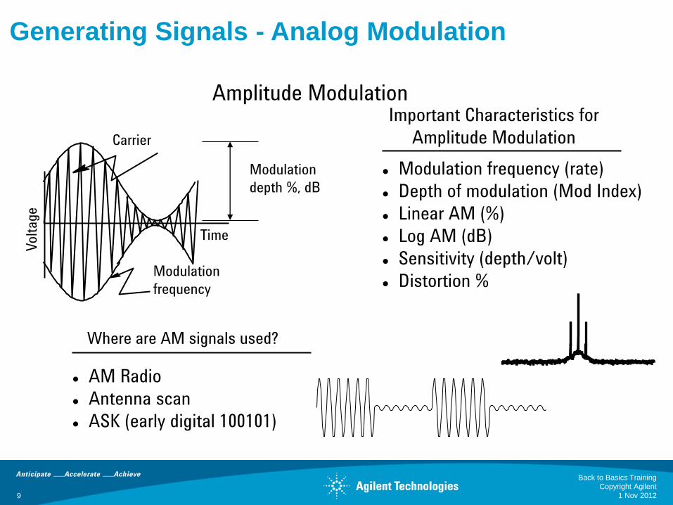
Generating Signals - Analog Modulation
Important Characteristics for
Amplitude Modulation
Volt
age
Time
Carrier
Modulation
frequency
Modulation frequency (rate)
Depth of modulation (Mod Index)
Linear AM (%)
Log AM (dB)
Sensitivity (depth/volt)
Distortion %
Modulation
depth %, dB
Amplitude Modulation
Where are AM signals used?
AM Radio
Antenna scan
ASK (early digital 100101)
1 Nov 2012
Back to Basics Training
Copyright Agilent
9
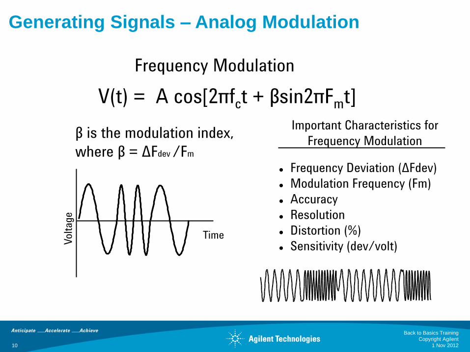
Generating Signals – Analog Modulation
Volt
age
Time
Important Characteristics for
Frequency Modulation
V(t) = A cos[2πfct + βsin2πFmt]
β is the modulation index,
where β = ΔFdev /Fm
Frequency Deviation (ΔFdev)
Modulation Frequency (Fm)
Accuracy
Resolution
Distortion (%)
Sensitivity (dev/volt)
Frequency Modulation
1 Nov 2012
Back to Basics Training
Copyright Agilent
10
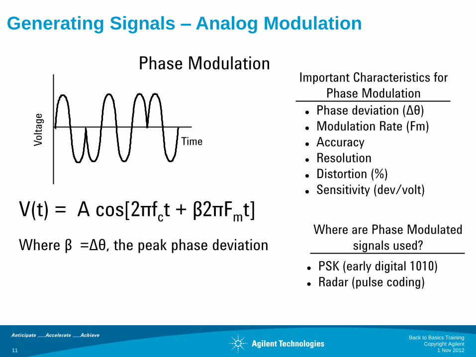
Generating Signals – Analog Modulation
Important Characteristics for
Phase Modulation
Phase deviation (Δθ)
Modulation Rate (Fm)
Accuracy
Resolution
Distortion (%)
Sensitivity (dev/volt)
Volt
age
Time
Phase Modulation
V(t) = A cos[2πfct + β2πFmt]
Where β =Δθ, the peak phase deviation Where are Phase Modulated
signals used?
PSK (early digital 1010)
Radar (pulse coding)
1 Nov 2012
Back to Basics Training
Copyright Agilent
11
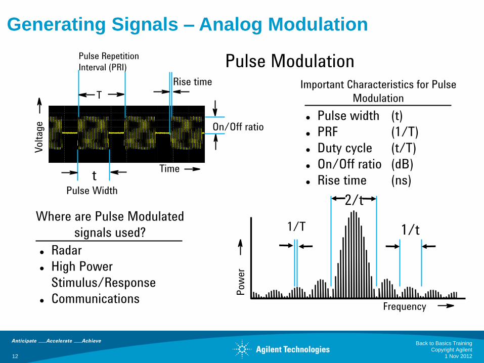
Generating Signals – Analog Modulation
Time
Pulse Width
On/Off ratio
Rise time
T
t
Pow
er
1/t 1/T
Volt
age
Important Characteristics for Pulse
Modulation
Pulse width (t)
PRF (1/T)
Duty cycle (t/T)
On/Off ratio (dB)
Rise time (ns)
Pulse Modulation
Where are Pulse Modulated
signals used?
Radar
High Power
Stimulus/Response
Communications
Pulse Repetition
Interval (PRI)
Frequency
2/t
1 Nov 2012
Back to Basics Training
Copyright Agilent
12
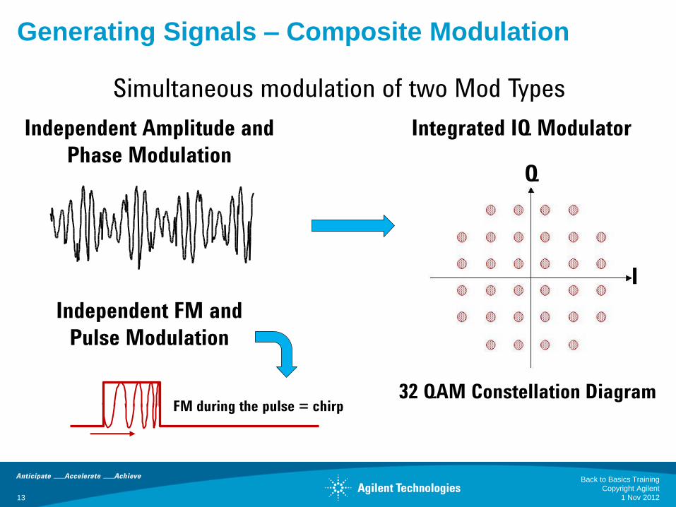
Generating Signals – Composite Modulation
Independent Amplitude and
Phase Modulation Q
32 QAM Constellation Diagram
I
Integrated IQ Modulator
Independent FM and
Pulse Modulation
FM during the pulse = chirp
Simultaneous modulation of two Mod Types
1 Nov 2012
Back to Basics Training
Copyright Agilent
13

Vector Signal Changes or Modifications
Phase
0 deg
Magnitude Change
Phase 0 deg
Phase Change
Frequency Change Both Change
0 deg
0 deg
Generating Signals – Composite Modulation
1 Nov 2012
Back to Basics Training
Copyright Agilent
14
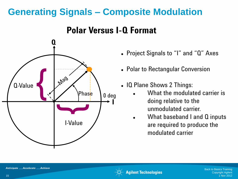
Polar Versus I-Q Format
Phase 0 deg
Project Signals to “I” and “Q” Axes
Polar to Rectangular Conversion
IQ Plane Shows 2 Things:
What the modulated carrier is
doing relative to the
unmodulated carrier.
What baseband I and Q inputs
are required to produce the
modulated carrier
{ {
Q-Value
I-Value
Generating Signals – Composite Modulation
Q
I
1 Nov 2012
Back to Basics Training
Copyright Agilent
15
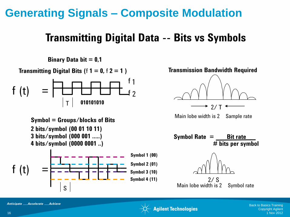
Generating Signals – Composite Modulation
f (t) = f 1
f 2
Transmitting Digital Bits (f 1 = 0, f 2 = 1 )
2/ S Main lobe width is 2
Symbol rate
Transmission Bandwidth Required
T
Binary Data bit = 0,1
010101010
Symbol = Groups/blocks of Bits
2 bits/symbol (00 01 10 11)
3 bits/symbol (000 001 …..)
4 bits/symbol (0000 0001 ..)
Symbol 1 (00)
Symbol 2 (01)
Symbol 3 (10)
Symbol 4 (11)
Main lobe width is 2
Sample rate
2/ T
S
Symbol Rate = Bit rate # bits per symbol
f (t) =
Transmitting Digital Data -- Bits vs Symbols
1 Nov 2012
Back to Basics Training
Copyright Agilent
16
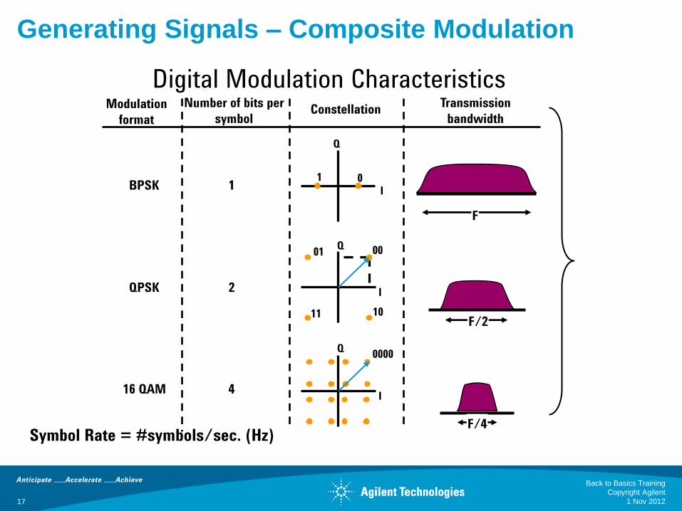
Generating Signals – Composite Modulation
Symbol Rate = #symbols/sec. (Hz)
BPSK 1
Number of bits per
symbol
Transmission
bandwidth Modulation
format
QPSK 2
16 QAM 4
F
F/2
F/4
I
Q
0 1
I
Q 00 01
10 11
I
Q 0000
Constellation
Digital Modulation Characteristics
1 Nov 2012
Back to Basics Training
Copyright Agilent
17
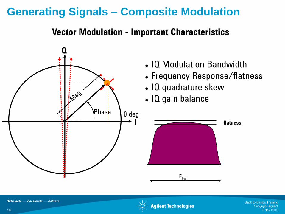
Vector Modulation - Important Characteristics
Phase 0 deg
IQ Modulation Bandwidth
Frequency Response/flatness
IQ quadrature skew
IQ gain balance
Generating Signals – Composite Modulation
Q
I
Fbw
flatness
1 Nov 2012
Back to Basics Training
Copyright Agilent
18
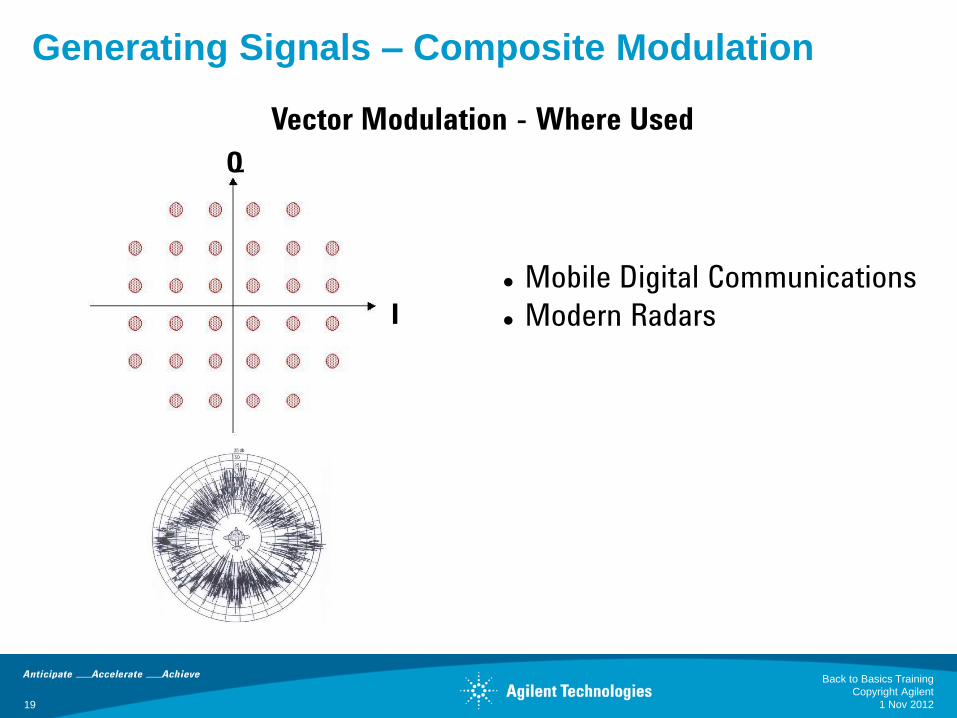
Vector Modulation - Where Used
Mobile Digital Communications
Modern Radars
Generating Signals – Composite Modulation
Q
I
1 Nov 2012
Back to Basics Training
Copyright Agilent
19
20
Agenda
The need for creating test signals
• Aerospace Defense to Communications
Generating Signals
• No modulation
• Analog Modulation
• Composite Modulation
Signal Generator Architecture
Signal Simulation Solutions
Summary
1 Nov 2012
Back to Basics Training
Copyright Agilent
21
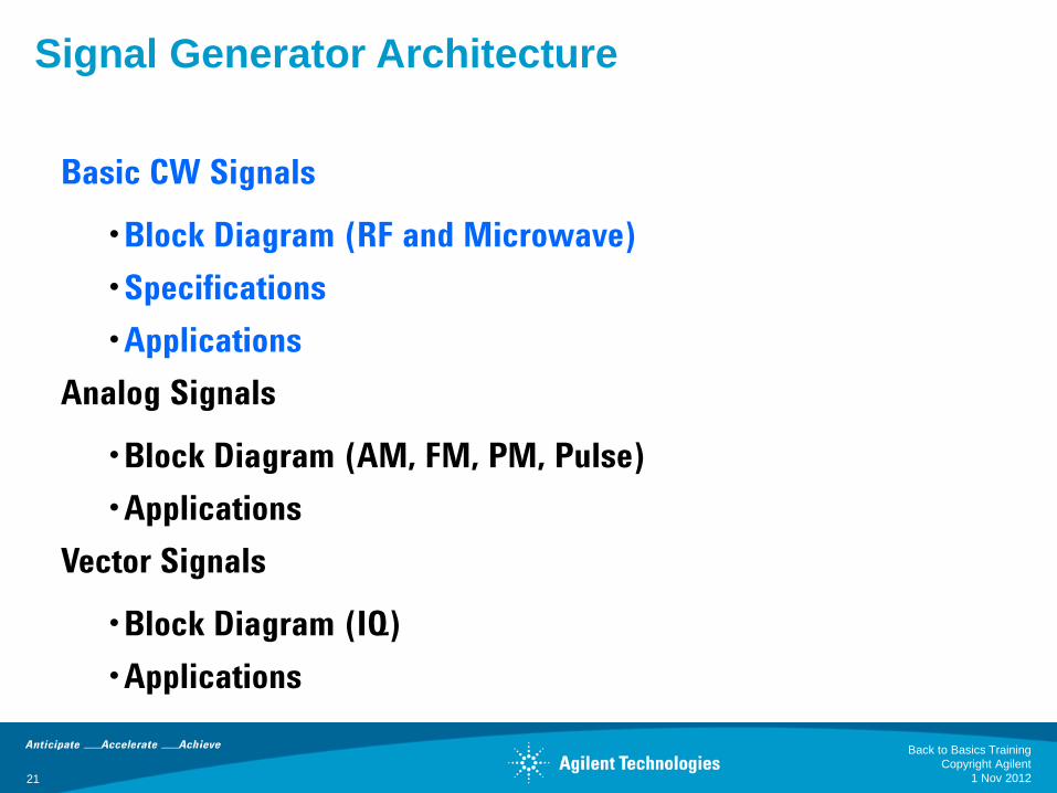
Signal Generator Architecture
Basic CW Signals
•Block Diagram (RF and Microwave)
•Specifications
•Applications
Analog Signals
•Block Diagram (AM, FM, PM, Pulse)
•Applications
Vector Signals
•Block Diagram (IQ)
•Applications
1 Nov 2012
Back to Basics Training
Copyright Agilent

Basic CW Signals – Block Diagram
Reference
Oscillator
VCO
Phase
Detector
Frac-N
divide
by X
ALC
Modulator
ALC
Driver
ALC Detector
Output
Attenuator
ALC = automatic level control Reference Section
Output Section Synthesizer Section
RF Source
f
1 Nov 2012
Back to Basics Training
Copyright Agilent
22
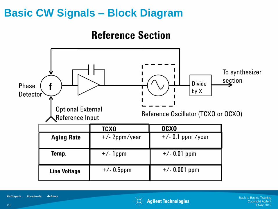
Basic CW Signals – Block Diagram
Phase
Detector
Optional External
Reference Input Reference Oscillator (TCXO or OCXO)
TCXO OCXO
Aging Rate +/- 2ppm/year +/- 0.1 ppm /year
Temp. +/- 1ppm +/- 0.01 ppm
+/- 0.5ppm +/- 0.001 ppm
To synthesizer
section Divide
by X
Reference Section
f
Line Voltage
1 Nov 2012
Back to Basics Training
Copyright Agilent
23

Basic CW Signals – Block Diagram
ALC
Modulator
ALC
Driver
ALC Detector
Output
Attenuator From
synthesizer
section Source
output
• ALC
•maintains level output power
by adding/subtracting power
as needed
• Output Attenuator
•mechanical or electronic
•provides attenuation to
achieve wide output range
(e.g. -127 dBm to +23 dBm)
Output Section
1 Nov 2012
Back to Basics Training
Copyright Agilent
24
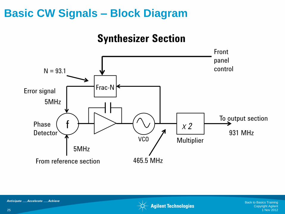
VCO
Phase
Detector
Frac-N
From reference section
To output section
X 2
Multiplier
Front
panel
control
5MHz
465.5 MHz
N = 93.1
931 MHz
5MHz
Synthesizer Section
Error signal
Basic CW Signals – Block Diagram
f
1 Nov 2012
Back to Basics Training
Copyright Agilent
25

Basic CW Signals – Block Diagram
Reference
oscillator
Overall phase noise of signal
VCO noise
Phase
detector
noise Broadband
noise floor
20logN
Phase-locked-loop (PLL) bandwidth
selected for optimum noise
performance
frequency
PLL/Fractional-N…suppress phase noise
1 Nov 2012
Back to Basics Training
Copyright Agilent
26
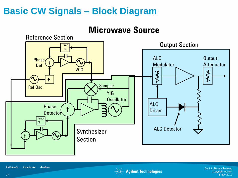
Basic CW Signals – Block Diagram
ALC Detector
ALC
Modulator
ALC
Driver
Output
Attenuator
Sampler
Reference Section
Synthesizer
Section
Output Section
Ref Osc
VCO
Phase
Det
Frac
N
f
Frac-
N
Phase
Detector
YIG
Oscillator
Microwave Source
f
1 Nov 2012
Back to Basics Training
Copyright Agilent
27

Basic CW Signals – Specifications P
ow
er
Frequency
Uncertainty
Range Fmin to Fmax
Resolution Smallest frequency increment
Accuracy How close is the indicated frequency
to the actual frequency?
Switching Speed How quickly can you change from
one frequency to another?
Accuracy =
= CW frequency = 1 GHz
= aging rate = 0.152 ppm/year
= time since last calibrated = 1 year
f CW
t aging cal t * *
f CW t aging
cal t
Accuracy =
152 Hz
Frequency
1 Nov 2012
Back to Basics Training
Copyright Agilent
28
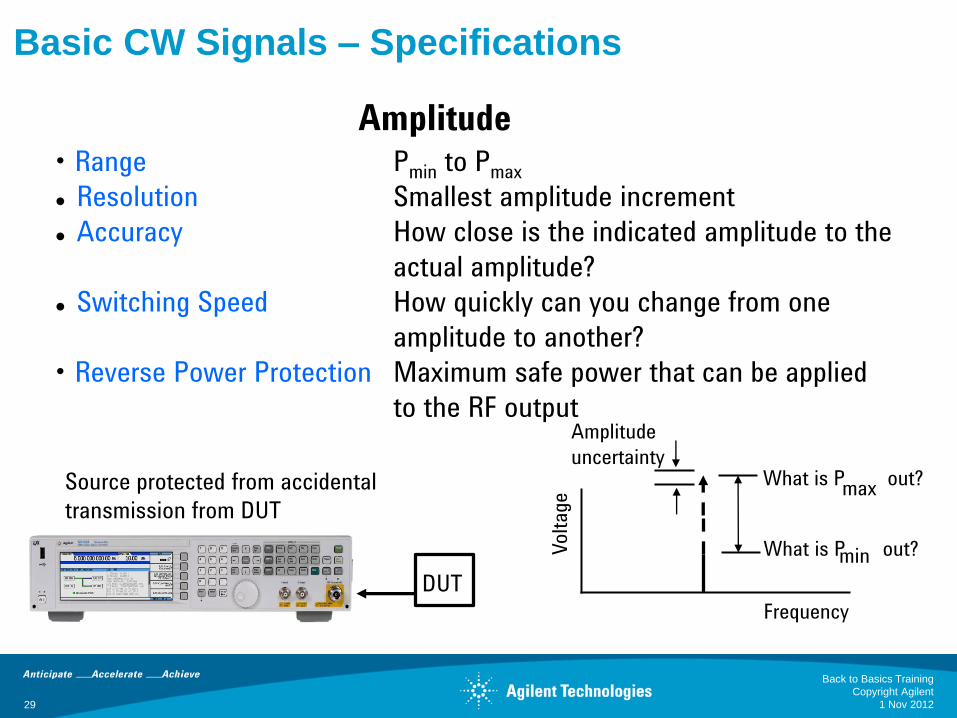
Basic CW Signals – Specifications
DUT
Source protected from accidental
transmission from DUT
Volt
age
Frequency
Amplitude
uncertainty What is P out?
max
min
• Range Pmin to Pmax
Resolution Smallest amplitude increment
Accuracy How close is the indicated amplitude to the
actual amplitude?
Switching Speed How quickly can you change from one
amplitude to another?
• Reverse Power Protection Maximum safe power that can be applied
to the RF output
What is P out?
Amplitude
1 Nov 2012
Back to Basics Training
Copyright Agilent
29
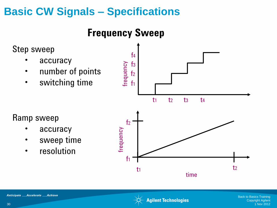
Basic CW Signals – Specifications
Ramp sweep
• accuracy
• sweep time
• resolution
Step sweep
• accuracy
• number of points
• switching time
time
f2
t2 t1
f1
t4 t3 t1 t2
f4
f3
f1
f2
Frequency Sweep
1 Nov 2012
Back to Basics Training
Copyright Agilent
30
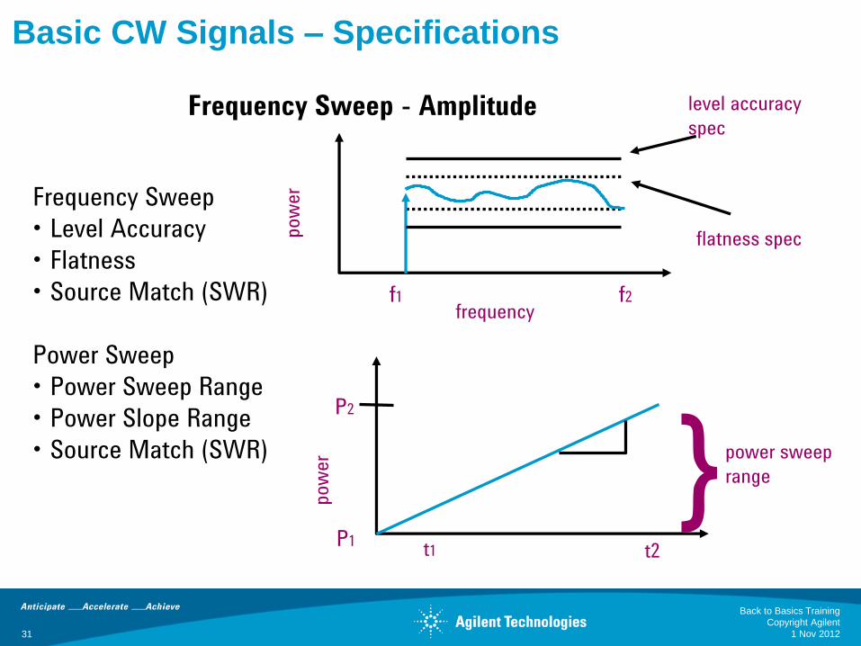
Basic CW Signals – Specifications
Frequency Sweep
• Level Accuracy
• Flatness
• Source Match (SWR)
Power Sweep
• Power Sweep Range
• Power Slope Range
• Source Match (SWR)
flatness spec
level accuracy
spec
f1 f2 frequency
pow
er
pow
er }
P2
P1
power sweep
range
t1 t2
Frequency Sweep - Amplitude
1 Nov 2012
Back to Basics Training
Copyright Agilent
31
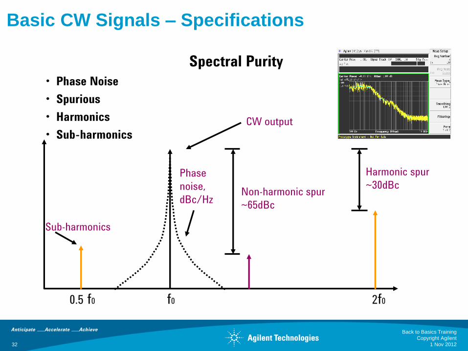
Basic CW Signals – Specifications
• Phase Noise
• Spurious
• Harmonics
• Sub-harmonics
Non-harmonic spur
~65dBc
Harmonic spur
~30dBc
CW output
Phase
noise,
dBc/Hz
0.5 f0 f0 2f0
Sub-harmonics
Spectral Purity
1 Nov 2012
Back to Basics Training
Copyright Agilent
32
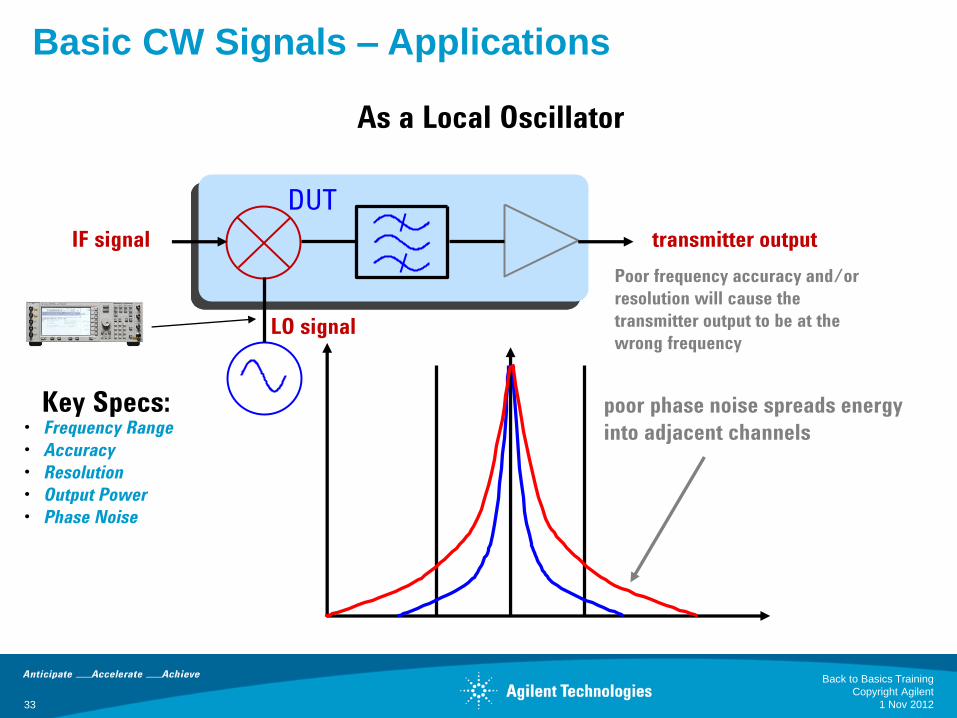
IF signal transmitter output
poor phase noise spreads energy
into adjacent channels
Poor frequency accuracy and/or
resolution will cause the
transmitter output to be at the
wrong frequency
DUT
• Frequency Range
• Accuracy
• Resolution
• Output Power
• Phase Noise
LO signal
Key Specs:
As a Local Oscillator
Basic CW Signals – Applications
1 Nov 2012
Back to Basics Training
Copyright Agilent
33

Frequency
Leve
l (d
Bm
)
IF signal
in-channel signal
(cw signal)
DUT
Receiver Sensitivity
The smallest RF signal that will produce a
desired baseband output from the receiver
IF Rejection Curve
source output
-116 dBm to –126
dBm
IF Channel
• Amplitude Range
• Amplitude Accuracy
• Amplitude Resolution
Key Specs:
Basic CW Signals – Applications
In-Channel Receiver Testing
1 Nov 2012
Back to Basics Training
Copyright Agilent
34
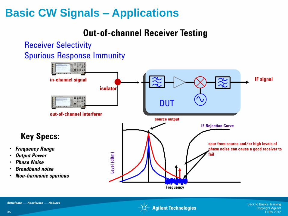
IF signal
out-of-channel interferer
DUT
Receiver Selectivity
Spurious Response Immunity
IF Rejection Curve
Frequency
Leve
l (d
Bm
)
spur from source and/or high levels of
phase noise can cause a good receiver to
fail
source output
• Frequency Range
• Output Power
• Phase Noise
• Broadband noise
• Non-harmonic spurious
Key Specs:
Basic CW Signals – Applications
Out-of-channel Receiver Testing
in-channel signal
isolator
1 Nov 2012
Back to Basics Training
Copyright Agilent
35
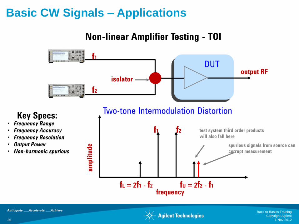
output RF
f1
f2
DUT
f2 f1
fU = 2f2 - f1 fL = 2f1 - f2
spurious signals from source can
corrupt measurement
frequency
test system third order products
will also fall here
isolator
Two-tone Intermodulation Distortion
• Frequency Range
• Frequency Accuracy
• Frequency Resolution
• Output Power
• Non-harmonic spurious
Key Specs:
Basic CW Signals – Applications
Non-linear Amplifier Testing - TOI
1 Nov 2012
Back to Basics Training
Copyright Agilent
36
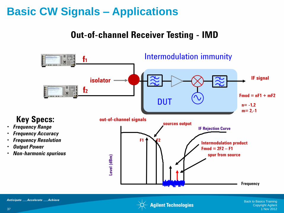
IF signal
out-of-channel signals
DUT
Intermodulation immunity
IF Rejection Curve
Frequency
Leve
l (d
Bm
) spur from source
sources output
isolator
Fmod = nF1 + mF2
n= -1,2
m= 2,-1
F1 F2 Intermodulation product
Fmod = 2F2 – F1
• Frequency Range
• Frequency Accuracy
• Frequency Resolution
• Output Power
• Non-harmonic spurious
Key Specs:
Basic CW Signals – Applications
Out-of-channel Receiver Testing - IMD
f1
f2
1 Nov 2012
Back to Basics Training
Copyright Agilent
37
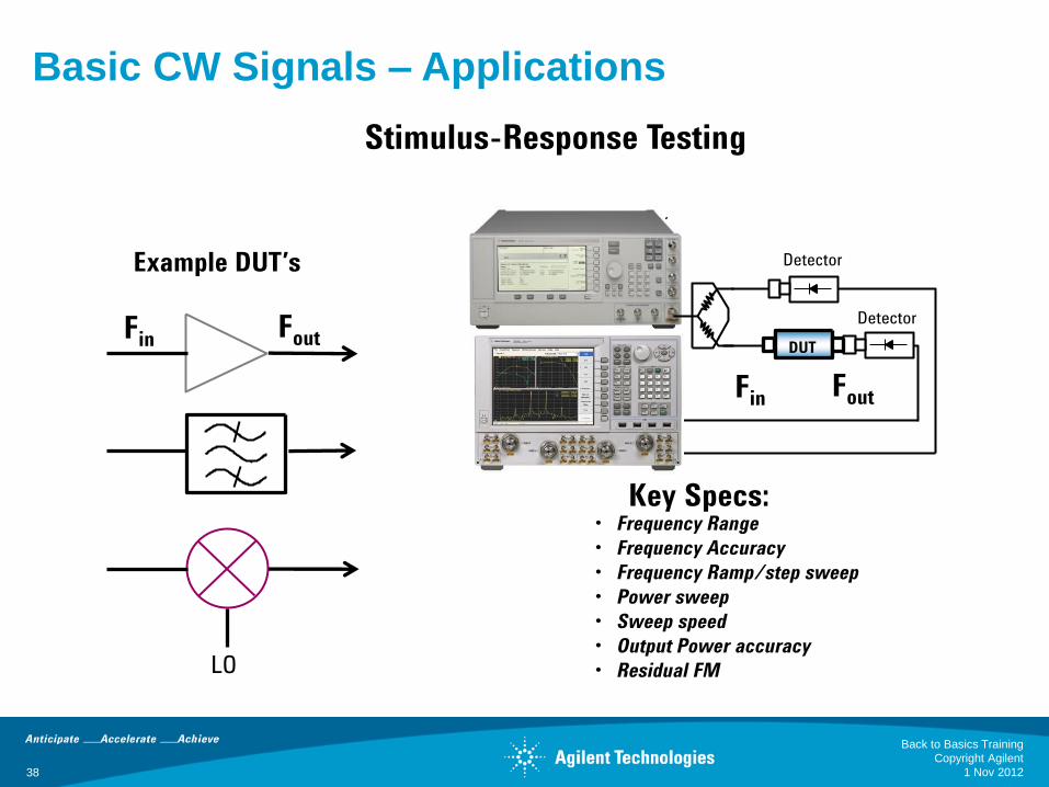
Detector
Detector
DUT
LO
Example DUT’s
Fin Fout
Fin Fout
• Frequency Range
• Frequency Accuracy
• Frequency Ramp/step sweep
• Power sweep
• Sweep speed
• Output Power accuracy
• Residual FM
Key Specs:
Basic CW Signals – Applications
Stimulus-Response Testing
1 Nov 2012
Back to Basics Training
Copyright Agilent
38
39
Signal Generators
Basic CW Signals
•Block Diagram (RF and Microwave)
•Specifications
•Applications
Analog Signals
•Block Diagram (AM, FM, PM, Pulse)
•Applications
Vector Signals
•Block Diagram (IQ)
•Applications
1 Nov 2012
Back to Basics Training
Copyright Agilent
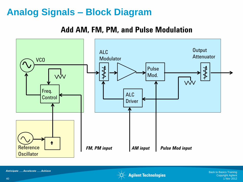
Freq.
Control
ALC
Modulator
Pulse
Mod.
Output
Attenuator
ALC
Driver
Reference
Oscillator
VCO
FM, PM input AM input Pulse Mod input
Analog Signals – Block Diagram
Add AM, FM, PM, and Pulse Modulation
1 Nov 2012
Back to Basics Training
Copyright Agilent
40
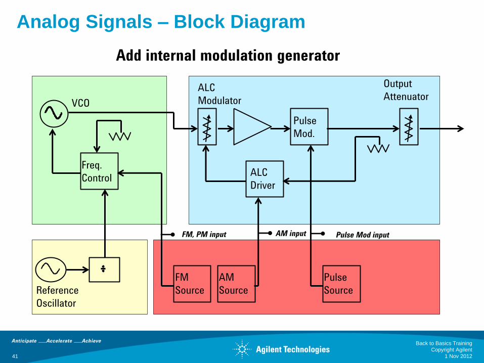
Freq.
Control
FM
Source
ALC
Modulator
Pulse
Mod.
Output
Attenuator
ALC
Driver
AM
Source
Pulse
Source Reference
Oscillator
VCO
FM, PM input AM input Pulse Mod input
Analog Signals – Block Diagram
Add internal modulation generator
1 Nov 2012
Back to Basics Training
Copyright Agilent
41
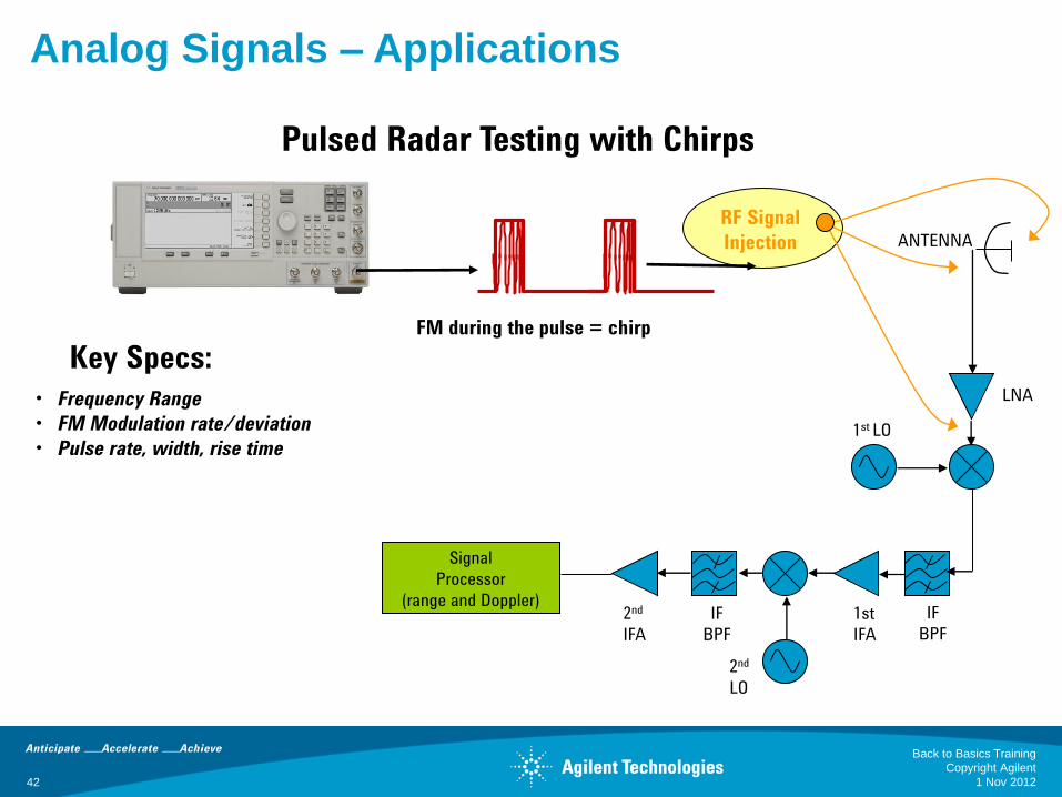
FM during the pulse = chirp
LNA
IF
BPF
Signal
Processor
(range and Doppler) 1st
IFA
2nd
LO
IF
BPF
2nd
IFA
ANTENNA
RF Signal
Injection
1st LO
• Frequency Range
• FM Modulation rate/deviation
• Pulse rate, width, rise time
Key Specs:
Analog Signals – Applications
Pulsed Radar Testing with Chirps
1 Nov 2012
Back to Basics Training
Copyright Agilent
42
43
Signal Generators
Basic CW Signals
•Block Diagram (RF and Microwave)
•Specifications
•Applications
Analog Signals
•Block Diagram (AM, FM, PM, Pulse)
•Applications
Vector Signals
•Block Diagram (IQ)
•Applications
1 Nov 2012
Back to Basics Training
Copyright Agilent
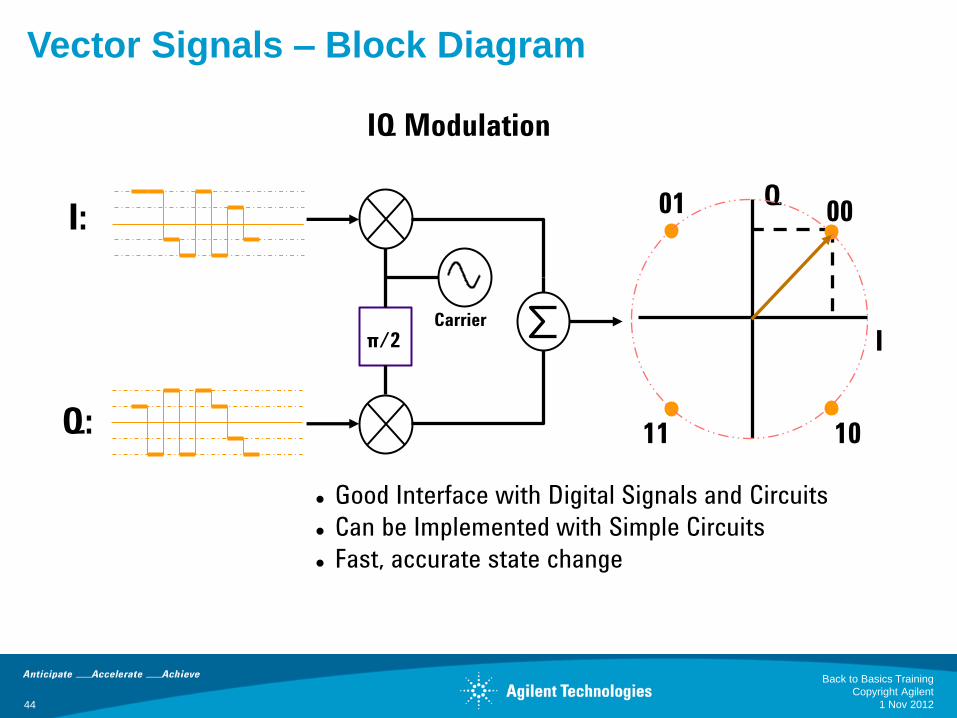
π/2 Carrier
I:
Q:
Good Interface with Digital Signals and Circuits
Can be Implemented with Simple Circuits
Fast, accurate state change
I
Q 00 01
10 11
Vector Signals – Block Diagram
IQ Modulation
1 Nov 2012
Back to Basics Training
Copyright Agilent
44
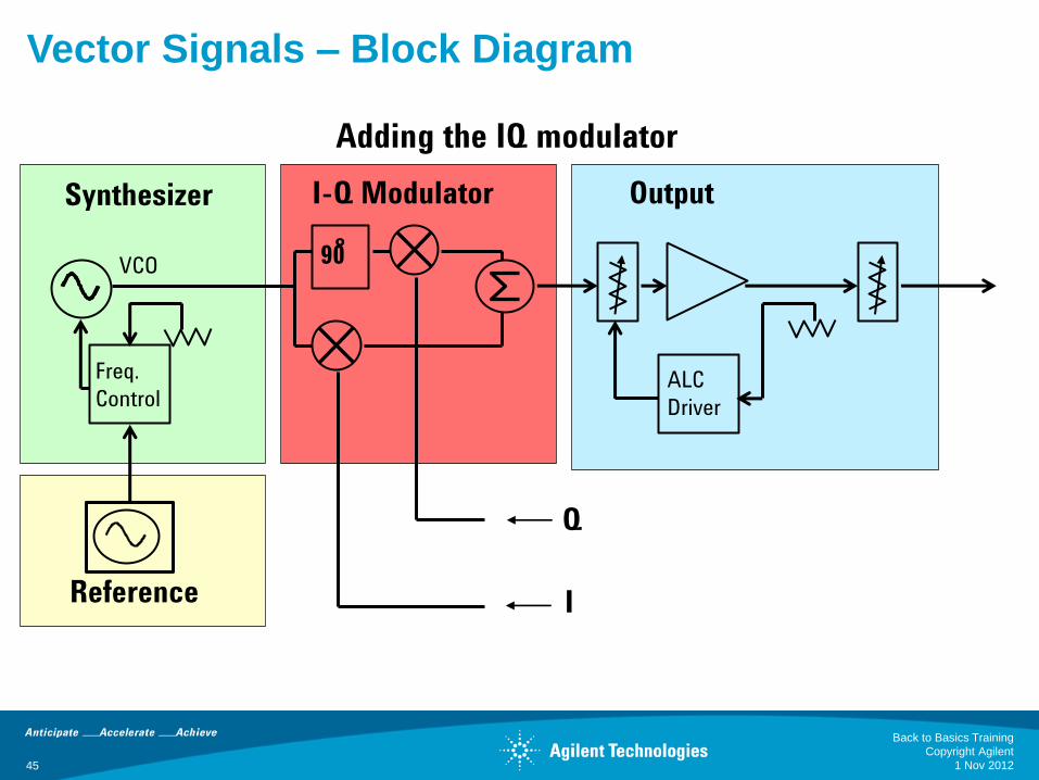
Freq.
Control ALC
Driver
VCO
Synthesizer
Reference
Output I-Q Modulator
90 ̊
Q
I
Adding the IQ modulator
Vector Signals – Block Diagram
1 Nov 2012
Back to Basics Training
Copyright Agilent
45
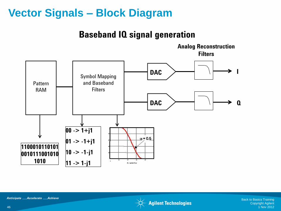
Pattern
RAM
Symbol Mapping
and Baseband
Filters
DAC
DAC
Analog Reconstruction
Filters
I
Q
1100010110101
0010111001010
1010
00 -> 1+j1
01 -> -1+j1
10 -> -1-j1
11 -> 1-j1
Vector Signals – Block Diagram
Baseband IQ signal generation
1 Nov 2012
Back to Basics Training
Copyright Agilent
46

Frequency
Frequency
Fast Transitions Require Wide Bandwidths
Filtering Slows Down Transitions and Narrows the Bandwidth
Baseband Generator: Baseband Filters
Vector Signals – Block Diagram
1 Nov 2012
Back to Basics Training
Copyright Agilent
47

Freq.
Control ALC
Driver
Pattern
RAM and
Symbol
Mapping
VCO
Synthesizer
Reference
Output I-Q Modulator
Baseband Generator
p/2
DAC
DAC
Q
I
Vector Signals – Block Diagram
Adding an internal Baseband Generator
1 Nov 2012
Back to Basics Training
Copyright Agilent
48
49
Format Specific Signal Generation
Receiver Sensitivity
Receiver Selectivity
Component Distortion
Vector Signals – Applications
1 Nov 2012
Back to Basics Training
Copyright Agilent

FDMA TDMA
CDMA OFDM
Vector Signals – Applications
Digital Format Access Schemes
One User
Different time - different Users
Differ channel - different Users Different time - different Users
Same channel – many users
1 Nov 2012
Back to Basics Training
Copyright Agilent
50
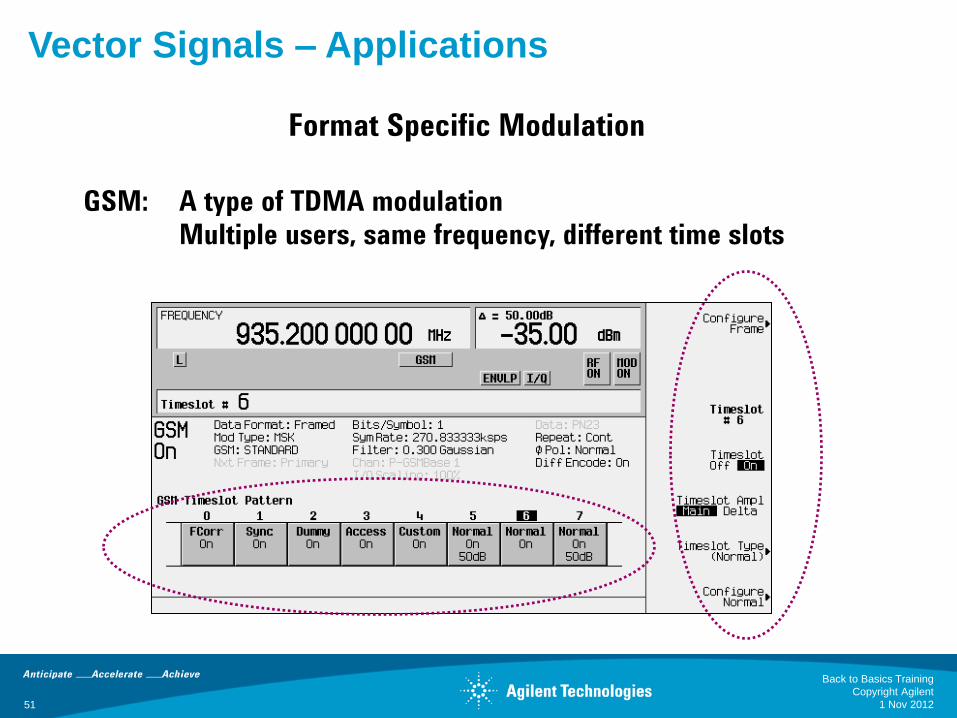
GSM: A type of TDMA modulation
Multiple users, same frequency, different time slots
Vector Signals – Applications
Format Specific Modulation
1 Nov 2012
Back to Basics Training
Copyright Agilent
51

Baseband
DSP
RF
RF LO
DAC
Payload Data
DUT
frequency
Am
plit
ude
BER Spec Line
BER
The smallest modulated RF signal that will produce
a specified BER from the receiver
Vector Signals – Applications
Digital Receiver Sensitivity
1 Nov 2012
Back to Basics Training
Copyright Agilent
52
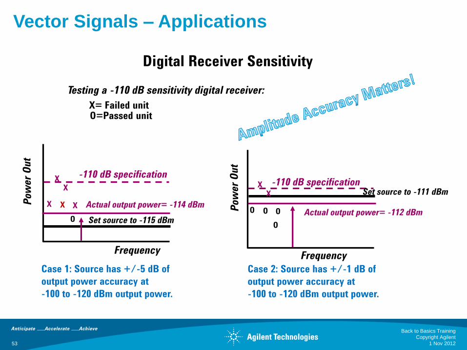
Testing a -110 dB sensitivity digital receiver:
-110 dB specification
Case 1: Source has +/-5 dB of
output power accuracy at
-100 to -120 dBm output power.
Set source to -115 dBm
Actual output power= -114 dBm
X X
X X X
O
Case 2: Source has +/-1 dB of
output power accuracy at
-100 to -120 dBm output power.
-110 dB specification Set source to -111 dBm
Actual output power= -112 dBm
X X
O O O
O
X= Failed unit O=Passed unit
Frequency Frequency
Vector Signals – Applications
Digital Receiver Sensitivity
1 Nov 2012
Back to Basics Training
Copyright Agilent
53
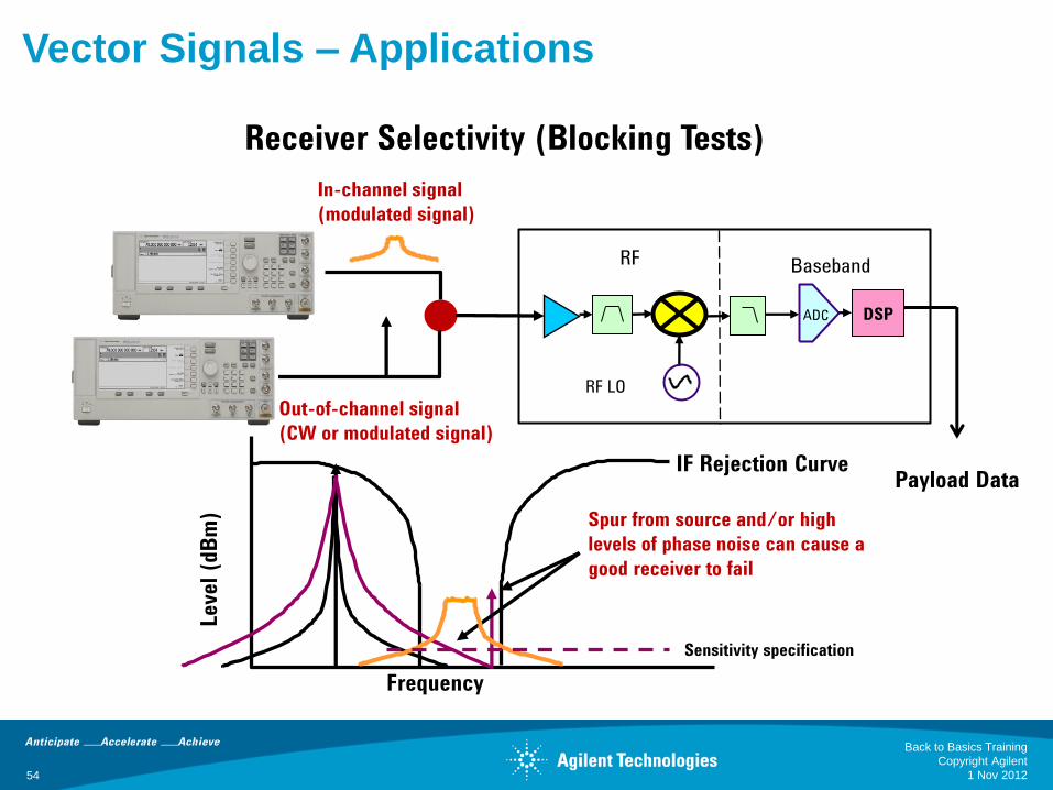
IF Rejection Curve
Frequency
Leve
l (d
Bm
) Spur from source and/or high
levels of phase noise can cause a
good receiver to fail
In-channel signal
(modulated signal)
Out-of-channel signal
(CW or modulated signal)
Baseband
DSP
RF
RF LO
DAC
Payload Data
Sensitivity specification
Vector Signals – Applications
Receiver Selectivity (Blocking Tests)
1 Nov 2012
Back to Basics Training
Copyright Agilent
54
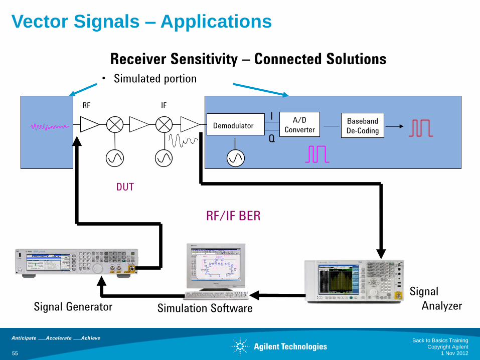
Demodulator
RF IF
Baseband
De-Coding
RF/IF BER
A/D
Converter
I
Q
Signal Generator
• Simulated portion
Signal
Analyzer Simulation Software
Vector Signals – Applications
Receiver Sensitivity – Connected Solutions
DUT
1 Nov 2012
Back to Basics Training
Copyright Agilent
55
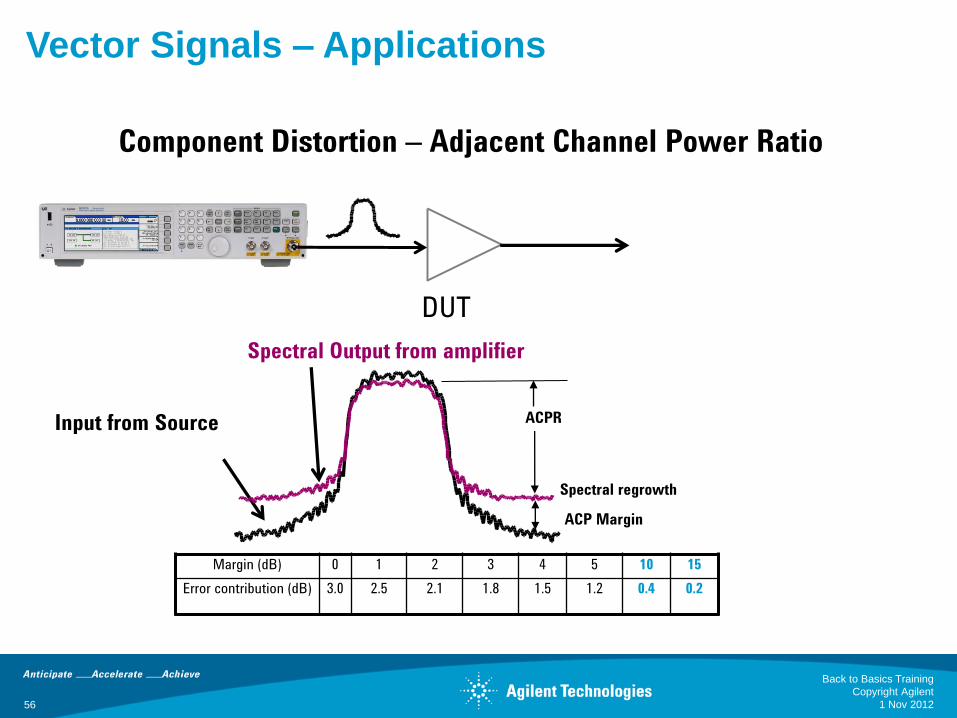
Input from Source
Spectral Output from amplifier
DUT
Spectral regrowth
ACPR
Margin (dB) 0 1 2 3 4 5 10 15
Error contribution (dB) 3.0 2.5 2.1 1.8 1.5 1.2 0.4 0.2
ACP Margin
Vector Signals – Applications
Component Distortion – Adjacent Channel Power Ratio
1 Nov 2012
Back to Basics Training
Copyright Agilent
56
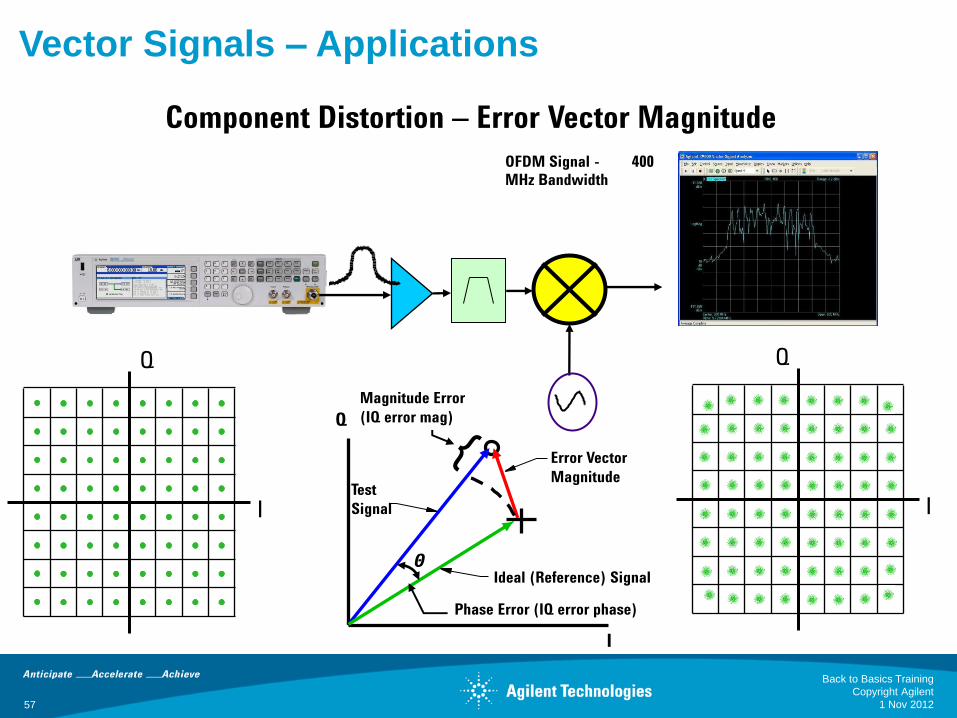
DAC
Q
I
Q
I
I
Q
Magnitude Error
(IQ error mag)
Error Vector
Magnitude
Ideal (Reference) Signal
Phase Error (IQ error phase)
Test
Signal
Θ
OFDM Signal - 400
MHz Bandwidth
Vector Signals – Applications
Component Distortion – Error Vector Magnitude
1 Nov 2012
Back to Basics Training
Copyright Agilent
57

Measured EVM = -30 dB, 3.3% Component Distortion – EVM
Vector Signals – Applications
OFDM Signal -
400 MHz Bandwidth
1 Nov 2012
Back to Basics Training
Copyright Agilent
58
59
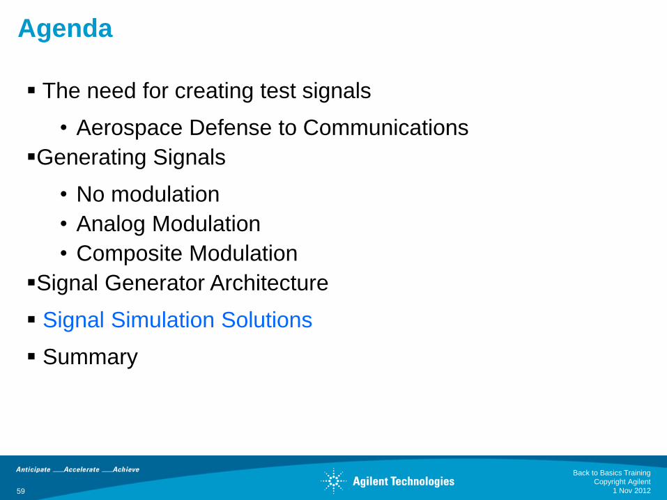
Agenda
The need for creating test signals
• Aerospace Defense to Communications
Generating Signals
• No modulation
• Analog Modulation
• Composite Modulation
Signal Generator Architecture
Signal Simulation Solutions
Summary
1 Nov 2012
Back to Basics Training
Copyright Agilent
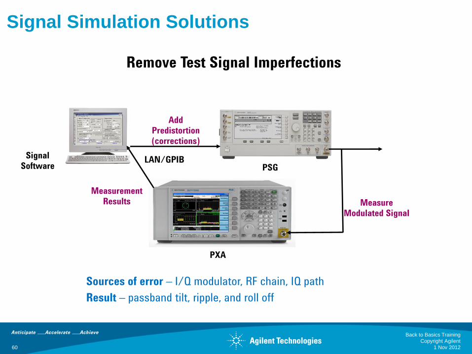
Remove Test Signal Imperfections
PSG
Signal
Software
PXA
LAN/GPIB
Measure
Modulated Signal
Measurement
Results
Signal Simulation Solutions
Add
Predistortion
(corrections)
Sources of error – I/Q modulator, RF chain, IQ path
Result – passband tilt, ripple, and roll off
1 Nov 2012
Back to Basics Training
Copyright Agilent
60
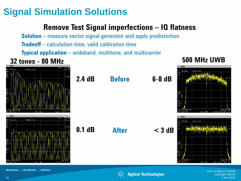
Remove Test Signal imperfections – IQ flatness Solution – measure vector signal generator and apply predistortion
Tradeoff – calculation time, valid calibration time
Typical application – wideband, multitone, and multicarrier
Before
After
2.4 dB
0.1 dB
6-8 dB
< 3 dB
500 MHz UWB 32 tones - 80 MHz
Signal Simulation Solutions
1 Nov 2012
Back to Basics Training
Copyright Agilent
61

Removing Test Signal Imperfections - IMD
Before Predistortion
Measured in-band IMD = -40 dBc
After Predistortion
Measured in-band IMD = -84 dBc
Signal Simulation Solutions
1 Nov 2012
Back to Basics Training
Copyright Agilent
62
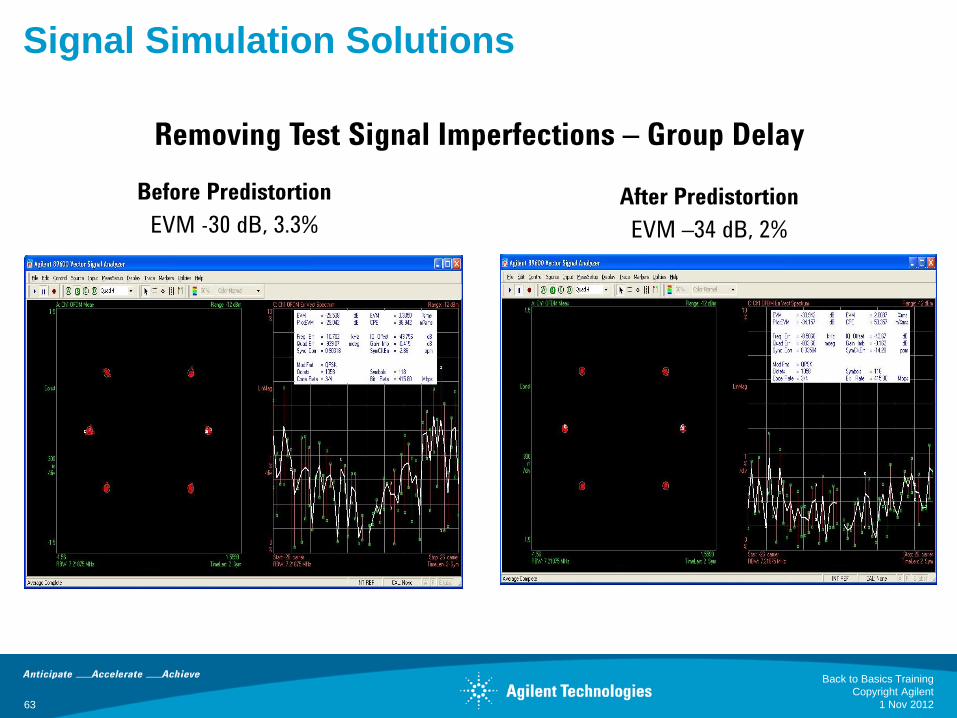
Removing Test Signal Imperfections – Group Delay
Before Predistortion
EVM -30 dB, 3.3%
After Predistortion
EVM –34 dB, 2%
Signal Simulation Solutions
1 Nov 2012
Back to Basics Training
Copyright Agilent
63
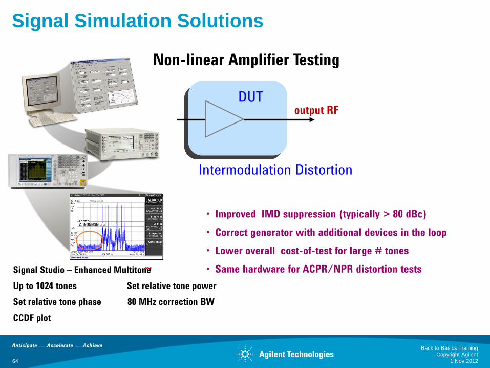
output RF DUT
Intermodulation Distortion
Signal Studio – Enhanced Multitone
Up to 1024 tones Set relative tone power
Set relative tone phase 80 MHz correction BW
CCDF plot
• Improved IMD suppression (typically > 80 dBc)
• Correct generator with additional devices in the loop
• Lower overall cost-of-test for large # tones
• Same hardware for ACPR/NPR distortion tests
Non-linear Amplifier Testing
Signal Simulation Solutions
1 Nov 2012
Back to Basics Training
Copyright Agilent
64
65
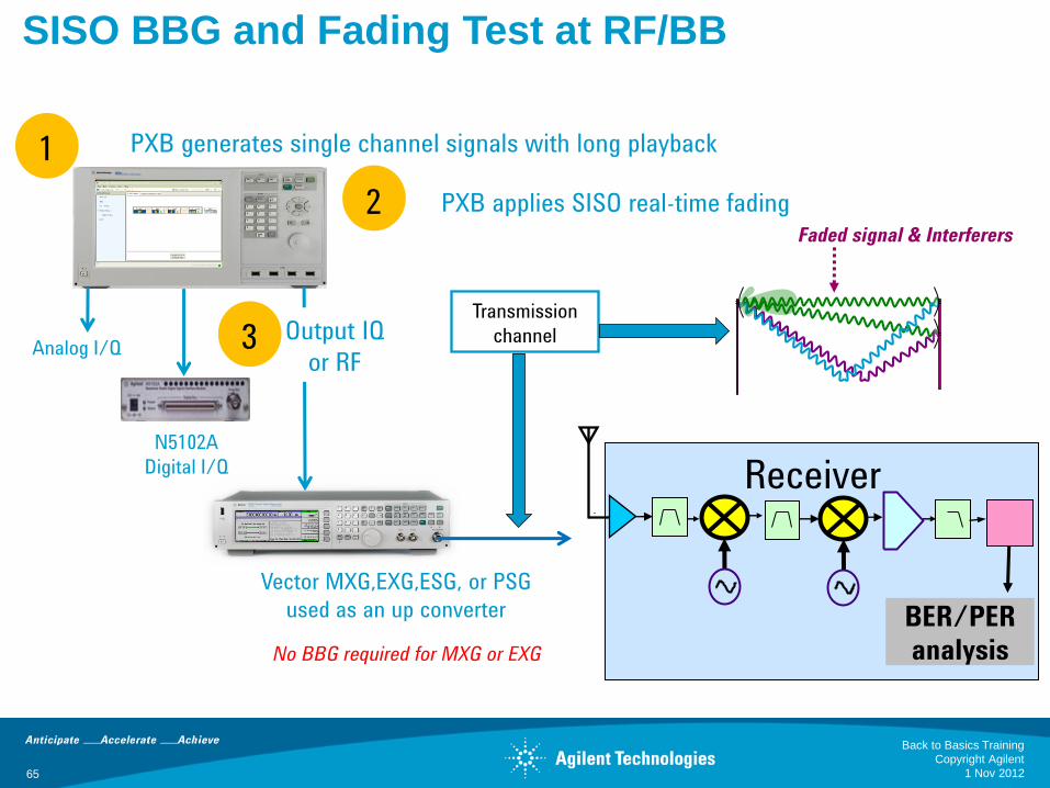
SISO BBG and Fading Test at RF/BB Simulate one Tx, one Rx, and apply real-time fading
1
2
PXB generates single channel signals with long playback
Vector MXG,EXG,ESG, or PSG
used as an up converter
PXB applies SISO real-time fading
No BBG required for MXG or EXG
Receiver
Faded signal & Interferers
BER/PER
analysis
Transmission
channel Analog I/Q
N5102A
Digital I/Q
Output IQ
or RF 3
1 Nov 2012
Back to Basics Training
Copyright Agilent
66
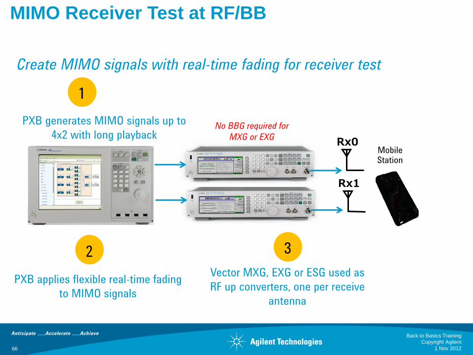
MIMO Receiver Test at RF/BB
Rx0
1
2
PXB generates MIMO signals up to
4x2 with long playback
3
Vector MXG, EXG or ESG used as
RF up converters, one per receive
antenna
PXB applies flexible real-time fading
to MIMO signals
Rx1
No BBG required for
MXG or EXG
Mobile Station
Create MIMO signals with real-time fading for receiver test
1 Nov 2012
Back to Basics Training
Copyright Agilent
67
Agenda
The need for creating test signals
• Aerospace Defense to Communications
Generating Signals
• No modulation
• Analog Modulation
• Composite Modulation
Signal Generator Architecture
Signal Simulation Solutions
Summary
1 Nov 2012
Back to Basics Training
Copyright Agilent
3.2 or 9 GHz World class SSB phase noise
68
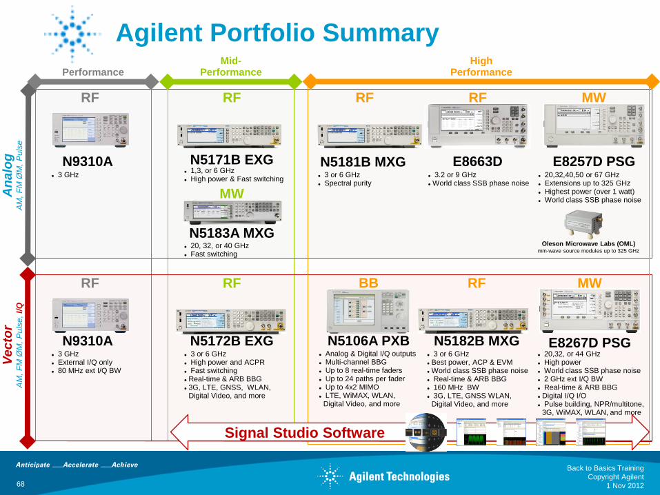
Agilent Portfolio Summary Basic
Performance
E8257D PSG
MW
High Performance
E8663D N5181B MXG
RF
E8267D PSG
MW
N5182B MXG
RF
RF
N5171B EXG
RF
N5172B EXG
RF
Mid- Performance
N9310A
RF
N9310A
RF
An
alo
g
AM
, F
M Ø
M,
Pu
lse
Ve
cto
r A
M,
FM
ØM
, P
uls
e, I/
Q
3 or 6 GHz Best power, ACP & EVM World class SSB phase noise Real-time & ARB BBG 160 MHz BW 3G, LTE, GNSS WLAN,
Digital Video, and more
20,32, or 44 GHz High power World class SSB phase noise 2 GHz ext I/Q BW Real-time & ARB BBG Digital I/Q I/O Pulse building, NPR/multitone,
3G, WiMAX, WLAN, and more
3 or 6 GHz High power and ACPR Fast switching Real-time & ARB BBG 3G, LTE, GNSS, WLAN,
Digital Video, and more
3 GHz External I/Q only 80 MHz ext I/Q BW
3 or 6 GHz Spectral purity
20,32,40,50 or 67 GHz Extensions up to 325 GHz Highest power (over 1 watt) World class SSB phase noise
1,3, or 6 GHz High power & Fast switching
3 GHz
N5183A MXG 20, 32, or 40 GHz Fast switching
MW
Oleson Microwave Labs (OML) mm-wave source modules up to 325 GHz
N5106A PXB
BB
Analog & Digital I/Q outputs Multi-channel BBG Up to 8 real-time faders Up to 24 paths per fader Up to 4x2 MIMO LTE, WiMAX, WLAN,
Digital Video, and more
Signal Studio Software
1 Nov 2012
Back to Basics Training
Copyright Agilent
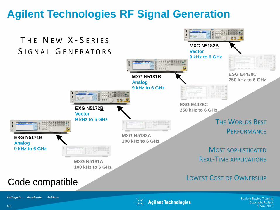
AGILENT TECHNOLOGIES’ RF SIGNAL GENERATION
MXG N5182A
100 kHz to 6 GHz
ESG E4428C
250 kHz to 6 GHz
MXG N5181B
Analog
9 kHz to 6 GHz
ESG E4438C
250 kHz to 6 GHz
EXG N5171B
Analog
9 kHz to 6 GHz
MXG N5181A
100 kHz to 6 GHz
EXG N5172B
Vector
9 kHz to 6 GHz
MXG N5182B
Vector
9 kHz to 6 GHz
THE WORLDS BEST PERFORMANCE
MOST SOPHISTICATED
REAL-TIME APPLICATIONS
LOWEST COST OF OWNERSHIP
T H E N E W X - S E R I E S S I G N A L G E N E R A T O R S
Code compatible
Agilent Technologies RF Signal Generation
1 Nov 2012 69
Back to Basics Training
Copyright Agilent
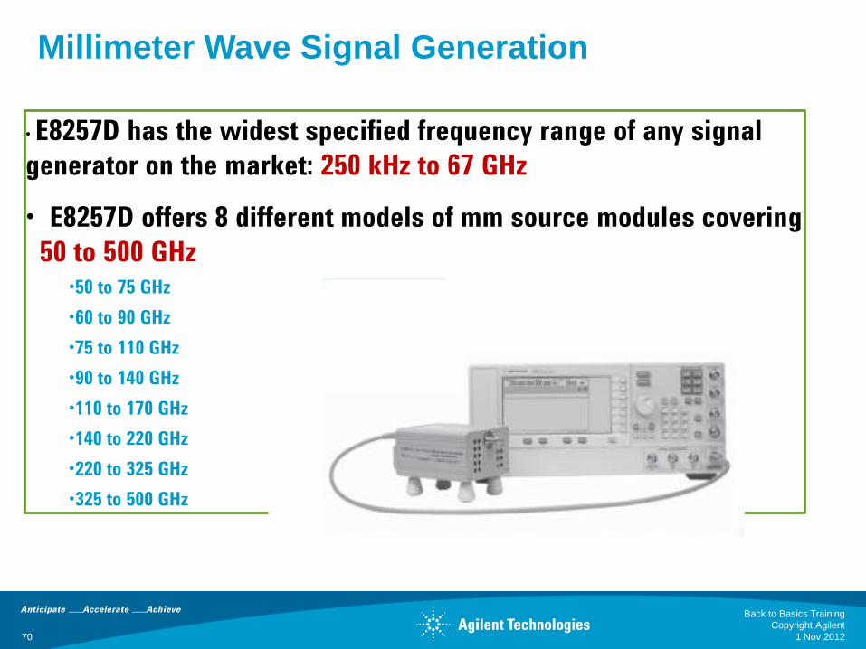
• E8257D has the widest specified frequency range of any signal
generator on the market: 250 kHz to 67 GHz
• E8257D offers 8 different models of mm source modules covering
50 to 500 GHz •50 to 75 GHz
•60 to 90 GHz
•75 to 110 GHz
•90 to 140 GHz
•110 to 170 GHz
•140 to 220 GHz
•220 to 325 GHz
•325 to 500 GHz
Millimeter Wave Signal Generation
70 1 Nov 2012
Back to Basics Training
Copyright Agilent
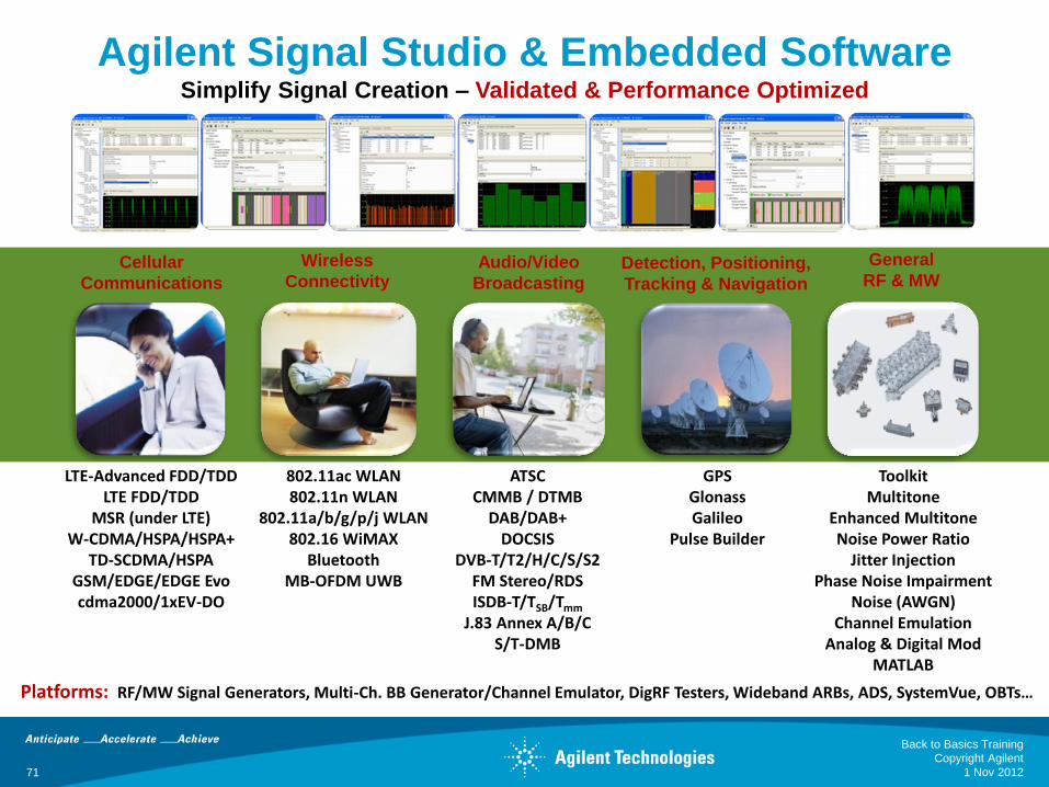
Agilent Signal Studio & Embedded Software Simplify Signal Creation – Validated & Performance Optimized
LTE-Advanced FDD/TDD LTE FDD/TDD
MSR (under LTE) W-CDMA/HSPA/HSPA+
TD-SCDMA/HSPA GSM/EDGE/EDGE Evo cdma2000/1xEV-DO
802.11ac WLAN 802.11n WLAN
802.11a/b/g/p/j WLAN 802.16 WiMAX
Bluetooth MB-OFDM UWB
ATSC CMMB / DTMB
DAB/DAB+ DOCSIS
DVB-T/T2/H/C/S/S2 FM Stereo/RDS ISDB-T/TSB/Tmm
J.83 Annex A/B/C S/T-DMB
Toolkit Multitone
Enhanced Multitone Noise Power Ratio
Jitter Injection Phase Noise Impairment
Noise (AWGN) Channel Emulation
Analog & Digital Mod MATLAB
GPS Glonass Galileo
Pulse Builder
Cellular
Communications
Wireless
Connectivity Audio/Video
Broadcasting
General
RF & MW Detection, Positioning,
Tracking & Navigation
Platforms: RF/MW Signal Generators, Multi-Ch. BB Generator/Channel Emulator, DigRF Testers, Wideband ARBs, ADS, SystemVue, OBTs…
1 Nov 2012 71
Back to Basics Training
Copyright Agilent
For Additional Information
Sources: http://www.agilent.com/find/sources
Signal Analyzers: http://www.agilent.com/find/sa
Recorded webcast : Back to Basics: Signal Analysis
1 Nov 2012
Back to Basics Training
Copyright Agilent
72

73
THANK YOU!
1 Nov 2012
Back to Basics Training
Copyright Agilent