Embed Size (px)
Citation preview

I
BACHELOR THESIS
To acquire the academic degree B.Sc.
Topic: Development of a mobile audiovisual hardware-based system for training purposes Scientific institution: Hamburg University of Applied Sciences Department Media Technology Submitted by: Hannes Winkel – 2088879 In cooperation with: Bond Technology Management Delivered on: 21.09.2015, Hamburg First examiner: Prof. Dr. Robert Mores Second examiner: Prof. Dr. Ralf Hendrych

II
Abstract
Nowadays staff trainings in the media technology sector have a prime
importance as the technologies are evolving more frequently than ever.
This thesis shows how a training environment can be designed which allows
training participants to get in touch with new media technologies during a
training course. Therefore the criteria for the selection of the right
hardware which is serving the purpose of such trainings are depicted. On
the basis of a training concept for engineers on private superyachts a
mobile training unit was developed which is used for the implementation
of hands-on exercises during the courses.
III
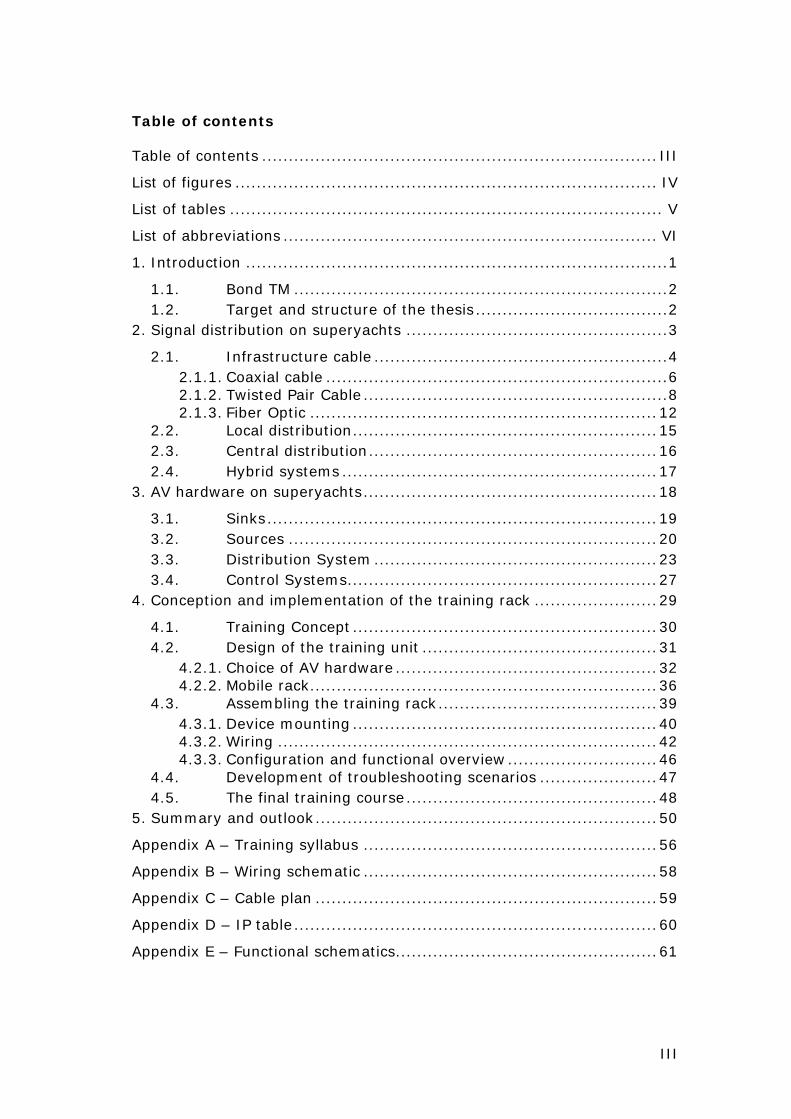
Table of contents
Table of contents .......................................................................... III
List of figures ............................................................................... IV
List of tables ................................................................................. V
List of abbreviations ...................................................................... VI
1. Introduction ............................................................................... 1
1.1. Bond TM ...................................................................... 2 1.2. Target and structure of the thesis .................................... 2
2. Signal distribution on superyachts ................................................. 3
2.1. Infrastructure cable ....................................................... 4 2.1.1. Coaxial cable ................................................................ 6 2.1.2. Twisted Pair Cable ......................................................... 8 2.1.3. Fiber Optic ................................................................. 12
2.2. Local distribution ......................................................... 15 2.3. Central distribution ...................................................... 16 2.4. Hybrid systems ........................................................... 17
3. AV hardware on superyachts ....................................................... 18
3.1. Sinks ......................................................................... 19 3.2. Sources ..................................................................... 20 3.3. Distribution System ..................................................... 23 3.4. Control Systems .......................................................... 27
4. Conception and implementation of the training rack ....................... 29
4.1. Training Concept ......................................................... 30 4.2. Design of the training unit ............................................ 31
4.2.1. Choice of AV hardware ................................................. 32 4.2.2. Mobile rack ................................................................. 36
4.3. Assembling the training rack ......................................... 39 4.3.1. Device mounting ......................................................... 40 4.3.2. Wiring ....................................................................... 42 4.3.3. Configuration and functional overview ............................ 46
4.4. Development of troubleshooting scenarios ...................... 47 4.5. The final training course ............................................... 48
5. Summary and outlook ................................................................ 50
Appendix A – Training syllabus ....................................................... 56
Appendix B – Wiring schematic ....................................................... 58
Appendix C – Cable plan ................................................................ 59
Appendix D – IP table .................................................................... 60
Appendix E – Functional schematics ................................................. 61
IV
List of figures
Figure 1: Cross section of a multicore cable showing the coax, twisted
pair and fiber optic cables .................................................. 4
Figure 2: Hardware distribution levels based on three different kinds
of equipment centres ........................................................ 6
Figure 3: Coaxial Cable Structure ...................................................... 7
Figure 4: Twisted Pair Cable Structure (S/UTP) ................................... 8
Figure 5: Fiber optic cable structure ................................................ 12
Figure 6: Multimode and singlemode fiber index types ....................... 14
Figure 7: Local distribution schematic of an exemplary guest cabin ...... 16
Figure 8: Central distribution systems .............................................. 17
Figure 9: Overview of AV hardware and their interconnection on a
yacht ............................................................................ 18
Figure 10: HDMI to RF modulator .................................................... 24
Figure 11: 32x32 Lightware matrix frame with various I/O boards ....... 25
Figure 12: Schematic of cascading AV matrices ................................. 25
Figure 13: Rear view of a Crestron CP3 control processor with
different control interfaces ............................................. 28
Figure 14: Control Devices: Crestron remote, keypad and Apple iPad
with a Crestron GUI ....................................................... 29
Figure 15: 19-Inch rack at the Jetstream datacenter .......................... 32
Figure 16: Front and rear view of the 17x17 Lightware matrix ............. 33
Figure 17: AV rack allocation schematic ........................................... 36
Figure 18: Rack frame dimensions ................................................... 37
Figure 19: Double-door and case-in-case flightcases from Amptown ..... 38
Figure 20: Custom double-door rack from Amptown .......................... 39
Figure 21: Custom made rack mount for the AV receiver .................... 41
Figure 22: Testing the hardware with lose cabling ............................. 42
Figure 23: Attached power supplies and shortened power cords ........... 43
Figure 24: Final internal rack cabling ............................................... 44
Figure 25: Front view of the final training rack .................................. 45
Figure 26: Setup at the first training course at the Bond office in
Amsterdam ................................................................ 49

V
List of tables
Table 1: Cable types according to ISO/IEC-11801 ............................... 9
Table 2: Categories of twisted pair cables ........................................ 11
Table 3: Fibre optic cable types ....................................................... 14
Table 4: In-Rack hardware description ............................................. 34
Table 5: External hardware description ............................................ 35
Table 6: Miscellaneous hardware description ..................................... 35
Table 7: Troubleshooting scenarios for the AV training ....................... 48

VI
List of abbreviations
AV: Audiovisual
ETO: Electro-Technical Officer
RF: Radio Frequency
IP: Internet Protocol
IR: Infrared
HDMI: High Definition Multimedia Interface
TPS: Twisted Pair Shielded
CAT: Category
Coax: Coaxial cable
FO: Fiber optic cable
MEC: Main Equipment Center
BEC: Branch Equipment Center
LEC: Local Equipment Center
LOA: Length Overall
RX. Receiver
TX: Transmitter
LAN: Local Area Network
OLED: Organic Light Emitting Diode
VoD: Video on Demand
AVoD: Audio/Video on Demand
DtO: Download to Own
HD: High Definition
GUI: Graphical User Interface
TVRO: Television Receive Only
BYOD: Bring Your Own Device
RU: Rack Unit
DMR: Digital Media Renderer
PYA: Professional Yachting Association
1
1. Introduction
“Not having heard is not as good as having heard, having heard is not as good as
having seen, having seen is not as good as mentally knowing, mentally knowing
is not as good as putting into action; true learning is complete only when action
has been put forth.”1
This quotation of a Chinese philosopher that lived from 312-230 BC shows that
practical training was already an axiom centuries ago. The way how we learn has
not changed since but it is often forgotten that only with practice the process of
learning is successful.
This applies in particular at technical trainings where complex systems and
functionalities are mediated. Those course contents need to be taught with the
support of practical examples where the training participants can apply the
theoretical knowledge.
This thesis handles the conception of such a technical training course with the
subject of AV systems on superyachts. In particular a training unit, based on AV
hardware, shall be built to allow the participants to gain hands-on experience at
the training course.
As complex AV systems on superyachts are a relatively new branch of the yachting
industry it is always a subject to change. This is due in part to the fact that
generally AV systems are also a fast moving area. This makes it even more
important to provide training courses for yacht crew members who are involved in
the AV system on board. Although larger yachts (> 100 m) often got a skilled
Electro Technical Officer (ETO) who is responsible for the AV system, often an
engineer who is not trained needs to maintain those systems.
Certainly a lot of technical trainings for yacht crew members are offered but none
of them occupies the AV part on board. To fill this gap the company Bond
Technology Management (in the following stated as Bond) has decided to create a
training course which shall mediate the basics of AV technologies on superyachts.
1 Liu Xiang, Xunzi - Ruxiao, chapter 11.

2
A main requirement on the training was that the trainees can gain real hands-on
experience during the course. For that reason the development of a mobile training
unit was demanded.
1.1. Bond TM
Bond Technology Management is a project management company specialized in
AV, IT, communications, security and navigation systems on superyachts. From
the first concept to the commissioning of completed yachts, Bond is supporting the
whole procedure of the integration of the respective systems and is helping to save
time and budgetary targets during the build of yachts. The same services are also
offered for residential projects although it is a secondary branch of business.
Bond was founded in 2007 and is actually represented in six countries with about
40 employees.
1.2. Target and structure of the thesis
The target of this thesis is the development of a mobile training unit that will be
used at basic AV technology training courses. The development comprises the
conception, construction and the documentation of the hardware based unit.
Chapter 2 of this thesis is transferring the basic knowledge of the signal distribution
on superyachts as a foundation for the construction of the training unit. Chapter 3
procures an overview and an evaluation of the significance of typical AV hardware
that is used on private superyachts.
These sections help to understand why particular decisions were made during the
construction phase of the training unit. Also because there is barely any specialised
literature about AV systems on yachts, these sections are giving an insight about
the usage of AV hardware on those special vessels.
In chapter 4 the actual conception and construction of the training rack is described
as well as the first application in an actual training course. Chapter 5 is
summarizing the result of the thesis and gives and outlook.
The development of the specific training content is not a part of this paper as it
would exceed the extent and topic of the thesis.

3
2. Signal distribution on superyachts
This chapter describes the different kinds of distributing audio and video signals
on superyachts.
The possibilities to distribute a signal from a source to a sink especially in the
digital signal process are immense and can quickly become a complex task to
overcome on a large vessel. Therefore it is mandatory to distinguish and
understand the different ways a signal can be distributed.
A basic requirement of the AV system on a yacht is that the user experience of the
entertainment system does not differ from the one at real estates. This entails that
most of the end user devices that are used at a yacht are common consumer
devices without any optimized connections for the infrastructure cabling of a
vessel. In addition, there is a large number of different consumer devices that
needs to be integrated because of the high standards and custom requirements of
the entertainment system on board. Although a HDMI interface is almost available
at every consumer device, those connections are very limited regarding their
maximum cable length and reliability.2 Since most of the AV sources are not
located in the same area as the displays and speakers, long cable runs need to be
overcome and cannot be realized through a HDMI connection. Also the HDMI
specification does not state a maximum cable length, experience shows that
distances above 20 meter are the critical point where the signal starts to drop.3
This approx. value depends on various attributes like the quality of the cable and
the connector itself, the data rate of the signal, the source of the signal and the
sink. As a consequence of those uncertain factors a point to point signal distribution
via HDMI should be avoided if source and sink are not serried. The implementation
of both distribution variants weather the source is located nearby or remote from
the sink is described in detail in chapter 2.2 and 2.3.
2 Cf. Somers, Steve: DVI and HDMI, 2015. 3 Cf. n.u.: Running Long Cable Lengths, 2015.
4
2.1. Infrastructure cable
The basis of the signal distribution on a yacht consist of at least one signal
distribution channel that is capable of transferring the high bandwidth signals from
multiple AV sources to the different locations from the vessel. Therefore an
infrastructure cable must be pulled through the entire vessel as a backbone for the
AV system. Nowadays this infrastructure cable is a multicore hybrid cable with a
variety of different signal types that can be distributed over long distances.
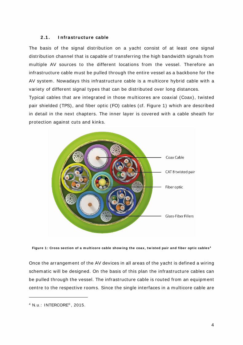
Typical cables that are integrated in those multicores are coaxial (Coax), twisted
pair shielded (TPS), and fiber optic (FO) cables (cf. Figure 1) which are described
in detail in the next chapters. The inner layer is covered with a cable sheath for
protection against cuts and kinks.
Figure 1: Cross section of a multicore cable showing the coax, twisted pair and fiber optic cables4
Once the arrangement of the AV devices in all areas of the yacht is defined a wiring
schematic will be designed. On the basis of this plan the infrastructure cables can
be pulled through the vessel. The infrastructure cable is routed from an equipment
centre to the respective rooms. Since the single interfaces in a multicore cable are
4 N.u.: INTERCORE®, 2015.

5
not assembled, the termination needs to be done at the respective technical spaces
and at the locations the AV sinks are based. Therefore a distribution box is
mounted at every equipment centre and sink location where the infrastructure
cable can be terminated. For spaces who only require a central distribution feed
and network connectivity, a pure FO cable run is sufficient.
All central distributed sources are consolidated in one or more main equipment
centres (MEC) or branch equipment centres (BEC). The MECs are usually based at
the lower decks of a vessel because of the lack of space for technical equipment
at the areas where guests or the owner is staying. Therefore the MECs are the
largest locations for AV equipment where most of the hardware is stored. The BECs
are branches of the MECs and are located nearer to the areas where the actual
signals are routed to. BECs are usually just to be found at yachts with a complex
AV system with a large amount of components. Through the BECs the AV/IT
system can be subdivided in smaller affiliations, like the allocation of one deck or
area to one equipment centre.
The local equipment centres (LEC) are based close to the spaces where the signal
is routed to. Typical locations where LECs are used are guest or owner cabins with
a great number of local AV equipment for which it is likely that they need to be
accessed often or a signal extension from a remote location is not desired. Typical
devices that are stores in LECs are disc players, AV receivers or processors.
Figure 2 shows the different possibilities of distributing the AV sources through
central locations like MECs and BECs, local distribution through LECs and the
combination of those three kinds of equipment centres.

6
Figure 2: Hardware distribution levels based on three different kinds of equipment centres
On most private luxury yachts the combination of the first and third distribution
level with one central MEC and small LECs in guest and owner cabins are most
common however, locations with a huge amount of AV hardware like cinemas and
event areas will still have their own technical spaces. The second distribution level
provides a better subdivision between different AV zones all over the vessel. The
sources and the distribution for each deck or area with special AV requirements
can be handled separately by moving them to BECs. In most cases those zones
got their own sub matrix but are still connected to the MEC where the main control
process is handled. The advantages of a second distribution level alongside the
shorter cable runs to the respective areas are a better maintainability through the
segmentation of the AV system into logic units for different areas.
2.1.1. Coaxial cable
Coaxial cables are built for high frequency signal transmission and are based on a
coaxial conductor construction. They are characterized by their length and
attenuation as the performance of the signal transmission decreases with the

7
distance and improves with a thicker conductor. Although the attenuation depends
on the frequency of the transmitted signal.
A coaxial cable consist of an inner conductor with a specific diameter 𝒅𝒅𝒊𝒊, an
overlying dielectric insulator with a dielectric constant ε and a relative permittivity
μ, a concentric outer cable with the diameter do, a shield out of metallic braid or
tape and the cable jacket (cf. Figure 3).
The main attribute of a coaxial cable is the characteristic impedance 𝑍𝑍0 and a
specific attenuation α. It is crucial that the impedance at the end of the cable
matches the characteristic impedance 𝑍𝑍0, otherwise reflections can occur which are
returning on the cable and distorting the signal.
Figure 3: Coaxial Cable Structure5
Typical applications for coax cables are broadband and baseband radio frequency
(RF) signal transmission where the signals needs to be protected against outside
interferences on long cable runs. The nominal impedance at electric circuits for low
voltage RF signal transmission is 75 Ω since it results in the lowest attenuation
through impedance matching when the isolator is air. In addition there are coax
cables with 30 Ω for a maximum power transmission and 50 Ω for communication
applications.6
5 N.u.: Typ-1-RG59-Kabel, 2015. 6 Cf. Schmidt, Ulrich: Professionelle Videotechnik, 2013, p. 63.
8
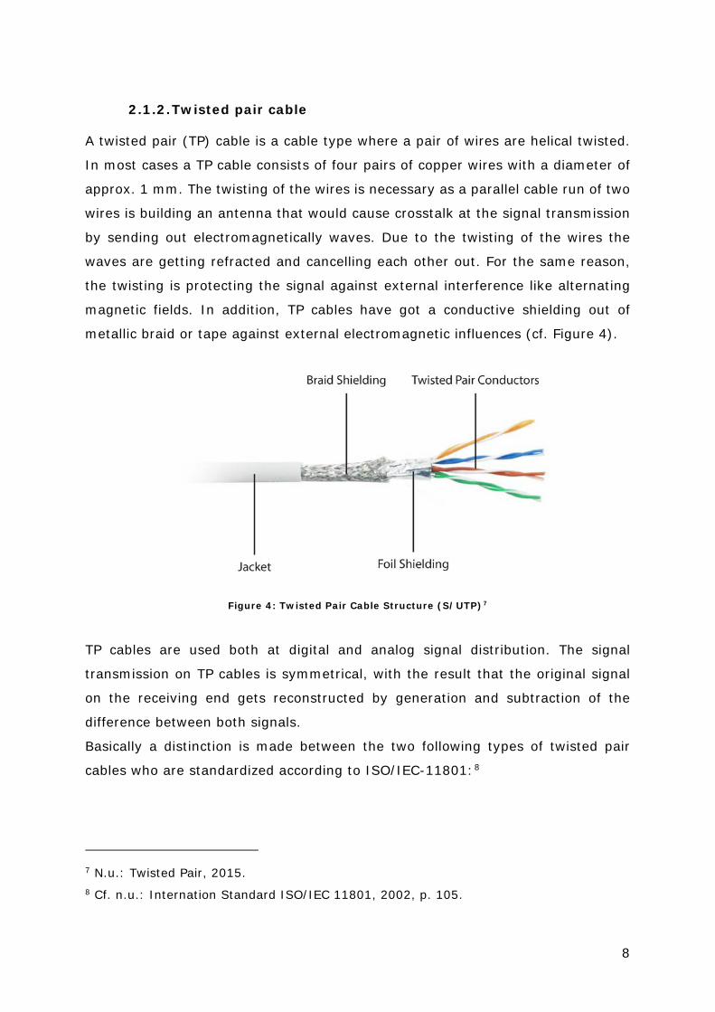
2.1.2. Twisted pair cable
A twisted pair (TP) cable is a cable type where a pair of wires are helical twisted.
In most cases a TP cable consists of four pairs of copper wires with a diameter of
approx. 1 mm. The twisting of the wires is necessary as a parallel cable run of two
wires is building an antenna that would cause crosstalk at the signal transmission
by sending out electromagnetically waves. Due to the twisting of the wires the
waves are getting refracted and cancelling each other out. For the same reason,
the twisting is protecting the signal against external interference like alternating
magnetic fields. In addition, TP cables have got a conductive shielding out of
metallic braid or tape against external electromagnetic influences (cf. Figure 4).
Figure 4: Twisted Pair Cable Structure (S/UTP)7
TP cables are used both at digital and analog signal distribution. The signal
transmission on TP cables is symmetrical, with the result that the original signal
on the receiving end gets reconstructed by generation and subtraction of the
difference between both signals.
Basically a distinction is made between the two following types of twisted pair
cables who are standardized according to ISO/IEC-11801:8
7 N.u.: Twisted Pair, 2015. 8 Cf. n.u.: Internation Standard ISO/IEC 11801, 2002, p. 105.
9
• Unscreened Twisted Pair (UTP)
Cable type with unshielded twisted pairs and without an overall shield.
Compared with shielded TP cables the maximum bandwidth and cable length
is far smaller. However, UTP cables can be used for Gigabit networks with
bandwidths up to 1 Ghz. The advantage over shielded cable types is the
smaller outer diameter that makes UTP cables easier to install. Although
UTP cables are less expensive as the shielded TP cables.
• Foil Screened Twisted Pair (FTP)
Cable type with a foil shield around each twisted pair but without an overall
screen. Due to the shielding the FTP cable have got a larger outer diameter
and the bending radius is a bit bigger, therefore FTP cables are more difficult
to install. However, the shielding provides a better protection against
external electromagnetic influences and crosstalk can be reduced.
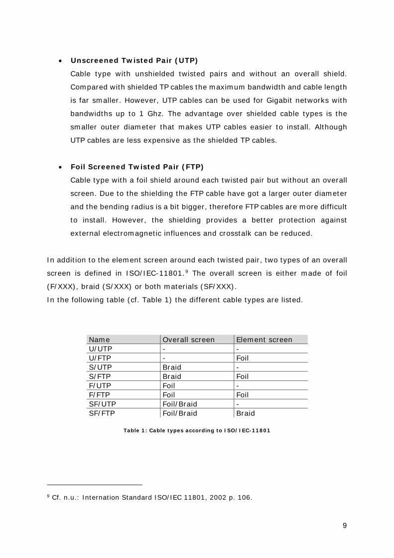
In addition to the element screen around each twisted pair, two types of an overall
screen is defined in ISO/IEC-11801.9 The overall screen is either made of foil
(F/XXX), braid (S/XXX) or both materials (SF/XXX).
In the following table (cf. Table 1) the different cable types are listed.
Name Overall screen Element screen U/UTP - - U/FTP - Foil S/UTP Braid - S/FTP Braid Foil F/UTP Foil - F/FTP Foil Foil SF/UTP Foil/Braid - SF/FTP Foil/Braid Braid
Table 1: Cable types according to ISO/IEC-11801
9 Cf. n.u.: Internation Standard ISO/IEC 11801, 2002 p. 106.
10
Furthermore TP cables are divided into seven cable categories (CAT) according to
their performance. Since the categories one to four are outdated due to their lack
of performance, the following explanations are related to the relevant TP
categories five to seven. However,
Table 2 shows the attributes of all specified TP categories. The most common
connector for TP cables is the RJ45 connector.10
• Category 5 (CAT5)
CAT5 cable are used for both voice and data transmissions with frequencies
up to 100 MHz. CAT5 cables are suitable for bitrates up to 100 Mbit/s
(100BASE-T). Of the four wire pairs only two pairs are used.
• Category 5e (CAT5e)
CAT5e (enhanced) cables are providing a better transmission characteristic
compared to CAT5 cables. By using all four wire pairs the bitrate can reach
up to 1000 Mbit/s (1000Base-T).
• Category 6 (CAT6)
With CAT6 cables the bandwidth increased from 100 MHz to 250 MHz.
However, the absolute bitrate of 1000 Mbit/s has not increased but as the
diameter of the conductors is bigger compared to CAT5e cables, the noise
immunity is higher and the attenuation lower. This leads to an extended
maximum cable length and a higher temperature range the cable can be
used.
• Category 6a (CAT6a)
CAT6a cables are increasing the maximum operating frequency up to
500 Mhz which results in a maximum bandwidth of 10 Gbp/s using all 4 wire
pairs. The greater frequency can be achieved through shielding (STP) and
thicker wire diameters, resulting reduced noise and crosstalk effects.
10 Cf. n.u.: RJ45-Stecker, 2015.

11
• Category 7/a (CAT7/a)
CAT7 cables are specified by a maximum frequency of 600 Mhz and is
realized through four individually shielded pairs and an overall shield (at
least S/FTP or F/FTP). Because of the high operating frequencies, a CAT7
infrastructure requires a new type of connector. The wires in a RJ45
connector are too close which leads to crosstalk at frequencies above 500
Mhz.11 Therefore the GG45 connector was developed and standardised in
2001 (IEC-60603-7-7). The GG45 connector adds four wires at the bottom
of the RJ45 layout whereby the distance between the conductors is
increased which leads to less crosstalk at high frequencies up to 1000 MHz
(CAT7a). The GG45 socket is backward compatible to RJ45 connectors by
detecting if the connector contains the four additional conductors. Because
of the different layout, the GG45 connector is not compatible to RJ45
sockets.
Table 2 shows the different performance characteristic of all released CAT cables
in the form of their maximum operating frequency and bandwidth.
Category Operating frequency Maximum bandwidth* CAT1 1 kHz 400 kbp/s CAT2 1 MHz 4 Mbp/s CAT3 16 Mhz 10 Mbp/s CAT4 20 Mhz 16 Mbp/s CAT5 100 MHz 100 Mbp/s CAT5e 100 MHz 1 Gbp/s CAT6 250 MHz 1 Gbp/s CAT6a 500 MHz 10 Gbp/s CAT7 600 MHz 10 Gbp/s CAT7a 1000 MHz 10 Gbp/s - 100 Gbp/s (Up to 15 m.) * For cable length < 100 m.
Table 2: Categories of twisted pair cables 12
11 Cf. n.u.: Twisted-Pair-Kabel, 2015. 12Cf. K., Rajesh: Network Cables, 2010.
12
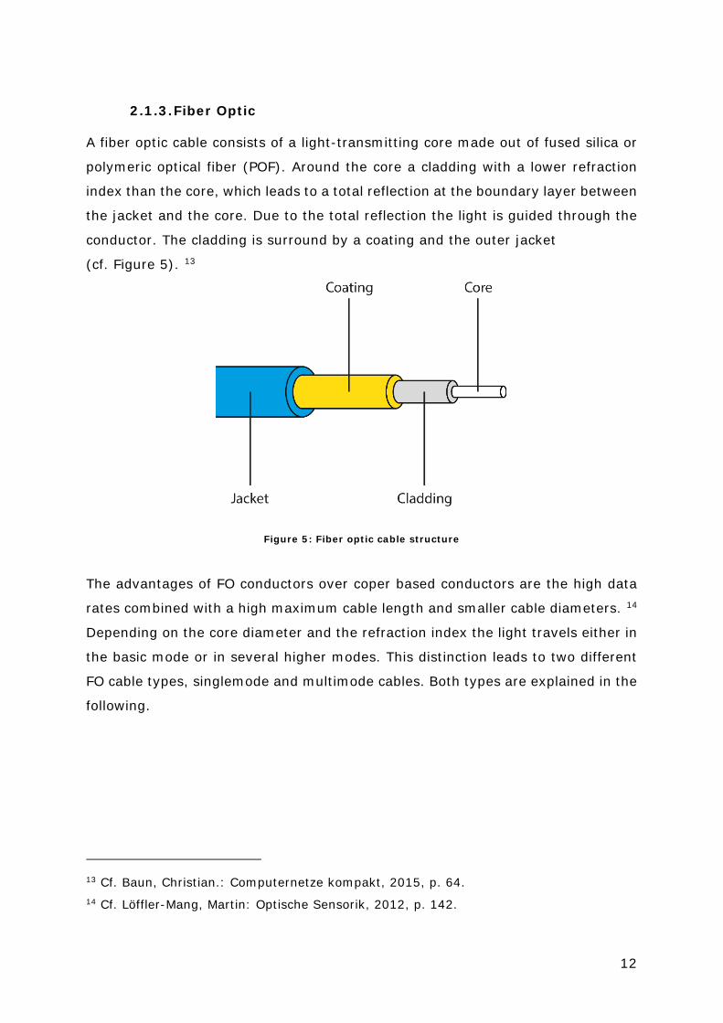
2.1.3. Fiber Optic
A fiber optic cable consists of a light-transmitting core made out of fused silica or
polymeric optical fiber (POF). Around the core a cladding with a lower refraction
index than the core, which leads to a total reflection at the boundary layer between
the jacket and the core. Due to the total reflection the light is guided through the
conductor. The cladding is surround by a coating and the outer jacket
(cf. Figure 5). 13
Figure 5: Fiber optic cable structure
The advantages of FO conductors over coper based conductors are the high data
rates combined with a high maximum cable length and smaller cable diameters. 14
Depending on the core diameter and the refraction index the light travels either in
the basic mode or in several higher modes. This distinction leads to two different
FO cable types, singlemode and multimode cables. Both types are explained in the
following.
13 Cf. Baun, Christian.: Computernetze kompakt, 2015, p. 64. 14 Cf. Löffler-Mang, Martin: Optische Sensorik, 2012, p. 142.
13
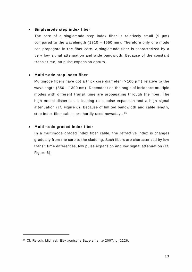
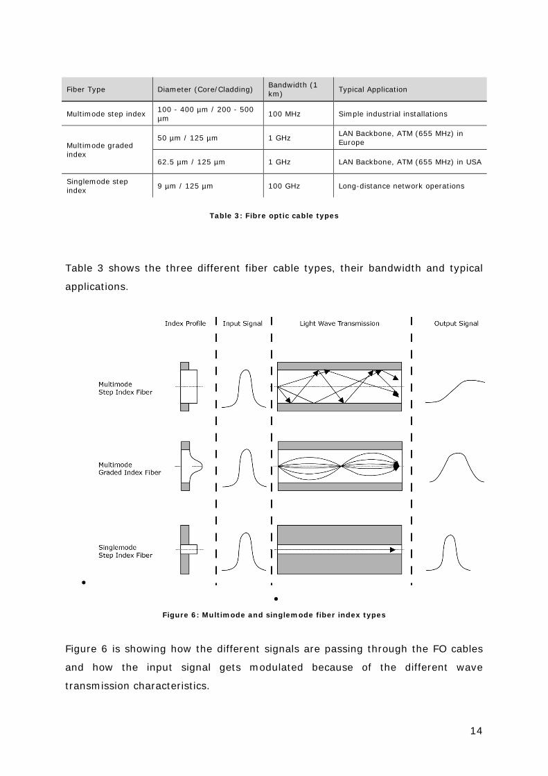
• Singlemode step index fiber
The core of a singlemode step index fiber is relatively small (9 µm)
compared to the wavelength (1310 – 1550 nm). Therefore only one mode
can propagate in the fiber core. A singlemode fiber is characterized by a
very low signal attenuation and wide bandwidth. Because of the constant
transit time, no pulse expansion occurs.
• Multimode step index fiber
Multimode fibers have got a thick core diameter (>100 µm) relative to the
wavelength (850 – 1300 nm). Dependent on the angle of incidence multiple
modes with different transit time are propagating through the fiber. The
high modal dispersion is leading to a pulse expansion and a high signal
attenuation (cf. Figure 6). Because of limited bandwidth and cable length,
step index fiber cables are hardly used nowadays.15
• Multimode graded index fiber
In a multimode graded index fiber cable, the refractive index is changes
gradually from the core to the cladding. Such fibers are characterized by low
transit time differences, low pulse expansion and low signal attenuation (cf.
Figure 6).
15 Cf. Reisch, Michael: Elektronische Bauelemente 2007, p. 1226.
14
Fiber Type Diameter (Core/Cladding) Bandwidth (1 km) Typical Application
Multimode step index 100 - 400 µm / 200 - 500 µm 100 MHz Simple industrial installations
Multimode graded index
50 µm / 125 µm 1 GHz LAN Backbone, ATM (655 MHz) in Europe
62.5 µm / 125 µm 1 GHz LAN Backbone, ATM (655 MHz) in USA
Singlemode step index 9 µm / 125 µm 100 GHz Long-distance network operations
Table 3: Fibre optic cable types
Table 3 shows the three different fiber cable types, their bandwidth and typical
applications.
• •
Figure 6: Multimode and singlemode fiber index types
Figure 6 is showing how the different signals are passing through the FO cables
and how the input signal gets modulated because of the different wave
transmission characteristics.
15
2.2. Local distribution
A first distinction of the different distribution systems on superyachts is drawn
between a local and a central distribution form. The local distribution is the
simplest way to allocate AV sources to different locations but although the least
flexible way. In a strict local distribution system every sink (e.g. display or
speaker) is connected directly to the respective sources and are located in the
same area. Therefore the devices can be connected directly via HDMI without the
need of signal extenders. This reduces costs and possible sources of error since
every additional device between the sink and the source can be damaged or drop
out. A local distribution although circumvents long cable runs through the ship
through Equipment that needs user interaction like connection panels, touch
panels, disc players and gaming consoles needs to be integrated locally to ensure
accessibility. Equipment in guest spaces that does not need to be accessed by the
guests is usually stored in a LEC (cf. chapter 2.1) in or near the room with adequate
service access. In an environment with just a few AV sources and sinks a local
distribution in most cases is cheaper and easier to realize than a central
distribution. As the AV system on luxury yachts are getting more and more
complex nowadays with a large number of different sources, a pure local
distribution is rarely applicable on recent luxury yachts. Only on small vessels
without sufficient space for a MEC to store AV devices centrally, a strict local
distribution would be applicable. Figure 7 shows the schematic of a local
distribution system, based on an exemplary guest cabin.

16
Figure 7: Local distribution schematic of an exemplary guest cabin
All sources (blue) are located in the cabin and are directly connected via HDMI to
the AV receiver which primary function is the switching of the different sources to
the display and secondary to amplify the speakers. The control processor takes
over the centralisation of the control of all sources so they can be controlled
through one control device instead of using one remote control for each source.
The control protocol depends on the sources connectivity but most of the current
AV sources can be controlled through the IP protocol. Further possible control
connections are RS232 and infrared (IR). An in-depth look to the functions of the
different AV devices on a yacht are given at chapter 3.
2.3. Central distribution
The second approach to distribute AV signals on a large scale yacht is through a
centralized system. This method is based on a central based core system which
joins all signals from the respective sources and distributes them to the single
locations. Those systems have got in common that they rely on one core device
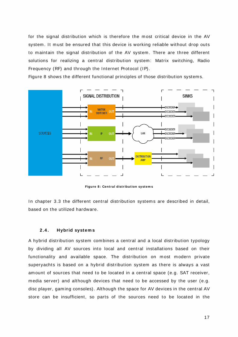
17
for the signal distribution which is therefore the most critical device in the AV
system. It must be ensured that this device is working reliable without drop outs
to maintain the signal distribution of the AV system. There are three different
solutions for realizing a central distribution system: Matrix switching, Radio
Frequency (RF) and through the Internet Protocol (IP).
Figure 8 shows the different functional principles of those distribution systems.
Figure 8: Central distribution systems
In chapter 3.3 the different central distribution systems are described in detail,
based on the utilized hardware.
2.4. Hybrid systems
A hybrid distribution system combines a central and a local distribution typology
by dividing all AV sources into local and central installations based on their
functionality and available space. The distribution on most modern private
superyachts is based on a hybrid distribution system as there is always a vast
amount of sources that need to be located in a central space (e.g. SAT receiver,
media server) and although devices that need to be accessed by the user (e.g.
disc player, gaming consoles). Although the space for AV devices in the central AV
store can be insufficient, so parts of the sources need to be located in the

18
respective cabins or areas. Another reason for a hybrid distribution system can be
the insufficient amount of inputs on the central AV matrix. Especially on AV refits
where new sources are added to the AV system but the AV matrix does not get
upgraded, the devices need to be integrated locally.
3. AV hardware on superyachts
As described in chapter 2 there are a lot of different AV devices used on modern
superyachts. On the one hand there is a vast number of different typical consumer
devices like TVs and media sources to measure up to the guest’s expectations of
a luxury accommodation. On the other hand the needed infrastructure for the
interconnection, distribution and control of those devices is based on professional
hardware. Therefore the challenge at the development and integration of an AV
system on superyachts is to design an environment where the user does not notice
the complex linkage of the single hardware modules and to create an infrastructure
that can be maintained by an ETO or a another crew member that is trained in AV
systems. In general the hardware can be divided in sinks, sources, distribution and
control. Depending on the approach of the distribution system those devices
besides the sinks can be placed central or local (cf. Figure 9).
Figure 9: Overview of AV hardware and their interconnection on a yacht
In a hybrid system (cf. chapter 2.4) there are two kinds of control systems. The
central control system takes over the control of the switching interface and the
central sources. The local controller is used for the remote controlling of the local

19
sources and sinks. The next chapters are outlining the different types of hardware
components that are typically used on private superyachts and pointing out the
challenges at the integration on a vessel. This roundup is also the basis for all
further considerations for the choice of hardware that have been installed in the
mobile training rack.
3.1. Sinks
The devices that are acting as a sink on a private superyacht can be divided in two
different classes, consumer and professional devices. Typical consumer devices
are flat screen displays, in-ceiling and in-wall loudspeakers, AV receivers and AV
processors and HiFi amplifiers. Those devices are mostly found in guest, owner
and crew cabins and although in lounge areas and representing the largest amount
of AV sink devices on a yacht. AV hardware that is built for the professional market
is mainly used in areas where special functionalities are required. Those locations
are for example external areas because of their weather exposure or locations
where a special audio and video experience is mandatory, like in private cinemas
and party areas.
The main reason behind utilising mainly consumer hardware is that the user on a
private yacht is demanding the same functionality of an AV entertainment system
as he is used to in residential buildings. Due to the short-lived media technology
nowadays it is although a question of costs and adaption of new features.
Especially display technologies are evolving fast since flat panel displays entered
the market and replaced cathode ray tube displays. Besides the continuously
increasing display resolutions (The ITU approved the 4k and 8k UHDTV resolutions
in 2012)16 the display panel technologies are evolving just as quickly. It is
therefore that alongside the increasing average display sizes new display
technologies like OLED17 and Quantum Dots18 are attracting the consumers’
16 Cf. n.u.: Recommendation ITU-R BT.2020-1, 2014, p. 2. 17 Cf. n.u.: OLED TVs, 2015. 18 Cf. Peach, Matthew: Quantum dots, 2015.
20
attention. As luxury yacht owners and guests are a target group who is demanding
the latest and greatest entertainment technology, displays are getting replaced
faster than most of the other AV sinks (e.g. loudspeakers and amplifiers).
However, professional devices are built to last longer than comparable consumer
devices and very often do not have the same features a user expects of an up-to-
date consumer device. Also professional AV devices are often much more
expensive than their consumer counterparts and the design more conservative
which does not fit often in extraordinary interior and exterior designs.
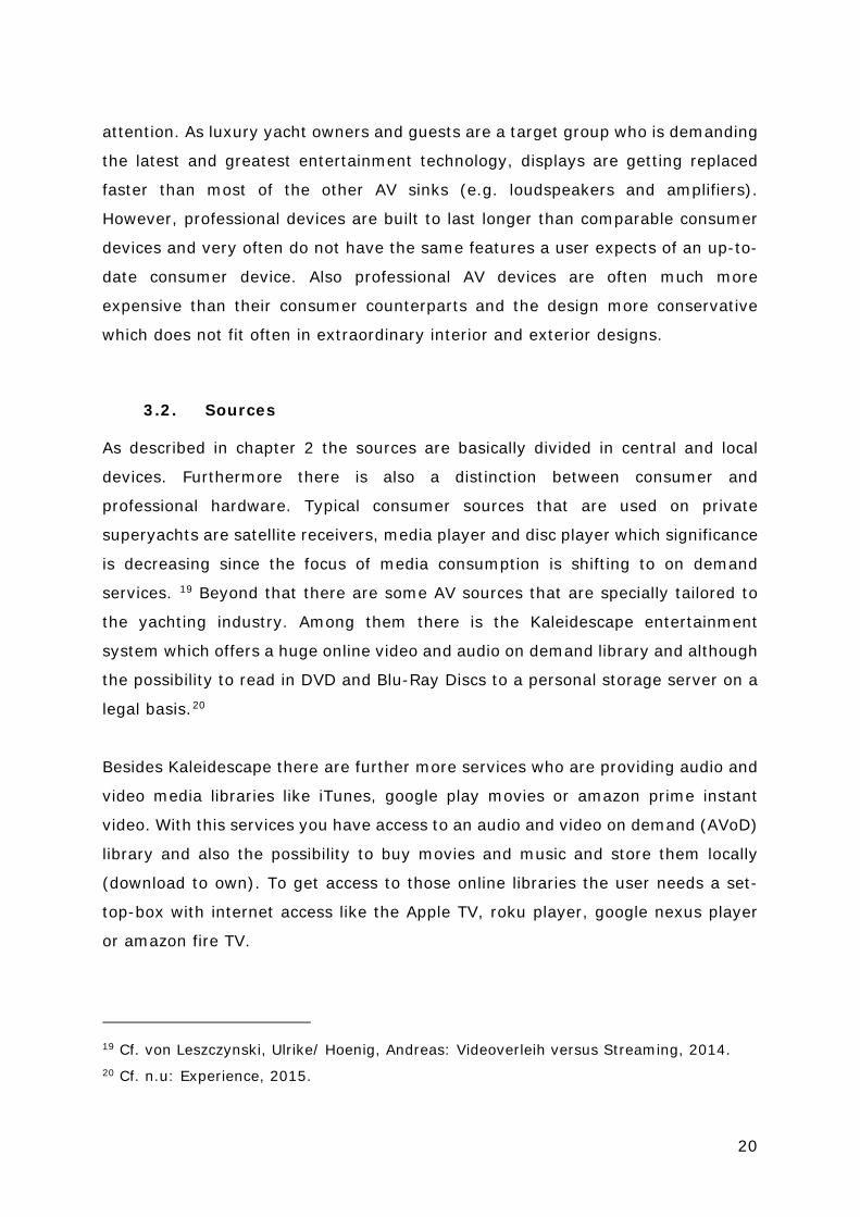
3.2. Sources
As described in chapter 2 the sources are basically divided in central and local
devices. Furthermore there is also a distinction between consumer and
professional hardware. Typical consumer sources that are used on private
superyachts are satellite receivers, media player and disc player which significance
is decreasing since the focus of media consumption is shifting to on demand
services. 19 Beyond that there are some AV sources that are specially tailored to
the yachting industry. Among them there is the Kaleidescape entertainment
system which offers a huge online video and audio on demand library and although
the possibility to read in DVD and Blu-Ray Discs to a personal storage server on a
legal basis.20
Besides Kaleidescape there are further more services who are providing audio and
video media libraries like iTunes, google play movies or amazon prime instant
video. With this services you have access to an audio and video on demand (AVoD)
library and also the possibility to buy movies and music and store them locally
(download to own). To get access to those online libraries the user needs a set-
top-box with internet access like the Apple TV, roku player, google nexus player
or amazon fire TV.
19 Cf. von Leszczynski, Ulrike/ Hoenig, Andreas: Videoverleih versus Streaming, 2014. 20 Cf. n.u: Experience, 2015.

21
Besides a local media library which can be used without an internet connection,
the access to satellite TV channels is a central requirement on the AV system on a
yacht as the users are used to those services on shore. However, satellite TV
services are not always available on a yacht because of different barriers like the
footprint of the actual satellites and the amount of simultaneous satellite services.
The footprint describes the reception area of a satellite signal on the global map
and depends on the orbit and size of the respective satellite.21
As each satellite service requires at least separate satellite dish, the amount of
simultaneous reception of different satellite services depends on the amount of
dedicated TVRO (Television receive online) satellite dishes.
Because of those reasons another niche technology evolved at the yacht industry.
Instead of receiving the satellite TV signals directly through the satellite decoders
on the yacht, the video signal of a decoder can be transmitted via an internet
stream. This technology is called IP TV and only requires a stable broadband
internet connection. As internet access on yachts is globally available through the
Ku, Ka and C band frequencies a stable internet connection can be achieved on a
yacht everywhere on the globe. 22 23 There are two relevant IP TV systems that
are used on private superyachts: Slingbox and Jetstream. Both services pursue
the approach to transmit the video signal of a sat decoder via an IP stream. The
Slingbox solution only offers the infrastructure for the IP stream, the decoder and
the streaming encoder needs to be provided by the user itself. Jetstream on the
other hand provides subscriptions which are including different satellite services
through data centres around the world which can be accessed through a
proprietary decoder box (Jetset) or via a web application. Those IP TV solutions
are providing TV reception independent from footprints, TVRO satellites and the
range of satellite decoders which are available on the yacht. Those services can
although be used as a fall-back solution if the regular satellite reception is not
available or to provide additional TV channels.
21 Cf. Wolff, Christian: Ausleuchtungszone, n.d.. 22 Cf. n.u.: C-Band, 2015. 23 Cf. n.u.: Fleet and coverage, 2015.)

22
The currently most demanded AV sources on vessels are providing access to AVoD
services and allow the integration of personal end user devices through local
streaming. The access to AVoD services like Netflix, Spotify, Youtube is increasing
since the last five years rapidly and will be the fastest growing sales market for
audio and video media.24 25 Therefore universal media player like the Apple TV and
the Roku Media Player have a high significance as local and central AV sources on
superyachts. Besides the access to AVoD services those devices are providing the
possibility for local streaming, the transmission of media from personal devices to
the central or local AV network through network services like Apple Airplay and
Miracast. The integration of those personal devices into an AV system is called
Bring Your Own Device (BYOD) and is facilitated through the mentioned media
players as a physical connection is not necessary.
When using online streaming services on yachts the internet connection is the
main limitation as on most vessels the available bandwidth is much lower as on
shore.26 This is because of the much higher costs for an internet connection
through satellite reception as the costs for the satellite infrastructure is just
financed by a few users compared to land based internet infrastructure where the
costs are divided across millions. Therefore a simultaneous access to online HD
video streams is only possible if the vessel has a great internet bandwidth (>10
Mbps) where monthly subscription costs can reach hundreds of thousands euro.
Because of the high costs for a great internet connection the bandwidth
management, which is regulating the available bandwidth for different network
devices, is an important task for the IT site on a yacht. Without a functioning
bandwidth management the AV devices with online services would exploit the
whole bandwidth as most of the consumer devices do not have a data limitation.
Because of the limited internet bandwidth, offline media libraries are still
mandatory on private superyachts.
24 Cf. n.u.: Musikstreaming-Abonnementdiensten, 2015. 25 Cf. Brandt, Mathias: Netflix, 2015. 26 Cf. Trask, Lulu: Connecting the dots, 2014.

23
The change of the media consumption, away from static (e.g. discs) and time-
dependent media (TV, radio) to on-demand services, affects the yachting industry
in the same manner as it does on the rest of the media landscape. The expectations
on the AV system in this luxury sector are high but they cannot always be fulfilled
as the internet connection is not as elaborated as onshore. Therefore a trade-off
between online and offline media sources needs to be found.
3.3. Distribution System
As described in chapter 2 there are a lot of different AV sources that need to be
distributed through the vessel. If the source and the sink are not located nearby
and are not connected through a point-to-point connection an infrastructure for
the distribution of the signals is needed. The main function of the distribution
system is to route the AV signals of the central sources to the respective remote
locations. As a basis for those distribution a communication channel based on RF,
TPS or FO (see chapter 2.3) needs to be provided.
Using RF for the signal distribution on superyachts is the longest-standing technic
and is based on the RF distribution in hotels. Here the output signals of the sources
are getting modulated on a RF carrier frequency. This is done on the basis of the
VHF frequency bands. Sources which do not provide RF signals as an output signal
(e.g. disc- and media player) the baseband signal needs to be modulated on the
RF carrier frequency. This is done by RF modulators which are adding the
modulated signals to the existing coax distribution system. This is done by RF
multiplexers which are combining different RF signals to one RF channel which is
based on DVB-C or DVB-T standard nowadays.
Figure 10 is showing a HDMI to RF QAM modulator with four HDMI inputs and
digital and analog audio inputs.

24
Figure 10: HDMI to RF modulator27
On the receiving end the signal gets decoded through the DVB-C or DVB-T tuner
of the TV. As most TVs got an integrated tuner this distribution variant takes no
additional distribution hardware (glue) at the location of the sink which safes
money and integration effort. The downside of a RF distribution is the limited
bandwidth so 4k cannot be distributed through RF and the determination on fixed
channels at the receiving end. Therefore a RF distribution is just being used for the
crew AV distribution as at those areas a cost efficient AV system is desired. This is
because the crew areas are representing a large part of the whole AV sinks, so
every saving on the hardware is multiplied quiet often.
Because of the limited bandwidth and the bounded modularity regarding the
integration and switching of new AV sources in a RF distribution, the usage of AV
matrix switcher have been established in the yacht AV sector.
An AV matrix switcher got the essential advantage of the free assignment of every
input to every output. Therefore it is possible to route all or just a selection of
sources to every sink on the vessel. Another advantage of an AV matrix is the
modular design of the switchers. The inputs and outputs (I/O) are implemented
through so called I/O-boards which are mounted in a matrix frame (cf.
Figure 11) and partitioned in one half inputs and one half output boards.
27 N.u.: HDb2840, 2015.

25
Figure 11: 32x32 Lightware matrix frame with various I/O boards28
The typical notation for the size of AV matrices is 32x32 for a matrix with 32 inputs
and 32 outputs. The common amount of inputs and outputs per board is 8 as this
segmentation can be found at all matrices from the leading manufactures like
Crestron, AMX, Lightware and PureLink.
The maximum amount of I/O boards depends on the frame, whereby matrices also
can be cascaded to one large-scaled logical matrix (cf. Figure 12).
Figure 12: Schematic of cascading AV matrices
I/O boards are available in big variety of interfaces. Typical input boards are:
HDMI, DVI, VGA, SDI, HDBaseT over TPS, FO, analog video over BNC, analog audio
over RCA. Output boards are available with HDMI, FO and TPS.
28 N.u.: 2015.
26
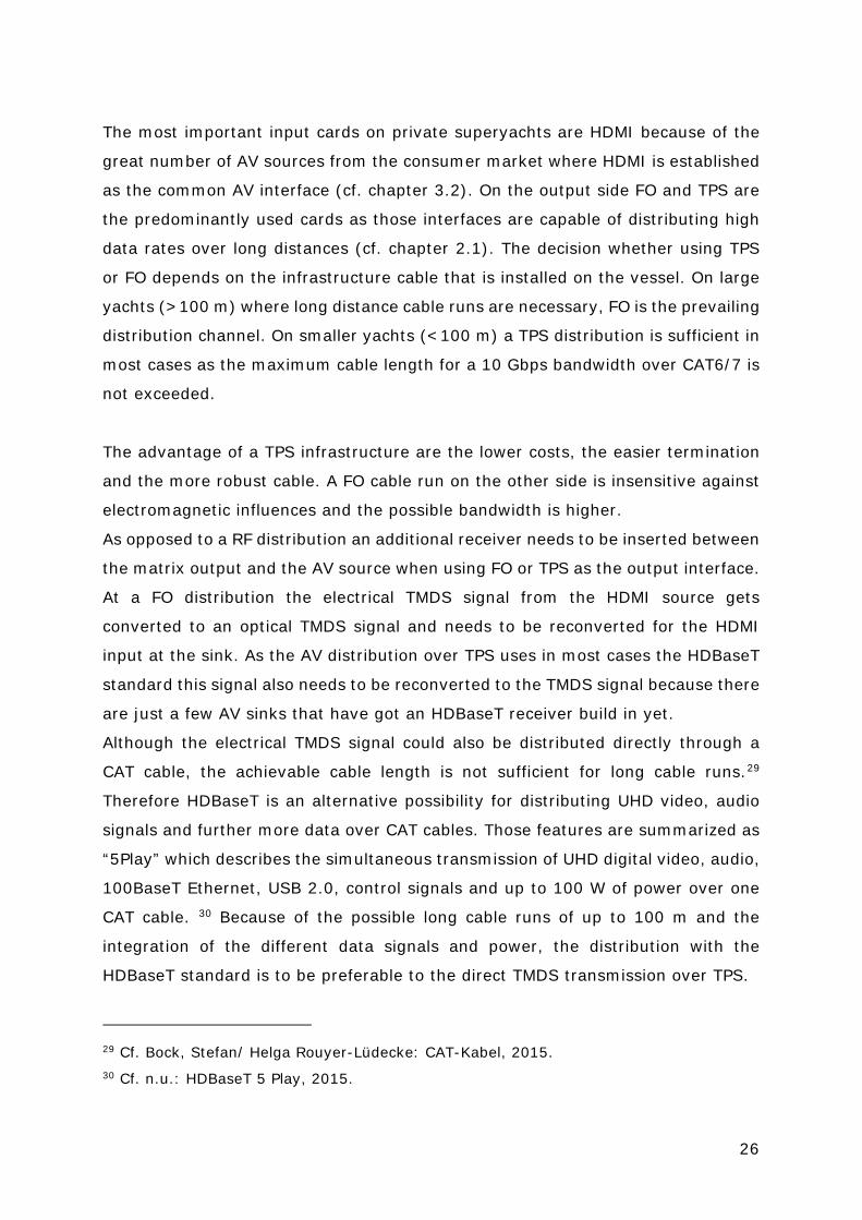
The most important input cards on private superyachts are HDMI because of the
great number of AV sources from the consumer market where HDMI is established
as the common AV interface (cf. chapter 3.2). On the output side FO and TPS are
the predominantly used cards as those interfaces are capable of distributing high
data rates over long distances (cf. chapter 2.1). The decision whether using TPS
or FO depends on the infrastructure cable that is installed on the vessel. On large
yachts (>100 m) where long distance cable runs are necessary, FO is the prevailing
distribution channel. On smaller yachts (<100 m) a TPS distribution is sufficient in
most cases as the maximum cable length for a 10 Gbps bandwidth over CAT6/7 is
not exceeded.
The advantage of a TPS infrastructure are the lower costs, the easier termination
and the more robust cable. A FO cable run on the other side is insensitive against
electromagnetic influences and the possible bandwidth is higher.
As opposed to a RF distribution an additional receiver needs to be inserted between
the matrix output and the AV source when using FO or TPS as the output interface.
At a FO distribution the electrical TMDS signal from the HDMI source gets
converted to an optical TMDS signal and needs to be reconverted for the HDMI
input at the sink. As the AV distribution over TPS uses in most cases the HDBaseT
standard this signal also needs to be reconverted to the TMDS signal because there
are just a few AV sinks that have got an HDBaseT receiver build in yet.
Although the electrical TMDS signal could also be distributed directly through a
CAT cable, the achievable cable length is not sufficient for long cable runs.29
Therefore HDBaseT is an alternative possibility for distributing UHD video, audio
signals and further more data over CAT cables. Those features are summarized as
“5Play” which describes the simultaneous transmission of UHD digital video, audio,
100BaseT Ethernet, USB 2.0, control signals and up to 100 W of power over one
CAT cable. 30 Because of the possible long cable runs of up to 100 m and the
integration of the different data signals and power, the distribution with the
HDBaseT standard is to be preferable to the direct TMDS transmission over TPS.
29 Cf. Bock, Stefan/ Helga Rouyer-Lüdecke: CAT-Kabel, 2015. 30 Cf. n.u.: HDBaseT 5 Play, 2015.

27
Therefore the matrix based distribution systems on superyachts are almost entirely
equipped with HDMI input cards and FO or HDBaseT over TPS output cards.
The amount of the I/O cards depends on two criteria. At first the amount of
independent AV locations which are requiring access to the central AV distribution.
The second criterion is the amount of central AV sources which in most cases is
determining the matrix size. Especially on vessels where no local AV sources shall
be used, the amount of central sources are scaling up the required inputs. That is
why on some superyachts matrices with 128 inputs and outputs are not
uncommon. The largest AV matrix available is made by PureLink with a size of
256x256. 31
Besides a signal distribution over an AV matrix which requires a separate cable run
for the AV infrastructure, HDMI over IP streaming solutions are gaining relevance.
The advantage over a RF or Matrix distribution is the simultaneous use of the CAT
infrastructure for IT and AV. But since the quality loss and the time delay through
compression is still adverse for a high quality AV distribution on yachts, the
technology needs to be further developed to be an actual alternative to the matrix
distribution.
3.4. Control Systems
Besides the advantages of the centralisation of AV sources through a central
distribution, like the saving of local space and the better maintenance, the direct
control of the sources at the sink is lost. With a local distribution the sources can
be controlled through a remote, but with the sources located in a MEC or BEC a
distinctive interface which enables a remote control over long distances is
necessary. Besides the control of the sources the distribution matrix also needs to
be controlled to switch the inputs to the corresponding outputs.
Therefore a control system is used on almost every modern superyacht which has
different interfaces to control all kinds of AV devices. The most widespread
manufacturers of control systems are Crestron and AMX. Both provide an
integrated hard- and software solution for remote controlling. The central device
31 Cf. n.u.: AV Matrix, 2015.

28
for a control system is a processor which provides the different control interfaces
like IR, RS-232, relays, analog and digital I/O ports and ethernet control shown in
Figure 13.
Figure 13: Rear view of a Crestron CP3 control processor with different control interfaces32
Most AV devices are providing different possibilities for remote control. The
decision which interface shall be used depends on the reliability and integration of
the interface. The preferred option, especially if the device is part of the local
network, is the control of ethernet, as no separate cable from the control processor
to the AV device is necessary. The next best solution is the control connection over
RS-232 as this is a physical end-to-end connection with simple serial command set
which is very resistant against errors. Whereas IR is the least preferable control
interface, although the control set is the same as RS-232, because of the optical
transmission through the atmosphere. The biggest problem with the IR connection
is the possible interference of the infrared signal through natural or artificial light.
Although the positioning and attachment of the IR diode to the respective device
can cause problems. The IR diodes may fall off or do not reach the IR receiver of
the device through wrong placement.
Besides the control processor as the back-end of the control system which handles
the command processing a front-end is necessary for the command input of the
user. There are different devices that can be used for the command prompt. At
the one side there are remote controls and keypads with free assignable hardware
buttons and on the other hand touchpads with a customized graphical user
interface (GUI). Some devices are shown in Figure 14.
32 N.u.: Crestron, 2015.

29
Figure 14: Control Devices: Crestron remote, keypad and Apple iPad with a Crestron GUI
In most cases the control through a touchpad is preferred as you can adjust the
interface to the needs and taste of the user.
A basic setup for controlling a hybrid AV system with central and local sources
consists of at least three different components:
1. A central processor to control the central sources and the matrix switcher.
2. A local processor to control the local sources and sinks as well as for the
linking of the control device.
3. A control device for the command prompt through the use.
The operation of a complex yacht AV system on a yacht is inconceivable without
such integrated control systems nowadays. In addition to the AV control the
system can also be used for controlling the lighting and HVAC (heating, ventilation,
air condition) of a yacht.
4. Conception and implementation of the training rack
In this chapter the development of the mobile training unit, which will be used for
the AV training, is described. The training concept, which was elaborated in
collaboration with the employees of Bond TM, serves as the basis for the design of
the training unit. As a first step the requirements on the hardware that will be used
are getting elaborated. The next step will be the device compilation and assembling
30
with a detailed review of the mounting and connection of the hardware. Finally,
the integration of the training unit at the first training course will be described.
4.1. Training Concept
The aim of the mobile training system was the content-related support of the AV
training course from Bond, by allowing the trainees to practice on a realistic yacht
AV system.
The AV training was developed because of the lack of trainings for AV technicians
on yachts. The target group of the training are engineers from yachts which do not
have an ETO so the engineers have to take over the tasks of an ETO. The training
is not qualifying ETOs but shall enable yacht crew members to perform basic
troubleshooting and a fundamental grasp for AV technology on board. For a deeper
insight to yacht AV system a second AV course shall be developed by Bond.
Precedent to the AV course an IT training was developed by Bond two years ago.
The IT training is being offered in two levels and is carried out two to three times
a year. At those trainings the trainees recurrently asked for the same training for
AV system so the idea for this training was born.
The IT training takes place at two days and on each day there is a theoretical and
a practical part where the trainees are practicing basic troubleshooting on IT
systems. Because of the positive feedback from the IT training the AV course shall
have a comparative concept. Therefore the requirements on the practical part of
the AV course was also the development of troubleshooting scenarios on actual AV
hardware.
The first day of the course comprises the AV basics audio, video and system design,
on the second day the control systems on yachts are handled. The AV learning
content is lectured by an employee of the Bond TM AV department, the second day
is led by A-Knowledge, subcontractor of Bond who have specialized in project
planning and programming of Crestron control systems. As the second day shall
also have a practical hands-on section the mobile training system needed to have
also complex control system hardware. The complete AV training concept is shown
in the appendix A.

31
Before the training concept was developed in detail the training unit was developed
to provide the right hardware for most of the topics that are covered at the
training. This procedure helped to create the content of the training around the
training unit, so that the hardware could be utilized in the most effective way.
4.2. Design of the training unit
The central function of the training unit is the demonstration of the theoretical
content as well as the implementation of troubleshooting tasks as the practical
part of the training. In addition the trainees shall get an insight into the latest AV
technologies which they might not have on the yachts where they work but might
be confronted with in the future on other yachts or at a refit.
As the training courses from Bond TM are taking place at the offices in Amsterdam
and Barcelona a crucial requirement was the transportability of the training unit.
The aim was to ensure that the training unit can be moved by two persons and is
fitting on a euro-pallet to easily transport the unit by a shipping company. Also the
unit needs to fit into the company car of Bond. Beside the size limitations another
requirement was the simple and quick build-up of the unit. The system should be
as much preconfigured as possible to reduce the installation time at the training.
This demand leads to the case that most of the hardware needed to fit in one
coherent unit.
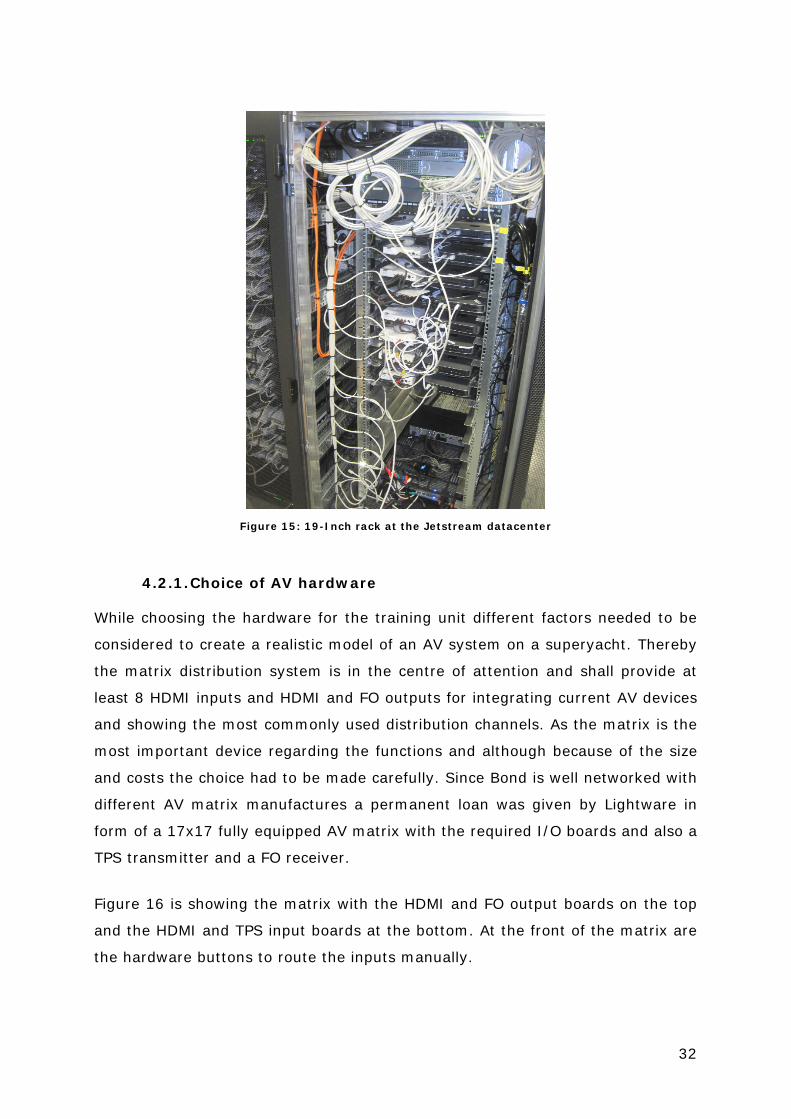
As the mounting of professional AV and IT hardware is normally realised through
19-inch racks (cf. Figure 15) and this mounting type is secure and established, as
many hardware as possible had to be integrated in a 19-inch rack. The selection
of the rack is describe in chapter 4.2.2 in detail.
32
Figure 15: 19-Inch rack at the Jetstream datacenter
4.2.1. Choice of AV hardware
While choosing the hardware for the training unit different factors needed to be
considered to create a realistic model of an AV system on a superyacht. Thereby
the matrix distribution system is in the centre of attention and shall provide at
least 8 HDMI inputs and HDMI and FO outputs for integrating current AV devices
and showing the most commonly used distribution channels. As the matrix is the
most important device regarding the functions and although because of the size
and costs the choice had to be made carefully. Since Bond is well networked with
different AV matrix manufactures a permanent loan was given by Lightware in
form of a 17x17 fully equipped AV matrix with the required I/O boards and also a
TPS transmitter and a FO receiver.
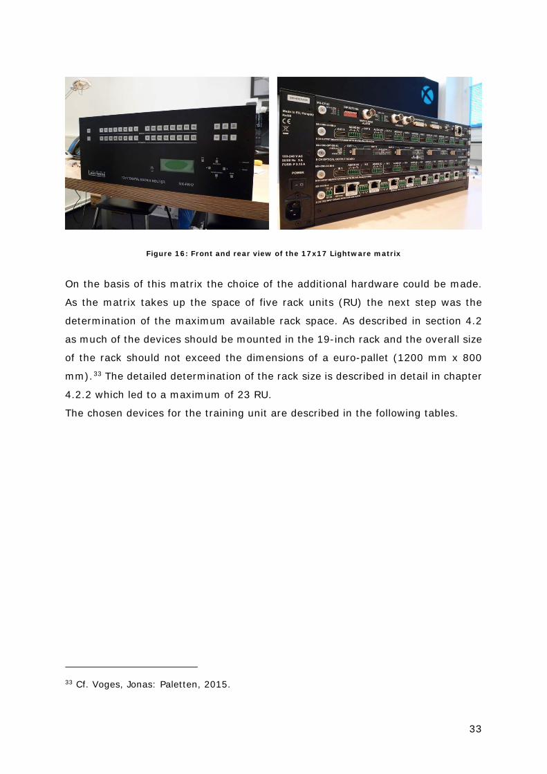
Figure 16 is showing the matrix with the HDMI and FO output boards on the top
and the HDMI and TPS input boards at the bottom. At the front of the matrix are
the hardware buttons to route the inputs manually.
33
Figure 16: Front and rear view of the 17x17 Lightware matrix
On the basis of this matrix the choice of the additional hardware could be made.
As the matrix takes up the space of five rack units (RU) the next step was the
determination of the maximum available rack space. As described in section 4.2
as much of the devices should be mounted in the 19-inch rack and the overall size
of the rack should not exceed the dimensions of a euro-pallet (1200 mm x 800
mm).33 The detailed determination of the rack size is described in detail in chapter
4.2.2 which led to a maximum of 23 RU.
The chosen devices for the training unit are described in the following tables.
33 Cf. Voges, Jonas: Paletten, 2015.

34
In-Rack hardwarePicture Device Description
Oppo BDP-103D
High-end Blu-Ray-Disc (BD) player with additional darbee chip for enhanced upscaling and conversion. Besides the playback of discs the player is also able to operate as a digital media renderer (DMR), the ability to play-back diverse media from network storage. Additional features: 4k upscaling and 2D to 3D conversion.
Apple TV
Set-Top-Box for play-back of AV media which is provided through the LAN or internet like music, podcasts, videos and movies. Futhermore the Apple TV gives access to a collection of online services like Youtube and diverse AV streaming services. Also the Apple TV can be used as a receiver for Airplay, Apples distinct interface for wireless media transfer.
Lightware MX-FR17
17x17 AV Matrix with 2 input and 2 free assignable I/O cards. Backplane with 12.8 Gbit bandwidth for 4k and 3D video signals. I/O boards:MX-HDMI-3D-OBA: HDMI input board 4k, 3D and deep colour compatible with analog audio stereo I/O.MX-TPS-IB-A: TPS input board for HDMI extension over HDBaseTMX-HDMI-3D-OBA: HDMI output board 4k, 3D and deep colour compatible with analog audio stereo I/O.MX-HDMI-OPT-OB-SC: HDMI 1.3 compatible FO output board with SC/SC connectors
Sony Playstation 4
Gaming console as an example for a typical local source because of the required local connection between concole and controller. The Playstation is also providing CD, DVD and BD playback and also access to a variety of streaming services.
Jetstream Jetset
Set-Top-Box for receiving the TV over IP stream, invented by bond. The Jetstream service and device is designed to be easily integrated into an AV system on yachts. The device is based on a small form factor PC with a proprietary operating system for the access and control of the Jetstream TV over IP service.
Marantz NR1605 Low profile 7.1 AV receiver with 8 HDMI inputs, 4k compatibility, WiFi, Bluetooth and Airplay streaming
Crestron CP3 Rack mountable control processor of the latest generation. Main control unit for the central sources and the matrix. Requested by A-Knowledge.
Crestron MC3 Small variant of the CP3 for use as a control unit for the local devices. Requested by A-Knowledge.
Cisco Catalyst 2950
24 port network switch for the IT infrastructure. Connects all network devices to the LAN and enables the control over ethernet by the crestron processor.
Apple AirPort Extreme Wireless LAN router to share the internet access over WLAN or LAN.
Table 4: In-Rack hardware description
35
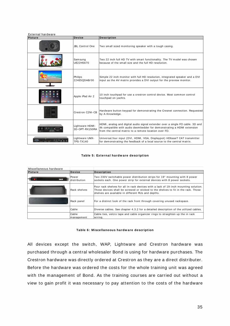
External hardwarePicture Device Description
JBL Control One Two small sized monitoring speaker with a tough casing.
Samsung UE22H5670
Two 22 inch full HD TV with smart functionality. The TV model was chosen because of the small size and the full HD resolution.
Philips 224E5QDAB/00
Simple 22 inch monitor with full HD resolution, integrated speaker and a DVI input as the AV matrix provides a DVI output for the preview monitor.
Apple iPad Air 2 10 inch touchpad for use a crestron control device. Most common control touchpad on yachts.
Crestron C2NI-CB Hardware button keypad for demonstrating the Cresnet connection. Requested by A-Knowledge.
Lightware HDMI-3D-OPT-RX150RA
HDMI, analog and digital audio signal extender over a single FO cable. 3D and 4k compatible with audio deembedder for demonstrating a HDMI extension from the central matrix to a remote location over FO.
Lightware UMX-TPS-TX140
Universal,four input (DVI, HDMI, VGA, Displaypot) HDbaseT CAT transmitter for demonstrating the feedback of a local source to the central matrix.
Table 5: External hardware description
Miscellaneous hardwarePicture Device Description
Power distribution
Two 230V switchable power distribution strips for 19" mounting with 8 power sockets each. One power strip for external devices with 8 power sockets.
Rack shelvesFour rack shelves for all in-rack devices with a lack of 19-inch mounting solution. Those devices shall be screwed or sticked to the shelves to fit in the rack. Those shelves are available in different RUs and depths.
Rack panel For a distinct look of the rack front through covering unused rackspace.
Cable Diverse cables. See chapter 4.3.2 for a detailed description of the utilized cables.
Cable management
Cable ties, velcro tape and cable organizer rings to straighten up the in rack wiring.
Table 6: Miscellaneous hardware description
All devices except the switch, WAP, Lightware and Crestron hardware was
purchased through a central wholesaler Bond is using for hardware purchases. The
Crestron hardware was directly ordered at Crestron as they are a direct distributer.
Before the hardware was ordered the costs for the whole training unit was agreed
with the management of Bond. As the training courses are carried out without a
view to gain profit it was necessary to pay attention to the costs of the hardware

36
and sometimes making compromises between functionality and exclusivity of the
devices.
For the calculation of the overall rack units, for the devices which have been
mounted in the rack, the diagramming application Microsoft Visio was used. With
the aid of the software the hardware and rack could be drafted by their actual
measurements. In this way the positionig of the devices in the rack could be tested
virtually to consider how the devices will be arranged and to include free rack units
for heat dissapation and maintenance.
Figure 17: AV rack allocation schematic
Figure 17 is showing the final rack allocation with the actual needed RU for the
hardware and free RU for heat dissapation and maintenance. The overall rack
height was estimated by this point as the exact model of the rack was not defined
yet.
The specification and choice of the mobile rack is described in the following
chapter.
4.2.2. Mobile rack
A central requirement on the training unit was the mobility of the whole hardware
setup (cf. chapter 4.2). This implies that all the devices are housed in portable

37
casings and still fitting on a euro-palett for easy shipping. Therefore the optimal
housing for the AV devices are 19-inch rack frames which typically are used at
datacenters and for event technology. The 19 inch are refering thereby to the
standardized width of the frame. The height of the 19-inch racks are indicated as
rack units (RU). One RU measures 1.75 inch.The hardware is getting mounted
through vertically aligned perforated rail for screw fastening with a gap of 1.25
inch in between (cf. Figure 18).
Figure 18: Rack frame dimensions
Besides the height the depth of rack frames are varying to fit the frame to the
depth of the devices that will be mounted in the rack. Common rack sizes are 42
RU (full height) and 18-22 RU (half height) with depths between 600 and 1000
mm.34
The rack for the mobile training unit should be equipped with the maximum RU
possible that still fits on the euro-pallet (1200 mm x 900 mm). In a length of 1200
mm 26 RU (approx. 1160 mm) would fit, but it needed to be considered that the
framework and casing of the rack itself will take away some space.
For transportable 19-inch racks the installation in a flightcase is a well tried and
tested option that protects the hardware from damage. Flightcases are shipping
34 Cf. n.u.: Define: EIA-310, 2007.

38
containers constructed out of 5 -20 mm thick plywood which is joined with
aluminium profiles and protected through rounded case corners. For the mobile
use those cases are fitted with 100 mm swivel castors and carrying handles. Those
parts of the superstructure of the case will reduce the available height for the
actual rack units.
After consultation of employees from Bond regarding a manufacturer for custom
made flightcases the company Amptown Cases were recommended because of
their well build and robust products.
For the integration of 19-inch racks into a flightcase Amptown provides different
types of cases which are available in a wide range of heights and widths.
The preferable variants for the rack enclosure are double-door and case-in-case
constructions as shown in Figure 19.
Figure 19: Double-door and case-in-case flightcases from Amptown
In both variants 19-inch hardware can be integrated from both sides through rack
rails and although swivel castors are optionally available. As on the case-in-case
model two RU are not accessible because of the foundation and the removing of
the lid might be impractical because of the height, the double-door case was
chosen for the training rack. 35
Figure 20 shows the actual flightcase that was ordered after consultation with
Amptown.
35 Cf. n.u.: Case in case, 2011.

39
Figure 20: Custom double-door rack from Amptown
Additionally rack shelves, panels and flightcases for the TVs and supplies were
ordered. The additional flightcases were ordered at Thomann as they are offering
ready-made cases that fitted the purpose and were cheaper than custom made
solutions.
4.3. Assembling the training rack
Besides the hardware selection the integration of the single devices into a coherent
unit was a challenge at the creation of the AV training course.
Before the devices were assembled and configured a functional schematic was
drawn to illustrate the distribution concept of the rack. On the basis of this
schematic the logical organization and wiring of the single components could be
carried out. The schematic although shows the division of local and central devices.
The assembling of the rack is divided in three sections:
1. Device mounting
2. Wiring
3. Configuration and commissioning
The complete assembling of the rack was executed at the office of Bond TM in
Hamburg.

40
4.3.1. Device mounting
Before the hardware was mounted in rack the exact positioning of the devices in
the rack needed to be elaborated. The first factor that had to be considered was
the access to all devices and their connectors in the assembled rack. This is
necessary as in the training all cables might be interchanged by the trainees and
to give an overview of the wiring concept. Because of the different widths of the
devices (100 – 400 mm) it might occur that a large device covers a smaller device
that is mounted below. To prevent this incident the larger device needed to be
mounted below the smaller devices or some free rack units needed to be assigned
above the small devices.
A second consideration should be made regarding the weight of the devices. To
prevent the rack from falling over easily the heavy devices should be mounted in
the lower sections of the rack. If the center of gravity is located on the lower half
of the rack, the rack will not fall over when moved careless.
Finally the devices should be mounted in order to keep the cable runs as short as
possible. For example by putting the AV matrix in the middle of the rack as this is
the device with the most cable connections. By keeping the cable runs short less
space is needed for the cable management and leads to a cleaner look of the rack.
Considering this three factors the rack allocation shown in Figure 17 has been
chosen.
The mounting of the hardware in the rack can be done in two ways. At first all
devices with an existing fastening possibility for 19-inch racks can be mounted
directly into the rack. Those devices providing drill holes in the front plate and the
width corresponds with the 19 inch of the rack. The following devices are having
actually 19-inch mounting possibilities:
• Switch: Cisco Catalyst 2950
• Control Processor: Crestron CP3
• AV matrix: Lightware MX-FR17
• Set-Top-Box: Jetstream Jetset
• Disc Player: Oppo BDP-103D
41
For the rest of the devices a different mounting solution for the secure integration
to the rack needed to be found. Therefore rack shelves are a flexible solution to fit
incompatible hardware into a 19 inch rack. Those shelves are frameworks with 19
inch rack dimensions where smaller devices can be fixed through screws, cable
ties or Velcro tape. Those shelves are available in different depths, rack units and
mounting possibilities. The following devices were mounted through shelves:
• Control processor: Crestron MC3
• Set-Top-Box: Apple TV
• Wireless access point: Apple Airport Extreme
• Game console: Sony Playstation 4
• AV receiver: Marantz NR1605
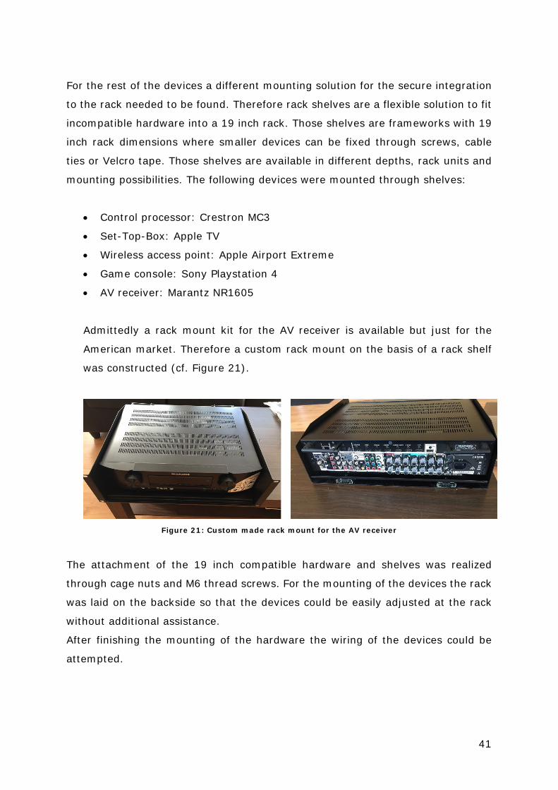
Admittedly a rack mount kit for the AV receiver is available but just for the
American market. Therefore a custom rack mount on the basis of a rack shelf
was constructed (cf. Figure 21).
Figure 21: Custom made rack mount for the AV receiver
The attachment of the 19 inch compatible hardware and shelves was realized
through cage nuts and M6 thread screws. For the mounting of the devices the rack
was laid on the backside so that the devices could be easily adjusted at the rack
without additional assistance.
After finishing the mounting of the hardware the wiring of the devices could be
attempted.

42
4.3.2. Wiring
The cabling of the devices can be divided in two categories. At first the power cable
distribution was carried out and afterwards the AV, IT and control wiring.
The power distribution is distinguishing from the rest of the cabling as those cables
will not be discussed or modified at the training. Therefore the connections can be
fitted inaccessible and hidden which is providing a cleaner look of the rack. As
shown in chapter 4.2.1 the power distribution is based on two power strips with
eight power sockets each on the top and bottom of the rack. The sockets are facing
into the rack to provide a clean look. Before the final cable management was
approached all devices were tested with loose cabling to test if a device is damaged
(cf. Figure 22).
Figure 22: Testing the hardware with lose cabling
The challenge with the wiring of the power cables was the tidied up placement as
the three-pole cables are thick (approx. 6 mm) and inflexible.
To keep the cables as short as possible to allow a hidden installation the cables
needed to be shortened to the ideal length. Therefore the cables were cut and
equipped with new connectors. In addition the external power supplies were fixed

43
discreet at the inside of the rack. Figure 23 is showing a shortened power cable
and with Velcro tape attached power supplies.
Figure 23: Attached power supplies and shortened power cords
After finishing the power cabling the connections for the AV, IT and control devices
were implemented. As a first step a cable plan was created which points out all
required connections. Based on this and the distances between the single devices
in the rack the different cable types were ordered. For every cable type at least
one spare was ordered to demonstrate faulty cables at the training and for
providing spares. The HDMI cable where provided complimentary from the
company PureLink.
To achieve a well structured wiring and a better distinction the AV and IT cables
were assigned to the left (IT) and right (AV) side of the rack. The cables were
conducted through rack organizer rings and bundled with Velcro cable ties. Those
measures are leading to a clean and well-structured cable management as shown
in Figure 24.
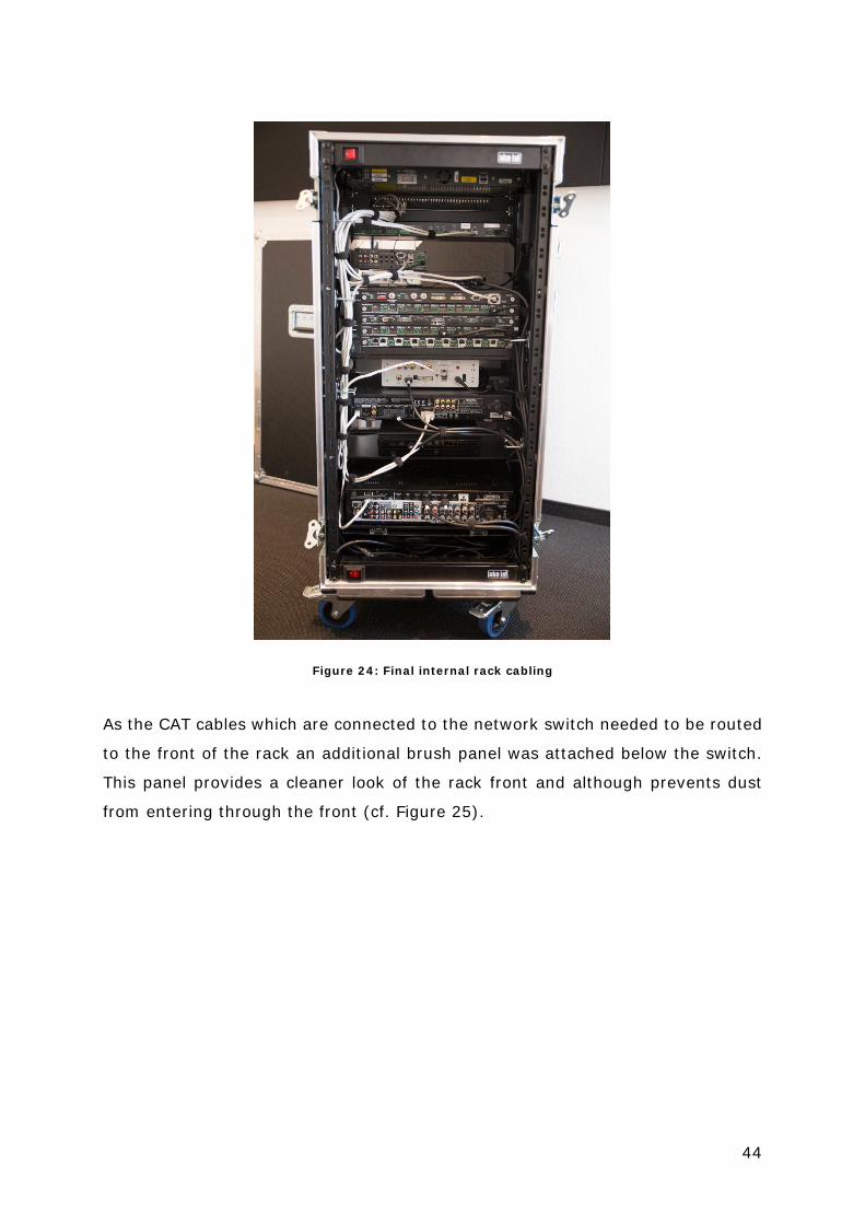
44
Figure 24: Final internal rack cabling
As the CAT cables which are connected to the network switch needed to be routed
to the front of the rack an additional brush panel was attached below the switch.
This panel provides a cleaner look of the rack front and although prevents dust
from entering through the front (cf. Figure 25).

45
Figure 25: Front view of the final training rack
Besides the internal rack cabling all external devices like the TVs, preview monitor,
transmitter, receiver, loudspeaker and keypad were connected according to the
wiring schematic (Appendix B) and although bundled through Velcro tape. After all
devices were connected the whole training setup was checked for connection
faults.
Alongside the cable management, the labelling and documentation of the
connection is a crucial part of the rack build. For labelling the cables typically self-
laminating labels were used which containing at least the following information:
Continuous cable number, cable type, start and end device on the opposite end of
the cable. In this way it is ensured that also third parties can track the cable-
routing.
After finishing the labelling a cable plan was created which is written in the same
way as the cables are labelled. The cable plan is shown in the appendix C. By the
use of the wiring schematic, cable list and cable labels the trainees can reconstruct

46
the cable routing which is a basis for the troubleshooting part on the training (cf.
chapter 4.4).
4.3.3. Configuration and functional overview
After finishing the hardware related work on the rack the single devices of the
training unit needed to be configured. This includes the IP address assignment, AV
device settings and the programming of the Crestron controller.
Starting with the IP address assignment it needed to be decided whether a static
or dynamic allocation through DHCP is chosen. An automated assignment through
DHCP makes the most sense in networks with many network devices as the IP
addresses do not have to be assigned manually. Because the training setup has
just a few and consistent devices, a static IP assignment should be preferred. This
allows an easier access to the device since the IP address is not changing.36
For the documentation the following logic for the IP assignment was chosen:
• 10.0.70.x: Network backbone
• 10.0.70.15x: Control devices
• 10.0.70.16x: Distribution system
• 10.0.70.17x: Central AV devices
• 10.0.70.18x: Local AV devices
The complete IP table is shown in appendix D.
At the configuration of the AV matrix the input and outputs where configured
through the Lightware device control software.
Apart from that, the matrix was configured in a way that the signal transmission
is realised transparent, means that the sinks are receiving the unbiased signal
from the source.
At all other AV devices only a few configurations had to be made as through the
EDID exchange the right settings are getting automatically negotiated by the
devices.37 However, the following configurations have been made:
36 Cf. n.u.: IP Adresses, 2015. 37 Cf. n.u.: Understanding EDID, 2009.
47
• IP assignment based on the IP table
• User setup for the Apple TV, Jetset and Playstation 4
• Loudspeaker configuration at the AV receiver
After finishing the device configurations, employees of A-Knowledge took over the
programming of the Crestron hardware. The demanded functions of the control
system were agreed with Bond in advance.
4.4. Development of troubleshooting scenarios
The primary function of the rack at the AV training should be the provision of an
environment where the trainees can gain hands-on experience (cf. Chapter 4.1).
Therefore different errors should be integrated into the training unit which the
trainees shall fix during the training course. Hereby the requirements on those
errors are:
• A fast implementation of the failure in the training unit in under five minutes
• Realistic errors that could occur on yachts
• Not too complex and solvable in under 15 minutes
• Integration of all devices of the training unit
At the development of the troubleshooting cases a lot of scenarios failed after
testing their practicability with some employees from Bond because they were
either too complicated or too simple to solve. After picking out the inconvenient
scenarios the tasks were classified in to three different difficulty levels to adjust
those to the individual skills of the trainees during the training course. Although
the trainees were allowed to use the following tools to fix the failure: Spare cables,
factory remotes, documentation of the training rack.
Table 7 shows the troubleshooting scenarios that were developed for the first
training course.

48
Scenario Error Cause LevelAfter a refit that included an upgrade of the AV system you are in charge of performing a pre-charter check one day before the first guest trip will take place.
Instead of the Blu-ray disc player we see Apple TV when trying to watch a Blu-ray disc
Input 6 and 7 are switched
1
The yacht owner is upset because he cannot watch a Blu-ray disc at the main salon
Blu-ray player is not working at the main Salon
FO cable between matrix and FO receiver is broken/not connected
1
A guest is complaining that he cannot stream movies from his iPad to the TV. He mentions that he just can hear the sound of the movie.
When streaming a video to the Apple TV the video is not displayed at the TV but audio is working
Broken HDMI cable between AVR and TV
1
The owner wants to watch a football game at the main salon. The game starts in 10 minutes and he dont get a picture.
Jetset input is not working at the main salon
Powerconnector from the Jetset PSU is not plugged in correctly
2
A movie night is planned at the main salon. Check if everything is working correctly
Instead of a widescreen picture the movie is played with a 4:3 aspect ratio
The aspect ratio from the TV is set up wrong
2
A guest wants to stream music from his iPad to his cabin but did not get any sound
No sound at the guest cabin The speaker connection at the AVR is loose
2
A guest is complaining that he did not get any sound from the game console
No sound from the Playstation
The audio format of the Playstation is not matching with the input configuration of the AVR
3
A guest is complaining that the sound is lousy while watching a Blu-ray disc
Dialogs are missing when playing a Blu-ray disc
EDID mismatch on the matrix. The Blu-ray player gets the EDID from the AVR and sends out multi channel audio
3
Table 7: Troubleshooting scenarios for the AV training
4.5. The final training course
After the finalization of the training unit and the content of the training a week
before the first training course a test setup was built at the office from Bond in
Amsterdam were the final training course also took place. At this stage the
functionality of the rack was tested and the cabling and configuration optimized.
The actual training took place on 3 and 4 June 2015 and was attended by six
trainees. Figure 26 shows the setup of the training unit at the first AV course in
Amsterdam.

49
Figure 26: Setup at the first training course at the Bond office in Amsterdam
During the lecture of the theoretical basics the trainer could always refer to the
single rack components and their functionalities to enhance the content with
practical examples. In the afternoon of both days the training unit was extensively
used for the hands-on troubleshooting scenarios.
Before the single tasks were assigned the system was explained by the wiring
schematics and the basic functionalities were shown. For the troubleshooting
exercises one trainee left the room and the fault was implemented and explained
in front of the other trainees. The trainee who has left the room was given a brief
explanation of the error (cf. Table 7) afterwards. At the troubleshooting the trainee
should look for the source of error by following the wiring and functional
schematics (Appendix E) and test each device in the relevant signal chain. The
proper way to approach fault finding was taught at the lecture before. If the
troubleshooting took too much time the other trainees were allowed to help or
little hints were given by the trainer. At the end of the training the most
complicated fault was implemented in the training unit and all of the trainees
should find the solution for the error.

50
After the two days of training the trainees were asked for feedback. Thereby the
troubleshooting part was commended by all participants. After finishing the
training the trainees received a certificate which is accredited by the Professional
Yachting Association (PYA) as well as a handout of the training content.
5. Summary and outlook
The aim of this bachelor thesis was the development of a training unit which
demonstrates the complex AV systems on private superyachts through a mobile
hardware-based training unit.
In coordination with experts from the AV yachting industry an integrated system
based on hard- and software modules was specified for the usage in a basic AV
training course for yacht crew members.
The development of the training unit started with a schematic of the first proposed
devices for the rack at the end of November 2014. During the six month until the
first training course the system was tested and optimized in different phases of
the build. Because of the ongoing improvements a fully functional and effective
training tool could be used at the first AV training course held by Bond. The
feedback from the trainees acknowledged the application of the rack as a central
part of the training course.
Although the first usage of the training unit were successful some aspects of the
rack can be optimized. At first the cabling can be executed even better by reducing
the length of the CAT cables as for now prefabricated cables are used which are
not in the right length. Furthermore the single devices in the training rack shall be
discussed more in detail. By now just a few functionalities of the hardware are
exhausted. The differentiated usage of each device could also be extended at the
troubleshooting scenarios.
Because of the positive feedback regarding the training rack it also should be
considered to integrate the unit during the first parts of the training as currently
the theoretical input prevails the first half of the course.
Regarding the further development of the training unit it should be noted that Bond
is planning to realize a second AV training for advanced yacht crew members who
are specialized in AV systems. According to the level 2 IT training profound AV

51
knowledge for superyachts shall be mediated at this course. Whereas the target
group of the level 1 AV training are yacht crew members who are taking care of
the AV system besides other tasks the level 2 training shall be educational for full-
time ETOs. On this course the training unit shall be used still more frequent and
might be equipped with further devices.
52
References
Baun, Christian, 2015: [Computernetze kompakt], 3. Auflage, Berlin/ Heidelberg: Springer-Verlag, 2015
Löffler-Mang, Martin, 2012: [Optische Sensorik], Wiesbaden: Vieweg+Teubner
Verlag, 2012 N.u., 2002: [Internation Standard ISO/IEC 11801]: Information technology -
Generic cabling for customer premises, 2. Auflage, Switzerland: ISO/IEC Copyright Office, 2002
Reisch, Michael, 2007: [Elektronische Bauelemente], 2., vollständig neu
bearbeitete Auflage, Berlin/ Heidelberg: Springer-Verlag, 2007 Schmidt, Ulrich, 2013: [Professionelle Videotechnik], 6. Auflage, Berlin/
Heidelberg: Springer-Verlag, 2013

53
Web references
Bock, Stefan/ Helga Rouyer-Lüdecke, 2015: Digitale Übertragungstechnologien
von Audio- und Videosignalen: [Cat-Kabel] und HDBaseT, Köln: MM-Musik-Media-Verlag GmbH & Co. KG, URL: http://www.professional-system.de/basics/digitale-uebertragungstechnologien-von-audio-und-videosignalen (status: 18.08.2015, call: 21.08.2015)
Brandt, Mathias, 2015: Netflix ist weiter auf Wachstumskurs, Hamburg: Statista
GmbH, URL: http://de.statista.com/infografik/2951/anzahl-der-streaming-abonnenten-von-netflix-weltweit (status: 16.07.2015, call: 17.08.2015)
K., Rajesh, 2010: Know your Cat 5-6-7 Unshielded Twisted Pair (UTP) [Network
Cables], s.l.: excitingip.com, URL: http://www.excitingip.com/847/know-your at-5-6-7-unshielded-twisted-pair-utp-network-cables (status: 2011, call: 12.07.2015)
N.u, 2011: [Case in case], Seevetal: amptown cases GmbH, URL:
http://www.amptown-cases.de/?dir=prod&link=393&id=1&lang=de (status: 2011, call: 06.09.2015)
N.u, 2015: [Crestron], Rockleigh: Crestron Electronics, URL:
http://help.crestron.com/cds/symbols/Device_Library/Control_Systems/CP3.jpg (status: 2015, call: 06.08.2015)
N.u., 2015: [C-Band], KU-Band and KA-Band, Belgium: Satmarin, URL:
http://www.satmarin.com/c-band%20and%20ku-band.asp (status: 2015, call: 16.08.2015)
N.u., 2007: [Define: EIA-310], Greenville: Innovation First, Inc., URL:
https://www.server-racks.com/eia-310.html (status: 11.10.2007, call: 02.09.2015)
N.u., 2015: Dynamic Versus Static [IP Addresses], Batavia: Fermilab, URL:
http://www.fnal.gov/docs/pc/nt_at_fermilab/html/current/ntguide.b.html (status: 2015, call 10.09.2015)
N.u., 2015: [Fleet and coverage], Betzdorf: SES S.A., URL:
http://www.ses.com/fleet-coverage (status: 2015, call: 16.08.2015) N.u., 2015: [HDb2840], Boston/ Denver/ London: Zeevee. Inc., URL:
http://zeevee.com/products/hdbridge/hdb2840 (status: 2015, call: 21.08.2015)
N.u., 2015: [HDBaseT 5 Play]: What are the 5Play future set?, Tel Aviv: Beaver
Global Ltd URL: http://clients.beaverglobal.com/installers/lesson/hdbaset-5play (status: 2015, call: 21.08.2015)

54
N.u., 2015: [INTERCORE®] Multicore Hybrid Cable AVIT ONE, Berlin: panoiter, URL: http://www.panointer.com/index.php/2012-07-06-13-15-08 (status: 2015, call: 21.07.2015)
N.u., 2015: [Lightware], Hungary: Lightware Visual Engineering, URL:
http://www.lightware.eu/mxseries/images/mxseries/MX-FRAME.jpg (status: 2015, call: 12.07.2015)
N.u., 2015: [OLED TVs]: introduction and market status, Herzerlia: OLED-Info,
Metalgrass software, URL: http://www.oled-info.com/oled-tv (status: 2015, call: 06.08.2015)
N.u.: PRO-PM-256X - Frei bestückbare 256x256 [AV Matrix], Rheine: Purelink
GmbH, URL: http://www.purelink.de/professional/modulare-kreuzschienen-matrix/puremedia-serie/pro-pm-256x-256x256 (status: 2015, call: 21.08.2015)
N.u., 2015: [Running Long Cable Lengths], Sunnyvale: HDMI Licensing, LLC, URL:
http://www.hdmi.org/installers/longcablelengths.aspx (status: 2015, call: 09.07.2015)
N.u., 2015: [RJ45-Stecker], Peterskirchen: DATACOM Buchverlag GmbH, URL:
http://www.itwissen.info/definition/lexikon/RJ-45-Stecker-RJ-45-male-connector.html (status: 2015, call: 17.07.2015)
N.u., 2015: [Twisted-Pair-Kabel] Twisted-Pair-Kabel (UTP / FTP / STP),
Ludwigsburg: Elektronik-Kompendium.de, URL: http://www.elektronik-kompendium.de/sites/net/0603191.htm (status: 2015, call 18.07.2015)
N.u., 2015: [Typ-1-RG59-Kabel], Teheran: IMENDID, URL:
http://www.imendidnegin.com/?product=%DA%A9%D8%A7%D8%A8%D9%84-rg59 (status: 2015, call 18.07.2015)
N.u., 2009: [Understanding EDID] - Extended Display Identification Data, s.l.:
Extron Electronics, URL: http://www.extron.com/company/article.aspx?id=uedid (status: 2009, call: 12.09.2015)
N.u., 2015: Unshieded [Twisted Pair] CAT6 Cable, Jiangsu: Focus Technology Co.,
Ltd., URL: http://simpact.en.made-in-china.com/product/uXfnaKYlvohT/China-Unshieded-Twisted-Pair-CAT6-Cable.html, (status: 2015, call: 12.08.2015)
N.u., 2015: Zahlende Abonnenten von [Musikstreaming-Abonnementdiensten]
weltweit in den Jahren 2010 bis 2014 (in Millionen), Hamburg: Statista GmbH, URL:http://de.statista.com/statistik/daten/studie/297786/umfrage/abonnenten-von-musik-streaming-diensten-weltweit (status: 2015, call: 17.08.2015)

55
Peach, Matthew, 2015: [Quantum dots] are ‘ready for prime time’ says analyst, Cardiff: optics.org, http://optics.org/news/6/5/19 (status: 13.05.2015, call: 06.08.2015)
Somers, Steve, 2015: [DVI and HDMI]: The Short and the Long of It, s.l.: Extron
Electronics, http://www.extron.com/company/article.aspx?id=dvihdmi_ts (status: 2015, call: 09.07.2015)
Voges, Jonas, 2015: [Paletten], Böblingen: transportbranche.de, URL:
http://www.transportbranche.de/wissen/paletten (status 2015, call: 23.08.2015)
von Leszczynski, Ulrike/ Hoenig, Andreas, 2014: [Videoverleih versus Streaming]:
Tod auf Raten?, Berlin: Verlag Der Tagesspiegel GmbH, URL: http://www.satmarin.com/c-band%20and%20ku-band.asp (status: 16.10.2014., call: 16.08.2015)
Trask, Lulu, 2014: [Connecting the dots], London; TRP Magazines Ltd, URL:
http://www.thecrewreport.com/features/21870/connecting-the-dots (status: 20.08.2014, call: 17.08.2015)
Wolff, Christian, n.d.: Ausleuchtungszone, s.l.: cc-by-sa, URL:
http://www.radartutorial.eu/20.airborne/ab50.de.html (status: 2015, call: 16.08.2015)

56
Appendix A – Training syllabus

57
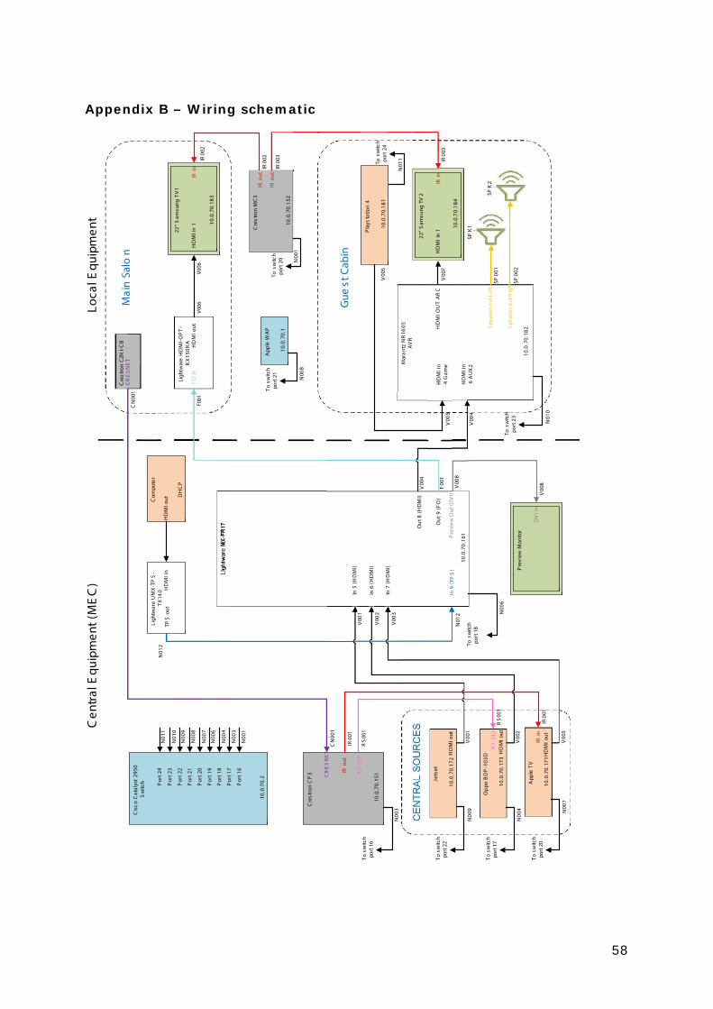
58
Appendix B – Wiring schematic
Cre
stro
nC
P3
Mar
ant
zN
R16
05A
VR
Mai
nSa
lon
Gue
st C
abin
Cis
coC
atal
yst
2950
Sw
itch
Op
poB
DP
-103
D
Jets
et
Cre
stro
nM
C3
App
leW
AP
App
leTV
Cre
stro
nC2
NI-C
B
Ligh
twar
eH
DM
I-O
PT
-R
X15
0RA
22"
Sam
sung
TV
1
22"
Sam
sung
TV2
In6
(HD
MI)
In5
(HD
MI)
In7
(HD
MI) Pre
view
Mon
itor
Pre
view
Out
(DV
I)
HD
MIO
UT
AR
C
In9
(TP
S)
HD
MIo
ut
HD
MIo
ut
HD
MIo
ut
HD
MIi
n6
AU
X2
Ou
t8(H
DM
I)
FOin
Out
9(F
O)
HD
MIi
n1
IRin
RS
232
IRou
t
RS
232
IRin
IRin
IRou
t
IRou
t
CR
ES
NE
T
CR
ES
NE
T
Por
t24
Por
t23
Por
t22
Por
t21
Por
t20
Por
t19
Por
t18
Por
t17
Por
t16
Tosw
itch
port
21
Tosw
itch
port
16
Tosw
itch
port
22
Tosw
itch
port
17
Tosw
itch
port
20
Tosw
itch
port
18
Tosw
itch
port
23
Tosw
itch
port
2010
.0.7
0.1
10.0
.70.
2
10.0
.70.
151
10.0
.70.
172
10.0
.70.
173
10.0
.70.
171
10.0
.70.
161
10.0
.70.
182
10.0
.70.
152
10.0
.70.
183
10.0
.70.
184
DV
Iin
tnempiuq
ElacoL)
CE
M(tnempiuq
ElartneC
Ligh
twar
eU
MX
-TP
S-
TX14
0C
ompu
ter
HD
MIo
utTP
Sou
tH
DM
Iin
DH
CP
Pla
ysta
tion
4
HD
MIo
ut
Tosw
itch
port
2410
.0.7
0.18
1
HD
MIi
n4
Gam
eH
DM
Iin
1
Spe
aker
out L
eft
Spe
aker
outR
ight
V00
1
V00
2
V00
3
V00
1
V00
2
V00
3
CN
001
CN
001
IR00
1
RS
001
IR00
1
RS
001
N00
1
N00
3
N00
4
N00
6
N00
7
N00
8
N00
9
N01
0
N01
1
N00
3
N00
9
N00
4 N00
7
N00
6
V00
8V00
8
F00
1
V00
4
V00
4
V00
5
V00
5
N01
1
N00
1
600V600V
100FIR
002
IR00
2
IR00
3
IR00
3
SP00
1
SP00
2
N00
8
N01
0
V00
7
N01
2
N01
2
SPK
1
SPK
2

59
Appendix C – Cable plan
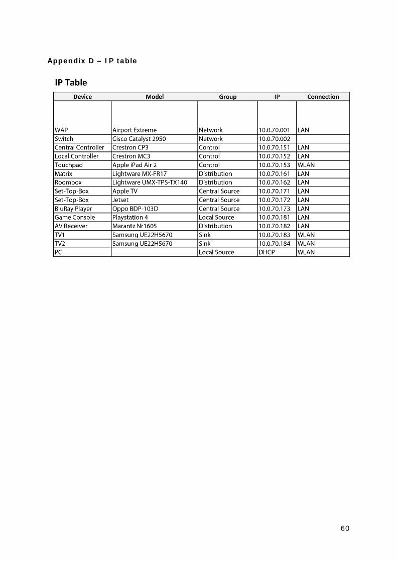
60
Appendix D – IP table
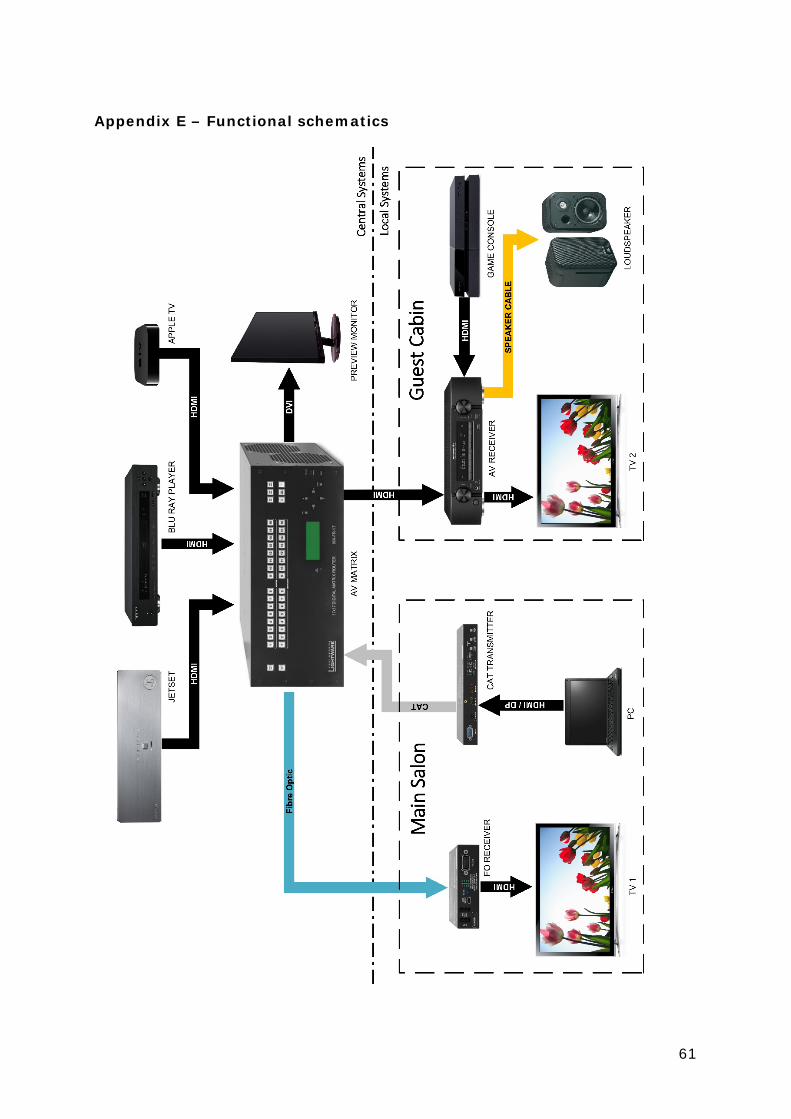
61
Appendix E – Functional schematics
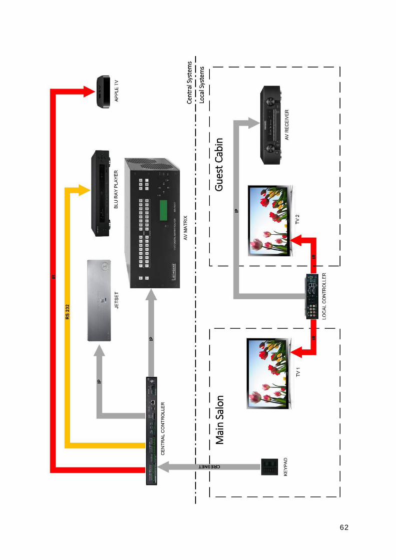
62

63
Statutory declaration I declare that I have authored this thesis independently, that I have not used other
than the declared sources/ resources, and that I have explicitly marked all material
which has been quoted either literally or by content from the used sources.
Hamburg, 21.09.2015 ………………………….. (Hannes Winkel)