Embed Size (px)
Citation preview

i
p
BACHELOR THESIS – (ME 141502) ANALYSIS OF MOORING SYSTEM DESIGN ON FLOATING PLATFORM OF OCEAN CURRENT POWER PLANT USING CFD (COMPUTATIONAL FLUID DYNAMICS) METHOD Muhamad Arif Budiman Rivai NRP. 4212101037 Supervisors: Irfan Syarif Arief, S.T, M.T Ir. Tony Bambang Musrijadi, PGD Marine Engineering Department Faculty of Marine Technology Institut Teknologi Sepuluh Nopember Surabaya 2016

ii
(This page intentionally left blank)
iii
SKRIPSI – (ME 141502)
ANALISA PERENCANAAN MOORING SYSTEM PADA FLOATING PLATFORM PEMBANGKIT LISTRIK TENAGA ARUS LAUT DENGAN MENGGUNAKAN METODE CFD (COMPUTATIONAL FLUID DYNAMICS)
Muhamad Arif Budiman Rivai NRP 4212101037 Dosen Pembimbing : Irfan Syarif Arief, S.T, M.T Ir. Tony Bambang Musrijadi, PGD
Jurusan Teknik Sistem Perkapalan Fakultas Teknologi Kelautan Institut Teknologi Sepuluh Nopember Surabaya 2016

iv
(This page intentionally left blank)
v

vi
(This page intentionally left blank)
vii
viii
ix
ANALYSIS OF MOORING SYSTEM DESIGN ON FLOATING PLATFORM OF OCEAN CURRENT POWER
PLANT USING CFD (COMPUTATIONAL FLUID DYNAMICS) METHOD
Name : Muhamad Arif Budiman Rivai NRP : 4212101037 Department : Marine Engineering Supervisor : 1. Irfan Syarif Arief, S.T, M.T 2. Ir. Tony Bambang Musrijadi, PGD
Abstract Floating platform of ocean current power plant requires good stability against sea waves, ocean currents, wind and other external force. Stability of Floating Platform is greatly influenced by the selection of mooring system. The precise selection of mooring system will reduce the degree of free movement (Surge, Sway, Heave, Pitch, Sway, and Roll) on Floating Platform. Degree of free movement can be observed by RAO and Spectrum response. Mooring system that are safe, strong, effective and economic must consider the number of line, line spacing, diameter of line, material of line, and the tension that can be hold. Selection of mooring systems that are safe, effective and economic are absolutely required in order to maintain the stability of Floating Platform so that all components of the equipment which are above Floating Platform can operates optimally.
Keywords : Floating platform , RAO, Spectrum Response

x
(This page intentionally left blank)
xi
ANALISA PERENCANAAN MOORING SYSTEM PADA FLOATING PLATFORM PEMBANGKIT
LISTRIK TENAGA ARUS LAUT DENGAN MENGGUNAKAN METODE CFD
(COMPUTATIONAL FLUID DYNAMICS)
Nama : Muhamad Arif Budiman Rivai NRP : 4212101037 Jurusan : Marine Engineering Dosen Pembimbing : 1. Irfan Syarif Arief, S.T, M.T 2. Ir. Tony Bambang Musrijadi, PGD
Abstrak
Floating platform pada pembangkit listrik tenaga arus laut membutuhkan stabilitas yang baik untuk melawan gelombang laut, arus laut, angin, serta gaya luar lainnya. Stabilitas dari Floating platform sangat dipengaruhi oleh mooring system yang dipilih. Mooring system yang tepat akan mengurangi derajat gerakan kebebasan (Surge, Sway, Heave, Pitch, Sway, dan Roll)
pada derajat gerakan kebebasan dapat dilihat melalui grafik RAO dan spectrum Response. Mooring System yang aman, effisien dan ekonomis harus mempertimbangkan jumlah line, jarak antar line, diameter line, material line, serta tension yang dapat ditahannya. Pemilihan mooring system yang aman, efektif dan ekonomis mutlak hukumnya agar menjaga stabilitas Floating platform sehinga semua komponen peralatan yang berada diatas Floating
platform dapat berkerja secara optimal.
Kata Kunci : Floating platform,RAO, Spectrum Response

xii
(This page intentionally left blank)

xiii
Preface Author praise Allah SWT the Almighty who has given the grace and guidance so that author can finish bachelor thesis report well and smoothly. The author would like to thank those who have helped the implementation of bachelor thesis report : 1. Allah SWT 2. My Parents who always support me. 3. Mr. Dr. Eng. M. Badrus Zaman, ST. MT. as Head of Marine Engineering Department 4. Mr. Semin ,ST ,MT ,Ph.D as in secretary of Marine Engineering Department 5. Irfan Syarif Arief, S.T., M.T. as my Bachelor Thesis Supervisor Lecturer 6. Ir. Tony Bambang Musrijadi, PGD as my Bachelor Thesis Supervisor Lecturer 7. My friend in Marine engineering department 8. All member at marine manufacturing and design laboratory 9. Everyone who help me in making the bachelor thesis The authors recognize that the preparation of the bachelor thesis Report may be a deficiency for readers. Thus the authors expect criticism and suggestions from readers for better report. The authors hope that this bachelor thesis can be useful to the reader.
Surabaya, 30 July 2016
M. Arif Budiman Rivai 4212 101 037

xiv
(This page intentionally left blank)
xv
Contents Approval Sheet ............................ Error! Bookmark not defined. Abstract ........................................................................................ ix
Abstrak ......................................................................................... xi Preface ........................................................................................xiii Contents ....................................................................................... xv
Figures ........................................................................................ xix
Tables ......................................................................................... xxi Chapter 1 ....................................................................................... 1
Introduction ................................................................................... 1
1.1 Background ......................................................................... 1
1.2 Problem Formulation and Scope ......................................... 2
1.3 Objective ............................................................................. 3
1.4 Benefit ................................................................................. 3 Chapter 2 ....................................................................................... 5
Literature Review .......................................................................... 5
2.1 Floating Platform Of Ocean Current Power Plant ............... 5
2.2 Environment Loads ............................................................. 6
2.2.1 Wind Force ................................................................... 6
2.2.2 Wave Force................................................................... 7
2.2.3 Current Force ................................................................ 7
2.3 Mooring Line ....................................................................... 8
2.3.1 Chain rope .................................................................... 8
2.3.2 Wire rope ...................................................................... 9
xvi
2.3.3 Synthetic Fibre rope ..................................................... 9
2.4 Mooring System ................................................................ 11
2.4.1 Catenary mooring ....................................................... 11
2.4.2 Taut Leg Mooring ..................................................... 11
2.4.3 Tendon / Tension Leg mooring .................................. 12
2.5 Anchor ............................................................................... 12
2.5.1 Gravity-Base anchor ................................................... 14
2.5.2 Drag-Embedded Anchor ............................................. 14
2.5.3 Driven Pile Anchor ..................................................... 15
2.5.4 Suction Anchor ........................................................... 16
2.5.5 Driven Anchor Plate ................................................... 16
2.5.6 Drilled and Grouted Pile ............................................. 17
2.5.7 Deadweight Anchor .................................................... 17
2.6 Response Amplitude Operator (RAO) .............................. 18
2.7 Ocean Wave Spectrum Response ...................................... 19
2.8 Ansys AQWA ................................................................... 20
Chapter 3 ..................................................................................... 23
Research Methodology ................................................................ 23
Chapter 4 ..................................................................................... 27
Research Results ......................................................................... 27
4.1 Geographic Condition ....................................................... 27
4.2 Platform Design ................................................................. 28
4.3 Mooring Line Type ........................................................... 29
4.4 Environment Force ........................................................... 30
4.4.1 Wind Force ................................................................. 30
xvii
4.4.2 Current Force .............................................................. 31
4.4.3 Wave Force................................................................. 32
4.4.4 Environment Force ..................................................... 33
4.5 Mooring Line Material ...................................................... 33
4.5.1 Chain .......................................................................... 33
4.5.2 Wire ............................................................................ 33
4.5.3 Fiber ........................................................................... 34
4.6 Nominal Diameter ............................................................. 34
4.7 Mooring line Specification ................................................ 35
4.8 Axial Stiffness ................................................................... 35
4.9 Maximum Tension ............................................................ 36
4.10 Safety Factor and Breaking Condition ............................ 37
4.11 Response Amplitude Operator (RAO) ............................ 40
4.12 Response Spectrum ......................................................... 46
4.13 Anchor ............................................................................. 48
4.13.1 Anchor Type ............................................................. 48
4.13.2 Anchor Shackle ........................................................ 49
4.13.3 Anchor Pad Eye ........................................................ 49
4.13.4 Anchor Weight ......................................................... 50
4.13.4 Anchor Horizontal and Vertical Force ..................... 51
4.14 Simulation ....................................................................... 51
Chapter 5 ..................................................................................... 55
Conclusion ................................................................................... 55
5.1 Conclusion ......................................................................... 55
5.2 Suggestion ......................................................................... 56
References ................................................................................... 57

xviii
(This page intentionally left blank)
xix
Figures Figure 2.1. Floating platform of ocean current power plant ................ 5
Figure 2.2 Regular sea wave ................................................................ 7
Figure 2.3 Chain rope .......................................................................... 8
Figure 2.4 Steel wire rope ................................................................... 9
Figure 2.5 Synthetic Fiber ropes ........................................................ 10
Figure 2.6 Catenary mooring System ................................................. 11
Figure 2.7 Taut leg mooring system ................................................... 11
Figure 2.8 Tension leg mooring ......................................................... 12
Figure 2.9 Gravity-base anchors ........................................................ 14
Figure 2.10 Drag embedded anchors ................................................. 14
Figure 2.11 Driven pile anchor ........................................................... 15
Figure 2.12 Suction anchors .............................................................. 16
Figure 2.13 Driven anchor plate ........................................................ 16
Figure 2.14 Drilled and grouted pile .................................................. 17
Figure 2.15 deadweight anchor ......................................................... 17
Figure 3.16 Redrawing and editing .................................................... 23
Figure 4.17 Toyapakeh Maps ............................................................. 27
Figure 4.18 Floating Platform Design ................................................. 28
Figure 4.19 Mooring line position Type 2 .......................................... 30
Figure 4.20 Mooring line position Type 1 .......................................... 30
Figure 21 Drag and inertia force ........................................................ 31
Figure 4.22 Mooring Line Force Distribution ..................................... 37
Figure 4.23 RAO - Heave - Chain - Type 1 ........................................... 40
Figure 4.24 RAO - Heave - Wire - Type 1 ............................................ 41
Figure 4.25 RAO - Heave - Fiber - Type 1 ............................................ 42
xx
Figure 4.26 RAO - Heave - Chain - Type 1 ........................................... 43
Figure 4.27 RAO - Heave - Chain - Type 2 ........................................... 43
Figure 4.28 RAO - Heave - Chain - Type 2 ........................................... 44
Figure 4.29 RAO - Pitch - Chain - Type 2 ............................................. 44
Figure 4.30 RAO - Roll - Chain - Type 2............................................... 44
Figure 4.31 RAO - Surge - Chain - Type 2 ............................................ 45
Figure 4.32 RAO - Sway - Chain - Type 2 ............................................ 45
Figure 4.33 RAO - Yaw - Chain - Type 2 .............................................. 45
Figure 4.34 Spectra Response - Pitch - Chain - Type 2 ........................ 46
Figure 4.35 Spectra Response - Heaving - Chain - Type 2 ................... 47
Figure 4.36 Spectra Response - Rolling - Chain - Type 2 ..................... 47
Figure 4.37 Spectra Response - Surge - Chain - Type 2 ....................... 47
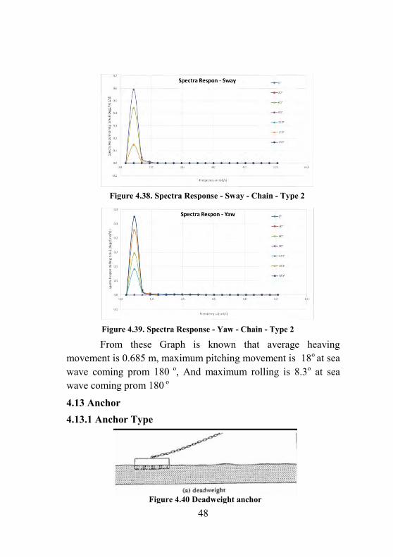
Figure 4.38. Spectra Response - Sway - Chain - Type 2 ...................... 48
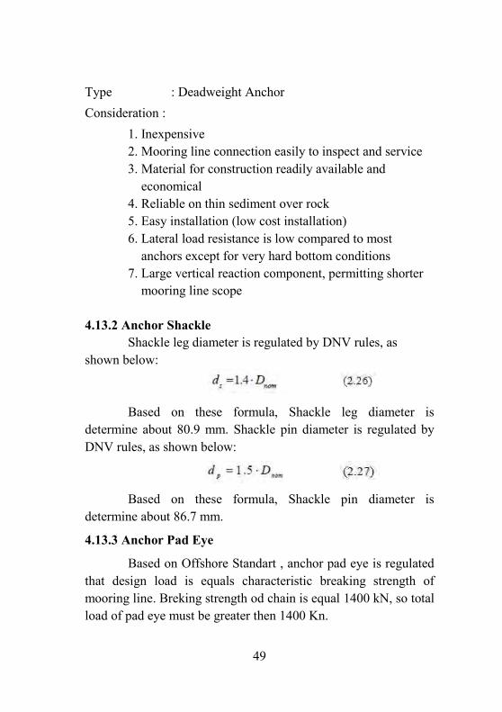
Figure 4.39. Spectra Response - Yaw - Chain - Type 2 ........................ 48
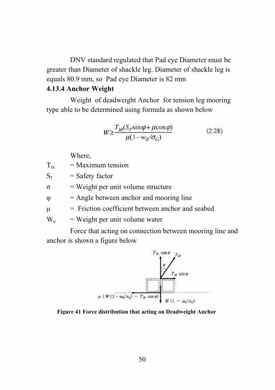
Figure 4.40 Deadweight anchor ......................................................... 48
Figure 41 Force distribution that acting on Deadweight Anchor ........ 50
Figure 4.42 Resultant displacement simulation ................................. 52
Figure 4.43 Pressure testing simulation ............................................. 52
Figure 4.44. AQWA hydrostatic results .............................................. 53
xxi
Tables Table 4.1. Geographic condition ........................................................ 28
Table 4.2. Moment Inertia................................................................. 28
Table 4.3 Advantages and disadvantages of Tension Leg mooring and
catamaran................................................................................. 29
Table 4.4 Coefficient drag regulation ................................................ 34
Table 4.5. Safety factor based on geographic condition .................... 38
Table 4.6 Breaking condition of chain ............................................... 39
Table 4.7 Breaking condition of wire ................................................. 39
Table 4.8 Breaking condition of fiber................................................. 39
Table 4.9 RAO - Heave - Chain - Type 1 .............................................. 40
Table 4.10 RAO - Heave - Wire - Type 1 ............................................. 41
Table 4.11 RAO - Heave - Fiber - Type 1 ............................................. 42
1
Chapter 1
Introduction
1.1 Background
Ocean current energy utilization is one of the energy resources diversify activities to ensure the availability of energy, as clarify in Government Law No. 30/2007 about Energy resource. research and development of science and technology provision and utilization of energy is directed mainly to the development of new energy and renewable energy to support the development of an national energy industry independently. the energy of ocean currents as one of the new and renewable energy can be utilized to solve the problem of electric energy in the isolated archipelago in order to support efforts towards Indonesia became an independent archipelago nation
The energy potential which available in Indonesia, ocean current energy resources are a potential resource to be converted into electrical energy. This is because of the Indonesian archipelago has many narrow strait, which will increase the velocity of water flow to be the heavy sea currents. The technology which can be used to facilitate its geographical conditions is to install turbines that utilize the movement of heavy water flow to rotate the turbine blades that can be converted into electrical energy. Turbines and all other supporting equipment is installed on Floating Platform that built on the deep waters strait
Floating platform of ocean current power plant is located in deep water requires good stability against sea waves, ocean
2
currents, wind and other forces. The stability of Floating Platform is greatly influenced by the selection of mooring system. The right selection of mooring system will reduce the six degree of free movement (Surge, Sway, Heave, Pitch, Sway, and Roll) on Floating Platform. the great, efficient and economic of Mooring system must consider the number of line, line spacing, line diameter, line material, and tension of line.
1.2 Problem Formulation and Scope
Problem Formulation
1. What kind of Mooring line that is safe, efficient, and Economic to maintain the stability of the Floating Platform (Wire rope , fiber or chain system).
2. How many diameter of the mooring line / cable that precise to maintain the stability of the Floating Platform
3. Where the position of mooring line / cable that precise to maintain the stability of the Floating Platform
4. How stability of floating platform based on RAO and Spectrum Response graph on pitch, roll, heave, Surge, sway and Yaw Condition
5. What is anchoring type that is safe, efficient, and Economic to maintain the stability of the Floating Platform
Scope
Currents, waves and winds Force are constant (steady) tide force is not calculated and considered Viscosity is not calculated and considered construction of platform is very rigid and isn’t any
deflection
3
fluid are incompressible, Inviscid, and irrotational Analysis using Ansys Aqwa
1.3 Objective
1. Find out the value of external force/load that acting on the Floating Platform
2. Selecting the kind of Mooring line that are safe, strong, and cheap on the Floating Platform to Reduce 6 degrees of freedom movement
3. Find out line position, line diameter, material line and the tension of line on the Floating Platform mooring system
4. Find out stability of floating platform using RAO and Spectrum Response graph on pitch, roll, heave, Surge, sway and Yaw Condition
5. Find out the weight and type of Anchor include its accessories
1.4 Benefit
Results of the research will be useful in selecting Mooring system that is safe, strong, cheap, and efficient then Floating platform of ocean current power plant to be more stable and all machinery component above platform can operate optimally

4
(This page intentionally left blank)
5
Chapter 2
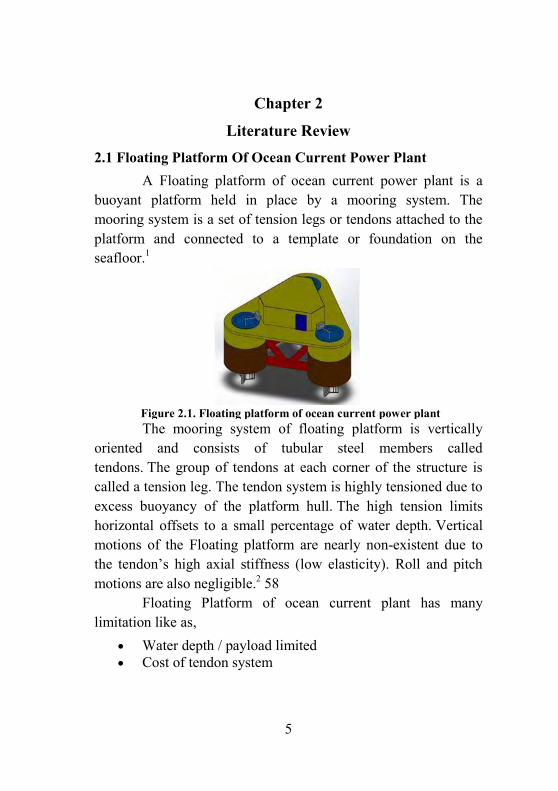
Literature Review 2.1 Floating Platform Of Ocean Current Power Plant A Floating platform of ocean current power plant is a buoyant platform held in place by a mooring system. The mooring system is a set of tension legs or tendons attached to the platform and connected to a template or foundation on the seafloor.1
The mooring system of floating platform is vertically oriented and consists of tubular steel members called tendons. The group of tendons at each corner of the structure is called a tension leg. The tendon system is highly tensioned due to excess buoyancy of the platform hull. The high tension limits horizontal offsets to a small percentage of water depth. Vertical motions of the Floating platform are nearly non-existent due to the tendon’s high axial stiffness (low elasticity). Roll and pitch motions are also negligible.2 58 Floating Platform of ocean current plant has many limitation like as,
Water depth / payload limited Cost of tendon system
Figure 2.1. Floating platform of ocean current power plant
6
Vertical mooring system does not provide active control of horizontal position (e.g., for well access)258
2.2 Environment Loads Environmental loads are those caused by environmental phenomena. The different loads to be considered while designing the structure are wind loads, wave load, mass, damping, ice load, seismic load, current load, dead load, live load, impact load, etc. 1)
2.2.1 Wind Force Wind forces on offshore structures are caused by complex fluid-dynamics phenomenon, which is generally difficult to calculate with high accuracy1). the wind force on a plate orthogonal to the wind flow direction can be determined by the net wind pressure as given below:
where ρa is mass density of air (1.25 kg/m3), and Cw is wind pressure coefficient. It is important to note that the mass density of air increases due to the water spray (splash) up to a height of 20–20 m above MSL. Hence, the total wind-induced force on the plate is given by:
If the plate has an angle (θ) with respect to the wind direction, then the appropriate projected area, normal to the flow direction, should be used in the above equation. The wind pressure coefficient Cw is determined under controlled stationary wind flow conditions in a wind tunnel. 1)
7
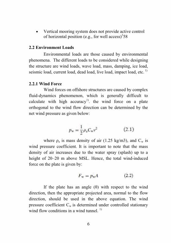
2.2.2 Wave Force Wind-generated sea surface waves shall be represented as a combination of series of regular waves. Regular waves of different magnitude and wave lengths from different directions are combined to represent the sea surface elevation1).
Wave theories serve to calculate the particle velocities, accelerations, and the dynamic pressure as functions of the surface elevation of the waves. For long crested regular waves, the flow can be considered two-dimensional and are characterized by parameters such as wave height (H), period (T) and water depth (d). k ¼ 2p=L denotes the wave number, x ¼ 2p=T denotes the wave circular frequency, and f ¼ 1=T denotes the cyclic frequency Error! Reference source not
found..
The wave particle kinematics can now be used to calculate the loads on a structure with the Morison Equation.
Figure 2.2 Regular sea wave
8
2.2.3 Current Force The presence of current in water produces the following distinct effects: Current velocity should be added vectorially to the horizontal water particle velocity before computing the drag force, because drag force depends on the square of the water particle velocity Error! Reference source not found.. Current decreases slowly with the increase in depth, but even a small magnitude of current velocity can cause significant drag force. This effect is insignificant and generally neglected. Current makes the structure itself to generate waves, which in turn creates diffraction forces. 2) the current on a floating structure can be calculated from2):
Where,
Xc = steady longitudinal current force (N)
Yc = steady lateral current force (N) Nc = steady yaw current moment (Nm) ρ = density of water (kg/m3) Vc = current velocity (m/s) αc = current direction, from astern is zero (rad) ATS ≈ B ∙ T = submerged transverse projected area (m2) ALS ≈ L T = submerged lateral projected area (m2) 2.3 Mooring Line 2.3.1 Chain rope
9
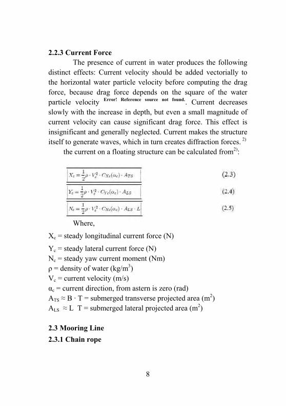
Chains are the most common used mooring lines and are available in different diameters and grades. The most commonly used type of chain mooring line is the stud link chain, which is used for
moorings that have to be reset numerous times during their lifetime, for instance semi-submersibles. The other chain design which is used frequently is a studless chain, which is often used for permanent moorings, like FPSO's, buoys etcetera.3
Chain system has an advantage in overcoming the abrasion, because it has a very strong grip anchor. But, the disadvantage is the heavy chain itself. In the deep water is often to be problem because of the heavy of chain that is too large. 3
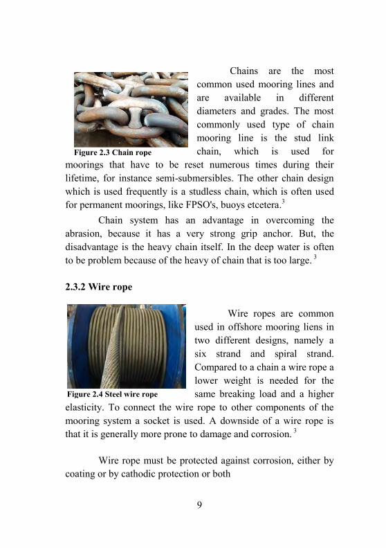
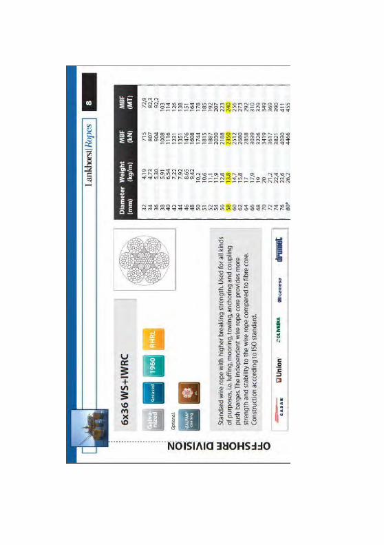
2.3.2 Wire rope Wire ropes are common used in offshore mooring liens in two different designs, namely a six strand and spiral strand. Compared to a chain a wire rope a lower weight is needed for the same breaking load and a higher
elasticity. To connect the wire rope to other components of the mooring system a socket is used. A downside of a wire rope is that it is generally more prone to damage and corrosion. 3
Wire rope must be protected against corrosion, either by coating or by cathodic protection or both
Figure 2.3 Chain rope
Figure 2.4 Steel wire rope
10
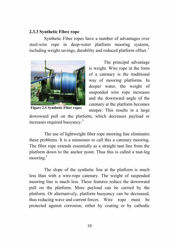
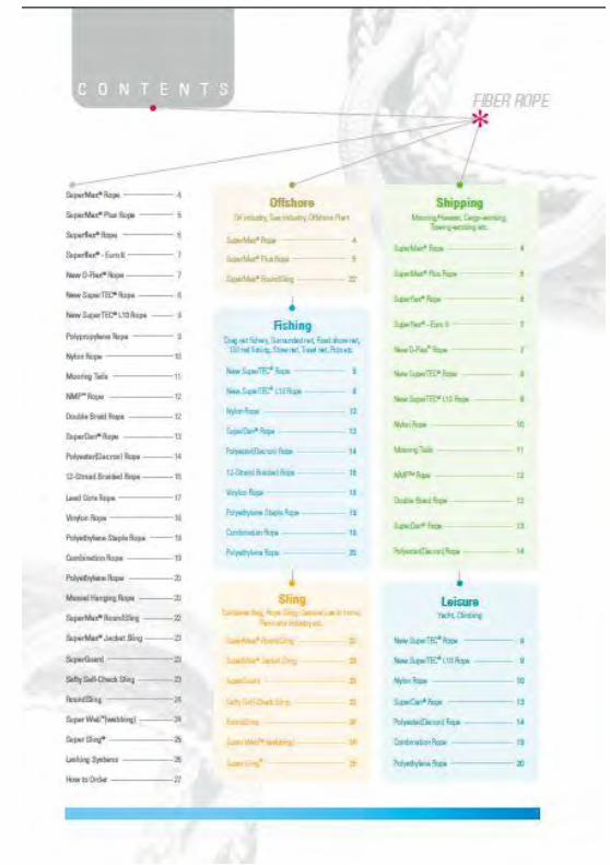
2.3.3 Synthetic Fibre rope Synthetic Fiber ropes have a number of advantages over steel-wire rope in deep-water platform mooring systems, including weight savings, durability and reduced platform offset. 3
The principal advantage is weight. Wire rope in the form of a catenary is the traditional way of mooring platforms. In deeper water, the weight of suspended wire rope increases and the downward angle of the catenary at the platform becomes steeper. This results in a large
downward pull on the platform, which decreases payload or increases required buoyancy.3
The use of lightweight fiber rope mooring line eliminates these problems. It is a misnomer to call this a catenary mooring. The fiber rope extends essentially as a straight taut line from the platform down to the anchor point. Thus this is called a taut-leg mooring.3
The slope of the synthetic line at the platform is much less than with a wire-rope catenary. The weight of suspended mooring line is much less. These features reduce the downward pull on the platform. More payload can be carried by the platform. Or alternatively, platform buoyancy can be decreased, thus reducing wave and current forces. Wire rope must be protected against corrosion, either by coating or by cathodic
Figure 2.5 Synthetic Fiber ropes
11
protection or both. Synthetic fiber does not corrode. This is an obvious advantage. Error! Reference source not found.
2.4 Mooring System 2.4.1 Catenary mooring
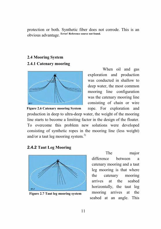
When oil and gas exploration and production was conducted in shallow to deep water, the most common mooring line configuration was the catenary mooring line consisting of chain or wire rope. For exploration and
production in deep to ultra-deep water, the weight of the mooring line starts to become a limiting factor in the design of the floater. To overcome this problem new solutions were developed consisting of synthetic ropes in the mooring line (less weight) and/or a taut leg mooring system.3)
2.4.2 Taut Leg Mooring The major difference between a catenary mooring and a taut leg mooring is that where the catenary mooring arrives at the seabed horizontally, the taut leg mooring arrives at the
seabed at an angle. This
Figure 2.6 Catenary mooring System
Figure 2.7 Taut leg mooring system
12
means that in a taut leg mooring the anchor point has to be capable of resisting both horizontal and vertical forces, while in a catenary mooring the anchor point is only subjected to horizontal forces. In a catenary mooring, most of the restoring forces are generated by the weight of the mooring line. In a taut leg mooring, the restoring forces are generated by the elasticity of the mooring line.3) An advantage of a taut leg mooring over the catenary mooring is that it has a smaller footprint, i.e. the mooring radius of the taut leg mooring will be smaller than for a catenary mooring for a similar application. This reduces the material quantity, cost and weight of the total mooring system.3)
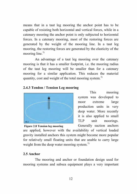
2.4.3 Tendon / Tension Leg mooring This mooring system was developed to moor extreme large production units in very deep water. More recently it is also applied to small TLP unit moorings. Generally suction anchors
are applied, however with the availability of vertical loaded gravity installed anchors this system might become more popular for relatively small floating units that are unable to carry large weight from the deep water mooring system.3)
2.5 Anchor The mooring and anchor or foundation design used for mooring systems and subsea equipment plays a very important
Figure 2.8 Tension leg mooring
13
role in the lifecycle. All over the world their exist difference in bottom soil conditions. These soil conditions have a big influence on the load capacity of any anchor system. A greater load capacity of any anchor can be achieved by a deeper embedding, also the greater quantity of affected soil. Therefore permanent anchors can be designed for different types of soils.3)
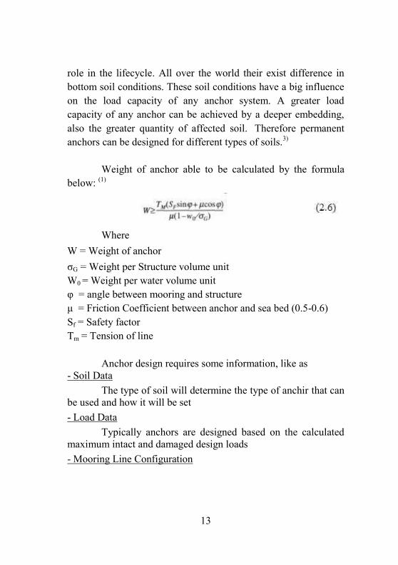
Weight of anchor able to be calculated by the formula below: (1)
Where W = Weight of anchor σG = Weight per Structure volume unit W0 = Weight per water volume unit φ = angle between mooring and structure μ = Friction Coefficient between anchor and sea bed (0.5-0.6) Sf = Safety factor Tm = Tension of line Anchor design requires some information, like as - Soil Data The type of soil will determine the type of anchir that can be used and how it will be set - Load Data Typically anchors are designed based on the calculated maximum intact and damaged design loads - Mooring Line Configuration
14
Configuration of mooring line based on installation type of mooring ( Catenary, taut leg mooring, etc) and type of mooring line (chain, wire, or fiber). 3) A deeper the embedment, the greater the pull-out load, which is the key to maximize the load. Since horizontal loads can embed themselves deeper, vertical loads will take more effort to get deeper. Vertical loaded anchors are therefore more expensive to install. Finding a relatively cheap anchoring system with a high vertical load capacity that is easy to install will be very challenging. types of seafloor is listed below.3
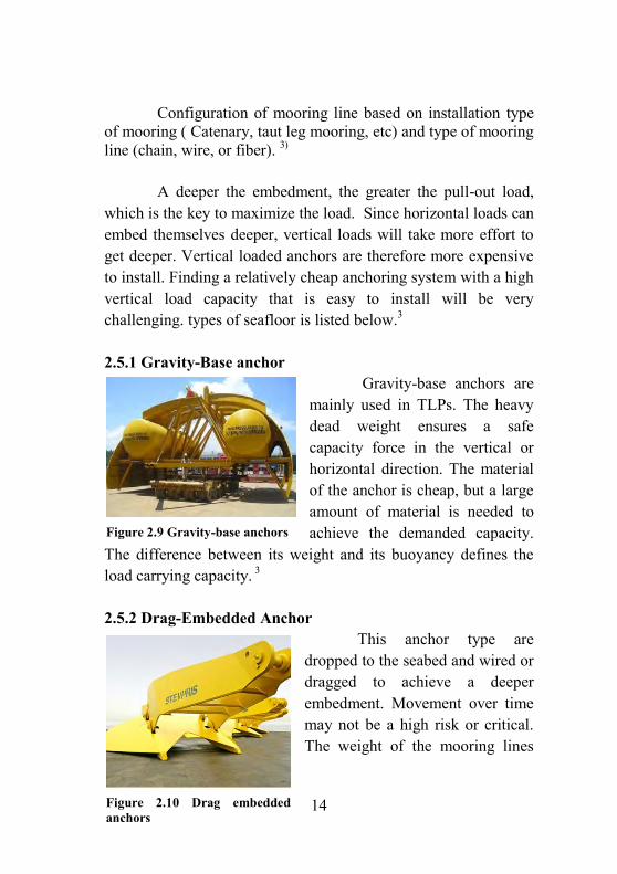
2.5.1 Gravity-Base anchor Gravity-base anchors are mainly used in TLPs. The heavy dead weight ensures a safe capacity force in the vertical or horizontal direction. The material of the anchor is cheap, but a large amount of material is needed to achieve the demanded capacity.
The difference between its weight and its buoyancy defines the load carrying capacity. 3
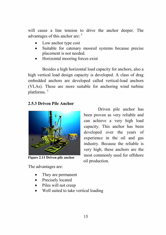
2.5.2 Drag-Embedded Anchor This anchor type are dropped to the seabed and wired or dragged to achieve a deeper embedment. Movement over time may not be a high risk or critical. The weight of the mooring lines
Figure 2.9 Gravity-base anchors
Figure 2.10 Drag embedded anchors
15
will cause a line tension to drive the anchor deeper. The advantages of this anchor are: 3
Low anchor type cost Suitable for catenary moored systems because precise
placement is not needed. Horizontal mooring forces exist
Besides a high horizontal load capacity for anchors, also a high vertical load design capacity is developed. A class of drag embedded anchors are developed called vertical-load anchors (VLAs). These are more suitable for anchoring wind turbine platforms. 3
2.5.3 Driven Pile Anchor Driven pile anchor has been proven as very reliable and can achieve a very high load capacity. This anchor has been developed over the years of experience in the oil and gas industry. Because the reliable is very high, these anchors are the most commonly used for offshore oil production.
The advantages are:
They are permanent Precisely located Piles will not creep Well suited to take vertical loading
Figure 2.11 Driven pile anchor
16
A disadvantage can be the high cost. By using a vibratory or impact hammer, the drivepile anchor is driven into the seafloor. 3
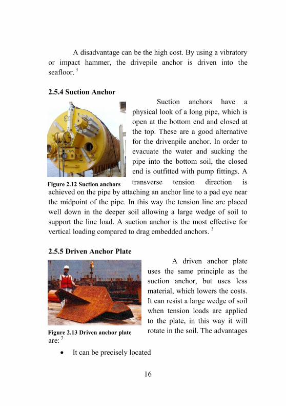
2.5.4 Suction Anchor Suction anchors have a physical look of a long pipe, which is open at the bottom end and closed at the top. These are a good alternative for the drivenpile anchor. In order to evacuate the water and sucking the pipe into the bottom soil, the closed end is outfitted with pump fittings. A transverse tension direction is
achieved on the pipe by attaching an anchor line to a pad eye near the midpoint of the pipe. In this way the tension line are placed well down in the deeper soil allowing a large wedge of soil to support the line load. A suction anchor is the most effective for vertical loading compared to drag embedded anchors. 3
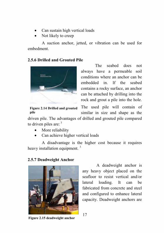
2.5.5 Driven Anchor Plate A driven anchor plate uses the same principle as the suction anchor, but uses less material, which lowers the costs. It can resist a large wedge of soil when tension loads are applied to the plate, in this way it will rotate in the soil. The advantages
are: 3 It can be precisely located
Figure 2.12 Suction anchors
Figure 2.13 Driven anchor plate
17
Can sustain high vertical loads Not likely to creep
A suction anchor, jetted, or vibration can be used for embedment.
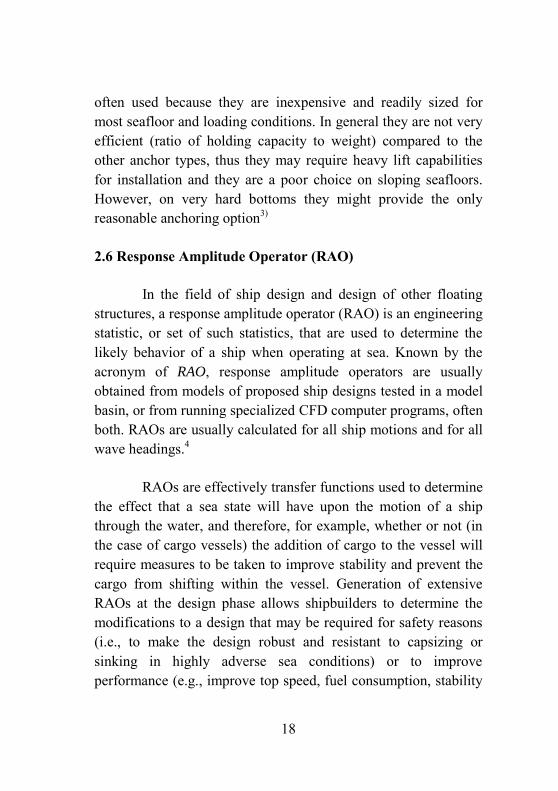
2.5.6 Drilled and Grouted Pile The seabed does not always have a permeable soil conditions where an anchor can be embedded in. If the seabed contains a rocky surface, an anchor can be attached by drilling into the rock and grout a pile into the hole.
The used pile will contain of similar in size and shape as the
driven pile. The advantages of drilled and grouted pile compared to driven piles are: 3
More reliability Can achieve higher vertical loads
A disadvantage is the higher cost because it requires heavy installation equipment. 3
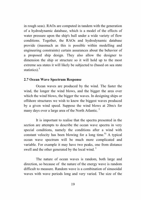
2.5.7 Deadweight Anchor A deadweight anchor is any heavy object placed on the seafloor to resist vertical and/or lateral loading. It can be fabricated from concrete and steel and configured to enhance lateral capacity. Deadweight anchors are
Figure 2.14 Drilled and grouted pile
Figure 2.15 deadweight anchor
18
often used because they are inexpensive and readily sized for most seafloor and loading conditions. In general they are not very efficient (ratio of holding capacity to weight) compared to the other anchor types, thus they may require heavy lift capabilities for installation and they are a poor choice on sloping seafloors. However, on very hard bottoms they might provide the only reasonable anchoring option3)
2.6 Response Amplitude Operator (RAO)
In the field of ship design and design of other floating structures, a response amplitude operator (RAO) is an engineering statistic, or set of such statistics, that are used to determine the likely behavior of a ship when operating at sea. Known by the acronym of RAO, response amplitude operators are usually obtained from models of proposed ship designs tested in a model basin, or from running specialized CFD computer programs, often both. RAOs are usually calculated for all ship motions and for all wave headings.4
RAOs are effectively transfer functions used to determine the effect that a sea state will have upon the motion of a ship through the water, and therefore, for example, whether or not (in the case of cargo vessels) the addition of cargo to the vessel will require measures to be taken to improve stability and prevent the cargo from shifting within the vessel. Generation of extensive RAOs at the design phase allows shipbuilders to determine the modifications to a design that may be required for safety reasons (i.e., to make the design robust and resistant to capsizing or sinking in highly adverse sea conditions) or to improve performance (e.g., improve top speed, fuel consumption, stability
19
in rough seas). RAOs are computed in tandem with the generation of a hydrodynamic database, which is a model of the effects of water pressure upon the ship's hull under a wide variety of flow conditions. Together, the RAOs and hydrodynamic database provide (inasmuch as this is possible within modelling and engineering constraints) certain assurances about the behavior of a proposed ship design. They also allow the designer to dimension the ship or structure so it will hold up to the most extreme sea states it will likely be subjected to (based on sea state statistics).5
2.7 Ocean Wave Spectrum Response
Ocean waves are produced by the wind. The faster the wind, the longer the wind blows, and the bigger the area over which the wind blows, the bigger the waves. In designing ships or offshore structures we wish to know the biggest waves produced by a given wind speed. Suppose the wind blows at 20m/s for many days over a large area of the North Atlantic. 5
It is important to realise that the spectra presented in the section are attempts to describe the ocean wave spectra in very special conditions, namely the conditions after a wind with constant velocity has been blowing for a long time.8) A typical ocean wave spectrum will be much more complicated and variable. For example it may have two peaks, one from distance swell and the other generated by the local wind. 5
The nature of ocean waves is random, both large and direction, so because of the nature of the energy wave is random difficult to measure. Random wave is a combination of sinusoidal waves with wave periods long and very varied. The size of the

20
random wave component intensity is generally expressed in terms of spectrum amplitude density, wave energy density, or commonly abbreviated to be wave energy spectrum. 5)
Based on DNV RP C205 (2010), The Pierson-Moskowitz spectra is given by14):
where p = 2/Tp is the angular spectral peak frequency
The JONSWAP spectrum is formulated as a modification of the Pierson-Moskowitz spectrum for a developing sea state in a fetch limited situation:
Where, SPM() = Pierson-Moskowitz spectrum = non-dimensional peak shape parameter = spectral width parameter = a for p
= b for > p
A = 1- 0.287 ln() is a normalizing factor
2.8 Ansys AQWA
ANSYS AQWA provides an engineering toolset for the investigation of the effects of wave, wind and current on floating and fixed offshore and marine structures, including: spars; floating production, storage, and offloading (FPSO) systems; semi-submersibles; tension leg platforms (TLPs); ships; renewable energy systems; and breakwater design.15)
21
AQWA Hydrodynamic Diffraction provides an integrated environment for developing the primary hydrodynamic parameters required for undertaking complex motions and response analyses. AQWA Hydrodynamic Diffraction can also generate pressure and inertial loading for use in a structural analysis as part of the vessel hull design process. 15)
AQWA Hydrodynamic Time Response provides dynamic analysis capabilities for undertaking global performance assessment of floating structures in the time domain. A wide range of physical connections, such as mooring lines, fenders, and articulations, are provided to model the restraining conditions on the vessels. In addition, sea-keeping simulation may be undertaken with the inclusion of forward speed effects. Slow-drift effects and extreme-wave conditions may be investigated, and damage conditions, such as line breakage, may be included to study any transient effects that may occur. 15)
23
Chapter 3
Research Methodology 1. Literature Studies Find out a general overview of the mooring system, 6 degrees of freedom movement, and stability on the Floating Platform Effectively and efficiently. Literature is obtained from books, journal maritime, audit reports of companies, and the official website which can be responsible its information
2. Searching and Inputting data Searching and Inputting data such as Design Platform, General Arrangement Platform, depth and contour of the trough, the current velocity, wind velocity, and Wave velocity
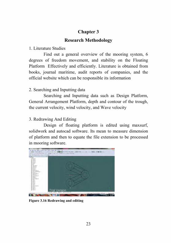
3. Redrawing And Editing Design of floating platform is edited using maxsurf, solidwork and autocad software. Its mean to measure dimension of platform and then to equate the file extension to be processed in mooring software.
Figure 3.16 Redrawing and editing
24
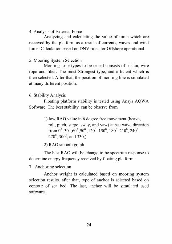
4. Analysis of External Force Analyzing and calculating the value of force which are received by the platform as a result of currents, waves and wind force. Calculation based on DNV rules for Offshore operational
5. Mooring System Selection Mooring Line types to be tested consists of chain, wire rope and fiber. The most Strongest type, and efficient which is then selected. After that, the position of mooring line is simulated at many different position.
6. Stability Analysis Floating platform stability is tested using Ansys AQWA Software. The best stability can be observe from
1) low RAO value in 6 degree free movement (heave, roll, pitch, surge, sway, and yaw) at sea wave direction from 00 ,300 ,600 ,900 ,1200, 1500, 1800, 2100, 2400, 2700, 3000, and 330,)
2) RAO smooth graph
The best RAO will be change to be spectrum response to determine energy frequency received by floating platform.
7. Anchoring selection Anchor weight is calculated based on mooring system selection results. after that, type of anchor is selected based on contour of sea bed. The last, anchor will be simulated used software.
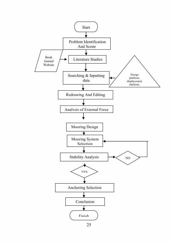
25
Start
Literature Studies
Searching & Inputting data
Redrawing And Editing
Analysis of External Force
Mooring System Selection
YES
NO
Book Journal Website
Design platform,
displacement platform, general
Problem Identification And Scope
Anchoring Selection
Conclusion
Finish
Stability Analysis
Mooring Design

26
(This page intentionally left blank)
27
Chapter 4
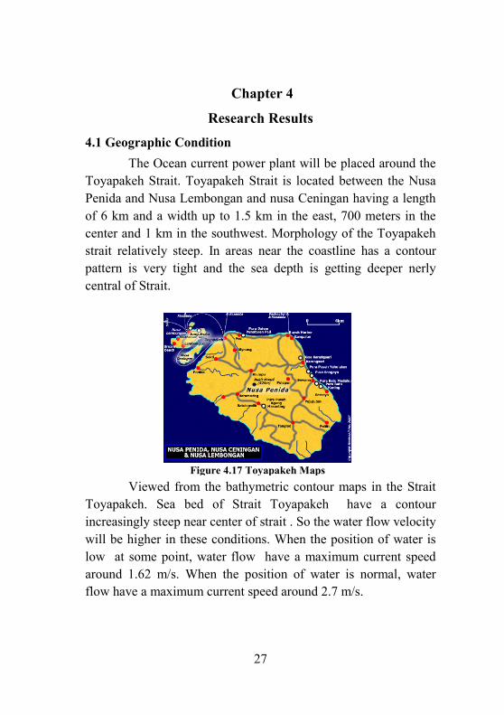
Research Results 4.1 Geographic Condition The Ocean current power plant will be placed around the Toyapakeh Strait. Toyapakeh Strait is located between the Nusa Penida and Nusa Lembongan and nusa Ceningan having a length of 6 km and a width up to 1.5 km in the east, 700 meters in the center and 1 km in the southwest. Morphology of the Toyapakeh strait relatively steep. In areas near the coastline has a contour pattern is very tight and the sea depth is getting deeper nerly central of Strait.
Viewed from the bathymetric contour maps in the Strait Toyapakeh. Sea bed of Strait Toyapakeh have a contour increasingly steep near center of strait . So the water flow velocity will be higher in these conditions. When the position of water is low at some point, water flow have a maximum current speed around 1.62 m/s. When the position of water is normal, water flow have a maximum current speed around 2.7 m/s.
Figure 4.17 Toyapakeh Maps
28
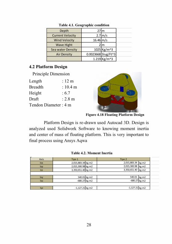
4.2 Platform Design Principle Dimension Length : 12 m Breadth : 10.4 m Height : 6.7 Draft : 2.8 m Tendon Diameter : 4 m
Platform Design is re-drawn used Autocad 3D. Design is analyzed used Solidwork Software to knowing moment inertia and center of mass of floating platform. This is very important to final process using Ansys Aqwa
Axis
Ixx kg.m2 kg.m2
Iyy kg.m2 kg.m2
Izz kg.m2 kg.m2
Ixy kg.m2 kg.m2
lxz kg.m2 kg.m2
Iyz kg.m2 kg.m2-1,127.21
-680.27
540.01
3,350,651.40
2,015,300.98
-1,127.21
-680.27
540.01
2,015,883.34
2,015,300.98
3,350,651.40
Tipe 1
2,015,883.34
Tipe 2
Figure 4.18 Floating Platform Design
Table 4.2. Moment Inertia
27 m
2.7 m/s
16.46 m/s
2 m
1025 Kg/m^3
0.0023668 Slug/Ft^3
1.219 Kg/m^3
Air Density
Depth
Current Velocity
Wind Velocity
Wave Hight
Sea water Density
Table 4.1. Geographic condition
29
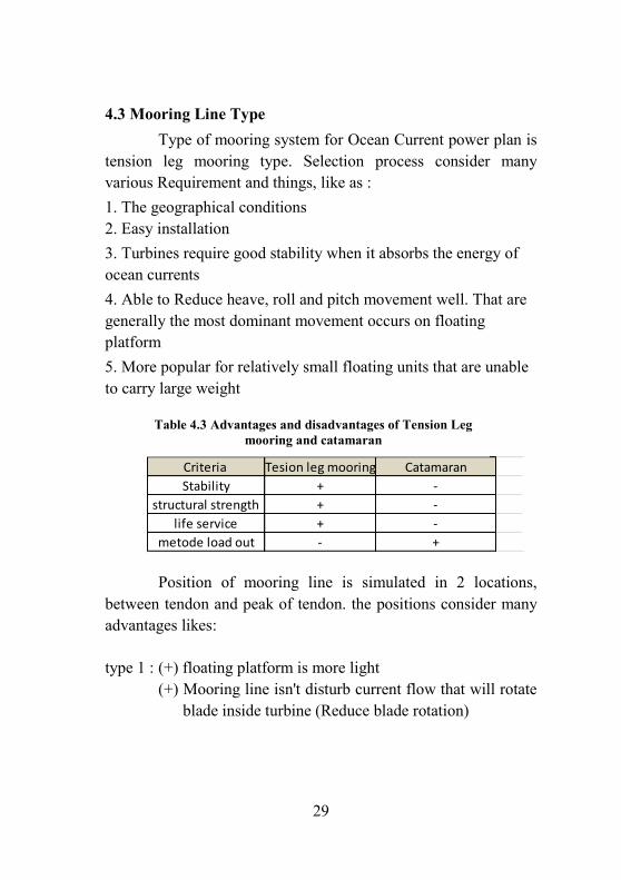
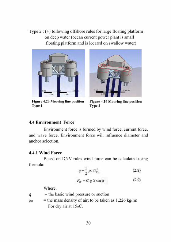
4.3 Mooring Line Type Type of mooring system for Ocean Current power plan is tension leg mooring type. Selection process consider many various Requirement and things, like as : 1. The geographical conditions 2. Easy installation 3. Turbines require good stability when it absorbs the energy of ocean currents 4. Able to Reduce heave, roll and pitch movement well. That are generally the most dominant movement occurs on floating platform 5. More popular for relatively small floating units that are unable to carry large weight
Position of mooring line is simulated in 2 locations, between tendon and peak of tendon. the positions consider many advantages likes:
type 1 : (+) floating platform is more light (+) Mooring line isn't disturb current flow that will rotate blade inside turbine (Reduce blade rotation)
Criteria Tesion leg mooring
Stability +
structural strength +
life service +
metode load out -
Catamaran
-
+
-
-
Table 4.3 Advantages and disadvantages of Tension Leg mooring and catamaran
30
Type 2 : (+) following offshore rules for large floating platform on deep water (ocean current power plant is small floating platform and is located on swallow water)
4.4 Environment Force Environment force is formed by wind force, current force, and wave force. Environment force will influence diameter and anchor selection.
4.4.1 Wind Force Based on DNV rules wind force can be calculated using formula: Where, q = the basic wind pressure or suction a = the mass density of air; to be taken as 1.226 kg/m3
For dry air at 15oC.
Figure 4.20 Mooring line position Type 1
Figure 4.19 Mooring line position Type 2

31
UT,z = the wind velocity averaged over a time C = shape coefficient q = basic wind pressure or suction, S = projected area of the member normal to the direction of the force = angle between the direction of the wind and the axis of the exposed member or surface. From These formula, after calculation is known that total wind force is 0.86 kN
4.4.2 Current Force Current force can be calculated using Morison equation, like is shown below :
Where,
F = Current force Fd = drag force F1 = inertia force Cd = Inertia coefficient Cm = Inertia coefficient W = weight density of water A = projected area normal to the cylinder (= D for circular cylinders) V = displaced volume of the cylinder (= πD^2/4 for circular cylinders) g = gravitational acceleration
Figure 21 Drag and inertia force
32
After calculation is known drag force about 367.12 N, inertia force about 2101.88 N , so current force about 2468.995 N or 2.47 kN
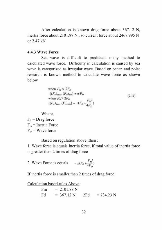
4.4.3 Wave Force Sea wave is difficult to predicted, many method to calculated wave force. Difficulty in calculation is caused by sea wave is categorized as irregular wave. Based on ocean and polar research is known method to calculate wave force as shown below
Where, Fd = Drag force Fm = Inertia Force Fw = Wave force Based on regulation above ,then : 1. Wave force is equals Inertia force, if total value of inertia force is greater than 2 times of drag force 2. Wave Force is equals If inertia force is smaller than 2 times of drag force. Calculation based rules Above: Fm = 2101.88 N Fd = 367.12 N 2Fd = 734.23 N
33
Result : Fm ≥ 2FD Summary : wave force = Fm = 2101.88 N = 2.1 kN 4.4.4 Environment Force Environment force or load is equal total load of wind force, current force and wave force.
Tf = Wind force + current force + wave force = 0.84 kN + 2.47 kN + 2.1 kN = 5.41 kN This calculation on normal condition and wave,wind and current comes from same directSion
4.5 Mooring Line Material
There are 3 types of mooring line that will be consider to be Selected for floating platform: chain, wire rope dan Fibre rope. 4.5.1 Chain Type : Studless chain Consideration : - Low cost compared Studlink Chain - Weight is not predominantly important - Long lifetime 4.5.2 Wire Type : Wire Rope, Six Strand Consideration : 1. Low Cost 2. Easy Maintenance 3. Light
34
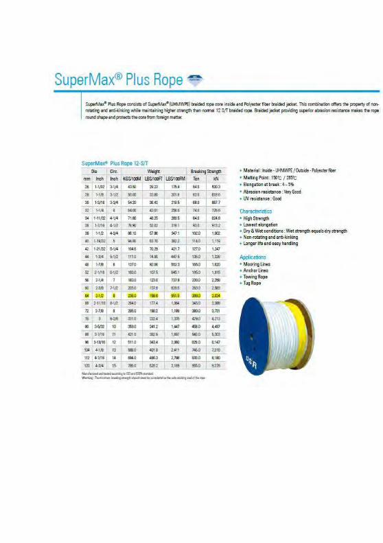
4.5.3 Fiber Type : Polyester Fiber Consideration : 1. Low Cost 2. Providing superior abrasion resistance 3. Light
4.6 Nominal Diameter
Nominal diameter is regulated on DNV rules as shown below:
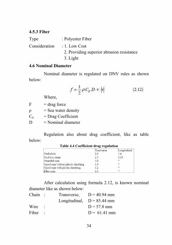
Where, F = drag force ρ = Sea water density Cd = Drag Coefficient D = Nominal diameter Regulation also about drag coefficient, like as table below:
Table 4.4 Coefficient drag regulation
After calculation using formula 2.12, is known nominal diameter like as shown below: Chain : Transverse, D = 40.94 mm Longitudinal, D = 85.44 mm Wire : D = 57.8 mm Fiber : D = 61.41 mm
35
4.7 Mooring line Specification after knowing the nominal diameter, rope specifications can be searched through a brochure with matching line diameter rope, function, and geography conditions.
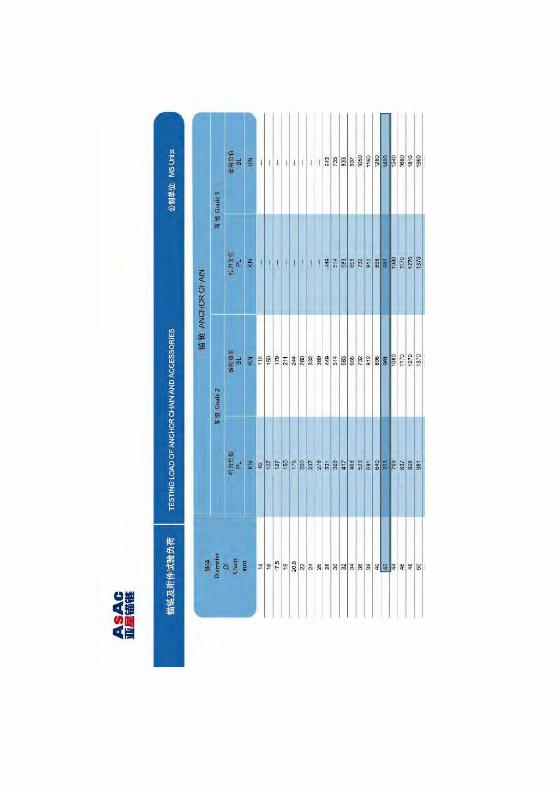
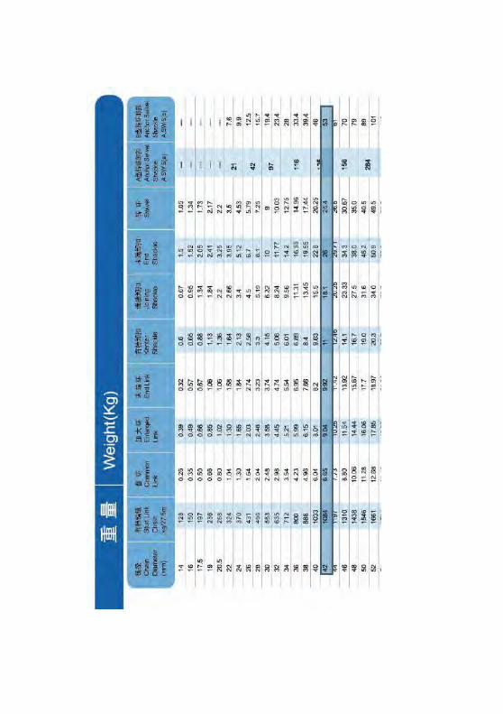
a. Chain Merk : ASAC Type : Studless Chain Grade : R3 Diameter : 42 mm Weight : 39.4 kg/m Weight total : 973.18 kg/m Breaking load : 1400 kN Prof load : 981 kN b. Wire Merk : Lankhorst Diameter : 58 mm Weight : 17 Kg/m Total Weight : 419.9 Kg Breaking Strength : 2350 kN c. Fiber Merk : Supermax Diameter : 64 mm Weight : 236 Kg/100m Total Weight : 58.29 Kg Breaking Strength : 3024 kN
4.8 Axial Stiffness
axial stiffness has a different value depending on the type of rope. axial stiffness can be determined with knowing diameter
36
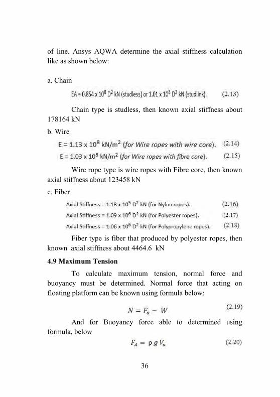
of line. Ansys AQWA determine the axial stiffness calculation like as shown below: a. Chain Chain type is studless, then known axial stiffness about 178164 kN
b. Wire
Wire rope type is wire ropes with Fibre core, then known axial stiffness about 123458 kN
c. Fiber
Fiber type is fiber that produced by polyester ropes, then known axial stiffness about 4464.6 kN
4.9 Maximum Tension To calculate maximum tension, normal force and buoyancy must be determined. Normal force that acting on floating platform can be known using formula below: And for Buoyancy force able to determined using formula, below
37
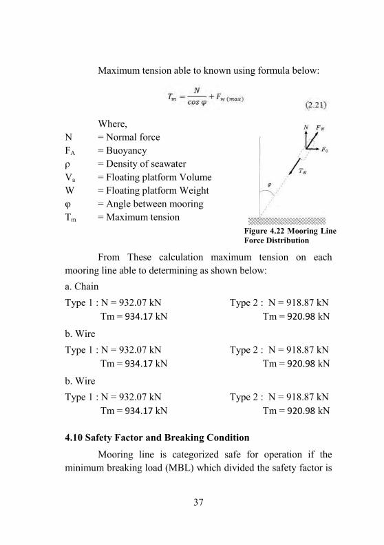
Maximum tension able to known using formula below: Where, N = Normal force FA = Buoyancy ρ = Density of seawater Va = Floating platform Volume W = Floating platform Weight φ = Angle between mooring Tm = Maximum tension From These calculation maximum tension on each mooring line able to determining as shown below: a. Chain Type 1 : N = 932.07 kN Type 2 : N = 918.87 kN Tm = 934.17 kN Tm = 920.98 kN
b. Wire Type 1 : N = 932.07 kN Type 2 : N = 918.87 kN Tm = 934.17 kN Tm = 920.98 kN
b. Wire Type 1 : N = 932.07 kN Type 2 : N = 918.87 kN Tm = 934.17 kN Tm = 920.98 kN
4.10 Safety Factor and Breaking Condition
Mooring line is categorized safe for operation if the minimum breaking load (MBL) which divided the safety factor is
Figure 4.22 Mooring Line Force Distribution
38
smaller than the maximum tension, and the mooring line would break otherwise.
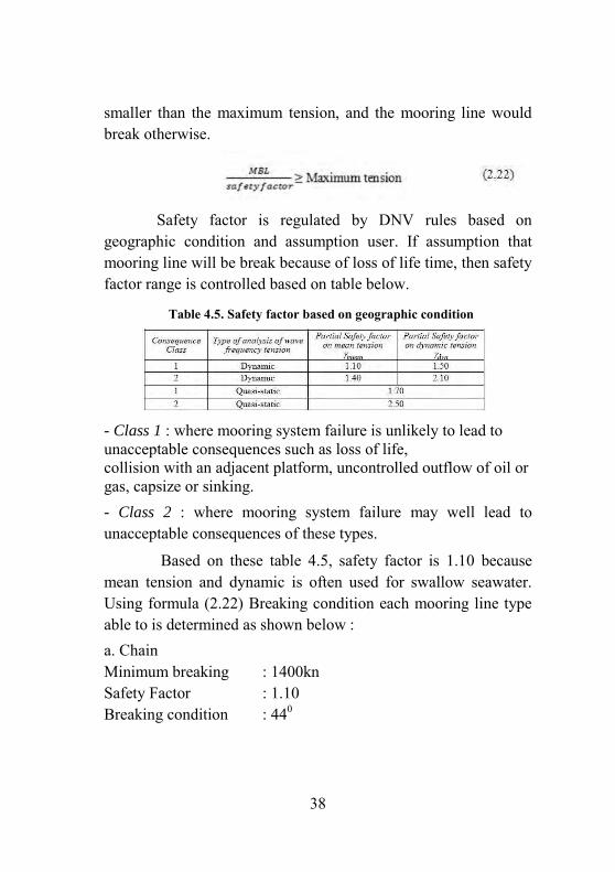
Safety factor is regulated by DNV rules based on geographic condition and assumption user. If assumption that mooring line will be break because of loss of life time, then safety factor range is controlled based on table below.
- Class 1 : where mooring system failure is unlikely to lead to unacceptable consequences such as loss of life, collision with an adjacent platform, uncontrolled outflow of oil or gas, capsize or sinking. - Class 2 : where mooring system failure may well lead to unacceptable consequences of these types.
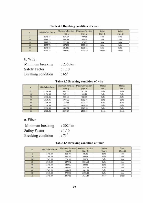
Based on these table 4.5, safety factor is 1.10 because mean tension and dynamic is often used for swallow seawater. Using formula (2.22) Breaking condition each mooring line type able to is determined as shown below : a. Chain Minimum breaking : 1400kn Safety Factor : 1.10 Breaking condition : 440
Table 4.5. Safety factor based on geographic condition
39
b. Wire Minimum breaking : 2350kn Safety Factor : 1.10 Breaking condition : 650
c. Fiber Minimum breaking : 3024kn Safety Factor : 1.10 Breaking condition : 710
0
10
20
30
40
44
ϕStatus
(Tipe 2)
Break
Safe
920.98
935.15
979.95
1063.00
1201.61
1279.49
Maximum Tension
(Tipe 2)
Status
(tipe 1)
Safe
Safe
Safe
Safe
1272.73
948.551272.73
934.17
Maximum Tension
(Tipe 1)MBL/Safety factor
Break
Safe
Safe
Safe
Safe
Safe1272.73
1297.831272.73
1218.831272.73
1078.361272.73
993.99
Table 4.6 Breaking condition of chain
0
10
20
30
40
50
60
65
Safe
Safe
Safe
Break
Safe
Safe
Safe
Safe
Safe
Safe
Safe
Break
Safe
Safe
Safe
Safe
ϕ MBL/Safety factorStatus
(Tipe 1)
Maximum Tension
(tipe 1)
Maximum Tension
(tipe 2)
2136.36 1453.00 1432.48
2208.87
1867.34
2177.65
1840.95
2136.36
2136.36
2136.36 1079.00 1063.76
2136.36 1219.55 1202.33
2136.36 949.11 935.71
2136.36 994.58 980.54
2136.36 934.72 921.53
Status
(Tipe 2)
Table 4.7 Breaking condition of wire
0
10
20
30
40
50
60
70
71 BreakBreak2749.09 2867.81 2827.28
ϕ MBL/Safety factorMaximum Tension
(tipe 1)
Maximum Tension
(tipe 2)
Status
(Tipe 1)
Safe
Safe
Safe
Safe
Safe
Safe
Safe
Safe
Safe
Safe
Safe
Safe
Status
(Tipe 2)
Safe
Safe
Safe
Safe
2749.09 935.08 921.89
2749.09 949.48 936.08
2749.09 994.96 980.92
2749.09 2729.96 2691.38
2749.09 1453.57 1433.04
2749.09 1868.07 1841.68
2749.09 1079.42 1064.18
2749.09 1220.02 1202.8
Table 4.8 Breaking condition of fiber
40
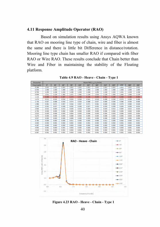
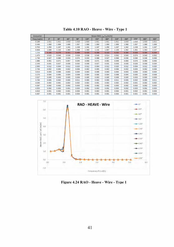
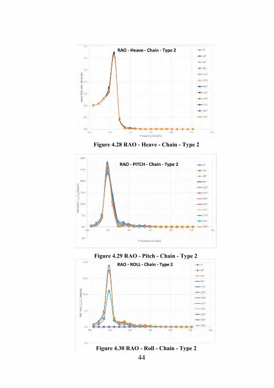
4.11 Response Amplitude Operator (RAO)
Based on simulation results using Ansys AQWA known that RAO on mooring line type of chain, wire and fiber is almost the same and there is little bit Difference in distance/rotation. Mooring line type chain has smaller RAO if compared with fiber RAO or Wire RAO. These results conclude that Chain better than Wire and Fiber in maintaining the stability of the Floating platform.
Figure 4.23 RAO - Heave - Chain - Type 1
Table 4.9 RAO - Heave - Chain - Type 1 Encounter
Freq (rad/s) 0ᵒ 30ᵒ 60ᵒ 90ᵒ 120ᵒ 150ᵒ 180ᵒ 210ᵒ 240ᵒ 270ᵒ 300ᵒ 330ᵒ
0.189 1.011 1.011 1.011 1.011 1.011 1.011 1.011 1.011 1.011 1.011 1.011 1.011
0.446 1.069 1.069 1.068 1.068 1.068 1.069 1.069 1.069 1.068 1.068 1.068 1.069
0.703 1.252 1.249 1.243 1.240 1.243 1.249 1.252 1.249 1.243 1.241 1.243 1.249
0.959 1.011 1.134 1.362 1.471 1.362 1.134 1.010 1.128 1.355 1.464 1.356 1.129
1.216 6.045 6.158 6.307 6.373 6.305 6.156 6.043 6.091 6.280 6.393 6.280 6.093
1.473 0.511 0.541 0.534 0.524 0.534 0.541 0.510 0.498 0.536 0.570 0.536 0.499
1.730 0.027 0.088 0.033 0.074 0.033 0.088 0.027 0.068 0.036 0.096 0.036 0.068
1.986 0.061 0.071 0.057 0.044 0.057 0.071 0.061 0.049 0.059 0.070 0.060 0.049
2.243 0.031 0.027 0.030 0.032 0.030 0.027 0.031 0.033 0.030 0.026 0.030 0.033
2.500 0.012 0.004 0.012 0.020 0.012 0.004 0.012 0.020 0.012 0.004 0.012 0.020
2.756 0.002 0.005 0.002 0.006 0.002 0.005 0.002 0.006 0.002 0.005 0.002 0.006
3.013 0.003 0.006 0.003 0.004 0.003 0.006 0.003 0.004 0.003 0.006 0.003 0.004
3.270 0.004 0.005 0.004 0.008 0.004 0.005 0.004 0.008 0.004 0.005 0.004 0.008
3.527 0.005 0.003 0.005 0.009 0.005 0.003 0.005 0.009 0.005 0.003 0.005 0.009
3.783 0.005 0.002 0.005 0.011 0.005 0.002 0.005 0.011 0.005 0.002 0.005 0.011
4.040 0.002 0.001 0.002 0.002 0.002 0.001 0.002 0.002 0.002 0.001 0.002 0.002
4.297 0.002 0.002 0.002 0.003 0.002 0.002 0.002 0.003 0.002 0.002 0.002 0.003
4.553 0.001 0.003 0.001 0.003 0.002 0.003 0.001 0.003 0.001 0.003 0.001 0.003
4.810 0.001 0.002 0.001 0.004 0.001 0.002 0.001 0.004 0.001 0.002 0.001 0.004
5.067 0.001 0.001 0.001 0.003 0.001 0.001 0.001 0.003 0.001 0.001 0.001 0.003
Heave RAO, zx0 / z0 (m/m)
41
Encounter
Freq (rad/s) 0ᵒ 30ᵒ 60ᵒ 90ᵒ 120ᵒ 150ᵒ 180ᵒ 210ᵒ 240ᵒ 270ᵒ 300ᵒ 330ᵒ
0.189 1.011 1.011 1.010 1.010 1.010 1.011 1.011 1.011 1.010 1.010 1.010 1.011
0.446 1.069 1.069 1.068 1.067 1.068 1.069 1.069 1.069 1.068 1.067 1.068 1.069
0.703 1.250 1.247 1.241 1.238 1.241 1.247 1.250 1.247 1.242 1.239 1.241 1.247
0.959 1.008 1.132 1.360 1.468 1.359 1.131 1.007 1.126 1.352 1.461 1.353 1.127
1.216 6.155 6.270 6.421 6.489 6.420 6.268 6.153 6.202 6.394 6.509 6.394 6.204
1.473 0.515 0.545 0.539 0.528 0.538 0.545 0.514 0.502 0.540 0.574 0.540 0.502
1.730 0.027 0.088 0.033 0.074 0.033 0.088 0.027 0.068 0.036 0.096 0.036 0.068
1.986 0.061 0.071 0.057 0.045 0.058 0.071 0.061 0.049 0.060 0.070 0.060 0.050
2.243 0.031 0.027 0.030 0.032 0.030 0.027 0.031 0.033 0.030 0.026 0.030 0.034
2.500 0.012 0.004 0.012 0.020 0.012 0.004 0.012 0.020 0.012 0.004 0.012 0.020
2.756 0.002 0.005 0.002 0.006 0.002 0.005 0.002 0.006 0.002 0.005 0.002 0.006
3.013 0.003 0.006 0.003 0.004 0.003 0.006 0.003 0.004 0.003 0.006 0.003 0.004
3.270 0.004 0.005 0.004 0.008 0.004 0.005 0.004 0.008 0.004 0.005 0.004 0.008
3.527 0.005 0.003 0.005 0.009 0.005 0.003 0.005 0.009 0.005 0.003 0.005 0.009
3.783 0.005 0.002 0.005 0.011 0.005 0.002 0.005 0.011 0.005 0.002 0.005 0.011
4.040 0.002 0.001 0.002 0.002 0.002 0.001 0.002 0.002 0.002 0.001 0.002 0.002
4.297 0.002 0.002 0.002 0.003 0.002 0.002 0.002 0.003 0.002 0.002 0.002 0.003
4.553 0.002 0.003 0.001 0.003 0.002 0.003 0.001 0.003 0.002 0.003 0.001 0.003
4.810 0.001 0.002 0.001 0.004 0.001 0.002 0.001 0.004 0.001 0.002 0.001 0.004
5.067 0.001 0.001 0.001 0.003 0.001 0.001 0.001 0.003 0.001 0.001 0.001 0.003
Heave RAO, zx0 / z0 (m/m)
Table 4.10 RAO - Heave - Wire - Type 1
Figure 4.24 RAO - Heave - Wire - Type 1
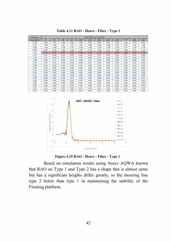
42
Based on simulation results using Ansys AQWA known that RAO on Type 1 and Type 2 has a shape that is almost same but has a significant heights differ greatly, so the mooring line type 2 better than type 1 in maintaining the stability of the Floating platform.
Encounter
Freq (rad/s) 0ᵒ 30ᵒ 60ᵒ 90ᵒ 120ᵒ 150ᵒ 180ᵒ 210ᵒ 240ᵒ 270ᵒ 300ᵒ 330ᵒ
0.189 1.011 1.011 1.010 1.010 1.010 1.011 1.011 1.011 1.010 1.010 1.010 1.011
0.446 1.069 1.068 1.067 1.067 1.067 1.068 1.069 1.068 1.067 1.067 1.067 1.068
0.703 1.249 1.246 1.240 1.237 1.240 1.246 1.249 1.246 1.240 1.237 1.240 1.246
0.959 1.007 1.130 1.358 1.466 1.357 1.129 1.006 1.124 1.350 1.459 1.351 1.125
1.216 6.225 6.341 6.494 6.562 6.493 6.339 6.223 6.272 6.466 6.583 6.467 6.274
1.473 0.517 0.548 0.541 0.531 0.541 0.548 0.517 0.505 0.543 0.577 0.543 0.505
1.730 0.027 0.088 0.033 0.074 0.033 0.088 0.027 0.068 0.036 0.097 0.036 0.068
1.986 0.061 0.071 0.058 0.045 0.058 0.072 0.061 0.050 0.060 0.070 0.060 0.050
2.243 0.031 0.027 0.030 0.032 0.030 0.027 0.031 0.033 0.030 0.026 0.031 0.034
2.500 0.012 0.004 0.012 0.020 0.012 0.004 0.012 0.020 0.012 0.004 0.012 0.020
2.756 0.002 0.005 0.002 0.006 0.002 0.005 0.002 0.006 0.002 0.005 0.002 0.006
3.013 0.003 0.006 0.003 0.004 0.003 0.006 0.003 0.004 0.003 0.006 0.003 0.004
3.270 0.004 0.005 0.004 0.008 0.004 0.005 0.004 0.008 0.004 0.005 0.004 0.008
3.527 0.005 0.003 0.005 0.009 0.005 0.003 0.005 0.009 0.005 0.003 0.005 0.009
3.783 0.005 0.002 0.005 0.011 0.005 0.002 0.005 0.011 0.005 0.002 0.005 0.011
4.040 0.002 0.001 0.002 0.002 0.002 0.001 0.002 0.002 0.002 0.001 0.002 0.002
4.297 0.002 0.002 0.002 0.003 0.002 0.002 0.002 0.003 0.002 0.002 0.002 0.003
4.553 0.002 0.003 0.001 0.003 0.002 0.003 0.001 0.003 0.002 0.003 0.001 0.003
4.810 0.001 0.002 0.001 0.004 0.001 0.002 0.001 0.004 0.001 0.002 0.001 0.004
5.067 0.001 0.001 0.001 0.003 0.001 0.001 0.001 0.003 0.001 0.001 0.001 0.003
Heave RAO, zx0 / z0 (m/m)
Table 4.11 RAO - Heave - Fiber - Type 1
Figure 4.25 RAO - Heave - Fiber - Type 1
43
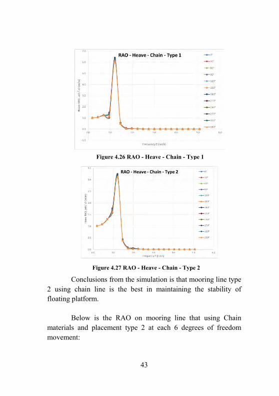
Conclusions from the simulation is that mooring line type 2 using chain line is the best in maintaining the stability of floating platform.
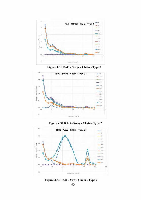
Below is the RAO on mooring line that using Chain materials and placement type 2 at each 6 degrees of freedom movement:
Figure 4.26 RAO - Heave - Chain - Type 1
Figure 4.27 RAO - Heave - Chain - Type 2
44
Figure 4.28 RAO - Heave - Chain - Type 2
Figure 4.29 RAO - Pitch - Chain - Type 2
Figure 4.30 RAO - Roll - Chain - Type 2
45
Figure 4.31 RAO - Surge - Chain - Type 2
Figure 4.32 RAO - Sway - Chain - Type 2
Figure 4.33 RAO - Yaw - Chain - Type 2
46
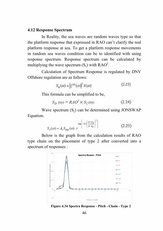
4.12 Response Spectrum In Reality, the sea waves are random waves type so that the platform response that expressed in RAO can’t clarify the real platform response at sea. To get a platform response movements in random sea waves condition can be to identified with using response spectrum. Response spectrum can be calculated by multiplying the wave spectrum (Sζ) with RAO2. Calculation of Spectrum Response is regulated by DNV Offshore regulation are as follows:
This formula can be simplified to be,
Wave spectrum (Sζ) can be determined using JONSWAP Equation.
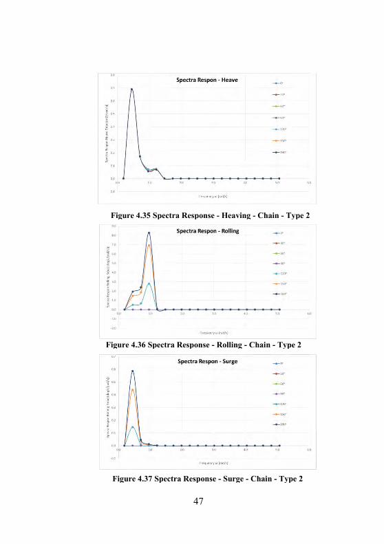
Below is the graph from the calculation results of RAO type chain on the placement of type 2 after converted into a spectrum of responses :
Figure 4.34 Spectra Response - Pitch - Chain - Type 2
47
Figure 4.35 Spectra Response - Heaving - Chain - Type 2
Figure 4.36 Spectra Response - Rolling - Chain - Type 2
Figure 4.37 Spectra Response - Surge - Chain - Type 2
48
From these Graph is known that average heaving movement is 0.685 m, maximum pitching movement is 18o at sea wave coming prom 180 o, And maximum rolling is 8.3o at sea wave coming prom 180 o
4.13 Anchor 4.13.1 Anchor Type
Figure 4.40 Deadweight anchor
Figure 4.38. Spectra Response - Sway - Chain - Type 2
Figure 4.39. Spectra Response - Yaw - Chain - Type 2
49
Type : Deadweight Anchor Consideration : 1. Inexpensive 2. Mooring line connection easily to inspect and service 3. Material for construction readily available and economical 4. Reliable on thin sediment over rock 5. Easy installation (low cost installation) 6. Lateral load resistance is low compared to most anchors except for very hard bottom conditions 7. Large vertical reaction component, permitting shorter mooring line scope
4.13.2 Anchor Shackle Shackle leg diameter is regulated by DNV rules, as shown below:
Based on these formula, Shackle leg diameter is determine about 80.9 mm. Shackle pin diameter is regulated by DNV rules, as shown below:
Based on these formula, Shackle pin diameter is determine about 86.7 mm.
4.13.3 Anchor Pad Eye
Based on Offshore Standart , anchor pad eye is regulated that design load is equals characteristic breaking strength of mooring line. Breking strength od chain is equal 1400 kN, so total load of pad eye must be greater then 1400 Kn.
50
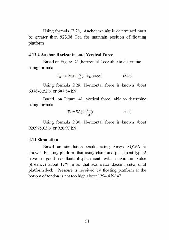
DNV standard regulated that Pad eye Diameter must be greater than Diameter of shackle leg. Diameter of shackle leg is equals 80.9 mm, so Pad eye Diameter is 82 mm 4.13.4 Anchor Weight Weight of deadweight Anchor for tension leg mooring type able to be determined using formula as shown below Where, Tm = Maximum tension Sf = Safety factor σ = Weight per unit volume structure φ = Angle between anchor and mooring line μ = Friction coefficient between anchor and seabed Wσ = Weight per unit volume water Force that acting on connection between mooring line and anchor is shown a figure below
Figure 41 Force distribution that acting on Deadweight Anchor
51
Using formula (2.28), Anchor weight is determined must be greater than 926.08 Ton for maintain position of floating platform
4.13.4 Anchor Horizontal and Vertical Force Based on Figure. 41 ,horizontal force able to determine using formula Using formula 2.29, Horizontal force is known about 607843.52 N or 607.84 kN.
Based on Figure. 41, vertical force able to determine using formula
Using formula 2.30, Horizontal force is known about 920975.03 N or 920.97 kN.
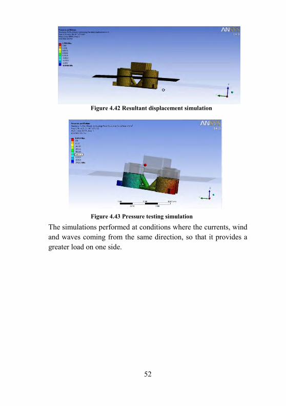
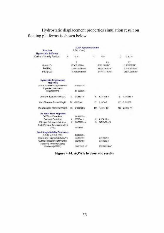
4.14 Simulation Based on simulation results using Ansys AQWA is known Floating platform that using chain and placement type 2 have a good resultant displacement with maximum value (distance) about 1,79 m so that sea water doesn’t enter until platform deck. Pressure is received by floating platform at the bottom of tendon is not too high about 1294.4 N/m2
52
The simulations performed at conditions where the currents, wind and waves coming from the same direction, so that it provides a greater load on one side.
Figure 4.43 Pressure testing simulation
Figure 4.42 Resultant displacement simulation
53
Hydrostatic displacement properties simulation result on floating platforms is shown below
Figure 4.44. AQWA hydrostatic results

Attachment 1
MOORING LINE SPECIFICATION


Attachment 2
RESPONSE AMPLITUDE OPERATOR (RAO)
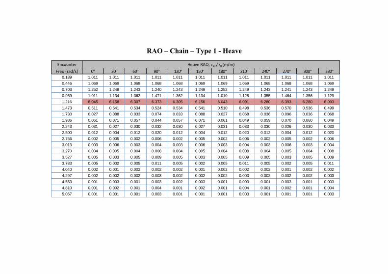
RAO – Chain – Type 1 - Heave
Encounter
Freq (rad/s) 0ᵒ 30ᵒ 60ᵒ 90ᵒ 120ᵒ 150ᵒ 180ᵒ 210ᵒ 240ᵒ 270ᵒ 300ᵒ 330ᵒ
0.189 1.011 1.011 1.011 1.011 1.011 1.011 1.011 1.011 1.011 1.011 1.011 1.011
0.446 1.069 1.069 1.068 1.068 1.068 1.069 1.069 1.069 1.068 1.068 1.068 1.069
0.703 1.252 1.249 1.243 1.240 1.243 1.249 1.252 1.249 1.243 1.241 1.243 1.249
0.959 1.011 1.134 1.362 1.471 1.362 1.134 1.010 1.128 1.355 1.464 1.356 1.129
1.216 6.045 6.158 6.307 6.373 6.305 6.156 6.043 6.091 6.280 6.393 6.280 6.093
1.473 0.511 0.541 0.534 0.524 0.534 0.541 0.510 0.498 0.536 0.570 0.536 0.499
1.730 0.027 0.088 0.033 0.074 0.033 0.088 0.027 0.068 0.036 0.096 0.036 0.068
1.986 0.061 0.071 0.057 0.044 0.057 0.071 0.061 0.049 0.059 0.070 0.060 0.049
2.243 0.031 0.027 0.030 0.032 0.030 0.027 0.031 0.033 0.030 0.026 0.030 0.033
2.500 0.012 0.004 0.012 0.020 0.012 0.004 0.012 0.020 0.012 0.004 0.012 0.020
2.756 0.002 0.005 0.002 0.006 0.002 0.005 0.002 0.006 0.002 0.005 0.002 0.006
3.013 0.003 0.006 0.003 0.004 0.003 0.006 0.003 0.004 0.003 0.006 0.003 0.004
3.270 0.004 0.005 0.004 0.008 0.004 0.005 0.004 0.008 0.004 0.005 0.004 0.008
3.527 0.005 0.003 0.005 0.009 0.005 0.003 0.005 0.009 0.005 0.003 0.005 0.009
3.783 0.005 0.002 0.005 0.011 0.005 0.002 0.005 0.011 0.005 0.002 0.005 0.011
4.040 0.002 0.001 0.002 0.002 0.002 0.001 0.002 0.002 0.002 0.001 0.002 0.002
4.297 0.002 0.002 0.002 0.003 0.002 0.002 0.002 0.003 0.002 0.002 0.002 0.003
4.553 0.001 0.003 0.001 0.003 0.002 0.003 0.001 0.003 0.001 0.003 0.001 0.003
4.810 0.001 0.002 0.001 0.004 0.001 0.002 0.001 0.004 0.001 0.002 0.001 0.004
5.067 0.001 0.001 0.001 0.003 0.001 0.001 0.001 0.003 0.001 0.001 0.001 0.003
Heave RAO, zx0 / z0 (m/m)
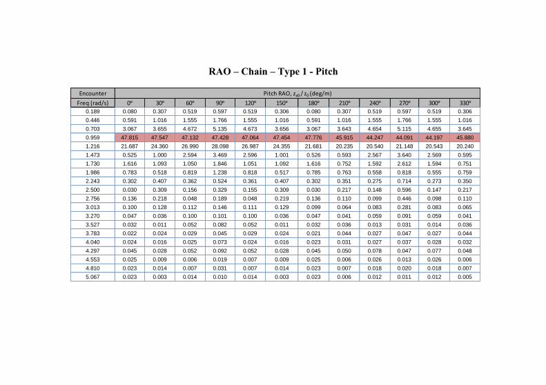
RAO – Chain – Type 1 - Pitch
Encounter
Freq (rad/s) 0ᵒ 30ᵒ 60ᵒ 90ᵒ 120ᵒ 150ᵒ 180ᵒ 210ᵒ 240ᵒ 270ᵒ 300ᵒ 330ᵒ
0.189 0.080 0.307 0.519 0.597 0.519 0.306 0.080 0.307 0.519 0.597 0.519 0.306
0.446 0.591 1.016 1.555 1.766 1.555 1.016 0.591 1.016 1.555 1.766 1.555 1.016
0.703 3.067 3.655 4.672 5.135 4.673 3.656 3.067 3.643 4.654 5.115 4.655 3.645
0.959 47.815 47.547 47.132 47.428 47.064 47.454 47.776 45.915 44.247 44.091 44.197 45.880
1.216 21.687 24.360 26.990 28.098 26.987 24.355 21.681 20.235 20.540 21.148 20.543 20.240
1.473 0.525 1.000 2.594 3.469 2.596 1.001 0.526 0.593 2.567 3.640 2.569 0.595
1.730 1.616 1.093 1.050 1.846 1.051 1.092 1.616 0.752 1.592 2.612 1.594 0.751
1.986 0.783 0.518 0.819 1.238 0.818 0.517 0.785 0.763 0.558 0.818 0.555 0.759
2.243 0.302 0.407 0.362 0.524 0.361 0.407 0.302 0.351 0.275 0.714 0.273 0.350
2.500 0.030 0.309 0.156 0.329 0.155 0.309 0.030 0.217 0.148 0.596 0.147 0.217
2.756 0.136 0.218 0.048 0.189 0.048 0.219 0.136 0.110 0.099 0.446 0.098 0.110
3.013 0.100 0.128 0.112 0.146 0.111 0.129 0.099 0.064 0.083 0.281 0.083 0.065
3.270 0.047 0.036 0.100 0.101 0.100 0.036 0.047 0.041 0.059 0.091 0.059 0.041
3.527 0.032 0.011 0.052 0.082 0.052 0.011 0.032 0.036 0.013 0.031 0.014 0.036
3.783 0.022 0.024 0.029 0.045 0.029 0.024 0.021 0.044 0.027 0.047 0.027 0.044
4.040 0.024 0.016 0.025 0.073 0.024 0.016 0.023 0.031 0.027 0.037 0.028 0.032
4.297 0.045 0.028 0.052 0.092 0.052 0.028 0.045 0.050 0.078 0.047 0.077 0.048
4.553 0.025 0.009 0.006 0.019 0.007 0.009 0.025 0.006 0.026 0.013 0.026 0.006
4.810 0.023 0.014 0.007 0.031 0.007 0.014 0.023 0.007 0.018 0.020 0.018 0.007
5.067 0.023 0.003 0.014 0.010 0.014 0.003 0.023 0.006 0.012 0.011 0.012 0.005
Pitch RAO, zx0 / z0 (deg/m)
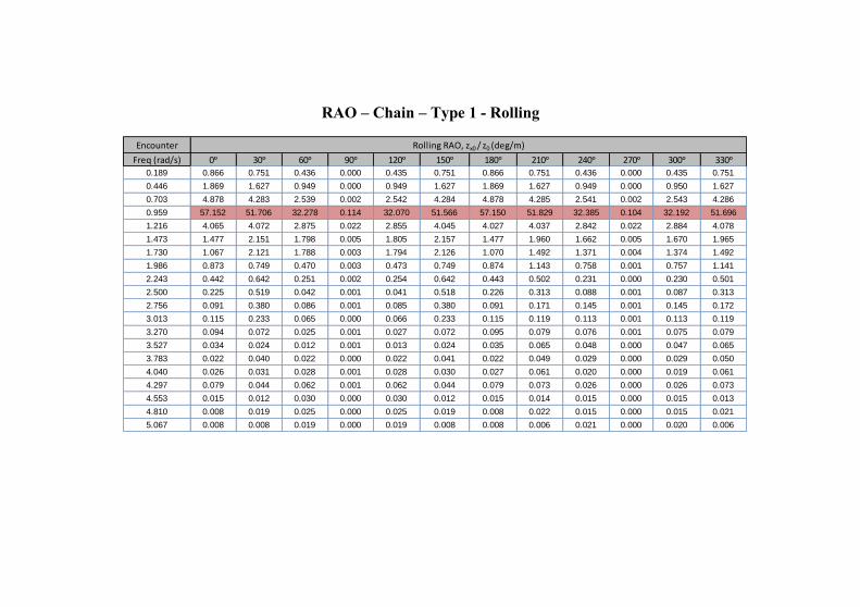
RAO – Chain – Type 1 - Rolling
Encounter
Freq (rad/s) 0ᵒ 30ᵒ 60ᵒ 90ᵒ 120ᵒ 150ᵒ 180ᵒ 210ᵒ 240ᵒ 270ᵒ 300ᵒ 330ᵒ
0.189 0.866 0.751 0.436 0.000 0.435 0.751 0.866 0.751 0.436 0.000 0.435 0.751
0.446 1.869 1.627 0.949 0.000 0.949 1.627 1.869 1.627 0.949 0.000 0.950 1.627
0.703 4.878 4.283 2.539 0.002 2.542 4.284 4.878 4.285 2.541 0.002 2.543 4.286
0.959 57.152 51.706 32.278 0.114 32.070 51.566 57.150 51.829 32.385 0.104 32.192 51.696
1.216 4.065 4.072 2.875 0.022 2.855 4.045 4.027 4.037 2.842 0.022 2.884 4.078
1.473 1.477 2.151 1.798 0.005 1.805 2.157 1.477 1.960 1.662 0.005 1.670 1.965
1.730 1.067 2.121 1.788 0.003 1.794 2.126 1.070 1.492 1.371 0.004 1.374 1.492
1.986 0.873 0.749 0.470 0.003 0.473 0.749 0.874 1.143 0.758 0.001 0.757 1.141
2.243 0.442 0.642 0.251 0.002 0.254 0.642 0.443 0.502 0.231 0.000 0.230 0.501
2.500 0.225 0.519 0.042 0.001 0.041 0.518 0.226 0.313 0.088 0.001 0.087 0.313
2.756 0.091 0.380 0.086 0.001 0.085 0.380 0.091 0.171 0.145 0.001 0.145 0.172
3.013 0.115 0.233 0.065 0.000 0.066 0.233 0.115 0.119 0.113 0.001 0.113 0.119
3.270 0.094 0.072 0.025 0.001 0.027 0.072 0.095 0.079 0.076 0.001 0.075 0.079
3.527 0.034 0.024 0.012 0.001 0.013 0.024 0.035 0.065 0.048 0.000 0.047 0.065
3.783 0.022 0.040 0.022 0.000 0.022 0.041 0.022 0.049 0.029 0.000 0.029 0.050
4.040 0.026 0.031 0.028 0.001 0.028 0.030 0.027 0.061 0.020 0.000 0.019 0.061
4.297 0.079 0.044 0.062 0.001 0.062 0.044 0.079 0.073 0.026 0.000 0.026 0.073
4.553 0.015 0.012 0.030 0.000 0.030 0.012 0.015 0.014 0.015 0.000 0.015 0.013
4.810 0.008 0.019 0.025 0.000 0.025 0.019 0.008 0.022 0.015 0.000 0.015 0.021
5.067 0.008 0.008 0.019 0.000 0.019 0.008 0.008 0.006 0.021 0.000 0.020 0.006
Rolling RAO, zx0 / z0 (deg/m)
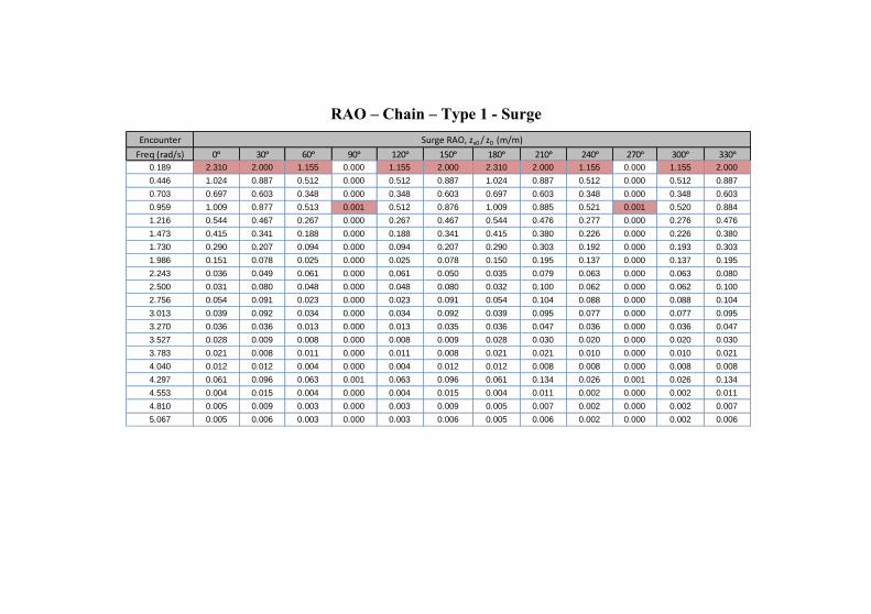
RAO – Chain – Type 1 - Surge
Encounter
Freq (rad/s) 0ᵒ 30ᵒ 60ᵒ 90ᵒ 120ᵒ 150ᵒ 180ᵒ 210ᵒ 240ᵒ 270ᵒ 300ᵒ 330ᵒ
0.189 2.310 2.000 1.155 0.000 1.155 2.000 2.310 2.000 1.155 0.000 1.155 2.000
0.446 1.024 0.887 0.512 0.000 0.512 0.887 1.024 0.887 0.512 0.000 0.512 0.887
0.703 0.697 0.603 0.348 0.000 0.348 0.603 0.697 0.603 0.348 0.000 0.348 0.603
0.959 1.009 0.877 0.513 0.001 0.512 0.876 1.009 0.885 0.521 0.001 0.520 0.884
1.216 0.544 0.467 0.267 0.000 0.267 0.467 0.544 0.476 0.277 0.000 0.276 0.476
1.473 0.415 0.341 0.188 0.000 0.188 0.341 0.415 0.380 0.226 0.000 0.226 0.380
1.730 0.290 0.207 0.094 0.000 0.094 0.207 0.290 0.303 0.192 0.000 0.193 0.303
1.986 0.151 0.078 0.025 0.000 0.025 0.078 0.150 0.195 0.137 0.000 0.137 0.195
2.243 0.036 0.049 0.061 0.000 0.061 0.050 0.035 0.079 0.063 0.000 0.063 0.080
2.500 0.031 0.080 0.048 0.000 0.048 0.080 0.032 0.100 0.062 0.000 0.062 0.100
2.756 0.054 0.091 0.023 0.000 0.023 0.091 0.054 0.104 0.088 0.000 0.088 0.104
3.013 0.039 0.092 0.034 0.000 0.034 0.092 0.039 0.095 0.077 0.000 0.077 0.095
3.270 0.036 0.036 0.013 0.000 0.013 0.035 0.036 0.047 0.036 0.000 0.036 0.047
3.527 0.028 0.009 0.008 0.000 0.008 0.009 0.028 0.030 0.020 0.000 0.020 0.030
3.783 0.021 0.008 0.011 0.000 0.011 0.008 0.021 0.021 0.010 0.000 0.010 0.021
4.040 0.012 0.012 0.004 0.000 0.004 0.012 0.012 0.008 0.008 0.000 0.008 0.008
4.297 0.061 0.096 0.063 0.001 0.063 0.096 0.061 0.134 0.026 0.001 0.026 0.134
4.553 0.004 0.015 0.004 0.000 0.004 0.015 0.004 0.011 0.002 0.000 0.002 0.011
4.810 0.005 0.009 0.003 0.000 0.003 0.009 0.005 0.007 0.002 0.000 0.002 0.007
5.067 0.005 0.006 0.003 0.000 0.003 0.006 0.005 0.006 0.002 0.000 0.002 0.006
Surge RAO, zx0 / z0 (m/m)
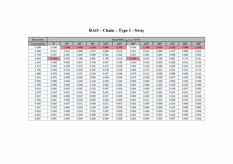
RAO – Chain – Type 1 - Sway
Encounter
Freq (rad/s) 0ᵒ 30ᵒ 60ᵒ 90ᵒ 120ᵒ 150ᵒ 180ᵒ 210ᵒ 240ᵒ 270ᵒ 300ᵒ 330ᵒ
0.189 0.006 1.158 2.005 2.316 2.005 1.158 0.006 1.158 2.005 2.316 2.005 1.158
0.446 0.011 0.513 0.889 1.027 0.889 0.513 0.011 0.513 0.889 1.027 0.889 0.513
0.703 0.031 0.350 0.605 0.698 0.605 0.350 0.031 0.350 0.605 0.698 0.605 0.350
0.959 0.318 0.520 0.786 0.891 0.786 0.519 0.318 0.522 0.780 0.881 0.779 0.521
1.216 0.160 0.430 0.637 0.715 0.637 0.430 0.160 0.134 0.315 0.382 0.315 0.134
1.473 0.045 0.200 0.372 0.441 0.372 0.200 0.045 0.218 0.346 0.392 0.346 0.218
1.730 0.063 0.119 0.278 0.351 0.278 0.119 0.063 0.174 0.221 0.241 0.221 0.174
1.986 0.079 0.046 0.167 0.226 0.167 0.046 0.079 0.112 0.090 0.089 0.090 0.112
2.243 0.070 0.028 0.049 0.093 0.049 0.028 0.070 0.046 0.039 0.057 0.039 0.046
2.500 0.059 0.046 0.049 0.116 0.049 0.046 0.059 0.058 0.035 0.092 0.035 0.058
2.756 0.064 0.053 0.082 0.119 0.082 0.053 0.064 0.060 0.020 0.105 0.019 0.060
3.013 0.065 0.053 0.067 0.110 0.067 0.053 0.064 0.055 0.007 0.106 0.007 0.055
3.270 0.024 0.021 0.041 0.054 0.041 0.021 0.024 0.027 0.022 0.041 0.023 0.027
3.527 0.008 0.005 0.027 0.035 0.027 0.005 0.008 0.018 0.020 0.010 0.020 0.018
3.783 0.001 0.005 0.018 0.025 0.018 0.005 0.001 0.012 0.019 0.009 0.019 0.012
4.040 0.002 0.007 0.011 0.009 0.011 0.007 0.002 0.004 0.009 0.014 0.009 0.005
4.297 0.029 0.060 0.054 0.166 0.054 0.059 0.028 0.083 0.069 0.120 0.069 0.082
4.553 0.003 0.009 0.003 0.013 0.002 0.009 0.003 0.006 0.005 0.018 0.005 0.006
4.810 0.001 0.005 0.004 0.008 0.004 0.005 0.001 0.004 0.005 0.010 0.005 0.004
5.067 0.001 0.004 0.004 0.006 0.004 0.004 0.001 0.003 0.004 0.007 0.004 0.003
Sway RAO, zx0 / z0 (m/m)
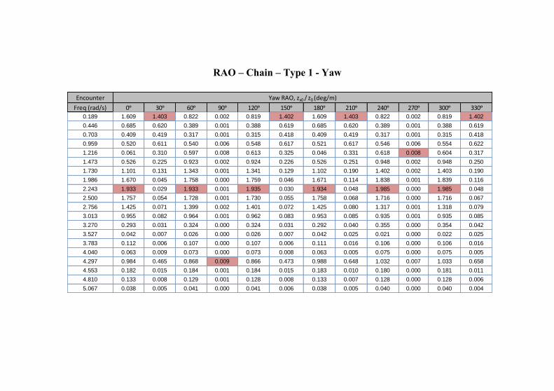
RAO – Chain – Type 1 - Yaw
Encounter
Freq (rad/s) 0ᵒ 30ᵒ 60ᵒ 90ᵒ 120ᵒ 150ᵒ 180ᵒ 210ᵒ 240ᵒ 270ᵒ 300ᵒ 330ᵒ
0.189 1.609 1.403 0.822 0.002 0.819 1.402 1.609 1.403 0.822 0.002 0.819 1.402
0.446 0.685 0.620 0.389 0.001 0.388 0.619 0.685 0.620 0.389 0.001 0.388 0.619
0.703 0.409 0.419 0.317 0.001 0.315 0.418 0.409 0.419 0.317 0.001 0.315 0.418
0.959 0.520 0.611 0.540 0.006 0.548 0.617 0.521 0.617 0.546 0.006 0.554 0.622
1.216 0.061 0.310 0.597 0.008 0.613 0.325 0.046 0.331 0.618 0.008 0.604 0.317
1.473 0.526 0.225 0.923 0.002 0.924 0.226 0.526 0.251 0.948 0.002 0.948 0.250
1.730 1.101 0.131 1.343 0.001 1.341 0.129 1.102 0.190 1.402 0.002 1.403 0.190
1.986 1.670 0.045 1.758 0.000 1.759 0.046 1.671 0.114 1.838 0.001 1.839 0.116
2.243 1.933 0.029 1.933 0.001 1.935 0.030 1.934 0.048 1.985 0.000 1.985 0.048
2.500 1.757 0.054 1.728 0.001 1.730 0.055 1.758 0.068 1.716 0.000 1.716 0.067
2.756 1.425 0.071 1.399 0.002 1.401 0.072 1.425 0.080 1.317 0.001 1.318 0.079
3.013 0.955 0.082 0.964 0.001 0.962 0.083 0.953 0.085 0.935 0.001 0.935 0.085
3.270 0.293 0.031 0.324 0.000 0.324 0.031 0.292 0.040 0.355 0.000 0.354 0.042
3.527 0.042 0.007 0.026 0.000 0.026 0.007 0.042 0.025 0.021 0.000 0.022 0.025
3.783 0.112 0.006 0.107 0.000 0.107 0.006 0.111 0.016 0.106 0.000 0.106 0.016
4.040 0.063 0.009 0.073 0.000 0.073 0.008 0.063 0.005 0.075 0.000 0.075 0.005
4.297 0.984 0.465 0.868 0.009 0.866 0.473 0.988 0.648 1.032 0.007 1.033 0.658
4.553 0.182 0.015 0.184 0.001 0.184 0.015 0.183 0.010 0.180 0.000 0.181 0.011
4.810 0.133 0.008 0.129 0.001 0.128 0.008 0.133 0.007 0.128 0.000 0.128 0.006
5.067 0.038 0.005 0.041 0.000 0.041 0.006 0.038 0.005 0.040 0.000 0.040 0.004
Yaw RAO, zx0 / z0 (deg/m)
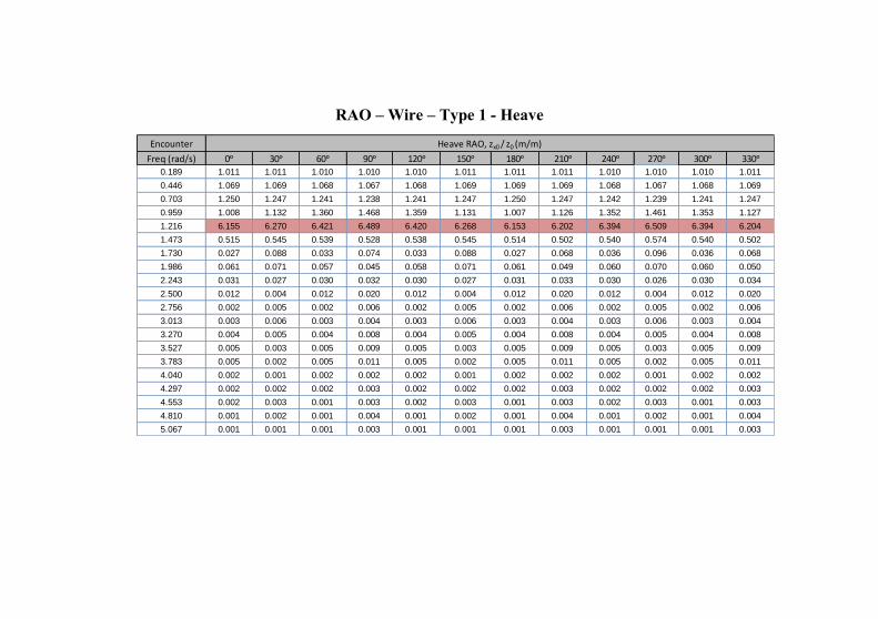
RAO – Wire – Type 1 - Heave
Encounter
Freq (rad/s) 0ᵒ 30ᵒ 60ᵒ 90ᵒ 120ᵒ 150ᵒ 180ᵒ 210ᵒ 240ᵒ 270ᵒ 300ᵒ 330ᵒ
0.189 1.011 1.011 1.010 1.010 1.010 1.011 1.011 1.011 1.010 1.010 1.010 1.011
0.446 1.069 1.069 1.068 1.067 1.068 1.069 1.069 1.069 1.068 1.067 1.068 1.069
0.703 1.250 1.247 1.241 1.238 1.241 1.247 1.250 1.247 1.242 1.239 1.241 1.247
0.959 1.008 1.132 1.360 1.468 1.359 1.131 1.007 1.126 1.352 1.461 1.353 1.127
1.216 6.155 6.270 6.421 6.489 6.420 6.268 6.153 6.202 6.394 6.509 6.394 6.204
1.473 0.515 0.545 0.539 0.528 0.538 0.545 0.514 0.502 0.540 0.574 0.540 0.502
1.730 0.027 0.088 0.033 0.074 0.033 0.088 0.027 0.068 0.036 0.096 0.036 0.068
1.986 0.061 0.071 0.057 0.045 0.058 0.071 0.061 0.049 0.060 0.070 0.060 0.050
2.243 0.031 0.027 0.030 0.032 0.030 0.027 0.031 0.033 0.030 0.026 0.030 0.034
2.500 0.012 0.004 0.012 0.020 0.012 0.004 0.012 0.020 0.012 0.004 0.012 0.020
2.756 0.002 0.005 0.002 0.006 0.002 0.005 0.002 0.006 0.002 0.005 0.002 0.006
3.013 0.003 0.006 0.003 0.004 0.003 0.006 0.003 0.004 0.003 0.006 0.003 0.004
3.270 0.004 0.005 0.004 0.008 0.004 0.005 0.004 0.008 0.004 0.005 0.004 0.008
3.527 0.005 0.003 0.005 0.009 0.005 0.003 0.005 0.009 0.005 0.003 0.005 0.009
3.783 0.005 0.002 0.005 0.011 0.005 0.002 0.005 0.011 0.005 0.002 0.005 0.011
4.040 0.002 0.001 0.002 0.002 0.002 0.001 0.002 0.002 0.002 0.001 0.002 0.002
4.297 0.002 0.002 0.002 0.003 0.002 0.002 0.002 0.003 0.002 0.002 0.002 0.003
4.553 0.002 0.003 0.001 0.003 0.002 0.003 0.001 0.003 0.002 0.003 0.001 0.003
4.810 0.001 0.002 0.001 0.004 0.001 0.002 0.001 0.004 0.001 0.002 0.001 0.004
5.067 0.001 0.001 0.001 0.003 0.001 0.001 0.001 0.003 0.001 0.001 0.001 0.003
Heave RAO, zx0 / z0 (m/m)
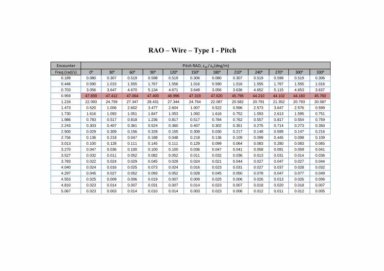
RAO – Wire – Type 1 - Pitch
Encounter
Freq (rad/s) 0ᵒ 30ᵒ 60ᵒ 90ᵒ 120ᵒ 150ᵒ 180ᵒ 210ᵒ 240ᵒ 270ᵒ 300ᵒ 330ᵒ
0.189 0.080 0.307 0.519 0.598 0.519 0.306 0.080 0.307 0.519 0.598 0.519 0.306
0.446 0.590 1.015 1.555 1.767 1.556 1.016 0.590 1.016 1.555 1.767 1.555 1.016
0.703 3.056 3.647 4.670 5.134 4.671 3.649 3.056 3.636 4.652 5.115 4.653 3.637
0.959 47.659 47.412 47.064 47.400 46.996 47.319 47.620 45.796 44.210 44.102 44.160 45.760
1.216 22.093 24.759 27.347 28.431 27.344 24.754 22.087 20.582 20.791 21.352 20.793 20.587
1.473 0.520 1.006 2.602 3.477 2.604 1.007 0.522 0.596 2.573 3.647 2.576 0.599
1.730 1.616 1.093 1.051 1.847 1.053 1.092 1.616 0.752 1.593 2.613 1.595 0.751
1.986 0.783 0.517 0.818 1.236 0.817 0.517 0.784 0.762 0.557 0.817 0.554 0.759
2.243 0.303 0.407 0.361 0.524 0.360 0.407 0.302 0.351 0.275 0.714 0.273 0.350
2.500 0.029 0.309 0.156 0.328 0.155 0.309 0.030 0.217 0.148 0.595 0.147 0.216
2.756 0.136 0.218 0.047 0.188 0.048 0.218 0.136 0.109 0.099 0.445 0.098 0.109
3.013 0.100 0.128 0.111 0.145 0.111 0.129 0.099 0.064 0.083 0.280 0.083 0.065
3.270 0.047 0.036 0.100 0.100 0.100 0.036 0.047 0.041 0.058 0.091 0.059 0.041
3.527 0.032 0.011 0.052 0.082 0.052 0.011 0.032 0.036 0.013 0.031 0.014 0.036
3.783 0.022 0.024 0.029 0.045 0.029 0.024 0.021 0.044 0.027 0.047 0.027 0.044
4.040 0.024 0.016 0.025 0.073 0.024 0.016 0.023 0.031 0.027 0.037 0.028 0.032
4.297 0.045 0.027 0.052 0.093 0.052 0.028 0.045 0.050 0.078 0.047 0.077 0.049
4.553 0.025 0.009 0.006 0.019 0.007 0.009 0.025 0.006 0.026 0.013 0.026 0.006
4.810 0.023 0.014 0.007 0.031 0.007 0.014 0.023 0.007 0.018 0.020 0.018 0.007
5.067 0.023 0.003 0.014 0.010 0.014 0.003 0.023 0.006 0.012 0.011 0.012 0.005
Pitch RAO, zx0 / z0 (deg/m)
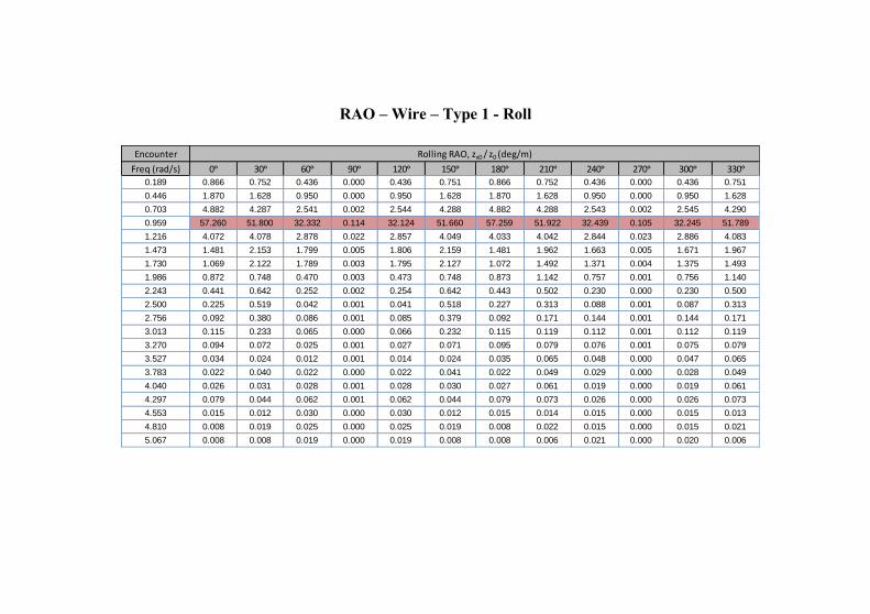
RAO – Wire – Type 1 - Roll
Encounter
Freq (rad/s) 0ᵒ 30ᵒ 60ᵒ 90ᵒ 120ᵒ 150ᵒ 180ᵒ 210ᵒ 240ᵒ 270ᵒ 300ᵒ 330ᵒ
0.189 0.866 0.752 0.436 0.000 0.436 0.751 0.866 0.752 0.436 0.000 0.436 0.751
0.446 1.870 1.628 0.950 0.000 0.950 1.628 1.870 1.628 0.950 0.000 0.950 1.628
0.703 4.882 4.287 2.541 0.002 2.544 4.288 4.882 4.288 2.543 0.002 2.545 4.290
0.959 57.260 51.800 32.332 0.114 32.124 51.660 57.259 51.922 32.439 0.105 32.245 51.789
1.216 4.072 4.078 2.878 0.022 2.857 4.049 4.033 4.042 2.844 0.023 2.886 4.083
1.473 1.481 2.153 1.799 0.005 1.806 2.159 1.481 1.962 1.663 0.005 1.671 1.967
1.730 1.069 2.122 1.789 0.003 1.795 2.127 1.072 1.492 1.371 0.004 1.375 1.493
1.986 0.872 0.748 0.470 0.003 0.473 0.748 0.873 1.142 0.757 0.001 0.756 1.140
2.243 0.441 0.642 0.252 0.002 0.254 0.642 0.443 0.502 0.230 0.000 0.230 0.500
2.500 0.225 0.519 0.042 0.001 0.041 0.518 0.227 0.313 0.088 0.001 0.087 0.313
2.756 0.092 0.380 0.086 0.001 0.085 0.379 0.092 0.171 0.144 0.001 0.144 0.171
3.013 0.115 0.233 0.065 0.000 0.066 0.232 0.115 0.119 0.112 0.001 0.112 0.119
3.270 0.094 0.072 0.025 0.001 0.027 0.071 0.095 0.079 0.076 0.001 0.075 0.079
3.527 0.034 0.024 0.012 0.001 0.014 0.024 0.035 0.065 0.048 0.000 0.047 0.065
3.783 0.022 0.040 0.022 0.000 0.022 0.041 0.022 0.049 0.029 0.000 0.028 0.049
4.040 0.026 0.031 0.028 0.001 0.028 0.030 0.027 0.061 0.019 0.000 0.019 0.061
4.297 0.079 0.044 0.062 0.001 0.062 0.044 0.079 0.073 0.026 0.000 0.026 0.073
4.553 0.015 0.012 0.030 0.000 0.030 0.012 0.015 0.014 0.015 0.000 0.015 0.013
4.810 0.008 0.019 0.025 0.000 0.025 0.019 0.008 0.022 0.015 0.000 0.015 0.021
5.067 0.008 0.008 0.019 0.000 0.019 0.008 0.008 0.006 0.021 0.000 0.020 0.006
Rolling RAO, zx0 / z0 (deg/m)
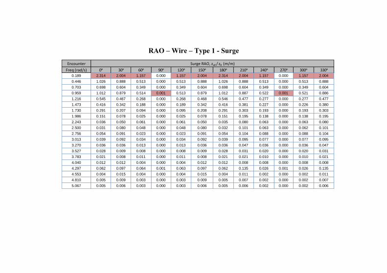
RAO – Wire – Type 1 - Surge
Encounter
Freq (rad/s) 0ᵒ 30ᵒ 60ᵒ 90ᵒ 120ᵒ 150ᵒ 180ᵒ 210ᵒ 240ᵒ 270ᵒ 300ᵒ 330ᵒ
0.189 2.314 2.004 1.157 0.000 1.157 2.004 2.314 2.004 1.157 0.000 1.157 2.004
0.446 1.026 0.888 0.513 0.000 0.513 0.888 1.026 0.888 0.513 0.000 0.513 0.888
0.703 0.698 0.604 0.349 0.000 0.349 0.604 0.698 0.604 0.349 0.000 0.349 0.604
0.959 1.012 0.879 0.514 0.001 0.513 0.879 1.012 0.887 0.522 0.001 0.521 0.886
1.216 0.545 0.467 0.268 0.000 0.268 0.468 0.546 0.477 0.277 0.000 0.277 0.477
1.473 0.416 0.342 0.188 0.000 0.189 0.342 0.416 0.381 0.227 0.000 0.226 0.380
1.730 0.291 0.207 0.094 0.000 0.095 0.208 0.291 0.303 0.193 0.000 0.193 0.303
1.986 0.151 0.078 0.025 0.000 0.025 0.078 0.151 0.195 0.138 0.000 0.138 0.195
2.243 0.036 0.050 0.061 0.000 0.061 0.050 0.035 0.080 0.063 0.000 0.063 0.080
2.500 0.031 0.080 0.048 0.000 0.048 0.080 0.032 0.101 0.063 0.000 0.062 0.101
2.756 0.054 0.091 0.023 0.000 0.023 0.091 0.054 0.104 0.088 0.000 0.088 0.104
3.013 0.039 0.092 0.034 0.000 0.034 0.092 0.039 0.095 0.077 0.000 0.077 0.095
3.270 0.036 0.036 0.013 0.000 0.013 0.036 0.036 0.047 0.036 0.000 0.036 0.047
3.527 0.028 0.009 0.008 0.000 0.008 0.009 0.028 0.031 0.020 0.000 0.020 0.031
3.783 0.021 0.008 0.011 0.000 0.011 0.008 0.021 0.021 0.010 0.000 0.010 0.021
4.040 0.012 0.012 0.004 0.000 0.004 0.012 0.012 0.008 0.008 0.000 0.008 0.008
4.297 0.062 0.097 0.064 0.001 0.063 0.097 0.062 0.135 0.026 0.001 0.026 0.135
4.553 0.004 0.015 0.004 0.000 0.004 0.015 0.004 0.011 0.002 0.000 0.002 0.011
4.810 0.005 0.009 0.003 0.000 0.003 0.009 0.005 0.007 0.002 0.000 0.002 0.007
5.067 0.005 0.006 0.003 0.000 0.003 0.006 0.005 0.006 0.002 0.000 0.002 0.006
Surge RAO, zx0 / z0 (m/m)
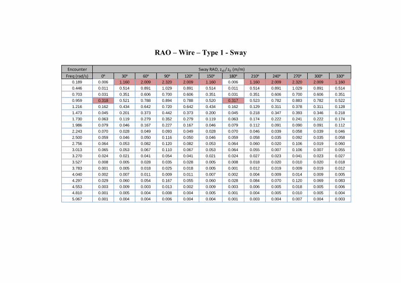
RAO – Wire – Type 1 - Sway
Encounter
Freq (rad/s) 0ᵒ 30ᵒ 60ᵒ 90ᵒ 120ᵒ 150ᵒ 180ᵒ 210ᵒ 240ᵒ 270ᵒ 300ᵒ 330ᵒ
0.189 0.006 1.160 2.009 2.320 2.009 1.160 0.006 1.160 2.009 2.320 2.009 1.160
0.446 0.011 0.514 0.891 1.029 0.891 0.514 0.011 0.514 0.891 1.029 0.891 0.514
0.703 0.031 0.351 0.606 0.700 0.606 0.351 0.031 0.351 0.606 0.700 0.606 0.351
0.959 0.318 0.521 0.788 0.894 0.788 0.520 0.317 0.523 0.782 0.883 0.782 0.522
1.216 0.162 0.434 0.642 0.720 0.642 0.434 0.162 0.129 0.311 0.378 0.311 0.128
1.473 0.045 0.201 0.373 0.442 0.373 0.200 0.045 0.218 0.347 0.393 0.346 0.218
1.730 0.063 0.119 0.279 0.352 0.279 0.119 0.063 0.174 0.222 0.241 0.222 0.174
1.986 0.079 0.046 0.167 0.227 0.167 0.046 0.079 0.112 0.091 0.090 0.091 0.112
2.243 0.070 0.028 0.049 0.093 0.049 0.028 0.070 0.046 0.039 0.058 0.039 0.046
2.500 0.059 0.046 0.050 0.116 0.050 0.046 0.059 0.058 0.035 0.092 0.035 0.058
2.756 0.064 0.053 0.082 0.120 0.082 0.053 0.064 0.060 0.020 0.106 0.019 0.060
3.013 0.065 0.053 0.067 0.110 0.067 0.053 0.064 0.055 0.007 0.106 0.007 0.055
3.270 0.024 0.021 0.041 0.054 0.041 0.021 0.024 0.027 0.023 0.041 0.023 0.027
3.527 0.008 0.005 0.028 0.035 0.028 0.005 0.008 0.018 0.020 0.010 0.020 0.018
3.783 0.001 0.005 0.018 0.025 0.018 0.005 0.001 0.012 0.019 0.009 0.019 0.012
4.040 0.002 0.007 0.011 0.009 0.011 0.007 0.002 0.004 0.009 0.014 0.009 0.005
4.297 0.029 0.060 0.054 0.167 0.055 0.060 0.028 0.084 0.070 0.120 0.069 0.083
4.553 0.003 0.009 0.003 0.013 0.002 0.009 0.003 0.006 0.005 0.018 0.005 0.006
4.810 0.001 0.005 0.004 0.008 0.004 0.005 0.001 0.004 0.005 0.010 0.005 0.004
5.067 0.001 0.004 0.004 0.006 0.004 0.004 0.001 0.003 0.004 0.007 0.004 0.003
Sway RAO, zx0 / z0 (m/m)
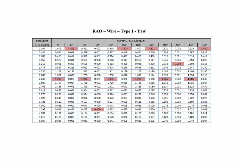
RAO – Wire – Type 1 - Yaw
Encounter
Freq (rad/s) 0ᵒ 30ᵒ 60ᵒ 90ᵒ 120ᵒ 150ᵒ 180ᵒ 210ᵒ 240ᵒ 270ᵒ 300ᵒ 330ᵒ
0.189 1.607 1.401 0.821 0.002 0.818 1.400 1.607 1.401 0.821 0.002 0.818 1.400
0.446 0.684 0.619 0.389 0.001 0.387 0.618 0.684 0.619 0.389 0.001 0.387 0.618
0.703 0.408 0.419 0.316 0.001 0.314 0.417 0.408 0.419 0.316 0.001 0.314 0.417
0.959 0.520 0.611 0.539 0.006 0.548 0.617 0.520 0.617 0.546 0.006 0.553 0.622
1.216 0.061 0.309 0.596 0.009 0.613 0.325 0.046 0.330 0.618 0.008 0.603 0.316
1.473 0.527 0.225 0.923 0.002 0.924 0.225 0.526 0.251 0.948 0.002 0.947 0.250
1.730 1.101 0.131 1.343 0.001 1.341 0.129 1.102 0.190 1.402 0.002 1.403 0.190
1.986 1.671 0.045 1.758 0.000 1.758 0.046 1.671 0.114 1.838 0.001 1.839 0.115
2.243 1.933 0.029 1.933 0.001 1.935 0.030 1.934 0.048 1.985 0.000 1.985 0.048
2.500 1.757 0.054 1.728 0.001 1.730 0.055 1.758 0.068 1.716 0.000 1.716 0.067
2.756 1.425 0.071 1.399 0.002 1.401 0.072 1.425 0.080 1.317 0.001 1.318 0.079
3.013 0.955 0.082 0.964 0.001 0.962 0.083 0.953 0.085 0.935 0.001 0.935 0.085
3.270 0.293 0.031 0.324 0.000 0.324 0.031 0.292 0.040 0.355 0.000 0.354 0.042
3.527 0.042 0.007 0.026 0.000 0.026 0.007 0.042 0.025 0.021 0.000 0.022 0.025
3.783 0.112 0.006 0.107 0.000 0.107 0.006 0.111 0.016 0.106 0.000 0.106 0.016
4.040 0.063 0.009 0.073 0.000 0.073 0.008 0.063 0.005 0.075 0.000 0.075 0.005
4.297 0.986 0.467 0.865 0.009 0.863 0.475 0.991 0.650 1.031 0.007 1.032 0.661
4.553 0.182 0.015 0.184 0.001 0.184 0.015 0.183 0.010 0.180 0.000 0.181 0.011
4.810 0.133 0.008 0.129 0.001 0.128 0.008 0.133 0.007 0.128 0.000 0.128 0.006
5.067 0.038 0.005 0.041 0.000 0.041 0.006 0.038 0.005 0.040 0.000 0.040 0.004
Yaw RAO, zx0 / z0 (deg/m)
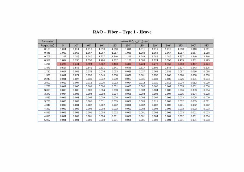
RAO – Fiber – Type 1 - Heave
Encounter
Freq (rad/s) 0ᵒ 30ᵒ 60ᵒ 90ᵒ 120ᵒ 150ᵒ 180ᵒ 210ᵒ 240ᵒ 270ᵒ 300ᵒ 330ᵒ
0.189 1.011 1.011 1.010 1.010 1.010 1.011 1.011 1.011 1.010 1.010 1.010 1.011
0.446 1.069 1.068 1.067 1.067 1.067 1.068 1.069 1.068 1.067 1.067 1.067 1.068
0.703 1.249 1.246 1.240 1.237 1.240 1.246 1.249 1.246 1.240 1.237 1.240 1.246
0.959 1.007 1.130 1.358 1.466 1.357 1.129 1.006 1.124 1.350 1.459 1.351 1.125
1.216 6.225 6.341 6.494 6.562 6.493 6.339 6.223 6.272 6.466 6.583 6.467 6.274
1.473 0.517 0.548 0.541 0.531 0.541 0.548 0.517 0.505 0.543 0.577 0.543 0.505
1.730 0.027 0.088 0.033 0.074 0.033 0.088 0.027 0.068 0.036 0.097 0.036 0.068
1.986 0.061 0.071 0.058 0.045 0.058 0.072 0.061 0.050 0.060 0.070 0.060 0.050
2.243 0.031 0.027 0.030 0.032 0.030 0.027 0.031 0.033 0.030 0.026 0.031 0.034
2.500 0.012 0.004 0.012 0.020 0.012 0.004 0.012 0.020 0.012 0.004 0.012 0.020
2.756 0.002 0.005 0.002 0.006 0.002 0.005 0.002 0.006 0.002 0.005 0.002 0.006
3.013 0.003 0.006 0.003 0.004 0.003 0.006 0.003 0.004 0.003 0.006 0.003 0.004
3.270 0.004 0.005 0.004 0.008 0.004 0.005 0.004 0.008 0.004 0.005 0.004 0.008
3.527 0.005 0.003 0.005 0.009 0.005 0.003 0.005 0.009 0.005 0.003 0.005 0.009
3.783 0.005 0.002 0.005 0.011 0.005 0.002 0.005 0.011 0.005 0.002 0.005 0.011
4.040 0.002 0.001 0.002 0.002 0.002 0.001 0.002 0.002 0.002 0.001 0.002 0.002
4.297 0.002 0.002 0.002 0.003 0.002 0.002 0.002 0.003 0.002 0.002 0.002 0.003
4.553 0.002 0.003 0.001 0.003 0.002 0.003 0.001 0.003 0.002 0.003 0.001 0.003
4.810 0.001 0.002 0.001 0.004 0.001 0.002 0.001 0.004 0.001 0.002 0.001 0.004
5.067 0.001 0.001 0.001 0.003 0.001 0.001 0.001 0.003 0.001 0.001 0.001 0.003
Heave RAO, zx0 / z0 (m/m)
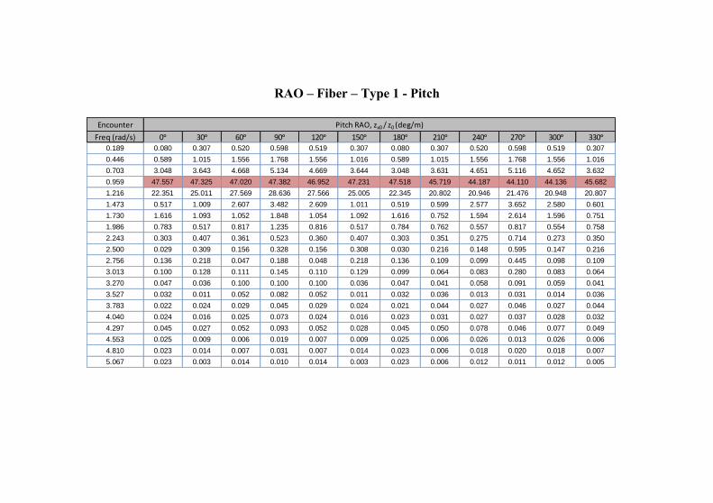
RAO – Fiber – Type 1 - Pitch
Encounter
Freq (rad/s) 0ᵒ 30ᵒ 60ᵒ 90ᵒ 120ᵒ 150ᵒ 180ᵒ 210ᵒ 240ᵒ 270ᵒ 300ᵒ 330ᵒ
0.189 0.080 0.307 0.520 0.598 0.519 0.307 0.080 0.307 0.520 0.598 0.519 0.307
0.446 0.589 1.015 1.556 1.768 1.556 1.016 0.589 1.015 1.556 1.768 1.556 1.016
0.703 3.048 3.643 4.668 5.134 4.669 3.644 3.048 3.631 4.651 5.116 4.652 3.632
0.959 47.557 47.325 47.020 47.382 46.952 47.231 47.518 45.719 44.187 44.110 44.136 45.682
1.216 22.351 25.011 27.569 28.636 27.566 25.005 22.345 20.802 20.946 21.476 20.948 20.807
1.473 0.517 1.009 2.607 3.482 2.609 1.011 0.519 0.599 2.577 3.652 2.580 0.601
1.730 1.616 1.093 1.052 1.848 1.054 1.092 1.616 0.752 1.594 2.614 1.596 0.751
1.986 0.783 0.517 0.817 1.235 0.816 0.517 0.784 0.762 0.557 0.817 0.554 0.758
2.243 0.303 0.407 0.361 0.523 0.360 0.407 0.303 0.351 0.275 0.714 0.273 0.350
2.500 0.029 0.309 0.156 0.328 0.156 0.308 0.030 0.216 0.148 0.595 0.147 0.216
2.756 0.136 0.218 0.047 0.188 0.048 0.218 0.136 0.109 0.099 0.445 0.098 0.109
3.013 0.100 0.128 0.111 0.145 0.110 0.129 0.099 0.064 0.083 0.280 0.083 0.064
3.270 0.047 0.036 0.100 0.100 0.100 0.036 0.047 0.041 0.058 0.091 0.059 0.041
3.527 0.032 0.011 0.052 0.082 0.052 0.011 0.032 0.036 0.013 0.031 0.014 0.036
3.783 0.022 0.024 0.029 0.045 0.029 0.024 0.021 0.044 0.027 0.046 0.027 0.044
4.040 0.024 0.016 0.025 0.073 0.024 0.016 0.023 0.031 0.027 0.037 0.028 0.032
4.297 0.045 0.027 0.052 0.093 0.052 0.028 0.045 0.050 0.078 0.046 0.077 0.049
4.553 0.025 0.009 0.006 0.019 0.007 0.009 0.025 0.006 0.026 0.013 0.026 0.006
4.810 0.023 0.014 0.007 0.031 0.007 0.014 0.023 0.006 0.018 0.020 0.018 0.007
5.067 0.023 0.003 0.014 0.010 0.014 0.003 0.023 0.006 0.012 0.011 0.012 0.005
Pitch RAO, zx0 / z0 (deg/m)
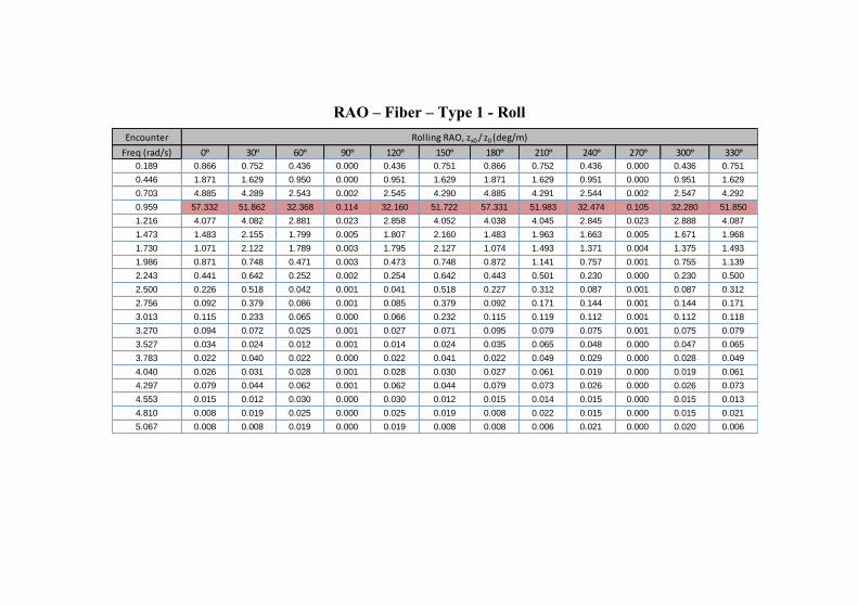
RAO – Fiber – Type 1 - Roll
Encounter
Freq (rad/s) 0ᵒ 30ᵒ 60ᵒ 90ᵒ 120ᵒ 150ᵒ 180ᵒ 210ᵒ 240ᵒ 270ᵒ 300ᵒ 330ᵒ
0.189 0.866 0.752 0.436 0.000 0.436 0.751 0.866 0.752 0.436 0.000 0.436 0.751
0.446 1.871 1.629 0.950 0.000 0.951 1.629 1.871 1.629 0.951 0.000 0.951 1.629
0.703 4.885 4.289 2.543 0.002 2.545 4.290 4.885 4.291 2.544 0.002 2.547 4.292
0.959 57.332 51.862 32.368 0.114 32.160 51.722 57.331 51.983 32.474 0.105 32.280 51.850
1.216 4.077 4.082 2.881 0.023 2.858 4.052 4.038 4.045 2.845 0.023 2.888 4.087
1.473 1.483 2.155 1.799 0.005 1.807 2.160 1.483 1.963 1.663 0.005 1.671 1.968
1.730 1.071 2.122 1.789 0.003 1.795 2.127 1.074 1.493 1.371 0.004 1.375 1.493
1.986 0.871 0.748 0.471 0.003 0.473 0.748 0.872 1.141 0.757 0.001 0.755 1.139
2.243 0.441 0.642 0.252 0.002 0.254 0.642 0.443 0.501 0.230 0.000 0.230 0.500
2.500 0.226 0.518 0.042 0.001 0.041 0.518 0.227 0.312 0.087 0.001 0.087 0.312
2.756 0.092 0.379 0.086 0.001 0.085 0.379 0.092 0.171 0.144 0.001 0.144 0.171
3.013 0.115 0.233 0.065 0.000 0.066 0.232 0.115 0.119 0.112 0.001 0.112 0.118
3.270 0.094 0.072 0.025 0.001 0.027 0.071 0.095 0.079 0.075 0.001 0.075 0.079
3.527 0.034 0.024 0.012 0.001 0.014 0.024 0.035 0.065 0.048 0.000 0.047 0.065
3.783 0.022 0.040 0.022 0.000 0.022 0.041 0.022 0.049 0.029 0.000 0.028 0.049
4.040 0.026 0.031 0.028 0.001 0.028 0.030 0.027 0.061 0.019 0.000 0.019 0.061
4.297 0.079 0.044 0.062 0.001 0.062 0.044 0.079 0.073 0.026 0.000 0.026 0.073
4.553 0.015 0.012 0.030 0.000 0.030 0.012 0.015 0.014 0.015 0.000 0.015 0.013
4.810 0.008 0.019 0.025 0.000 0.025 0.019 0.008 0.022 0.015 0.000 0.015 0.021
5.067 0.008 0.008 0.019 0.000 0.019 0.008 0.008 0.006 0.021 0.000 0.020 0.006
Rolling RAO, zx0 / z0 (deg/m)
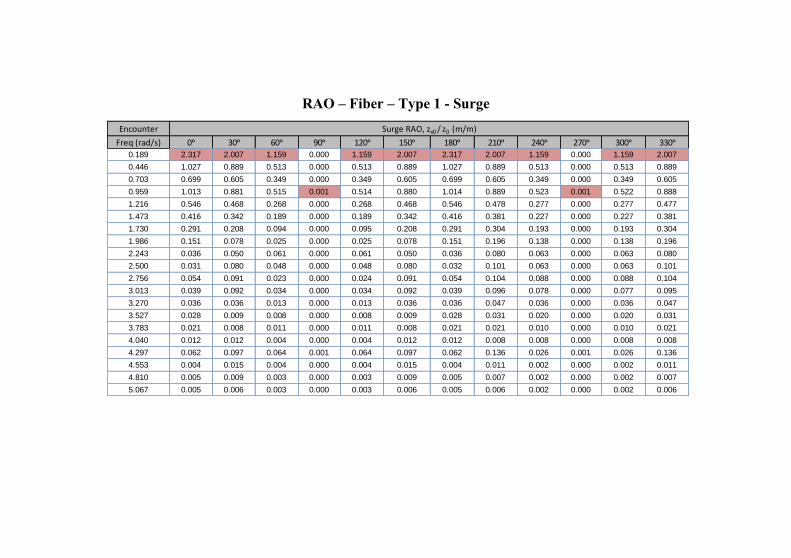
RAO – Fiber – Type 1 - Surge
Encounter
Freq (rad/s) 0ᵒ 30ᵒ 60ᵒ 90ᵒ 120ᵒ 150ᵒ 180ᵒ 210ᵒ 240ᵒ 270ᵒ 300ᵒ 330ᵒ
0.189 2.317 2.007 1.159 0.000 1.159 2.007 2.317 2.007 1.159 0.000 1.159 2.007
0.446 1.027 0.889 0.513 0.000 0.513 0.889 1.027 0.889 0.513 0.000 0.513 0.889
0.703 0.699 0.605 0.349 0.000 0.349 0.605 0.699 0.605 0.349 0.000 0.349 0.605
0.959 1.013 0.881 0.515 0.001 0.514 0.880 1.014 0.889 0.523 0.001 0.522 0.888
1.216 0.546 0.468 0.268 0.000 0.268 0.468 0.546 0.478 0.277 0.000 0.277 0.477
1.473 0.416 0.342 0.189 0.000 0.189 0.342 0.416 0.381 0.227 0.000 0.227 0.381
1.730 0.291 0.208 0.094 0.000 0.095 0.208 0.291 0.304 0.193 0.000 0.193 0.304
1.986 0.151 0.078 0.025 0.000 0.025 0.078 0.151 0.196 0.138 0.000 0.138 0.196
2.243 0.036 0.050 0.061 0.000 0.061 0.050 0.036 0.080 0.063 0.000 0.063 0.080
2.500 0.031 0.080 0.048 0.000 0.048 0.080 0.032 0.101 0.063 0.000 0.063 0.101
2.756 0.054 0.091 0.023 0.000 0.024 0.091 0.054 0.104 0.088 0.000 0.088 0.104
3.013 0.039 0.092 0.034 0.000 0.034 0.092 0.039 0.096 0.078 0.000 0.077 0.095
3.270 0.036 0.036 0.013 0.000 0.013 0.036 0.036 0.047 0.036 0.000 0.036 0.047
3.527 0.028 0.009 0.008 0.000 0.008 0.009 0.028 0.031 0.020 0.000 0.020 0.031
3.783 0.021 0.008 0.011 0.000 0.011 0.008 0.021 0.021 0.010 0.000 0.010 0.021
4.040 0.012 0.012 0.004 0.000 0.004 0.012 0.012 0.008 0.008 0.000 0.008 0.008
4.297 0.062 0.097 0.064 0.001 0.064 0.097 0.062 0.136 0.026 0.001 0.026 0.136
4.553 0.004 0.015 0.004 0.000 0.004 0.015 0.004 0.011 0.002 0.000 0.002 0.011
4.810 0.005 0.009 0.003 0.000 0.003 0.009 0.005 0.007 0.002 0.000 0.002 0.007
5.067 0.005 0.006 0.003 0.000 0.003 0.006 0.005 0.006 0.002 0.000 0.002 0.006
Surge RAO, zx0 / z0 (m/m)
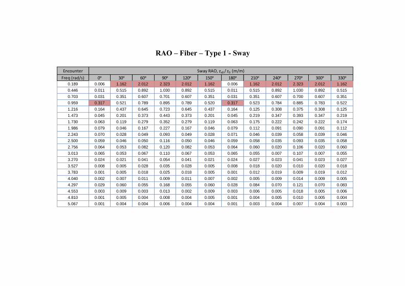
RAO – Fiber – Type 1 - Sway
Encounter
Freq (rad/s) 0ᵒ 30ᵒ 60ᵒ 90ᵒ 120ᵒ 150ᵒ 180ᵒ 210ᵒ 240ᵒ 270ᵒ 300ᵒ 330ᵒ
0.189 0.006 1.162 2.012 2.323 2.012 1.162 0.006 1.162 2.012 2.323 2.012 1.162
0.446 0.011 0.515 0.892 1.030 0.892 0.515 0.011 0.515 0.892 1.030 0.892 0.515
0.703 0.031 0.351 0.607 0.701 0.607 0.351 0.031 0.351 0.607 0.700 0.607 0.351
0.959 0.317 0.521 0.789 0.895 0.789 0.520 0.317 0.523 0.784 0.885 0.783 0.522
1.216 0.164 0.437 0.645 0.723 0.645 0.437 0.164 0.125 0.308 0.375 0.308 0.125
1.473 0.045 0.201 0.373 0.443 0.373 0.201 0.045 0.219 0.347 0.393 0.347 0.219
1.730 0.063 0.119 0.279 0.352 0.279 0.119 0.063 0.175 0.222 0.242 0.222 0.174
1.986 0.079 0.046 0.167 0.227 0.167 0.046 0.079 0.112 0.091 0.090 0.091 0.112
2.243 0.070 0.028 0.049 0.093 0.049 0.028 0.071 0.046 0.039 0.058 0.039 0.046
2.500 0.059 0.046 0.050 0.116 0.050 0.046 0.059 0.058 0.035 0.093 0.035 0.058
2.756 0.064 0.053 0.082 0.120 0.082 0.053 0.064 0.060 0.020 0.106 0.020 0.060
3.013 0.065 0.053 0.067 0.110 0.067 0.053 0.065 0.055 0.007 0.107 0.007 0.055
3.270 0.024 0.021 0.041 0.054 0.041 0.021 0.024 0.027 0.023 0.041 0.023 0.027
3.527 0.008 0.005 0.028 0.035 0.028 0.005 0.008 0.018 0.020 0.010 0.020 0.018
3.783 0.001 0.005 0.018 0.025 0.018 0.005 0.001 0.012 0.019 0.009 0.019 0.012
4.040 0.002 0.007 0.011 0.009 0.011 0.007 0.002 0.005 0.009 0.014 0.009 0.005
4.297 0.029 0.060 0.055 0.168 0.055 0.060 0.028 0.084 0.070 0.121 0.070 0.083
4.553 0.003 0.009 0.003 0.013 0.002 0.009 0.003 0.006 0.005 0.018 0.005 0.006
4.810 0.001 0.005 0.004 0.008 0.004 0.005 0.001 0.004 0.005 0.010 0.005 0.004
5.067 0.001 0.004 0.004 0.006 0.004 0.004 0.001 0.003 0.004 0.007 0.004 0.003
Sway RAO, zx0 / z0 (m/m)
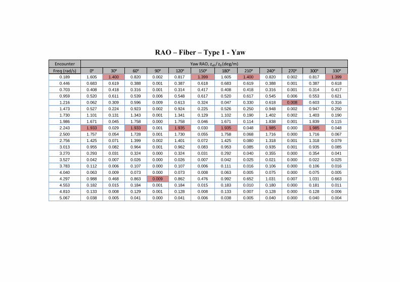
RAO – Fiber – Type 1 - Yaw
Encounter
Freq (rad/s) 0ᵒ 30ᵒ 60ᵒ 90ᵒ 120ᵒ 150ᵒ 180ᵒ 210ᵒ 240ᵒ 270ᵒ 300ᵒ 330ᵒ
0.189 1.605 1.400 0.820 0.002 0.817 1.399 1.605 1.400 0.820 0.002 0.817 1.399
0.446 0.683 0.619 0.388 0.001 0.387 0.618 0.683 0.619 0.388 0.001 0.387 0.618
0.703 0.408 0.418 0.316 0.001 0.314 0.417 0.408 0.418 0.316 0.001 0.314 0.417
0.959 0.520 0.611 0.539 0.006 0.548 0.617 0.520 0.617 0.545 0.006 0.553 0.621
1.216 0.062 0.309 0.596 0.009 0.613 0.324 0.047 0.330 0.618 0.008 0.603 0.316
1.473 0.527 0.224 0.923 0.002 0.924 0.225 0.526 0.250 0.948 0.002 0.947 0.250
1.730 1.101 0.131 1.343 0.001 1.341 0.129 1.102 0.190 1.402 0.002 1.403 0.190
1.986 1.671 0.045 1.758 0.000 1.758 0.046 1.671 0.114 1.838 0.001 1.839 0.115
2.243 1.933 0.029 1.933 0.001 1.935 0.030 1.935 0.048 1.985 0.000 1.985 0.048
2.500 1.757 0.054 1.728 0.001 1.730 0.055 1.758 0.068 1.716 0.000 1.716 0.067
2.756 1.425 0.071 1.399 0.002 1.401 0.072 1.425 0.080 1.318 0.001 1.318 0.079
3.013 0.955 0.082 0.964 0.001 0.962 0.083 0.953 0.085 0.935 0.001 0.935 0.085
3.270 0.293 0.031 0.324 0.000 0.324 0.031 0.292 0.040 0.355 0.000 0.354 0.041
3.527 0.042 0.007 0.026 0.000 0.026 0.007 0.042 0.025 0.021 0.000 0.022 0.025
3.783 0.112 0.006 0.107 0.000 0.107 0.006 0.111 0.016 0.106 0.000 0.106 0.016
4.040 0.063 0.009 0.073 0.000 0.073 0.008 0.063 0.005 0.075 0.000 0.075 0.005
4.297 0.988 0.468 0.863 0.009 0.862 0.476 0.992 0.652 1.031 0.007 1.031 0.663
4.553 0.182 0.015 0.184 0.001 0.184 0.015 0.183 0.010 0.180 0.000 0.181 0.011
4.810 0.133 0.008 0.129 0.001 0.128 0.008 0.133 0.007 0.128 0.000 0.128 0.006
5.067 0.038 0.005 0.041 0.000 0.041 0.006 0.038 0.005 0.040 0.000 0.040 0.004
Yaw RAO, zx0 / z0 (deg/m)
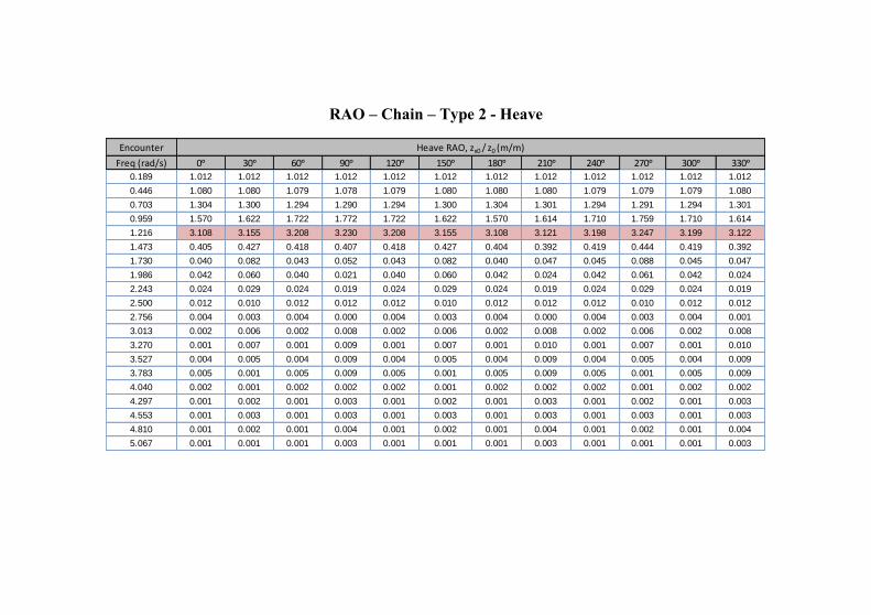
RAO – Chain – Type 2 - Heave
Encounter
Freq (rad/s) 0ᵒ 30ᵒ 60ᵒ 90ᵒ 120ᵒ 150ᵒ 180ᵒ 210ᵒ 240ᵒ 270ᵒ 300ᵒ 330ᵒ
0.189 1.012 1.012 1.012 1.012 1.012 1.012 1.012 1.012 1.012 1.012 1.012 1.012
0.446 1.080 1.080 1.079 1.078 1.079 1.080 1.080 1.080 1.079 1.079 1.079 1.080
0.703 1.304 1.300 1.294 1.290 1.294 1.300 1.304 1.301 1.294 1.291 1.294 1.301
0.959 1.570 1.622 1.722 1.772 1.722 1.622 1.570 1.614 1.710 1.759 1.710 1.614
1.216 3.108 3.155 3.208 3.230 3.208 3.155 3.108 3.121 3.198 3.247 3.199 3.122
1.473 0.405 0.427 0.418 0.407 0.418 0.427 0.404 0.392 0.419 0.444 0.419 0.392
1.730 0.040 0.082 0.043 0.052 0.043 0.082 0.040 0.047 0.045 0.088 0.045 0.047
1.986 0.042 0.060 0.040 0.021 0.040 0.060 0.042 0.024 0.042 0.061 0.042 0.024
2.243 0.024 0.029 0.024 0.019 0.024 0.029 0.024 0.019 0.024 0.029 0.024 0.019
2.500 0.012 0.010 0.012 0.012 0.012 0.010 0.012 0.012 0.012 0.010 0.012 0.012
2.756 0.004 0.003 0.004 0.000 0.004 0.003 0.004 0.000 0.004 0.003 0.004 0.001
3.013 0.002 0.006 0.002 0.008 0.002 0.006 0.002 0.008 0.002 0.006 0.002 0.008
3.270 0.001 0.007 0.001 0.009 0.001 0.007 0.001 0.010 0.001 0.007 0.001 0.010
3.527 0.004 0.005 0.004 0.009 0.004 0.005 0.004 0.009 0.004 0.005 0.004 0.009
3.783 0.005 0.001 0.005 0.009 0.005 0.001 0.005 0.009 0.005 0.001 0.005 0.009
4.040 0.002 0.001 0.002 0.002 0.002 0.001 0.002 0.002 0.002 0.001 0.002 0.002
4.297 0.001 0.002 0.001 0.003 0.001 0.002 0.001 0.003 0.001 0.002 0.001 0.003
4.553 0.001 0.003 0.001 0.003 0.001 0.003 0.001 0.003 0.001 0.003 0.001 0.003
4.810 0.001 0.002 0.001 0.004 0.001 0.002 0.001 0.004 0.001 0.002 0.001 0.004
5.067 0.001 0.001 0.001 0.003 0.001 0.001 0.001 0.003 0.001 0.001 0.001 0.003
Heave RAO, zx0 / z0 (m/m)
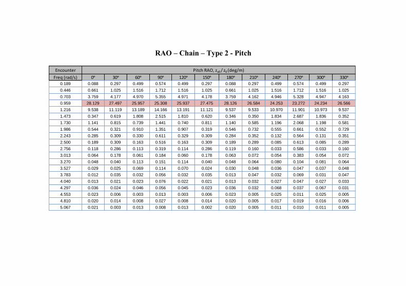
RAO – Chain – Type 2 - Pitch
Encounter
Freq (rad/s) 0ᵒ 30ᵒ 60ᵒ 90ᵒ 120ᵒ 150ᵒ 180ᵒ 210ᵒ 240ᵒ 270ᵒ 300ᵒ 330ᵒ
0.189 0.088 0.297 0.499 0.574 0.499 0.297 0.088 0.297 0.499 0.574 0.499 0.297
0.446 0.661 1.025 1.516 1.712 1.516 1.025 0.661 1.025 1.516 1.712 1.516 1.025
0.703 3.759 4.177 4.970 5.355 4.971 4.178 3.759 4.162 4.946 5.328 4.947 4.163
0.959 28.129 27.497 25.957 25.308 25.937 27.475 28.126 26.584 24.253 23.272 24.234 26.566
1.216 9.538 11.119 13.189 14.166 13.191 11.121 9.537 9.533 10.970 11.901 10.973 9.537
1.473 0.347 0.619 1.808 2.515 1.810 0.620 0.346 0.350 1.834 2.687 1.836 0.352
1.730 1.141 0.815 0.739 1.441 0.740 0.811 1.140 0.585 1.196 2.068 1.198 0.581
1.986 0.544 0.321 0.910 1.351 0.907 0.319 0.546 0.732 0.555 0.661 0.552 0.729
2.243 0.285 0.309 0.330 0.611 0.329 0.309 0.284 0.352 0.132 0.564 0.131 0.351
2.500 0.189 0.309 0.163 0.516 0.163 0.309 0.189 0.289 0.085 0.613 0.085 0.289
2.756 0.118 0.286 0.113 0.319 0.114 0.286 0.119 0.160 0.033 0.586 0.033 0.160
3.013 0.064 0.178 0.061 0.184 0.060 0.178 0.063 0.072 0.054 0.383 0.054 0.072
3.270 0.048 0.040 0.113 0.151 0.114 0.040 0.048 0.064 0.080 0.104 0.081 0.064
3.527 0.029 0.025 0.069 0.114 0.070 0.024 0.030 0.048 0.036 0.047 0.037 0.048
3.783 0.012 0.035 0.032 0.056 0.032 0.035 0.013 0.047 0.032 0.069 0.031 0.047
4.040 0.013 0.021 0.023 0.076 0.022 0.021 0.013 0.032 0.027 0.047 0.027 0.033
4.297 0.036 0.024 0.046 0.056 0.045 0.023 0.036 0.032 0.068 0.037 0.067 0.031
4.553 0.023 0.006 0.003 0.013 0.003 0.006 0.023 0.005 0.025 0.011 0.025 0.005
4.810 0.020 0.014 0.008 0.027 0.008 0.014 0.020 0.005 0.017 0.019 0.016 0.006
5.067 0.021 0.003 0.013 0.008 0.013 0.002 0.020 0.005 0.011 0.010 0.011 0.005
Pitch RAO, zx0 / z0 (deg/m)

RAO – Chain – Type 2 - Roll
Encounter
Freq (rad/s) 0ᵒ 30ᵒ 60ᵒ 90ᵒ 120ᵒ 150ᵒ 180ᵒ 210ᵒ 240ᵒ 270ᵒ 300ᵒ 330ᵒ
0.189 0.858 0.745 0.432 0.000 0.432 0.745 0.858 0.745 0.432 0.000 0.432 0.745
0.446 1.809 1.577 0.922 0.000 0.922 1.577 1.809 1.577 0.922 0.000 0.922 1.577
0.703 4.858 4.278 2.550 0.002 2.552 4.279 4.858 4.280 2.552 0.002 2.554 4.281
0.959 18.927 17.320 10.995 0.025 10.950 17.289 18.926 17.371 11.039 0.023 10.998 17.343
1.216 2.532 2.705 1.999 0.011 2.003 2.705 2.522 2.695 1.989 0.010 2.008 2.712
1.473 0.756 1.492 1.278 0.003 1.284 1.496 0.756 1.343 1.174 0.004 1.180 1.347
1.730 0.730 1.651 1.323 0.002 1.328 1.655 0.732 1.164 0.993 0.004 0.995 1.164
1.986 0.946 0.541 0.111 0.002 0.114 0.540 0.948 1.192 0.716 0.001 0.715 1.190
2.243 0.324 0.497 0.217 0.001 0.219 0.497 0.325 0.553 0.273 0.000 0.272 0.552
2.500 0.086 0.529 0.174 0.001 0.175 0.528 0.087 0.463 0.211 0.000 0.211 0.463
2.756 0.021 0.500 0.065 0.000 0.065 0.500 0.022 0.276 0.170 0.000 0.170 0.276
3.013 0.082 0.321 0.039 0.000 0.041 0.321 0.082 0.145 0.059 0.001 0.060 0.145
3.270 0.116 0.082 0.037 0.001 0.038 0.081 0.116 0.121 0.081 0.000 0.081 0.121
3.527 0.060 0.040 0.009 0.001 0.008 0.041 0.060 0.092 0.055 0.000 0.055 0.092
3.783 0.030 0.060 0.024 0.000 0.024 0.060 0.031 0.059 0.020 0.000 0.020 0.059
4.040 0.029 0.039 0.022 0.001 0.022 0.039 0.030 0.064 0.008 0.000 0.008 0.063
4.297 0.070 0.036 0.051 0.001 0.051 0.035 0.070 0.044 0.020 0.001 0.020 0.043
4.553 0.013 0.008 0.029 0.000 0.029 0.008 0.013 0.010 0.013 0.000 0.013 0.009
4.810 0.008 0.018 0.022 0.000 0.023 0.018 0.008 0.019 0.013 0.000 0.013 0.018
5.067 0.008 0.007 0.017 0.000 0.017 0.007 0.008 0.005 0.019 0.000 0.019 0.005
Rolling RAO, zx0 / z0 (deg/m)
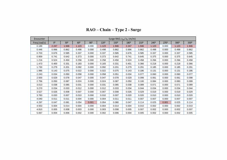
RAO – Chain – Type 2 - Surge
Encounter
Freq (rad/s) 0ᵒ 30ᵒ 60ᵒ 90ᵒ 120ᵒ 150ᵒ 180ᵒ 210ᵒ 240ᵒ 270ᵒ 300ᵒ 330ᵒ
0.189 2.247 1.946 1.123 0.000 1.123 1.946 2.247 1.946 1.123 0.000 1.123 1.946
0.446 0.996 0.862 0.498 0.000 0.498 0.862 0.996 0.862 0.498 0.000 0.498 0.862
0.703 0.676 0.585 0.337 0.000 0.337 0.585 0.676 0.585 0.337 0.000 0.337 0.585
0.959 0.741 0.642 0.373 0.000 0.373 0.642 0.741 0.645 0.375 0.000 0.375 0.645
1.216 0.524 0.450 0.258 0.000 0.258 0.450 0.524 0.458 0.266 0.000 0.266 0.458
1.473 0.400 0.331 0.183 0.000 0.183 0.331 0.401 0.366 0.218 0.000 0.218 0.366
1.730 0.279 0.201 0.092 0.000 0.092 0.201 0.279 0.291 0.185 0.000 0.185 0.291
1.986 0.143 0.075 0.022 0.000 0.022 0.075 0.143 0.186 0.131 0.000 0.131 0.186
2.243 0.034 0.050 0.058 0.000 0.058 0.051 0.034 0.077 0.060 0.000 0.060 0.077
2.500 0.029 0.078 0.047 0.000 0.047 0.078 0.029 0.099 0.061 0.000 0.061 0.098
2.756 0.050 0.087 0.024 0.000 0.024 0.087 0.050 0.100 0.084 0.000 0.083 0.099
3.013 0.038 0.085 0.031 0.000 0.031 0.085 0.038 0.089 0.071 0.000 0.071 0.089
3.270 0.034 0.033 0.012 0.000 0.012 0.033 0.034 0.044 0.034 0.000 0.034 0.044
3.527 0.026 0.008 0.007 0.000 0.007 0.008 0.026 0.029 0.019 0.000 0.019 0.029
3.783 0.020 0.007 0.010 0.000 0.010 0.007 0.020 0.020 0.010 0.000 0.010 0.020
4.040 0.011 0.011 0.004 0.000 0.004 0.011 0.011 0.007 0.007 0.000 0.007 0.007
4.297 0.047 0.081 0.054 0.001 0.054 0.080 0.047 0.114 0.025 0.001 0.025 0.114
4.553 0.004 0.014 0.004 0.000 0.004 0.014 0.004 0.010 0.002 0.000 0.002 0.010
4.810 0.005 0.008 0.003 0.000 0.003 0.008 0.005 0.007 0.002 0.000 0.002 0.007
5.067 0.004 0.006 0.002 0.000 0.002 0.006 0.004 0.005 0.002 0.000 0.002 0.005
Surge RAO, zx0 / z0 (m/m)
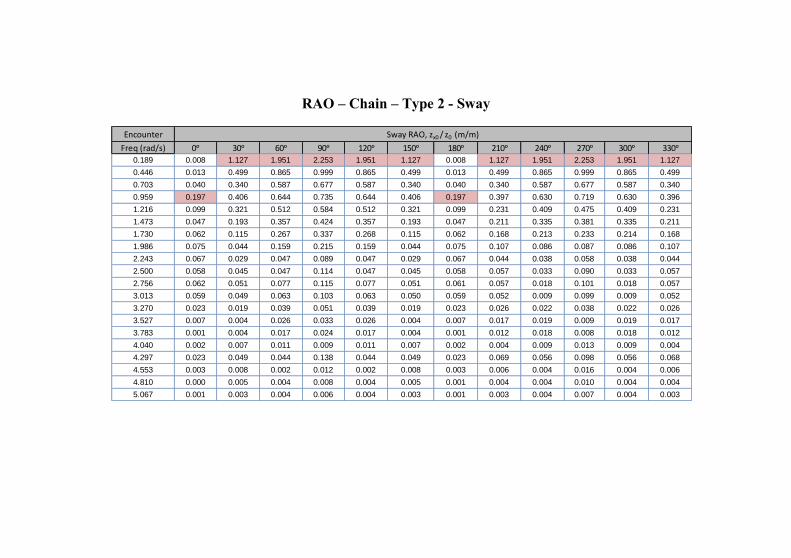
RAO – Chain – Type 2 - Sway
Encounter
Freq (rad/s) 0ᵒ 30ᵒ 60ᵒ 90ᵒ 120ᵒ 150ᵒ 180ᵒ 210ᵒ 240ᵒ 270ᵒ 300ᵒ 330ᵒ
0.189 0.008 1.127 1.951 2.253 1.951 1.127 0.008 1.127 1.951 2.253 1.951 1.127
0.446 0.013 0.499 0.865 0.999 0.865 0.499 0.013 0.499 0.865 0.999 0.865 0.499
0.703 0.040 0.340 0.587 0.677 0.587 0.340 0.040 0.340 0.587 0.677 0.587 0.340
0.959 0.197 0.406 0.644 0.735 0.644 0.406 0.197 0.397 0.630 0.719 0.630 0.396
1.216 0.099 0.321 0.512 0.584 0.512 0.321 0.099 0.231 0.409 0.475 0.409 0.231
1.473 0.047 0.193 0.357 0.424 0.357 0.193 0.047 0.211 0.335 0.381 0.335 0.211
1.730 0.062 0.115 0.267 0.337 0.268 0.115 0.062 0.168 0.213 0.233 0.214 0.168
1.986 0.075 0.044 0.159 0.215 0.159 0.044 0.075 0.107 0.086 0.087 0.086 0.107
2.243 0.067 0.029 0.047 0.089 0.047 0.029 0.067 0.044 0.038 0.058 0.038 0.044
2.500 0.058 0.045 0.047 0.114 0.047 0.045 0.058 0.057 0.033 0.090 0.033 0.057
2.756 0.062 0.051 0.077 0.115 0.077 0.051 0.061 0.057 0.018 0.101 0.018 0.057
3.013 0.059 0.049 0.063 0.103 0.063 0.050 0.059 0.052 0.009 0.099 0.009 0.052
3.270 0.023 0.019 0.039 0.051 0.039 0.019 0.023 0.026 0.022 0.038 0.022 0.026
3.527 0.007 0.004 0.026 0.033 0.026 0.004 0.007 0.017 0.019 0.009 0.019 0.017
3.783 0.001 0.004 0.017 0.024 0.017 0.004 0.001 0.012 0.018 0.008 0.018 0.012
4.040 0.002 0.007 0.011 0.009 0.011 0.007 0.002 0.004 0.009 0.013 0.009 0.004
4.297 0.023 0.049 0.044 0.138 0.044 0.049 0.023 0.069 0.056 0.098 0.056 0.068
4.553 0.003 0.008 0.002 0.012 0.002 0.008 0.003 0.006 0.004 0.016 0.004 0.006
4.810 0.000 0.005 0.004 0.008 0.004 0.005 0.001 0.004 0.004 0.010 0.004 0.004
5.067 0.001 0.003 0.004 0.006 0.004 0.003 0.001 0.003 0.004 0.007 0.004 0.003
Sway RAO, zx0 / z0 (m/m)
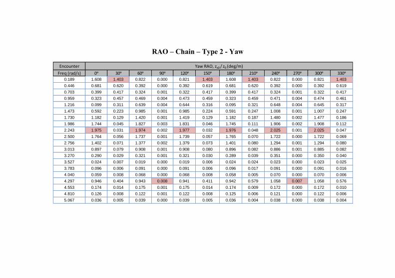
RAO – Chain – Type 2 - Yaw
Encounter
Freq (rad/s) 0ᵒ 30ᵒ 60ᵒ 90ᵒ 120ᵒ 150ᵒ 180ᵒ 210ᵒ 240ᵒ 270ᵒ 300ᵒ 330ᵒ
0.189 1.608 1.403 0.822 0.000 0.821 1.403 1.608 1.403 0.822 0.000 0.821 1.403
0.446 0.681 0.620 0.392 0.000 0.392 0.619 0.681 0.620 0.392 0.000 0.392 0.619
0.703 0.399 0.417 0.324 0.001 0.322 0.417 0.399 0.417 0.324 0.001 0.322 0.417
0.959 0.323 0.457 0.469 0.004 0.473 0.459 0.323 0.459 0.471 0.004 0.474 0.461
1.216 0.099 0.311 0.639 0.004 0.644 0.316 0.095 0.321 0.648 0.004 0.645 0.317
1.473 0.592 0.223 0.985 0.001 0.985 0.224 0.591 0.247 1.008 0.001 1.007 0.247
1.730 1.182 0.129 1.420 0.001 1.419 0.129 1.182 0.187 1.480 0.002 1.477 0.186
1.986 1.744 0.045 1.827 0.003 1.831 0.046 1.745 0.111 1.906 0.002 1.908 0.112
2.243 1.975 0.031 1.974 0.002 1.977 0.032 1.976 0.048 2.025 0.001 2.025 0.047
2.500 1.764 0.056 1.737 0.001 1.739 0.057 1.765 0.070 1.722 0.000 1.722 0.069
2.756 1.402 0.071 1.377 0.002 1.379 0.073 1.401 0.080 1.294 0.001 1.294 0.080
3.013 0.897 0.079 0.908 0.001 0.908 0.080 0.896 0.082 0.886 0.001 0.885 0.082
3.270 0.290 0.029 0.321 0.001 0.321 0.030 0.289 0.039 0.351 0.000 0.350 0.040
3.527 0.024 0.007 0.019 0.000 0.019 0.006 0.024 0.024 0.023 0.000 0.023 0.025
3.783 0.096 0.006 0.091 0.000 0.091 0.006 0.096 0.017 0.091 0.000 0.091 0.016
4.040 0.059 0.008 0.068 0.000 0.068 0.008 0.058 0.005 0.070 0.000 0.070 0.006
4.297 0.946 0.404 0.943 0.008 0.941 0.411 0.942 0.579 1.058 0.007 1.058 0.576
4.553 0.174 0.014 0.175 0.001 0.175 0.014 0.174 0.009 0.172 0.000 0.172 0.010
4.810 0.126 0.008 0.122 0.001 0.122 0.008 0.125 0.006 0.121 0.000 0.122 0.006
5.067 0.036 0.005 0.039 0.000 0.039 0.005 0.036 0.004 0.038 0.000 0.038 0.004
Yaw RAO, zx0 / z0 (deg/m)
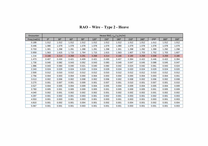
RAO – Wire – Type 2 - Heave
Encounter
Freq (rad/s) 0ᵒ 30ᵒ 60ᵒ 90ᵒ 120ᵒ 150ᵒ 180ᵒ 210ᵒ 240ᵒ 270ᵒ 300ᵒ 330ᵒ
0.189 1.012 1.012 1.012 1.012 1.012 1.012 1.012 1.012 1.012 1.012 1.012 1.012
0.446 1.080 1.079 1.078 1.078 1.078 1.079 1.080 1.079 1.078 1.078 1.078 1.079
0.703 1.301 1.298 1.291 1.288 1.291 1.298 1.301 1.298 1.292 1.289 1.292 1.298
0.959 1.563 1.615 1.715 1.764 1.715 1.615 1.563 1.607 1.703 1.752 1.703 1.607
1.216 3.166 3.214 3.268 3.291 3.268 3.214 3.166 3.180 3.258 3.308 3.259 3.180
1.473 0.407 0.430 0.421 0.409 0.421 0.430 0.407 0.394 0.422 0.446 0.422 0.394
1.730 0.040 0.082 0.043 0.052 0.043 0.083 0.040 0.047 0.045 0.088 0.045 0.047
1.986 0.043 0.060 0.040 0.021 0.040 0.060 0.042 0.024 0.042 0.061 0.043 0.024
2.243 0.024 0.029 0.024 0.019 0.024 0.029 0.024 0.020 0.024 0.029 0.024 0.020
2.500 0.012 0.010 0.012 0.012 0.012 0.010 0.012 0.012 0.012 0.010 0.012 0.012
2.756 0.004 0.003 0.004 0.000 0.004 0.003 0.004 0.000 0.004 0.003 0.004 0.001
3.013 0.002 0.006 0.002 0.008 0.002 0.006 0.002 0.008 0.002 0.006 0.002 0.008
3.270 0.001 0.007 0.001 0.009 0.001 0.007 0.001 0.010 0.001 0.007 0.001 0.010
3.527 0.004 0.005 0.004 0.009 0.004 0.005 0.004 0.009 0.004 0.005 0.004 0.009
3.783 0.005 0.001 0.005 0.009 0.005 0.001 0.005 0.009 0.005 0.001 0.005 0.009
4.040 0.002 0.001 0.002 0.002 0.002 0.001 0.002 0.002 0.002 0.001 0.002 0.002
4.297 0.001 0.002 0.001 0.003 0.001 0.002 0.001 0.003 0.001 0.002 0.001 0.003
4.553 0.001 0.003 0.001 0.003 0.001 0.003 0.001 0.003 0.001 0.003 0.001 0.003
4.810 0.001 0.002 0.001 0.004 0.001 0.002 0.001 0.004 0.001 0.002 0.001 0.004
5.067 0.001 0.001 0.001 0.003 0.001 0.001 0.001 0.003 0.001 0.001 0.001 0.003
Heave RAO, zx0 / z0 (m/m)

RAO – Wire – Type 2 - Pitch
Encounter
Freq (rad/s) 0ᵒ 30ᵒ 60ᵒ 90ᵒ 120ᵒ 150ᵒ 180ᵒ 210ᵒ 240ᵒ 270ᵒ 300ᵒ 330ᵒ
0.189 0.088 0.297 0.500 0.575 0.499 0.297 0.088 0.297 0.500 0.575 0.499 0.297
0.446 0.659 1.024 1.516 1.713 1.516 1.024 0.659 1.024 1.516 1.713 1.516 1.024
0.703 3.744 4.166 4.965 5.353 4.966 4.167 3.745 4.152 4.942 5.327 4.943 4.152
0.959 27.976 27.348 25.827 25.192 25.807 27.326 27.973 26.444 24.140 23.178 24.121 26.425
1.216 9.718 11.308 13.379 14.356 13.381 11.309 9.717 9.698 11.121 12.048 11.124 9.701
1.473 0.344 0.623 1.813 2.520 1.815 0.624 0.344 0.354 1.838 2.691 1.840 0.355
1.730 1.140 0.815 0.740 1.442 0.741 0.811 1.140 0.585 1.198 2.068 1.199 0.581
1.986 0.544 0.321 0.909 1.349 0.906 0.319 0.546 0.731 0.555 0.661 0.552 0.728
2.243 0.284 0.309 0.330 0.610 0.329 0.309 0.284 0.351 0.132 0.563 0.130 0.350
2.500 0.188 0.309 0.163 0.516 0.163 0.309 0.188 0.289 0.084 0.612 0.084 0.289
2.756 0.118 0.285 0.113 0.318 0.113 0.285 0.118 0.160 0.033 0.586 0.033 0.160
3.013 0.063 0.177 0.060 0.183 0.060 0.178 0.062 0.072 0.054 0.383 0.054 0.072
3.270 0.048 0.040 0.113 0.150 0.114 0.040 0.048 0.064 0.080 0.104 0.081 0.064
3.527 0.029 0.025 0.069 0.114 0.070 0.024 0.030 0.048 0.036 0.047 0.037 0.048
3.783 0.012 0.035 0.032 0.056 0.032 0.035 0.013 0.047 0.032 0.069 0.031 0.047
4.040 0.013 0.021 0.023 0.076 0.022 0.021 0.013 0.032 0.027 0.047 0.027 0.033
4.297 0.036 0.023 0.046 0.056 0.045 0.023 0.036 0.032 0.068 0.037 0.067 0.031
4.553 0.023 0.006 0.003 0.014 0.003 0.006 0.023 0.005 0.025 0.011 0.025 0.005
4.810 0.020 0.013 0.008 0.027 0.008 0.014 0.020 0.005 0.017 0.019 0.016 0.006
5.067 0.021 0.003 0.013 0.008 0.013 0.002 0.020 0.005 0.011 0.010 0.011 0.005
Pitch RAO, zx0 / z0 (deg/m)
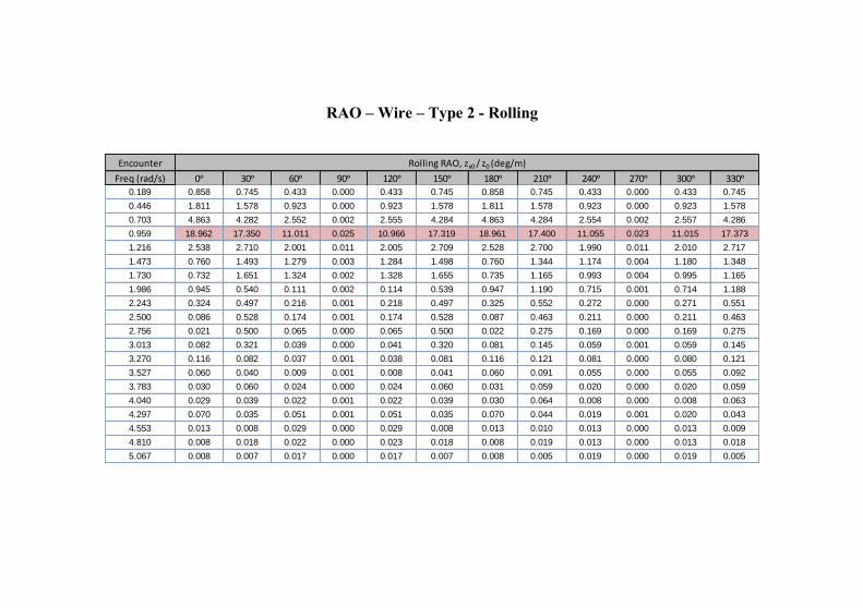
RAO – Wire – Type 2 - Rolling
Encounter
Freq (rad/s) 0ᵒ 30ᵒ 60ᵒ 90ᵒ 120ᵒ 150ᵒ 180ᵒ 210ᵒ 240ᵒ 270ᵒ 300ᵒ 330ᵒ
0.189 0.858 0.745 0.433 0.000 0.433 0.745 0.858 0.745 0.433 0.000 0.433 0.745
0.446 1.811 1.578 0.923 0.000 0.923 1.578 1.811 1.578 0.923 0.000 0.923 1.578
0.703 4.863 4.282 2.552 0.002 2.555 4.284 4.863 4.284 2.554 0.002 2.557 4.286
0.959 18.962 17.350 11.011 0.025 10.966 17.319 18.961 17.400 11.055 0.023 11.015 17.373
1.216 2.538 2.710 2.001 0.011 2.005 2.709 2.528 2.700 1.990 0.011 2.010 2.717
1.473 0.760 1.493 1.279 0.003 1.284 1.498 0.760 1.344 1.174 0.004 1.180 1.348
1.730 0.732 1.651 1.324 0.002 1.328 1.655 0.735 1.165 0.993 0.004 0.995 1.165
1.986 0.945 0.540 0.111 0.002 0.114 0.539 0.947 1.190 0.715 0.001 0.714 1.188
2.243 0.324 0.497 0.216 0.001 0.218 0.497 0.325 0.552 0.272 0.000 0.271 0.551
2.500 0.086 0.528 0.174 0.001 0.174 0.528 0.087 0.463 0.211 0.000 0.211 0.463
2.756 0.021 0.500 0.065 0.000 0.065 0.500 0.022 0.275 0.169 0.000 0.169 0.275
3.013 0.082 0.321 0.039 0.000 0.041 0.320 0.081 0.145 0.059 0.001 0.059 0.145
3.270 0.116 0.082 0.037 0.001 0.038 0.081 0.116 0.121 0.081 0.000 0.080 0.121
3.527 0.060 0.040 0.009 0.001 0.008 0.041 0.060 0.091 0.055 0.000 0.055 0.092
3.783 0.030 0.060 0.024 0.000 0.024 0.060 0.031 0.059 0.020 0.000 0.020 0.059
4.040 0.029 0.039 0.022 0.001 0.022 0.039 0.030 0.064 0.008 0.000 0.008 0.063
4.297 0.070 0.035 0.051 0.001 0.051 0.035 0.070 0.044 0.019 0.001 0.020 0.043
4.553 0.013 0.008 0.029 0.000 0.029 0.008 0.013 0.010 0.013 0.000 0.013 0.009
4.810 0.008 0.018 0.022 0.000 0.023 0.018 0.008 0.019 0.013 0.000 0.013 0.018
5.067 0.008 0.007 0.017 0.000 0.017 0.007 0.008 0.005 0.019 0.000 0.019 0.005
Rolling RAO, zx0 / z0 (deg/m)
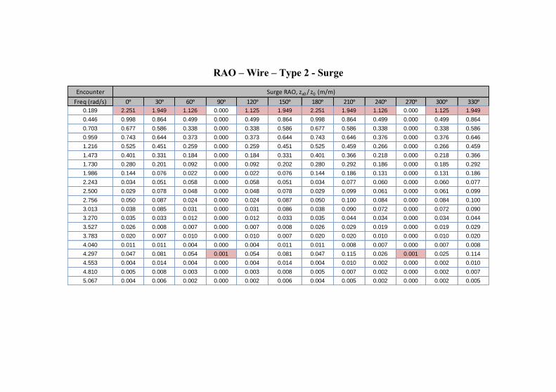
RAO – Wire – Type 2 - Surge
Encounter
Freq (rad/s) 0ᵒ 30ᵒ 60ᵒ 90ᵒ 120ᵒ 150ᵒ 180ᵒ 210ᵒ 240ᵒ 270ᵒ 300ᵒ 330ᵒ
0.189 2.251 1.949 1.126 0.000 1.125 1.949 2.251 1.949 1.126 0.000 1.125 1.949
0.446 0.998 0.864 0.499 0.000 0.499 0.864 0.998 0.864 0.499 0.000 0.499 0.864
0.703 0.677 0.586 0.338 0.000 0.338 0.586 0.677 0.586 0.338 0.000 0.338 0.586
0.959 0.743 0.644 0.373 0.000 0.373 0.644 0.743 0.646 0.376 0.000 0.376 0.646
1.216 0.525 0.451 0.259 0.000 0.259 0.451 0.525 0.459 0.266 0.000 0.266 0.459
1.473 0.401 0.331 0.184 0.000 0.184 0.331 0.401 0.366 0.218 0.000 0.218 0.366
1.730 0.280 0.201 0.092 0.000 0.092 0.202 0.280 0.292 0.186 0.000 0.185 0.292
1.986 0.144 0.076 0.022 0.000 0.022 0.076 0.144 0.186 0.131 0.000 0.131 0.186
2.243 0.034 0.051 0.058 0.000 0.058 0.051 0.034 0.077 0.060 0.000 0.060 0.077
2.500 0.029 0.078 0.048 0.000 0.048 0.078 0.029 0.099 0.061 0.000 0.061 0.099
2.756 0.050 0.087 0.024 0.000 0.024 0.087 0.050 0.100 0.084 0.000 0.084 0.100
3.013 0.038 0.085 0.031 0.000 0.031 0.086 0.038 0.090 0.072 0.000 0.072 0.090
3.270 0.035 0.033 0.012 0.000 0.012 0.033 0.035 0.044 0.034 0.000 0.034 0.044
3.527 0.026 0.008 0.007 0.000 0.007 0.008 0.026 0.029 0.019 0.000 0.019 0.029
3.783 0.020 0.007 0.010 0.000 0.010 0.007 0.020 0.020 0.010 0.000 0.010 0.020
4.040 0.011 0.011 0.004 0.000 0.004 0.011 0.011 0.008 0.007 0.000 0.007 0.008
4.297 0.047 0.081 0.054 0.001 0.054 0.081 0.047 0.115 0.026 0.001 0.025 0.114
4.553 0.004 0.014 0.004 0.000 0.004 0.014 0.004 0.010 0.002 0.000 0.002 0.010
4.810 0.005 0.008 0.003 0.000 0.003 0.008 0.005 0.007 0.002 0.000 0.002 0.007
5.067 0.004 0.006 0.002 0.000 0.002 0.006 0.004 0.005 0.002 0.000 0.002 0.005
Surge RAO, zx0 / z0 (m/m)
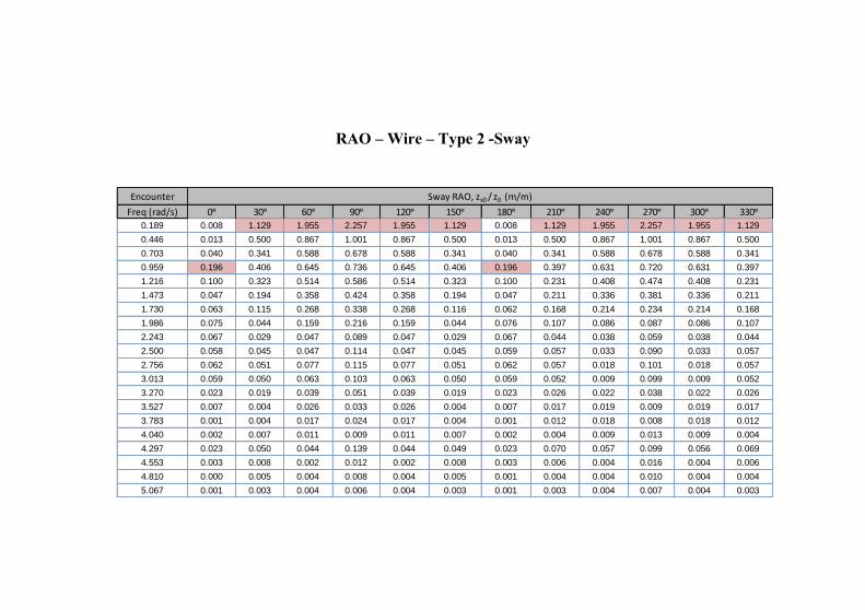
RAO – Wire – Type 2 -Sway
Encounter
Freq (rad/s) 0ᵒ 30ᵒ 60ᵒ 90ᵒ 120ᵒ 150ᵒ 180ᵒ 210ᵒ 240ᵒ 270ᵒ 300ᵒ 330ᵒ
0.189 0.008 1.129 1.955 2.257 1.955 1.129 0.008 1.129 1.955 2.257 1.955 1.129
0.446 0.013 0.500 0.867 1.001 0.867 0.500 0.013 0.500 0.867 1.001 0.867 0.500
0.703 0.040 0.341 0.588 0.678 0.588 0.341 0.040 0.341 0.588 0.678 0.588 0.341
0.959 0.196 0.406 0.645 0.736 0.645 0.406 0.196 0.397 0.631 0.720 0.631 0.397
1.216 0.100 0.323 0.514 0.586 0.514 0.323 0.100 0.231 0.408 0.474 0.408 0.231
1.473 0.047 0.194 0.358 0.424 0.358 0.194 0.047 0.211 0.336 0.381 0.336 0.211
1.730 0.063 0.115 0.268 0.338 0.268 0.116 0.062 0.168 0.214 0.234 0.214 0.168
1.986 0.075 0.044 0.159 0.216 0.159 0.044 0.076 0.107 0.086 0.087 0.086 0.107
2.243 0.067 0.029 0.047 0.089 0.047 0.029 0.067 0.044 0.038 0.059 0.038 0.044
2.500 0.058 0.045 0.047 0.114 0.047 0.045 0.059 0.057 0.033 0.090 0.033 0.057
2.756 0.062 0.051 0.077 0.115 0.077 0.051 0.062 0.057 0.018 0.101 0.018 0.057
3.013 0.059 0.050 0.063 0.103 0.063 0.050 0.059 0.052 0.009 0.099 0.009 0.052
3.270 0.023 0.019 0.039 0.051 0.039 0.019 0.023 0.026 0.022 0.038 0.022 0.026
3.527 0.007 0.004 0.026 0.033 0.026 0.004 0.007 0.017 0.019 0.009 0.019 0.017
3.783 0.001 0.004 0.017 0.024 0.017 0.004 0.001 0.012 0.018 0.008 0.018 0.012
4.040 0.002 0.007 0.011 0.009 0.011 0.007 0.002 0.004 0.009 0.013 0.009 0.004
4.297 0.023 0.050 0.044 0.139 0.044 0.049 0.023 0.070 0.057 0.099 0.056 0.069
4.553 0.003 0.008 0.002 0.012 0.002 0.008 0.003 0.006 0.004 0.016 0.004 0.006
4.810 0.000 0.005 0.004 0.008 0.004 0.005 0.001 0.004 0.004 0.010 0.004 0.004
5.067 0.001 0.003 0.004 0.006 0.004 0.003 0.001 0.003 0.004 0.007 0.004 0.003
Sway RAO, zx0 / z0 (m/m)
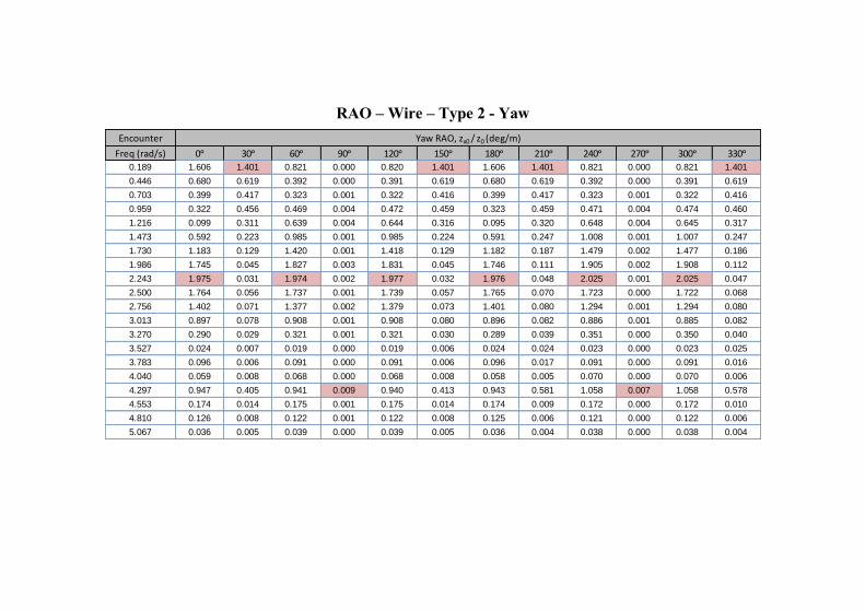
RAO – Wire – Type 2 - Yaw
Encounter
Freq (rad/s) 0ᵒ 30ᵒ 60ᵒ 90ᵒ 120ᵒ 150ᵒ 180ᵒ 210ᵒ 240ᵒ 270ᵒ 300ᵒ 330ᵒ
0.189 1.606 1.401 0.821 0.000 0.820 1.401 1.606 1.401 0.821 0.000 0.821 1.401
0.446 0.680 0.619 0.392 0.000 0.391 0.619 0.680 0.619 0.392 0.000 0.391 0.619
0.703 0.399 0.417 0.323 0.001 0.322 0.416 0.399 0.417 0.323 0.001 0.322 0.416
0.959 0.322 0.456 0.469 0.004 0.472 0.459 0.323 0.459 0.471 0.004 0.474 0.460
1.216 0.099 0.311 0.639 0.004 0.644 0.316 0.095 0.320 0.648 0.004 0.645 0.317
1.473 0.592 0.223 0.985 0.001 0.985 0.224 0.591 0.247 1.008 0.001 1.007 0.247
1.730 1.183 0.129 1.420 0.001 1.418 0.129 1.182 0.187 1.479 0.002 1.477 0.186
1.986 1.745 0.045 1.827 0.003 1.831 0.045 1.746 0.111 1.905 0.002 1.908 0.112
2.243 1.975 0.031 1.974 0.002 1.977 0.032 1.976 0.048 2.025 0.001 2.025 0.047
2.500 1.764 0.056 1.737 0.001 1.739 0.057 1.765 0.070 1.723 0.000 1.722 0.068
2.756 1.402 0.071 1.377 0.002 1.379 0.073 1.401 0.080 1.294 0.001 1.294 0.080
3.013 0.897 0.078 0.908 0.001 0.908 0.080 0.896 0.082 0.886 0.001 0.885 0.082
3.270 0.290 0.029 0.321 0.001 0.321 0.030 0.289 0.039 0.351 0.000 0.350 0.040
3.527 0.024 0.007 0.019 0.000 0.019 0.006 0.024 0.024 0.023 0.000 0.023 0.025
3.783 0.096 0.006 0.091 0.000 0.091 0.006 0.096 0.017 0.091 0.000 0.091 0.016
4.040 0.059 0.008 0.068 0.000 0.068 0.008 0.058 0.005 0.070 0.000 0.070 0.006
4.297 0.947 0.405 0.941 0.009 0.940 0.413 0.943 0.581 1.058 0.007 1.058 0.578
4.553 0.174 0.014 0.175 0.001 0.175 0.014 0.174 0.009 0.172 0.000 0.172 0.010
4.810 0.126 0.008 0.122 0.001 0.122 0.008 0.125 0.006 0.121 0.000 0.122 0.006
5.067 0.036 0.005 0.039 0.000 0.039 0.005 0.036 0.004 0.038 0.000 0.038 0.004
Yaw RAO, zx0 / z0 (deg/m)
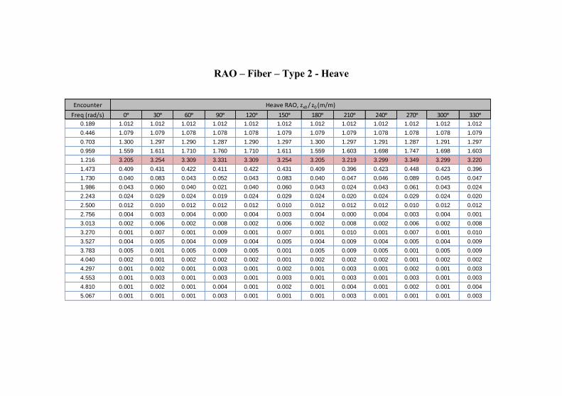
RAO – Fiber – Type 2 - Heave
Encounter
Freq (rad/s) 0ᵒ 30ᵒ 60ᵒ 90ᵒ 120ᵒ 150ᵒ 180ᵒ 210ᵒ 240ᵒ 270ᵒ 300ᵒ 330ᵒ
0.189 1.012 1.012 1.012 1.012 1.012 1.012 1.012 1.012 1.012 1.012 1.012 1.012
0.446 1.079 1.079 1.078 1.078 1.078 1.079 1.079 1.079 1.078 1.078 1.078 1.079
0.703 1.300 1.297 1.290 1.287 1.290 1.297 1.300 1.297 1.291 1.287 1.291 1.297
0.959 1.559 1.611 1.710 1.760 1.710 1.611 1.559 1.603 1.698 1.747 1.698 1.603
1.216 3.205 3.254 3.309 3.331 3.309 3.254 3.205 3.219 3.299 3.349 3.299 3.220
1.473 0.409 0.431 0.422 0.411 0.422 0.431 0.409 0.396 0.423 0.448 0.423 0.396
1.730 0.040 0.083 0.043 0.052 0.043 0.083 0.040 0.047 0.046 0.089 0.045 0.047
1.986 0.043 0.060 0.040 0.021 0.040 0.060 0.043 0.024 0.043 0.061 0.043 0.024
2.243 0.024 0.029 0.024 0.019 0.024 0.029 0.024 0.020 0.024 0.029 0.024 0.020
2.500 0.012 0.010 0.012 0.012 0.012 0.010 0.012 0.012 0.012 0.010 0.012 0.012
2.756 0.004 0.003 0.004 0.000 0.004 0.003 0.004 0.000 0.004 0.003 0.004 0.001
3.013 0.002 0.006 0.002 0.008 0.002 0.006 0.002 0.008 0.002 0.006 0.002 0.008
3.270 0.001 0.007 0.001 0.009 0.001 0.007 0.001 0.010 0.001 0.007 0.001 0.010
3.527 0.004 0.005 0.004 0.009 0.004 0.005 0.004 0.009 0.004 0.005 0.004 0.009
3.783 0.005 0.001 0.005 0.009 0.005 0.001 0.005 0.009 0.005 0.001 0.005 0.009
4.040 0.002 0.001 0.002 0.002 0.002 0.001 0.002 0.002 0.002 0.001 0.002 0.002
4.297 0.001 0.002 0.001 0.003 0.001 0.002 0.001 0.003 0.001 0.002 0.001 0.003
4.553 0.001 0.003 0.001 0.003 0.001 0.003 0.001 0.003 0.001 0.003 0.001 0.003
4.810 0.001 0.002 0.001 0.004 0.001 0.002 0.001 0.004 0.001 0.002 0.001 0.004
5.067 0.001 0.001 0.001 0.003 0.001 0.001 0.001 0.003 0.001 0.001 0.001 0.003
Heave RAO, zx0 / z0 (m/m)
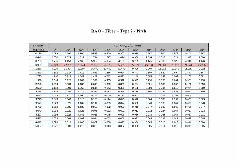
RAO – Fiber – Type 2 - Pitch
Encounter
Freq (rad/s) 0ᵒ 30ᵒ 60ᵒ 90ᵒ 120ᵒ 150ᵒ 180ᵒ 210ᵒ 240ᵒ 270ᵒ 300ᵒ 330ᵒ
0.189 0.088 0.297 0.500 0.575 0.500 0.297 0.088 0.297 0.500 0.575 0.500 0.297
0.446 0.658 1.024 1.517 1.714 1.517 1.024 0.658 1.024 1.517 1.714 1.517 1.024
0.703 3.735 4.159 4.963 5.352 4.964 4.160 3.735 4.145 4.939 5.326 4.940 4.146
0.959 27.876 27.251 25.743 25.116 25.723 27.229 27.873 26.353 24.068 23.117 24.049 26.335
1.216 9.839 11.434 13.507 14.483 13.509 11.436 9.838 9.809 11.222 12.146 11.225 9.812
1.473 0.342 0.626 1.816 2.522 1.818 0.626 0.342 0.356 1.840 2.694 1.843 0.357
1.730 1.140 0.815 0.741 1.442 0.742 0.811 1.140 0.585 1.198 2.069 1.200 0.581
1.986 0.544 0.320 0.908 1.348 0.905 0.319 0.545 0.730 0.555 0.661 0.551 0.728
2.243 0.284 0.309 0.330 0.610 0.329 0.309 0.284 0.351 0.132 0.563 0.130 0.350
2.500 0.188 0.309 0.163 0.515 0.163 0.308 0.188 0.289 0.084 0.612 0.084 0.289
2.756 0.118 0.285 0.113 0.318 0.113 0.285 0.118 0.160 0.033 0.585 0.033 0.160
3.013 0.063 0.177 0.060 0.183 0.060 0.177 0.062 0.072 0.054 0.382 0.054 0.072
3.270 0.048 0.040 0.113 0.150 0.114 0.040 0.048 0.064 0.080 0.104 0.081 0.063
3.527 0.029 0.025 0.069 0.114 0.069 0.024 0.030 0.048 0.036 0.047 0.037 0.048
3.783 0.012 0.035 0.032 0.056 0.032 0.035 0.013 0.047 0.032 0.069 0.031 0.047
4.040 0.013 0.021 0.023 0.076 0.022 0.021 0.013 0.032 0.027 0.047 0.027 0.033
4.297 0.036 0.023 0.046 0.056 0.045 0.023 0.036 0.033 0.068 0.037 0.067 0.031
4.553 0.023 0.006 0.003 0.014 0.003 0.006 0.023 0.005 0.025 0.011 0.025 0.005
4.810 0.020 0.013 0.008 0.027 0.008 0.013 0.020 0.005 0.016 0.019 0.016 0.006
5.067 0.021 0.003 0.013 0.008 0.013 0.002 0.020 0.005 0.011 0.010 0.011 0.005
Pitch RAO, zx0 / z0 (deg/m)
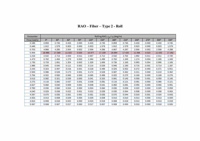
RAO – Fiber – Type 2 - Roll
Encounter
Freq (rad/s) 0ᵒ 30ᵒ 60ᵒ 90ᵒ 120ᵒ 150ᵒ 180ᵒ 210ᵒ 240ᵒ 270ᵒ 300ᵒ 330ᵒ
0.189 0.859 0.745 0.433 0.000 0.433 0.745 0.859 0.745 0.433 0.000 0.433 0.745
0.446 1.812 1.579 0.923 0.000 0.923 1.579 1.812 1.579 0.923 0.000 0.923 1.579
0.703 4.866 4.285 2.554 0.002 2.556 4.286 4.867 4.287 2.556 0.002 2.558 4.288
0.959 18.985 17.369 11.022 0.025 10.977 17.339 18.984 17.420 11.066 0.023 11.025 17.392
1.216 2.542 2.713 2.003 0.011 2.007 2.712 2.532 2.702 1.992 0.011 2.011 2.720
1.473 0.762 1.494 1.279 0.003 1.284 1.499 0.762 1.345 1.174 0.004 1.180 1.349
1.730 0.733 1.651 1.324 0.002 1.329 1.656 0.736 1.165 0.993 0.004 0.995 1.165
1.986 0.945 0.540 0.111 0.002 0.114 0.539 0.946 1.190 0.715 0.001 0.714 1.187
2.243 0.324 0.497 0.216 0.001 0.218 0.496 0.325 0.552 0.272 0.000 0.271 0.551
2.500 0.086 0.528 0.173 0.001 0.174 0.528 0.087 0.462 0.211 0.000 0.210 0.462
2.756 0.022 0.500 0.065 0.000 0.065 0.499 0.022 0.275 0.169 0.000 0.169 0.275
3.013 0.082 0.321 0.039 0.000 0.041 0.320 0.081 0.145 0.059 0.001 0.059 0.145
3.270 0.116 0.082 0.037 0.001 0.038 0.081 0.116 0.121 0.081 0.000 0.080 0.121
3.527 0.060 0.040 0.009 0.001 0.008 0.041 0.060 0.091 0.055 0.000 0.055 0.091
3.783 0.030 0.060 0.024 0.000 0.024 0.060 0.030 0.059 0.020 0.000 0.020 0.059
4.040 0.029 0.039 0.022 0.001 0.022 0.039 0.030 0.064 0.008 0.000 0.008 0.063
4.297 0.070 0.035 0.051 0.001 0.051 0.035 0.070 0.044 0.019 0.001 0.020 0.043
4.553 0.013 0.008 0.029 0.000 0.029 0.008 0.013 0.010 0.013 0.000 0.013 0.009
4.810 0.008 0.018 0.022 0.000 0.023 0.018 0.008 0.019 0.013 0.000 0.013 0.018
5.067 0.008 0.007 0.017 0.000 0.017 0.007 0.008 0.005 0.019 0.000 0.019 0.005
Rolling RAO, zx0 / z0 (deg/m)
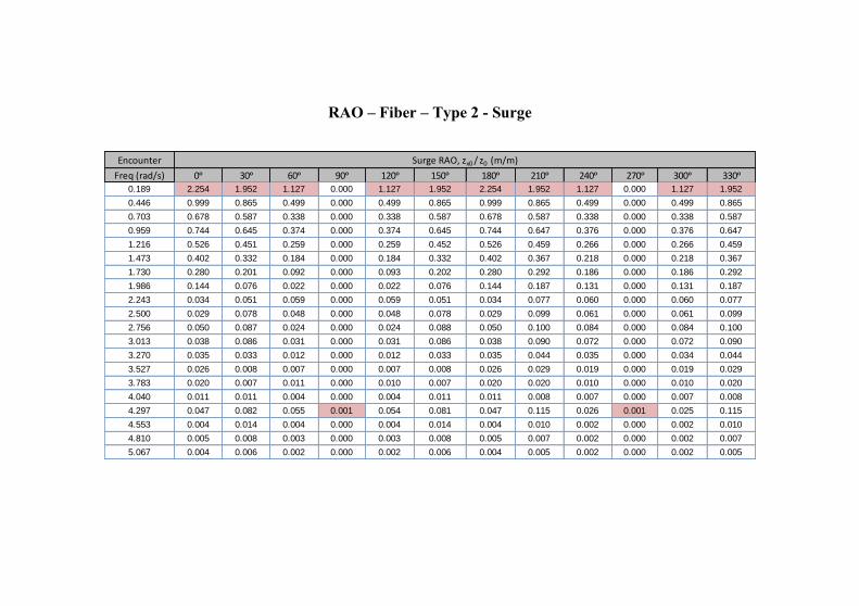
RAO – Fiber – Type 2 - Surge
Encounter
Freq (rad/s) 0ᵒ 30ᵒ 60ᵒ 90ᵒ 120ᵒ 150ᵒ 180ᵒ 210ᵒ 240ᵒ 270ᵒ 300ᵒ 330ᵒ
0.189 2.254 1.952 1.127 0.000 1.127 1.952 2.254 1.952 1.127 0.000 1.127 1.952
0.446 0.999 0.865 0.499 0.000 0.499 0.865 0.999 0.865 0.499 0.000 0.499 0.865
0.703 0.678 0.587 0.338 0.000 0.338 0.587 0.678 0.587 0.338 0.000 0.338 0.587
0.959 0.744 0.645 0.374 0.000 0.374 0.645 0.744 0.647 0.376 0.000 0.376 0.647
1.216 0.526 0.451 0.259 0.000 0.259 0.452 0.526 0.459 0.266 0.000 0.266 0.459
1.473 0.402 0.332 0.184 0.000 0.184 0.332 0.402 0.367 0.218 0.000 0.218 0.367
1.730 0.280 0.201 0.092 0.000 0.093 0.202 0.280 0.292 0.186 0.000 0.186 0.292
1.986 0.144 0.076 0.022 0.000 0.022 0.076 0.144 0.187 0.131 0.000 0.131 0.187
2.243 0.034 0.051 0.059 0.000 0.059 0.051 0.034 0.077 0.060 0.000 0.060 0.077
2.500 0.029 0.078 0.048 0.000 0.048 0.078 0.029 0.099 0.061 0.000 0.061 0.099
2.756 0.050 0.087 0.024 0.000 0.024 0.088 0.050 0.100 0.084 0.000 0.084 0.100
3.013 0.038 0.086 0.031 0.000 0.031 0.086 0.038 0.090 0.072 0.000 0.072 0.090
3.270 0.035 0.033 0.012 0.000 0.012 0.033 0.035 0.044 0.035 0.000 0.034 0.044
3.527 0.026 0.008 0.007 0.000 0.007 0.008 0.026 0.029 0.019 0.000 0.019 0.029
3.783 0.020 0.007 0.011 0.000 0.010 0.007 0.020 0.020 0.010 0.000 0.010 0.020
4.040 0.011 0.011 0.004 0.000 0.004 0.011 0.011 0.008 0.007 0.000 0.007 0.008
4.297 0.047 0.082 0.055 0.001 0.054 0.081 0.047 0.115 0.026 0.001 0.025 0.115
4.553 0.004 0.014 0.004 0.000 0.004 0.014 0.004 0.010 0.002 0.000 0.002 0.010
4.810 0.005 0.008 0.003 0.000 0.003 0.008 0.005 0.007 0.002 0.000 0.002 0.007
5.067 0.004 0.006 0.002 0.000 0.002 0.006 0.004 0.005 0.002 0.000 0.002 0.005
Surge RAO, zx0 / z0 (m/m)
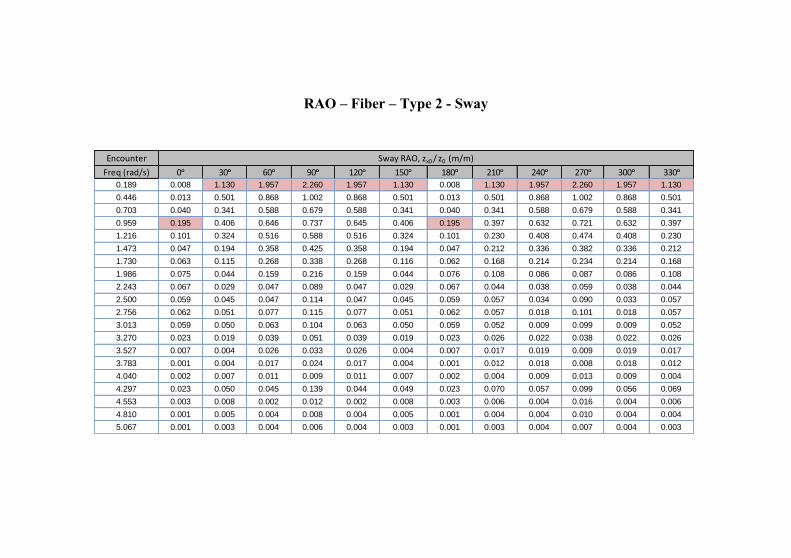
RAO – Fiber – Type 2 - Sway
Encounter
Freq (rad/s) 0ᵒ 30ᵒ 60ᵒ 90ᵒ 120ᵒ 150ᵒ 180ᵒ 210ᵒ 240ᵒ 270ᵒ 300ᵒ 330ᵒ
0.189 0.008 1.130 1.957 2.260 1.957 1.130 0.008 1.130 1.957 2.260 1.957 1.130
0.446 0.013 0.501 0.868 1.002 0.868 0.501 0.013 0.501 0.868 1.002 0.868 0.501
0.703 0.040 0.341 0.588 0.679 0.588 0.341 0.040 0.341 0.588 0.679 0.588 0.341
0.959 0.195 0.406 0.646 0.737 0.645 0.406 0.195 0.397 0.632 0.721 0.632 0.397
1.216 0.101 0.324 0.516 0.588 0.516 0.324 0.101 0.230 0.408 0.474 0.408 0.230
1.473 0.047 0.194 0.358 0.425 0.358 0.194 0.047 0.212 0.336 0.382 0.336 0.212
1.730 0.063 0.115 0.268 0.338 0.268 0.116 0.062 0.168 0.214 0.234 0.214 0.168
1.986 0.075 0.044 0.159 0.216 0.159 0.044 0.076 0.108 0.086 0.087 0.086 0.108
2.243 0.067 0.029 0.047 0.089 0.047 0.029 0.067 0.044 0.038 0.059 0.038 0.044
2.500 0.059 0.045 0.047 0.114 0.047 0.045 0.059 0.057 0.034 0.090 0.033 0.057
2.756 0.062 0.051 0.077 0.115 0.077 0.051 0.062 0.057 0.018 0.101 0.018 0.057
3.013 0.059 0.050 0.063 0.104 0.063 0.050 0.059 0.052 0.009 0.099 0.009 0.052
3.270 0.023 0.019 0.039 0.051 0.039 0.019 0.023 0.026 0.022 0.038 0.022 0.026
3.527 0.007 0.004 0.026 0.033 0.026 0.004 0.007 0.017 0.019 0.009 0.019 0.017
3.783 0.001 0.004 0.017 0.024 0.017 0.004 0.001 0.012 0.018 0.008 0.018 0.012
4.040 0.002 0.007 0.011 0.009 0.011 0.007 0.002 0.004 0.009 0.013 0.009 0.004
4.297 0.023 0.050 0.045 0.139 0.044 0.049 0.023 0.070 0.057 0.099 0.056 0.069
4.553 0.003 0.008 0.002 0.012 0.002 0.008 0.003 0.006 0.004 0.016 0.004 0.006
4.810 0.001 0.005 0.004 0.008 0.004 0.005 0.001 0.004 0.004 0.010 0.004 0.004
5.067 0.001 0.003 0.004 0.006 0.004 0.003 0.001 0.003 0.004 0.007 0.004 0.003
Sway RAO, zx0 / z0 (m/m)
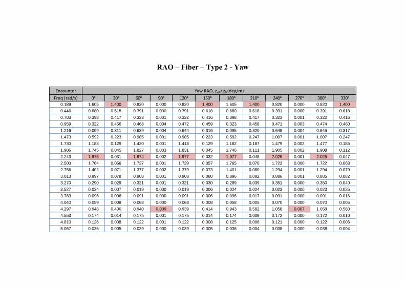
RAO – Fiber – Type 2 - Yaw
Encounter
Freq (rad/s) 0ᵒ 30ᵒ 60ᵒ 90ᵒ 120ᵒ 150ᵒ 180ᵒ 210ᵒ 240ᵒ 270ᵒ 300ᵒ 330ᵒ
0.189 1.605 1.400 0.820 0.000 0.820 1.400 1.605 1.400 0.820 0.000 0.820 1.400
0.446 0.680 0.618 0.391 0.000 0.391 0.618 0.680 0.618 0.391 0.000 0.391 0.618
0.703 0.398 0.417 0.323 0.001 0.322 0.416 0.398 0.417 0.323 0.001 0.322 0.416
0.959 0.322 0.456 0.468 0.004 0.472 0.459 0.323 0.458 0.471 0.003 0.474 0.460
1.216 0.099 0.311 0.639 0.004 0.644 0.316 0.095 0.320 0.648 0.004 0.645 0.317
1.473 0.592 0.223 0.985 0.001 0.985 0.223 0.592 0.247 1.007 0.001 1.007 0.247
1.730 1.183 0.129 1.420 0.001 1.418 0.129 1.182 0.187 1.479 0.002 1.477 0.186
1.986 1.745 0.045 1.827 0.003 1.831 0.045 1.746 0.111 1.905 0.002 1.908 0.112
2.243 1.975 0.031 1.974 0.002 1.977 0.032 1.977 0.048 2.025 0.001 2.025 0.047
2.500 1.764 0.056 1.737 0.001 1.739 0.057 1.765 0.070 1.723 0.000 1.722 0.068
2.756 1.402 0.071 1.377 0.002 1.379 0.073 1.401 0.080 1.294 0.001 1.294 0.079
3.013 0.897 0.078 0.908 0.001 0.908 0.080 0.896 0.082 0.886 0.001 0.885 0.082
3.270 0.290 0.029 0.321 0.001 0.321 0.030 0.289 0.039 0.351 0.000 0.350 0.040
3.527 0.024 0.007 0.019 0.000 0.019 0.006 0.024 0.024 0.023 0.000 0.023 0.025
3.783 0.096 0.006 0.091 0.000 0.091 0.006 0.096 0.017 0.091 0.000 0.091 0.016
4.040 0.059 0.008 0.068 0.000 0.068 0.008 0.058 0.005 0.070 0.000 0.070 0.005
4.297 0.948 0.406 0.940 0.009 0.939 0.414 0.943 0.582 1.058 0.007 1.058 0.580
4.553 0.174 0.014 0.175 0.001 0.175 0.014 0.174 0.009 0.172 0.000 0.172 0.010
4.810 0.126 0.008 0.122 0.001 0.122 0.008 0.125 0.006 0.121 0.000 0.122 0.006
5.067 0.036 0.005 0.039 0.000 0.039 0.005 0.036 0.004 0.038 0.000 0.038 0.004
Yaw RAO, zx0 / z0 (deg/m)

Attachment 3
SPECTRUM RESPONSE
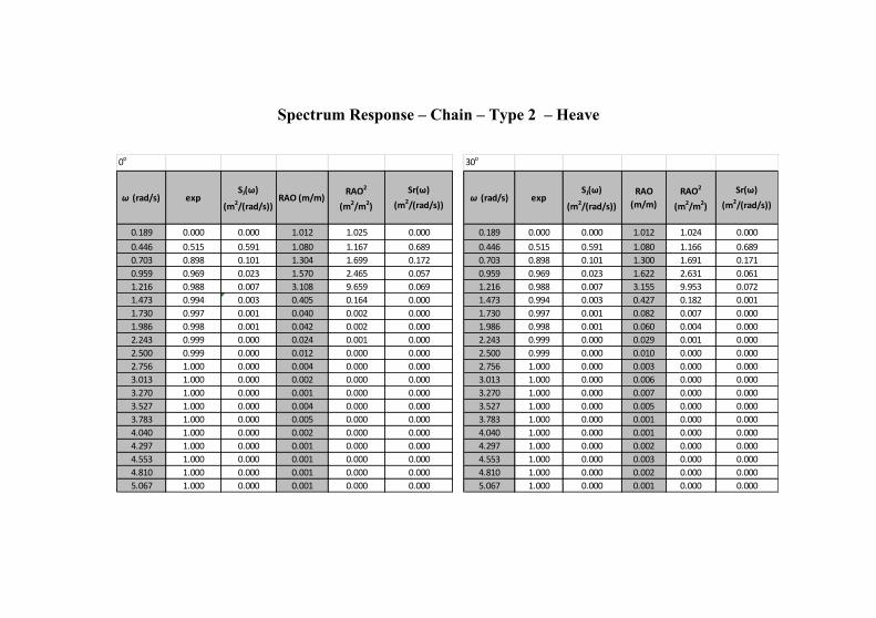
Spectrum Response – Chain – Type 2 – Heave
0o
ω (rad/s) expSJ(ω)
(m2/(rad/s))RAO (m/m)
RAO2
(m2/m2)
Sr(ω)
(m2/(rad/s))
0.189 0.000 0.000 1.012 1.025 0.000
0.446 0.515 0.591 1.080 1.167 0.689
0.703 0.898 0.101 1.304 1.699 0.172
0.959 0.969 0.023 1.570 2.465 0.057
1.216 0.988 0.007 3.108 9.659 0.069
1.473 0.994 0.003 0.405 0.164 0.000
1.730 0.997 0.001 0.040 0.002 0.000
1.986 0.998 0.001 0.042 0.002 0.000
2.243 0.999 0.000 0.024 0.001 0.000
2.500 0.999 0.000 0.012 0.000 0.000
2.756 1.000 0.000 0.004 0.000 0.000
3.013 1.000 0.000 0.002 0.000 0.000
3.270 1.000 0.000 0.001 0.000 0.000
3.527 1.000 0.000 0.004 0.000 0.000
3.783 1.000 0.000 0.005 0.000 0.000
4.040 1.000 0.000 0.002 0.000 0.000
4.297 1.000 0.000 0.001 0.000 0.000
4.553 1.000 0.000 0.001 0.000 0.000
4.810 1.000 0.000 0.001 0.000 0.000
5.067 1.000 0.000 0.001 0.000 0.000
30o
ω (rad/s) expSJ(ω)
(m2/(rad/s))
RAO
(m/m)
RAO2
(m2/m2)
Sr(ω)
(m2/(rad/s))
0.189 0.000 0.000 1.012 1.024 0.000
0.446 0.515 0.591 1.080 1.166 0.689
0.703 0.898 0.101 1.300 1.691 0.171
0.959 0.969 0.023 1.622 2.631 0.061
1.216 0.988 0.007 3.155 9.953 0.072
1.473 0.994 0.003 0.427 0.182 0.001
1.730 0.997 0.001 0.082 0.007 0.000
1.986 0.998 0.001 0.060 0.004 0.000
2.243 0.999 0.000 0.029 0.001 0.000
2.500 0.999 0.000 0.010 0.000 0.000
2.756 1.000 0.000 0.003 0.000 0.000
3.013 1.000 0.000 0.006 0.000 0.000
3.270 1.000 0.000 0.007 0.000 0.000
3.527 1.000 0.000 0.005 0.000 0.000
3.783 1.000 0.000 0.001 0.000 0.000
4.040 1.000 0.000 0.001 0.000 0.000
4.297 1.000 0.000 0.002 0.000 0.000
4.553 1.000 0.000 0.003 0.000 0.000
4.810 1.000 0.000 0.002 0.000 0.000
5.067 1.000 0.000 0.001 0.000 0.000
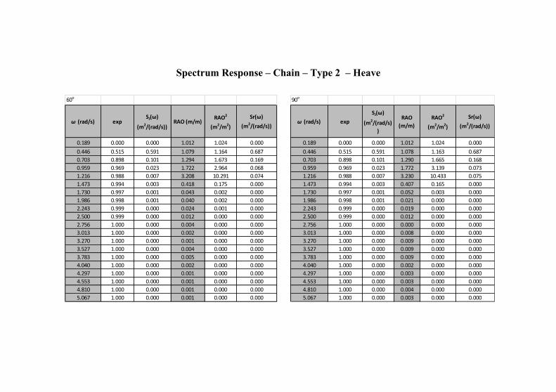
Spectrum Response – Chain – Type 2 – Heave
90o
ω (rad/s) exp
SJ(ω)
(m2/(rad/s)
)
RAO
(m/m)
RAO2
(m2/m2)
Sr(ω)
(m2/(rad/s))
0.189 0.000 0.000 1.012 1.024 0.000
0.446 0.515 0.591 1.078 1.163 0.687
0.703 0.898 0.101 1.290 1.665 0.168
0.959 0.969 0.023 1.772 3.139 0.073
1.216 0.988 0.007 3.230 10.433 0.075
1.473 0.994 0.003 0.407 0.165 0.000
1.730 0.997 0.001 0.052 0.003 0.000
1.986 0.998 0.001 0.021 0.000 0.000
2.243 0.999 0.000 0.019 0.000 0.000
2.500 0.999 0.000 0.012 0.000 0.000
2.756 1.000 0.000 0.000 0.000 0.000
3.013 1.000 0.000 0.008 0.000 0.000
3.270 1.000 0.000 0.009 0.000 0.000
3.527 1.000 0.000 0.009 0.000 0.000
3.783 1.000 0.000 0.009 0.000 0.000
4.040 1.000 0.000 0.002 0.000 0.000
4.297 1.000 0.000 0.003 0.000 0.000
4.553 1.000 0.000 0.003 0.000 0.000
4.810 1.000 0.000 0.004 0.000 0.000
5.067 1.000 0.000 0.003 0.000 0.000
60o
ω (rad/s) expSJ(ω)
(m2/(rad/s))RAO (m/m)
RAO2
(m2/m2)
Sr(ω)
(m2/(rad/s))
0.189 0.000 0.000 1.012 1.024 0.000
0.446 0.515 0.591 1.079 1.164 0.687
0.703 0.898 0.101 1.294 1.673 0.169
0.959 0.969 0.023 1.722 2.964 0.068
1.216 0.988 0.007 3.208 10.291 0.074
1.473 0.994 0.003 0.418 0.175 0.000
1.730 0.997 0.001 0.043 0.002 0.000
1.986 0.998 0.001 0.040 0.002 0.000
2.243 0.999 0.000 0.024 0.001 0.000
2.500 0.999 0.000 0.012 0.000 0.000
2.756 1.000 0.000 0.004 0.000 0.000
3.013 1.000 0.000 0.002 0.000 0.000
3.270 1.000 0.000 0.001 0.000 0.000
3.527 1.000 0.000 0.004 0.000 0.000
3.783 1.000 0.000 0.005 0.000 0.000
4.040 1.000 0.000 0.002 0.000 0.000
4.297 1.000 0.000 0.001 0.000 0.000
4.553 1.000 0.000 0.001 0.000 0.000
4.810 1.000 0.000 0.001 0.000 0.000
5.067 1.000 0.000 0.001 0.000 0.000
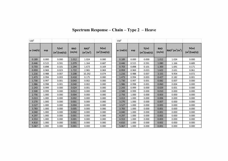
Spectrum Response – Chain – Type 2 – Heave
120o
ω (rad/s) expSJ(ω)
(m2/(rad/s))
RAO
(m/m)
RAO2
(m2/m2)
Sr(ω)
(m2/(rad/s))
0.189 0.000 0.000 1.012 1.024 0.000
0.446 0.515 0.591 1.079 1.164 0.687
0.703 0.898 0.101 1.294 1.673 0.169
0.959 0.969 0.023 1.722 2.965 0.069
1.216 0.988 0.007 3.208 10.292 0.074
1.473 0.994 0.003 0.418 0.175 0.000
1.730 0.997 0.001 0.043 0.002 0.000
1.986 0.998 0.001 0.040 0.002 0.000
2.243 0.999 0.000 0.024 0.001 0.000
2.500 0.999 0.000 0.012 0.000 0.000
2.756 1.000 0.000 0.004 0.000 0.000
3.013 1.000 0.000 0.002 0.000 0.000
3.270 1.000 0.000 0.001 0.000 0.000
3.527 1.000 0.000 0.004 0.000 0.000
3.783 1.000 0.000 0.005 0.000 0.000
4.040 1.000 0.000 0.002 0.000 0.000
4.297 1.000 0.000 0.001 0.000 0.000
4.553 1.000 0.000 0.001 0.000 0.000
4.810 1.000 0.000 0.001 0.000 0.000
5.067 1.000 0.000 0.001 0.000 0.000
150o
ω (rad/s) expSJ(ω)
(m2/(rad/s))
RAO
(m/m)RAO2 (m2/m2)
Sr(ω)
(m2/(rad/s))
0.189 0.000 0.000 1.012 1.024 0.000
0.446 0.515 0.591 1.080 1.166 0.689
0.703 0.898 0.101 1.300 1.691 0.171
0.959 0.969 0.023 1.622 2.631 0.061
1.216 0.988 0.007 3.155 9.954 0.072
1.473 0.994 0.003 0.427 0.182 0.001
1.730 0.997 0.001 0.082 0.007 0.000
1.986 0.998 0.001 0.060 0.004 0.000
2.243 0.999 0.000 0.029 0.001 0.000
2.500 0.999 0.000 0.010 0.000 0.000
2.756 1.000 0.000 0.003 0.000 0.000
3.013 1.000 0.000 0.006 0.000 0.000
3.270 1.000 0.000 0.007 0.000 0.000
3.527 1.000 0.000 0.005 0.000 0.000
3.783 1.000 0.000 0.001 0.000 0.000
4.040 1.000 0.000 0.001 0.000 0.000
4.297 1.000 0.000 0.002 0.000 0.000
4.553 1.000 0.000 0.003 0.000 0.000
4.810 1.000 0.000 0.002 0.000 0.000
5.067 1.000 0.000 0.001 0.000 0.000
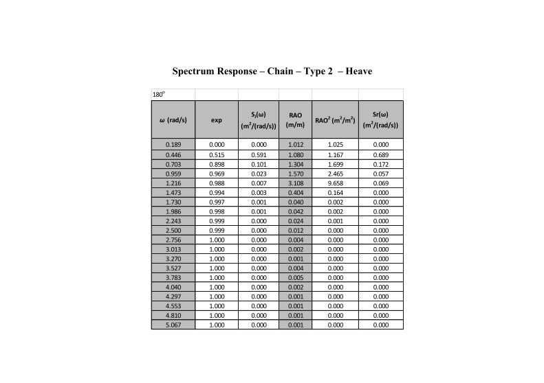
Spectrum Response – Chain – Type 2 – Heave
180o
ω (rad/s) expSJ(ω)
(m2/(rad/s))
RAO
(m/m)RAO2 (m2/m2)
Sr(ω)
(m2/(rad/s))
0.189 0.000 0.000 1.012 1.025 0.000
0.446 0.515 0.591 1.080 1.167 0.689
0.703 0.898 0.101 1.304 1.699 0.172
0.959 0.969 0.023 1.570 2.465 0.057
1.216 0.988 0.007 3.108 9.658 0.069
1.473 0.994 0.003 0.404 0.164 0.000
1.730 0.997 0.001 0.040 0.002 0.000
1.986 0.998 0.001 0.042 0.002 0.000
2.243 0.999 0.000 0.024 0.001 0.000
2.500 0.999 0.000 0.012 0.000 0.000
2.756 1.000 0.000 0.004 0.000 0.000
3.013 1.000 0.000 0.002 0.000 0.000
3.270 1.000 0.000 0.001 0.000 0.000
3.527 1.000 0.000 0.004 0.000 0.000
3.783 1.000 0.000 0.005 0.000 0.000
4.040 1.000 0.000 0.002 0.000 0.000
4.297 1.000 0.000 0.001 0.000 0.000
4.553 1.000 0.000 0.001 0.000 0.000
4.810 1.000 0.000 0.001 0.000 0.000
5.067 1.000 0.000 0.001 0.000 0.000
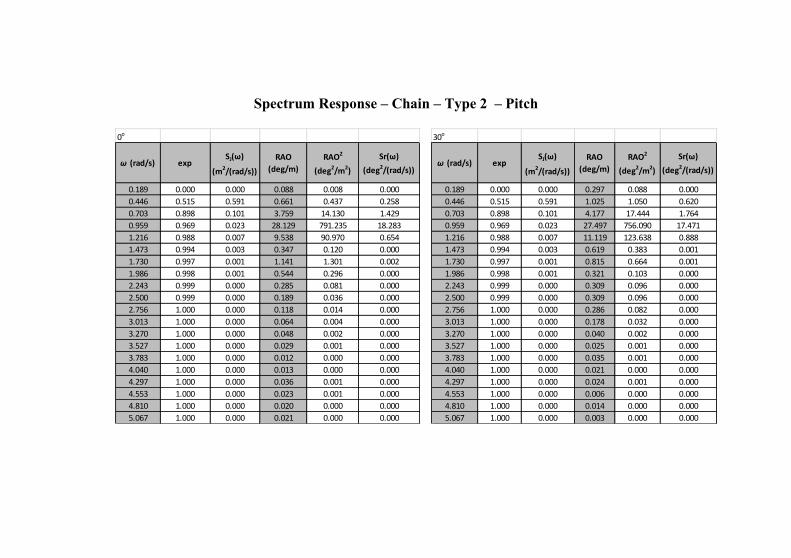
Spectrum Response – Chain – Type 2 – Pitch
0o
ω (rad/s) expSJ(ω)
(m2/(rad/s))
RAO
(deg/m)
RAO2
(deg2/m2)
Sr(ω)
(deg2/(rad/s))
0.189 0.000 0.000 0.088 0.008 0.000
0.446 0.515 0.591 0.661 0.437 0.258
0.703 0.898 0.101 3.759 14.130 1.429
0.959 0.969 0.023 28.129 791.235 18.283
1.216 0.988 0.007 9.538 90.970 0.654
1.473 0.994 0.003 0.347 0.120 0.000
1.730 0.997 0.001 1.141 1.301 0.002
1.986 0.998 0.001 0.544 0.296 0.000
2.243 0.999 0.000 0.285 0.081 0.000
2.500 0.999 0.000 0.189 0.036 0.000
2.756 1.000 0.000 0.118 0.014 0.000
3.013 1.000 0.000 0.064 0.004 0.000
3.270 1.000 0.000 0.048 0.002 0.000
3.527 1.000 0.000 0.029 0.001 0.000
3.783 1.000 0.000 0.012 0.000 0.000
4.040 1.000 0.000 0.013 0.000 0.000
4.297 1.000 0.000 0.036 0.001 0.000
4.553 1.000 0.000 0.023 0.001 0.000
4.810 1.000 0.000 0.020 0.000 0.000
5.067 1.000 0.000 0.021 0.000 0.000
30o
ω (rad/s) expSJ(ω)
(m2/(rad/s))
RAO
(deg/m)
RAO2
(deg2/m2)
Sr(ω)
(deg2/(rad/s))
0.189 0.000 0.000 0.297 0.088 0.000
0.446 0.515 0.591 1.025 1.050 0.620
0.703 0.898 0.101 4.177 17.444 1.764
0.959 0.969 0.023 27.497 756.090 17.471
1.216 0.988 0.007 11.119 123.638 0.888
1.473 0.994 0.003 0.619 0.383 0.001
1.730 0.997 0.001 0.815 0.664 0.001
1.986 0.998 0.001 0.321 0.103 0.000
2.243 0.999 0.000 0.309 0.096 0.000
2.500 0.999 0.000 0.309 0.096 0.000
2.756 1.000 0.000 0.286 0.082 0.000
3.013 1.000 0.000 0.178 0.032 0.000
3.270 1.000 0.000 0.040 0.002 0.000
3.527 1.000 0.000 0.025 0.001 0.000
3.783 1.000 0.000 0.035 0.001 0.000
4.040 1.000 0.000 0.021 0.000 0.000
4.297 1.000 0.000 0.024 0.001 0.000
4.553 1.000 0.000 0.006 0.000 0.000
4.810 1.000 0.000 0.014 0.000 0.000
5.067 1.000 0.000 0.003 0.000 0.000
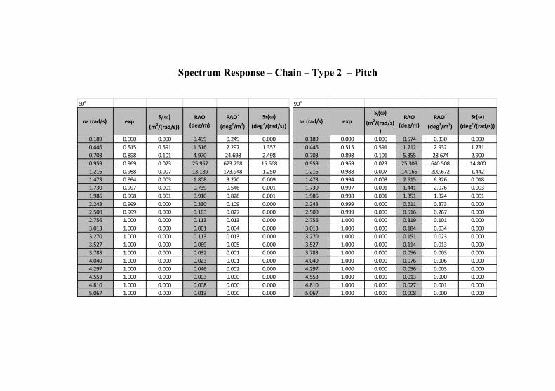
Spectrum Response – Chain – Type 2 – Pitch
60o
ω (rad/s) expSJ(ω)
(m2/(rad/s))
RAO
(deg/m)
RAO2
(deg2/m2)
Sr(ω)
(deg2/(rad/s))
0.189 0.000 0.000 0.499 0.249 0.000
0.446 0.515 0.591 1.516 2.297 1.357
0.703 0.898 0.101 4.970 24.698 2.498
0.959 0.969 0.023 25.957 673.758 15.568
1.216 0.988 0.007 13.189 173.948 1.250
1.473 0.994 0.003 1.808 3.270 0.009
1.730 0.997 0.001 0.739 0.546 0.001
1.986 0.998 0.001 0.910 0.828 0.001
2.243 0.999 0.000 0.330 0.109 0.000
2.500 0.999 0.000 0.163 0.027 0.000
2.756 1.000 0.000 0.113 0.013 0.000
3.013 1.000 0.000 0.061 0.004 0.000
3.270 1.000 0.000 0.113 0.013 0.000
3.527 1.000 0.000 0.069 0.005 0.000
3.783 1.000 0.000 0.032 0.001 0.000
4.040 1.000 0.000 0.023 0.001 0.000
4.297 1.000 0.000 0.046 0.002 0.000
4.553 1.000 0.000 0.003 0.000 0.000
4.810 1.000 0.000 0.008 0.000 0.000
5.067 1.000 0.000 0.013 0.000 0.000
90o
ω (rad/s) exp
SJ(ω)
(m2/(rad/s)
)
RAO
(deg/m)
RAO2
(deg2/m2)
Sr(ω)
(deg2/(rad/s))
0.189 0.000 0.000 0.574 0.330 0.000
0.446 0.515 0.591 1.712 2.932 1.731
0.703 0.898 0.101 5.355 28.674 2.900
0.959 0.969 0.023 25.308 640.508 14.800
1.216 0.988 0.007 14.166 200.672 1.442
1.473 0.994 0.003 2.515 6.326 0.018
1.730 0.997 0.001 1.441 2.076 0.003
1.986 0.998 0.001 1.351 1.824 0.001
2.243 0.999 0.000 0.611 0.373 0.000
2.500 0.999 0.000 0.516 0.267 0.000
2.756 1.000 0.000 0.319 0.101 0.000
3.013 1.000 0.000 0.184 0.034 0.000
3.270 1.000 0.000 0.151 0.023 0.000
3.527 1.000 0.000 0.114 0.013 0.000
3.783 1.000 0.000 0.056 0.003 0.000
4.040 1.000 0.000 0.076 0.006 0.000
4.297 1.000 0.000 0.056 0.003 0.000
4.553 1.000 0.000 0.013 0.000 0.000
4.810 1.000 0.000 0.027 0.001 0.000
5.067 1.000 0.000 0.008 0.000 0.000
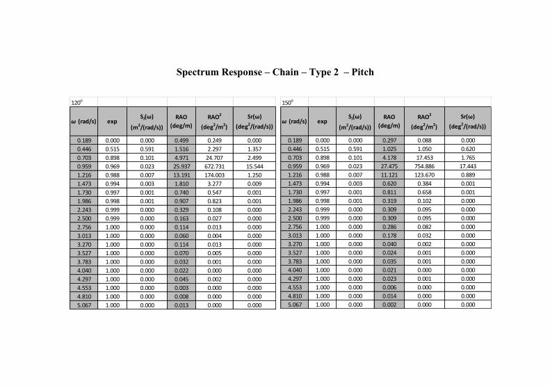
Spectrum Response – Chain – Type 2 – Pitch
120o
ω (rad/s) expSJ(ω)
(m2/(rad/s))
RAO
(deg/m)
RAO2
(deg2/m2)
Sr(ω)
(deg2/(rad/s))
0.189 0.000 0.000 0.499 0.249 0.000
0.446 0.515 0.591 1.516 2.297 1.357
0.703 0.898 0.101 4.971 24.707 2.499
0.959 0.969 0.023 25.937 672.731 15.544
1.216 0.988 0.007 13.191 174.003 1.250
1.473 0.994 0.003 1.810 3.277 0.009
1.730 0.997 0.001 0.740 0.547 0.001
1.986 0.998 0.001 0.907 0.823 0.001
2.243 0.999 0.000 0.329 0.108 0.000
2.500 0.999 0.000 0.163 0.027 0.000
2.756 1.000 0.000 0.114 0.013 0.000
3.013 1.000 0.000 0.060 0.004 0.000
3.270 1.000 0.000 0.114 0.013 0.000
3.527 1.000 0.000 0.070 0.005 0.000
3.783 1.000 0.000 0.032 0.001 0.000
4.040 1.000 0.000 0.022 0.000 0.000
4.297 1.000 0.000 0.045 0.002 0.000
4.553 1.000 0.000 0.003 0.000 0.000
4.810 1.000 0.000 0.008 0.000 0.000
5.067 1.000 0.000 0.013 0.000 0.000
150o
ω (rad/s) expSJ(ω)
(m2/(rad/s))
RAO
(deg/m)
RAO2
(deg2/m2)
Sr(ω)
(deg2/(rad/s))
0.189 0.000 0.000 0.297 0.088 0.000
0.446 0.515 0.591 1.025 1.050 0.620
0.703 0.898 0.101 4.178 17.453 1.765
0.959 0.969 0.023 27.475 754.886 17.443
1.216 0.988 0.007 11.121 123.670 0.889
1.473 0.994 0.003 0.620 0.384 0.001
1.730 0.997 0.001 0.811 0.658 0.001
1.986 0.998 0.001 0.319 0.102 0.000
2.243 0.999 0.000 0.309 0.095 0.000
2.500 0.999 0.000 0.309 0.095 0.000
2.756 1.000 0.000 0.286 0.082 0.000
3.013 1.000 0.000 0.178 0.032 0.000
3.270 1.000 0.000 0.040 0.002 0.000
3.527 1.000 0.000 0.024 0.001 0.000
3.783 1.000 0.000 0.035 0.001 0.000
4.040 1.000 0.000 0.021 0.000 0.000
4.297 1.000 0.000 0.023 0.001 0.000
4.553 1.000 0.000 0.006 0.000 0.000
4.810 1.000 0.000 0.014 0.000 0.000
5.067 1.000 0.000 0.002 0.000 0.000
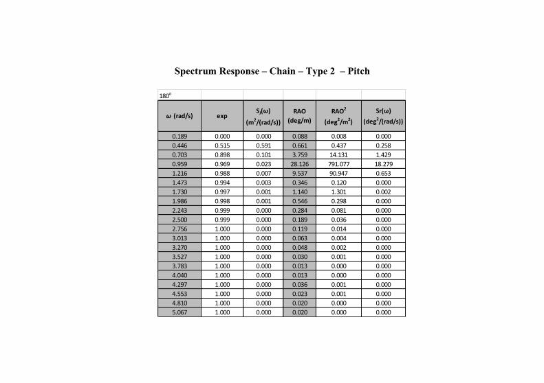
Spectrum Response – Chain – Type 2 – Pitch
180o
ω (rad/s) expSJ(ω)
(m2/(rad/s))
RAO
(deg/m)
RAO2
(deg2/m2)
Sr(ω)
(deg2/(rad/s))
0.189 0.000 0.000 0.088 0.008 0.000
0.446 0.515 0.591 0.661 0.437 0.258
0.703 0.898 0.101 3.759 14.131 1.429
0.959 0.969 0.023 28.126 791.077 18.279
1.216 0.988 0.007 9.537 90.947 0.653
1.473 0.994 0.003 0.346 0.120 0.000
1.730 0.997 0.001 1.140 1.301 0.002
1.986 0.998 0.001 0.546 0.298 0.000
2.243 0.999 0.000 0.284 0.081 0.000
2.500 0.999 0.000 0.189 0.036 0.000
2.756 1.000 0.000 0.119 0.014 0.000
3.013 1.000 0.000 0.063 0.004 0.000
3.270 1.000 0.000 0.048 0.002 0.000
3.527 1.000 0.000 0.030 0.001 0.000
3.783 1.000 0.000 0.013 0.000 0.000
4.040 1.000 0.000 0.013 0.000 0.000
4.297 1.000 0.000 0.036 0.001 0.000
4.553 1.000 0.000 0.023 0.001 0.000
4.810 1.000 0.000 0.020 0.000 0.000
5.067 1.000 0.000 0.020 0.000 0.000
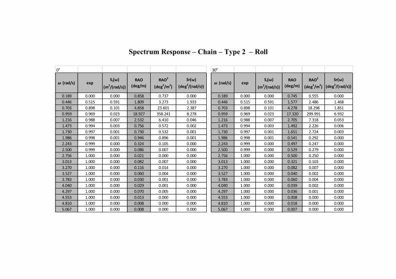
Spectrum Response – Chain – Type 2 – Roll
0o
ω (rad/s) expSJ(ω)
(m2/(rad/s))
RAO
(deg/m)
RAO2
(deg2/m2)
Sr(ω)
(deg2/(rad/s))
0.189 0.000 0.000 0.858 0.737 0.000
0.446 0.515 0.591 1.809 3.273 1.933
0.703 0.898 0.101 4.858 23.601 2.387
0.959 0.969 0.023 18.927 358.241 8.278
1.216 0.988 0.007 2.532 6.410 0.046
1.473 0.994 0.003 0.756 0.572 0.002
1.730 0.997 0.001 0.730 0.532 0.001
1.986 0.998 0.001 0.946 0.896 0.001
2.243 0.999 0.000 0.324 0.105 0.000
2.500 0.999 0.000 0.086 0.007 0.000
2.756 1.000 0.000 0.021 0.000 0.000
3.013 1.000 0.000 0.082 0.007 0.000
3.270 1.000 0.000 0.116 0.014 0.000
3.527 1.000 0.000 0.060 0.004 0.000
3.783 1.000 0.000 0.030 0.001 0.000
4.040 1.000 0.000 0.029 0.001 0.000
4.297 1.000 0.000 0.070 0.005 0.000
4.553 1.000 0.000 0.013 0.000 0.000
4.810 1.000 0.000 0.008 0.000 0.000
5.067 1.000 0.000 0.008 0.000 0.000
30o
ω (rad/s) expSJ(ω)
(m2/(rad/s))
RAO
(deg/m)
RAO2
(deg2/m2)
Sr(ω)
(deg2/(rad/s))
0.189 0.000 0.000 0.745 0.555 0.000
0.446 0.515 0.591 1.577 2.486 1.468
0.703 0.898 0.101 4.278 18.298 1.851
0.959 0.969 0.023 17.320 299.991 6.932
1.216 0.988 0.007 2.705 7.318 0.053
1.473 0.994 0.003 1.492 2.226 0.006
1.730 0.997 0.001 1.651 2.724 0.003
1.986 0.998 0.001 0.541 0.292 0.000
2.243 0.999 0.000 0.497 0.247 0.000
2.500 0.999 0.000 0.529 0.279 0.000
2.756 1.000 0.000 0.500 0.250 0.000
3.013 1.000 0.000 0.321 0.103 0.000
3.270 1.000 0.000 0.082 0.007 0.000
3.527 1.000 0.000 0.040 0.002 0.000
3.783 1.000 0.000 0.060 0.004 0.000
4.040 1.000 0.000 0.039 0.002 0.000
4.297 1.000 0.000 0.036 0.001 0.000
4.553 1.000 0.000 0.008 0.000 0.000
4.810 1.000 0.000 0.018 0.000 0.000
5.067 1.000 0.000 0.007 0.000 0.000
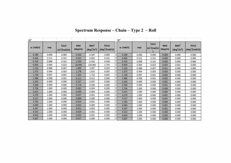
Spectrum Response – Chain – Type 2 – Roll
90o
ω (rad/s) exp
SJ(ω)
(m2/(rad/s)
)
RAO
(deg/m)
RAO2
(deg2/m2)
Sr(ω)
(deg2/(rad/s))
0.189 0.000 0.000 0.000 0.000 0.000
0.446 0.515 0.591 0.000 0.000 0.000
0.703 0.898 0.101 0.002 0.000 0.000
0.959 0.969 0.023 0.025 0.001 0.000
1.216 0.988 0.007 0.011 0.000 0.000
1.473 0.994 0.003 0.003 0.000 0.000
1.730 0.997 0.001 0.002 0.000 0.000
1.986 0.998 0.001 0.002 0.000 0.000
2.243 0.999 0.000 0.001 0.000 0.000
2.500 0.999 0.000 0.001 0.000 0.000
2.756 1.000 0.000 0.000 0.000 0.000
3.013 1.000 0.000 0.000 0.000 0.000
3.270 1.000 0.000 0.001 0.000 0.000
3.527 1.000 0.000 0.001 0.000 0.000
3.783 1.000 0.000 0.000 0.000 0.000
4.040 1.000 0.000 0.001 0.000 0.000
4.297 1.000 0.000 0.001 0.000 0.000
4.553 1.000 0.000 0.000 0.000 0.000
4.810 1.000 0.000 0.000 0.000 0.000
5.067 1.000 0.000 0.000 0.000 0.000
60o
ω (rad/s) expSJ(ω)
(m2/(rad/s))
RAO
(deg/m)
RAO2
(deg2/m2)
Sr(ω)
(deg2/(rad/s))
0.189 0.000 0.000 0.432 0.187 0.000
0.446 0.515 0.591 0.922 0.850 0.502
0.703 0.898 0.101 2.550 6.502 0.658
0.959 0.969 0.023 10.995 120.881 2.793
1.216 0.988 0.007 1.999 3.997 0.029
1.473 0.994 0.003 1.278 1.633 0.005
1.730 0.997 0.001 1.323 1.752 0.002
1.986 0.998 0.001 0.111 0.012 0.000
2.243 0.999 0.000 0.217 0.047 0.000
2.500 0.999 0.000 0.174 0.030 0.000
2.756 1.000 0.000 0.065 0.004 0.000
3.013 1.000 0.000 0.039 0.002 0.000
3.270 1.000 0.000 0.037 0.001 0.000
3.527 1.000 0.000 0.009 0.000 0.000
3.783 1.000 0.000 0.024 0.001 0.000
4.040 1.000 0.000 0.022 0.000 0.000
4.297 1.000 0.000 0.051 0.003 0.000
4.553 1.000 0.000 0.029 0.001 0.000
4.810 1.000 0.000 0.022 0.001 0.000
5.067 1.000 0.000 0.017 0.000 0.000
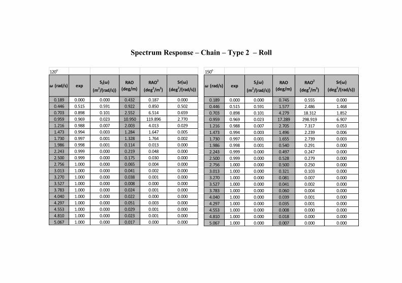
Spectrum Response – Chain – Type 2 – Roll
120o
ω (rad/s) expSJ(ω)
(m2/(rad/s))
RAO
(deg/m)
RAO2
(deg2/m2)
Sr(ω)
(deg2/(rad/s))
0.189 0.000 0.000 0.432 0.187 0.000
0.446 0.515 0.591 0.922 0.850 0.502
0.703 0.898 0.101 2.552 6.514 0.659
0.959 0.969 0.023 10.950 119.896 2.770
1.216 0.988 0.007 2.003 4.013 0.029
1.473 0.994 0.003 1.284 1.647 0.005
1.730 0.997 0.001 1.328 1.764 0.002
1.986 0.998 0.001 0.114 0.013 0.000
2.243 0.999 0.000 0.219 0.048 0.000
2.500 0.999 0.000 0.175 0.030 0.000
2.756 1.000 0.000 0.065 0.004 0.000
3.013 1.000 0.000 0.041 0.002 0.000
3.270 1.000 0.000 0.038 0.001 0.000
3.527 1.000 0.000 0.008 0.000 0.000
3.783 1.000 0.000 0.024 0.001 0.000
4.040 1.000 0.000 0.022 0.000 0.000
4.297 1.000 0.000 0.051 0.003 0.000
4.553 1.000 0.000 0.029 0.001 0.000
4.810 1.000 0.000 0.023 0.001 0.000
5.067 1.000 0.000 0.017 0.000 0.000
150o
ω (rad/s) expSJ(ω)
(m2/(rad/s))
RAO
(deg/m)
RAO2
(deg2/m2)
Sr(ω)
(deg2/(rad/s))
0.189 0.000 0.000 0.745 0.555 0.000
0.446 0.515 0.591 1.577 2.486 1.468
0.703 0.898 0.101 4.279 18.312 1.852
0.959 0.969 0.023 17.289 298.919 6.907
1.216 0.988 0.007 2.705 7.317 0.053
1.473 0.994 0.003 1.496 2.239 0.006
1.730 0.997 0.001 1.655 2.739 0.003
1.986 0.998 0.001 0.540 0.291 0.000
2.243 0.999 0.000 0.497 0.247 0.000
2.500 0.999 0.000 0.528 0.279 0.000
2.756 1.000 0.000 0.500 0.250 0.000
3.013 1.000 0.000 0.321 0.103 0.000
3.270 1.000 0.000 0.081 0.007 0.000
3.527 1.000 0.000 0.041 0.002 0.000
3.783 1.000 0.000 0.060 0.004 0.000
4.040 1.000 0.000 0.039 0.001 0.000
4.297 1.000 0.000 0.035 0.001 0.000
4.553 1.000 0.000 0.008 0.000 0.000
4.810 1.000 0.000 0.018 0.000 0.000
5.067 1.000 0.000 0.007 0.000 0.000
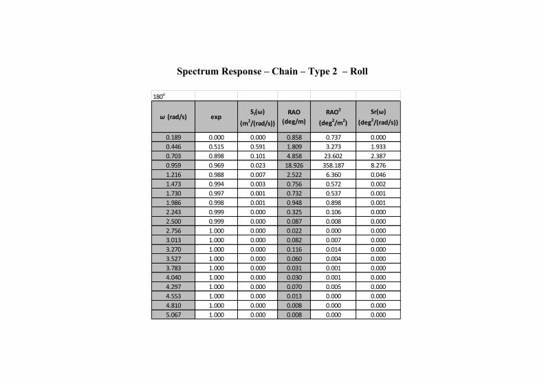
Spectrum Response – Chain – Type 2 – Roll
180o
ω (rad/s) expSJ(ω)
(m2/(rad/s))
RAO
(deg/m)
RAO2
(deg2/m2)
Sr(ω)
(deg2/(rad/s))
0.189 0.000 0.000 0.858 0.737 0.000
0.446 0.515 0.591 1.809 3.273 1.933
0.703 0.898 0.101 4.858 23.602 2.387
0.959 0.969 0.023 18.926 358.187 8.276
1.216 0.988 0.007 2.522 6.360 0.046
1.473 0.994 0.003 0.756 0.572 0.002
1.730 0.997 0.001 0.732 0.537 0.001
1.986 0.998 0.001 0.948 0.898 0.001
2.243 0.999 0.000 0.325 0.106 0.000
2.500 0.999 0.000 0.087 0.008 0.000
2.756 1.000 0.000 0.022 0.000 0.000
3.013 1.000 0.000 0.082 0.007 0.000
3.270 1.000 0.000 0.116 0.014 0.000
3.527 1.000 0.000 0.060 0.004 0.000
3.783 1.000 0.000 0.031 0.001 0.000
4.040 1.000 0.000 0.030 0.001 0.000
4.297 1.000 0.000 0.070 0.005 0.000
4.553 1.000 0.000 0.013 0.000 0.000
4.810 1.000 0.000 0.008 0.000 0.000
5.067 1.000 0.000 0.008 0.000 0.000
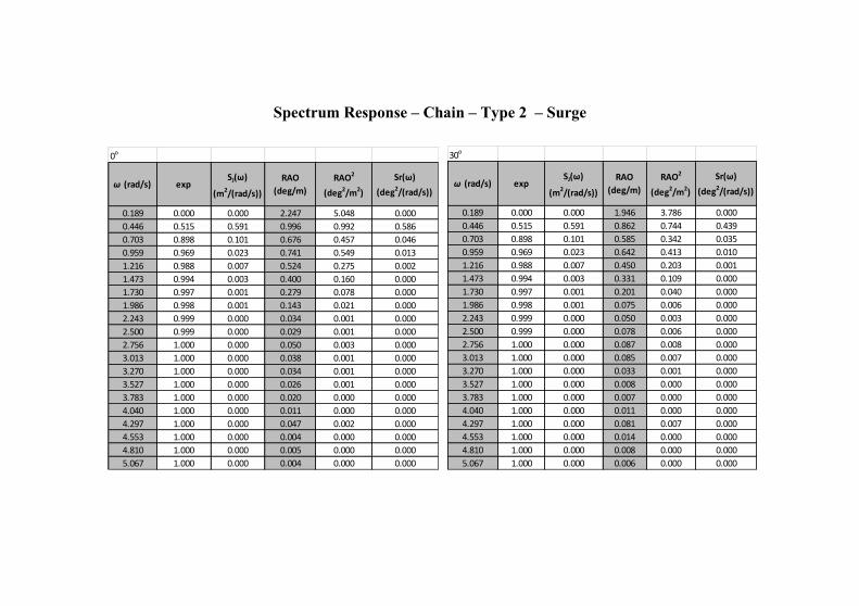
Spectrum Response – Chain – Type 2 – Surge
0o
ω (rad/s) expSJ(ω)
(m2/(rad/s))
RAO
(deg/m)
RAO2
(deg2/m2)
Sr(ω)
(deg2/(rad/s))
0.189 0.000 0.000 2.247 5.048 0.000
0.446 0.515 0.591 0.996 0.992 0.586
0.703 0.898 0.101 0.676 0.457 0.046
0.959 0.969 0.023 0.741 0.549 0.013
1.216 0.988 0.007 0.524 0.275 0.002
1.473 0.994 0.003 0.400 0.160 0.000
1.730 0.997 0.001 0.279 0.078 0.000
1.986 0.998 0.001 0.143 0.021 0.000
2.243 0.999 0.000 0.034 0.001 0.000
2.500 0.999 0.000 0.029 0.001 0.000
2.756 1.000 0.000 0.050 0.003 0.000
3.013 1.000 0.000 0.038 0.001 0.000
3.270 1.000 0.000 0.034 0.001 0.000
3.527 1.000 0.000 0.026 0.001 0.000
3.783 1.000 0.000 0.020 0.000 0.000
4.040 1.000 0.000 0.011 0.000 0.000
4.297 1.000 0.000 0.047 0.002 0.000
4.553 1.000 0.000 0.004 0.000 0.000
4.810 1.000 0.000 0.005 0.000 0.000
5.067 1.000 0.000 0.004 0.000 0.000
30o
ω (rad/s) expSJ(ω)
(m2/(rad/s))
RAO
(deg/m)
RAO2
(deg2/m2)
Sr(ω)
(deg2/(rad/s))
0.189 0.000 0.000 1.946 3.786 0.000
0.446 0.515 0.591 0.862 0.744 0.439
0.703 0.898 0.101 0.585 0.342 0.035
0.959 0.969 0.023 0.642 0.413 0.010
1.216 0.988 0.007 0.450 0.203 0.001
1.473 0.994 0.003 0.331 0.109 0.000
1.730 0.997 0.001 0.201 0.040 0.000
1.986 0.998 0.001 0.075 0.006 0.000
2.243 0.999 0.000 0.050 0.003 0.000
2.500 0.999 0.000 0.078 0.006 0.000
2.756 1.000 0.000 0.087 0.008 0.000
3.013 1.000 0.000 0.085 0.007 0.000
3.270 1.000 0.000 0.033 0.001 0.000
3.527 1.000 0.000 0.008 0.000 0.000
3.783 1.000 0.000 0.007 0.000 0.000
4.040 1.000 0.000 0.011 0.000 0.000
4.297 1.000 0.000 0.081 0.007 0.000
4.553 1.000 0.000 0.014 0.000 0.000
4.810 1.000 0.000 0.008 0.000 0.000
5.067 1.000 0.000 0.006 0.000 0.000
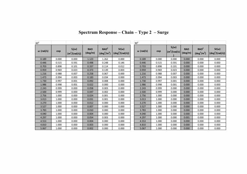
Spectrum Response – Chain – Type 2 – Surge
60o
ω (rad/s) expSJ(ω)
(m2/(rad/s))
RAO
(deg/m)
RAO2
(deg2/m2)
Sr(ω)
(deg2/(rad/s))
0.189 0.000 0.000 1.123 1.262 0.000
0.446 0.515 0.591 0.498 0.248 0.146
0.703 0.898 0.101 0.337 0.114 0.012
0.959 0.969 0.023 0.373 0.139 0.003
1.216 0.988 0.007 0.258 0.067 0.000
1.473 0.994 0.003 0.183 0.034 0.000
1.730 0.997 0.001 0.092 0.008 0.000
1.986 0.998 0.001 0.022 0.000 0.000
2.243 0.999 0.000 0.058 0.003 0.000
2.500 0.999 0.000 0.047 0.002 0.000
2.756 1.000 0.000 0.024 0.001 0.000
3.013 1.000 0.000 0.031 0.001 0.000
3.270 1.000 0.000 0.012 0.000 0.000
3.527 1.000 0.000 0.007 0.000 0.000
3.783 1.000 0.000 0.010 0.000 0.000
4.040 1.000 0.000 0.004 0.000 0.000
4.297 1.000 0.000 0.054 0.003 0.000
4.553 1.000 0.000 0.004 0.000 0.000
4.810 1.000 0.000 0.003 0.000 0.000
5.067 1.000 0.000 0.002 0.000 0.000
90o
ω (rad/s) exp
SJ(ω)
(m2/(rad/s)
)
RAO
(deg/m)
RAO2
(deg2/m2)
Sr(ω)
(deg2/(rad/s))
0.189 0.000 0.000 0.000 0.000 0.000
0.446 0.515 0.591 0.000 0.000 0.000
0.703 0.898 0.101 0.000 0.000 0.000
0.959 0.969 0.023 0.000 0.000 0.000
1.216 0.988 0.007 0.000 0.000 0.000
1.473 0.994 0.003 0.000 0.000 0.000
1.730 0.997 0.001 0.000 0.000 0.000
1.986 0.998 0.001 0.000 0.000 0.000
2.243 0.999 0.000 0.000 0.000 0.000
2.500 0.999 0.000 0.000 0.000 0.000
2.756 1.000 0.000 0.000 0.000 0.000
3.013 1.000 0.000 0.000 0.000 0.000
3.270 1.000 0.000 0.000 0.000 0.000
3.527 1.000 0.000 0.000 0.000 0.000
3.783 1.000 0.000 0.000 0.000 0.000
4.040 1.000 0.000 0.000 0.000 0.000
4.297 1.000 0.000 0.001 0.000 0.000
4.553 1.000 0.000 0.000 0.000 0.000
4.810 1.000 0.000 0.000 0.000 0.000
5.067 1.000 0.000 0.000 0.000 0.000
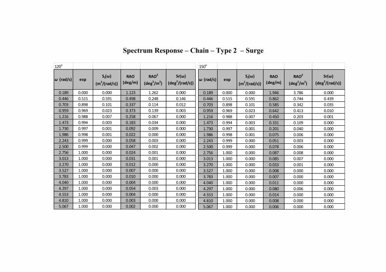
Spectrum Response – Chain – Type 2 – Surge
150o
ω (rad/s) expSJ(ω)
(m2/(rad/s))
RAO
(deg/m)
RAO2
(deg2/m2)
Sr(ω)
(deg2/(rad/s))
0.189 0.000 0.000 1.946 3.786 0.000
0.446 0.515 0.591 0.862 0.744 0.439
0.703 0.898 0.101 0.585 0.342 0.035
0.959 0.969 0.023 0.642 0.413 0.010
1.216 0.988 0.007 0.450 0.203 0.001
1.473 0.994 0.003 0.331 0.109 0.000
1.730 0.997 0.001 0.201 0.040 0.000
1.986 0.998 0.001 0.075 0.006 0.000
2.243 0.999 0.000 0.051 0.003 0.000
2.500 0.999 0.000 0.078 0.006 0.000
2.756 1.000 0.000 0.087 0.008 0.000
3.013 1.000 0.000 0.085 0.007 0.000
3.270 1.000 0.000 0.033 0.001 0.000
3.527 1.000 0.000 0.008 0.000 0.000
3.783 1.000 0.000 0.007 0.000 0.000
4.040 1.000 0.000 0.011 0.000 0.000
4.297 1.000 0.000 0.080 0.006 0.000
4.553 1.000 0.000 0.014 0.000 0.000
4.810 1.000 0.000 0.008 0.000 0.000
5.067 1.000 0.000 0.006 0.000 0.000
120o
ω (rad/s) expSJ(ω)
(m2/(rad/s))
RAO
(deg/m)
RAO2
(deg2/m2)
Sr(ω)
(deg2/(rad/s))
0.189 0.000 0.000 1.123 1.262 0.000
0.446 0.515 0.591 0.498 0.248 0.146
0.703 0.898 0.101 0.337 0.114 0.012
0.959 0.969 0.023 0.373 0.139 0.003
1.216 0.988 0.007 0.258 0.067 0.000
1.473 0.994 0.003 0.183 0.034 0.000
1.730 0.997 0.001 0.092 0.009 0.000
1.986 0.998 0.001 0.022 0.000 0.000
2.243 0.999 0.000 0.058 0.003 0.000
2.500 0.999 0.000 0.047 0.002 0.000
2.756 1.000 0.000 0.024 0.001 0.000
3.013 1.000 0.000 0.031 0.001 0.000
3.270 1.000 0.000 0.012 0.000 0.000
3.527 1.000 0.000 0.007 0.000 0.000
3.783 1.000 0.000 0.010 0.000 0.000
4.040 1.000 0.000 0.004 0.000 0.000
4.297 1.000 0.000 0.054 0.003 0.000
4.553 1.000 0.000 0.004 0.000 0.000
4.810 1.000 0.000 0.003 0.000 0.000
5.067 1.000 0.000 0.002 0.000 0.000
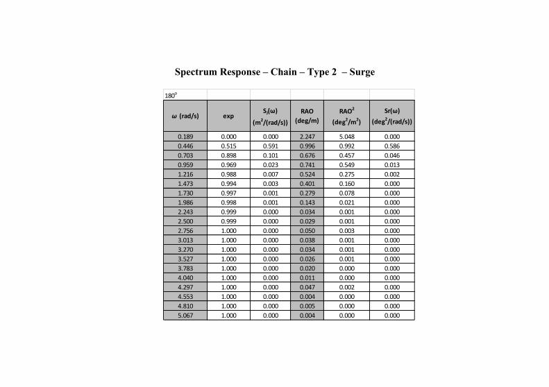
Spectrum Response – Chain – Type 2 – Surge
180o
ω (rad/s) expSJ(ω)
(m2/(rad/s))
RAO
(deg/m)
RAO2
(deg2/m2)
Sr(ω)
(deg2/(rad/s))
0.189 0.000 0.000 2.247 5.048 0.000
0.446 0.515 0.591 0.996 0.992 0.586
0.703 0.898 0.101 0.676 0.457 0.046
0.959 0.969 0.023 0.741 0.549 0.013
1.216 0.988 0.007 0.524 0.275 0.002
1.473 0.994 0.003 0.401 0.160 0.000
1.730 0.997 0.001 0.279 0.078 0.000
1.986 0.998 0.001 0.143 0.021 0.000
2.243 0.999 0.000 0.034 0.001 0.000
2.500 0.999 0.000 0.029 0.001 0.000
2.756 1.000 0.000 0.050 0.003 0.000
3.013 1.000 0.000 0.038 0.001 0.000
3.270 1.000 0.000 0.034 0.001 0.000
3.527 1.000 0.000 0.026 0.001 0.000
3.783 1.000 0.000 0.020 0.000 0.000
4.040 1.000 0.000 0.011 0.000 0.000
4.297 1.000 0.000 0.047 0.002 0.000
4.553 1.000 0.000 0.004 0.000 0.000
4.810 1.000 0.000 0.005 0.000 0.000
5.067 1.000 0.000 0.004 0.000 0.000
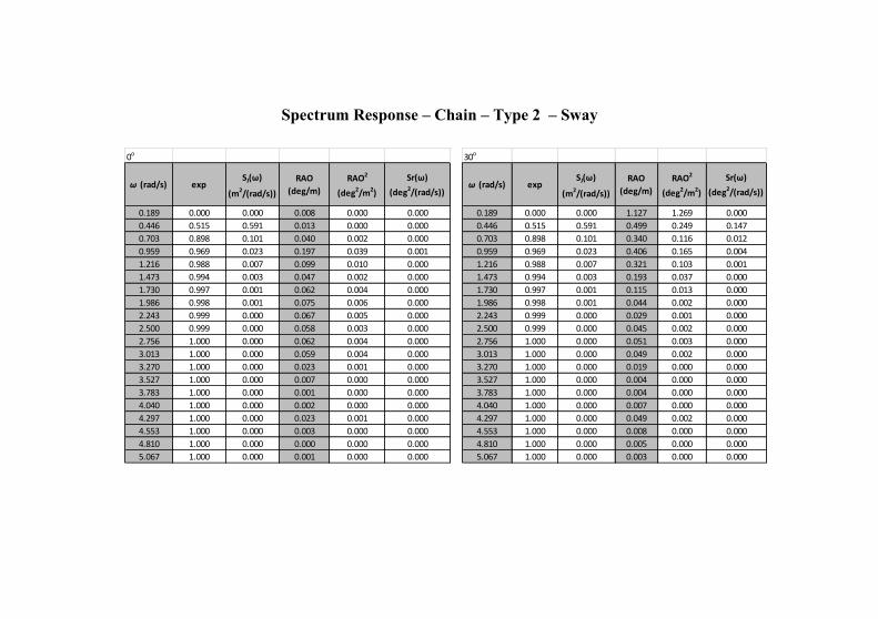
Spectrum Response – Chain – Type 2 – Sway
0o
ω (rad/s) expSJ(ω)
(m2/(rad/s))
RAO
(deg/m)
RAO2
(deg2/m2)
Sr(ω)
(deg2/(rad/s))
0.189 0.000 0.000 0.008 0.000 0.000
0.446 0.515 0.591 0.013 0.000 0.000
0.703 0.898 0.101 0.040 0.002 0.000
0.959 0.969 0.023 0.197 0.039 0.001
1.216 0.988 0.007 0.099 0.010 0.000
1.473 0.994 0.003 0.047 0.002 0.000
1.730 0.997 0.001 0.062 0.004 0.000
1.986 0.998 0.001 0.075 0.006 0.000
2.243 0.999 0.000 0.067 0.005 0.000
2.500 0.999 0.000 0.058 0.003 0.000
2.756 1.000 0.000 0.062 0.004 0.000
3.013 1.000 0.000 0.059 0.004 0.000
3.270 1.000 0.000 0.023 0.001 0.000
3.527 1.000 0.000 0.007 0.000 0.000
3.783 1.000 0.000 0.001 0.000 0.000
4.040 1.000 0.000 0.002 0.000 0.000
4.297 1.000 0.000 0.023 0.001 0.000
4.553 1.000 0.000 0.003 0.000 0.000
4.810 1.000 0.000 0.000 0.000 0.000
5.067 1.000 0.000 0.001 0.000 0.000
30o
ω (rad/s) expSJ(ω)
(m2/(rad/s))
RAO
(deg/m)
RAO2
(deg2/m2)
Sr(ω)
(deg2/(rad/s))
0.189 0.000 0.000 1.127 1.269 0.000
0.446 0.515 0.591 0.499 0.249 0.147
0.703 0.898 0.101 0.340 0.116 0.012
0.959 0.969 0.023 0.406 0.165 0.004
1.216 0.988 0.007 0.321 0.103 0.001
1.473 0.994 0.003 0.193 0.037 0.000
1.730 0.997 0.001 0.115 0.013 0.000
1.986 0.998 0.001 0.044 0.002 0.000
2.243 0.999 0.000 0.029 0.001 0.000
2.500 0.999 0.000 0.045 0.002 0.000
2.756 1.000 0.000 0.051 0.003 0.000
3.013 1.000 0.000 0.049 0.002 0.000
3.270 1.000 0.000 0.019 0.000 0.000
3.527 1.000 0.000 0.004 0.000 0.000
3.783 1.000 0.000 0.004 0.000 0.000
4.040 1.000 0.000 0.007 0.000 0.000
4.297 1.000 0.000 0.049 0.002 0.000
4.553 1.000 0.000 0.008 0.000 0.000
4.810 1.000 0.000 0.005 0.000 0.000
5.067 1.000 0.000 0.003 0.000 0.000
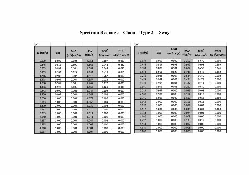
Spectrum Response – Chain – Type 2 – Sway
60o
ω (rad/s) expSJ(ω)
(m2/(rad/s))
RAO
(deg/m)
RAO2
(deg2/m2)
Sr(ω)
(deg2/(rad/s))
0.189 0.000 0.000 1.951 3.807 0.000
0.446 0.515 0.591 0.865 0.748 0.442
0.703 0.898 0.101 0.587 0.344 0.035
0.959 0.969 0.023 0.644 0.415 0.010
1.216 0.988 0.007 0.512 0.262 0.002
1.473 0.994 0.003 0.357 0.128 0.000
1.730 0.997 0.001 0.267 0.072 0.000
1.986 0.998 0.001 0.159 0.025 0.000
2.243 0.999 0.000 0.047 0.002 0.000
2.500 0.999 0.000 0.047 0.002 0.000
2.756 1.000 0.000 0.077 0.006 0.000
3.013 1.000 0.000 0.063 0.004 0.000
3.270 1.000 0.000 0.039 0.002 0.000
3.527 1.000 0.000 0.026 0.001 0.000
3.783 1.000 0.000 0.017 0.000 0.000
4.040 1.000 0.000 0.011 0.000 0.000
4.297 1.000 0.000 0.044 0.002 0.000
4.553 1.000 0.000 0.002 0.000 0.000
4.810 1.000 0.000 0.004 0.000 0.000
5.067 1.000 0.000 0.004 0.000 0.000
90o
ω (rad/s) exp
SJ(ω)
(m2/(rad/s)
)
RAO
(deg/m)
RAO2
(deg2/m2)
Sr(ω)
(deg2/(rad/s))
0.189 0.000 0.000 2.253 5.076 0.000
0.446 0.515 0.591 0.999 0.998 0.589
0.703 0.898 0.101 0.677 0.459 0.046
0.959 0.969 0.023 0.735 0.540 0.012
1.216 0.988 0.007 0.584 0.340 0.002
1.473 0.994 0.003 0.424 0.179 0.000
1.730 0.997 0.001 0.337 0.114 0.000
1.986 0.998 0.001 0.215 0.046 0.000
2.243 0.999 0.000 0.089 0.008 0.000
2.500 0.999 0.000 0.114 0.013 0.000
2.756 1.000 0.000 0.115 0.013 0.000
3.013 1.000 0.000 0.103 0.011 0.000
3.270 1.000 0.000 0.051 0.003 0.000
3.527 1.000 0.000 0.033 0.001 0.000
3.783 1.000 0.000 0.024 0.001 0.000
4.040 1.000 0.000 0.009 0.000 0.000
4.297 1.000 0.000 0.138 0.019 0.000
4.553 1.000 0.000 0.012 0.000 0.000
4.810 1.000 0.000 0.008 0.000 0.000
5.067 1.000 0.000 0.006 0.000 0.000
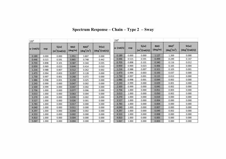
Spectrum Response – Chain – Type 2 – Sway
120o
ω (rad/s) expSJ(ω)
(m2/(rad/s))
RAO
(deg/m)
RAO2
(deg2/m2)
Sr(ω)
(deg2/(rad/s))
0.189 0.000 0.000 1.951 3.807 0.000
0.446 0.515 0.591 0.865 0.748 0.442
0.703 0.898 0.101 0.587 0.344 0.035
0.959 0.969 0.023 0.644 0.414 0.010
1.216 0.988 0.007 0.512 0.262 0.002
1.473 0.994 0.003 0.357 0.128 0.000
1.730 0.997 0.001 0.268 0.072 0.000
1.986 0.998 0.001 0.159 0.025 0.000
2.243 0.999 0.000 0.047 0.002 0.000
2.500 0.999 0.000 0.047 0.002 0.000
2.756 1.000 0.000 0.077 0.006 0.000
3.013 1.000 0.000 0.063 0.004 0.000
3.270 1.000 0.000 0.039 0.002 0.000
3.527 1.000 0.000 0.026 0.001 0.000
3.783 1.000 0.000 0.017 0.000 0.000
4.040 1.000 0.000 0.011 0.000 0.000
4.297 1.000 0.000 0.044 0.002 0.000
4.553 1.000 0.000 0.002 0.000 0.000
4.810 1.000 0.000 0.004 0.000 0.000
5.067 1.000 0.000 0.004 0.000 0.000
150o
ω (rad/s) expSJ(ω)
(m2/(rad/s))
RAO
(deg/m)
RAO2
(deg2/m2)
Sr(ω)
(deg2/(rad/s))
0.189 0.000 0.000 1.127 1.269 0.000
0.446 0.515 0.591 0.499 0.249 0.147
0.703 0.898 0.101 0.340 0.116 0.012
0.959 0.969 0.023 0.406 0.165 0.004
1.216 0.988 0.007 0.321 0.103 0.001
1.473 0.994 0.003 0.193 0.037 0.000
1.730 0.997 0.001 0.115 0.013 0.000
1.986 0.998 0.001 0.044 0.002 0.000
2.243 0.999 0.000 0.029 0.001 0.000
2.500 0.999 0.000 0.045 0.002 0.000
2.756 1.000 0.000 0.051 0.003 0.000
3.013 1.000 0.000 0.050 0.002 0.000
3.270 1.000 0.000 0.019 0.000 0.000
3.527 1.000 0.000 0.004 0.000 0.000
3.783 1.000 0.000 0.004 0.000 0.000
4.040 1.000 0.000 0.007 0.000 0.000
4.297 1.000 0.000 0.049 0.002 0.000
4.553 1.000 0.000 0.008 0.000 0.000
4.810 1.000 0.000 0.005 0.000 0.000
5.067 1.000 0.000 0.003 0.000 0.000
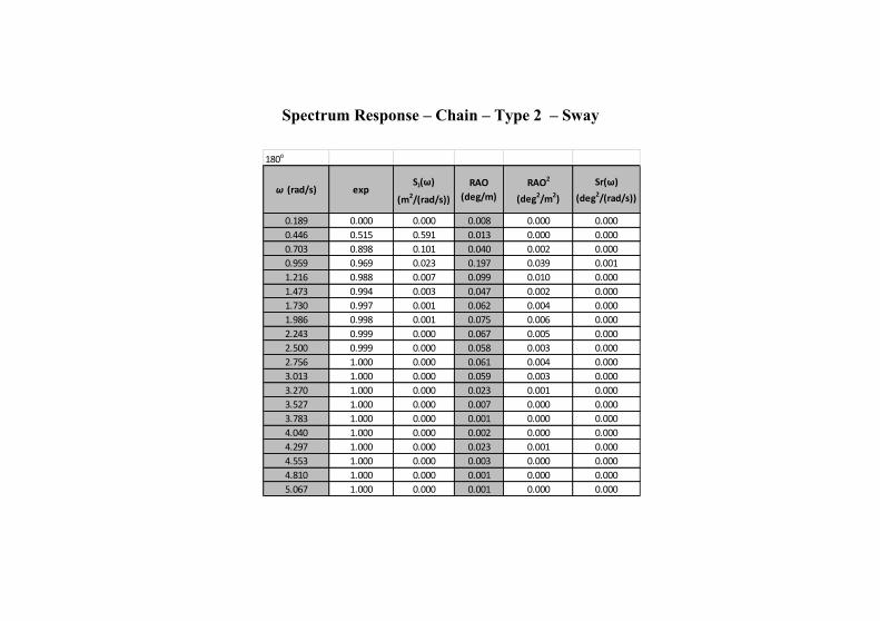
Spectrum Response – Chain – Type 2 – Sway
180o
ω (rad/s) expSJ(ω)
(m2/(rad/s))
RAO
(deg/m)
RAO2
(deg2/m2)
Sr(ω)
(deg2/(rad/s))
0.189 0.000 0.000 0.008 0.000 0.000
0.446 0.515 0.591 0.013 0.000 0.000
0.703 0.898 0.101 0.040 0.002 0.000
0.959 0.969 0.023 0.197 0.039 0.001
1.216 0.988 0.007 0.099 0.010 0.000
1.473 0.994 0.003 0.047 0.002 0.000
1.730 0.997 0.001 0.062 0.004 0.000
1.986 0.998 0.001 0.075 0.006 0.000
2.243 0.999 0.000 0.067 0.005 0.000
2.500 0.999 0.000 0.058 0.003 0.000
2.756 1.000 0.000 0.061 0.004 0.000
3.013 1.000 0.000 0.059 0.003 0.000
3.270 1.000 0.000 0.023 0.001 0.000
3.527 1.000 0.000 0.007 0.000 0.000
3.783 1.000 0.000 0.001 0.000 0.000
4.040 1.000 0.000 0.002 0.000 0.000
4.297 1.000 0.000 0.023 0.001 0.000
4.553 1.000 0.000 0.003 0.000 0.000
4.810 1.000 0.000 0.001 0.000 0.000
5.067 1.000 0.000 0.001 0.000 0.000
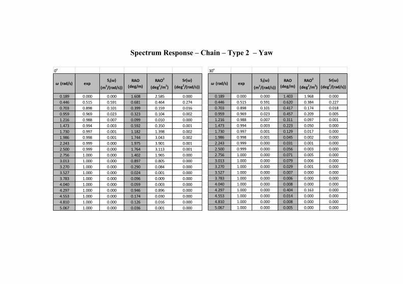
Spectrum Response – Chain – Type 2 – Yaw
30o
ω (rad/s) expSJ(ω)
(m2/(rad/s))
RAO
(deg/m)
RAO2
(deg2/m2)
Sr(ω)
(deg2/(rad/s))
0.189 0.000 0.000 1.403 1.968 0.000
0.446 0.515 0.591 0.620 0.384 0.227
0.703 0.898 0.101 0.417 0.174 0.018
0.959 0.969 0.023 0.457 0.209 0.005
1.216 0.988 0.007 0.311 0.097 0.001
1.473 0.994 0.003 0.223 0.050 0.000
1.730 0.997 0.001 0.129 0.017 0.000
1.986 0.998 0.001 0.045 0.002 0.000
2.243 0.999 0.000 0.031 0.001 0.000
2.500 0.999 0.000 0.056 0.003 0.000
2.756 1.000 0.000 0.071 0.005 0.000
3.013 1.000 0.000 0.079 0.006 0.000
3.270 1.000 0.000 0.029 0.001 0.000
3.527 1.000 0.000 0.007 0.000 0.000
3.783 1.000 0.000 0.006 0.000 0.000
4.040 1.000 0.000 0.008 0.000 0.000
4.297 1.000 0.000 0.404 0.163 0.000
4.553 1.000 0.000 0.014 0.000 0.000
4.810 1.000 0.000 0.008 0.000 0.000
5.067 1.000 0.000 0.005 0.000 0.000
0o
ω (rad/s) expSJ(ω)
(m2/(rad/s))
RAO
(deg/m)
RAO2
(deg2/m2)
Sr(ω)
(deg2/(rad/s))
0.189 0.000 0.000 1.608 2.585 0.000
0.446 0.515 0.591 0.681 0.464 0.274
0.703 0.898 0.101 0.399 0.159 0.016
0.959 0.969 0.023 0.323 0.104 0.002
1.216 0.988 0.007 0.099 0.010 0.000
1.473 0.994 0.003 0.592 0.350 0.001
1.730 0.997 0.001 1.182 1.398 0.002
1.986 0.998 0.001 1.744 3.043 0.002
2.243 0.999 0.000 1.975 3.901 0.001
2.500 0.999 0.000 1.764 3.113 0.001
2.756 1.000 0.000 1.402 1.965 0.000
3.013 1.000 0.000 0.897 0.805 0.000
3.270 1.000 0.000 0.290 0.084 0.000
3.527 1.000 0.000 0.024 0.001 0.000
3.783 1.000 0.000 0.096 0.009 0.000
4.040 1.000 0.000 0.059 0.003 0.000
4.297 1.000 0.000 0.946 0.896 0.000
4.553 1.000 0.000 0.174 0.030 0.000
4.810 1.000 0.000 0.126 0.016 0.000
5.067 1.000 0.000 0.036 0.001 0.000
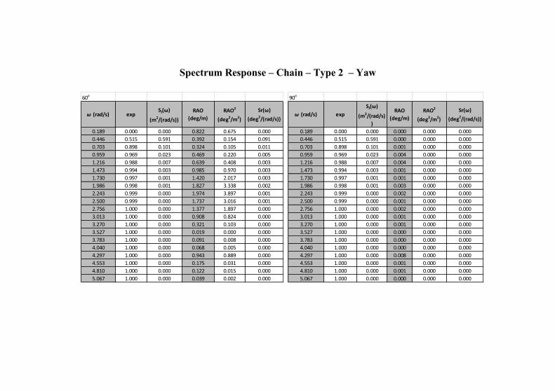
Spectrum Response – Chain – Type 2 – Yaw
60o
ω (rad/s) expSJ(ω)
(m2/(rad/s))
RAO
(deg/m)
RAO2
(deg2/m2)
Sr(ω)
(deg2/(rad/s))
0.189 0.000 0.000 0.822 0.675 0.000
0.446 0.515 0.591 0.392 0.154 0.091
0.703 0.898 0.101 0.324 0.105 0.011
0.959 0.969 0.023 0.469 0.220 0.005
1.216 0.988 0.007 0.639 0.408 0.003
1.473 0.994 0.003 0.985 0.970 0.003
1.730 0.997 0.001 1.420 2.017 0.003
1.986 0.998 0.001 1.827 3.338 0.002
2.243 0.999 0.000 1.974 3.897 0.001
2.500 0.999 0.000 1.737 3.016 0.001
2.756 1.000 0.000 1.377 1.897 0.000
3.013 1.000 0.000 0.908 0.824 0.000
3.270 1.000 0.000 0.321 0.103 0.000
3.527 1.000 0.000 0.019 0.000 0.000
3.783 1.000 0.000 0.091 0.008 0.000
4.040 1.000 0.000 0.068 0.005 0.000
4.297 1.000 0.000 0.943 0.889 0.000
4.553 1.000 0.000 0.175 0.031 0.000
4.810 1.000 0.000 0.122 0.015 0.000
5.067 1.000 0.000 0.039 0.002 0.000
90o
ω (rad/s) exp
SJ(ω)
(m2/(rad/s)
)
RAO
(deg/m)
RAO2
(deg2/m2)
Sr(ω)
(deg2/(rad/s))
0.189 0.000 0.000 0.000 0.000 0.000
0.446 0.515 0.591 0.000 0.000 0.000
0.703 0.898 0.101 0.001 0.000 0.000
0.959 0.969 0.023 0.004 0.000 0.000
1.216 0.988 0.007 0.004 0.000 0.000
1.473 0.994 0.003 0.001 0.000 0.000
1.730 0.997 0.001 0.001 0.000 0.000
1.986 0.998 0.001 0.003 0.000 0.000
2.243 0.999 0.000 0.002 0.000 0.000
2.500 0.999 0.000 0.001 0.000 0.000
2.756 1.000 0.000 0.002 0.000 0.000
3.013 1.000 0.000 0.001 0.000 0.000
3.270 1.000 0.000 0.001 0.000 0.000
3.527 1.000 0.000 0.000 0.000 0.000
3.783 1.000 0.000 0.000 0.000 0.000
4.040 1.000 0.000 0.000 0.000 0.000
4.297 1.000 0.000 0.008 0.000 0.000
4.553 1.000 0.000 0.001 0.000 0.000
4.810 1.000 0.000 0.001 0.000 0.000
5.067 1.000 0.000 0.000 0.000 0.000
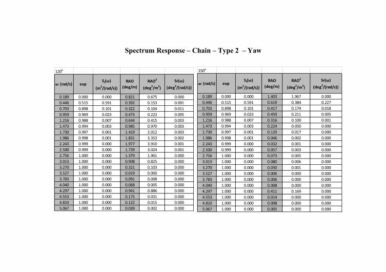
Spectrum Response – Chain – Type 2 – Yaw
150o
ω (rad/s) expSJ(ω)
(m2/(rad/s))
RAO
(deg/m)
RAO2
(deg2/m2)
Sr(ω)
(deg2/(rad/s))
0.189 0.000 0.000 1.403 1.967 0.000
0.446 0.515 0.591 0.619 0.384 0.227
0.703 0.898 0.101 0.417 0.174 0.018
0.959 0.969 0.023 0.459 0.211 0.005
1.216 0.988 0.007 0.316 0.100 0.001
1.473 0.994 0.003 0.224 0.050 0.000
1.730 0.997 0.001 0.129 0.017 0.000
1.986 0.998 0.001 0.046 0.002 0.000
2.243 0.999 0.000 0.032 0.001 0.000
2.500 0.999 0.000 0.057 0.003 0.000
2.756 1.000 0.000 0.073 0.005 0.000
3.013 1.000 0.000 0.080 0.006 0.000
3.270 1.000 0.000 0.030 0.001 0.000
3.527 1.000 0.000 0.006 0.000 0.000
3.783 1.000 0.000 0.006 0.000 0.000
4.040 1.000 0.000 0.008 0.000 0.000
4.297 1.000 0.000 0.411 0.169 0.000
4.553 1.000 0.000 0.014 0.000 0.000
4.810 1.000 0.000 0.008 0.000 0.000
5.067 1.000 0.000 0.005 0.000 0.000
120o
ω (rad/s) expSJ(ω)
(m2/(rad/s))
RAO
(deg/m)
RAO2
(deg2/m2)
Sr(ω)
(deg2/(rad/s))
0.189 0.000 0.000 0.821 0.675 0.000
0.446 0.515 0.591 0.392 0.153 0.091
0.703 0.898 0.101 0.322 0.104 0.011
0.959 0.969 0.023 0.473 0.223 0.005
1.216 0.988 0.007 0.644 0.415 0.003
1.473 0.994 0.003 0.985 0.970 0.003
1.730 0.997 0.001 1.419 2.012 0.003
1.986 0.998 0.001 1.831 3.353 0.002
2.243 0.999 0.000 1.977 3.910 0.001
2.500 0.999 0.000 1.739 3.024 0.001
2.756 1.000 0.000 1.379 1.901 0.000
3.013 1.000 0.000 0.908 0.825 0.000
3.270 1.000 0.000 0.321 0.103 0.000
3.527 1.000 0.000 0.019 0.000 0.000
3.783 1.000 0.000 0.091 0.008 0.000
4.040 1.000 0.000 0.068 0.005 0.000
4.297 1.000 0.000 0.941 0.886 0.000
4.553 1.000 0.000 0.175 0.031 0.000
4.810 1.000 0.000 0.122 0.015 0.000
5.067 1.000 0.000 0.039 0.002 0.000
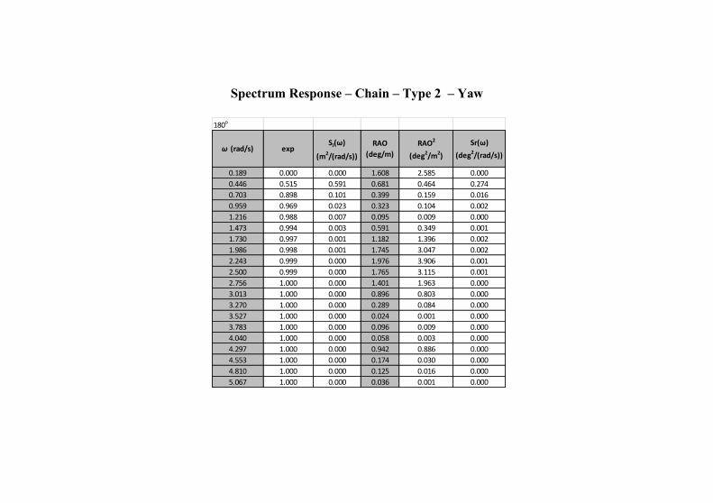
Spectrum Response – Chain – Type 2 – Yaw
180o
ω (rad/s) expSJ(ω)
(m2/(rad/s))
RAO
(deg/m)
RAO2
(deg2/m2)
Sr(ω)
(deg2/(rad/s))
0.189 0.000 0.000 1.608 2.585 0.000
0.446 0.515 0.591 0.681 0.464 0.274
0.703 0.898 0.101 0.399 0.159 0.016
0.959 0.969 0.023 0.323 0.104 0.002
1.216 0.988 0.007 0.095 0.009 0.000
1.473 0.994 0.003 0.591 0.349 0.001
1.730 0.997 0.001 1.182 1.396 0.002
1.986 0.998 0.001 1.745 3.047 0.002
2.243 0.999 0.000 1.976 3.906 0.001
2.500 0.999 0.000 1.765 3.115 0.001
2.756 1.000 0.000 1.401 1.963 0.000
3.013 1.000 0.000 0.896 0.803 0.000
3.270 1.000 0.000 0.289 0.084 0.000
3.527 1.000 0.000 0.024 0.001 0.000
3.783 1.000 0.000 0.096 0.009 0.000
4.040 1.000 0.000 0.058 0.003 0.000
4.297 1.000 0.000 0.942 0.886 0.000
4.553 1.000 0.000 0.174 0.030 0.000
4.810 1.000 0.000 0.125 0.016 0.000
5.067 1.000 0.000 0.036 0.001 0.000
Attachment 4
AQWA HYDROSTATIC RESULTS
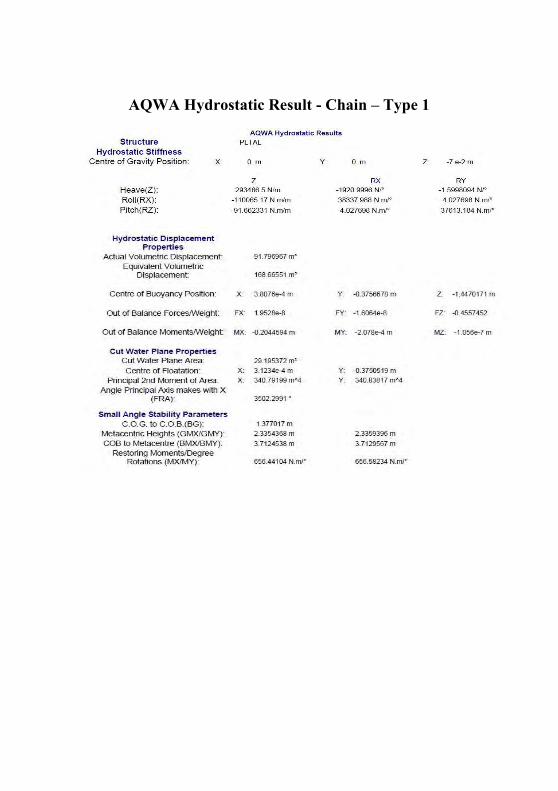
AQWA Hydrostatic Result - Chain – Type 1
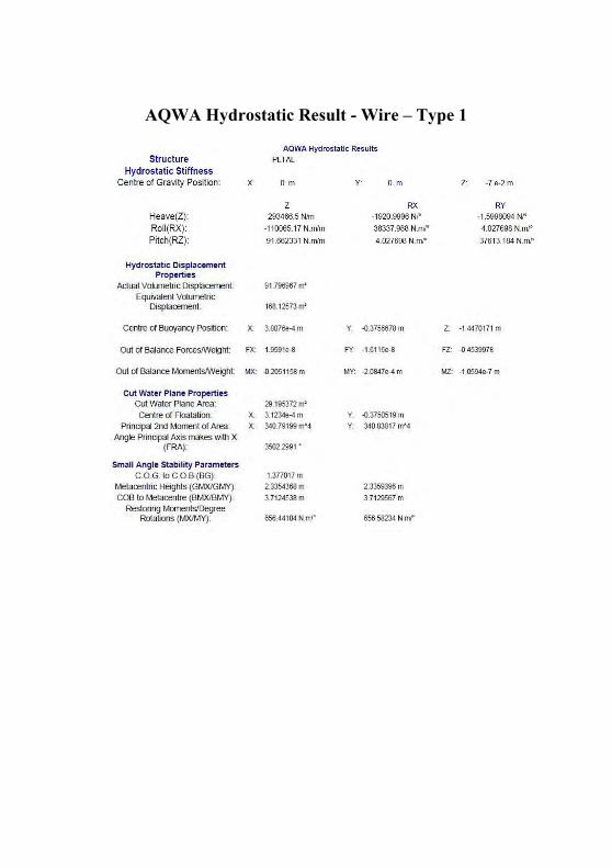
AQWA Hydrostatic Result - Wire – Type 1
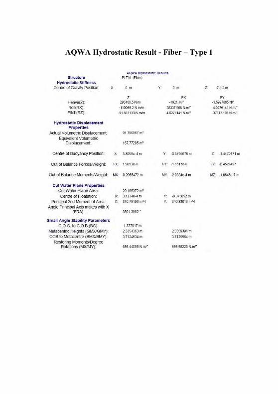
AQWA Hydrostatic Result - Fiber – Type 1
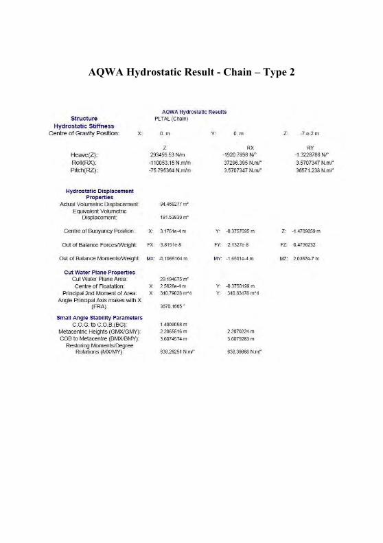
AQWA Hydrostatic Result - Chain – Type 2
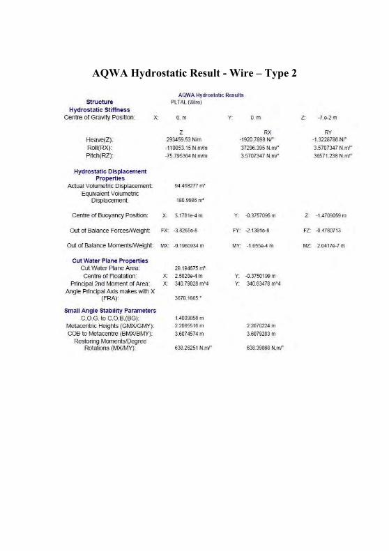
AQWA Hydrostatic Result - Wire – Type 2
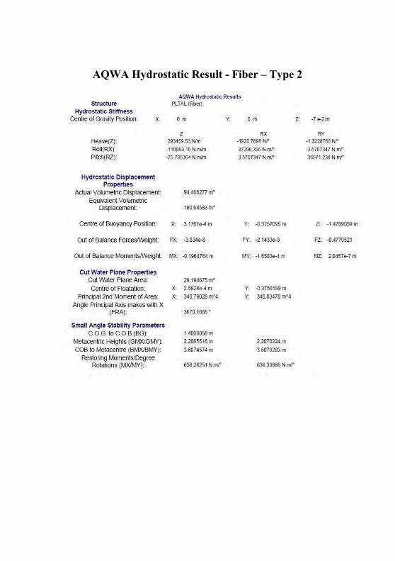
AQWA Hydrostatic Result - Fiber – Type 2

Attachment 5
SOFTWARE SCREENSHOT
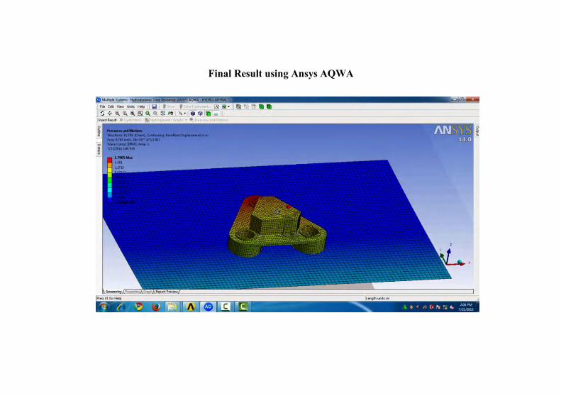
Final Result using Ansys AQWA
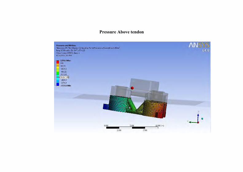
Pressure Above tendon
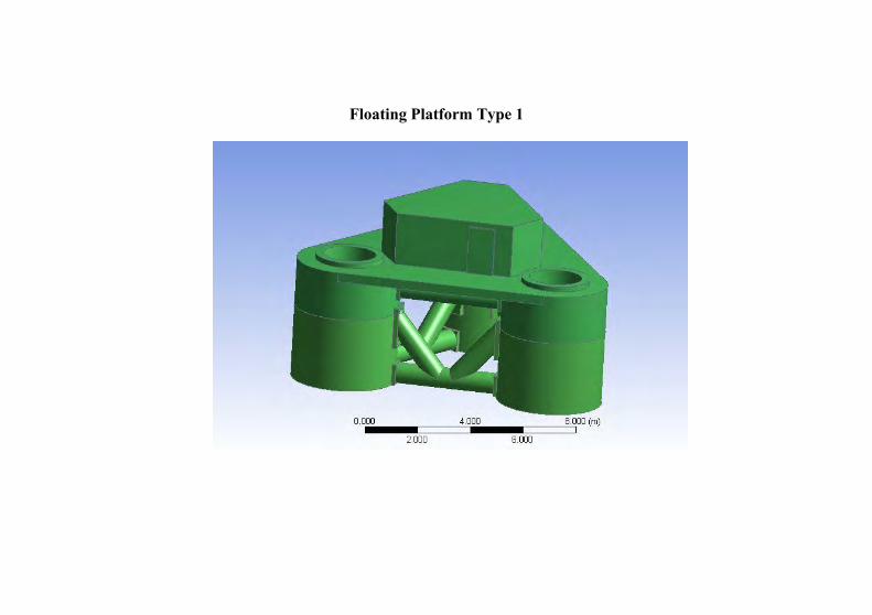
Floating Platform Type 1
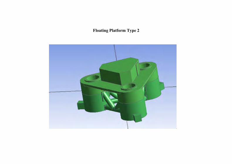
Floating Platform Type 2
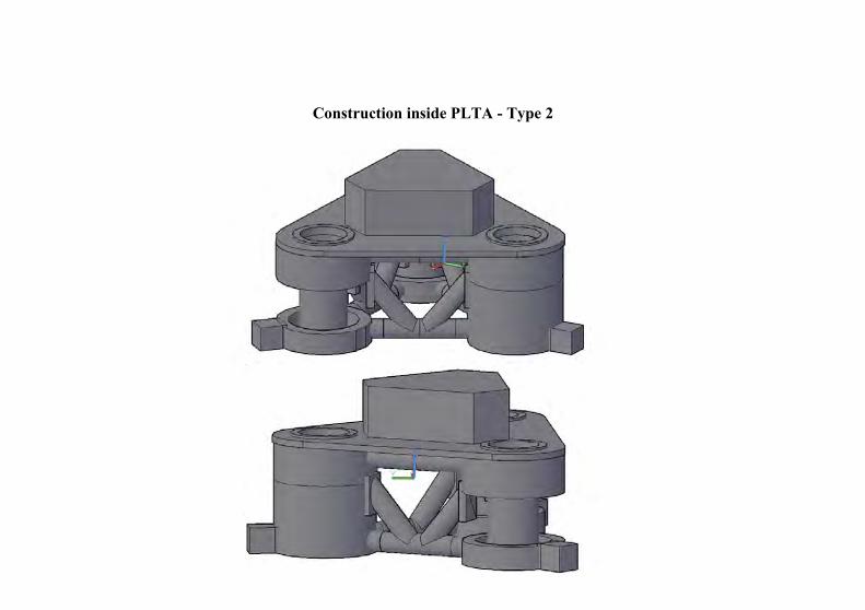
Construction inside PLTA - Type 2
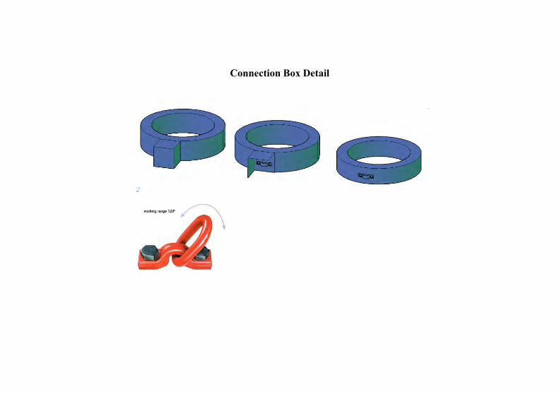
Connection Box Detail
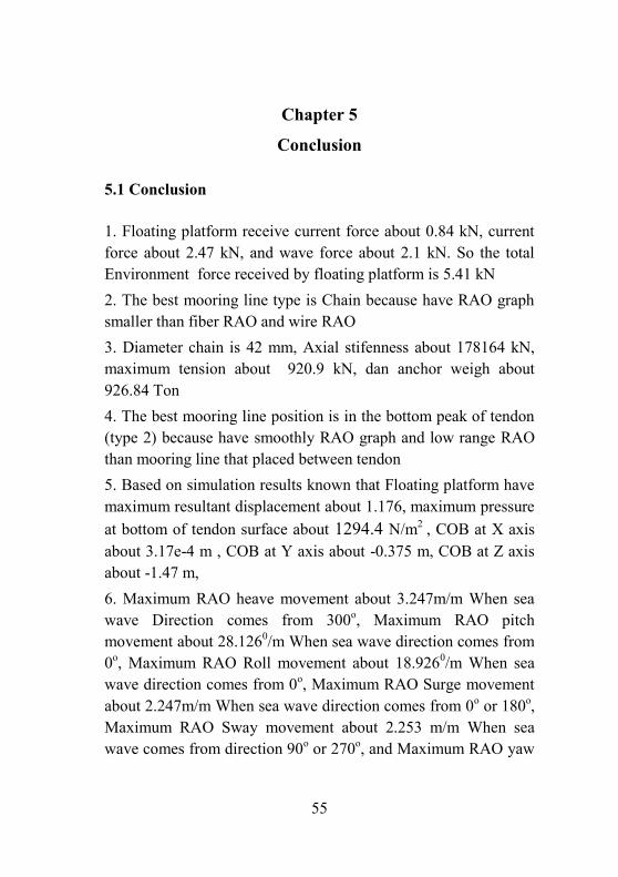
55
Chapter 5
Conclusion
5.1 Conclusion
1. Floating platform receive current force about 0.84 kN, current force about 2.47 kN, and wave force about 2.1 kN. So the total Environment force received by floating platform is 5.41 kN 2. The best mooring line type is Chain because have RAO graph smaller than fiber RAO and wire RAO 3. Diameter chain is 42 mm, Axial stifenness about 178164 kN, maximum tension about 920.9 kN, dan anchor weigh about 926.84 Ton 4. The best mooring line position is in the bottom peak of tendon (type 2) because have smoothly RAO graph and low range RAO than mooring line that placed between tendon 5. Based on simulation results known that Floating platform have maximum resultant displacement about 1.176, maximum pressure at bottom of tendon surface about 1294.4 N/m2 , COB at X axis about 3.17e-4 m , COB at Y axis about -0.375 m, COB at Z axis about -1.47 m, 6. Maximum RAO heave movement about 3.247m/m When sea wave Direction comes from 300o, Maximum RAO pitch movement about 28.1260/m When sea wave direction comes from 0o, Maximum RAO Roll movement about 18.9260/m When sea wave direction comes from 0o, Maximum RAO Surge movement about 2.247m/m When sea wave direction comes from 0o or 180o, Maximum RAO Sway movement about 2.253 m/m When sea wave comes from direction 90o or 270o, and Maximum RAO yaw
56
movement about 2.0250/m When sea wave comes from direction 2400 or 300o
5.2 Suggestion
Calculation will be more accurate if tide force, but tide force can’t be calculated and predicted. To calculate and predicted tide force need a experimentation at location during a year.
57
References Book:
1) Srinivasan, Chandrasekaran. 2015. Dynamic Analysis And
Design Of Offshore Structures
2) J.M.J. Journée , W.W. Massie. 2001.Offshore
Hydromechanics First edition. Delft University of
Technology
3) Anchor Manual 2015 - the guide to anchoring – from
global maritime
4) Use Of Drag Embedment Anchor For Floating Wind
Turbines. Vryhof Anchors BV
5) Budi, Eko Jatmiko.2012. Prilaku operabilitas bangunan
laut di atas gelombang acak. Surabaya: ITS press
6) Indiyono.2010. Hidrodinamika Dasar Bangunan Laut.
Surabaya: ITS Press
7) Soegiono. 2004. Teknologi Produksi dan Perawatan
Bangunan Laut. Surabaya: ITS Press.
8) American Petroleum Institute Recommended Practice 2
SK
9) DNV-OS-E301
10) DNV-OS-E302
11) DNV-OS-E303
12) DNV-OS-E304
13) DNV-OS-C101
58
14) DNV-RP-C205
15) Ansys 2014 Manual Book
Website : 1. http://www.globalsecurity.org/military/systems/ship/platf
orm-tension-leg.html
2. http://www.houston-offshore.com/solutions/tension-leg-
platform/
3. http://www.floatingwindfarm.weebly.com
4. http://Wikipedia.com
5. http://www.wikiwaves.org
6. http://sciencedirect.com
Journal:
(1) Chang Gill kim. Ocean and polar research. Volume 23.
2001. Busan; South Korea
59
Author Biography
The author was born in Yogyakarta, May 17, 1994. The author is the second child of four brothers. The author had education at SDN 1 Cipanas, SMPN 1 Cipanas, SMAN 1 Cianjur, and the last is received in Double degree program of marine engineering German-Indonesian at
Institute Technology Of 10 Nopember, Surabaya. During lecturing process in institute, the author active in Cianjur student associations in Surabaya and is a member of the MMD (manufacture marine design) laboratory. The author is very interested in Ship construction and system process using the software engineering, then attended many seminar and training held marine software company like as bentley. To improve experience in marine industry, author doing on job training in shipyard as 2 times. Author have abilities to using Autocad 2D and 3D, Maxsurf, Skech up, Ansys Aqwa, and Autocad 3D Plant.