Embed Size (px)
Citation preview

i
Bachelor Thesis
Control of Temperature
Using Fuzzy System Technique
Authors : Elif Ceylan Kolbaşı Supervisor:Göran Ewing Examiner: Pieterllerna Cijvat Date:2013-06-07 Course Code: 2ED07E Bachelor Degree,
Institutionen för fysik och elektroteknik

2
ABSTRACT
Fuzzy control is based on fuzzy logic. A logical system that is much closer in spirit to human thinking and natural language than traditional crisp logical systems. The fuzzy logic variables are not described as true or false values. Instead values range in degree between 0-1,true-false or yes-no. Fuzzy logic provides as a means of converting with linguistic control strategy.This strategy rules are based on expert knowledge that is invented by a plant operator or a design egineer. Especially the exposition includes a discussion of fuzzification and defuzzification strategies,the derivation of the database and fuzzy control rules,the definition of fuzzy implication and an analysis of fuzzy reasoning mechanisms. Fuzzy logic is used in machine control widely .Although genetic algoritms and neural networks can perform as well as fuzzy logic in many cases. In the other hand fuzzy logic has advantage that the solution of problem can be formalize terms in that human operators can understand easily so their experience can be used in the design of the controller. Fuzzy controller is generally nonlinear because it doesn’t have a simple equation like the PID ,but also PID control is not convenient in that case of higher-order plants.The fuzzy controllers appear in consumer products.For instance washing mashines,video cameras,underground trains and robots.A fuzzy controller acts or regulates by means of rules in a more or less natural language based on the distinguish feature: fuzzy logic.
ACKNOWLEDGEMENT
I would like to thank my supervisor Professor Göran Ewing for helping the most sincere feelings. Our laboratory working was long and challenging and I also would like to express my gratitude for being patient and helpful about make me able to complete this thesis. His guidance and experience has been a great source of illustrative for me throughout the thesis work.It has been a great occasion working with Linnaeus University for me. Finally I would like to express my special thanks to my parents for there support about my studies
3
CONTENTS
1. Introduction 1.1. Experimental Method...................................................................................1 1.2. Mathematical Modeling................................................................................1 1.3. Heuristics Method.........................................................................................2
2. Theory 2.1. Why use fuzzy logic for control?..................................................................................3 2.2. Fuzzy Systems..............................................................................................................3 2.3. Fuzzy Sets....................................................................................................................4 2.4.Linguistic Variables & Terms........................................................................................4 2.5. Membership Function.................................................................................................5 2.6. Fuzzy Logic..................................................................................................................6 2.6.1 Example..............................................................................................................7 2.7. Fuzzy Control..............................................................................................................8 2.7.1 Fuzzy Control in Detail.......................................................................................9 2.7.2 Fuzzification.....................................................................................................11 2.7.3 Inference..........................................................................................................12 2.7.4 Defuzzification.................................................................................................12 2.7.5 Rule-Based Controllers....................................................................................14 2.7.6 The Mamdani Controller.................................................................................14 3. Methods for Implementation 3.1.1 Siemens Fuzzycontrol++ ......................................................................................15 3.1.1.1 System requirements................................................................................15 3.1.1.2 Hardware requirements............................................................................15 3.1.1.3 Software requirements.............................................................................16 3.1.2. Generating a Fuzzy System..................................................................................16 3.1.3. Configuration of the fuzzy system........................................................................16 3.1.4. Editing the Inputs and Outputs............................................................................18 3.1.5. Membership functions.........................................................................................19 3.1.6. Rule Matrix...........................................................................................................20 3.1.7. Establish the Coneection......................................................................................21 3.2.1. LabView National Instruments.............................................................................21 3.2.2. Inroduction to control and Simulation.................................................................22 4. An Example on a Fuzzy Control 4.1. Acceleration Control on a Vehicle...........................................................................25 4.2. Fuzzification.............................................................................................................25 4.3. Inference..................................................................................................................26 4.4. Defuzzification..........................................................................................................27
4
5. Laboratory Work 5.1 The Process............................................................................................................29 5.2 Output from the Process - input to Fuzzy Control.................................................31 5.3 Output from the Fuzzy Control – Input to the Process..........................................32 5.4 Conversion of configurates and Voltage into Numbers.........................................33 5.5 Define the Output Coils..........................................................................................34 5.6 Fuzzy Set for LOW,MEDIUM and HIGH Temperature.............................................35 5.7 The Output Function..............................................................................................36 5.8 Tests..........................................................................................................37
6. Summation......................................................................................................38
References.......................................................................................................39
1
1. INTRODUCTION
Once fuzzy relations are defined ,it is possible to develop fuzzy relational databases.The first fuzzy relational database,FRDB,appeared in Maria Zemankova’s dissertation.Later some other models arose like the Buckles-petry model the Prade-Testemale Model ,The Umano-Fukami model or the GEFRED model by J.M.Medina ,M.A. Vila et al. İn the context of fuzzy databases some fuzzy querying languages have been defined ,highlighting the SQL by P.Bosc et al. and the FSQL by J.Galindo et al. These languages define some structures in order to include fuzzy aspects in the SQL statements,like fuzzy conditions,fuzzy comparators ,fuzzy constants,fuzzy constraints,fuzzy threshold,linguistic labels and etc [1] . Fuzzy logic is a way to make machines more intelligent enabling them to reason in a fuzzy manner like humans.Fuzzy logic proposed by Lotfy Zadeh in 1965, emerged as a tool to deal with uncertain ,imprecise ,or qualitative decision making problems [2]. Traditional control approach requires modeling of physical reality.Three methods may be used in the despriction of a system [3]:
1.1-Experimental Method:By experimenting and determining how the process reacts to various inputs one can characterize an input-output table .Graphically the method is equivalent to plotting some discrete points of the input-output curve,using the horizontal axis for input and the vertical axis for output .By understanding such input-output reaction ,one can design a controller .The disadvantages are several the process equipment may not be available for experimentation.The procedure would usually be very costly ,and for a large number of input values it is impractical to measure the output and interpolation between measured outputs would be required.One must also be careful to determine the expected ranges of inputs and outputs to make sure that they fall within the range of the measuring intruments available.
1.2-Mathematical Modeling: Control engineering requires an idealized mathematical model if the controlled process,usually in the form of differantial or difference equations.Laplace transforms and z-transforms are often used.In order to make mathematical models simple enough,certain assumotions are made ,one of which is that the process is linear,that is its output is proportional to th input.Linear tecniques are valuable because they provide good insight .Besides,there exist no general theory fort he analytic solution of nonlinear differantial equations and consequently no comprehensive analysis tools for nonlinear dynamic systems.Another assumption is that the process parameters do not change in time despite system component deterioration and environmental changes . The following problems arise in developing a meaningful and realistic mathematical of description of an industrial process:
Poorly understood phenomena Inaccurate values of various parameters Model complexity

2
1.3-Heurictics Method:The heurictic method consists of modeling and understanding in accordance with previous experince ,rules-of-thumb and often used strategies.A heurictic rule is a logical implication of the form :IF<condition>THEN <consequence>or in a typical control situation :IF<condition>THEN<action>.Rules associate conclusions with conditions.Therefore,the heurictic method is actually similar to the experimental method of constructing a table of inputs and corresponding output values where instead of having crisp numeric values of input and output variables,one use fuzzy values:IF input_voltage:large THEN outout_voltage:medium.The advantages of the heurictic method are :
İt is not required the assumption of linearity Heurictic rules can be integrated to the control strategies of human operators.
Fuzzy control strategies come from experience and experiments rather than form mathematical models and linguistic implementations are much faster accomplished.Fuzzy control strategies involve a large number of inputs, most of which are relevant only for some special conditions. Such inputs are activated only when the related condition prevails.In this way little additional computational overhead is required for adding extra rules.As a result, the rule base structure remains understandable ,leading to efficient coding and system documentation.
3
2. THEORY
2.1 WHY USE FUZZY LOGİC FOR CONTROL?
An algorithm that transforms sensor inputs into corresponding control values is called a control strategy. If traditional control methodology cannot be applied, how can one control? Often there is an additional expert knowledge available for example , expert operators who successfully control the desired system. Expert operators know how to to operate a plant. Therefore it is desirable to extract the control rules from the expert and use this knowledge in an automatic control system. The examples shows us that good knowledge of a plant to be controlled is beneficial. To analyse a stability model is even necessary .But more important ,the PID controller design step gives us a tuning Kc,Ti and Td that we could transfer to the fuzzy controller. There the PID controller constitutes a reference for assessment of the performance of the fuzzy controller. It is quite difficult to design a fuzzy controller because it is in nonlinear and nonlinear systems are more or less unpredictable.Instead of propose to stay as long as possible in the linear domain ,reflected in the proposed deign procedure.The idea is to start from PID control design a linear fuzzy controller that is equivalent to a pre-designed PID controller.At this point all the results from linear control theory can be applied including tuning methods and stability calculations.In the next phase the fuzzy controller is made nonlinear. The design procedure has limited scope in the sense that it requires a PID controller to be built to control the plant.As a compensation for the limited scope the design procedure provides reliability :it guarantees that the fuzzy controller performs at least as well as its pre-designed PID controller.There is a possibility but no guarantee that it will perform better[4].
2.2 FUZZY SYSTEMS
System of variable which is related using fuzzy logic so as to create a fuzzy system.Fuzzy controller uses defined rules to control a fuzzy system based on the of known values of input variables. The first step in designing a fuzzy system with the fuzzy system designer is to constitute the input and output linguistic variables for the system.Traditional Boolean logic consists of two value because a member either belongs to a set or doesn’t .Values of one and zero symbolize the membership to the set with one representing accurate membership and zero can be defined as no membership.Fuzzy logic bring into use for partial membership or a degree of membership that may be any value along the operation of zero to one.
4
2.3 FUZZY SETS
Fuzzy set theory is an extension of classical set theory .Under this aspect the term of the membership function is introduced. The operations sets are introduced and explained and illustrated using membership functions. Starting with elementary operators for fuzzy sets more complicated operators for modeling of rule bases and reasoning processes are introduced . Fuzzy logic is based on fuzzy sets and with fuzzy logic a computer can process words from natural language such as “small”,”large” and “approximately equal ”.A fuzzy set is represented by a membership function defined on the universe of discourse.The universe of discourse is the space where the fuzzy variables are defined. The membership function gives the grade or degree of membership within the set of any element of the universe of discourse.The membership function maps the elements of the universe onto numerical values in the interval [0,1] .A membership function value of zero implies that the corresponding element is definitely not an element of the fuzzy set while a value of unity means that the element fully belongs to the set[5].
2.4 LİNGUİSTİC VARİABLES & TERMS
Linguistic variables symbolize the input variables and output variables of the system whatever we want to control .If we would like to give an example it can be a heater. We may have two linguistic variables ;current temperature and desired temperature and the one output linguistic variable heater setting. Each linguistic variable has a range of expected values.For instance we assume that the range of current could be the interval 0-150 degrees.The range of desired temperature might be 40-80 degrees. Memebership functions are used as numerical functions instead of to linguistic terms. A membership function represents the degree of membership of linguistic variables within their linguistic terms.There are some relationships between input and output.These variables can be described with linguiatic terms.For example;
IF current temperature is cold AND desired temperature is moderate,THEN heater setting is low
The clauses “current temperature is cold” and desired temperature is moderate” are the antecedents of this rule The AND connective specifies how the fuzzy logic controller relates the two antecedents to determine the truth value for the aggregated rule antecedent.The clause “heater setting is low” is the consequent of this rule.A rule base is the set of rules for a fuzzy system.The rule base is equivalent to the control strategy of the controller [6].
5
2.5 MEMBERSHİP FUNCTİON
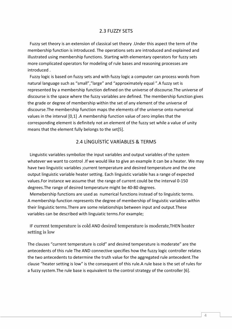
The membership of the elements are defined in the membership function µ(x).The membership of the elements x of the base is constituted in the fuzzy set A. For µ(x) a widely class of functions can be taken.Reasonable functions are usually piece by piece linear functions,such as triangular or trapezoidal functions.
Figure-1 : Membership grades of 푥 in the sets A and B (www.mstarlabs.com)
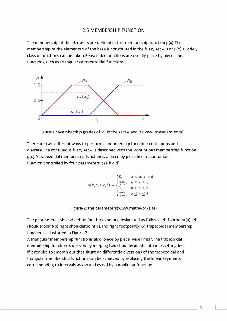
There are two different ways to perform a membership function: continuous and discrete.The contunious fuzzy set A is described with the continuous membership function µ(x).A trapezoidal membership function is a piece by piece linear ,contunious function,controlled by four parameters ; {a,b,c,d}
Figure-2: the parameters(www.mathworks.se)
The parameters a≤b≤c≤d define four breakpoints,designated as follows:left footpoint(a),left shoulderpoint(b),right shoulderpoint(c),and right footpoint(d).A trapezoidal membership function is illustrated in Figure-2. A triangular membership functionis also piece by piece wise linear.The trapezoidal membership function is derived by merging two shoulderpoints into one ,setting b=c. If it require to smooth out that situation differentiale versions of the trapezoidal and triangular membership functions can be achieved by replacing the linear segments corresponding to intervals a≤x≤b and c≤x≤d by a nonlinear function.
6
According to Zadeh a fuzzy set persuade a possibility distribution on the universe that indicate how one can interpret the membership values as possibilities.How are then possibilities related to probabilities ? Primarily probabilities need to add up to one or the area under a density curve should be one.Membership require to add up to anything (discrete case) or the area under the membership function need to be anything(continuous case).In the second place a probability distribution concerns the feasibility for the eventuating of an event based on observations whereas a possibility distribution(membership function )is subjective.The word ‘probably’ is synonymous with ‘presumably’ , ’assumably’ , ’doubtless’ , ’likely’ ,or ‘presumptively’.The word ‘possible’is synonymous with ‘doable’ , ‘feasible’ , ‘practicable’ , ‘viable’ , or ‘workable’.Their relationship is represented in the sentence perfectly. ‘What is probable is always possible,but not contrary.’
2.6 FUZZY LOGİC
Every element is member of or is not a member of a set by classic set theory.For this reason membership is defined with just two values(yer/no,1/0 , true/false).Sets with such binary membership functions are called non-fuzzy sets.Fuzzy logic is developed and then expands the membership function to allow intermediate values and hence it could be obtained better simulation for describing to human thinking. However not using a mathematical model of the process is also a source of amphiboly.For instance the many degrees of freedom in designing fuzzy systems can be a special disadvantage.
The study of logic started as a study of language in claim and persuasion and it could be used to judge the accuracy of chain of reasoning in a mathematical evidence for instance.
The following overwiew provides a comparison [7]:
Simple implementation of verbally expressed rules (if..,Then..) on a computer to solve a problem.
The behavior of the fuzzy system is understandable to human beings. Avoids the costly development of a mathematical description when compared
with conventional methods. Possible to use for processing complicated and involved processes. Task definitions with not enough knowledge of the system and little or very
imprecise knowledge of the system behavior result in bad probably unusable fuzzy solutions.
Generally no adaptability and find out capability if the system behavior changes. Design of a system need experience owing to many degrees of freedom.
7
Fundamentally the aim of the theory is to decrease principles of reasoning to a code.It is quite similar to programming language.Logic builds on truth values(constants),connectives(operators)and rules of inference(programming constructs).
Fuzzy control is based on fuzzy logic that is in turn based on fuzzy set theory.If the idea of a fuzzy is to explain simply:an object is allowed to have gradual membership of a set.The idea of the fuzzy set dominates all derived mathematical aspects of the set theory.In fuzzy logic an argument is enabled to be more or less true .A truth value in fuzzy logic is a real number in the interval[0,1] but the classical logic is a set of two truth values {0,1}.
Classical logic might be fuzzified in many ways.the Main problem is also to find a convenient characterization ‘inference’.Fuzzy reasoning is based on the modus ponens rule of implication that rests on the characterization of inference.Fuzzy system is a trade –off between mathematical precision and enginnering requirements. If a backward is described step by step that is offered;
1. First of all decide the laws that are needed 2. Define ‘and’ ,’or’ ,’not’ , ‘inference’ and ‘equivalence’ 3. Check by means of their truth –tables whether the laws in step 1 hold ;and 4. If not go to 2.
Fuzzy logic has seen many applications one of them being fuzzy control.There is a lot of things to be said about fuzzy logic and fuzzy control applies just a subset of the depot of operations and explanation. Fuzzy logic is appropriate for information processing.İnformation processing is usually necessary when specified by linguistic expressed algorithms in the form of “IF-THEN” rules.For instance manufacturing processes can be observed by operators.They may control the actions on the basis of their experience with simple if-then rules.Using it this way is useful for success with good results. Fuzzy logic is not delimited with close-loop and open-loop for applications.Such applications are also used for information processing in measured output value,operations management and planning.Fuzzy logic assist it probable to transfer the from experience to computer programming.
2.6.1 Example:
The problem in applying that the take the action fuzzy operator might not be known.Therefore fuzzy logic often uses IF-THEN rules.The rules or constructs which are response for instance fuzzy associative matrices. Rules are usually denoted in the following form:
8
IF variable is property THEN action
A simple temperature regulator that uses a fan can seems like these conditions:
There is no “ELSE” .All of the rules are utilized .The temperature might be “cold “ and “ normal” at the same time to different degrees. The AND ,OR and NOT operators can be defined with Boolean logic that is existed in fuzzy logic.That is usually identified as the min, max and complement when they are identified ith this way .They are called the “ Zadeh operators” .If illustrate the fuzzy variables x and y;
There are also other operators more linguistic in nature ,it is called hedges which could be applied.These are usually adverbs for example “very” or “ a little bit “that modify the meaning of a set using a mathematical formula.
2.7 FUZZY CONTROL
Traditional control systems are on the basis of mathematical model in that the control system is defined using one or more differential equations which describe the system response to its inputs. Such systems are often execute as PID controllers (proportional-integral-derivative controllers).These products of decades are developed and they are pretty effective. If PID control system is developed accomplishedly then Why would we need to use fuzzy control? It has some reason about this usage. There are some advantages however. In many cases the mathematical model of the control process might not exist or may be quiet expensive if we think in terms of computers processing. However fuzzy logic is well-developed to low cost practice based on cheap sensor ,low resolution analog to digital converters and 4-bit or 8-bit one chip microcontroller chips.such systems upgraded easily by adding new rules to improve performance or add new fetures. In many cases fuzzy control can be used to improve existing traditional controller systems by adding an extra layer of intelligence to the current control method [8]. We can use fuzzy controllers for control fuzzy system.Most traditional control algorithms need a mathematical model of the system whatever we want and there is also what many physical systems are difficult or impossible to model mathematically.Furthermore many
IF temperature is very cold THEN stop fan IF temperature is cold THEN turn down fan IF temperature is normal THEN maintain level IF temperature is hot THEN speed up fan
NOT X=(1-truth(X)) X and Y =min(truth(X),truth(Y)) X or Y =max(truth(X) ,truth(y))
9
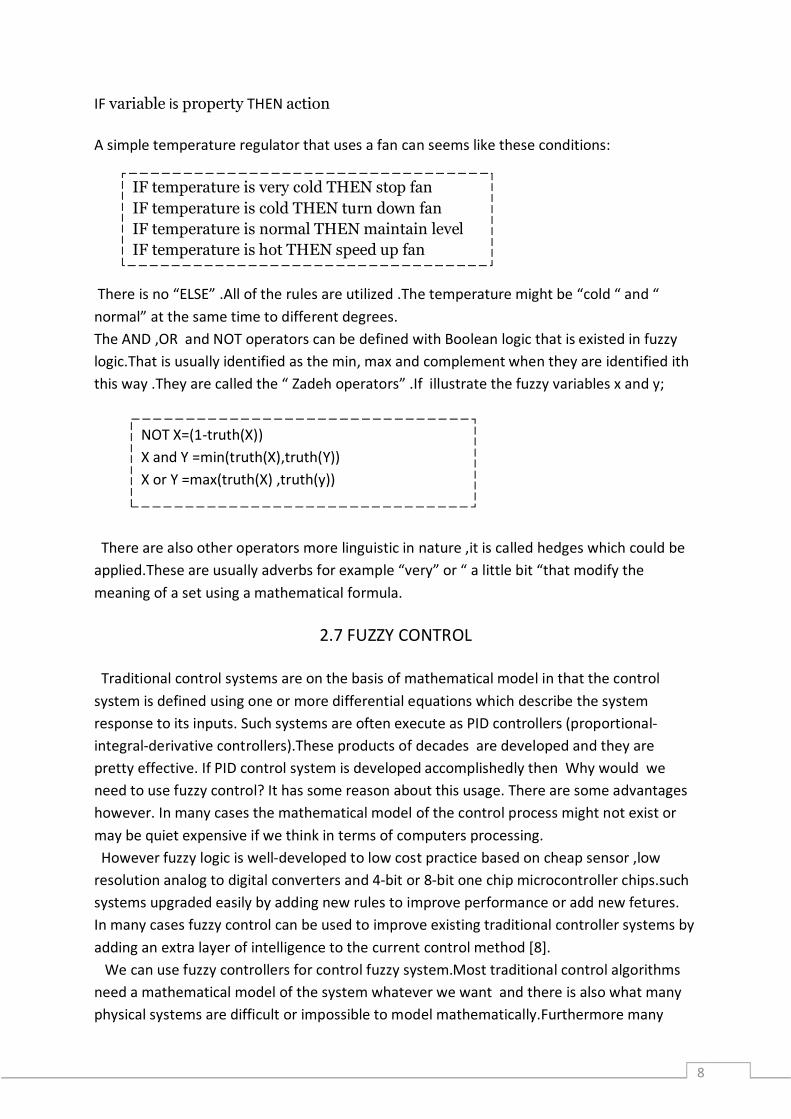
processes are either nonlinear or quiet complex for us to control with traditional strategies.If we illustrate a control strategy qualitatively we can use fuzzy logic for create a fuzzy controller which assimilates to a heurictic rule-of-thumb strategy.
Figure-3: Process of a fuzzy controller(Siemens user`s manual)
2.7.1 FUZZY CONTROL İN DETAİL
Fuzzy controller have very simple structure. The structure is made up of an input stage,a processing stage and output stage. The input stage maps sensors or other inputs for instance switches ,thumb wheels etc. to the appropriate membership and truth values. The processing begin each suitable rule and achieve a result for each. Then combines the results of the rules. As a result of is the output stage converts the combined result back into a specific control output value. The most common shape of membership function is triangular despite the fact that trapezoidal and bell curves are used. The shape is usually less important than the number of curves and their placement. From three to seven curves are often suitable to cover the needed interval of an input value or the “universe of discourse” in fuzzy technical language. Generally membership functions define several various conditions. Such as normal distribution,sigmoid function,trapezoidal function. Triangular and trapezoidal are frequently used . They can be defined with 3 or 4 corners.
(Siemens user`s manual)
The advantage of modeling with fuzzy logic is prepared to take action by operators.If the pressure display reaches 115 bar the pressure can be considered as %30 .A binary control with athreshold value contact at 120 bar would not be able to apply sufficient operation and would be able to understand the situation all of a sudden when the pressure value left the non fuzzy set. On the other hand operator can be able to
10
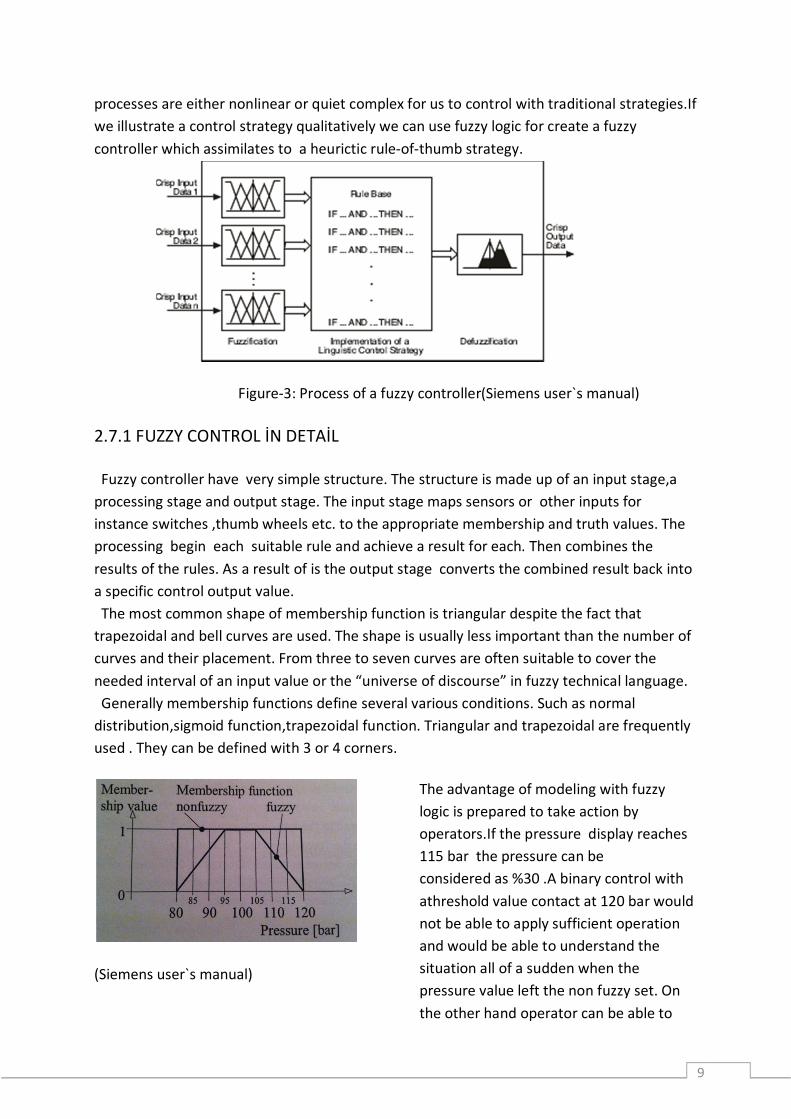
recognize critical values.If the operator run into a problem the operator can respond to time taking any necessary counter-measures. To resemble this behavior it is needed to use a fuzzy system instead of a binary control.
Figure-4: Direct control
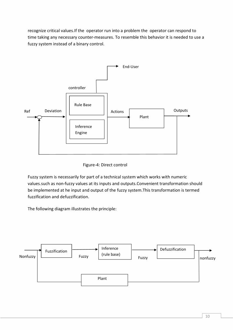
Fuzzy system is necessarily for part of a technical system which works with numeric values.such as non-fuzzy values at its inputs and outputs.Convenient transformation should be implemented at he input and output of the fuzzy system.This transformation is termed fuzzification and defuzzification.
The following diagram illustrates the principle:
Nonfuzzy Fuzzification
Fuzzy
Inference (rule base)
Fuzzy
Defuzzification
nonfuzzy
Ref DeviationPlant
Actions Outputs
controller
Inference Engine
Rule Base
End-User
Plant
11
2.7.2 FUZZİFİCATİON
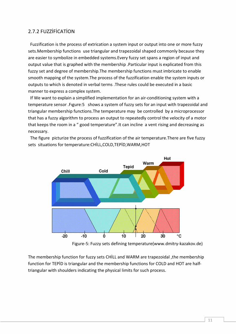
Fuzzification is the process of extrication a system input or output into one or more fuzzy sets.Membership functions use triangular and trapezoidal shaped commonly because they are easier to symbolize in embedded systems.Every fuzzy set spans a region of input and output value that is graphed with the membership .Particular input is explicated from this fuzzy set and degree of membership.The membership functions must imbricate to enable smooth mapping of the system.The process of the fuzzification enable the system inputs or outputs to which is denoted in verbal terms .These rules could be executed in a basic manner to express a complex system. If We want to explain a simplified implementation for an air-conditioning system with a temperature sensor .Fıgure:5 shows a system of fuzzy sets for an input with trapezoidal and triangular membership functions.The temperature may be controlled by a microprocessor that has a fuzzy algorithm to process an output to repeatedly control the velocity of a motor that keeps the room in a “ good temperature”.It can incline a vent rising and decreasing as necessary. The figure picturize the process of fuzzification of the air temperature.There are five fuzzy sets situations for temperature:CHİLL,COLD,TEPİD,WARM,HOT
Figure-5: Fuzzy sets defining temperature(www.dmitry-kazakov.de) The membership function for fuzzy sets CHİLL and WARM are trapezoidal ,the membership function for TEPİD is triangular and the membership functions for COLD and HOT are half-triangular with shoulders indicating the physical limits for such process.
12
2.7.3 INFERENCE For each rule of base the degree of completion of the THEN part is structured to the degree of completion of the IF part by a certain method. This process is called inference.The degree of completion of the THEN part is corresponding to the degree of completion of the rule that is called the rule intensity.İndividually rule assessment put together result in one membership function for the output signal that is titled composition.Eventually membership function describes a “fuzzy control command” that could.When the IF part include a combined situations “IF…AND…” …(THEN). The fuzzy logic AND operation is applied first and degree of completion is used in full rule evaluation.generally all these statements are titled an aggregation. 2.7.4 DEFUZZİFİCATİON
After fuzzy consideration we have a verbal output variable that is required to be translated into a crisp value. The objective is to derive a single crisp numeric value that the best reflects the inferred fuzzy values of the verbal output variable.Defuzzification is reversed transformation that maps the output from the fuzzy domain back into the crisp domain.Some defuzzification methods are disposed to produce an integral output allowance all the elements of the resulting fuzzy set with the instead of weights.Other methods provide account just elements instead of to the max. points of the resulting membership functions.The following defuzzification methods are of practical efficiency [5]: Center-of-Area : the C-o-A method is often referred to as the center-of-gravitty method because it computes the centrod of the composite area representing the output fuzzy term. Center-of-Maximum : In the C-o-M method only the peaks of the membership functions are used.The defuzzified crisp compromise value is determined by finding the place where the weights are balanced.Hence the areas of the membership functions play no role and only the maxima are used.The crisp output is computed as a weighted mean of the term membership maxima,weighted by the implementation results. Mean -of-Maximum : the M-o-M is used in some cases where C-o-M approach does not work. This happens whenever the maxima of the membership functions are not unique and questions is as to which one of the equal choices one should take
13
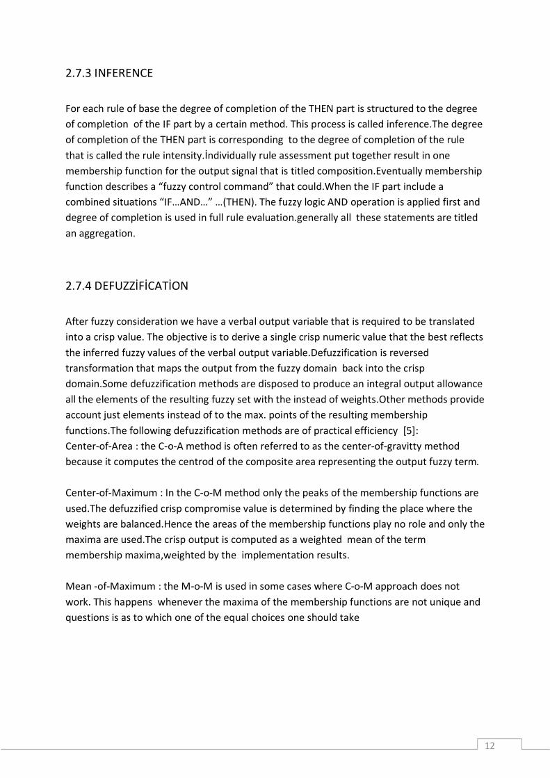
Figure-6 :The diagram above proves max-min implementations and centroid defuzzification for a system with input variables x,y,z and an output variable n. Mu:is standart fuzzy logic idioms for truth value.( en.wikipedia.org) Fuzzy control system design is based on empirical methods.This methods show an approach to trial and error.The general process is as follows:
Document the systems executional recognition and inputs,outputs Document the fuzzy sets for inputs Document for rule set Determine the defuzzification methodology Review test correspond with confirm system specify details as needed Complete document and put up for sale
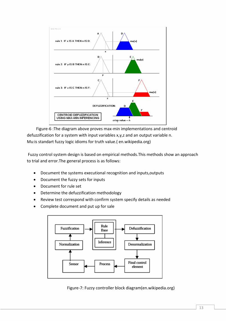
Figure-7: Fuzzy controller block diagram(en.wikipedia.org)
14
2.7.5 RULE –BASED CONTROLLERS
Three separate variants of controller have transformed historically: The Mamdani the FLS and the Sugeno controllers.They use the same general implementation scheme but the most important difference is complied with the activation method and ultimate membership functions. A SISO rule base will pinpoint the essential deffrences;
The input is an error proportional to the excursion from the set point .The control action has the same sign as error verbally.Hence the rule base represent a fuzzy comparatively between error and control and the controller Is a fuzzy verison of a proportional controller.
2.7.6 THE MAMDANİ CONTROLLER
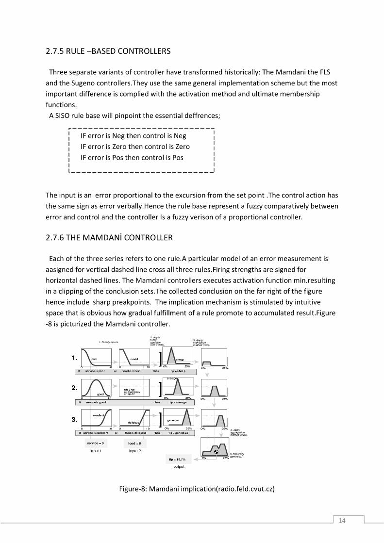
Each of the three series refers to one rule.A particular model of an error measurement is aasigned for vertical dashed line cross all three rules.Firing strengths are signed for horizontal dashed lines. The Mamdani controllers executes activation function min.resulting in a clipping of the conclusion sets.The collected conclusion on the far right of the figure hence include sharp preakpoints. The implication mechanism is stimulated by intuitive space that is obvious how gradual fulfillment of a rule promote to accumulated result.Figure -8 is picturized the Mamdani controller.
Figure-8: Mamdani implication(radio.feld.cvut.cz)
IF error is Neg then control is Neg IF error is Zero then control is Zero IF error is Pos then control is Pos

15
3. METHODS FOR IMPLEMENTATION 3.1.1 SİEMENS FUZZYCONTROL++
Using the fuzzy control++ configuration tool consists of two main operations:
3.1.1.1 SYSTEM REQUIREMENTS
The fuzzycontrol++ configuration tool include a windows program(configuration tool) and different runtime modules(function data blocks for SIMATIC S7-300,SIMATIC S7-400 and runtime library for SIMATIC WinCC).The confıguration tool is used to configure and create fuzzy systems.The runtime modules may then apply these created systems during the runtime operation on the corresponding target platform.
There are three runtime modules for: SIMATIC S7 SIMATIC CFC(OPTİONAL) SIMATIC WinCC
3.1.1.2HARDWARE REQUIREMENTS
Configuration tool : PC and PG with 80486 processor(or higher), At least 16MB memory (RAM) At least 16MB free hard disk space
S7 function blocks: S7-300 CPU 314 or better ,S7-400 MPI interface for computer The PB(profıbus)TCP/IP and IE bus systems are held up
CFC function block :S7-400 MPI interface fot he computer The PB ,TCP/IP and IE(industrial Ethernet) bus systems are held up [7].
- A fuzzy system meeting the disclose necessity must be constituted as a system of basis.In the sequel changes to the fuzzy system are still possible.
- It is necessary to establish a connection with the targetsystem and make the fuzzy system to know inputs and outputs.

16
3.1.1.3 SOFTWARE REQUIREMENTS
Configuration tool: Windows 200 ,Windows XP S7 and CFC function blocks:SIMATIC SOFTNET S7/PB Optionally SIMATIC SOFTNET S7 IE with TCP/IP ,IE connection [7].
3.1.2 GENERATİNG A FUZZY SYSTEM
The starting point in processing is the problem to be solved with the targetsystem . A project is a fuzzy system determined by the choice of targetsystem its inputs and outputs and its rule basic . To edit a project we can either open an existing project or create a new project.For an existing project we can load its file with the extension *.flp(fuzzy programming language)or *.fcl(fuzzy control language) with open in the file menu.A new project is entitled the as project name “NEW” automatically .First when we save the project we can decide the name to it . There is a very simple example in which a control must arrange a valve depending on the temperature and pressure.This control is to be executed in a fuzzy system and program for this aim is to be created and transferred in the control unit that is the targetsystem.With the fuzzycontrol++ tool we could generate the needed system. This guide explain an introduction to editing a project.We can study a typical project if we fulfill the steps (indented text marked as example) with the fuzzycontrol++ tool on the PC.
3.1.3 CONFIGURATION OF THE FUZZY SYSTEM
Configuration of the fuzzy system consist of defining the target system and the number of inputs and output.Besides a standardization should be prepared by the program by specifying min.and.max. values for the inputs and outputs.The target system can be shown or changed at a later time. Defining the number of inputs and outputs as well as the targetsystem; After we opened the fuzzycontrol++ a basic window with the title”fuzzycontrol++” is displayed.This is the working window of that program.The toolbar and status bar are displayed in all the windows and serves as an aid we are operating the program.
17
( (Siemens S7) Run the new command in the file menu displayed in the window indicated above. First a dialog box with the same project in the title bar appears then we can define the external structure.
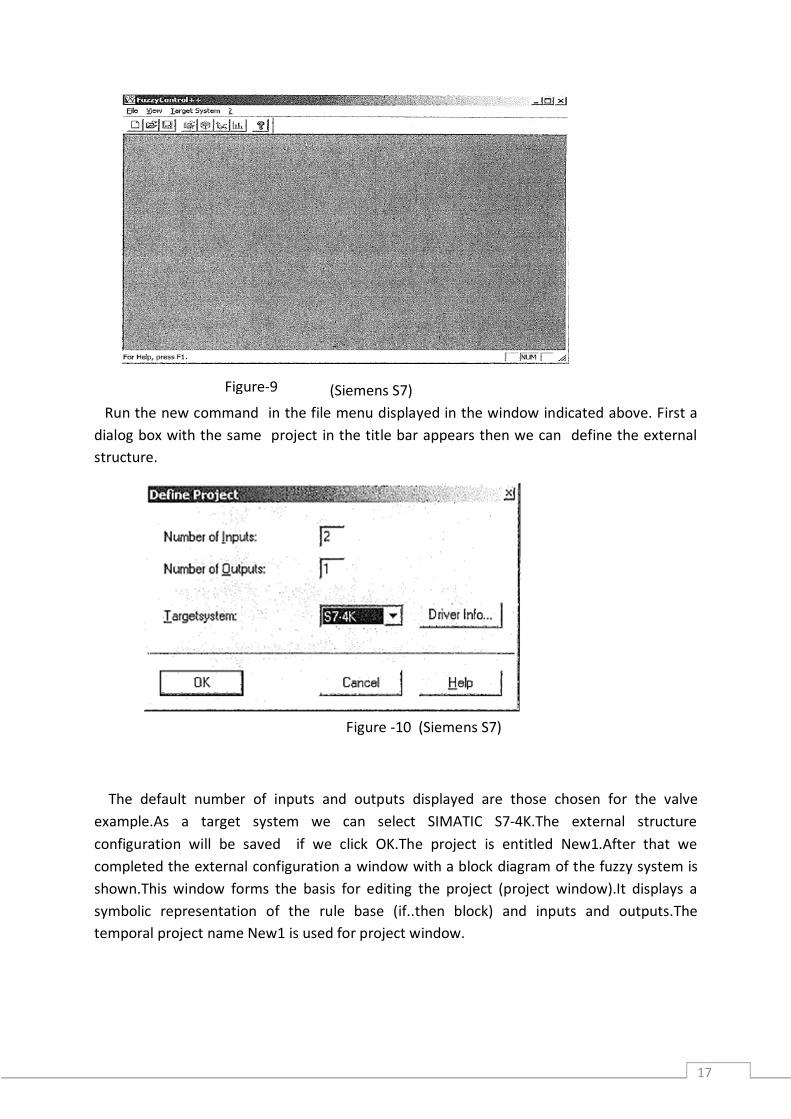
Figure -10 (Siemens S7)
The default number of inputs and outputs displayed are those chosen for the valve example.As a target system we can select SIMATIC S7-4K.The external structure configuration will be saved if we click OK.The project is entitled New1.After that we completed the external configuration a window with a block diagram of the fuzzy system is shown.This window forms the basis for editing the project (project window).It displays a symbolic representation of the rule base (if..then block) and inputs and outputs.The temporal project name New1 is used for project window.
Figure-9
18
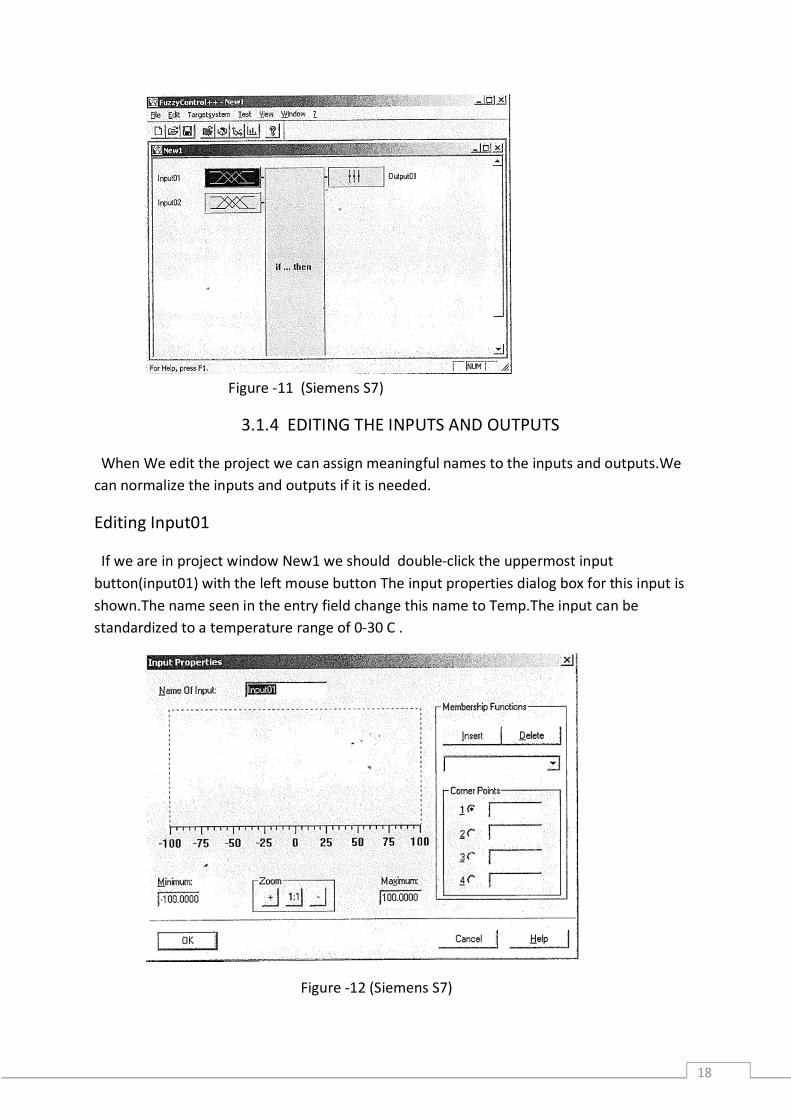
Figure -11 (Siemens S7)
3.1.4 EDITING THE INPUTS AND OUTPUTS
When We edit the project we can assign meaningful names to the inputs and outputs.We can normalize the inputs and outputs if it is needed.
Editing Input01
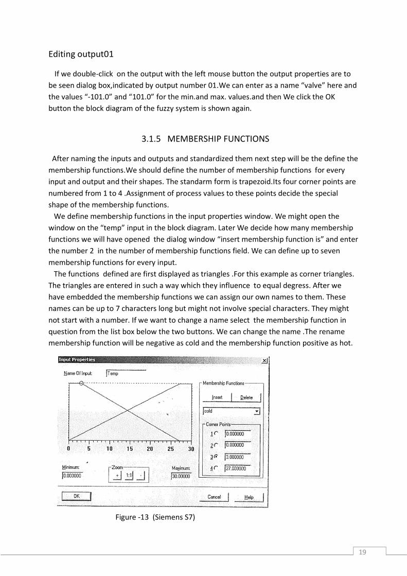
If we are in project window New1 we should double-click the uppermost input button(input01) with the left mouse button The input properties dialog box for this input is shown.The name seen in the entry field change this name to Temp.The input can be standardized to a temperature range of 0-30 C .
Figure -12 (Siemens S7)
19
Editing output01
If we double-click on the output with the left mouse button the output properties are to be seen dialog box,indicated by output number 01.We can enter as a name “valve” here and the values “-101.0” and “101.0” for the min.and max. values.and then We click the OK button the block diagram of the fuzzy system is shown again.
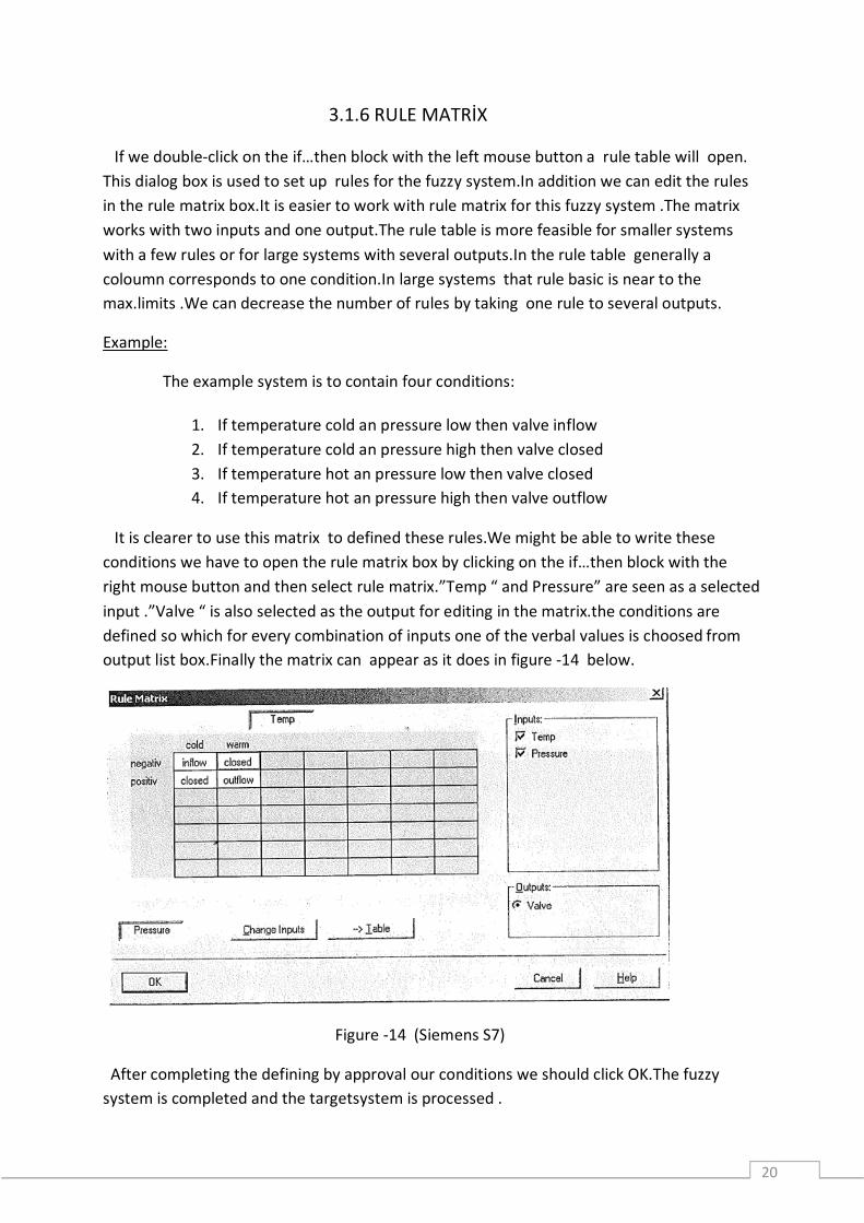
3.1.5 MEMBERSHIP FUNCTIONS
After naming the inputs and outputs and standardized them next step will be the define the membership functions.We should define the number of membership functions for every input and output and their shapes. The standarm form is trapezoid.Its four corner points are numbered from 1 to 4 .Assignment of process values to these points decide the special shape of the membership functions. We define membership functions in the input properties window. We might open the window on the “temp” input in the block diagram. Later We decide how many membership functions we will have opened the dialog window “insert membership function is” and enter the number 2 in the number of membership functions field. We can define up to seven membership functions for every input. The functions defined are first displayed as triangles .For this example as corner triangles. The triangles are entered in such a way which they influence to equal degress. After we have embedded the membership functions we can assign our own names to them. These names can be up to 7 characters long but might not involve special characters. They might not start with a number. If we want to change a name select the membership function in question from the list box below the two buttons. We can change the name .The rename membership function will be negative as cold and the membership function positive as hot.
Figure -13 (Siemens S7)
20
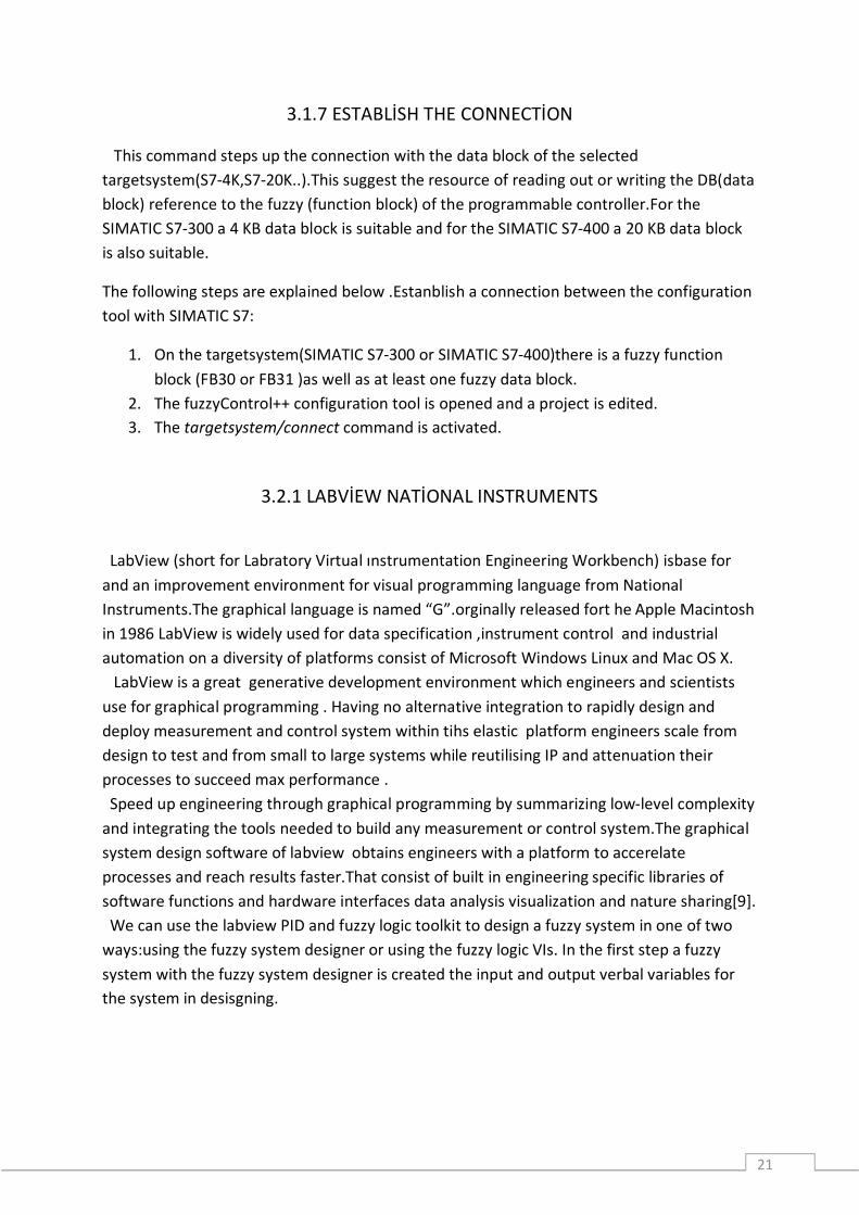
3.1.6 RULE MATRİX
If we double-click on the if…then block with the left mouse button a rule table will open. This dialog box is used to set up rules for the fuzzy system.In addition we can edit the rules in the rule matrix box.It is easier to work with rule matrix for this fuzzy system .The matrix works with two inputs and one output.The rule table is more feasible for smaller systems with a few rules or for large systems with several outputs.In the rule table generally a coloumn corresponds to one condition.In large systems that rule basic is near to the max.limits .We can decrease the number of rules by taking one rule to several outputs.
Example:
The example system is to contain four conditions:
It is clearer to use this matrix to defined these rules.We might be able to write these conditions we have to open the rule matrix box by clicking on the if…then block with the right mouse button and then select rule matrix.”Temp “ and Pressure” are seen as a selected input .”Valve “ is also selected as the output for editing in the matrix.the conditions are defined so which for every combination of inputs one of the verbal values is choosed from output list box.Finally the matrix can appear as it does in figure -14 below.
Figure -14 (Siemens S7)
After completing the defining by approval our conditions we should click OK.The fuzzy system is completed and the targetsystem is processed .
1. If temperature cold an pressure low then valve inflow 2. If temperature cold an pressure high then valve closed 3. If temperature hot an pressure low then valve closed 4. If temperature hot an pressure high then valve outflow
21
3.1.7 ESTABLİSH THE CONNECTİON
This command steps up the connection with the data block of the selected targetsystem(S7-4K,S7-20K..).This suggest the resource of reading out or writing the DB(data block) reference to the fuzzy (function block) of the programmable controller.For the SIMATIC S7-300 a 4 KB data block is suitable and for the SIMATIC S7-400 a 20 KB data block is also suitable.
The following steps are explained below .Estanblish a connection between the configuration tool with SIMATIC S7:
1. On the targetsystem(SIMATIC S7-300 or SIMATIC S7-400)there is a fuzzy function block (FB30 or FB31 )as well as at least one fuzzy data block.
2. The fuzzyControl++ configuration tool is opened and a project is edited. 3. The targetsystem/connect command is activated.
3.2.1 LABVİEW NATİONAL INSTRUMENTS
LabView (short for Labratory Virtual ınstrumentation Engineering Workbench) isbase for and an improvement environment for visual programming language from National Instruments.The graphical language is named “G”.orginally released fort he Apple Macintosh in 1986 LabView is widely used for data specification ,instrument control and industrial automation on a diversity of platforms consist of Microsoft Windows Linux and Mac OS X. LabView is a great generative development environment which engineers and scientists use for graphical programming . Having no alternative integration to rapidly design and deploy measurement and control system within tihs elastic platform engineers scale from design to test and from small to large systems while reutilising IP and attenuation their processes to succeed max performance . Speed up engineering through graphical programming by summarizing low-level complexity and integrating the tools needed to build any measurement or control system.The graphical system design software of labview obtains engineers with a platform to accerelate processes and reach results faster.That consist of built in engineering specific libraries of software functions and hardware interfaces data analysis visualization and nature sharing[9]. We can use the labview PID and fuzzy logic toolkit to design a fuzzy system in one of two ways:using the fuzzy system designer or using the fuzzy logic VIs. In the first step a fuzzy system with the fuzzy system designer is created the input and output verbal variables for the system in desisgning.
22
3.2.2 INTRODUCTION TO CONTROL AND SIMULATION
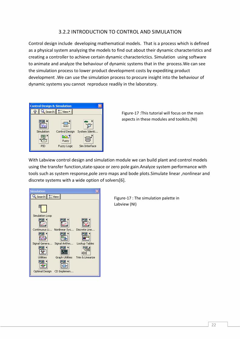
Control design include developing mathematical models. That is a process which is defined as a physical system analyzing the models to find out about their dynamic characteristics and creating a controller to achieve certain dynamic characterictics. Simulation using software to animate and analyze the behaviour of dynamic systems that in the process.We can see the simulation process to lower product development costs by expediting product development .We can use the simulation process to procure insight into the behaviour of dynamic systems you cannot reproduce readily in the laboratory.
With Labview control design and simulation module we can build plant and control models using the transfer function,state-space or zero pole gain.Analyze system performance with tools such as system response,pole zero maps and bode plots.Simulate linear ,nonlinear and discrete systems with a wide option of solvers[6].
Figure-17 :This tutorial will focus on the main aspects in these modules and toolkits.(NI)
Figure-17 : The simulation palette in Labview (NI)
23
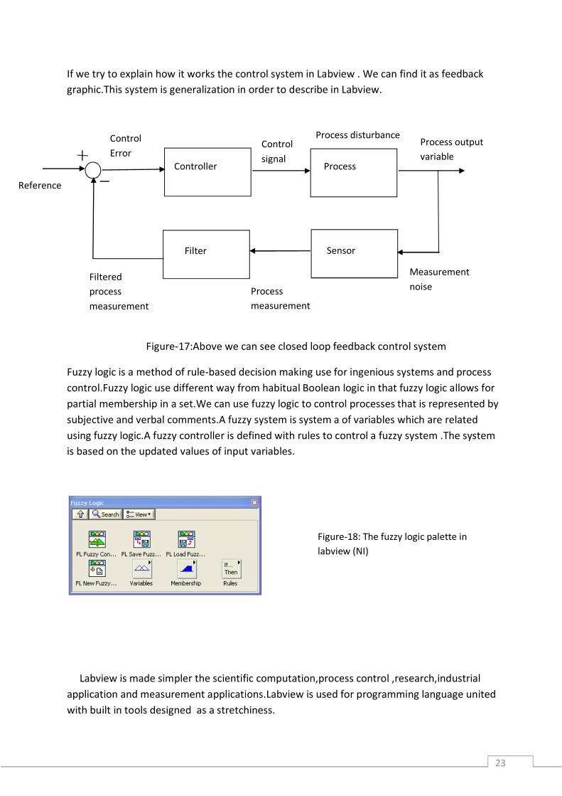
If we try to explain how it works the control system in Labview . We can find it as feedback graphic.This system is generalization in order to describe in Labview.
Figure-17:Above we can see closed loop feedback control system
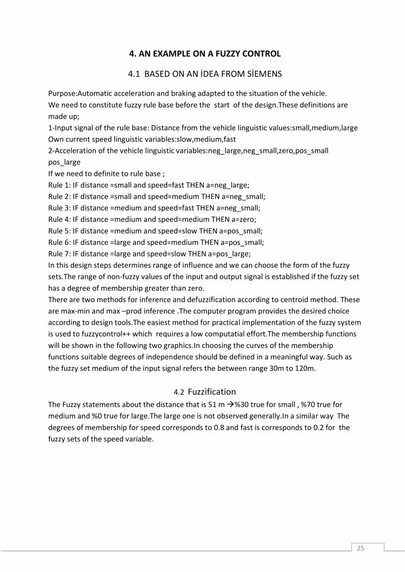
Fuzzy logic is a method of rule-based decision making use for ingenious systems and process control.Fuzzy logic use different way from habitual Boolean logic in that fuzzy logic allows for partial membership in a set.We can use fuzzy logic to control processes that is represented by subjective and verbal comments.A fuzzy system is system a of variables which are related using fuzzy logic.A fuzzy controller is defined with rules to control a fuzzy system .The system is based on the updated values of input variables.
Labview is made simpler the scientific computation,process control ,research,industrial application and measurement applications.Labview is used for programming language united with built in tools designed as a stretchiness.
Controller Process
Filter
Control Error
Sensor
Process output variable
Process measurement
Filtered process measurement
Reference
Process disturbance
Measurement noise
Control signal
Figure-18: The fuzzy logic palette in labview (NI)

24
By using the integrated labview setting to interface with real word signals analyze data for significiant information and share response.For this reason Labview will improve the control system day by day. Fuzzy logic is added for modern control. Advantages in fuzzy control by labview that is more robust control method than usual classic control to conversion of system parameter. There are many stage in labview for completing the fuzzy system.
Creating linguistic variables Creating a rule base Specifying a deffuzzification method Testing the fuzzy system Controlling the fuzzy system
25
4. AN EXAMPLE ON A FUZZY CONTROL
4.1 BASED ON AN İDEA FROM SİEMENS
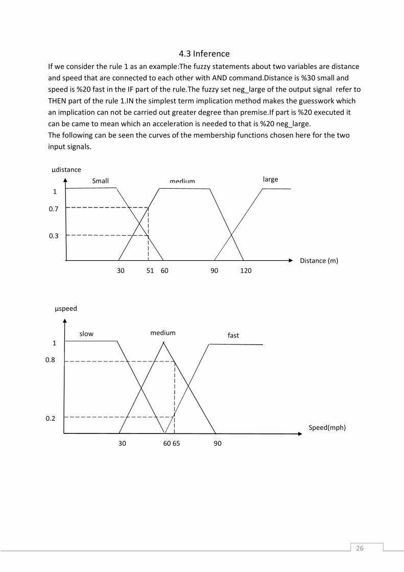
Purpose:Automatic acceleration and braking adapted to the situation of the vehicle. We need to constitute fuzzy rule base before the start of the design.These definitions are made up; 1-Input signal of the rule base: Distance from the vehicle linguistic values:small,medium,large Own current speed linguistic variables:slow,medium,fast 2-Acceleration of the vehicle linguistic variables:neg_large,neg_small,zero,pos_small pos_large If we need to definite to rule base ; Rule 1: IF distance =small and speed=fast THEN a=neg_large; Rule 2: IF distance =small and speed=medium THEN a=neg_small; Rule 3: IF distance =medium and speed=fast THEN a=neg_small; Rule 4: IF distance =medium and speed=medium THEN a=zero; Rule 5: IF distance =medium and speed=slow THEN a=pos_small; Rule 6: IF distance =large and speed=medium THEN a=pos_small; Rule 7: IF distance =large and speed=slow THEN a=pos_large; In this design steps determines range of influence and we can choose the form of the fuzzy sets.The range of non-fuzzy values of the input and output signal is established if the fuzzy set has a degree of membership greater than zero. There are two methods for inference and defuzzification according to centroid method. These are max-min and max –prod inference .The computer program provides the desired choice according to design tools.The easiest method for practical implementation of the fuzzy system is used to fuzzycontrol++ which requires a low computatial effort.The membership functions will be shown in the following two graphics.In choosing the curves of the membership functions suitable degrees of independence should be defined in a meaningful way. Such as the fuzzy set medium of the input signal refers the between range 30m to 120m.
4.2 Fuzzification The Fuzzy statements about the distance that is 51 m %30 true for small , %70 true for medium and %0 true for large.The large one is not observed generally.In a similar way The degrees of membership for speed corresponds to 0.8 and fast is corresponds to 0.2 for the fuzzy sets of the speed variable.
26
4.3 Inference If we consider the rule 1 as an example:The fuzzy statements about two variables are distance and speed that are connected to each other with AND command.Distance is %30 small and speed is %20 fast in the IF part of the rule.The fuzzy set neg_large of the output signal refer to THEN part of the rule 1.IN the simplest term implication method makes the guesswork which an implication can not be carried out greater degree than premise.If part is %20 executed it can be came to mean which an acceleration is needed to that is %20 neg_large. The following can be seen the curves of the membership functions chosen here for the two input signals.
µdistance
1
30 51 60 90 120
medium large
0.3
0.7
Small
Distance (m)
µspeed
medium slow
0.8
fast
Speed(mph) 0.2
1
30 60 65 90
27
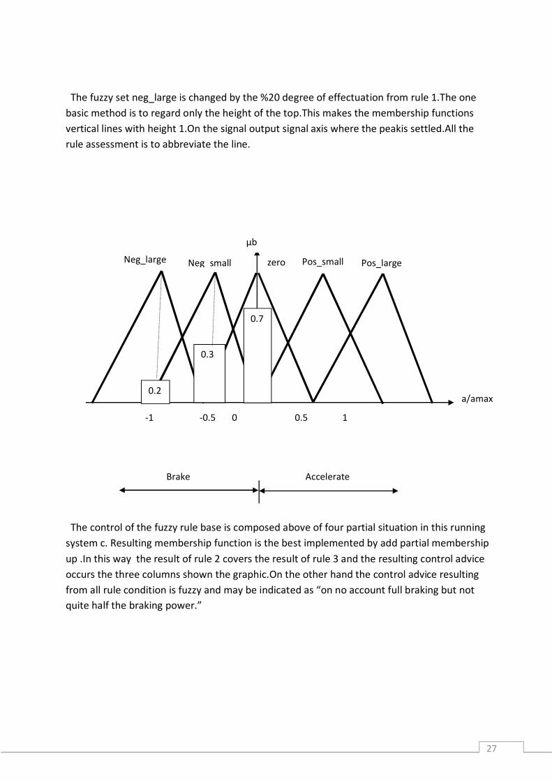
The fuzzy set neg_large is changed by the %20 degree of effectuation from rule 1.The one basic method is to regard only the height of the top.This makes the membership functions vertical lines with height 1.On the signal output signal axis where the peakis settled.All the rule assessment is to abbreviate the line.
The control of the fuzzy rule base is composed above of four partial situation in this running system c. Resulting membership function is the best implemented by add partial membership up .In this way the result of rule 2 covers the result of rule 3 and the resulting control advice occurs the three columns shown the graphic.On the other hand the control advice resulting from all rule condition is fuzzy and may be indicated as “on no account full braking but not quite half the braking power.”
µb
Pos_small Pos_large
Brake Accelerate
-1 -0.5 0 0.5 1
Neg_large Neg_small zero
a/amax 0.2
0.3
0.7

28
4.4 Defuzzification
From the control advice we have to calculate a non-fuzzy numeric value for the control variable as a numeric value.The resulting membership function is composed of the superimposition of partial areas of triangles and trapezoids the position of the center of gravity of the total area on the output signal axis is the non-fuzzy value investigated[7].We can guess a mechanical system in which the three columns for the acceleration values that weight is a function of their height.The columns are balanced on a consist in along the axis.Then we can calculate the numeric control variable to find out the non-fuzzy value ; ∑ .∑
= . , . , . , . ,, , ,
≈ −0,3 (Siemens user`s manual)
If we consider the this example we can realize that vehicle’s brake is executed with approx %30 .
29
5. LABORATORY WORK
5.1 THE PROCESS AN EXAMPLE ON TEMPERATURE CONTROL
Tuning a temperature controller consist of setting the proportional, integral and derivative values to get the best possible control for a process. If the tuning temperature hasn’t got an autotune algorithm or if the autotune algorithm doesn’t support adequate control for the process the temperature control unit should be tuned using trial and error. The controller have a capacity of particular control stability when properly tuned and used. If we obtain the fastest response time and smallest overshoot by following these directives carefully that operator can be able to achieve. The information for tuning this three mode controller might be different from other controller tuning procedures. Tuning outputs for heating control is required to complete several stage .Primarily output is enabled for start the process and the process must be run at a set value that will allow the temperature to stabilize with heat input needed. When rate and reset is turned off the temperature will have stabilized with a steady state deviation or temperature will have dropped down between the set value and current temperature.
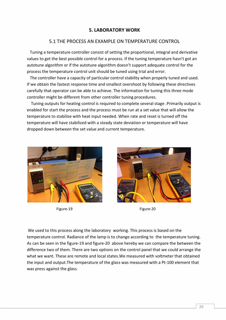
We used to this process along the laboratory working. This process is based on the temperature control. Radiance of the lamp is to change according to the temperature tuning. As can be seen in the figure-19 and figure-20 above hereby we can compare the between the difference two of them. There are two options on the control panel that we could arrange the what we want. These are remote and local states.We measured with voltmeter that obtained the input and output.The temperature of the glass was measured with a Pt-100 element that was press against the glass.
Figure-19 Figure-20
30
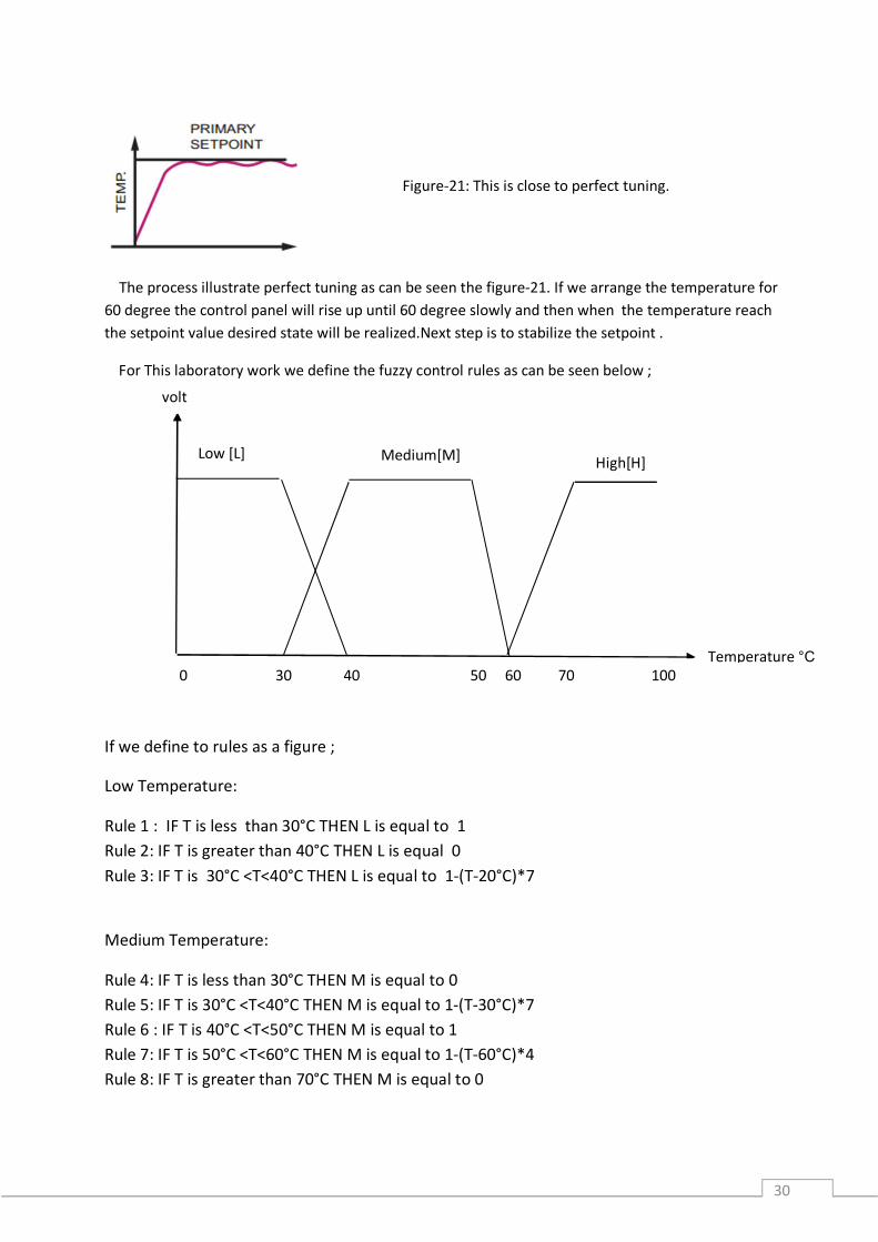
The process illustrate perfect tuning as can be seen the figure-21. If we arrange the temperature for 60 degree the control panel will rise up until 60 degree slowly and then when the temperature reach the setpoint value desired state will be realized.Next step is to stabilize the setpoint .
For This laboratory work we define the fuzzy control rules as can be seen below ;
If we define to rules as a figure ;
Low Temperature:
Rule 1 : IF T is less than 30°C THEN L is equal to 1 Rule 2: IF T is greater than 40°C THEN L is equal 0 Rule 3: IF T is 30°C <T<40°C THEN L is equal to 1-(T-20°C)*7
Medium Temperature:
Rule 4: IF T is less than 30°C THEN M is equal to 0 Rule 5: IF T is 30°C <T<40°C THEN M is equal to 1-(T-30°C)*7 Rule 6 : IF T is 40°C <T<50°C THEN M is equal to 1 Rule 7: IF T is 50°C <T<60°C THEN M is equal to 1-(T-60°C)*4 Rule 8: IF T is greater than 70°C THEN M is equal to 0
Figure-21: This is close to perfect tuning.
Temperature °C
volt
Low [L] Medium[M]
0 30 40 50 60 70 100
High[H]
31
High Temperature : Rule 9: IF T is less than 60°C THEN H is equal to 0 Rule 10: IF 60°C <T<70°C THEN H is equal to (T-60°C)*7 Rule 11: IF T is greater than 70°C THEN H is equal to 1
5.2 Output from the to The Process input on Fuzzy control
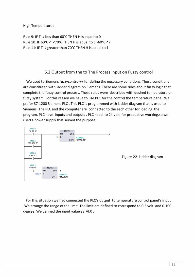
We used to Siemens fuzzycontrol++ for define the necessary conditions. These conditions are constituted with ladder diagram on Siemens. There are some rules about fuzzy logic that complete the fuzzy control process. These rules were described with desired temperature on fuzzy system. For this reason we have to use PLC for the control the temperature panel. We prefer S7-1200 Siemens PLC . This PLC is programmed with ladder diagram that is used to Siemens. The PLC and the computer are connected to the each other for loading the program. PLC have inputs and outputs . PLC need to 24 volt for productive working.so we used a power supply that served the purpose.
For this situation we had connected the PLC’s output to temperature control panel’s input .We arrange the range of the limit .The limit are defined to correspond to 0-5 volt and 0-100 degree. We defined the input value as AI.0 .
Figure-22 ladder diagram
32
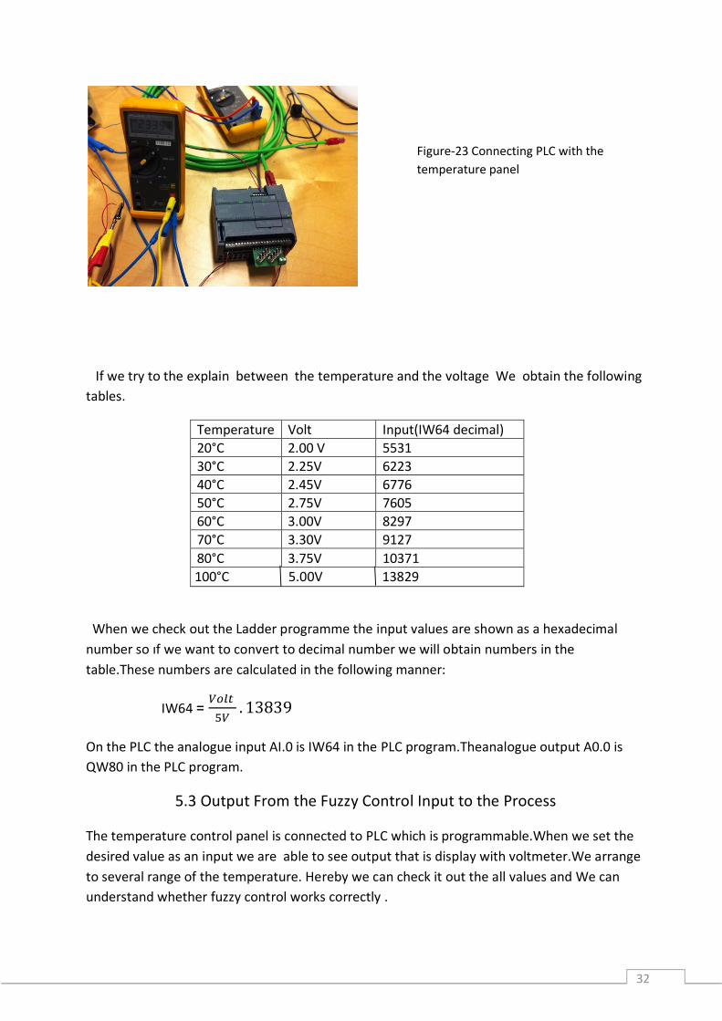
If we try to the explain between the temperature and the voltage We obtain the following tables.
Temperature Volt Input(IW64 decimal) 20°C 2.00 V 5531 30°C 2.25V 6223 40°C 2.45V 6776 50°C 2.75V 7605 60°C 3.00V 8297 70°C 3.30V 9127 80°C 3.75V 10371 100°C 5.00V 13829
When we check out the Ladder programme the input values are shown as a hexadecimal number so ıf we want to convert to decimal number we will obtain numbers in the table.These numbers are calculated in the following manner:
IW64 = . 13839
On the PLC the analogue input AI.0 is IW64 in the PLC program.Theanalogue output A0.0 is QW80 in the PLC program.
5.3 Output From the Fuzzy Control Input to the Process
The temperature control panel is connected to PLC which is programmable.When we set the desired value as an input we are able to see output that is display with voltmeter.We arrange to several range of the temperature. Hereby we can check it out the all values and We can understand whether fuzzy control works correctly .
Figure-23 Connecting PLC with the temperature panel
33
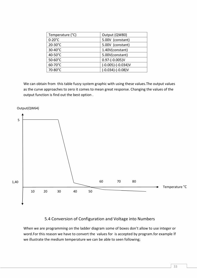
Temperature (°C) Output (QW80) 0-20°C 5.00V (constant) 20-30°C 5.00V (constant) 30-40°C 1.40V(constant) 40-50°C 5.00V(constant) 50-60°C 0.97-(-0.005)V 60-70°C (-0.005)-(-0.034)V 70-80°C (-0.034)-(-0.08)V
We can obtain from this table fuzzy system graphic with using these values.The output values as the curve approaches to zero it comes to mean great response. Changing the values of the output function is find out the best option .
5.4 Conversion of Configuration and Voltage into Numbers
When we are programming on the ladder diagram some of boxes don’t allow to use integer or word.For this reason we have to convert the values for is accepted by program.for example İf we illustrate the medium temperature we can be able to seen following;
Output(QW64)
10 20 30 40 50 Temperature °C
5
1,40 60 70 80
34
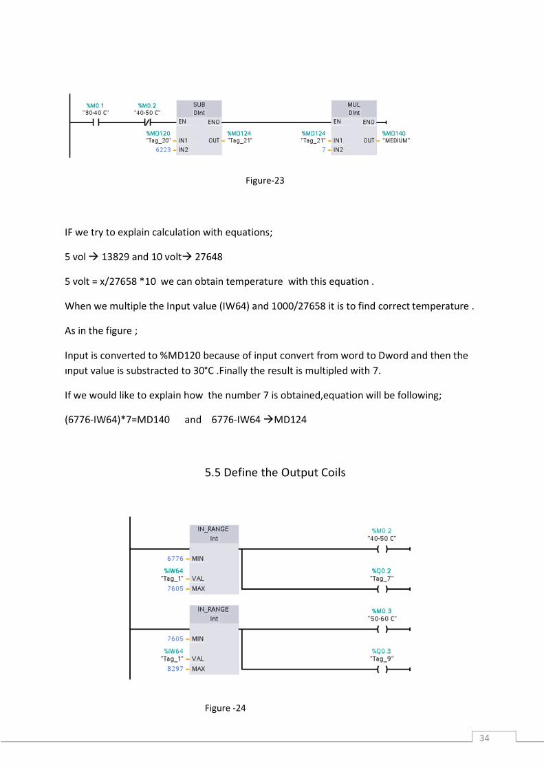
IF we try to explain calculation with equations;
5 vol 13829 and 10 volt 27648
5 volt = x/27658 *10 we can obtain temperature with this equation .
When we multiple the Input value (IW64) and 1000/27658 it is to find correct temperature .
As in the figure ;
Input is converted to %MD120 because of input convert from word to Dword and then the ınput value is substracted to 30°C .Finally the result is multipled with 7.
If we would like to explain how the number 7 is obtained,equation will be following;
(6776-IW64)*7=MD140 and 6776-IW64 MD124
5.5 Define the Output Coils
Figure-23
Figure -24
35
We use the ladder diagram for Siemens PLC and this programme language is required to some rules when we constitute some conditions.After we determine the range of the temperature we have to defined to output coils otherwise PLC don’t generate the output response.
Range of the temperature in numbers Number of the coil(output) 0-6223 M0.0 6223-6776 M0.1 6776-7605 M0.2 7605-8297 M0.3 6776-9127 M0.4 9127-13829 M0.5 10371-15000 M0.6
5.6 Fuzz Set for L(Low),M(Medium) and H(High) Temperature
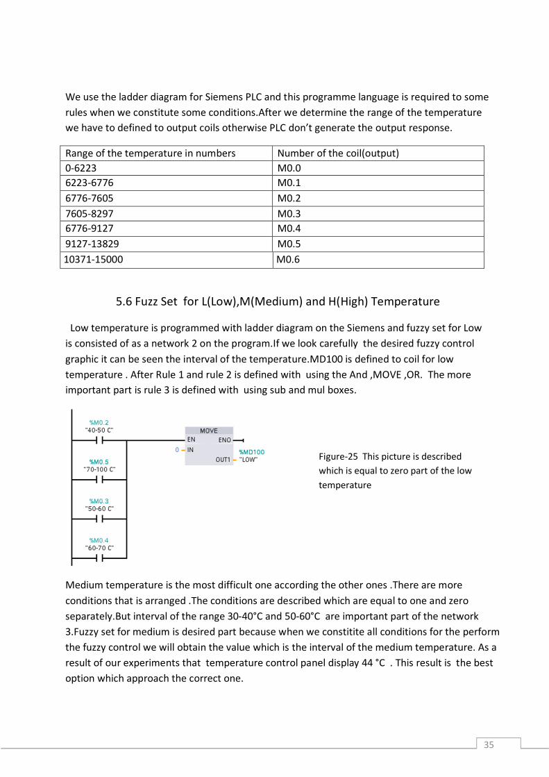
Low temperature is programmed with ladder diagram on the Siemens and fuzzy set for Low is consisted of as a network 2 on the program.If we look carefully the desired fuzzy control graphic it can be seen the interval of the temperature.MD100 is defined to coil for low temperature . After Rule 1 and rule 2 is defined with using the And ,MOVE ,OR. The more important part is rule 3 is defined with using sub and mul boxes.
Medium temperature is the most difficult one according the other ones .There are more conditions that is arranged .The conditions are described which are equal to one and zero separately.But interval of the range 30-40°C and 50-60°C are important part of the network 3.Fuzzy set for medium is desired part because when we constitite all conditions for the perform the fuzzy control we will obtain the value which is the interval of the medium temperature. As a result of our experiments that temperature control panel display 44 °C . This result is the best option which approach the correct one.
Figure-25 This picture is described which is equal to zero part of the low temperature
36
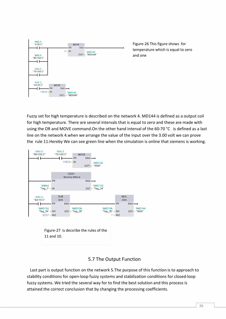
Fuzzy set for high temperature is described on the network 4. MD144 is defined as a output coil for high temperature. There are several intervals that is equal to zero and these are made with using the OR and MOVE command.On the other hand interval of the 60-70 °C is defined as a last line on the network 4.when we arrange the value of the input over the 3.00 volt we can prove the rule 11.Hereby We can see green line when the simulation is online that siemens is working.
5.7 The Output Function
Last part is output function on the network 5.The purpose of this function is to approach to stability conditions for open-loop fuzzy systems and stabilization conditions for closed-loop fuzzy systems. We tried the several way for to find the best solution and this process is attained the correct conclusion that by changing the processing coefficients.
Figure-26 This figure shows for temperature which is equal to zero and one
Figure-27 is decsribe the rules of the 11 and 10.
37
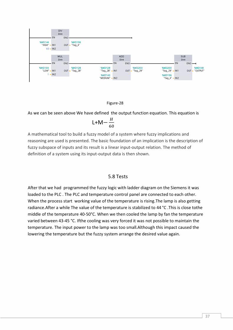
As we can be seen above We have defined the output function equation. This equation is
A mathematical tool to build a fuzzy model of a system where fuzzy implications and reasoning are used is presented. The basic foundation of an implication is the description of fuzzy subspace of inputs and its result is a linear input-output relation. The method of definition of a system using its input-output data is then shown.
5.8 Tests
After that we had programmed the fuzzy logic with ladder diagram on the Siemens it was loaded to the PLC . The PLC and temperature control panel are connected to each other. When the process start working value of the temperature is rising.The lamp is also getting radiance.After a while The value of the temperature is stabilized to 44 °C .This is close tothe middle of the temperature 40-50°C. When we then cooled the lamp by fan the temperature varied between 43-45 °C. Ifthe cooling was very forced it was not possible to maintain the temperature. The input power to the lamp was too small.Although this impact caused the lowering the temperature but the fuzzy system arrange the desired value again.
Figure-28
L+M−
38
6. SUMMATION
Fuzzy systems are showing great guarantee in consumer products,industrial and commercial systems and decision support system.The term fuzzy indicates to the capability od dealing with indefinite or vague inputs.Instead of coplex mathematical methods fuzzy logic users must have verbal conditions to define the relationship between the input information and the output information.Fuzzy logic have access to suitable and user friendly front end to improvable control programs.Another advantages are help to designers focus on the functional objectives not on the mathematical equations.Fuzzy logic is a pretty influential tool that is monopolizing most of field and signing thriving applications. The results of testing on the real plant prove which the remedy fuzzy systems controller is able to precision to variation of the reference temperature attention. In a fuzzy controller data passes through a pre-processing block a controller and a post processing block.Pre-processing include of a linear or nonlinear scaling,as weel as a quantization when using dicrete membership functions and if we talk about continuous membership functions the membership of each input measurement is looked up in a function[4]. When designing the rule base the designer should regard the number of terms set, their shape and their overlap. In this project I have presented the steps required to illustrate fuzzy controllers. Such controllers, when integrated into systems that handle sensitiveness values, require a translation process before and after the reasoning method is applied. Hence the three-step structure of fuzzy controllers: fuzzification, inference and defuzzification. The different stages were explained using an example including temperature control. This is a trivial, problem that can be succeeded using many techniques, such as with a classical PID controller.However, I have used this example to solve the design of a fuzzy controller, as well as its mode of operation.
39
REFERENCES
[1] fuzzy contol system Wikipedia
[2]”Fuzzy logic” Stanford encyclopedia of philosophy ,Stanford university 2006/07/23
[3]Ian S.Show and Marcelo G.Simoes M.G. (1999) controle modelagen fuzzy,Edgard Bluchert company Ian S.Show (1998) fuzzy control of industrial systems theory and applications Kluwer academic publishers
[4] foundations of fuzzy contrl Jan jantzen 2007 johnWiley&sons
[5] Marcelo Godoy Simoes,Colorada school of mines engineering division(introduction to fuzzy control)
[6] labView PID and fuzzy logic toolkit user manual
[7] Siemens fuzzy control user’s manual
[9]www.ni.com

40