Embed Size (px)
Citation preview
Module 1 Regulations & Standards Lesson 1 Regulatory Environment
Assignment #1:
Regulatory Environment
Tasks 1. Find and compare the definitions of a “medical device”’ under
US/FDQA, EU/MDD, TPD/canMedDevReg and GHTF.
2. Check the definition of “sale” under the canMedDevReg.
3. Construct a table showing the following for the US, Canada and the EU:
(i) The regulation
(ii) The classes
(iii) Design control requirements
(iv) Controlling body
BMET 7102 Copyright © 2003 BCIT 2/27/03 Page 0
Module 1 Regulations & Standards Lesson 2 Pre-design Activities
Assignment #2:
Classification of Medical Devices
Tasks
Exercise 1 The company XYZ plans to develop an oral electronic thermometer OREL-T with a digital display. The thermometer will be battery powered, and a battery charger will be supplied with the device. In order to shorten the time for displaying a valid temperature, the device will include a predictive algorithm.
Determine the classification (including Software ”Level of Concern”) of the OREL-T under US/FDA, EU/MDD and Canada/TPD regulations.
Exercise 2 The company QAZ plans to develop a baby cradle for prematurely born babies. The cradle includes a heater, and a digital display of temperature. The target temperature can be set, and an alarm will sound if the cradle temperature deviates more than 2 degrees from the set temperature.
Determine the classification (including Software ”Level of Concern”) of the baby cradle under US/FDA, EU/MDD and Canada/TPD regulations.
BMET 7102 Copyright © 2003 BCIT 2/27/03 Page 0
Module 1 Regulations & Standards Lesson 3 Lifecycles
Assignment #3:
Lifecycle Models
This is a self-study assignment. Do not hand in. Once you have completed the assignment, study the solutions and compare them with your answers.
Tasks 1. Generate a table showing pros and cons of the Waterfall and Spiral
models.
2. How could the Waterfall model be adapted to achieve some of the Spiral model’s advantages?
3. Check your assignment against the answers provided.
BMET 7102 Copyright © 2003 BCIT 2/27/03 Page 0
Module 1 Regulations & Standards Lesson 4 Standards
Assignment #4:
Medical Device Standards
This is a self-study assignment. Do not hand in. Once you have completed the assignment, study the solutions and compare them with your answers.
Tasks
EXERCISE 1 For the oral electronic thermometer OREL-T (see Lesson 2 Pre-design Activities), list the standards with which you feel the device should comply.
Consider that the device would be marketed in the US, Canada and the European Union.
Check your assignment against the answers provided.
EXERCISE 2 Search the Internet for sources of standards and then bookmark them. In this exercise the focus is on locating medical device standards (i.e.—standards you have been exposed to in this lesson). Include the following Web –sites in your search:
• www.csa-intl.org/onlinestore
• www.iec.ch (go to the webstore)
• www.iso.ch (go to the ISO store)
• www.standards.ieee.org
• www.webstore.ansi.org
• www.marketplace.aami.org
Look through these Web sites to get an idea of what is available. For the standards that are now familiar to you, read the scope of that standard.
BMET 7102 Copyright © 2003 BCIT 2/27/03 Page 0
Module 2 Design Control Lesson 5 Risk Management
Assignment #5:
Risk Analysis
This is a self-study assignment. Do not hand in. Once you have completed the assignment, study the solutions and compare them with your answers.
Tasks
Exercise 1 Determine five possible hazards relating to the use of an X-ray machine. Assess the hazards and determine the risk level. For risks of R3 and R4, propose mitigation and re-assess.
Exercise 2 Describe the principal differences between FMEA and FTA.
Check your assignment against the answers provided.
BMET 7102 Copyright © 2003 BCIT 2/27/03 Page 0
Module 2 Design Control Lesson 6 Design Planning
Assignment #6:
Design and Development Planning
Introduction To write a design and development plan for medical devices is usually a complex task. The complexity arises from having to bring together a number of different experts and/or departments to focus on a single project. Furthermore, projects typically contain many unknowns. Hence, assumptions are required. As the project proceeds and more facts become known, the design and development plans are updated. The design and development plan includes the following: project goals and objectives, organizational chart with defined project responsibilities, definition of the major tasks, project schedule, identification of reviewers, project and design reviews.
In order not to lose sight of the basic ideas a simple example of a measurement device (i.e. a device to measure a magnetic field) is used. It is not the intent of this example to provide a complete design and development plan, but rather to give the student a better appreciation of how a project can be structured. The focus is on the project schedule. The project schedule shows all the project tasks in an appropriate time sequence and dependence. Please note that the device described below actually has been build by Biomedical Engineering Technology students according to a project schedule. To develop the device, the students applied methodologies that are consistent with design controls.
To develop a project schedule one must first gain a general understanding of the project and the unknowns. Unknowns are resolved by making reasonable assumptions. These assumptions will be reviewed as the project evolves. In this assignment the student is given more information on the device than is usually available during the initial stages of a project. By applying design control methodology and using the information given below, the student will be able to develop a project schedule.
Tasks 1. Study the functional description; the requirement specifications; the
block-diagram; and the project plan of the “MagnetoMeter.”
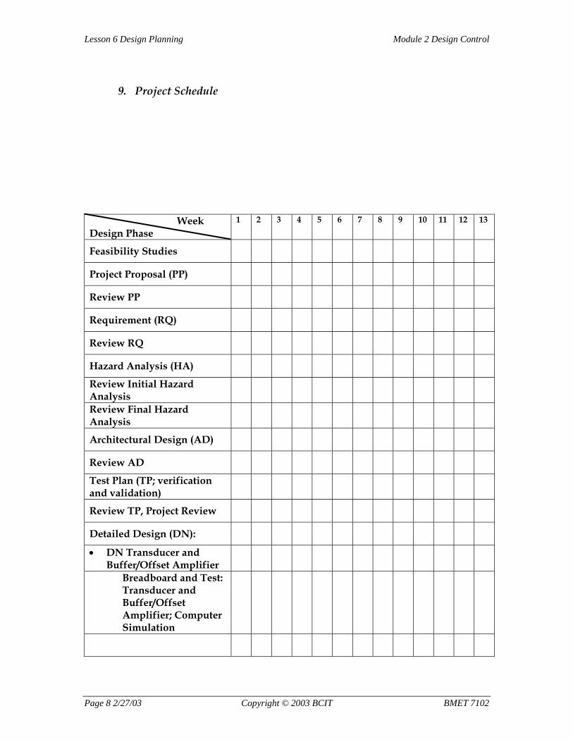
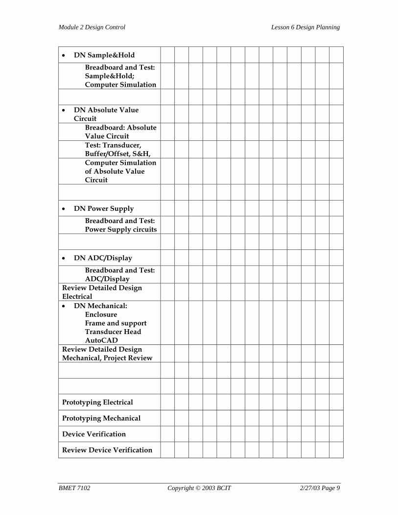
2. Complete the development schedule for this project. The project matrix is included in the project design and development plan. Include the following items:
BMET 7102 Copyright © 2003 BCIT 2/27/03 Page
Module 2 Design Control Lesson 6 Design Planning
• In the project matrix, indicate with an “X” the week(s) allocated for each task. Note: For this project, one week is the smallest “block” of time allocated.
• Mark each review with an “R” in the project matrix.
• Make an assumption as to how long each task will take to complete. Assume there are sufficient resources for the project to be completed in 13 weeks.
3. Show dependencies between tasks (i.e.—a task or tasks must be complete before another can start) with vertical lines.
4. In the process you must:
• Determine how the project tasks relate to each other and in what sequence they should be carried out.
• Make an assumption as to how long each task will take to complete.
• Determine when reviews will be held.
5. Hand in the completed project schedule.
6. Once you have received feedback from the instructor together with a solution, compare it with your solution.
BMET 7102 Copyright © 2003 BCIT 2/27/03 Page 1
Lesson 6 Design Planning Module 2 Design Control
Magnetic Field Sensor Measurement Device (MagnetoMeter)
I. Functional Description The purpose of this device is to measure a magnetic field, B (magnetic flux density in Tesla or Gauss) from a variety of sources found in the medical environment. These include magneto-encephalographic system (MEG), magnetic resonance imaging (MRI), EMI/EMC interference mapping, and many secondary uses (for example, pacemakers, laboratory equipment, rotating X-ray anode, et cetera). The device has been classified (preliminary assessment by the FDA) as a class I device. The functional specifications are as follows:
• Measures the maximum magnetic flux density, B, in any particular direction
• Input: low magnetic flux in the range of 0 to ±800 Gauss or 0 to ±80 mT
• Output: magnetic flux in Gauss, digital display
• Measurement Modes (sampling mode): continuous and peak detection
• Acquisition Time: fast
• Accuracy/linearity/precision: high
• Handheld device, portable
• Battery or external power supply
• Use in a medical environment
Note: During the measurement interval, defined by the measurement mode, the maximum magnetic flux, B, is measured. Since B is direction dependent, the maximum B depends on the x-y-z positions of the MagnetoMeter.
Page 2 2/27/03 Copyright © 2003 BCIT BMET 7102
Module 2 Design Control Lesson 6 Design Planning
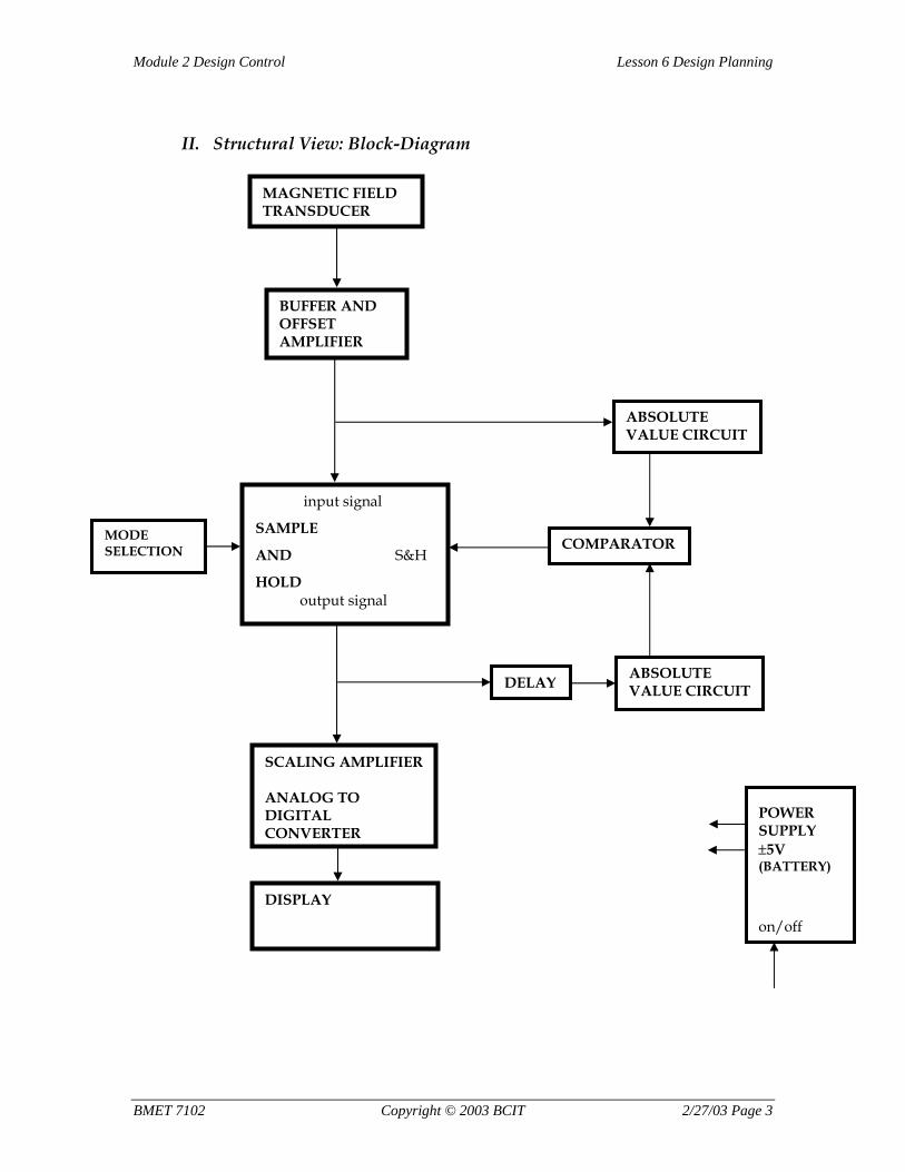
II. Structural View: Block-Diagram
BUFFER AND OFFSET AMPLIFIER
input signal
SAMPLE
AND S&H
HOLD output signal
ABSOLUTE VALUE CIRCUIT
ABSOLUTE VALUE CIRCUIT
COMPARATOR
SCALING AMPLIFIER ANALOG TO DIGITAL CONVERTER
DISPLAY
POWER SUPPLY ±5V (BATTERY) on/off
DELAY
MODE SELECTION
MAGNETIC FIELD TRANSDUCER
BMET 7102 Copyright © 2003 BCIT 2/27/03 Page 3
Lesson 6 Design Planning Module 2 Design Control
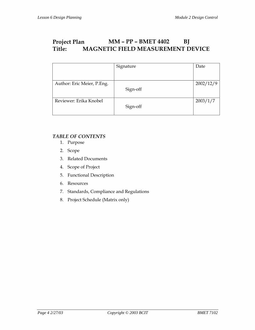
Project Plan Title: MAGNETIC FIELD MEASUREMENT DEVICE
MM – PP – BMET 4402 BJ
Signature Date
Author: Eric Meier, P.Eng. Sign-off
2002/12/9
Reviewer: Erika Knobel Sign-off
2003/1/7
TABLE OF CONTENTS 1. Purpose
2. Scope
3. Related Documents
4. Scope of Project
5. Functional Description
6. Resources
7. Standards, Compliance and Regulations
8. Project Schedule (Matrix only)
Page 4 2/27/03 Copyright © 2003 BCIT BMET 7102
Module 2 Design Control Lesson 6 Design Planning
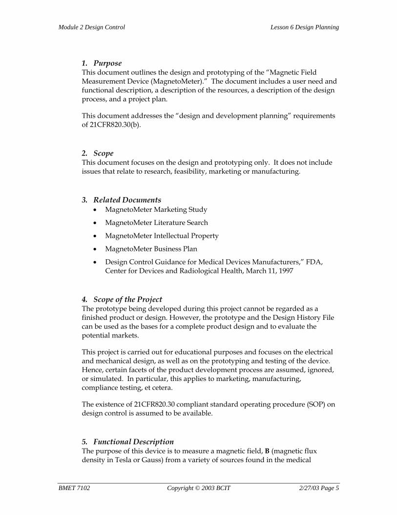
1. Purpose This document outlines the design and prototyping of the “Magnetic Field Measurement Device (MagnetoMeter).” The document includes a user need and functional description, a description of the resources, a description of the design process, and a project plan.
This document addresses the “design and development planning” requirements of 21CFR820.30(b).
2. Scope This document focuses on the design and prototyping only. It does not include issues that relate to research, feasibility, marketing or manufacturing.
3. Related Documents • MagnetoMeter Marketing Study
• MagnetoMeter Literature Search
• MagnetoMeter Intellectual Property
• MagnetoMeter Business Plan
• Design Control Guidance for Medical Devices Manufacturers,” FDA, Center for Devices and Radiological Health, March 11, 1997
4. Scope of the Project The prototype being developed during this project cannot be regarded as a finished product or design. However, the prototype and the Design History File can be used as the bases for a complete product design and to evaluate the potential markets.
This project is carried out for educational purposes and focuses on the electrical and mechanical design, as well as on the prototyping and testing of the device. Hence, certain facets of the product development process are assumed, ignored, or simulated. In particular, this applies to marketing, manufacturing, compliance testing, et cetera.
The existence of 21CFR820.30 compliant standard operating procedure (SOP) on design control is assumed to be available.
5. Functional Description The purpose of this device is to measure a magnetic field, B (magnetic flux density in Tesla or Gauss) from a variety of sources found in the medical
BMET 7102 Copyright © 2003 BCIT 2/27/03 Page 5
Lesson 6 Design Planning Module 2 Design Control
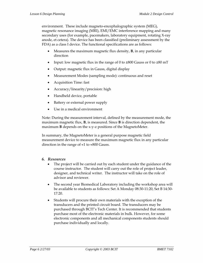
environment. These include magneto-encephalographic system (MEG), magnetic resonance imaging (MRI), EMI/EMC interference mapping and many secondary uses (for example, pacemakers, laboratory equipment, rotating X-ray anode, et cetera). The device has been classified (preliminary assessment by the FDA) as a class I device. The functional specifications are as follows:
• Measures the maximum magnetic flux density, B, in any particular direction
• Input: low magnetic flux in the range of 0 to ±800 Gauss or 0 to ±80 mT
• Output: magnetic flux in Gauss, digital display
• Measurement Modes (sampling mode): continuous and reset
• Acquisition Time: fast
• Accuracy/linearity/precision: high
• Handheld device, portable
• Battery or external power supply
• Use in a medical environment
Note: During the measurement interval, defined by the measurement mode, the maximum magnetic flux, B, is measured. Since B is direction dependent, the maximum B depends on the x-y-z positions of the MagnetoMeter.
In summary, the MagnetoMeter is a general purpose magnetic field measurement device to measure the maximum magnetic flux in any particular direction in the range of ≈1 to ≈800 Gauss.
6. Resources • The project will be carried out by each student under the guidance of the
course instructor. The student will carry out the role of project leader, designer, and technical writer. The instructor will take on the role of advisor and reviewer.
• The second year Biomedical Laboratory including the workshop area will be available to students as follows: Set A Monday 08:30-11:20, Set B 14:30-17:20.
• Students will procure their own materials with the exception of the transducers and the printed circuit board. The transducers may be purchased through BCIT’s Tech Center. It is recommended that students purchase most of the electronic materials in bulk. However, for some electronic components and all mechanical components students should purchase individually and locally.
Page 6 2/27/03 Copyright © 2003 BCIT BMET 7102
Module 2 Design Control Lesson 6 Design Planning
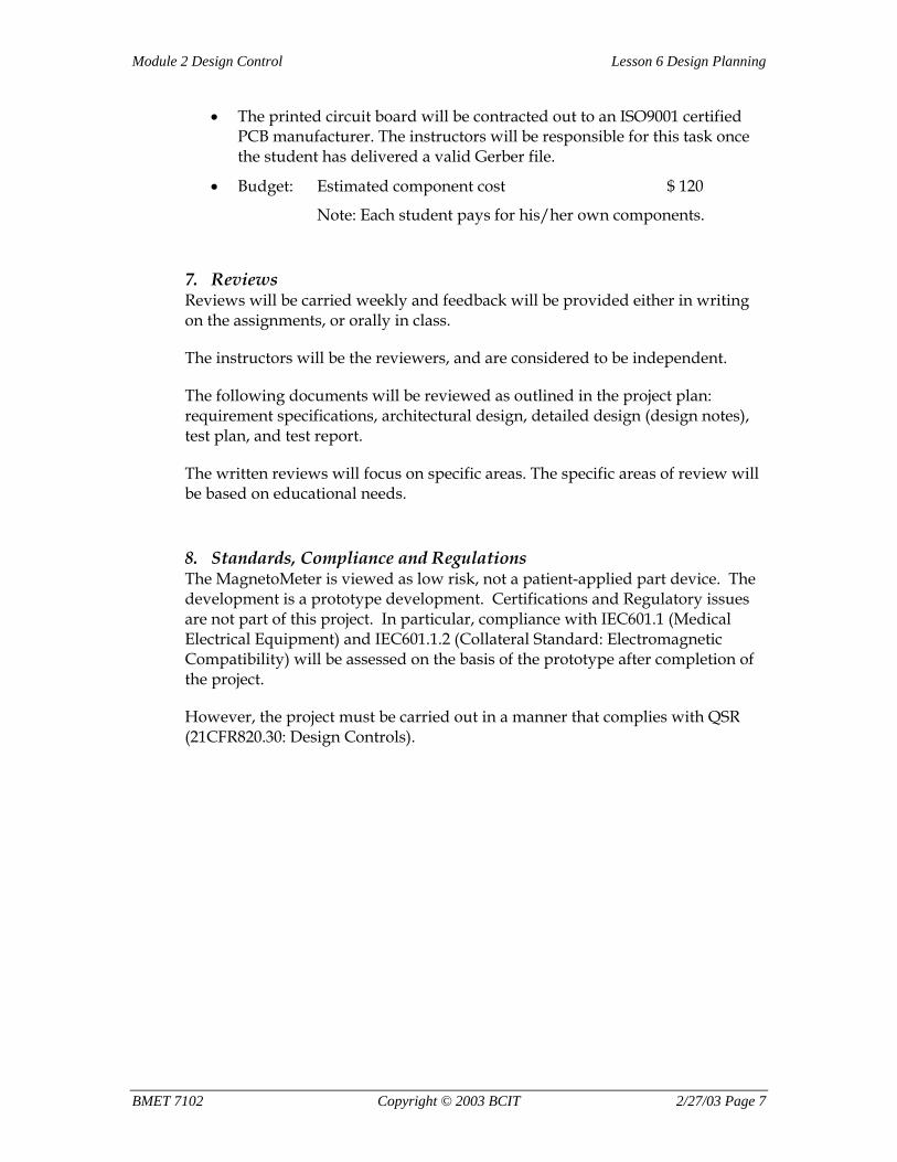
• The printed circuit board will be contracted out to an ISO9001 certified PCB manufacturer. The instructors will be responsible for this task once the student has delivered a valid Gerber file.
• Budget: Estimated component cost $ 120
Note: Each student pays for his/her own components.
7. Reviews Reviews will be carried weekly and feedback will be provided either in writing on the assignments, or orally in class.
The instructors will be the reviewers, and are considered to be independent.
The following documents will be reviewed as outlined in the project plan: requirement specifications, architectural design, detailed design (design notes), test plan, and test report.
The written reviews will focus on specific areas. The specific areas of review will be based on educational needs.
8. Standards, Compliance and Regulations The MagnetoMeter is viewed as low risk, not a patient-applied part device. The development is a prototype development. Certifications and Regulatory issues are not part of this project. In particular, compliance with IEC601.1 (Medical Electrical Equipment) and IEC601.1.2 (Collateral Standard: Electromagnetic Compatibility) will be assessed on the basis of the prototype after completion of the project.
However, the project must be carried out in a manner that complies with QSR (21CFR820.30: Design Controls).
BMET 7102 Copyright © 2003 BCIT 2/27/03 Page 7
Lesson 6 Design Planning Module 2 Design Control
9. Project Schedule Week Design Phase
1 2 3 4 5 6 7 8 9 10 11 12 13
Feasibility Studies
Project Proposal (PP)
Review PP
Requirement (RQ)
Review RQ
Hazard Analysis (HA)
Review Initial Hazard Analysis
Review Final Hazard Analysis
Architectural Design (AD)
Review AD
Test Plan (TP; verification and validation)
Review TP, Project Review
Detailed Design (DN):
• DN Transducer and Buffer/Offset Amplifier
Breadboard and Test: Transducer and Buffer/Offset Amplifier; Computer Simulation
Page 8 2/27/03 Copyright © 2003 BCIT BMET 7102
Module 2 Design Control Lesson 6 Design Planning
• DN Sample&Hold
Breadboard and Test: Sample&Hold; Computer Simulation
• DN Absolute Value Circuit
Breadboard: Absolute Value Circuit
Test: Transducer, Buffer/Offset, S&H,
Computer Simulation of Absolute Value Circuit
• DN Power Supply
Breadboard and Test: Power Supply circuits
• DN ADC/Display
Breadboard and Test: ADC/Display
Review Detailed Design Electrical
• DN Mechanical: Enclosure Frame and support Transducer Head AutoCAD
Review Detailed Design Mechanical, Project Review
Prototyping Electrical
Prototyping Mechanical
Device Verification
Review Device Verification
BMET 7102 Copyright © 2003 BCIT 2/27/03 Page 9
Lesson 6 Design Planning Module 2 Design Control
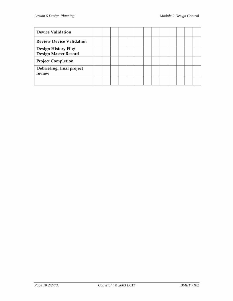
Device Validation
Review Device Validation
Design History File/ Design Master Record
Project Completion
Debriefing, final project review
Page 10 2/27/03 Copyright © 2003 BCIT BMET 7102
Module 2 Design Control Lesson 7 Design Input
Assignment #7:
Requirements
Introduction Writing requirement specifications for a medical device is typically a complex task. The starting point is the functional requirement (user needs). These need to be “translated” into a set of unambiguous, quantifiable and self-consistent requirements.
In order not to lose sight of the basic ideas of valid requirement, this assignment involves a simple example of a measurement device (i.e.—a device to measure gas pressure). This example is not intended to provide a complete requirement specification document, but rather to give the student a better appreciation of what writing a requirement entails. Please note that the device described below actually has been build by Biomedical Engineering Technology students. To develop the device, the students applied methodologies that are consistent with design controls.
The key to writing a requirement document is a clear understanding of the user needs. Based on these, a requirement specification document can be written. Each requirement includes a reference, a description and a measurable requirement. Quantitative limits should be expressed with a measurement tolerance. The environment in which the device is to be used should be properly defined, and appropriate standards should be included.
Tasks 1. Study the functional description, the requirement specifications and the
block-diagram of the “PressureMeter.”
2. Write the R12-E-a, R12-E-b and R12-E-c requirements for the functional specification “handheld and portable.”
3. Write the R1-S* requirement for the “pressure range.”
4. Write the R2-S* requirement for the functional specification “accuracy.”
5. Write the R13-E requirement using an appropriate standard for “electromagnetic compatibility.”
6. Hand in the requirements R1, R2, R12 and R13.
BMET 7102 Copyright © 2003 BCIT 2/27/03 Page 0

Module 2 Design Control Lesson 7 Design Input
7. Once you have received feedback from the instructor together with a solution, compare it with yours.
BMET 7102 Copyright © 2003 BCIT 2/27/03 Page 1
Lesson 7 Design Input Module 2 Design Control
Pressure Sensor Measurement Device (PressureMeter)
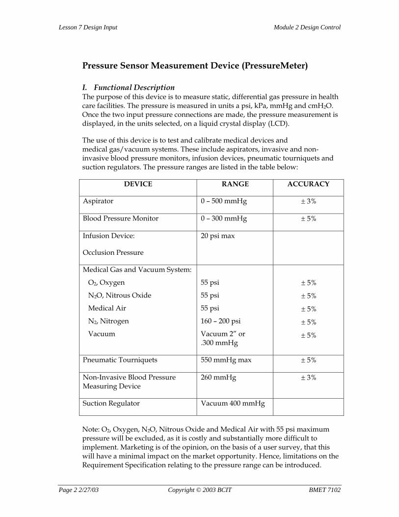
I. Functional Description The purpose of this device is to measure static, differential gas pressure in health care facilities. The pressure is measured in units a psi, kPa, mmHg and cmH2O. Once the two input pressure connections are made, the pressure measurement is displayed, in the units selected, on a liquid crystal display (LCD).
The use of this device is to test and calibrate medical devices and medical gas/vacuum systems. These include aspirators, invasive and non-invasive blood pressure monitors, infusion devices, pneumatic tourniquets and suction regulators. The pressure ranges are listed in the table below:
DEVICE RANGE ACCURACY
Aspirator 0 – 500 mmHg ± 3%
Blood Pressure Monitor 0 – 300 mmHg ± 5%
Infusion Device:
Occlusion Pressure
20 psi max
Medical Gas and Vacuum System:
O2, Oxygen
N2O, Nitrous Oxide
Medical Air
N2, Nitrogen
Vacuum
55 psi
55 psi
55 psi
160 – 200 psi
Vacuum 2” or .300 mmHg
± 5%
± 5%
± 5%
± 5%
± 5%
Pneumatic Tourniquets 550 mmHg max ± 5%
Non-Invasive Blood Pressure Measuring Device
260 mmHg ± 3%
Suction Regulator Vacuum 400 mmHg
Note: O2, Oxygen, N2O, Nitrous Oxide and Medical Air with 55 psi maximum pressure will be excluded, as it is costly and substantially more difficult to implement. Marketing is of the opinion, on the basis of a user survey, that this will have a minimal impact on the market opportunity. Hence, limitations on the Requirement Specification relating to the pressure range can be introduced.
Page 2 2/27/03 Copyright © 2003 BCIT BMET 7102
Module 2 Design Control Lesson 7 Design Input
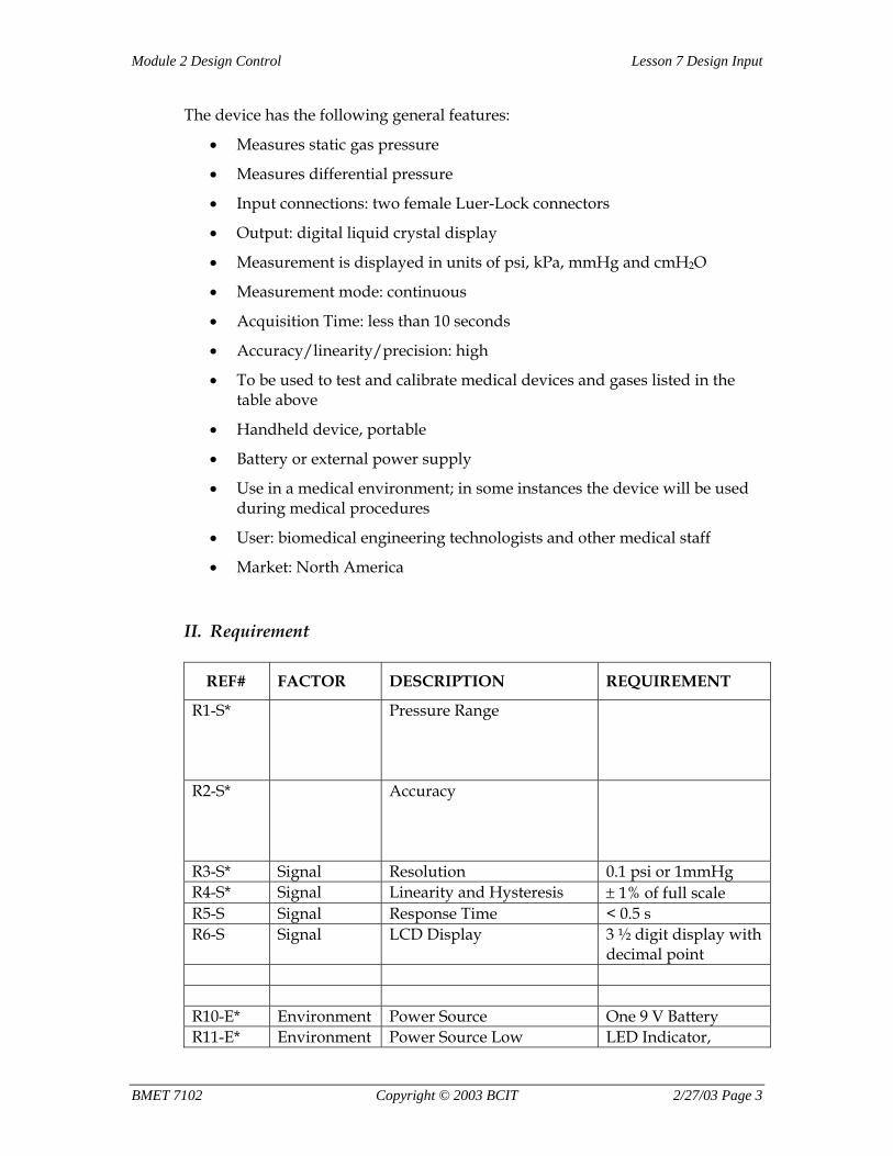
The device has the following general features:
• Measures static gas pressure
• Measures differential pressure
• Input connections: two female Luer-Lock connectors
• Output: digital liquid crystal display
• Measurement is displayed in units of psi, kPa, mmHg and cmH2O
• Measurement mode: continuous
• Acquisition Time: less than 10 seconds
• Accuracy/linearity/precision: high
• To be used to test and calibrate medical devices and gases listed in the table above
• Handheld device, portable
• Battery or external power supply
• Use in a medical environment; in some instances the device will be used during medical procedures
• User: biomedical engineering technologists and other medical staff
• Market: North America
II. Requirement
REF# FACTOR DESCRIPTION REQUIREMENT
R1-S* Pressure Range
R2-S* Accuracy
R3-S* Signal Resolution 0.1 psi or 1mmHg R4-S* Signal Linearity and Hysteresis ± 1% of full scale R5-S Signal Response Time < 0.5 s R6-S Signal LCD Display 3 ½ digit display with
decimal point R10-E* Environment Power Source One 9 V Battery R11-E* Environment Power Source Low LED Indicator,
BMET 7102 Copyright © 2003 BCIT 2/27/03 Page 3
Lesson 7 Design Input Module 2 Design Control
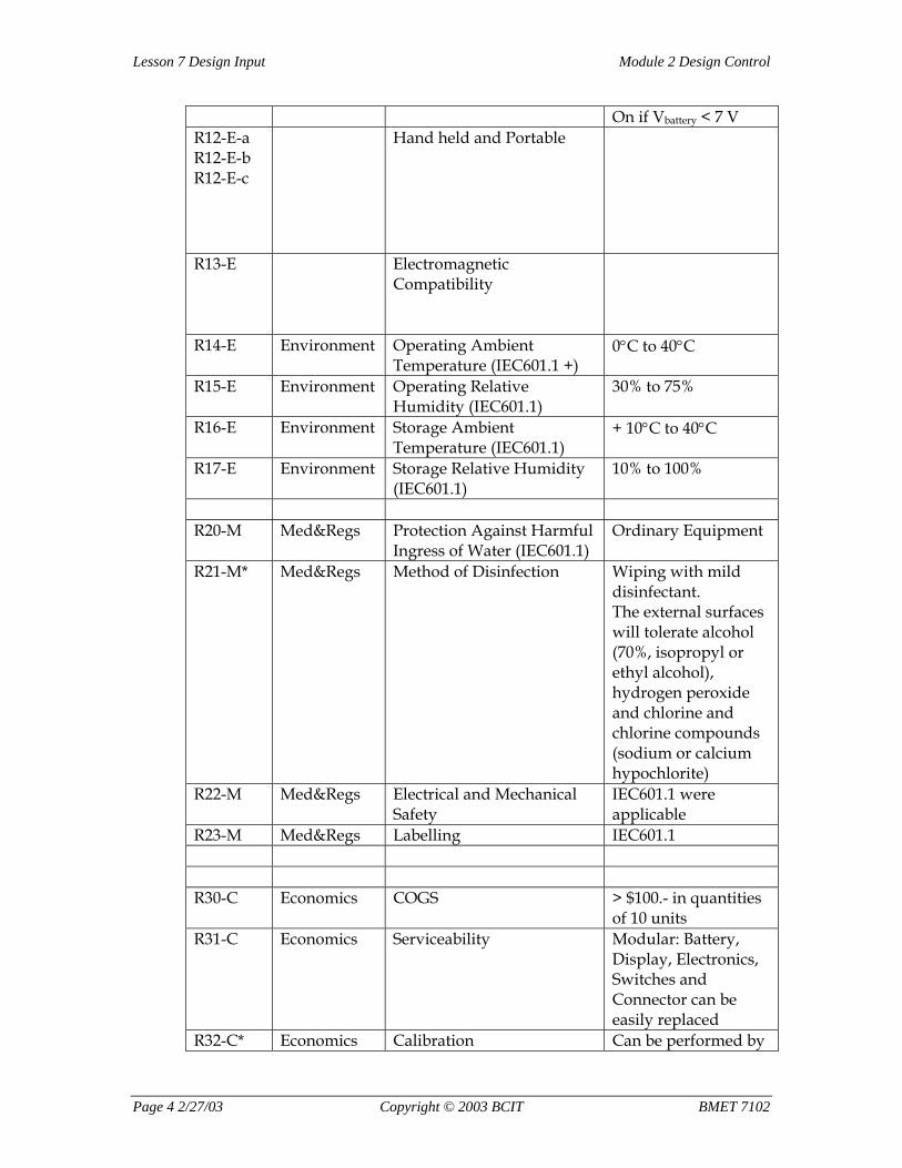
On if Vbattery < 7 V R12-E-a R12-E-b R12-E-c
Hand held and Portable
R13-E Electromagnetic Compatibility
R14-E Environment Operating Ambient Temperature (IEC601.1 +)
0°C to 40°C
R15-E Environment Operating Relative Humidity (IEC601.1)
30% to 75%
R16-E Environment Storage Ambient Temperature (IEC601.1)
+ 10°C to 40°C
R17-E Environment Storage Relative Humidity (IEC601.1)
10% to 100%
R20-M Med&Regs Protection Against Harmful
Ingress of Water (IEC601.1) Ordinary Equipment
R21-M* Med&Regs Method of Disinfection Wiping with mild disinfectant. The external surfaces will tolerate alcohol (70%, isopropyl or ethyl alcohol), hydrogen peroxide and chlorine and chlorine compounds (sodium or calcium hypochlorite)
R22-M Med&Regs Electrical and Mechanical Safety
IEC601.1 were applicable
R23-M Med&Regs Labelling IEC601.1 R30-C Economics COGS > $100.- in quantities
of 10 units R31-C Economics Serviceability Modular: Battery,
Display, Electronics, Switches and Connector can be easily replaced
R32-C* Economics Calibration Can be performed by
Page 4 2/27/03 Copyright © 2003 BCIT BMET 7102

Module 2 Design Control Lesson 7 Design Input
a non-technical person
R33-C Economics Lifetime 4 years Note: The essential requirements are marked with an asterisk (*).
BMET 7102 Copyright © 2003 BCIT 2/27/03 Page 5
Lesson 7 Design Input Module 2 Design Control
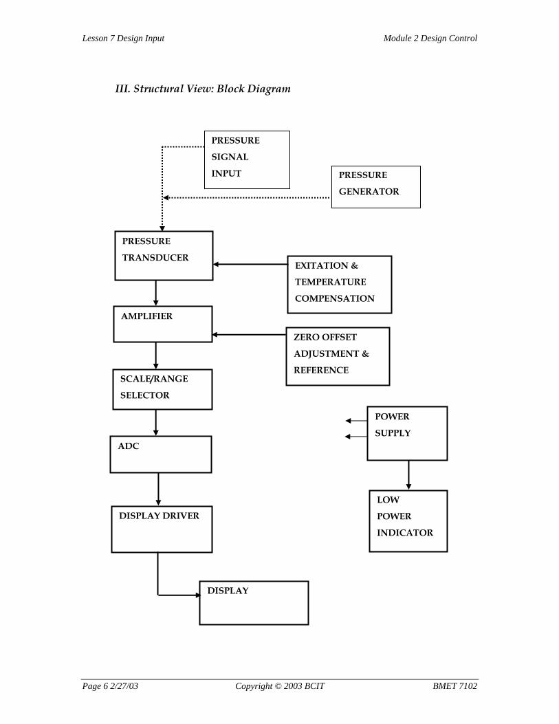
III. Structural View: Block Diagram
PRESSURE
SIGNAL
INPUT
PRESSURE
TRANSDUCER
PRESSURE
GENERATOR
EXITATION &
TEMPERATURE
COMPENSATION
AMPLIFIER
SCALE/RANGE
SELECTOR
DISPLAY DRIVER
DISPLAY
ZERO OFFSET
ADJUSTMENT &
REFERENCE
POWER
SUPPLY
LOW
POWER
INDICATOR
ADC
Page 6 2/27/03 Copyright © 2003 BCIT BMET 7102
Module 2 Design Control Lesson 8 Architectural Design and Detailed Requirements
Assignment #8:
Architectural Design
Introduction Writing an architectural design document is the first true design task. In this phase, a high level or system design is completed. The architectural design describes the system and sub-systems, establishes the principals of operation, defines the interfaces between sub-systems, and references internal system standards.
Most importantly, the Architectural Design establishes a structure to the design and project. As a result, the design and development plan will need to be reviewed and adjusted. In larger projects, writing detailed requirements for the sub-systems is also necessary.
In this assignment, which is designed to cover the basics of an Architectural Design, a simple example of a measurement device (i.e.—a device to measure peak illuminance in the visible spectrum) is used. It is not the intent of this assignment to provide a complete Architectural Design document, but rather to give the student a better appreciation of how a designs and projects can be structured.
The focus of this assignment is the structural view. The structural view shows all the sub-systems and how they relate to each other. Please note that Biomedical Engineering Technology students have actually built the device described below. To develop the device, the students applied methodologies consistent with design controls.
Tasks 1. Study the Concept, Functional Description and Requirements of the
“PeakIlluminanceMeter.”
2. Draw a detailed structural view (i.e.—block diagram) of the PeakIlluminanceMeter. Make sure to include the following:
• Label input and output variables
• Show the three wavelength band channels separately
• Show all sub-systems and how they relate to each other
• Show, but do not connect, the power supply unit
BMET 7102 Copyright © 2003 BCIT 2/27/03 Page 0
Module 2 Design Control Lesson 8 Architectural Design and Detailed Requirements
3. Hand in your detailed structural view. Note that there are many solutions to this problem.
4. Once you have received feedback from the instructor together with a solution, compare the solution provided with yours.
Peak Illuminance Measurement Device (PeakIlluminanceMeter, PIM)
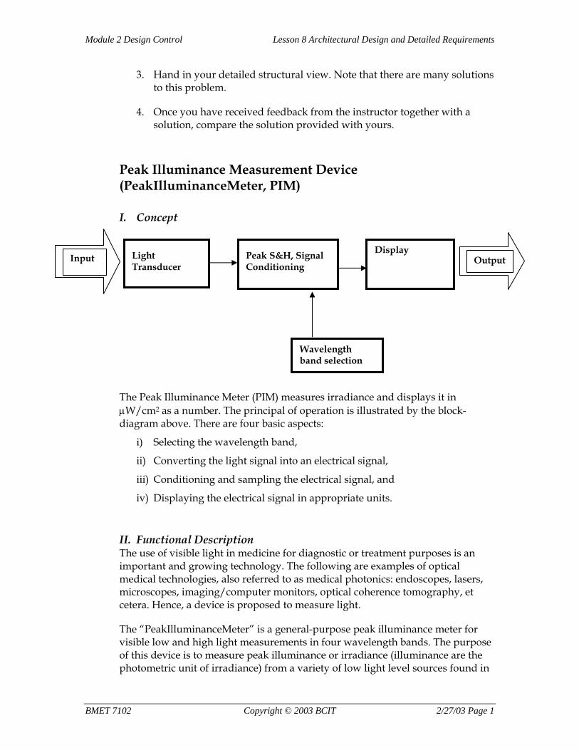
I. Concept
Light Transducer
Peak S&H, Signal Conditioning
Display Output Input
Wavelength band selection
The Peak Illuminance Meter (PIM) measures irradiance and displays it in µW/cm2 as a number. The principal of operation is illustrated by the block-diagram above. There are four basic aspects:
i) Selecting the wavelength band,
ii) Converting the light signal into an electrical signal,
iii) Conditioning and sampling the electrical signal, and
iv) Displaying the electrical signal in appropriate units.
II. Functional Description The use of visible light in medicine for diagnostic or treatment purposes is an important and growing technology. The following are examples of optical medical technologies, also referred to as medical photonics: endoscopes, lasers, microscopes, imaging/computer monitors, optical coherence tomography, et cetera. Hence, a device is proposed to measure light.
The “PeakIlluminanceMeter” is a general-purpose peak illuminance meter for visible low and high light measurements in four wavelength bands. The purpose of this device is to measure peak illuminance or irradiance (illuminance are the photometric unit of irradiance) from a variety of low light level sources found in
BMET 7102 Copyright © 2003 BCIT 2/27/03 Page 1
Lesson 8 Architectural Design and Detailed Requirements Module 2 Design Control
the medical environment. The device is spectrally sensitive and allows for measurements in three broadband wavelength ranges, blue/green/red and white light. The device focuses on precise low light level measurements. However, using neutral density filters more intense light levels can also be measured. The functional requirements are as follows:
• Measurand: Peak illuminance in intervals of one second. The peak signal is assumed to be stable over several seconds.
• Input Signal: continuous (e.g.—some endoscopes, daylight) and pulsed (e.g.—monitor)
• Input Signal Range: 0 to 200 µW/cm2 for the blue, green and red channel
• Output: numeric display of illuminance (e.g.—lux) or irradiance (e.g.—W/m2)
• Measurement can be carried out in a broadband blue, green or red wavelength band as well as for visible white light.
• Accuracy/linearity/precision: high
• Handheld device, portable
• Battery or external power supply
• Use in a medical environment
• Component Cost of Goods (COGS): approx. $160.- (3 channel), $80.- (1 channel)
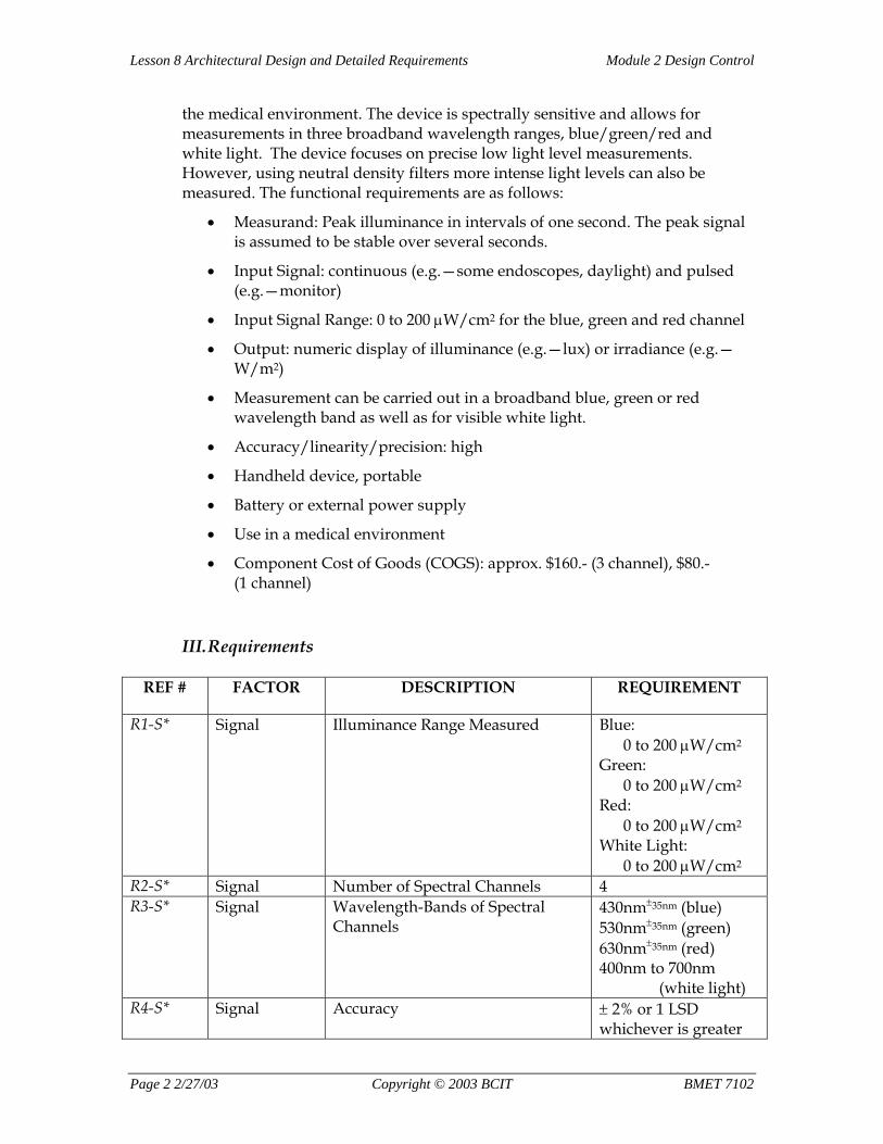
III. Requirements
REF # FACTOR DESCRIPTION REQUIREMENT
R1-S* Signal Illuminance Range Measured Blue: 0 to 200 µW/cm2
Green: 0 to 200 µW/cm2
Red: 0 to 200 µW/cm2
White Light: 0 to 200 µW/cm2
R2-S* Signal Number of Spectral Channels 4 R3-S* Signal Wavelength-Bands of Spectral
Channels 430nm±35nm (blue) 530nm±35nm (green) 630nm±35nm (red) 400nm to 700nm (white light)
R4-S* Signal Accuracy ± 2% or 1 LSD whichever is greater
Page 2 2/27/03 Copyright © 2003 BCIT BMET 7102
Module 2 Design Control Lesson 8 Architectural Design and Detailed Requirements
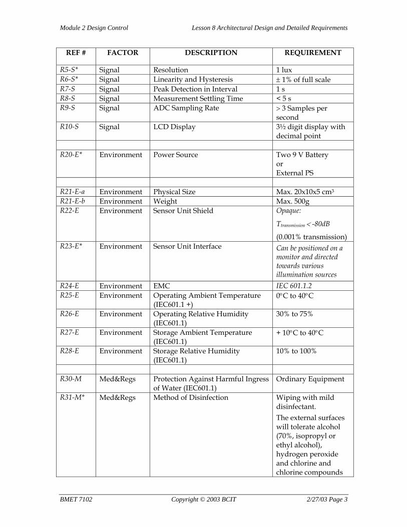
REF # FACTOR DESCRIPTION REQUIREMENT
R5-S* Signal Resolution 1 lux R6-S* Signal Linearity and Hysteresis ± 1% of full scale R7-S Signal Peak Detection in Interval 1 s R8-S Signal Measurement Settling Time < 5 s R9-S Signal ADC Sampling Rate > 3 Samples per
second R10-S Signal LCD Display 3½ digit display with
decimal point R20-E* Environment Power Source Two 9 V Battery
or External PS
R21-E-a Environment Physical Size Max. 20x10x5 cm3
R21-E-b Environment Weight Max. 500g R22-E Environment Sensor Unit Shield Opaque:
Ttransmission < -80dB
(0.001% transmission) R23-E* Environment Sensor Unit Interface Can be positioned on a
monitor and directed towards various illumination sources
R24-E Environment EMC IEC 601.1.2 R25-E Environment Operating Ambient Temperature
(IEC601.1 +) 0°C to 40°C
R26-E Environment Operating Relative Humidity (IEC601.1)
30% to 75%
R27-E Environment Storage Ambient Temperature (IEC601.1)
+ 10°C to 40°C
R28-E Environment Storage Relative Humidity (IEC601.1)
10% to 100%
R30-M Med&Regs Protection Against Harmful Ingress
of Water (IEC601.1) Ordinary Equipment
R31-M* Med&Regs Method of Disinfection Wiping with mild disinfectant. The external surfaces will tolerate alcohol (70%, isopropyl or ethyl alcohol), hydrogen peroxide and chlorine and chlorine compounds
BMET 7102 Copyright © 2003 BCIT 2/27/03 Page 3
Lesson 8 Architectural Design and Detailed Requirements Module 2 Design Control
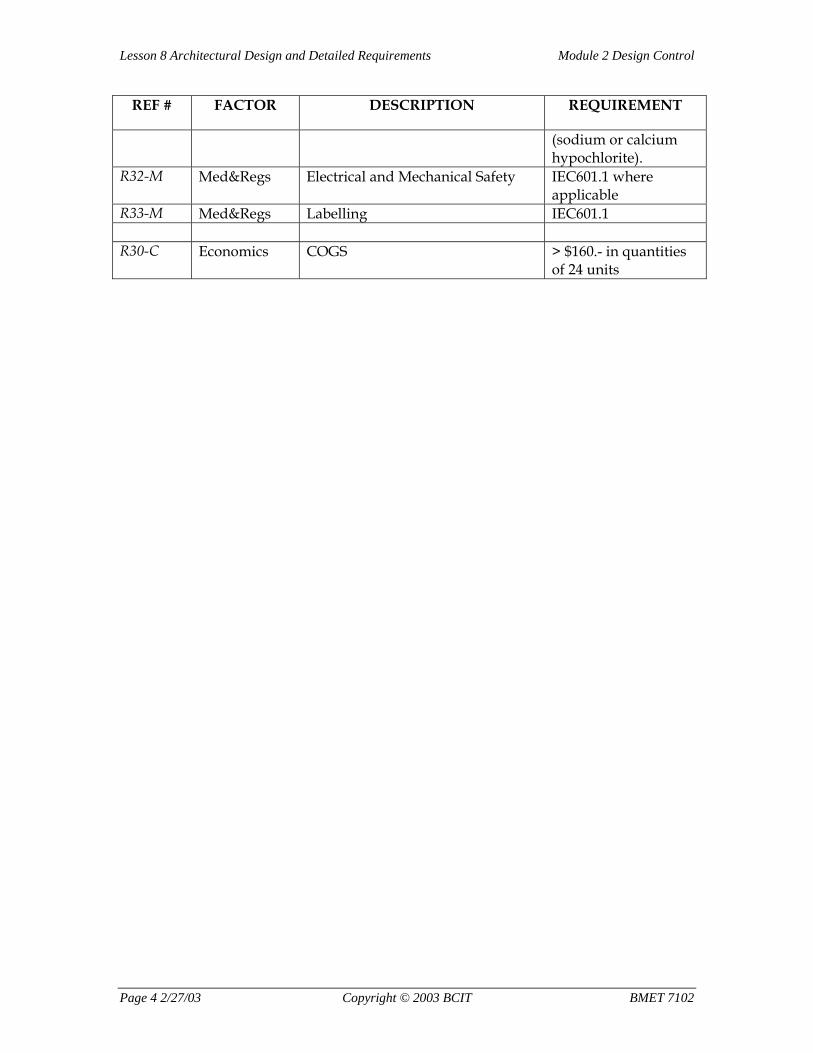
REF # FACTOR DESCRIPTION REQUIREMENT
(sodium or calcium hypochlorite).
R32-M Med&Regs Electrical and Mechanical Safety IEC601.1 where applicable
R33-M Med&Regs Labelling IEC601.1 R30-C Economics COGS > $160.- in quantities
of 24 units
Page 4 2/27/03 Copyright © 2003 BCIT BMET 7102
Module 2 Design Control Lesson 9 Implementation and Design Output
Assignment #9:
Guidance Document on Design Control
This is a self-study assignment. Do not hand in.
To assist medical device manufacturers in the understanding of the design control regulations (21CFR820.30), the FDA has published an excellent guidance document: “Design Control Guidance for Medical Device Manufacturers,” March 11th, 1997. This document can be found at the following URL, on the Internet:
http://www.fda.gov/cdrh
To reach the document once you are on the FDA Web site, click “Manuals and Publications,” then click “Center for Devices and Radiological Health,” then click “How to get information from CDRH,” and then click “Guidance Document.”
To reach the document once you are on the FDA-CDRH Web site do an online search of guidance documents.
Task Read the document. The purpose of this assignment is to review the material of this course relating to design control. Note that sections E to J of the guidance document are material that will be discussed in the following lessons. Reading those sections will give you a head start.
BMET 7102 Copyright © 2003 BCIT 2/27/03 Page 0
Module 2 Design Control Lesson 10 Verification and Validation
Assignment #10:
Verification and Validation Introduction To write a verification and validation document for medical devices is typically a complex task. The measurements and methods used to carry out the tests need to be fully defined in a test plan. Furthermore, each requirement needs to be addressed, and all essential functions need to be validated.
In order not to lose sight of the basic idea of verification and validation, a simple example of a measurement device (i.e. – a device to measure relative humidity and temperature) is used in this assignment. It is not the intent of this assignment to provide a complete verification or validation document, but rather to give the student a better appreciation of what a verification and validation document entails. Please note that Biomedical Engineering Technology students have actually built the device described below. To develop the device, the students applied methodologies consistent with design controls.
The key to writing a verification document is a clearly defined requirement specification document. Based on this document, quantitative measurements for each requirement can be defined. This includes a pass/fail criteria as well as the method used to carry out the measurement(s).
The key to writing a validation document is clearly defined user needs.
In this assignment, you are given the functional description and the requirements. Using those, you are asked to write particular verification and validation tests.
Tasks 1. Study the Functional Description, Requirements and Block Diagram of
the “HygroThermoMeter.”
2. Write a verification test for the requirement specification R22-E-a and R22-E-b.
3. Write a verification test for the requirement specification R31-M.
4. Write a verification test for the requirement specification R6-S.
5. How would you carry out the design validation of this device? Describe in a couple of paragraphs how, where and with what means you could carry out the validation.
BMET 7102 Copyright © 2003 BCIT 2/27/03 Page
Module 2 Design Control Lesson 10 Verification and Validation
6. What kind of design validation questions would have to be answered? Provide specific examples.
7. Hand in the verification test for R6, R22 and R31. Hand in tasks 5 and 6.
8. Once you have received feedback from the instructor together with a solution, compare the solution provided with yours.
Humidity – Temperature Sensor Measurement Device (HygroThermoMeter)
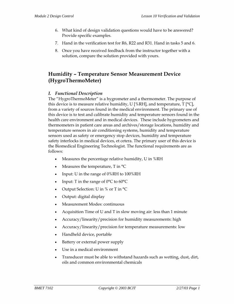
I. Functional Description The “HygroThermoMeter” is a hygrometer and a thermometer. The purpose of this device is to measure relative humidity, U [%RH], and temperature, T [°C], from a variety of sources found in the medical environment. The primary use of this device is to test and calibrate humidity and temperature sensors found in the health care environment and in medical devices. These include hygrometers and thermometers in patient care areas and archives/storage locations, humidity and temperature sensors in air conditioning systems, humidity and temperature sensors used as safety or emergency stop devices, humidity and temperature safety interlocks in medical devices, et cetera. The primary user of this device is the Biomedical Engineering Technologist. The functional requirements are as follows:
• Measures the percentage relative humidity, U in %RH
• Measures the temperature, T in °C
• Input: U in the range of 0%RH to 100%RH
• Input: T in the range of 0°C to 60°C
• Output Selection: U in % or T in °C
• Output: digital display
• Measurement Modes: continuous
• Acquisition Time of U and T in slow moving air: less than 1 minute
• Accuracy/linearity/precision for humidity measurements: high
• Accuracy/linearity/precision for temperature measurements: low
• Handheld device, portable
• Battery or external power supply
• Use in a medical environment
• Transducer must be able to withstand hazards such as wetting, dust, dirt, oils and common environmental chemicals
BMET 7102 Copyright © 2003 BCIT 2/27/03 Page 1
Lesson 10 Verification and Validation Module 2 Design Control
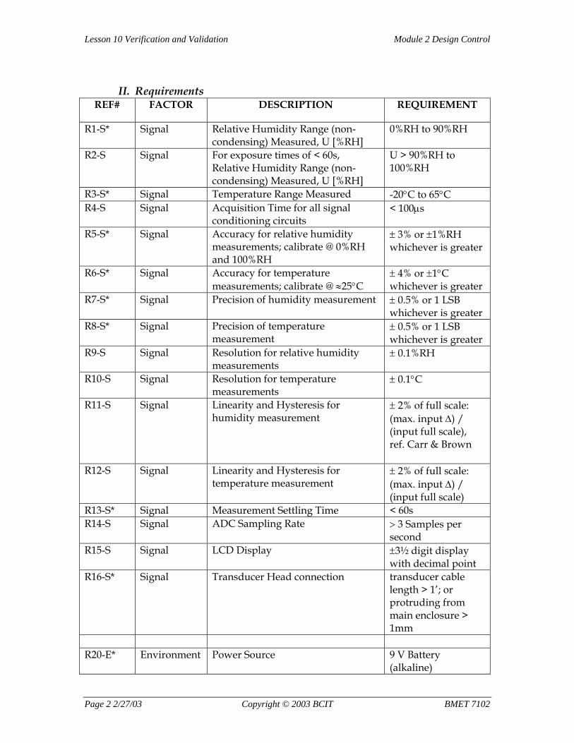
II. Requirements REF# FACTOR DESCRIPTION REQUIREMENT
R1-S* Signal Relative Humidity Range (non-condensing) Measured, U [%RH]
0%RH to 90%RH
R2-S Signal For exposure times of < 60s, Relative Humidity Range (non-condensing) Measured, U [%RH]
U > 90%RH to 100%RH
R3-S* Signal Temperature Range Measured -20°C to 65°C R4-S Signal Acquisition Time for all signal
conditioning circuits < 100µs
R5-S* Signal Accuracy for relative humidity measurements; calibrate @ 0%RH and 100%RH
± 3% or ±1%RH whichever is greater
R6-S* Signal Accuracy for temperature measurements; calibrate @ ≈25°C
± 4% or ±1°C whichever is greater
R7-S* Signal Precision of humidity measurement ± 0.5% or 1 LSB whichever is greater
R8-S* Signal Precision of temperature measurement
± 0.5% or 1 LSB whichever is greater
R9-S Signal Resolution for relative humidity measurements
± 0.1%RH
R10-S Signal Resolution for temperature measurements
± 0.1°C
R11-S Signal Linearity and Hysteresis for humidity measurement
± 2% of full scale: (max. input ∆) / (input full scale), ref. Carr & Brown
R12-S Signal Linearity and Hysteresis for temperature measurement
± 2% of full scale: (max. input ∆) / (input full scale)
R13-S* Signal Measurement Settling Time < 60s R14-S Signal ADC Sampling Rate > 3 Samples per
second R15-S Signal LCD Display ±3½ digit display
with decimal point R16-S* Signal Transducer Head connection transducer cable
length > 1’; or protruding from main enclosure > 1mm
R20-E* Environment Power Source 9 V Battery
(alkaline)
Page 2 2/27/03 Copyright © 2003 BCIT BMET 7102
Module 2 Design Control Lesson 10 Verification and Validation
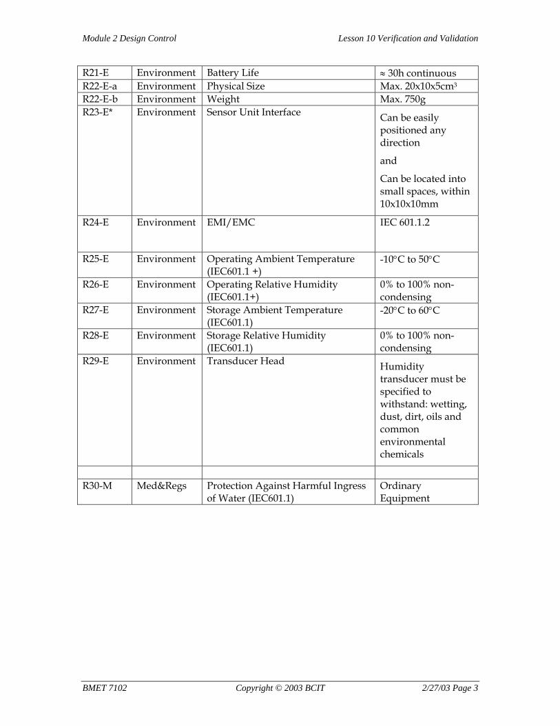
R21-E Environment Battery Life ≈ 30h continuous R22-E-a Environment Physical Size Max. 20x10x5cm3
R22-E-b Environment Weight Max. 750g R23-E* Environment Sensor Unit Interface Can be easily
positioned any direction
and
Can be located into small spaces, within 10x10x10mm
R24-E Environment EMI/EMC IEC 601.1.2
R25-E Environment Operating Ambient Temperature
(IEC601.1 +) -10°C to 50°C
R26-E Environment Operating Relative Humidity (IEC601.1+)
0% to 100% non-condensing
R27-E Environment Storage Ambient Temperature (IEC601.1)
-20°C to 60°C
R28-E Environment Storage Relative Humidity (IEC601.1)
0% to 100% non-condensing
R29-E Environment Transducer Head Humidity transducer must be specified to withstand: wetting, dust, dirt, oils and common environmental chemicals
R30-M Med&Regs Protection Against Harmful Ingress
of Water (IEC601.1) Ordinary Equipment
BMET 7102 Copyright © 2003 BCIT 2/27/03 Page 3
Lesson 10 Verification and Validation Module 2 Design Control
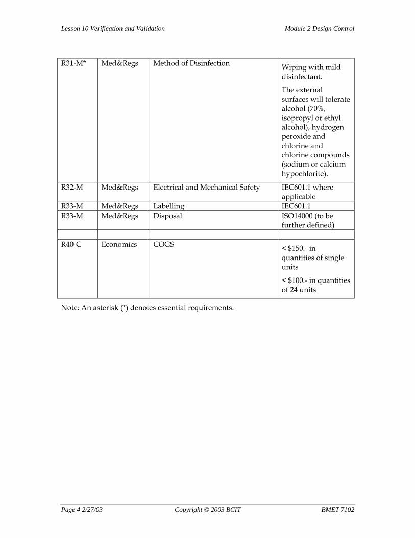
R31-M* Med&Regs Method of Disinfection Wiping with mild
disinfectant.
The external surfaces will tolerate alcohol (70%, isopropyl or ethyl alcohol), hydrogen peroxide and chlorine and chlorine compounds (sodium or calcium hypochlorite).
R32-M Med&Regs Electrical and Mechanical Safety IEC601.1 where applicable
R33-M Med&Regs Labelling IEC601.1 R33-M Med&Regs Disposal ISO14000 (to be
further defined) R40-C Economics COGS < $150.- in
quantities of single units
< $100.- in quantities of 24 units
Note: An asterisk (*) denotes essential requirements.
Page 4 2/27/03 Copyright © 2003 BCIT BMET 7102
Module 2 Design Control Lesson 10 Verification and Validation
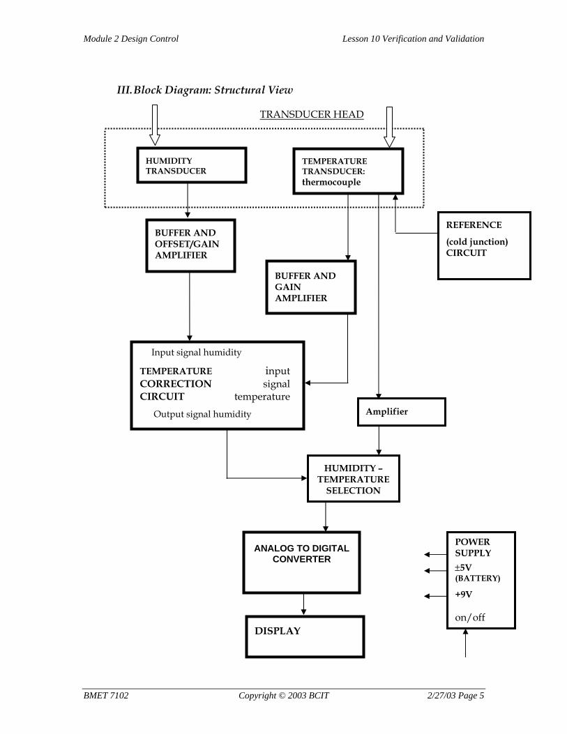
III. Block Diagram: Structural View
HUMIDITY TRANSDUCER
BUFFER AND OFFSET/GAIN AMPLIFIER
Input signal humidity
TEMPERATURE input CORRECTION signal CIRCUIT temperature Output signal humidity
REFERENCE
(cold junction) CIRCUIT
HUMIDITY – TEMPERATURE
SELECTION
Amplifier
ANALOG TO DIGITAL CONVERTER
DISPLAY
POWER SUPPLY ±5V (BATTERY)
+9V on/off
TEMPERATURE TRANSDUCER: thermocouple
BUFFER AND GAIN AMPLIFIER
TRANSDUCER HEAD
BMET 7102 Copyright © 2003 BCIT 2/27/03 Page 5
Module 3 Design Transfer and Post-design Activities Lesson 12 Design Documentation and Design Transfer
Assignment 12:
“The Seven Deadly Sins of Medical Device Development”
Introduction Read the enclosed article entitled, “The Seven Deadly Sins of Medical Device Development” by Brian Kelleher, originally published by MDDI, September 2001. In our experience, this essay addresses some of the key issues in successful medical device development. It is by no means a complete and detailed analysis of the issues, but it is a good start and summary. Without consulting the paper, answer the following questions, and compare your answers with the answers provided:
1. What are the seven deadly sins of medical device development according to Brian Kelleher?
2. What are the approximate estimates that a medical device development program, that has received funding, results in a marketable product?
3. What are essential criteria to start a project?
4. What are poorly defined specifications?
5. Before launching a project, extensive intellectual property searches must take place. Who should perform such searches?
6. What is the benefit of engaging a manufacturing engineer to evaluate critical cost targets and tolerance issues at the start of the project?
7. What specifically can be done in order to avoid or at least foresee poor financial return?
8. What elements are essential to provide strong project leadership?
9. Typically, a medical device development project consists of a series of investigations, analyses and decisions. Hence, the decision-making process is essential. How can such a process be strengthened?
10. Experience has shown that lead times are typically underestimated. Where have medical device manufacturers typically underestimated the lead times? Give examples.
BMET 7102 Copyright © 2003 BCIT 2/27/03 Page 0
Module 3 Design Transfer and Post-design Activities Lesson 12 Design Documentation and Design Transfer
11. What can be done during the development process in order to mitigate lead time problems?
12. What does the author mean by cautioning against “doing everything in parallel?”
13. What are some reasons that medical device companies tend to save the most difficult and riskiest engineering challenges until much later in the project?
14. What are the most common factors that lead to changes in requirements?
15. What is the preferable sequence of carrying out basic science tasks and development tasks? Can they be carried out in parallel?
16. What is the danger if the pre-clinical test results are unexpected, i.e. – disappointing or otherwise surprising?
17. During the evaluation and validation phase, marketing personnel are fully involved, and new requirements may come to light. This can have serious impact on the development. How can this be mitigated?
18. What are the most frequently ignored tasks in engineering-driven projects?
19. Brian Kelleher believes that most development pitfalls can be avoided by following what simple guidelines?
BMET 7102 Copyright © 2003 BCIT 2/27/03 Page 1
Lesson 12 Design Documentation and Design Transfer Module 3 Design Transfer and Post-design Activities
Assignment Reading (Reproduced with permission of Device & Diagnostic Industry of Canon Communications LLC)
Originally Published MDDI (http://www.devicelink.com/mddi/index.html) September 2001
The Seven Deadly Sins of Medical Device Development
When development efforts aren't well managed, appropriately documented, or realistically planned, a company's most innovative product ideas might never make it to market.
Brian Kelleher
By some estimates, less than one-third of medical device development programs that receive funding actually result in a marketable product. Of those that do, nearly all face at least one crisis along the way. A review of dozens of device development programs from the last two decades reveals seven types of problems that often contribute to project failure: launching products prematurely, failing to appoint satisfactory project leadership, misjudging lead times, trying to accomplish goals in parallel with each other, putting off challenges, straying from project requirements, and offering engineers uncontrolled freedom during the creative process. Even projects that are well managed, well funded, and well staffed may be susceptible to these problems. Fortunately, device companies can take steps to increase their chances of avoiding them.
1. Launching a Project too Soon Projects launched before the proposed product has been rigorously analyzed and evaluated begin their lives on a shaky foundation. As a result, resources and time can be lost when an insurmountable obstacle appears later on in the process. What follows are the most common flaws that device companies frequently overlook at the beginning of a project.
Poorly Defined Specifications. In an effort to launch a project without limiting their strategic options, companies sometimes begin with a vaguely written or overly broad set of product specifications. For instance, an orthopedics company enlisted the help of an electronics firm to develop a stimulator for incorporation into a certain type of brace. The stimulator was specified to produce a broad set of waveforms for pain control, muscle rehabilitation, and bone growth stimulation. Since these three stimulation therapies are vastly different not only from an electronics standpoint but also from a regulatory and user-interface perspective, the project's direction was never clear. The resulting product was expensive and its user interface was complicated. Consequently, it didn't succeed in the marketplace.
To avoid a situation like this one, marketing personnel must explicitly define customer needs, and scientists must quantify performance criteria more objectively. Equally as important, development teams need to make
Page 2 2/27/03 Copyright © 2003 BCIT BMET 7102
Module 3 Design Transfer and Post-design Activities Lesson 12 Design Documentation and Design Transfer
managers aware of specifications that remain unclear or that otherwise necessitate added effort or expense.
Insurmountable Technical Hurdles. Technical problems are frequently responsible for total project failure. For example, a CEO of an early-stage medical device company came up with an idea for treating a certain form of reflux disease with an implantable valve. The idea of a valve was attractive because of its simplicity and potential for healthy profit margins, but questions about long-term biocompatibility made the technology risky. Nevertheless, the company moved ahead with the development of the device, focusing its engineering efforts on the valve form and materials while sidestepping the challenges of the valve's installation and compatibility with surrounding tissue. After the company had devoted nine months and nearly a million dollars to the project, preliminary acute animal tests revealed the approach to be essentially unworkable because of the convulsive nature of the esophagus. Had the initial concept been carefully evaluated by qualified technical personnel, this endeavor might have been a success.
Intellectual Property Problems. Although intellectual property issues are likely to define the competitive landscape for medical device companies in the twenty-first century, a number of companies are still relying on cursory patent searches performed by their attorneys or their attorneys' agents. These types of searches generally turn up much of the relevant prior art, but it is not unusual for important existing patents to go undiscovered. As a result, years of development may need to be redirected once the intellectual property situation is completely revealed. To avoid such unpleasant surprises, development programs should involve a great deal of early interaction between the inventors, the development team, and the patent attorneys in order to devise and execute robust offensive and defensive intellectual property strategies.
Unacceptable Manufacturing Costs. Although most experienced managers know better than to leave manufacturing staff out of the development cycle, few have the luxury of engaging a manufacturing engineer to evaluate critical cost targets and tolerance issues at the start of a project, especially in small companies. Unfortunately, omitting this important step can cause far-reaching consequences. Take, for example, a flexible-endoscope start-up firm that developed a novel disposable sheathing system. The company launched the product with sheaths made using labor-intensive processes and short-run tooling, hoping to significantly reduce production costs by automating the manufacturing process once market demand had been established. Despite the company's eventual investment in hard tooling and automation, however, costs could never be reduced to a profitable level. A focused manufacturing analysis in the early stages of the company's project planning might have led to a business-saving course correction. For smaller companies like this one that lack a staff manufacturing engineer, outside vendors can be recruited to assist with an analysis.
Poor Financial Return. Many projects that face a crisis situation do so because of financial problems. Either development costs run out of control, or revenue falls short of expectations after market launch. Both of these unfortunate circumstances can catapult a company into financial crisis, especially in the case of start-up companies with a single product focus. In
BMET 7102 Copyright © 2003 BCIT 2/27/03 Page 3
Lesson 12 Design Documentation and Design Transfer Module 3 Design Transfer and Post-design Activities
these situations, any cost overruns or revenue shortfalls can lead to increased scrutiny from investors and board members, many of whom lack first-hand experience with the challenges of product development. The best way to thwart this risk is to build reasonable worst-case assumptions not only into cost projections but also into development timelines and revenue pro formas.
Assuming worst-case scenarios, however, is especially unappealing to start-up companies, because the resulting projected return on investment might look less attractive to investors. Fortunately, most experienced entrepreneurs have learned that it's much better to accept a lower valuation on the first round of capitalization than to risk launching a plan that's unachievable under real-world conditions.
2. Inadequate Project Leadership Viable projects are sometimes doomed from the start by a lack of effective project leadership. The following are some typical leadership errors made by project managers and by the companies that appoint them.
Following a Flawed Decision-Making Process. Most medical device development projects consist of a series of investigations, analyses, and decisions. Critical to the success of a project is a decision-making process that is defined at the start and remains consistent throughout the life of the project. Without a consistent and well-defined decision-making process, decisions tend to be made, reversed, and reversed again later in the project, often without any new information as justification. The most successful projects encourage a team-oriented decision-making process but provide for a single, strong leader as the ultimate decision maker. As an additional preventative measure, each decision should be documented in the design-history file—along with a brief rationale—so that if the issue comes up again, it can be quickly and definitively addressed.
Making Frequent Managerial Changes. Few things can undermine a program more profoundly than an ineffective manager. Proper mechanisms should be in place within a company to permit such a problem to be quickly recognized and remedied. Too often, however, companies overreact to poor leadership by changing managers too readily. When afflicted by this unfortunate manager-of-the-month syndrome, projects suffer from the inefficiencies of redefining development strategies and shuffling priorities and resources. As a result, project team members become disenchanted and productivity suffers.
In one recent extreme example of this phenomenon, an orthopedic start-up company appointed seven different managers during the first year of its principal development program before finally settling on a matrix-management structure with a strong central leader. Incredibly, the project survived.
Lacking the Authority to Get the Job Done. While charisma and strength of personality play significant roles in a manager's success, he or she must also possess the authority to request and elicit cooperation from each product development team member and to quickly marshal other in-house and
Page 4 2/27/03 Copyright © 2003 BCIT BMET 7102
Module 3 Design Transfer and Post-design Activities Lesson 12 Design Documentation and Design Transfer
outside resources as needs arise. Furthermore, an authoritative manager must be free to wield influence and break rules (within reason) in order to complete tasks on time. Such authority can only come from upper-level management, such as a CEO or vice president of R&D, and should be visibly granted at the project's inception and reinforced throughout its duration.
3. Underestimating Lead Times It may seem obvious, but the single most devastating mistake made in a time-critical medical device development program is to underestimate necessary lead times. Five examples of lead-time estimation errors—and their consequences—are presented below.
Lead Times for Ordinary Parts. Over the past several years, obtaining seemingly unremarkable components such as capacitors, logic integrated circuits, and even connectors has required lead times of up to a year. In particular, electronic components in heavy demand for use in cellular phones, such as tantalum capacitors, can be nearly impossible for medical device companies to find. Furthermore, because most medical device companies deal with relatively low volumes of products, these firms often find themselves at the end of the line when commodity components are in scarce supply. Accordingly, drawing up a preliminary bill of materials and fleshing out any lead-time issues early in a project is well worth the effort. Finally, early vendor involvement can help developers avoid potential supply problems.
Custom Part Fabrication. Underestimating the time it takes to have a custom component fabricated, whether that component is a molded plastic part or a custom integrated circuit, is a common cause of project delay. Project managers typically insert vendor-quoted lead times into their schedules, when, in reality, obtaining production-grade parts (especially those with unusual features such as tight tolerances or exotic materials) takes 50–100% longer than the vendors' estimates.
For example, a company developing tiny jaws for an endoscopic-biopsy tool chose metal injection molding as the fabrication method. The lead time quoted by the vendor was eight weeks, and the first batch of parts was delivered in about nine. Unfortunately, that batch didn't meet the company's tolerance goals. So, the parts underwent several subsequent design iterations and mold changes, which took an additional 16 weeks to complete.
Safety and EMC Testing. Relying on the standard lead-time quote from a compliance agency can create another problem. For sensitive electronic equipment, electromagnetic compatibility (EMC) testing can be expensive and may take several months longer than anticipated. The best ways to mitigate this risk are to enlist the help of experienced advisors during the initial design phase and to plan for periodic safety reviews and EMC prescans after each critical piece of the system is prototyped.
Product Validation. A carefully constructed project plan should include a healthy budget for verification and validation efforts throughout the life of the project. Even with such a budget, however, some potentially problematic issues must be kept in mind to avoid surprise delays. For example, sterile
BMET 7102 Copyright © 2003 BCIT 2/27/03 Page 5
Lesson 12 Design Documentation and Design Transfer Module 3 Design Transfer and Post-design Activities
disposable medical devices must undergo a sterilization validation procedure requiring a significant number of production-quality devices to be tested. Though the time required for testing is minimal, it's often an overlooked step that has to be sandwiched between pilot production and product release. For reusable medical devices, the requirements are much more demanding; often weeks or months of reprocessing and accelerated aging may be required to ensure that devices will maintain their reprocessing capabilities in the field.
Product Transfer. Misjudging the amount of time and effort needed to transfer a product from R&D to manufacturing is another common development pitfall. Tasks such as test-plan development, fixture design, and drafting of inspection procedures and work instructions rarely make their way into a project plan with adequate allocation of time and resources. As a result, project teams often face a few extra months of work after their products are supposedly "finished." To mitigate this risk, companies should encourage the involvement of manufacturing personnel and key vendors as early as possible in the development process.
4. Trying to Do Everything in Parallel In an effort to accelerate development programs, medical device companies have learned to devise project plans with multiple parallel pathways. This type of planning can get out of hand, however, when the plans encompass everything from basic research and animal testing to software validation and fixture design. Parallel planning is attractive on paper, but it often falls short of expectations in practice. The following problems present challenges to parallel-planning efforts.
Resource Overloading. Most Gantt chart users don't take full advantage of the capabilities of project management software. They typically plug in the task descriptions, dependencies, costs, and resource names, but that's all. The program displays task bars and costs and identifies critical paths, but it doesn't really pass judgment on the practicality of the plan. By contrast, if resources are accurately characterized, and if resources needed for the project are realistically estimated (resource levelled), the software will serve a more useful purpose. For example, it may reveal that either the company needs five times its existing engineers or the project schedule should be five times longer than planned. Managers sometimes turn a blind eye to resource levelling with the hope that their team members will work five times harder if they need to. Unfortunately, the result can be a chronically burnt-out, demoralized project team that's always behind schedule.
Unmanageable Interdependencies. When developing a simple product, such as a bone plate, it's relatively easy for a firm to execute several tasks in parallel because few individuals are involved and few variables exist in the development equation.
On the other hand, when developing a more complicated device, such as an electromedical system, keeping all the different tasks moving along on schedule and tracking the various dependencies poses a significantly more difficult challenge. Control is quickly lost when any significant change in one task affects others, resulting in a domino-like sequence of task adjustments
Page 6 2/27/03 Copyright © 2003 BCIT BMET 7102
Module 3 Design Transfer and Post-design Activities Lesson 12 Design Documentation and Design Transfer
and delays. This often leads to confusion, finger-pointing, and a general breakdown of teamwork.
Premature Filings. For many projects, the tasks of longest duration are those relating to regulatory approvals and patent applications. In an effort to keep these from holding up the rest of the project, there is a real temptation to file 510(k)s, premarket approval (PMA) applications, or patent applications early in the project. There is risk in doing so; for example, filing an incomplete 510(k) can result in an outright rejection by FDA during its initial screening of the application. Such a rejection can waste time and taint the company's reputation with the agency. On the other hand, if the submission passes the initial screen, the design team may be forced to live with the specifications, design architecture, and materials that were disclosed in the early submission—all of which may become obsolete as the project matures.
As for patent filings, submitting an early application (such as a provisional filing) may be a good idea if the technology or concept is well characterized, or if a general methods patent is desired. But designs often take many unexpected twists and turns as projects progress, deviating significantly from what may have been described in an earlier patent filing. Accordingly, early filings may be of little use in protecting later-stage developments.
5. Saving the Hardest Tasks for Last Often, medical device companies find themselves under significant pressure to show progress in a development project soon after it is launched. Because of this pressure, they sometimes put off dealing with the most difficult or riskiest engineering challenges until much later in the project.
The Trade Show Effect. Major trade shows and scientific conferences are prime venues for new product introductions, but their timing can sometimes lead to undue haste. Because marketing departments are often anxious to generate customer enthusiasm for a new product at such events, they may feel tempted to launch a product prematurely. In one case, a company developed a novel ambulatory pH-monitoring system and chose to launch it at a major conference in the fall, though quite a few significant design problems remained unsolved. To meet a pending trade show deadline, the engineering team stopped working on the more critical problems associated with the product to focus exclusively on making working models for the show. While the models were compelling enough to elicit purchasing interest from early adopters, the company needed an additional six months to work through the tough problems it had sidestepped. Consequently, interest in the product waned, and the company's relaunch at the next major conference the following spring was relatively lackluster.
Management by Milestones. Over the past decade, industry has seen a growing trend toward milestone-based funding by venture capital groups. These schemes are intended to align the interests of investors with those of entrepreneurs by granting incremental funds as certain predetermined milestones are met. Commonly cited milestones include "working prototype complete," "patent application filed," and "successful animal trials performed." Unfortunately, these circumstances can tempt a company to focus entirely on
BMET 7102 Copyright © 2003 BCIT 2/27/03 Page 7
Lesson 12 Design Documentation and Design Transfer Module 3 Design Transfer and Post-design Activities
achieving its milestones to qualify for each round of financing, thereby putting off the most difficult technical challenges for last. Take, for example, the start-up firm that was developing a novel eyeglass-lens manufacturing process. The company raised more than $6 million by completing milestones set by its investor group. These milestones included the development of engineering prototypes, the completion of a marketing plan, the establishment of an advisory board, the hiring of a sales force, and the construction of a manufacturing facility. Unfortunately, when the product went through its final validation, the underlying process was deemed inadequate to support the required accuracy and cost targets. In the end, the company folded.
Design First; Ask Questions Later. It is typical for early-stage companies to function in constant money-raising mode, with potential investors parading through their facilities to inspect the technology at any given time. In this type of atmosphere, it's unpopular for company insiders to raise any questions about the viability or marketability of the product or technology, for fear of scaring off investors. At the same time, however, project teams need to show significant continued progress, such as the development of working models or preclinical prototypes. As a result, the development effort may appear to progress smoothly on the surface while, underneath, there may be a growing unspoken anxiety about the underlying technology. Unless a major breakthrough occurs, product development stalls when the shortcomings of the technology surface and investor expectations clash with reality.
6. Changing Requirements A medical device development project can be compared to a chain of school kids playing crack the whip on a playground. In the early stages of development, when just a few people are involved, changes in requirements at the front of the chain yield limited influence on those at the end. But later in the project, when 10, 20, or 100 people are involved, small changes in requirements become amplified along the chain of tasks. The unlucky people at the end of the chain are whipped back and forth so hard that they can hardly hang on. As such, it's crucial to the success of a project and to all those involved to carefully develop a set of viable product requirements, and then to adhere to them as closely as possible throughout the project. Unfortunately, doing so isn't always practical, especially when projects are planned with many interdependent tasks happening at the same time. Some of the most common factors that lead to changes in requirements include the following.
Changes in Basic Science. Whenever basic science tasks are planned in parallel with development tasks, the potential for crisis is likely. Take, for example, a company that developed an iontophoretic, transdermal drug-delivery system. A preliminary analysis revealed the desired drug-transfer rate was possible based on certain assumptions about ionic current flow. In conjunction with experiments to confirm the drug-transfer rate, engineering efforts to design the control electronics and electrodes were set in motion. To the disappointment of those involved, the drug experiments revealed that the desired rate of transfer could only be achieved with costly changes in the carrier solution and the drive electronics. Consequently, the product
Page 8 2/27/03 Copyright © 2003 BCIT BMET 7102
Module 3 Design Transfer and Post-design Activities Lesson 12 Design Documentation and Design Transfer
requirements were significantly revised and most of the initial engineering efforts had to be scrapped.
Unexpected Preclinical Test Results. When devices are at last put to use on animal subjects or patients, test results are often disappointing or otherwise surprising. Inevitably, if the project survives in spite of such results, product requirements must be modified. Unless preclinical testing is performed before significant engineering has taken place, changing the requirements at this stage can have wide-ranging consequences.
New Market Information. As a product development project nears completion, control of the project often shifts from engineering to marketing. When this shift occurs, marketing personnel begin bringing models and prototypes into clinical environments for simulated-use evaluation. During this process of disclosure and evaluation, new customer preferences, logistical constraints, and competitive activities may be discovered. These types of market revelations can seriously impact product requirements and can frustrate members of the technical staff, who may rightfully question why such issues weren't uncovered at the beginning of the program. Therefore, early and intimate collaboration between engineers, marketing executives, and customers in an actual clinical environment is crucial to timely project success. After an initial specification is approved by the group, product improvement ideas should be logged in a separate section of the design-history file for incorporation into future versions of the product.
Revising the Company Vision. As if insurmountable technological hurdles and uncontrollable external events aren't challenging enough on their own, some companies further cripple themselves by periodically changing their fundamental corporate direction. This type of change is sometimes a direct consequence of the manager-of-the-month syndrome described earlier, or it can result from an indecisive CEO who is hesitant to pick a single direction and stick to it. One start-up company, for instance, changed its vision three times within its first year of operation. The ramifications of these vacillations are great: projects are started, refocused, and started again. In addition, highly qualified personnel may leave to pursue opportunities with more clearly defined projects and a better chance of bringing products to market quickly.
7. Giving Engineers Free Rein (and Cleaning Up Afterward) Creative technical people are rarely enamored of the rigors of disciplined project management and document control. Unfortunately, an uncontrolled development phase can result in nonconforming design history files and additional delays and expense on the back end of a project. The following items and tasks are most frequently ignored when the creative process runs unchecked and unsupervised.
Formal Requirements Documents. Neglecting to draft and release formal requirements documents prior to performing design tasks is a commonly taken shortcut. Engineers are often heard saying, "Design it first, then write the spec." To a certain extent, this order of events makes sense, though it violates all basic design control guidelines and leads to an unacceptable design history file. As a compromise, product development programs should
BMET 7102 Copyright © 2003 BCIT 2/27/03 Page 9
Lesson 12 Design Documentation and Design Transfer Module 3 Design Transfer and Post-design Activities
plan for a concept development phase in order to settle any design uncertainties and to lay the foundation for a stable requirements document.
Human Factors Analysis. Engineering-driven projects tend to de-emphasize the need for human factors analysis during a project's evolution. Not infrequently, an industrial designer is brought in late in a project, after many decisions affecting human factors and ergonomics have already been finalized.
Take, for instance, a company that developed an ear thermometer under the guidance of two male physicians. Though the thermometer worked well for them, its resemblance to a handgun made mothers and some nurses reluctant to point it at children's ears. As a result, the product failed. A few representative focus groups and more human factors analysis in the early stages of development might have identified this problem and could have saved the otherwise successful project from its fate.
Up-Front Risk and Failure Analysis. Another tendency of engineers is to put off formal risk analysis and failure modes and effects analysis until after a design is completed. Unfortunately, this belief may cause an engineering group to suffer through a redesign effort if significant unmitigated hazards are discovered at the end of the design phase. To conform with design control guidelines, a formal set of analyses should be conducted before design efforts begin. The analyses then function as a roadmap for the engineering team and help team members make critical decisions that affect safety and performance.
Adequate Verification. Failure to conduct timely verification steps or perform design reviews after each design phase not only violates design control guidelines, but also circumvents the check-and-balance benefits that are fundamental to any quality system. A well-planned project breaks up the overall design into manageable chunks, each with its own verification step and design review. Engineers familiar with this type of chunk-by-chunk process learn to recognize that it isn't so different from what they normally do to verify that each design piece actually works. Performing verification tests after each design phase simply formalizes the process and documents the results.
Quality and Manufacturing Involvement. Keeping the quality and manufacturing groups out of the development process seems to be a natural, albeit unfortunate, cultural tendency in most companies. This tendency not only breeds ill will between development and other departments, it can also create a serious delay in the product release schedule. For example, process steps that seem straightforward to the R&D group may actually require significant refinement and validation before they are ready for full-scale production. Furthermore, early quality and manufacturing input on manufacturability, testability, and reliability issues can shorten the transition time from R&D to manufacturing and ultimately result in a better, more profitable product.
Page 10 2/27/03 Copyright © 2003 BCIT BMET 7102
Module 3 Design Transfer and Post-design Activities Lesson 12 Design Documentation and Design Transfer
Conclusion Most development pitfalls can be avoided by following these simple guidelines:
• Select an experienced project leader, and empower him or her to succeed.
• Create a culture where tough questions are encouraged.
• Tackle the most difficult tasks first. Flesh out any technological, marketing, or manufacturing risks.
• Develop a stable set of specifications before beginning formal design efforts.
• Develop a project plan with realistic lead times and resource requirements.
• Build design control tasks into the project plan.
• Involve manufacturing and quality assurance in the project from the start.
By following these rules, developers can maintain control of their projects and improve their chances of success. The seven deadly sins of medical device development pose little danger to companies that begin development with a healthy dose of preliminary analysis, planning, intellectual honesty, teamwork, and discipline.
Copyright © 2001 Medical Device & Diagnostic Industry
BMET 7102 Copyright © 2003 BCIT 2/27/03 Page 11