Embed Size (px)
Citation preview
Operating InstructionsBetriebsanleitung
CTD9300
GB
D
Temperature Dry Well Calibrator
Temperatur-Blockkalibrator
Temperature Dry Well Calibrator CTD9300-165/650
Temperatur-Blockkalibrator CTD9300-165/650
90
37
92
6 0
7/2
01
5
GB
D
Temperature Dry Well Calibrator Page 1 - 66
Temperatur-Blockkalibrator Seite 69 - 133
90
37
92
6 0
7/2
01
5
3
Temperature Dry Well Calibrators CTD9300 Contents
WIKA Operating Instructions CTD9300 Rev. 1
GBContentsContents
Information!This symbol identifies information, instructions or useful hints.
Caution!General point of hazard! Please heed the operating instructions.
Danger!Hazard of personal injury through electric voltage.
Danger!Hazard of personal injury through high temperatures.
1. General Instructions 5
2. Device Description 9
3. Moduses and Functions 21
4. Operating the Calibrator 51
5. Technical Data 60
6. Appendix 64
90
37
92
6 0
7/2
01
5
4 WIKA Operating Instructions CTD9300 Rev. 1
GB
Temperature Dry Well Calibrators CTD9300 Preface
WIKA Alexander Wiegand SE & Co. KG Alexander-Wiegand-Straße 30D-63911 KlingenbergGermanyPhone no.: (+49) 93 72/132-0Fax no.: (+49) 93 72/[email protected]
Preface
Congratulations on buying a WIKA temperature dry well calibrator of the CTD9300 family. For the time being, this family of calibrators comprises two devices for the following temperature ranges:
CTD9300-165 from -30 °C to 165 °C
CTD9300-650 from 40 °C to 650 °C
Since the operation of the devices is identical, we have decided tocombine the operating instructions for the two devices.
The operating instructions are intended for skilled workers andsemi-skilled workers. Thoroughly read the associated instructionsprior to every work step and adhere to the sequence specified.
Read the "General Instructions" section especially attentively.Memorise the pictograms and their significance.
The device is designed for calibrating temperature switches,thermocouples, resistance thermometers and mechanicalthermometers. Please use them in compliance with their intendeduse.
If you encounter any problems or if you have any questions, pleaserevert to your supplier or directly to the manufacturer.
90
37
92
6 0
7/2
01
5
5WIKA Operating Instructions CTD9300 Rev. 1
Temperature Dry Well Calibrators CTD93001. General Instructions
GB1. General Instructions
1.1 Fundamental Safety Instructions
When performing any work on the device, always heed the nationalsafety instructions and accident prevention regulations as well asthe following safety instructions in the present operatinginstructions.
Through the power cable, the device is supplied with a voltagehazardous to people.
The faultless and safe operation of the device requires appropriatetransport, professional storage, setup, and use as intended as wellas cautious operation and servicing.
Applications other than those described in the present operatinginstructions is regarded to be improper use and must thus beexcluded.
If faults cannot be eliminated, the device must be shut downimmediately and protected against inadvertent startup.
Danger!Only the manufacturer is authorized to perform repairs.Manipulation and modifications of the device are illegal.
Before replacing the safety fuse, the device must be disconnectedfrom the mains voltage by pulling the power plug out of the mainssocket.
For other important safety instructions, please refer to theindividual sections of these operating instructions.
90
37
92
6 0
7/2
01
5
6
Temperature Dry Well Calibrators CTD93001. General Instructions
WIKA Operating Instructions CTD9300 Rev. 1
GB 1.2 Safety Instructions Relating to Operation of the Device
The temperature dry well calibrators of the CTD9300 series have been developed and manufactured in compliance with the state of the art. This applies to the accuracy of measurement, the mode of operation and the safe operation of the devices. To guarantee safe operation, however, the operator must behave in an expertly and safety-conscious manner.
Relevant instructions are included in this section. Warnings relatingespecially to individual functional sequences and tasks are alsoincluded in the respective sections of the present operatinginstructions. These warnings are identified by special symbols.
Caution:Use the calibrator exclusively in compliance with the descriptionsincluded in the present operating instructions. Failure to observethe safety instructions and operating instructions will impair theprotective measures provided.
Danger!Before touching the dry well or the adapting sleeve, check thecurrent dry well temperature since a heated device bears theimminent risk of burns.
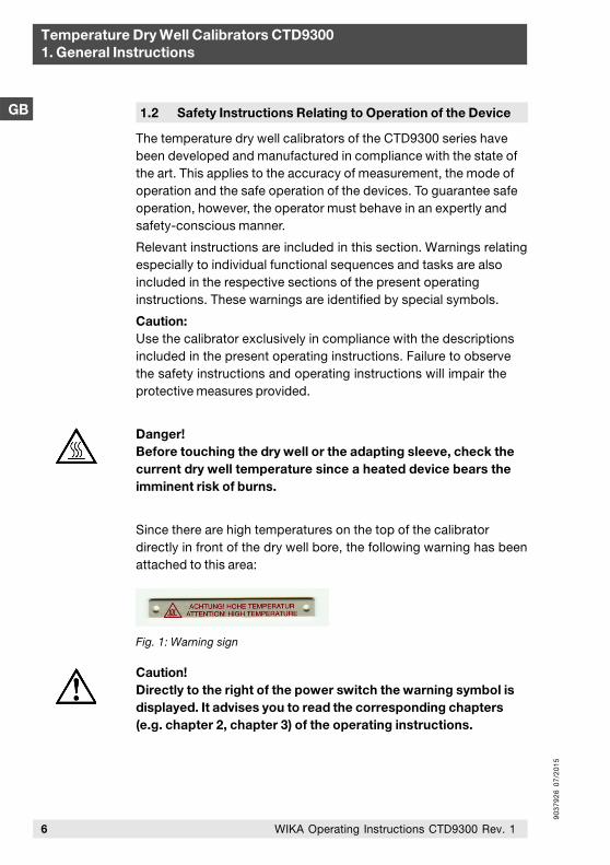
Since there are high temperatures on the top of the calibratordirectly in front of the dry well bore, the following warning has beenattached to this area:
Caution!Directly to the right of the power switch the warning symbol isdisplayed. It advises you to read the corresponding chapters(e.g. chapter 2, chapter 3) of the operating instructions.
Fig. 1: Warning sign
90
37
92
6 0
7/2
01
5
7WIKA Operating Instructions CTD9300 Rev. 1
Temperature Dry Well Calibrators CTD93001. General Instructions
GBSafety Instructions:
Remove all highly combustible media from the vicinity of thedevice and ensure that it cannot come into contact with easilyinflammable or explosive substances.
Make sure that the integrated fans can always deliver sufficientcooling air. Do not impair the air supply by placing the deviceson a soft, resilient surface.
Connect the devices to a power circuit with minimum risk of apower failure, since it will no longer be possible to supplycooling air in the case of a power failure
Make sure that the adapting sleeves and probes are notcontaminated with any substances (e.g. oil) that may causeignition or explosion during heating.
Never remove adapting sleeves from a heated dry well sinceheated adapter inserts bear a fire hazard.
Never remove probes from a heated dry well since these bear theimminent risk of burns.
Never leave a heated device unattended.
Always let a heated device cool to below 50 °C beforedisconnecting it from the mains.
Never try to repair the device yourself, always revert to themanufacturer.
Since the housing of the calibrator is made of metal, only powercables with ground wire may be used. Operate the calibratorexclusively with the power cable provided. The power cableconnector is on the bottom of the calibrator, i.e. when using adifferent type of cable, the calibrator may topple over.
If the calibrator is not used for an extended period of time, humiditymay penetrate into the heating element due to the material used.After transporting or storing the calibrator in a humid environment,the heating elements must thus be heated slowly when starting thecalibrator. During the drying process, the calibrator will not haveattained the isolation voltage required for protection class I.
The noise ramps of all dry well calibrators of the CTD9300 series are below 70 dbA.

90
37
92
6 0
7/2
01
5
8 WIKA Operating Instructions CTD9300 Rev. 1
Temperature Dry Well Calibrators CTD93001. General Instructions
GB
1.4 Duty to Take Due Care of the Operator
For safe operation of the device, the operator must especiallyensure that:
the device is exclusively used as intended (refer to the section"Intended Use" in chapter "Device Description") and that nohazardous media are used and all the technical specificationsare adhered to.
the device is operated in faultless, fully functional conditiononly.
the present operating instructions are always available in legiblecondition and complete at the application site of the device.
only authorised and qualified personnel operates, maintains andservices the device.
the operator of the device is periodically instructed in allapplicable operational safety and environmental protectionissues and that he/she is familiar with the operatinginstructions, especially with the safety instructions containedtherein.
1.3 Ground Wire Monitoring
For checking the basic isolation of the heater, the calibrator isequipped with a ground wire monitor. The monitoring unit operatesindependently of the other controller components and switches offthe power supply of the heater as soon as the calibrator loses theconnection to the ground wire system of the isolation. Once theconnection to the ground wire system has been re-established, themonitoring unit automatically reconnects the heating circuit to thepower system.
90
37
92
6 0
7/2
01
5
9WIKA Operating Instructions CTD9300 Rev. 1
2.2 Structure
Temperature dry well calibrators consist of an electrically heatedmetal block and a control unit. The two components areaccommodated in a robust metal housing together with a fan. Themetal block is fitted with a bore in its centre for holding theadapting sleeve. This adapting sleeve contains one or several boresof different diameters for thermically coupling thermometers ofvarious thicknesses optimally to the heated metal block. Goodthermal coupling between the block, the adapting sleeve and thethermometer is very important for keeping measuring uncertaintyduring calibration to a minimum.
Temperature Dry Well Calibrators CTD93002. Device Description
GB
2.1 Intended Use
2. Device Description
The calibrators of the CTD9300 series may be used exclusively for the calibration and verification of thermocouples, resistance thermometers, mechanical thermometers and temperature switches.
The introduction of foreign substances such as oil or heatconductive paste with the aim of enhancing the heat transfer to theprobe can damage the calibrator and the adapting sleeve.
In addition, there is a risk of injury due to abruptly evaporatingfluids and hazardous gases that may form when fluids evaporate.
Always ensure that the testing temperature is not too high for theprobe. Otherwise, the probe may be destroyed.
Remove all highly combustible media from the vicinity of thedevice and ensure that the device cannot come into contactwith easily inflammable or explosive media.
90
37
92
6 0
7/2
01
5
10 WIKA Operating Instructions CTD9300 Rev. 1
Temperature Dry Well Calibrators CTD93002. Device Description
GB Calibrators for Low Temperatures
If the calibrator generates temperatures lower than the ambienttemperature, it must be able to cool actively. In this case, theisothermal block is made of aluminium and is cooled and heatedthrough Peltier elements. Depending on the polarity of the voltage,the Peltier element will heat up on the top side while the oppositeside is cooled. One side of the element always makes contact to theisothermal block. The other side is connected to a cooling elementthat is cooled by a strong fan.
Through reversing the polarity and controlling the voltage at thePeltier elements, the block can be heated and cooled. For technicalreasons, the max. attainable temperature with Peltier elements islimited to approx. 165 °C. Depending on the model, the min.attainable temperature is -50 K to -60 K relative to the ambienttemperature.
Calibrators for High Temperatures
High-temperature calibrators for temperature ranges of from 40 °Cto 650 °C generally work with resistance heating elements.Depending on the upper limit temperature, different block materialsare used. Brass, bronze or scale-resistant steels.
Due to the low temperatures caused by the permanently decreasingcooling capacity of the air flow surrounding the block, the controlunit starts working sufficiently fast only at 20 K above therespective ambient temperature. This limits the lower workingtemperature of a device of this kind to approx. 40 °C.
The upper limit is defined through the block material used and thetemperature resistance of the heating elements used.
90
37
92
6 0
7/2
01
5
11WIKA Operating Instructions CTD9300 Rev. 1
Temperature Dry Well Calibrators CTD93002. Device Description
GB
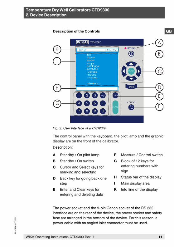
Fig. 2: User Interface of a CTD9300
The control panel with the keyboard, the pilot lamp and the graphicdisplay are on the front of the calibrator.
Description:
Description of the Controls
A Standby / On pilot lamp
B Standby / On switch
C Cursor and Select keys formarking and selecting
D Back key for going back onestep
E Enter and Clear keys forentering and deleting data
F Measure / Control switch
G Block of 12 keys forentering numbers withsign
H Status bar of the display
I Main display area
K Info line of the display
The power socket and the 9-pin Canon socket of the RS 232interface are on the rear of the device, the power socket and safetyfuse are arranged in the bottom of the device. For this reason, apower cable with an angled inlet connector must be used.
90
37
92
6 0
7/2
01
5
12 WIKA Operating Instructions CTD9300 Rev. 1
Temperature Dry Well Calibrators CTD93002. Device Description
GB
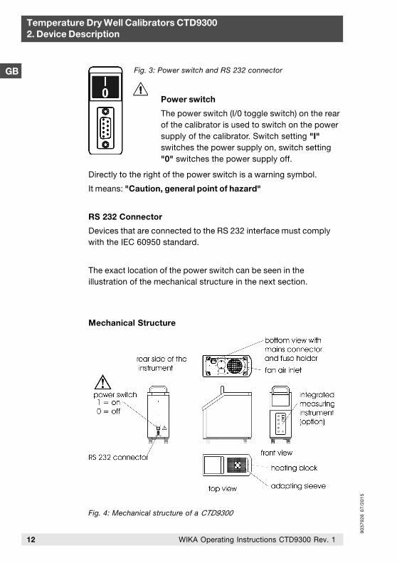
Power switch
The power switch (I/0 toggle switch) on the rearof the calibrator is used to switch on the powersupply of the calibrator. Switch setting "I"switches the power supply on, switch setting"0" switches the power supply off.
Fig. 3: Power switch and RS 232 connector
Directly to the right of the power switch is a warning symbol.
It means: "Caution, general point of hazard"
RS 232 Connector
Devices that are connected to the RS 232 interface must complywith the IEC 60950 standard.
The exact location of the power switch can be seen in theillustration of the mechanical structure in the next section.
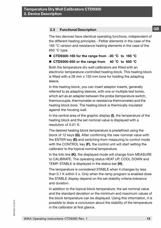
Mechanical Structure
Fig. 4: Mechanical structure of a CTD9300
90
37
92
6 0
7/2
01
5
13WIKA Operating Instructions CTD9300 Rev. 1
Temperature Dry Well Calibrators CTD93002. Device Description
GB2.3 Functional Description
The two devices have identical operating functions, independent ofthe different heating principles - Peltier elements in the case of the165 °C version and resistance heating elements in the case of the650 °C type.
CTD9300-165 for the range from -30 °C to 165 °C
CTD9300-650 or the range from 40 °C to 650 °C
Both the temperature dry well calibrators are fitted with anelectronic temperature-controlled heating block. This heating blockis fitted with a 28 mm x 150 mm bore for holding the adaptingsleeve.
In this heating block, you can insert adaptor inserts, generallyreferred to as adapting sleeves, with one or multiple test bores,which act as an adapter between the probe (temperature switch,thermocouple, thermometer or resistance thermometer) and theheating block bore. The heating block is thermically insulatedagainst the housing wall.
In the central area of the graphic display (I), the temperature of theheating block and the set nominal value is displayed with aresolution of 0.01 K.
The desired heating block temperature is predefined using theblock of 12 keys (G). After confirming the new nominal value withthe ENTER key (E) and switching from measuring to control modewith the CONTROL key (F), the control unit will start setting thecalibrator to the topical nominal temperature.
In the Info line (K), the displayed mode will change from MEASUREto CALIBRATE. The operating status HEAT UP, COOL DOWN andTEMP. STABLE is displayed in the status bar (H).
The temperature is considered STABLE when it changes by lessthan 0.1 K within 5 s. Only when the ramp program is enabled doesthe STABLE display depend on the set stability criteria toleranceand duration.
In addition to the topical block temperature, the set nominal valueand the standard deviation or the minimum and maximum values ofthe block temperature can be displayed. Using this information, it ispossible to draw a conclusion about the stability of the temperaturein the calibrator at first glance.
90
37
92
6 0
7/2
01
5
14 WIKA Operating Instructions CTD9300 Rev. 1
Temperature Dry Well Calibrators CTD93002. Device Description
GB
2.4 Standard Accessories
Power Cable
A power cable with a 90 ° angled inlet connector for the powersupply is included with every calibrator. Depending on the countrythe calibrator is delivered to, the power cable is fitted with thelocally used power plug.
Adapting Sleeve
Each calibrator is delivered ex works with an adapting sleeve withan inside diameter of 6.5 mm. Most of the industrial thermometerscan be adapted to the calibrator through this sleeve.
If the diameters of your thermometers differ, please order thedesired adapting sleeve with an internal bore matching the diameterof your thermometer plus 0.5 mm.
Sleeve Removal Tool
A sleeve removal tool for simple and easy removal from and insertion of the adapting sleeve into the calibrator block is included in the standard set of accessories of every temperature calibrator of the CTD9300 series.
Data Cable
A data cable for connecting the calibrator to the RS 232 interface isincluded in the scope of delivery of each device. The PIN layoutplan for 9-pin and 25-pin Sub-D connectors can be found in theAppendix, refer to section 6.6: PC Connection.
2.5 Special Accessories
The special accessories are not included in the standard scope ofdelivery.
Standard deviations as well as the min. and max. values can bereset at any time by pressing the ENTER (E) key.
90
37
92
6 0
7/2
01
5
15WIKA Operating Instructions CTD9300 Rev. 1
Temperature Dry Well Calibrators CTD93002. Device Description
GB2.5.1 Special Adapting Sleeves
Sleeves for CTD9300-165 calibrators are made of aluminium, sleeves for CTD9300-650 calibrators are made of brass. The outside dimensions of the two sleeves are Ø 28 mm x 150 mm of length.
Special adapting sleeves can be customized in various designs.Sleeves with multiple bores are also available. Limits are placedonly by the mechanical machinability of the sleeve blanks.
When choosing the sleeve design, however, please observe that theoverall measurement uncertainty declines with an increasingnumber of bore holes and with increasing bore diameter.
The actual measuring uncertainty when using a special adaptingsleeve can be determined only when the bore diameter and thenumber of bores as well as the design and material of thethermometers to be calibrated is exactly known.
If you require multiple sleeves, please take the following intoconsideration:
if possible, the bores should be arranged on a pitch circle toensure uniform temperature distribution.
for product engineering reasons, there must be a minimumdistance between the bores and to the edge of the sleeve. As arule, this distance should not be less than 2 mm.
the bore diameter should be larger than the thermometer to betested by at least 7 %.
2.5.2 Transport Case
As an option, we offer a robust transport case for your calibrator.We recommend the use of a transport case, if you frequently usethe device for on-site calibrations and thus need to transport itoften.
The case does not only protect your calibrator against environ-mental influences such as dust, dirt and humidity but also againstmechanical damage that may occur due to impacts and vibrations.
90
37
92
6 0
7/2
01
5
16 WIKA Operating Instructions CTD9300 Rev. 1
Temperature Dry Well Calibrators CTD93002. Device Description
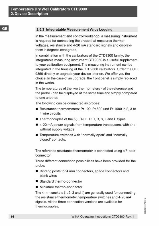
GB 2.5.3 Integratable Measurement Value Logging
In the measurement and control workshop, a measuring instrumentis required for connecting the probe that measures thermo-voltages, resistance and 4-20 mA standard signals and displaysthem in degrees centigrade.
In combination with the calibrators of the CTD9300 family, the integratable measuring instrument CTI 9350 is a useful supplement to your calibration equipment. The measuring instrument can be integrated in the housing of the CTD9300 calibrators. Order the CTI 9350 directly or upgrade your device later on. We offer you the choice. In the case of an upgrade, the front panel is simply replaced in the works.
The temperatures of the two thermometers - of the reference andthe probe - can be displayed at the same time and simply comparedto one another.
The following can be connected as probes:
Resistance thermometers: Pt 100, Pt 500 und Pt 1000 in 2, 3 or4 wire circuits
Thermocouples of the K, J, N, E, R, T, B, S, L and U types
4-20 mA power signals from temperature transducers, with andwithout supply voltage
Temperature switches with "normally open" and "normallyclosed" contacts.
The reference resistance thermometer is connected using a 7-poleconnector.
Three different connection possibilities have been provided for theprobe:
Binding posts for 4 mm connectors, spade connectors andblank wires
Standard thermo-connector
Miniature thermo-connector
The 4 mm sockets (1, 2, 3 and 4) are generally used for connectingthe resistance thermometer, temperature switches and 4-20 mAsignals. All the three connection versions are available forthermocouples.
90
37
92
6 0
7/2
01
5
17WIKA Operating Instructions CTD9300 Rev. 1
Temperature Dry Well Calibrators CTD93002. Device Description
GBAll the thermometer signals are linearised according to their signaltype and displayed in °C, °F or in K.
The sensor type, input and switch technology are set in the menufor measuring instrument setup.
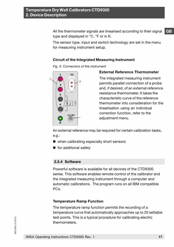
Circuit of the Integrated Measuring Instrument
External Reference Thermometer
The integrated measuring instrumentpermits parallel connection of a probeand, if desired, of an external referenceresistance thermometer. It takes thecharacteristic curve of the referencethermometer into consideration for thelinearisation using an individualcorrection function, refer to theadjustment menu.
An external reference may be required for certain calibration tasks,e.g.:
when calibrating especially short sensors
for additional safety
Fig. 5: Connectors of the instrument
2.5.4 Software
Powerful software is available for all devices of the CTD9300 series. This software enables remote control of the calibrator and the integrated measuring instrument through a computer and automatic calibrations. The program runs on all IBM compatible PCs.
Temperature Ramp Function
The temperature ramp function permits the recording of atemperature curve that automatically approaches up to 20 settabletest points. This is a typical procedure for calibrating electricthermometers.
90
37
92
6 0
7/2
01
5
18 WIKA Operating Instructions CTD9300 Rev. 1
Temperature Dry Well Calibrators CTD93002. Device Description
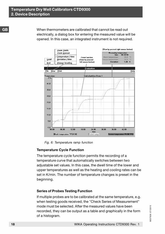
GB When thermometers are calibrated that cannot be read outelectrically, a dialog box for entering the measured value will beopened. In this case, an integrated instrument is not required.
Temperature Cycle Function
The temperature cycle function permits the recording of atemperature curve that automatically switches between twoadjustable set values. In this case, the dwell time of the lower andupper temperatures as well as the heating and cooling rates can beset in K/min. The number of temperature changes is preset in thebeginning.
Series of Probes Testing Function
If multiple probes are to be calibrated at the same temperature, e.g.when testing goods received, the "Check Series of Measurement"mode must be selected. After the measured values have beenrecorded, they can be output as a table and graphically in the formof a histogram.
Fig. 6: Temperature ramp function
90
37
92
6 0
7/2
01
5
19WIKA Operating Instructions CTD9300 Rev. 1
Temperature Dry Well Calibrators CTD93002. Device Description
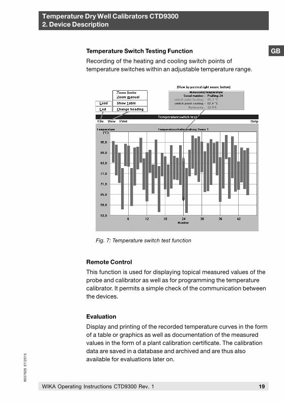
GBTemperature Switch Testing Function
Recording of the heating and cooling switch points oftemperature switches within an adjustable temperature range.
Remote Control
This function is used for displaying topical measured values of theprobe and calibrator as well as for programming the temperaturecalibrator. It permits a simple check of the communication betweenthe devices.
Evaluation
Display and printing of the recorded temperature curves in the formof a table or graphics as well as documentation of the measuredvalues in the form of a plant calibration certificate. The calibrationdata are saved in a database and archived and are thus alsoavailable for evaluations later on.
Fig. 7: Temperature switch test function
90
37
92
6 0
7/2
01
5
20 WIKA Operating Instructions CTD9300 Rev. 1
Temperature Dry Well Calibrators CTD93002. Device Description
DGB
2.5.5 DKD Calibration Certificate
The DKD calibration certificate gives the user the certainty that thecalibration results are based on national standards and the errors ofmeasurement do not exceed the error limits specified.
DKD calibrations are optionally available for all temperaturecalibrators. They are an option, the price of which depends on thenumber of test points required. For temperature dry well calibrators,DKD calibrations are generally performed at 6 test temperatures.The measuring uncertainty specified in the DKD calibrationcertificate depends on the device and temperature.
Calibration is a matter of trust. For this reason, entrust only ourcompetent DKD calibration workshop that has been certified incompliance with the applicable standard (currently DIN EN ISO/IEC17025) with the calibration of your valuable devices.
DKD laboratories are subject to periodical inspections by the PTB(Physikalisch-Technische Bundesanstalt = the German Nationallaboratory). The laboratory employees are permanently trained andeducated further. Regular inter laboratory comparisons prove thatthe minimum measuring uncertainty are really adhered to.
System Requirements
IBM-compatible PC with min. 486 processor with Windows 95, 98,NT 4.0, 9x, ME, 2000 and XP operating system and a main memoryof at least 64 MB, CD-ROM drive or 3 ½" FDD 1,44 MB, VGAgraphics board and monitor, free RS 232 serial interface andMicrosoft-compatible mouse.

90
37
92
6 0
7/2
01
5
21WIKA Operating Instructions CTD9300 Rev. 1
Temperature Dry Well Calibrators CTD93003. Moduses and Functions
GB
After switching on the calibrator, an information window will bedisplayed for approx. 5 s. Then the device switches to measuringmode. The current block temperature is displayed. The control unitis switched off.
In the following, the menu structure is displayed in simplified form.
The menu items for datalogger, RTD, TC and mA tests as well asswitch tests are accessible only, if a measuring instrument isintegrated, otherwise they will be hidden.
The two operating modes for measuring and calibrating and thefunctions of the Setup menu are described in the following.
3. Moduses and Functions
Fig. 8: Menu structure of a CTD9300
90
37
92
6 0
7/2
01
5
GB
Temperature Dry Well Calibrators CTD93003. Moduses and Functions
22 WIKA Operating Instructions CTD9300 Rev. 1
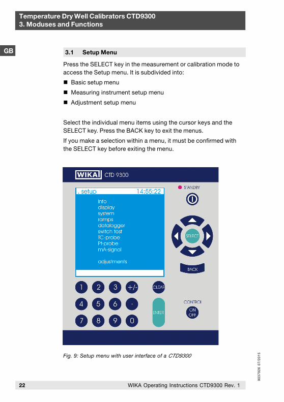
3.1 Setup Menu
Press the SELECT key in the measurement or calibration mode toaccess the Setup menu. It is subdivided into:
Basic setup menu
Measuring instrument setup menu
Adjustment setup menu
Select the individual menu items using the cursor keys and theSELECT key. Press the BACK key to exit the menus.
If you make a selection within a menu, it must be confirmed withthe SELECT key before exiting the menu.
Fig. 9: Setup menu with user interface of a CTD9300
90
37
92
6 0
7/2
01
5
GB
Temperature Dry Well Calibrators CTD93003. Moduses and Functions
23WIKA Operating Instructions CTD9300 Rev. 1
The basic setup menu is used for typical settings relating to thegeneral operation of the device, e.g. for calling the Info window thatprovides information on the current hardware and firmwareversions or enables editing of the system and display parameters.
The step menu, e.g. can be used to create temperature profiles andapproach them cyclically.
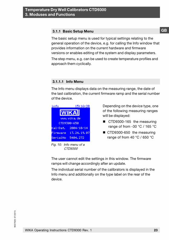
3.1.1.1 Info Menu
The Info menu displays data on the measuring range, the date ofthe last calibration, the current firmware ramp and the serial numberof the device.
Fig. 10: Info menu of aCTD9300
3.1.1 Basic Setup Menu
Depending on the device type, oneof the following measuring rangeswill be displayed:
CTD9300-165 the measuring range of from -30 °C / 165 °C
CTD9300-650 the measuring range of from 40 °C / 650 °C
The user cannot edit the settings in this window. The firmwareramps will change accordingly after an update.
The individual serial number of the calibrators is displayed in theInfo menu and additionally on the type label on the rear of thedevice.
90
37
92
6 0
7/2
01
5
Temperature Dry Well Calibrators CTD93003. Moduses and Functions
GB
24 WIKA Operating Instructions CTD9300 Rev. 1
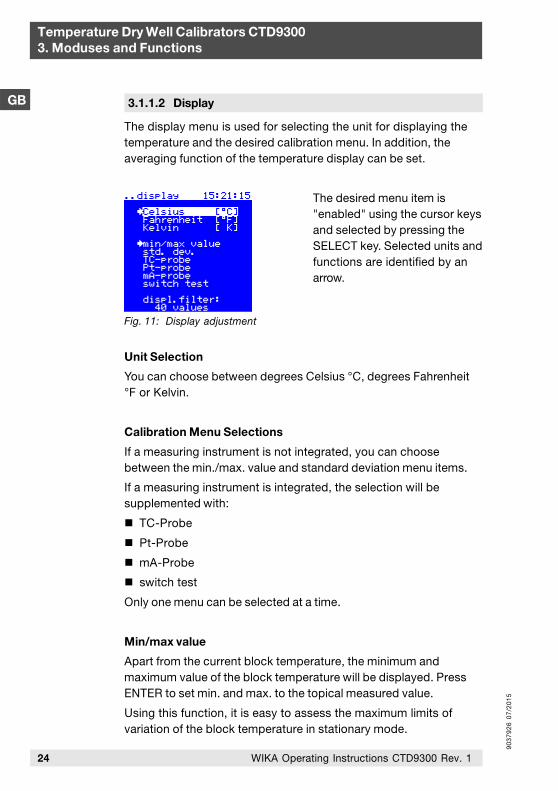
3.1.1.2 Display
The display menu is used for selecting the unit for displaying thetemperature and the desired calibration menu. In addition, theaveraging function of the temperature display can be set.
The desired menu item is"enabled" using the cursor keysand selected by pressing theSELECT key. Selected units andfunctions are identified by anarrow.
Unit Selection
You can choose between degrees Celsius °C, degrees Fahrenheit°F or Kelvin.
Calibration Menu Selections
If a measuring instrument is not integrated, you can choosebetween the min./max. value and standard deviation menu items.
If a measuring instrument is integrated, the selection will besupplemented with:
TC-Probe
Pt-Probe
mA-Probe
switch test
Only one menu can be selected at a time.
Min/max value
Apart from the current block temperature, the minimum andmaximum value of the block temperature will be displayed. PressENTER to set min. and max. to the topical measured value.
Using this function, it is easy to assess the maximum limits ofvariation of the block temperature in stationary mode.
Fig. 11: Display adjustment
90
37
92
6 0
7/2
01
5
Temperature Dry Well Calibrators CTD93003. Moduses and Functions
GB
25WIKA Operating Instructions CTD9300 Rev. 1
Standard Deviation
Instead of the min./max. value, the standard deviation is displayedhere, i.e. the mean quadratical error of the block temperature acrossthe last n measured values. After pressing ENTER, n = 0 is set andthe standard deviation will be recalculated.
Switch Test
Test menu for temperature switches, refer tosection 3.1.2 Measuring Instrument Setup Menu.
TC-Probe Menu
Calibration menu for thermocouples, refer tosection 3.1.2 Measuring Instrument Setup Menu.
Pt-Probe Menu
Calibration menu for resistance thermometers, refer tosection 3.1.2 Measuring Instrument Setup Menu.
mA-Probe Menu
Calibration menu for thermometers with temperature transducers,refer to section 3.1.2 Measuring Instrument Setup Menu.
Display Averaging
The actual value of the block temperature displayed by the devicecan correspond to the current temperature or be an average across2 to 99 measured values. The average is continuously calculatedfrom the last n measured values according to the FIFO method. Ameasuring rate of approx. 4 values/s, the following settings resultfor the number of average values:
1, averaging disabled
40, averaging for 10 s
99, averaging for 25 s
To ensure a steady display, we recommend averaging across 50measured values, which corresponds to an integration time of 13 s.
90
37
92
6 0
7/2
01
5
Temperature Dry Well Calibrators CTD93003. Moduses and Functions
GB
26 WIKA Operating Instructions CTD9300 Rev. 1
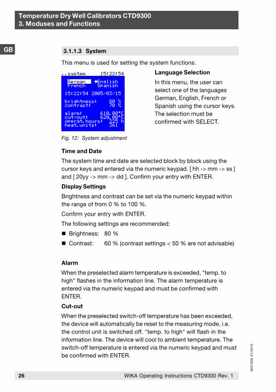
3.1.1.3 System
This menu is used for setting the system functions.
Language Selection
In this menu, the user canselect one of the languagesGerman, English, French orSpanish using the cursor keys.The selection must beconfirmed with SELECT.
Time and Date
The system time and date are selected block by block using thecursor keys and entered via the numeric keypad. [ hh -> mm -> ss ]and [ 20yy -> mm -> dd ]. Confirm your entry with ENTER.
Display Settings
Brightness and contrast can be set via the numeric keypad withinthe range of from 0 % to 100 %.
Confirm your entry with ENTER.
The following settings are recommended:
Brightness: 80 %
Contrast: 60 % (contrast settings < 50 % are not advisable)
Alarm
When the preselected alarm temperature is exceeded, "temp. tohigh" flashes in the information line. The alarm temperature isentered via the numeric keypad and must be confirmed withENTER.
Cut-out
When the preselected switch-off temperature has been exceeded,the device will automatically be reset to the measuring mode, i.e.the control unit is switched off. "temp. to high" will flash in theinformation line. The device will cool to ambient temperature. Theswitch-off temperature is entered via the numeric keypad and mustbe confirmed with ENTER.
Fig. 12: System adjustment
90
37
92
6 0
7/2
01
5
GB
27WIKA Operating Instructions CTD9300 Rev. 1
Temperature Dry Well Calibrators CTD93003. Moduses and Functions
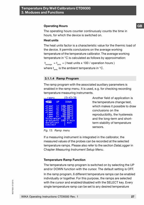
3.1.1.4 Ramp Program
The ramp program with the associated auxiliary parameters isenabled in the ramp menu. It is used, e.g. for checking recordingtemperature measuring instruments.
Another field of application isthe temperature change test,which makes it possible to drawconclusions on thereproducibility, the hysteresisand the long-term and short-term stability of temperaturesensors.
If a measuring instrument is integrated in the calibrator, themeasured values of the probes can be recorded at the selectedtemperature ramps. Please also refer to the section DataLogger inChapter Measuring Instrument Setup Menu.
Temperature Ramp Function
The temperature ramp program is switched on by selecting the UPand/or DOWN function with the cursor. The default setting is OFF.
In the ramp program, 6 different temperature ramps can be enabledindividually or together. For this purpose, the ramps are selectedwith the cursor and enabled/disabled with the SELECT key. Everysingle temperature ramp can be set to any desired temperature
Fig. 13: Ramp menu
Operating Hours
The operating hours counter continuously counts the time inhours, for which the device is switched on.
Heat units
The heat units factor is a characteristic value for the thermic load ofthe device. It permits conclusions on the average workingtemperature of the temperature calibrator. The average workingtemperature in °C is calculated as follows by approximation:
taverage = tamb. + ( heat units x 100 / operation hours )
where tamb. is the ambient temperature in °C.
90
37
92
6 0
7/2
01
5
Temperature Dry Well Calibrators CTD93003. Moduses and Functions
GB
28 WIKA Operating Instructions CTD9300 Rev. 1
within the operating range of the calibrator.The resolution is 0.01 K.
The individual temperature ramps are serially numbered from 1 to 6.If the "UP" function is enabled, the ramps are approached in theorder 1, 2, 3, 4, 5 and 6. If the "DOWN" function is enabled, theramps are approached in the order 6, 5, 4, 3, 2 and 1. If bothfunctions are enabled, the ramps are approached in the order 1, 2,3, 4, 5, 6, 5, 4, 3, 2 and 1. Disabled ramps are skipped.
Gradient
Using the gradient function, defined heating and cooling of thecalibrator can be set. The value for the gradient is set in K/min witha resolution of 1 K.
The upper ramp for the gradient is determined through the heatingpower of the respective device. This means that the device with thegradient function enabled cannot heat at a faster rate than with thegradient function disabled. The gradient function is primarily usedfor checking temperature switches. To prevent the switch point of atemperature switch from being exceeded during heat-up, thecalibrator is heated only slowly. Gradients between 1 K/min and5 K/min are typical. Especially for temperature switches with largeimmersion tube diameters, this prevents that the temperature of theswitch lags behind that of the calibrator.
Tolerance and Duration
Using the Tolerance and Duration functions, the stability andlength of the dwell time on a temperature ramp can be set. If thedwell time is to be 5 minutes with a stability of ±0.1 K after thenominal temperature has been reached, the duration must be set to5 min and the tolerance to 0.1 K. In this case, the timer will startwhen the actual temperature differs by less than 0.1 K from thenominal temperature. If the temperature remains within thistolerance for 5 min, the time period for the next ramp will beapproached after the present time period has elapsed. Iffluctuations occur during this time that exceed the set tolerance,the timer is reset and restarted. When the tolerance has beenreached, TEMP. STABLE is displayed in the status bar.
90
37
92
6 0
7/2
01
5
GB
Temperature Dry Well Calibrators CTD93003. Moduses and Functions
29WIKA Operating Instructions CTD9300 Rev. 1
3.1.2 Measuring Instrument Setup Menu
The measuring instrument setup menu is available only if thecalibrator is equipped with an integrated measuring instrument.The menu is used for configuring the data logger and thecalibration processes of temperature switches, thermocouples,resistance thermometers and 4-20 mA temperature transmitters.The menu is hidden if the calibrator is not equipped with anintegrated measuring instrument.
The integrated measuring instrument makes it possible to measurevarious sensor signals and to convert them to degrees Centigradeaccording to standardised characteristic curves. It is also possibleto detect switch points of temperature switches. The data loggingfunction permits storing as many as six probe temperatures and thenominal temperature per probe given by the calibrator. In total, thecalibration data of up to eight probes can be recorded.
The tolerance can be set within the limits of 0.01 K and 5.00 K,the duration within the range of from 1 min to 100 min.
Cycles
Using the Cycles function, the calibrator can approach the rampscontinuously. If e.g. the temperature ramps 1, 2 and 3 are enabledand the "UP" function has been selected, the ramps 1, 2 and 3 areapproached one after the other depending on the set cycles: with anumber of cycles of 3 this would be 1, 2, 3, 1, 2, 3, 1, 2 and 3.
If the "UP" and "DOWN" functions have been selected, thecalibrator will proceed as follows: 1, 2, 3, 2, 1, 2, 3, 2, 1, 2, 3, 2and 1.
This function is especially useful for temperature change tests ontemperature sensors.
If the ramp program is enabled, set-values cannot be enteredvia the keyboard. The keyboard will remain locked until thetemperature ramp function is disabled.

90
37
92
6 0
7/2
01
5
Temperature Dry Well Calibrators CTD93003. Moduses and Functions
GB
30 WIKA Operating Instructions CTD9300 Rev. 1
The following devices are supported:
Pt resistance thermometers with characteristic curves incompliance with EN 60751
Thermocouples in compliance with EN 60584 and DIN 43710
2-wire temperature transducer with an output signal of4-20 mA
Temperature switches with "normally closed" or "normally open"contacts.
3.1.2.1 Data Logger
This menu is used for configuring the data logger. The data loggerpermits the storage of calibration results of up to eight calibrations.In this case, a calibration can include up to six testingtemperatures. A prerequisite is that the ramp program is enabledand the desired testing temperatures have been set in advance inthis program.
The last cycle is always stored,independent of whether thelevels were approached frombottom to top or vice versa. Forthis reason, it is best to set thenumber of cycles to 1 whenrecording measured values.
When the data logger is disabled, sets, i.e. the measured valuestorages can be selected via the cursor keys. It is possible to selectSet1 to Set8.
One set may hold up to 6 measuring results. If e.g. only fourmeasurements are made, the remaining two rows of the value tableremain empty.
When the data logger is switched on, the measuring results arestored in the current set. It is not possible to change the set whenthe data logger is enabled.
Fig. 14: "Data Logger"setup menu
90
37
92
6 0
7/2
01
5
Temperature Dry Well Calibrators CTD93003. Moduses and Functions
GB
31WIKA Operating Instructions CTD9300 Rev. 1
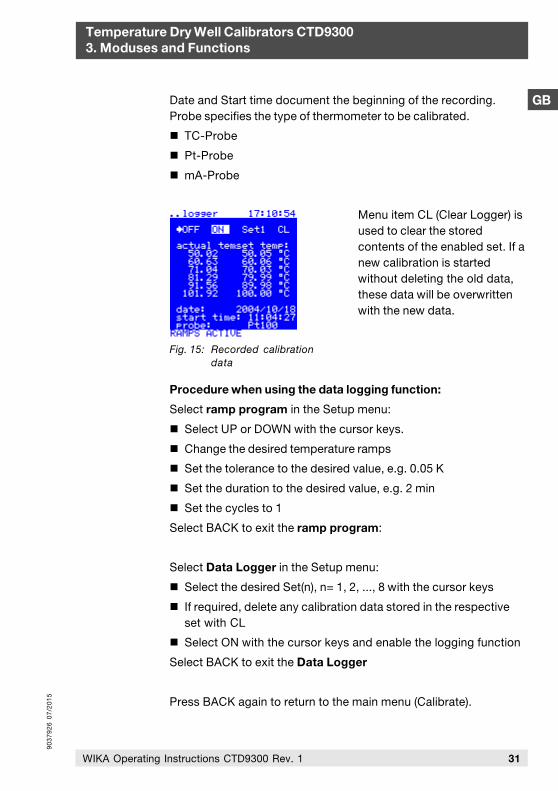
Date and Start time document the beginning of the recording.Probe specifies the type of thermometer to be calibrated.
TC-Probe
Pt-Probe
mA-Probe
Menu item CL (Clear Logger) isused to clear the storedcontents of the enabled set. If anew calibration is startedwithout deleting the old data,these data will be overwrittenwith the new data.
Procedure when using the data logging function:
Select ramp program in the Setup menu:
Select UP or DOWN with the cursor keys.
Change the desired temperature ramps
Set the tolerance to the desired value, e.g. 0.05 K
Set the duration to the desired value, e.g. 2 min
Set the cycles to 1
Select BACK to exit the ramp program:
Select Data Logger in the Setup menu:
Select the desired Set(n), n= 1, 2, ..., 8 with the cursor keys
If required, delete any calibration data stored in the respectiveset with CL
Select ON with the cursor keys and enable the logging function
Select BACK to exit the Data Logger
Press BACK again to return to the main menu (Calibrate).
Fig. 15: Recorded calibrationdata
90
37
92
6 0
7/2
01
5
Temperature Dry Well Calibrators CTD93003. Moduses and Functions
GB
32 WIKA Operating Instructions CTD9300 Rev. 1
During the program run, you can toggle between the main menuand the data logging menu to display temperature levels alreadyprocessed.
Once the program run of the logging program has been completed,the ramp program and the data logger are automatically set to OFF.The calibration data recorded can either be displayed in the datalogging menu or downloaded via the RS 232 interface.
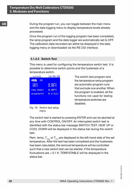
This menu is used for configuring the temperature switch test. It ispossible to determine switch points and the hysteresis of atemperature switch.
The switch test program andthe temperature ramp programare automatic program runsthat exclude one another. Whenthe program is enabled, all thefunctions not used for testingtemperature switches aredisabled.
The switch test is started by pressing ENTER and can be aborted atany time with CONTROL ON/OFF. An interrupted switch test isidentified with the status bar message SWITCH TEST. HEAT UP orCOOL DOWN will be displayed in the status bar during the switchtest.
Rem. temp, Tmax or Tmin are displayed to the left-hand side of the set
temperature. After the test has been completed and the hysteresishas been calculated, the removal temperature will be controlledsuch that a new switch test can be started. If the temperaturefluctuations are < 0.1 K, TEMP.STABLE will be displayed in thestatus bar.
3.1.2.2 Switch Test
Fig. 16: Switch test setupmenu
90
37
92
6 0
7/2
01
5
Temperature Dry Well Calibrators CTD93003. Moduses and Functions
GB
33WIKA Operating Instructions CTD9300 Rev. 1
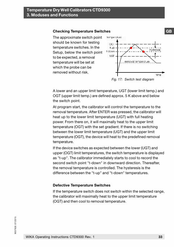
Fig. 17: Switch test diagram
Checking Temperature Switches
The approximate switch pointshould be known for testingtemperature switches. In theSetup, below the switch pointto be expected, a removaltemperature will be set atwhich the probe can beremoved without risk.
A lower and an upper limit temperature, UGT (lower limit temp.) andOGT (upper limit temp.) are defined approx. 5 K above and belowthe switch point.
At program start, the calibrator will control the temperature to theremoval temperature. After ENTER was pressed, the calibrator willheat up to the lower limit temperature (UGT) with full heatingpower. From there on, it will maximally heat to the upper limittemperature (OGT) with the set gradient. If there is no switchingbetween the lower limit temperature (UGT) and the upper limittemperature (OGT), the device will heat to the predefined removaltemperature.
If the device switches as expected between the lower (UGT) andupper (OGT) limit temperatures, the switch temperature is displayedas "t-up". The calibrator immediately starts to cool to record thesecond switch point "t-down" in downward direction. Thereafter,the removal temperature is controlled. The hysteresis is thedifference between the "t-up" and "t-down" temperatures.
Defective Temperature Switches
If the temperature switch does not switch within the selected range,the calibrator will maximally heat to the upper limit temperature(OGT) and then cool to removal temperature.
90
37
92
6 0
7/2
01
5
Temperature Dry Well Calibrators CTD93003. Moduses and Functions
GB
34 WIKA Operating Instructions CTD9300 Rev. 1
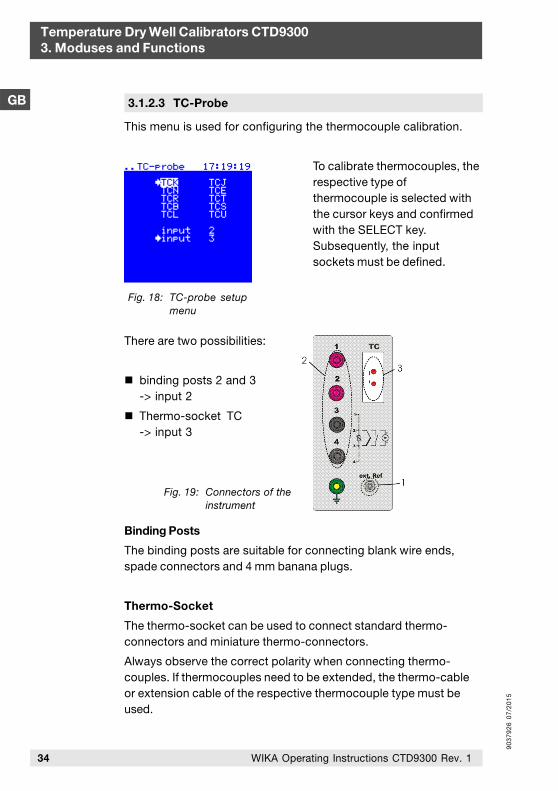
3.1.2.3 TC-Probe
This menu is used for configuring the thermocouple calibration.
To calibrate thermocouples, therespective type ofthermocouple is selected withthe cursor keys and confirmedwith the SELECT key.Subsequently, the inputsockets must be defined.
There are two possibilities:
binding posts 2 and 3-> input 2
Thermo-socket TC-> input 3
Binding Posts
The binding posts are suitable for connecting blank wire ends,spade connectors and 4 mm banana plugs.
Thermo-Socket
The thermo-socket can be used to connect standard thermo-connectors and miniature thermo-connectors.
Always observe the correct polarity when connecting thermo-couples. If thermocouples need to be extended, the thermo-cableor extension cable of the respective thermocouple type must beused.
Fig. 18: TC-probe setupmenu
Fig. 19: Connectors of theinstrument

90
37
92
6 0
7/2
01
5
GB
Temperature Dry Well Calibrators CTD93003. Moduses and Functions
35WIKA Operating Instructions CTD9300 Rev. 1
This menu is used for configuring the Pt resistance thermometercalibration.
To calibrate Pt resistancethermometers, the respectivetype of thermometer andconnection is selected with thecursor keys and confirmed withthe SELECT key. Theconnection is establishedexclusively via the bindingposts.
Binding posts
The binding posts are suitable for connecting blank wire ends,spade connectors lugs and 4 mm banana plugs. Take the requiredwiring technology into consideration for establishing connections.
There are three possibilities:
2-wires: terminals 2 + 3
3-wires: Terminals 3 + 4 loop, 2 + 3 Pt resistance
4-wires: Terminals 1 + 2/3 + 4 loop, 2 + 3 Pt resistance
Interchanging the connectors results in measurement faults.
3.1.2.4 Pt-Probe
Fig. 20: Pt-probesetup menu
90
37
92
6 0
7/2
01
5
Temperature Dry Well Calibrators CTD93003. Moduses and Functions
GB
36 WIKA Operating Instructions CTD9300 Rev. 1
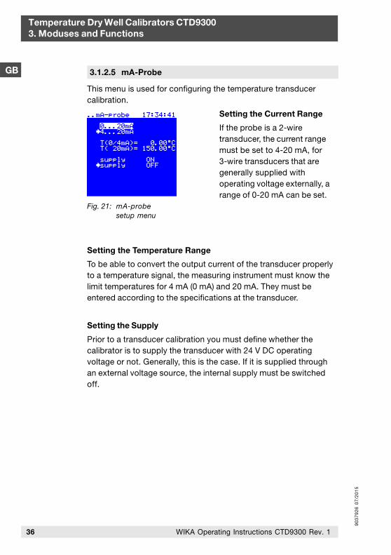
3.1.2.5 mA-Probe
This menu is used for configuring the temperature transducercalibration.
Setting the Current Range
If the probe is a 2-wiretransducer, the current rangemust be set to 4-20 mA, for3-wire transducers that aregenerally supplied withoperating voltage externally, arange of 0-20 mA can be set.
Setting the Temperature Range
To be able to convert the output current of the transducer properlyto a temperature signal, the measuring instrument must know thelimit temperatures for 4 mA (0 mA) and 20 mA. They must beentered according to the specifications at the transducer.
Setting the Supply
Prior to a transducer calibration you must define whether thecalibrator is to supply the transducer with 24 V DC operatingvoltage or not. Generally, this is the case. If it is supplied throughan external voltage source, the internal supply must be switchedoff.
Fig. 21: mA-probesetup menu
90
37
92
6 0
7/2
01
5
GB
Temperature Dry Well Calibrators CTD93003. Moduses and Functions
37WIKA Operating Instructions CTD9300 Rev. 1
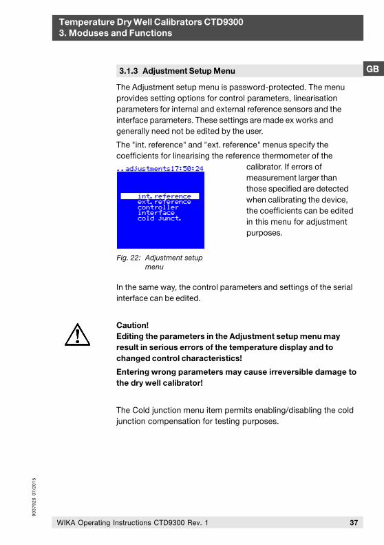
The Adjustment setup menu is password-protected. The menuprovides setting options for control parameters, linearisationparameters for internal and external reference sensors and theinterface parameters. These settings are made ex works andgenerally need not be edited by the user.
The "int. reference" and "ext. reference" menus specify thecoefficients for linearising the reference thermometer of the
calibrator. If errors ofmeasurement larger thanthose specified are detectedwhen calibrating the device,the coefficients can be editedin this menu for adjustmentpurposes.
In the same way, the control parameters and settings of the serialinterface can be edited.
Caution!Editing the parameters in the Adjustment setup menu mayresult in serious errors of the temperature display and tochanged control characteristics!
Entering wrong parameters may cause irreversible damage tothe dry well calibrator!
The Cold junction menu item permits enabling/disabling the coldjunction compensation for testing purposes.
3.1.3 Adjustment Setup Menu
Fig. 22: Adjustment setupmenu
90
37
92
6 0
7/2
01
5
Temperature Dry Well Calibrators CTD93003. Moduses and Functions
GB
38 WIKA Operating Instructions CTD9300 Rev. 1
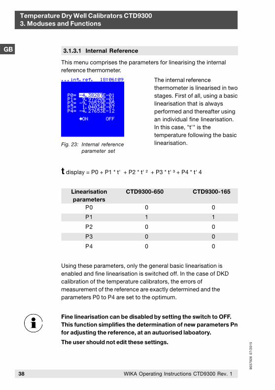
This menu comprises the parameters for linearising the internalreference thermometer.
The internal referencethermometer is linearised in twostages. First of all, using a basiclinearisation that is alwaysperformed and thereafter usingan individual fine linearisation.In this case, "t'" is thetemperature following the basiclinearisation.
t display = P0 + P1 * t' + P2 * t' ² + P3 * t' ³ + P4 * t' 4
Linearisation CTD9300-650 CTD9300-165parameters
P0 0 0
P1 1 1
P2 0 0
P3 0 0
P4 0 0
Using these parameters, only the general basic linearisation isenabled and fine linearisation is switched off. In the case of DKDcalibration of the temperature calibrators, the errors ofmeasurement of the reference are exactly determined and theparameters P0 to P4 are set to the optimum.
Fine linearisation can be disabled by setting the switch to OFF.This function simplifies the determination of new parameters Pnfor adjusting the reference, at an autuorised laboatory.
The user should not edit these settings.
3.1.3.1 Internal Reference
Fig. 23: Internal referenceparameter set
90
37
92
6 0
7/2
01
5
GB
Temperature Dry Well Calibrators CTD93003. Moduses and Functions
39WIKA Operating Instructions CTD9300 Rev. 1
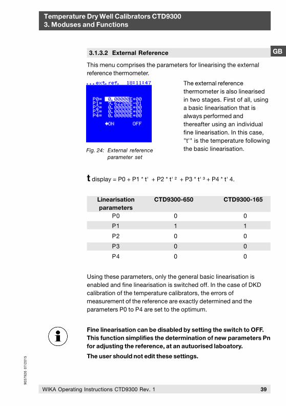
3.1.3.2 External Reference
This menu comprises the parameters for linearising the externalreference thermometer.
The external referencethermometer is also linearisedin two stages. First of all, usinga basic linearisation that isalways performed andthereafter using an individualfine linearisation. In this case,"t'" is the temperature followingthe basic linearisation.
t display = P0 + P1 * t' + P2 * t' ² + P3 * t' ³ + P4 * t' 4.
Linearisation CTD9300-650 CTD9300-165parameters
P0 0 0
P1 1 1
P2 0 0
P3 0 0
P4 0 0
Using these parameters, only the general basic linearisation isenabled and fine linearisation is switched off. In the case of DKDcalibration of the temperature calibrators, the errors ofmeasurement of the reference are exactly determined and theparameters P0 to P4 are set to the optimum.
Fine linearisation can be disabled by setting the switch to OFF.This function simplifies the determination of new parameters Pnfor adjusting the reference, at an autuorised laboatory.
The user should not edit these settings.
Fig. 24: External referenceparameter set
90
37
92
6 0
7/2
01
5
Temperature Dry Well Calibrators CTD93003. Moduses and Functions
GB
40 WIKA Operating Instructions CTD9300 Rev. 1
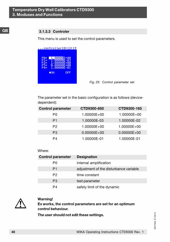
This menu is used to set the control parameters.
3.1.3.3 Controler
Fig. 25: Control parameter set
The parameter set in the basic configuration is as follows (device-dependent):
Control parameter CTD9300-650
P0 1.00000E+00
P1 1.00000E-03
P2 1.00000E+00
P3 0.00000E+00
P4 1.00000E-01
CTD9300-165
1.00000E+00
1.00000E-02
1.00000E+00
0.00000E+00
1.00000E-01
Where:
Control parameter Designation
P0 internal amplification
P1 adjustment of the disturbance variable
P2 time constant
P3 test parameter
P4 safety limit of the dynamic
Warning!Ex works, the control parameters are set for an optimumcontrol behaviour.
The user should not edit these settings.
90
37
92
6 0
7/2
01
5
GB
Temperature Dry Well Calibrators CTD93003. Moduses and Functions
41WIKA Operating Instructions CTD9300 Rev. 1
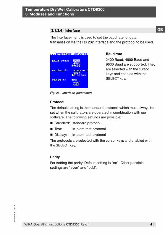
The Interface menu is used to set the baud rate for datatransmission via the RS 232 interface and the protocol to be used.
Baud rate
2400 Baud, 4800 Baud and9600 Baud are supported. Theyare selected with the cursorkeys and enabled with theSELECT key.
Protocol
The default setting is the standard protocol, which must always beset when the calibrators are operated in combination with oursoftware. The following settings are possible:
Standard: standard protocol
Test: in-plant test protocol
Display: in-plant test protocol
The protocols are selected with the cursor keys and enabled withthe SELECT key.
Parity
For setting the parity. Default setting is "no". Other possiblesettings are "even" and "odd".
3.1.3.4 Interface
Fig. 26: Interface parameters
90
37
92
6 0
7/2
01
5
Temperature Dry Well Calibrators CTD93003. Moduses and Functions
GB
42 WIKA Operating Instructions CTD9300 Rev. 1
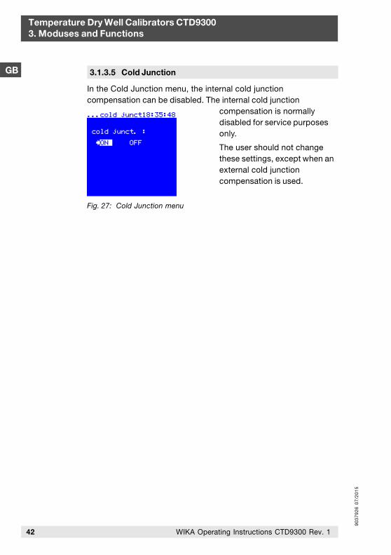
3.1.3.5 Cold Junction
In the Cold Junction menu, the internal cold junctioncompensation can be disabled. The internal cold junction
compensation is normallydisabled for service purposesonly.
The user should not changethese settings, except when anexternal cold junctioncompensation is used.
Fig. 27: Cold Junction menu
90
37
92
6 0
7/2
01
5
GB
Temperature Dry Well Calibrators CTD93003. Moduses and Functions
43WIKA Operating Instructions CTD9300 Rev. 1
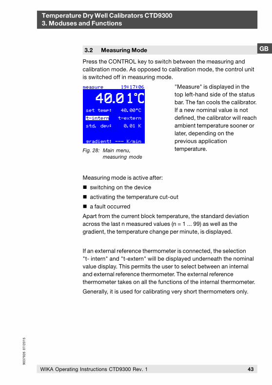
Press the CONTROL key to switch between the measuring andcalibration mode. As opposed to calibration mode, the control unitis switched off in measuring mode.
"Measure" is displayed in thetop left-hand side of the statusbar. The fan cools the calibrator.If a new nominal value is notdefined, the calibrator will reachambient temperature sooner orlater, depending on theprevious applicationtemperature.
Measuring mode is active after:
switching on the device
activating the temperature cut-out
a fault occurred
Apart from the current block temperature, the standard deviationacross the last n measured values (n = 1 ... 99) as well as thegradient, the temperature change per minute, is displayed.
If an external reference thermometer is connected, the selection"t- intern" and "t-extern" will be displayed underneath the nominalvalue display. This permits the user to select between an internaland external reference thermometer. The external referencethermometer takes on all the functions of the internal thermometer.
Generally, it is used for calibrating very short thermometers only.
3.2 Measuring Mode
Fig. 28: Main menu,measuring mode
90
37
92
6 0
7/2
01
5
44 WIKA Operating Instructions CTD9300 Rev. 1
Temperature Dry Well Calibrators CTD93003. Moduses and Functions
GB
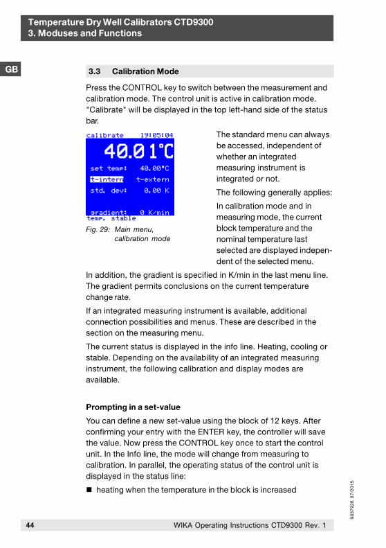
Press the CONTROL key to switch between the measurement andcalibration mode. The control unit is active in calibration mode."Calibrate" will be displayed in the top left-hand side of the statusbar.
The standard menu can alwaysbe accessed, independent ofwhether an integratedmeasuring instrument isintegrated or not.
The following generally applies:
In calibration mode and inmeasuring mode, the currentblock temperature and thenominal temperature lastselected are displayed indepen-dent of the selected menu.
In addition, the gradient is specified in K/min in the last menu line.The gradient permits conclusions on the current temperaturechange rate.
If an integrated measuring instrument is available, additionalconnection possibilities and menus. These are described in thesection on the measuring menu.
The current status is displayed in the info line. Heating, cooling orstable. Depending on the availability of an integrated measuringinstrument, the following calibration and display modes areavailable.
Prompting in a set-value
You can define a new set-value using the block of 12 keys. Afterconfirming your entry with the ENTER key, the controller will savethe value. Now press the CONTROL key once to start the controlunit. In the Info line, the mode will change from measuring tocalibration. In parallel, the operating status of the control unit isdisplayed in the status line:
heating when the temperature in the block is increased
3.3 Calibration Mode
Fig. 29: Main menu,calibration mode

90
37
92
6 0
7/2
01
5
45WIKA Operating Instructions CTD9300 Rev. 1
GB
Temperature Dry Well Calibrators CTD93003. Moduses and Functions
cooling when the block is cooled
temp. stable when a constant temperature has set in the block.
Selection between Internal and External ReferenceThermometer
If an external reference thermometer is connected, the selection"t- intern" and "t-extern" will be displayed underneath the nominalvalue display. This permits the user to select between an internaland external reference thermometer. The external referencethermometer takes on all the functions of the internal thermometer.
Generally, it is used for calibrating extremely short thermometersonly.
In the standard menu, the following values can be displayed on thecalibrator without an integrated measuring instrument.
Min/Max value
Standard Deviation
When the ramp program menuis enabled, the currenttemperature ramps 1 to 6 aredisplayed in the calibration andmeasuring modes instead ofthe set temperature.
3.3.1 Standard Menus
Fig. 30: Calibration menu"Data Logger"
90
37
92
6 0
7/2
01
5
Temperature Dry Well Calibrators CTD93003. Moduses and Functions
GB
46 WIKA Operating Instructions CTD9300 Rev. 1
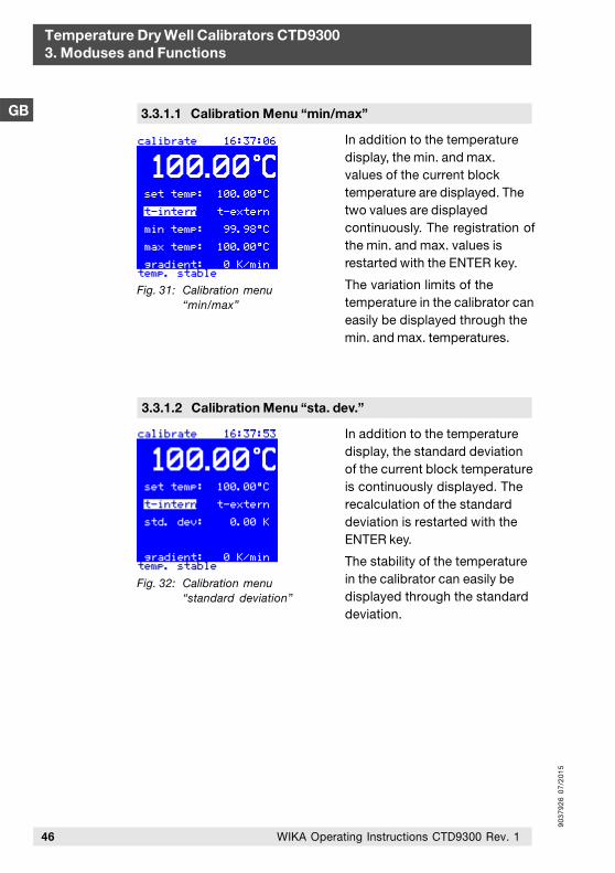
Fig. 31: Calibration menu“min/max”
In addition to the temperaturedisplay, the min. and max.values of the current blocktemperature are displayed. Thetwo values are displayedcontinuously. The registration ofthe min. and max. values isrestarted with the ENTER key.
The variation limits of thetemperature in the calibrator caneasily be displayed through themin. and max. temperatures.
3.3.1.1 Calibration Menu “min/max”
Fig. 32: Calibration menu“standard deviation”
In addition to the temperaturedisplay, the standard deviationof the current block temperatureis continuously displayed. Therecalculation of the standarddeviation is restarted with theENTER key.
The stability of the temperaturein the calibrator can easily bedisplayed through the standarddeviation.
3.3.1.2 Calibration Menu “sta. dev.”

90
37
92
6 0
7/2
01
5
3.3.2.1 Calibration Menu “Switch Test”
GB
Temperature Dry Well Calibrators CTD93003. Moduses and Functions
47WIKA Operating Instructions CTD9300 Rev. 1
3.3.2 Measuring Instrument Menus
If the calibrator is equipped with an integrated measuringinstrument, a measuring instrument menu is available in addition tothe standard menu. This comprises the following functions:
Temperature switch test
Thermocouple calibration
Pt resistance thermometer calibration
4-20 mA transducer calibration
The selection of external and internal reference thermometer isprovided only, if an external reference thermometer is connected.
The deviation of the probe is either specified in comparison to theinternal or external reference, depending on which of the tworeferences is enabled.
If the "Ramp Program" menu orthe "Data Logger" function isenabled, the currenttemperature ramps 1 to 6 willbe displayed in the calibrationand measuring modes insteadof the set temperature.
Fig. 33: Calibration menu"Data Logger"
In this menu, the switchingtemperatures can be displayedin addition to the nominal andactual temperatures of thecalibrator.
Fig. 34: Calibration menu"switch test"
90
37
92
6 0
7/2
01
5
Temperature Dry Well Calibrators CTD93003. Moduses and Functions
GB
48 WIKA Operating Instructions CTD9300 Rev. 1
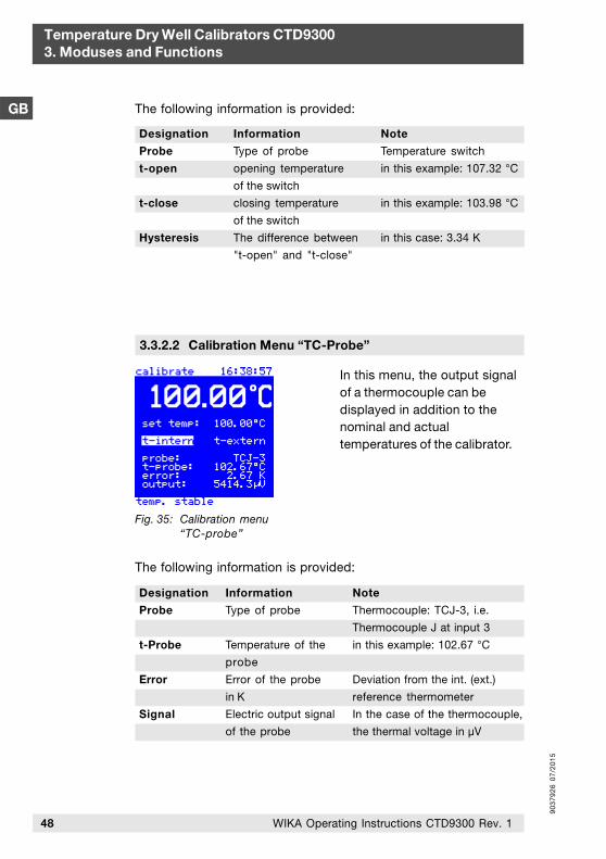
Designation
Probe
t-open
t-close
Hysteresis
Information
Type of probe
opening temperature
of the switch
closing temperature
of the switch
The difference between
"t-open" and "t-close"
Note
Temperature switch
in this example: 107.32 °C
in this example: 103.98 °C
in this case: 3.34 K
The following information is provided:
3.3.2.2 Calibration Menu “TC-Probe”
In this menu, the output signalof a thermocouple can bedisplayed in addition to thenominal and actualtemperatures of the calibrator.
Fig. 35: Calibration menu“TC-probe”
The following information is provided:
Designation
Probe
t-Probe
Error
Signal
Information
Type of probe
Temperature of the
probe
Error of the probe
in K
Electric output signal
of the probe
Note
Thermocouple: TCJ-3, i.e.
Thermocouple J at input 3
in this example: 102.67 °C
Deviation from the int. (ext.)
reference thermometer
In the case of the thermocouple,
the thermal voltage in µV
90
37
92
6 0
7/2
01
5
GB
Temperature Dry Well Calibrators CTD93003. Moduses and Functions
49WIKA Operating Instructions CTD9300 Rev. 1
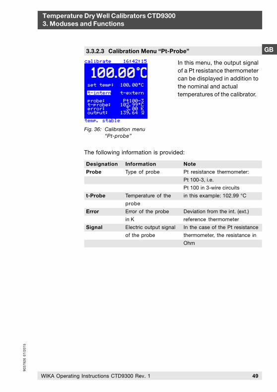
3.3.2.3 Calibration Menu “Pt-Probe”
In this menu, the output signalof a Pt resistance thermometercan be displayed in addition tothe nominal and actualtemperatures of the calibrator.
Fig. 36: Calibration menu“Pt-probe”
The following information is provided:
Designation
Probe
t-Probe
Error
Signal
Information
Type of probe
Temperature of the
probe
Error of the probe
in K
Electric output signal
of the probe
Note
Pt resistance thermometer:
Pt 100-3, i.e.
Pt 100 in 3-wire circuits
in this example: 102.99 °C
Deviation from the int. (ext.)
reference thermometer
In the case of the Pt resistance
thermometer, the resistance in
Ohm
90
37
92
6 0
7/2
01
5
Temperature Dry Well Calibrators CTD93003. Moduses and Functions
GB
50 WIKA Operating Instructions CTD9300 Rev. 1
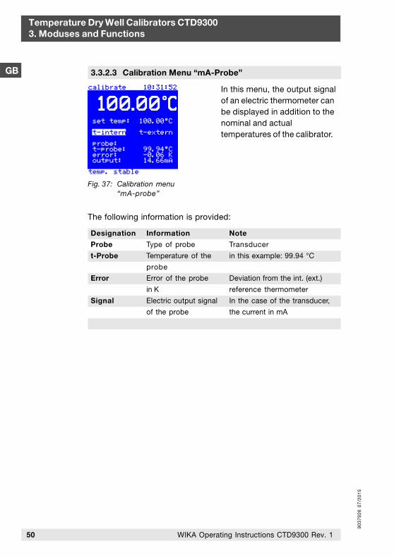
In this menu, the output signalof an electric thermometer canbe displayed in addition to thenominal and actualtemperatures of the calibrator.
3.3.2.3 Calibration Menu “mA-Probe”
Fig. 37: Calibration menu“mA-probe”
Note
Transducer
in this example: 99.94 °C
Deviation from the int. (ext.)
reference thermometer
In the case of the transducer,
the current in mA
Designation
Probe
t-Probe
Error
Signal
Information
Type of probe
Temperature of the
probe
Error of the probe
in K
Electric output signal
of the probe
The following information is provided:
90
37
92
6 0
7/2
01
5
GB
Temperature Dry Well Calibrators CTD93004. Operating the Calibrator
51WIKA Operating Instructions CTD9300 Rev. 1
4.1 Setup and Connection
4. Operating the Calibrator
Connect the power cable supplied to the calibrator and plug thepower connector into the mains socket. Set up the calibrator suchthat the fan on the bottom of the device has sufficient free space tobe able to circulate a sufficient cooling air rate. Insufficient ventingmay cause damage leading to the destruction of the calibrator.
Set up the calibrator such that the power switch (switch for powersupply) is easily accessible and can be actuated without anyproblems.
Caution!Since the housing of the calibrator is made of metal, only powercables with ground wire may be used. Use the power cablesupplied.
Caution!Ensure that all the bores of the heating block are clean and freeof damage. Do not use any filling media.
Place the calibrator in an upright position for the calibrationprocedure to ensure optimum temperature distribution andtransmission.
Additionally take the following into consideration:
the probe
the adapting sleeve and
the bore of the heating block
must exactly match.
Keep the thermal contact resistance as low as possible by usingadapting sleeves with test bores, the inside diameters of which areapprox. 0.2 mm to max. 0.5 mm larger than the diameter of theprobe.
90
37
92
6 0
7/2
01
5
Temperature Dry Well Calibrators CTD93004. Operating the Calibrator
GB
52 WIKA Operating Instructions CTD9300 Rev. 1
Connect the device to a power circuit with minimum risk of a powerfailure, since it will no longer be possible to supply cooling air inthe case of a power failure.
4.2 Starting Procedure
If the calibrator is not used for an extended period of time, a smallamount of humidity may collect due to the hygroscopiccharacteristic of the magnesium oxide used as insulating materialin the heating system.
After transporting or storing the device in a humid environment, theheating elements must thus be heated slowly when starting thecalibrator. During the drying process, the device will not haveattained the isolation voltage required for protection class I.
The nominal startup value is Tanf = 120 °C at a dwell time ofth = 15 min.
4.3 Initial Use
Checks prior to initial use
Prior to initial use, the devices must be moved to their standardupright operating position. When installing the device, make surethat the fan on the bottom can circulate a sufficient rate of air. Donot use soft, resilient surfaces.
Remove all highly combustible material from the vicinity of thedevice and ensure that the device cannot come into contact witheasily inflammable or explosive media.
Proceed as follows:
Check the technical data specified on the type label.
Always place the CTD9300 in an upright position. Otherwise uniform temperature distribution in the block cannot be ensured.
Do not use any filling media.
90
37
92
6 0
7/2
01
5
GB
Temperature Dry Well Calibrators CTD93004. Operating the Calibrator
53WIKA Operating Instructions CTD9300 Rev. 1
Check and ensure the following:
The calibrator must be complete. An adapting sleeve with aninside diameter of 6.5 mm, appropriate for probes with adiameter of 6 mm, a sleeve removal tool, a power cable, anRS 232 interface cable and operating instructions are standardaccessories.
The probe and the adapting sleeve as well as the bore of theblock must match exactly to keep the thermal contact resistanceas low as possible.
The mains voltage must match the supply voltage specified onthe type label.
The device must be connected to a power circuit with minimumrisk of a power failure, since it will no longer be possible tosupply cooling air in the case of a power failure.
All the bores of the adapting sleeve must be clean and free ofdamage and foreign matters.
After activation via the power switch and switchover fromstandby to standard operation, the fan must start when button(B) is pressed.
Calibrators with a hot dry well always bear an imminent hazard ofburns.
Risk of burns!Depending on the type, the dry well of a calibrator may reachtemperatures of up to 650 °C.
Let the calibrator cool after use. Only transport the calibrator after ithas cooled completely. The dry well temperature should be below30 °C.
When touching the surface of the heating block, the adaptingsleeve or the probe, or even when approaching them, there may bean imminent hazard of burns. Never touch these surfaces if you arenot absolutely sure that these parts are cold.
4.4 Cooling of the Block and Replacing the Sleeve
90
37
92
6 0
7/2
01
5
54 WIKA Operating Instructions CTD9300 Rev. 1
Temperature Dry Well Calibrators CTD93004. Operating the Calibrator
GB Never leave the temperature calibrator unattended during or afteruse. Wait until the heating block has reached room temperature, i.e.25 °C before packaging it.
You can accelerate the cooling process by setting the testingtemperature to the smallest value possible.
Also take care when replacing the adapting sleeves!
Risk of burns!The adapting sleeves may reach temperatures of up to 650 °C.Remove the inserts only when they have cooled.
Use a sleeve removal tool for removing the adapting sleeve, press ittogether and insert it into the bores provided on the adaptingsleeve.
Then cautiously pull the sleeve straight up out of the block withoutcanting it.
Place the sleeve on a solid, temperature resistant surface.
Do not let the adapting sleeve inserts fall. The edges may bedamaged which may lead to jamming of the sleeve when sliding itback in the block.
4.5 Application Examples
Type CTD9300-165 for the range of from - 30 °C to 165 °C
In the bio-pharmaceutical and food industry as well as in the fieldof heating, air conditioning and ventilation, temperatures between0 °C and 100 °C are often measured. With its fast Peltier elements,each temperature can be attained within a few minutes. Thealuminium block accommodates adapting sleeves of thedimensions Ø 28 mm x 150 mm. It can even be used to calibratemultiple typical thermometers at the same time.
Type CTD9300-650 for the range of from 40 °C to 650 °C
In the technical service and measurement and control workshop,temperature dry well calibrators are used for calibrating electricthermometers and for adjusting temperature transducers. With its
90
37
92
6 0
7/2
01
5
55WIKA Operating Instructions CTD9300 Rev. 1
GB
Temperature Dry Well Calibrators CTD93004. Operating the Calibrator
large temperature range of from 40 °C to 650 °C, the CTD9300- 650 is a universally applicable allround calibrator that can be adapted to various calibration requirements.
Irrespective of whether transducers are to be adjusted or temperature sensors are to be calibrated on test benches, the CTD9300650 has been proven and tested in numerous calibration tasks, in the laboratory, in the workshop and on site.
Calibrating Thermometers < 150 mm
If probes cannot be inserted down to the bottom of the adaptingsleeve due to insufficient sheath length, the heat dissipation errorproduced can be considerably reduced by using an externalreference thermometer. For this purpose, an adapting sleeve withtwo test bores is used.
The probe and the reference thermometer are inserted to the samedepth in the adapting sleeve. After switching to "t-extern", theexternal reference thermometer will take on the measuring andcontrol tasks.
The minimum insertion depth of probe and reference should notdrop below 70 mm since the control system changes and thestability gets worse when the reference thermometer is notimmersed deep enough. In addition, it will take longer until a stabletemperature is attained.
If probes are inserted to a depth less than 150 mm, the uncertaintyof measurement will increase during calibration. It is not possible tomake a general statement in this case, since with a low immersiondepth, factors such as:
Sheath diameter
Heat conductivity of the sheath material
Sensitive sensor length
Ambient temperature
considerably affect the uncertainty of measurement.
If short probes are to be calibrated frequently using the CTD9300, this fact can be considered individually on customer request when adjusting and calibrating the CTD9300, even in the measurement uncertainty budget.
90
37
92
6 0
7/2
01
5
56 WIKA Operating Instructions CTD9300 Rev. 1
Temperature Dry Well Calibrators CTD93004. Operating the Calibrator
GB
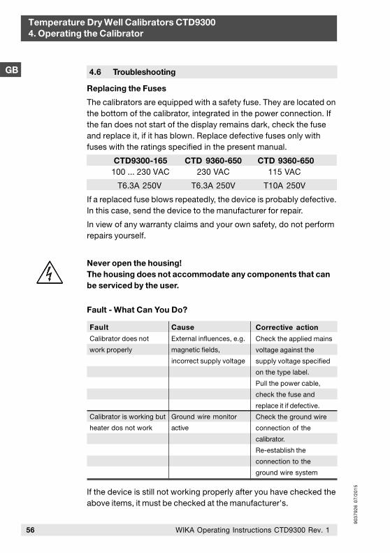
Corrective action
Check the applied mains
voltage against the
supply voltage specified
on the type label.
Pull the power cable,
check the fuse and
replace it if defective.
Check the ground wire
connection of the
calibrator.
Re-establish the
connection to the
ground wire system
Cause
External influences, e.g.
magnetic fields,
incorrect supply voltage
Ground wire monitor
active
Fault
Calibrator does not
work properly
Calibrator is working but
heater dos not work
Fault - What Can You Do?
If the device is still not working properly after you have checked theabove items, it must be checked at the manufacturer's.
4.6 Troubleshooting
Replacing the Fuses
The calibrators are equipped with a safety fuse. They are located onthe bottom of the calibrator, integrated in the power connection. Ifthe fan does not start of the display remains dark, check the fuseand replace it, if it has blown. Replace defective fuses only withfuses with the ratings specified in the present manual.
CTD 9360-650 CTD 9360-650CTD9300-165 100 ... 230 VAC 230 VAC 115 VAC
T6.3A 250V T6.3A 250V T10A 250V
If a replaced fuse blows repeatedly, the device is probably defective.In this case, send the device to the manufacturer for repair.
In view of any warranty claims and your own safety, do not performrepairs yourself.
Never open the housing!The housing does not accommodate any components that canbe serviced by the user.
90
37
92
6 0
7/2
01
5
57WIKA Operating Instructions CTD9300 Rev. 1
GB
Temperature Dry Well Calibrators CTD93004. Operating the Calibrator
4.7 Recalibration and Adjustment
The temperature calibrators of the CTD9300 series have been calibrated and tested ex works according to accepted standards. Recalibration and adjustment of the device, however, is recommend if used periodically.
There are no compulsory regulations for recalibration intervals oftemperature calibrators since these depend on the conditions ofapplication and are thus in the responsibility of the user.
Independent of this fact, we recommend annual recalibration at ourDKD calibration laboratory. Any recalibration performed by WIKAadditionally includes free checking of the functions and internalsystem parameters. During this process, any errors of measurementare reduced to a minimum within the scope of measurementuncertainty by proper adjustment. Firmware updates can also beperformed.
The DKD calibration certificate also gives you the certainty thatyour calibration results are based on national standards and theerrors of measurement do not exceed the error limits specified.
Calibration is a matter of trust. For this reason, entrust onlycompetent DKD calibration laboratories that has been certified incompliance with the standard DIN EN ISO/IEC 17025 with thecalibration of your valuable devices.
Package the devices you are shipping for recalibration with greatcare and use the original packaging, if possible.
To guarantee that the calibration process is performed as fast aspossible, we recommend contacting our calibration workshop byphone in advance to make an appointment.
Call our calibration laboratory or send an e-mail.
WIKA Alexander Wiegand SE & Co. KG Alexander-Wiegand-Straße 30D-63911 KlingenbergPhone no.: (+49) 93 72/132-5049Fax no.: (+49) 93 72/[email protected]
The address of our laboratory:
90
37
92
6 0
7/2
01
5
58 WIKA Operating Instructions CTD9300 Rev. 1
Temperature Dry Well Calibrators CTD93004. Operating the Calibrator
GB 4.8 Notes of the DKD
Extract from the instructions of the DKD expert committee”Temperature and Humidity” on the use of temperature dry wellcalibrators.
The calibration certificate of a DKD calibration laboratory confirmsthat the temperature dry well calibrator fulfils the high demandsplaced on the calibration capabilities of a calibrator of that kind, asdefined in guide line DKD-R 5-4. Nevertheless, the following issuesmust be taken into consideration when using the calibrator:
The calibration of temperature dry well calibrators primarily refers tothe temperature of the solid block. The temperature of thethermometer to be calibrated in the block can deviate from thattemperature. If a thermometer of the same type under the samemeasuring conditions as used for the calibration is used, it can beassumed that the errors of measurement when calibrating idealthermometers is not larger than the errors of measurementspecified in the calibration certificate.
If not specified otherwise in the calibration certificate, it must beensured that:
the measuring element is in a homogenous temperature zone.
the inside diameter of the bore or adapting sleeve used in thecalibrator in the temperature range of from -80 °C to 660 °C ismax. 0.5 mm and in the temperature range of from 660 °C to1,300 °C max. 1.0 mm larger than the outside diameter of thethermometer to be calibrated.
the immersion depth of the thermometer to be calibrated is atleast 15 times the outside diameter of the thermometer to becalibrated.
the thermometer to be calibrated has an outside diameter ofd <_ 6 mm.
When calibrating thermometers with an outside diameter ofd > 6 mm, an additional error of measurement due to heatdissipation must be taken into consideration.
If measurements of this kind are to be performed, the additionalheat dissipation for the thermometer type you are testing can bedetermined by your DKD calibration laboratory.
90
37
92
6 0
7/2
01
5
59WIKA Operating Instructions CTD9300 Rev. 1
GB
Temperature Dry Well Calibrators CTD93004. Operating the Calibrator
A good test for assessing potential temperature deviations due toheat dissipation is to check whether the reading of thethermometer to be calibrated changes if it is lifted by 20 mm.Contributions to the error of measurement caused by thethermometer to be calibrated (e.g. inhomogeneity ofthermocouples) are not taken into consideration in the errors ofmeasurement of the calibrator either.
If the calibrator is used under load conditions that do notcorrespond to the load condition during calibration, the influencefactor of the load can be determined on site by removing orinserting thermometers.
The specifications in the calibration certificate are authoritative forthe calibration, not the specifications of the manufacturer. Pleasediscuss the application and calibration conditions with our DKDcalibration laboratory prior to the calibration.
If not specified otherwise in the calibration certificate, it must beensured that:
the calibrator is operated in vertical position.
no additional thermic isolation is used.
the ambient temperature is (23 +_ 5) °C.
To check the calibration of temperature dry well calibrators, werecommend periodical measurements using a calibratedthermometer. Without verification measurements using a calibratedthermometer, we strongly recommend annual recalibration of thetemperature dry well calibrator.
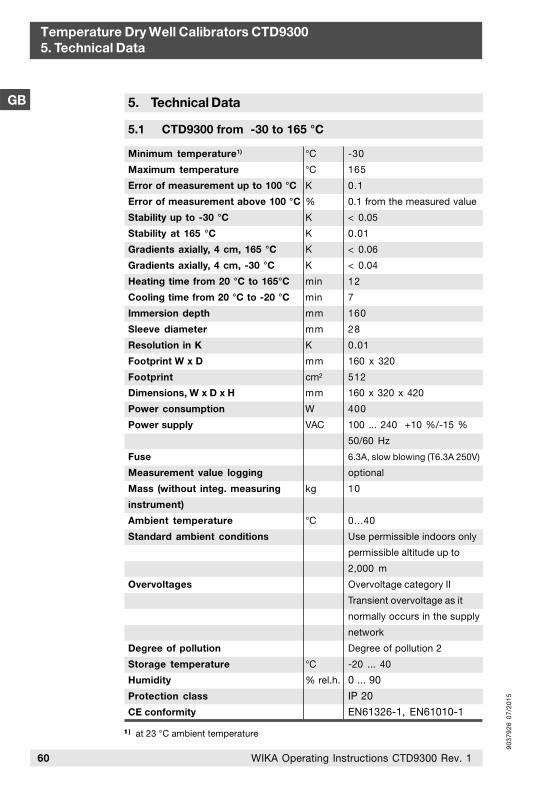
90
37
92
6 0
7/2
01
5
60 WIKA Operating Instructions CTD9300 Rev. 1
Temperature Dry Well Calibrators CTD93005. Technical Data
GB 5. Technical Data
5.1 CTD9300 from -30 to 165 °C
Minimum temperature1)
Maximum temperature
Error of measurement up to 100 °C
Error of measurement above 100 °C
Stability up to -30 °C
Stability at 165 °C
Gradients axially, 4 cm, 165 °C
Gradients axially, 4 cm, -30 °C
Heating time from 20 °C to 165°C
Cooling time from 20 °C to -20 °C
Immersion depth
Sleeve diameter
Resolution in K
Footprint W x D
Footprint
Dimensions, W x D x H
Power consumption
Power supply
Fuse
Measurement value logging
Mass (without integ. measuring
instrument)
Ambient temperature
Standard ambient conditions
Overvoltages
Degree of pollution
Storage temperature
Humidity
Protection class
CE conformity
°C
°C
K
%
K
K
K
K
min
min
mm
mm
K
mm
cm²
mm
W
VAC
kg
°C
°C
% rel.h.
-30
165
0.1
0.1 from the measured value
< 0.05
0.01
< 0.06
< 0.04
12
7
160
28
0.01
160 x 320
512
160 x 320 x 420
400
100 ... 240 +10 %/-15 %
50/60 Hz
6.3A, slow blowing (T6.3A 250V)
optional
10
0...40
Use permissible indoors only
permissible altitude up to
2,000 m
Overvoltage category II
Transient overvoltage as it
normally occurs in the supply
network
Degree of pollution 2
-20 ... 40
0 ... 90
IP 20
EN61326-1, EN61010-1
1 )1 )1 )1 )1 ) at 23 °C ambient temperature
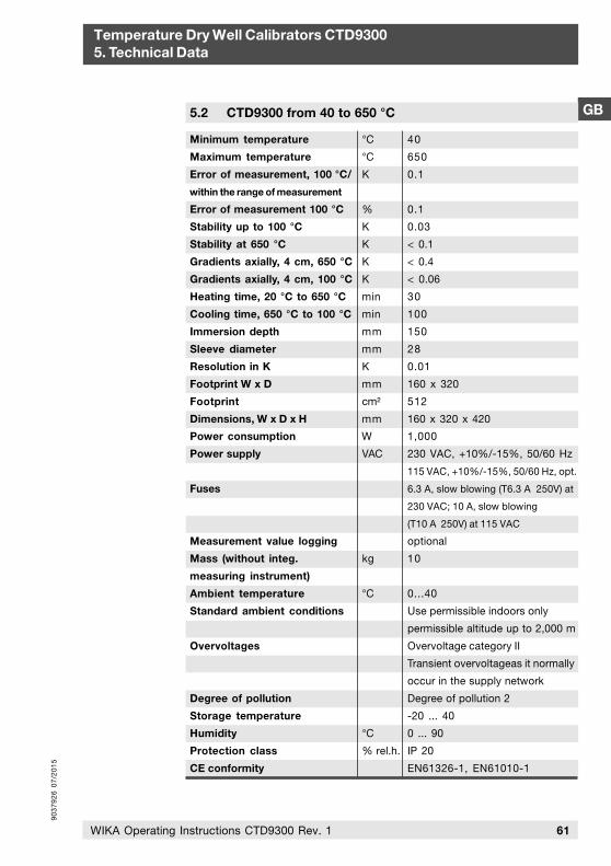
90
37
92
6 0
7/2
01
5
61WIKA Operating Instructions CTD9300 Rev. 1
GB
Temperature Dry Well Calibrators CTD93005. Technical Data
5.2 CTD9300 from 40 to 650 °C
Minimum temperature
Maximum temperature
Error of measurement, 100 °C/
within the range of measurement
Error of measurement 100 °C
Stability up to 100 °C
Stability at 650 °C
Gradients axially, 4 cm, 650 °C
Gradients axially, 4 cm, 100 °C
Heating time, 20 °C to 650 °C
Cooling time, 650 °C to 100 °C
Immersion depth
Sleeve diameter
Resolution in K
Footprint W x D
Footprint
Dimensions, W x D x H
Power consumption
Power supply
Fuses
Measurement value logging
Mass (without integ.
measuring instrument)
Ambient temperature
Standard ambient conditions
Overvoltages
Degree of pollution
Storage temperature
Humidity
Protection class
CE conformity
°C
°C
K
%
K
K
K
K
min
min
mm
mm
K
mm
cm²
mm
W
VAC
kg
°C
°C
% rel.h.
40
650
0.1
0.1
0.03
< 0.1
< 0.4
< 0.06
30
100
150
28
0.01
160 x 320
512
160 x 320 x 420
1,000
230 VAC, +10%/-15%, 50/60 Hz
115 VAC, +10%/-15%, 50/60 Hz, opt.
6.3 A, slow blowing (T6.3 A 250V) at
230 VAC; 10 A, slow blowing
(T10 A 250V) at 115 VAC
optional
10
0...40
Use permissible indoors only
permissible altitude up to 2,000 m
Overvoltage category II
Transient overvoltageas it normally
occur in the supply network
Degree of pollution 2
-20 ... 40
0 ... 90
IP 20
EN61326-1, EN61010-1
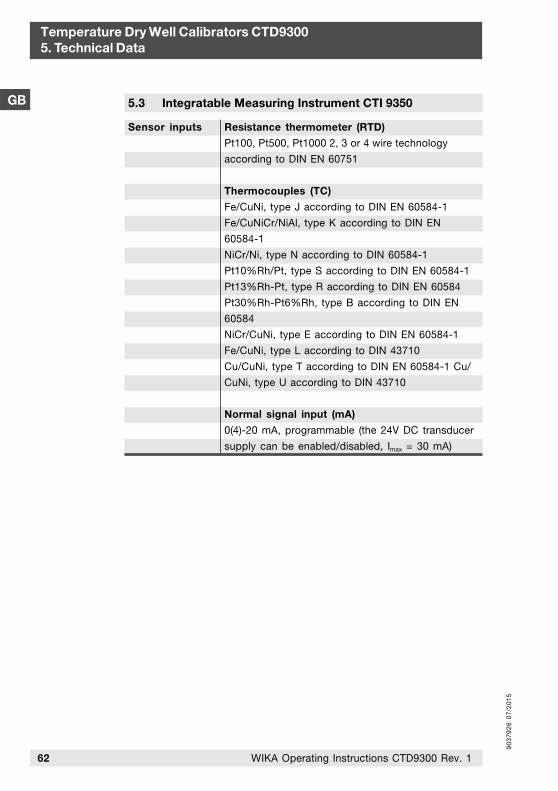
90
37
92
6 0
7/2
01
5
62 WIKA Operating Instructions CTD9300 Rev. 1
Temperature Dry Well Calibrators CTD93005. Technical Data
GB 5.3 Integratable Measuring Instrument CTI 9350
Resistance thermometer (RTD)
Pt100, Pt500, Pt1000 2, 3 or 4 wire technology
according to DIN EN 60751
Thermocouples (TC)
Fe/CuNi, type J according to DIN EN 60584-1
Fe/CuNiCr/NiAl, type K according to DIN EN
60584-1
NiCr/Ni, type N according to DIN 60584-1
Pt10%Rh/Pt, type S according to DIN EN 60584-1
Pt13%Rh-Pt, type R according to DIN EN 60584
Pt30%Rh-Pt6%Rh, type B according to DIN EN
60584
NiCr/CuNi, type E according to DIN EN 60584-1
Fe/CuNi, type L according to DIN 43710
Cu/CuNi, type T according to DIN EN 60584-1 Cu/
CuNi, type U according to DIN 43710
Normal signal input (mA)
0(4)-20 mA, programmable (the 24V DC transducer
supply can be enabled/disabled, Imax = 30 mA)
Sensor inputs
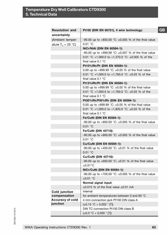
90
37
92
6 0
7/2
01
5
63WIKA Operating Instructions CTD9300 Rev. 1
GB
Temperature Dry Well Calibrators CTD93005. Technical Data
Cold junction compensation
Resolution and
uncertainty
(Ambient temper-
ature TU = 25 °C)
Pt100 (DIN EN 60751), 4 wire technology:
-90.00 up to +850.00 °C: ±0.005 % of the final value 0.01 °C
NiCr/NiAl (DIN EN 60584-1):-90.00 up to +999.99 °C: ±0.007 % of the final value 0.01 °C +1,000.0 to +1,370.0 °C: ±0.005 % of the final value 0.1 °C
Pt10%Rh/Pt (DIN EN 60584-1):0.00 up to +999.99 °C: ±0.05 % of the final value 0.01 °C +1,000.0 to +1,760.0 °C: ±0.03 % of the final value 0.1 °C
Pt13%Rh/Pt (DIN EN 60584-1):0.00 up to +999.99 °C: ±0.05 % of the final value 0.01 °C +1,000.0 to +1,760.0 °C: ±0.03 % of the final value 0.1 °C
Pt30%Rh/Pt6%Rh (DIN EN 60584-1):0.00 up to +999.99 °C: ±0.05 % of the final value 0.01 °C +1,000.0 to +1,820.0 °C: ±0.03 % of the final value 0.1 °C
Fe/CuNi (DIN EN 60584-1):-90.00 up to +900.00 °C: ±0.005 % of the final value 0.01 °C
Fe/CuNi (DIN 43710):-90.00 up to +900.00 °C: ±0.005 % of the final value 0.01 °C
Cu/CuNi (DIN EN 60584-1):-90.00 up to +400.00 °C: ±0.01 % of the final value 0.01 °C
Cu/CuNi (DIN 43710):-90.00 up to +600.00 °C: ±0.01 % of the final value±0.01°C
NiCr/CuNi (DIN EN 60584-1):-90.00 up to +700.00 °C: ±0.005 % of the final value±0.01 °C
Normal signal input:±0.015 % of the final value ±0.01 mAinternalfor ambient temperatures between 0 and 60 °C4 mm connection jack Pt100 DIN class A(±0,15 °C + 0,002 * [T])DIN TC-connection Pt100 DIN class B(±0,3 °C + 0,005 * [T])
Accuracy of cold junction
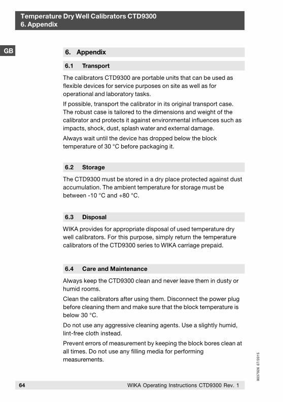
90
37
92
6 0
7/2
01
5
64 WIKA Operating Instructions CTD9300 Rev. 1
Temperature Dry Well Calibrators CTD93006. Appendix
GB
The calibrators CTD9300 are portable units that can be used as flexible devices for service purposes on site as well as for operational and laboratory tasks.
If possible, transport the calibrator in its original transport case.The robust case is tailored to the dimensions and weight of thecalibrator and protects it against environmental influences such asimpacts, shock, dust, splash water and external damage.
Always wait until the device has dropped below the blocktemperature of 30 °C before packaging it.
6.2 Storage
The CTD9300 must be stored in a dry place protected against dust accumulation. The ambient temperature for storage must be between -10 °C and +80 °C.
6. Appendix
6.1 Transport
6.3 Disposal
WIKA provides for appropriate disposal of used temperature dry well calibrators. For this purpose, simply return the temperature calibrators of the CTD9300 series to WIKA carriage prepaid.
6.4 Care and Maintenance
Always keep the CTD9300 clean and never leave them in dusty or humid rooms.
Clean the calibrators after using them. Disconnect the power plugbefore cleaning them and make sure that the block temperature isbelow 30 °C.
Do not use any aggressive cleaning agents. Use a slightly humid,lint-free cloth instead.
Prevent errors of measurement by keeping the block bores clean atall times. Do not use any filling media for performingmeasurements.
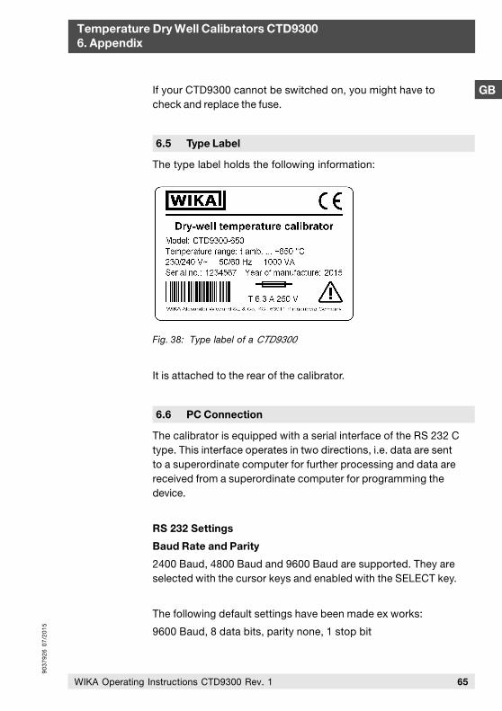
90
37
92
6 0
7/2
01
5
65WIKA Operating Instructions CTD9300 Rev. 1
GB
Temperature Dry Well Calibrators CTD93006. Appendix
6.5 Type Label
The type label holds the following information:
It is attached to the rear of the calibrator.
Fig. 38: Type label of a CTD9300
6.6 PC Connection
The calibrator is equipped with a serial interface of the RS 232 Ctype. This interface operates in two directions, i.e. data are sentto a superordinate computer for further processing and data arereceived from a superordinate computer for programming thedevice.
RS 232 Settings
Baud Rate and Parity
2400 Baud, 4800 Baud and 9600 Baud are supported. They areselected with the cursor keys and enabled with the SELECT key.
The following default settings have been made ex works:
9600 Baud, 8 data bits, parity none, 1 stop bit
If your CTD9300 cannot be switched on, you might have to check and replace the fuse.
90
37
92
6 0
7/2
01
5
66 WIKA Operating Instructions CTD9300 Rev. 1
Temperature Dry Well Calibrators CTD93006. Appendix
GB Protocol
3 protocol formats are available:
Standard: The standard protocol, which must always be setwhen the calibrators are operated in combinationwith our calibration program.
Test: in-plant test protocol
Display: in-plant test protocol
The protocol types are selected with the cursor keys and enabledwith the SELECT key.
Command Set
The command set is not an integral part of the present operatinginstructions. Users interested in the command set may ask themanufacturer for a copy.
Pin Layout of the RS 232 Cable
PC and dry well calibrator can be connected using a standard1:1-RS 232 cable.

90
37
92
6 0
7/2
01
5

90
37
92
6 0
7/2
01
5
90
37
92
6 0
7/2
01
5
69
Inhalt
WIKA Betriebsanleitung CTD9300 Rev. 1
D
Temperatur-Blockkalibratoren Typen CTD9300 Inhalt
Inhalt
1. Allgemeine Hinweise 71
2. Gerätebeschreibung 75
3. Modi und Funktionen 87
4. Betreiben des Kalibrators 117
5. Technische Daten 127
6. Anhang 131
Information!Dieses Zeichen gibt Ihnen Informationen, Hinweise oder Tipps.
Achtung!Allgemeine Gefahrenstelle!Bitte beachten Sie die Betriebsanleitung.
Gefahr!Mögliche Personenschäden durch elektrische Spannung.
Gefahr!Mögliche Personenschäden durch hohe Temperaturen.
90
37
92
6 0
7/2
01
5
70 WIKA Betriebsanleitung CTD9300 Rev. 1
D Vorwort
Temperatur-Blockkalibratoren Typen CTD9300 Vorwort
WIKA Alexander Wiegand SE & Co. KG Alexander-Wiegand-Straße 30D-63911 KlingenbergTel.: (+49) 93 72/132-0Fax: (+49) 93 72/[email protected]
Wir gratulieren Ihnen zum Kauf Ihres WIKA Temperatur-Blockkali-brators aus der CTD9300-Familie. Diese Kalibratorenfamilie umfasst z. Zt. zwei Geräte für verschiedene Temperaturbereiche:
CTD9300-165 von -30 °C bis 165 °C
CTD9300-650 von 40 °C bis 650 °C
Da die Bedienung der Geräte weitgehend identisch ist, haben wiruns für eine gemeinsame Betriebsanleitung der beiden Geräteentschieden.
Die Betriebsanleitung richtet sich an Facharbeiter und angelernteArbeitskräfte. Lesen Sie vor jedem Arbeitsschritt die dazugehörigenHinweise sorgfältig durch und halten Sie die vorgegebene Reihen-folge ein.
Lesen Sie den Abschnitt "Allgemeine Hinweise" besonders auf-merksam durch. Prägen Sie sich die Bildzeichen (Piktogramme) undihre Bedeutung gut ein.
Das Gerät ist zur Kalibrierung von Temperaturschaltern, Thermoele-menten, Widerstandsthermometern und mechanischen Thermome-tern vorgesehen. Benutzen Sie sie bitte entsprechend dieserBestimmung.
Sollten Sie Probleme oder Fragen haben, wenden Sie sich an IhrenLieferanten oder direkt an den Hersteller:
90
37
92
6 0
7/2
01
5
71WIKA Betriebsanleitung CTD9300 Rev. 1
D
Temperatur-Blockkalibratoren Typen CTD93001. Allgemeine Hinweise
1. Allgemeine Hinweise
1.1 Grundlegende Sicherheitshinweise
Beachten Sie bei allen Arbeiten an dem Gerät die nationalenSicherheits- und Unfallverhütungsvorschriften und die nachfol-genden Sicherheitshinweise in dieser Betriebsanleitung.
Das Gerät wird über das Netzkabel mit einer für Menschen gefähr-lichen Spannung versorgt.
Der einwandfreie und sichere Betrieb dieses Gerätes setzt sachge-mäßen Transport, fachgerechte Lagerung, Aufstellung undbestimmmungsgemäßen Gebrauch sowie sorgfältige Bedienungund Instandhaltung voraus.
Ein anderer Betrieb als der in der folgenden Anleitung beschriebeneist bestimmungswidrig und muss deshalb ausgeschlossen werden.
Können Störungen nicht beseitigt werden, ist das Gerät unverzüg-lich außer Betrieb zu setzen und gegen versehentliche Inbetrieb-nahme zu schützen.
Gefahr!
Reparaturen dürfen nur vom Hersteller durchgeführt werden.Eingriffe und Änderungen am Gerät sind unzulässig.
Vor dem Austauschen der Schmelzsicherung ist das Gerät durchZiehen des Netzkabels aus der Netzsteckdose von der Netzspan-nung zu trennen.
Weitere wichtige Sicherheitshinweise befinden sich in den einzel-nen Abschnitten dieser Anleitung.
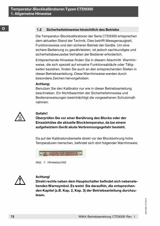
90
37
92
6 0
7/2
01
5
72
Temperatur-Blockkalibratoren Typen CTD93001. Allgemeine Hinweise
WIKA Betriebsanleitung CTD9300 Rev. 1
D 1.2 Sicherheitshinweise hinsichtlich des Betriebs
Die Temperatur-Blockkalibratoren der Serie CTD9300 entsprechen dem aktuellen Stand der Technik. Dies betrifft Messgenauigkeit, Funktionsweise und den sicheren Betrieb der Geräte. Um eine sichere Bedienung zu gewährleisten, ist jedoch sachkundiges und sicherheitsbewusstes Verhalten der Bediener erforderlich.
Entsprechende Hinweise finden Sie in diesem Abschnitt. Warnhin-weise, die sich speziell auf einzelne Funktionsabläufe oder Tätig-keiten beziehen, finden Sie auch an den entsprechenden Stellen indieser Betriebsanleitung. Diese Warnhinweise werden durchbesondere Zeichen hervorgehoben.
Achtung:Benutzen Sie den Kalibrator nur wie in dieser Betriebsanleitungbeschrieben. Ein Nichtbeachten der Sicherheitshinweise undBedienanweisungen beeinträchtigt die vorgesehenen Schutzmaß-nahmen.
Gefahr!Überprüfen Sie vor einer Berührung des Blocks oder derEinsatzhülse die aktuelle Blocktemperatur, da bei einemaufgeheiztem Gerät akute Verbrennungsgefahr besteht.
Da auf der Kalibratoroberseite direkt vor der Blockbohrung hoheTemperaturen herrschen, befindet sich dort folgender Warnhinweis:
Achtung!Direkt rechts neben dem Hauptschalter befindet sich nebenste-hendes Warnsymbol. Es weist Sie daraufhin, die entsprechen-den Kapitel (z.B. Kap. 2, Kap. 3) der Betriebsanleitung durchzu-lesen.
Abb. 1: Hinweisschild
90
37
92
6 0
7/2
01
5
73WIKA Betriebsanleitung CTD9300 Rev. 1
Temperatur-Blockkalibratoren Typen CTD93001. Allgemeine Hinweise
DSicherheitshinweise:
Entfernen Sie alle leicht brennbaren Medien aus der Nähe desGerätes und stellen Sie sicher, dass sie nicht mit leicht entzünd-lichen oder explosionsgefährdeten Stoffen in Verbindungkommen können.
Sorgen Sie dafür, dass die eingebauten Lüfter immer ausrei-chend Kühlluft fördern können. Behindern Sie die Luftzufuhrnicht durch Aufstellung der Geräte auf eine weiche, nachgiebigeUnterlage.
Schließen Sie die Geräte an einen Stromkreis an, bei dem dieGefahr eines Netzausfalles möglichst gering ist, da bei Netzaus-fall keine Kühlluft mehr gefördert werden kann.
Stellen Sie sicher, dass Einsatzhülsen und Prüflinge nicht mitMedien (z.B. Öl) verunreinigt sind, die bei einem Aufheizen zurEntzündung oder Explosion führen können.
Entfernen Sie aus einem aufgeheiztem Block niemals Einsatz-hülsen, da von der aufgeheizten Anpassungshülse Brandgefahrausgehen kann.
Entfernen Sie aus einem aufgeheiztem Block niemals Prüflinge,da akute Verbrennungsgefahr besteht.
Lassen Sie ein aufgeheiztes Gerät niemals ohne Aufsicht.
Lassen Sie ein aufgeheiztes Gerät stets unter 50 °C abkühlen,bevor Sie es vom Netz trennen.
Versuchen Sie niemals, selbst am Gerät Reparaturen auszufüh-ren sondern wenden Sie sich an den Hersteller.
Da das Gehäuse des Kalibrators aus Metall besteht, darf nur einNetzkabel mit Schutzleiter verwendet werden. Betreiben Sie denKalibrator nur mit dem mitgelieferten Netzkabel. Der Netzkabel-zugang befindet sich an der Unterseite des Kalibrators, so dasses bei Verwendung eines anderen Kabeltyps zum Kippen desKalibrators kommen kann.
Bei längerem Nichtgebrauch des Kalibrators ist es möglich, dassaufgrund des verwendeten Materials (Magnesiumxoid) Feuchtigkeitin das Heizelement eindringt. Nach Transport oder Lagerung desKalibrators in feuchter Umgebung müssen die Heizelemente daherbeim Anheizen langsam hochgeheizt werden. Während des Aus-trocknungsvorganges ist davon auszugehen, dass der Kalibrator
90
37
92
6 0
7/2
01
5
74 WIKA Betriebsanleitung CTD9300 Rev. 1
Temperatur-Blockkalibratoren Typen CTD93001. Allgemeine Hinweise
D noch nicht die für die Schutzklasse I erforderliche Isolations-spannung erreicht hat.
Die Geräuschwerte aller Blockkalibratoren der Serie CTD9300 liegen unterhalb 70 dbA.
1.4 Sorgfaltspflicht des Betreibers
Für ein sicheres Arbeiten mit dem Gerät muss der Betreiber insbe-sondere sicherstellen, dass
das Gerät nur bestimmungsgemäß genutzt wird (vergl. denAbschnitt “Bestimmungsgemäße Verwendung” im Kapitel“2. Gerätebeschreibung”) sowie keine gefährlichen Medienverwendet und sämtliche technischen Spezifikationen eingehal-ten werden.
das Gerät nur in einwandfreiem, funktionstüchtigem Zustandbetrieben wird.
die Betriebsanleitung stets in einem leserlichen Zustand undvollständig am Einsatzort des Gerätes zur Verfügung steht.
jeweils nur autorisiertes und qualifiziertes Personal das Gerätbedient, wartet und instand setzt.
der Bediener bzw. die Bedienerin des Gerätes regelmäßig in allenzutreffenden Fragen von Arbeitssicherheit und Umweltschutzunterwiesen wird sowie die Betriebsanleitung und insbesonderedie darin enthaltenen Sicherheitshinweise kennt.
1.3 Schutzleiterüberwachung
Der Kalibrator ist zur Kontrolle der Basisisolation der Heizung miteiner Schutzleiterüberwachung ausgestattet. Die Überwachungs-einheit arbeitet unabhängig von der übrigen Steuerung undschaltet, sobald der Kalibrator keine Verbindung mehr zum Schutz-leitersystem der Isolation hat, die Stromversorgung der Heizung ab.
Ist die Verbindung zum Schutzleitersystem wieder hergestellt,schaltet die Überwachungseinheit den Heizkreis automatischwieder an die Stromversorgung an.
90
37
92
6 0
7/2
01
5
75WIKA Betriebsanleitung CTD9300 Rev. 1
Temperatur-Blockkalibratoren Typen CTD93002. Gerätebeschreibung
D2. Gerätebeschreibung
2.1 Bestimmungsgemäße Verwendung
Die Kalibratoren der Serie CTD9300 dürfen ausschließlich für die Kalibrierung und Überprüfung von Thermoelementen, Widerstandsthermometern, mechanischen Thermometern und Temperaturschaltern eingesetzt werden.
Das Einbringen fremder Stoffe in den Kalibrator, wie zum BeispielÖl oder Wärmeleitpaste, mit dem Ziel, den Wärmeübergang auf denPrüfling zu verbessern, kann zur Beschädigung des Kalibrators undseiner Einsatzhülse führen.
Desweiteren besteht Verletzungsgefahr durch plötzlich verdamp-fende Flüssigkeiten und durch gefährliche Gase, die sich beimVerdampfen von Flüssigkeiten bilden können.
Achten Sie stets darauf, dass die Prüftemperatur für den Prüflingnicht zu hoch ist. Der Prüfling kann sonst zerstört werden.
Entfernen Sie alle leicht brennbaren Medien aus der Nähe desGerätes und stellen Sie sicher, dass das Gerät nicht mit leichtentzündlichen oder explosionsgefährdeten Medien in Verbin-dung kommen kann.
2.2 Aufbau
Temperatur-Blockkalibratoren bestehen aus einem elektrischbeheizten Metallblock und einem Regelteil. Beide Komponentensind zusammen mit einem Lüfter in einem robusten Metallgehäuseuntergebracht. Der Metallblock besitzt in der Mitte eine Bohrungzur Aufnahme der sogenannten Einsatzhülse. Diese Einsatzhülseenthält eine oder mehrere Bohrungen unterschiedlichen Durchmes-sers, die es ermöglichen, Thermometer unterschiedlicher Dicke anden temperierten Block thermisch optimal anzukoppeln. Eine gutethermische Verbindung zwischen Block, Einsatzhülse und Thermo-meter ist im Hinblick auf kleine Messunsicherheiten beim Kalibrie-ren sehr wichtig.
90
37
92
6 0
7/2
01
5
76 WIKA Betriebsanleitung CTD9300 Rev. 1
Temperatur-Blockkalibratoren Typen CTD93002. Gerätebeschreibung
D Kalibratoren für tiefe Temperaturen
Erzeugt der Kalibrator Temperaturen unterhalb der Umgebungs-temperatur, so muss er aktiv kühlen können. In diesem Fall bestehtder isothermale Block aus Aluminium und wird mit sogenanntenPeltierelementen gekühlt und geheizt. Je nach Polarität der ange-legten Spannung erwärmt sich das Peltierelement an seinerOberseite während die gegenüberliegende Seite gekühlt wird. EineSeite des Elementes liegt immer am isothermalen Block an. Dieandere Seite ist mit einem Kühlkörper verbunden, der von einemstarken Gebläse gekühlt wird.
Durch Umpolen und Regeln der Spannung an den Peltierelementenist es möglich, den Block zu heizen wie auch zu kühlen. Austechnischen Gründen ist die maximal mit Peltierelementen erziel-bare Temperatur auf ca. 165 °C begrenzt. Die minimal erreichbareTemperatur beträgt je nach Ausführungsform -50 K bis -60 Kgegenüber der Umgebungstemperatur.
Kalibratoren für hohe Temperaturen
Hochtemperatur-Kalibratoren für Temperaturbereiche von 40 °C bis650 °C arbeiten in der Regel mit Widerstandsheizelementen. Jenach oberer Grenztemperatur kommen unterschiedliche Block-materialien zum Einsatz: Messing, Bronze oder zunderbeständigeStähle.
Die Regelung beginnt wegen der zu tiefen Temperaturen aufgrundstetig geringer werdender Kühlwirkung des den Block umgebendenLuftstromes erst 20 K oberhalb der jeweiligen Umgebungs-temperatur hinreichend schnell zu arbeiten. Dadurch ist die untereEinsatztemperatur eines solchen Gerätes auf ca. 40 °C begrenzt.
Nach oben hin ist die Einsatzgrenze durch das verwendete Block-material und die Temperaturbeständigkeit der eingesetztenHeizelemente gegeben.
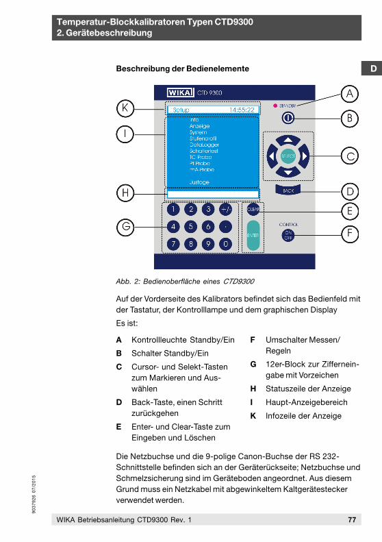
90
37
92
6 0
7/2
01
5
77WIKA Betriebsanleitung CTD9300 Rev. 1
Temperatur-Blockkalibratoren Typen CTD93002. Gerätebeschreibung
D
Abb. 2: Bedienoberfläche eines CTD9300
Auf der Vorderseite des Kalibrators befindet sich das Bedienfeld mitder Tastatur, der Kontrolllampe und dem graphischen Display
Es ist:
Beschreibung der Bedienelemente
A Kontrollleuchte Standby/Ein
B Schalter Standby/Ein
C Cursor- und Selekt-Tastenzum Markieren und Aus-wählen
D Back-Taste, einen Schrittzurückgehen
E Enter- und Clear-Taste zumEingeben und Löschen
F Umschalter Messen/Regeln
G 12er-Block zur Ziffernein-gabe mit Vorzeichen
H Statuszeile der Anzeige
I Haupt-Anzeigebereich
K Infozeile der Anzeige
Die Netzbuchse und die 9-polige Canon-Buchse der RS 232-Schnittstelle befinden sich an der Geräterückseite; Netzbuchse undSchmelzsicherung sind im Geräteboden angeordnet. Aus diesemGrund muss ein Netzkabel mit abgewinkeltem Kaltgerätesteckerverwendet werden.
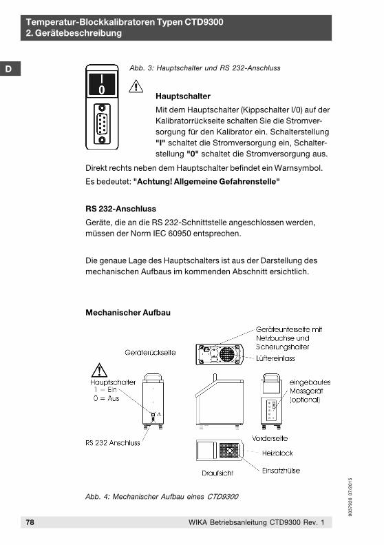
90
37
92
6 0
7/2
01
5
78 WIKA Betriebsanleitung CTD9300 Rev. 1
Temperatur-Blockkalibratoren Typen CTD93002. Gerätebeschreibung
D
Hauptschalter
Mit dem Hauptschalter (Kippschalter I/0) auf derKalibratorrückseite schalten Sie die Stromver-sorgung für den Kalibrator ein. Schalterstellung"I" schaltet die Stromversorgung ein, Schalter-stellung "0" schaltet die Stromversorgung aus.
Abb. 3: Hauptschalter und RS 232-Anschluss
Direkt rechts neben dem Hauptschalter befindet ein Warnsymbol.
Es bedeutet: "Achtung! Allgemeine Gefahrenstelle"
RS 232-Anschluss
Geräte, die an die RS 232-Schnittstelle angeschlossen werden,müssen der Norm IEC 60950 entsprechen.
Die genaue Lage des Hauptschalters ist aus der Darstellung desmechanischen Aufbaus im kommenden Abschnitt ersichtlich.
Mechanischer Aufbau
Abb. 4: Mechanischer Aufbau eines CTD9300
90
37
92
6 0
7/2
01
5
79WIKA Betriebsanleitung CTD9300 Rev. 1
Temperatur-Blockkalibratoren Typen CTD93002. Gerätebeschreibung
D2.3 Funktionsbeschreibung
Unabhängig von den voneinander verschiedenen Heizprinzipien- Peltierelemente bei der 165 °C Variante und Widerstandsheiz-elemente beim 650 °C Typ - haben beide Geräte die gleichenBedienfunktionen.
CTD9300-165 für den Bereich -30 °C bis 165 °C
CTD9300-650 für den Bereich 40 °C bis 650 °C
Beide Temperatur-Blockkalibratoren sind ausgestattet mit einemelektronisch temperaturgeregeltem Heizblock aus Metall. DieserHeizblock ist mit einer Bohrung 28 mm x 150 mm versehen, die derAufnahme der Einsatzhülse dient.
In diese Heizblockbohrung können Anpassungshülsen, diesogenannten Einsatzhülsen, mit einer oder mehreren Prüf-bohrungen eingesteckt werden, welche die Funktion eines Adap-ters zwischen Prüfling (Temperaturschalter, Thermoelement,Thermometer, Widerstandsthermometer) und Heizblockbohrungübernehmen. Der Heizblock ist gegenüber der Gehäusewandthermisch isoliert.
Im mittleren Bereich der graphischen Anzeige (I) wird die Tempera-tur des Heizblocks und der eingestellte Sollwert mit einer Auflö-sung von 0,01 K dargestellt.
Die gewünschte Heizblocktemperatur wird mit Hilfe des 12er-Blocks (G) vorgegeben. Nach der Bestätigung des neuen Soll-wertes mit der Enter-Taste (E) und Umschalten vom Mess- in denRegelmodus mit Control-Taste (F) beginnt der Regler denKalibrator auf die aktuelle Solltemperatur einzustellen.
In der Info-Zeile (K) ändert sich der angezeigte Modus von Messenauf Kalibrieren. In der Statuszeile (H) erscheinen je nach Betriebs-zustand HEIZEN, KÜHLEN und STABIL.
Die Temperatur gilt als STABIL, wenn sie sich innerhalb von 5 s umweniger als 0,1 K ändert. Nur bei aktivem Stufenprogramm ist dieSTABIL-Anzeige von den eingestellten Stabilitätskreterien Toleranzund Dauer abhängig.
Zusätzlich zur aktuellen Blocktemperatur können der eingestellteSollwert sowie entweder die Standardabweichung oder die Min-und Maxwerte der Blocktemperatur angezeigt werden. Mit Hilfedieser Angaben kann schon auf den ersten Blick eine Aussage über
90
37
92
6 0
7/2
01
5
80 WIKA Betriebsanleitung CTD9300 Rev. 1
Temperatur-Blockkalibratoren Typen CTD93002. Gerätebeschreibung
2.4 Standardzubehör
Netzkabel
Ein Netzkabel mit um 90 ° abgewinkeltem Kaltgerätestecker für dieStromversorgung liegt jedem Kalibrator bei. Entsprechend demLand der Auslieferung ist das Netzkabel mit dem landesspezi-fischen Netzstecker versehen.
Einsatzhülse
Jeder Kalibrator wird werkseitig mit einer Einsatzhülse mit Innen-durchmesser von 6,5 mm ausgeliefert. Damit lassen sich diemeisten industriellen Thermometer an den Kalibrator anpassen.
Sollten Ihre Thermometer abweichende Durchmesser aufweisen,bestellen Sie bitte die gewünschte Einsatzhülse mit einer Innen-bohrung entsprechend Ihres Thermometerduchmessers zuzüglich0,5 mm.
Hülsenwechselwerkzeug
Ein Hülsenwechselwerkzeug zum einfachen, sicheren Herausneh-men und Einstecken der Einsatzhülsen in den Kalibratorblock gehört zum Standardzubehör eines jeden Temperaturkalibrators der Serie CTD9300.
Datenkabel
Ein Datenkabel zum Verbinden des Kalibrators mit der RS 232-Schnittstelle liegt jedem Gerät bei. Der PIN-Belegungsplan für 9-und 25-polige Sub-D-Stecker befindet sich im Anhang, sieheAbschnitt 6.6: PC-Anschluss.
2.5 Sonderzubehör
Das Sonderzubehör ist im Standard-Lieferumfang nicht enthalten.
D die Stabilität der Temperatur im Kalibrator gemacht werden.
Standardabweichung sowie Min- und Maxwert können durcheinmaliges Betätigen der ENTER-Taste (E) zurückgesetzt werden.
90
37
92
6 0
7/2
01
5
81WIKA Betriebsanleitung CTD9300 Rev. 1
Temperatur-Blockkalibratoren Typen CTD93002. Gerätebeschreibung
D
2.5.2 Transportkoffer
Als Option bieten wir Ihnen zu Ihrem Kalibrator einen robustenTransportkoffer an. Wir empfehlen den Einsatz des Transport-koffers, wenn Sie das Gerät häufig für Vor-Ort-Kalibrierungeneinsetzen und es deshalb oft transportieren müssen.
Der Koffer schützt Ihren Kalibrator nicht nur vor Umwelteinflüssenwie Staub, Schmutz und Feuchtigkeit sondern auch vor mechani-scher Beschädigung wie sie durch Stoß und Vibration auftretenkönnen.
2.5.1 Sondereinsatzhülsen
Hülsen für die Kalibratoren CTD9300-165 bestehen aus Alumini-um, Hülsen für CTD9300-650 sind aus Messing gefertigt. Beide Hülsen besitzen die Außenabmessungen Ø 28 mm x 150 mm lang.
Sondereinsatzhülsen können auf Kundenwunsch in den verschie-densten Ausführungen gefertigt werden. Auch Hülsen mit Mehr-fachbohrungen sind hier möglich. Grenzen werden lediglich durchdie mechanische Bearbeitbarkeit der Hülsenrohlinge gesetzt.
Bei der Hülsenauslegung sollte jedoch beachtet werden, dass sichmit zunehmender Anzahl von Bohrungen wie auch mit wachsen-dem Bohrungsdurchmesser die Gesamtmessunsicherheit desKalibrators verschlechtert.
Die tatsächliche Messunsicherheit bei der Verwendung einerSonder-Einsatzhülse kann erst bei genauer Kenntnis derBohrungsdurchmesser und Anzahl sowie der Bauform und Mate-rialien der zu kalibrierenden Thermometer abgeschätzt werden.
Sollten Sie Mehrfachhülsen wünschen, berücksichtigen Sie bitte,dass
die Bohrungen wegen einer gleichmäßigen Temperaturverteilungmöglichst auf einem Teilkreis angeordnet sein sollten.
aus fertigungstechnischen Gründen ein Mindestabstandzwischen den Bohrungen und auch zum Hülsenrand hinbestehen muss. Dieser Abstand sollte im Regelfall nicht wenigerals 2 mm betragen.
der Bohrungsdurchmesser mindestens 7 % größer sein sollteals der des zu prüfenden Thermometers.

90
37
92
6 0
7/2
01
5
82 WIKA Betriebsanleitung CTD9300 Rev. 1
Temperatur-Blockkalibratoren Typen CTD93002. Gerätebeschreibung
D 2.5.3 Integrierbare Messwerterfassung
In der Mess- und Regelwerkstatt wird ein Messgerät zum An-schluss an den Prüfling benötigt, das Thermospannungen, Wider-stand und 4-20 mA Normsignale misst und in Grad C anzeigt.
Im Zusammenspiel mit den Kalibratoren der Familie CTD9300 bildet die integrierbare Messwerterfassung CTI 9350 eine sinnvolle Ergänzung Ihrer Kalibrierausrüstung. Das Messgerät lässt sich in das Gehäuse der CTD9300 Kalibratoren integrieren. Bestellen Sie die Messwerterfassung CTI 9350 direkt mit oder lassen Sie sie später nachrüsten. Wir bieten Ihnen beide Möglichkeiten. Bei einer Nachrüstung wird im Werk einfach die Vorderfront des Kalibrators ausgetauscht.
Die Temperaturen beider Thermometer - Referenz und Prüfling -können gleichzeitig auf dem Display angezeigt und einfach mitein-ander verglichen werden.
Als Prüflinge können angeschlossen werden:
Widerstandsthermometer: Pt 100, Pt 500 und Pt 1000 in 2-, 3-oder 4-Leiterschaltung
Thermoelemente der Typen K, J, N, E, R, T, B, S, L und U sowie
4-20 mA Stromsignale von Temperaturtransmittern, mit undohne Versorgungsspannung
Temperaturschalter mit "Schließern" und "Öffnern"
Der Anschluss des Referenz-Widerstandsthermometers erfolgt miteinem 7-poligen Binderstecker.
Für den Prüfling sind drei verschiedene Anschlussmöglichkeitenvorgesehen:
Polklemmen für 4 mm Stecker, Gabelkabelschuhe und blankeDrähte
Standard - Thermostecker
Miniatur -Thermostecker
Zum Anschluss der Widerstandsthermometer, Temperaturschalterund 4-20 mA-Signale werden generell die 4 mm-Buchsen verwen-det (1, 2, 3 und 4). Für die Thermoelemente stehen alle dreiVerbindungsvarianten zur Verfügung.
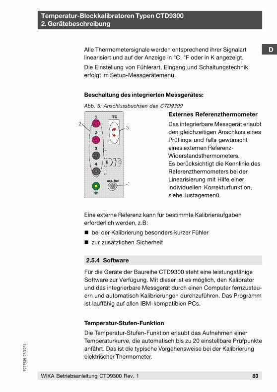
90
37
92
6 0
7/2
01
5
83WIKA Betriebsanleitung CTD9300 Rev. 1
Temperatur-Blockkalibratoren Typen CTD93002. Gerätebeschreibung
DAlle Thermometersignale werden entsprechend ihrer Signalartlinearisiert und auf der Anzeige in °C, °F oder in K angezeigt.
Die Einstellung von Fühlerart, Eingang und Schaltungstechnikerfolgt im Setup-Messgerätemenü.
Beschaltung des integrierten Messgerätes:
Externes Referenzthermometer
Das integrierbare Messgerät erlaubtden gleichzeitigen Anschluss einesPrüflings und falls gewünschteines externen Referenz-Widerstandsthermometers.Es berücksichtigt die Kennlinie desReferenzthermometers bei derLinearisierung mit Hilfe einerindividuellen Korrekturfunktion,siehe Justagemenü.
Eine externe Referenz kann für bestimmte Kalibrieraufgabenerforderlich werden, z.B:
bei der Kalibrierung besonders kurzer Fühler
zur zusätzlichen Sicherheit
Abb. 5: Anschlussbuchsen des CTD9300
2.5.4 Software
Für die Geräte der Baureihe CTD9300 steht eine leistungsfähige Software zur Verfügung. Mit dieser ist es möglich, den Kalibrator und das integrierbare Messgerät durch einen Computer fernzusteu-ern und automatisch Kalibrierungen durchzuführen. Das Programm ist lauffähig auf allen IBM-kompatiblen PCs.
Temperatur-Stufen-Funktion
Die Temperatur-Stufen-Funktion erlaubt das Aufnehmen einerTemperaturkurve, die automatisch bis zu 20 einstellbare Prüfpunkteanfährt. Das ist die typische Vorgehensweise bei der Kalibrierungelektrischer Thermometer.
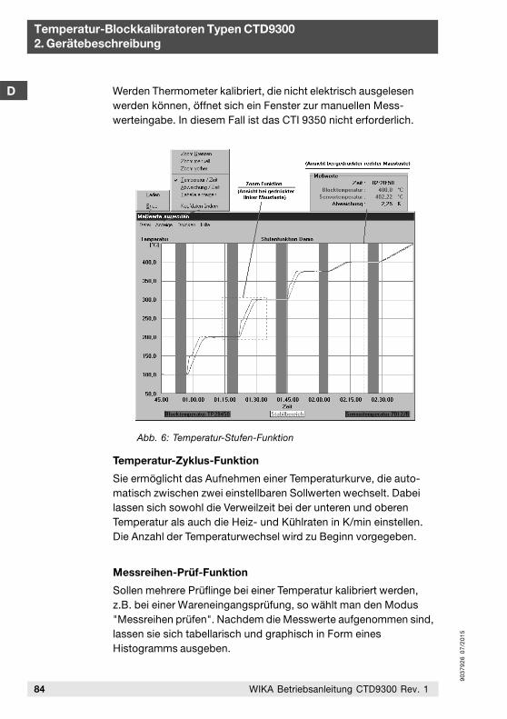
90
37
92
6 0
7/2
01
5
84 WIKA Betriebsanleitung CTD9300 Rev. 1
Temperatur-Blockkalibratoren Typen CTD93002. Gerätebeschreibung
D Werden Thermometer kalibriert, die nicht elektrisch ausgelesenwerden können, öffnet sich ein Fenster zur manuellen Mess-werteingabe. In diesem Fall ist das CTI 9350 nicht erforderlich.
Temperatur-Zyklus-Funktion
Sie ermöglicht das Aufnehmen einer Temperaturkurve, die auto-matisch zwischen zwei einstellbaren Sollwerten wechselt. Dabeilassen sich sowohl die Verweilzeit bei der unteren und oberenTemperatur als auch die Heiz- und Kühlraten in K/min einstellen.Die Anzahl der Temperaturwechsel wird zu Beginn vorgegeben.
Messreihen-Prüf-Funktion
Sollen mehrere Prüflinge bei einer Temperatur kalibriert werden,z.B. bei einer Wareneingangsprüfung, so wählt man den Modus"Messreihen prüfen". Nachdem die Messwerte aufgenommen sind,lassen sie sich tabellarisch und graphisch in Form einesHistogramms ausgeben.
Abb. 6: Temperatur-Stufen-Funktion
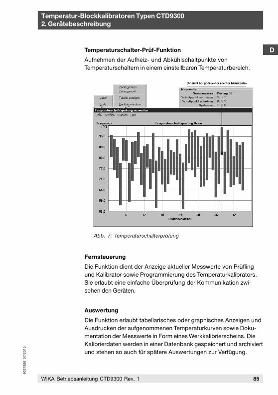
90
37
92
6 0
7/2
01
5
85WIKA Betriebsanleitung CTD9300 Rev. 1
Temperatur-Blockkalibratoren Typen CTD93002. Gerätebeschreibung
DTemperaturschalter-Prüf-Funktion
Aufnehmen der Aufheiz- und Abkühlschaltpunkte vonTemperaturschaltern in einem einstellbaren Temperaturbereich.
Fernsteuerung
Die Funktion dient der Anzeige aktueller Messwerte von Prüflingund Kalibrator sowie Programmierung des Temperaturkalibrators.Sie erlaubt eine einfache Überprüfung der Kommunikation zwi-schen den Geräten.
Auswertung
Die Funktion erlaubt tabellarisches oder graphisches Anzeigen undAusdrucken der aufgenommenen Temperaturkurven sowie Doku-mentation der Messwerte in Form eines Werkkalibrierscheins. DieKalibrierdaten werden in einer Datenbank gespeichert und archiviertund stehen so auch für spätere Auswertungen zur Verfügung.
Abb. 7: Temperaturschalterprüfung
90
37
92
6 0
7/2
01
5
86 WIKA Betriebsanleitung CTD9300 Rev. 1
Temperatur-Blockkalibratoren Typen CTD93002. Gerätebeschreibung
DD
2.5.5 DKD Kalibrierschein
Das DKD-Kalibrierzertifikat gibt dem Anwender Sicherheit, dass dieKalibrierergebnisse auf nationale Normale zurückgeführt sind unddie Messabweichungen angegebene Fehlergrenzen nicht über-schreiten.
DKD-Kalibrierungen sind optional zu allen Temperaturkalibratorenerhältlich. Sie sind ein Extra, dessen Preis sich nach der Anzahl dergeforderten Prüfpunkte richtet. DKD-Kalibrierungen werden beiTemperatur-Blockkalibratoren in der Regel bei 6 Prüftemperaturendurchgeführt. Die im DKD-Kalibrierschein angegebeneMessunsicherheit ist geräte- und temperaturabhängig.
Kalibrieren ist Vertrauenssache. Überlassen Sie deshalb Ihrewertvollen Geräte nur unserer kompetenten DKD-Kalibrierstelle, dienach der aktuellen Norm, z.Zt. DIN EN ISO/IEC 17025, akkreditiertist.
DKD-Labore unterliegen der regelmäßigen Überprüfung durch diePTB. Die Labormitarbeiter werden kontinuierlich geschult undweitergebildet. Durch regelmäßige Ringvergleiche wird nachgewie-sen, dass die bestätigten Mindestmessunsicherheiten tatsächlicheingehalten werden.
Systemanforderungen
IBM-kompatiblen PC ab 486 Prozessor mit Windows Betriebssys-tem 95, 98, NT 4.0, 9x, ME, 2000 u. XP und mindestens 64 MBArbeitsspeicher, CD-ROM-Laufwerk oder 3 ½" Floppy 1,44 MB,VGA Graphikkarte und Monitor, freie serielle Schnittstelle RS 232und Microsoft kompatible Maus
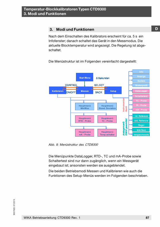
90
37
92
6 0
7/2
01
5
87WIKA Betriebsanleitung CTD9300 Rev. 1
Temperatur-Blockkalibratoren Typen CTD93003. Modi und Funktionen
D
Nach dem Einschalten des Kalibrators erscheint für ca. 5 s einInfofenster; danach schaltet das Gerät in den Messmodus. Dieaktuelle Blocktemperatur wird angezeigt. Die Regelung ist abge-schaltet.
Die Menüstruktur ist im Folgenden vereinfacht dargestellt:
Die Menüpunkte DataLogger, RTD-, TC und mA-Probe sowieSchaltertest sind nur dann zugänglich, wenn ein Messgeräteingebaut ist; ansonsten werden sie ausgeblendet.
Die beiden Betriebsmodi Messen und Kalibrieren wie auch dieFunktionen des Setup-Menüs werden im Folgenden beschrieben.
3. Modi und Funktionen
Abb. 8: Menüstruktur des CTD9300
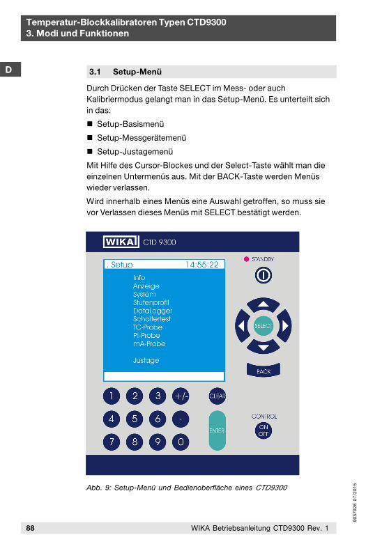
90
37
92
6 0
7/2
01
5
D
Temperatur-Blockkalibratoren Typen CTD93003. Modi und Funktionen
88 WIKA Betriebsanleitung CTD9300 Rev. 1
3.1 Setup-Menü
Durch Drücken der Taste SELECT im Mess- oder auchKalibriermodus gelangt man in das Setup-Menü. Es unterteilt sichin das:
Setup-Basismenü
Setup-Messgerätemenü
Setup-Justagemenü
Mit Hilfe des Cursor-Blockes und der Select-Taste wählt man dieeinzelnen Untermenüs aus. Mit der BACK-Taste werden Menüswieder verlassen.
Wird innerhalb eines Menüs eine Auswahl getroffen, so muss sievor Verlassen dieses Menüs mit SELECT bestätigt werden.
Abb. 9: Setup-Menü und Bedienoberfläche eines CTD9300
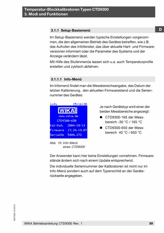
90
37
92
6 0
7/2
01
5
D
Temperatur-Blockkalibratoren Typen CTD93003. Modi und Funktionen
89WIKA Betriebsanleitung CTD9300 Rev. 1
3.1.1 Setup-Basismenü
Im Setup-Basismenü werden typische Einstellungen vorgenom-men, die den allgemeinen Betrieb des Gerätes betreffen, wie z.B.das Aufrufen des Infofenster, das über aktuelle Hart- und Firmware-versionen informiert oder die Parameter des Systems und derAnzeige verändern lässt.
Mit Hilfe des Stufenmenüs lassen sich u.a. auch Temperaturprofileerstellen und zyklisch abfahren.
3.1.1.1 Info-Menü
Im Infomenü findet man die Messbereichsangabe, das Datum derletzten Kalibrierung, den aktuellen Firmwarestand und die Serien-nummer des Gerätes:
Je nach Gerätetyp wird einer derbeiden Messbereiche angezeigt:
CTD9300-165 der Mess-bereich -30 °C / 165 °C
CTD9300-650 der Mess-bereich 40 °C / 650 °C
Der Anwender kann hier keine Einstellungen vornehmen. Firmware-stände ändern sich nach einem Update entsprechend.
Die individuelle Seriennummer der Kalibratoren ist nicht nur imInfo-Menü sondern auch auf dem Typenschild an der Geräte-rückseite angegeben.
Abb. 10: Info-Menüeines CTD9300
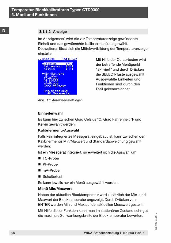
90
37
92
6 0
7/2
01
5
Temperatur-Blockkalibratoren Typen CTD93003. Modi und Funktionen
D
90 WIKA Betriebsanleitung CTD9300 Rev. 1
3.1.1.2 Anzeige
Im Anzeigemenü wird die zur Temperaturanzeige gewünschteEinheit und das gewünschte Kalibriermenü ausgewählt.Desweiteren lässt sich die Mittelwertbildung der Temperaturanzeigeeinstellen.
Mit Hilfe der Cursortasten wirdder betreffende Menüpunkt"aktiviert" und durch Drückendie SELECT-Taste ausgewählt.Ausgewählte Einheiten undFunktionen sind durch denPfeil gekennzeichnet.
Einheitenwahl
Es kann hier zwischen Grad Celsius °C, Grad Fahrenheit °F undKelvin gewählt werden.
Kalibriermenü-Auswahl
Falls kein integriertes Messgerät eingebaut ist, kann zwischen denKalibriermenüs Min/Maxwert und Standardabweichung gewähltwerden.
Ist ein Messgerät integriert, so erweitert sich die Auswahl um:
TC-Probe
Pt-Probe
mA-Probe
Schaltertest
Es kann jeweils nur ein Menü ausgewählt werden.
Menü Min/Maxwert
Neben der aktuellen Blocktemperatur wird zusätzlich der Min- undMaxwert der Blocktemperatur angezeigt. Durch Drücken vonENTER werden Min und Max auf den aktuellen Messwert gestellt.
Mit Hilfe dieser Funktion kann man im stationären Zustand sehr gutdie maximale Schwankungsbreite der Blocktemperatur bewerten.
Abb. 11: Anzeigeeinstellungen
90
37
92
6 0
7/2
01
5
Temperatur-Blockkalibratoren Typen CTD93003. Modi und Funktionen
D
91WIKA Betriebsanleitung CTD9300 Rev. 1
Menü Standardabweichung
Anstelle vom Min/Maxwert wird hier die Standardabweichung,d.h. der mittlere quadratische Fehler der Blocktemperatur über dieletzten n-Messwerte, angegeben. Durch Drücken von ENTER wirdn = 0 gesetzt und die Berechnung der Standardabweichungbeginnt von Neuem.
Menü Schaltertest
Prüfmenü für Temperaturschalter, siehe Abschnitt 3.1.2:Setup-Messgerätemenü
Menü TC-Probe
Kalibriermenü für Thermoelemente, siehe Abschnitt 3.1.2:Setup-Messgerätemenü
Menü Pt-Probe
Kalibriermenü für Widerstandsthermometer, siehe Abschnitt 3.1.2:Setup-Messgerätemenü
Menü mA-Probe
Kalibriermenü für Thermometer mit Temperaturtransmitter, sieheAbschnitt 3.1.2: Setup-Messgerätemenü
Anzeigenmittelung
Der von Gerät angezeigte Istwert der Blocktemperatur kann dermomentanen Temperatur entsprechen oder auch ein Mittelwertüber 2 bis 99 Messwerte sein. Der Mittelwert wird kontinuierlichnach der FIFO-Methode über die letzten n-Messwerte gebildet.Bei einer Messrate von ca. 4 Werten/s ergeben sich folgendeEinstellungen.
Anzahl der Mittelungen:
1, d.h. keine Mittelwertbildung
40, d.h. Mittelwertbildung über 10 s
99, d.h. Mittelwertbildung über 25 s
Wir empfehlen im Hinblick auf eine ruhige Anzeige eine Mittelungüber 50 Messwerte entsprechend einer Integrationszeit von 13 s.
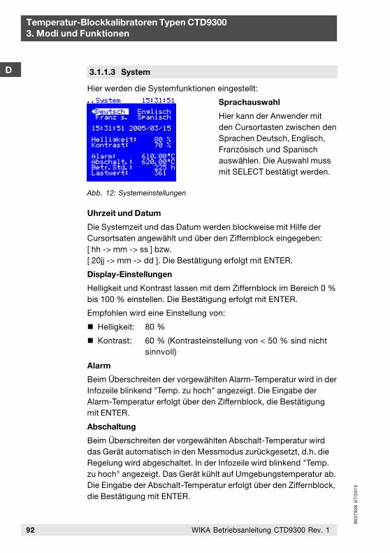
90
37
92
6 0
7/2
01
5
Temperatur-Blockkalibratoren Typen CTD93003. Modi und Funktionen
D
92 WIKA Betriebsanleitung CTD9300 Rev. 1
3.1.1.3 System
Hier werden die Systemfunktionen eingestellt:
Sprachauswahl
Hier kann der Anwender mitden Cursortasten zwischen denSprachen Deutsch, Englisch,Französisch und Spanischauswählen. Die Auswahl mussmit SELECT bestätigt werden.
Uhrzeit und Datum
Die Systemzeit und das Datum werden blockweise mit Hilfe derCursortsaten angewählt und über den Ziffernblock eingegeben:[ hh -> mm -> ss ] bzw.[ 20jj -> mm -> dd ]. Die Bestätigung erfolgt mit ENTER.
Display-Einstellungen
Helligkeit und Kontrast lassen mit dem Ziffernblock im Bereich 0 %bis 100 % einstellen. Die Bestätigung erfolgt mit ENTER.
Empfohlen wird eine Einstellung von:
Helligkeit: 80 %
Kontrast: 60 % (Kontrasteinstellung von < 50 % sind nichtsinnvoll)
Alarm
Beim Überschreiten der vorgewählten Alarm-Temperatur wird in derInfozeile blinkend "Temp. zu hoch" angezeigt. Die Eingabe derAlarm-Temperatur erfolgt über den Ziffernblock, die Bestätigungmit ENTER.
Abschaltung
Beim Überschreiten der vorgewählten Abschalt-Temperatur wirddas Gerät automatisch in den Messmodus zurückgesetzt, d.h. dieRegelung wird abgeschaltet. In der Infozeile wird blinkend "Temp.zu hoch" angezeigt. Das Gerät kühlt auf Umgebungstemperatur ab.Die Eingabe der Abschalt-Temperatur erfolgt über den Ziffernblock,die Bestätigung mit ENTER.
Abb. 12: Systemeinstellungen
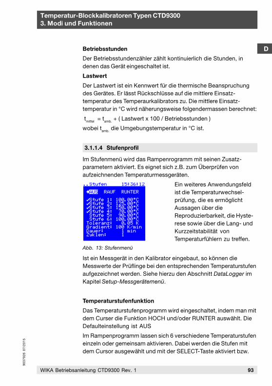
90
37
92
6 0
7/2
01
5
D
93WIKA Betriebsanleitung CTD9300 Rev. 1
Temperatur-Blockkalibratoren Typen CTD93003. Modi und Funktionen
Betriebsstunden
Der Betriebsstundenzähler zählt kontinuierlich die Stunden, indenen das Gerät eingeschaltet ist.
Lastwert
Der Lastwert ist ein Kennwert für die thermische Beanspruchungdes Gerätes. Er lässt Rückschlüsse auf die mittlere Einsatz-temperatur des Temperaurkalibrators zu. Die mittlere Einsatz-temperatur in °C wird näherungsweise folgendermassen berechnet:
tmittel = tamb. + ( Lastwert x 100 / Betriebsstunden )
wobei tamb. die Umgebungstemperatur in °C ist.
3.1.1.4 Stufenprofil
Im Stufenmenü wird das Rampenrogramm mit seinen Zusatz-parametern aktiviert. Es eignet sich z.B. zum Überprüfen vonaufzeichnenden Temperaturmessgeräten.
Ein weiteres Anwendungsfeldist die Temperaturwechsel-prüfung, die es ermöglichtAussagen über dieReproduzierbarkeit, die Hyste-rese sowie über die Lang- undKurzzeitstabilität vonTemperaturfühlern zu treffen.
Ist ein Messgerät in den Kalibrator eingebaut, so können dieMesswerte der Prüflinge bei den entsprechenden Temperaturstufenaufgezeichnet werden. Siehe hierzu den Abschnitt DataLogger imKapitel Setup-Messgerätemenü.
Temperaturstufenfunktion
Das Temperaturstufenprogramm wird eingeschaltet, indem man mitdem Curser die Funktion HOCH und/oder RUNTER auswählt. DieDefaulteinstellung ist AUS
Im Rampenprogramm lassen sich 6 verschiedene Temperaturstufeneinzeln oder gemeinsam aktivieren. Dabei werden die Stufen mitdem Cursor ausgewählt und mit der SELECT-Taste aktiviert bzw.
Abb. 13: Stufenmenü
90
37
92
6 0
7/2
01
5
Temperatur-Blockkalibratoren Typen CTD93003. Modi und Funktionen
D
94 WIKA Betriebsanleitung CTD9300 Rev. 1
deaktiviert. Jede einzelne Temperaturstufe kann innerhalb desArbeitsbereichs des Kalibrators auf jede beliebige Temperaturgestellt werden. Die Auflösung beträgt 0,01 K.
Die einzelnen Temperaturstufen sind von 1 bis 6 fortlaufendnummeriert. Ist die Funktion HOCH aktiviert, wird in der Reihenfol-ge Stufe 1, 2, 3, 4, 5 und 6 verfahren. Ist die Funktion RUNTERaktiviert, wird in der Reihenfolge Stufe 6, 5, 4, 3, 2 und 1 verfahren.Sind beide Funktionen aktiviert, so wird in der Reihenfolge 1, 2, 3,4, 5, 6, 5, 4, 3, 2 und 1 verfahren. Nichtaktive Stufen werdenübersprungen.
Gradientenfunktion
Mit Hilfe der Gradientenfunktion lässt sich ein definiertes Aufhei-zen und Abkühlen des Kalibrators einstellen. Der Wert für denGradienten wird in K/min mit einer Auflösung von 1 K eingestellt.
Die Obergrenze für den Gradienten ist durch die Heizleistung desbetreffenden Gerätes festgelegt. Das bedeutet, dass das Gerät mitaktivierter Gradientenfunktion nicht schneller aufheizen kann alsohne Funktion. Hauptanwendung für die Gradientenfunktion ist diePrüfung von Temperaturschaltern. Damit z.B. beim Aufheizen derSchaltpunkt eines Temperaturschalters nicht überfahren wird, heiztman den Kalibrator nur langsam auf. Typisch sind Gradientenzwischen 1 K/min und 5 K/min. Damit wird gerade bei Temperatur-schaltern mit größeren Tauchrohrdurchmessern verhindert, dassdie Temperatur des Schalter der des Kalibrators hinterherhinkt.
Toleranz und Dauer
Mit den Funktionen Toleranz und Dauer lassen sich Stabilität undLänge der Verweilzeit auf einer Temperaturstufe einstellen. Sollnach Erreichen der Solltemperatur mindestens 5 Minuten mit einerKonstanz von ±0,1 K verweilt werden, so werden die Dauer auf 5min und die Toleranz auf 0,1 K eingestellt. In diesem Fall läuft derTimer los, wenn die Isttemperatur um weniger als 0,1 K von derSolltemperatur abweicht. Bleibt die Temperatur nun für 5 mininnerhalb dieser Toleranz, wird nach Ablauf dieser Zeitspanne dienächste Stufe angesteuert. Treten während dieser Zeit Schwankun-gen auf, die die eingestellte Toleranz überschreiten, wird der Timerzurückgesetzt und neu gestartet.
90
37
92
6 0
7/2
01
5
D
Temperatur-Blockkalibratoren Typen CTD93003. Modi und Funktionen
95WIKA Betriebsanleitung CTD9300 Rev. 1
Das Erreichen der Toleranz wird durch STABIL in der Statuszeileangezeigt.
Die Toleranz lässt sich innerhalb der Grenzen von 0,01 K bis5,00 K einstellen, die Dauer im Bereich von 1 min bis 100 min.
Zyklen
Mit der Zyklen-Funktion können die Stufen kontinuierlich vomKalibrator gefahren werden. Sind z.B. die Temperaturstufen 1, 2und 3 aktiviert und ist die Funktion HOCH gewählt, dann werdendie Stufen 1, 2, und 3 entsprechend der eingestellten Zyklenhintereinander angefahren: bei einer Zyklenzahl von 3 entspre-chend 1, 2, 3, 1, 2, 3, 1, 2 und 3.
Sind die Funktionen HOCH und RUNTER beide gewählt, verfährtder Kalibrator folgendermaßen: 1, 2, 3, 2, 1, 2, 3, 2, 1, 2, 3, 2 und 1.
Diese Funktion ist besonders bei Temperaturwechselprüfungen anTemperaturfühlern hilfreich.
Ist die Temperaturstufenfunktion aktiv, so können keine Soll-werte über die Tastatatur vorgegeben werden. Die Tastaturbleibt solange gesperrt wie die Temperaturstufenfunktionaktiviert ist.
3.1.2 Setup-Messgerätemenü
Das Setup-Messgerätemenü steht nur dann zur Verfügung, wennein integriertes Messgerät im Kalibrator vorhanden ist. Das Menüdient der Konfiguration des DatenLoggers sowie der Kalibrierpro-zesse von Temperaturschaltern, Thermoelementen, Widerstands-thermometern und 4-20 mA-Temperaturtransmittern. Das Menü istausgeblendet, falls kein integriertes Messgerät vorhanden ist.
Das integrierbare Messgerät ermöglicht das Messen unterschiedli-cher Sensorsignale sowie deren Umwandlung in Grad C nachgenormten Kennlinien. Das Detektieren von Schaltpunkten beiTemperaturschaltern ist ebenfalls möglich. Mit der Datenlogger-funktion lassen sich bis zu sechs Prüflingstemperaturen sowie dievom Kalibrator vorgegebene Solltemperatur pro Prüfling speichern.Insgesamt können die Kalibrierdaten vom bis zu acht Prüflingenaufgezeichnet werden.
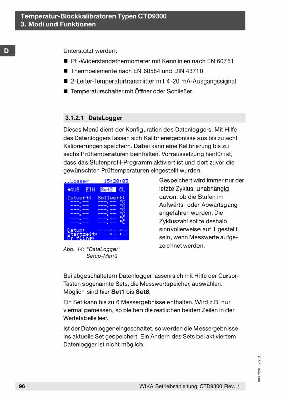
90
37
92
6 0
7/2
01
5
3.1.2.1 DataLogger
Unterstützt werden:
Pt -Widerstandsthermometer mit Kennlinien nach EN 60751
Thermoelemente nach EN 60584 und DIN 43710
2-Leiter-Temperaturtransmitter mit 4-20 mA-Ausgangssignal
Temperaturschalter mit Öffner oder Schließer.
Temperatur-Blockkalibratoren Typen CTD93003. Modi und Funktionen
D
96 WIKA Betriebsanleitung CTD9300 Rev. 1
Dieses Menü dient der Konfiguration des Datenloggers. Mit Hilfedes Datenloggers lassen sich Kalibrierergebnisse aus bis zu achtKalibrierungen speichern. Dabei kann eine Kalibrierung bis zusechs Prüftemperaturen beinhalten. Vorraussetzung hierfür ist,dass das Stufenprofil-Programm aktiviert ist und dort zuvor diegewünschten Prüftemperaturen eingestellt wurden.
Gespeichert wird immer nur derletzte Zyklus, unabhängigdavon, ob die Stufen imAufwärts- oder Abwärtsgangangefahren wurden. DieZykluszahl sollte deshalbsinnvollerweise auf 1 gestelltsein, wenn Messwerte aufge-zeichnet werden.
Bei abgeschaltetem Datenlogger lassen sich mit Hilfe der Cursor-Tasten sogenannte Sets, die Messwertspeicher, auswählen.Möglich sind hier Set1 bis Set8.
Ein Set kann bis zu 6 Messergebnisse enthalten. Wird z.B. nurviermal gemessen, so bleiben die restlichen beiden Zeilen in derWertetabelle leer.
Ist der Datenlogger eingeschaltet, so werden die Messergebnisseins aktuelle Set gespeichert. Ein Ändern des Sets bei aktiviertemDatenlogger ist nicht möglich.
Abb. 14: "DataLogger"Setup-Menü
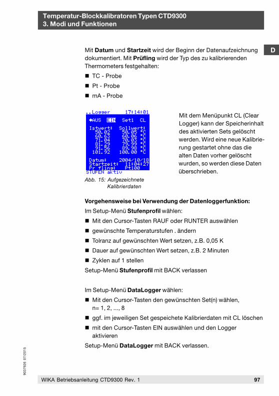
90
37
92
6 0
7/2
01
5
Temperatur-Blockkalibratoren Typen CTD93003. Modi und Funktionen
D
97WIKA Betriebsanleitung CTD9300 Rev. 1
Mit Datum und Startzeit wird der Beginn der Datenaufzeichnungdokumentiert. Mit Prüfling wird der Typ des zu kalibrierendenThermometers festgehalten:
TC - Probe
Pt - Probe
mA - Probe
Mit dem Menüpunkt CL (ClearLogger) kann der Speicherinhaltdes aktivierten Sets gelöschtwerden. Wird eine neue Kalibrie-rung gestartet ohne das diealten Daten vorher gelöschtwurden, so werden diese Datenüberschrieben.
Vorgehensweise bei Verwendung der Datenloggerfunktion:
Im Setup-Menü Stufenprofil wählen:
Mit den Cursor-Tasten RAUF oder RUNTER auswählen
gewünschte Temperaturstufen . ändern
Tolranz auf gewünschten Wert setzen, z.B. 0,05 K
Dauer auf gewünschten Wert setzen, z.B. 2 Minuten
Zyklen auf 1 stellen
Setup-Menü Stufenprofil mit BACK verlassen
Im Setup-Menü DataLogger wählen:
Mit den Cursor-Tasten den gewünschten Set(n) wählen,n= 1, 2, ..., 8
ggf. im jeweiligen Set gespeichete Kalibrierdaten mit CL löschen
mit den Cursor-Tasten EIN auswählen und den Loggeraktivieren
Setup-Menü DataLogger mit BACK verlassen.
Abb. 15: AufgezeichneteKalibrierdaten
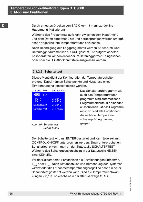
90
37
92
6 0
7/2
01
5
Temperatur-Blockkalibratoren Typen CTD93003. Modi und Funktionen
D
98 WIKA Betriebsanleitung CTD9300 Rev. 1
Durch erneutes Drücken von BACK kommt mann zurück insHauptmenü (Kalibrieren)
Während des Progammablaufs kann zwischen dem Hauptmenüund dem Datenloggermenü hin und hergesprungen werden um ggf.schon abgearbeitete Temperaturstufen anzusehen.
Nach Beendigung des Loggprogramms werden Stufenprofil undDatenlogger automatisch auf AUS gesetzt. Die aufgezeichnetenKalibrierdaten können entweder im Datenloggermenü eingesehenoder über die RS 232-Schnittstelle ausgelesen werden.
Dieses Menü dient der Konfiguration der Temperaturschalter-prüfung. Dabei können Schaltpunkte und Hysterese einesTemperaturschalters festgestellt werden.
Das Schalterprüfprogramm wieauch das Temperaturstufen-programm sind automatischeProgrammabläufe, die einanderausschließen. Ist das Programmaktiv, so sind alle Funktionen,die nicht der Temperatur-schalterprüfung dienen,gesperrt.
Der Schaltertest wird mit ENTER gestartet und kann jederzeit mitCONTROL ON/OFF unterbrochen werden. Einen unterbrochenenSchaltertest erkennt man an der Statuszeile SCHALTERTEST.Während des Schaltertests erscheint in der Statuszeile HEIZENbzw. KÜHLEN.
Vor der Solltemperatur erscheinen die Bezeichnungen Entnahme,T
max oder Tmin. Nach Testabschluss und Berechnung der Hysteresewird wieder die Entnahmetemperatur angeregelt so dass ein neuerSchaltertest gestartet werden kann. Sind die Temperaturschwan-kungen < 0,1 K, so erscheint in der Statusanzeige STABIL.
3.1.2.2 Schaltertest
Abb. 16: SchaltertestSetup-Menü
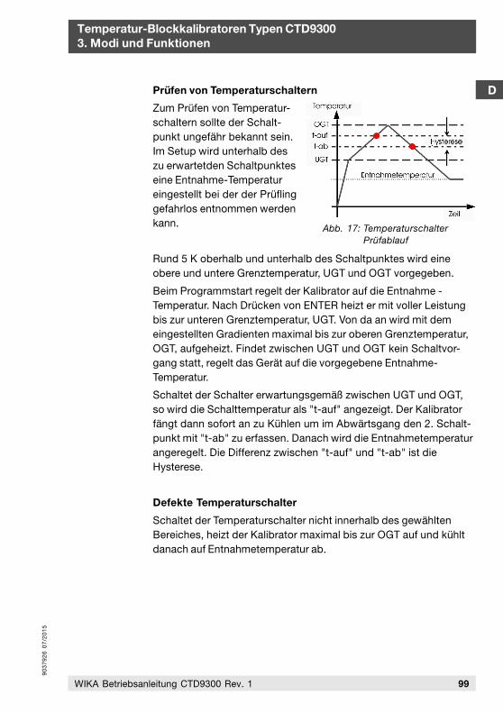
90
37
92
6 0
7/2
01
5
Temperatur-Blockkalibratoren Typen CTD93003. Modi und Funktionen
D
99WIKA Betriebsanleitung CTD9300 Rev. 1
Prüfen von Temperaturschaltern
Zum Prüfen von Temperatur-schaltern sollte der Schalt-punkt ungefähr bekannt sein.Im Setup wird unterhalb deszu erwartetden Schaltpunkteseine Entnahme-Temperatureingestellt bei der der Prüflinggefahrlos entnommen werdenkann.
Rund 5 K oberhalb und unterhalb des Schaltpunktes wird eineobere und untere Grenztemperatur, UGT und OGT vorgegeben.
Beim Programmstart regelt der Kalibrator auf die Entnahme -Temperatur. Nach Drücken von ENTER heizt er mit voller Leistungbis zur unteren Grenztemperatur, UGT. Von da an wird mit demeingestellten Gradienten maximal bis zur oberen Grenztemperatur,OGT, aufgeheizt. Findet zwischen UGT und OGT kein Schaltvor-gang statt, regelt das Gerät auf die vorgegebene Entnahme-Temperatur.
Schaltet der Schalter erwartungsgemäß zwischen UGT und OGT,so wird die Schalttemperatur als "t-auf" angezeigt. Der Kalibratorfängt dann sofort an zu Kühlen um im Abwärtsgang den 2. Schalt-punkt mit "t-ab" zu erfassen. Danach wird die Entnahmetemperaturangeregelt. Die Differenz zwischen "t-auf" und "t-ab" ist dieHysterese.
Defekte Temperaturschalter
Schaltet der Temperaturschalter nicht innerhalb des gewähltenBereiches, heizt der Kalibrator maximal bis zur OGT auf und kühltdanach auf Entnahmetemperatur ab.
Abb. 17: TemperaturschalterPrüfablauf
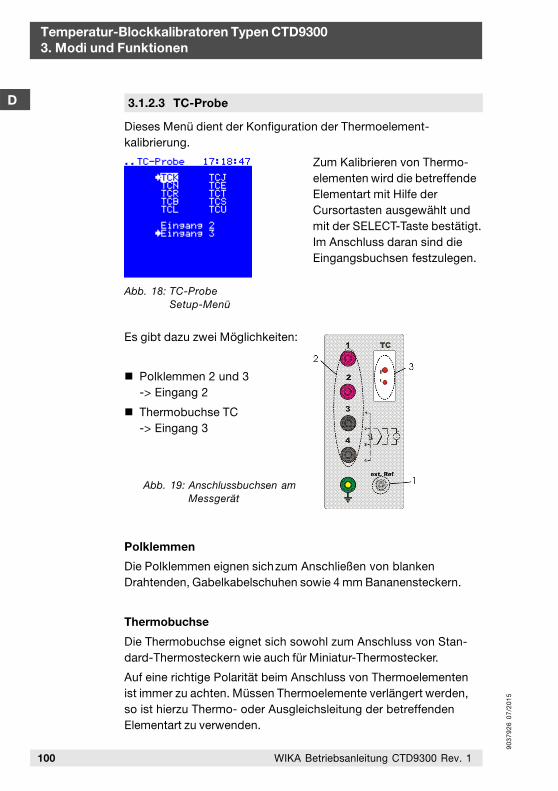
90
37
92
6 0
7/2
01
5
Dieses Menü dient der Konfiguration der Thermoelement-kalibrierung.
Zum Kalibrieren von Thermo-elementen wird die betreffendeElementart mit Hilfe derCursortasten ausgewählt undmit der SELECT-Taste bestätigt.Im Anschluss daran sind dieEingangsbuchsen festzulegen.
Es gibt dazu zwei Möglichkeiten:
Polklemmen 2 und 3-> Eingang 2
Thermobuchse TC-> Eingang 3
Polklemmen
Die Polklemmen eignen sichzum Anschließen von blankenDrahtenden, Gabelkabelschuhen sowie 4 mm Bananensteckern.
Thermobuchse
Die Thermobuchse eignet sich sowohl zum Anschluss von Stan-dard-Thermosteckern wie auch für Miniatur-Thermostecker.
Auf eine richtige Polarität beim Anschluss von Thermoelementenist immer zu achten. Müssen Thermoelemente verlängert werden,so ist hierzu Thermo- oder Ausgleichsleitung der betreffendenElementart zu verwenden.
Temperatur-Blockkalibratoren Typen CTD93003. Modi und Funktionen
D
100 WIKA Betriebsanleitung CTD9300 Rev. 1
3.1.2.3 TC-Probe
Abb. 18: TC-ProbeSetup-Menü
Abb. 19: Anschlussbuchsen amMessgerät
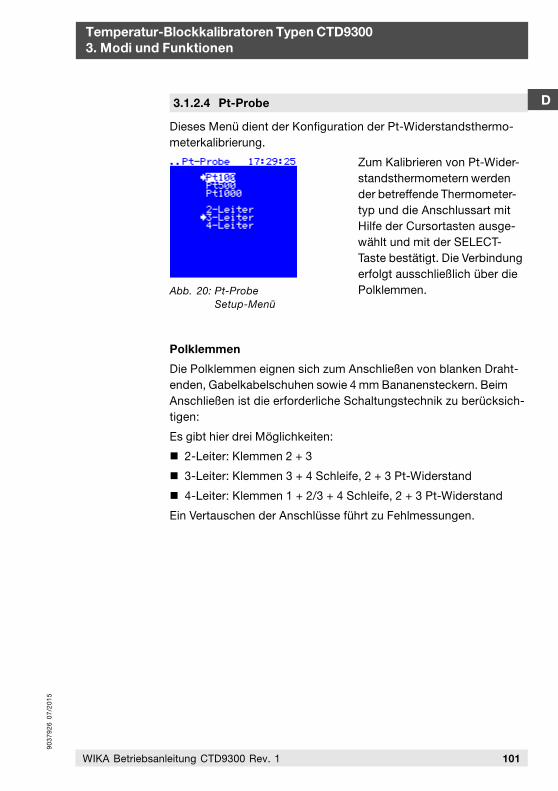
90
37
92
6 0
7/2
01
5
3.1.2.4 Pt-Probe D
Temperatur-Blockkalibratoren Typen CTD93003. Modi und Funktionen
101WIKA Betriebsanleitung CTD9300 Rev. 1
Dieses Menü dient der Konfiguration der Pt-Widerstandsthermo-meterkalibrierung.
Zum Kalibrieren von Pt-Wider-standsthermometern werdender betreffende Thermometer-typ und die Anschlussart mitHilfe der Cursortasten ausge-wählt und mit der SELECT-Taste bestätigt. Die Verbindungerfolgt ausschließlich über diePolklemmen.
Polklemmen
Die Polklemmen eignen sich zum Anschließen von blanken Draht-enden, Gabelkabelschuhen sowie 4 mm Bananensteckern. BeimAnschließen ist die erforderliche Schaltungstechnik zu berücksich-tigen:
Es gibt hier drei Möglichkeiten:
2-Leiter: Klemmen 2 + 3
3-Leiter: Klemmen 3 + 4 Schleife, 2 + 3 Pt-Widerstand
4-Leiter: Klemmen 1 + 2/3 + 4 Schleife, 2 + 3 Pt-Widerstand
Ein Vertauschen der Anschlüsse führt zu Fehlmessungen.
Abb. 20: Pt-ProbeSetup-Menü
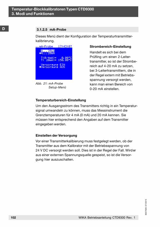
90
37
92
6 0
7/2
01
5
102 WIKA Betriebsanleitung CTD9300 Rev. 1
Temperatur-Blockkalibratoren Typen CTD93003. Modi und Funktionen
D
Dieses Menü dient der Konfiguration der Temperaturtransmitter-kalibrierung.
Strombereich-Einstellung
Handelt es sich bei demPrüfling um einen 2-Leiter-transmitter, so ist der Strombe-reich auf 4-20 mA zu setzen,bei 3-Leitertransmittern, die inder Regel extern mit Betriebs-spannung versorgt werden,kann man einen Bereich von0-20 mA einstellen.
Temperaturbereich-Einstellung
Um den Ausgangsstrom des Transmitters richtig in ein Temperatur-signal umwandeln zu können, muss das Messinstrument dieGrenztemperaturen für 4 mA (0 mA) und 20 mA kennen. Siemüssen hier entsprechend den Angaben auf dem Transmittereingegeben werden.
Einstellen der Versorgung
Vor einer Transmitterkalibierung muss festgelegt werden, ob derTransmitter aus dem Kalibrator mit der Betriebsspannung von24 V DC versorgt werden soll. Dies ist in der Regel der Fall. Wirderaus einer externen Spannungsquelle gespeist, so ist die Versor-gung hier auszuschalten.
3.1.2.5 mA-Probe
Abb. 21: mA-ProbeSetup-Menü
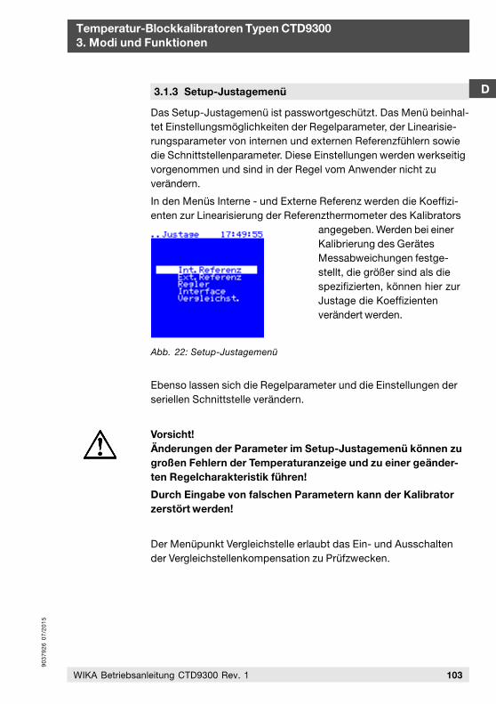
90
37
92
6 0
7/2
01
5
3.1.3 Setup-Justagemenü
103WIKA Betriebsanleitung CTD9300 Rev. 1
D
Temperatur-Blockkalibratoren Typen CTD93003. Modi und Funktionen
Das Setup-Justagemenü ist passwortgeschützt. Das Menü beinhal-tet Einstellungsmöglichkeiten der Regelparameter, der Linearisie-rungsparameter von internen und externen Referenzfühlern sowiedie Schnittstellenparameter. Diese Einstellungen werden werkseitigvorgenommen und sind in der Regel vom Anwender nicht zuverändern.
In den Menüs Interne - und Externe Referenz werden die Koeffizi-enten zur Linearisierung der Referenzthermometer des Kalibrators
angegeben. Werden bei einerKalibrierung des GerätesMessabweichungen festge-stellt, die größer sind als diespezifizierten, können hier zurJustage die Koeffizientenverändert werden.
Ebenso lassen sich die Regelparameter und die Einstellungen derseriellen Schnittstelle verändern.
Vorsicht!Änderungen der Parameter im Setup-Justagemenü können zugroßen Fehlern der Temperaturanzeige und zu einer geänder-ten Regelcharakteristik führen!
Durch Eingabe von falschen Parametern kann der Kalibratorzerstört werden!
Der Menüpunkt Vergleichstelle erlaubt das Ein- und Ausschaltender Vergleichstellenkompensation zu Prüfzwecken.
Abb. 22: Setup-Justagemenü
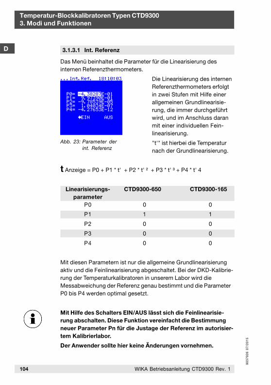
90
37
92
6 0
7/2
01
5
104 WIKA Betriebsanleitung CTD9300 Rev. 1
Temperatur-Blockkalibratoren Typen CTD93003. Modi und Funktionen
D
Das Menü beinhaltet die Parameter für die Linearisierung desinternen Referenzthermometers.
Die Linearisierung des internenReferenzthermometers erfolgtin zwei Stufen mit Hilfe einerallgemeinen Grundlinearisie-rung, die immer durchgeführtwird, und im Anschluss daranmit einer individuellen Fein-linearisierung.
"t'" ist hierbei die Temperaturnach der Grundlinearisierung.
t Anzeige = P0 + P1 * t' + P2 * t' ² + P3 * t' ³ + P4 * t' 4
Linearisierungs- CTD9300-650 CTD9300-165parameter
P0 0 0
P1 1 1
P2 0 0
P3 0 0
P4 0 0
Mit diesen Parametern ist nur die allgemeine Grundlinearisierungaktiv und die Feinlinearisierung abgeschaltet. Bei der DKD-Kalibrie-rung der Temperaturkalibratoren in unserem Labor wird dieMessabweichung der Referenz genau bestimmt und die ParameterP0 bis P4 werden optimal gesetzt.
Mit Hilfe des Schalters EIN/AUS lässt sich die Feinlinearisie-rung abschalten. Diese Funktion vereinfacht die Bestimmungneuer Parameter Pn für die Justage der Referenz im autorisier-tem Kalibrierlabor.
Der Anwender sollte hier keine Änderungen vornehmen.
3.1.3.1 Int. Referenz
Abb. 23: Parameter derint. Referenz
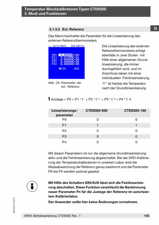
90
37
92
6 0
7/2
01
5
3.1.3.2 Ext. Referenz
105WIKA Betriebsanleitung CTD9300 Rev. 1
D
Temperatur-Blockkalibratoren Typen CTD93003. Modi und Funktionen
Abb. 24: Parameter derext. Referenz
Das Menü beinhaltet die Parameter für die Linearisierung desexternen Referenzthermometers.
Die Linearisierung des externenReferezthermometers erfolgtebenfalls in zwei Stufen mitHilfe einer allgemeinen Grund-linearisierung, die immerdurchgeführt wird, und imAnschluss daran mit einerindividuellen Feinlinearisierung.
"t'" ist hierbei die Temperaturnach der Grundlinearisierung
t Anzeige = P0 + P1 * t' + P2 * t' ² + P3 * t' ³ + P4 * t' 4
Linearisierungs- CTD9300-650 CTD9300-165parameter
P0 0 0
P1 1 1
P2 0 0
P3 0 0
P4 0 0
Mit diesen Parametern ist nur die allgemeine Grundlinearisierungaktiv und die Feinlinearisierung abgeschaltet. Bei der DKD-Kalibrie-rung der Temperaturkalibratoren in unserem Labor wird dieMessabweichung der Referenz genau bestimmt und die ParameterP0 bis P4 werden optimal gesetzt.
Mit Hilfe des Schalters EIN/AUS lässt sich die Feinlinearisie-rung abschalten. Diese Funktion vereinfacht die Bestimmungneuer Parameter Pn für die Justage der Referenz im autorisier-tem Kalibrierlabor.
Der Anwender sollte hier keine Änderungen vornehmen.
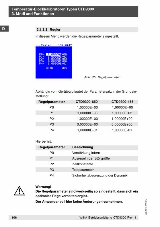
90
37
92
6 0
7/2
01
5
106 WIKA Betriebsanleitung CTD9300 Rev. 1
Temperatur-Blockkalibratoren Typen CTD93003. Modi und Funktionen
D
In diesem Menü werden die Regelparameter eingestellt.
3.1.3.3 Regler
Abb. 25: Regelparameter
Abhängig vom Gerätetyp lautet der Parametersatz in der Grundein-stellung:
Regelparameter CTD9300-650
P0 1,00000E+00
P1 1,00000E-03
P2 1,00000E+00
P3 0,00000E+00
P4 1,00000E-01
CTD9300-165
1,00000E+00
1,00000E-02
1,00000E+00
0,00000E+00
1,00000E-01
Hierbei ist:
Regelparameter Bezeichnung
P0 Verstärkung intern
P1 Ausregeln der Störgröße
P2 Zeitkonstante
P3 Testparameter
P4 Sicherheitsbegrenzung der Dynamik
Warnung!Die Regelparameter sind werkseitig so eingestellt, dass sich einoptimales Regelverhalten ergibt.
Der Anwender soll hier keine Änderungen vornehmen.

90
37
92
6 0
7/2
01
5
3.1.3.4 Interface
107WIKA Betriebsanleitung CTD9300 Rev. 1
D
Temperatur-Blockkalibratoren Typen CTD93003. Modi und Funktionen
Im Interfacemenü werden die Baudrate für die Datenübertragungüber die RS 232-Schnittstelle sowie das zu verwendende Protokolleingestellt.
Baudrate
Unterstützt werden hier 2400Baud, 4800 Baud und 9600Baud. Sie werden mit denCursor-Tasten gewählt und mitder SELECT-Taste aktiviert.
Protokoll
Grundeinstellung ist das Standard-Protokoll, das immer danneingestellt sein muss, wenn die Kalibratoren zusammen mit unsererSoftware betrieben werden. Insgesamt sind folgende Einstellungenmöglich:
Standard: Standardprotokoll
Test: werksinternes Testprotokoll
Display: werksinternes Testprotokoll
Die Protokolle werden mit den Cursor-Tasten ausgegewählt undmit der SELECT-Taste aktiviert.
Parität
Hier wird die Parität eingestellt. Default-Einstellung ist "no".Weitere Einstellungen sind mit "even" und "odd" möglich.
Abb. 26: Interface Parameter
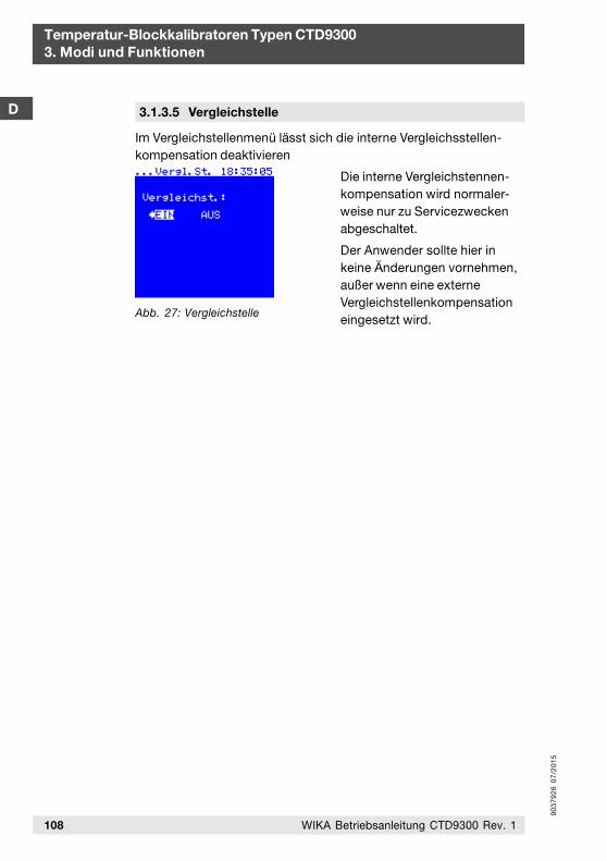
90
37
92
6 0
7/2
01
5
108 WIKA Betriebsanleitung CTD9300 Rev. 1
Temperatur-Blockkalibratoren Typen CTD93003. Modi und Funktionen
D
Abb. 27: Vergleichstelle
3.1.3.5 Vergleichstelle
Im Vergleichstellenmenü lässt sich die interne Vergleichsstellen-kompensation deaktivieren
Die interne Vergleichstennen-kompensation wird normaler-weise nur zu Servicezweckenabgeschaltet.
Der Anwender sollte hier inkeine Änderungen vornehmen,außer wenn eine externeVergleichstellenkompensationeingesetzt wird.
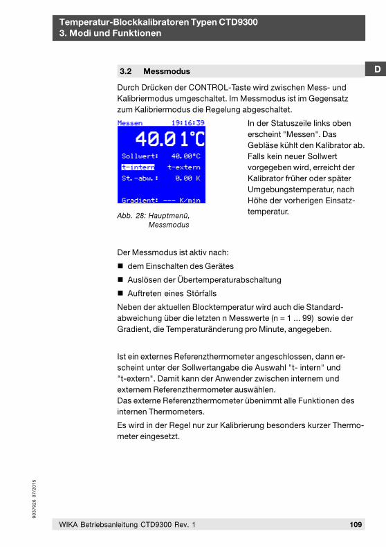
90
37
92
6 0
7/2
01
5
109WIKA Betriebsanleitung CTD9300 Rev. 1
D
Temperatur-Blockkalibratoren Typen CTD93003. Modi und Funktionen
Durch Drücken der CONTROL-Taste wird zwischen Mess- undKalibriermodus umgeschaltet. Im Messmodus ist im Gegensatzzum Kalibriermodus die Regelung abgeschaltet.
In der Statuszeile links obenerscheint "Messen". DasGebläse kühlt den Kalibrator ab.Falls kein neuer Sollwertvorgegeben wird, erreicht derKalibrator früher oder späterUmgebungstemperatur, nachHöhe der vorherigen Einsatz-temperatur.
Der Messmodus ist aktiv nach:
dem Einschalten des Gerätes
Auslösen der Übertemperaturabschaltung
Auftreten eines Störfalls
Neben der aktuellen Blocktemperatur wird auch die Standard-abweichung über die letzten n Messwerte (n = 1 ... 99) sowie derGradient, die Temperaturänderung pro Minute, angegeben.
Ist ein externes Referenzthermometer angeschlossen, dann er-scheint unter der Sollwertangabe die Auswahl "t- intern" und"t-extern". Damit kann der Anwender zwischen internem undexternem Referenzthermometer auswählen.Das externe Referenzthermometer übenimmt alle Funktionen desinternen Thermometers.
Es wird in der Regel nur zur Kalibrierung besonders kurzer Thermo-meter eingesetzt.
3.2 Messmodus
Abb. 28: Hauptmenü,Messmodus
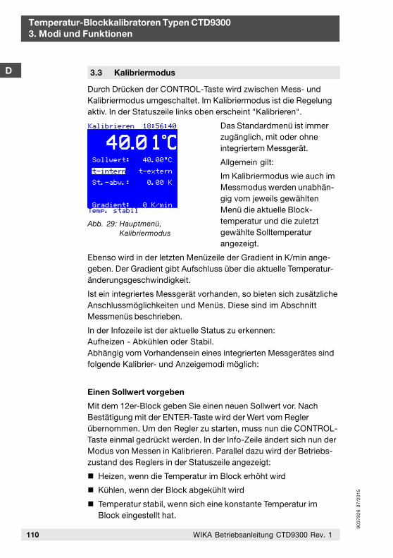
90
37
92
6 0
7/2
01
5
Temperatur-Blockkalibratoren Typen CTD93003. Modi und Funktionen
D
110 WIKA Betriebsanleitung CTD9300 Rev. 1
Durch Drücken der CONTROL-Taste wird zwischen Mess- undKalibriermodus umgeschaltet. Im Kalibriermodus ist die Regelungaktiv. In der Statuszeile links oben erscheint "Kalibrieren".
Das Standardmenü ist immerzugänglich, mit oder ohneintegriertem Messgerät.
Allgemein gilt:
Im Kalibriermodus wie auch imMessmodus werden unabhän-gig vom jeweils gewähltenMenü die aktuelle Block-temperatur und die zuletztgewählte Solltemperaturangezeigt.
Ebenso wird in der letzten Menüzeile der Gradient in K/min ange-geben. Der Gradient gibt Aufschluss über die aktuelle Temperatur-änderungsgeschwindigkeit.
Ist ein integriertes Messgerät vorhanden, so bieten sich zusätzlicheAnschlussmöglichkeiten und Menüs. Diese sind im AbschnittMessmenüs beschrieben.
In der Infozeile ist der aktuelle Status zu erkennen:Aufheizen - Abkühlen oder Stabil.Abhängig vom Vorhandensein eines integrierten Messgerätes sindfolgende Kalibrier- und Anzeigemodi möglich:
Einen Sollwert vorgeben
Mit dem 12er-Block geben Sie einen neuen Sollwert vor. NachBestätigung mit der ENTER-Taste wird der Wert vom Reglerübernommen. Um den Regler zu starten, muss nun die CONTROL-Taste einmal gedrückt werden. In der Info-Zeile ändert sich nun derModus von Messen in Kalibrieren. Parallel dazu wird der Betriebs-zustand des Reglers in der Statuszeile angezeigt:
Heizen, wenn die Temperatur im Block erhöht wird
Kühlen, wenn der Block abgekühlt wird
Temperatur stabil, wenn sich eine konstante Temperatur imBlock eingestellt hat.
3.3 Kalibriermodus
Abb. 29: Hauptmenü,Kalibriermodus
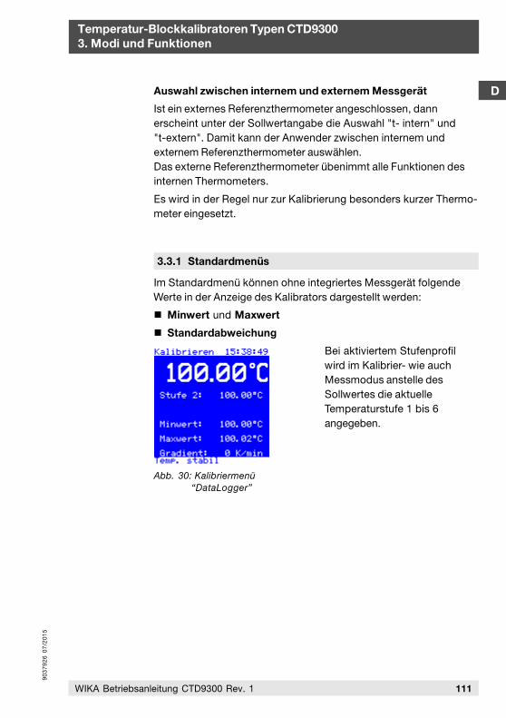
90
37
92
6 0
7/2
01
5
D
Temperatur-Blockkalibratoren Typen CTD93003. Modi und Funktionen
111WIKA Betriebsanleitung CTD9300 Rev. 1
Im Standardmenü können ohne integriertes Messgerät folgendeWerte in der Anzeige des Kalibrators dargestellt werden:
Minwert und Maxwert
Standardabweichung
Bei aktiviertem Stufenprofilwird im Kalibrier- wie auchMessmodus anstelle desSollwertes die aktuelleTemperaturstufe 1 bis 6angegeben.
3.3.1 Standardmenüs
Auswahl zwischen internem und externem Messgerät
Ist ein externes Referenzthermometer angeschlossen, dannerscheint unter der Sollwertangabe die Auswahl "t- intern" und"t-extern". Damit kann der Anwender zwischen internem undexternem Referenzthermometer auswählen.Das externe Referenzthermometer übenimmt alle Funktionen desinternen Thermometers.
Es wird in der Regel nur zur Kalibrierung besonders kurzer Thermo-meter eingesetzt.
Abb. 30: Kalibriermenü“DataLogger”
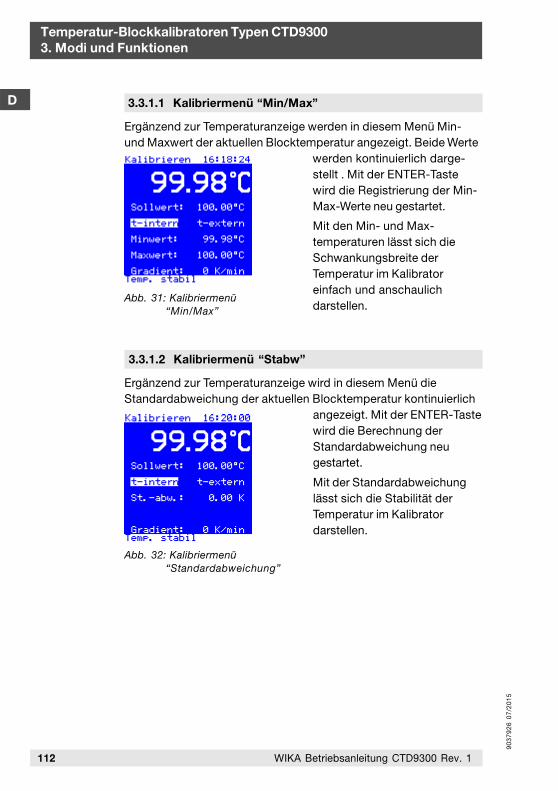
90
37
92
6 0
7/2
01
5
Temperatur-Blockkalibratoren Typen CTD93003. Modi und Funktionen
D
112 WIKA Betriebsanleitung CTD9300 Rev. 1
Abb. 32: Kalibriermenü“Standardabweichung”
Ergänzend zur Temperaturanzeige wird in diesem Menü dieStandardabweichung der aktuellen Blocktemperatur kontinuierlich
angezeigt. Mit der ENTER-Tastewird die Berechnung derStandardabweichung neugestartet.
Mit der Standardabweichunglässt sich die Stabilität derTemperatur im Kalibratordarstellen.
3.3.1.2 Kalibriermenü “Stabw”
Abb. 31: Kalibriermenü“Min/Max”
Ergänzend zur Temperaturanzeige werden in diesem Menü Min-und Maxwert der aktuellen Blocktemperatur angezeigt. Beide Werte
werden kontinuierlich darge-stellt . Mit der ENTER-Tastewird die Registrierung der Min-Max-Werte neu gestartet.
Mit den Min- und Max-temperaturen lässt sich dieSchwankungsbreite derTemperatur im Kalibratoreinfach und anschaulichdarstellen.
3.3.1.1 Kalibriermenü “Min/Max”

90
37
92
6 0
7/2
01
5
Wenn der Kalibrator ein integriertes Messgerät besitzt, steht zu-sätzlich zum Standardmenü ein Messgerätemenü zur Verfügung.Dies beinhaltet die Funktionen:
Temperaturschaltertest
Thermoelementkalibrierung
Pt-Widerstandsthermometerkalibrierung
4-20 mA Transmitterkalibrierung
Die Auswahl zwischen externen und internen Rreferenzthermo-meter wird nur angeboten wenn ein externes Referenzthermometerangeschlossen ist.
Die Abweichung des Prüflings wird entweder im Vergleich zurinternen oder externen Referenz angegeben, je nach dem, welcheder beiden Referenzen aktiviert ist.
Bei aktiviertem Stufenprofilsowie bei der DataLogger-Funktion wird im Kalibrier- wieauch Messmodus anstelle desSollwertes die aktuelleTemperraturstufe 1 bis 6angegeben.
3.3.2 Messgerätemenüs D
Temperatur-Blockkalibratoren Typen CTD93003. Modi und Funktionen
113WIKA Betriebsanleitung CTD9300 Rev. 1
In diesem Menü lassen sichzusätzlich zur Soll- undIsttemperatur des Kalibratorsdie Ausgangsgrößen einesTemperaturschalters anzeigen.
3.3.2.1 Kalibriermenü “Schaltertest”
Abb. 34: Kalibriermenü“Schaltertest”
Abb. 33: Kalibriermenü“DataLogger”
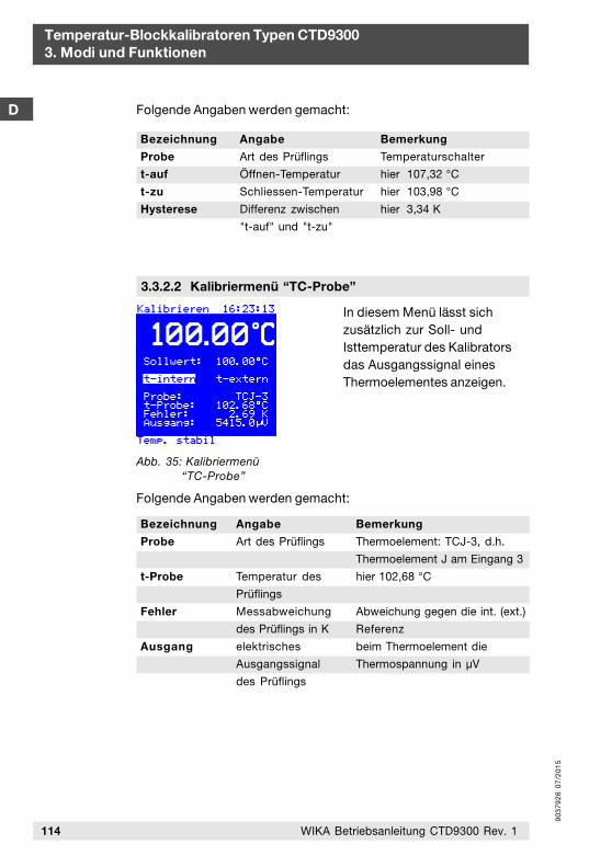
90
37
92
6 0
7/2
01
5
Temperatur-Blockkalibratoren Typen CTD93003. Modi und Funktionen
D
114 WIKA Betriebsanleitung CTD9300 Rev. 1
In diesem Menü lässt sichzusätzlich zur Soll- undIsttemperatur des Kalibratorsdas Ausgangssignal einesThermoelementes anzeigen.
3.3.2.2 Kalibriermenü “TC-Probe”
Abb. 35: Kalibriermenü“TC-Probe”
Bemerkung
Thermoelement: TCJ-3, d.h.
Thermoelement J am Eingang 3
hier 102,68 °C
Abweichung gegen die int. (ext.)
Referenz
beim Thermoelement die
Thermospannung in µV
Bezeichnung
Probe
t-Probe
Fehler
Ausgang
Angabe
Art des Prüflings
Temperatur des
Prüflings
Messabweichung
des Prüflings in K
elektrisches
Ausgangssignal
des Prüflings
Bemerkung
Temperaturschalter
hier 107,32 °C
hier 103,98 °C
hier 3,34 K
Angabe
Art des Prüflings
Öffnen-Temperatur
Schliessen-Temperatur
Differenz zwischen
"t-auf" und "t-zu"
Bezeichnung
Probe
t-auf
t-zu
Hysterese
Folgende Angaben werden gemacht:
Folgende Angaben werden gemacht:
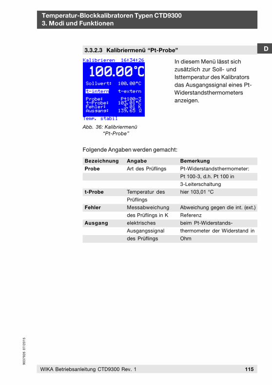
90
37
92
6 0
7/2
01
5
D
Temperatur-Blockkalibratoren Typen CTD93003. Modi und Funktionen
115WIKA Betriebsanleitung CTD9300 Rev. 1
In diesem Menü lässt sichzusätzlich zur Soll- undIsttemperatur des Kalibratorsdas Ausgangssignal eines Pt-Widerstandsthermometersanzeigen.
3.3.2.3 Kalibriermenü “Pt-Probe”
Abb. 36: Kalibriermenü“Pt-Probe”
Bemerkung
Pt-Widerstandsthermometer:
Pt 100-3, d.h. Pt 100 in
3-Leiterschaltung
hier 103,01 °C
Abweichung gegen die int. (ext.)
Referenz
beim Pt-Widerstands-
thermometer der Widerstand in
Ohm
Bezeichnung
Probe
t-Probe
Fehler
Ausgang
Angabe
Art des Prüflings
Temperatur des
Prüflings
Messabweichung
des Prüflings in K
elektrisches
Ausgangssignal
des Prüflings
Folgende Angaben werden gemacht:
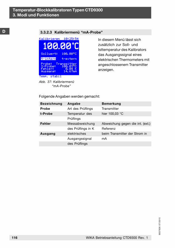
90
37
92
6 0
7/2
01
5
Temperatur-Blockkalibratoren Typen CTD93003. Modi und Funktionen
D
116 WIKA Betriebsanleitung CTD9300 Rev. 1
In diesem Menü lässt sichzusätzlich zur Soll- undIsttemperatur des Kalibratorsdas Ausgangssignal eineselektrischen Thermometers mitangeschlossenem Transmitteranzeigen.
3.3.2.3 Kalibriermenü “mA-Probe”
Abb. 37: Kalibriermenü“mA-Probe”
Bemerkung
Transmitter
hier 100,03 °C
Abweichung gegen die int. (ext.)
Referenz
beim Transmitter der Strom in
mA
Bezeichnung
Probe
t-Probe
Fehler
Ausgang
Angabe
Art des Prüflings
Temperatur des
Prüflings
Messabweichung
des Prüflings in K
elektrisches
Ausgangssignal
des Prüflings
Folgende Angaben werden gemacht:
90
37
92
6 0
7/2
01
5
D
Temperatur-Blockkalibratoren Typen CTD93004. Betreiben des Kalibrators
117WIKA Betriebsanleitung CTD9300 Rev. 1
4. Betreiben des Kalibrators
4.1 Aufstellen und Anschließen
Verbinden Sie das mitgelieferte Netzkabel mit dem Kalibrator undstecken Sie den Netzstecker in die Steckdose. Stellen Sie denKalibrator so auf, dass der im Boden des Gerätes befindliche Lüftergenügend Freiraum hat, damit er ausreichend Kühlluft fördernkann. Bei einer unzureichenden Belüftung kann ein Schadeneintreten, der zur Zerstörung des Kalibrators führt.
Stellen Sie den Kalibrator so auf, dass der Hauptschalter (Schalterfür die Stromversorgung) leicht erreichbar und ohne Probleme zubetätigen ist.
Achtung!Da das Gehäuse des Kalibrators aus Metall besteht, darf nur einNetzkabel mit Schutzleiter verwendet werden. Benutzen Siedas mitgelieferte Netzkabel.
Vorsicht!Prüfen Sie, ob die Bohrungen des Heizblocks sauber undunbeschädigt sind. Verwenden Sie keine Füllmedien.
Stellen Sie den Kalibrator beim Kalibrieren senkrecht auf, umeine optimale Temperaturverteilung und -übertragung zugewährleisten.
Prüfen Sie weiter, ob:
der Prüfling,
die Anpassungshülse und
die Bohrung des Heizblocks
exakt zueinander passen.
Halten Sie den Wärmeübergangswiderstand so gering wie möglich,indem Sie Einsatzhülsen mit Prüfbohrungen verwenden, derenInnendurchmesser ca. 0,2 mm bis maximal 0,5 mm größer als derPrüflingsdurchmesser ist.
90
37
92
6 0
7/2
01
5
Temperatur-Blockkalibratoren Typen CTD93004. Betreiben des Kalibrators
D
118 WIKA Betriebsanleitung CTD9300 Rev. 1
Schließen Sie das Gerät an einen Stromkreis an, bei dem die Gefahreines Netzausfalles möglichst gering ist, da bei Netzausfall keineKühlluft mehr gefördert werden kann.
4.2 Anfahrprozedur
Bei längerem Nichtgebrauch des Kalibrators ist es möglich, dasssich aufgrund des in der Heizung als Isolationsmaterial verwende-ten Magnesiumxoids wegen dessen hygroskopischer EigenschaftFeuchtigkeit in geringen Mengen ansammelt.
Nach Transport oder Lagerung des Gerätes in feuchter Umgebungmüssen die Heizelemente daher beim Anheizen langsam hoch-geheizt werden. Während des Austrocknungsvorganges ist davonauszugehen, dass das Gerät noch nicht die für die Schutzklasse Ierforderliche Isolationsspannung erreicht hat.
Der Anfahrsollwert beträgt Tanf = 120 °C bei einer Haltezeit von
th = 15 min.
4.3 Erste Inbetriebnahme
Kontrollen vor der Inbetriebnahme
Vor der Inbetriebnahme müssen die Geräte in ihre normale senk-rechte Betriebslage gebracht werden. Bei der Aufstellung derGeräte ist darauf zu achten, dass der am Boden befindliche Lüftergenügend Luft fördern kann. Verwenden Sie keine weichen, nach-giebigen Unterlagen.
Entfernen Sie alle leicht brennbaren Materialien aus der Nähe desGerätes und stellen Sie sicher, dass das Gerät nicht mit leichtentzündlichen oder explosionsgefährdeten Medien in Verbindungkommen kann.
Gehen Sie folgendermaßen vor:
Technische Daten auf dem Typenschild kontrollieren,
CTD9300 immer senkrecht aufstellen, da ansonsten keine gleichmäßige Temperaturverteilung im Block gewährleistet werden kann und
keine Füllmedien verwenden.
90
37
92
6 0
7/2
01
5
D
Temperatur-Blockkalibratoren Typen CTD93004. Betreiben des Kalibrators
119WIKA Betriebsanleitung CTD9300 Rev. 1
Prüfen Sie,
ob das Gerät komplett ist. Standardzubehöre sind eine Ein-satzhülse mit 6,5 mm Innendurchmesser, passend für 6 mmdurchzumessende Prüflinge, ein Hülsenwechselwerkzeug, einNetzkabel, ein RS 232-Schnittstellenkabel und die Betriebs-anleitung.
ob der Prüfling und die Anpassungshülse sowie die Bohrungdes Blocks exakt zueinander passen und damit der Wärmeüber-gangswiderstand so gering wie möglich gehalten ist.
ob die Netzspannung mit dem auf dem Typenschild angegebe-nen Wert übereinstimmt.
ob das Gerät an einen Stromkreis angeschlossen ist, bei dem dieGefahr eines Netzausfalles möglichst gering, ist da bei Netzaus-fall keine Kühlluft mehr gefördert werden kann.
ob alle Bohrungen der Einsatzhülse sauber, unbeschädigt undfrei von Fremdkörpern sind.
ob der Lüfter nach Einschalten des Hauptschalters und nachUmschalten von Standby in den Normalbetrieb mit dem Taster(B) anläuft.
4.4 Abkühlen des Blockes und Hülsenwechsel
Bei Kalibratoren mit heißem Block besteht stets akuteVerbrennungsgefahr.
Verbrennungsgefahr!Der Block eines Kalibrators kann je nach Gerätetyp bis zu650 °C heiß werden.
Lassen Sie den Kalibrator nach dem Gebrauch abkühlen. Trans-portieren Sie den Kalibrator erst nach kompletter Abkühlung; dieBlocktemperatur sollte unterhalb 30 °C liegen.
Beim Berühren bzw. auch schon bei der Annäherung an die Ober-fläche des Heizblocks, der Einsatzhülse und auch an den Prüflingkann akute Verbrennungsgefahr bestehen. Berühren Sie dieseFlächen niemals, wenn Sie sich nicht vollkommen sicher sind, dassdiese Teile kalt sind.
90
37
92
6 0
7/2
01
5
Temperatur-Blockkalibratoren Typen CTD93004. Betreiben des Kalibrators
D
120 WIKA Betriebsanleitung CTD9300 Rev. 1
Lassen Sie den Temperaturkalibrator sowohl während als auchnach dem Gebrauch niemals ohne Aufsicht stehen. Warten Sie bisder Heizblock Raumtemperatur d.h. 25 °C erreicht hat, bevor Sieihn verpacken.
Sie können die Abkühlung beschleunigen, indem Sie die Prüf-temperatur auf den kleinstmöglichen Wert einstellen.
Beim Auswechseln der Einsatzhülsen ist ebenfalls Vorsicht ge-boten!
Verbrennungsgefahr!Die Anpassungshülsen können bis 650 °C heiß sein. EntnehmenSie die Hülsen nur im abgekühlten Zustand.
Zum Herausnehmen einer Einsatzhülse verwenden Sie bitte dasHülsenwechselwekzeug, drücken es zusammen und setzen es indie dafür vorgesehenen Bohrungen der Einsatzhülse ein.
Ziehen Sie dann die Hülse vorsichtig senkrecht ohne zu verkantenaus dem Block heraus.
Setzen Sie die Hülse auf einem festen, temperaturbeständigenUntergrund ab.
Vermeiden Sie unbedingt ein Herunterfallen der Einsatzhülsen.Dabei können die Kanten beschädigt werden, was zu einemVerklemmen der Hülse beim Wiedereinsetzen in den Block führenkann.
4.5 Anwendungsbeispiele
Typ CTD9300-165 für den Bereich - 30 °C bis 165 °C
In der Bio- Pharma- und Lebensmittelindustrie sowie auch imBereich Heizung-Klima-Lüftung werden häufig Temperaturenzwischen 0 °C und 100 °C gemessen. Mit seinen schnellenPeltierelementen ist jede Temperatur innerhalb von wenigenMinuten erreicht. Der Aluminiumblock nimmt Einsatzhülsen derGröße Ø 28 mm x 150 mm auf. Damit lassen sich auch mehreretypische Thermometer gleichzeitig kalibrieren.
90
37
92
6 0
7/2
01
5
D
Temperatur-Blockkalibratoren Typen CTD93004. Betreiben des Kalibrators
121WIKA Betriebsanleitung CTD9300 Rev. 1
Typ CTD9300-650 für den Bereich 40 °C bis 650 °C
Im technischen Service und in der Mess- und Regelwerkstätte werden Temperatur-Blockkalibratoren zum Kalibrieren von elektri-schen Thermometern sowie zum Einstellen von Temperaturtrans-mittern eingesetzt. Mit seinem großen Temperaturbereich von40 °C bis 650 °C ist der CTD9300-650 ein universell einsetzbarer Allround Kalibrator, der an unterschiedlichste Kalibrieranforde-rungen angepasst werden kann.
Ob beim Justieren von Transmittern oder beim Kalibrieren von Temperaturfühlern auf Prüfständen, der CTD9300-650 hat sich bei vielen Kalibrieraufgaben im Labor, in der Werkstatt und vor Ort bewährt.
Kalibrieren von Thermometen < 150 mm
Können Prüflinge wegen zu kurzer Tauchrohrlänge nicht bis aufden Hülsenboden eingebaut werden, kann der entstehende Wärme-ableitfehler durch den Einsatz eines externen Referenzthermo-meters deutlich verringert werden. Dazu wird eine Einsatzhülse mitzwei Prüfbohrungen verwendet.
Prüfling und Referenzthermometer werden gleichtief in die Hülseeingebaut. Nach Umschalten auf "t-extern" übernimmt dasexterne Referenzthermometer die Mess- und Regelaufgaben.
Die Mindest-Einbautiefe von Prüfling und Referenz sollte hier70 mm nicht unterschreiten, da sich bei zu gering eintauchendemReferenzthermometer die Regelstrecke ändert und sich die Stabili-tät verschlechtert. Außerdem verlängert sich die Zeit bis sich einestabile Temperatur eingestellt.
Werden Prüflinge weniger als 150 mm tief eigebaut, so vergrößertsich die Messunsicherheit bei der Kalibrierung. Eine allgemeingülti-ge Aussage kann hierzu nicht gemacht werden, da bei geringenEinbautiefen Faktoren wie:
Tauchrohrdurchmesser
Wärmeleitfähigkeit des Tauchrohrmaterials
empfindliche Sensorlänge
Umgebungstemperatur
im besonderen Maße die Messunsicherheit beeinträchtigen.
90
37
92
6 0
7/2
01
5
Sollen häufig kurze Fühler mit dem CTD9300 kalibriert werden, so kann dieser Sachverhalt individuell auf Kundenwunsch bei der Justage und Kalibrierung des CTD9300 berücksichtigt werden, auch im Messunsicherheitsbudget.
Temperatur-Blockkalibratoren Typen CTD93004. Betreiben des Kalibrators
D
4.6 Maßnahmen bei Störungen
Austauschen der Sicherungen
Die Kalibratoren sind mit einer Schmelzsicherung ausgestattet. Siebefindet sich an der Kalibratorunterseite und ist in den Netzan-schluss integriert. Falls der Lüfter nicht anläuft oder die Anzeigedunkel bleibt, sollte die Sicherung überprüft und ggf. ausgetauschtwerden. Ersetzen Sie defekte Sicherungen ausschließlich nur durchsolche mit den hier angegebenen Werten:
CTD 9360-650 CTD 9360-650230 VAC 115 VAC
CTD9300-165 100 ... 230 VAC
T6, 3A 250V T6, 3A 250V T10A 250V
Sollte eine ausgetauschte Sicherung wiederholt durchbrennen,liegt wahrscheinlich ein Defekt am Gerät vor. Schicken Sie indiesem Fall das Gerät an den Hersteller zur Reparatur.
Unternehmen Sie im Hinblick auf eine eventuell bestehendeGarantie und Ihre eigene Sicherheit keine Reparaturversuche.
Öffnen Sie niemals das Gehäuse!Innerhalb des Gehäuses befinden sich keine Komponenten, andenen der Anwender Wartungsarbeiten durchführen kann.
122 WIKA Betriebsanleitung CTD9300 Rev. 1
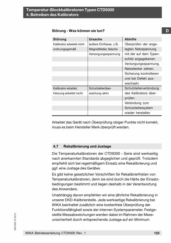
90
37
92
6 0
7/2
01
5
D
Temperatur-Blockkalibratoren Typen CTD93004. Betreiben des Kalibrators
Störung - Was können sie tun?
Störung
Kalibrator arbeitet nicht
ordnungsgemäß
Kalibrator arbeitet,
Heizung arbeitet nicht
Ursache
äußere Einflüsse, z.B.
Magnetfelder, falsche
Versorgungsspannung
Schutzleiterüber-
wachung aktiv
Abhilfe
Überprüfen der ange-
legten Netzspannung
mit der auf dem Typen-
schild angegebenen
Versorgungsspannung,
Netzstecker ziehen,
Sicherung kontrollieren
und bei Defekt aus-
wechseln
Schutzleiterverbindung
des Kalibrators über-
prüfen
Verbindung zum
Schutzleitersystem
wieder herstellen
Arbeitet das Gerät nach Überprüfung obiger Punkte nicht korrekt,muss es beim Hersteller Werk überprüft werden.
4.7 Rekalibrierung und Justage
Die Temperaturkalibratoren der CTD9300 - Serie sind werkseitig nach anerkannten Standards abgeglichen und geprüft. Trotzdem empfiehlt sich bei regelmäßigem Einsatz eine Rekalibrierung und ggf. eine Justage des Gerätes.
Es gibt keine gesetzlichen Vorschriften für Rekalibrierfristen vonTemperaturkalibratoren, denn sie sind durch die Härte der Einsatz-bedingungen bestimmt und liegen deshalb in der Verantwortungdes Anwenders.
Unabhängig davon empfehlen wir eine jährliche Rekalibrierung inunserer DKD-Kalibrierstelle. Jede werkseitige Rekalibrierung beiWIKA beinhaltet zusätzlich eine kostenfreie Überprüfung derFunktionsfähigkeit sowie der internen Systemparameter. Festge-stellte Messabweichungen werden dabei im Rahmen der Mess-unsicherheit durch entsprechende Justage auf ein Minimum
123WIKA Betriebsanleitung CTD9300 Rev. 1
90
37
92
6 0
7/2
01
5
Temperatur-Blockkalibratoren Typen CTD93004. Betreiben des Kalibrators
D
124 WIKA Betriebsanleitung CTD9300 Rev. 1
reduziert. Firmware-Updates können ebenfalls durchgeführtwerden.
Das DKD-Kalibrierzertifikat gibt Ihnen zudem die Sicherheit, dassIhre Kalibrierergebnisse auf nationale Normale zurückgeführt sindund die Messabweichungen angegebene Fehlergrenzen nichtüberscheiten.
Kalibrieren ist Vertrauenssache. Überlassen Sie deshalb Ihrewertvollen Geräte nur kompetenten DKD-Kalibrierstellen, die nachder Norm DIN EN ISO/IEC 17025 akkreditiert ist.
Verpacken Sie Geräte, die Sie zur Rekalibrierung versenden, sehrsorgfältig und verwenden Sie dabei nach Möglichkeit die Original-verpackung.
Im Hinblick auf eine möglichst schnelle Durchführung der Kalibrie-rung empfehlen wir unseren Kunden vorab mit unserer Kalibrier-stelle telefonisch einen Termin zu vereinbaren.
Rufen Sie unser Kalibrierlabor an oder schicken Sie eine E-mail.
4.8 Hinweise des DKD
Auszug aus den Hinweisen des DKD-Fachausschusses”Temperatur und Feuchte” zum Einsatz von Temperatur-Blockkalibratoren
Durch den Kalibrierschein eines DKD-Kalibrierlabors wird bestätigt,dass der Temperatur-Blockkalibrator die hohen Anforderungen andie Kalibrierbarkeit eines solchen Gerätes erfüllt, wie sie in derRichtlinie DKD-R 5-4 festgelegt sind. Dennoch sind beim Einsatzdes Kalibrators die folgenden Punkte zu beachten:
WIKA Alexander Wiegand SE & Co. KG Alexander-Wiegand-Straße 30D-63911 KlingenbergTel.: (+49) 93 72/132-5049Fax: (+49) 93 72/[email protected]
Die Anschrift unseres Labors lautet:
90
37
92
6 0
7/2
01
5
D
Temperatur-Blockkalibratoren Typen CTD93004. Betreiben des Kalibrators
125WIKA Betriebsanleitung CTD9300 Rev. 1
Die Kalibrierung von Temperatur-Blockkalibratoren bezieht sichvorwiegend auf die Temperatur des Festkörperblocks. Die Tempe-ratur des im Block zu kalibrierenden Thermometers kann von dieserTemperatur abweichen. Wenn ein Thermometer des gleichen Typsunter gleichen Messbedingungen wie bei der Kalibrierung verwen-det wird, kann davon ausgegangen werden, dass die Messab-weichungen bei der Kalibrierung von idealen Thermometern nichtgrößer sind als die im Kalibrierschein angegebenen Messunsicher-heiten. Falls im Kalibrierschein nichts anderes angegeben ist, musssichergestellt sein, dass
das Messelement sich in der homogenen Temperaturzonebefindet..
der Innendurchmesser der im Kalibrator benutzten Bohrung(evtl. der Hülse) im Temperaturbereich -80 °C bis 660 °Cmaximal 0,5 mm und im Temperaturbereich 660 °C bis 1300 °Cmaximal 1,0 mm größer ist als der Außendurchmesser des zukalibrierenden Thermometers.
die Eintauchtiefe des zu kalibrierenden Thermometers minde-stens das 15-fache des Außendurchmessers des zu kalibrieren-den Thermometers beträgt.
das zu kalibrierende Thermometer einen Außendurchmesserd <_ 6 mm hat.
Bei der Kalibrierung von Thermometern mit Außendurchmesserd > 6 mm ist eine zusätzliche Messabweichung durch Wärmeab-leitung zu berücksichtigen.
Falls solche Messungen durchgeführt werden sollen, so kann diezusätzliche Wärmeableitung für den bei Ihnen untersuchtenThermometertyp von Ihrem DKD-Kalibrierlaboratorium bestimmtwerden.
Ein guter Test auf mögliche Temperaturabweichungen durchWärmeableitung besteht darin, zu kontrollieren, ob sich die Anzeigedes zu kalibrierenden Thermometers ändert, wenn es um 20 mmangehoben wird. Beiträge zur Messunsicherheit, die durch das vonIhnen zu kalibrierende Thermometer bedingt sind (z. B. Inhomoge-nitäten von Thermoelementen), sind ebenfalls nicht in der Messun-sicherheit des Kalibrators enthalten.
90
37
92
6 0
7/2
01
5
Temperatur-Blockkalibratoren Typen CTD93004. Betreiben des Kalibrators
D
126 WIKA Betriebsanleitung CTD9300 Rev. 1
Falls der Kalibrator in Beladungszuständen eingesetzt wird, dienicht dem Beladungszustand bei der Kalibrierung entsprechen, sokann der Einfluss der Beladung durch Herausnahme oder Hinzufü-gen Thermometern vor Ort bestimmt werden.
Maßgeblich für die Kalibrierung sind die Angaben im Kalibrier-schein, nicht die Herstellerangaben. Sprechen Sie bitte vor derKalibrierung die Einsatz- und Kalibrierbedingungen mit unseremDKD-Kalibrierlaboratorium ab.
Wenn im Kalibrierschein nichts anderes angegeben ist, musssichergestellt sein, dass:
der Kalibrator in vertikaler Stellung betrieben wird.
keine zusätzlichen thermischen Isolierungen benutzt werden.
die Umgebungstemperatur (23 +_ 5) °C beträgt.
Zur Kontrolle der Kalibrierung von Temperatur-Blockkalibratorenwird empfohlen, regelmäßige Messungen mit einem kalibriertenThermometer vorzunehmen. Ohne Kontrollmessungen mit einemkalibrierten Thermometer wird eine jährliche Rekalibrierung desTemperatur-Blockkalibrators dringend empfohlen.
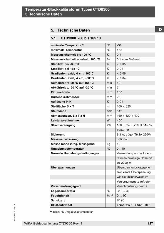
90
37
92
6 0
7/2
01
5
D
Temperatur-Blockkalibratoren Typen CTD93005. Technische Daten
127WIKA Betriebsanleitung CTD9300 Rev. 1
5. Technische Daten
5.1 CTD9300 -30 bis 165 °C
minimale Temperatur 1)
maximale Temperatur
Messunsicherheit bis 100 °C
Messunsicherheit oberhalb 100 °C
Stabilität bis -30 °C
Stabilität bei 165 °C
Gradienten axial, 4 cm, 165°C
Gradienten axial, 4 cm, -30 °C
Aufheizzeit v. 20 °C auf 165 °C
Abkühlzeit v. 20 °C auf -20 °C
Eintauchtiefe
Hülsendurchmesser
Auflösung in K
Stellfläche B x T
Stellfläche
Abmessungen, B x T x H
Leistungsaufnahme
Stromversorgung
Sicherung
Messwerterfassung
Masse (ohne integ. Messgerät)
Umgebungstemperatur
Normale Umgebungsbedingungen
Überspannungen
Verschmutzungsgrad
Lagertemperatur
Feuchtigkeit
Schutzart
CE-Konfirmität
°C
°C
K
%
K
K
K
K
min
min
mm
mm
K
mm
cm²
mm
W
VAC
kg
°C
°C
% rF
-30
165
0,1
0,1 vom Meßwert
< 0,05
0,01
< 0,06
< 0,04
12
7
160
28
0,01
160 x 320
512
160 x 320 x 420
400
100 ... 240 +10 %/-15 %
50/60 Hz
6,3 A, träge (T6,3A 250V)
optional
10
0...40
Verwendung nur in Innen-
räumen zulässige Höhe bis
zu 2000 m
Überspannungskategorie II
Transiente Überspannung,
wie sie üblicherweise im
Versorgungsnetz auftreten
Verschmutzungsgrad 2
-20 ... 40
0 ... 90
IP 20
EN61326-1, EN61010-1
1 )1 )1 )1 )1 ) bei 23 °C Umgebungstemperatur
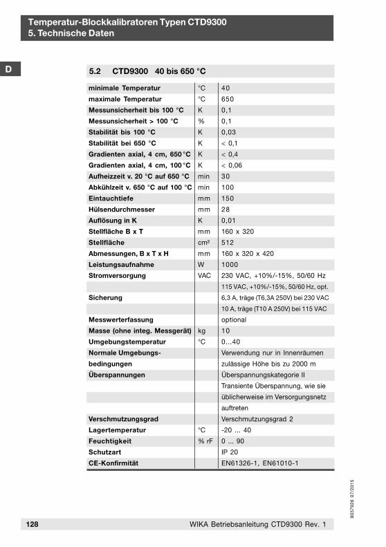
90
37
92
6 0
7/2
01
5
Temperatur-Blockkalibratoren Typen CTD93005. Technische Daten
D
128 WIKA Betriebsanleitung CTD9300 Rev. 1
5.2 CTD9300 40 bis 650 °C
minimale Temperatur
maximale Temperatur
Messunsicherheit bis 100 °C
Messunsicherheit > 100 °C
Stabilität bis 100 °C
Stabilität bei 650 °C
Gradienten axial, 4 cm, 650 °C
Gradienten axial, 4 cm, 100 °C
Aufheizzeit v. 20 °C auf 650 °C
Abkühlzeit v. 650 °C auf 100 °C
Eintauchtiefe
Hülsendurchmesser
Auflösung in K
Stellfläche B x T
Stellfläche
Abmessungen, B x T x H
Leistungsaufnahme
Stromversorgung
Sicherung
Messwerterfassung
Masse (ohne integ. Messgerät)
Umgebungstemperatur
Normale Umgebungs-
bedingungen
Überspannungen
Verschmutzungsgrad
Lagertemperatur
Feuchtigkeit
Schutzart
CE-Konfirmität
°C
°C
K
%
K
K
K
K
min
min
mm
mm
K
mm
cm²
mm
W
VAC
kg
°C
°C
% rF
40
650
0,1
0,1
0,03
< 0,1
< 0,4
< 0,06
30
100
150
28
0,01
160 x 320
512
160 x 320 x 420
1000
230 VAC, +10%/-15%, 50/60 Hz
115 VAC, +10%/-15%, 50/60 Hz, opt.
6,3 A, träge (T6,3A 250V) bei 230 VAC
10 A, träge (T10 A 250V) bei 115 VAC
optional
10
0...40
Verwendung nur in Innenräumen
zulässige Höhe bis zu 2000 m
Überspannungskategorie II
Transiente Überspannung, wie sie
üblicherweise im Versorgungsnetz
auftreten
Verschmutzungsgrad 2
-20 ... 40
0 ... 90
IP 20
EN61326-1, EN61010-1
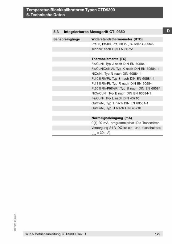
90
37
92
6 0
7/2
01
5
5.3 Integrierbares Messgerät CTI 9350 D
Temperatur-Blockkalibratoren Typen CTD93005. Technische Daten
129WIKA Betriebsanleitung CTD9300 Rev. 1
Widerstandsthermometer (RTD)
Pt100, Pt500, Pt1000 2- , 3- oder 4-Leiter-
Technik nach DIN EN 60751
Thermoelemente (TC)
Fe/CuNi, Typ J nach DIN EN 60584-1
Fe/CuNiCr/NiAl, Typ K nach DIN EN 60584-1
NiCr/Ni, Typ N nach DIN 60584-1
Pt10%Rh/Pt, Typ S nach DIN EN 60584-1
Pt13%Rh-Pt, Typ R nach DIN EN 60584
Pt30%Rh-Pt6%Rh,Typ B nach DIN EN 60584
NiCr/CuNi, Typ E nach DIN EN 60584-1
Fe/CuNi, Typ L nach DIN 43710
Cu/CuNi, Typ T nach DIN EN 60584-1
Cu/CuNi, Typ U Nach DIN 43710
Normsignaleingang (mA)0(4)-20 mA, programmierbar (Die Transmitter-
Versorgung 24 V DC ist ein- und ausschaltbar,
Imax
= 30 mA)
Sensoreingänge
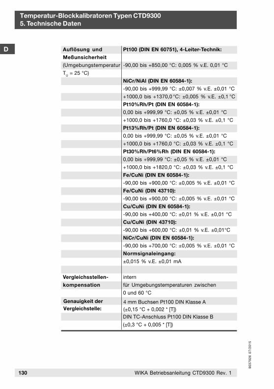
90
37
92
6 0
7/2
01
5
Temperatur-Blockkalibratoren Typen CTD93005. Technische Daten
D
130 WIKA Betriebsanleitung CTD9300 Rev. 1
Vergleichsstellen-
kompensation
Pt100 (DIN EN 60751), 4-Leiter-Technik:
-90,00 bis +850,00 °C: 0,005 % v.E. 0,01 °C
NiCr/NiAl (DIN EN 60584-1):
-90,00 bis +999,99 °C: ±0,007 % v.E. ±0,01 °C
+1000,0 bis +1370,0 °C: ±0,005 % v.E. ±0,1 °C
Pt10%Rh/Pt (DIN EN 60584-1):
0,00 bis +999,99 °C: ±0,05 % v.E. ±0,01 °C
+1000,0 bis +1760,0 °C: ±0,03 % v.E. ±0,1 °C
Pt13%Rh/Pt (DIN EN 60584-1):
0,00 bis +999,99 °C: ±0,05 % v.E. ±0,01 °C
+1000,0 bis +1760,0 °C: ±0,03 % v.E. ±0,1 °C
Pt30%Rh/Pt6%Rh (DIN EN 60584-1):
0,00 bis +999,99 °C: ±0,05 % v.E. ±0,01 °C
+1000,0 bis +1820,0 °C: ±0,03 % v.E. ±0,1 °C
Fe/CuNi (DIN EN 60584-1):
-90,00 bis +900,00 °C: ±0,005 % v.E. ±0,01 °C
Fe/CuNi (DIN 43710):
-90,00 bis +900,00 °C: ±0,005 % v.E. ±0,01 °C
Cu/CuNi (DIN EN 60584-1):
-90,00 bis +400,00 °C: ±0,01 % v.E. ±0,01 °C
Cu/CuNi (DIN 43710):
-90,00 bis +600,00 °C: ±0,01 % v.E. ±0,01°C
NiCr/CuNi (DIN EN 60584-1):
-90,00 bis +700,00 °C: ±0,005 % v.E. ±0,01 °C
Normsignaleingang:
±0,015 % v.E. ±0,01 mA
intern
für Umgebungstemperaturen zwischen
0 und 60 °C
Auflösung und
Meßunsicherheit
(Umgebungstemperatur
TU = 25 °C)
Genauigkeit der Vergleichstelle:
4 mm Buchsen Pt100 DIN Klasse A(±0,15 °C + 0,002 * [T])DIN TC-Anschluss Pt100 DIN Klasse B
(±0,3 °C + 0,005 * [T])
90
37
92
6 0
7/2
01
5
D
Temperatur-Blockkalibratoren Typen CTD93006. Anhang
131WIKA Betriebsanleitung CTD9300 Rev. 1
Die Kalibriergeräte CTD9300 sind tragbare Einheiten, die sowohl als flexibel einsetzbares Gerät für Servicezwecke vor Ort - als auch für Betriebs- und Laboraufgaben verwendet werden können.
Transportieren Sie den Kalibrator nach Möglichkeit in seinemOriginal-Transportkoffer. Der robuste Koffer ist auf die Abmessun-gen und das Gewicht des Kalibrators abgestimmt und schützt ihnvor Umwelteinflüssen wie Stoß, Schock, Staub, Spritzwasser undvor äußerer Beschädigung.
Warten Sie stets bis das Gerät die Blocktemperatur von 30 °Cunterschritten hat, bevor Sie den Kalibrator verpacken.
6.2 Lagerung
Die CTD9300 müssen staubgeschützt und trocken gelagert werden. Die Umgebungstemperatur für die Lagerung muss zwischen -10 °C und +80 °C liegen.
6. Anhang
6.1 Transport
6.3 Entsorgung
Die Firma WIKA sorgt für eine sachgerechte Entsorgung gebrauch-ter Temperatur-Blockkalibratoren. Schicken Sie die Kalibratoren der CTD9300-Serie dazu einfach frachtfrei an die Firma WIKA zurück.
6.4 Pflege und Wartung
Halten Sie die CTD9300 stets sauber und lassen Sie ihn niemals in staubigen oder feuchten Räumen stehen.
Reinigen Sie die Kalibratoren ggf. nach dem Gebrauch. Ziehen Sievor dem Reinigen den Netzstecker und achten Sie darauf, dass dieBlocktemperatur weniger als 30 °C beträgt.
Verwenden Sie keine scharfen Reinigungsmittel sondern lediglichein leicht angefeuchtetes, fusselfreies Tuch.
Vermeiden Sie Messfehler, indem Sie die Bohrungen des Blocksstets sauber halten und zum Messen keine Füllmedien benutzen.
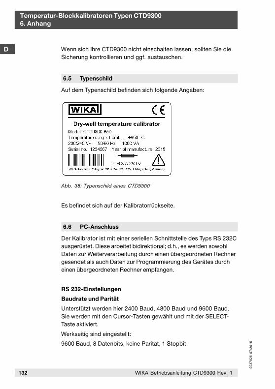
90
37
92
6 0
7/2
01
5
Temperatur-Blockkalibratoren Typen CTD93006. Anhang
D
132 WIKA Betriebsanleitung CTD9300 Rev. 1
Wenn sich Ihre CTD9300 nicht einschalten lassen, sollten Sie die Sicherung kontrollieren und ggf. austauschen.
6.5 Typenschild
Auf dem Typenschild befinden sich folgende Angaben:
Es befindet sich auf der Kalibratorrückseite.
Abb. 38: Typenschild eines CTD9300
6.6 PC-Anschluss
Der Kalibrator ist mit einer seriellen Schnittstelle des Typs RS 232Causgerüstet. Diese arbeitet bidirektional; d.h., es werden sowohlDaten zur Weiterverarbeitung durch einen übergeordneten Rechnergesendet als auch Daten zur Programmierung des Gerätes durcheinen übergeordneten Rechner empfangen.
RS 232-Einstellungen
Baudrate und Parität
Unterstützt werden hier 2400 Baud, 4800 Baud und 9600 Baud.Sie werden mit den Cursor-Tasten gewählt und mit der SELECT-Taste aktiviert.
Werkseitig sind eingestellt:
9600 Baud, 8 Datenbits, keine Parität, 1 Stopbit
90
37
92
6 0
7/2
01
5
D
Temperatur-Blockkalibratoren Typen CTD93006. Anhang
133WIKA Betriebsanleitung CTD9300 Rev. 1
Protokoll
Hier stehen 3 Protokollformate zur Auswahl:
Standard: Standard-Protokoll, das immer dann eingestelltsein muss, wenn die Kalibratoren zusammen mitunserem Kalibrierprogramm betrieben werden.
Test: werksinternes Testprotokoll
Display: werksinternes Testprotokoll
Die Protokollarten werden mit den Cursor-Tasten ausgewählt undmit der SELECT-Taste aktiviert.
Befehlssatz
Der Befehlssatz ist nicht Bestandteil dieser Anleitung. Er kann ggf.interessierten Anwendern zur Verfügung gestellt werden. WendenSie sich hierzu bitte an den Hersteller.
Pinbelegung des RS 232-Kabels
Die Verbindung von PC und Kalibrator erfolgt über ein handels-übliches 1:1-RS 232-Kabel

WIKA Alexander Wiegand SE & Co. KG Alexander-Wiegand-Straße 3063911 Klingenberg • GermanyPhone (+49) 93 72/132-0Fax (+49) 93 72/132-406E-Mail [email protected]
Technical alteration rights reserved.Technische Änderungen vorbehalten.