Embed Size (px)
Citation preview

Wiedenmann
Operating Instructions
Deep Aerator Terra Spike
XP 6 / XP 8 / XP 10
415.000 - US
Effective May 2002
Wiedenmann GmbH - D 89192 Rammingen
Tel. No.: 0049 / 7345 / 953-02 Fax No.: 0049 / 7345 / 953233
Wiedenmann North America 2700 Gregory Street, Savannah GA 31410
912-790-3004 912-790-3005 (fax)

Alle Informationen, Abbildungen und technische Angaben in dieser Publikation entsprechen dem neuesten Stand zum Zeitpunkt der Veröffentlichung. Konstruktionsänderungen jederzeit und ohne Bekanntgabe vorbehalten.
2

Alle Informationen, Abbildungen und technische Angaben in dieser Publikation entsprechen dem neuesten Stand zum Zeitpunkt der Veröffentlichung. Konstruktionsänderungen jederzeit und ohne Bekanntgabe vorbehalten.
3
Warranty As stated on the warranty certificate you receive when you purchase
the machine, a one year warranty is offered which covers all
malfunctioning parts where the fault is demonstrated as being due to a
structural or material defect. Claims under the warranty should be
made within three days of the fault's occurrence enclosing the receipt
and guarantee certificate. The warranty provides for the gratuitous
replacement of defective parts. Damage caused by improper treatment,
non-observance of the operating instructions, insufficient care or
external influences is not covered by the warranty. Careful observance
of the instructions contained in the operating instructions is,
therefore, a precondition for perfect machine operation.
Improper operation leads to malfunctions which are not covered in the
warranty.
Wiedenmann GmbH * Am Bahnhof * D 89192 Rammingen * Fax: 0049 / 7345 / 953233
EC-Declaration of Conformity We Wiedenmann GmbH Am Bahnhof 89192 Rammingen declare under our sole responsibility, that the product
Deer Aerator Terra Spike XP6 / XP8 / XP10
to which this declaration relates corresponds to the relevant basic safety and health requirements of the Directive 89/392 (ECC).
Rammingen, the 18. June 2001 Peter Rischar Technical Service (Place and date of issue) (Name, function and signature
of authorised person)
Deleted: ,sowie den Anforderungen der einschlägigen

Alle Informationen, Abbildungen und technische Angaben in dieser Publikation entsprechen dem neuesten Stand zum Zeitpunkt der Veröffentlichung. Konstruktionsänderungen jederzeit und ohne Bekanntgabe vorbehalten.
4
Introduction READ THIS MANUAL carefully to learn how to operate and service your machine correctly. Failure to do so could result in personal injury or equipment damage. This manual and safety signs on your machine may also be available in other languages (see your dealer to order).
THIS MANUAL SHOULD BE CONSIDERED a permanent part of your machine and should remain with the machine when you sell it.
MEASUREMENTS in this manual are given in both metric and customary U.S. unit equivalents. Use only correct repacement parts and fasteners. Metric and inch fasteners may require a specific metric or inch wrench.
RIGHT - HAND AND LEFT - HAND sides are determined by facing the direction the implement will travel when going forward.
WRITE PRODUCT IDENTIFICATION NUMBERS (P.I.N.) in the Specification or Identification Numbers section. Accurately record all the numbers to help in tracing the machine should it be stolen. Your dealer also needs these numbers when you order parts. File the identification numbers in a secure place away from the machine.
BEFORE DELIVERING THIS MACHINE, your dealer performed a pre-delivery inspection to ensure best performance.
THIS MACHINE IS DESIGNED SOLELY for use in customary agricultural and forestry operations, for lawn and park care, i.e. collecting grass, leaves and paper (“INTENDED USE“).
Use in any other way is considered as contrary to the intended use. The manufacturer accepts no liability for damage or injury resulting from this misuse, and these risks must be borne solely by the user. Compliance with and strict adherence to the conditions of operation, service and repair as specified by the manufacturer also constitute essential elements for the intended use.
THIS MACHINE SHOULD BE OPERATED, serviced and repaired only by persons familiar with all its particular characteristics and acquainted with the relevant safety rules (accident prevention). The accident prevention regulation, all other generally recognized regulations on safety and occupational medicine and the road traffic regulations must be observed at all times. Any arbitrary modifications carried out on this material collection system will relieve the manufacturer of all liability for any resulting damage or injury.
THE TRACTORS must be conform with the EN836

Alle Informationen, Abbildungen und technische Angaben in dieser Publikation entsprechen dem neuesten Stand zum Zeitpunkt der Veröffentlichung. Konstruktionsänderungen jederzeit und ohne Bekanntgabe vorbehalten.
5
C O N T E N T S Page * * * * * * * * * * * * * * * * * * * * * * * * * * * * * * * * * * * * * * * * * * * * * * * * * * *
1.0. Safety..................................................5-11
1.1. Safety Decals....................................9&10
1.2. Safety Equipment................................. 11
2.0. Construction method of Operation....................... 12
2.1. Construction..................................... 12
2.2. Method of Operation.............................. 12
2.3. Product Observating.............................. 12
3.0. Transport.............................................. 13&14
3.1. General.......................................... 13
3.2. Transporting Terra Spike......................... 14
4.0. Connecting to the Tractor.............................. 15&16
4.1. General.......................................... 15
4.2. Connecting to the Tractor........................ 16
5.0. Detaching from Tractor................................. 17
5.1. General.......................................... 17
5.2. Resting Terra Spike.............................. 17
6.0. Operating............................................... 18-27
6.1. General.......................................... 18
6.2. Indicating and Adjustment Elements............... 19
6.3. Mounting the Tools............................... 20-22
6.4. Setting the Working Depth........................ 23-25
6.5. Traval adjustments............................... 25
6.6. Setting the Number of Holes...................... 26&27
7.0. Operation.............................................. 28&29
7.1. General.......................................... 28
7.2. Correct Sequence for engaging....................29
7.3. Malfunctions and Remedy.......................... 29
8.0. Maintenance............................................ 30-35
8.1. General.......................................... 30
8.2. Maintenance and Inspection List.................. 30
8.3. Lubrication...................................... 31
8.4. Cleaning TERRA SPIKE............................. 32
8.5. Changing the oil of the gear unit................ 33
8.6. Replacing the buffer............................. 33
8.7. Setting cleaner.................................. 34
8.8. Hydraulic system................................. 34
8.9. Dismounting/Disposal............................. 35
8.10. Modification.................................... 35
9.0. Additional Equipment................................... 36&37
10.0. Specification.......................................... 38-46

Alle Informationen, Abbildungen und technische Angaben in dieser Publikation entsprechen dem neuesten Stand zum Zeitpunkt der Veröffentlichung. Konstruktionsänderungen jederzeit und ohne Bekanntgabe vorbehalten.
6
1.0. Safety Recognize safety information This is the safety-alert symbol. When you see this symbol on your machine or in this manual, be alert to the potential for personal injury.
Follow recommended precautions and safe operating practices.
Follow safety instuctions Carefully read all safety messages in this manual and on your machine safety signs. Keep safety signs in good condition. Replace missing or damaged safety signs. Be sure new equipment components and repair parts include the current safety signs. Replacement safety signs are available from your dealer.
Learn how to operate the machine and to use controls properly. Do not let anyone operate without instruction.
Keep your machine in proper working condition. Unauthorized modifications to the machine may impair the fuction and/or safety and affect machine life.
If you do not understand any part of this manual and need assistance, contact your dealer.
Observe road traffic regulations Always observe local road traffic regulations when using public roads.

Alle Informationen, Abbildungen und technische Angaben in dieser Publikation entsprechen dem neuesten Stand zum Zeitpunkt der Veröffentlichung. Konstruktionsänderungen jederzeit und ohne Bekanntgabe vorbehalten.
7
1.0. Safety Wear protective clothing Wear close fitting clothing and safety equipment appropriate to the job.
Prolonged exposure to loud noise can cause impairment or loss of hearing.
Wear a suitable hearing protective device such as earplugs to protect against objectionable or uncomfortably loud noises.
Operating equipment safety requires the full attention of the operator. Do not wear radio or music headphones while operating machine.
Stay clear of rotating drivelines Entanglement in rotating driveline can cause serious injury or death.
Keep tractor master shield and driveline shields in place at all times. Make sure rotating shields turn freely.
Wear close fitting clothing. Stop the engine and be sure PTO driveline is stopped before making adjustments, connections, or cleaning out PTO driven equipment.
Guard and shields Keep guards and shields in place all the times. Ensure that they are in good condition and installed correctly.
Always disengage the driveline, turn off engine and remove key before removing any guards or shields.
Keep hands, feet and clothing away from moving parts.

Alle Informationen, Abbildungen und technische Angaben in dieser Publikation entsprechen dem neuesten Stand zum Zeitpunkt der Veröffentlichung. Konstruktionsänderungen jederzeit und ohne Bekanntgabe vorbehalten.
8
1.0. Safety Use safety lights and devices Prevent collisions between other road users, slow moving tractors with attachments or towed equipment, and self-propelled machines on public roads. Frequently check for traffic from the rear, especially in turns, and use hand signals or turn signal lights. Use headlights, flashing warning lights, and turn signals day and night. Follow local regulations for equipment lighting and marking. Keep lighting and marking visible and in good working order. Replace or repair lighting and marking that has been damaged or lost. An implement safety lighting kit is available from your dealer.
Avoid heating near pressurized fluid lines Flammable spray can be generated by heating near pressurized fluid lines, resulting in severe burns to yourself and bystanders. Do not heat by welding, soldering, using a torch near pressurized fluid lines or other flammable materials. Pressurized lines can be accidentally cut when heat goes beyond the immediate flame area.

Alle Informationen, Abbildungen und technische Angaben in dieser Publikation entsprechen dem neuesten Stand zum Zeitpunkt der Veröffentlichung. Konstruktionsänderungen jederzeit und ohne Bekanntgabe vorbehalten.
9
1.0. Safety Remove paint before welding or heating Avoid potentially toxic fumes and dust.
Hazardous fumes can be generated when paint is heated by welding, soldering, or using a torch.
Do all work outside or in a well ventilated area. Dispose of paint and solvent properly.
Remove paint before welding or heating:
• If you sand paint, avoid breathing the dust. Wear an approved respirator.
• If you use solvent or paint stipper, clean with soap and water before welding. Remove solvent or paint stripper containers and other flammable material from area. Allow fumes to disperse at least 15 minutes before welding or heating.
Avoid high - pressure fluids Escaping fluid under pressure can penetrate the skin causing serious injury.
Avoid the hazard by relieving pressure before disconnecting hydraulic or other lines. Tighten all connections before applying pressure.
Search for leaks with a piece of cardboard. Protect hands and body from high pressure fluids.
If an accident occurs, see a doctor immediately. Any fluid injected into the skin must be surgically removed within a few hours or gangrene may result. Doctors unfamiliar with this type of injury should reference a knowledgeable medical source.

Alle Informationen, Abbildungen und technische Angaben in dieser Publikation entsprechen dem neuesten Stand zum Zeitpunkt der Veröffentlichung. Konstruktionsänderungen jederzeit und ohne Bekanntgabe vorbehalten.
10
1.0. Safety 1.1. Safety Decals
Pictorial safety signs At several important places on this machine safety signs are affixed in order to signify potential danger. The hazard is identified by a exclamation point in a warning triangle. An adjacent pictorial provides information on how to avoid personal injury. These safety signs, their placement on the nachine and a brief explanatory text are shown below. Operator’s manual This operator’s manual contains all important information necessary for safe machine operation. Carefully observe all safety rules to avoid accidents. Protectors Never reach into areas of crushing hazard as long as any parts may move.
415.01
415.02

Alle Informationen, Abbildungen und technische Angaben in dieser Publikation entsprechen dem neuesten Stand zum Zeitpunkt der Veröffentlichung. Konstruktionsänderungen jederzeit und ohne Bekanntgabe vorbehalten.
11
1.0. Safety 1.1. Safety Decals
Parking position Before parking fix rear roller with ring pins and secure it. Tools Never touch moving parts of the machine. Wait until they have come to a complete standstill. Tools Be careful to avoid cutting of foot. Service Before performing service or repair work, turn off engine and remove key.
415.03
415.04
415.05
415.06
Alle Informationen, Abbildungen und technische Angaben in dieser Publikation entsprechen dem neuesten Stand zum Zeitpunkt der Veröffentlichung. Konstruktionsänderungen jederzeit und ohne Bekanntgabe vorbehalten.
12
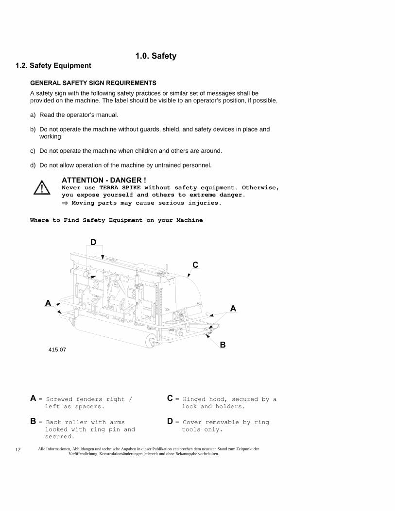
1.0. Safety 1.2. Safety Equipment
GENERAL SAFETY SIGN REQUIREMENTS A safety sign with the following safety practices or similar set of messages shall be provided on the machine. The label should be visible to an operator’s position, if possible. a) Read the operator’s manual.
b) Do not operate the machine without guards, shield, and safety devices in place and
working.
c) Do not operate the machine when children and others are around.
d) Do not allow operation of the machine by untrained personnel.
ATTENTION - DANGER ! Never use TERRA SPIKE without safety equipment. Otherwise, you expose yourself and others to extreme danger. ⇒ Moving parts may cause serious injuries.
Where to Find Safety Equipment on your Machine
A = Screwed fenders right / left as spacers.
B = Back roller with arms locked with ring pin and secured.
C = Hinged hood, secured by a lock and holders.
D = Cover removable by ring tools only.
A
D
B
A
C
415.07

2.0. Construction and Method of Operation 2.1. Construction
TERRA SPIKE consists of the following parts:
• Welded machine body
• Drive
• Adjustable tools Three gear speeds can be selected on TERRA SPIKE.
2.2. Method of Operation TERRA SPIKE is hauled by the tractor and driven by means of a PTO shaft.
A gear unit inside TERRA SPIKE provides for movement of the tines.
The moving tines are forced into the soil.
The angle of entry is adjustable.
With an entry angle of 90° at low speed the punched holes are almost vertical.
With a smaller entry angle, the soil displacement or fracturing is
greater due to the forward movement. This breaks up the soil. (Effective down to 70°)
2.3. Product observation We are bound law to observe our products starting with the delivery.
This serves your safety.
Please immediately inform us about:
• Defects of the dafety devices.
• Repeated malfunctions.
• Altered setting.
• Problems in handling the TERRA SPIKE.

All information, illustrations and specifications in this manueal arw based on the latest information available at the time of publication. The right is reserved to make changes at any time without notice.
14
3.0. Transport 3.1. General
CAUTION DANGER !
° TERRA SPIKE is delivered fastened to a shipment frame.
° Only use a forklift with sufficient load-carrying capacity.
° Keep well clear of lifted loads. There is danger to your life if the load crashes down.
Improper transport and mounting of TERRA SPIKE may cause:
• Injury to persons
• Demage to property. Pay special attention to the driving direction when lifting TERRA SPIKE with the shipment frame.
We will not accept any liability for damage resulting from improper handling.

All information, illustrations and specifications in this manueal arw based on the latest information available at the time of publication. The right is reserved to make changes at any time without notice.
15
3.0. Transport 3.2. Transporting TERRA SPIKE
CAUTION DANGER ! Watch out when cutting through the taut bands. There is a risk of being injured by the suddenly opening bands. Transport Using a Forklift If TERRA SPIKE is still fastened to the shipment frame:
• Insert the fork under the shipment frame
• Unload TERRA SPIKE from the carrier vehicle when balanced.
• Cut through the taut bands.
• Connect TERRA SPIKE to the tractor and lift it from the shipment frame. (See item 4.2.)
Transport Using a Crane • Fasten ropes or belts at ring
screw (A) only,
• Unload TERRA SPIKE when suspended reliably.
Note: Immediately inform in writing the transport company and Wiedenmann GmbH or the supplier about shipping damage or missing parts.

All information, illustrations and specifications in this manueal arw based on the latest information available at the time of publication. The right is reserved to make changes at any time without notice.
16
4.0. Connecting to the Tractor 4.1. General
Always pay attention to: • The load of the three point hitch.
Connect / disconnect TERRA SPIKE only with:
• The engine turned off
• Disengate PTO shaft
• With fixed and secured back roller (in parking/stand position)
Use TERRA SPIKE only with:
• the special PTO shaft assigned to TERRA SPIKE
• covered PTO shaft and protected power-take-off shaft.
Rest TERRA SPIKE on the front roller (A) and back roller (B) only.
All information, illustrations and specifications in this manueal arw based on the latest information available at the time of publication. The right is reserved to make changes at any time without notice.
17
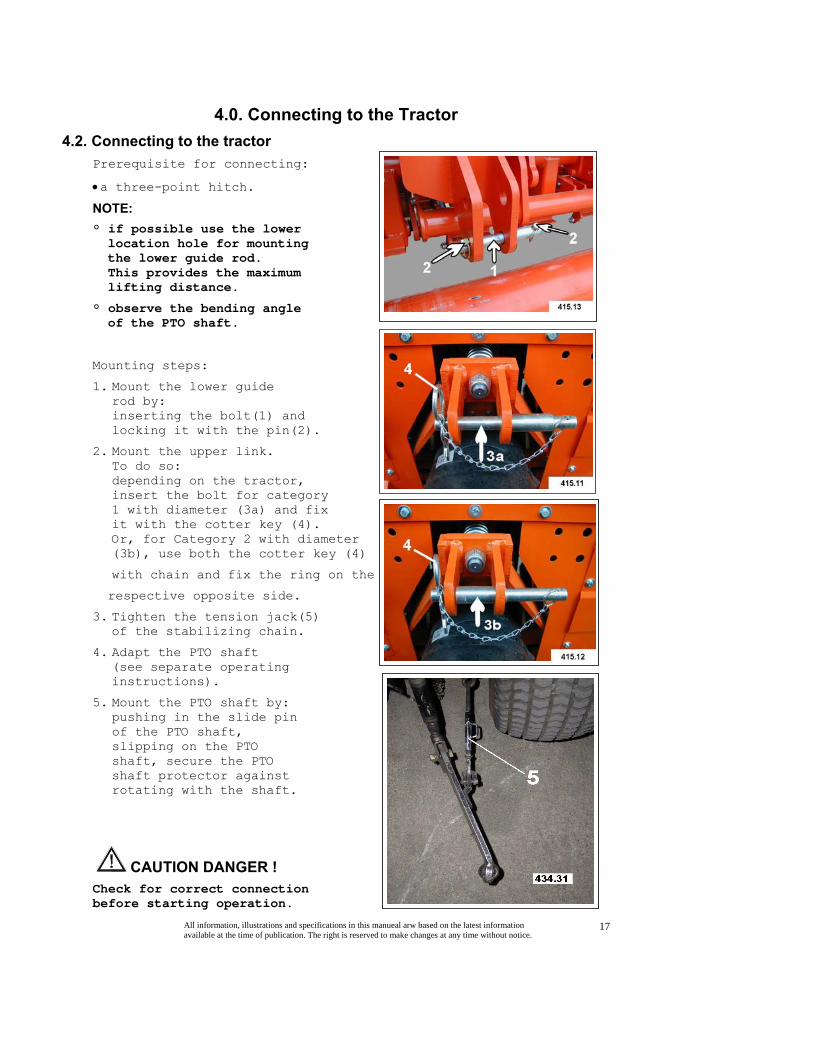
4.0. Connecting to the Tractor 4.2. Connecting to the tractor
Prerequisite for connecting:
• a three-point hitch.
NOTE: ° if possible use the lower location hole for mounting the lower guide rod. This provides the maximum lifting distance.
° observe the bending angle of the PTO shaft.
Mounting steps:
1. Mount the lower guide rod by: inserting the bolt(1) and locking it with the pin(2).
2. Mount the upper link. To do so: depending on the tractor, insert the bolt for category 1 with diameter (3a) and fix it with the cotter key (4). Or, for Category 2 with diameter (3b), use both the cotter key (4)
with chain and fix the ring on the
respective opposite side.
3. Tighten the tension jack(5) of the stabilizing chain.
4. Adapt the PTO shaft (see separate operating instructions).
5. Mount the PTO shaft by: pushing in the slide pin of the PTO shaft, slipping on the PTO shaft, secure the PTO shaft protector against rotating with the shaft.
CAUTION DANGER ! Check for correct connection before starting operation.
All information, illustrations and specifications in this manueal arw based on the latest information available at the time of publication. The right is reserved to make changes at any time without notice.
18
5.0. Disconnecting from the Tractor 5.1. General
Only rest TERRA SPIKE: • on a solid and even base, • on fully lowered front and
secured back roller. This provides for a safe stand of TERRA SPIKE and prevents the tines from being damaged.
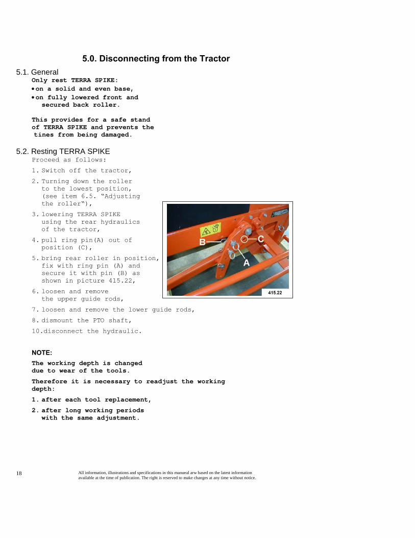
5.2. Resting TERRA SPIKE Proceed as follows:
1. Switch off the tractor, 2. Turning down the roller
to the lowest position, (see item 6.5. “Adjusting the roller“),
3. lowering TERRA SPIKE using the rear hydraulics of the tractor,
4. pull ring pin(A) out of position (C),
5. bring rear roller in position, fix with ring pin (A) and secure it with pin (B) as shown in picture 415.22,
6. loosen and remove the upper guide rods,
7. loosen and remove the lower guide rods, 8. dismount the PTO shaft, 10.disconnect the hydraulic.
NOTE: The working depth is changed due to wear of the tools.
Therefore it is necessary to readjust the working depth:
1. after each tool replacement, 2. after long working periods
with the same adjustment.

All information, illustrations and specifications in this manueal arw based on the latest information available at the time of publication. The right is reserved to make changes at any time without notice.
19
6.0. Before Using 6.1. General
ATTENTION ! It is important to become familiar with all devices and operating elements as well as their action before starting service to make sure that all protective devices have been properly mounted. It will be too late for this during operation! Make sure that noone is in the risk area of the appliance and the turning PTO shaft before turning on the power take-off shaft. Observing the operating instructions, also pay attention to general safety specifications and rules for prevention of accidents! Corresponding specifications must be observed on public roads! The weight on the axle in front must be enough to maintain steerability (if needed, put on ballast weights, see operator’s manual of tractor). Be careful working on slopes – risk of overturning! -

All information, illustrations and specifications in this manueal arw based on the latest information available at the time of publication. The right is reserved to make changes at any time without notice.
20
6.0. Before Using 6.2. Indicating and adjustment elements
Shift lever(A) for the 3 gear speeds of the machine (speed 3 is seen on the photo 415.14). NOTE: The shift lever (A) must snap into place with an audible sound. If necessary move the gear by applying pressure to a tine holder while standing up
Crank (B) for adjusting the working depth (by raising or lowering the roller).
Scale (C) for tool length; depth scale (D) to read the set operating depth; ruler (E) and pointer (F)
Crank (G) and spindle (H) for adjusting the entry angle.
On the machine types XP8 and XP10, crank (G) and spindle (H) are present on both sides; this means that the adjustment of the entry angle must be done on both sides.
Take care to adjust the same entry angle on both sides!

All information, illustrations and specifications in this manueal arw based on the latest information available at the time of publication. The right is reserved to make changes at any time without notice.
21
6.0. Before Using 6.3. Mounting the Tools
NOTE When mounting the tines:
1. Lift up TERRA SPIKE with tractor hydraulic.
2. Adjust front roller to lowest position.
3. Put down TERRA SPIKE on front roller.
4. Shift the tine holder you are working with upwards (by pressing an upper tine holder).
5. Lubricate the tine holder in the receiving area.
6. In installation position the pointed end of the tine (A) must be backward (in driving direction).
7. To protect the cone support of tine holders, screws and washer are installed. The cylindric supports which are not in use are protected by plastic caps.
8. Wrench (B) is for adjusting and removing the tines.
A
FahrtrichtungDirection of motionDirection de la marche

All information, illustrations and specifications in this manueal arw based on the latest information available at the time of publication. The right is reserved to make changes at any time without notice.
22
6.0. Before Using 6.3.1. Mounting the tines into the tine head: 1. Shift up the
tine holder(A).
2. Screw (D) and remove washer (E).
3. Adjust nut (B) with provided wrench so that
you can see one thread (C) of the tine.
4. Place tine (F) into the conical support and bolt it completely into nut (B).
5. The slanted edge of tine should be pointed toward
front of the machine so that when
looking at the machine from the
rear, the slanted edge cannot be
seen.
6. By removing the tines (F) adjust position edge.
7. Put wrench on nut (B). 8. Hold tine with one
hand firmly.
9. Fix tine by tightening the nut (B).
NOTE Check all tines for tight fit:
• Before using them
• If they just have been mounted, after three minutes of use.
FahrtrichtungDirection of motionDirection de la marche
AB
C
D
E
F
434.35
A

All information, illustrations and specifications in this manueal arw based on the latest information available at the time of publication. The right is reserved to make changes at any time without notice.
23
6.0. Using 6.3.2. Mounting tines into the cylindrical receiver:
1. Remove plastic cap (D) at tine holder (A).
2. Loosen nut (C). 3. Place 1/2“ tine (E)
or 5/16“ tine (F) with bushing (G) as shown in illustration.
4. Fix screw (B) in lowering of tines.
5. Fix counter nut (C) to fix screw (B).
6. Check the tines for tight fit.
NOTE Check all tines for tight fit:
• Before using them
• If they just have been mounted, after three minutes of use.
FahrtrichtungDirection of motionDirection de la marche
FahrtrichtungDirection of motionDirection de la marche
A
B
C
D
E
FG
434.38

All information, illustrations and specifications in this manueal arw based on the latest information available at the time of publication. The right is reserved to make changes at any time without notice.
24
6.0. Before Using 6.4. Adusting the TERRA SPIKE
NOTE Always make adjustments when the device has been attached and lifted out.
On delivery of the TERRA SPIKE the rake angle is set to zero position.
Each time the device is adjusted, the tool length “A“ needs to be measured. The measure “B“ represents the desired working depth.
Sequence when adjusting the TERRA SPIKE : 1)Adjust working depth: a) Release spring pin (A) b) shift locking piston (B) into direction of arrow c) Unscrew nut and bolt (E). Adjust the pointer on ruler (C) to the measured tool length and tighten it with bolt and nut (E). d) Rotate the crank until the pointer (D) has reached the desired working depth on the scale (F). e) Push the locking piston (B) back and insert the spring pin (A) in order to lock it again.
415.19
A
B

All information, illustrations and specifications in this manueal arw based on the latest information available at the time of publication. The right is reserved to make changes at any time without notice.
25
6.0. Before Using 6.4. Adjusting the TERRA SPIKE
2)Release the stop-motion device of the trailing cylinder, for this end plug the pin (A) into the hole(C).
3)Lower the TERRA SPIKE onto a cylinder feeler.
4)Put the TERRA SPIKE into a vertical position, for this end: • Unscrew the locknut (D) of the upper link • Use the upper link (E) to adjust the device ADJUSTMENT: the front edge (V) must be placed vertically • draw up the lock nut (D) of the above pull rod.
5)The hoeing effect of the tools in the ground is achieved by the crank (G) and the spindle (H).
We recommend using a position from 0 to 15.
← Position 0
↑ Position 5
→ Position 10
↓ Position 15
NOTE: On the models XP8 and XP10, the adjustment must be done on both sides. Take care to set the same adjustment!

All information, illustrations and specifications in this manueal arw based on the latest information available at the time of publication. The right is reserved to make changes at any time without notice.
26
6.0. Before Using 6.4. Adjusting the TERRA SPIKE
6)For working with hollow tines we recommend putting the trailing cylinder upright;
for this end: • Lift out the TERRA SPIKE • Lift off the trailing cylinder by hand • Release pin (A) and plug it into the bottommost hole of the adjusting strap (F).
6.5. Travel adjustments
By default, the link rods (A) are mounted in position P1 as shown in Fig. 415.27.
At a maximum travel of 350 mm (14in.), a maximum working depth of 350 mm (14in.) can be achieved.
The max. tine length is 350 mm (14in.).
If it is desired to achieve a maximum working depth of 400 mm (16 in.), the link rods can be mounted in position P2 as shown in Fig. 415.28. There are no additional parts required.
The max. tine length is 400 mm (16in.).
When work is done using the long travel setting, it is necessary to adjust the device one step lower than when using the short travel.
The lowest position of the tool carriers is always the same.

All information, illustrations and specifications in this manueal arw based on the latest information available at the time of publication. The right is reserved to make changes at any time without notice.
27
6.0. Before Using 6.6. Setting the number of holes
NOTE The number of holes (per tine and minute) depends on: • The speed of the tractor‘s
power take-off shaft,
• The chosen gear speed, (lever (A) in gear speed 3 see photo).
For 3/4“ or 1“ tines use gear I and II only!
If the hole distance is too small: • Increase the driving
speed, or
• Decrease the speed of the power take-off shaft.
If the hole distance too wide: • Low driving speed or
• raise PTO.
Speed of power take-off = number of holes per tine:
Gear speed
300 350 400 450 500 540
I 80 84 107 121 134 145
II 92 107 122 138 153 165
III 104 121 139 156 173 187
Speed of Power Take-off Shaft (rpm)

All information, illustrations and specifications in this manueal arw based on the latest information available at the time of publication. The right is reserved to make changes at any time without notice.
28
6.0. Before Using 6.6.1. Setting the hole distance
The hole distances depend on: • the speed of the power take-off shaft and, • the driving speed.
Driving speed
mile/hour 0.3 0.6 0.9 1.2 1.6
Speed of power take-off
Gear Speed
Gear Speed
Gear Seed
Gear Speed
Gear Speed
shaft I II III I II III I II III I II III I II III
300 rpm 101 90 80 208 181 160 312 271 240 416 362 320 520 452 400
350 rpm 88 78 69 177 156 137 266 233 206 354 311 275 442 389 344
400 rpm 78 68 60 156 136 120 233 205 180 311 273 239 389 341 299
450 rpm 69 60 53 138 121 107 206 181 160 275 241 214 344 301 267
500 rpm 62 54 48 124 109 96 186 163 144 248 217 192 310 271 240
540 rpm 57 50 44 115 101 89 172 151 133 230 202 178 287 252 222
Example for setting a square hole distance.
Typ Hole distance Speed off power take-off shaft
Gear speed Speed of forward drive
XP 130 540 U/min III 0.9 mile/hour

All information, illustrations and specifications in this manueal arw based on the latest information available at the time of publication. The right is reserved to make changes at any time without notice.
29
7.0. Operation 7.1. General
ATTENTION ! The user of TERRA SPIKE is responsible for persons inside the working area. Never operate the TERRA SPIKE without its safety devices. If you do operate the TERRA SPIKE without safety devices, you expose yourself and others to extreme danger. Always check the immediate surroundings when starting to drive (be careful of CHILDREN!). Do not drive backwards when the TERRA SPIKE is operating. Avoid big changes in direction while using yielding tractors.
Operate with closed hood only.
Check to see if the hood is secured on both sides by fastener.
The power take-off shaft: • never switch on when the
motor is switched off
• always switch off when it is not required,
• always switch off before you lift up the TERRA SPIKE
STOP

All information, illustrations and specifications in this manueal arw based on the latest information available at the time of publication. The right is reserved to make changes at any time without notice.
30
7.0. Operation 7.2. Correct sequence for engaging
NOTE: Only lower the lifted TERRA SPIKE:
• on the area you want to work and
• only switch on the drive of the power take-off shaft just before touching the ground.
Sequence: 1. Lower TERRA SPIKE
close to (but not onto) the ground.
2. Switch on PTO. 3. Lower TERRA SPIKE
completely.
7.3. Malfunctions and remedies
Description Cause Remedy TERRA SPIKE makes knocking noises
Speed of power take-off shaft is too high.
Reduce speed of power take-off shaft or choose lower gear speed.
TERRA SPIKE ″jumps″
The ground is too hard or too dry.
Stones in the ground.
Reduce working depth.
Work ground several times at several working cycles.
TERRA SPIKE does not operate although PTO shaft is running.
Gear speed at gear unit is not correct.
Check the gear speed at the gear unit.
Slotted holes form during work.
The ground is too wet.
The driving speed might be too high.
Wait until ground is dry enough to be worked.
Reduce driving speed.
Sod is torn out. Not enough roots in the lawn.
Mount a pressure pad (additional equipment).

All information, illustrations and specifications in this manueal arw based on the latest information available at the time of publication. The right is reserved to make changes at any time without notice.
31
8.0 Maintenance 8.1. General
ATTENTION Only perform maintenance work when the TERRA SPIKE is mounted. Switch off the tractor and secure it against unintentional starting.
Immediately switch off the TERRA SPIKE in case of
malfunctions, heavy wear, unusual noises or danger.
After the maintenance, remove all parts not belonging to the TERRA SPIKE. Then mount the cover. (See chapter ”Safety” point 1.2.)
8.2. Maintenance and inspection list
Operating hours
Check Procedure
3
• Check tools for tight fit
• Check bolts and screws for tight fit
Check Retighten screws, if required
All cover See chapter ”Safety”
8 • Check bearing for leaks
• Check oil level in gear unit
• See points for manual Lubrication 8.3
Optical control
Lubricate
Check gear unit, clutcher , PTO, etc.
Check for noises see separate Operating Instructions
Check PTO for lubrication See separate Operating Instructions
40 Check tools for cleanliness Clean
Check guides for cleanliness and lubrication
Optical control
See points for manual lubrication point 8.3
Lubricate
100 • Check for wear and cleanliness
Tighten screws or replace parts, if required
600 Change oil in gear unit See lubrication point 8.3
Lubrication in general
See points for manual lubrication 8.3

All information, illustrations and specifications in this manueal arw based on the latest information available at the time of publication. The right is reserved to make changes at any time without notice.
32
8.0 Maintenance 8.3. Lubrication
• Switch off the machine for all lubrication work.
• Lubricate more often, if required, (Until all lubrication points are sufficiently lubricated).
• If you refill oil, always use the same type of oil.
• Keep all exposed machine parts, threaded spindles and guides slightly lubricated.
• Clean grease nipple before lubricating it.
• Clean up leaking grease.
• Before starting the machine after a longer standstill, lubricate and maintain the entire machine.
Points for manual lubrication
See figures.
The figures only show one of several corresponding assembly groups with lubrication points.
D
A I
L
Y
W
E
E
K
L y
All information, illustrations and specifications in this manueal arw based on the latest information available at the time of publication. The right is reserved to make changes at any time without notice.
33
8.0 Maintenance 8.4. Cleaning TERRA SPIKE
Clean the TERRA SPIKE regularly. You will prolong the service life of expensive components and simultaneously detect:
• Loose components
• Damaged cables or lines
• Wear and unintended collision points.
NOTE: Do not bring plastic and sealing elements in contact with aggressive liquids (e.g. carbon tetrachloride, tri, benzene, caustic solutions,. Acids etc.). Bind drops of oil with a binding agent and dispose of it according to the regulations. Eliminate the cause. Only use wire brush and caustic solutions in case of emergency.
Auxiliaries and application Cleaning with water • All dirty parts, but use caution: water causes rust.
Cleaning with dry cloth • All sight glasses, signs
and labels.
Cleaning with compressed air
ATTENTION Attention when you use
compressed air. Put on safety glasses! Without safety glasses you risk eye injuries! Furthermore you blow dirt into the guides and bearings. For this reason, avoid this cleaning method.

All information, illustrations and specifications in this manueal arw based on the latest information available at the time of publication. The right is reserved to make changes at any time without notice.
34
8.0 Maintenance 8.5. Changing the oil of the gear unit
• Place the collecting trough beneath drain screw (A).
• Remove the drainscrew (A)
• When the gear unit is empty, insert the drain screw and tighten it.
• Remove the exhaust filter and the fuel level pluger(E.
• Insert the funnel into the opening ↓ .
• Add the required amount of oil.
• Insert the screw (E) and tighten hem.
Type Amount of oil
Type of oil
XP 6 XP 8
XP 10 1.0 US. gal. SAE 90
8.6. Replacing the buffers
ATTENION Tine holders are under spring-tension. Risk of injuries caused by backwards swinging tines.
1. Swing tine holder (A) by hand up to stop,
2. remove the screw(B), 3. replace the buffer (C), 4. tighten the screw (B), 5. Swing back tine
holder (A) carefully to working position.

All information, illustrations and specifications in this manueal arw based on the latest information available at the time of publication. The right is reserved to make changes at any time without notice.
35
8.0 Maintenance 8.7. Setting scraper
Adjust scraper at front and rear roller.
Scraper should be set with a clearance of 1 mm to the roller.
8.8. Care and maintenance of the hydraulic system
- The hydraulic system is under high pressure!
- Looking for leaks use proper devices due to risk of injury!
- To work on the hydraulic system it is imperative to switch off the motor and secure the tractor against rolling away!
- Connecting hydraulic cylinders and motors, attention must be paid to the prescribed hydraulic tube’s connection!
- Exchangilng the connections the functions will be inversed (f. raising / lowering) –RISK OF ACCIDENT!-
- Examine periodically the hydraulic tubes conditions for damages or aging and change them if necessary!
- High-pressure fluids, (fuel, hydrailic oil) emerging under high pressure can penetrate the skin causing severe injuries. Therefore contact immediataly a physician, otherwise severe infections can be caused.
- Oils, fuels and filter must be duly cleared!
- Be careful raking hot oil off –RISK OF BURNING!-
All information, illustrations and specifications in this manueal arw based on the latest information available at the time of publication. The right is reserved to make changes at any time without notice.
36
8.0 Maintenance 8.9. Dismounting / Disposal
ATTENTION ! Take care when you dismount the
TERRA SPIKE. Read the chapter "Safety and Precaitions" and observe local safety regulations.
The following dangers exist: - Residual pressure in lines
and adjusting elements,, - Heavy parts might fall
down after dismounting, - Sharp edges, - The machine might
tilt and crush someone.
Dismouting for disposal
1. Place the TERRA SPIKE on stable ground.
2. Remove the oil of the gear unit and dispose of it.
3. Disassemble TERRA SPIKE from the top downwards.
NOTE Strictly observe the regulations and laws concerning the disposal of environmentally hazardous substances. Get detailed information about their disposal.
8.10. Unauthorized modification and spare part manufacturing • Modifications of the TERRA SPIKE
are only authorized with the permission of the manufacturer!
• Original spare parts and accessories authorized by the manufacturer guarantee your safety. The use of other parts might change the characteristics of the TERRA SPIKE. In this case we do not accept any liability. Place contact us.

All information, illustrations and specifications in this manueal arw based on the latest information available at the time of publication. The right is reserved to make changes at any time without notice.
37
9.0. Additional Equipment 9.1. Set of tines
XP 6 XP 8 XP 10
* Tines 5/16“x6“ pcs 24x 32x 40x
* Tines 1/2“x10“ pcs 24x 32x 40x
* Tines 1/2“x12“ pcs 24x 32x 40x
Tines 3/4“x14“ pcs 12x 16x 20x
Tines 3/4“x20“ pcs 12x 16x 20x
* Hollow tines 5/16“x5“ pcs --- --- ---
* Hollow tines 5/8“x7“ pcs 24x 32x 40x
* Hollow tines 3/4“x7“ pcs 24x 32x 40x
Hollow tines 1“x10“ pcs 12x 16x 20x
NOTE * recommended to work with turf retainer.
All information, illustrations and specifications in this manueal arw based on the latest information available at the time of publication. The right is reserved to make changes at any time without notice.
38
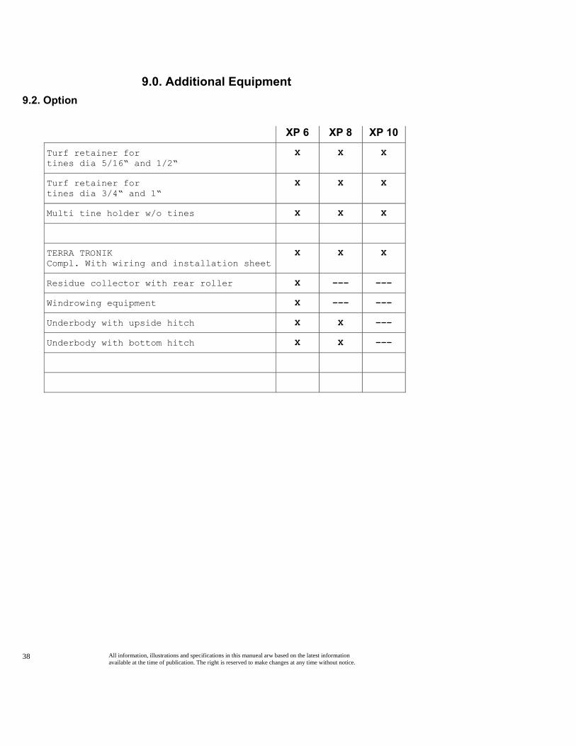
9.0. Additional Equipment 9.2. Option
XP 6 XP 8 XP 10
Turf retainer for tines dia 5/16“ and 1/2“
X X X
Turf retainer for tines dia 3/4“ and 1“
X X X
Multi tine holder w/o tines X X X
TERRA TRONIK Compl. With wiring and installation sheet
X X X
Residue collector with rear roller X --- ---
Windrowing equipment X --- ---
Underbody with upside hitch X X ---
Underbody with bottom hitch X X ---

All information, illustrations and specifications in this manueal arw based on the latest information available at the time of publication. The right is reserved to make changes at any time without notice.
39
10.0. Specifications 10.1.1. Technical details with Typ XP 6
A Height up to connection of lower guide rod under 28 in.
B Height up to connection of lower guide rod topside 32 in.
C Height up to middle of connection of upper guide rod 50 in.
D Height up to connection 39 in.
E Machine length, back roller included 52 in.
F Machine width, hoop guard included 85 in.
G Frame width 67 in.
H Machiune height in parking position 64 in.
K Diameter of front roller 9 in.
L Diameter of back roller 6 in.
Distance between mid guide rod connector and front end power take-off shaft
4 in.
Working width 63 in.
Weight 2116 Lb.
Max. tine length 16 in.
Max. working depth, tines included 16 in.
Max. working depth, hollow tines included 10 in.
Min. power required for tractor 17 (23)
KW (HP)
Min. lifting power at lower guide rod (standard version) 2646 lb.
Step of power take-off shaft tractor 540 rpm
* Length of machine with windrowing equipment 81 in.

All information, illustrations and specifications in this manueal arw based on the latest information available at the time of publication. The right is reserved to make changes at any time without notice.
40
10.0. Specifications 10.1.1. Technical details with Typ XP 6
415.39

All information, illustrations and specifications in this manueal arw based on the latest information available at the time of publication. The right is reserved to make changes at any time without notice.
41
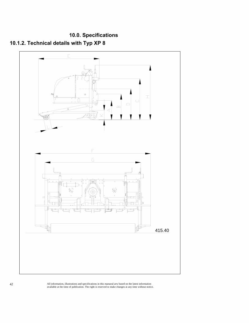
10.0. Specifications 10.1.2. Technical details with Typ XP 8
A Height up to connection of lower guide rod under 28 in.
B Height up to connection of lower guide rod topside 32 in.
C Height up to middle of connection of upper guide rod 50 in.
D Height up to connection 39 in.
E Machine length, back rolll included 52 in.
F Machine width, hoop guard included 104 in.
G Frame width 91 in.
H Machiune height in parking position 64 in.
K Diameter of front roller 9 in.
L Diameter of back roller 6 in.
Distance between mid guide rod connector and front end power take-off shaft
4 in.
Working width 83 in.
Weight 2646 lb.
Max. tine length 16 in.
Max. working depth, tines included 16 in.
Max. working depth, hollow tines included 10 in.
Min. power required for tractor 22 30
KW HP
Min. lifting power at lower guide rod (standard version) 3086 lb.
Step of power take-off shaft tractor 540 rpm
Length of machine with windrowing equipment 81 In.
All information, illustrations and specifications in this manueal arw based on the latest information available at the time of publication. The right is reserved to make changes at any time without notice.
42
10.0. Specifications 10.1.2. Technical details with Typ XP 8
415.40

All information, illustrations and specifications in this manueal arw based on the latest information available at the time of publication. The right is reserved to make changes at any time without notice.
43
10.0. Specifications 10.1.3. Technical details with Typ XP 10
A Height up to connection of lower guide rod under 28 in.
B Height up to connection of lower guide rod topside 32 in.
C Height up to middle of connection of upper guide rod 50 in.
D Height up to connection 39 in.
E Machine length, back rolll included 52 in.
F Machine width, hoop guard included 124 in.
G Frame width 106 in.
H Machiune height in parking position 64 in.
K Diameter of front roller 9 in.
L Diameter of back roller 6 in.
Distance between mid guide rod connector and front end power take-off shaft
4 in.
Working width 102 in.
Weight 3175 lb.
Max. tine length 16 in.
Max. working depth, tines included 16 in.
Max. working depth, hollow tines included 10 in.
Min. power required for tractor 30 (40)
KW (HP)
Min. lifting power at lower guide rod (standard version) 3748 lb.
Step of power take-off shaft tractor 540 rpm
* Length of machine with windrowing equipment 81 in.

All information, illustrations and specifications in this manueal arw based on the latest information available at the time of publication. The right is reserved to make changes at any time without notice.
44
10.0. Specifications 10.1.3. Technical details with Typ XP 10
415.41

All information, illustrations and specifications in this manueal arw based on the latest information available at the time of publication. The right is reserved to make changes at any time without notice.
45
10.0. Specifications 10.2. Speed of the Power Take-off Shaft
Speed of power take-off = number of holes per tine:
Gear speed
300 350 400 450 500 540
I 80 84 107 121 134 145
II 92 107 122 138 153 165
III 104 121 139 156 173 187
10.3. The hole Distances (Standard Values, in mm) The hole distances depend on: • the speed of the power take-off shaft and, • the driving speed.
Driving speed
mile/hour 0.0 0.6 0.9 1.2 1.6
Speed of power take-off
Gear Speed
Gear Speed
Gear Seed
Gear Speed
Gear Speed
shaft I II III I II III I II III I II III I II III
300 rpm 101 90 80 208 181 160 312 271 240 416 362 320 520 452 400
350 rpm 88 78 69 177 156 137 266 233 206 354 311 275 442 389 344
400 rpm 78 68 60 156 136 120 233 205 180 311 273 239 389 341 299
450 rpm 69 60 53 138 121 107 206 181 160 275 241 214 344 301 267
500 rpm 62 54 48 124 109 96 186 163 144 248 217 192 310 271 240
540 rpm 57 50 44 115 101 89 172 151 133 230 202 178 287 252 222
Speed of Power Take-off Shaft (rpm)
All information, illustrations and specifications in this manueal arw based on the latest information available at the time of publication. The right is reserved to make changes at any time without notice.
46
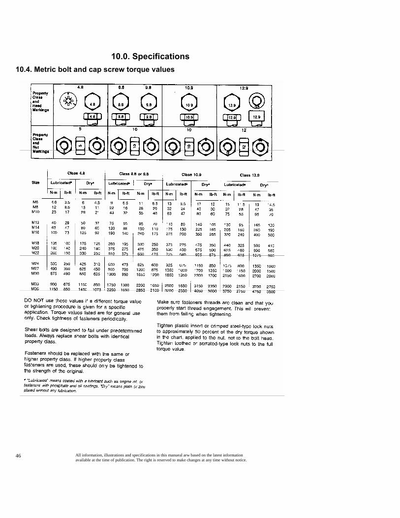
10.0. Specifications 10.4. Metric bolt and cap screw torque values
All information, illustrations and specifications in this manueal arw based on the latest information available at the time of publication. The right is reserved to make changes at any time without notice.
47
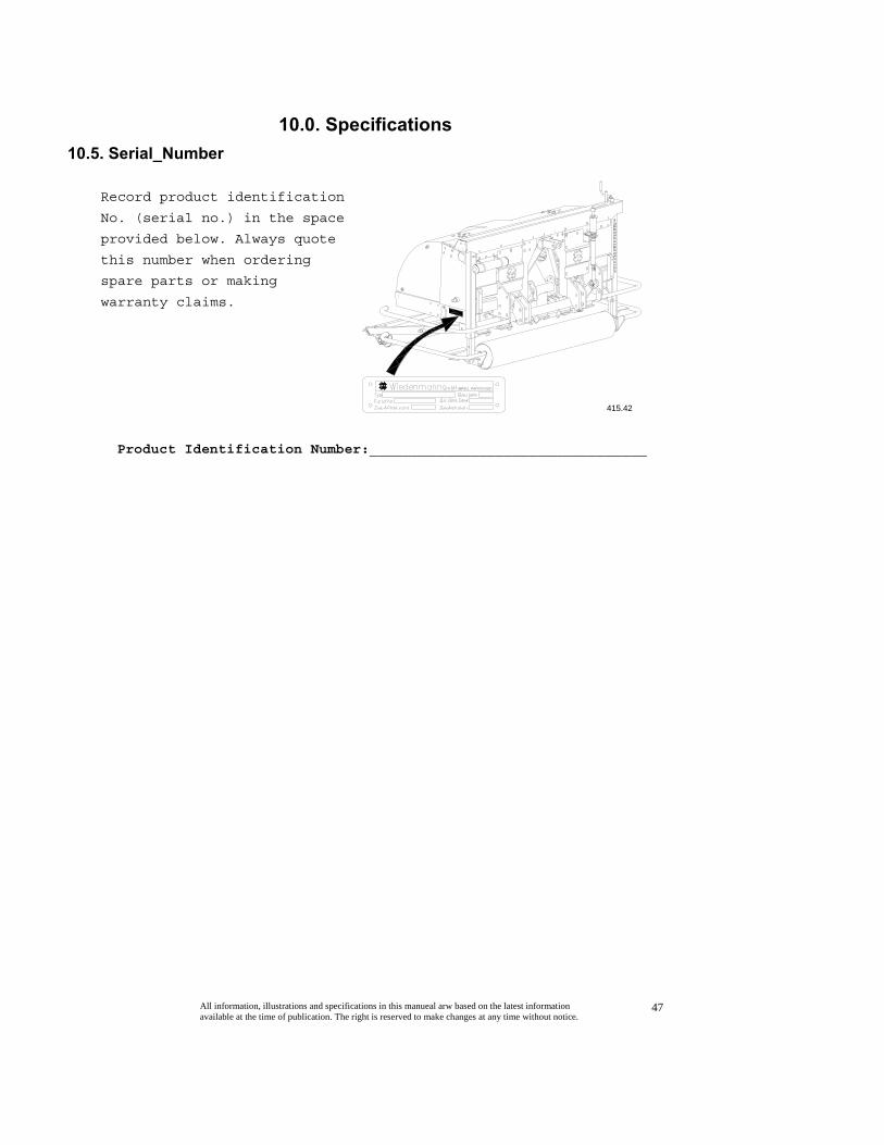
10.0. Specifications 10.5. Serial_Number
Record product identification
No. (serial no.) in the space
provided below. Always quote
this number when ordering
spare parts or making
warranty claims.
Product Identification Number:_________________________________
415.42