Embed Size (px)
Citation preview
prowirl 70Vortex Flow Measuring System
Operating Manual
BA 018D/06/en/03.97Nr. 50072931
Valid as of software version1.1.XX
Nothing beats know-how
Endress Hauser
Safety Instructions
Warning!Please observe without fail the safety instructions in Chapter 1 (page 5).
Documentation for Ex instruments
Instruments which are used in the explosion hazardous areaare supplied with a separate “Ex documentation”, which is anintegral part of this Operating Manual.
The instructions and connected loads provided in thissupplement must absolutely be observed.
An appropriate icon is shown on the front of this documentaccording to the approval given and the test centre.
ba01
8y82
Safety Instructions Prowirl 70
2 Endress+Hauser
ContentsContents
Safety Instructions . . . . . . . . . 2
1 Safety Instructions . . . . . . . . 51.1 Correct Usage . . . . . . . . . . . 51.2 Dangers and Notes . . . . . . . . . 51.3 Personnel for Installation, Start-up and Operation . . . . . . . . 51.4 Repairs, Dangerous Chemicals . . . . . 61.5 Technical Improvements . . . . . . . 6
2 System Description . . . . . . . 72.1 Fields of application . . . . . . . . . 72.2 Measuring Principle . . . . . . . . . 72.3 Prowirl 70 Measuring System . . . . . 8
3 Mounting and Installation . . . 113.1 General Information . . . . . . . . . 113.2 Installation . . . . . . . . . . . . . 133.3 Mounting the Meter Body . . . . . . . 163.4 Electronics Housing/Local Display (Mounting/Rotating) . . . . . . . . . 18
4 Electrical Connection . . . . . 214.1 General Information . . . . . . . . . 214.2 Connecting the Transmitter . . . . . . 214.3 Wiring Diagrams . . . . . . . . . . 214.4 Cable Connection . . . . . . . . . . 234.5 Commissioning . . . . . . . . . . . 24
5 Operation (local display, pushbuttons) . . . 25
5.1 Display and Operating Elements . . . . 255.2 Selecting Functions and Changing Parameters . . . . . . . . 26
6 Functions . . . . . . . . . . . 31
7 Interfaces . . . . . . . . . . . 477.1 HART® . . . . . . . . . . . . . . 477.2 INTENSOR . . . . . . . . . . . . . 50
8 Troubleshooting . . . . . . . . 538.1 System Fault Indication . . . . . . . . 538.2 Error Check List and Correcting Faults . . 538.3 Repairs and Dangerous Chemicals . . . 548.4 Maintenance . . . . . . . . . . . . 54
9 Technical Data . . . . . . . . . 559.1 Dimensions, Weights . . . . . . . . 559.2 Pressure/Temperature Load Diagrams . 609.3 Technical Data: Sensor, Transmitter . . . 619.4 Measuring Ranges . . . . . . . . . 63
Index . . . . . . . . . . . . . . 65
Prowirl 70 Contents
Endress+Hauser 3

Prowirl 70
4 Endress+Hauser
1 Safety Instructions
1.1 Correct Usage
• Prowirl 70 is only to be used for measuring the flow of gas, steam and liquids.• The manufacturer assumes no liability for damage caused by incorrect use of the
instrument.
1.2 Dangers and Notes
All instruments are designed to meet state-of-the-art safety requirements, have beentested, and have left the works in an operationally perfectly safe condition. Thedevices were developed according to EN 61010 “Protection Measures for ElectronicEquipment for Measurement, Control, Regulation and Laboratory Procedures”. A hazardous situation may occur if the flowmeter is not used for the purpose it wasdesigned for or is used incorrectly. Please carefully note the information provided inthis Operating Manual indicated by the pictograms:
Warning!A “warning” indicates actions or procedures which, if not performed correctly, maylead to personal injury or a safety hazard.Please strictly observe the instructions supplied and proceed carefully.
Caution!A “caution” indicates actions or procedures which, if not performed correctly, maylead to faulty operation or destruction of the instrument.Please strictly observe the respective instructions.
Note!A “note” indicates actions or procedures which, if not performed correctly, mayindirectly affect operation or lead to an unexpected instrument response.
1.3 Personnel for Installation, Start-up and Operation
• Mounting, electrical installation, start-up and maintenance of the instrument mayonly be carried out by trained personnel authorized by the operator of the facility.Personnel must absolutely and without fail read and understand this OperatingManual before carrying out its instructions.
• The instrument may only be operated by personnel who are authorized and trainedby the operator of the facility. All instructions in this manual are to be observed without fail.
• In case of corrosive fluids, the resistance of the material of all wetted parts such asmeasuring pipe, bluff body, sensor and gaskets is to be verified (for wetted partsmaterials, see Chapter 9). This also applies to fluids used to clean the Prowirlflowmeter.
• The installer has to make sure that the measuring system is correctly wired upaccording to the wiring diagrams. The measuring system is to be grounded.
• Please observe all provisions valid for your country and pertaining to opening andrepair of electrical devices.
.
Prowirl 70 1 Safety Instructions
Endress+Hauser 5
1.4 Repairs, Dangerous Chemicals
The following procedures must be carried out before a Prowirl 70 is sent toEndress+Hauser for repair:• A note must always be enclosed with the instrument, containing a description of the
fault, the application, and the chemical and physical properties of the fluids.• Remove all residue which may be present. Pay special attention to the gasket grooves
and crevices where fluid may be present. This is especially important if the fluid isdangerous to health, e.g. corrosive, poisonous, carcinogenic, radioactive, etc.
• No instrument should be returned to us without all dangerous material beingremoved first (e.g. in scratches or diffused through plastic).
Incomplete cleaning of the instrument may result in cost for waste disposal or causeharm to personnel (burns, etc). Any costs arising from this will be charged to theowner of the instrument.
1.5 Technical Improvements
The manufacturer reserves the right to modify technical data without prior notice.Your local E+H Sales Office will supply you with all current information and anyupdates to this Operating Manual.
1 Safety Instructions Prowirl 70
6 Endress+Hauser
2 System Description
2.1 Fields of application
The Prowirl 70 vortex flowmeter measures the volumetric flow of fluids having widelydiffering characteristics:• Saturated steam• Superheated steam• Gases• Low-viscosity liquids
Applications include:• Energy production, heat supplies• Chemicals and petrochemicals• Food processing• OEM
Prowirl measures the volumetric flow at process conditions. If the process pressureand temperature are constant, Prowirl can be programmed to display or output theflowrate in mass, energy or corrected volume units.In cases where process conditions are changing, the universal E+H CompartDXF 351 flow computer calculates these values continuously using signals fromProwirl and from additional pressure and temperature transmitters.
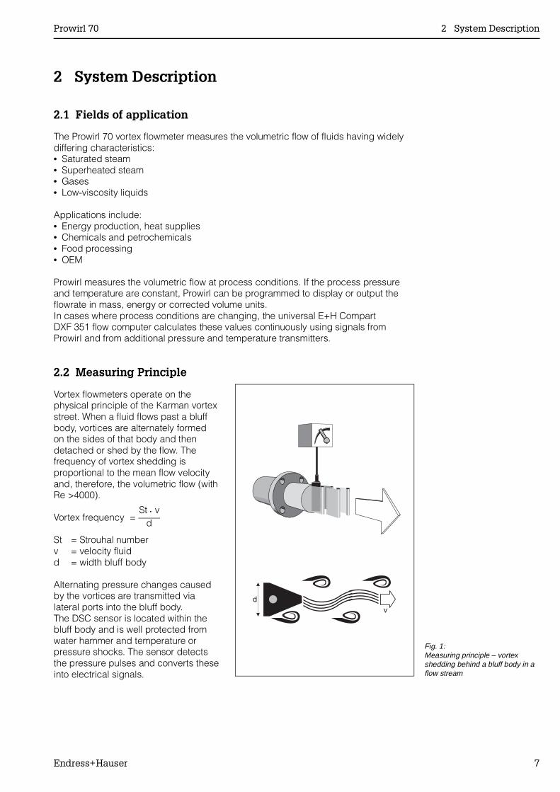
2.2 Measuring Principle
Vortex flowmeters operate on thephysical principle of the Karman vortexstreet. When a fluid flows past a bluffbody, vortices are alternately formedon the sides of that body and thendetached or shed by the flow. Thefrequency of vortex shedding isproportional to the mean flow velocityand, therefore, the volumetric flow (withRe >4000).
Vortex frequency = St • v
d
St = Strouhal numberv = velocity fluidd = width bluff body
Alternating pressure changes causedby the vortices are transmitted vialateral ports into the bluff body.The DSC sensor is located within thebluff body and is well protected fromwater hammer and temperature orpressure shocks. The sensor detectsthe pressure pulses and converts theseinto electrical signals.
Fig. 1:Measuring principle – vortexshedding behind a bluff body in aflow stream
Prowirl 70 2 System Description
Endress+Hauser 7
The sensor amplifier processes the sinusoidal sensor signal into a flow-proportionalpulse frequency. This is then converted by the transmitter (or flow computer) into astandard output signal.
The same sensor and electronics are used for all nominal diameters and fluids.The sensor signal is galvanically isolated in the preamplifier from the output signal.
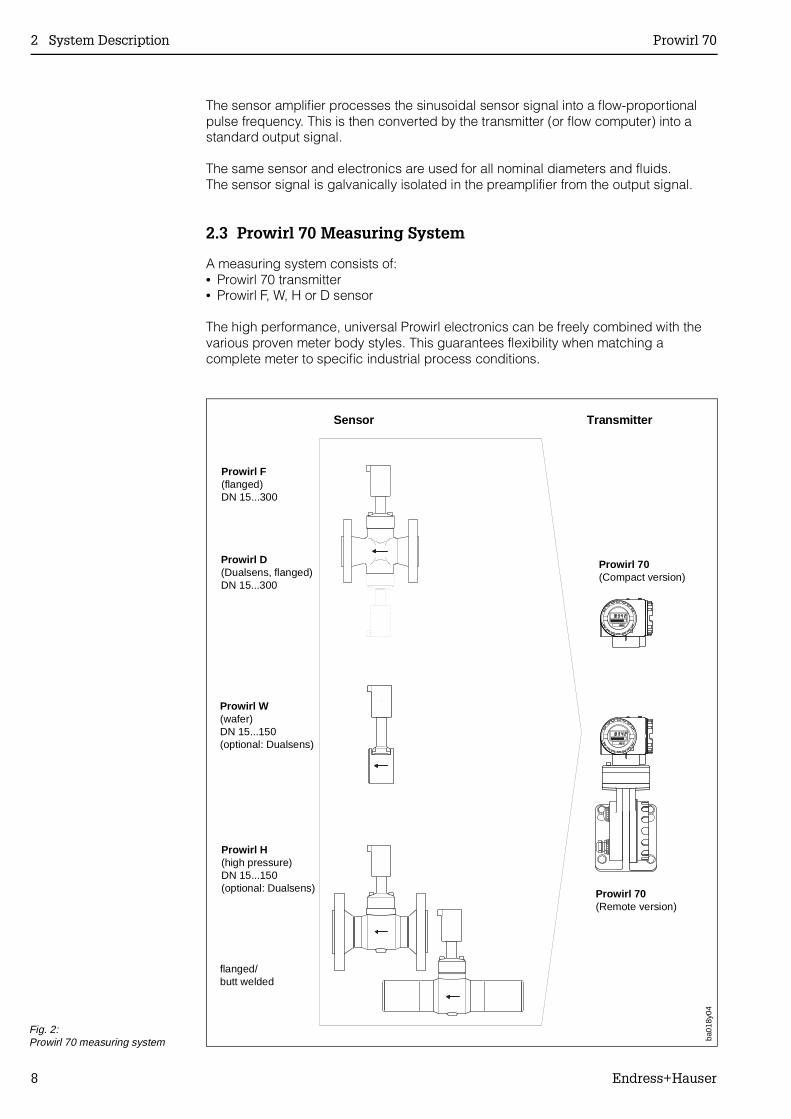
2.3 Prowirl 70 Measuring System
A measuring system consists of:• Prowirl 70 transmitter• Prowirl F, W, H or D sensor
The high performance, universal Prowirl electronics can be freely combined with thevarious proven meter body styles. This guarantees flexibility when matching acomplete meter to specific industrial process conditions.
Prowirl F(flanged)DN 15...300
TransmitterSensor
Prowirl W(wafer)DN 15...150(optional: Dualsens)
Prowirl 70(Remote version)
flanged/butt welded
Prowirl 70(Compact version)
Prowirl H(high pressure)DN 15...150(optional: Dualsens)
ba01
8y04
Prowirl D(Dualsens, flanged)DN 15...300
Fig. 2:Prowirl 70 measuring system
2 System Description Prowirl 70
8 Endress+Hauser
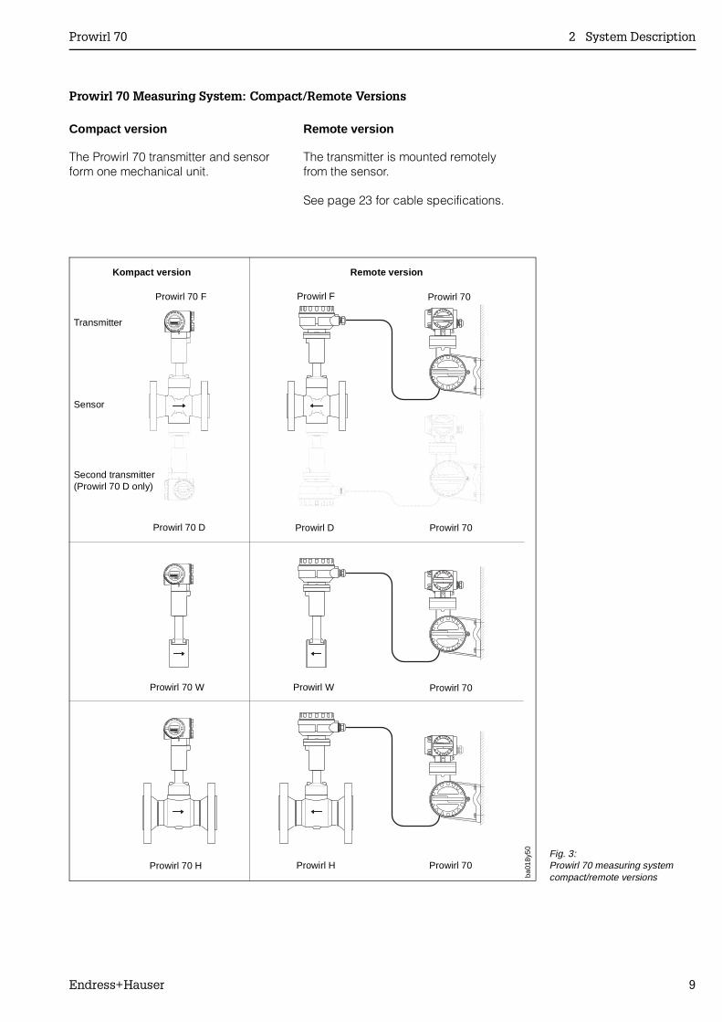
Prowirl 70 Measuring System: Compact/Remote Versions
Compact version Remote version
The Prowirl 70 transmitter and sensorform one mechanical unit.
The transmitter is mounted remotelyfrom the sensor.
See page 23 for cable specifications.
Prowirl 70 F Prowirl F Prowirl 70
Prowirl 70 D Prowirl D Prowirl 70
Prowirl 70 W Prowirl W Prowirl 70
Prowirl 70 H Prowirl H Prowirl 70
Transmitter
Sensor
Second transmitter(Prowirl 70 D only)
Kompact version Remote version
ba01
8y50 Fig. 3:
Prowirl 70 measuring systemcompact/remote versions
Prowirl 70 2 System Description
Endress+Hauser 9
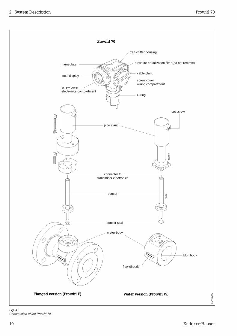
transmitter housing
cable gland
screw coverwiring compartment
O-ring
set screw
connector totransmitter electronics
pipe stand
sensor seal
sensor
Flanged version (Prowirl F)
nameplate
local display
flow direction
Wafer version (Prowirl W)
meter body
bluff body
Prowirl 70
ba01
8y05
screw coverelectronics compartment
pressure equalization filter (do not remove)
Fig. 4:Construction of the Prowirl 70
2 System Description Prowirl 70
10 Endress+Hauser
3 Mounting and Installation
Caution!All instructions given in this section are to be observed at all times in order to ensuresafe and reliable operation of the measuring system.
3.1 General Information
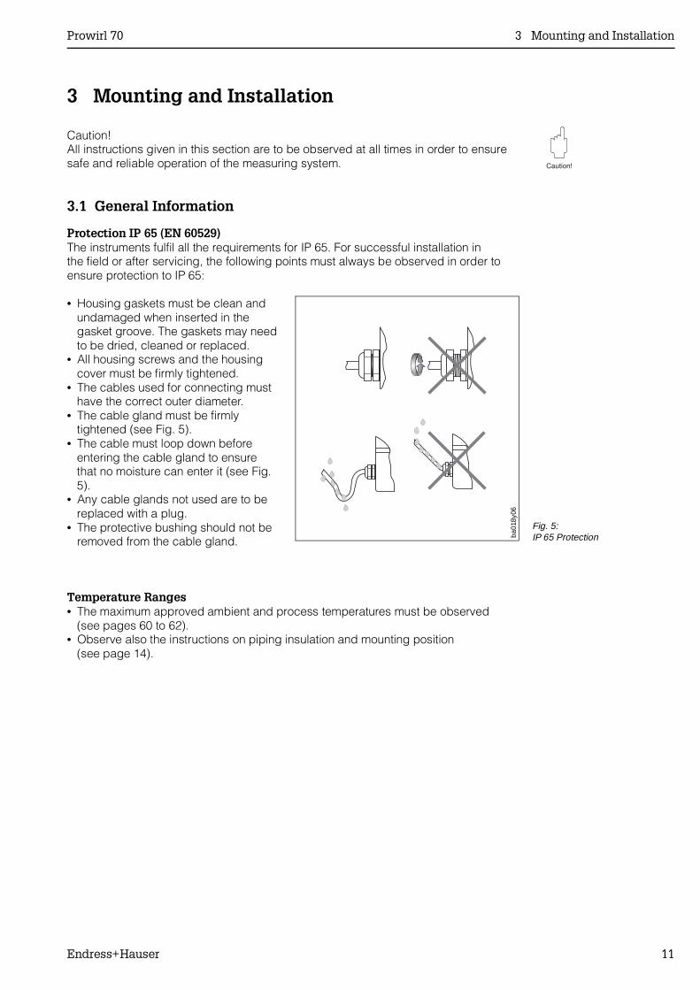
Protection IP 65 (EN 60529)The instruments fulfil all the requirements for IP 65. For successful installation inthe field or after servicing, the following points must always be observed in order toensure protection to IP 65:
• Housing gaskets must be clean andundamaged when inserted in thegasket groove. The gaskets may needto be dried, cleaned or replaced.
• All housing screws and the housingcover must be firmly tightened.
• The cables used for connecting musthave the correct outer diameter.
• The cable gland must be firmlytightened (see Fig. 5).
• The cable must loop down beforeentering the cable gland to ensurethat no moisture can enter it (see Fig.5).
• Any cable glands not used are to bereplaced with a plug.
• The protective bushing should not beremoved from the cable gland.
Temperature Ranges• The maximum approved ambient and process temperatures must be observed
(see pages 60 to 62).• Observe also the instructions on piping insulation and mounting position
(see page 14).
ba01
8y06
Fig. 5:IP 65 Protection
Prowirl 70 3 Mounting and Installation
Endress+Hauser 11
Pressure Pulses/Measuring AccuracyReciprocating pumps and compressors create strong changes in process pressurein the piping and thus cause additional measuring errors. These pressure pulses mustbe reduced by appropriate measures, e.g.:• using expansion tanks (for gases and liquids),• with compressed air chambers (for liquids),• with inlet expanders (for gas),• with a more suitable mounting location.
Note!The ratio between pressure pulsation ∆Pp and the vortex intensity ∆Pw is in direct relation to the resulting measuring error. The ratio ∆Pp/∆Pw should not exceed 15 sothat the measuring accuracy for the Prowirl measuring system is always maintained:
∆Pw = 1,47 ⋅ 10-5 ⋅ ρ ⋅ v2 and∆ Pp
∆ Pw <15
∆Pp = pressure pulsation [bar]∆Pw = vortex intensity [bar]ρ = density of the liquid [kg/m3]v = mean flow velocity [m/s]
Minimum Back Pressure and Cavitation with LiquidsShocks caused by cavitation* can substantially disturb (liquid) measurement or evenmake measurement impossible. This may result in damage in the area of the bluffbody.To prevent cavitation, a sufficiently high back pressure must be maintained at theflowmeter outlet. The minimum back pressure is determined by the following formula:
p ≥ 2.6 ∆p + 1.25 pD
p = minimum pipeline pressure [bar abs.], 5 x DN downstream of the sensor∆p = pressure drop across the meter body [bar]pD = liquid vapour pressure at operating conditions [bar abs.]
(* Cavitation: A sudden pressure drop due to a throat in the pipe may cause a flowingliquid to locally fall below its vapour pressure and therefore allow bubbles to form.These bubbles implode downstream with increasing liquid pressure leading to theabove mentioned shocks)
Additional Notes !• When measuring liquids, the meter should be installed where the pipeline is
always full (e.g. in vertical pipelines).• Free-standing pipes subject to strong vibration should be firmly attached or
supported upstream and downstream of the meter.• A gas separator should be used in the pipeline if a liquid tends to form gas bubbles.• Ensure that condensate can be removed from steam pipes.
3 Mounting and Installation Prowirl 70
12 Endress+Hauser
3.2 Installation
The following minimum installation recommendations are to be observed wheninstalling the Prowirl 70 vortex flowmeter in the pipeline. In order to achieve optimummeasuring accuracy, the inner diameters of the flowmeter and the process pipingshould be identical.
Inlet and Outlet SectionsAn undisturbed flow profile is aprerequisite for accurate vortex flowmeasurement. The minimumrecommendations for clear pipework oneither side of the flowmeter are:• Inlet section: min. 10 x DN• Outlet section: min. 5 x DN
If flow disturbances such as pipeelbows, reducers, expanders, etc. arelocated upstream of the measuringpoint, then longer inlet sections arerequired (see Fig. 6).This also applies to valves. Whereverpossible, they should be installeddownstream of the sensor.
Note!If two or more flow disturbancesare located upstream, then the longestinlet pipe section is recommended. Insuch cases, a flow conditioner shouldbe used.
Flow ConditionerWith limited space and large pipes, it isnot always possible to have the inletsections given above. The speciallydeveloped perforated plate flow rectifierreduces the inlet path to 10 x DN.The flow rectifier is held between twopiping flanges and centred with theflange bolts. It rectifies distorted flowprofiles efficiently with very littlepressure loss:
∆p [mbar] = 0.0085 ⋅ ρ [kg/m3] ⋅ v2 [m/s]
• Example with steam:p = 10 bar abs.; t = 240 °C ⇒ ρ = 4.39 kg/m3
v = 40 m/s∆p= 0.0085 ⋅ 4.39 kg/m3 ⋅ (40 m/s)2 =
59.7 mbar
• Example with H2O condensate (80 °C):ρ = 965 kg/m3; v = 2.5 m/s∆p= 0.0085 ⋅ 965 kg/m3 ⋅ (2.5 m/s)2 =
51.3 mbar
Inlet Outlet
Reducer
Expander
90° elbowor T-piece
2 x 90° elbows
2 x 90° elbows3-dimensional
Control valve
With flowconditioner
ba01
8y07 Fig. 6:
Inlet and outlet pipingrequirements
Prowirl 70 3 Mounting and Installation
Endress+Hauser 13
Installation SiteThe Prowirl measuring system can bemounted in any position in the pipingalthough for extremes of processtemperatures, the following orientationsare recommended:
High process temperatures (e.g. steam):• Horizontal pipeline: install according
to C or D• Vertical pipeline: install according to A,
with flow direction upwards for liquids,to ensure a full pipe.
Low process temperatures (cryogenics):• Horizontal pipeline: install according
to B or D• Vertical pipeline: install according to A,
with flow direction upwards for liquids,to ensure a full pipe.
Heat may accumulate where hotpipelines are mounted directly undera roof (Ambient temperatures seepage 62).Ensure flow direction corresponds to thearrow on the meter body.
Pressure and temperature transmittersare to be positioned downstream ofProwirl so that optimum vortex sheddingis not affected (see adjacent figure).
Pipeline InsulationPipeline insulation is necessary toprevent energy loss in hot andcryogenic processes. When insulatingensure that sufficient pipe stand surfacearea isexposed. This applies to both compactand remote versions. The exposed areaserves as a radiator and protects theelectronics from extreme heat (or fromexcessive cooling).
B
C
D
A
ba01
8y08Fig. 7:
Orientation and processtemperature
PT
ba01
8y09Fig. 8:
Pressure and temperaturetransmitter location
ba01
8y10
Wafer version Flanged version
Fig. 9:Pipeline insulation
3 Mounting and Installation Prowirl 70
14 Endress+Hauser
Minimum SpacingWhen servicing or connecting the"Flowjack" simulator, it is necessary toremove the Prowirl transmitter housingfrom the pipe stand (→ securing screw,see Fig. 4). When installing in thepiping, observe the following cablelengths and minimum space:• Minimum space above the housing:
12 cm; all other sides 10 cm• Cable length required: L + 15 cm
Figure 11 illustrates the minimumspacing requirements for the remoteversion.
Caution!Removing the transmitter from the pipe stand is to be carried out by E+Hservice personnel only! Additional information is given in the Prowirl servicemanual.
min. 12 cm
ba01
8y11 Fig. 10:
Minimum spacing and cablelengths
min. 120 mm
ba01
8y51
min. 50 mm
Fig. 11:Minimum spacing and cablelengths
Prowirl 70 3 Mounting and Installation
Endress+Hauser 15
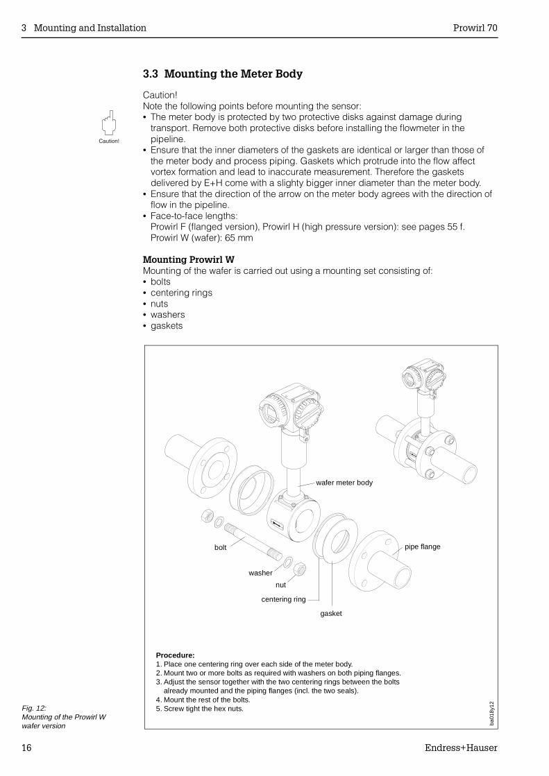
3.3 Mounting the Meter Body
Caution!Note the following points before mounting the sensor:• The meter body is protected by two protective disks against damage during
transport. Remove both protective disks before installing the flowmeter in thepipeline.
• Ensure that the inner diameters of the gaskets are identical or larger than those ofthe meter body and process piping. Gaskets which protrude into the flow affectvortex formation and lead to inaccurate measurement. Therefore the gasketsdelivered by E+H come with a slighty bigger inner diameter than the meter body.
• Ensure that the direction of the arrow on the meter body agrees with the direction offlow in the pipeline.
• Face-to-face lengths:Prowirl F (flanged version), Prowirl H (high pressure version): see pages 55 f.Prowirl W (wafer): 65 mm
Mounting Prowirl WMounting of the wafer is carried out using a mounting set consisting of:• bolts• centering rings• nuts• washers• gaskets
Procedure:1. Place one centering ring over each side of the meter body.2. Mount two or more bolts as required with washers on both piping flanges.3. Adjust the sensor together with the two centering rings between the bolts
already mounted and the piping flanges (incl. the two seals).4. Mount the rest of the bolts.5. Screw tight the hex nuts.
washer
gasket
wafer meter bodyba
018y
12
bolt
centering ring
nut
pipe flange
Fig. 12:Mounting of the Prowirl Wwafer version
3 Mounting and Installation Prowirl 70
16 Endress+Hauser

Mounting Prowirl H (butt-weld version)The following must be observed when welding the high pressure butt weld versioninto the piping:• maximum 7000 Joule/cm• intermediate temperature <30 °C
Caution!All regulations concerning welding and materials used are to be observed.
Prowirl 70 3 Mounting and Installation
Endress+Hauser 17
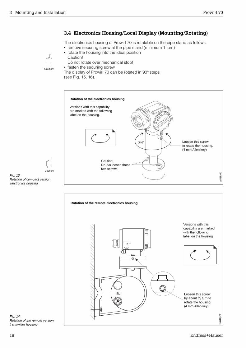
3.4 Electronics Housing/Local Display (Mounting/Rotating)
The electronics housing of Prowirl 70 is rotatable on the pipe stand as follows:• remove securing screw at the pipe stand (minimum 1 turn)• rotate the housing into the ideal position
Caution!Do not rotate over mechanical stop!
• fasten the securing screwThe display of Prowirl 70 can be rotated in 90° steps(see Fig. 15, 16).
Rotation of the electronics housing
Versions with this capabilityare marked with the followinglabel on the housing.
ba01
8y41
Loosen this screwto rotate the housing.(4 mm Allen key)
Caution!Do not loosen thosetwo screws
Fig. 13:Rotation of compact versionelectronics housing
ba01
8y52
Rotation of the remote electronics housing
Versions with thiscapability are markedwith the followinglabel on the housing.
Loosen this screwby about 1⁄2 turn torotate the housing.(4 mm Allen key)
Fig. 14:Rotation of the remote versiontransmitter housing
3 Mounting and Installation Prowirl 70
18 Endress+Hauser
➊➋
➌
➍
m /h3
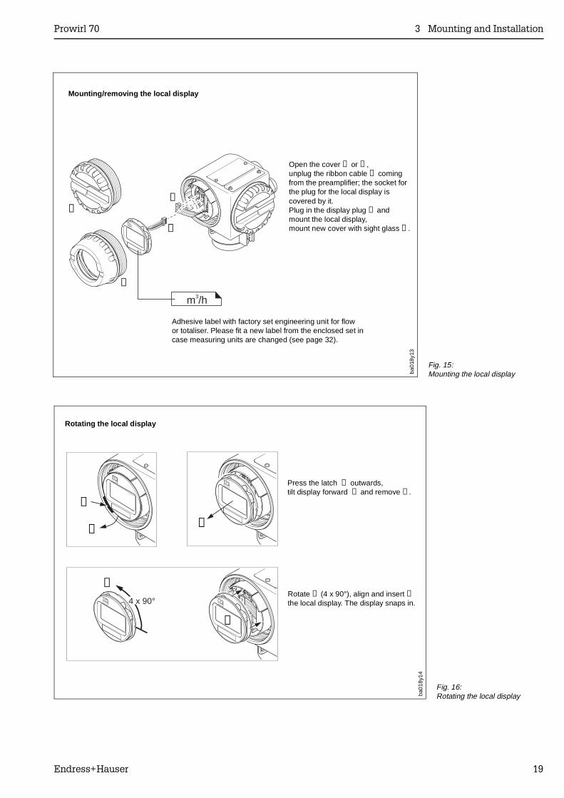
Mounting/removing the local display
Open the cover ➊ or ➍,unplug the ribbon cable ➋ comingfrom the preamplifier; the socket forthe plug for the local display iscovered by it.Plug in the display plug ➌ and mount the local display,mount new cover with sight glass ➍.
Adhesive label with factory set engineering unit for flowor totaliser. Please fit a new label from the enclosed set incase measuring units are changed (see page 32).
ba01
8y13
Fig. 15:Mounting the local display
4 x 90°
➊
➋➌
➍
➎
Press the latch ➊ outwards,tilt display forward ➋ and remove ➌.
Rotating the local display
Rotate ➍ (4 x 90°), align and insert ➎the local display. The display snaps in.
ba01
8y14
Fig. 16:Rotating the local display
Prowirl 70 3 Mounting and Installation
Endress+Hauser 19

Prowirl 70
20 Endress+Hauser
4 Electrical Connection
4.1 General Information
The information in Section 2.1 must be observed in order to maintain IP 65 protection.
4.2 Connecting the Transmitter
Caution!• All relevant national electrical regulations must be observed.• For installation of Prowirl 70 in a hazardous area please read the separate
operating manual EX002...• The power supply voltage is max. 30 V DC.
Procedure:1. Unscrew the wiring compartment cover.2. Feed the power and signal cables through the cable gland.3. Wire up according to the wiring diagrams (see diagram in the screw cover or
Fig. 17, 18, 19)4. Screw the wiring compartment cover securely back onto the transmitter housing.
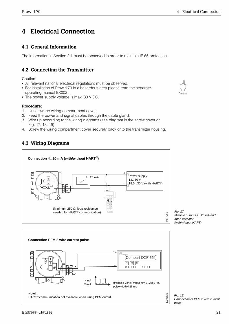
4.3 Wiring Diagrams
Power supply12...30 V18.5...30 V (with HART®)
(Minimum 250 Ω loop resistanceneeded for HART® communication)
Connection 4...20 mA (with/without HART ®)
ba01
8y56
4...20 mA
Fig. 17:Multiple outputs 4...20 mA and open collector (with/without HART)
Connection PFM 2 wire current pulse
ba01
8y57
4 mA20 mA unscaled Vortex frequency 1...2850 Hz,
pulse width 0,18 ms
Note!HART® communication not available when using PFM output. Fig. 18:
Connection of PFM 2 wire current pulse
Prowirl 70 4 Electrical Connection
Endress+Hauser 21
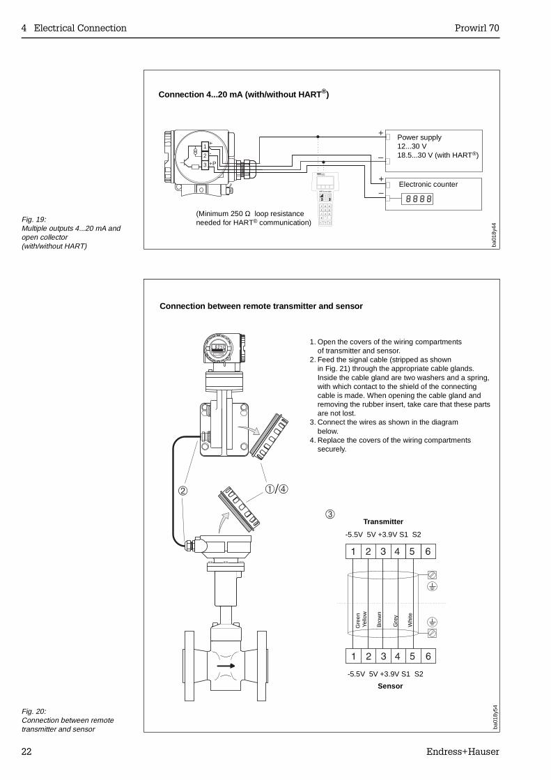
1 +
2 -
3 +P
IO 8888
+
–
+
–
Power supply12...30 V18.5...30 V (with HART®)
(Minimum 250 Ω loop resistanceneeded for HART® communication)
Connection 4...20 mA (with/without HART ®)
Electronic counter
ba01
8y44
Fig. 19:Multiple outputs 4...20 mA and open collector (with/without HART)
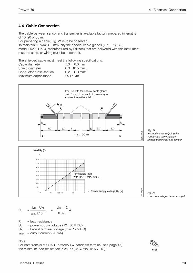
1. Open the covers of the wiring compartmentsof transmitter and sensor.
2. Feed the signal cable (stripped as shownin Fig. 21) through the appropriate cable glands.Inside the cable gland are two washers and a spring,with which contact to the shield of the connectingcable is made. When opening the cable gland andremoving the rubber insert, take care that these partsare not lost.
3. Connect the wires as shown in the diagrambelow.
4. Replace the covers of the wiring compartmentssecurely.
Connection between remote transmitter and sensor
Transmitter
ba01
8y54
Sensor
-5.5V 5V +3.9V S1 S2
-5.5V 5V +3.9V S1 S2
Gre
enYe
llow
Bro
wn
Gre
y
Whi
te
Fig. 20:Connection between remotetransmitter and sensor
4 Electrical Connection Prowirl 70
22 Endress+Hauser
4.4 Cable Connection
The cable between sensor and transmitter is available factory prepared in lengthsof 10, 20 or 30 m.For preparing a cable, Fig. 21 is to be observed.To maintain 10 V/m RFI-immunity the special cable glands (U71, PG13.5,model 2522211s04, manufactured by Pflitsch) that are delivered with this instrumentmust be used, or wiring must be in conduit.
The shielded cable must meet the following specifications:Cable diameter 5.0... 8.0 mmShield diameter 8.0...10.5 mmConductor cross section 0.2... 6.0 mm2
Maximum capacitance 250 pF/m
RL = US – UKl
Imax ⋅ 10−3=
US – 12
0.025 Ω
RL = load resistanceUS = power supply voltage (12...30 V DC)UKl = Prowirl terminal voltage (min. 12 V DC)Imax = output current (25 mA)
Note!For data transfer via HART protocol (→ handheld terminal, see page 47), the minimum load resistance is 250 Ω (US = min. 18.5 V DC). Note!
For use with the special cable glands,strip 5 mm of the cable to ensure goodconnection to the shield.
Power supply voltage US [V]
ba01
8y53
Fig. 21:Instructions for stripping theconnection cable betweenremote transmitter and sensor
Load RL [Ω]
Permissible load (with HART: min. 250 Ω)
ba01
8y24
Fig. 22:Load on analogue current output
Prowirl 70 4 Electrical Connection
Endress+Hauser 23

4.5 Commissioning
Caution!Newly installed piping should always be thoroughly rinsed through before mountingthe meter, to prevent mechanical damage.
Before powering up the meter, the following checks should be carried out:• Installation: Ensure that the directional arrow on the meter body agrees with the
actual flow direction.• Electrical connection: Check electrical connections as shown on page 21 f.• Power supply: Ensure that the power supply voltage does not exceed 30 V DC.
If these checks are successful then switch on the power supply. The instrument isnow ready for use.
4 Electrical Connection Prowirl 70
24 Endress+Hauser
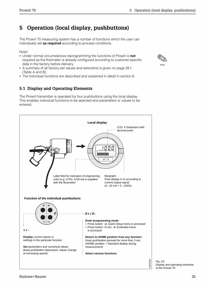
5 Operation (local display, pushbuttons)
The Prowirl 70 measuring system has a number of functions which the user canindividually set as required according to process conditions.
Note!• Under normal circumstances reprogramming the functions of Prowirl is not
required as the flowmeter is already configured according to customer-specificdata in the factory before delivery.
• A summary of all factory-set values and selections is given on page 28 f.(Table A and B).
• The individual functions are described and explained in detail in section 6.
5.1 Display and Operating Elements
The Prowirl transmitter is operated by four pushbuttons using the local display. This enables individual functions to be selected and parameters or values to beentered.
Note!
Local displayLCD: 4 characters withdecimal point
Bargraph:Flow display in % according tocurrent output signal (4...20 mA = 0...100%)
Label field for indication of engineeringunits (e.g. m3/h). A foil set is suppliedwith the flowmeter!
Function of the individual pushbuttons
F+ / F-
Enter programming mode• Press button Quick Setup menu is accessed• Press button >3 sec. Extended menu
is accessed
Return to HOME position from any function:Keep pushbutton pressed for more than 3 sec.(HOME position = Standard display duringmeasurement)
Select various functions
+ / -
Display current values orsettings in the particular function
Set parameters and numerical values(keep pushbutton depressed: values changeat increasing speed)
ba01
8y25 Fig. 23:
Display and operating elementsof the Prowirl 70
Prowirl 70 5 Operation (local display, pushbuttons)
Endress+Hauser 25
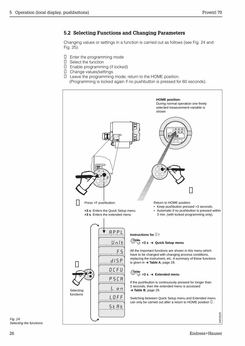
5.2 Selecting Functions and Changing Parameters
Changing values or settings in a function is carried out as follows (see Fig. 24 andFig. 25):
➊ Enter the programming mode➋ Select the function➌ Enable programming (if locked)➍ Change values/settings➎ Leave the programming mode; return to the HOME position. (Programming is locked again if no pushbutton is pressed for 60 seconds).
➎
Return to HOME position:• Keep pushbutton pressed >3 seconds.• Automatic if no pushbutton is pressed within
3 min. (with locked programming only).
Press +F pushbutton:
<3 s: Enters the Quick Setup menu>3 s: Enters the extended menu
Selectingfunctions
HOME position:During normal operation one freelyselected measurement variable isshown
Instructions for ➊!
<3 s Quick Setup menu
All the important functions are shown in this menu whichhave to be changed with changing process conditions,replacing the instrument, etc. A summary of these functionsis given in Table A , page 28.
>3 s Extended menu
If the pushbutton is continuously pressed for longer than3 seconds, then the extended menu is accessed Table B , page 29.
Switching between Quick Setup menu and Extended menucan only be carried out after a return to HOME position ➎.
➊
➋
ba01
8y26
Fig. 24:Selecting the functions
5 Operation (local display, pushbuttons) Prowirl 70
26 Endress+Hauser
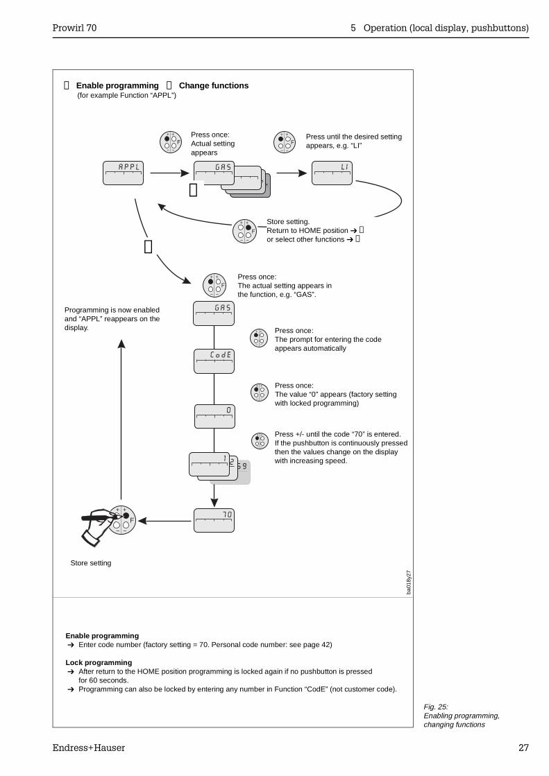
Press once:Actual settingappears
Store setting.Return to HOME position ➎or select other functions ➋
Press once:The actual setting appears inthe function, e.g. “GAS”.
Press once:The value “0” appears (factory settingwith locked programming)
Press once:The prompt for entering the codeappears automatically
Press +/- until the code “70” is entered.If the pushbutton is continuously pressedthen the values change on the displaywith increasing speed.
Enable programming Enter code number (factory setting = 70. Personal code number: see page 42)
Lock programming After return to the HOME position programming is locked again if no pushbutton is pressed
for 60 seconds. Programming can also be locked by entering any number in Function “CodE” (not customer code).
Press until the desired settingappears, e.g. “LI”
Programming is now enabledand “APPL” reappears on thedisplay.
Store setting
➌
➍
ba01
8y27
➌ Enable programming ➍ Change functions (for example Function “APPL”)
Fig. 25:Enabling programming,changing functions
Prowirl 70 5 Operation (local display, pushbuttons)
Endress+Hauser 27
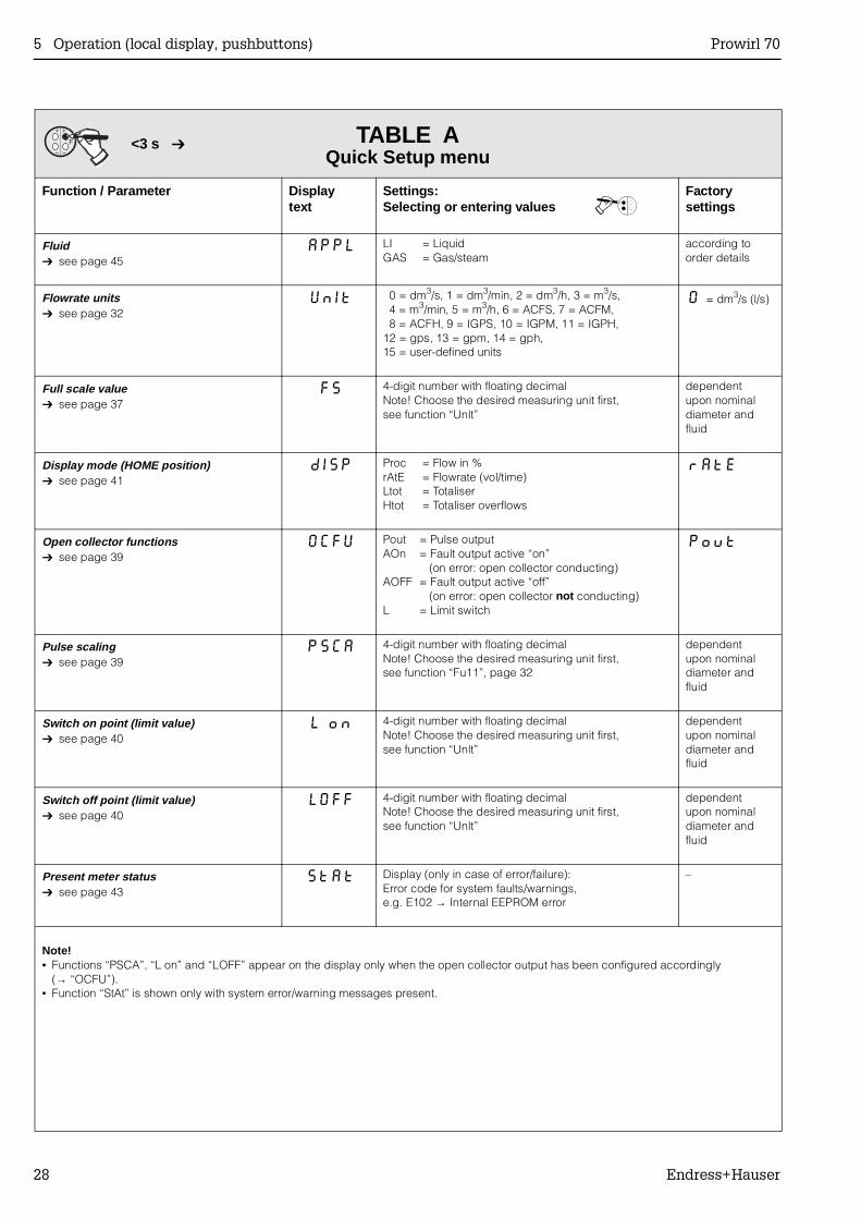
TABLE AQuick Setup menu
Function / Parameter Displaytext
Settings:Selecting or entering values
Factorysettings
Fluid see page 45
APPL LI = LiquidGAS = Gas/steam
according toorder details
Flowrate units see page 32
UnIt 0 = dm3/s, 1 = dm3/min, 2 = dm3/h, 3 = m3/s, 4 = m3/min, 5 = m3/h, 6 = ACFS, 7 = ACFM, 8 = ACFH, 9 = IGPS, 10 = IGPM, 11 = IGPH,12 = gps, 13 = gpm, 14 = gph,15 = user-defined units
0 = dm3/s (l/s)
Full scale value see page 37
FS 4-digit number with floating decimalNote! Choose the desired measuring unit first,see function “Unlt”
dependentupon nominaldiameter andfluid
Display mode (HOME position) see page 41
dISP Proc = Flow in %rAtE = Flowrate (vol/time)Ltot = TotaliserHtot = Totaliser overflows
rAtE
Open collector functions see page 39
OCFU Pout = Pulse outputAOn = Fault output active “on”
(on error: open collector conducting)AOFF = Fault output active “off”
(on error: open collector not conducting)L = Limit switch
Pout
Pulse scaling see page 39
PSCA 4-digit number with floating decimalNote! Choose the desired measuring unit first,see function “Fu11”, page 32
dependentupon nominaldiameter andfluid
Switch on point (limit value) see page 40
L on 4-digit number with floating decimalNote! Choose the desired measuring unit first,see function “Unlt”
dependentupon nominaldiameter andfluid
Switch off point (limit value) see page 40
LOFF 4-digit number with floating decimalNote! Choose the desired measuring unit first,see function “Unlt”
dependentupon nominaldiameter andfluid
Present meter status see page 43
StAt Display (only in case of error/failure):Error code for system faults/warnings,e.g. E102 → Internal EEPROM error
–
Note!• Functions “PSCA”, “L on” and “LOFF” appear on the display only when the open collector output has been configured accordingly
(→ “OCFU”).• Function “StAt” is shown only with system error/warning messages present.
0
<3 s
5 Operation (local display, pushbuttons) Prowirl 70
28 Endress+Hauser
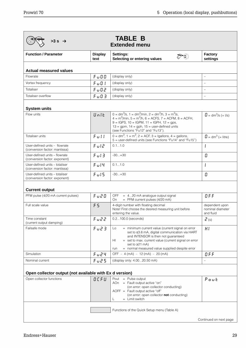
TABLE BExtended menu
Function / Parameter Displaytext
Settings:Selecting or entering values
Factorysettings
Actual measured valuesFlowrate Fu00 (display only) –
Vortex frequency Fu0 i (display only) –
Totaliser Fu02 (display only) –
Totaliser overflow Fu03 (display only) –
System unitsFlow units UnIt 0 = dm3/s, 1 = dm3/min, 2 = dm3/h, 3 = m3/s,
4 = m3/min, 5 = m3/h, 6 = ACFS, 7 = ACFM, 8 = ACFH,9 = IGPS, 10 = IGPM, 11 = IGPH, 12 = gps,13 = gpm, 14 = gph, 15 = user-defined units(see Functions “Fu12” and “Fu13”).
0 = dm3/s (= l/s)
Totaliser units Fui i 0 = dm3, 1 = m3, 2 = ACF, 3 = Igallons, 4 = gallons,5 = user-defined units (see Functions “Fu14” and “Fu15”)
0 = dm3 (= litre)
User-defined units – flowrate(conversion factor: mantissa)
Fui2 0.1...1.0 i
User-defined units – flowrate(conversion factor: exponent)
Fui3 -30...+30 0
User-defined units – totaliser(conversion factor: mantissa)
Fui4 0.1...1.0 i
User-defined units – totaliser(conversion factor: exponent)
Fui5 -30...+30 0
Current outputPFM pulse (4/20 mA current pulses) Fu20 OFF = 4...20 mA analogue output signal
On = PFM current pulses (4/20 mA)OFF
Full scale value FS 4-digit number with floating decimalNote! First choose the desired measuring unit beforeentering the value.
dependent uponnominal diameterand fluid
Time constant(current output damping)
Fu22 0.2...100.0 (seconds) 2 (s)
Failsafe mode Fu23 Lo = minimum current value (current signal on errorset to ≤3.6 mA, digital communication via HART and INTENSOR is then not guaranteed
HI = set to max. current value (current signal on errorset to ≥21 mA)
run = normal measured value supplied despite error
HI
Simulation Fu24 OFF – 4 (mA) – 12 (mA) – 20 (mA) OFFNominal current Fu25 (display only: 4.00...20.50 mA) –
Open collector output (not available with Ex d version)Open collector functions OCFU Pout = Pulse output
AOn = Fault output active “on”(on error: open collector conducting)
AOFF = Fault output active “off”(on error: open collector not conducting)
L = Limit switch
Pout
Functions of the Quick Setup menu (Table A)
Continued on next page
0
>3 s
Prowirl 70 5 Operation (local display, pushbuttons)
Endress+Hauser 29
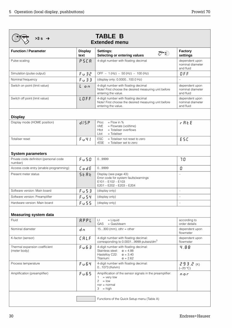
TABLE BExtended menu
Function / Parameter Displaytext
Settings:Selecting or entering values
Factorysettings
Pulse scaling PSCA 4-digit number with floating decimal dependent uponnominal diameterand fluid
Simulation (pulse output) Fu32 OFF – 1 (Hz) – 50 (Hz) – 100 (Hz) OFFNominal frequency Fu33 (display only: 0.0000...100.0 Hz) –
Switch on point (limit value) L on 4-digit number with floating decimalNote! First choose the desired measuring unit beforeentering the value.
dependent uponnominal diameterand fluid
Switch off point (limit value) LOFF 4-digit number with floating decimalNote! First choose the desired measuring unit beforeentering the value.
dependent uponnominal diameterand fluid
DisplayDisplay mode (HOME position) dISP Proc = Flow in %
rAtE = Flowrate (vol/time)Htot = Totaliser overflowsLtot = Totaliser
rAtE
Totaliser reset Fu4 i ESC = Totaliser not reset to zerorESE = Totaliser set to zero
ESC
System parametersPrivate code definition (personal codenumber)
Fu50 0...9999 70
Access code entry (enable programming) CodE 0...9999 0Present meter status StAt Display (see page 43):
Error code for system faults/warnings E101 – E102 – E103E201 – E202 – E203 – E204
–
Software version: Main board Fu53 (display only) –
Software version: Preamplifier Fu54 (display only) –
Hardware version: Main board Fu55 (display only) –
Measuring system dataFluid APPL LI = Liquid
GAS = Gas/steamaccording toorder details
Nominal diameter dn 15...300 (mm), othr = other dependent uponflowmeter
K-factor (sensor) CALF 4-digit number with floating decimal:corresponding to 0.0001...9999 pulses/dm3
dependent uponflowmeter
Thermal expansion coefficient(meter body)
Fu63 4-digit number with floating decimal:Stainless steel: α = 4.88Hastelloy C22: α = 3.40Titanium: α = 2.62
4.88
Process temperature Fu64 4-digit number with floating decimal:0...1073 (Kelvin)
293.2 (K)(~20 °C)
Amplification (preamplifier) Fu65 Amplification of the sensor signals in the preamplifier:1 = very low2 = lownor = normal3 = high
nor
Functions of the Quick Setup menu (Table A)
0
>3 s
5 Operation (local display, pushbuttons) Prowirl 70
30 Endress+Hauser
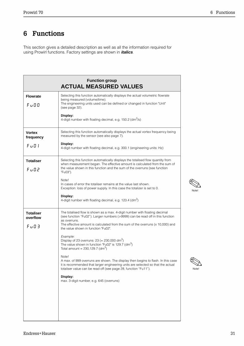
6 Functions
This section gives a detailed description as well as all the information required forusing Prowirl functions. Factory settings are shown in italics .
Function group
ACTUAL MEASURED VALUES
Flowrate
Fu00
Selecting this function automatically displays the actual volumetric flowratebeing measured (volume/time).The engineering units used can be defined or changed in function "UnIt"(see page 32).
Display:4-digit number with floating decimal, e.g. 150.2 (dm3/s)
Vortexfrequency
Fu0 i
Selecting this function automatically displays the actual vortex frequency beingmeasured by the sensor (see also page 7).
Display:4-digit number with floating decimal, e.g. 300.1 (engineering units: Hz)
Totaliser
Fu02
Selecting this function automatically displays the totalised flow quantity fromwhen measurement began. The effective amount is calculated from the sum ofthe value shown in this function and the sum of the overruns (see function"Fu03").
Note!In cases of error the totaliser remains at the value last shown. Exception: loss of power supply. In this case the totalizer is set to 0.
Display:4-digit number with floating decimal, e.g. 123.4 (dm3)
Totaliseroverflow
Fu03
The totalised flow is shown as a max. 4-digit number with floating decimal(see function “Fu02”). Larger numbers (>9999) can be read off in this functionas overruns.The effective amount is calculated from the sum of the overruns (x 10,000) andthe value shown in function "Fu02".
Example:Display of 23 overruns: 23 (= 230,000 dm3)The value shown in function "Fu02" is 129.7 (dm3)Total amount = 230,129.7 (dm3)
Note!A max. of 999 overruns are shown. The display then begins to flash. In this caseit is recommended that larger engineering units are selected so that the actualtotaliser value can be read off (see page 28, function “Fu11”).
Display:max. 3-digit number, e.g. 645 (overruns)
Prowirl 70 6 Functions
Endress+Hauser 31
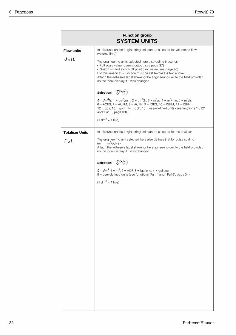
Function group
SYSTEM UNITS
Flow units
UnIt
In this function the engineering unit can be selected for volumetric flow(volume/time).
The engineering units selected here also define those for:• Full scale value (current output, see page 37)• Switch on and switch off point (limit value, see page 40)For this reason this function must be set before the two above.Attach the adhesive label showing the engineering unit to the field providedon the local display if it was changed!
Selection: 0
0 = dm3/s, 1 = dm3/min, 2 = dm3/h, 3 = m3/s, 4 = m3/min, 5 = m3/h, 6 = ACFS, 7 = ACFM, 8 = ACFH, 9 = IGPS, 10 = IGPM, 11 = IGPH,12 = gps, 13 = gpm, 14 = gph, 15 = user-defined units (see functions "Fu12"and "Fu13", page 33).
(1 dm3 = 1 litre)
Totaliser Units
Fui i
In this function the engineering unit can be selected for the totaliser.
The engineering unit selected here also defines that for pulse scaling(m3 → m3/pulse).Attach the adhesive label showing the engineering unit to the field providedon the local display if it was changed!
Selection: 0
0 = dm3, 1 = m3, 2 = ACF, 3 = Igallons, 4 = gallons,5 = user-defined units (see functions "Fu14" and " Fu15", page 34).
(1 dm3 = 1 litre)
6 Functions Prowirl 70
32 Endress+Hauser
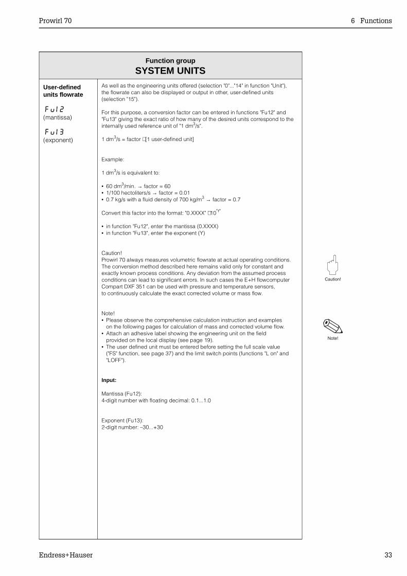
Function group
SYSTEM UNITS
User-definedunits flowrate
Fui2(mantissa)
Fui3(exponent)
As well as the engineering units offered (selection "0"..."14" in function "Unit"),the flowrate can also be displayed or output in other, user-defined units(selection "15").
For this purpose, a conversion factor can be entered in functions "Fu12" and"Fu13" giving the exact ratio of how many of the desired units correspond to theinternally used reference unit of "1 dm3/s".
1 dm3/s = factor ⋅ [1 user-defined unit]
Example:
1 dm3/s is equivalent to:
• 60 dm3/min. → factor = 60• 1/100 hectoliters/s → factor = 0.01• 0.7 kg/s with a fluid density of 700 kg/m3 → factor = 0.7
Convert this factor into the format: "0.XXXX" ⋅ 10"Y"
• in function "Fu12", enter the mantissa (0.XXXX)• in function "Fu13", enter the exponent (Y)
Caution!Prowirl 70 always measures volumetric flowrate at actual operating conditions.The conversion method described here remains valid only for constant andexactly known process conditions. Any deviation from the assumed processconditions can lead to significant errors. In such cases the E+H flowcomputerCompart DXF 351 can be used with pressure and temperature sensors,to continuously calculate the exact corrected volume or mass flow.
Note!• Please observe the comprehensive calculation instruction and examples
on the following pages for calculation of mass and corrected volume flow.• Attach an adhesive label showing the engineering unit on the field
provided on the local display (see page 19).• The user defined unit must be entered before setting the full scale value
("FS" function, see page 37) and the limit switch points (functions "L on" and"LOFF").
Input:
Mantissa (Fu12):4-digit number with floating decimal: 0.1...1.0
Exponent (Fu13):2-digit number: –30...+30
Prowirl 70 6 Functions
Endress+Hauser 33
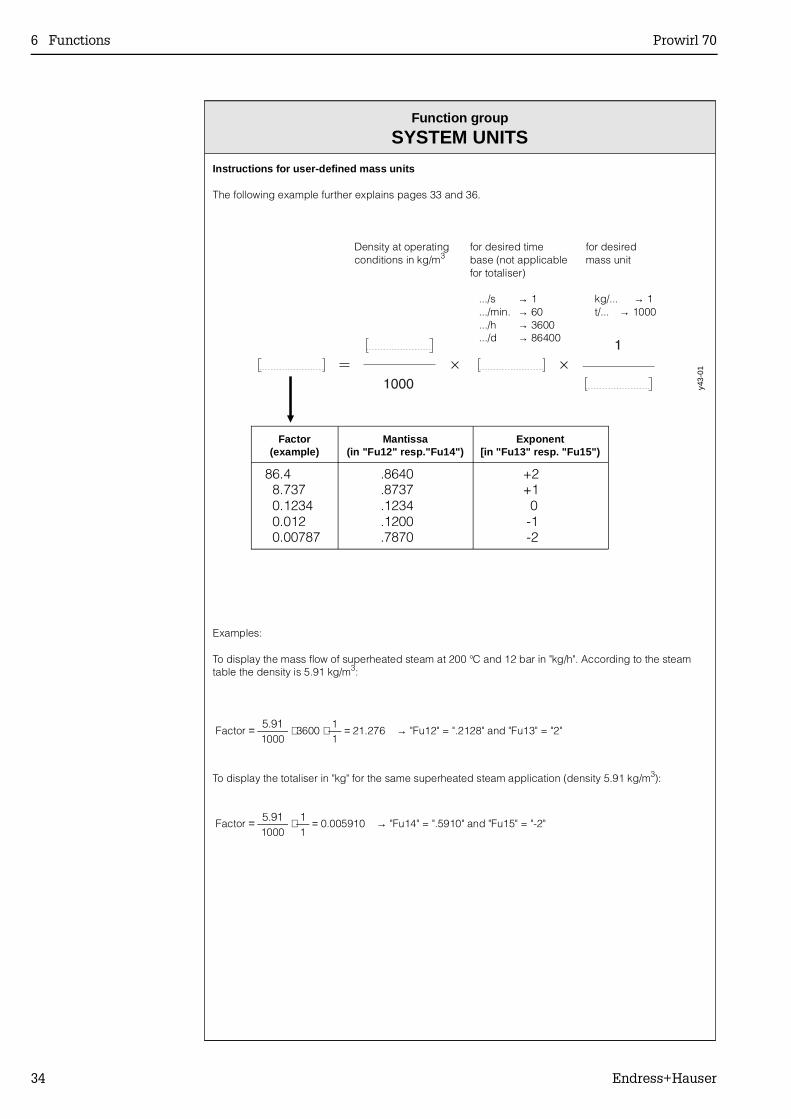
Function group
SYSTEM UNITS
Instructions for user-defined mass units
The following example further explains pages 33 and 36.
Examples:
To display the mass flow of superheated steam at 200 °C and 12 bar in "kg/h". According to the steamtable the density is 5.91 kg/m3:
Factor = 5.91
1000 ⋅ 3600 ⋅ 1
1 = 21.276 → "Fu12" = ".2128" and "Fu13" = "2"
To display the totaliser in "kg" for the same superheated steam application (density 5.91 kg/m3):
Factor = 5.91
1000 ⋅ 1
1 = 0.005910 → "Fu14" = ".5910" and "Fu15" = "-2"
Density at operatingconditions in kg/m3
for desired timebase (not applicablefor totaliser)
.../s → 1
.../min. → 60
.../h → 3600
.../d → 86400
for desiredmass unit
kg/... → 1t/... → 1000
y43-
01
Factor(example)
Mantissa(in "Fu12" resp."Fu14")
Exponent[in "Fu13" resp. "Fu15")
86.4 8.737 0.1234 0.012 0.00787
.8640
.8737
.1234
.1200
.7870
+2 +1 0 -1 -2
6 Functions Prowirl 70
34 Endress+Hauser
Function group
SYSTEM UNITS
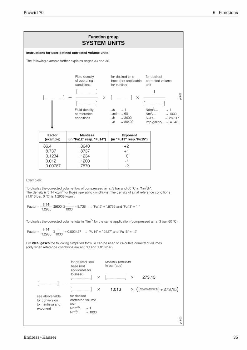
Instructions for user-defined corrected volume units
The following example further explains pages 33 and 36.
Examples:
To display the corrected volume flow of compressed air at 3 bar and 60 °C in "Nm3/h".The density is 3.14 kg/m3 for those operating conditions. The density of air at reference conditions(1.013 bar, 0 °C) is 1.2936 kg/m3:
Factor = 3.14
1.2936 ⋅ 3600 ⋅ 1
1000 = 8.738 → "Fu12" = ".8736 and "Fu13" = "1"
To display the corrected volume total in "Nm3" for the same application (compressed air at 3 bar, 60 °C):
Factor = 3.14
1.2936 ⋅ 1
1000 = 0.002427 → "Fu14" = ".2427" and "Fu15" = "-2"
For ideal gases the following simplified formula can be used to calculate corrected volumes(only when reference conditions are at 0 °C and 1.013 bar).
Fluid densityof operatingconditions
for desired timebase (not applicablefor totaliser)
for desiredcorrected volumeunit
Fluid densityat referenceconditions
.../s → 1
.../min. → 60
.../h → 3600
.../d → 86400
Ndm3/... → 1Nm3/... → 1000SCF/... → 28.317Imp.gallon/... → 4.546
y43-
02
Factor(example)
Mantissa(in "Fu12" resp. "Fu14")
Exponent[in "Fu13" resp."Fu15")
86.4 8.737 0.1234 0.012 0.00787
.8640
.8737
.1234
.1200
.7870
+2 +1 0 -1 -2
for desired timebase (notapplicable fortotaliser)
process pressure in bar (abs)
process temp.°C
for desiredcorrected volumeunitNdm3/... → 1Nm3/... → 1000
see above tablefor conversionto mantissa and exponent
y43-
03
Prowirl 70 6 Functions
Endress+Hauser 35
Function group
SYSTEM UNITS
User-definedunits totaliser
Fui4(mantissa)
Fui5(exponent)
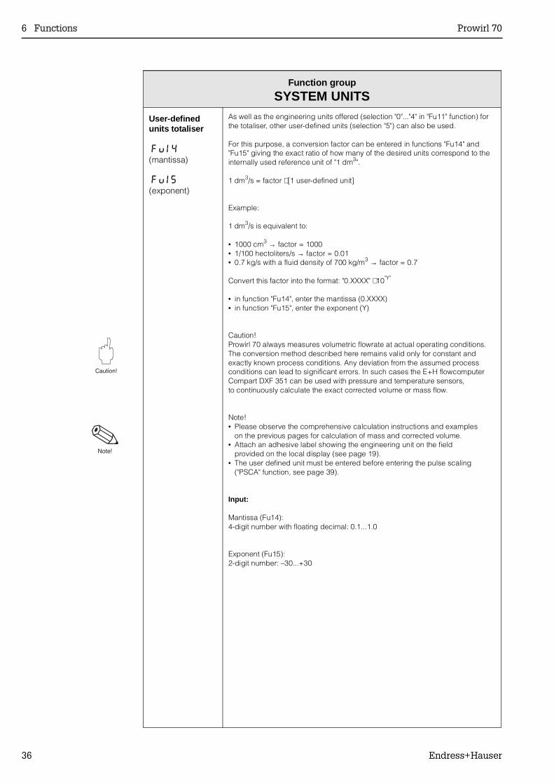
As well as the engineering units offered (selection "0"..."4" in "Fu11" function) forthe totaliser, other user-defined units (selection "5") can also be used.
For this purpose, a conversion factor can be entered in functions "Fu14" and"Fu15" giving the exact ratio of how many of the desired units correspond to theinternally used reference unit of "1 dm3".
1 dm3/s = factor ⋅ [1 user-defined unit]
Example:
1 dm3/s is equivalent to:
• 1000 cm3 → factor = 1000• 1/100 hectoliters/s → factor = 0.01• 0.7 kg/s with a fluid density of 700 kg/m3 → factor = 0.7
Convert this factor into the format: "0.XXXX" ⋅ 10"Y"
• in function "Fu14", enter the mantissa (0.XXXX)• in function "Fu15", enter the exponent (Y)
Caution!Prowirl 70 always measures volumetric flowrate at actual operating conditions.The conversion method described here remains valid only for constant andexactly known process conditions. Any deviation from the assumed processconditions can lead to significant errors. In such cases the E+H flowcomputerCompart DXF 351 can be used with pressure and temperature sensors,to continuously calculate the exact corrected volume or mass flow.
Note!• Please observe the comprehensive calculation instructions and examples
on the previous pages for calculation of mass and corrected volume.• Attach an adhesive label showing the engineering unit on the field
provided on the local display (see page 19).• The user defined unit must be entered before entering the pulse scaling
("PSCA" function, see page 39).
Input:
Mantissa (Fu14):4-digit number with floating decimal: 0.1...1.0
Exponent (Fu15):2-digit number: –30...+30
6 Functions Prowirl 70
36 Endress+Hauser
Function group
CURRENT OUTPUT
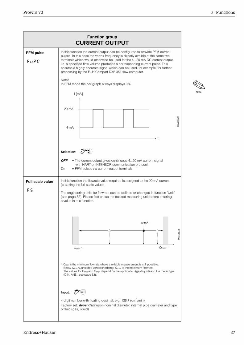
PFM pulse
Fu20
In this function the current output can be configured to provide PFM currentpulses. In this case the vortex frequency is directly avaible at the same twoterminals which would otherwise be used for the 4...20 mA DC current output,i.e. a specified flow volume produces a corresponding current pulse. Thisensures a highly accurate signal which can be used, for example, for furtherprocessing by the E+H Compart DXF 351 flow computer.
Note!In PFM mode the bar graph always displays 0%.
Selection: 0
OFF = The current output gives continuous 4...20 mA current signal with HART or INTENSOR communication protocol.
On = PFM pulses via current output terminals
Full scale value
FS
In this function the flowrate value required is assigned to the 20 mA current(= setting the full scale value).
The engineering units for flowrate can be defined or changed in function "UnIt"(see page 32). Please first chose the desired measuring unit before enteringa value in this function.
Input: 0
4-digit number with floating decimal, e.g. 126.7 (dm3/min)Factory set: dependent upon nominal diameter, internal pipe diameter and typeof fluid (gas, liquid)
l [mA]
20 mA
4 mA
t
ba01
8y39
Qmin * Qmax *
ba01
8y28
* Qmin is the minimum flowrate where a reliable measurement is still possible. Below Qmin unstable vortex shedding. Qmax is the maximum flowrate. The values for Qmin and Qmax depend on the application (gas/liquid) and the meter type (DIN, ANSI, see page 63).
Prowirl 70 6 Functions
Endress+Hauser 37
Function group
CURRENT OUTPUT
Time constant
Fu22
Selecting the time constant determines how quickly the current output signaland the display respond to rapidly fluctuating flowrates (small time constant) orare delayed (large time constant).
Note!The time constant defines the lower limit of the response time of the currentoutput. If the vortex period is larger than the selected time constant, then this isincreased automatically.
Input: 0
3-digit number with fixed decimal: 0.2...100.0 (seconds)Factory set: 5.0 (seconds)
Failsafe mode
Fu23
In cases of fault it is advisable for safety reasons that the current outputassumes a previously defined status which can be set in this function.
This function is only available if the setting "OFF" is selected in function "Fu20"(see page 37).
Selection: 0
Lo = minimum current value (the current signal is set to ≤3.6 mA on error)HI = maximum current value (the current signal is set to ≥21 mA on error)run = normal measured value given despite error
Simulation
Fu24
In this function the output current can be simulated to correspond to 0%, 50% or100% of the current range (4, 12, 20 mA) to check wiring or connectedinstruments.This function is only available if the setting "OFF" is selected in function "Fu20" (see page 37).
Note!• The simulation mode affects only the current output.
During simulation the flowmeter remains fully operational for measurement,i.e. totaliser, flow display and pulse output are operating normally.
• If OFF is not selected, in HOME position the bar graph shows the selected output current simulation value in % and not the actual flowrate in %.
Selection: 0
OFF (current output follows actual measured value) –4 (mA) – 12 (mA) – 20 (mA)
Nominal current
Fu25
In this function is shown the actual value of the output current.
This function is only available if the setting "OFF" is selected in function "Fu20"(see page 37).
Display:
Actual value: 4.00...20.50 (mA)(or 3.6 resp. 22 mA as fault indication; see function "Fu23")
6 Functions Prowirl 70
38 Endress+Hauser

Function group
OPEN COLLECTOR OUTPUTNote!With the Ex d (explosion proof) version, the complete OPEN COLLECTOR OUTPUT function groupis not available.
Open Collectorfunctions
OCFU
Various functions can be assigned to the open collector output. This outputoperates independently of the current output.
Selection: 0
Pout = Pulse output: An output pulse is produced for a freely selectableflowrate (see also function "PSCA").
AOn = Fault output: active ’on’. In cases of error, e.g. with defective sensor,the open collector is conducting.
AOFF = Fault output: active ’off’. In cases of error, e.g. with defective sensor,the open collector is not conducting.
L = The output is configured as a ’limit switch’.The appropriate switch on and switch off points can be set in functions"L on" and "LOFF" (see page 40).
Pulse scaling
PSCA
In this function the freely selectable flow quantity is determined which an outputpulse represents.
This function is only available if the setting "Pout" is selected in function"OCFU".The engineering units for pulse scaling can be defined or changed in function"Fu11" (see page 32).Ensure that the pulse scaling is chosen so that the pulse frequencyfor minimum/maximum flow falls within the range of 0.000007...100 Hz.Frequencies of 1 Hz and higher are output with 50/50 duty cycle, lowerfrequencies are output with a fixed pulse width of 0.5 seconds.
Input: 0
4-digit number with floating decimal, e.g. 1.000 (m3/pulse)Factory set: dependent upon nominal diameter and type of fluid (gas, liquid)
Simulation(pulse output)
Fu32
With this function predefined frequency signals can be simulated, for example,to check instruments connected.This function is only available if the setting "Pout" is selected in the function "OCFU".
Note!During simulation the flowmeter remains fully operational for measurement,i.e. totaliser, flow display and current output are operating normally.
Selection: 0
OFF – 1 (Hz) – 50 (Hz) – 100 (Hz)
Prowirl 70 6 Functions
Endress+Hauser 39
Function group
OPEN COLLECTOR OUTPUT
Nominalfrequency
Fu33
In this function is shown the actual value of the pulse output which is calculatedfrom the pulse scaling.
This function is only available if the setting "Pout" is selected in function "OCFU".
Display:
4-digit number with floating decimal: 0.0000...100.0 (Hz)
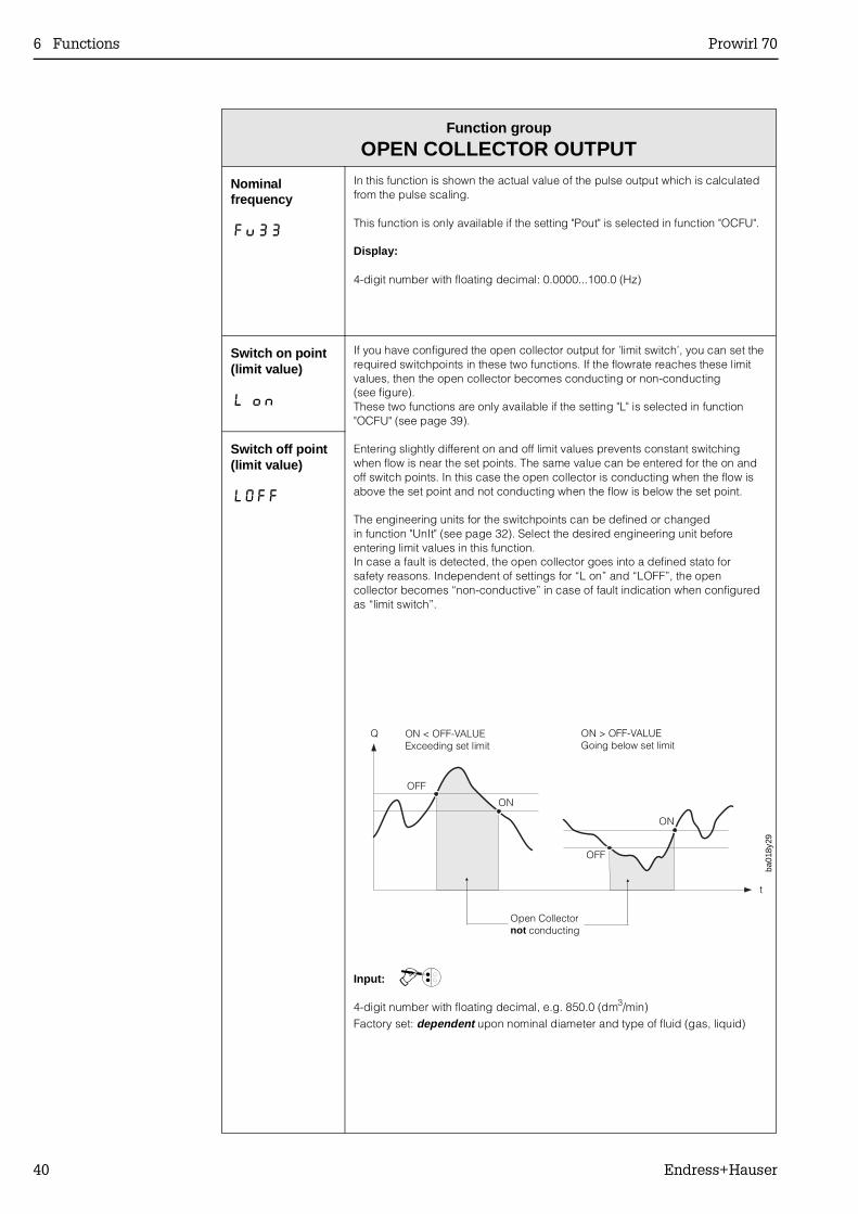
Switch on point(limit value)
L on
If you have configured the open collector output for ’limit switch’, you can set therequired switchpoints in these two functions. If the flowrate reaches these limitvalues, then the open collector becomes conducting or non-conducting(see figure).These two functions are only available if the setting "L" is selected in function"OCFU" (see page 39).
Entering slightly different on and off limit values prevents constant switchingwhen flow is near the set points. The same value can be entered for the on andoff switch points. In this case the open collector is conducting when the flow isabove the set point and not conducting when the flow is below the set point.
The engineering units for the switchpoints can be defined or changedin function "UnIt" (see page 32). Select the desired engineering unit beforeentering limit values in this function.In case a fault is detected, the open collector goes into a defined stato forsafety reasons. Independent of settings for “L on” and “LOFF”, the opencollector becomes “non-conductive” in case of fault indication when configuredas “limit switch”.
Input: 0
4-digit number with floating decimal, e.g. 850.0 (dm3/min)Factory set: dependent upon nominal diameter and type of fluid (gas, liquid)
Switch off point(limit value)
LOFF
OFF
OFF
Q
Open Collectornot conducting
ba01
8y29
t
ON > OFF-VALUEGoing below set limit
ON < OFF-VALUEExceeding set limit
ON
ON
6 Functions Prowirl 70
40 Endress+Hauser
Function group
DISPLAY
Display mode
dISP
In this function the variable is defined which should be displayed during normaloperation ("HOME position" = standard display).
Attach the adhesive label showing the engineering unit on the field provided onthe local display, in case you change the factory setting.
Selection: 0
Proc = Display flowrate in %rAtE = Display flowrate (vol/time, see also page 32)Ltot = Display totaliser (see also page 31)Htot = Display the number of totaliser overruns (see also page 31)
Note!For setting "Proc", the value shown on the display refers to the full scale valueset in function "FS" (see page 37).
Totaliser reset
Fu4 i
In this function the totaliser (incl. overruns) can be set to ’zero’ (reset).
Selection: 0
ESC = Totaliser will not be resetrESE= Totaliser is reset to zero
Prowirl 70 6 Functions
Endress+Hauser 41
Function group
SYSTEM PARAMETERS
Private code(definition)
Fu50
In this function a personal code number can be defined with whichprogramming can be enabled.
The code number can only be altered when programming has been enabled.When programming is locked this function is not available and access to thepersonal code number by third parties is not possible.Programming is always enabled with code number "0".
Input: 0
max. 4-digit number: 0...9999Factory set: 70
Access code
CodE
All data of the Prowirl measuring system are protected against unauthorisedchanges. Only by first entering a code number in this function is programmingenabled and the settings of the instrument can then be altered.If in any function the pushbuttons + / – are pressed, then the measuring systemjumps automatically into this function and the display shows the Code promptto enter the code number (if programming is locked):→ Enter code number 70 (factory set) or→ Enter previously defined personal code number (see function "Fu50")
Lock programming: After jumping to the HOME position, programmingis locked again after 60 seconds if no pushbutton is pressed during this time.Programming can also be locked by entering any number (not the code number) in this function.If you can no longer find your personal code number, then theEndress+Hauser Service Organisation will be pleased to help you.
Input: 0
max. 4-digit number: 0...9999Factory set: 0
6 Functions Prowirl 70
42 Endress+Hauser
Function group
SYSTEM PARAMETERS
Meter status StAt
In this function all present error messages can be called up.Errors which occur during operation are shown by a flashing display.The Prowirl measuring system differentiates between two types of errormessages:
System error message:An error code flashes on the display (HOME position).These errors directly affect the measurement → Correct the errorimmediately (see below).Error response of the current output: see function “Fu23”, page 38.Error response of the pulse output: the signal is set to the fall-backvalue = 0 Hz.
Warning message:The actual measured value flashes on the display (HOME position).The bargraph also flashes if the measuring range is exceeded.These errors do not affect the measurement → The measuring systemcontinues to measure but these “non-critical” errors are to be corrected assoon as possible.
Note!• This function is only viewable when an error/warning message exists.• When a number of errors have occurred, the one with the highest priority
is shown.• No system or warning messages are shown while in programming
mode (except in functions “Fu00”, “Fu01”, “Fu02”, “Fu03”, “Fu25" and“Fu33”).
• Once the error has been corrected, the normal measured value is againshown on the display resp. the bargraph stops flashing.
Display and remedial action
System error messages:E101 = Sensor is defective → To be corrected by E+H ServiceE102 = Internal EEPROM error (check sum error) → To be corrected by
E+H ServiceE103 = Communications error with sensor → Measuring system should be
restarted (switch off power supply and then switch on again);otherwise to be corrected by E+H Service.
Warning messages:E201 = DAT error (no access to DAT possible, DAT not plugged in) →
To be corrected by E+H ServiceE202 = DAT error (check sum error) → To be corrected by E+H ServiceE203 = The measuring range of the current output is exceeded → Check
application, decrease flowrate or extend full scale value.E204 = The measuring range of the pulse output is exceeded → Check
application, decrease flowrate or adjust pulse scaling.
Prowirl 70 6 Functions
Endress+Hauser 43
Function group
SYSTEM PARAMETERS
Software versionmain board
Fu53
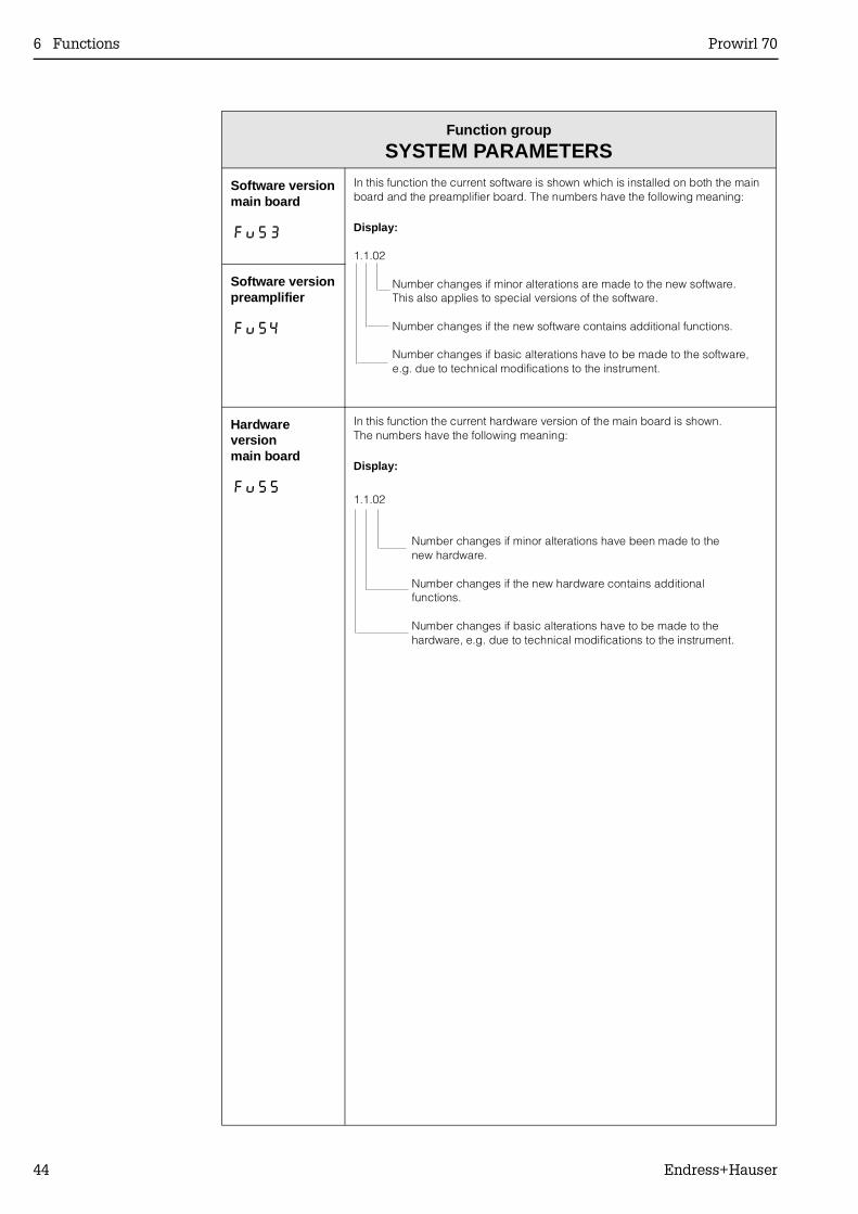
In this function the current software is shown which is installed on both the mainboard and the preamplifier board. The numbers have the following meaning:
Display:
1.1.02
Number changes if minor alterations are made to the new software. This also applies to special versions of the software.
Number changes if the new software contains additional functions.
Number changes if basic alterations have to be made to the software,e.g. due to technical modifications to the instrument.
Software versionpreamplifier
Fu54
Hardwareversionmain board
Fu55
In this function the current hardware version of the main board is shown.The numbers have the following meaning:
Display:
1.1.02
Number changes if minor alterations have been made to thenew hardware.
Number changes if the new hardware contains additionalfunctions.
Number changes if basic alterations have to be made to thehardware, e.g. due to technical modifications to the instrument.
6 Functions Prowirl 70
44 Endress+Hauser
Function group
MEASURING SYSTEM DATA
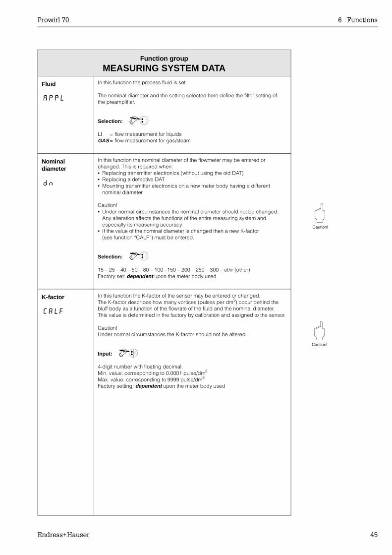
Fluid
APPL
In this function the process fluid is set.
The nominal diameter and the setting selected here define the filter setting ofthe preamplifier.
Selection: 0
LI = flow measurement for liquidsGAS = flow measurement for gas/steam
Nominaldiameter
dn
In this function the nominal diameter of the flowmeter may be entered orchanged. This is required when:• Replacing transmitter electronics (without using the old DAT)• Replacing a defective DAT• Mounting transmitter electronics on a new meter body having a different
nominal diameter.
Caution!• Under normal circumstances the nominal diameter should not be changed.
Any alteration affects the functions of the entire measuring system andespecially its measuring accuracy.
• If the value of the nominal diameter is changed then a new K-factor(see function “CALF”) must be entered.
Selection: 0
15 – 25 – 40 – 50 – 80 – 100 –150 – 200 – 250 – 300 – othr (other)Factory set: dependent upon the meter body used
K-factor
CALF
In this function the K-factor of the sensor may be entered or changed.The K-factor describes how many vortices (pulses per dm3) occur behind thebluff body as a function of the flowrate of the fluid and the nominal diameter.This value is determined in the factory by calibration and assigned to the sensor.
Caution!Under normal circumstances the K-factor should not be altered.
Input: 0
4-digit number with floating decimal,Min. value: corresponding to 0.0001 pulse/dm3
Max. value: corresponding to 9999 pulse/dm3
Factory setting: dependent upon the meter body used
Prowirl 70 6 Functions
Endress+Hauser 45
Function group
MEASURING SYSTEM DATA
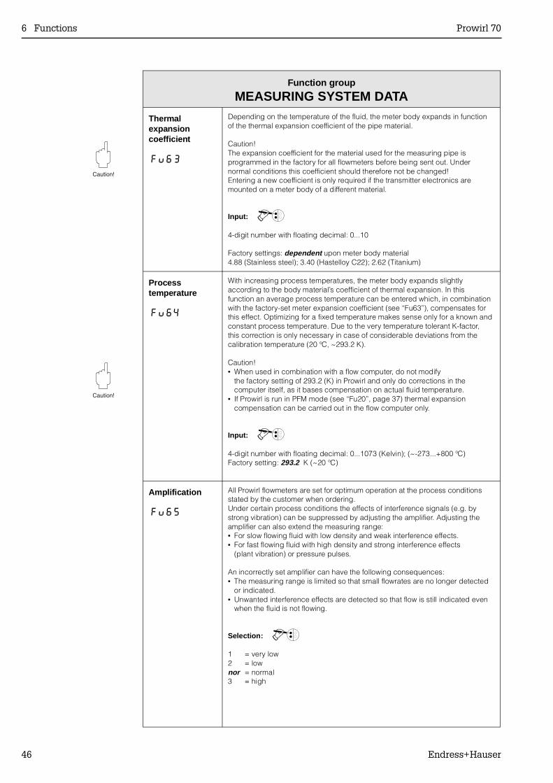
Thermalexpansioncoefficient
Fu63
Depending on the temperature of the fluid, the meter body expands in functionof the thermal expansion coefficient of the pipe material. Caution!The expansion coefficient for the material used for the measuring pipe isprogrammed in the factory for all flowmeters before being sent out. Undernormal conditions this coefficient should therefore not be changed!Entering a new coefficient is only required if the transmitter electronics aremounted on a meter body of a different material.
Input: 0
4-digit number with floating decimal: 0...10
Factory settings: dependent upon meter body material4.88 (Stainless steel); 3.40 (Hastelloy C22); 2.62 (Titanium)
Processtemperature
Fu64
With increasing process temperatures, the meter body expands slightlyaccording to the body material’s coefficient of thermal expansion. In thisfunction an average process temperature can be entered which, in combinationwith the factory-set meter expansion coefficient (see “Fu63”), compensates forthis effect. Optimizing for a fixed temperature makes sense only for a known andconstant process temperature. Due to the very temperature tolerant K-factor,this correction is only necessary in case of considerable deviations from thecalibration temperature (20 °C, ~293.2 K).
Caution!• When used in combination with a flow computer, do not modify
the factory setting of 293.2 (K) in Prowirl and only do corrections in thecomputer itself, as it bases compensation on actual fluid temperature.
• If Prowirl is run in PFM mode (see “Fu20”, page 37) thermal expansioncompensation can be carried out in the flow computer only.
Input: 0
4-digit number with floating decimal: 0...1073 (Kelvin); (~-273...+800 °C)Factory setting: 293.2 K (~20 °C)
Amplification
Fu65
All Prowirl flowmeters are set for optimum operation at the process conditionsstated by the customer when ordering.Under certain process conditions the effects of interference signals (e.g. bystrong vibration) can be suppressed by adjusting the amplifier. Adjusting theamplifier can also extend the measuring range:• For slow flowing fluid with low density and weak interference effects.• For fast flowing fluid with high density and strong interference effects
(plant vibration) or pressure pulses.
An incorrectly set amplifier can have the following consequences:• The measuring range is limited so that small flowrates are no longer detected
or indicated.• Unwanted interference effects are detected so that flow is still indicated even
when the fluid is not flowing.
Selection: 0
1 = very low2 = lownor = normal3 = high
6 Functions Prowirl 70
46 Endress+Hauser
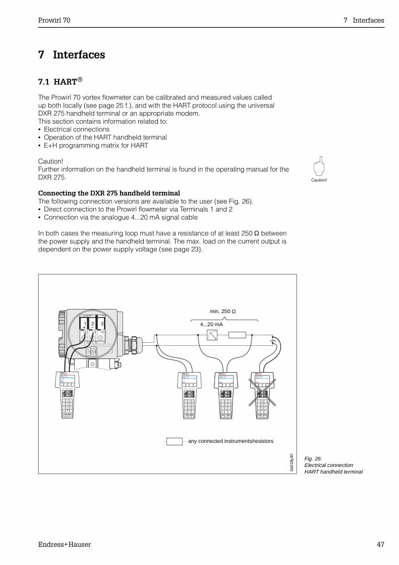
7 Interfaces
7.1 HART®
The Prowirl 70 vortex flowmeter can be calibrated and measured values calledup both locally (see page 25 f.), and with the HART protocol using the universalDXR 275 handheld terminal or an appropriate modem.This section contains information related to:• Electrical connections• Operation of the HART handheld terminal• E+H programming matrix for HART
Caution!Further information on the handheld terminal is found in the operating manual for theDXR 275.
Connecting the DXR 275 handheld terminalThe following connection versions are available to the user (see Fig. 26).• Direct connection to the Prowirl flowmeter via Terminals 1 and 2• Connection via the analogue 4...20 mA signal cable
In both cases the measuring loop must have a resistance of at least 250 Ω betweenthe power supply and the handheld terminal. The max. load on the current output isdependent on the power supply voltage (see page 23).
ba01
8y40
min. 250 Ω
4...20 mA
any connected instruments/resistors
Fig. 26:Electrical connectionHART handheld terminal
Prowirl 70 7 Interfaces
Endress+Hauser 47
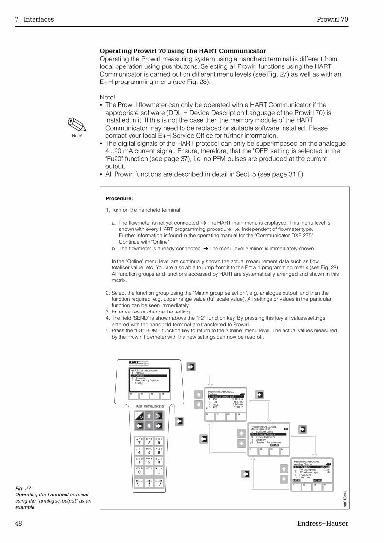
Operating Prowirl 70 using the HART CommunicatorOperating the Prowirl measuring system using a handheld terminal is different fromlocal operation using pushbuttons. Selecting all Prowirl functions using the HARTCommunicator is carried out on different menu levels (see Fig. 27) as well as with anE+H programming menu (see Fig. 28).
Note!• The Prowirl flowmeter can only be operated with a HART Communicator if the
appropriate software (DDL = Device Description Language of the Prowirl 70) isinstalled in it. If this is not the case then the memory module of the HARTCommunicator may need to be replaced or suitable software installed. Pleasecontact your local E+H Service Office for further information.
• The digital signals of the HART protocol can only be superimposed on the analogue4...20 mA current signal. Ensure, therefore, that the "OFF" setting is selected in the"Fu20" function (see page 37), i.e. no PFM pulses are produced at the currentoutput.
• All Prowirl functions are described in detail in Sect. 5 (see page 31 f.)
ba01
8e41
HART Communicator 1 Offline
3 Transfer4 Frequency Device5 Utility
2->Online
Prowirl70: ABC0001Online1->Matrix group sel.2 PV3 Tot4 AO15 FO
33.00 L/s456.4 L
6.30 mA2.00 Hz
Prowirl70: ABC0001Analog Output
2 PV Damping3 AO Alarm type4 Loop test5 D/A trim
1->PV URV
Prowirl70: ABC0001Matrix group sel.1 System Units
3 Open Collector4 Display5 System Parameters
2 ->Analog Output
100 L/s0.2 s
Hi
HOME
HOMEHELP
IO
Procedure:
1. Turn on the handheld terminal:
a. The flowmeter is not yet connected The HART main menu is displayed. This menu level is shown with every HART programming procedure, i.e. independent of flowmeter type. Further information is found in the operating manual for the "Communicator DXR 275". Continue with "Online"
b. The flowmeter is already connected The menu level "Online" is immediately shown.
In the "Online" menu level are continually shown the actual measurement data such as flow,totaliser value, etc. You are also able to jump from it to the Prowirl programming matrix (see Fig. 28).All function groups and functions accessed by HART are systematically arranged and shown in thismatrix.
2. Select the function group using the "Matrix group selection", e.g. analogue output, and then thefunction required, e.g. upper range value (full scale value). All settings or values in the particularfunction can be seen immediately.
3. Enter values or change the setting.4. The field "SEND" is shown above the “F2” function key. By pressing this key all values/settings
entered with the handheld terminal are transferred to Prowirl.5. Press the “F3” HOME function key to return to the "Online" menu level. The actual values measured
by the Prowirl flowmeter with the new settings can now be read off.
Fig. 27:Operating the handheld terminalusing the “analogue output” as anexample
7 Interfaces Prowirl 70
48 Endress+Hauser
ba01
8e42
All
setti
ngs
can
be c
alle
d up
one
afte
r th
e ot
her
in th
is fu
nctio
n gr
oup
(with
HA
RT
onl
y)
The
se fu
nctio
ns a
re d
ispl
ayed
onl
y w
ith th
e co
rres
pond
ing
conf
igur
atio
n in
oth
er fu
nctio
ns
Fun
ctio
n de
scrip
tion
(The
Pro
wirl
func
tion
nam
es o
n th
e H
AR
T h
andh
eld
term
inal
may
diff
er s
light
ly fr
om th
e fu
nctio
n na
mes
giv
en in
Sec
tion
6).
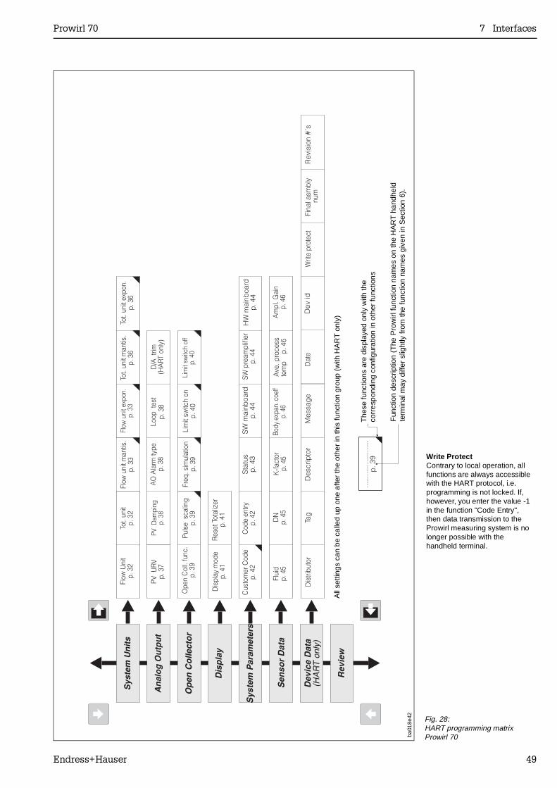
Fig. 28:HART programming matrix Prowirl 70
Write ProtectContrary to local operation, allfunctions are always accessiblewith the HART protocol, i.e.programming is not locked. If,however, you enter the value -1in the function "Code Entry",then data transmission to theProwirl measuring system is nolonger possible with thehandheld terminal.
Prowirl 70 7 Interfaces
Endress+Hauser 49
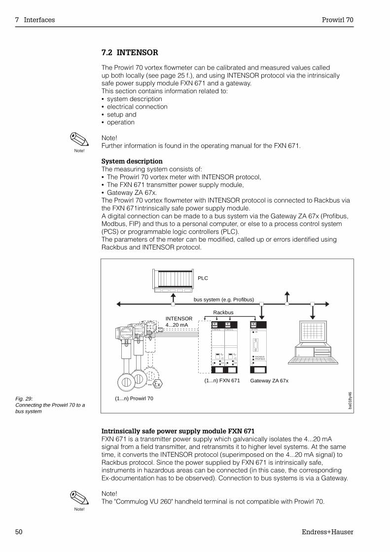
7.2 INTENSOR
The Prowirl 70 vortex flowmeter can be calibrated and measured values calledup both locally (see page 25 f.), and using INTENSOR protocol via the intrinsicallysafe power supply module FXN 671 and a gateway.This section contains information related to:• system description• electrical connection• setup and• operation
Note!Further information is found in the operating manual for the FXN 671.
System descriptionThe measuring system consists of:• The Prowirl 70 vortex meter with INTENSOR protocol,• The FXN 671 transmitter power supply module,• Gateway ZA 67x.The Prowirl 70 vortex flowmeter with INTENSOR protocol is connected to Rackbus viathe FXN 671intrinsically safe power supply module.A digital connection can be made to a bus system via the Gateway ZA 67x (Profibus,Modbus, FIP) and thus to a personal computer, or else to a process control system(PCS) or programmable logic controllers (PLC).The parameters of the meter can be modified, called up or errors identified usingRackbus and INTENSOR protocol.
Intrinsically safe power supply module FXN 671FXN 671 is a transmitter power supply which galvanically isolates the 4...20 mA signal from a field transmitter, and retransmits it to higher level systems. At the sametime, it converts the INTENSOR protocol (superimposed on the 4...20 mA signal) toRackbus protocol. Since the power supplied by FXN 671 is intrinsically safe,instruments in hazardous areas can be connected (in this case, the correspondingEx-documentation has to be observed). Connection to bus systems is via a Gateway.
Note!The "Commulog VU 260" handheld terminal is not compatible with Prowirl 70.
ZA 673ON
RACKBUSPROFIBUS
FXN 671FXN 671
+mA-
+mA-
ba01
8y46
PLC
bus system (e.g. Profibus)
RackbusINTENSOR4...20 mA
(1...n) Prowirl 70
Gateway ZA 67x(1...n) FXN 671
Fig. 29:Connecting the Prowirl 70 to a bus system
7 Interfaces Prowirl 70
50 Endress+Hauser
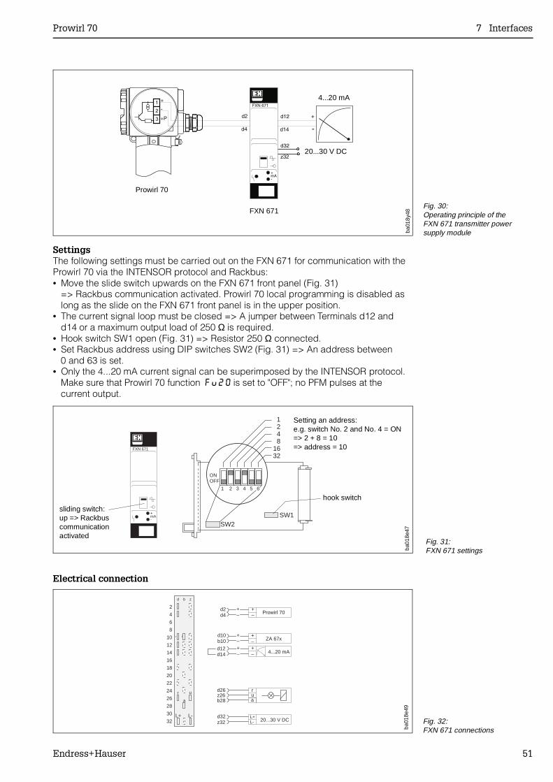
SettingsThe following settings must be carried out on the FXN 671 for communication with theProwirl 70 via the INTENSOR protocol and Rackbus:• Move the slide switch upwards on the FXN 671 front panel (Fig. 31)
=> Rackbus communication activated. Prowirl 70 local programming is disabled aslong as the slide on the FXN 671 front panel is in the upper position.
• The current signal loop must be closed => A jumper between Terminals d12 andd14 or a maximum output load of 250 Ω is required.
• Hook switch SW1 open (Fig. 31) => Resistor 250 Ω connected.• Set Rackbus address using DIP switches SW2 (Fig. 31) => An address between
0 and 63 is set.• Only the 4...20 mA current signal can be superimposed by the INTENSOR protocol.
Make sure that Prowirl 70 function Fu20 is set to "OFF"; no PFM pulses at thecurrent output.
Electrical connection
ba01
8y48
4...20 mA
20...30 V DC
Prowirl 70
FXN 671Fig. 30:Operating principle of the FXN 671 transmitter power supply module
ONOFF
SW2SW1
1 2 3 4 5 6
1248
1632
FXN 671
+mA-
ba01
8e47
Setting an address:e.g. switch No. 2 and No. 4 = ON=> 2 + 8 = 10=> address = 10
sliding switch:up => Rackbuscommunicationactivated
hook switch
Fig. 31:FXN 671 settings
d b z
L+ L-
+
2
4
6
8
10
12
14
16
18
20
22
24
26
28
30
32
r
a
u rua
d26z26b28
d2d4 Prowirl 70
+–
+–
+–+–
d10b10
d12d14
+–+–
ZA 67x
4...20 mA
d32z32
L+L- 20...30 V DC
ba01
8e49
Fig. 32:FXN 671 connections
Prowirl 70 7 Interfaces
Endress+Hauser 51
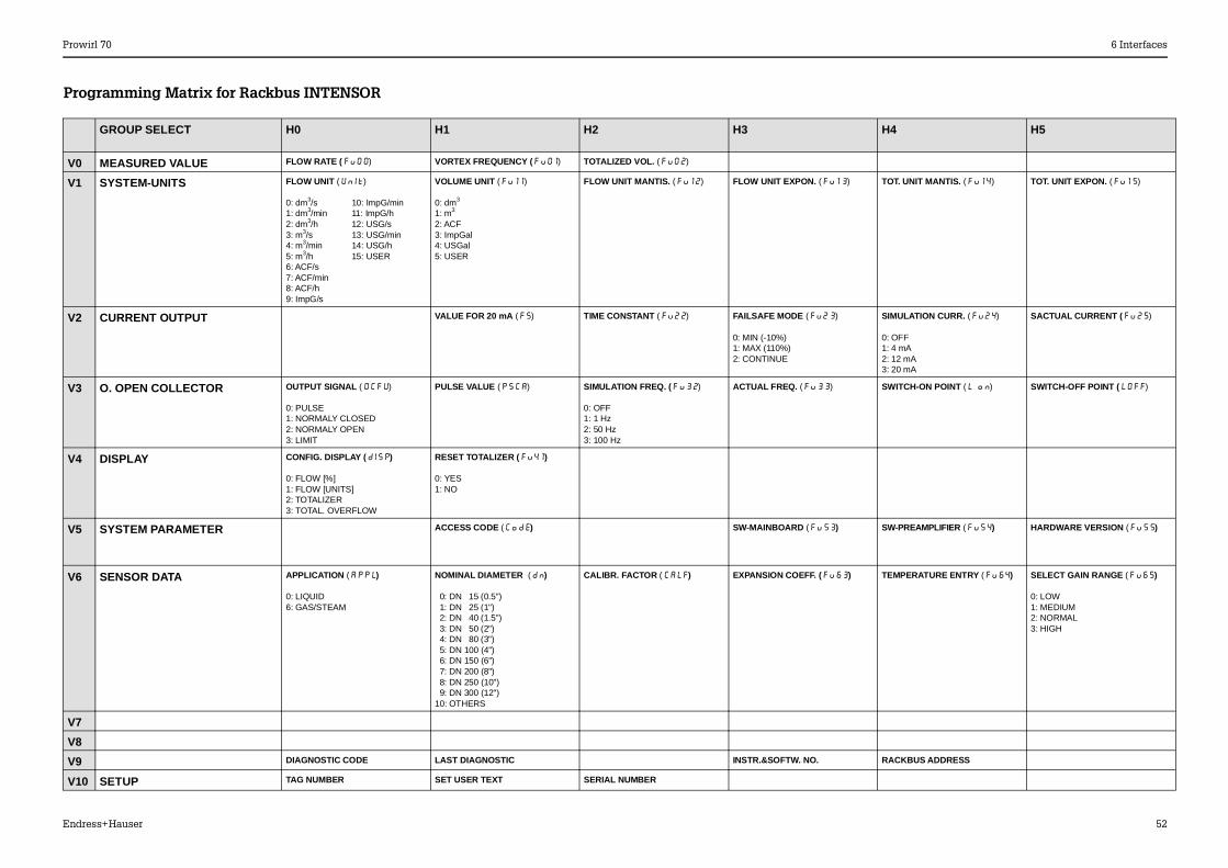
GROUP SELECT H0 H1 H2 H3 H4 H5
V0 MEASURED VALUE FLOW RATE (Fu00) VORTEX FREQUENCY (Fu01) TOTALIZED VOL. (Fu02)
V1 SYSTEM-UNITS FLOW UNIT (Unit)
0: dm3/s 10: ImpG/min1: dm3/min 11: ImpG/h2: dm3/h 12: USG/s3: m3/s 13: USG/min4: m3/min 14: USG/h5: m3/h 15: USER 6: ACF/s7: ACF/min8: ACF/h9: ImpG/s
VOLUME UNIT (Fu11)
0: dm3
1: m3
2: ACF3: ImpGal4: USGal5: USER
FLOW UNIT MANTIS. (Fu12) FLOW UNIT EXPON. (Fu13) TOT. UNIT MANTIS. (Fu14) TOT. UNIT EXPON. (Fu15)
V2 CURRENT OUTPUT VALUE FOR 20 mA (FS) TIME CONSTANT (Fu22) FAILSAFE MODE (Fu23)
0: MIN (-10%)1: MAX (110%)2: CONTINUE
SIMULATION CURR. (Fu24)
0: OFF1: 4 mA2: 12 mA3: 20 mA
SACTUAL CURRENT (Fu25)
V3 O. OPEN COLLECTOR OUTPUT SIGNAL (OCFU)
0: PULSE1: NORMALY CLOSED2: NORMALY OPEN3: LIMIT
PULSE VALUE (PSCA) SIMULATION FREQ. (Fu32)
0: OFF1: 1 Hz2: 50 Hz3: 100 Hz
ACTUAL FREQ. (Fu33) SWITCH-ON POINT (L on) SWITCH-OFF POINT (LOff)
V4 DISPLAY CONFIG. DISPLAY (dISP)
0: FLOW [%]1: FLOW [UNITS]2: TOTALIZER3: TOTAL. OVERFLOW
RESET TOTALIZER (Fu41)
0: YES1: NO
V5 SYSTEM PARAMETER ACCESS CODE (Code) SW-MAINBOARD (Fu53) SW-PREAMPLIFIER (Fu54) HARDWARE VERSION (Fu55)
V6 SENSOR DATA APPLICATION (APPL)
0: LIQUID6: GAS/STEAM
NOMINAL DIAMETER (dn)
0: DN 15 (0.5") 1: DN 25 (1") 2: DN 40 (1.5") 3: DN 50 (2") 4: DN 80 (3") 5: DN 100 (4") 6: DN 150 (6") 7: DN 200 (8") 8: DN 250 (10") 9: DN 300 (12")10: OTHERS
CALIBR. FACTOR (CALF) EXPANSION COEFF. (Fu63) TEMPERATURE ENTRY (Fu64) SELECT GAIN RANGE (Fu65)
0: LOW1: MEDIUM2: NORMAL3: HIGH
V7
V8
V9 DIAGNOSTIC CODE LAST DIAGNOSTIC INSTR.&SOFTW. NO. RACKBUS ADDRESS
V10 SETUP TAG NUMBER SET USER TEXT SERIAL NUMBER
Programming Matrix for Rackbus INTENSOR
Prowirl 70 6 Interfaces
Endress+Hauser 52
8 Troubleshooting
8.1 System Fault Indication
The response of the measuring system on fault is described in detail on page 43(→ function "StAt").
8.2 Error Check List and Correcting Faults
During the production process all instruments are subject to various stages of qualityassurance. The last of these controls is wet calibration which is carried out onstate-of-the-art calibration rigs. If faults should occur after start-up or duringoperation, then the following points should be checked using the check list givenbelow:
Electrical Connections• Is there a power supply at the connection terminals (→ page 21)?• Check the wiring according to the diagrams (→ page 21, 22 ).• Check the load resistors and wiring polarity (→ page 23)
Mounting and Installation• Have all mounting regulations been followed when installing in the pipeline?• Have both protective disks been removed from the sensor before mounting
(→ page 16)?• Measuring liquids: Is the pipeline completely filled (→ page 12)?• The fluid must be single phased!• Is the back pressure sufficiently high to prevent cavitation (→ page 12)?• Are the internal diameters of the measuring pipe and the piping identical
(→ page 13)?• Do the inlet and outlet fulfil the following requirements (→ page 13)?
Circular cross section?Visual check for straightness?Smooth with no junctions, fittings, dents or build-up?No parts (e.g. gaskets) protruding into the piping?
• Are sensor and transmitter isolated from vibration?With very strong and continuous vibration of the piping (>1 g, dependent onfrequency, amplitude and direction), a flowrate can still be shown under certainconditions with no flow.Remedies → Identify the source of the vibration. This is usually in the vicinity of themeasuring point. Using the program function "Amplification" (→ page 46),you can eliminate the effects of interference signals which are generated by verystrong vibrations.
Process data• Does the actual flowrate lie within the measuring range of the flowmeter (see table
on page 63)? If this is not the case → Check the application and reduce the flow orreadjust the full scale value (→ page 37) or pulse scaling (→ page 39).
• Do the process data* such as temperature, pressure, viscosity and density of thefluid agree with the specifications at the time of ordering? If this is not the case → Recheck all program data and inform your E+H Service Office.(* These data should be known so that the initial value and linearity range can bechecked).
• If pressure pulses (e.g. caused by reciprocating pumps) are superimposed on theoperating pressure and have similar frequencies as the vortex shedding frequency,then differences between vortex and pulsation can only be detected under certainconditions using this measuring principle (→ page 12).
Prowirl 70 8 Troubleshooting
Endress+Hauser 53
8.3 Repairs and Dangerous Chemicals
All instruments sent to Endress+Hauser for repair must always be accompanied by anote containing the following information:• Description of the application• Description of the error• Chemical and physical properties of the product being measured
Caution!The following procedures must be carried out before a Prowirl 70flowmeter is sent to Endress+Hauser for repair:• Remove all residue which may be present. Pay special attention to the gasket
grooves and crevices where fluid may be present.This is especially important if the fluid is dangerous to health, e.g. corrosive,poisonous, carcinogenic, radioactive, etc.
• No instrument should be returned to us without first completely removing alldangerous material (e.g. in scratches or diffused though plastic).
Incomplete cleaning of the instrument may result in cost for waste disposal or causeharm to personnel (burns, etc.). Any costs arising from this will be charged to theowner of the instrument.
8.4 Maintenance
No maintenance is required once the flowmeter has been correctly installed.
8 Troubleshooting Prowirl 70
54 Endress+Hauser
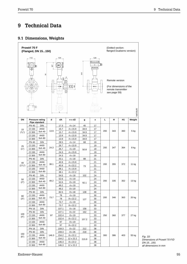
9 Technical Data
9.1 Dimensions, Weights
Prowirl 70 F(Flanged, DN 15...150)
(Dotted section:flanged Dualsens version)
DN Pressure ratingPipe standard
d dA n x d2 g x L H H1 Weight
15(1⁄2")
PN 40 DIN
13.9
17.3 4 x 14 45 17
200 343 360 5 kgCl 150 ANSI
Sch 4015.7 4 x 15.9 34.9 17
Cl 300 15.7 4 x 15.9 34.9 17
Cl 150 ANSISch 80
13.9 4 x 15.9 34.9 17
Cl 300 13.9 4 x 15.9 34.9 17
25(1")
PN 40 DIN
24.3
28.5 4 x 14 68 19
200 347 364 8 kgCl 150 ANSI
Sch 4026.7 4 x 15.9
50.8
19
Cl 300 26.7 4 x 19 19
Cl 150 ANSISch 80
24.3 4 x 15.9 19
Cl 300 24.3 4 x 19 19
40(11⁄2")
PN 40 DIN
38.1
43.1 4 x 18 88 21
200 355 372 11 kgCl 150 ANSI
Sch 4040.9 4 x 15.9
73
21
Cl 300 40.9 4 x 22.2 21
Cl 150 ANSISch 80
38.1 4 x 15.9 21
Cl 300 38.1 4 x 22.2 21
50(2")
PN 40 DIN
49.2
54.5 4 x 18 102 24
200 335 352 13 kgCl 150 ANSI
Sch 4052.6 4 x 19
92.1
24
Cl 300 52.6 8 x 19 24
Cl 150 ANSISch 80
49.2 4 x 19 24
Cl 300 49.2 8 x 19 24
80(3")
PN 40 DIN
73.7
82.5 8 x 18 138 30
200 346 363 20 kgCl 150 ANSI
Sch 4078 4 x 19
127
30
Cl 300 78 8 x 22.2 30
Cl 150 ANSISch 80
73.7 4 x 19 30
Cl 300 73.7 8 x 22.2 30
100(4")
PN 16 DIN
97
107.1 8 x 18 158 33
250 360 377 27 kg
PN 40 DIN 107.1 8 x 22 162 33
Cl 150 ANSISch 40
102.4 8 x 19
157.2
33
Cl 300 102.4 8 x 22.2 33
Cl 150 ANSISch 80
97 8 x 19 33
Cl 300 97 8 x 22.2 33
150(6")
PN 16 DIN
146.3
159.3 8 x 22 212 38
300 386 403 55 kg
PN 40 DIN 159.3 8 x 26 218 38
Cl 150 ANSISch 40
154.2 8 x 22.2
215.9
38
Cl 300 154.2 12 x 22.2 38
Cl 150 ANSISch 80
146.3 8 x 22.2 38
Cl 300 146.3 12 x 22.2 38
ba01
8y30
Remote version
(For dimensions of theremote transmittersee page 59)
Fig. 33:Dimensions of Prowirl 70 F/DDN 15...150,all dimensions in mm
Prowirl 70 9 Technical Data
Endress+Hauser 55
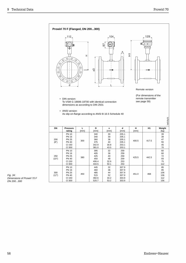
Prowirl 70 F (Flanged, DN 200...300)
DN Pressurerating
L[mm]
D[mm]
x[mm]
d[mm]
H[mm]
H1 Weight[kg]
200(8")
PN 10PN 16PN 25PN 40Cl 150Cl 300
300
340340360375
342.9381.0
30303640
30.843.5
205.1205.1205.1205.1203.1203.1
400.5 417.5
393947554570
250(10")
PN 10PN 16PN 25PN 40Cl 150Cl 300
380
395405425450
406.4444.5
32364048
32.650.1
259259259259253253
425.5 442.5
6060729375112
300(12")
PN 10PN 16PN 25PN 40Cl 150Cl 300
450
445460485515
482.6520.7
32364452
34.253.2
307.9307.9307.9307.9303.9303.9
451.0 468
8585106106112156
ba01
8y31
Remote version
(For dimensions of theremote transmittersee page 59)
• DIN version:To VSM G 18696-18700 with identical connectiondimensions as according to DIN 2501
• ANSI version:As slip-on-flange according to ANSI B 16.5 Schedule 40
Fig. 34:Dimensions of Prowirl 70 FDN 200...300
9 Technical Data Prowirl 70
56 Endress+Hauser
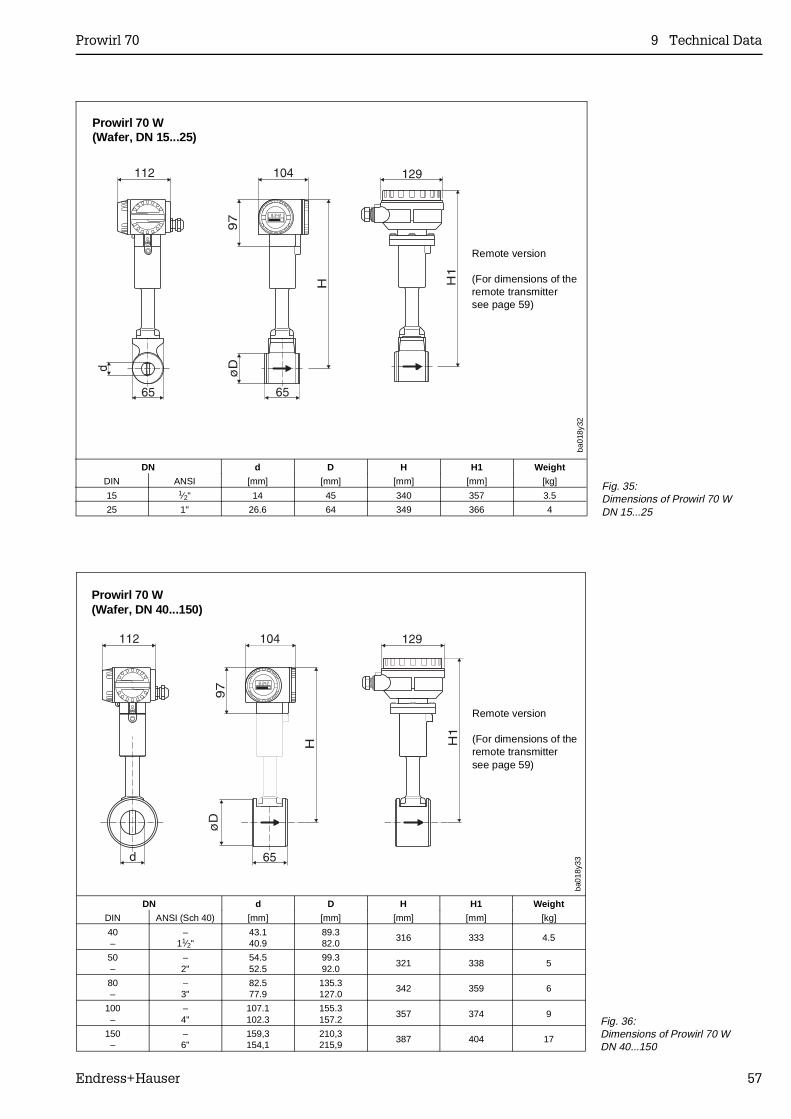
Prowirl 70 W(Wafer, DN 15...25)
DN d D H H1 Weight
DIN ANSI [mm] [mm] [mm] [mm] [kg]
15 1⁄2" 14 45 340 357 3.5
25 1" 26.6 64 349 366 4
ba01
8y32
Remote version
(For dimensions of theremote transmittersee page 59)
Fig. 35:Dimensions of Prowirl 70 WDN 15...25
Prowirl 70 W(Wafer, DN 40...150)
ba01
8y33
DN d D H H1 Weight
DIN ANSI (Sch 40) [mm] [mm] [mm] [mm] [kg]
40–
–11⁄2"
43.140.9
89.382.0
316 333 4.5
50–
–2"
54.552.5
99.392.0
321 338 5
80–
–3"
82.577.9
135.3127.0
342 359 6
100–
–4"
107.1102.3
155.3157.2
357 374 9
150–
–6"
159,3154,1
210,3215,9
387 404 17
Remote version
(For dimensions of theremote transmittersee page 59)
Fig. 36:Dimensions of Prowirl 70 WDN 40...150
Prowirl 70 9 Technical Data
Endress+Hauser 57
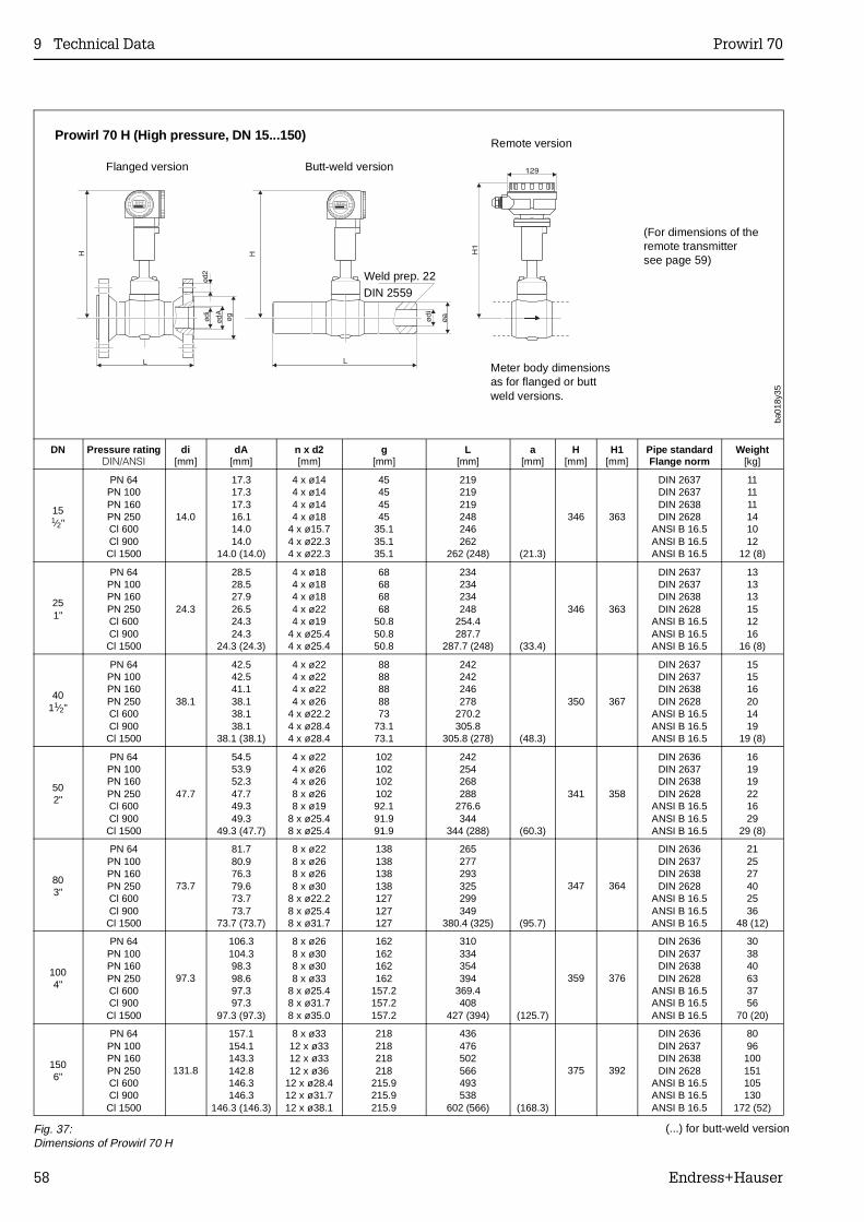
Prowirl 70 H (High pressure, DN 15...150)
DN Pressure ratingDIN/ANSI
di[mm]
dA[mm]
n x d2[mm]
g[mm]
L[mm]
a[mm]
H[mm]
H1[mm]
Pipe standardFlange norm
Weight[kg]
151⁄2"
PN 64PN 100PN 160PN 250Cl 600Cl 900Cl 1500
14.0
17.317.317.316.114.014.0
14.0 (14.0)
4 x ø144 x ø144 x ø144 x ø18
4 x ø15.74 x ø22.34 x ø22.3
45454545
35.135.135.1
219219219248246262
262 (248) (21.3)
346 363
DIN 2637DIN 2637DIN 2638DIN 2628
ANSI B 16.5ANSI B 16.5ANSI B 16.5
111111141012
12 (8)
251"
PN 64PN 100PN 160PN 250Cl 600Cl 900Cl 1500
24.3
28.528.527.926.524.324.3
24.3 (24.3)
4 x ø184 x ø184 x ø184 x ø224 x ø19
4 x ø25.44 x ø25.4
68686868
50.850.850.8
234234234248
254.4287.7
287.7 (248) (33.4)
346 363
DIN 2637DIN 2637DIN 2638DIN 2628
ANSI B 16.5ANSI B 16.5ANSI B 16.5
131313151216
16 (8)
4011⁄2"
PN 64PN 100PN 160PN 250Cl 600Cl 900Cl 1500
38.1
42.542.541.138.138.138.1
38.1 (38.1)
4 x ø224 x ø224 x ø224 x ø26
4 x ø22.24 x ø28.44 x ø28.4
8888888873
73.173.1
242242246278
270.2305.8
305.8 (278) (48.3)
350 367
DIN 2637DIN 2637DIN 2638DIN 2628
ANSI B 16.5ANSI B 16.5ANSI B 16.5
151516201419
19 (8)
502"
PN 64PN 100PN 160PN 250Cl 600Cl 900Cl 1500
47.7
54.553.952.347.749.349.3
49.3 (47.7)
4 x ø224 x ø264 x ø268 x ø268 x ø19
8 x ø25.48 x ø25.4
10210210210292.191.991.9
242254268288
276.6344
344 (288) (60.3)
341 358
DIN 2636DIN 2637DIN 2638DIN 2628
ANSI B 16.5ANSI B 16.5ANSI B 16.5
161919221629
29 (8)
803"
PN 64PN 100PN 160PN 250Cl 600Cl 900Cl 1500
73.7
81.780.976.379.673.773.7
73.7 (73.7)
8 x ø228 x ø268 x ø268 x ø30
8 x ø22.28 x ø25.48 x ø31.7
138138138138127127127
265277293325299349
380.4 (325) (95.7)
347 364
DIN 2636DIN 2637DIN 2638DIN 2628
ANSI B 16.5ANSI B 16.5ANSI B 16.5
212527402536
48 (12)
1004"
PN 64PN 100PN 160PN 250Cl 600Cl 900Cl 1500
97.3
106.3104.398.398.697.397.3
97.3 (97.3)
8 x ø268 x ø308 x ø308 x ø33
8 x ø25.48 x ø31.78 x ø35.0
162162162162
157.2157.2157.2
310334354394
369.4408
427 (394) (125.7)
359 376
DIN 2636DIN 2637DIN 2638DIN 2628
ANSI B 16.5ANSI B 16.5ANSI B 16.5
303840633756
70 (20)
1506"
PN 64PN 100PN 160PN 250Cl 600Cl 900Cl 1500
131.8
157.1154.1143.3142.8146.3146.3
146.3 (146.3)
8 x ø3312 x ø3312 x ø3312 x ø36
12 x ø28.412 x ø31.712 x ø38.1
218218218218
215.9215.9215.9
436476502566493538
602 (566) (168.3)
375 392
DIN 2636DIN 2637DIN 2638DIN 2628
ANSI B 16.5ANSI B 16.5ANSI B 16.5
8096100151105130
172 (52)
Weld prep. 22
DIN 2559
ba01
8y35
Flanged version Butt-weld version
Remote version
(For dimensions of theremote transmittersee page 59)
Meter body dimensionsas for flanged or buttweld versions.
Fig. 37:Dimensions of Prowirl 70 H
(...) for butt-weld version
9 Technical Data Prowirl 70
58 Endress+Hauser
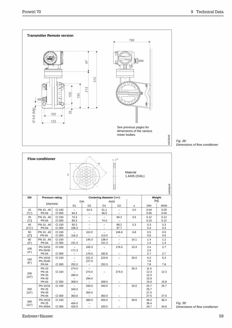
Transmitter Remote version
ba01
8y55
See previous pages fordimensions of the variousmeter bodies.
Fig. 38:Dimensions of flow conditioner
Material1.4435 (316L)
Flow conditioner
DN Pressure rating
DIN/ANSI
Centering diameter [mm] Weight[kg]DIN ANSI
D1 D2 D1 D2 s DIN ANSI
15(1⁄2")
PN 10...40PN 64
Cl 150Cl 300
–64.3
54.3–
51.156.5
––
2.0 0.040.05
0.030.04
25(1")
PN 10...40PN 64
Cl 150Cl 300
74.385.3
––
–74.3
69.2–
3.5 0.120.15
0.120.12
40(11⁄2")
PN 10...40PN 64
Cl 150Cl 300
95.3106.3
––
––
88.297.7
5.3 0.30.4
0.30.3
50(2")
PN 10...40PN 64
Cl 150Cl 300
–116.3
110.0–
–113.0
106.6–
6.8 0.50.6
0.50.5
80(3")
PN 10...40PN 64
Cl 150Cl 300
–151.3
145.3–
138.4151.3
––
10.1 1.41.4
1.21.4
100(4")
PN 10/16PN 25/40
PN 64
Cl 150
Cl 300
–171.3
–
165.3–
176.5
–
182.6
176.5
–
13.3 2.42.42.7
2.7
2.7
150(6")
PN 10/16PN 25/40
PN 64
Cl 150
Cl 300
––
252.0
221.0227.0
–
223.9
252.0
–
–
20.0 6.37.87.8
6.3
7.8
200(10")
PN 10PN 16PN 25PN 40PN 64
Cl 150
Cl 300
274.0–
280.0–
309.0
–274.0
–294.0
–
–
309.0
274.0
–
26.3 11.512.312.315.915.9
12.3
15.8
250(10")
PN 10/16PN 25PN 40PN 64
Cl 150
Cl 300
–340.0
–363.0
330.0–
355.0–
340.0
363.0
–
–
33.0 25.725.727.527.5
25.7
27.5
300(12")
PN 10/16PN 25
PN 40/64
Cl 150
Cl 300
–404.0420.0
380.0––
404.0
420.0
–
–
39.6 36.436.444.7
36.4
44.6
ba01
8y34
Fig. 39:Dimensions of flow conditioner
Prowirl 70 9 Technical Data
Endress+Hauser 59
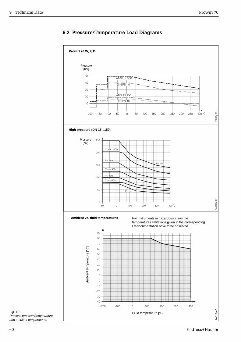
9.2 Pressure/Temperature Load Diagrams
Prowirl 70 W, F, D
Pressure[bar]
ba01
8y36
High pressure (DN 15...150)
Pressure[bar]
ba01
8y38
Fig. 40:Process pressure/temperatureand ambient temperatures
Fluid temperature [°C]
Am
bien
t tem
pera
ture
[°C
]
Ambient vs. fluid temperaturesba
018y
42For instruments in hazardous areas thetemperatures limitations given in the correspondingEx-documentation have to be observed.
9 Technical Data Prowirl 70
60 Endress+Hauser
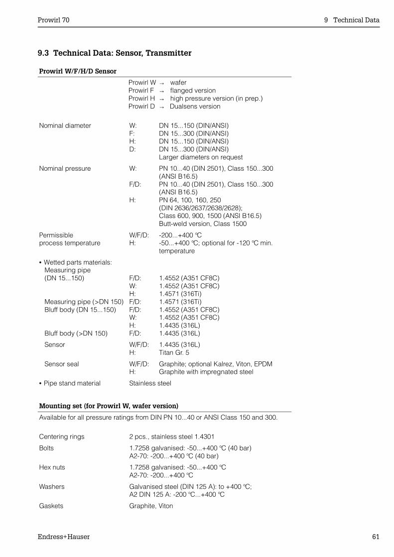
9.3 Technical Data: Sensor, Transmitter
Prowirl W/F/H/D Sensor
Prowirl W → waferProwirl F → flanged versionProwirl H → high pressure version (in prep.)Prowirl D → Dualsens version
Nominal diameter W: DN 15...150 (DIN/ANSI)F: DN 15...300 (DIN/ANSI)H: DN 15...150 (DIN/ANSI)D: DN 15...300 (DIN/ANSI)
Larger diameters on request
Nominal pressure W: PN 10...40 (DIN 2501), Class 150...300(ANSI B16.5)
F/D: PN 10...40 (DIN 2501), Class 150...300(ANSI B16.5)
H: PN 64, 100, 160, 250(DIN 2636/2637/2638/2628); Class 600, 900, 1500 (ANSI B16.5)Butt-weld version, Class 1500
Permissibleprocess temperature
W/F/D: -200...+400 °CH: -50...+400 °C; optional for -120 °C min.
temperature
• Wetted parts materials: Measuring pipe (DN 15...150)
Measuring pipe (>DN 150) Bluff body (DN 15...150)
Bluff body (>DN 150)
F/D: 1.4552 (A351 CF8C)W: 1.4552 (A351 CF8C)H: 1.4571 (316Ti)F/D: 1.4571 (316Ti)F/D: 1.4552 (A351 CF8C)W: 1.4552 (A351 CF8C)H: 1.4435 (316L)F/D: 1.4435 (316L)
Sensor W/F/D: 1.4435 (316L)H: Titan Gr. 5
Sensor seal W/F/D: Graphite; optional Kalrez, Viton, EPDMH: Graphite with impregnated steel
• Pipe stand material Stainless steel
Mounting set (for Prowirl W, wafer version)
Available for all pressure ratings from DIN PN 10...40 or ANSI Class 150 and 300.
Centering rings 2 pcs., stainless steel 1.4301
Bolts 1.7258 galvanised: -50...+400 °C (40 bar)A2-70: -200...+400 °C (40 bar)
Hex nuts 1.7258 galvanised: -50...+400 °CA2-70: -200...+400 °C
Washers Galvanised steel (DIN 125 A): to +400 °C;A2 DIN 125 A: -200 °C...+400 °C
Gaskets Graphite, Viton
Prowirl 70 9 Technical Data
Endress+Hauser 61
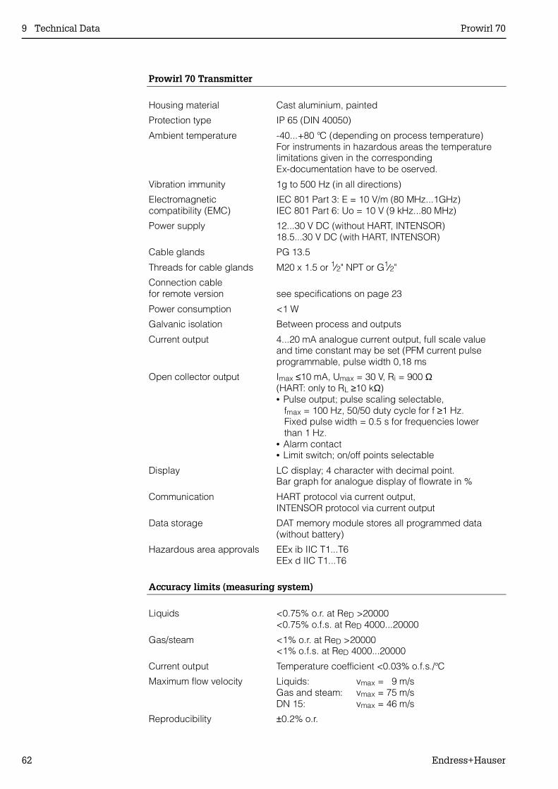
Prowirl 70 Transmitter
Housing material Cast aluminium, painted
Protection type IP 65 (DIN 40050)
Ambient temperature -40...+80 °C (depending on process temperature)For instruments in hazardous areas the temperaturelimitations given in the correspondingEx-documentation have to be oserved.
Vibration immunity 1g to 500 Hz (in all directions)
Electromagneticcompatibility (EMC)
IEC 801 Part 3: E = 10 V/m (80 MHz...1GHz)IEC 801 Part 6: Uo = 10 V (9 kHz...80 MHz)
Power supply 12...30 V DC (without HART, INTENSOR) 18.5...30 V DC (with HART, INTENSOR)
Cable glands PG 13.5
Threads for cable glands M20 x 1.5 or 1⁄2" NPT or G1⁄2"
Connection cablefor remote version see specifications on page 23
Power consumption <1 W
Galvanic isolation Between process and outputs
Current output 4...20 mA analogue current output, full scale valueand time constant may be set (PFM current pulseprogrammable, pulse width 0,18 ms
Open collector output Imax ≤10 mA, Umax = 30 V, Ri = 900 Ω(HART: only to RL ≥10 kΩ)• Pulse output; pulse scaling selectable, fmax = 100 Hz, 50/50 duty cycle for f ≥1 Hz. Fixed pulse width = 0.5 s for frequencies lower than 1 Hz.• Alarm contact• Limit switch; on/off points selectable
Display LC display; 4 character with decimal point.Bar graph for analogue display of flowrate in %
Communication HART protocol via current output,INTENSOR protocol via current output
Data storage DAT memory module stores all programmed data(without battery)
Hazardous area approvals EEx ib IIC T1...T6EEx d IIC T1...T6
Accuracy limits (measuring system)
Liquids <0.75% o.r. at ReD >20000<0.75% o.f.s. at ReD 4000...20000
Gas/steam <1% o.r. at ReD >20000<1% o.f.s. at ReD 4000...20000
Current output Temperature coefficient <0.03% o.f.s./°C
Maximum flow velocity Liquids: vmax = 9 m/sGas and steam: vmax = 75 m/sDN 15: vmax = 46 m/s
Reproducibility ±0.2% o.r.
9 Technical Data Prowirl 70
62 Endress+Hauser
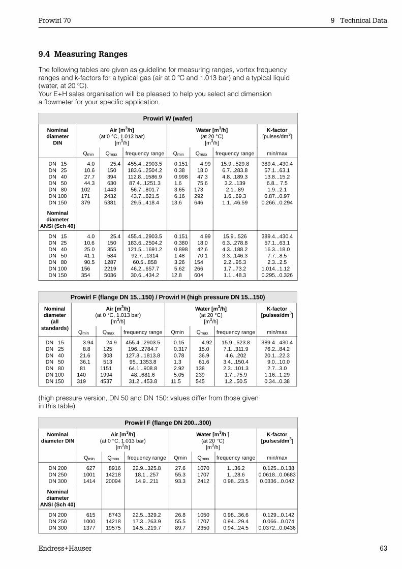
9.4 Measuring Ranges
The following tables are given as guideline for measuring ranges, vortex frequencyranges and k-factors for a typical gas (air at 0 °C and 1.013 bar) and a typical liquid(water, at 20 °C).Your E+H sales organisation will be pleased to help you select and dimensiona flowmeter for your specific application.
Prowirl W (wafer)
Nominaldiameter
DIN
Air [m 3/h](at 0 °C, 1.013 bar)
[m3/h]
Water [m 3/h](at 20 °C)
[m3/h]
K-factor[pulses/dm3]
Qmin Qmax frequency range Qmin Qmax frequency range min/max
DN 15DN 25DN 40DN 50DN 80DN 100DN 150
4.0 10.6 27.7 44.3 102 171 379
25.4 150 394 630 1443 2432 5381
455.4...2903.5183.6...2504.2112.8...1586.987.4...1251.356.7...801.743.7...621.529.5...418.4
0.151 0.38 0.998 1.6 3.65 6.16 13.6
4.99 18.0 47.3 75.6 173 292 646
15.9...529.86.7...283.84.8...189.33.2...1392.1...89
1.6...69.31.1...46.59
389.4...430.457.1...63.113.8...15.26.8... 7.51.9...2.1
0.87...0.970.266...0.294
Nominaldiameter
ANSI (Sch 40)
DN 15DN 25DN 40DN 50DN 80DN 100DN 150
4.0 10.6 25.0 41.1 90.5 156 354
25.4 150 355 584 1287 2219 5036
455.4...2903.5183.6...2504.2121.5...1691.2
92.7...131460.5...858
46.2...657.730.6...434.2
0.151 0.380 0.898 1.48 3.26 5.62 12.8
4.99 18.0 42.6 70.1 154 266 604
15.9...5266.3...278.84.3...188.23.3...146.32.2...95.31.7...73.21.1...48.3
389.4...430.457.1...63.116.3...18.0
7.7...8.52.3...2.5
1.014...1.12 0.295...0.326
Prowirl F (flange DN 15...150) / Prowirl H (high pressure DN 15...150)
Nominaldiameter
(allstandards)
Air [m 3/h](at 0 °C, 1.013 bar)
[m3/h]
Water [m 3/h](at 20 °C)
[m3/h]
K-factor[pulses/dm 3]
Qmin Qmax frequency range Qmin Qmax frequency range min/max
DN 15DN 25DN 40DN 50DN 80DN 100DN 150
3.94 8.8 21.6 36.1 81 140 319
24.9 125 308 513 1151 1994 4537
455.4...2903.5196...2784.7
127.8...1813.895...1353.864.1...908.848...681.6
31.2...453.8
0.15 0.317 0.78 1.3 2.92 5.05 11.5
4.92 15.0 36.9 61.6 138 239 545
15.9...523.87.1...311.94.6...202
3.4...150.42.3...101.31.7...75.91.2...50.5
389.4...430.476.2...84.220.1...22.3 9.0...10.02.7...3.0
1.16...1.290.34...0.38
Prowirl F (flange DN 200...300)
Nominaldiameter DIN
Air [m 3/h](at 0 °C, 1.013 bar)
[m3/h]
Water [m 3/h ](at 20 °C)
[m3/h]
K-factor[pulses/dm 3]
Qmin Qmax frequency range Qmin Qmax frequency range min/max
DN 200DN 250DN 300
62710011414
89161421820094
22.9...325.818.1...25714.9...211
27.655.393.3
107017072412
1...36.21...28.6
0.98...23.5
0.125...0.1380.0618...0.06830.0336...0.042
Nominaldiameter
ANSI (Sch 40)
DN 200DN 250DN 300
61510001377
87431421819575
22.5...329.217.3...263.914.5...219.7
26.855.589.7
105017072350
0.98...36.60.94...29.40.94...24.5
0.129...0.142 0.066...0.0740.0372...0.0436
(high pressure version, DN 50 and DN 150: values differ from those givenin this table)
Prowirl 70 9 Technical Data
Endress+Hauser 63

Prowirl 70
64 Endress+Hauser
Index
Index
AAccess code . . . . . . . . . . . . . . . 42Accuracy limits . . . . . . . . . . . . . . 62Alarm output (see: Fault output) . . . . . . . . 39Amplification . . . . . . . . . . . . . . . 46Applications . . . . . . . . . . . . . . 7, 10
BBack pressure, minimum (liquids) . . . . . . . 12
CCable lengths (mounting) . . . . . . . . . . 15Cavitation (liquids) . . . . . . . . . . . . . 12Code number selection . . . . . . . . . . . 42Commissioning . . . . . . . . . . . . . . 24Compressed air chambers . . . . . . . . . . 12Condensate, removal . . . . . . . . . . . . 12Connection (electrical) . . . . . . . . . . . 21Connection diagrams . . . . . . . . . . . . 21Correct usage . . . . . . . . . . . . . . . 5
DDangerous chemicals . . . . . . . . . . . . 54Dimensions . . . . . . . . . . . . . . . . 55Display . . . . . . . . . . . . . . . . . 25Display and operating elements . . . . . . . . 25Display configuration . . . . . . . . . . . . 41
EElectrical connection . . . . . . . . . . . . 21Engineering units . . . . . . . . . . . . . 32Error limits . . . . . . . . . . . . . . . . 62Error messages (instrument status) . . . . . . 43Expansion coefficient (thermal) . . . . . . . . 46Expansion tanks . . . . . . . . . . . . . . 12Extended menu . . . . . . . . . . . . 29, 30
F
Factory settings . . . . . . . . . . . . . . 29Failsafe mode (current output) . . . . . . . . 38Fault output (open collector) . . . . . . . . . 39Flow conditioner . . . . . . . . . . . . . . 13Flow profile . . . . . . . . . . . . . . . . 13Fluid . . . . . . . . . . . . . . . . . . 45Functions (description) . . . . . . . . . . . 31Functions (overview) . . . . . . . . . . . . 29Functions, selecting . . . . . . . . . . . . 26FXN 671 power supply module . . . . . . . . 50
GGas separator . . . . . . . . . . . . . . 12Gaskets (internal diameter) . . . . . . . . . 16Gateway . . . . . . . . . . . . . . . . 50
HHART communicater . . . . . . . . . . . . 48HART interface . . . . . . . . . . . . . . 47HART programming matrix . . . . . . . . . 49Home position . . . . . . . . . . . . . . 26
IInlet sections . . . . . . . . . . . . . . . 13Installation . . . . . . . . . . . . . . . . 13Installation site . . . . . . . . . . . . . . 14Instrument status (error messages) . . . . . . 43Insulation (pipeline) . . . . . . . . . . . . 14INTENSOR . . . . . . . . . . . . . . . 50Interference signals . . . . . . . . . . . . 46
KK-factor (sensor) . . . . . . . . . . . . . 45
LLimit switch (open collector) . . . . . . . . . 39Load resistance (current output) . . . . . . . 23Local display (mounting/turning) . . . . . . . 18
MMatrix (E+H programming matrix) . . . . . . 49Measured values (actual), call up . . . . . . . 31Measuring pipe material (expansion coefficient) . 46Measuring principle . . . . . . . . . . . . . 7Measuring ranges (Qmin, Qmax) . . . . . . . 63Measuring system (design) . . . . . . . . . 10Measuring system data . . . . . . . . . . . 45Minimum space (mounting) . . . . . . . . . 15Mounting set (wafer version) . . . . . . . . . 16Mounting the meter body . . . . . . . . . . 16
NNominal current . . . . . . . . . . . . . . 38Nominal diameter change (flowmeter) . . . . . 45Nominal frequency (pulse output) . . . . . . . 40
OOpen collector configuring . . . . . . . . . 39Operation . . . . . . . . . . . . . . . . 25Outlet sections . . . . . . . . . . . . . . 13
Prowirl 70
Endress+Hauser 65
PParameters, changing . . . . . . . . . . . . 26PFM pulse (current output) . . . . . . . . . . 37Pipeline insulation . . . . . . . . . . . . . 14Plant vibration . . . . . . . . . . . . . . . 46Pressure pulses/Measuring accuracy . . . . . . 12Process pressure curves . . . . . . . . . . 60Process temperature . . . . . . . . . . . . 46Product (selecting) . . . . . . . . . . . . . 45Programming (enabling/locking) . . . . . . . . 27Programming matrix . . . . . . . . . . . . 49Protection IP 65 . . . . . . . . . . . . . . 11Protective disks (transport) . . . . . . . . . . 16Prowirl 70 measuring system . . . . . . . . . 8Pulse output (open collector) . . . . . . . . . 39Pulse scaling . . . . . . . . . . . . . . . 39Pushbuttons (local operation) . . . . . . . . . 25
QQuick setup menu . . . . . . . . . . . . . 28
RRepairs . . . . . . . . . . . . . . . . 6, 54
SSafety instructions . . . . . . . . . . . . . 2Simulation (current) . . . . . . . . . . . . . 38Simulation (pulse output) . . . . . . . . . . 39Software versions . . . . . . . . . . . . . 44Switch on/off point (limit value) . . . . . . . . 40System parameters . . . . . . . . . . . . . 42System units . . . . . . . . . . . . . . . 32
TTechnical data . . . . . . . . . . . . . . . 55Technical data (mounting set) . . . . . . . . . 61Technical data (sensor) . . . . . . . . . . . 61Technical data (transmitter) . . . . . . . . . 62Technical units (user defined) . . . . . . . 33, 36Temperature ranges . . . . . . . . . 11, 61, 62Thermal expansion coefficient (thermal) . . . . . 46Time constant . . . . . . . . . . . . . . . 38Totaliser . . . . . . . . . . . . . . . . . 31Totaliser overflow . . . . . . . . . . . . . . 31Totaliser reset to zero . . . . . . . . . . . . 41Transmitter housing (unscrewing) . . . . . . . 15
VVibration . . . . . . . . . . . . . . . . . 46Vortex frequency . . . . . . . . . . . . . . 7
WWeights . . . . . . . . . . . . . . . . . 55
Index Prowirl 70
66 Endress+Hauser


Europe
Austria Endress+Hauser Ges.m.b.H.WienTel. (01) 88056-0, Fax (01) 88056-35
Belarus BelorgsintezMinskTel. (0172) 508473, Fax (0172) 508583
Belgium / Luxembourg Endress+Hauser N.V.BrusselsTel. (02) 2480600, Fax (02) 2480553
BulgariaINTERTECH-AUTOMATIONSofiaTel. (02) 664869, Fax (02) 9631389
Croatia Endress+Hauser GmbH+Co.ZagrebTel. (01) 6637785, Fax (01) 6637823
CyprusI+G Electrical Services Co. Ltd.NicosiaTel. (02) 484788, Fax (02) 484690
Czech Republic Endress+Hauser GmbH+Co.PrahaTel. (026) 6784200, Fax (026) 6784179
Denmark Endress+Hauser A/SSøborgTel. (70) 131132, Fax (70) 132133
EstoniaELVI-AquaTartuTel. (7) 441638, Fax (7) 441582
Finland Endress+Hauser OyHelsinkiTel. (0204) 83160, Fax (0204) 83161
France Endress+Hauser S.A.HuningueTel. (389) 696768, Fax (389) 694802
Germany Endress+Hauser Messtechnik GmbH+Co.Weil am RheinTel. (07621) 975-01, Fax (07621) 975-555
Great Britain Endress+Hauser Ltd.ManchesterTel. (0161) 2865000, Fax (0161) 9981841
GreeceI & G Building Services Automation S.A.AthensTel. (01) 9241500, Fax (01) 9221714
HungaryMile Ipari-ElektroBudapestTel. (01) 4319800, Fax (01) 4319817
IcelandBIL ehfReykjavikTel. (05) 619616, Fax (05) 619617
IrelandFlomeaco Company Ltd.KildareTel. (045) 868615, Fax (045) 868182
Italy Endress+Hauser S.p.A.Cernusco s/N MilanoTel. (02) 921921, Fax (02) 92107153
LatviaRino TKRigaTel. (07) 315087, Fax (07) 315084
LithuaniaUAB "Agava"KaunasTel. (07) 202410, Fax (07) 207414
Netherland Endress+Hauser B.V.NaardenTel. (035) 6958611, Fax (035) 6958825
Norway Endress+Hauser A/STranbyTel. (032) 859850, Fax (032) 859851
Poland Endress+Hauser Polska Sp. z o.o.WarszawyTel. (022) 7201090, Fax (022) 7201085
PortugalTecnisis, LdaCacémTel. (21) 4267290, Fax (21) 4267299
RomaniaRomconseng S.R.L.BucharestTel. (01) 4101634, Fax (01) 4112501
Russia Endress+Hauser Moscow OfficeMoscowTel. (095) 1587564, Fax (095) 1589871
SlovakiaTranscom Technik s.r.o.BratislavaTel. (7) 44888684, Fax (7) 44887112
Slovenia Endress+Hauser D.O.O.LjubljanaTel. (061) 5192217, Fax (061) 5192298
Spain Endress+Hauser S.A.Sant Just DesvernTel. (93) 4803366, Fax (93) 4733839
Sweden Endress+Hauser ABSollentunaTel. (08) 55511600, Fax (08) 55511655
Switzerland Endress+Hauser AGReinach/BL 1Tel. (061) 7157575, Fax (061) 7111650
TurkeyIntek Endüstriyel Ölcü ve Kontrol SistemleriIs-tanbulTel. (0212) 2751355, Fax (0212) 2662775
UkrainePhotonika GmbHKievTel. (44) 26881, Fax (44) 26908
Yugoslavia Rep.Meris d.o.o.BeogradTel. (11) 4441966, Fax (11) 4441966
Africa
EgyptAnasiaHeliopolis/CairoTel. (02) 4179007, Fax (02) 4179008
MoroccoOussama S.A.CasablancaTel. (02) 241338, Fax (02) 402657
South Africa Endress+Hauser Pty. Ltd.SandtonTel. (011) 4441386, Fax (011) 4441977
TunisiaControle, Maintenance et RegulationTunisTel. (01) 793077, Fax (01) 788595
America
Argentina Endress+Hauser Argentina S.A.Buenos AiresTel. (01) 145227970, Fax (01) 145227909
BoliviaTritec S.R.L.CochabambaTel. (042) 56993, Fax (042) 50981
Brazil Samson Endress+Hauser Ltda.Sao PauloTel. (011) 50313455, Fax (011) 50313067
Canada Endress+Hauser Ltd.Burlington, OntarioTel. (905) 6819292, Fax (905) 6819444
Chile Endress+Hauser Chile Ltd.SantiagoTel. (02) 3213009, Fax (02) 3213025
ColombiaColsein Ltda.Bogota D.C.Tel. (01) 2367659, Fax (01) 6104186
Costa RicaEURO-TEC S.A.San JoseTel. (02) 961542, Fax (02) 961542
EcuadorInsetec Cia. Ltda.QuitoTel. (02) 269148, Fax (02) 461833
GuatemalaACISA Automatizacion Y ControlIndustrial S.A.Ciudad de Guatemala, C.A.Tel. (03) 345985, Fax (03) 327431
Mexico Endress+Hauser S.A. de C.V.Mexico CityTel. (5) 5682405, Fax (5) 5687459
ParaguayIncoel S.R.L.AsuncionTel. (021) 213989, Fax (021) 226583
UruguayCircular S.A.MontevideoTel. (02) 925785, Fax (02) 929151
USA Endress+Hauser Inc.Greenwood, IndianaTel. (317) 535-7138, Fax (317) 535-8498
VenezuelaControval C.A.CaracasTel. (02) 9440966, Fax (02) 9444554
Asia
China Endress+Hauser Shanghai Instrumentation Co. Ltd.ShanghaiTel. (021) 54902300, Fax (021) 54902303
Endress+Hauser Beijing OfficeBeijingTel. (010) 68344058, Fax (010) 68344068
Hong Kong Endress+Hauser HK Ltd.Hong KongTel. 25283120, Fax 28654171
India Endress+Hauser (India) Pvt Ltd.MumbaiTel. (022) 8521458, Fax (022) 8521927
IndonesiaPT Grama BazitaJakartaTel. (21) 7975083, Fax (21) 7975089
Japan Sakura Endress Co. Ltd.TokyoTel. (0422) 540613, Fax (0422) 550275
Malaysia Endress+Hauser (M) Sdn. Bhd.Petaling Jaya, Selangor Darul EhsanTel. (03) 7334848, Fax (03) 7338800
PakistanSpeedy AutomationKarachiTel. (021) 7722953, Fax (021) 7736884
Papua-NeuguineaSBS Electrical Pty LimitedPort MoresbyTel. 3251188, Fax 3259556
Philippines Endress+Hauser Philippines Inc.Metro ManilaTel. (2) 3723601-05, Fax (2) 4121944
Singapore Endress+Hauser (S.E.A.) Pte., Ltd.SingaporeTel. 5668222, Fax 5666848
South Korea Endress+Hauser (Korea) Co., Ltd.SeoulTel. (02) 6587200, Fax (02) 6592838
TaiwanKingjarl CorporationTaipei R.O.C.Tel. (02) 27183938, Fax (02) 27134190
Thailand Endress+Hauser Ltd.BangkokTel. (2) 9967811-20, Fax (2) 9967810
VietnamTan Viet Bao Co. Ltd.Ho Chi Minh CityTel. (08) 8335225, Fax (08) 8335227
IranPATSA Co.TehranTel. (021) 8754748, Fax (021) 8747761
IsraelInstrumetrics Industrial Control Ltd.NetanyaTel. (09) 8357090, Fax (09) 8350619
JordanA.P. Parpas Engineering S.A.AmmanTel. (06) 4643246, Fax (06) 4645707
Kingdom of Saudi ArabiaAnasia Ind. AgenciesJeddahTel. (02) 6710014, Fax (02) 6725929
LebanonNetwork EngineeringJbeilTel. (3) 944080, Fax (9) 548038
Sultanate of OmanMustafa Sultan Science & Industry Co. LLC.RuwiTel. 602009, Fax 607066
United Arab EmiratesDescon Trading EST.DubaiTel. (04) 2653651, Fax (04) 2653264
YemenYemen Company for Ghee and Soap IndustryTaizTel. (04) 230664, Fax (04) 212338
Australia + New Zealand
AustraliaALSTOM Australia LimitedMilperraTel. (02) 97747444, Fax (02) 97744667
New ZealandEMC Industrial Group LimitedAucklandTel. (09) 4155110, Fax (09) 4155115
All other countries
Endress+Hauser GmbH+Co.Instruments InternationalD-Weil am RheinGermanyTel. (07621) 975-02, Fax (07621) 975345
Members of the Endress+Hauser group
http://www.endress.com
01.01