Embed Size (px)
Citation preview

B680H


Leggere completamente questo manuale di istruzioni prima di iniziare l’installazione del prodotto.
Il simbolo evidenzia le note importanti per la sicurezza delle persone e l’integrità dell’automazione.
Il simbolo richiama l’attenzione sulle note riguardanti le caratteristiche od il funzionamento del prodotto.
Read this instruction manual to the letter before you begin to install the product.
Symbol highlights notes that are important for people’s safety and for the good condition of the automated system.
Symbol draws your attention to the notes about the product’s characteristics or operation.
Lire ce manuel d’instructions dans son entier avant de commencer l’installation du produit.
Le symbole met en évidence les remarques pour la sécurité des personnes et le parfait état de l’automatisme.
Le symbole attire l’attention sur les remarques concernant les caractéristiques ou le fonctionnement du produit.
Vor der Installation des Produkts sind die Anweisungen vollständig zu lesen.
Mit dem Symbol sind wichtige Anmerkungen für die Sicherheit der Personen und den störungsfreien Betrieb der
Automation gekennzeichnet.
Mit dem Symbol wird auf Anmerkungen zu den Eigenschaften oder dem Betrieb des Produkts verwiesen.
Lean completamente este manual de instrucciones antes de empezar la instalación del producto.
El símbolo identifica notas importantes para la seguridad de las personas y para la integridad de la automa-
ción.
El símbolo llama la atención sobre las notas relativas a las características o al funcionamiento del producto.
Lees deze instructiehandleiding helemaal door alvorens het product te installeren.
Het symbool is een aanduiding van opmerkingen die belangrijk zijn voor de veiligheid van personen en voor een
goede automatische werking.
Het symbool vestigt de aandacht op opmerkingen over de eigenschappen of de werking van het product.


1
EN
GL
ISH
INDEXB680H AUTOMATED SYSTEM1. TECHNICAL SPECIFICATIONS ............................................................................................................................................................3
1.1 Summary table ...............................................................................................................................................................................31.2 Key Fig. 5 ........................................................................................................................................................................................31.3 Key Fig. 6 ........................................................................................................................................................................................3
2. ELECTRICAL PREPARATIONS (standard system) ............................................................................................................................33. BARRIER DIMENSIONS ........................................................................................................................................................................34. INSTALLING THE AUTOMATED SYSTEM ...........................................................................................................................................3
4.1 Preliminary checks .......................................................................................................................................................................34.2 Walling in the foundation plate ...................................................................................................................................................34.3 Electrical preparations .................................................................................................................................................................34.4 Mechanical installation ................................................................................................................................................................34.5 Fixing the plunging pistons .........................................................................................................................................................44.6 Balancing the barrier ....................................................................................................................................................................4
5. START-UP ...............................................................................................................................................................................................45.1 Connecting the control equipment .............................................................................................................................................45.2 Testing the automated system ....................................................................................................................................................4
6. MANUAL OPERATION ..........................................................................................................................................................................47. RESTORING NORMAL OPERATION ....................................................................................................................................................48. MAINTENANCE .....................................................................................................................................................................................4
8.1 Topping up the oil .........................................................................................................................................................................48.2 Air bleeding ...................................................................................................................................................................................4
9. REVERSING THE OPENING DIRECTION ............................................................................................................................................410. ACCESSORIES ....................................................................................................................................................................................5
10.1 Installing a photocell .................................................................................................................................................................510.2 Installing the bar light kit ...........................................................................................................................................................510.3 Installation of a receiver antenna..............................................................................................................................................5
11. REPAIRS ...............................................................................................................................................................................................5E680 CONTROL BOARD1. WARNINGS ............................................................................................................................................................................................62. DESCRIPTION OF THE COMPONENTS ..............................................................................................................................................63. TECHNICAL SPECIFICATIONS ............................................................................................................................................................64. ELECTRICAL CONNECTIONS ..............................................................................................................................................................7
4.1 Terminal board J1 (inputs) ...........................................................................................................................................................74.2 Terminal board J2 (outputs).........................................................................................................................................................84.3 Terminal board J3 (external flashing lamp) ...............................................................................................................................84.4 Terminal board J4 (loop detector) ..............................................................................................................................................84.5 Connector J5 (Motor)....................................................................................................................................................................84.6 Connector J7 (Encoder) ...............................................................................................................................................................84.7 Connector J10 (Radio) ..................................................................................................................................................................84.8 Connector J11 (Beam break-out sensor) ...................................................................................................................................84.9 Connector J12 (Emergency battery) ...........................................................................................................................................84.10 Connector J13 (36VDC Power Supply) .....................................................................................................................................84.11 Connector J15 (flashing traffic light) ........................................................................................................................................8
5. PROGRAMMING ....................................................................................................................................................................................85.1 Basic configuration .......................................................................................................................................................................95.2 Changing the predefined parameters set ................................................................................................................................105.3 BUS accessories menu ..............................................................................................................................................................11
6. Advanced Configuration ....................................................................................................................................................................126.1 Configuring the loop detector ...................................................................................................................................................136.2 Expert Configuration ..................................................................................................................................................................146.3 Pre-Defined Parameter Sets ......................................................................................................................................................176.4 “Expert” default parameters .....................................................................................................................................................18
7. START-UP .............................................................................................................................................................................................187.1 Verifying the diagnostic LEDs ...................................................................................................................................................187.2 Setup .............................................................................................................................................................................................18
8. TESTING THE AUTOMATED SYSTEM ...............................................................................................................................................189. MASTER/SLAVE CONFIGURATION ...................................................................................................................................................1910. INTERLOCK CONNECTION ..............................................................................................................................................................1911. OPERATING LOGICS TABLE ............................................................................................................................................................2012. BALANCING TABLES .......................................................................................................................................................................2313. DEFAULT SELECTION TABLES .......................................................................................................................................................24
Raccolta immagini - Pictures collection - Collection de Figure - Conjunto de imagenes - Photo Kollection - Fotoverzameling

2
EN
GL
ISH
CE DECLARATION OF CONFORMITY FOR MACHINES(DIRECTIVE 2006/42/EC)
Manufacturer: FAAC S.p.A.
Address: Via Calari 10 - 40069 Zola Predosa BOLOGNA - ITALY
Declares that: The operator mod. B680H with control board E680
•isbuilttobeintegratedintoamachineortobeassembledwithothermachinerytocreateamachineunderthe provisions of Directive 2006/42/EC;
•conformstotheessentialsafetyrequirementsofthefollowingEECdirectives:
2006/95/ECLowVoltageDirective 2004/108/ECElectromagneticCompatibilityDirective
and also declares that itisprohibitedtoputintoservicethemachineryuntilthemachineinwhichitwillbeintegratedorofwhichitwillbecomeacomponenthasbeenidentifiedanddeclaredasconformingtotheconditions of Directive Directive 2006/42/EC.
Bologna,1October2011 TheManagingDirector
A. Marcellan
WARNINGS FOR THE INSTALLERGENERAL SAFETY OBLIGATIONS
1) ATTENTION! To ensure the safety of people, it is important that you read all the following instructions. Incorrect installation or incorrect use of the product could cause serious harm to people.
2) Carefullyreadtheinstructionsbeforebeginningtoinstalltheproduct.. 3) Donot leavepackingmaterials(plastic,polystyrene,etc.)withinreachof
childrenassuchmaterialsarepotentialsourcesofdanger. 4) Storetheseinstructionsforfuturereference. 5) Thisproductwasdesignedandbuiltstrictlyfortheuseindicatedinthisdo-
cumentation.Anyotheruse,notexpresslyindicatedhere,couldcompromisethegoodcondition/operationoftheproductand/orbeasourceofdanger.
6) FAACdeclinesallliabilitycausedbyimproperuseoruseotherthanthatforwhichtheautomatedsystemwasintended.
7) Donotinstalltheequipmentinanexplosiveatmosphere:thepresenceofinflammablegasorfumesisaseriousdangertosafety.
8) ThemechanicalpartsmustconformtotheprovisionsofStandardsEN12604andEN12605.Fornon-EUcountries,toobtainanadequatelevelofsafety,theStandardsmentionedabovemustbeobserved,inadditiontonationallegalregulations..
9) FAACisnotresponsibleforfailuretoobserveGoodTechniqueinthecon-structionoftheclosingelementstobemotorised,orforanydeformationthatmayoccurduringuse.
10) TheinstallationmustconformtoStandardsEN12453andEN12445.Fornon-EUcountries,toobtainanadequatelevelofsafety,theStandardsmen-tionedabovemustbeobserved,inadditiontonationallegalregulations..
11) Beforeattemptinganyworkonthesystem,cutoutelectricalpower.12) Themainspowersupplyof theautomatedsystemmustbefittedwithan
all-poleswitchwithcontactopeningdistanceof3mmorgreater.Useofa6Athermalbreakerwithall-polecircuitbreakisrecommended.
13) Makesurethatadifferentialswitchwiththresholdof0.03Aisfittedupstreamofthesystem.
14) Makesurethattheearthingsystemisperfectlyconstructed,andconnectmetalpartsoftheclosingelementstoit.
15) Theautomatedsystemfeaturesabuilt-inanti-crushingsafetydeviceconsistingofatorquecontrol.Itishowevernecessarytocheckitstrippingthreshold,as provided for in the Standards described in point 10.
16) Thesafetydevices(EN12978standard)protectanydangerareasagainstmechanicalmovementRisks,suchascrushing,dragging,andshearing.
17) Foreachsystem,werecommendusingatleastonesignallight(e.g.:FAA-CLEDorintegratedflashingtrafficlight)aswellasawarningsignsecurelyfixedtothestructure,togetherwiththedevicesdescribedinpoint“16”.
18) FAACdeclinesallliabilityasconcernssafetyandefficientoperationoftheautomatedsystem,ifsystemcomponentsnotproducedbyFAACareused.
19) Formaintenance,strictlyuseoriginalpartsbyFAAC.20) Donotinanywaymodifythecomponentsoftheautomatedsystem21) Theinstallershallsupplyallinformationconcerningmanualoperationofthe
systemincaseofanemergency,andshallhandovertotheUsertheleafletsuppliedwiththeproduct.
22) Donotallowchildrenoradultstostayneartheproductwhileitisoperating.23) Keepradiocontrolsorotherpulsegeneratorsawayfromchildren,toprevent
theautomatedsystemfrombeingactivatedinvoluntarily.24) Transitingispermittedonlywhentheautomatedsystemisstationary.25) TheUsermustnotattemptanykindofrepairordirectactionwhateverand
contactqualifiedpersonnelonly.26) Maintenance:checkatleastevery6monthstheefficiencyofthesystem,
particularlytheefficiencyofthesafetydevices(including,whereforeseen,theoperatorthrustforce)andofthereleasedevices.
27) Anythingnotexpresslyspecifiedintheseinstructionsisnotpermitted.
3
EN
GL
ISH
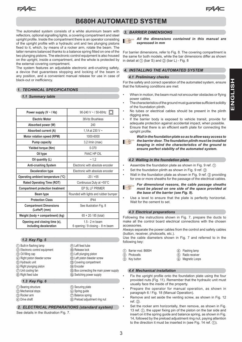
B680H AUTOMATED SYSTEMTheautomated system consists of awhite aluminiumbeamwithreflectors,optionalsignallinglights,acoveringcompartmentandsteeluprightprofile.Insidethecompartmentthereisanoperatorconsistingoftheuprightprofilewithahydraulicunitandtwoplungingpistonsfixedtoit,which,bymeansofarockerarm,rotatethebeam.Thelatterremainsbalancedthankstoabalancespringfittedononeofthetwoplungingpistons.Theelectroniccontrolequipmentisalsohousedontheupright,insideacompartment,andthewholeisprotectedbytheexternalcoveringcompartment.Thesystem featuresanadjustableelectronicanti-crushingsafety,a device that guarantees stopping and locking of the beam inanyposition,andaconvenientmanual release foruse incaseof black-outorinefficiency.
1. TECHNICAL SPECIFICATIONS1.1 Summary table
Power supply (V ~ / Hz) 90-240 V ~ / 50-60Hz
Electric Motor 36VdcBrushless
Absorbed power (W) 240
Absorbed current (A) 1,1Aat230V~
Motor rotation speed (RPM) 1000-6000
Pump capacity 3,2l/min(max)
Yielded torque (Nm) 0-370
Oil type FAAC HP OIL
Oil quantity (L) ~1,2
Anti-crushing System Electronicwithabsoluteencoder
Deceleration type Electronicwithabsoluteencoder
Operating ambient temperature (°C) -20 / +55
Rated Operating Time (ROT) ContinuousDutyat+55°C
Compartment protection treatment EP SL LF PRIMER
Beam type Roundedwithlightsandrubberbumper
Protection Class IP44
Compartment Dimensions (LxHxP) (mm)
SeeillustrationFig.8
Weight (body + compartment) (kg) 65+20/85(total)
Opening and closing time (s),including deceleration
1.5 - 2 m beam 6opening/9closing-8mbeam
a Built-inflashinglampb Electroniccontrolequipmentc Oilfillingcapd RightpistonbleederscreweHydraulicunitfRightplungingpistongUnitcoolingfanhRightfeedtube
iLeftfeedtubej Release lockkLeftplungingpistonl Left piston bleeder screwmCoveringcompartmentn EncoderoBoxconnectingthemainpowersupplypSwitchingpowersupply
a Bearingstructureb Mechanical stopsc Rocker armd Drive shaft
eSecuringplatefSpringguidegBalancespringhPreloadadjustmentringnut
1.2 Key Fig. 5
1.3 Key Fig. 6
2. ELECTRICAL PREPARATIONS (standard system)SeedetailsintheillustrationFig.7.
3. BARRIER DIMENSIONSAll the dimensions contained in this manual are expressed in mm
Forbarrierdimensions,refertoFig.8.Thecoveringcompartmentisthesameforbothmodels,whilethebardimensionsdifferasshownin detail at a(barS)andb(barL)-Fig.8
4. INSTALLING THE AUTOMATED SYSTEM4.1 Preliminary checks
Forthesafetyandcorrectoperationoftheautomatedsystem,ensurethatthefollowingconditionsaremet:
• Wheninmotion,thebeammustnotencounterobstaclesorflyingpower cables.
• Thecharacteristicsofthegroundmustguaranteesufficientsolidityofthefoundationplinth.
• No tubes or electrical cables should be present in the plinthdiggingarea.
• If the barrier body is exposed to vehicle transit, provide foradequateprotectionagainstaccidentalimpact,whenpossible.
• Ensurethatthereisanefficientearthplateforconnectingtheuprightprofile.
Wall in the foundation plate so as to allow easy access to the barrier door. The foundation plinth must be installed keeping in mind the characteristics of the ground to ensure perfect stability of the automated system.
4.2 Walling in the foundation plate• AssemblethefoundationplateasshowninFig.9ref.a• SetthefoundationplinthasshowninFig.9ref.b• WallinthefoundationplateasshowninFig.9ref.bproviding
foroneormoresheathsforthepassageoftheelectricalcables.
For dimensional reasons, the cable passage sheaths must be placed on one side of the space provided at the base of the barrier (see Fig. 9).
• Use a level to ensure that the plate is perfectly horizontal. Waitforthecementtoset.
4.3 Electrical preparationsFollowing the instructions shown in Fig. 7, prepare the ducts tomake all the control board electrical connections with the chosen accessories.Alwaysseparatethepowercablesfromthecontrolandsafetycables(button,receiver,photocells,etc.).Use the cable diameters shown in Fig. 7 and referred to in thefollowingkey:
a Barrier mod. B680Hb Photocellsc Keybutton
d Flashinglampe Radio receiverf MagneticLoops
4.4 Mechanical installation• Fixtheuprightprofileontothefoundationplateusingthefour
providednuts(Fig.11).Rememberthatthehydraulicunitmustusuallyfacetheinsideoftheproperty.
• Prepare the operator for manual operation, as shown inparagraph6/Fig.18(ManualOperation).
• Removeandsetasidetheventingscrew,asshowninFig.12ref. b.
• Settherockerarmhorizontally,thenremove,asshowninFig.13 ref. a,theupperfixingpinofthepistononthebarsideandinsertonitthespringguideandbalancespring,asshowninFig.14,followedbythepreloadadjustmentringnut,payingattentiontothedirectionitmustbeinsertedin(seeFig.14ref.a).

4
EN
GL
ISH
• Securethepistonwithoutspringinthesameholeshownabove.
With the barrier open, the spring must NOT be compressed.
• Installthebeamanditsfixingpocketusingtheprovidedscrews,asshowninFig.17,ref.froma to h(therubberprofileofthebeammustfacetheclosingdirection)
Do not grease the fixing screw of the bar.
• If the application requires a segmented bar, once the firstsegment and fixing pocket have been assembled, closetheautomatic system, lock it and follow the instructions foradditional segmentassembly,asshown inFig.20, ref. froma to d
• AdjusttheopeningandclosingmechanicalstopsasshowninFig.15,andtightenthelocknut.
• Ensure that the beam is balanced following the instructionscontainedinparagraphs4.5and4.6.
The compartment should be fixed, as shown in the sequence in Fig. 21, when all mechanical installations, wiring and start-up have been completed.
4.5 Fixing the plunging pistonsBarrierbalancingisobtainedbycorrectlyadjustingthespringpreloadringnut(seenextparagraph)butalsobysettingthetwoplungingpistonsinthemostsuitableposition.Thispositionisdeterminedbythe lengthof thebeamandthepresenceofanyaccessoriesthatmaybeappliedtoit(seeparagraph11).
4.6 Balancing the barrierWARNING: This procedure must be carried out as the barrier is not internally balanced. The beam is balanced when, operating manually (ref. paragraph 6) the beam remains stationary in the 45° position.
Tobalancethebarrier,proceedasfollows:• Installthebarandallrelatedaccessoriesonthebarrierstructure,
asrequiredbythefinalconfigurationofthesystem.• Ensurethattheoperatorisreleased:seeparagraph6.• Ensurethattheplungingpistonsaresecuredontherockerarm
accordingtotheinstructionsinparagraph11inTable2orTable3,dependingontheinstalledbeammodel(SorL,respectively)
• Manuallymovethebartothe45°positionandverifyitremainsstationary.Ifthebartendstoopen,turnthespringpreloadringnutanti-clockwise(Fig.16ref.a);ifittendstoclose,turnthering
• nutclockwise(Fig.16ref.b).
5. START-UP5.1 Connecting the control equipment
WARNING: Before carrying out any work on the control board (connections, maintenance, etc.) always cut off the electrical power.
For all automatic system connections and testing, refer to the section dedicated to the electronic equipment, paragraph 1 on page 6 and following.
5.2 Testing the automated systemOnceinstallationhasbeencompleted,applythe"danger"signsticker(ref.Fig.29)tothetopoftheuprightprofile.Proceedtoensurecorrectoperationoftheautomatedsystemandalltheaccessoriesconnected to it.
Give the Customer the “User’s Manual”, the documentation required by current law and show how to correctly operate the barrier, pointing out the areas of potential danger.
6. MANUAL OPERATIONShouldmanualoperationofthebarrierberequiredduetoelectricalpower cut-offs or automated system inefficiency, use the releasedevicewiththeprovidedkey.Theprovidedunlockingkeyiseithertriangular(Fig.18ref.a ) or customised(Fig.18ref.b optional).• Insert the unlocking key in the lock and turn the key
anticlockwiseuntilitclicksintoplace,asshowninFig.18• Openorclosethebeammanually.
With the bar released, the motor may start for approximately 3 seconds. This is normal and determined by the parameter Hold Close / Hold Open
7. RESTORING NORMAL OPERATIONToavoidanaccidentalpulseopeningthebarrierduringthisoperation,beforeactivatingthelockingsystem,cutoffallpowertothesystem.
triangular unlocking key (standard):-turnthekeyclockwiseuntilitstopsandthenremoveit(Fig.18
ref. a).customised unlocking key (optional):-turnthekeyclockwiseuntilitstopsandthenremoveit(Fig.18ref.
b).
8. MAINTENANCEWhenperformingsix-monthmaintenance,alwayscheckthecorrectbalancing of the systemand the correct operation of the safetydevices.
8.1 Topping up the oilChecktheamountofoilinthetankevery6months.Thelevelmustbeincludedbetweenthetwonotchesontheinspectionrod.Totopup,unscrewthefillercap(Fig.12ref.a)andpouroiluptothe indicated level.UseonlyFAACHPOIL.
8.2 Air bleedingFAACproductsaredeliveredalreadybledofanyairinthehydrauliccircuit. Maintenance operations, replacing spare parts (e.g.connectionpipes)orcarelesstransportcancauseentryofairinthehydrauliccircuit,whichinturncancauseoperatorirregularmovementorreduceitstorque.Shouldbeammovementbeirregular,releasetheairfromthehydraulicsystemfollowingtheinstructionsbelow:• Electricallyoperatethebeam:• Whenopening is completed, slightly loosenand tighten the
bleeder screwof the pistonwith the balance spring (Fig. 5 ref. d).
• When closing is completed, slightly loosen and tighten thebleederscrewofthepistonwithoutthebalancespring(Fig.5ref. l).
If necessary, repeat the operation until regularmovement of thebeam is obtained.
Care needs to be taken at this stage as the pistons contain oil under pressure which could leak out if the screws are loosened too much.
If the parameters FO and FC in Advanced Configuration have been changed and set to a value lower than default, during bleeding we recommend setting them to an equal or greater value, to facilitate air bleeding

5
EN
GL
ISH
9. REVERSING THE OPENING DIRECTIONTheopeningdirectionofthebarrierisusuallydeterminedatthetimeofinstallationwiththeinstallationofthespringguide,thespringandthepreloadadjustmentringnutonthepistonlocatedonthebeamdownward travel side.Shoulditbenecessarytochangetheopeningdirection,proceedasfollows:• Releasetheoperator,asshowninparagraph6,andplacethe
beaminverticalposition,thenlocktheoperatoragain.• RemovethebeamasshowninFig.17.• Removethedevicesecuringtheplungingpistontotherocker
arm,asshowninFig.13.• Loosen thepre-load ringnut completely, remove it and then
remove thebalancing springand springguide, reversing theorderdescribedinparagraph4.4andinFig.14regardingthemechanicalinstallationoftheautomatedsystem.
• Refittheplungingpistoninthecorrectfixinghole.• Proceedtoremovethefixingscrewonthepistonontheopposite
side.• Releasetheautomatedsystem,turntherockerarm90°andre-
insert,inorder,thespringguide,thebalancingspringandthetheringnutintheplungingpistoninstalledonthenewclosingside,accordingtotheorderdescribedinFig.14.Oncethisisdone,refittheplungingpistonontherockerarm.
• ReinstallthebarfollowingtheinstructionsinFig.17.• Balancethesystemonceagainfollowingtheproceduredescribed
inparagraphs4.5and4.6.• Lock the operator once again following the instructions in
paragraph7• Reverse the motor cable connection as shown in point d
of Fig. 14
10. ACCESSORIES10.1 Installing a photocell
Thebarrier isequippedwitha lateralcoveringprofile(fitted in thecompartmentopening)underwhich thereareholes forcontainingSafebeam,BUSorwirelessphotocells.Toinstallthephotocells,proceedasfollows:
1. Remove the barrier compartment.2. Match the holes on the barrier compartment with the holes on
thecorrespondingaluminiumcoveringprofileonthephotocellinstallation side; ref. a isusedtofixthedevice,ref.bisusedforthepassageoftheitspowercable.Determinetheholesizeaccordingtothesizeofthecablesandofthefixingscrewsused.
3. Connectthephotocellfollowingtheprovideddiagram.4. Fixthephotocelltothelateralprofile,asshowninFig.22.
10.2 Installing the bar light kitInstallationofanLEDbarlightkitincreasesvisibilityofthebar.ProceedtoinstallfollowingtheinstructionscontainedinFig.31andsecuringtheconnectioncableaccordingtothepathshown,usingtheopeningsforinsertingthetiestraps,locatedontheupright.ConnectthekittooutputOut4ontheelectronicboardandconfigureitaccordingtotheavailableswitchingonmodes(refertothesectionregardingtheelectronicboard,paragraph6onpage12).
Ensure that the two connector jacks are actually in contact with the conductors inside the cord. Should the bar lights still not turn on, reverse the connection polarity.
10.3 Installation of a receiver antenna Incaseareceiverantennashouldneedtobeattachedtothebarrier,itcanbesecuredtotheflashingintegratedtrafficlightconnector(orto theplasticbracket, if theoptional flashingtraffic lightconnectorshouldnothavebeeninstalled),asindicatedinthediagramsinFig.32.
11. REPAIRSForrepairs,contactanauthorisedFAACServiceCentre.

6
J6
J12
J13
J5
J10
J11 J14
J7
+ - F
SW1 SW2 SW3J15
J1 J2 J3 J4
M2 M1A
M1
DL1 DL2
DL1
0
DL1
1
DL1
2
DL1
3
DL1
4
DL1
8
DL1
7
DL7
DL5
DL8
DL6
DL9
DL1
6
DL3
DL4
DL15
2Eas
y BU
S
OPE
NCLO
SE
FSW
STO
PALA
RM
GN
D
+24
3 4 5 6 7 8 9 10 11 12 13 14 1516 17 18 19 20 21 22 23 2 2
+24
+24
+24
+24
OU
T1
OU
T2
OU
T3
Rel
ay N
ORel
ay N
CG
ND
LAM
P
LOO
P 1
LOO
P 2
MOTOR
POWERSUPPLY
BATTERY
ENCODERDISP1
M
SW4
1 2 2 24 5 6 7
Fig.1
EN
GL
ISH
E680 CONTROL BOARD
DISP1 Signalling/Programmingdisplay
DL1 BUSDevicestatus
DL2 BUSstatus(seeparagraph5.3)
DL3 LOOP1status
DL4 LOOP2status
DL5 Boardfailuresignal
DL6 Not used
DL7 Encoderstatus
DL8 Not used
DL9 Boardpowersupplypresent
DL10..DL14 InputsstatusLEDs(seeparagraph4.1)
DL15 Releasedbarsignal
DL16 Batterypowersignal
DL17 Radiochannel1activity
DL18 Radiochannel2activity
J1 Inputsignalconnector
J2 Digitaloutputconnector
J3 Signallinglampconnector
J4 Detection loop connector
J5 Motor connector
J6 BUS2Easyconnector
J7 Beam movement encoder connector
J10 Decoder / Minidec / RP-RP2 radio board connector
J11 Released bar detection connector
J12 Emergencybatteryconnector
J13 Continuouspowervoltageconnector
J14 USBconnectorforfirmwareupgrade
J15 Integratedflashingtrafficlightconnector
F Programmingkey“F”
+ Programmingkey“+”
- Programmingkey“-”
SW4 Programmingkey“SETUP”
M1/M1A/M2 Optionalmoduleconnector(Connectivity):
1. WARNINGSWarning - Before carrying out any work on the control board(connections,maintenance,etc.)always:• cutofftheelectricalpower;• install a differentialmagnetothermic switchwith a suitable
activationthresholdupstreamfromthesystem;• alwaysseparatethepowercablesfromthecontrolandsafety
cables(button,receiver,photocells,etc.);• avoid anyelectrical disturbanceusing separate sheathsor a
shieldedcable(withtheshieldconnectedtotheearth).
2. DESCRIPTION OF THE COMPONENTS
Mains power voltage
90-240 V~ +6% -10%connected to switchingpowersupply
Continuous power voltage
36 V "
Absorbed power 270W
Accessories power supply
24 V "
Max accessories current
800 mA
Operating ambient temperature
from-20°Cto+55°C
Protection fuses 4self-restoring
3. TECHNICAL SPECIFICATIONS
Pause time Programmable (from 0 seconds to 4.1minutes)
Work time Programmable(from0to4minutes)
Motor power Programmableon50levels
Motor speed Programmableon10levels
Programmability 3configuration levels forgreater flexibilityofuse
Rapid connector 15-pinconnector forMinidec radioboard,Decoder,RP/RP2
Programmable outputs
4 programmable outputs in 19 differentfunctions
Specifications Deceleration management, encoder, multi-functiondisplay,BUStechnologyandBUILT-INMETALMASSDETECTOR,USBconnectorforfirmwareupgrade

7
2Easy
OPE
NCLO
SE
FSW
STO
PALA
RM
GND +24
1 2 3 4 5 6 7 8 9 10 11 12 13 14 1516 17 18 19 20 21 22 23 24 25 26 27+
24
+24
+24
+24
OU
T1
OU
T2
OU
T3
GN
D LAMP
LOOP
BUS
LOOP 1 LOOP 2
Encoder
Relais
NO CO
M
1 2
OUT4
Fig.2
EN
GL
ISH
4. ELECTRICAL CONNECTIONS
To connect the photocells and safety
devices, refer to paragraph 4.1.1
Released beam
Integrated flashing
traffic light
4.1 Terminal board J1 (inputs)OPEN - Open” command (N.O. - terminal 3):meansanypulsegenerator (e.g. button)which, by closing a contact, commandsopeningand/orclosingofthebarrier.CLOSE - Close” command (N.O. - terminal 4):meansanypulsegenerator(e.g.button)which,byclosingacontact,commandsclosingof the barrier.FSW - Safety contact when closing (N.C. - terminal 5):thepurposeoftheclosingsafetiesistoprotecttheareaaffectedbythemovementof thebarrierduring theclosingphase, reversing itsmotion.They never trip during the opening cycle.TheclosingSafeties,ifengagedwhentheautomatedsystemisopen,preventtheclosingmovement.
If CLOSE safety devices are not connected, jumper terminals FSW and GND (Fig. 26) and leave the FAILSAFE
function (parameter o 1 in Advanced Configuration) set on the default value (disabled)
STP - STOP contact (N.C. - terminal 6):meansanydevice(e.g.button)which, by opening a contact, can stopmovement of theautomatedsystem.
If STOP safety devices are not connected, jumper terminals STOP and GND (Fig. 26)
ALM - Emergency contact (N.C. - terminal 7): meansanydevice(e.g.switch)which,ifactivatedinasituationofemergency,willopenthebarrieruntilthecontactisrestored.Whenactivated,thisinputhaspriorityoveranyothercommand.
If emergency safety devices are not connected, jumper terminals ALM and GND (Fig. 26)
GND (terminals 8-9) - Accessoriespowersupplyminus+24 (terminals 10-11) - Accessoriespowersupplyplus
The maximum load of the accessories is 800mA. To calculate absorption, refer to the instructions included with the individual accessories.
4.1.1 Connecting the safety devicesTheE680controlboardfeaturesaninputforclosing safety devices,whichtripduringclosingoftheautomatedsystem,providedtoprotectthegateareafromtheriskofimpact.Thesedevicesmustuseasignalwith“N.C.”contact,andmustbeconnectedinseriestotherelayphotocellsthatmaybeinstalledonthesystem,asshowninFig.23toFig.26.
Fig.23:connectionofonepairofclosingphotocells,withFAILSAFE safety enabled: in addition tomaking the connectionas showninthediagram,it isnecessarytosetinAdvanced
Configurationo1 = 00 Fig.24:connectionofonepairofclosingphotocellswithoutFAILSAFE
safetyFig. 25: connection of two pairs of closing photocells without
FAILSAFEsafetyFig.26:connectionofnorelaysafetydevice
8
EN
GL
ISH
Dip 1 Dip 2 Dip 3 Dip 4 Pairno.
Type
ON OFF OFF OFF 1°Pair
CLOSE photocells
ON OFF OFF ON 2°Pair
ON OFF ON OFF 3°Pair
ON OFF ON ON 4°Pair
ON ON OFF OFF 5°Pair
ON ON OFF ON 6°Pair
ON ON ON OFF 7°Pair
ON ON ON ON Single OPEN PULSE
DIP-SWITCHTX
DIP-SWITCHRX
SAME ADDRESS
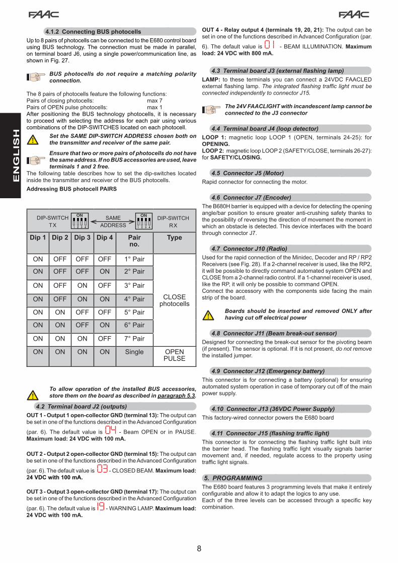
4.1.2 Connecting BUS photocellsUp to 8 pairs of photocells can be connected to the E680 control board usingBUS technology.The connectionmust bemade in parallel,onterminalboardJ6,usingasinglepower/communicationline,asshowninFig.27.
BUS photocells do not require a matching polarity connection.
The8pairsofphotocellsfeaturethefollowingfunctions:Pairsofclosingphotocells: max7PairsofOPENpulsephotocells: max1After positioning theBUS technology photocells, it is necessarytoproceedwith selecting theaddress foreachpair using variouscombinations of the DIP-SWITCHES located on each photocell.
Set the SAME DIP-SWITCH ADDRESS chosen both on the transmitter and receiver of the same pair.
Ensure that two or more pairs of photocells do not have the same address. If no BUS accessories are used, leave terminals 1 and 2 free.
The following tabledescribeshow toset thedip-switches locatedinside the transmitter and receiver of the BUS photocells.Addressing BUS photocell PAIRS
To allow operation of the installed BUS accessories, store them on the board as described in paragraph 5.3.
4.2 Terminal board J2 (outputs)OUT 1 - Output 1 open-collector GND (terminal 13):TheoutputcanbesetinoneofthefunctionsdescribedintheAdvancedConfiguration
(par. 6).The default value is04 - Beam OPEN or in PAUSE. Maximum load: 24 VDC with 100 mA.
OUT 2 - Output 2 open-collector GND (terminal 15):TheoutputcanbesetinoneofthefunctionsdescribedintheAdvancedConfiguration
(par.6).Thedefaultvalueis03 - CLOSED BEAM. Maximum load: 24 VDC with 100 mA.
OUT 3 - Output 3 open-collector GND (terminal 17): TheoutputcanbesetinoneofthefunctionsdescribedintheAdvancedConfiguration
(par.6).Thedefaultvalueis19 -WARNINGLAMP.Maximum load: 24 VDC with 100 mA.
OUT 4 - Relay output 4 (terminals 19, 20, 21): TheoutputcanbesetinoneofthefunctionsdescribedinAdvancedConfiguration(par.
6).Thedefault value is0 1 - BEAM ILLUMINATION. Maximum load: 24 VDC with 800 mA.
4.3 Terminal board J3 (external flashing lamp)LAMP: to these terminals you can connect a 24VDCFAACLEDexternalflashinglamp.The integrated flashing traffic light must be connected independently to connector J15.
The 24V FAACLIGHT with incandescent lamp cannot be connected to the J3 connector
4.4 Terminal board J4 (loop detector)LOOP 1: magnetic loop LOOP 1 (OPEN, terminals 24-25): for OPENING.LOOP 2: magneticloopLOOP2(SAFETY/CLOSE,terminals26-27):for SAFETY/CLOSING.
4.5 Connector J5 (Motor)Rapidconnectorforconnectingthemotor.
4.6 Connector J7 (Encoder)TheB680Hbarrierisequippedwithadevicefordetectingtheopeningangle/barpositiontoensuregreateranti-crushingsafety thankstothepossibilityofreversingthedirectionofmovementthemomentinwhich an obstacle is detected. This device interfaces with the board throughconnectorJ7.
4.7 Connector J10 (Radio)UsedfortherapidconnectionoftheMinidec,DecoderandRP/RP2Receivers(seeFig.28).Ifa2-channelreceiverisused,liketheRP2,itwillbepossibletodirectlycommandautomatedsystemOPENandCLOSEfroma2-channelradiocontrol.Ifa1-channelreceiverisused,liketheRP,itwillonlybepossibletocommandOPEN.Connect theaccessorywith thecomponentsside facing themainstrip of the board.
Boards should be inserted and removed ONLY after having cut off electrical power
4.8 Connector J11 (Beam break-out sensor)Designedforconnectingthebreak-outsensorforthepivotingbeam(ifpresent).Thesensorisoptional.Ifitisnotpresent,do not removetheinstalledjumper.
4.9 Connector J12 (Emergency battery)This connector is for connecting a battery (optional) for ensuringautomatedsystemoperationincaseoftemporarycutoffofthemainpowersupply.
4.10 Connector J13 (36VDC Power Supply)Thisfactory-wiredconnectorpowerstheE680board
4.11 Connector J15 (flashing traffic light)This connector is for connecting the flashing traffic light built intothe barrier head.The flashing traffic light visually signals barriermovement and, if needed, regulate access to the property usingtrafficlightsignals.
5. PROGRAMMINGTheE680boardfeatures3programminglevelsthatmakeitentirelyconfigurableandallowittoadaptthelogicstoanyuse.Eachof the three levels canbeaccessed througha specific keycombination.
9
EN
GL
ISH
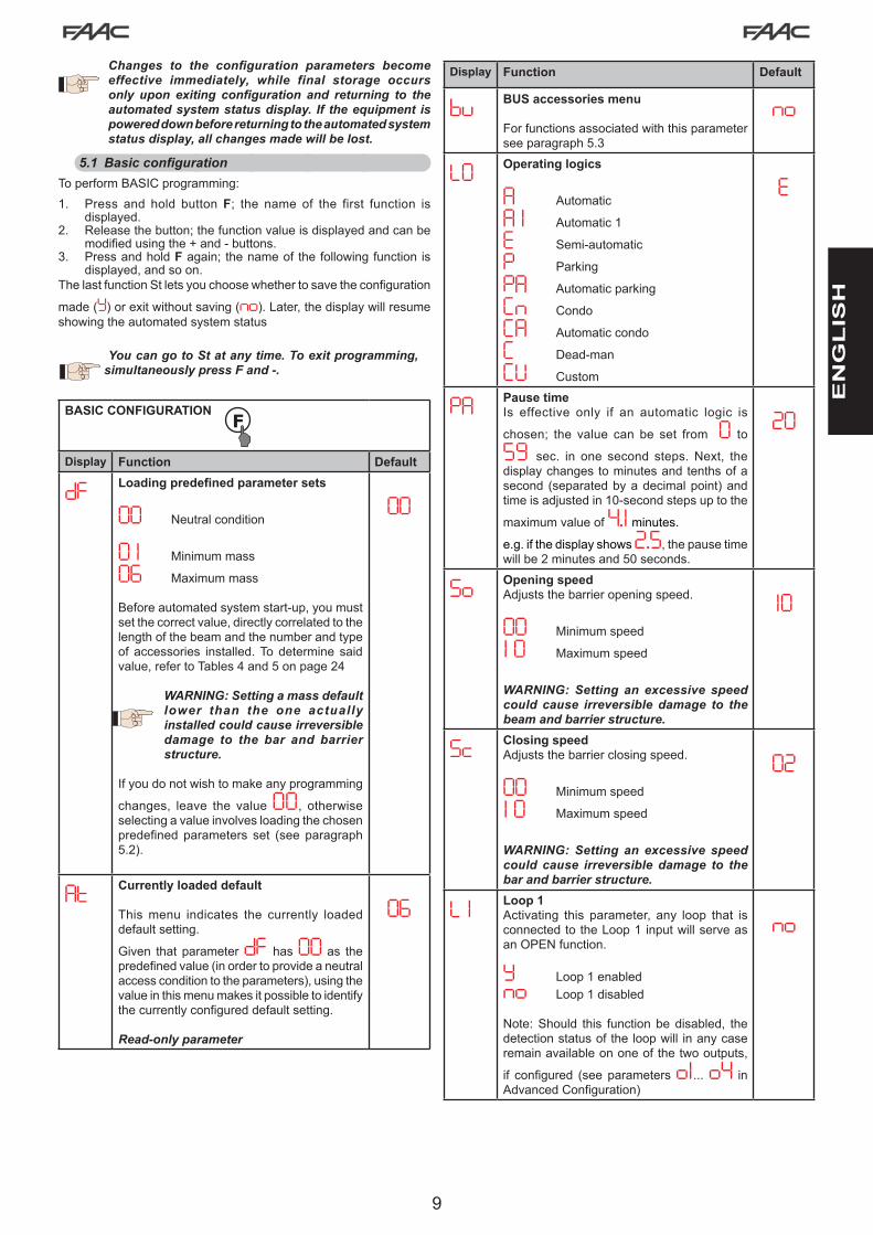
Changes to the configuration parameters become effective immediately, while final storage occurs only upon exiting configuration and returning to the automated system status display. If the equipment is powered down before returning to the automated system status display, all changes made will be lost.
5.1 Basic configurationToperformBASICprogramming:1. Press and hold buttonF; the name of the first function is
displayed.2. Releasethebutton;thefunctionvalueisdisplayedandcanbe
modifiedusingthe+and-buttons.3. Press and hold Fagain;thenameofthefollowingfunctionis
displayed,andsoon.ThelastfunctionStletsyouchoosewhethertosavetheconfiguration
made(Y)orexitwithoutsaving(no).Later,thedisplaywillresumeshowingtheautomatedsystemstatus
You can go to St at any time. To exit programming, simultaneously press F and -.
BASIC CONFIGURATION
Display Function Default
dF Loading predefined parameter sets
00 Neutralcondition
0 1 Minimummass
06 Maximummass
Beforeautomatedsystemstart-up,youmustsetthecorrectvalue,directlycorrelatedtothelengthofthebeamandthenumberandtypeof accessories installed. To determine said value,refertoTables4and5onpage24
WARNING: Setting a mass default lower than the one actually installed could cause irreversible damage to the bar and barrier structure.
Ifyoudonotwishtomakeanyprogramming
changes, leave the value00, otherwiseselectingavalueinvolvesloadingthechosenpredefined parameters set (see paragraph5.2).
00
At Currently loaded default
Thismenu indicates the currently loadeddefaultsetting.
Given that parameter dF has 00 as the predefinedvalue(inordertoprovideaneutralaccessconditiontotheparameters),usingthevalueinthismenumakesitpossibletoidentifythecurrentlyconfigureddefaultsetting.
Read-only parameter
06
Display Function Default
bu BUS accessories menu
Forfunctionsassociatedwiththisparameterseeparagraph5.3
no
LO Operating logics
A Automatic
A 1 Automatic1
E Semi-automatic
P Parking
PA Automaticparking
Cn Condo
CA Automaticcondo
C Dead-man
CU Custom
E
PA Pause timeIs effective only if an automatic logic is
chosen; the value can be set from O to
59 sec. in one second steps.Next, thedisplaychangestominutesandtenthsofasecond (separatedbyadecimalpoint)andtimeisadjustedin10-secondstepsuptothe
maximumvalueof4.1minutes.e.g.ifthedisplayshows2.5,thepausetimewillbe2minutesand50seconds.
20
So Opening speedAdjuststhebarrieropeningspeed.
00 Minimumspeed
1 0 Maximumspeed
WARNING: Setting an excessive speed could cause irreversible damage to the beam and barrier structure.
10
Sc Closing speedAdjuststhebarrierclosingspeed.
00 Minimumspeed
1 0 Maximumspeed
WARNING: Setting an excessive speed could cause irreversible damage to the bar and barrier structure.
02
L 1 Loop 1Activating this parameter, any loop that isconnectedtotheLoop1inputwillserveasanOPENfunction.
Y Loop 1 enabledno Loop 1 disabled
Note:Should this functionbedisabled, thedetectionstatusoftheloopwill inanycaseremainavailableononeofthetwooutputs,
if configured (seeparameterso1... o4 in AdvancedConfiguration)
no

10
EN
GL
ISH
Display Function Default
L2 Loop 2Activating this parameter, any loop that isconnectedtotheLoop2inputwillserveasaSAFETY/CLOSEfunction.
Y Loop 2 enabledno Loop 2 disabled
(see note regarding Loop 1)
no
S 1 Loop 1 sensitivityAdjuststhesensitivityofthevehicledetectionloop
00 Minimumsensitivity1 0 Maximumsensitivity
05
S2 Loop 2 sensitivityAdjuststhesensitivityofthevehicledetectionloop
00 Minimumsensitivity1 0 Maximumsensitivity
05
Mt Motor movement
Usingthefunctionprovidedbythispara-metermakesitpossibletomanuallymovethebarrierbar,operatingasdead-man. Pressing+willopentheautomatedsystem,pressing-causestheautomatedsystemtoclose.
oP pressing+,open
cL pressing -,close
--
St AUTOMATED SYSTEM STATUS:Thisallowsyoutochoosewhethertoquittheprogrammeand save the data. Y=quitandsavethedata no=quitwithoutsavingthedataOnquittingtheprogramme,presstheFkeytodisplaythestatusoftheautomatedsystem
00 Beam closed
0 1 Beam open
02 Stationaryreadytoopen
03 Stationaryreadytoclose
04 Automatedsystempaused
05 Opening
06 Closing
07 Failsafeinprogress
08 2-EASYdeviceverificationinprogress
09 Pre-flashingthenOPENS
10 Pre-flashingthenCLOSES
1 1 EMERGENCY Open
You can go to St at any time by simultaneously pressing F and -.
Displaying of the automated system status St is extremely important for the installing/maintenance technician in order to distinguish the logical processes that the board carries out during movement.
If, for example, the automated system status is CLOSED,
the display MUST read 00. When the OPEN command is
received, the display will change to 09, if pre-flashing is
enabled, or directly to 05 (the OPENING movement) to then
display 0 1 once the position of gate OPEN is reached).Exampleofastatussequencedisplayedstartingfromaclosedbarrier
00 Beam closed 05 Opening
0 1 Beam open /04 Pause 06 Closing
The sequence does not include statuses 09 and 10 which correspond to pre-flashing when opening and closing, respectively.
5.2 Changing the predefined parameters setTheE680boardfeaturessixsetsofpre-definedconfigurationsthatallowrapidadaptingtothesizeofthebeaminstalled,makingitthestartingpointforafineadjustmentoftheparameters.Toselectoneof the available configurations, youmust change the parameter
dF from the pre-set value00 (neutral condition) to the valuecorresponding to thebarrier configuration (beam length, typeandnumberofaccessories installed) shown inTables4or5onpage
24 (e.g.choosedefault04 forabeammeasuring5m in lengthwithfootandlights).
To complete configuration, it is necessary to exit the Basic
Configurationmenubypressing“F”untilparameterSt is reached orbypressing“F”and“-”

11
FSW-CL FSW-OPEN
Fig.3
EN
GL
ISH
This operation changes the value of the parameters So
and SC in Basic configuration and FO, FC, oc in Advanced configuration, setting them on the default values as shown in the tables in paragraph 6.3.
Unlike the other parameters, the value of step dF is not stored, thus allowing access to the menu through a neutral condition, which is the one displayed every time the configuration menu is opened..
Ifyoudonotwishtoloadanysetofpre-definedparameters,leave
parameter St on 00andpress“F”togoontothenextparameterSetting a set of pre-defined parameters that does not correspond to the actual configuration of the barrier could cause irreversible damage to the automated system, in particular if the default corresponds to a beam length shorter than the actual one.
5.3 BUS accessories menuThe E680 board is designed to connect up to 8 pairs of BUSphotocells.ForthebusdevicesconnectedtotheE680boardtobedetectedandmanagedbyit,theymustbestoredontheboard.Todothis,proceedasfollows:• cutoffpowerfromtheboard.• installandprogramtheaccessoriesusingthedesiredaddress,
depending on the function youwish to use (as described inparagraph4.1.2)
• poweruptheboard.• accessBasicConfiguration,asdescribedinparagraph5.1
• onceprogrammingstepbuisreached,no,willbedisplayed,indicatingthatherearenostoredbusdevices.
• to performentry, simultaneously press andhold the+ and -
buttonsforatleast5seconds(duringthistime,thewritingno will flash)
• oncetheprocedureiscompleted,Y will appear as confirmation.• when+and-arereleased,thedisplaywillshowthecurrentstatus
of theBUSdevices,ornoagain, if therearenoconnectedBUS devices.
Thefollowingimage(Fig.3)showsthecorrespondenceofthevariousdisplaysegmentstothedifferenttypesofBUSdevicesthatcanbeconnectedtothesystem:
FSW CL: BUS photocells placed to protect the gateclosingarea
OPEN: BUSphotocellsusedasOPENpulsegenerators
FromthedisplayofthestatusoftheBUSdevices,pressingthe+keyenablesthetypesofBUSdevicespresenttobeverified.Forexample,thefollowingphotographshowssafetydevicespresentduringclosingandapairofphotocellsfunctioningasopenpulse:
Fortheautomatedsystemtooperatecorrectly,thestatusofthesegmentsoftheleft-handdigitmustcorrespondto the automated system at rest andwithout pulsegeneratorsororsafetiesengaged.
WhentheCLOSEphotocellsareengaged,thebottomsegmentswillgoon,asshownintheimagetotheside.
If the pair of OPEN pulse generator photocells isengaged, the displaywill show the configuration ofsegmentsshownintheimageonthesideofthepage,inwhichthecorrespondingverticalsegmentison,andwillremainlikethisuntilthephotocellsaredisengaged.Ifinvolved,thepairofOPENpulsegeneratorphotocellscommands opening of the automated system andprevents it from closing until it is disengaged, like anormalOPENpulse received through terminal boardJ1(terminal3).
TheBUScommunicationsystemusesaself-diagnosticfunctionabletoprovideconnectionerrorsignalsorBUSaccessoriesconfigurationerrorsignal.
Thedisplaywillshowaflashingcc if there is a shortcircuitalongtheBUSline,asshowninthefigure.Tosolve theproblem it isnecessary tocarefullyverifyalltheconnectionsmade.
ThedisplaywillshowaflashingEr as shown in the imageon thesideof thepage,shouldmore than one pair of photocells have the sameadressandincaseofacallingorfailsafeerror.Ensurethatthesettingsarecorrect,withreferencetotheindicationsgiveninparagraph4.1.2
ThestatusoftheBUSandrelatedinputsignalscanalsobeseenbyanalysingthetwoLEDsDL1(red)andDL2(green),whichmakeitpossibletoimmediatelyverifyifBUScommunicationisactiveorifthereisanerror,andifthereareanyactiveinputsornot.ThestatusoftheLEDscanbeverifiedinthefollowingtables:
J6
DL1 DL2
2Easy BUS 21
Busstatus(alwayson)

12
EN
GL
ISH
DL1 LED description (Red)On Atleastoneoftheinputs(safeties,OPENpulse)is
engagedoractive
Off NoOPEN input isactiveandnosafetydevice isengaged
DL2 LED description (Green)On fixed
Normallyactive(LEDoneveniftherearenodevicesconnected)
Off BUS-2EASY line short-circuited (flash every 2.5sec.)
Rapid flashing
An error has been detected in the BUS-2EASY connection;repeattheacquisitionprocedure.Iftheerrorpersists,checkthat:• the system does not havemore than one
accessorywith the sameaddress (see alsoinstructionsregardingtheaccessories)
• makesurethereisnocallingerror(numberofdevicesconnectedisgreaterorlessthanthatstoredduringsetup)
6. Advanced ConfigurationToaccessAdvancedConfiguration, pressF and,while holding it,also press +:• when + isreleased,thenumberofthefirstavailablefunction
will appear• when F is also released, the value is displayed, and canbe
changedusing+ and -• pressingFagain,andholdingit,thenameofthenextparameter
will be displayed;when released, the value canbe changedusing+ and -
• oncethelastfunctionhasbeenreached,pressingF makes it possibletoeithersavethepreviouslychangedparametersorexitwithoutsavingthechanges;thedisplaywillgobacktoshowingthestatusoftheinputs.
ADVANCED CONFIGURATION
Display Function Default
FO Opening motor powerAdjuststhethrustofthemotorduringtheope-ningphase.
00 Minimumpower
50 Maximumpower
40
FC Closing motor powerAdjuststhethrustofthemotorduringtheclosingphase.
00 Minimumpower
50 Maximumpower
40
PF Pre-flashingThisparameterisusedtoactivatetheflashinglamp for 5 seconds before the selected movement.
no disabled
OC before each movement
CL beforeeachclosingmovement
OP beforeeachopeningmovement
PA onlyattheendofthepause
no
Display Function Default
tP Pre-flashing timePre-flashingtimeexpressedinseconds.
00 minimumpre-flashing
10 maximumpre-flashing
00
oc Sensitivity of obstacle during closing This determines the sensitivity to an obstaclebeforereversingtakesplace.
0 1 Minimumsensitivity
50 Maximumsensitivity
0 1
o 1 Output 1Settingthisfunctionmakesitpossibletomodifythe signal type of output 1, allowing highconnectionflexibilitywithexternaldevices.
00 Failsafe
0 1 TYPE 1 BEAM ILLUMINATION (outputactive when beam closed, disabledwith bar open or paused, intermittentwhenmoving).Use only with output 4!
02 DISABLED
03 Beam CLOSED
04 BeamOPENor inPAUSE, it goesoffduringclosingpre-flashing.
05 BeaminOPENINGMOVEMENT,includingpre-flashing.
06 BeaminCLOSINGMOVEMENT,includingpre-flashing.
07 Beam STATIONARY
08 Beam in EMERGENCY mode
09 LOOP1engaged
10 LOOP2engaged
1 1 OPEN for E680 slave
12 CLOSE for E680 slave
13 Beam RELEASED
14 Notused
15 Notused
16 FCAengaged
17 FCCengaged
18 Notused
19 WARNING LAMP (on during openingand pause, flashing when closing, offwhentheautomatedsystemisclosed)
04

13
EN
GL
ISH
Display Function Default
P 1 Output 1 PolarityAllowssettingoftheoutputpolarity:
Y outputNC
no outputNO
NOTE: iftheoutputsettingis00 (Failsafe),keepthevaluesettono
no
o2 Output 2Output2signaltype,see“Output 1” 03
P2 Output 2 PolarityOutput 2 polarity, see parameter regarding“Output 1 Polarity” no
o3 Output 3Output3signaltype,see“Output 1” 19
P3 Output 3 PolarityOutput 3 polarity, see parameter regarding“Output 1 Polarity” no
o4 Output 4Output4signaltype,see“Output 1” 0 1
P4 Output 4 PolarityOutput 4 polarity, see parameter regarding“Output 1 Polarity” no
o5 Integrated flashing lamp operating modeLetsyouchoosebetweentwooperatingmodesfor the integrated flashing lamp (if present)connectedtooutputJ15.
0 1 “Traffic light” mode (steady greenwhen paused/open, flashing red whenmoving,steadyredwhenclosed)
02 ”Flashing lamp” mode (flashing redwhen bar is moving, off in all othercases)
0 1
AS Service request (linked to the following two functions):If activated, at the end of the countdown(whichcanbesetwiththetwofollowing“CycleProgramming”functions)itactivatestheLAMPoutputfor4secevery30sec(servicerequest).It can be useful for setting programmedmaintenance work.
Y Activeno Disabled
no
nc Cycle programming in thousands:Is used to set a countdown of the systemoperation cycles; the value can be set from0 to 99 (thousands of cycles). The valuedisplayed is updated with the succession ofthe cycles, interacting with the value ofnC (99 decrements of nc correspond to 1 decrement of nC ).Thefunctioncanbeused, togetherwithnC ,toverifytheuseofthesystemandforuseof“ServiceRequest”.
00
Display Function Default
nC Cycle programming in hundreds of thousands:Is used to set a countdown of the systemoperationcycles; thevaluecanbesetfrom0to99 (hundredsof thousandsofcycles).Thevaluedisplayedisupdatedwiththesuccessionof the cycles, interacting with the value ofnc .(1decrementofnC corresponds to 99 decrements of nc ).The functioncanbeused, togetherwithnc ,toverifytheuseofthesystemandforuseof“ServiceRequest”.
0 1
St AUTOMATED SYSTEM STATUS:Thisallowsyoutochoosewhethertoquittheprogrammeand save the data. Y=quitandsavethedata no=quitwithoutsavingthedataOnquittingtheprogramme,presstheFkeytodisplay
againthestatusoftheautomatedsystem.You can go to St at any time by simultaneously pressing F and -
6.1 Configuring the loop detectorTheE680boardfeaturesanintegratedmetalmassdetectorfortheinductiondetectionofvehicles.
6.1.1 Specifications:• Galvanic separation between the detector electronics and the
loop electronics• Automatic alignment of the system immediately following
activation• Continuousresettingofthefrequencydrifts• Sensitivityindependentofloopinductivity• Adjustmentoftheloopworkfrequencywithautomaticselection• OccupiedloopmessagewithLEDdisplay• LoopstatusaddressableonoutputsOUT1,OUT2,OUT3and
OUT 46.1.2 Connection:
Connect the detection loops according to the layout on page 7,Fig.2
-Terminals24-25forLOOP1=loopwithgateopeningfunction;-Terminals26-27 forLOOP2= loopwithclosingand/orsafetywhenclosingfunction.
Formoreinformationontheeffectoftheloopsignalsontheautomatedsystem, refer to the logics tables in paragraph 10 “OPERATINGLOGICSTABLE”.To enable the functionality of the connected loops, enter BasicconfigurationmodeandsetparametersL1 and L2 on Yconsistentlywith thenumberand typeof connected loops. If onlyone loop isinstalled,enableonlythecorrespondingprogrammingstep.TheloopdetectoroperatingstatusisindicatedbytheDL3andDL4statusLEDs.

14
8 mm
30-5
0 m
m
~ 1 m
EN
GL
ISH
6.1.3 CalibrationEachtimetheE680boardispowered,theintegratedloopdetectorperformsacalibrationof theconnected loops.Therefore,youcanperformcalibrationbycuttingoffpowertotheboardforatleast10secondsandthenreconnectingit.From thebarrier statusdisplay, you canpress, at any time,+ to calibratetheloopconnectedtotheLOOP1inputor+ to calibrate theloopconnectedtotheLOOP2input.
CalibrationishighlightedbytheboarddiagnosticsbyflashingLEDsDL3andDL4,andwhencalibrationiscompleted,theywillindicatetheloopdetectionstatus,ifconnected.Theothersignalsprovidedbytheboarddiagnosticsaredescribedinthefollowingtable:
DL3
DL4
LOO
P 1
LOO
P 2
2 22 24 5 6 7
If one or both magnetic loops are not installed, the loop detector, following a first attempt to calibrate, will keep the status LEDs flashing every 5 seconds (as shown in the above table)
LED Status LOOP StatusOff Loop clear
On Loopengaged
Flashing(0.5s) Loop calibration inprogress
Rapidflashing Loopshortcircuit
Slowflashing(5s)
No loop orloopinterrupted
Twoflashes(every5s) Non-conforming loop(heater or inductanceoutofrange)
6.1.4 Adjusting sensitivityByadjustingthesensitivityoftheloopdetector,youdeterminethevariationofinductivity,foreachchannel,thatavehiclemustcauseinordertoactivatethecorrespondingdetectoroutput.Sensitivity is adjusted separately for each channel using the twoparameters S1 and S2inBasicconfiguration
6.1.5 Making the loopsTheloopmustbelaidatleast15cmfromfixedmetalobjects,atleast50cmfrommovingmetalobjectsandnomorethan5cmfromthesurfaceofthefinalpaving.Usea standardunipolar cablemeasuring1.5mm² indiameter (ifthe cable is laid belowground level directly, itmust havedoubleinsulation).MakeapreferablysquareorrectangularloopbypreparingaPVCcableductorbytracingthepaving,asshowninfigure16(thecornersmustbecutata45°angletoavoidcablebreaks).Laythecableusingthenumberofwindingsshowninthetable.Thetwoendsofthecablemustbetwistedtogether(atleast20timespermetre)fromthelooptotheE680board.Avoidsplicingacable(ifnecessary,weldtheconductorsandsealthespliceusingaheat-shrinkingsheath)and keep it separate from the mains power lines.
Loop Perimeter
Nr. of Windings
less than 3 m 6
from 3 to 4 m 5
from 4 to 6 m 4
from 6 to 12 m 3
more than 12 m 2
6.2 Expert ConfigurationEXPERTconfigurationisusedonlyintheeventthatoperationlogicscustomisationisalreadystored.
Before making changes at this level, be certain that the steps you wish to change and their effect on the automated system are fully understood.
Changing the third-level parameters involves indicating the CU value on the LO parameter of the first-level programming
ToaccessEXPERTconfiguration,press F and, holding it, press + for approximately 10 seconds.TheuseofF,+ and -inthismenuisthesameasintheothertwoprogramminglevels
“EXPERT” CONFIGURATION 10 sec
Display. Function Setting
0 1 Ifthisfunctionisactivated,automatic closingoccursafterthepausetime. Y=automaticclosingno = disabled
02 If this function is activated, two distinct input operationmode is obtained:OPEN foropeningandCLOSEDforclosing. Y=2-inputoperationno = disabled
03ActivationofrecognitionoftheOPEN and CLOSE input levels (maintained command). Thatistosay,theboardrecognisesthelevel(if,forexample,withOPENheld,youpress
STOP,whenthelatterisreleased,theautomatedsystemwillcontinuetoopen).If03 is
disabled theboardcommandsamanoeuvreonlyifthereisaninputvariation.
Y=levelrecognitionno=statusvariationrecognition

15
EN
GL
ISH
04 Activation of DEAD-MAN opening (command always pressed). Releasing the OPENcommand will stop operation Y = activeno = disabled
05Whenthisfunctionisactivated,theOPEN commandduringopeningwillstopmovement.
If parameter 06 is nothesystemisreadyforopening.If parameter 06 is Ythesystemisreadyforclosing.
Y=whenopeningitstopsno = disabled
06 Whenthisfunctionisactivated,theOPEN commandduringopeningreversesmovement.
If parameters 05 and 06 are noOPENwillhavenoeffectduringopening. Y=whenopeningitreversesno = disabled
07 Whenthisfunctionisactivated,theOPEN commandduringpausestopsoperation.
If parameters 07 and 08 are noOPENresetsthepausetime Y=wheninpauseitstopsno = disabled
08 Whenthisfunctionisactivated,theOPEN commandduringpausecausesclosing.
If parameters 07 and 08 are noOPENresetsthepausetime. Y =wheninpauseitclosesno = disabled
09 When this function is activated, the OPEN command during closing stops operation, otherwise it reverses movement. Y = stopsno = reverses
10 Activation of DEAD-MAN closing (command always pressed). Releasing the CLOSE command will stop operation Y = activeno = disabled
1 1 Whenthisfunctionisactivated,theCLOSE commandhaspriorityoverOPEN,otherwiseOPENhaspriorityoverCLOSE. Y = activeno = disabled
12 Whenthisfunctionisactivated,theCLOSE commandcommandsclosingwhenreleased.AslongasCLOSEisactivated,theunitstaysinclosingpre-flashing. Y = closes when releasedno=closesimmediately
13When this function isactivated, theCLOSE commandduringopeningstopsoperation,otherwisetheCLOSEcommandcommandsreverseimmediatelyorwhenopeningiscom-
pleted(seealsoparameter14)Y = CLOSE stopsno = CLOSE reverses
14 When this function is activated, and if parameter 13 is no, the CLOSE command commandsimmediateclosingattheendoftheopeningcycle(storesCLOSE).Ifparameters
13 and 14 are noCLOSEcommandsimmediateclosing.Y = closes at the end of openingno=immediateclosing
15 When this function is activated, with the system blocked by a STOP, a next OPEN
moves in the opposite direction. If parameter 15 is noitalwayscloses.Y = moves in the opposite directionno=alwayscloses
16 When this function isactivated,duringclosing, theCLOSING SAFETIES stop and allow motiontoresumewhentheyaredisengaged,otherwisetheyimmediatelyreverseopening. Y=closeswhendisengagedno = immediate reverse
17 Whenthisfunctionisactivated,theCLOSING SAFETIEScommandclosingwhentheyare
disengaged(seealsoparameter18).Y = closing when FSW
isdisengagedno = disabled
18 When this function is activated, and if parameter 17 is Y, the unit will wait for the opening cycle to end before executing the closing command provided by the CLOSING SAFETIES.
Y = closes at the end of openingno = disabled
19 Whenthisfunctionisactivated,duringclosing,LOOP2stopsandallowsmotiontoresumewhenitisdisengaged,otherwiseitimmediatelyreversesopening. Y=closeswhendisengagedno = immediate reverse
20 Whenthisfunctionisactivated,LOOP2commandsclosingwhenitisdisengaged(seealso
parameter 21). Y = closes if LOOP2 is clearno = disabled
2 1 Whenthisfunctionisactivated,andifparameter21 is Y,theunitwillwaitfortheopeningcycletoendbeforeexecutingtheclosingcommandprovidedbyLOOP2.
Y = closes at the end of openingno = disabled
22 When this function is activated: in case of a blackout, once electrical power has beenrestored,ifanOPENcommandisnotactivetheautomatedsystemreclosesimmediately.
Y = activeno = disabled
23LOOP 1commandsopeningand,oncecompleted,itclosesifdisengaged(usefulincaseofvehiclebacking-upwithconsecutiveloops).Ifdisabled,whenLOOP1isdisengaged,itdoes not close.
Y = closes if LOOP1 clearno = disabled
24 When this function is activated, an open or close command is only carried out after the safeties have been disengaged. Y = activeno = disabled
25A.D.M.A.P. functionWhenthisfunctionisactivated,theresultisoperationofsafeties compliant with French regulations.
Y = activeno = disabled

16
EN
GL
ISH
26 Whenthisfunctionisactivated,theCLOSING SAFETIESduringclosingstopandreversemovementwhentheyaredisengaged,otherwisetheyreverseimmediately.
Y = stops and reverses when disengaged.no=reversesimmediately.
27 DO NOT CHANGE no28 DO NOT CHANGE no29 DO NOT CHANGE no30 When this function is activated, theLOOP1 commands are prioritised rather than the
LOOP2 commands.Y = activeno = disabled
A0
HOLD CLOSE / HOLD OPEN functionWhenthisfunctionisactivated,theautomatedsystemwillmonitorthepositionofthebeam
at setintervals(seeparameterA 1 ).Ifthebeamisnotcompletelyclosedorcompletelyopen (dependingonthelogicalconditionoftheboard),theautomatedsystemwillcommandaCLOSEorOPENmovementtobringthebeambacktothecorrectposition,foramaximumof3seconds.If,whenthe3secondshaveelapsed,thebardoesnotgobacktocompletelyclosed/openposition(e.g.becausethebarisblocked),thefunctionwillbedisableduntilthenextOPENcommandisreceived.
Y
A 1HOLD CLOSE / HOLD OPEN function activation timeThis parameter indicates the time interval between two activations of the HOLD OPEN / HOLDCLOSEfunction,expressedinminutes.(from00 to 99)
60r 1 Loop 1 frequency reading
ThismenuitemletsyouverifythereadingofthecurrentoscillationfrequencyoftheloopconnectedtotheLoop1input.Theindicationshouldbereadasfollows:Firstdigit:tens(kHz)Seconddigit:units(kHz)Decimalpoint:hundreds(kHz)
Forexample,thereading05. referstoareadingof105kHz
Read-only parameter
r 2 Loop 2 frequency readingThismenuitemletsyouverifythereadingofthecurrentoscillationfrequencyoftheloop
connected to theLoop2 input. (seeparameter r1 forexplanationsonhowto read theindicatedvalue)
Read-only parameter
F 1 Loop 1 frequency selectionThisparameterletsyousetanoscillationfrequencyspecifictotheloopconnectedtotheLoop1input,orletsthesystemchoosethemostadequatesettingamongthe4available.
A Automaticselection
1-2-3-4 Frequency1-2-3-4
Note: When you exit theAdvanced configurationmenu after having changed the loopoperationfrequencysetting,thesystemwillberecalibrated.Thiswillprovideanupdatedfrequencyreadingonceyoure-enterthemenutoconsultthevaluesofparametersr1 or r2
A
F 2 Loop 2 frequency selectionThisparameterletsyousetanoscillationfrequencyspecifictotheloopconnectedtotheLoop2input,orletsthesystemchoosethemostadequatesettingamongthe4available.
A Automaticselection
1-2-3-4 Frequency1-2-3-4
Note: When you exit theAdvanced configurationmenu after having changed the loopoperationfrequencysetting,thesystemwillberecalibrated.Thiswillprovideanupdatedfrequencyreadingonceyoure-enterthemenutoconsultthevaluesofparametersr1 or r2
A

17
EN
GL
ISH
h 1 LOOP 1 holding timeIsusedtosetpresencetimeonloop1.Whenthistimehaselapsed,theboardwillself-calibrateandsignal“loopclear”(LEDDL3off).Whentheboardisturnedon,anautomaticresetiscarriedout.
Y 5minutes
no infinite
no
h2 LOOP 2 holding timeIsusedtosetpresencetimeonloop2.Whenthistimehaselapsed,theboardwillself-calibrateandsignal“loopclear”(LEDDL4off).Whentheboardisturnedon,anautomaticresetiscarriedout.
Y 5minutes
no infinite
no
H1 Loop 1 articulated lorry functionThisfunctionletsyouincreasethelevelofsensitivityatthetimeofdetection,toallowcorrectdetectionevenincaseofverytallvehiclesorduringthetransitofatractorandtrailer.
Y enabled
no disabled
Y
H2 Loop 2 articulated lorry functionThisfunctionletsyouincreasethelevelofsensitivityatthetimeofdetection,toallowcorrectdetectionevenincaseofverytallvehiclesorduringthetransitofatractorandtrailer.
Y enabled
no disabled
Y
t Work time (time-out)Maximumworktimeoftheautomatedsystembeforethemotorstops, if theopenorclose
positionisnotreached.ThevaluecanbesetfromO to 59sec.inonesecondsteps.Next,thedisplaychangestominutesandtenthsofasecond(separatedbyadecimalpoint)and
timeisadjustedin10-secondstepsuptothemaximumvalueof4.1minutes.
30
St STATUS OF THE AUTOMATED SYSTEM:Exitfromprogramming,storageofdataandautomatedsystemstatusdisplay.
6.3 Pre-Defined Parameter SetsThetablebelowshows,foreachsetofpre-definedparameters,thevaluesthattheywillloadintheboardmemory.
Basic Configuration
dF 0 1 0 2 0 3 0 4 0 5 0 6At 01 02 03 04 05 06buLO E E E E E EPA 20 20 20 20 20 20So 10 10 10 10 10 10Sc 10 05 05 04 02 02L 1 no no no no no noL2 no no no no no noS 1 05 05 05 05 05 05S2 05 05 05 05 05 05
Advanced ConfigurationThefollowingtableshows,foreachsetofpre-definedparameters,the values that theywill load in the boardmemory, in advancedconfiguration.
dF 0 1 02 03 04 05 06FO 25 25 30 28 30 40FC 25 25 30 28 30 40PF no no no no no notP 00 00 00 00 00 00oc 35 35 38 32 32 32FS no no no no no noo 1 00 00 00 00 00 00P 1 no no no no no noo2 03 03 03 03 03 03P2 no no no no no noo3 0 1 0 1 0 1 0 1 0 1 0 1P3 no no no no no noo4 02 02 02 02 02 02P4 no no no no no noo5 01 01 01 01 01 01AS no no no no no nonc 00 00 00 00 00 00nC 00 00 00 00 00 00
18
J6
J12
J13
J11 J14
J7
+ - F
Sw1 Sw2 Sw3J15
J1 J2 J3 J4
M1
DL1 DL2
DL1
0
DL1
1
DL1
2
DL1
3
DL1
4
DL1
8
DL1
7
DL7
DL5
DL8
DL6
DL9
DL1
6
DL3
DL4
DL15
2Eas
y BU
S
OPE
NCLO
SE
FSW
STO
PALA
RM
GN
D
+24
1 2 3 4 5 6 7 8 9 10 11 12 13 14 1516 17 18 19 20 21 22 23 18 19 20 21
+24
+24
+24
+24
OU
T1
OU
T2
OU
T3
Rel
ay N
ORel
ay N
CG
ND
LAM
P
LOO
P 1
LOO
P 2
BATTERY
ENCODERDISP1
Fig.4
EN
GL
ISH
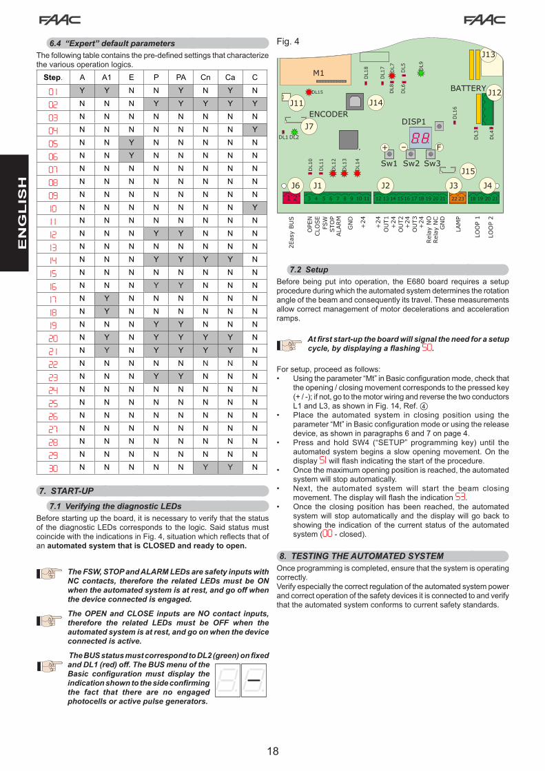
6.4 “Expert” default parametersThefollowingtablecontainsthepre-definedsettingsthatcharacterizethevariousoperationlogics.
Step. A A1 E P PA Cn Ca C
0 1 Y Y N N Y N Y N
02 N N N Y Y Y Y Y
03 N N N N N N N N
04 N N N N N N N Y
05 N N Y N N N N N
06 N N Y N N N N N
07 N N N N N N N N
08 N N N N N N N N
09 N N N N N N N N
10 N N N N N N N Y
1 1 N N N N N N N N
12 N N N Y Y N N N
13 N N N N N N N N
14 N N N Y Y Y Y N
15 N N N N N N N N
16 N N N Y Y N N N
17 N Y N N N N N N
18 N Y N N N N N N
19 N N N Y Y N N N
20 N Y N Y Y Y Y N
2 1 N Y N Y Y Y Y N
22 N N N N N N N N
23 N N N Y Y N N N
24 N N N N N N N N
25 N N N N N N N N
26 N N N N N N N N
27 N N N N N N N N
28 N N N N N N N N
29 N N N N N N N N
30 N N N N N Y Y N
7. START-UP7.1 Verifying the diagnostic LEDs
Beforestartinguptheboard,itisnecessarytoverifythatthestatusof thediagnosticLEDscorrespondsto the logic.SaidstatusmustcoincidewiththeindicationsinFig.4,situationwhichreflectsthatofan automated system that is CLOSED and ready to open.
The FSW, STOP and ALARM LEDs are safety inputs with NC contacts, therefore the related LEDs must be ON when the automated system is at rest, and go off when the device connected is engaged.
The OPEN and CLOSE inputs are NO contact inputs, therefore the related LEDs must be OFF when the automated system is at rest, and go on when the device connected is active.
The BUS status must correspond to DL2 (green) on fixed and DL1 (red) off. The BUS menu of the Basic configuration must display the indication shown to the side confirming the fact that there are no engaged photocells or active pulse generators.
7.2 SetupBeforebeingput intooperation, theE680board requiresa setupprocedureduringwhichtheautomatedsystemdeterminestherotationangleofthebeamandconsequentlyitstravel.Thesemeasurementsallowcorrectmanagementofmotordecelerationsandaccelerationramps.
At first start-up the board will signal the need for a setup cycle, by displaying a flashing S0.
Forsetup,proceedasfollows:• Usingtheparameter“Mt”inBasicconfigurationmode,checkthat
theopening/closingmovementcorrespondstothepressedkey(+/-);ifnot,gotothemotorwiringandreversethetwoconductorsL1andL3,asshowninFig.14,Ref.d
• Place the automated system in closing position using theparameter“Mt”inBasicconfigurationmodeorusingthereleasedevice,asshowninparagraphs6and7onpage4.
• Press and holdSW4 (“SETUP” programming key) until theautomatedsystembeginsaslowopeningmovement.On thedisplayS1willflashindicatingthestartoftheprocedure.
• Oncethemaximumopeningpositionisreached,theautomatedsystemwillstopautomatically.
• Next, the automated system will start the beam closingmovement.ThedisplaywillflashtheindicationS3.
• Once the closingposition hasbeen reached, the automatedsystemwillstopautomaticallyand thedisplaywillgoback toshowing the indicationof thecurrentstatusof theautomatedsystem(00 - closed).
8. TESTING THE AUTOMATED SYSTEMOnceprogrammingiscompleted,ensurethatthesystemisoperatingcorrectly.Verifyespeciallythecorrectregulationoftheautomatedsystempowerandcorrectoperationofthesafetydevicesitisconnectedtoandverifythattheautomatedsystemconformstocurrentsafetystandards.

19
1213
1415
1617
1819
2021
+24
+24
+24
+24
OUT1
OUT2
OUT3
GND
Relais
NOCOM
OPENCLOSEFSWSTOPALARMG
ND
+24
34
56
78
910
11 J2
J1
o2 = 11 P2 = noo3 = 12P3 = no
LO = CPA = 01
01 = Y03 = Y10 = Y
1213
1415
1617
1819
2021
+24
+24
+24
+24
OUT1
OUT2
OUT3
GND
Relais
NOCOM
OPENCLOSEFSWSTOPALARMG
ND
+24
34
56
78
910
11o1 = 18 P1 = no
1213
1415
1617
1819
2021
+24
+24
+24
+24
OUT1
OUT2
OUT3
GND
Relais
NOCOM
OPENCLOSEFSWSTOPALARMG
ND
+24
34
56
78
910
11
o1 = 18 P1 = no
EN
GL
ISH
9. MASTER/SLAVE CONFIGURATIONIftheinstallationcontemplatesthegateareabeingcoveredbytwoopposingbarriers,aMaster/Slaveconfigurationmaybeusedfortheboardswhichwill activate the twobarriers.This configurationpermitsconnectionofthecommandandsafetysignalstobesimplified(they are all connected to just one board), also ensuring perfectsynchronisationofthetwoautomatedsystems.
“MASTERdevice”meanstheboardtowhichallthepulsegeneratorsandsafetydevicesareconnected.“SLAVEdevice”meanstheboardwhichiscontrolledbytheMASTERthroughpulseinputs,whilethesafetyinputsarebypassed.
The electrical connections and the parameters needed for correct functioningofthesysteminaMaster/Slaveconfigurationareshowninthefollowingdiagram:
Master device
Slavedevice
10. INTERLOCKThe interlock function enables two in-line barriers to bemanaged (see fig.) so that opening of one is subordinated toclosing of the other. Operation can be one-way or two-way.
For in-line barriers, setOUT1 INTERLOCK to parameter 18 (see2ndLEVELPROG.)onbothboardsandconnectthemasinfigure.

20
EN
GL
ISH
LOGIC “A” PULSES
AUTOMATED SYSTEM STATUS OPEN A CLOSE STOP FSW LOOP 1 LOOP 2
CLOSEDopens and closes afterthepause
timeno effect no effect
(openinginhibited) no effectopens and closes afterthepause
timeno effect
WHEN OPENING no effectimmediately reverses to closing
blocksoperation no effect no effect no effect
OPEN IN PAUSE resets pausetime closes blocks
operationresetspause
time(closinginhibited)
resets pausetime
resetspausetime
(closinginhibited)
WHEN CLOSINGimmediately reverses to opening
no effect blocksoperation
immediatelyreverses to opening
immediately reverses to opening
immediatelyreverses to opening
BLOCKED closes closesno effect
(openingandclosinginhibited)
no effect (closinginhibited)
opens and closes afterthepause
timeno effect
(closinginhibited)
LOGIC “A1” PULSES
AUTOMATED SYSTEM STATUS OPEN A CLOSE STOP FSW LOOP 1 LOOP 2
CLOSEDopens and closes afterthepause
timeno effect no effect
(openinginhibited) no effectopens and closes afterthepause
timeno effect
WHEN OPENING no effectimmediately reverses to closing
blocksoperation
closes immediately
afteropeningiscompleted
no effectcloses
immediatelyafteropeningis
completed
OPEN IN PAUSE resets pausetime closes blocks
operation closes resets pausetime
closes when disengaged
WHEN CLOSINGimmediately reverses to opening
no effect blocksoperation
immediatelyreverses to opening
immediately reverses to
opening,closesattheendofpause
immediatelyreverses to
opening,closesagainonceopening
is completed
BLOCKED closes closesno effect
(openingandclosinginhibited)
inhibitsclosingopens and closes afterthepause
time
no effect (closing
inhibited)
Inbrackets,theeffectsontheotherinputswhenthepulseisactive
LOGIC “E” PULSESAUTOMATED
SYSTEM STATUS OPEN A CLOSE STOP FSW LOOP 1 LOOP 2
CLOSED opens no effect no effect (openinginhibited) no effect opens no effect
WHEN OPENING blocksoperation
immediately reverses to closing
blocksoperation no effect no effect no effect
OPEN closes closes no effect (closinginhibited)
no effect (closinginhibited) no effect no effect
(closinginhibited)
WHEN CLOSINGimmediately reverses to opening
no effect blocksoperation
immediatelyreverses to opening
immediately reverses to opening
immediatelyreverses to opening
BLOCKED closes closesno effect
(openingandclosinginhibited)
no effect (closinginhibited) opens no effect
(closinginhibited)
11. OPERATING LOGICS TABLE
Tab. 1/c
Tab. 1/b
Tab. 1/a

21
EN
GL
ISH
Inbrackets,theeffectsontheotherinputswhenthepulseisactive
LOGIC “P” PULSESAUTOMATED
SYSTEM STATUS OPEN A CLOSE STOP FSW LOOP 1 LOOP 2
CLOSED opens no effect no effect (openinginhibited) no effect
opens and once openingis
completed closes if disengaged
no effect
WHEN OPENING no effectcloses
immediatelyafteropeningis completed
blocksoperation no effect no effect
closes immediately
afteropeningiscompleted
OPEN no effect(closinginhibited) closes no effect
(closinginhibited)no effect
(closinginhibited) preventsclosing closes when disengaged
WHEN CLOSINGimmediately reverses to opening
no effect blocksoperation
blocks and when disengaged continuesto
close
immediately reversestoopening,andonceopeningiscompleted closes if
disengaged
blocks and when disengaged continuesto
close
BLOCKED opens closesno effect
(openingandclosinginhibited)
no effect(closinginhibited)
opens and once openingis
completed closes if disengaged
no effect (closinginhibited)
LOGIC “PA” PULSESAUTOMATED
SYSTEM STATUS OPEN A CLOSE STOP FSW LOOP 1 LOOP 2
CLOSEDopens and closes afterthepause
timeno effect no effect
(openinginhibited) no effectopens and once
openingis completed closes if
disengagedno effect
WHEN OPENING no effectcloses
immediatelyafteropeningis
completed
blocksoperation no effect no effect
closes immediately
afteropeningiscompleted
OPEN IN PAUSE resetspausetime closes blocksoperation
resetspausetime
(closinginhibited)resetspausetime closes when
disengaged
WHEN CLOSINGimmediately reverses to opening
no effect blocksoperation
blocks and when disengaged continuesto
close
immediately reversestoopening,andonceopeningiscompleted closes if if
disengaged
blocks and when disengaged continuesto
close
BLOCKEDopens and closes afterthepause
timecloses
no effect (openingand
closinginhibited)no effect
(closinginhibited)
opens and once openingis
completed closes if disengaged
no effect (closinginhibited)
LOGIC “Cn” PULSESAUTOMATED
SYSTEM STATUS OPEN A CLOSE STOP FSW LOOP 1 LOOP 2
CLOSED opens no effect no effect (openinginhibited) no effect opens no effect
WHEN OPENING no effectcloses
immediatelyafteropeningis
completed
blocksoperation no effect no effect
closes immediately
afteropeningiscompleted
OPEN no effect(closinginhibited) closes no effect
(closinginhibited)no effect
(closinginhibited) no effect closes when disengaged
WHEN CLOSINGimmediately reverses to opening
no effect blocksoperation
reverses to openingand closes after pausetime
immediately reverses to opening
immediatelyreverses to opening
BLOCKED opens closesno effect
(openingandclosinginhibited)
no effect (closinginhibited) opens no effect
(closinginhibited)
Tab. 1/e
Tab. 1/d
Tab. 1/f

22
EN
GL
ISH
Inbrackets,theeffectsontheotherinputswhenthepulseisactive
LOGIC “CA” PULSESAUTOMATED
SYSTEM STATUS OPEN A CLOSE STOP FSW LOOP 1 LOOP 2
CLOSEDopens and closes afterthepause
timeno effect no effect
(openinginhibited) no effectopens and closes afterthepause
timeno effect
WHEN OPENING no effectcloses
immediatelyafteropeningis
completed
blocksoperation no effect no effect
closes immediately
afteropeningiscompleted
OPEN IN PAUSE resetspausetime closes blocksoperation
resetspausetime
(closinginhibited)resetspausetime closes when
disengaged
WHEN CLOSINGimmediately reverses to opening
no effect blocksoperation
reverses to openingandclo-sesafterpause
time
immediately reverses to opening
immediatelyreverses to opening
BLOCKEDopens and closes afterthepause
timecloses
no effect (openingand
closinginhibited)no effect
(closinginhibited)opens and closes afterthepause
timeno effect
(closinginhibited)
LOGIC “C” MAINTAINED COMMANDS PULSESAUTOMATED
SYSTEM STATUS OPEN A CLOSE STOP FSW LOOP 1 LOOP 2
CLOSED opens no effect no effect (openinginhibited) no effect no effect no effect
WHEN OPENING / no effect blocksoperation no effect no effect no effect
OPEN no effect(closinginhibited) closes blocks
operation no effect no effect(closinginhibited)
no effect(closinginhibited)
WHEN CLOSINGimmediately reverses to opening
/ blocksoperation
blocksoperation
blocksoperation
blocksoperation
BLOCKED opens closesno effect
(openingandclosinginhibited)
no effect (closinginhibited)
no effect(closinginhibited)
no effect(closinginhibited)
Tab. 1/g
Tab. 1/h

23
EN
GL
ISH
Bar length
Installed accessories
2 m 2,5 m 3 m 3,5 m 4m 4 m (withcoupling) 4,5 m 5 m 5 m (with
coupling)
No accessories 1 2 3 4 4 5 6 6 6
Lights 1 2 3 4 4 5 6 6
Lights / Skirt 1 2 4 5 6 6 6Lights / Foot /
Skirt 2 3 4 6 6 6 6
Lights / Foot 2 3 3 5 6 6 6
Foot 1 2 3 5 6 6 6
Skirt 1 2 3 4 6 6 6
Skirt/Foot 2 3 4 5 6 6 6
Table 2
Bar length
Installed accessories
5 m (withoutcoupling)
5 m 5,5 m 6 m 6,5 m 7 m 7,5 m 8 m
No accessories 2 2 3 3 4 4 4 5
Lights 2 2 3 3 4 4 5 6
Lights / Skirt 2 3 3 4 4 5 6
Lights / Foot / Skirt 3 3 4 4 5 6
Lights / Foot 2 3 3 4 4 5 6 6
Foot 2 3 3 4 4 4 5 6
Skirt 2 3 3 4 4 5 6
Skirt/Foot 3 3 3 4 4 5
Table 3
12. BALANCING TABLESThefollowingtwotablesindicatethefixingpositionofthepistonsontherockerarminrelationtothelengthofthebeamandthepresenceofaccessoriessecuredtoit,ifany.Table2referstothebalancespringforbarlengthsequaltoorshorterthan5mandfeaturingaprofilecorrespondingtotheoneinFig.8onpage25,ref.a(“S”profile).Table3referstothebalancespringforbarlengthsequaltoorlongerthan5mandfeaturingaprofilecorrespondingtotheoneinFig.8onpage25,ref.b(“L”profile).Figure30containsthekeyforidentifyingthefixingholesbasedonthenumberindicatedinthetables.

24
EN
GL
ISH
Bar length
Installed accessories
2 m 2,5 m 3 m 3,5 m 4m 4 m (withcoupling) 4,5 m 5 m 5 m (with
coupling)
No accessories 1 1 2 2 2 3 3 3 3
Lights 1 1 2 2 2 3 3 3
Lights / Skirt 1 1 2 3 3 3 3Lights / Foot /
Skirt 1 2 2 3 3 3 3
Lights / Foot 1 2 2 3 3 3 3
Foot 1 1 2 3 3 3 3
Skirt 1 1 2 2 3 3 3
Skirt/Foot 1 2 2 3 3 3 3
Table 4
Bar length
Installed accessories
5 m (withoutcoupling)
5 m 5,5 m 6 m 6,5 m 7 m 7,5 m 8 m
No accessories 4 4 5 5 5 5 5 6
Lights 4 4 5 5 5 5 6 6
Lights / Skirt 4 5 5 6 6 6 6
Lights / Foot / Skirt 5 5 5 5 6 6
Lights / Foot 4 5 5 5 5 6 6 6
Foot 4 5 5 5 5 5 6 6
Skirt 4 5 5 5 5 6 6
Skirt/Foot 5 5 5 5 5 6
Table 5
13. DEFAULT SELECTION TABLES (dF parameter)Thepurposeofthetwofollowingtablesistodetermine,dependingonthelengthofthebarandthenumberandtypeofaccessoriesinstalled,thecorrectdefaultvaluetosetinthefirstBasicprogrammingfunction.Table4referstothebalancespringforbarlengthsequaltoorshorterthan5mandfeaturingaprofilecorrespondingtotheoneinFig.8onpage25,ref.a(“S”profile).Table5referstothebalancespringforbarlengthsequaltoorlongerthan5mandfeaturingaprofilecorrespondingtotheoneinFig.8onpage25,ref.b(“L”profile).ThekeytosymbolsforidentifyingthefixingholesbasedonthenumberindicatedinthetablesisshowninFig.30.
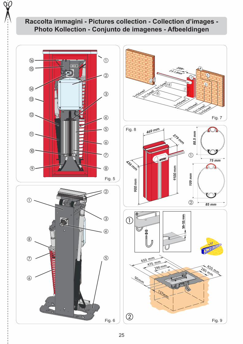
25
20÷2
2m
m
a
20÷2
2m
m
b
a
b
c
d
e
f
g
hi
j
k
l
m
5
2 x 0,5 mm2
3 x 0,5 mm2
2 x 0,5 mm2
2 x 1,5 mm2
3 x 0,5 mm2
2 x 1,5 mm22 x 1,5 mm2
3 X 1,5mm 2
230V~
6
6
23
4
2
1
1100
mm
900
mm
469 mm
436 mm
279 mm
Fig. 5
Raccolta immagini - Pictures collection - Collection d’images - Photo Kollection - Conjunto de imagenes - Afbeeldingen
88.5
mm
75 mm
450 mm
650 mm
280 mm
470 mm
290 mm
90mm
= =
137mm
Fig. 6
Fig. 7
Fig. 8
Fig. 9
n
o
p
a
b
c
d
e
f
g
h
109
mm
85 mm
a
b

26
a b
DX SX
a
b c
Fig. 10
Fig. 11
M ML1
L2
L3 L1
L2
L3
Fig. 12
d
Fig. 13
Fig. 14
Fig. 15
a
b
Fig. 16
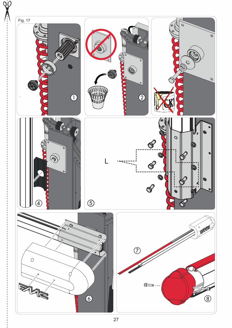
27
a b c
d e
f
g
h
Fig. 17
L

28
Fig. 18
a
b
a b
d
Fig. 19
c
1
2
Fig. 20

29
a
b
Fig. 21
d
e
f
c

30
a
b
Fig. 26
J1
+24
GND
+24
GND
OPE
NCLO
SE
FSW
STO
PALA
RM
GND +24
3 4 5 6 7 8 9 10 11
SAFE
TX CLRX CL
1
2
5
4
3
1
2
J1
+24
+24
GND
OPE
NCLO
SE
FSW
STO
PALA
RM
GND +24
3 4 5 6 7 8 9 10 11
SAFE
TX CLRX CL
1
2
5
4
3
1
2
12 13 14 1516 17 18 19 20 21
+24
+24
+24
+24
OU
T1
OU
T2
OU
T3
GN
D
Relais
NO
CO
M
J2
Fig. 24
J1
+24
GND
+24
GND
OPE
NCLO
SE
FSW
STO
PALA
RM
GND +24
3 4 5 6 7 8 9 10 11
SAFE
TX CLRX CL
1
2
5
4
3
1
2
TX CL RX CL
1
2
5
4
3
1
2
+24
GND
+24
GND
Fig. 22
Fig. 23
Fig. 25
J1
OPEN
CLO
SE
FSW
STO
PALA
RM
GND +24
3 4 5 6 7 8 9 10 11

31
DS1
DL1
DL2BUS BUS
RX - TX
DL2
DS1ONON
BUS BUS
DS1
DL1
DL2BUS BUS
DL2
DS1ONON
BUS BUS
2EASY
12
J6
Fig. 28 Fig. 27
Fig. 29
e
Fig. 30
a b c df

32
Fig. 31
a b
c
d e

33
Fig. 32
f
g


B680H
Guida per l’utenteUser's guide
Instructions pour l’utilisateurAnleitungen für den Benutzer
Guía para el usuarioGebruikersgids

2
MANUALE UTENTE AUTOMAZIONE B680H1. AVVERTENZE
1) FAAC declina qualsiasi responsabilità derivata dall’uso improprio o diverso da quello per cui l’automatismo è destinato.
2) FAAC non è responsabile dell’inosservanza della Buona Tecnica nella costru-zione delle chiusure da motorizzare, nonché delle deformazioni che dovessero intervenire nell’utilizzo.
3) L’automazione dispone di una sicurezza intrinseca antischiacciamento costituita da un controllo di coppia.
4) FAACdeclinaogniresponsabilitàaifinidellasicurezzaedelbuonfunzionamentodell’automazione, in caso vengano utilizzati componenti dell’impianto non di produzione FAAC.
5) Per la manutenzione utilizzare esclusivamente parti originali FAAC. 6) Noneseguirealcunamodificasuicomponentifacentipartedelsistemad’auto-
mazione. 7) L’installatore deve fornire tutte le informazioni relative al funzionamento ma-
nuale del sistema in caso di emergenza e consegnare all’Utente utilizzatore dell’impianto il libretto d’avvertenze allegato al prodotto.
8) Non permettere ai bambini o persone di sostare nelle vicinanze del prodotto durante il funzionamento.
9) Tenere fuori dalla portata dei bambini radiocomandi o qualsiasi altro datore di impulso, per evitare che l’automazione possa essere azionata involontariamente.
10) Il transito deve avvenire solo ad automazione ferma. 11) L’Utente utilizzatore deve astenersi da qualsiasi tentativo di riparazione o
d’interventodirettoerivolgersisoloapersonalequalificato.12) Manutenzione:effettuarealmenosemestralmentelaverificafunzionaledell’im-
pianto, con particolare attenzione all’efficienza dei dispositivi di sicurezza(compresa, ove previsto, la forza di spinta dell’operatore) e di sblocco.
2. DESCRIZIONEL’automazione è costituita da una sbarra in alluminio bianca con adesivi rifrangenti, luci di segnalazione opzionali, un cofano di copertura ed un montante in acciaio. All’interno del cofano risiede l’operatore composto dalmontantealqualesonofissatiunacentralinaoleodinamicaeduepistoni tuffanti che per mezzo di un bilancere provvedono alla rotazione della sbarra. Quest’ultima rimane in equilibrio grazie a una molla di bilanciamento assemblata su uno dei pistoni tuffanti. L’apparecchiatura elettronica di comando è anch’essa alloggiata sul montante all’interno di un contenitore, ed il tutto è protetto dal cofano esterno di copertura.Il sistema è dotato di sicurezza antischiacciamento elettronica regola-bile, di un dispositivo che garantisce arresto e blocco della sbarra in qualsiasi posizione e di un comodo sblocco manuale da manovrare in caso di black-out o disservizio.
3. FUNZIONAMENTO MANUALENel caso in cui sia necessario azionare manualmente la barriera a causa della mancanza di alimentazione elettrica o disservizio dell’au-tomazione, è necessario agire sul dispositivo di sblocco tramite la chiave in dotazione.La chiave di sblocco in dotazione può essere triangolare (Fig. 18 rif. a ) o personalizzata (Fig. 18 rif. b opzionale).• Inserire la chiave di sblocco nella serratura e ruotare la chiave in
senso antiorariofinoabattuta,comeinFig.18 • Effettuare manualmente la manovra di apertura o chiusura della
sbarra.
Con asta sbloccata, il motore si potrebbe attivare per circa 3 secondi. Tale funzionamento è normale e previsto dal parametro Hold Close / Hold Open
4. RIPRISTINO DEL FUNZIONAMENTO NORMALEPer evitare che un impulso involontario possa azionare la barriera durante la manovra , prima di inserire il sistema di blocco, togliere alimentazione all’impianto.
chiave di sblocco triangolare (standard):- ruotare la chiave in senso orario finoall’arrestoedestrarla(Fig.18
rif a).chiave di sblocco personalizzata (opzionale): - ruotare la chiave in senso orario finoall’arrestoedestrarla.(Fig.18
rif. b).
B680H AUTOMATION USER MANUAL1. WARNINGS
1) FAAC declines all liability caused by improper use or use other than that for which the automated system was intended.
2) FAAC is not responsible for failure to observe Good Technique in the construc-tion of the closing elements to be motorised, or for any deformation that may occur during use.
3) The automated system features a built-in anti-crushing safety device consisting of a torque control.
4) FAACdeclinesall liabilityasconcernssafetyandefficientoperationof theautomated system, if system components not produced by FAAC are used.
5) For maintenance, strictly use original parts by FAAC. 6) Do not in any way modify the components of the automated system 7) The installer shall supply all information concerning manual operation of the
systemincaseofanemergency,andshallhandovertotheUsertheleafletsupplied with the product.
8) Do not allow children or adults to stay near the product while it is operating. 9) Keep radio controls or other pulse generators away from children, to prevent
the automated system from being activated involuntarily. 10) Transiting is permitted only when the automated system is stationary. 11) The User must not attempt any kind of repair or direct action whatever and
contactqualifiedpersonnelonly.12) Maintenance: check at least every 6months the efficiency of the system,
particularlytheefficiencyofthesafetydevices(including,whereforeseen,theoperator thrust force) and of the release devices.
2. DESCRIPTIONThe automated system consists of a white aluminium beam with reflectors,optionalsignallinglights,acoveringcompartmentandsteeluprightprofile.Insidethecompartmentthereisanoperatorconsistingoftheuprightprofilewithahydraulicunitandtwoplungingpistonsfixedtoit,which,bymeansofarockerarm,rotatethebeam.Thelatterremainsbalancedthankstoabalancespringfittedononeofthetwo plunging pistons. The electronic control equipment is also housed on the upright, inside a compartment, and the whole is protected by theexternalcoveringcompartment.The system features an adjustable electronic anti-crushing safety, a device that guarantees stopping and locking of the beam in any position, and a convenient manual release for use in case of black-outorinefficiency.
3. MANUAL OPERATIONShould manual operation of the barrier be required due to electrical power cut-offs or automated system inefficiency, use the releasedevice with the provided key.The provided unlocking key is either triangular (Fig. 18 ref. a ) or customised (Fig. 18 ref. b optional).• Insert the unlocking key in the lock and turn the key anticlockwise
until it clicks into place, as shown in Fig. 18• Open or close the beam manually.
With the bar released, the motor may start for approximately 3 seconds. This is normal and determined by the parameter Hold Close / Hold Open
4. RESTORING NORMAL OPERATIONTo avoid an accidental pulse opening the barrier during this operation, before activating the locking system, cut off all power to the system.
triangular unlocking key (standard):- turn the key clockwise until it stops and then remove it (Fig. 18
ref. a).customised unlocking key (optional):- turn the key clockwise until it stops and then remove it(Fig. 18 ref.
b).
EN
GL
ISH
ITA
LIA
NO

3
MANUEL DE L’UTILISATEUR AUTOMATISME B680H1. PRECAUTIONS
1) FAAC décline toute responsabilité qui dériverait d’usage impropre ou différent de celui auquel l’automatisme est destiné.
2) FAAC n’est pas responsable du non-respect de la Bonne Technique dans la construction des fermetures à motoriser, ni des déformations qui pourraient intervenir lors de l’utilisation.
3) L’automatisme dispose d’une sécurité intrinsèque anti-écrasement constituée par un contrôle de couple.
4) FAAC décline toute responsabilité quant à la sécurité et au bon fonctionnement de l’automatisme si les composants utilisés dans l’installation n’appartiennent pas à la production FAAC.
5) Utiliserexclusivement,pourl’entretien,despiècesFAACoriginales. 6) Nejamaismodifierlescomposantsfaisantpartiedusystèmed’automatisme. 7) L’installateur doit fournir toutes les informations relatives au fonctionnement
manuel du système en cas d’urgence et remettre à l’Usager qui utilise l’installation les « Instructions pour l’Usager » fournies avec le produit.
8) Interdire aux enfants ou aux tiers de stationner près du produit durant lefonctionnement.
9) Éloigner de la portée des enfants les radiocommandes ou tout autre générateur d’impulsions, pour éviter tout actionnement involontaire de l’automatisme.
10) Le transit n’est possible que lorsque l’automatisme est à l’arrêt. 11) L’Usager qui utilise l’installation doit éviter toute tentative de réparation ou
d’interventiondirecteets’adresseruniquementàunpersonnelqualifié. 12) Entretien:procédertouslessixmoisaumoinsàlavérificationfonctionnellede
l’installation,enfaisantparticulièrementattentionàl’efficiencedesdispositifsdesécurité (y compris, lorsqu’elle est prévue, la force de poussée de l’opérateur) et de déverrouillage.
2. DESCRIPTIONL’automatisme est constitué par une lisse blanche en aluminium avec descatadioptresréfléchissants,desfeuxdesignalisationenoption,un coffre de protection et un montant en acier. Le coffre contient l’opérateurconstituéparlemontantauquelsontfixésunecentraleoléodynamiqueet deux pistons plongeurs qui, par l’intermédiaired’un compensateur, effectuent la rotation de la lisse. Celle-ci reste en équilibre, grâce à un ressort d’équilibrage assemblé sur un des pistons plongeurs. L’armoire électronique de manœuvre est, elle aussi, logée dans le montant, à l’intérieur d’un boîtier ; le tout est protégé par le coffreexternedeprotection.Le système est équipé d’une sécurité anti-écrasement électronique, réglable, d’un dispositif qui garantit l’arrêt et le blocage de la lisse, dans toute position et d’un déverrouillage manuel pratique à manœuvrer en cas de coupure de courant ou de dysfonctionnement.
3. FONCTIONNEMENT MANUELS’il est nécessaire d’actionner manuellement la barrière, à cause d’une coupure de courant ou d’un dysfonctionnement de l’automatisme, agir sur le dispositif de déverrouillage avec la clé fournie.La clé de déverrouillage fournie peut être triangulaire (Fig. 18, réf. a ) ou personnalisée (Fig. 18, réf. b en option).• Introduire la clé de déverrouillage dans la serrure et tourner la
clé à fond en sens inverse horaire d’après la Fig. 18.• Effectuer manuellement la manoeuvre d’ouverture ou de
fermeture de la lisse.
Lorsque la lisse est déverrouillée, le moteur peut s’activer pendant 3 secondes. Ce fonctionnement est normal et prévu par le paramètre Hold Close / Hold Open.
4. RÉTABLISSEMENT DU FONCTIONNEMENT NORMALPour éviter qu’une impulsion involontaire n’actionne la barrière durant la manœuvre, couper le courant sur l’installation avant d’activer le système de blocage.
clé de déverrouillage triangulaire (standard) :- tourner la clé en sens horairejusqu’àl’arrêtetl’extraire(Fig.18,
réf. a).clé de déverrouillage personnalisée (en option) : - tourner la clé en sens horaire jusqu’aupointoù l’extractionest
possible. (Fig. 18, réf. b).
FR
AN
ÇA
IS
ANWEISUNGEN FÜR DEN BENUTZER AUTOMATION B680H1. HINWEISE
1) Die Firma FAAC lehnt jede Haftung für Schäden ab, die durch unsachgemäßen oder nicht bestimmungsgemäßen Gebrauch der Automatik verursacht werden.
2) Die Firma FAAC übernimmt keine Haftung im Falle von nicht fachgerechten Ausführungen bei der Herstellung der anzutreibenden Schließvorrichtungen sowie bei Deformationen, die eventuell beim Betrieb entstehen.
3) Die Automation verfügt über ein integriertes Quetschschutzsystem, das aus einer Drehmomentkontrolle besteht. Die Auslöseschwelle muss jedoch nach den Vorschriften laut Punkt 10 überprüft werden.
4) Die Firma FAAC lehnt jede Haftung hinsichtlich der Sicherheit und des störungsfreien Betriebs der Automation ab, soweit Komponenten auf der Anlage eingesetzt werden, die nicht im Hause FAAC hergestellt wurden.
5) Bei der Instandhaltung sollten ausschließlich Originalteile der Firma FAAC verwendet werden.
6) Auf den Komponenten, die Teil des Automationssystems sind, sollten keine Änderungen vorgenommen werden.
7) Der Installateur sollte alle Informationen hinsichtlich des manuellen Betriebs des Systems in Notfällen liefern und dem Anwender der Anlage die Anleitung übergeben, die dem Produkt beigelegt ist.
8) Weder Kinder noch Erwachsene sollten sich während des Betriebs in der unmittelbaren Nähe der Automation aufhalten.
9) Die Funksteuerungen und alle anderen Impulsgeber sollten außerhalb der Reichweite von Kindern aufbewahrt werden, um ein versehentliches Aktivieren der Automation zu vermeiden.
10) Der Durchgang/die Durchfahrt darf nur bei stillgesetzter Automation erfolgen. 11) Der Anwender sollte keinerlei Reparaturen oder direkte Eingriffe auf der
Automationausführen, sondernsichhierfürausschließlichanqualifiziertesFachpersonal wenden.
12) Wartung: mindestens halbjährlich die Anlagefunktionstüchtigkeit, besonders die Funktionstüchtigkeit der Sicherheitsvorrichtungen (einschl. falls vorgesehen, die Schubkraft des Antriebs) und der Entriegelungsvorrichtungen überprüfen..
2. BeschreibungDie Automation besteht aus einem weißen Aluminium-Balken mit Rückstrahlern, optionalen Leuchtsignalen, einer Abdeckung und einem Stahlpfosten.InderAbdeckungbefindetsichderAntrieb,bestehendausdem Pfosten, an dem ein Hydraulikaggregat sowie zwei Tauchkolben angebracht sind, die über eine Kippvorrichtung die Drehbewegung des Balkens bewirken. Eine auf einem der Tauchkolben montierte Ausgleichsfeder sorgt für die Beibehaltung des Gleichgewichts des Balkens. Das elektronische Steuergerät ist ebenfalls am Pfosten in einem Gehäuse untergebracht. Pfosten und Gehäuse werden durch die externeAbdeckung geschützt. DasSystem istmit einemverstellbaren elektronischen Quetschschutz ausgerüstet sowie mit einer Vorrichtung, die Stopp und Verriegelung des Balkens in jeder beliebigen Position gewährleistet, und mit einer praktischen manuellen Entriegelungsvorrichtung, die bei Stromausfall oder Betriebsstörungen bedient werden kann.
3. MANUELLER BETRIEBSollte es aufgrund von Stromausfall oder Betriebsstörungen der Automation erforderlich sein, die Schranke von Hand zu betätigen, ist die Entriegelungsvorichtung mit dem ihm Lieferumfang enthaltenen Schlüssel zu entriegeln.Der mitgelieferte Entriegelungsschlüssel kann dreieckig (Abb. 18 Bez. a) oder individuell gestaltet sein (Abb. 18 Bez. b – optional).• Den Entriegelungsschlüssel in das Schloss einstecken und gegen
den Uhrzeigersinn bis zum Anschlag drehen (siehe Abb. 18). • Den Balken von Hand öffnen oder schließen.
Bei entriegelter Stange könnte der Motor für zirka 3 Sekunden anlaufen. Dies ist normal und über den Parameter Hold Close/Hold Open festgelegt.
4. WIEDERHERSTELLUNG DES NORMALBETRIEBSUm zu vermeiden, dass ein ungewollter Impuls die Schranke während der Bewegung betätigen kann, ist vor Einsetzen des Verriegelungssystems die Stromzufuhr zur Anlage zu unterbrechen.
Dreieckiger Entriegelungsschlüssel (Standard):- Den Schlüssel bis zum Anschlag im Uhrzeigersinn drehen und abziehen
(Abb. 18 Bez. a).Individueller Entriegelungsschlüssel (optional): - Den Schlüssel bis zum Anschlag im Uhrzeigersinn so weit drehen, bis
er abgezogen werden kann (Abb. 18 Bez. b).
DE
UT
SC
H

4
MANUAL PARA EL USUARIO AUTOMATISMO B680H1. ADVERTENCIAS
1) FAAC declina cualquier responsabilidad derivada de un uso impropio o diverso del previsto.
2) FAAC no es responsable del incumplimiento de las buenas tecnica de fabricación de los cierres que se han de motorizar, así como de las deformaciones que pudieran intervenir en la utilización.
3) El automatismo dispone de un dispositivo de seguridad intrínseco antiaplastamiento formado por un control de par.
4) FAAC declina toda responsabilidad relativa a la seguridad y al buen funcionamiento del automatismo si se utilizan componentes de la instalación que no sean de producción FAAC.
5) ParaelmantenimientoutilicenexclusivamentepiezasoriginalesFAAC. 6) Noefectúenningunamodificaciónenloscomponentesqueformanpartedel
sistema de automación. 7) El instalador debe proporcionar todas las informaciones relativas al
funcionamiento del sistema en caso de emergencia y entregar al usuario del equipo el manual de advertencias que se adjunta al producto.
8) Nopermitanqueniñosopersonassedetenganenproximidaddelproductodurante su funcionamiento.
9) Mantengan lejos del alcance los niños los radiomandos o cualquier otro emisor de impulso, para evitar que el automatismo pueda ser accionado involuntariamente.
10) Sólo puede transitarse con el automatismo parado.11) Elusuarionodebeporningúnmotivointentarrepararomodificarelproducto,
debesiempredirigirseapersonalcualificado. 12) Mantenimiento: compruebe por lo menos semestralmente que el equipo
funcionecorrectamente,prestandoespecialatencióna laeficienciade losdispositivos de seguridad (incluida, donde estuviera previsto, la fuerza de empuje del operador) y de desbloqueo.
2. DESCRIPCIÓNEl automatismo está formado por una barra de aluminio blanca con catadióptricos reflectantes, lucesde señalizaciónopcionales,un cárter y un montante de acero. En el interior del cárter reside el operadorformadoporelmontantealcualestánfijadosunacentralitaoleodinámica y dos pistones buzos que, por medio de un balancín, efectúan la rotación de la barra. Esta última permanece en equilibrio gracias a un muelle de equilibrado ensamblado en uno de los émbolos buzos. El equipo electrónico de mando también está alojado en el montante, dentro de un contenedor, y todo el conjunto está protegido porelcárterexterno.Elsistemaestáprovistodeundispositivodeseguridad antiaplastamiento electrónico regulable, de un dispositivo que garantiza la parada y el bloqueo de la barra en cualquier posición, y de un cómodo desbloqueo manual que permite maniobrar la barra en caso de falta de alimentación eléctrica o de avería.
3. FUNCIONAMIENTO MANUALSi fuera necesario mover la barrera manualmente, por ejemplo por un corte de corriente o un fallo del automatismo, es necesario manipular el dispositivo de desbloqueo por medio de la llave entregada en dotación.La llave de desbloqueo entregada en dotación puede ser triangular (Fig. 18, ref. a ) o personalizada (Fig. 18 ref. b opcional).• Inserte la llave de desbloqueo en la cerradura y gire la llave en
sentido antihorario hasta el tope, como en la Fig. 18• Efectúe manualmente la maniobra de apertura o cierre de la
barra.
Con la barra bloqueada el motor se podría activar durante unos 3 segundos. Dicho funcionamiento es normal y está previsto por el parámetro Hold Close / Hold Open
4. RESTABLECIMIENTO DEL FUNCIONAMIENTO NORMALPara evitar que un impulso involuntario pueda accionar la barrera durante la maniobra, antes de activar el sistema de boqueo hay que quitar la alimentación al equipo.
llave de desbloqueo triangular (estándar):-girelallaveensentidohorariohastaeltopeyextráigala(fig.18ref.
a).llave de desbloqueo personalizada (opcional):- gire la llave en sentido horario hasta el punto en el que se pueda extraerla.(Fig.18,ref.b).
GEBRUIKERSHANDLEIDING AUTOMATISCH SYSTEEM B680H1. WAARSCHUWINGEN
1) FAAC aanvaardt geen enkele aansprakelijkheid voor schade die ontstaat uit oneigenlijk gebruik of ander gebruik dan waarvoor het automatische systeem is bedoeld.
2) FAAC is niet aansprakelijk als de regels der goede techniek niet in acht genomen zijn bij de bouw van het sluitwerk dat gemotoriseerd moet worden, noch voor vervormingen die zouden kunnen ontstaan bij het gebruik.
3) Het automatisch systeem heeft een intrinsieke beknellingsbeveiliging in de vorm van een koppelbegrenzer.
4) FAAC aanvaardt geen enkele aansprakelijkheid voor wat betreft de veiligheid en de goede werking van het automatische systeem, als er in de installatie gebruik gemaakt wordt van componenten die niet door FAAC zijn geproduceerd.
5) Gebruik voor het onderhoud uitsluitend originele FAAC-onderdelen. 6) Verricht geen wijzigingen op componenten die deel uitmaken van het
automatische systeem. 7) De installateur dient alle informatie te verstrekken over de handbediening van
het systeem in noodgevallen, en moet de gebruiker van de installatie het bij het product geleverde boekje met aanwijzingen overhandigen.
8) Sta het niet toe dat kinderen of volwassenen zich ophouden in de buurt van het product terwijl dit in werking is.
9) Houd radio-afstandsbedieningen of alle andere impulsgevers buiten het bereik van kinderen, om te voorkomen dat het automatische systeem onopzettelijk kan worden aangedreven.
10) Doorgang is alleen toegestaan wanneer het automatisch systeem stilstaat. 11) De gebruiker mag geen pogingen tot reparatie doen of directe ingrepen plegen,
endientzichuitsluitendtewendentotgekwalificeerdpersoneel. 12) Onderhoud: de werking van de installatie dient minstens eenmaal per half jaar
te worden gecontroleerd. Hierbij dient bijzondere aandacht te worden besteed aan de veiligheidsvoorzieningen (inclusief, waar voorzien, de duwkracht van de aandrijving) en de ontgrendelmechanismen.
2. BESCHRIJVINGDie Automation besteht aus einem weißen Aluminium-Balken mit Het automatisch systeem bestaat uit een boom van wit aluminium met reflectoren, optionele signaleringslampjes, een behuizing en eenstalen staander. In de behuizing zit de aandrijving, bestaande uit een staander waaraan een hydraulische besturingseenheid en twee plunjerzuigers zijn bevestigd die door middel van een tuimelaar de slagboom laten draaien. Laatstgenoemde blijft in balans dankzij een op een van de plunjerzuigers gemonteerde balansveer. In een houder in de staander zit ook de elektronische besturingsapparatuur, en dit alleswordtbeschermddoordeexternebehuizing.Het systeem is voorzien van een elektr ische regelbare beknellingsbeveiliging, een voorziening die garandeert dat de slagboom in een willekeurige positie wordt gestopt en geblokkeerd, en een handige handbediende ontgrendeling die kan worden gebruikt in geval van een black-out of storing.
3. HANDBEDIENDE WERKINGAls de slagboom met de hand moet worden bediend omdat de stroom is uitgevallen of het automatisch systeem niet goed werkt, moet met behulp van de bijgeleverde sleutel de ontgrendeling worden gebruikt.De bijgeleverde ontgrendelingssleutel kan driehoekig (Fig.18 ref. a) of gepersonaliseerd zijn (Fig.18 ref. b, optioneel).• Steek de ontgrendelingssleutel in het slot en draai hem tegen
de wijzers van de klok in tot hij niet verder kan, zoals in Fig. 18• Open of sluit de boom met de hand.
Met de arm ontgrendeld zou de motor ongeveer 3 seconden kunnen worden ingeschakeld. Dit is normaal en wordt geregeld door de parameter Hold Close / Hold Open
4. HERSTEL NORMALE WERKINGOm te voorkomen dat de slagboom tijdens de manoeuvre per ongeluk door een impuls wordt ingeschakeld, moet alvorens de vergrendeling in te schakelen de voeding naar de installatie worden uitgeschakeld.
driehoekige ontgrendelingssleutel (standaard):- draai de sleutel met de wijzers van de klok mee tot hij niet verder
kan, en trek hem eruit (Fig. 18 ref. a).gepersonaliseerde sleutel (optioneel):- draai de sleutel met de wijzers van de klok mee tot hij niet verder
kan, en trek hem eruit (Fig. 18 ref. b).
ES
PA
ÑO
L
NE
DE
RL
AN
DS

5
1
2Fig. 18


SEDE - HEADQUARTERS
FAAC S.p.A.Via Calari, 1040069 Zola Predosa (BO) - ITALYTel. +39 051 61724 - Fax +39 051 758518www.faac.it - www.faacgroup.com
ASSISTENZA IN ITALIA
SEDEtel. +39 051 6172501www.faac.it/ita/assistenza
MILANOtel +39 02 [email protected]
PADOVAtel +39 049 [email protected]
ROMAtel +39 06 [email protected]
TORINOtel +39 011 [email protected]
FIRENZEtel. +39 055 [email protected]
SUBSIDIARIES
AUSTRIAFAAC GMBHSalzburg, Austriatel. +43 662 8533950www.faac.at
FAAC TUBULAR MOTORStel. +49 30 [email protected]
GERMANYFAAC GMBHFreilassing, Germanytel. +49 8654 49810www.faac.de
FAAC TUBULAR MOTORStel. +49 30 5679 [email protected]
BENELUXFAAC BENELUX NV/SABrugge, Belgiumtel. +32 50 320202www.faacbenelux.com
FAAC TUBULAR MOTORSSchaapweg 30NL-6063 BA Vlodrop, Netherlandstel. +31 475 [email protected]
AUSTRALIAFAAC AUSTRALIA PTY LTDHomebush – Sydney, Australiatel. +61 2 87565644www.faac.com.au
INDIAFAAC INDIA PVT. LTDNoida – Delhi, Indiatel. +91 120 3934100/4199 www.faacindia.com
SWITZERLANDFAAC AGAltdorf, Switzerlandtel. +41 41 8713440www.faac.ch
CHINAFAAC SHANGHAIShanghai, Chinatel. +86 21 68182970www.faacgroup.cn
NORDIC REGIONSFAAC NORDIC ABPerstorp, Swedentel. +46 435 779500www.faac.se
POLANDFAAC POLSKA SP.ZO.OWarszawa, Polandtel. +48 22 8141422www.faac.pl
UNITED KINGDOMFAAC UK LTD.Basingstoke - Hampshire, UKtel. +44 1256 318100www.faac.co.uk
SPAINF.A.A.C. SASan Sebastián de los Reyes.Madrid, Spaintel. +34 91 6613112www.faac.es
RUSSIAFaac RUSSIAMoscow, Russiawww.faac.ru
FRANCEFAAC FRANCESaint Priest - Lyon, Francetel. +33 4 72218700www.faac.fr
FAAC FRANCE - AGENCE PARISMassy - Paris, Francetel. +33 1 69191620www.faac.fr
FAAC FRANCE - DEPARTEMENT VOLETSSaint Denis de Pile - Bordeaux, Francetel. +33 5 57551890fax +33 5 57742970www.faac.fr
U.S.A.FAAC INTERNATIONAL INCJacksonville, FL - U.S.A.tel. +1 904 4488952www.faacusa.com
FAAC INTERNATIONAL INCFullerton, California - U.S.A.tel. +1 714 446 9800www.faacusa.com
MIDDLE EASTFAAC MIDDLE EAST BRANCHDubai Airport Free Zone - Dubai, UAEtel. +971 42146733www.faac.ae
732719 - Rev. A