Embed Size (px)
DESCRIPTION
vc cv
Citation preview

21, rue d’Artois, F-75008 PARIS B4-306 CIGRE 2006http : //www.cigre.org
CONTROL STRATEGIES STUDY FOR KEPCO UPFC OPERATION AUTOMATION IN KOREAN SUB-TRANSMISSION SYSTEM
B. H. CHANG* S. Y. KIM J. S. YOON S. P. MOON
D. H BAEK B. M. KWAK J. B. CHOO KOREA ELECTRIC POWER RESEARCH INSTITUTE
Korea
SUMMARY
Korea Electric Power Corporation (KEPCO) has installed an 80 MVA Unified Power Flow Controller (UPFC) at its 154kV Kang-Jin Substation in South Korea. The device, manufactured by Siemens & Hyosung, has been operational since Oct. 2002. The Korea Electric Power Research Institute (KEPRI)), a division of KEPCO was tasked to study the operation strategies that could be employed for the UPFC and surrounding reactive support devices to address problems of low voltages and overloads in the Mokpo & Gwangju areas for severe contingencies. A special concern involved potential delay in the installation of a new 345 kV transmission line from 2005 to beyond 2010. The studies were to determine if these problems could be eliminated by UPFC application. The studies included determining the UPFC operating point under the various conditions, investigations of the coordination between the UPFC and a HVDC line terminating in this area, and to design the supplementary damping controller for the UFPC. This paper summarizes the results of those studies, demonstrating the dynamic characteristics of the operation of this UPFC operation in the Korean power system. KEYWORDS Power system dynamic stability, Power electronics, Power system control.
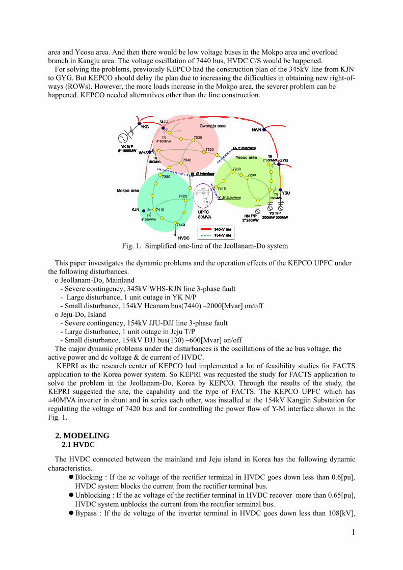
1. INTRODUCTION The Fig. 1 shows the local simplified power system of Jeollanam-Do in Korea. Jeollanam-Do is
divided into three sub-areas include Gwangju, Mokpo and Yeosu area. In the Gwangju area, Gwangju city is the large load and the six Youngkwang nuclear plants generate about 6000MW. In Yeosu area, Honam thermal plant and Yeosu thermal plant generate totally about 1000MW and Yeocheon industry area is major load, other areas are rural loads. In Mokpo area, most of all load is small city or rural, and specially 7440 bus(Haenam converter Station of HVDC) operates to supply the electric power(about 40% of the total load in Jeju island) toward the Jeju island through the DC cable under the sea.
If the 345kV line from GJU to WHS or from WHS to KJN could be opened, Mokpo area would be far from power source and would be supplied the power through the only 154kV line in the Kangju
area and Yeosu area. And then there would be low voltage buses in the Mokpo area and overload branch in Kangju area. The voltage oscillation of 7440 bus, HVDC C/S would be happened.
For solving the problems, previously KEPCO had the construction plan of the 345kV line from KJN to GYG. But KEPCO should delay the plan due to increasing the difficulties in obtaining new right-of-ways (ROWs). However, the more loads increase in the Mokpo area, the severer problem can be happened. KEPCO needed alternatives other than the line construction.
HVDC
UPFC80MVA
YK N/ P6*1000MW
GwangjuGwangju areaarea
YeosuYeosu areaarea
MokpoMokpo areaarea
HN T/ P2*280MW
YS T/ P200MW 300MW
YKGGJU
WHS
KJN
GYG
NWN
YSU7420
7415
7410
7380
TR3*500MVA
TR4*500MVA
TR500MVA
TR2*500MVA
TR500MVA
7440
G- Y Interface
Y- M Interface
M- G Interface
7530
7540
7520
79307280
345kV line154kV line
HVDC
UPFC80MVA
YK N/ P6*1000MW
GwangjuGwangju areaarea
YeosuYeosu areaarea
MokpoMokpo areaarea
HN T/ P2*280MW
YS T/ P200MW 300MW
YKGGJU
WHS
KJN
GYG
NWN
YSU7420
7415
7410
7380
TR3*500MVA
TR4*500MVA
TR500MVA
TR2*500MVA
TR500MVA
7440
G- Y Interface
Y- M Interface
M- G Interface
7530
7540
7520
79307280
HVDC
UPFC80MVA
YK N/ P6*1000MW
GwangjuGwangju areaarea
YeosuYeosu areaarea
MokpoMokpo areaarea
HN T/ P2*280MW
YS T/ P200MW 300MW
YKGGJU
WHS
KJN
GYG
NWN
YSU7420
7415
7410
7380
TR3*500MVA
TR4*500MVA
TR500MVA
TR2*500MVA
TR500MVA
7440
G- Y Interface
Y- M Interface
M- G Interface
7530
7540
7520
79307280
345kV line154kV line345kV line154kV line345kV line154kV line
Fig. 1. Simplified one-line of the Jeollanam-Do system This paper investigates the dynamic problems and the operation effects of the KEPCO UPFC under
the following disturbances. o Jeollanam-Do, Mainland - Severe contingency, 345kV WHS-KJN line 3-phase fault - Large disturbance, 1 unit outage in YK N/P - Small disturbance, 154kV Heanam bus(7440) –2000[Mvar] on/off o Jeju-Do, Island - Severe contingency, 154kV JJU-DJJ line 3-phase fault - Large disturbance, 1 unit outage in Jeju T/P - Small disturbance, 154kV DJJ bus(130) –600[Mvar] on/off The major dynamic problems under the disturbances is the oscillations of the ac bus voltage, the
active power and dc voltage & dc current of HVDC. KEPRI as the research center of KEPCO had implemented a lot of feasibility studies for FACTS
application to the Korea power system. So KEPRI was requested the study for FACTS application to solve the problem in the Jeollanam-Do, Korea by KEPCO. Through the results of the study, the KEPRI suggested the site, the capability and the type of FACTS. The KEPCO UPFC which has ±40MVA inverter in shunt and in series each other, was installed at the 154kV Kangjin Substation for regulating the voltage of 7420 bus and for controlling the power flow of Y-M interface shown in the Fig. 1.
2. MODELING
2.1 HVDC
The HVDC connected between the mainland and Jeju island in Korea has the following dynamic characteristics.
Blocking : If the ac voltage of the rectifier terminal in HVDC goes down less than 0.6[pu], HVDC system blocks the current from the rectifier terminal bus. Unblocking : If the ac voltage of the rectifier terminal in HVDC recover more than 0.65[pu], HVDC system unblocks the current from the rectifier terminal bus. Bypass : If the dc voltage of the inverter terminal in HVDC goes down less than 108[kV],
1

HVDC system bypasses the current from the inverter terminal bus. Unbypass : If the ac voltage of the inverter terminal in HVDC recovers more than 0.65[pu], HVDC system unbypass the current from the inverter terminal bus. Recovering Ramp : The recovering ramp of the dc voltage & the dc current in HVDC rectifier has the rate 0.2[pu/sec]. The ramp in inverter has the same rate. HVDC has the modulation control to maintain the frequency in Jeju island.
The CDC4 and SQBAUX in PSS/E models of PTI are used to represent the general dynamic
characteristics and the modulation control of HVDC in Korea.
Fig. 2. Block Diagram of CDC4 Fig. 3. Block Diagram of SQBAUX
2.2 UPFC
The dynamic response of the UPFC to a disturbance is very fast. Due to this fact no integrator is needed to model the UPFC and an algebraic model is sufficient for dynamics studies. An algebraic model in the PSS/E is a model that is called through CONET subroutine and contains no STATE. PQ control and Voltage insertion for series element are the two modes of operation that are implemented in this dynamics model.
A theoretical model for the UPFC consists of two voltage sources, one in series, corresponding to the series inverter and one in shunt corresponding to the shunt inverter, as shown in Fig.4. The two voltage sources are coupled by the real power flow Pdc which is drawn from the power system by the shunt inverter and injected into the power system by the series inverter. XP is the leakage reactance of shunt transformer.
PRL
Q
XL
BUS IBUS KBUS JBYPASS
+ Vs -
Xp
Pdc+
Vp-
Fig. 4. UPFC Dynamic Model
3. OPERATION EFFECTS OF UPFC The interactions between HVDC and UPFC in Jeollanam-Do are investigated using the PSS/E
models. The dynamic problems under the disturbances are investigated also. The following disturbances are simulated for investigation of the dynamic problems.
3.1 Jeollanam-Do, mainland system Three type disturbances are simulated in the local system of the Jeollanam-Do in which the UPFC
and HVDC was installed. The first type is the 3-phase fault of 345kV non-looped line. The second one
2

is the #3 unit outage of YK Nuclear Plant. Third one is the –2000[Mvar] reactor on/off instead of the various disturbances like the line-ground fault. The operation effects of UPFC with respect to the dynamic problems at the disturbances are analyzed. If the dynamic problems are transferred into Jeju island through the HVDC, the UPFC effects relating to the dynamics of HVDC are analyzed also.
Table 1. Contingency Cases Disturbance Type Main Land Island Severe Line Fault 345kV Line Fault 154kV Line Fault Large Disturbance 1000MVA Unit Off 70MVA Unit Off Small Disturbance -2000 MVar On/Off -600 MVar On/Off
3.1.1 Severe Line Fault This is the severe contingency since it makes the long electric distance from voltage source in
Kwangju area to load in Mokpo area. This results in significant weakening of the transmission line crossing the M-G interface.
Fig. 5 shows the voltage dynamics at the ac terminal bus of HVDC(7440) & UPFC(7420) with/without UPFC. The almost AC buses in Mokpo area have the voltage oscillations without UPFC operation, but the oscillations are mostly eliminated by UPFC operation. This Fig. 6 particularly shows the damping effect of the oscillations at the terminal buses of HVDC & UPFC during UPFC operation.
When the fault happens at 1.0[sec], HVDC acts the blocking of the rectifier since the terminal bus has the low voltage less than 0.6[pu], blocking reference voltage. The terminal bus of HVDC reaches the unblocking voltage 0.65[pu] at 5.1[sec], after the fault is cleared at 1.1[sec]. But the rectifier DC voltage of HVDC has the oscillation under the influence of the ac terminal bus of rectifier. Fig. 6 shows the dynamic relationship between AC and DC voltage of HVDC rectifier.
Fig. 5. Effects of Voltage Control at the Severe Fig. 6. DC Voltage Characteristics of HVDC
Line Fault in Mainland bus at Severe Line Fault in Mainland Fig. 7 shows the damping effects of the dc voltage oscillations at the rectifier of HVDC after the
during the UPFC operation. Fig. 8 shows the active power dynamics flows into the HVDC at the 345kV line 3-phase fault. UPFC is operated for maintaining the desired P and Q of the line, but UPFC doesn’t have the damping effect of the oscillation since post contingency. The reason of not damping the power oscillation near HVDC in Mokpo area is that the recovering action of HVDC after the blocking of the rectifier is more dominant than the constant power flow control action of UPFC. Another reason of not damping the power oscillation crossing M-Y interface is that the capability of UPFC is too small to handle the oscillation which happens in the whole Korea system.
3.1.2 Large Disturbance The large disturbance, #3 unit outage makes the large impact in YK nuclear plant complex. This
results in significant dynamic problems like sustained oscillations in the whole Kepco system including Mokpo area.
3

Fig. 7. Effects of DC Voltage Control of HVDC Fig. 8. Effects of Power Flow Control at Severe
bus at Severe Line Fault in Mainland Line Fault in Mainland
Fig. 9. Effects of Voltage Control at the Large Fig. 10. DC Voltage Characteristics of HVDC
Disturbance in Mainland bus at Large Disturbance in Mainland
Fig. 11. Effects of Power Flow Control at Large Fig. 12. Effects of DC Power Flow Control of
Disturbance in Mainland HVDC at Large Disturbance in Mainland Fig. 9 shows that the oscillations at the AC terminal buses of HVDC(7440) and UPFC(7420) is
dramatically damped by UPFC operation. Fig. 10 shows the damping effects of the DC voltage oscillation in HVDC during UPFC operation.
4

Fig. 11 shows that UPFC is controlling the constant power flow of the line at the large disturbance. Fig. 12 shows that the power that flows into the AC terminal bus of HVDC is oscillating owing to the large disturbance. The power oscillation is damped by UPFC operation as shown in the same figure.
Fig. 13 shows that the DC current and the firing angel of the HVDC is oscillating under the influence of the large disturbance. The oscillations in the HVDC are eliminated since the power oscillation which flow toward HVDC is damped by UPFC’s constant PQ control.
Fig. 13. Effects of DC Current Control of HVDC Fig. 14. Effects of Power Flow Control of
at Large Disturbance in Mainland Island at Large Disturbance in Mainland The active power dynamic problems happen in Jeju island because HVDC which connected with the
mainland makes the active power oscillation. Fig. 14 shows that the power oscillation between HVDC and Jeju island. And the oscillation is damped by the effect of UPFC operation.
Fig. 15 shows the electric power oscillation of the generators in Jeju Island. And the oscillation is damped by the effect of UPFC operation.
Fig. 15. Power Oscillation Damping of Island Fig. 16. Effects of Voltage Control at the Small
Plant at Large Disturbance in Mainland Disturbance in Mainland 3.1.3 Small Disturbance For the small disturbance, -2000[Mvar] reactor is connected instantly to 154kV bus nearby the
rectifier ac bus of HVDC. This results the small oscillation of the voltage and power only in Mokpo area. Fig. 16 shows that the oscillations at the AC terminal buses of HVDC(7440) and UPFC(7420) is well damped by UPFC operation. The voltage oscillation of the terminal ac bus influences the dc voltage of HVDC as shown in Fig. 16.
Fig. 17 shows that the small oscillation happens at the power flow toward HVDC. The oscillation is damped by UPFC operation, but the oscillation doesn’t influence the dynamic actions of HVDC like Fig. 18.
5
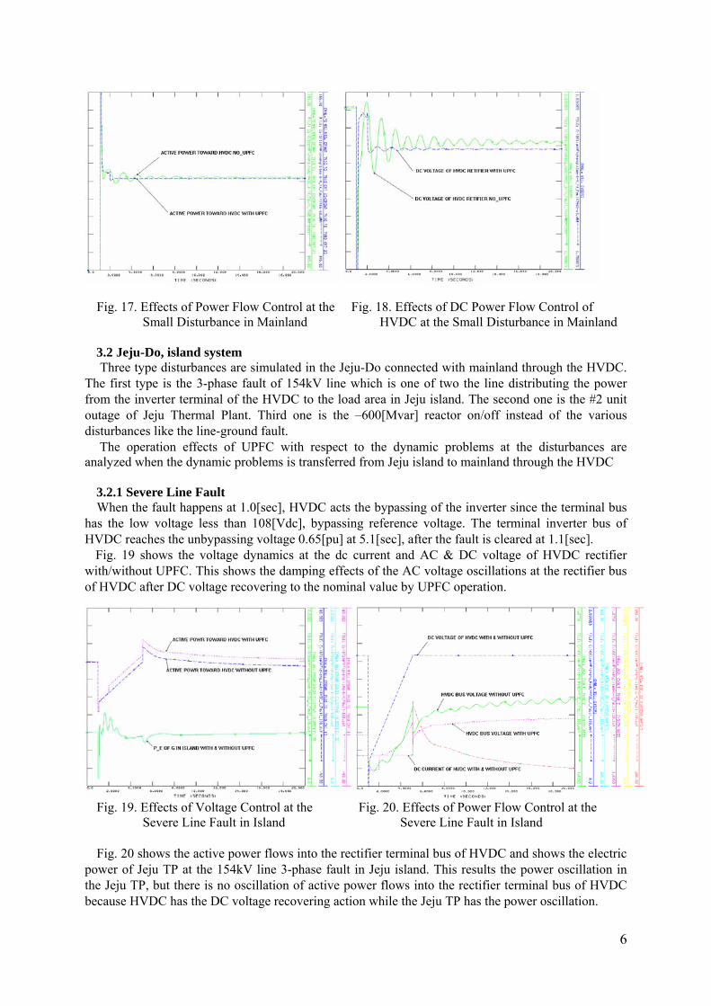
Fig. 17. Effects of Power Flow Control at the Fig. 18. Effects of DC Power Flow Control of
and
.2 Jeju-Do, island system imulated in the Jeju-Do connected with mainland through the HVDC.
T
th respect to the dynamic problems at the disturbances are an
.2.1 Severe Line Fault 1.0[sec], HVDC acts the bypassing of the inverter since the terminal bus
ha
ifier w
ig. 20 shows the active power flows into the rectifier terminal bus of HVDC and shows the electric
po
Small Disturbance in Mainland HVDC at the Small Disturbance in Mainl
3 Three type disturbances are s
he first type is the 3-phase fault of 154kV line which is one of two the line distributing the power from the inverter terminal of the HVDC to the load area in Jeju island. The second one is the #2 unit outage of Jeju Thermal Plant. Third one is the –600[Mvar] reactor on/off instead of the various disturbances like the line-ground fault.
The operation effects of UPFC wialyzed when the dynamic problems is transferred from Jeju island to mainland through the HVDC 3When the fault happens ats the low voltage less than 108[Vdc], bypassing reference voltage. The terminal inverter bus of
HVDC reaches the unbypassing voltage 0.65[pu] at 5.1[sec], after the fault is cleared at 1.1[sec]. Fig. 19 shows the voltage dynamics at the dc current and AC & DC voltage of HVDC rectith/without UPFC. This shows the damping effects of the AC voltage oscillations at the rectifier bus
of HVDC after DC voltage recovering to the nominal value by UPFC operation.
Fig. 19. Effects of Voltage Control at the Fig. 20. Effects of Power Flow Control at the Severe Line Fault in Island Severe Line Fault in Island
Fwer of Jeju TP at the 154kV line 3-phase fault in Jeju island. This results the power oscillation in
the Jeju TP, but there is no oscillation of active power flows into the rectifier terminal bus of HVDC because HVDC has the DC voltage recovering action while the Jeju TP has the power oscillation.
6

3.2.2 Large Disturbance Fig. 21 shows that the voltage at the AC terminal bus of HVDC(7440) and the power flow into the
re
. Effects of Voltage & Power Control
.2.3 Small Disturbance
at the AC terminal bus of HVDC(7440) and the power flow into the re
. CONTROL STRATEGY
reactive power injection can be used to control bus voltage. The voltage co
Table 2. Effects of Dynamic Voltage Control by UPFC Operation
ctifier bus of HVDC. HVDC increase the power gently since HVDC has the modulation controller, SQBAUX model which responses slowly. So there is no dynamic oscillation.
Fig. 21. Effects of Voltage & Power Flow Control Fig. 22
at the Large Disturbance in Island at the Small Disturbance in Island
3Fig. 22 shows the voltagectifier bus of HVDC. The voltage at terminal bus is oscillating slightly because of the low voltage
during the disturbance. But the oscillation is damped by UPFC operation. The oscillation of power flow doesn’t happen in Jeollanam-Do.
4
4.1 Voltage Control
It is well known that shuntmpensation by 80MVA KEPCO UPFC influences the voltage dynamics nearby UPFC in Jeollanam-
Do system of KOREA. The results of the dynamic simulations to investigate the operation effects of UPFC to damp out the voltage oscillation that happens at the various disturbances are shown in table 2.
Effects of UPFC operation Os
Voltage dynamicscillation Damping
Types of Disturbance Main nd Main and HVDC Isla HVDC Isl345kV Line Fault Ο X X Ο - -
1000MVA Unit Off Ο Ο Ο Ο Ο Ο
Mai
n
-2000MVar On/Off Ο X X Ο - - 154kV Line Fault Ο Ο Ο Ο Ο Ο 70MVA Unit Off X X Ο - - Ο
Isla
nd
-600 MVar On/Off X X Ο - - Ο .2 Power Flow Control
er flow in the line can be controlled independently using the series in
the V control mode which maintains the constant series injected voltage desired by operator. The V
4
The real and reactive powjected voltage. The series part of KEPCO UPFC has the two control modes. The one is the PQ
control mode that maintains the constant active and reactive power desired by operator. The other is
7

control mode is usually used, when the operator want the maximum series compensation of UPFC. The series compensation by 80MVA KEPCO UPFC influences the power flow dynamics nearby
KEPCO UPFC. The UPFC can damp out the power flow oscillation except the severe contingency, 345kV line fault in mainland as shown in table. It’d better change the control mode from PQ control mode to V control mode for the maximum series compensation, when the severe contingency happens.
Table 3. Effects of Dynamic Power flow Control by UPFC Operation Effects of UPFC operation Power dynamics
Oscillation Damping Types of Main H sland Disturbance VDC Island Main HVDC I
345kV Line Fault Ο X X X - - 1000MVA Unit Off Ο Ο Ο Ο Ο Ο
Mai
n
-2000MVar On/Off Ο X X Ο - - 154kV Line Fault X X Ο - - - 70MVA Unit Off X X Ο - - -
Isla
nd
-600 MVar On/Off X X Ο - - - Fig. 23 show si es ratio xam CO UPFC. UPFC is
operated on the PQ control mode until 1[sec] as the steady state. After the system has the large di
s the mulated results of the seri ope n e ple of KEP
sturbance, YK NP 1 unit outage happens at 1[sec], the dynamics of UPFC is simulated until 10[sec]. Finally the dynamics of UPFC is simulated until 20[sec] after the severe 345kV line fault happens at 10[sec] during 0.1[sec] and then fault clear at 10.1[sec].
Fig. 23. Dynamic Characteristics of UPFC though the changes of the operation mode
BIBLIO
nd Byung-Hoon Chang, " Development of FACTS Operation Technology (Phase 1 : Decision of a Type and a Spec. Draft for the Installation of a Pilot Plant)”. (KEPRI
[2] tem Engineering Symposium, KIEE, May, 1998).
[4] ansactions on
ress, 2000). [6] Jin-Boo, Choo, et al, “Development of FACTS Operation Technology(Phase 1 :
Decision of a Type and a Spec. Draft for the Installation of a Pilot Plant)”. (KEPRI Technical Report, April, 1999)
GRAPHY [1] Jin-Boo Choo a
Technical Report, April, 1999). In-Sup, Kim, “long-term Forecast of KEPCO System Planning and Operation, in Korea”. (Proceedings of 1998 Power Sys
[3] High Voltage Direct Current Handbook. (EPRI TR-104166S, 1994). Schauder, C., et al, “AEP Unified Power Flow Controller Performance”. (IEEE TrPower Delivery, March, 1999).
[5] Gyugyi, L., Hingorani, N. “Understanding FACTS : Concepts and Technology of Flexible AC Transmission Systems”. (IEEE p
8

9


