Embed Size (px)
Citation preview
B4 – 1 Amendment 2, TNA 134:1997
4 General message format and information elements coding
The figures and text in this clause describe message contents. Within each octet, the bit designated “bi t1” is transmitted
first, followed by bits 2, 3, 4, etc. Similarly, the octet shown at the top of each figure is sent first.
4.1 Overview
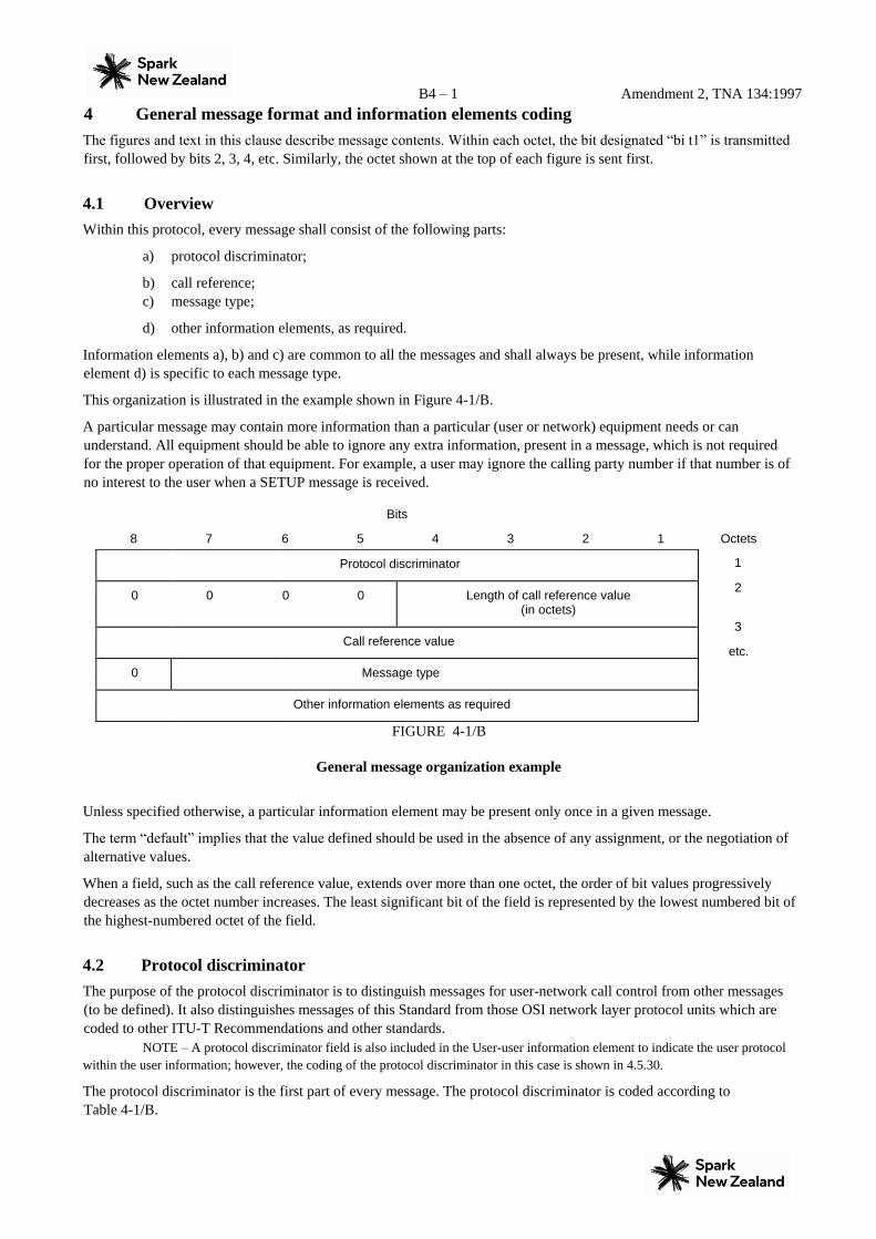
Within this protocol, every message shall consist of the following parts:
a) protocol discriminator;
b) call reference; c) message type;
d) other information elements, as required.
Information elements a), b) and c) are common to all the messages and shall always be present, while information
element d) is specific to each message type.
This organization is illustrated in the example shown in Figure 4-1/B.
A particular message may contain more information than a particular (user or network) equipment needs or can
understand. All equipment should be able to ignore any extra information, present in a message, which is not required
for the proper operation of that equipment. For example, a user may ignore the calling party number if that number is of
no interest to the user when a SETUP message is received.
Bits
8 7 6 5 4 3 2 1 Octets
1
2
3
etc.
FIGURE 4-1/B
General message organization example
Unless specified otherwise, a particular information element may be present only once in a given message.
The term “default” implies that the value defined should be used in the absence of any assignment, or the negotiation of
alternative values.
When a field, such as the call reference value, extends over more than one octet, the order of bit values progressively
decreases as the octet number increases. The least significant bit of the field is represented by the lowest numbered bit of
the highest-numbered octet of the field.
4.2 Protocol discriminator
The purpose of the protocol discriminator is to distinguish messages for user-network call control from other messages
(to be defined). It also distinguishes messages of this Standard from those OSI network layer protocol units which are
coded to other ITU-T Recommendations and other standards. NOTE – A protocol discriminator field is also included in the User-user information element to indicate the user protocol
within the user information; however, the coding of the protocol discriminator in this case is shown in 4.5.30.
The protocol discriminator is the first part of every message. The protocol discriminator is coded according to
Table 4-1/B.
Protocol discriminator
0 0 0 0 Length of call reference value (in octets)
Call reference value
0 Message type
Other information elements as required

B4 – 2 Amendment 2, TNA 134:1997
Bits
8 7 6 5 4 3 2 1 Octet
1
FIGURE 4-2/B
Protocol discriminator
TABLE 4-1/B
Protocol discriminator
8 7 6 5 4 3 2 1
0 0 0 0 0 0 0 0 through Assigned in subclause 4.5.30; not available for use in the message protocol
discriminator 0 0 0 0 0 1 1 1
0 0 0 0 1 0 0 0 ITU-T Recommendation Q.931/I.451 user-network call control messages
0 0 0 1 0 0 0 0 through Reserved for other network layer or layer 3 protocols, including Recommendation X.25 [5]
(Note)
0 0 1 1 1 1 1 1
0 1 0 0 0 0 0 0 through National use. Not used by
Telecom.
0 1 0 0 1 1 1 1
0 1 0 1 0 0 0 0 through Reserved for other network layer or layer 3 protocols, including Recommendation X.25
(Note)
1 1 1 1 1 1 1 0 All other values are reserved.
NOTE – These values are reserved to discriminate these protocol discriminators from the first octet of a Recommendation X.25
packet including general format identifier.
4.3 Call reference
The purpose of the call reference is to identify the call or facility registration/cancellation request at the local user-
network interface to which the particular message applies. The call reference does not have end-to-end significance
across ISDNs.
The call reference is the second part of every message. The call reference is coded as shown in Figure 4-3/B. The length
of the call reference value is indicated in octet 1, bits 1-4. The default maximum length of the call reference information
element is three octets long. The actions taken by the receiver are based on the numerical value of the call reference and
are independent of the length of the call reference information element.
At a minimum, all networks and users must be able to support a call reference value of one octet for a basic use-rnetwork
interface, and a call reference value of two octets for a primary rate interface. These lengths are supported by Telecom.
On a primary rate interface the network will accept a call reference value of one or two octets and will always send a call
reference value of two octets length.
Q.931/I.451 user-network call control messages
0 0 0 0 1 0
Protocol discriminator
0 0
B4 – 3 Amendment 2, TNA 134:1997
As a network option for a primary rate interface, the call reference value may be one octet also. In this case, a call
reference value up to 127 may be sent in one or two octets.
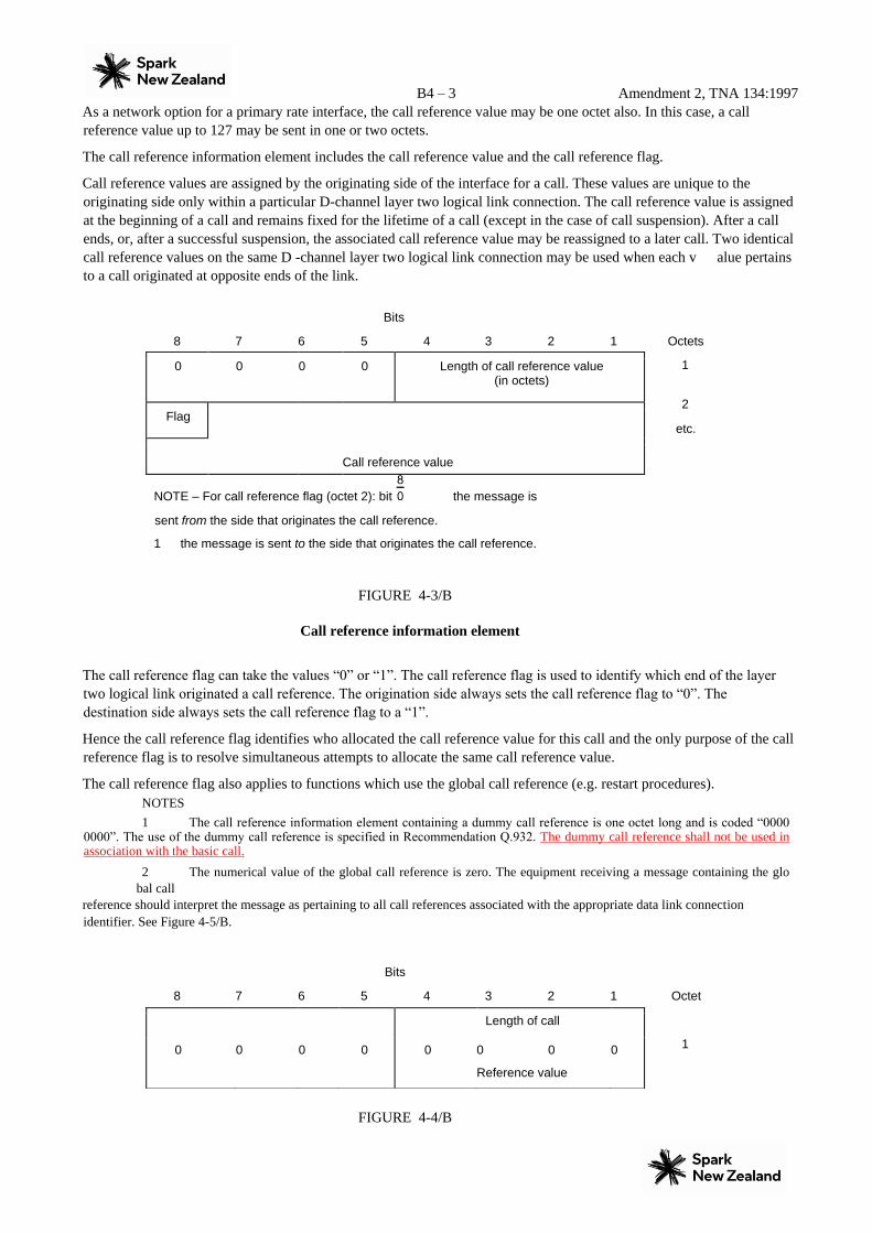
The call reference information element includes the call reference value and the call reference flag.
Call reference values are assigned by the originating side of the interface for a call. These values are unique to the
originating side only within a particular D-channel layer two logical link connection. The call reference value is assigned
at the beginning of a call and remains fixed for the lifetime of a call (except in the case of call suspension). After a call
ends, or, after a successful suspension, the associated call reference value may be reassigned to a later call. Two identical
call reference values on the same D -channel layer two logical link connection may be used when each v alue pertains
to a call originated at opposite ends of the link.
Bits
8 7 6 5 4 3 2 1 Octets
1
2
etc.
NOTE – For call reference flag (octet 2): bit the message is
sent from the side that originates the call reference.
1 the message is sent to the side that originates the call reference.
FIGURE 4-3/B
Call reference information element
The call reference flag can take the values “0” or “1”. The call reference flag is used to identify which end of the layer
two logical link originated a call reference. The origination side always sets the call reference flag to “0”. The
destination side always sets the call reference flag to a “1”.
Hence the call reference flag identifies who allocated the call reference value for this call and the only purpose of the call
reference flag is to resolve simultaneous attempts to allocate the same call reference value.
The call reference flag also applies to functions which use the global call reference (e.g. restart procedures). NOTES 1 The call reference information element containing a dummy call reference is one octet long and is coded “0000
0000”. The use of the dummy call reference is specified in Recommendation Q.932. The dummy call reference shall not be used in association with the basic call.
2 The numerical value of the global call reference is zero. The equipment receiving a message containing the glo
bal call reference should interpret the message as pertaining to all call references associated with the appropriate data link connection
identifier. See Figure 4-5/B.
Bits
8 7 6 5 4 3 2 1 Octet
1
FIGURE 4-4/B
0 0 0 0 Length of call reference value (in octets)
Flag
Call reference value
Length of call
0 0 0 0 0 0 0
Reference value
0

B4 – 4 Amendment 2, TNA 134:1997
Dummy call reference Bits
8 7 6 5 4 3 2 1 Octets
1
2
a) One octet call
reference value
Bits
8 7 6 5 4 3 2 1 Octets
1
2
3
b) Two octet call
reference value
FIGURE 4-5/B
Examples of the encoding for global call reference
4.4 Message type
The purpose of the message type is to identify the function of the message being sent.
The message type is the third part of every message. The message type is coded as shown in Figure 4-6/B and Table 4-
2/B.
Bit 8 is reserved for possible future use as an extension bit.
Bits
8 7 6 5 4 3 2 1 Octet
1
FIGURE 4-6/B
Message type TABLE
4-2/B
Length of call
0 0 0 0 0 0 0
Reference value
1
0/1 0 0 0 0 0 0 0
Flag Call reference value
Length of call
0 0 0 0 0 0 1
Reference value
0
0/1 0 0 0 0 0 0 0
Flag
0 0
Call reference value
0 0 0 0 0
0
0 Message type

B4 – 5 Amendment 2, TNA 134:1997
Message types
Bits
8 7 6 5 4 3 2 1
0 0 0 0 0 0 0 0 Escape to nationally specific message type (Note) 0 0 0 - - - - - Call
establishment message:
0 0 0 0 1 – ALERTING
0 0 0 1 0 – CALL PROCEEDING
0 0 1 1 1 – CONNECT
0 1 1 1 1 – CONNECT KNOWLEDGE
0 0 0 1 1 – PROGRESS
0 0 1 0 1 – SETUP
0 1 1 0 1 – SETUP ACKNOWLEDGE
0 0 1 - - - - - Call information phase message:
0 0 1 1 0 – RESUME
0 1 1 1 0 – RESUME ACKNOWLEDGE
0 0 0 1 0 – RESUME REJECT
0 0 1 0 1 – SUSPEND
0 1 1 0 1 – SUSPEND ACKNOWLEDGE
0 0 0 0 1 – SUSPEND REJECT 0 0 0 0 0 –
USER INFORMATION
0 1 0 - - - - - Call clearing messages:
0 0 1 0 1 – DISCONNECT
0 1 1 0 1 – RELEASE
1 1 0 1 0 – RELEASE COMPLETE
0 0 1 1 0 – RESTART
0 1 1 1 0 – RESTART ACKNOWLEDGE 0 1 1 - - - - -
Miscellaneous messages:
0 0 0 0 0 – SEGMENT
1 1 0 0 1 – CONGESTION CONTROL
1 1 0 1 1 – INFORMATION
0 1 1 1 0 – NOTIFY
1 1 1 0 1 – STATUS
1 0 1 0 1 – STATUS ENQUIRY
NOTE – When used, the message type is defined in the following octet(s), according to the
national specification.
4.5 Other information elements
4.5.1 Coding rules
The coding of other information elements follows the coding rules described below. These rules are formulated to allow
each equipment which processes a message to find information elements important to it, and yet remain ignorant of
information elements not important to that equipment.
Two categories of information elements are defined:
a) single octet information elements (see diagrams a) and b) of Figure 4-7/B);
b) variable length information elements (see diagram c) of Figure 4-7/B).

B4 – 6 Amendment 2, TNA 134:1997
Bits
8 7 6 5 4 3 2 1 Octet
1
Octet
1
b) Single octet
information element format (type 2)
Bits
8 7 6 5 4 3 2 1 Octet
1
2
3 etc.
c) Variable length
information element format
FIGURE 4-7/B
Formats of information elements For the information elements listed below, the coding of the information element identifier bits is summarized in
Table 4-3/B.
TABLE 4-3/B
Information element identifier coding
Bits
8 7 6 5
1 : : :
4 3 2 1
- - - - Single octet information elements:
Reference
(subclause)
Maximum length
(octets) (Note 1)
0 0 0 - - - - Reserved
0 0 1 - - - - Shift (Note 2) 4.5.3/4.5.4 11
0 1 0 0 0 0 0 More data 4.5.20 11
0 1 0 0 0 0 1 Sending complete 4.5.27 11
0 1 1 - - - - Congestion level 4.5.14 11
1 0 1 - - - - Repeat indicator 4.5.24 11
1 Information element identifier
Contents of information element
a) Single octet information element format (type 1)
Bits
8 7 6 5 4 3 2 1
1 Information element identifier
0 Information element identifier
Length of contents of information element (octets)
Contents of information element

B4 – 7 Amendment 2, TNA 134:1997
0 : : : : : : : Variable length information element:
0 0 0 0 0 0 0 Segmented message 4.5.26 14
0 0 0 0 1 0 0 Bearer capability (Note 2) 4.5.5 12
0 0 0 1 0 0 0 Cause (Note 2) 4.5.12 32
0 0 1 0 0 0 0 Call identity 4.5.6 10
0 0 1 0 1 0 0 Call state 4.5.7 13
0 0 1 1 0 0 0 Channel identification (Note 2) 4.5.13 (Note 4)
0 0 1 1 1 1 0 Progress indicator (Note 2) 4.5.23 14
0 1 0 0 0 0 0 Network-specific facilities (Note 2) 4.5.21 (Note 4)
0 1 0 0 1 1 1 Notification indicator 4.5.22 13
0 1 0 1 0 0 0 Display 4.5.16 34/82
0 1 0 1 0 0 1 Date/time 4.5.15 18
0 1 0 1 1 0 0 Keypad facility 4.5.18 34
0 1 1 0 0 1 0 Information request 4.7.4 3
0 1 1 0 1 0 0 Signal (Note 2) 4.5.28 13
0 1 1 1 0 0 0 Feature activation 4.7.3 4
1 0 0 0 0 0 0 Information rate 4.6.3 16
1 0 0 0 0 1 0 End-to-end transit delay 4.6.2 11
1 0 0 0 0 1 1 Transit delay selection and indication 4.6.9 15
1 0 0 0 1 0 0 Packet layer binary parameters 4.6.4 13
1 0 0 0 1 0 1 Packet layer window size 4.6.5 14
1 0 0 0 1 1 0 Packet size 4.6.6 14
1 0 0 0 1 1 1 Closed user group 4.6.1 17
1 0 0 1 0 1 0 Reverse charge indication 4.6.8 13
1 0 0 1 1 0 0 Connected number 4.7.1 21
1 0 0 1 1 0 1 Connected subaddress 4.7.2 23
1 1 0 1 1 0 0 Calling party number 4.5.10 21
1 1 0 1 1 0 1 Calling party subaddress 4.5.11 23 TABLE 4-3/B (concl.)
Information element identifier coding
1 1 1 0 0 0 0 Called party number 4.5.8 27
1 1 1 0 0 0 1 Called party subaddress 4.5.9 23
1 1 1 0 1 0 0 Redirecting number 4.6.7 4.7.5 (Note 4) 29
1 1 1 1 0 0 0 Transit network selection (Note 2) 4.5.29 16
1 1 1 1 0 0 1 Restart indicator 4.5.25 13
1 1 1 1 1 0 0 Low layer compatibility (Note 2) 4.5.19 18 16
1 1 1 1 1 0 1 High layer compatibility (Note 2) 4.5.17 15
1 1 1 1 1 1 0 User-user 4.5.30 35/131
1 1 1 1 1 1 1 Escape for extension (Note 3) All other values are reserved (Note 5)

B4 – 8 Amendment 2, TNA 134:1997
NOTES
1 The length limits described for the variable length information elements take into account only the present CCITT standardized coding values. Future enhancements and expansions to this Specification will not be restricted to these limits.
2 This information element may be repeated.
3 This escape mechanism is limited to codesets 4, 5, 6 and 7 (see 4.5.2). When the escape for extension is used, the
information element identifier is contained in octet-group 3 and the content of the information elemen t follows in the
subsequent octets as shown in Figure 4-8/B.
4 The maximum length is network dependent. The maximum length of the Channel identification information element is 3 octets for basic rate interfaces and 9 octets for primary rate interfaces.
5 The reserved values with bits 5-8 coded “0000” are for future information elements for which comprehension by the
receiver is required (see 5.8.7.1).
The descriptions of the information elements below are organized in alphabetical order. However, there is a particular
order of appearance for each information element in a message within each codeset (see 4.5.2). The code values of the
information element identifier for the variable length formats are assigned in ascending numerical order, according to the
actual order of appearance of each information element in a message. This allows the receiving equipment to detect the
presence or absence of a particular information element without scanning through an entire message.
Single octet information elements may appear at any point in the message. Two types of single octet information
elements have been defined. Type 1 elements provide the information element identification in bit positions 7, 6, 5. The
value “010” in these bit positions is reserved for Type 2 single octet elements.
Where the description of information elements in this Specification contains spare bits, these bits are indicated as being
set to “0”. In order to allow compatibility with future implementation, messages should not be rejected simply because a
spare bit is set to “1”.
The second octet of a variable length information element indicates the total length of the contents of that information
element regardless of the coding of the first octet (i.e. the length starting with octet 3). It is the binary coding of
the number of octets of the contents, with bit 1 as the least significant bit (2°).
An optional variable-length information element may be present, but empty. For example, a SETUP message may
contain a called party number information element, the content of which is of zero length. This should be interpreted by
the receiver as equivalent to that information element being absent. Similarly, an absent information element should be
interpreted by the receiver as equivalent to that information element being empty.
The following rules apply for the coding of variable length information elements (octets 3, etc.):
a) The first digit in the octet number identifies one octet or a group of octets.
b) Each octet group is a self contained entity. The internal structure of an octet group may be defined in
alternative ways.
c) An octet group is formed by using some extension mechanism. The preferred extension mechanism is to
extend an octet (N) through the next octet(s) (Na, Nb, etc.) by using bi t8 in each octet as an extension bit.
The bit value “0” indicates that the octet continues through the next octet. The bit value “1” indicates that
this octet is the last octet. If one octet (Nb) is present, also the preceding octets (N and Na) must be
present.
In the format descriptions appearing in 4.5.5 etc., bit 8 is marked “0/1 ext,” if another octet follows. Bit 8
is marked “1 ext,” if this is the last octet in the extension domain.
Additional octets may be defined later (“1 ext.” changed to “0/1 ext.”) and equipments shall be prepared to
receive such additional octets although the equipment need not be able to interpret or act upon the content
of these octets.
d) In addition to the extension mechanism defined above, an oct et (N) may be extended through the next
octet(s) (N1, N2 etc.) by indications in bits 7-1 (of octet N).
e) The mechanisms in c) and d) may be combined. Mechanism c) shall take priority in the ordering, such
that all octets Na, Nb, etc. shall occur before octets N1, N2, etc. This rule shall apply even where the
extension to octets N1, N2, etc. is indicated in one of octet Na, Nb, etc.

B4 – 9 Amendment 2, TNA 134:1997
f) Similar conventions apply even when mechanism d) is being repeated, i.e. octets N.1 shall occur before
octets N.1.1, N.1.2, etc.
g) Optional octets are marked with asterisks (*). NOTES
1 It is not possible to use mechanism c) repeatedly, i.e. it is not possible to construct an octet 4a as this would become octet 4b.
2 Protocol designers should exercise care in using multiple extension mechanisms to ensure that a unique
interpretation of the resultant coding is possible.
3 For a number of information elements there is a field that defines the coding standard. When the coding standard defines a national standard it is recommended that the national standard be structured similar to the information element defined in
this Specification.
Bits
8 7 6 5 4 3 2 1 Octets
1
2
3
4 etc.
FIGURE 4-8/B
Information element format using escape for extension
4.5.2 Extensions of codesets
There is a certain number of possible information element identifier values using the formatting rules described in 4.5.1;
128 from the variable length information element format and at least 8 from the single octet information element format.
One value in the single octet format is specified for shift operations described below. One other value in both the single
octet and variable format is reserved. This leaves at least 133 information element identifier values available for
assignment.
It is possible to expand this structure to eight codesets of at least 133 information element identifier values each. One
common value in the single octet format is employed in each codeset to facilitate shifting from one codeset to another.
The contents of this Shift information element identifies the codeset to be used for the next information element or
elements. The codeset in use at any given time is referred to as the “active codeset”. By convention, codeset 0 is the
initially active codeset.
Two codeset shifting procedures are supported: locking shift and non-locking shift.
Codeset 4 is reserved for use by ISO/IEC standards.
Codeset 5 is reserved for information elements reserved for national use. Not currently used by Telecom for public and
Centrex interfaces.
Codeset 6 is reserved for information elements specific to the local network (either public or private). Not currently used
by Telecom for public and Centrex interfaces.
Codeset 7 is reserved for user-specific information elements. Not used by Telecom.
The coding rules specified in 4.5.1 shall apply for information elements belonging to any active codeset.
0
Escape for extension
1 1 1 1 1 1 1
Length of information element contents
1 ext. Information element identifier
Contents of information element

B4 – 10 Amendment 2, TNA 134:1997
Transitions from one active codeset to another (i.e. by means of the locking shift procedure) may only be made to a
codeset with a higher numerical value than the codeset being left.
An information element belonging to codesets 4, 5, 6, or 7, may appear together with information elements belonging to
codeset 0 (being the active codeset) by using the non-locking shift procedure (see 4.5.4).
A user of network equipment shall have the capability to recognize a Shift information element and to determine the
length of the following information element, although the equipment need not be able to interpret and act upon the
content of the information element. This enables the equipment to determine the start of a subsequent information
element.
Codeset 7 information element shall be handled according to the procedures for unrecognized information elements (see
5.8.7.1) by the first exchange in the local network, unless allowed by a future service definition, bilateral agreement, or
provision is made to support this across the local network for a specific user.
Codeset 6 is reserved for information elements specific to the local network (either public or private). As such they do
not have significance across the boundaries between local networks, or across a national, or international boundary.
Therefore, codeset 6 information elements shall be handled according to the procedures for unrecognized information
elements (see 5.8.7.1) beyond local network boundary, unless allowed by bilateral agreement.
Codeset 5 is reserved for information elements reserved for national use. As such they do not have significance across an
international boundary. Therefore, codeset 5 information elements shall be handled according to the procedures for
unrecognized information elements (see 5.8.7.1) at the first exchange beyond the international boundary, unless there are
bilateral agreements to the contrary.
Codeset 4 is reserved for information elements specified in ISO/IEC standards.
4.5.3 Locking shift procedure
The locking shift procedure employs an information element to indicate the new active codeset. The specified codeset
remains active until another locking shift information element is encountered which specifies the use of another codeset.
For example, codeset 0 is active at the start of message content analysis. If a locking shift to codeset 5 is encountered,
the next information elements will be interpreted according to the information element identifiers assigned in codeset 5,
until another shift information element is encountered.
This procedure is used only to shift to a higher order codeset than the one being left.
The locking shift is valid only within that message which contains the locking Shift information element. At the start of
every message content analysis, the active codeset is codeset 0.
The locking Shift information element uses the single octet information element format and coding shown in Figure 4-
9/B and Table 4-4/B.
4.5.4 Non-locking shift procedure
The non-locking shift procedure provides a temporary shift to the specified lower or higher codeset. The non-locking
shift procedure uses a single octet information element to indicate the codeset to be used to interpret the next single
information element. After the interpretation of the next single information element, the active codeset is again used for
interpreting any following information elements. For example, codeset 0 is active at the beginning of message content
analysis. If a non-locking shift to codeset 6 is encountered, only the next information element is interpreted according to
the information element identifiers assigned in codeset 6. After this information element is interpreted, codeset 0 will
again be used to interpret the following information elements. A non-locking Shift information element indicating the
current codeset shall not be regarded as an error.
Bits
8 7 6 5 4 3 2 1 Octet
1
↑
Shift
1 0 0
identifier
1 0 New codeset identification

B4 – 11 Amendment 2, TNA 134:1997
“0” in this position
indicates locking shift
FIGURE 4-9/B
Locking Shift information element
TABLE 4-4/B
Locking Shift information element
Codeset identification (bits 3 to 1):
Bits
3 2 1
0 0 0 Not applicable
0 0 1 to
Reserved
0 1 1 1 0 0 Codeset 4: information elements for ISO/IEC use
1 0 1 Codeset 5: information elements for national use. Not currently used by Telecom .
1 1 0 Codeset 6: information elements specific to the local network (either public or private) Not currently used by Telecom.
1 1 1 Codeset 7: user-specific information elements Not used by Telecom. A locking Shift information element shall not follow directly on a non-locking Shift information element. If this
combination is received, it shall be interpreted as though a locking Shift information element only had been received.
The non-locking Shift information element uses the single octet information element format and coding shown in
Figure 4-10/B and Table 4-5/B.
Bits
8 7 6 5 4 3 2 1 Octet
1
↑
“1” in this position
indicates non-locking
shift
FIGURE 4-10/B
Non-locking Shift information element
Shift Temporary
1 0 0 1 1 codeset
identifier identification

B4 – 12 Amendment 2, TNA 134:1997
TABLE 4-5/B
Non-locking Shift information element
Codeset identification (bits 3 to 1):
Bits
3 2 1
0 0 0 Codeset 0 (initially active): Q.931 information elements
0 0 1 to
Reserved
0 1 1
1 0 0 Codeset 4: information elements for ISO/IEC use
1 0 1 Codeset 5: information elements for national use. Not currently used by Telecom.
1 1 0 Codeset 6: information elements specific to the local network (either public or private). Not currently used by Telecom.
1 1 1 Codeset 7: user-specific information elements. Not used by Telecom. 4.5.5 Bearer capability
The purpose of the Bearer capability information element is to indicate a requested Recommendation I.231 [6] bearer
service to be provided by the network. It contains only information which may be used by the network (see Annex I).
The use of the Bearer capability information element in relation to compatibility checking is described in Annex B.
The Bearer capability information element is coded as shown in Figure 4-11/B and Table 4-6/B.
No default bearer capability may be assumed by the absence of this information element.
The maximum length of this information element is 12 octets. NOTE – Future extensions to the codings of the Bearer capability information element should not be in conflict with the
initially defined coding of the Low layer compatibility information element. See 4.5.19. Bits
8 7 6 5 4 3 2 1 Octets

B4 – 13 Amendment 2, TNA 134:1997
1
2
3
4
4.1* (Note 1)
5*
5a* (Note 2)
5b* (Note 3)
5b* (Note 4)
5c* (Note 2)
5d* (Note 2)
6*
7*
Bearer capability
0 0 0 0 0 1 0
Information element identifier
0
Length of the bearer capability contents
1 ext. Coding standard Information transfer capability
1 ext. Transfer mode Information transfer rate
1 ext. Rate multiplier
0/1 ext. 0 1
Layer 1 ident. User information layer 1
protocol
0/1 ext. Synch./ asynch Negot. User rate
0/1 ext. Intermediate rate NIC on Tx NIC on Rx Flow control
on Tx Flow
control on Rx
0 Spare
0/1 ext. Hdr/ no Hdr Multi frame Mode LLI negot. Assignor/ee In-band neg. 0 Spare
0/1 ext. Number of stop bits Number of data bits Parity
1 ext. Duplex mode Modem type
1 ext. 1 0
Layer 2 ident. User information layer 2 protocol
1 ext. 1 1
Layer 3 ident. User information layer 3 protocol

B4 – 14 Amendment 2, TNA 134:1997
NOTES
1 This octet is required if octet 4 indicates multirate (64 kbit/s base rate). Otherwise, it shall not be present.
2 This octet may be present if octet 3 indicates unrestricted digital information and octet 5 indicates either of the
CCITT standardized rate adaptions V.110 and X.30 or V.120 [9]. It may also be present if octet 3 indicates 3.1
kHz audio and octet 5 indicates G.711.
3 This octet is significant only if octet 5 indicates CCITT standardized rate adaption (see Recommendation V.110
[7] and X.30 [8]
4 This octet is significant only if octet 5 indicates CCITT standardized rate adaption see Recommendation V.120
[9].
FIGURE 4-11/B
Bearer capability information element

B4 – 15 Amendment 2, TNA 134:1997
TABLE 4-6/B Bearer
capability information element
Coding standard (octet 3) Bits 7 6
0 0 CCITT standardized coding as described below 0 1 ISO/IEC standard (Note 1). Not used
by Telecom. 1 0 National standard (Note 1). Not used by Telecom.
1 1 Standard defined for the network (either public or private) present on the network side of the interface (Note 1). Not used by Telecom.
NOTE 1 – These other coding standards should be used only when the desired bearer capability cannot be represented with the CCITT-standardized coding.
Information transfer capability (octet 3) Bits 5 4 3 2 1
0 0 0 0 0 Speech. Only A-law encoded speech will be supported in New Zealand. A-law will be assumed if octet 5 is omitted.
0 1 0 0 0 Unrestricted digital information
0 1 0 0 1 Restricted digital information
1 0 0 0 0 3.1 kHz audio
1 0 0 0 1 Unrestricted digital information with tones/announcements (Note 2). This bearer capability is not currently supported by Telecom. Users can code the Bearer capability as 64 kbit/s unrestricted and code the Low layer compatibility as UDI-TA.
1 1 0 0 0 Video. This bearer capability is not currently supported by Telecom. Users can code the Bearer capability as 64 kbit/s unrestricted and code the Low layer compatibility as Video.
All other values are reserved. NOTE 2 – Unrestricted digital information with tones/announcements (UDI-TA) is the new information transfer attribute
value that had previously been named “7 kHz audio” in Recommendation Q.931 (1988). Transfer mode (octet 4)
Bits 7 6
0 0 Circuit mode
1 0 Packet mode All other values are reserved.
Information transfer rate (octets 4 , bits 5 to 1) Bits
5 4 3 2 1 Circuit mode Packet-mode
0 0 0 0 0 – This code shall be used for packet mode calls
1 0 0 0 0 64 kbit/s –
1 0 0 0 1 2 × 64 kbit/s – Not currently used by Telecom. 1 0 0 1 1 384 kbit/s –
Not currently used by Telecom. 1 0 1 0 1 1536 kbit/s – Not currently used by
Telecom.
1 0 1 1 1 1920 kbit/s – Not currently used by Telecom.
1 1 0 0 0 Multirate (64 kbit/s base rate) Not currently used by Telecom. All other values are reserved.
NOTE 1– When the information transfer rate 2 × 64 kbit/s is used, the coding of octets 3 and 4 refer to both 64 kbit/s
channels. NOTE 2 – Additional attributes are defined in Table 4-7/B.

B4 – 16 Amendment 2, TNA 134:1997
TABLE 4-6/B (cont.)
Bearer capability information element
Rate mutiplier (octet 4.1) NOTE 5 – Coded as a binary representation of the multiplier to the base rate. The multiplier can take any value from 2 up to the maximum number of B-channels available on the interface.
User information layer 1 protocol (octet 5)
Bits
5 4 3 2 1
0 0 0 0 1 CCITT standardized rate adaption V.110 and X.30. This implies the presence of octet 5a and optionally octets 5b, 5c and 5d as defined below.
0 0 0 1 0 Recommendation G.711 [10] µ-law. Not used by Telecom.
0 0 0 1 1 Recommendation G.711 A-law
0 0 1 0 0 Recommendation G.721 [11] 32 kbit/s ADPCM and Recommendation I.460. Not currently used by Telecom.
0 0 1 0 1 Recommendations H.221 and H.242. Not currently used by Telecom.
0 0 1 1 1 Non-CCITT standardized rate adaption. This implies the presence of octet 5a and, optionally, octets 5b, 5c
and 5d. The use of this code point indicates that the user rate spec ified in octet 5a is defined by the user. Additionally, octets 5b, 5c and 5d, if present, are defined consistent with the user specified rate adaption. Not used by Telecom.
0 1 0 0 0 CCITT standardized rate adaption V.120 [9]. This implies the presence of octets 5a and 5b as defined below, and optionally octets 5c and 5d. Not currently used by Telecom.
0 1 0 0 1 CCITT standardized rate adaption X.31 [14] HDLC flag stuffing. Not currently used by Telecom.
All other values are reserved.
NOTE – If the transfer mode is “circuit mode”, and if the information transfer capability is “unrestricted digital information”
or “restricted digital information”; and if the user information layer 1 protocol is to be identified only to the addressed entity octet
5 shall be omitted. If the transfer mode is packet mode, octet 5 may be omitted. Otherwise, octet 5 shall be present.
Synchronous/Asynchronous (octet 5a)
Bit
7
0 Synchronous data
1 Asynchronous data
NOTE 1 – Octets 5b – 5d may be omitted in the case of synchronous user rates.
Negotiation (octet 5a)
Bits 0 In-band negotiation not possible
1 In-band negotiation not possible
NOTE 2 – See Recommendations V.110 [7] and X.30 [8] or modem type recommendation
B4 – 17 Amendment 2, TNA 134:1997
TABLE 4-6/B (cont.)
Bearer capability information element
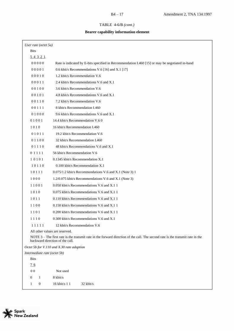
User rate (octet 5a)
Bits
5 4 3 2 1
0 0 0 0 0 Rate is indicated by E-bits specified in Recommendation I.460 [15] or may be negotiated in-band
0 0 0 0 1 0.6 kbit/s Recommendations V.6 [16] and X.1 [17]
0 0 0 1 0 1.2 kbit/s Recommendation V.6
0 0 0 1 1 2.4 kbit/s Recommendations V.6 and X.1
0 0 1 0 0 3.6 kbit/s Recommendation V.6
0 0 1 0 1 4.8 kbit/s Recommendations V.6 and X.1
0 0 1 1 0 7.2 kbit/s Recommendation V.6
0 0 1 1 1 8 kbit/s Recommendation I.460
0 1 0 0 0 9.6 kbit/s Recommendations V.6 and X.1
0 1 0 0 1 14.4 kbit/s Recommendation V.6 0
1 0 1 0 16 kbit/s Recommendation I.460
0 1 0 1 1 19.2 kbit/s Recommendation V.6
0 1 1 0 0 32 kbit/s Recommendation I.460
0 1 1 1 0 48 kbit/s Recommendations V.6 and X.1
0 1 1 1 1 56 kbit/s Recommendation V.6
1 0 1 0 1 0.1345 kbit/s Recommendation X.1
1 0 1 1 0 0.100 kbit/s Recommendation X.1
1 0 1 1 1 0.075/1.2 kbit/s Recommendations V.6 and X.1 (Note 3) 1
1 0 0 0 1.2/0.075 kbit/s Recommendations V.6 and X.1 (Note 3)
1 1 0 0 1 0.050 kbit/s Recommendations V.6 and X.1 1
1 0 1 0 0.075 kbit/s Recommendations V.6 and X.1 1
1 0 1 1 0.110 kbit/s Recommendations V.6 and X.1 1
1 1 0 0 0.150 kbit/s Recommendations V.6 and X.1 1
1 1 0 1 0.200 kbit/s Recommendations V.6 and X.1 1
1 1 1 0 0.300 kbit/s Recommendations V.6 and X.1
1 1 1 1 1 12 kbit/s Recommendation V.6
All other values are reserved.
NOTE 3 – The first rate is the transmit rate in the forward direction of the call. The second rate is the transmit rate in the backward direction of the call.
Octet 5b for V.110 and X.30 rate adaption
Intermediate rate (octet 5b)
Bits
7 6
0 0 Not used
0 1 8 kbit/s
1 0 16 kbit/s 1 1 32 kbit/s

B4 – 18 Amendment 2, TNA 134:1997
TABLE 4-6/B (cont.)
Bearer capability information element
Network independent clock (NIC) on transmission (Tx) (octet 5b) (Note 1)
Bit
5
0 Not required to send data with network independent clock
1 Required to send data with network independent clock
NOTE 1 – Refers to transmission in the forward direction of the call.
NOTE 2 – See Recommendations V.110 [7] and X.30.
Network independent clock (NIC) on reception (Rx) (octet 5b) (Note 3)
Bit
4
0 Cannot accept data with network independent clock (i.e. sender does not support this optional procedure)
1 Can accept data with network independent clock (i.e. sender does support this optional procedure) NOTE 3 – Refers
to transmission in the backward direction of the call.
NOTE 4 – See Recommendations V.110 [7] and X.30 [8].
Flow control on transmission (Tx) (octet 5b) (Note 5)
Bit
3
0 Not required to send data with flow control mechanism
1 Required to send data with flow control mechanism
NOTE 5 – Refers to transmission in the forward direction of the call.
NOTE 6 – See Recommendations V.110 and X.30.
Flow control on reception (Rx) (octet 5b) (Note 7)
Bit
2
0 Cannot accept data with flow control mechanism (i.e. sender does not support this optional procedure)
1 Can accept data with flow control mechanism (i.e. sender does support this optional procedure) NOTE 7 –
Refers to transmission in the backward direction of the call NOTE 8 – See Recommendations V.110 and X.30.
Octet 5b for V.120 [9] rate adaption
Rate adaption header/no header (octet 5b)
Bit
7
0 Rate adaption header not included
1 Rate adaption header included
Multiple frame establishment support in data link (octet 5b)
Bit
6
0 Multiple frame establishment not supported. Only UI frames allowed
1 Multiple frame establishment supported

B4 – 19 Amendment 2, TNA 134:1997
Bearer capability information element
TABLE 4-6/B
Mode of operation (octet 5b) Bit 5
0 Bit transparent mode of operation
1 Protocol sensitive mode of operation Logical link identifier negotiation (octet 5b)
Bit 4
0 Default, LLI = 256 only
1 Full protocol negotiation (Note) NOTE – A connection over which protocol negotiation will be executed is indicated in bit 2 of octet 5b.
Assignor/assignee (octet 5b) Bit 3
0 Message originator is “Default assignee”
1 Message originator is “Assignor only” In-band/out-band negotiation (octet 5b)
Bit 2
0 Negotiation is done with USER INFORMATION messages on a temporary signalling connection 1 Negotiation is
done in-band using logical link zero
Number of stop bits (octet 5c) Bits 7 6
0 0 Not used
0 1 1 bit
1 0 1.5 bits
1 1 2 bits Number of data bits excluding parity Bit if present (octet 5c)
Bits 5 4
0 0 Not used
0 1 5 bits
1 0 7 bits
1 1 8 bits Parity information (Octet 5c)
Bits 3 2 1
0 0 0 Odd
0 1 0 Even
0 1 1 None
1 0 0 Forced to 0
1 0 1 Forced to 1 All other values are reserved.
TABLE 4-6/B (concl.)

B4 – 20 Amendment 2, TNA 134:1997
Bearer capability information element
Mode duplex (octet 5d)
Bit
7
0 Half duplex
1 Full duplex
Modem type (octet 5d)
Bits
6 5 4 3 2 1
0 0 0 0 0 0 through national use
0 0 0 1 0 1
0 1 0 0 0 1 Recommendation V.21 [55] 0
1 0 0 1 0 Recommendation V.22 [56]
0 1 0 0 1 1 Recommendation V.22 bis [57]
0 1 0 1 0 0 Recommendation V.23 [58] 0
1 0 1 0 1 Recommendation V.26 [59]
0 1 0 1 1 0 Recommendation V.26 bis [60]
0 1 0 1 1 1 Recommendation V.26 ter [61]
0 1 1 0 0 0 RecommendationV.27 [62]
0 1 1 0 0 1 Recommendation V.27 bis [63]
0 1 1 0 1 0 Recommendation V.27 ter [64]
0 1 1 0 1 1 Recommendation V.29 [65] 0 1 1 1 0 1 Recommendation V.32 [66]
1 0 0 0 0 0 through national use
1 0 1 1 1 1
1 1 0 0 0 0 through user specified
1 1 1 1 1 1
All other values reserved.
User information layer 2 protocol (octet 6)
Bits
5 4 3 2 1
0 0 0 1 0 Recommendation Q.921/I.441 [3] 0 0
1 1 0 Recommendation X.25 [5], link layer
All other values are reserved.
NOTE 1 – If the transfer mode is “packet mode”, octet 6 shall be present. For other cases, if the user layer 2 protocol is to be
identified to the network, then octet 6 shall be present; otherwise octet 6 shall be omitted. User information layer 3 protocol (octet
7)
Bits
5 4 3 2 1
0 0 0 1 0 Recommendation Q.931/I.451 0 0 1 1
0 Recommendation X.25, packet layer
All other values are reserved.
NOTE 2 – If the user information layer 3 protocol is to be identified to the network, octet 7 shall be present; otherwise octet 7
shall be omitted.

B4 – 21 Amendment 2, TNA 134:1997
Bearer capability information element

B4 – 22 Amendment 2, TNA 134:1997
TABLE 4-7/B
Bearer capability attributes
BC Attributes Additional Attributes
Transfer mode
Information transfer
capability Structure Configuration Establishment Symmetry
Circuit Speech 8 kHz integrity Point-to-point Demand Bi-directional
symmetric
Circuit Unrestricted data 8 kHz integrity Point-to-point Demand Bi-directional
symmetric
Circuit Restricted data 8 kHz integrity Point-to-point Demand Bi-directional
symmetric
Circuit 3,1 kHz audio 8 kHz integrity Point-to-point Demand Bi-directional
symmetric
Circuit Unrestricted data
with
tones/announcements
8 kHz integrity Point-to-point Demand Bi-directional
symmetric
Circuit Video 8 kHz integrity Point-to-point Demand Bi-directional
symmetric
Packet Unrestricted data Service data unit
integrity Point-to-point Demand Bi-directional
symmetric
NOTES
1 When the information transfer rate 2 × 64 kbit/s is used, 8 kHz integrity with Restricted Differential Time Delay (RDTD) is offered.
2 When multirate (64 kbit/s base rate) is indicated as the information transfer rate, Time Slot Sequence integrity shall be
provided.
4.5.6 Call identity
The purpose of the Call identity information element is to identify the suspended call. The call identity provided by the
user is guaranteed by the network to be unique over the user-network interface on which the user resides. The call
identity is assigned at the start of the call suspension, and is available for re-use after the resume procedure has
completed successfully.
The Call identity information element is coded as shown in Figure 4-12/B.
The default maximum length of this information element is ten octets.
Bits
8 7 6 5 4 3 2 1 Octets
1
2
3 etc.
FIGURE 4-12/B
Call identity
0 0 0 1 0 0 0
Information element identifier
0
Length of call identity contents
Call identity (any bit pattern allowed, e.g. IA5 characters)

B4 – 23 Amendment 2, TNA 134:1997
Call identity information element 4.5.7 Call state
The purpose of the Call state information element is to describe the current status of a call, (see 2.1) or an
accessconnection (see 2.2) or a global interface state (see 2.4).
The Call state information element is coded as shown in Figure 4-13/B and Table 4-8/B.
The length of this information element is three octets.
Bits
8 7 6 5 4 3 2 1 Octets
1
2
3
FIGURE 4-13/B
Call state information element
Call state
0 0 0 1 0 1 0
Information element identifier
0
Length of call state contents
Coding
standard Call state value / global interface state value
(state value is coded in binary)

B4 – 24 Amendment 2, TNA 134:1997
TABLE 4-8/B Call
state information element
Coding standard (octet 3) Bits 8 7
0 0 CCITT standardized coding, as described below 0 1 ISO/IEC standard (Note) 1 0 National standard (Note) 1 1 Standard defined for the network (either public or private) present on the
network side of the interface (Note)
NOTE – These other coding standards should only be used only when the desired call states cannot be represented by CCITT-standardized coding.
Call state value (octet 3) Bits
6 5 4 3 2 1 User State Network state
0 0 0 0 0 0 U0 – Null N0 – Null 0 0 0 0 0 1 U1 – Call initiated N1 – Call initiated 0 0 0 0 1 0 U2 – Overlap sending N2 – Overlap sending 0 0 0 0 1 1 U3 – Outgoing call proceeding N3 – Outgoing call proceeding 0 0 0 1 0 0 U4 – Call delivered N4 – Call delivered 0 0 0 1 1 0 U6 – Call present N6 – Call present 0 0 0 1 1 1 U7 – Call received N7 – Call received 0 0 1 0 0 0 U8 – Connect request N8 – Connect request 0 0 1 0 0 1 U9 – Incoming call proceeding N9 – Incoming call proceeding 0 0 1 0 1 0 U10 – Active N10 – Active 0 0 1 0 1 1 U11 – Disconnect request N11 – Disconnect request 0 0 1 1 0 0 U12 – Disconnect indication N12 – Disconnect indication 0 0 1 1 1 1 U15 – Suspend request N15 – Suspend request 0 1 0 0 0 1 U17 – Resume request N17 – Resume request 0 1 0 0 1 1 U19 – Release request N19 – Release request 0 1 0 1 1 0 – - - - - - N22 – Call abort 0 1 1 0 0 1 U25 – Overlap receiving N25 – Overlap receiving Global interface state value (octet 3)
Bits 6 5 4 3 2 1 State
0 0 0 0 0 0 REST0 – Null 1 1 1 1 0 1 REST1 – Restart request
1 1 1 1 1 0 REST2 – Restart All other values are reserved.
4.5.8 Called party number
The purpose of the Called party number information element is to identify the called party of a call.
The Called party number information element is coded as shown in Figure 4-14/B and Table 4-9/B. The maximum length of this information element is 27 octets.
Bits
8 7 6 5 4 3 2 1 Octets

B4 – 25 Amendment 2, TNA 134:1997
1
2
3
4 etc.
NOTE – The number digits appear in multiple octet 4’s in the same order in which they
would be entered, that is, the number digit which would be entered first is located in the
first octet 4.
FIGURE 4-14/B
Called party number information element TABLE 4-9/B
Called party number information element
Called party number-
0 1 1 1 0 0 0
Information element identifier
0
Length of called party number contents
1 Ext.
Type of number
Numbering plan identification
0
Number digits (IA5 characters) (Note)

B4 – 26 Amendment 2, TNA 134:1997
Type of number (octet 3) (Note 1)
Bits
7 6 5
0 0 0 Unknown (Note 2)
0 0 1 International number (Note 3)
0 1 0 National number (Note 3)
0 1 1 Network specific number (Note 4)
1 0 0 Subscriber number (Note 3)
1 1 0 Abbreviated number (Note 5)
1 1 1 Reserved for extension
All other values are reserved.
NOTE 1 – For the definition of international, national and subscriber number, see Recommendation I.330 [18]. NOTE 2 – The type of number “unknown” is used when the user or the network has no knowledge of the type of number, e.g. international number, national number, etc. In this case the number digits field is organized according to the network dialling plan, e.g. prefix or escape digits might be present.
NOTE 3 – Prefix or escape digits shall not be included. NOTE 4 – The type of number “network specific number” is used to indicate administration/service number specific to the serving network, e.g. used to access an operator.
NOTE 5 – The support of this code is network dependent. The number provided in this information element presents a shorthand representation of the complete number in the specified numbering plan as supported by the network.
Numbering plan identification (octet 3)
Numbering plan (applies for type of number = 000, 001, 010 and 100)
Bits
4 3 2 1
0 0 0 0 Unknown (Note 6)
0 0 0 1 ISDN/telephony numbering plan (Recommendation E.164 [19])
0 0 1 1 Data numbering plan (Recommendation X.121 [21])
0 1 0 0 Telex numbering plan (Recommendation F.69 [22])
1 0 0 0 National standard numbering plan
1 0 0 1 Private numbering plan
1 1 1 1 Reserved for extension
All other values are reserved.
NOTE 6 – The numbering plan “unknown” is used when the user or network has no knowledge of the numbering plan. In this case the number digits field is organized according to the network dialling plan, e.g. prefix or escape digits might be present.
Number digits (octets 4, etc.) This field is coded with IA5 characters, according to the formats specified in the appropriate numbering/dialling plan.
The number digits can be the IA5 characters ‘0’, ‘1’, ‘2’, ‘3’, ‘4’, ‘5’, ‘6’, ‘7’, ‘8’, ‘9’, ‘*’ and ‘#’. If present , the digit
‘#’ will be interpreted as a sending complete indicator.
On a public ISDN line the ISDN numbering plan (E.164) as defined by the ITU -T applies. Numbers may be dialled as a
local (directory or subscriber) number a national number or an international number.
On a Centrex or VPN line a private numbering plan applies. This numbering plan is unique to each customer. The same
number for a different customer will connect to a completely differentl ine. To call a public number from a Centrex or
VPN line an escape prefix is used to indicate that the number following is a public (E.164) number. This escape digit is
normally the digit “1”.
4.5.8.1 Coding at the originating access for a public ISDN
A “Numbering plan identification” of E.164 or unknown is valid. E.164 is assumed if unknown is used.
B4 – 27 Amendment 2, TNA 134:1997
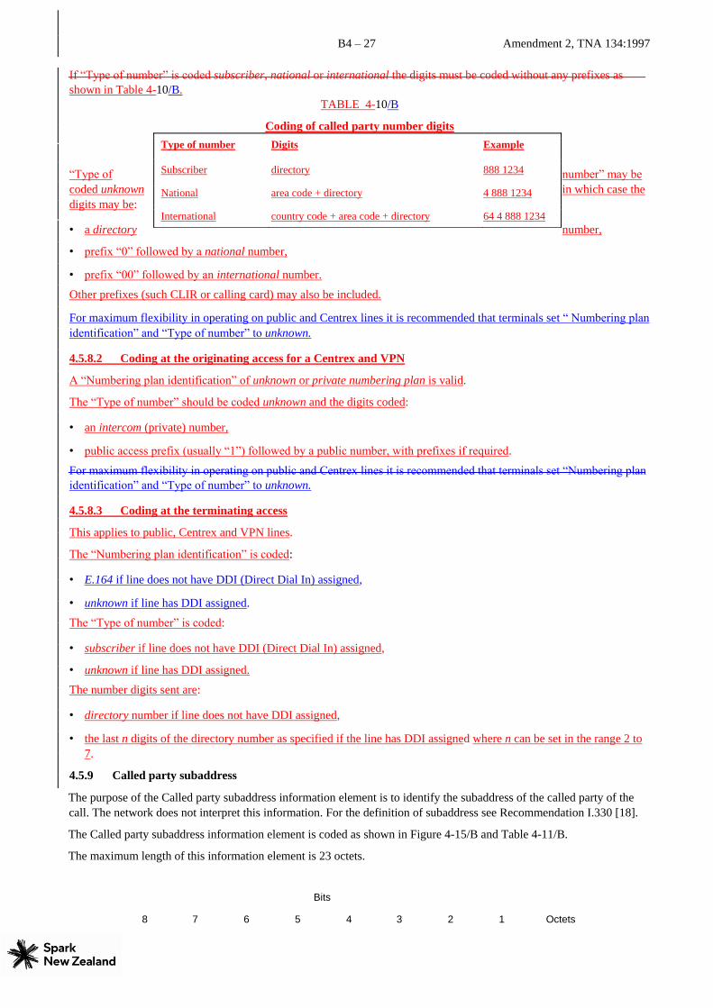
If “Type of number” is coded subscriber, national or international the digits must be coded without any prefixes as
shown in Table 4-10/B. TABLE 4-10/B
Coding of called party number digits
“Type of number” may be
coded unknown in which case the
digits may be:
• a directory number,
• prefix “0” followed by a national number,
• prefix “00” followed by an international number.
Other prefixes (such CLIR or calling card) may also be included.
For maximum flexibility in operating on public and Centrex lines it is recommended that terminals set “ Numbering plan
identification” and “Type of number” to unknown.
4.5.8.2 Coding at the originating access for a Centrex and VPN
A “Numbering plan identification” of unknown or private numbering plan is valid.
The “Type of number” should be coded unknown and the digits coded:
• an intercom (private) number,
• public access prefix (usually “1”) followed by a public number, with prefixes if required.
For maximum flexibility in operating on public and Centrex lines it is recommended that terminals set “Numbering plan
identification” and “Type of number” to unknown.
4.5.8.3 Coding at the terminating access
This applies to public, Centrex and VPN lines.
The “Numbering plan identification” is coded:
• E.164 if line does not have DDI (Direct Dial In) assigned,
• unknown if line has DDI assigned.
The “Type of number” is coded:
• subscriber if line does not have DDI (Direct Dial In) assigned,
• unknown if line has DDI assigned.
The number digits sent are:
• directory number if line does not have DDI assigned,
• the last n digits of the directory number as specified if the line has DDI assigned where n can be set in the range 2 to
7.
4.5.9 Called party subaddress
The purpose of the Called party subaddress information element is to identify the subaddress of the called party of the
call. The network does not interpret this information. For the definition of subaddress see Recommendation I.330 [18].
The Called party subaddress information element is coded as shown in Figure 4-15/B and Table 4-11/B.
The maximum length of this information element is 23 octets.
Bits
8 7 6 5 4 3 2 1 Octets
Type of number Digits Example
Subscriber directory 888 1234
National area code + directory 4 888 1234
International country code + area code + directory 64 4 888 1234

B4 – 28 Amendment 2, TNA 134:1997
1
2
3
4 etc.
FIGURE 4-15/B
Called party subaddress information element
Called party subaddress
0 1 1 1 0 0 0 0
Information element identifier
Length of called party subaddress contents
1 ext. Type of subaddress Odd/even indicator
0 0 0 Spare
Subaddress information

B4 – 29 Amendment 2, TNA 134:1997
TABLE 4-11/B
Called party subaddress information element
Type of subaddress (octet 3)
Bits
7 6 5
0 0 0 NSAP (CCITT Rec. X.213 [23]/ISO 8348 AD2 [24])
0 1 0 User specified
All other values are reserved.
Odd/even indicator (octet 3)
Bit
4
0 Even number of address signals
1 Odd number of address signals
NOTE 1 – The odd/even indicator is used when the type of subaddress is “user specified” and the coding is BCD.
Subaddress information (octets 4, etc.)
The NSAP X.213/ISO8348AD2 address, shall be formatted as specified by octet 4 which contains the Authority and Format Identifier (AFI). The encoding is made according to the “preferred binary encoding” as defined in CCITT Rec. X.213/ISO 8348 AD2 except when used for Terminal selection at the S interface (see Note 3). For the definition of this type of subaddress, see Recommendation I.334 [25].
For user specified subaddress, this field is encoded according to the user specification, subject to a maximum length of 20 octets. When interworking with X.25 [5] networks BCD coding should be applied.
NOTE 2 – It is recommended that users apply the NSAP subaddress type since this subaddress type allows the use of decimal, binary and IA5 syntaxes in a standardized manner.
NOTE 3 – It is recommended that users apply the Local IDI format (the AFI field coded 50 in BCD) when the subaddress
is used for terminal selection purposes at the S interface. In this case the IA5 character syntax using only digits 0 to 9 shall
be used for the DSP. Each character is then encoded in one octet according to Recommendation T.50/ISO 646, with zero
parity in the most significant position.
4.5.10 Calling party number
The purpose of the Calling party number information element is to identify the origin of a call.
The Calling party number information element is coded as shown in Figure 4-16/B, and Table 4-12/B.
The maximum length of this information element is 21 octets
Bits
8 7 6 5 4 3 2 1 Octets
1
2
3
3a*
4*
FIGURE 4-16/B
Calling party number information element
Calling party number
0 1 1 0 1 1 0
Information element identifier
0
Length of calling party number contents
0/1 ext. Type of number Numbering plan identification
1 ext. Presentation
indicataor 0 0 0
Spare Screening indicator
0 Number digits (IA5 characters)

B4 – 30 Amendment 2, TNA 134:1997
TABLE 4-12/B Calling
party number information element
Type of number (octet 3) (Note 1)
Bits
7 6 5
0 0 0 Unknown (Note 2)
0 0 1 International number (Note 3)
0 1 0 National number (Note 3)
0 1 1 Network specific number (Note 4)
1 0 0 Subscriber number (Note 3)
1 1 0 Abbreviated number (Note 5)
1 1 1 Reserved for extension
All other values are reserved.
NOTE 1 – For the definition of international, national and subscriber number, (see Recommendation I.330 [18]). NOTE 2 – The type of number “unknown” is used when the user or the network has no knowledge of the type of number, e.g. international number, national number, etc. In this case the number digits field is organized according to the network dialling plan; e.g. prefix or escape digits might be present.
NOTE 3 – Prefix or escape digits shall not be included. NOTE 4 – The type of number “network specific number” is used to indicate administration/service number specific to the serving network, e.g. used to access an operator.
NOTE 5 – The support of this code is network dependent. The number provided in this information element presents a shorthand representation of the complete number in the specified numbering plan as supported by the network.
Numbering plan identification (octet 3)
Numbering plan (applies for type of number = 000, 001, 010 and 100)
Bits
4 3 2 1
0 0 0 0 Unknown (Note 6)
0 0 0 1 ISDN/telephony numbering plan (Recommendation E.164 [19])
0 0 1 1 Data numbering plan (Recommendation X.121 [21])
0 1 0 0 Telex numbering plan (Recommendation F.69 [22])
1 0 0 0 National standard numbering plan
1 0 0 1 Private numbering plan
1 1 1 1 Reserved for extension
All other values are reserved.
NOTE 6 – The numbering plan “unknown” is used when the user or network has no knowledge of the numbering plan. In
this case the number digits field is organized according to the network dialling plan. e.g. prefix or escape digits might be
present.
TABLE 4-12/B (concluded)
B4 – 31 Amendment 2, TNA 134:1997
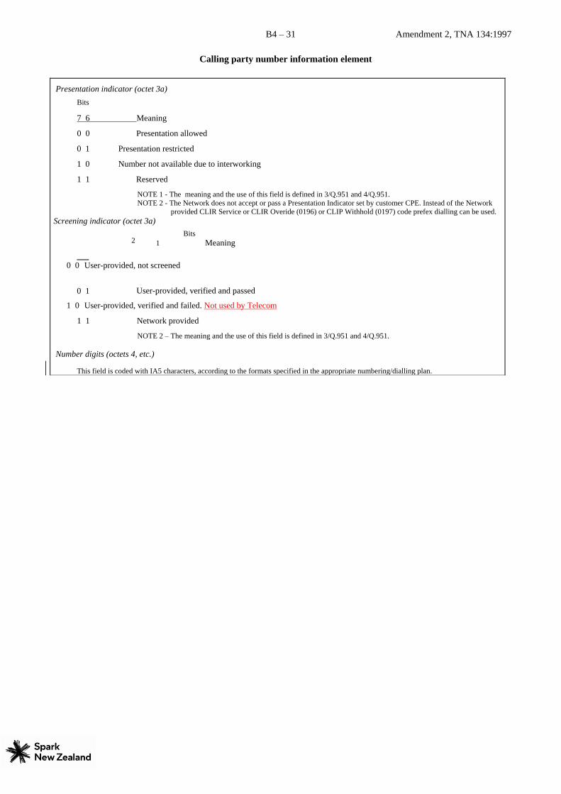
Calling party number information element
Presentation indicator (octet 3a)
Bits
7 6 Meaning
0 0 Presentation allowed
0 1 Presentation restricted
1 0 Number not available due to interworking
1 1 Reserved
NOTE 1 - The meaning and the use of this field is defined in 3/Q.951 and 4/Q.951. NOTE 2 - The Network does not accept or pass a Presentation Indicator set by customer CPE. Instead of the Network
provided CLIR Service or CLIR Overide (0196) or CLIP Withhold (0197) code prefex dialling can be used. Screening indicator (octet 3a)
Bits 1 Meaning
0 0 User-provided, not screened
User-provided, verified and passed
1 0 User-provided, verified and failed. Not used by Telecom
1 1 Network provided
NOTE 2 – The meaning and the use of this field is defined in 3/Q.951 and 4/Q.951.
Number digits (octets 4, etc.)
This field is coded with IA5 characters, according to the formats specified in the appropriate numbering/dialling plan.
0 1
2

B4 – 32 Amendment 2, TNA 134:1997
The Calling party number information element will normally be coded:
Type of Call Numbering plan Type of number Digits
identification
Centrex intercom call unknown unknown intercom number
Public and VPN E.164 National national number
4.5.11 Calling party subaddress
The purpose of the Calling party subaddress information element is to identify a subaddress associated with the origin of
a call. For the definition of subaddress, see Recommendation I.330 [21].
The Calling party subaddress information element is coded as shown in Figure 4-17/B and Table 4-13/B.
The maximum length of this information element is 23 octets.
Bits
8 7 6 5 4 3 2 1 Octets
4.5.10.1 Coding at the originating access
For public, Centrex and VPN lines with or without DDI assigned the subscriber number is passed from the user to the network (currently 7 digits).
The “Numbering plan identification” and “Type of number” should be restricted to :
Numbering plan identification unknown or E.164
r Type of numbe unknown or subscriber
4.5.10.2 Coding at the terminating access
The coding of the Calling party number information element from the network to the user varies depending on the call type. If the call originated in another network (in New Zealand or overseas) the coding will be dependent on the information received from that network .
or E.164 International international numbe r

B4 – 33 Amendment 2, TNA 134:1997
1
2
3
4 etc.
FIGURE 4-17/B
Calling party subaddress information element
Calling party subaddress
0 1 1 0 1 1 0 1 Information element identifier
Length of calling party subaddress contents
1 ext.
Type of subaddress Odd/even indicator
0 0 0 Spare
Subaddress information

B4 – 34 Amendment 2, TNA 134:1997
TABLE 4-13/B Calling
party subaddress information element
Type of subaddress (octet 3) Bits 7 6 5
0 0 0 NSAP(CCITT Rec. X.213 [23]/ISO 8348 AD2 [24]) 0 1 0 User specified
All other values are reserved. Odd/even indicator (octet 3)
Bit 4 0 Even number of address signals 1 Odd number of address signals NOTE 1 – The odd/even indicator is used when the type of subaddress is “user specified” and the coding is BCD.
Subaddress information (octets 4, etc.)
The NSA P CCITT Rec. X.213/ISO 8348 AD2 address, shall be formatted as specified by octet 4 which contains the Authority and Format Identifier (AFI). The encoding is made according to the “preferred binary encoding” as defined in CCITT Rec. X.213/ISO 8348 AD2 except when used for Terminal selection at the S interface (see Note 3). For the definition of this type of subaddress, see Recommendation I.334 [25].
For user specified subaddress, this field is encoded according to the user specification, subject to a maxim um length of 20 octets. When interworking with X.25 [5] networks BCD coding should be applied.
NOTE 2 – It is recommended that users apply the NSAP subaddress type since this subaddress type allows the use of decimal, binary and IA5 syntaxes in a standardized manner.
NOTE 3 – It is recommended that users apply the Local IDI format (the AFI field coded 50 in BCD) when the subaddress is
used for terminal selection purposes at the S interface. In this case the IA5 character syntax using only digits 0 to 9 shall be
used for the DSP. Each character is then encoded in one octet according to CCITT Rec. T.50/ISO 646, with zero parity in
the most significant position.

B4 – 35 Amendment 2, TNA 134:1997
4.5.12 Cause
The content and use of the Cause information element is defined in Recommendation Q.850 [67].
The Cause information element is coded as shown in Figure 4-18/B and Table 4-14/B.
The maximum length of the Cause information element is 2232 octets.
Bits
8 7 6 5 4 3 2 1 Octets
1
2
3
3a*
4
5*
FIGURE 4-18/B
Cause information element
Cause
0 0 0 0 1 0 0
Information element identifier
0
Length of cause contents
0/1 ext. Coding standard 0
spare Location
1 ext. Recommendation (Note 2)
1 ext. Cause value
Diagnostic(s) (if any)
NOTES
1 If the default applies for the Recommendation field, octet including this field shall be omitted.

B4 – 36 Amendment 2, TNA 134:1997
TABLE 4-14/B
Cause information
element
Coding standard (octet 3) Bits 7 6
0 0 CCITT standardized coding, as described below 0 1 ISO/IEC standard (see Note 1) 1 1 national standard (see Note 1)
1 1 standard specific to local interface (see Note 1) Location (octet 3) (Note 2)
Bits 4 3 2 1
0 0 0 0 user (U) 0 0 0 1 private network serving the local user (LPN) 0 0 1 0 public network serving the local user (LN) 0 0 1 1 transit network (TN) 0 1 0 0 public network serving the remote user (RLN) 0 1 0 1 private network serving the remote user (RPN)
0 1 1 1 international network (INTL) 1 0 1 0 network beyond interworking point (BI) All other values are reserved
Recommendation (octet 3a)
Bits 7 6 5 4 3 2 1
0 0 0 0 0 0 0 Q.931 0 0 0 0 0 1 1 X.21 0 0 0 0 1 0 0 X.25 0 0 0 0 1 0 1 public land mobile networks Q.1031/Q.1051
All other values are reserved
Cause (octet 4)
The cause value is divided into two fields, a class (bits 5 through 7) and a value within the class (bits 1 through 4).
1) The class indicates the general nature of the event. Class (000): normal event Class (001): normal event Class (010): resource unavailable Class (011): service or option not available Class (100): service or option not implemented Class (101): invalid message (e.g. parameter out of range)
Class (110): protocol error (e.g. unknown message)
Class (111): interworking
2) The cause values are listed in Table 4-15/B
Diagnostic(s) (octets 5, etc.)
The diagnostics applicable to each cause value are given in Table 4-15/B. Diagnostic information is not available for every cause. In those cases in which the diagnostic is a Q.931 information element, the coding of the diagnostic is the same as for the corresponding information element in 4. Other diagnostic information is defined below.
NOTES 1 - These other coding standards should be used only when the desired cause value cannot be represented with the CCITTstandardized coding.
2 - Location values of ‘0000’ and ‘0101’ received from a user will be passed unchanged to the other user. A
locationvalue of ‘0001’ will be converted to ‘0101’. All other location values will be convert ed to ‘0101’ on primary
rate interfaces and to ‘0000’ on basic rate interfaces.

B4 – 37 Amendment 2, TNA 134:1997
TABLE 4-15/B (sheet 1 of 2)
Cause values
Cause Definition Diagnostics
Class Value No.
000 0001 1 Unallocated (unassigned) number Condition
000 0010 2 No route to specified transit network Transit network identifiy
000 0011 3 No route to destination Condition
000 0110 6 Channel unacceptable
000 0111 7 Call awarded and being delivered in an established
channel
000 1000 8 Preemption
001 0000 16 Normal call clearing Condition
001 0001 17 User busy CCBS Indicator
001 0010 18 No user responding
001 0011 19 No answer from user (user alerted
001 0100 20 Subscriber absent
001 0101 21 Call rejected Call rejected condition
001 0110 22 Number changed New destination
001 1010 26 Non-selected user clearing
001 1011 27 Destination out of order
001 1100 28 Invalid number format (address incomplete)
001 1101 29 Facility rejected Facility Identification
001 1110 30 Response to STATUS ENQUIRY
001 1111 31 Normal, unspecified
010 0010 34 No circuit/Bhannel available
010 0110 38 Network out of order
010 0111 39 Permanent frame mode connection out of service
010 1000 40 Permanent frame mode connection operational
010 1001 41 Temporary failure
010 1010 42 Switching equipment congestion
010 1011 43 Access information discarded Discarded information element
identifier(s) (Note 1)
010 1100 44 Requested circuit/Bhannel not available
010 1110 46 Precedence call blocked
010 1111 47 Resource unavailable, unspecified
011 0001 49 Quality of service unavailable Condition
011 0010 50 Requested facility not subscribed Facility Identification
011 0101 53 Outgoing calls barred within CUG
011 0111 55 Incoming calls barred within CUG
011 1001 57 Bearer capability not authorized Attribute identity
011 1010 58 Bearer capability not presently available Attribute identity
011 1110 62 Inconsistency in designated outgoing access
information and subscriber class

B4 – 38 Amendment 2, TNA 134:1997
011 1111 63 Service or option not available, unspecified
100 0001 65 Bearer capability not implemented Attribute identity
100 0010 66 Channel type not implemented Channel type
100 0101 69 Requested facility not implemented Facility Identification
100 0110 70 Only restricted digital information bearer capability
is available
100 1111 79 Service or option not implemented, unspecified

B4 – 39 Amendment 2, TNA 134:1997
TABLE 4-15/B (sheet 2 of 2)
Cause values Cause Definition Diagnostics
Class Value No
101 0001 81 Invalid call reference value 101 0010 82 Identified channel does not exist Channel identity
101 0011 83 A suspended call exists, but this call identity does
not
101 0100 84 Call identity in use 101 0101 85 No call suspended 101 0110 86 Call having the requested call identity has been
cleared Clearing cause
101 0111 87 User not member of CUG 101 1000 88 Incompatible destination Incompatible parameter
101 1010 90 Non-existent CUG 101 1011 91 Invalid transit network selection 101 1111 95 Invalid message, unspecified 110 0000 96 Mandatory information element is missing Information element identifier
(Note 1)
110 0001 97 Message type non-existent or not implemented Message type
110 0010 98 Message not compatible with call state or message
type non-existent or not implemented Message type
110 0011 99 Information element /parameter non-existent or not
implemented Information element identifier(s)
(Note 1 and Note 2)
110 0100 100 Invalid information element contents Information element identifier(s)
(Note 1)
110 0101 101 Message not compatible with call state Message type
110 0110 102 Recovery on timer expiry Timer number
110 1111 111 Protocol error, unspecified 111 1111 127 Interworking, unspecified
NOTES
1 Locking and non-locking shift procedures described in 4.5/Q.931 are applied. In principle information element identifiers are ordered in the same order as the information element in the received message.
2 When only locking shift information element is included and no variable length information element
identifier follows, it means that the codeset in the locking shift itself is not implemented.
4.5.12.1 Coding of Condition
The condition diagnostic is coded as follows: Bit 8: 1 Bits 7-5: 000
Bit 4: Condition as follows: 0 – Network service –
Provider 1 – Network service – User
Bit 3: Condition as follows:
0 – Normal 1 – Abnormal
Bits 2-1: Condition as follows: 00 – Unknown 01 – Permanent 10 – Transient

B4 – 40 Amendment 2, TNA 134:1997
4.5.12.2 Coding of Transit network identity
The diagnostic field contains the entire transit network selection or network specific facilities information element as
applicable, including parameter name/information element identifier and length octet.
4.5.12.3 Coding of CCBS indicator
The CCBS indicator is coded as follows: Bits 8-1: 00000000 – Spare
00000001 – CCBS possible 00000010 – CCBS not possible 00000011
to – Spare 01111111 10000000 to – Spare for
national use 11111110 11111111 – Reserved for extension
NOTE – Not used in Recommendation Q.931.
4.5.12.4 Coding of Call rejected diagnostic
The format of the diagnostic field for cause number 21 is as shown in Figure 4-19/B and Table 4-16/B.
Octets x*
x+1* etc. (Note 1)
x+2* etc. (Note 2)
NOTES
1 This octet may be present only if octet x indicates user specific diagnostic.
2 This octet may be present only if octet x indicates information element missing or information element contents
are not sufficient.
FIGURE 4-19/B
Coding of diagnostic field for cause number 21
TABLE 4-16/B
Coding of diagnostic field for cause number 21
8 7 6 5 4 3 2 1
1 ext.
Rej ection reason Condition
Us er specific diagnostic
IE type
Information element identifier

B4 – 41 Amendment 2, TNA 134:1997
Rejection reason (octet x)
Bits
7 6 5 4 3 0 0 0 0 0 user specific 0 0 0 0 1 information element missing 0 0 0 1 0 information element contents are not sufficient
All other values are reserved
Condition (octet x)
Bits
unknown 0 1 permanent 1 1 transient
User specific diagnostic (octet x+1) Coded according to the user specification, subject to the maximum length of the Cause information element.
Information element type (octet x+2) Bit
8 0 variable length information element 1 fixed length information element Information element identifier (octet x+2)
Bits 7-1 encoded with the information element identifier of the missing or insufficient information element.
4.5.12.5Coding of New destination/Balled party number (new)
New destination is formatted as the called party number information element, including information element identifier.
Transit network selection may also be included.
4.5.12.6 Coding of Facility identification/Rejected parameter
The coding of facility identification is network dependent.
4.5.12.7 Coding of Attribute identity
The coding of the attribute identity diagnostic is shown in Figure 4-20/B, Tables 4-17/B and 4-18/B.
Octet x x+1 x+2
NOTES
1 When diagnostics
information is provided,
octet x and x+1 shall be
present. Octet x+2 is
optional.
2 Octets x-x+2 may be repeated to report multiple rejected attributes.
3 The extension bit (ext.) when coded 0, indicates that this diagnostic continues to the next octet.
FIGURE 4-20/B
Coding of the diagnostic field for causes number 57, 58 and 65
(Attribute identity)
8 7 6 5 4 3 2 1
0/1 ext. At tribute numb er
0/1 ext. Re jected attribu
te
1 ext. Av ailable attribu
te

B4 – 42 Amendment 2, TNA 134:1997
TABLE 4-17/B
Coding of diagnostic field for causes number 57, 58 and 65 (Attribute identity)
Attribute number (octet x) Bits
7 6 5 4 3 2 1 No.
0 1 1 0 0 0 1 1 Information transfer capability 0 1 1 0 0 1 0 2 Information transfer mode 0 1 1 0 0 1 1 3 Information transfer rate 0 1 1 0 1 0 0 4 Structure 0 1 1 0 1 0 1 5 Configuration 0 1 1 0 1 1 0 6 Establishment 0 1 1 0 1 1 1 7 Symmetry 0 1 1 1 0 0 0 8 Information transfer rate (dest. ® orig.) 0 1 1 1 0 0 1 9 Layer identification
TABLE 4-18/B
Coding of the diagnostic field for causes number 57, 58 and 65 (Attribute identity)
Rejected attribute (octet x+1) Attribute No.
1. Information transfer capability: Bits 7-6: 00 Bits 5-1: according to Table 4-6/B, octet 3
2. Information transfer mode Bits 7-6: according to Table 4-6/B, octet 4
Bits 5-1: 00000
3. Information transfer rate Bits 7-6: 00 Bits 5-1 according to Table 4-6/B, octet 4
4. Layer identification:
Bits 7 6 0 1 (layer 1) Bits 5-1 according to Table 4-6/B, octet 5 1 0 (layer 2) Bits 5-1 according to Table 4-6/B, octet 6 1 1 (layer 3) Bits 5-1 according to Table 4-6/B, octet 7
5. Rate Multiplier: Bit 8: 1 Bits 7-1 according to Table 4-6/B, octet 4.1
Available attributes (octet x+2)
The same coding as octet x+1 4.5.12.8 Coding of Channel type
The channel type is coded as follows:
Bit 8: Extension bit
Bit 7-5: spare
Bit 4-1: according to the Table 4-19/B octet 3.2, channel type.
4.5.12.9 Coding of Incompatible parameter
Incompatible parameter is composed of incompatible information element identifier.
4.5.12.10Coding of Timer number
The timer number is coded in IA5 characters, e.g. T308 is coded as “3” “0” “8”. The following coding is used in each
octet:
Bit 8: Spare “0”
Bit 7-1: IA5 character.

B4 – 43 Amendment 2, TNA 134:1997
4.5.12.11Coding of Message type
Message type is coded as specified in Table Error! Reference source not found..
4.5.13 Channel identification
The purpose of the Channel identification information element is to identify a channel within the interface(s) controlled
by these signalling procedures.
The Channel identification information element is coded as shown in Figures 4-21/B and 4-22/B and Table 4-19/B. The
channel identification element may be repeated in a message, e.g. to list several acceptable channels during channel
negotiation.
The default maximum length for this information element is 3 octets for basic rate interfaces and 9 octets for primary
rate interfaces.
Bits
8 7 6 5 4 3 2 1 Octets
1
2
3
3.1*, etc. (Note 1)
3.2* (Note 2) (Note 5)
3.3* (Note 2) (Note 4) (Note 5)
FIGURE 4-21/B
Channel identification information element
Channel identification
0 0 0 1 1 0 0 0
Information element identifier
Length of channel identification contents
1 ext. Int. id.
present Int. type 0
spare Pref./Excl. D-
channel ind.
Info. channel selection
0/1 ext. Interface identifier
1 ext. Coding standard Number/ Map Channel type/Map element type
Channel number/Slot map (Note 3)
NOTES
1 When the “interface identifier present” field in octet 3 indicates “interface implicitly identified” octet 3.1 is omitted. When octet 3.1 is present it may be extended by using the extension bit (bit 8).
2 When the “interface type” field in octet 3 indicates “basic interface”, octets 3.2 and 3.3 are functionally replaced by the “information channel selection” field in octet 3, and thus omitted.
3 When channel number is used and a single channel is indicated bit 8 shall be set to “1”. When channel number is used and multiple channels are indicated, bit 8 shall be used as an extension bit to indicate an extension to subsequent channels and coded according to the rules specified in 4.5.1.
4 When channel number is used, this octet may be repeated to indicate multiple channels.
5 These octets shall be omitted when the entire interface is to be identified.

B4 – 44 Amendment 2, TNA 134:1997
TABLE 4-19/B Channel
identification information element
Interface identifier present (octet 3) Bit 7 0 Interface implicitly identified (Note 1) 1 Interface explicitly identified in one or more octets, beginning with octet 3.1. Not used on basic rate access.
NOTE 1 – The interface which includes the D-channel carrying this information element is indicated. Interface type (octet 3)
Bit 6 0 Basic interface 1 Other interface e.g. primary rate (Note 2)
NOTE 2 – The type of interface should be understood because the interface is identified by the “interface identifier present”
field (octet 3, bit 7) and the interface identifier field (octet 3.1), if any. Preferred/Exclusive (octet 3)
Bit 4 0 Indicated channel is preferred 1 Exclusive; only the indicated channel is acceptable
NOTE 3 – Preferred/exclusive has significance only for B-channel selection. D-channel indicator (octet 3)
Bit 3 0 The channel identified is not the D-channel 1 The channel identified is the D-channel
NOTE 4 – D-channel indication has significance in D-channel use. No other information affects D-channel use.
Information channel selection (octet 3) (Note 5)
Basic interface Other interfaces
Bits 2 1
0 0 No channel No channel 0 1 B1 channel As indicated in following octets 1 0 B2 channel Reserved
1 1 Any channel (Note 6) Any channel
NOTE 5 – The information channel selection does not apply to the D-channel. NOTE 6 – This value shall be used on a basic access when both B-channels are to be identified, e.g. multirate (64 kbit/s base rate). This shall not be used for restart procedures.
Interface identifier (octet 3.1)
Binary code assigned to the interface at subscription time. At subscription tim e, the binary code for the interface
will specify the number of octets to be used and the content of each octet. Coding standard (octet 3.2)
Bits
7 6
0 0 CCITT standardized coding, as described below
0 1 ISO/IEC standard (Note 7) 1 0 National standard (Note 7)
1 1 Standard defined for the network (either public or private) present on the network side of the interface (Note 1)
NOTE 7 – These other coding standards should only be used when the desired call states cannot be rep resented by
CCITTstandardized coding.

B4 – 45 Amendment 2, TNA 134:1997

B4 – 46 Amendment 2, TNA 134:1997
TABLE 4-19/B (concluded)
Channel identification information element
Number/map (octet 3.2)
Bit
5
0 Channel is indicated by the number in the following octet.
1 Channel is indicated by the slot map (Map) in the following octet(s). Not implemented by Telecom
NOTE 1 – When the information transfer rate is 64 kbit/s the channel number shall be used unless there exists a bilateral agreement between the user and the network to use the slot map.
NOTE 2 – Slot map shall be used when supporting the multirate (64 kbit/s base rate) bearer capability on a primary rate access.
Channel type/map element type (octet 3.2)
Bits
4 3 2 1
0 0 1 1 B-channel units(Note 3)
0 1 1 0 H0-channel units
1 0 0 0 H11-channel units
1 0 0 1 H12-channel units All other values are reserved.
NOTE 3 – This value shall be used for multirate (64 kbit/s base rate) bearer capability.
Channel number (octet 3.3)
Binary number assigned to the channel. For B-channels, the channel number equals the time slot number. See Recommendation I.431 [27]. For B-channels, channel 16 is not available.
NOTE 4 – Either “Channel Number” or “Slot map” is used exclusively, depending on the “Number/Map” information. Slot
map (octet 3.3)
Not implemented by Telecom. Bit position(s) in slot map corresponding to time slot(s) used by the channel is set to 1, see Figure 4-22/B. The remaining bits are set to 0.
NOTE 5 – The length of the slot-map (in bits) is defined by the capacity of the interface type (e.g. 1534 kbit/s or 2048 kbit/s for a primary rate interface) divided by the capacity of the channel type/map-element type (e.g. 64 kbit
/s for a B-channel). The length of the slot map is the smallest number of complete octets that contain the length in bits.
On a Basic rate interface, when Line Hunting applies, the user may specify the configuration at the interface. The options
are Point-to-multipoint, Point-to-point with network control of channels, and Point-to-point with user control of channel
of channels. The fields of the Channel identification information element in the SETUP message sent to the user shall be
coded:
Configuration
Field Point-to-multipoint Point-to-point (Network) Point-to-point (User)
Preferred/exclusive Exclusive Preferred Preferred
Information channel selection B1 or B2 B1 or B2 any
Bits
8 7 6 5 4 3 2 1 Octets
3.3.1
3.3.2
3.3.3
3.3.4
31 30 29 28 27 26 25 24
23 22 21 20 19 18 17 16
15 14 13 12 11 10 9 8
7 6 5 4 3 2 1 0

B4 – 47 Amendment 2, TNA 134:1997
2048 kbit/s
Not available for allocation
a) Primary rate interface, map element type = B channel
Bits
8 7 6 5 4 3 2 1 Octets 3.3 2048 kbit/s
b) Primary rate interface, map element type = H0 channel
NOTE 1 – See Recommendation I.431 [27], Annex A, concerning meaning of a-e.
NOTE 2 – Number within ( ) indicates the associated H 0-channel number used when corresponding H0-channel
is represented by channel number in octet 3.3.
Bits
8 7 6 5 4 3 2 1 Octet
3.3
2048 kbit/s
c) Primary rate interface, map element type = H1-channel
NOTE 3 – Number within ( ) indicates the associated H 1-channel number used when corresponding H1-channel
is represented by channel number in octet 3.3.
NOTE 4 – For 2048 kbit/s interface, H11 slot will be indicated by the same format.
FIGURE 4-22/B
Slot map field
4.5.14 Congestion level
The purpose of the Congestion level information element is to describe the congestion status of the call. Not currently used by Telecom.
e(5) d(4) c(3) b(2) a(1)
H12(1)

B4 – 41 Amendment 2, TNA 134:1997
B4 – 42a
4.5.15 Date/time
The purpose of the Date/time information element is to provide the date and time to the user. It indicates the point in
time when the message has been generated by the network. NOTE – It is a network dependent matter whether the time indicated is local time or Coordinated Universal Time (UTC)
and which calendar is used for referencing the date. The Date/time information will be coded with the local time in New Zealand.
The Date/time information element is coded as shown in Figure4 -22a/B.
Bits
8 7 6 5 4 3 2 1 Octets
1
2
3
4
5
6
7
8
NOTES
1 Octets 3-8
are binary coded
(bit 1 being the least significant bit).
2 Octet 3 is coded with the last two digits of the year. The century must be determined by the terminal.
FIGURE 4-22a/B
Date/time
0 0 1 0 1 0
Information element identifier
0 1
Length of date/time contents
Year
Month
Day
Hour
Minute
Second

B4 – 42 Amendment 2, TNA 134:1997
Date/time information element
2b This page
is intentionally blank

B4 – 43 Amendment 2, TNA 134:1997
4.5.16 Display
The purpose of the Display information element is to supply display information that may be displayed by the user. The
information contained in this element is coded in IA5 characters.
The display information element is coded as shown in Figure 4-23/B.
The Display information element has a network dependent default maximum length of 34 or 82 octets. The evolution to
a single maximum value of 82 octets is an objective. Telecom supports a maximum length of 82 octets. If a user receives
a Display information element with a length exceeding the maximum length which the user can handle, the information
element should be truncated by the user.
Bits
8 7 6 5 4 3 2 1 Octets
1
2
3
etc.
FIGURE 4-23/B
Display information element
4.5.17 High layer compatibility
The purpose of the High layer compatibility information element is to provide a means which should be used by the
remote user for compatibility checking. See Annex B.
The High layer compatibility information element is coded as shown in Figure 4-24/B and Table 4-20/B.
The High layer compatibility information element can be repeated in the SETUP message to indicate dual high layer
capabilities for selection. By default, if the High layer compatibility information element is repeated without the Repeat
indicator information element, it shall be interpreted as increasing order of priority.
The maximum length of this information element is five octets. NOTE – The High layer compatibility information element is transported transparently by an ISDN between a call
originating entity, e.g. a calling user and the addressed entity, e.g. a remote user or a high layer function network node addressed by
the call originating entity. However, if explicitly requested by the user (at subscription time), a network which provides some
capabilities to realize teleservices may interpret this information to provide a particular service.
Display
0 0 1 0 1 0
Information element identifier
0 0
Length of display contents
0 Display information (IA5 characters)

B4 – 44 Amendment 2, TNA 134:1997
Bits
8 7 6 5 4 3 2 1 Octets
1
2
3
4
4a*
(Note)
NOTE – This octet may be
present when octet 4 indicates
Maintenance or Management.
FIGURE 4-24/B
High layer compatibility information element
High layer compatibility
0 1 1 1 1 1 0 1
Information element identifier
Length of high layer compatibility contents
1 ext. Coding standard Interpretation Presentation method of
protocol profile
0/1 ext.
High layer characteristics identification
1 ext. Extended high layer characteristics identification

B4 – 45 Amendment 2, TNA 134:1997
TABLE 4-20/B High layer
compatibility information element
Coding standard (octet 3)
Bits 7 6
0 0 CCITT standardized coding, as described below 0 1 ISO/IEC standard (Note 1) 1 0 National standard (Note 1) 1 1 Standard defined for the network (either public or private) present on
the network side of the interface (Note 1)
NOTE 1 – These other coding standards should only be used only when the desired high layer compatibility cannot be represented by CCITT standardized coding.
Interpretation (octet 3)
Bits
First (primary or only) high layer characteristics identification (in octet 4) to be used in the call All
other values are reserved.
NOTE 2 – “Interpretation” indicates how the “High layer characteristics identifica tion” (in octet 4) should be interpreted.
NOTE 3 – Currently, “Interpretation” has only a single value. However, “Interpretation”, when enhanced, will be able to indicate how the “High layer characteristics identification” in the same information element shall be interpreted when multiple “High layer characteristics identifications” are used and exact relationship among them needs to be indicated (e.g. sequential usage, alternative list, simultaneous usage). Such enhancements in conjunction with the possible negotiation procedures are left for further study.
Presentation method of protocol profile (octet 3)
Bits
High layer protocol profile (without specification of attributes) All other
values are reserved.
NOTE 4 – Currently, “Presentation method of protocol profile” has only a single value, i.e. a “profile value” is used to indicate a service to be supported by high layer protocols as required. Necessity of other presentation methods, e.g. service indications in the forum of layer-by-layer indication of protocols to be used in high layers, is left for further study.
High layer characteristics identification (octet 4)
Bits 7 6 5 4 3 2 1
0 0 0 0 0 0 1 Telephony 0 0 0 0 1 0 0 Facsimile Group 2/3 (Recommendation F.182 [68]) 0 1 0 0 0 0 1 Facsimile Group 4 Class I (Recommendation F.184 [69])
0 1 0 0 1 0 0 Teletex service, basic and mixed mode of operation (Recommendation F.230 [70]) and facsimile service Group 4, Classes II and III (Recommendation F.184)
0 1 0 1 0 0 0 Teletex service, basic and processable mode of operation (Recommendation F.220 [71]) 0 1 1 0 0 0 1 Teletex service, basic mode of operation (Recommendation F.200 [72]) 0 1 1 0 0 1 0 Syntax based Videotex (Recommendations F.300 [73] and T.102 [74])
0 1 1 0 0 1 1 International Videotex interworking via gateways or interworking units (Recommendations F.300 and T.101 [75])
0 1 1 0 1 0 1 Telex service (Recommendation F.60 [76]) 0 1 1 1 0 0 0 Message Handling Systems (MHS) (X.400 - Series Recommendations [77]) 1 0 0 0 0 0 1 OSI application (Note 2) (X.200 - Series Recommendations [78]) 1 0 1 1 1 1 0 Reserved for maintenance (Note
4) 1 0 1 1 1 1 1 Reserved for management (Note
4) 1 1 0 0 0 0 0 Audio visual (Recommendation F.721 [79])
1 1 0 0 0 0 1 through Reserved for audiovisual services (F.700 - Recommandations Series [80])
1 1 0 1 1 1 1 1 1 1 1 1 1 1 Reserved
TABLE 4-20/B (continued)
High layer compatibility information element

B4 – 46 Amendment 2, TNA 134:1997
All other values are reserved.
NOTES
1 The coding above applies in case of “Coding standard” = “CCITT standard” and “Presentation method of
protocol profile” = “High layer protocol profile”. 2 Further compatibility checking will be executed by the OSI high layer protocol. 3 Code points are added only to those services for which CCITT Recommendat ions are available. See also Recommendation I.241 [34].
4 When this coding is included, octet 4 may be followed by octet 4a.
Extended high layer characteristics identification (octet 4a) Bits 7 6 5 4 3 2 1
0 0 0 0 0 0 1 Telephony 0 0 0 0 1 0 0 Facsimile Group 2/3 (Recommendation F.182) 0 1 0 0 0 0 1 Facsimile Group 4 Class I (Recommendation F.184)
0 1 0 0 1 0 0 Teletex service, basic and mixed mode of operation (Recommendation F.230) and facsimile service Group 4, Classes II and III (Recommendation F.184)
0 1 0 1 0 0 0 Teletex service, basic and processable mode of operation (Recommendation F.220) 0 1 1 0 0 0 1 Teletex service, basic mode of operation (Recommendation F.200) 0 1 1 0 0 1 0 Syntax based Videotex (Recommendations F.300 and T.102)
0 1 1 0 0 1 1 International Videotex interworking via gateways or interworking units (Recommendations F.300 and T.101)
0 1 1 0 1 0 1 Telex service (Recommendation F.60) 0 1 1 1 0 0 0 Message Handling Systems (MHS) (X.400 - Series Recommendations) 1 0 0 0 0 0 1 OSI application (Note 2) (X.200 - Series Recommendations)
1 0 1 1 1 1 0 Not available for assignment 1 0 1 1 1 1 1 Not available for assignment 1 1 0 0 0 0 0 Audio visual (Recommendation F.721)
1 1 0 0 0 0 1 through Reserved for audiovisual services (F.700 - Series Recommendations)
1 1 0 1 1 1 1 1 1 1 1 1 1 1 Reserved
All other values are reserved. 4.5.18 Keypad facility
The purpose of the Keypad facility information element is to convey IA5 characters, e.g. entered by means of a
terminal keypad.
The Keypad facility information element is coded as shown in Figure 4-25/B.
The maximum length of this information element is 34 octets.
8 7 6 5 4 3 2 1 Octets
1
2
3 etc.
FIGURE 4-25/B
Keypad facility information element
Keypad facility
0 0 1 0 1 1 0
Information element identifier
0
Length of the keypad facility contents
0 Keypad facility information (IA5 characters)

B4 – 47 Amendment 2, TNA 134:1997
4.5.19 Low layer compatibility
The purpose of the Low layer compatibility information element is to provide a means which should be used for
capability checking by an addressed entity (e.g. a remote user or an interworking unit or a high layer function network
node addressed by the calling user). The Low layer compatibility information element is transferred transparently by
an ISDN between the call originating entity (e.g. the calling user) and the addressed entity. See Annex B and Annex I.
If low layer compatibility negotiation is allowed by the network (see Annex J), the Low layer compatibility information
element is also passed transparently from the addressed entity to originating entity.
The Low layer compatibility information element is coded as shown in Figure 4-26/B and Table 4-21/B. The
maximum length of this information element is 18 octets. Telecom currently supports a maximum length of 16 octets. NOTE – Some networks conforming to Recommendation Q.931 (1988) may support a maximum information element
length of only 16 octets. Telecom currently supports a maximum length of 16 octets.

B4 – 48 Amendment 2, TNA 134:1997
Bits
8 7 6 5 4 3 2 1 Octets
1
2
3
3a*
4
4.1* (Note 1)
5*
5a* (Note 2)
5b* (Note 3)
5b* (Note 4)
5c* (Note 2)
5d* (Note 2)
6*
6a* (Note 5)
6a* (Note 6)
6b* (Note 5)
7*
7a* (Note 7)
7a* (Note 8)
7b* (Note 7)
7c* (Note 7)
FIGURE 4-26/B
Low layer compatibility information element
Low layer compatibility
0 1 1 1 1 1 0
Information element identifier
0
Length of the low layer compatibility contents
0/1 ext. Coding standard Information transfer capability
1 ext. Negot. indic.
0 0 0 0 0 Spare
0
1 ext. Transfer mode Information transfer rate
1 ext. Rate multiplier
0/1 ext. 0 1 Layer 1 ident.
User information layer 1 protocol
0/1 ext. Synch./ asynch.
Negot. User rate
0/1 ext. Intermediate rate NIC on Tx
NIC on Rx
Flow control Flow control 0 Spare
0/1 ext. Hdr/no Hdr
Multiframe Mode Negot. LLI Assignor/ Assignoree
In-band negot. 0 Spare
0/1 ext. Number of stop bits Number of data bits Parity
1 ext. Duplex mode
Modem type
0/1 ext. 1 0 layer 2 ident.
User information layer 2 protocol
0/1 ext. Mode 0 0 0 Spare
Q.933 use
1 ext. User specified layer 2 protocol information
1 ext. Window size (k)
0/1 ext. 1 1 layer 3 ident.
User information layer 3 protocol
0/1 ext. Mode 0 0 0 0 Spare
0
1 ext. Optional layer 3 protocol information
0/1 ext. 0 0 Spare
0 Default packet size
1 ext. Packet window size

B4 – 49 Amendment 2, TNA 134:1997
NOTES to Figure 4-26/B:
1 This octet is required if octet 4 indicates multirate (64 kbit/s base rate). Otherwise, it shall not be present.
2 This octet may be present if octet 3 indicates unrestricted digital information and octet 5 indicates either of the CCITT
standardized rate adaptions V.110 and X.30 or V.120 [9]. It may also be present if octet 3 indicates 3.1 kHz audio and
octet 5 indicates G.711.
3 This octet is significant only if octet 5 indicates CCITT standardized rate adaption (V.110 [7] and X.30 [8]).
4 This octet is significant only if octet 5 indicates CCITT standardized rate adaption V.120 [9].
5 This octet may be present only if octet 6 indicates certain acknowledged mode HDLC elements of procedure as
indicated in Table 4-21/B.
6 This octet may be present only if octet 6 indicates user specified layer 2 protocol.
7 This octet may be present only if octet 7 indicates a layer 3 protocol based on CCITT X.25 | ISO/IEC 8208 or CCITT
Rec. X.223 | ISO 8878 as indicated in Table 4-21/B.
8 This octet may be present only if octet 7 indicates user specified layer 3 protocol.

B4 – 50 Amendment 2, TNA 134:1997
TABLE 4-21/B Low layer
compatibility information element
Coding standard (octet 3)
bits
CCITT standardized coding, as described below 0 1 ISO/IEC standard (Note 1) 1 0 National standard (Note 1) 1 1 Standard defined for the network (either public or private) present on the
network side of the interface (Note 1)
NOTE 1 – These other coding standards should only be used only when the desired low layer compatibility canno t be represented by CCITT-standardized coding.
Information transfer capability (octet 3) Bits 5 4 3 2 1
0 0 0 0 0 Speech 0 1 0 0 0 Unrestricted digital information
0 1 0 0 1 Restricted digital information 1 0 0 0 0 3.1 kHz audio 1 0 0 0 1 Unrestricted digital information with tones/announcements (Note 2) 1 1
0 0 0 Video All other values are reserved. NOTE 2 – Unrestricted digital information with tones/announcements (UDI-TA) is the new information transfer attribute value that had previously been named “7 kHz audio” in Recommendation Q.931 (1988).
Negotiation indicator (octet 3a) Bits 7 0 Out-band negotiation not possible
1 Out-band negotiation possible NOTE 3 – See Annex J for description of low layer compatibility negotiation. NOTE 4 – When octet 3a is omitted, “out-band negotiation not possible” shall be assumed.
Transfer mode (octet 4) Bits
Circuit mode
1 0 Packet-mode All other values are reserved.
Information transfer rate (octet 4) Bits
5 4 3 2 1 Circuit mode Packet-mode 0 0 0 0 0 – This code shall be used for all packet calls 1 0 0 0 0 64 kbit/s –
1 0 0 0 1 2 × 64 kbit/s – 1 0 0 1 1 384 kbit/s – 1 0 1 0 1 1536 kbit/s – 1 0 1 1 1 1920 kbit/s –
1 1 0 0 0 Multirate (64 kbit/s base rate) All other
values are reserved.
NOTE 1 – When the information transfer rate 2 × 64 kbit/s is used the coding of octets 3 and 4 refer to both 64 kbit/s channels. NOTE 2 – Additional attributes are defined in Table 4-22/B.
Rate multiplier (octet 4.1)
Coded as a binary representation of the multiplier to the base r ate. The multiplier can take any value from 2 up to the maximum
number of B-channels available on the interface.

B4 – 51 Amendment 2, TNA 134:1997
TABLE 4-21/B (continued)
Low layer compatibility information element
User information layer 1 protocol (octet 5) Bits 5 4 3 2 1 0 0 0 0 1 CCITT standardized rate adaption V.110 [7] and X.30 [8]. This implies the presence of octet 5a and optionally
octets 5b, 5c and 5d as defined below.
0 0 0 1 0 Recommendation G.711 [10] µ-law. 0 0 0 1 1 Recommendation G.711 A-law. 0 0 1 0 0 Recommendation G.721 [11] 32 kbit/s ADPCM and Recommendation I.460 [15]. 0 0 1 0 1 Recommendations H.221 and H.242.
0 0 1 1 1 Non-CCITT standardized rate adaption. This implies the presence of octet 5a and, optionally, octets 5b,
5c and 5d. The use of this code point indicates that the user rate specified in octet 5a is defined by the user. Additionally, octets 5b, 5c and 5d, if present, are defined consistent with the user specified rate adaption.
0 1 0 0 0 CCITT standardized rate adaption V.120 [9]. This implies the presence of octets 5a and 5b as defined below, and optionally octets 5c and 5d.
0 1 0 0 1 CCITT standardized rate adaption X.31 [14] HDLC flag stuffing. All other values are reserved. NOTE 3 – If the transfer mode is “circuit mode” and if the information transfer capability is “unrestricted digital
information” or “Restricted digital information”, and if a specific user information layer 1 protocol is to be identified to the
addressed entity octet 5 shall be present. If the transfer mode is packet mode, octet 5 may be omitted. Synchronous/Asynchronous
(octet 5a) Bit 7 0 Synchronous data 1 Asynchronous data NOTE 1 – Octets 5b-5d may be omitted in the case of synchronous user rates.
Negotiation (octet 5a) Bit 6
0 In-band negotiation not possible 1 In-band negotiation possible NOTE 2 – See Recommendations V.110 [7] and X.30 [8] or modem type recommendations.
User rate (octet 5a) Bits
5 4 3 2 1 0 0 0 0 0 Rate is indicated by E-bits specified in Recommendation I.460 or may be negotiated in-
band 0 0 0 0 1 0.6 kbit/s Recommendations V.6 [16] and X.1 [17] 0 0 0 1 0 1.2 kbit/s Recommendation V.6
0 0 0 1 1 2.4 kbit/s Recommendations V.6 and
X.1 0 0 1 0 0 3.6 kbit/s Recommendation
V.6 0 0 1 0 1 4.8 kbit/s Recommendations V.6 and X.1 0 0 1 1 0 7.2 kbit/s Recommendation V.6 0 0 1 1 1 8 kbit/s Recommendation I.460 0 1 0 0 0 9.6 kbit/s Recommendations V.6 and X.1
0 1 0 0 1 14.4 kbit/s Recommendation
V.6 0 1 0 1 0 16 kbit/s
Recommendation I.460 0 1 0 1 1 19.2 kbit/s Recommendation V.6 0 1 1 0 0 32 kbit/s Recommendation I.460 0 1 1 1 0 48 kbit/s Recommendations V.6 and X.1
0 1 1 1 1 56 kbit/s Recommendation V.6 1 0 0 0 0 64 kbit/s Recommendation X.1
1 0 1 0 1 0.1345 kbit/s Recommendation X.1 1 0 1 1 0 0.100 kbit/s Recommendation X.1 1 0 1 1 1 0.075/1.2 kbit/s Recommendations V.6 and X.1 (Note 3) 1 1 0 0 0 1.2/0.075 kbit/s Recommendations V.6 and X.1 (Note 3)

B4 – 52 Amendment 2, TNA 134:1997
TABLE 4-21/B (continued)
Low layer compatibility information element
TABLE 4-21/B (continued) Low
layer compatibility information element
1 1 0 0 1 0.050 kbit/s Recommendations V.6 and X.1 1 1 0 1 0 0.075 kbit/s Recommendations V.6 and
X.1 1 1 0 1 1 0.110 kbit/s Recommendations V.6 and
X.1 1 1 1 0 0 0.150 kbit/s Recommendations V.6 and
X.1 1 1 1 0 1 0.200 kbit/s Recommendations V.6 and X.1
1 1 1 1 0 0.300 kbit/s Recommendations V.6 and X.1 1 1
1 1 1 12 kbit/s Recommendation V.6 All other values are
reserved.
NOTE 3 – The first rate is the transmit rate in the forward direction of the call. The second rate is the transmit rate in the backward direction of the call.
Octet 5b for V.110 [7] and X.30 [8] rate adaption
Intermediate rate (octet 5b)
Bits
Not used 0 1 8 kbit/s 1 0 16 kbit/s
1 1 32 kbit/s
Network independent clock (NIC) on transmission (Tx) (octet 5b) (Note 1)
Bit 5 0 Not required to send data with network independent clock
1 Required to send data with network independent clock
NOTE 1 – Refers to transmission in the forward direction of the call. NOTE 2 – See Recommendations V.110 and X.30.
Network independent clock (NIC) on reception (Rx) (octet 5b) (Note 3)
Bit 4 0 Cannot accept data with Network Independent Clock (i.e. sender does not support this optional procedure) 1
Can accept data with Network Independent Clock (i.e. sender does support this optional procedure)
NOTE 3 – Refers to transmission in the backward direction of the call. NOTE 4 – See Recommendations V.110 [7] and X.30 [8].
Flow control on transmission (Tx) (octet 5b) (Note 5)
Bit 3 0 Not required to send data with flow control mechanism
1 Required to send data with flow control mechanism
NOTE 5 – Refers to transmission in the forward direction of the call. NOTE 6 – See Recommendations V.110 and X.30.
Flow control on reception (Rx) (octet 5b) (Note 7)
Bit 2 0 Cannot accept data with flow control mechanism (i.e. sender does not support this optional procedure) 1
Can accept data with flow control mechanism (i.e. sender does support this optional procedure)
NOTE 7 – Refers to transmission in the backward direction of the call. NOTE 8 – See Recommendations V.110 and X.30.
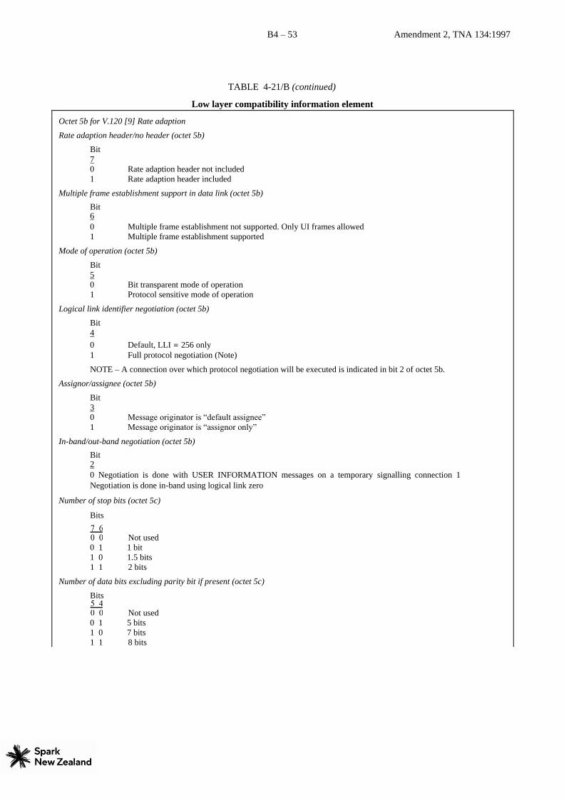
B4 – 53 Amendment 2, TNA 134:1997
TABLE 4-21/B (continued)
Low layer compatibility information element
Octet 5b for V.120 [9] Rate adaption
Rate adaption header/no header (octet 5b)
Bit 7 0 Rate adaption header not included 1 Rate adaption header included
Multiple frame establishment support in data link (octet 5b)
Bit 6 0 Multiple frame establishment not supported. Only UI frames allowed 1 Multiple frame establishment supported
Mode of operation (octet 5b)
Bit 5 0 Bit transparent mode of operation 1 Protocol sensitive mode of operation
Logical link identifier negotiation (octet 5b)
Bit 4 0 Default, LLI = 256 only 1 Full protocol negotiation (Note)
NOTE – A connection over which protocol negotiation will be executed is indicated in bit 2 of octet 5b.
Assignor/assignee (octet 5b)
Bit 3 0 Message originator is “default assignee” 1 Message originator is “assignor only”
In-band/out-band negotiation (octet 5b)
Bit 2 0 Negotiation is done with USER INFORMATION messages on a temporary signalling connection 1
Negotiation is done in-band using logical link zero
Number of stop bits (octet 5c)
Bits
Not used 0 1 1 bit 1 0 1.5 bits
1 1 2 bits
Number of data bits excluding parity bit if present (octet 5c)
Bits
Not used 0 1 5 bits 1 0 7 bits
1 1 8 bits

B4 – 54 Amendment 2, TNA 134:1997
TABLE 4-21/B (continued)
Low layer compatibility information element
Parity information (octet 5c)
Bits
Odd 0 1 0 Even
0 1 1 None 1 0 0 Forced to 0
1 0 1 Forced to 1
All other values are reserved.

B4 – 55 Amendment 2, TNA 134:1997
TABLE 4-21/B (continued)
Low layer compatibility information element
Duplex mode (octet 5d)
Bit 7 0 Half duplex 1 Full duplex
Modem type (octet 5d)
Bits 6 5 4 3 2 1 0 0 0 0 0 0
through National use 0 0 0 1 0 1
0 1 0 0 0 1 Recommendation V.21 0 1 0 0 1 0 Recommendation V.22 0 1 0 0 1 1 Recommendation V.22 bis
0 1 0 1 0 0 Recommendation
V.23 0 1 0 1 0 1 Recommendation
V.26 0 1 0 1 1 0 Recommendation V.26 bis 0 1 0 1 1 1 Recommendation V.26 ter 0 1 1 0 0 0 Recommendation V.27 0 1 1 0 0 1 Recommendation V.27 bis 0 1 1 0 1 0 Recommendation V.27 ter 0 1 1 0 1 1 Recommendation V.29
0 1 1 1 0 0 Recommendation V.32
1 0 0 0 0 0 through National use
1 0 1 1 1 1
1 1 0 0 0 0 through User specified
1 1 1 1 1 1 All other values reserved.
User information layer 2 protocol (octet 6)
Bits 5 4 3 2 1
0 0 0 0 1 Basic mode ISO 1745 [36] 0 0 0 1 0 Recommendation Q.921 (I.441) [3] (Note 4) 0 0 1 1 0 Recommendation X.25 [5], link layer (Notes 1, 4) 0 1 1 1 1 Recommendation X.25 Multilink (Note 4) 0 1 0 0 0 Extended LAPB; for half duplex operation (T.71 [37]) 0 1 0 0 1 HDLC ARM (ISO 4335) [38] (Note 4) 0 1 0 1 0 HDLC NRM (ISO 4335) (Note 4) 0 1 0 1 1 HDLC ABM (ISO 4335) (Note 4) 0 1 1 0 0 LAN logical link control (ISO 8802/2) [39] 0 1 1 0 1 Recommendation X.75 [40]. Single Link Procedure (SLP) (Note 4) 0 1 1 1 0 Recommendation Q.922 [ ] (Note 4)
0 1 1 1 1 Core aspects of Recommendation Q.922 1 0 0 0 0 User specified (Note 2) 1 0 0 0 1 ISO 7776 DTE-DTE operation (Notes 3, 4) All other
values are reserved.
NOTES
1 This Recommendation is compatible with ISO 7776 DTE-DCE operation.
2 When this coding is included, octet 6a will include user coding for the user specified Layer 2
protocol.

B4 – 56 Amendment 2, TNA 134:1997
TABLE 4-21/B (continued)
Low layer compatibility information element
3 This Standard is compatible with Recommendation X.75 modified by the application rules defined in Recommendation T.90.
4 When this coding is included, octets 6a and 6b with CCITT encoding may be included.

B4 – 57 Amendment 2, TNA 134:1997
TABLE 4-21/B (continued)
Low layer compatibility information element
Octet 6a for CCITT codings
Mode of operation (octet 6a)
Bits
Normal mode of operation
1 0 Extended mode of
operation
All other values are reserved.
Q.933 use (octet 6a)
Bits
For use when the coding defined in Recommendation Q.933 is not used
All other values are reserved.
Octet 6a for user protocol
User specified layer 2 protocol information (octet 6a)
The use and coding of octet 6a is according to user defined requirements.
Window size (k) (octet 6b)
Bits 7-1 binary coding of k parameter value in the range from 1 to 127.
User information layer 3 protocol (octet 7)
Bits 5 4 3 2 1
0 0 0 1 0 Recommendation Q.931 (I.451) 0 0 1 1 0 Recommendation X.25, packet layer (Note 2) 0 0 1 1 1 ISO/IEC 8208 [41] (X.25 packet level protocol for data terminal equipment) (Note 2)
0 1 0 0 0 CCITT Rec. X.223 | ISO 8878 [81] (use of ISO/IEC 8208 [41] and Recommendation X.25 to provide the OSI-CONS) (Note 2)
0 1 0 0 1 ISO/IEC 8473 [43] (OSI connectionless mode protocol) 0 1 0 1 0 Recommendation T.70 [32] minimum network layer
0 1 0 1 1 ISO/IEC TR 9577 [82] (Protocol identification in the network layer) 1 0
0 0 0 User specified (Note 1) All other values are reserved.
NOTE 1 – When this coding is included, octet 7a will included user coding for the user specified layer 3 protocol.
NOTE 2 – When this coding is included, octets 7a, 7b and 7c with CCITT encoding may be included.
Octet 7a for CCITT codings
Mode of operation (octet 7a)
Bits
Normal packet sequence numbering
1 0 Extended packet sequence
numbering
All other values are reserved.
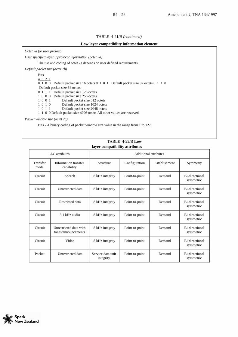
B4 – 58 Amendment 2, TNA 134:1997
TABLE 4-21/B (continued)
Low layer compatibility information element
Octet 7a for user protocol
User specified layer 3 protocol information (octet 7a)
The use and coding of octet 7a depends on user defined requirements.
Default packet size (octet 7b)
Bits 4 3 2 1 0 1 0 0 Default packet size 16 octets 0 1 0 1 Default packet size 32 octets 0 1 1 0
Default packet size 64 octets 0 1 1 1 Default packet size 128 octets 1 0 0 0 Default packet size 256 octets
1 0 0 1 Default packet size 512 octets 1 0 1 0 Default packet size 1024 octets 1 0 1 1 Default packet size 2048 octets
1 1 0 0 Default packet size 4096 octets All other values are reserved.
Packet window size (octet 7c)
Bits 7-1 binary coding of packet window size value in the range from 1 to 127.
TABLE 4-22/B Low
layer compatibility attributes
LLC attributes Additional attributes
Transfer
mode Information transfer
capability Structure Configuration Establishment Symmetry
Circuit Speech 8 kHz integrity Point-to-point Demand Bi-directional
symmetric
Circuit Unrestricted data 8 kHz integrity Point-to-point Demand Bi-directional
symmetric
Circuit Restricted data 8 kHz integrity Point-to-point Demand Bi-directional
symmetric
Circuit 3.1 kHz audio 8 kHz integrity Point-to-point Demand Bi-directional
symmetric
Circuit Unrestricted data with
tones/announcements 8 kHz integrity Point-to-point Demand Bi-directional
symmetric
Circuit Video 8 kHz integrity Point-to-point Demand Bi-directional
symmetric
Packet Unrestricted data Service data unit
integrity Point-to-point Demand Bi-directional
symmetric

B4 – 59 Amendment 2, TNA 134:1997
TABLE 4-21/B (continued)
Low layer compatibility information element
NOTES
1 When the information transfer rate 2 × 64 kbit/s is used, 8 kHz integrity with Restricted Differential Time
Delay (RDTD) is offered.
2 When multirate (64 kbit/s base rate) is indicated as the information transfer rate, Time Slot Sequence integrity
shall be provided.
4.5.20 More data
The More data information element is sent by the user to the network in a USER INFORMATION message, and
delivered by the network to the destination user(s) in the corresponding USER INFORMATION message. The presence
of the More data information element indicates to the destination user that another USER INFORMATION message will
follow, containing information belonging to the same block.
Not currently used by Telecom. Therefore, this clause has not been reproduced.
4.5.21 Network-specific facilities
The purpose of the Network-specific facilities information element is to indicate which network facilities are to be
invoked.
Not currently used by Telecom. Therefore, this clause has not been reproduced.
4.5.22 Notification indicator
The purpose of the Notification indicator information element is to indicate information pertaining to a cal, for example,
al supplementary service operating at some other point within that call.
The Notification indicator information element is coded as shown in Figure 4-27/B and Table 4-23/B.
The maximum length of this information element is three octets.
The Notification indicator information element may be repeated in a message.
Bits
8 7 6 5 4 3 2 1 Octets
1
2
3
FIGURE 4-27/B
Notification indicator information element
Notification indicator
0 0 1 0 0 1
Information element identifier
1 1
Length of notification indicator contents
1 ext. Notification description

B4 – 60 Amendment 2, TNA 134:1997
TABLE 4-23/B
Notification indicator information element
Notification description (octet 3)
Bits 7 6 5 4 3 2 1
0 0 0 0 0 0 0 User suspended 0 0 0 0 0 0 1 User resumed
0 0 0 0 0 1 0 Bearer service change. Not currently used by Telecom. 1 0 0 0 0 1 0 Conference established
1 0 0 0 0 1 1 Conference disconnected 1 0 0 0 1 0 0 Other party added 1 0 0 0 1 0 1 Isolated 1 0 0 0 1 1 0 Reattached 1 0 0 0 1 1 1 Other party isolated 1 0 0 1 0 0 0 Other party reattached 1 0 0 1 0 0 1 Other party split 1 0 0 1 0 1 0 Other party disconnected 1 0 0 1 0 1 1 Conference floating 1 1 0 0 0 0 0 Call is a waiting call 1 1 0 1 0 0 0 Diversion activated 1 1 0 1 0 0 1 Reserved for call transfer 1 1 0 1 0 1 0 Reserved for call transfer 1 1 0 1 1 1 0 Reverse charging 1 1 1 1 0 0 1 Remote hold 1 1 1 1 0 1 0 Remote retrieval 1 1 1 1 0 1 1 Call is diverting
All other values are reserved.
NOTE - The additional codepoints are defined for supplementary services. Some code
points may not be implemented at this time but may be added at any time in the future. 4.5.23 Progress indicator
The purpose of the Progress indicator information element is to describe an event which has occurred during the life of a
call. The information element may occur two times in a message.
The Progress indicator information element is coded as shown in Figure 4-28/B and Table 4-24/B.
The maximum length of this information element is four octets.
Bits
8 7 6 5 4 3 2 1 Octets
1
2
3
4
FIGURE 4-28/B
Progress indicator information element TABLE 4-24/B
Progress indicator information element
Progress indicator
0 0 0 1 1 1 1
Information element identifier
1
Length of progress indicator contents
1 ext. Coding
standard 0
Spare Location
1 ext. Progress description

B4 – 61 Amendment 2, TNA 134:1997
Coding standard (octet 3)
Bits
CCITT standardized coding, as described below 0 1 ISO/IEC standard (Note 1) 1 0 National standard
(Note 1) 1 1 Standard specific to identified location (Note 1)
NOTE 1 – These other coding standards should be used only when the desired progress indication can not be represented with the CCITT-standardized coding.
Location (octet 3)
Bits 4 3 2 1
0 0 0 0 User 0 0 0 1 Private network serving the local user 0 0 1 0 Public network serving the local user 0 0 1 1 Transit network (Note 2) 0 1 0 0 Public network serving the remote user
0 1 0 1 Private network serving the remote user 1
0 1 0 Network beyond the interworking point All
other values are reserved.
NOTE 2 – This value may be generated by some networks.
NOTE 3 – Depending on the location of the users, the local public network and remote public network may be the same network.
NOTE 4 - Location values of ‘ 0000’ and ‘0101’ received from a user will be passed unchanged to the othe r user. A location value of ‘0001’ will be converted to ‘0101’. All other location values will be converted to ‘0101’ on primary rate interfaces and to ‘0000’ on basic rate interfaces.
Progress description (octet 4)
Bits 7 6 5 4 3 2 1 No. 0 0 0 0 0 0 1 1. Call is not end-to-end ISDN; further call progress information may be available in-band 0 0 0 0 0 1 0 2. Destination address is non ISDN 0 0 0 0 0 1 1 3. Origination address is non ISDN 0 0 0 0 1 0 0 4. Call has returned to the ISDN 0 0 0 0 1 0 1 5. Interworking has occurred and has resulted in a telecommunication service change (Note 5) 0 0 0 1 0 0 0 8. In-band information or an appropriate pattern is now available.
All other values are reserved.
NOTE 4 – The use of different progress descriptions is further explained in Annex G.
NOTE 5 – This progress description value shall be used only in the case of interworking in a full ISDN environment, e.g.
when bearer capability selection is not supported or when resource or route of the preferred capability is not available. In
case of interworking with a non-ISDN environment a progress description No. 1 shall be used. If the destination address
is non-ISDN, the progress description No. 2 shall be used. This codepoint is not supported. 4.5.24 Repeat indicator
The purpose of the Repeat indicator information element is to indicate how repeated information elements shall be
interpreted, when included in a message. The Repeat indicator information element is included before the first
occurrence of the information element which will be repeated in a message.
Not currently used by Telecom.
4.5.25 Restart indicator
The purpose of the Restart indicator information element is to identify the class of the facility (i.e. channel or interface)
to be restarted.
The Restart indicator information element is coded as shown in Figure 4-29/B and Table 4-25/B.
The maximum length of this information element is three octets.
Bits
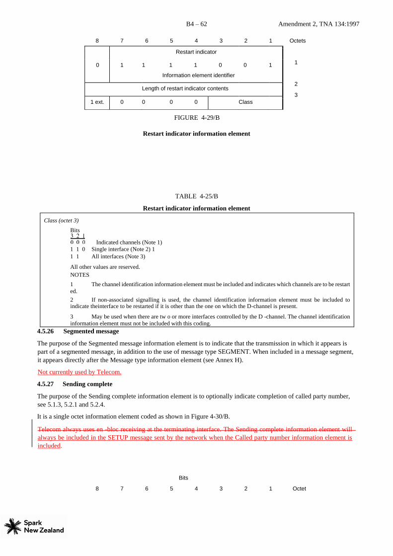
B4 – 62 Amendment 2, TNA 134:1997
8 7 6 5 4 3 2 1 Octets
1
2
3
FIGURE 4-29/B
Restart indicator information element
TABLE 4-25/B
Restart indicator information element
Class (octet 3)
Bits
Indicated channels (Note 1) 1 1 0 Single interface (Note 2) 1
1 1 All interfaces (Note 3)
All other values are reserved. NOTES
1 The channel identification information element must be included and indicates which channels are to be restart
ed. 2 If non-associated signalling is used, the channel identification information element must be included to indicate theinterface to be restarted if it is other than the one on which the D-channel is present.
3 May be used when there are tw o or more interfaces controlled by the D -channel. The channel identification
information element must not be included with this coding. 4.5.26 Segmented message
The purpose of the Segmented message information element is to indicate that the transmission in which it appears is
part of a segmented message, in addition to the use of message type SEGMENT. When included in a message segment,
it appears directly after the Message type information element (see Annex H).
Not currently used by Telecom.
4.5.27 Sending complete
The purpose of the Sending complete information element is to optionally indicate completion of called party number,
see 5.1.3, 5.2.1 and 5.2.4.
It is a single octet information element coded as shown in Figure 4-30/B.
Telecom always uses en -bloc receiving at the terminating interface. The Sending complete information element will
always be included in the SETUP message sent by the network when the Called party number information element is
included.
Bits
8 7 6 5 4 3 2 1 Octet
Restart indicator
0 1 1 1 1 0
Information element identifier
0 1
Length of restart indicator contents
1 ext. 0 0 0 0 Class

B4 – 63 Amendment 2, TNA 134:1997
1
FIGURE 4-30/B
Sending complete information element
4.5.28 Signal
The purpose of the Signal information element is to allow the network to optionally convey information to a user
regarding tones and alerting signals. (See 7).
The Signal information element is coded as shown in Figure 4-31/B and Table 4-26/B.
The length of this information element is three octets.
The Signal information element may be repeated in a message.
The network supplies in-band tones or a Signal information element based ona subscription option. This is always set to
‘network provided tones’. However Ring back tone is generated at the terminating switch and always supplied by the
network, irrespective of the setting of ‘network/user provided tones’.
Bits
8 7 6 5 4 3 2 1 Octets
1
2
3
FIGURE 4-31/B
Signal information element TABLE 4-26/B
Signal information element
Sending complete
1 0 1 0 0 0
Information element identifier
0 1
Signal
0 0 1 1 0 1
Information element identifier
0 0
0 0 0 0 0 0
Length of signal contents
0 1
Signal value

B4 – 64 Amendment 2, TNA 134:1997
Signal value (octet 3)
Bits 8 7 6 5 4 3 2 1
0 0 0 0 0 0 0 0 Dial tone on 0 0 0 0 0 0 0 1 Ring back tone on. Ring back tone will always be provided by the network. 0 0 0 0
0 0 1 0 Intercept tone on 0 0 0 0 0 0 1 1 Network congestion tone on 0 0 0 0 0 1 0 0 Busy tone on 0 0 0 0 0 1 0 1 Confirm tone on 0 0 0 0 0 1 1 0 Answer tone on 0 0 0 0 0 1 1 1 Call waiting tone 0 0 0 0 1 0 0 0 Off-hook warning tone 0 0 0 0 1 0 0 1 Preemption tone on 0 0 1 1 1 1 1 1 Tones off 0 1 0 0 0 0 0 0 Alerting on – pattern 0 (Note 1) 0 1 0 0 0 0 0 1 Alerting on – pattern 1 (Note 1). Distinctive alerting for Centrex intercom calls 0 1 0 0 0 0 1 0 Alerting on – pattern 2 (Note 2). Automatic call back alerting 0 1 0 0 0 0 1 1 Alerting on – pattern 3 (Note 1) 0 1 0 0 0 1 0 0 Alerting on – pattern 4 (Note 1). Reminder tone alerting 0 1 0 0 0 1 0 1 Alerting on – pattern 5 (Note 1) 0 1 0 0 0 1 1 0 Alerting on – pattern 6 (Note 1)
0 1 0 0 0 1 1 1 Alerting on – pattern 7 (Note 1) 0 1 0 0 1 1 1 1 Alerting off
All other values are reserved. NOTES 1 The use of these patterns is network dependent. 2 Used for special/priority alerting.
4.5.29 Transit network selection
The purpose of the Transit network selection information element is to identify one requested transit network. The
Transit network selection information element may be repeated in a message to select a sequence of transit networks
through which a call must pass (see Annex C).
The Transit network selection information element is coded as shown in Figure 4-32/B and Table 4-27/B. The maximum
length of this information element is 6 octets.
Bits
8 7 6 5 4 3 2 1 Octets
1
2
3
4
etc.
FIGURE 4-32/B
Transit network selection information element
TABLE 4-27/B
Transit network selection
0 1 1 1 1 0 0
Information element identifier
0
Length of transit network selection contents
1 ext. Type of network
identification Network identification plan
0 Network identification (IA5 characters)

B4 – 65 Amendment 2, TNA 134:1997
Transit network selection information element
Type of network identification (octet 3)
Bits
User specified. Not currently used by Telecom. 0 1 0 National network identification (Note 1) 0 1 1 International network identification. Not currently used by Telecom.
All other values are reserved.
NOTE 1 – In the case that “type of network identification” is coded as 010, “national network identification”, “national identification plan” is coded according to national specification.
Network identification plan (octet 3)
Bits 4 3 2 1
0 0 0 0 Unknown. Not currently used by Telecom. 0 0 0 1 Carrier Identification Code (Note 2) 0 0 1 1 Data network identification code (Recommendation X.121) [21]. Not currently used by Telecom.
All other values are reserved.
NOTE 2 – Carrier Identification Codes may be an appropriate method of identifying the network serving the remote user.
Network identification (octet 4)
These IA5 characters are organized according to the network identification plan specified in octet 3.
If present this must consist of three octets..
4.5.30 User-user
The purpose of the User-user information element is to convey information between ISDN users. This information is not
interpreted by the network, but rather is carried transparently and delivered to the remote user(s).
The User-user information element is coded as shown in Figure 4-33/B and Table 4-28/B. There are no restrictions on
content of the user information field.
In SETUP, ALERTING, CONNECT, DISCONNECT, RELEASE and RELEASE COMPLETE messages, the User-user
information element has a network dependent maximum size of 35 or 131 octets. The evolution to a single maximum
value is the long term objective; the exact maximum value is the subject of further study. Telecom supports a maximum
length of 131 octets.
In USER INFORMATION messages sent in association with a circuit-mode connection, the User-user information
element has a network dependent maximum size of 35 or 131 octets. For USER INFORMATION messages sent in a
temporary or permanent user-user signalling connection, the user information field contained inside this information
element has a maximum size equal to the maximum size of messages defined in clause 3, that is 260 octets. The USER
INFORMATION message is not currently supported. NOTE – The User-user information element is transported transparently by an ISDN between a call originating entity,
e.g. a calling user and the addressed entity, e.g. a remote user or a high layer function network node addressed by the call originating
entity.
Bits
8 7 6 5 4 3 2 1 Octets

B4 – 66 Amendment 2, TNA 134:1997
1
2
3
4
etc.
FIGURE 4-33/B
User-user information element TABLE 4-28/B
User-user information element
Protocol discriminator (octet 3)
Bits 8 7 6 5 4 3 2 1
0 0 0 0 0 0 0 0 User-specific protocol (Note 1) 0 0 0 0 0 0 0 1 OSI high layer protocols 0 0 0 0 0 0 1 0 X.244 [44] (Note 2) 0 0 0 0 0 0 1 1 Reserved for system management convergence function 0 0 0 0 0 1 0 0 IA5 characters (Note 4) 0 0 0 0 0 1 0 1 X.208 and X.209 coded user information (Note 5) 0 0 0 0 0 1 1 1 Rec. V.120 [9] rate adaption 0 0 0 0 1 0 0 0 Q.931/I.451 user-network call control messages
0 0 0 1 0 0 0 0 Reserved for other network layer or layer 3 protocols, through
Including
Recommendation X.25 [5] (Note 3)
0 0 1 1 1 1 1 1
0 1 0 0 0 0 0 0 National use through
0 1 0 0 1 1 1 1
0 1 0 1 0 0 0 0 Reserved for other network layer or layer 3 through
Protocols, including
Recommendation X.25 (Note 3)
1 1 1 1 1 1 1 0 All other values are reserved.
NOTES
1 The user information is structured according to user needs.
2 The user information is structured according to Recommendation X.244 which specifies the structure of X.25 call user data.
3 These values are reserved to discriminate these protocol discriminators from the first octet of a Recommendation X.25 packet including general format identifier.
4 The user information consists of IA5 characters.
5 The number of X.208 and X.209 components contained in a User-user information element as well as their
semantics and use are user-application dependent and may be subject to other Recommendations. 4.6 Information element for packet communications
The information elements defined below are intended to be used in the support of packet communications as described in
clause 6 and Recommendation X.31 [14].
The use of these information elements for out-of-band call control for packet calls is for further study.
User-user
0 1 1 1 1 1
Information element identifier
1 0
Length of user-user contents
Protocol discriminator
User information
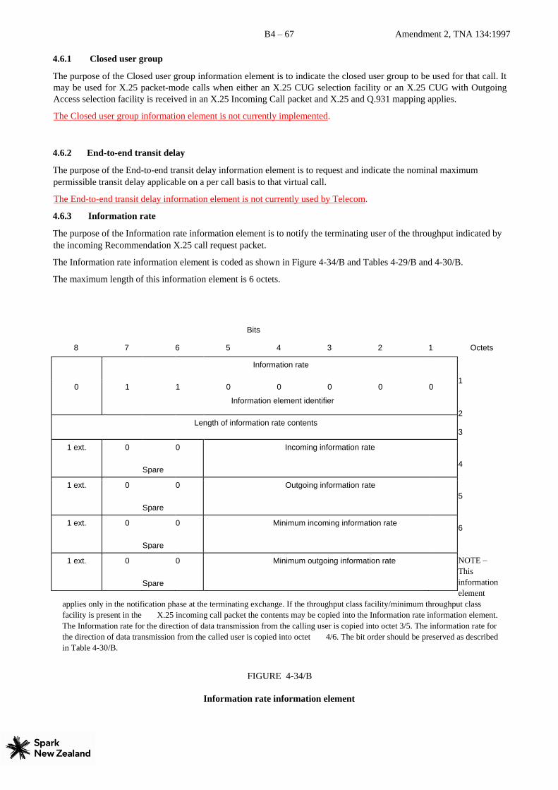
B4 – 67 Amendment 2, TNA 134:1997
4.6.1 Closed user group
The purpose of the Closed user group information element is to indicate the closed user group to be used for that call. It
may be used for X.25 packet-mode calls when either an X.25 CUG selection facility or an X.25 CUG with Outgoing
Access selection facility is received in an X.25 Incoming Call packet and X.25 and Q.931 mapping applies.
The Closed user group information element is not currently implemented.
4.6.2 End-to-end transit delay
The purpose of the End-to-end transit delay information element is to request and indicate the nominal maximum
permissible transit delay applicable on a per call basis to that virtual call.
The End-to-end transit delay information element is not currently used by Telecom.
4.6.3 Information rate
The purpose of the Information rate information element is to notify the terminating user of the throughput indicated by
the incoming Recommendation X.25 call request packet.
The Information rate information element is coded as shown in Figure 4-34/B and Tables 4-29/B and 4-30/B.
The maximum length of this information element is 6 octets.
Bits
8 7 6 5 4 3 2 1 Octets
1
2
3
4
5
6
NOTE –
This
information
element
applies only in the notification phase at the terminating exchange. If the throughput class facility/minimum throughput class
facility is present in the X.25 incoming call packet the contents may be copied into the Information rate information element.
The Information rate for the direction of data transmission from the calling user is copied into octet 3/5. The information rate for
the direction of data transmission from the called user is copied into octet 4/6. The bit order should be preserved as described
in Table 4-30/B.
FIGURE 4-34/B
Information rate information element
Information rate
0 1 1 0 0 0 0
Information element identifier
0
Le ngth of information rate contents
1 ext. 0
Spare
0 Incoming information rate
1 ext. 0
Spare
0 Outgoing information rate
1 ext. 0
Spare
0 Minimum incoming information rate
1 ext. 0
Spare
0 Minimum outgoing information rate
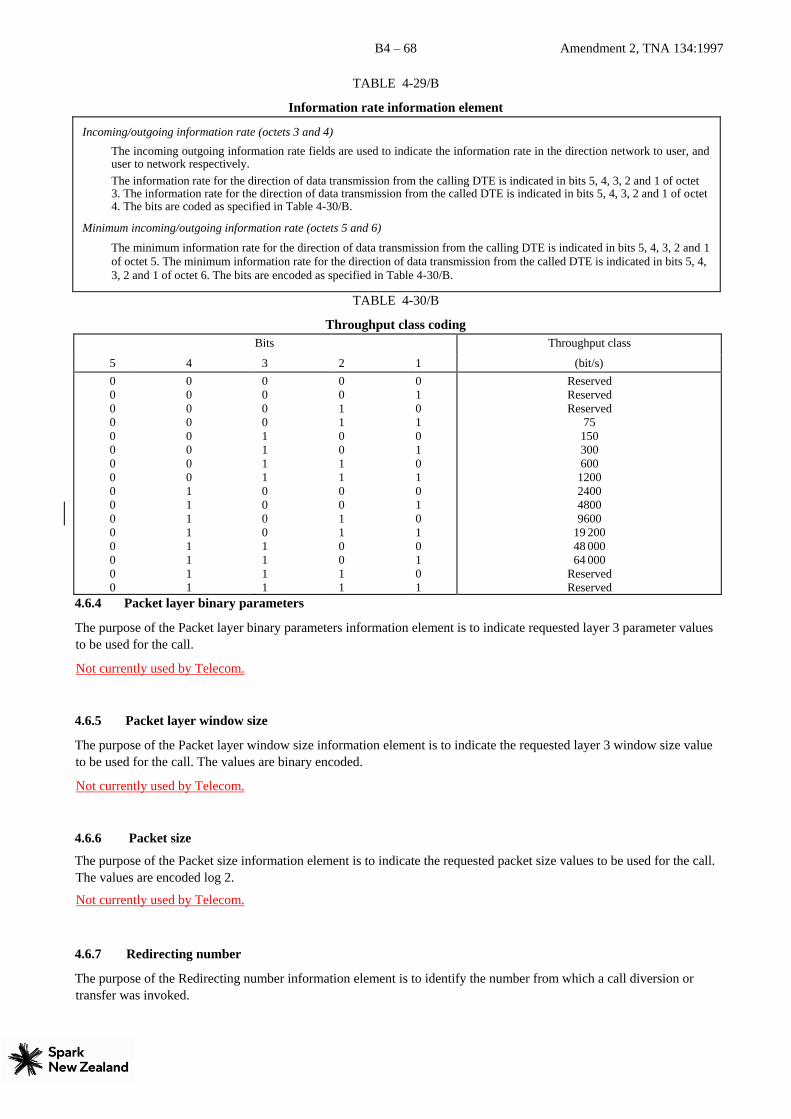
B4 – 68 Amendment 2, TNA 134:1997
TABLE 4-29/B
Information rate information element
Incoming/outgoing information rate (octets 3 and 4)
The incoming outgoing information rate fields are used to indicate the information rate in the direction network to user, and user to network respectively. The information rate for the direction of data transmission from the calling DTE is indicated in bits 5, 4, 3, 2 and 1 of octet 3. The information rate for the direction of data transmission from the called DTE is indicated in bits 5, 4, 3, 2 and 1 of octet 4. The bits are coded as specified in Table 4-30/B.
Minimum incoming/outgoing information rate (octets 5 and 6)
The minimum information rate for the direction of data transmission from the calling DTE is indicated in bits 5, 4, 3, 2 and 1
of octet 5. The minimum information rate for the direction of data transmission from the called DTE is indicated in bits 5, 4,
3, 2 and 1 of octet 6. The bits are encoded as specified in Table 4-30/B.
TABLE 4-30/B
Throughput class coding
Bits Throughput class
5 4 3 2 1 (bit/s) 0 0 0 0 0 0 0 0 0 0 0 0 0 0 0 0
0 0 0 0 0 0 0 0 1 1 1 1 1 1 1 1
0 0 0 0 1 1 1 1 0 0 0 0 1 1 1 1
0 0 1 1 0 0 1 1 0 0 1 1 0 0 1 1
0 1 0 1 0 1 0 1 0 1 0 1 0 1 0 1
Reserved Reserved Reserved
75 150 300 600
1200 2400 4800 9600
19 200 48 000 64 000
Reserved Reserved
4.6.4 Packet layer binary parameters
The purpose of the Packet layer binary parameters information element is to indicate requested layer 3 parameter values
to be used for the call.
Not currently used by Telecom.
4.6.5 Packet layer window size
The purpose of the Packet layer window size information element is to indicate the requested layer 3 window size value
to be used for the call. The values are binary encoded.
Not currently used by Telecom.
4.6.6 Packet size
The purpose of the Packet size information element is to indicate the requested packet size values to be used for the call.
The values are encoded log 2.
Not currently used by Telecom.
4.6.7 Redirecting number
The purpose of the Redirecting number information element is to identify the number from which a call diversion or
transfer was invoked.
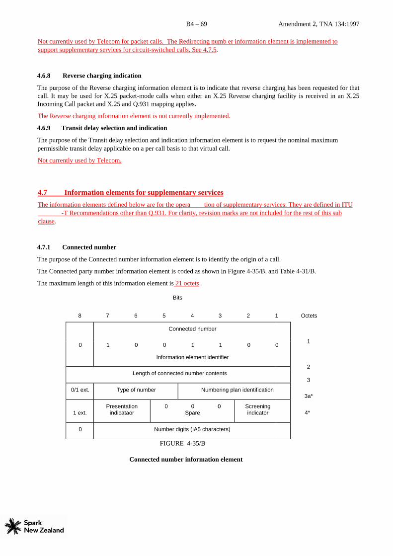
B4 – 69 Amendment 2, TNA 134:1997
Not currently used by Telecom for packet calls. The Redirecting numb er information element is implemented to
support supplementary services for circuit-switched calls. See 4.7.5.
4.6.8 Reverse charging indication
The purpose of the Reverse charging information element is to indicate that reverse charging has been requested for that
call. It may be used for X.25 packet-mode calls when either an X.25 Reverse charging facility is received in an X.25
Incoming Call packet and X.25 and Q.931 mapping applies.
The Reverse charging information element is not currently implemented.
4.6.9 Transit delay selection and indication
The purpose of the Transit delay selection and indication information element is to request the nominal maximum
permissible transit delay applicable on a per call basis to that virtual call.
Not currently used by Telecom.
4.7 Information elements for supplementary services
The information elements defined below are for the opera tion of supplementary services. They are defined in ITU
-T Recommendations other than Q.931. For clarity, revision marks are not included for the rest of this sub
clause.
4.7.1 Connected number
The purpose of the Connected number information element is to identify the origin of a call.
The Connected party number information element is coded as shown in Figure 4-35/B, and Table 4-31/B.
The maximum length of this information element is 21 octets.
Bits
8 7 6 5 4 3 2 1 Octets
1
2
3
3a*
4*
FIGURE 4-35/B
Connected number information element
Connected number
0 1 0 0 1 1 0
Information element identifier
0
Length of connected number contents
0/1 ext. Type of number Numbering plan identification
1 ext. Presentation
indicataor 0 0 0
Spare Screening indicator
0 Number digits (IA5 characters)
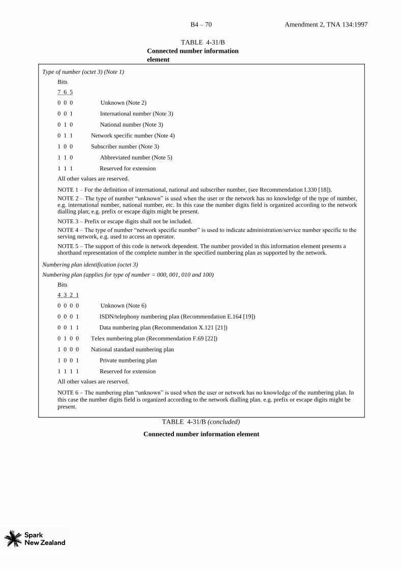
B4 – 70 Amendment 2, TNA 134:1997
TABLE 4-31/B
Connected number information
element
Type of number (octet 3) (Note 1)
Bits
7 6 5
0 0 0 Unknown (Note 2)
0 0 1 International number (Note 3)
0 1 0 National number (Note 3)
0 1 1 Network specific number (Note 4)
1 0 0 Subscriber number (Note 3)
1 1 0 Abbreviated number (Note 5)
1 1 1 Reserved for extension
All other values are reserved.
NOTE 1 – For the definition of international, national and subscriber number, (see Recommendation I.330 [18]). NOTE 2 – The type of number “unknown” is used when the user or the network has no knowledge of the type of number, e.g. international number, national number, etc. In this case the number digits field is organized according to the network dialling plan; e.g. prefix or escape digits might be present.
NOTE 3 – Prefix or escape digits shall not be included. NOTE 4 – The type of number “network specific number” is used to indicate administration/service number specific to the serving network, e.g. used to access an operator.
NOTE 5 – The support of this code is network dependent. The number provided in this information element presents a shorthand representation of the complete number in the specified numbering plan as supported by the network.
Numbering plan identification (octet 3)
Numbering plan (applies for type of number = 000, 001, 010 and 100)
Bits
4 3 2 1
0 0 0 0 Unknown (Note 6)
0 0 0 1 ISDN/telephony numbering plan (Recommendation E.164 [19])
0 0 1 1 Data numbering plan (Recommendation X.121 [21])
0 1 0 0 Telex numbering plan (Recommendation F.69 [22])
1 0 0 0 National standard numbering plan
1 0 0 1 Private numbering plan
1 1 1 1 Reserved for extension
All other values are reserved.
NOTE 6 – The numbering plan “unknown” is used when the user or network has no knowledge of the numbering plan. In
this case the number digits field is organized according to the network dialling plan. e.g. prefix or escape digits might be
present.
TABLE 4-31/B (concluded)
Connected number information element

B4 – 71 Amendment 2, TNA 134:1997
Presentation indicator (octet 3a) Bits
7 6 Meaning
0 0 Presentation allowed
0 1 Presentation restricted
1 0 Number not available due to interworking
1 1 Reserved NOTE 1 – The meaning and the use of this field is defined in 3/Q.951 and 4/Q.951.
Screening indicator (octet 3a) Bits
2 1 Meaning
0 0 User-provided, not screened
0 1 User-provided, verified and passed
1 0 User-provided, verified and failed
1 1 Network provided NOTE 2 – The meaning and the use of this field is defined in 3/Q.951 and 4/Q.951.
Number digits (octets 4, etc.) This field is coded with IA5 characters, according to the formats specified in the appropriate numbering/dialling plan.
4.7.1.1 Coding at the originating interface for public lines
For public and VPN lines the coding of the Connected number information element sent by the network will be
dependent on the coding received from the terminating network (in New Zealand or overseas). Normal coding shall be:
Numbering plan identification E.164 Type of number National or International Digits national or international
4.7.1.2 Coding at the originating interface for Centrex lines
For Centrex and VPN lines the coding of the Connected number information element sent by the network will be: Numbering plan identification Unknown Type of number Unknownl
Digits intercom number 4.7.1.3 Coding at the terminating interface
For public, Centrex and VPN lines the coding of the Connected number sent by the user should be coded: Numbering plan identification unknown or E.164 Type of number unknown or subscriber
Digits subscriber (directory) number 4.7.2 Connected subaddress
The purpose of the Connected subaddress information element is to identify a subaddress associated with the answering
terminal for a call. For the definition of subaddress, see Recommendation I.330 [21].
The Connected subaddress information element is coded as shown in Figure 4-36/B and Table 4-32/B.
The maximum length of this information element is 23 octets.
Bits
8 7 6 5 4 3 2 1 Octets
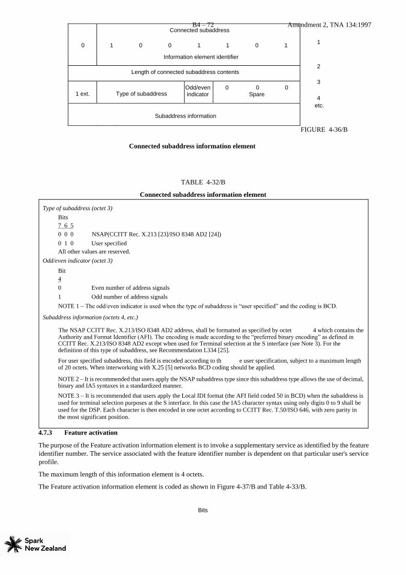
B4 – 72 Amendment 2, TNA 134:1997
1
2
3
4 etc.
FIGURE 4-36/B
Connected subaddress information element
TABLE 4-32/B
Connected subaddress information element
Type of subaddress (octet 3) Bits 7 6 5
0 0 0 NSAP(CCITT Rec. X.213 [23]/ISO 8348 AD2 [24]) 0 1 0 User specified
All other values are reserved. Odd/even indicator (octet 3)
Bit 4 0 Even number of address signals 1 Odd number of address signals NOTE 1 – The odd/even indicator is used when the type of subaddress is “user specified” and the coding is BCD.
Subaddress information (octets 4, etc.)
The NSAP CCITT Rec. X.213/ISO 8348 AD2 address, shall be formatted as specified by octet 4 which contains the Authority and Format Identifier (AFI). The encoding is made according to the “preferred binary encoding” as defined in CCITT Rec. X.213/ISO 8348 AD2 except when used for Terminal selection at the S interface (see Note 3). For the definition of this type of subaddress, see Recommendation I.334 [25].
For user specified subaddress, this field is encoded according to th e user specification, subject to a maximum length of 20 octets. When interworking with X.25 [5] networks BCD coding should be applied.
NOTE 2 – It is recommended that users apply the NSAP subaddress type since this subaddress type allows the use of decimal, binary and IA5 syntaxes in a standardized manner.
NOTE 3 – It is recommended that users apply the Local IDI format (the AFI field coded 50 in BCD) when the subaddress is
used for terminal selection purposes at the S interface. In this case the IA5 character syntax using only digits 0 to 9 shall be
used for the DSP. Each character is then encoded in one octet according to CCITT Rec. T.50/ISO 646, with zero parity in
the most significant position.
4.7.3 Feature activation
The purpose of the Feature activation information element is to invoke a supplementary service as identified by the feature
identifier number. The service associated with the feature identifier number is dependent on that particular user's service
profile.
The maximum length of this information element is 4 octets.
The Feature activation information element is coded as shown in Figure 4-37/B and Table 4-33/B.
Bits
Connected subaddress
0 1 0 0 1 1 0 1
Information element identifier
Length of connected subaddress contents
1 ext.
Type of subaddress Odd/even indicator
0 0 0 Spare
Subaddress information

B4 – 73 Amendment 2, TNA 134:1997
8 7 6 5 4 3 2 1 Octets
1
2
3
3a
FIGURE 4-37/B
Feature activation information element
TABLE 4-33/B
Feature activation information element
Feature identifier number (octets 3 and 3a)
The feature identifier number is a unique number assigned to a feature in a customer account that is coded as part of both the Feature activation and Feature indication information elements. This number identifies the feature that is being requested or updated. The association of a particular number to a particular feature may be different for each user.
Bit 8 in octet 3 is used to extend the feature identifier field. If bit 8 is 0, then another octet follows; if bit 8 is 1, then octet 3 is the last octet. The identifier numbers for a one octet field range from 1 to 127. For a multi-octet field, the order of bit values progressively decreases as the octet number increases.
On public and Centrex lines the following feature activation numbers are defined:
Feature identifier number Meaning
1 Switchhook flash (see Part C, Appendix I for examples of usage)
4.7.4 Information request
The purpose of the Information request information element is to provide the capability for requesting additional
information and signalling completion of the information request.
The Information request information element is coded as shown in Figure 4-38/B and Table 4-34/B.
The default maximum length of the Information request information element is three octets.
Bits
8 7 6 5 4 3 2 1 Octets
1
2
3
FIGURE 4-38/B
Feature activation
0 0 1 1 1 0
Information element identifier
0 0
Length of feature activation contents
0/1 ext.
Feature identifier number
1 ext.
Feature identifier number (continuation)
Information request
0 0 1 1 0 0
Information element identifier
1 0
Length of information request contents
1 ext.
Info. req. ind
Type of information

B4 – 74 Amendment 2, TNA 134:1997
Information request information element
TABLE 4-34/B
Information request information element
Information request indicator (octet 3, bit 7)
Bit 7 – 0 Information request completed 1 Prompt for additional information
Type of information (octet 3, bits 1-6)
Bits 6 5 4 3 2 1 0 0 0 0 0 0 undefined 0 0 0 0 0 1 authorization code 0 0 0 0 1 0 address digits 0 0 0 0 1 1 terminal identification
All other values are reserved.
4.7.5 Redirecting number
The purpose of the Redirecting number information element is to identify the redirecting party of a call.
The Redirecting number information element is coded as shown in Figure 4-39/B, and Table 4-35/B.
The maximum length of this information element is 25 octets
Bits
8 7 6 5 4 3 2 1 Octets
1
2
3
3a*
3b*
4 etc.
FIGURE
4-39/B
Redirecting number information element
TABLE 4-35/B
Redirecting number information element
Redirecting number
0 1 1 1 0 1 0 0
Information element identifier
Length of redirecting number contents
0/1 ext. Type of number Numbering plan identification
0/1 ext. Presentation
indicataor 0 0 0
Spare 0 0
Spare
1 ext. Coding standard for reason for diversion
0 spare Reason for diversion
0 Number digits (IA5 characters)

B4 – 75 Amendment 2, TNA 134:1997
Type of number (octet 3) (Note 1)
Bits
7 6 5
0 0 0 Unknown (Note 2)
0 0 1 International number (Note 3)
0 1 0 National number (Note 3)
0 1 1 Network specific number (Note 4)
1 0 0 Subscriber number (Note 3)
1 1 0 Abbreviated number (Note 5)
1 1 1 Reserved for extension
All other values are reserved.
NOTE 1 – For the definition of international, national and subscriber number, (see Recommendation I.330 [18]). NOTE 2 – The type of number “unknown” is used when the user or the network has no knowledge of the type of number, e.g. international number, national number, etc. In this case the number digits field is organized according to the network dialling plan; e.g. prefix or escape digits might be present.
NOTE 3 – Prefix or escape digits shall not be included. NOTE 4 – The type of number “network specific number” is used to indicate administration/service number specific to the serving network, e.g. used to access an operator.
NOTE 5 – The support of this code is network depen dent. The number provided in this information element presents a
shorthand representation of the complete number in the specified numbering plan as supported by the network.

B4 – 76 Amendment 2, TNA 134:1997
TABLE 4-35/B (concluded)
Redirecting number information element
Numbering plan identification (octet 3)
Numbering plan (applies for type of number = 000, 001, 010 and 100)
Bits
4 3 2 1
0 0 0 0 Unknown (Note 6)
0 0 0 1 ISDN/telephony numbering plan (Recommendation E.164 [19])
0 0 1 1 Data numbering plan (Recommendation X.121 [21])
0 1 0 0 Telex numbering plan (Recommendation F.69 [22])
1 0 0 0 National standard numbering plan
1 0 0 1 Private numbering plan
1 1 1 1 Reserved for extension
All other values are reserved.
NOTE 6 – The numbering plan “unknown” is used when the user or network has no knowledge of the numbering plan. In this case the number digits field is organized according to the network dialling plan. e.g. prefix or escape digits might be present.
Presentation indicator (octet 3a)
Bits
7 6 Meaning
0 0 Presentation allowed
0 1 Presentation restricted
1 0 Number not available due to interworking
1 1 Reserved
NOTE 1 – The meaning and the use of this field is defined in 3/Q.951 and 4/Q.951.
Reason for redirection (octet 3b))
Bits
4 3 2 1
0 0 0 0 Unknown
0 0 0 1 Call forwarding busy or called DTE busy
0 0 1 0 Call forwarding no reply 0 1 0 0 Call deflection
1 0 0 1 Called DTE out of order
1 0 1 0 Call forwarding by the DTE
1 1 1 1 Call forwarding unconditional or systematic call redirection
All other values are reserved. Number digits (octets 4, etc.)
This field is coded with IA5 characters, according to the formats specified in the appropriate numbering/dialling plan.
4.7.5.1 Coding at the terminating interface for public lines
For public and VPN lines the coding of the Redirecting number information element sent by the network will be
dependent on the coding received from the network(s) (in New Zealand or overseas) where the call has been diverted.
Normal coding shall be:
Numbering plan identification E.164 Type of number National or International

B4 – 77 Amendment 2, TNA 134:1997
Digits National or International 4.7.5.2 Coding at the terminating interface for Centrex lines
For Centrex lines, where the diverting line and the terminating line are in the same Centrex group, the coding of the
Redirecting number information element sent by the network for diverting lines within the same Centrex group will be: Numbering plan identification Unknown Type of number Unknown
Digits Intercom number The Redirecting number information element for diverting lines not within the same Centrex group will be coded as
described in 4.7.5.1.


![TNA Montenegro [short]](https://img.pdfslide.us/doc/110x75/5529a7284a795990158b4856/tna-montenegro-short.jpg)