Embed Size (px)
Citation preview

ANSI Z133.1-2006 Safety Requirements for Arboncultural Operations
B.3.2 Emergency Response Procedures Furnish employees with appropriate inforrnation and training necessary to expedite a response to a worksite emergency, such as first aid, CPR, and aerial rescue (see Annex F, Aenal Rescue Flowchart).
B.3.3 Prevention of Back and Other Injuries Provide education and training in the techniques required to avoid back and other injuries ap- plicable to job assignments.
B.3.4 Identification and Avoidance of Animals and Poison Plants Provide education and training in the identification of and the need to avoid contact with poison plants and instructions for treating insect stings/bites and snake bites
B.4 EQUIPMENT SAFETY
B.4.1 Mobile Equipment and Aerial Lifts Provide education and training in the inspection, operation, and maintenance of all vehicles and equipment, such as aerial lifts, brush chippers, stump grinders, log loaders, tree cranes, mowing equipment, and pesticide application equipment All equipment shall comply with applicable federal and state regulations, local ordinances, and manufacturers operating instructions. Such training shall be appropriate to employee job assignments.
B.4.2 Aerial Equipment and Electrical Hazards Provide education and training so that affected employees understand the required and recom-mended procedures for operating aerial devices in proximity to electrical hazards. Such training shall be appropriate to employee job assignments.
B.4.3 Chain Saw, Power Tool, and Hand Tool Use and Safety Provide education and training in the safe use of chain saws, power tools, and hand tools in ac-cordance with manufacturers' instructions. Such training shall be appropriate to employee job assignments.
B.4.4 Climbing Equipment Use and Safety Provide education and training in the inspection, maintenance, and storage of climbing equip-ment such as ropes, saddles, personal lanyards, rope snaps, carabiners, and related equipment. Such training shall be appropriate to employee job assignments.
40 ©2006, International Society of Arbonculture
TNMP 48401_ATM 3-10 ANSI Z133.1-2008.050
Page 100 of 150
ANSI Z133.1-2006 Safety Requtrements for Arboricultural Operations
B.5 OPERATIONAL SAFETY
B.5.1 Climbing Techniques Provide education and training in climbing techniques as appropriate to employee job assignments.
B.5.2 Rigging and Tree Removal B.5.2.1 Provide education and training appropriate to employee job assignments, such
as knots and ropes, ngging techniques, tree strength and weight characteristics, and potential electrical hazards.
B.5.2.2 Provide education and training in the identification and removal of hazard trees. Such training shall be appropriate to employee job assignments.
B.5.3 Hazard Communications Provide education and training necessary to comply with federal and state regulations appropri- ate to employee job assignments.
B.5.4 Pesticide Use Provide education and training necessary to comply with federal and state regulations appropri- ate to employee job assignments.
©2006, Internanonal Sooety of Arbonculture 41
TNMP 48401_ATM 3-10 ANSI Z133.1-2006.051
Page 101 of 150

ANSI Z133 1-2006 Safety Requirements for Arboricultural Operations
ANNEX C (Informative)
General Safety Procedures That Apply to All Tree Work
C.1 LIFTING Before lifting any weight, workers should
(a) be sure there is a clear path available if the weight is to be carried from one place to another;
(b) decide exactly how the object should be grasped to avoid sharp edges, slivers, splinters, or other factors that might cause injury;
(c) make a preliminary lift to be sure the load can be safely handled;
(d) place feet solidly on the walking surface;
(e) crouch as close to the load as possible, with legs bent at an angle of about 90 de-grees;
(f) lift with the legs, not the back, keeping the weight as close to the body as possible; and
(g) use additional workers or material-handling equipment when necessary
C.2 CONTROL OF HAZARDOUS ENERGY When a worker, hereafter referred to as the "authorized person," is doing mechanical work, precautions must taken to prevent injury caused by moving or elevated parts, or the release of stored energy, such as hydraulic pressure. Failure to do so could result in a serious, potentially maiming, or fatal injury The authorized person performing maintenance/repair shall comply with the employer's procedures.
The specific Control of Hazardous Energy requirements established by the Occupational Safety and Health Administration (OSHA) may be obtained by consulting 29 CFR 1910.147 or by writ-ing to the Department of Labor, OSHA, 200 Constitution Avenue NW, Washington, DC 20210.
42 ©2006, International Society of Arbonculture
TNMP 48401_ATM 3-10 ANSI Z133.1-2006.052
Page 102 of 150

ANSI Z133.1-2006 Safety Requirements for Arboncultural Operations
The following is a sample procedure.
Sequence for Securing Equipment (Sample) 1. The authorized person shall notify the crew and/or affected employees that main-
tenance or repair is to be done and that such equipment must be shut down and secured.
2 The authorized person shall refer to the manufacturer's manual for proper proce-dures (as needed).
3. If equipment is in an operational mode, it shall be shut down by normal proce-dures.
4. Rotating parts, such as chipper blades, shall be stopped before maintenance or repair. Keyed ignition systems must be in working order.
5. Keys shall be removed and pocketed by the foreman or mechanic. When there is no keyed ignition system, the battery cables or spark plug wires may be discon-nected.
6. The power takeoff should be disengaged before beginning service or repair tasks, such as hose replacement. Alt hydraulic toots should be disconnected before equip-ment is adjusted or serviced
7 An employee shall never attempt to stop a hydraulic leak with his or her body
8. Materials or parts that must be raised or disconnected and suspended shall be properly secured, such as with an appropriate sling or jackstand. Flywheels, such as chipper cutter heads, are to be blocked to prevent pinch points.
9. Before proceeding with maintenance or repair, the authorized person shall ensure that equipment is isolated and will not operate.
10. Any piece of equipment being serviced or repaired shall not be started, energized, or used by any other worker not under the direction of the authorized person.
11 When the engine must be running for tuning or adjustment, special care must be given to moving parts.
Restoring Equipment to Service (Sample) When maintenance or repair is complete and equipment is ready to return to normal operation, the following steps shall be taken by the authorized person to restore the equipment to service:
1. To prevent accidental contact with moving or electncal components when the equipment is engaged, check for loose parts or tools that may have been left in the immediate area.
2 Ensure that all guards are in place and employees are in the clear.
3. Confiiin that controls are in neutral.
4 Reconnect key, cable, or plug wires.
5. Notify affected employees that equipment is ready to return to service.
©2006, International Society of Arbonculture
43
TNMP 48401_ATM 3-10 ANSI Z133.1-2006.053
Page 103 of 150
ANSI. Z133.1-2006 Safety Requirements for Arboricultural Operations
ANNEX D (Informative)
Additional Resources
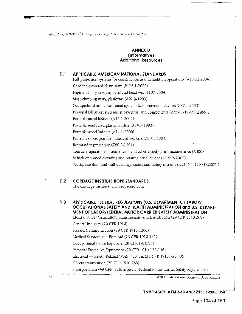
D.1
APPLICABLE AMERICAN NATIONAL STANDARDS Fall protection systems for construction and demolition operations (A10.32-2004)
Gasoline-powered chain saws (B175.1-2000)
High-visibility safety apparel and head wear (107-2004)
Mast-climbing work platforms (A92.9-1993)
Occupational and educational eye and face protection devices (Z87.1-2003)
Personal fall arrest systems, subsystems, and components (Z359.1-1992 ER19991)
Portable metal ladders (A14.2-2002)
Portable reinforced plasuc ladders (A14.5-1992)
Portable wood ladders (A14.1-2000)
Protective headgear for industrial workers (Z89.1-2003)
RespiratOry protection (Z88.2-1991)
Tree care operations—tree, shrub, and other woody plant maintenance (A300)
Vehicle-mounted elevating and rotating aerial devices (A92.2-2002)
Workplace floor and wall openings, stairs, and railing systems (A1264 1-1995 1R20021)
0.2 CORDAGE INSTITUTE ROPE STANDARDS The Cordage Institute, www.ropecord.com
D.3 APPLICABLE FEDERAL REGULATIONS (U.S. DEPARTMENT OF LABOR/ OCCUPATIONAL SAFETY AND HEALTH ADMINISTRATION and U.S. DEPART-MENT OF LABOR/FEDERAL MOTOR CARRIER SAFETY ADMINISTRATION Electric Power Generation, Transmission, and Distribution (29 CFR 1910.269)
General Industry (29 CFR 1910)
Hazard Communication (29 CFR 1915.1200)
Medical Services and First Aid (29 CFR 1910.151)
Occupational Noise Exposure (29 CFR 1910.95)
Personal Protective Equipment (29 CFR 1910.132-136)
Electrical — Safety-Related Work Practices (29 CFR 1910.331-335)
Telecommunication (29 CFR 1910.268)
Transportation (49 CFR, Subchapter B, Federal Motor Carrier Safety Regulations)
44 ©2006, International Society of Arbonculture
TNMP 48401_ATM 3-10 ANSI Z133.1:2006.054 -
Page 104 of 150
ANSI Z133.1-2006 Safety Requirements for Arboncultural Operations
D.4 OTHER RESOURCES
D.4.1 Associations International Society of Arboriculture; PO. Box 3129, Champaign, IL 61826-3129 (www.isa-arbor.com)
Tree Care Industry Association; 3 Perimeter Road, Unit 1, Manchester, NH 03103 (wwwtreecareindustryorg)
D.4.2 Government Agencies National Institute for Occupational Safety and Health/Fatality Assessment and Control Evaluation Program (www.cdc.gov/niosh/face)
Occupational Safety and Health Administration Safety and Health Topics for Tree Care (www.osha.gov/SLTC/treecare)
Occupational Safety and Health Administration Safety and Health Topics for Landscape and Horticultural Services (www.osha.gov/SLTC/landscaping)
©2006, International Society of Arboriculture 45
TNMP 48401_ATM 3-10 ANSI Z133.1-2006.055
Page 105 of 150
ANSI Z133.1-2006 Safety Requirements for Arboncultural Operations
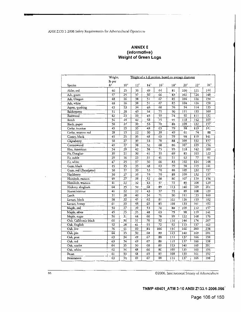
ANNEX E (Informative)
Weight of Green Logs
Weight, lb per
Species ft3 10"
Weight of a 1-ft section, based on average diarneter
24" 12" 14" 16" 18" 20" 22"
Alder, red 46 25 36 49 64 81 100 121 144
Ash, green 47 25 37 50 66 83 102 124 148 Ash, Oregon 48 26 38 51 67 85 104 126 150 Ash, white 48 26 38 51 67 85 104 126 150 Aspen, quaking 43 23 34 46 60 76 94 114 135 Baldcypress 51 28 40 54 71 90 111 135 160 Basswood 42 23 33 45 59 74 92 111 132
Beech 54 29 42 58 75 95 118 142 169
Birch, paper 50 27 39 53 70 88 109 132 157 Cedar, incense 45 25 35 48 63 79 98 119 141 Cedar, western red 28 15 22 30 39 49 61 74 88 Cherry, black 45 25 35 48 63 79 98 119 141 Chinaberry 50 27 39 53 70 88 , 109 132 157 Cottonwood 49 27 38 52 68 86 107 129 154 Elm, American 54 29 42 58 75 95 118 142 169 Fir, Douglas- 39 21 30 41 55 69 85 103 122 Fir, noble 29 16 23 31 41 51 63 77 91 Fir, white 47 25 37 50 66 83 102 124 148 Gurn, black 45 25 35 48 63 79 98 119 141 Gum, red (Eucalyptus) 50 27 39 53 70 88 109 132 157 Hackbcrry 50 27 39 53 70 88 109 132 157 Hemlock, eastern 49 27 38 52 68 86 107 129 154 Hemlock, western 41 22 32 43 57 72 89 108 129 Hickory, shagbark 64 35 50 68 89 113 140 169 201 Horsechestnut 41 22 32 43 57 72 89 108 129 Larch 51 28 40 54 71 90 111 135 160 Locust, black 58 32 45 62 81 102 126 153 182 Locust, honey 61 33 48 65 85 108 133 161 192 Maple, red 50 27 39 53 70 88 109 132 157 Maple, silver 45 25 35 48 63 79 98 119 141 Maple, sugar 56 31 44 60 78 99 122 148 176 Oak, California black 66 36 51 70 92 116 144 174 207 Oak, English 52 28 41 55 72 92 113 137 163 Oak, live 76 41 60 81 106 134 166 200 238 Oak, pin 64 35 50 68 89 113 140 169 201 Oak, post 63 34 49 67 88 111 137 166 198 Oak, red 63 34 49 67 88 111 137 166 198 Oak, scarlet 64 35 50 68 89 113 140 169 201 Oak, white 62 34 48 66 86 109 135 163 194 Pecan 61 33 48 65 85 108 133 161 192 Persimmon 63 34 49 67 88 111 137 166 198
46 ©2006, International Society of Arboriculture
TNMP 48401_ATM 3-10 ANSI Z133.1-2006.056
Page 106 of 150
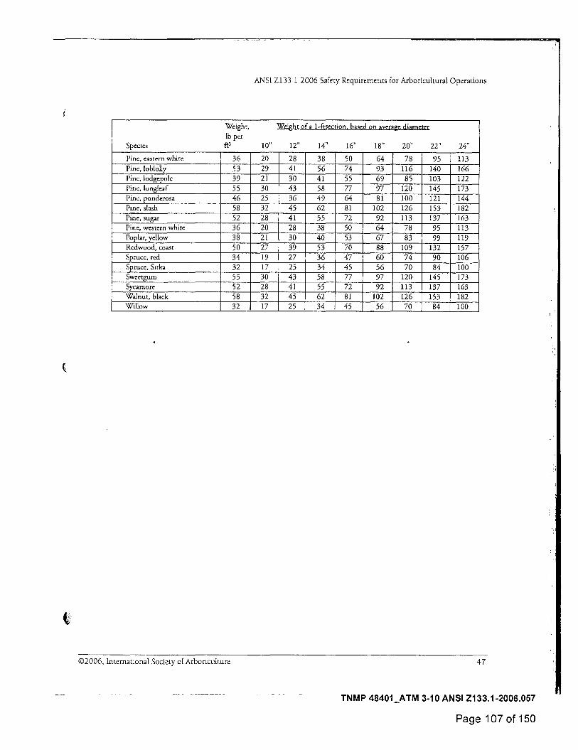
ANSI Z133 1-2006 Safety Requirements for Arboricultural Operations
Weight, lb per
Species ft3
Weight of a 1-ftsection, based on average diameter
24" 10" 12" 14" 16" 18" 20" 22"
Pine, eastern white 36 20 28 38 50 64 78 95 113 Pine, loblolly 53 29 41 56 74 93 116 140 166 Pine, lodgepole 39 21 30 41 55 69 85 103 122 Pine, longleaf 55 30 43 58 77 97 120 145 173 Pine, ponderosa 46 25 36 49 64 81 100 121 144 Ptne, slash 58 32 45 62 81 102 126 153 182 Pine, sugar 52 28 41 55 72 92 113 137 163 Pine, western white 36 20 28 38 50 64 78 95 113 Poplar, yellow 38 21 30 40 53 67 83 99 119 Redwood, coast 50 27 39 53 70 88 109 132 157 Spruce, red 34 19 27 36 47 60 74 90 106 Spruce, Sitka 32 17 25 34 45 56 70 84 100 Sweetgum 55 30 43 58 77 97 120 145 173 Sycamore 52 28 41 55 72 92 113 137 163 Walnut, black 58 32 45 62 81 102 126 153 182 Willow 32 17 25 34 45 56 70 84 100
©2006, International Society of Arboriculture 47
TNMP 48401_ATM 3-10 ANSI Z133.1-2006.057
Page 107 of 150

ANSI Z133.1-2006 Safety Requirements for Arboricultural Operations
ANNEX F (Informative)
Aerial Rescue Flowchart
48 ©2006, International Society of Arboriculture
TNMP 48401_ATM 3-10 ANSI Z133.1-2006.058
Page 108 of 150
Do you suspect a senous neck, back,
or other injury that could be aggravated
moving the victim? Secure the victim
in place; make him Is or her as
comfortable as possible
( here is a victim hurt in a tree or aerial lift
Call 911 / EMS, or have another party call, and stay on the line until 911 / EMS has all
NO* the needed Information Alternately, contact your office and have them summon
assrstance.
YES V
The utility system operator must be contacted, either directly or through
911 / EMS
YES •
Can the electrical hazard be
avokled, eliminated,
or controlled?
Take measures to avoid, eliminate,
or control the electrical hazard.
Secure the area and prepare for EMS.
A
Provide first aid, CPR/resuscitation
as necessary.
NO
Can a rescue be performed without undue risk to the rescuer(s) or
others?
Do you find breathing AND pulse, AND can you rule out
uspension trauma?
Perform Rescue. Bring the victim to
the ground as quickly as possible
NO for CPR/ resuscitation,
even at the risk of aggravating other
injuries.
NON.
Reach the victrm to further assess
hls or her condition
YES
YES
YES
YES
Communicate with the victim to help determine an appropriate rescue
method.
Flowchart Key.
r Start / End Point )
<-'6"ecisoon'> Action
ANSI Z133.1-2006 Safety Requirements for Arboricultural Operations
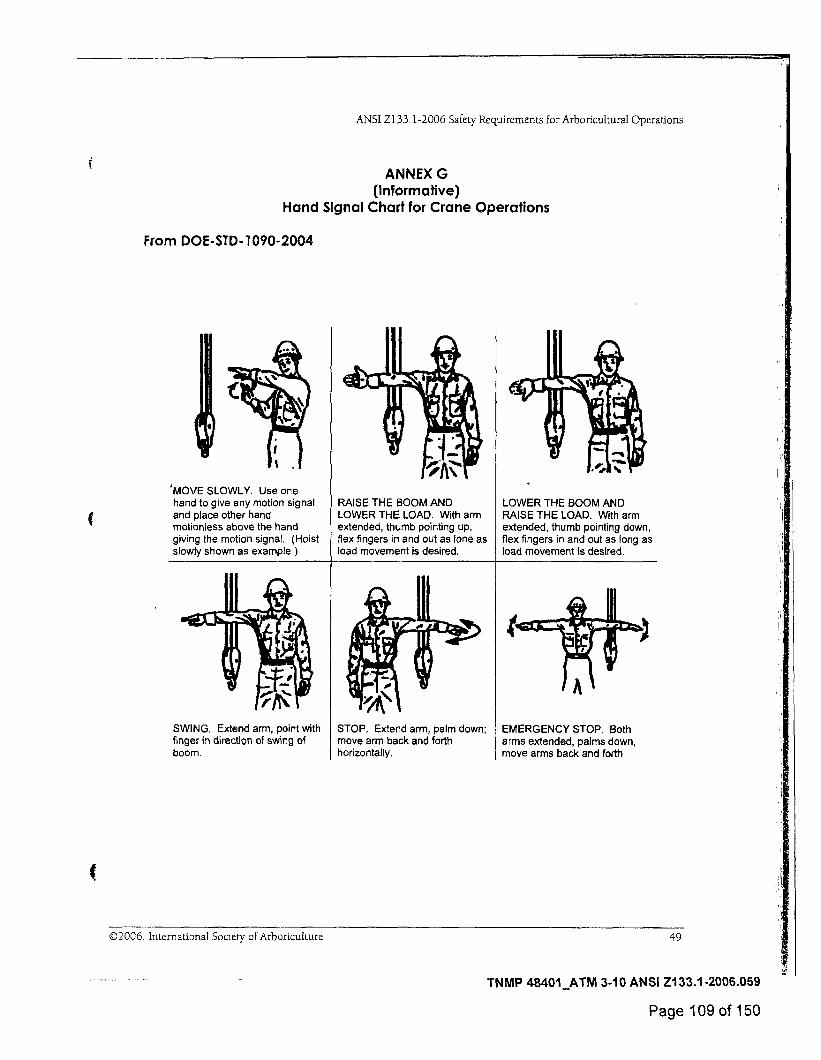
ANNEX G (Informative)
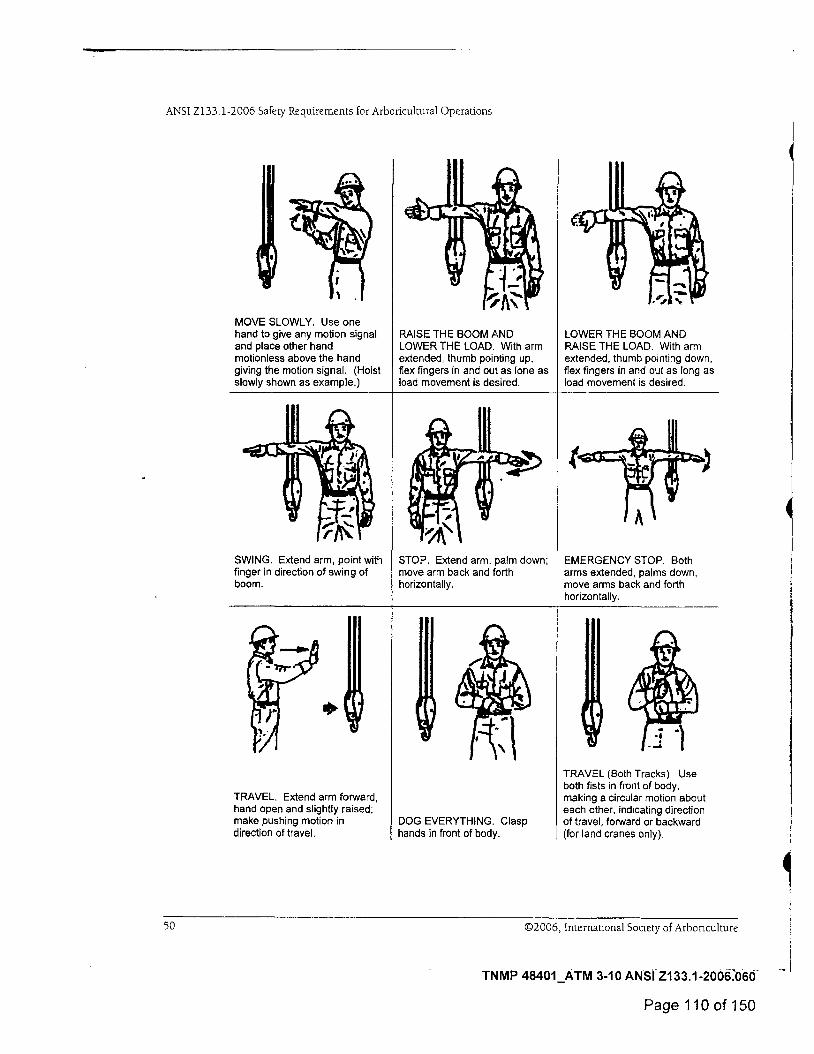
Hand Signal Chart for Crane Operations
From DOE-STD-1090-2004
4MOVE SLOWLY. Use one hand to give any motion signal and place other hand motionless above the hand giving the motion signal. (Hoist slowly shown as example )
RAISE THE BOOM AND LOWER THE LOAD. With arm extended, thumb pointing up, flex fingers in and out as lone as load movement is desired.
LOWER THE BOOM AND RAISE THE LOAD. With arm extended, thumb pointing down, flex fingers in and out as long as load movement is desired.
SWING. Extend arm, point with finger in direction of swing of boom.
STOP. Extend arm, palm down; move arm back and forth horizontally.
EMERGENCY STOP. Both arms extended, palms down, move arms back and forth
©2006, International Society of Arboriculture
49
TNMP 48401_ATM 3-10 ANSI Z133.1-2006.059
Page 109 of 150
ANSI Z133.1-2006 Safety Requirements for Arboricultural Operations
MOVE SLOWLY. Use one hand to give any motion signal and place other hand motionless above the hand giving the motion signal. (Hoist slowly shown as example.)
RAISE THE BOOM AND LOWER THE LOAD. With arm extended, thumb pointing up, flex fingers in and out as lone as load movement is desired.
LOWER THE BOOM AND RAISE THE LOAD. With arm extended, thumb pointing down, flex fingers in and out as long as load movement is desired.
SWING. Extend arm, point with finger in direction of swing of boom.
TRAVEL. Extend arm forward, hand open and slightly raised; make pushing motion in direction of travel.
STOP. Extend arm, palm down; move arm back and forth horizontally.
DOG EVERYTHING. Clasp hands in front of body.
EMERGENCY STOP. Both arms extended, palms down, move arms back and forth horizontally.
TRAVEL (Both Tracks) Use both fists in front of body, making a circular motion about each other, indicating direction of travel, forward or backward (for land cranes only).
50
©2006, International Society of Arbonculture
TNMP 48401_ATM 3-10 ANSI Z133.1-2006060
Page 110 of 150
ANSI Z133.1-2006 Safety Requirements for Arboncultural Operations
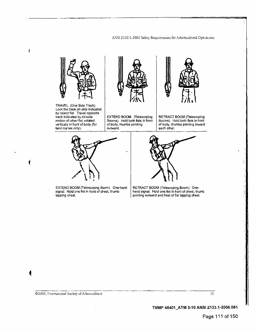
TRAVEL. (One Side Track). Lock the track on side indicated by raised fist. Travel opposite track indicated by circular motion of other fist, rotated vertically in front of body (for land cranes only).
EXTEND BOOM. (Telescoping Booms). Hold both fists in front of body, thumbs pointing outward.
RETRACT BOOM (Telescoping Booms). Hold both fists in front of body, thumbs pointing toward each other.
EXTEND BOOM (Telescoping Boom). One-hand signal. Hold one fist in front of chest, thumb tapping chest.
RETRACT BOOM (Telescoping Boom). One-hand signal. Hold one fist in front of chest, thumb pointing outward and heel of fist tapping chest.
O2006, International Society of Arbonculture 51
TNMP 48401_ATM 3-10 ANSI Z133.1-2006.061
Page 111 of 150
ANSI Z133.1-2006 Safety Requirements for Arboncultural Operations
INDEX
A-C aerial devices, 6, 8-9, 30, 40, 44, 48 American national standards, 39, 44 animals, poisonous, 40 anti-two block devices, 12, 30 apex, 30 apparel
brush removal, 27 contaminated, 4 high visibility, 2 and pesticide application, 29 protective, 3 standards, 44
applicators, 30 arbonsts
definitions, 34 line-clearance, 4-6 training, 38-41
ascenders, 36 axes, 19 back cuts, 26-27, 31 backpack power units, 18 belaymg, 36 booms, 8, 12 branches, 6, 23, 26, 28 bridges, ladder use on, 20 briefings, 2 brush chippers see chippers brush hogs, 14, 31 brush removal, 27-28 buckets, aerial, 8, 9, 31 bucking, 28-29, 31 cables and cabling, 14-15, 23, 26 cant dogs, 18-19 cant hooks, 18-19, 29, 31 carabiners, 20, 21, 31 cardiopulmonary resuscitation (CPR), 3 chain saws
leg protection, 3 for limbing, 28 overview, 17 standards, 44 training and resources, 40 for tree removal, 26 wedges and, 19
chippers, 6, 10 chipping, 27-28 chisels, 19 chopping tools, 19, 31 climbing
secured, 35 techniques, 6, 41 tied in, 35 while rigging, 23-25 work-positioning system, 37
climbing equipment, 20-22, 26, 27, 36, 40 climbing hitch, 22 climbing lines, 13, 30 clothing see apparel communication
from aerial devices, 24 hand signals, 49-51 hazard, 41 telecommunication, 44 using handheld power tools, 16 when climbing, 20, 24 when limbing, 29 when loading, 13 when trimming, 22 when winching, 15
conductors see electrical conductors CPR (cardiopulmonary resuscitation), 3 cranes, 8, 12-14, 34, 49-51 crotches, tree, 22, 23, 31, 32, 36
D-F dbh (diameter at breast height), 36 deadman controls, 14, 31 diameter at breast height (dbh), 36 dielectric capability, 3, 9, 31 drop-starting, 17, 32 electrical cables and cords, 9, 16 electrical conductors
definition, 32 direct contact, 31 guarding, 37 helmets and, 3 indirect contact, 32 minimum approach distance, 5, 33 primary, 34
52
©2006, International Society of Arboriculture
TNMP 48401_ATM 3-10 ANSI Z133.1-2006.062
Page 112 of 150

ANSI Z133 1-2006 Safety Requirements for Arboricultural Operations
INDEX
electrical hazards aenal devices, 9, 40 defined, 32 ladders, 19 overview, 4-7 standards, 44 training and resources, 39
electrical shock, 4 electrical units, 33, 36 emergency procedures, 2-3, 6-7, 39, 40, 48 energy hazards, 42 energy (shock) absorber, 36 equipment care and maintenance, 43 escape routes, tree removal, 26 excavation equipment, 11, 32 eye protection, 3, 10, 11, 19, 44 face protection, 3, 11, 44 false crotches, 22, 23, 32, 36 Federal Motor Carrier Safety Administration, 44
fertilizer application, 11 fire hazards, 23 fire protection, 3-4 first aid, 2, 44 flammable liquids, 3-4 footlock, 37 footwear, 3, 6 fnction point, 37
G-K gas tanks, 9 glossary, 30-37 gloves, 27 gouges, 19 ground fault, 4, 32 hammers, 19 hand signals, 49-51 hand tools, 18-20, 40 handlines, 18, 32 headgear, 2, 3. 44 hearing protection, 3, 10 helmets see headgear hoes, 19 hoists, 7, 8, 9, 12-14 hoses, 9, 11, 35 hydraulic fluids, 9
hydraulic tools, 9, 35, 42 infeed systems, 10, 28 injury prevention, 40, 42 msects, 2 International Society of Arboriculture, 45 jobsite briefing, 39 knots, 20, 31, 35, 37 knucklebooms, 12-14
L-0 ladders
aerial, 8 definition, 33 minimum approach distance, 6 overview, 19-20 standards, 44 tripod-orchard, 20, 36
land clearing, 26, 33 lanyards, 16, 17, 20-21, 33, 35, 36 leg protection, 3, 33 lifting, 42 lifts see hoists limbing, 28-29 hne clearance, 4-5, 6-7, 33, 34, 38-41 loads and loading
capacity, 9 cordage for, 21 overview, 12-13 positioning, 12 while ngging, 24-25 winched, 15 working loads, 23, 36, 37
logs loaders, 12-14 weight of green, 46-47
mauls, 19, 33 minimum approach distance
aerial devices, 9 electrical hazard, 4, 5, 6, 33 hoisting equipment, 12 manual land-cleanng, 26
mobile equipment, 7-8, 40 mowers, 27 muttocks, 19 National Institute for Occupational Safety and Health, 45
©2006, International Society of Arboriculture 53
TNMP 48401_ATM 3-10 ANSI Z133.1-2006.063
Page 113 of 150
ANSI Z133.1-2006 Safety Requirements for Arboricultural Operations
INDEX
noise, 44 notches, 26-27, 31, 33 Occupational Safety and Health Administration (OSHA), 39, 44, 45
off-road operation, 8 off-road vehicles, 14 oil tanks, 9 OSHA (Occupational Safety and Health Administration), 39, 44, 45
outriggers, 8, 33
P-S peaveys, 18-19, 29 personal protective equipment (PPE)
aerial devices, 8 brush chipping, 10 overview, 3 standards, 44 stump cutting, 11 training, 39 while chipping, 27 winching, 14
pesticide application, 11, 29, 41 phase-to-phase, 4 pinch point hazards, 15 plants, poisonous, 2, 40 platforms, 6, 7, 44 pole tools, 18, 22 power tools, 16-18, 40 pruning, 22-23, 38-39 Prusik loops, 21, 34 public safety, 39 pull lines, 26 pulleys, 26, 35 refueling, 3 respiratory protection, 3, 44 rigging, 23-25, 41 rope, 6, 20-22, 26, 44 saddles, 13, 20-21, 30, 35 safety belts, 7 safety requirements, 2 scabbards, 22
septic systems, 9 sheaths, 22 shock-loading, 12 skid-resistant materials, 7, 10, 20 sledges, 19 slopes, ladder use on, 20 snap hooks, 21, 35 splicing, 21 spotters, 7, 35 sprayers, 10-11 step potential, 35 storm work, 6-7 stump cutters, 11
T-W tackle blocks, 26, 35 taglines, 24 termination knots, 20 timber, weight of, 46-47 tongs, 18-19 tools
chopping, 19, 31 hand, 18-20, 40 hydraulic, 9, 35, 42 power, 16-18, 40
towing, 8, 10, 11, 14 tracked vehicles, 14 traffic control, 2, 9, 27, 28, 39 trainees, 34 training, line clearance, 38-41 Tree Care Industry Association, 45 tree removal, 25-27, 41 trimming, 22-23 underground hazards, 9, 11 United States Department of Transportation, 2
vehicles, 7-8, 12 wedges, 19, 26, 29, 36 wheel chocks, 7, 8 winches, 14-15, 28 wood chips, 12 working-load limits, 23 worklines, 20, 36
54
©2006, International Society of Arbonculture
TNMP 48401_ATM 3-10 ANSI Z133:14006.064--
Page 114 of 150
ANSI ZI33.1-2006 Safety Requirements for Arboricultural Operations
Recommendation to ACCREDITED STANDARDS COMMITTEE Z133
STANDARDS FOR ARBORICULTURAL OPERATIONS SECRETARIAT INTERNATIONAL SOCIETY OF ARBORICULTURE
1400 W. ANTHONY DRIVE CHAMPAIGN, IL 61821
Name Date.
Firm, organization, or subgroup
Address
Phone:
Fax.
E-mail.
Sect ion/Raragraph(s)•
Subject/Problem
I recommend that:
Note An recommendations must be in writing Be concise but complete Reference all appropriate page, section, and/or paragraph numbers unless your recommendation is for a new section. State the problem and provide a pos-sible solution, and provide references to any resources that the committee should review in making its determination regarding your recommendation. Attach additional pages if necessary You will receive a written response.
This section for ASC Z133 Secretariat Use Only
Received on By
Presented to Committee on Response sent on By
Passed on Rejected on
Subject for further study
Notes
TNMP 48401_ATM 3-10 ANSI Z133.1-2006.065
Page 115 of 150
ISA wwwisa-arbor.com
TNMP 48401_ATM 3-10 ANSI Z133.1-2006.066
Page 116 of 150
FAC-003-4 Transmission Vegetation Management
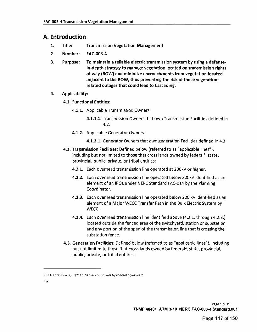
A. Introduction
1. Title: Transmission Vegetation Management
2. Number: FAC-003-4
3. Purpose: To maintain a reliable electric transmission system by using a defense-in-depth strategy to manage vegetation located on transmission rights of way (ROW) and minimize encroachments from vegetation located adjacent to the ROW, thus preventing the risk of those vegetation-related outages that could lead to Cascading.
4. Applicability:
4.1. Functional Entities:
4.1.1. Applicable Transmission Owners
4.1.1.1. Transmission Owners that own Transmission Facilities defined in 4.2.
4.1.2. Applicable Generator Owners
4.1.2.1. Generator Owners that own generation Facilities defined in 4.3.
4.2. Transmission Facilities: Defined below (referred to as "applicable lines),
including but not limited to those that cross lands owned by federall, state, provincial, public, private, or tribal entities:
4.2.1. Each overhead transmission line operated at 200kV or higher.
4.2.2. Each overhead transmission line operated below 200kV identified as an element of an IROL under NERC Standard FAC-014 by the Planning
Coordinator.
4.2.3. Each overhead transmission line operated below 200 kV identified as an
element of a Major WECC Transfer Path in the Bulk Electric System by WECC.
4.2.4. Each overhead transmission line identified above (4.2.1. through 4.2.3.)
located outside the fenced area of the switchyard, station or substation and any portion of the span of the transmission line that is crossing the
substation fence.
4.3. Generation Facilities: Defined below (referred to as "applicable lines"), including
but not limited to those that cross lands owned by federal2, state, provincial, public, private, or tribal entities:
1 EPAct 2005 section 1211c: "Access approvals by Federal agencies."
2 Id.
Page 1 of 31
TNMP 48401_ATM 3-10_NERC FAC-003-4 Standard.001
Page 117 of 150
FAC-003-4 Transmission Vegetation Management
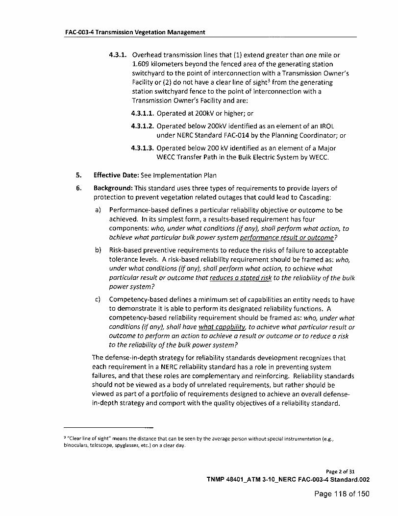
4.3.1. Overhead transmission lines that (1) extend greater than one mile or
1.609 kilometers beyond the fenced area of the generating station switchyard to the point of interconnection with a Transmission Owner's Facility or (2) do not have a clear line of sight3 from the generating station switchyard fence to the point of interconnection with a
Transmission Owner's Facility and are:
4.3.1.1. Operated at 200kV or higher; or
4.3.1.2. Operated below 200kV identified as an element of an IROL
under NERC Standard FAC-014 by the Planning Coordinator; or
4.3.1.3. Operated below 200 kV identified as an element of a Major
WECC Transfer Path in the Bulk Electric System by WECC.
5. Effective Date: See Implementation Plan
6. Background: This standard uses three types of requirements to provide layers of protection to prevent vegetation related outages that could lead to Cascading:
a) Performance-based defines a particular reliability objective or outcome to be
achieved. In its simplest form, a results-based requirement has four components: who, under what conditions (if any), shall perform what action, to
achieve what particular bulk power system performance result or outcome?
b) Risk-based preventive requirements to reduce the risks of failure to acceptable
tolerance levels. A risk-based reliability requirement should be framed as: who, under what conditions (if any), shall perform what action, to achieve what
particular result or outcome that reduces a stated risk to the reliability of the bulk power system?
c) Competency-based defines a minimum set of capabilities an entity needs to have to demonstrate it is able to perform its designated reliability functions. A competency-based reliability requirement should be framed as: who, under what conditions (if any), shall have what capability, to achieve what particular result or
outcome to perform an action to achieve a result or outcome or to reduce a risk to the reliability of the bulk power system?
The defense-in-depth strategy for reliability standards development recognizes that each requirement in a NERC reliability standard has a role in preventing system failures, and that these roles are complementary and reinforcing. Reliability standards should not be viewed as a body of unrelated requirements, but rather should be
viewed as part of a portfolio of requirements designed to achieve an overall defense-in-depth strategy and comport with the quality objectives of a reliability standard.
3 "C I ea r line of sighe means the distance that can be seen by the average person without special instrumentation (e.g.,
binoculars, telescope, spyglasses, etc.) on a clear day.
Page 2 of 31
TNMP 48401_ATM 3-10_NERC FAC-003-4 Standard,002
Page 118 of 150

FAC-003-4 Transmission Vegetation Management
This standard uses a defense-in-depth approach to improve the reliability of the electric Transmission system by:
• Requiring that vegetation be managed to prevent vegetation encroachment inside
the flash-over clearance (R1 and R2);
• Requiring documentation of the maintenance strategies, procedures, processes
and specifications used to manage vegetation to prevent potential flash-over conditions including consideration of 1) conductor dynamics and 2) the
interrelationships between vegetation growth rates, control methods and the
inspection frequency (R3);
• Requiring timely notification to the appropriate control center of vegetation
conditions that could cause a flash-over at any moment (R4);
• Requiring corrective actions to ensure that flash-over distances will not be
violated due to work constrains such as legal injunctions (R5);
• Requiring inspections of vegetation conditions to be performed annually (R6); and
• Requiring that the annual work needed to prevent flash-over is completed (R7).
For this standard, the requirements have been developed as follows:
• Performance-based: Requirements 1 and 2
• Competency-based: Requirement 3
• Risk-based: Requirements 4, 5, 6 and 7
R3 serves as the first line of defense by ensuring that entities understand the problem
they are trying to manage and have fully developed strategies and plans to manage
the problem. R1, R2, and R7 serve as the second line of defense by requiring that
entities carry out their plans and manage vegetation. R6, which requires inspections, may be either a part of the first line of defense (as input into the strategies and plans)
or as a third line of defense (as a check of the first and second lines of defense). R4 serves as the final line of defense, as it addresses cases in which all the other lines of
defense have failed.
Major outages and operational problems have resulted from interference between overgrown vegetation and transmission lines located on many types of lands and ownership situations. Adherence to the standard requirements for applicable lines on any kind of land or easement, whether they are Federal Lands, state or provincial
lands, public or private lands, franchises, easements or lands owned in fee, will reduce and manage this risk. For the purpose of the standard the term "public lands" includes municipal lands, village lands, city lands, and a host of other governmental
entities.
Page 3 of 31
TNMP 48401_ATM 3-10_NERC FAC-003-4 Standard.003
Page 119 of 150

FAC-003-4 Transmission Vegetation Management
This standard addresses vegetation management along applicable overhead lines and
does not apply to underground lines, submarine lines or to line sections inside an
electric station boundary.
This standard focuses on transmission lines to prevent those vegetation related outages that could lead to Cascading. It is not intended to prevent customer outages due to tree contact with lower voltage distribution system lines. For example,
localized customer service might be disrupted if vegetation were to make contact with a 69kV transmission line supplying power to a 12kV distribution station. However, this
standard is not written to address such isolated situations which have little impact on the overall electric transmission system.
Since vegetation growth is constant and always present, unmanaged vegetation poses
an increased outage risk, especially when numerous transmission lines are operating
at or near their Rating. This can present a significant risk of consecutive line failures
when lines are experiencing large sags thereby leading to Cascading. Once the first line fails the shift of the current to the other lines and/or the increasing system loads will lead to the second and subsequent line failures as contact to the vegetation under
those lines occurs. Conversely, most other outage causes (such as trees falling into
lines, lightning, animals, motor vehicles, etc.) are not an interrelated function of the shift of currents or the increasing system loading. These events are not any more likely to occur during heavy system loads than any other time. There is no cause-
effect relationship which creates the probability of simultaneous occurrence of other such events. Therefore these types of events are highly unlikely to cause large-scale
grid failures. Thus, this standard places the highest priority on the management of vegetation to prevent vegetation grow-ins.
B. Requirements and Measures
R1. Each applicable Transmission Owner and applicable Generator Owner shall manage
vegetation to prevent encroachments into the Minimum Vegetation Clearance Distance (MVCD) of its applicable line(s) which are either an element of an IROL, or an
element of a Major WECC Transfer Path; operating within their Rating and all Rated Electrical Operating Conditions of the types shown below4 [Violation Risk Factor: High] [Time Horizon: Real-time]:
4 This requirement does not apply to circumstances that are beyond the control of an applicable Transmission Owner or
applicable Generator Owner subject to this reliability standard, including natural disasters such as earthquakes, fires, tornados, hurricanes, landslides, wind shear, fresh gale, major storms as defined either by the applicable Transmission Owner or
applicable Generator Owner or an applicable regulatory body, ice storms, and floods; human or animal activity such as logging, animal severing tree, vehicle contact with tree, or installation, removal, or digging of vegetation. Nothing in this footnote should be construed to limit the Transmission Owner's or applicable Generator Owner's right to exercise its full legal rights on the ROW.
Page 4 of 31
TNMP 48401_ATM 3-10_NERC FAC-003-4 Standard.004
Page 120 of 150
FAC-003-4 Transmission Vegetation Management
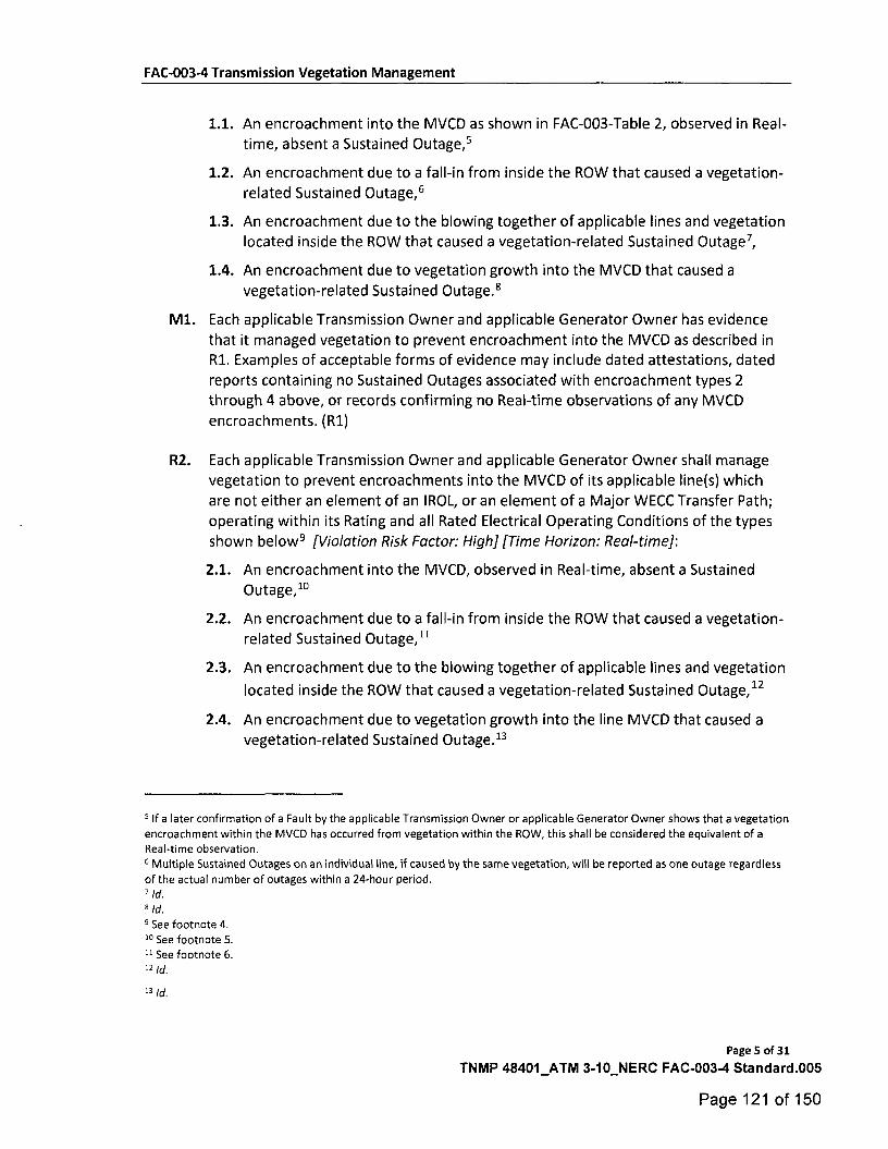
1.1. An encroachment into the MVCD as shown in FAC-003-Table 2, observed in Real-time, absent a Sustained Outage,5
1.2. An encroachment due to a fall-in from inside the ROW that caused a vegetation-related Sustained Outage,6
1.3. An encroachment due to the blowing together of applicable lines and vegetation located inside the ROW that caused a vegetation-related Sustained Outage7,
1.4. An encroachment due to vegetation growth into the MVCD that caused a
vegetation-related Sustained Outage.5
M1. Each applicable Transmission Owner and applicable Generator Owner has evidence
that it managed vegetation to prevent encroachment into the MVCD as described in Rt Examples of acceptable forms of evidence may include dated attestations, dated
reports containing no Sustained Outages associated with encroachment types 2 through 4 above, or records confirming no Real-time observations of any MVCD
encroachments. (R1)
R2. Each applicable Transmission Owner and applicable Generator Owner shall manage vegetation to prevent encroachments into the MVCD of its applicable line(s) which are not either an element of an IROL, or an element of a Major WECC Transfer Path;
operating within its Rating and all Rated Electrical Operating Conditions of the types shown below5 [Violation Risk Factor: High] [Time Horizon: Real-time]:
2.1. An encroachment into the MVCD, observed in Real-time, absent a Sustained Outage,1°
2.2. An encroachment due to a fall-in from inside the ROW that caused a vegetation-
related Sustained Outage,11
2.3. An encroachment due to the blowing together of applicable lines and vegetation
located inside the ROW that caused a vegetation-related Sustained Outage,12
2.4. An encroachment due to vegetation growth into the line MVCD that caused a vegetation-related Sustained Outage.13
5 lf a later confirmation of a Fault by the applicable Transmission Owner or applicable Generator Owner shows that a vegetation
encroachment within the MVCD has occurred from vegetation within the ROW, this shall be considered the equivalent of a
Real-time observation.
6 Multiple Sustained Outages on an individual line, if caused by the same vegetation, will be reported as one outage regardless
of the actual number of outages within a 24-hour period.
7 Id. 8 Id. 9 See footnote 4.
i° See footnote 5.
" See footnote 6. 12 id,
13 Id.
Page 5 of 31
TNMP 48401_ATM 3-10_NERC FAC-003-4 Standard.005
Page 121 of 150
FAC-003-4 Transmission Vegetation Management
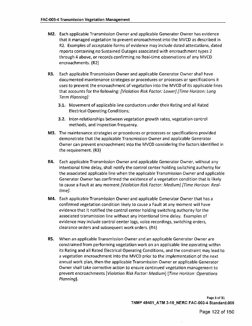
M2. Each applicable Transmission Owner and applicable Generator Owner has evidence
that it managed vegetation to prevent encroachment into the MVCD as described in R2. Examples of acceptable forms of evidence may include dated attestations, dated reports containing no Sustained Outages associated with encroachment types 2
through 4 above, or records confirming no Real-time observations of any MVCD encroachments. (R2)
R3. Each applicable Transmission Owner and applicable Generator Owner shall have documented maintenance strategies or procedures or processes or specifications it
uses to prevent the encroachment of vegetation into the MVCD of its applicable lines
that accounts for the following: [Violation Risk Factor: Lower] [Time Horizon: Long
Term Planning]:
3.1. Movement of applicable line conductors under their Rating and all Rated
Electrical Operating Conditions;
3.2. Inter-relationships between vegetation growth rates, vegetation control methods, and inspection frequency.
M3. The maintenance strategies or procedures or processes or specifications provided demonstrate that the applicable Transmission Owner and applicable Generator Owner can prevent encroachment into the MVCD considering the factors identified in
the requirement. (R3)
R4. Each applicable Transmission Owner and applicable Generator Owner, without any
intentional time delay, shall notify the control center holding switching authority for the associated applicable line when the applicable Transmission Owner and applicable
Generator Owner has confirmed the existence of a vegetation condition that is likely
to cause a Fault at any moment [Violation Risk Factor: Medium] [Time Horizon: Real-
time].
M4. Each applicable Transmission Owner and applicable Generator Owner that has a confirmed vegetation condition likely to cause a Fault at any moment will have evidence that it notified the control center holding switching authority for the
associated transmission line without any intentional time delay. Examples of evidence may include control center logs, voice recordings, switching orders,
clearance orders and subsequent work orders. (R4)
R5. When an applicable Transmission Owner and an applicable Generator Owner are constrained from performing vegetation work on an applicable line operating within its Rating and all Rated Electrical Operating Conditions, and the constraint may lead to a vegetation encroachment into the MVCD prior to the implementation of the next annual work plan, then the applicable Transmission Owner or applicable Generator Owner shall take corrective action to ensure continued vegetation management to prevent encroachments [Violation Risk Factor: Medium] [Time Horizon: Operations Planning].
Page 6 of 31
TNMP 48401_ATM 3-10_NERC FAC-003-4 Standard.006
Page 122 of 150
FAC-003-4 Transmission Vegetation Management
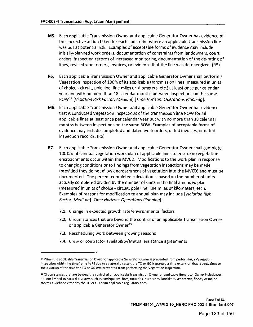
M5. Each applicable Transmission Owner and applicable Generator Owner has evidence of
the corrective action taken for each constraint where an applicable transmission line
was put at potential risk. Examples of acceptable forms of evidence may include
initially-planned work orders, documentation of constraints from landowners, court
orders, inspection records of increased monitoring, documentation of the de-rating of
lines, revised work orders, invoices, or evidence that the line was de-energized. (R5)
R6. Each applicable Transmission Owner and applicable Generator Owner shall perform a
Vegetation Inspection of 100% of its applicable transmission lines (measured in units
of choice - circuit, pole line, line miles or kilometers, etc.) at least once per calendar
year and with no more than 18 calendar months between inspections on the same ROW IA [Violation Risk Factor: Medium] [Time Horizon: Operations Planning].
M6. Each applicable Transmission Owner and applicable Generator Owner has evidence
that it conducted Vegetation Inspections of the transmission line ROW for all applicable lines at least once per calendar year but with no more than 18 calendar months between inspections on the same ROW. Examples of acceptable forms of evidence may include completed and dated work orders, dated invoices, or dated inspection records. (R6)
R7. Each applicable Transmission Owner and applicable Generator Owner shall complete
100% of its annual vegetation work plan of applicable lines to ensure no vegetation encroachments occur within the MVCD. Modifications to the work plan in response
to changing conditions or to findings from vegetation inspections may be made
(provided they do not allow encroachment of vegetation into the MVCD) and must be documented. The percent completed calculation is based on the number of units actually completed divided by the number of units in the final amended plan (measured in units of choice - circuit, pole line, line miles or kilometers, etc.). Examples of reasons for modification to annual plan may include [Violation Risk
Factor: Medium] [Time Horizon: Operations Planning]:
7.1. Change in expected growth rate/environmental factors
7.2. Circumstances that are beyond the control of an applicable Transmission Owner
or applicable Generator Owner15
7.3. Rescheduling work between growing seasons
7.4. Crew or contractor availability/Mutual assistance agreements
14 When the applicable Transmission Owner or applicable Generator Owner is prevented from performing a Vegetation Inspection within the timeframe in R6 due to a natural disaster, the TO or GO is granted a time extension that is equivalent to the duration of the time the TO or GO was prevented from performing the Vegetation Inspection.
15 Circumstances that are beyond the control of an applicable Transmission Owner or applicable Generator Owner include but
are not limited to natural disasters such as earthquakes, fires, tornados, hurricanes, landslides, ice storms, floods, or major storms as defined either by the TO or GO or an applicable regulatory body.
Page 7 of 31
TNMP 48401_ATM 3-1 O_NERC FAC-003-4 Standard.007
Page 123 of 150
FAC-003-4 Transmission Vegetation Management
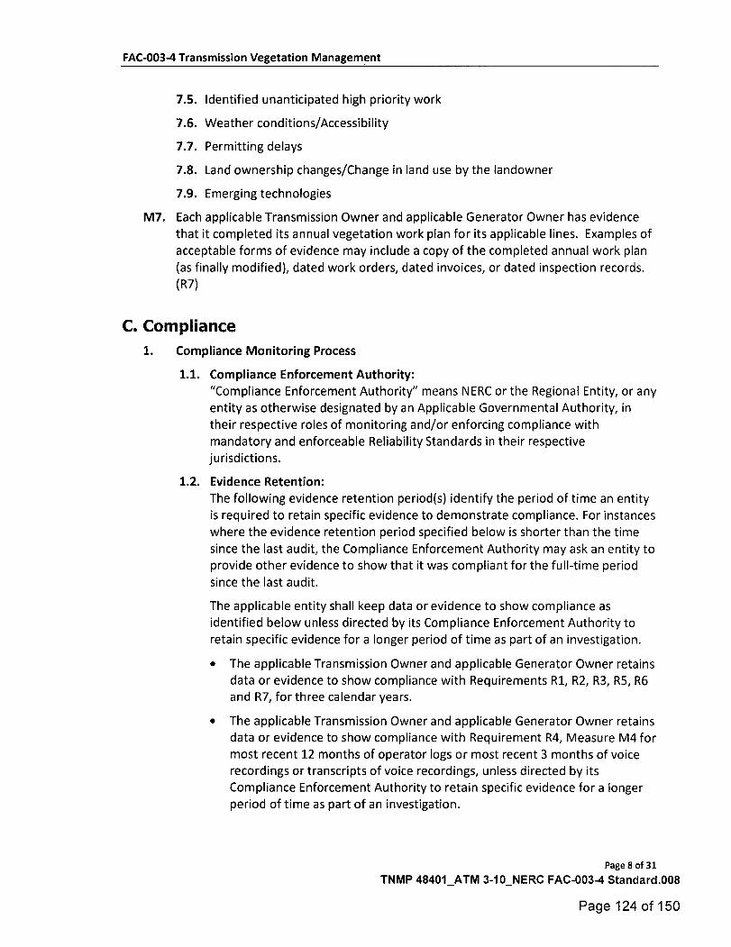
7.5. Identified unanticipated high priority work
7.6. Weather conditions/Accessibility
7.7. Permitting delays
7.8. Land ownership changes/Change in land use by the landowner
7.9. Emerging technologies
M7. Each applicable Transmission Owner and applicable Generator Owner has evidence
that it completed its annual vegetation work plan for its applicable lines. Examples of
acceptable forms of evidence may include a copy of the completed annual work plan
(as finally modified), dated work orders, dated invoices, or dated inspection records. (R7)
C. Compliance
1. Compliance Monitoring Process
1.1. Compliance Enforcement Authority:
"Compliance Enforcement Authority" means NERC or the Regional Entity, or any
entity as otherwise designated by an Applicable Governmental Authority, in
their respective roles of monitoring and/or enforcing compliance with mandatory and enforceable Reliability Standards in their respective
jurisdictions.
1.2. Evidence Retention:
The following evidence retention period(s) identify the period of time an entity
is required to retain specific evidence to demonstrate compliance. For instances where the evidence retention period specified below is shorter than the time
since the last audit, the Compliance Enforcement Authority may ask an entity to provide other evidence to show that it was compliant for the full-time period
since the last audit.
The applicable entity shall keep data or evidence to show compliance as
identified below unless directed by its Compliance Enforcement Authority to retain specific evidence for a longer period of time as part of an investigation.
• The applicable Transmission Owner and applicable Generator Owner retains
data or evidence to show compliance with Requirements R1, R2, R3, R5, R6 and R7, for three calendar years.
• The applicable Transmission Owner and applicable Generator Owner retains data or evidence to show compliance with Requirement R4, Measure M4 for most recent 12 months of operator logs or most recent 3 months of voice recordings or transcripts of voice recordings, unless directed by its Compliance Enforcement Authority to retain specific evidence for a longer period of time as part of an investigation.
Page 8 of 31
TNMP 48401_ATM 3-10_NERC FAC-003-4 Standard.008
Page 124 of 150
FAC-003-4 Transmission Vegetation Management
• If an applicable Transmission Owner or applicable Generator Owner is found
non-compliant, it shall keep information related to the non-compliance until
found compliant or for the time period specified above, whichever is longer.
1.3. Compliance Monitoring and Enforcement Program
As defined in the NERC Rules of Procedure, "Compliance Monitoring and
Enforcement Program" refers to the identification of the processes that will be
used to evaluate data or information for the purpose of assessing performance or outcomes with the associated Reliability Standard.
1.4. Additional Compliance Information
Periodic Data Submittal: The applicable Transmission Owner and applicable Generator Owner will submit a quarterly report to its Regional Entity, or the
Regional Entity's designee, identifying all Sustained Outages of applicable lines operated within their Rating and all Rated Electrical Operating Conditions as determined by the applicable Transmission Owner or applicable Generator
Owner to have been caused by vegetation, except as excluded in footnote 2,
and including as a minimum the following:
• The name of the circuit(s), the date, time and duration of the outage; the
voltage of the circuit; a description of the cause of the outage; the category
associated with the Sustained Outage; other pertinent comments; and any countermeasures taken by the applicable Transmission Owner or applicable Generator Owner.
A Sustained Outage is to be categorized as one of the following:
• Category 1A — Grow-ins: Sustained Outages caused by vegetation growing into applicable lines, that are identified as an element of an IROL or Major
WECC Transfer Path, by vegetation inside and/or outside of the ROW;
• Category 1B — Grow-ins: Sustained Outages caused by vegetation growing into applicable lines, but are not identified as an element of an IROL or
Major WECC Transfer Path, by vegetation inside and/or outside of the ROW;
• Category 2A — Fall-ins: Sustained Outages caused by vegetation falling into
applicable lines that are identified as an element of an IROL or Major WECC Transfer Path, from within the ROW;
• Category 2B — Fall-ins: Sustained Outages caused by vegetation falling into applicable lines, but are not identified as an element of an IROL or Major WECC Transfer Path, from within the ROW;
• Category 3 — Fall-ins: Sustained Outages caused by vegetation falling into
applicable lines from outside the ROW;
• Category 4A — Blowing together: Sustained Outages caused by vegetation and applicable lines that are identified as an element of an IROL or Major
WECC Transfer Path, blowing together from within the ROW;
Page 9 of 31
TNMP 48401_ATM 3-10_NERC FAC-003-4 Standard.009
Page 125 of 150
FAC-003-4 Transmission Vegetation Management
• Category 4B — Blowing together: Sustained Outages caused by vegetation
and applicable lines, but are not identified as an element of an IROL or Major WECC Transfer Path, blowing together from within the ROW.
The Regional Entity will report the outage information provided by applicable Transmission Owners and applicable Generator Owners, as per
the above, quarterly to NERC, as well as any actions taken by the Regional Entity as a result of any of the reported Sustained Outages.
Page 10 of 31
TNMP 48401_ATM 3-10_NERC FAC-003-4 Standard.010
Page 126 of 150
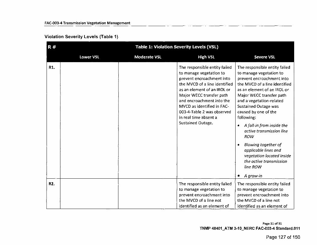
Table 1: Violation Severity Levels (VSL) R #
Lower VSL Moderate VSL High VSL Severe VSL
The responsible entity failed
to manage vegetation to
prevent encroachment into
the MVCD of a line identified
as an element of an IROL or
Major WECC transfer path
and encroachment into the
MVCD as identified in FAC-
003-4-Table 2 was observed
in real time absent a
Sustained Outage.
The responsible entity failed
to manage vegetation to
prevent encroachment into
the MVCD of a line identified
as an element of an IROL or
Major WECC transfer path
and a vegetation-related
Sustained Outage was
caused by one of the
following:
• A fall-in from inside the
active transmission line
ROW
• Blowing together of
applicable lines and
vegetation located inside
the active transmission
line ROW
• A grow-in
R1.
The responsible entity failed
to manage vegetation to
prevent encroachment into
the MVCD of a line not
identified as an element of
The responsible entity failed
to manage vegetation to
prevent encroachment into
the MVCD of a line not
identified as an element of
R2.
FAC-003-4 Transmission Vegetation Management
Violation Severity Levels (Table 1)
Page 11 of 31
TNMP 48401_ATM 3-10_NERC FAC-003-4 Standard.011
Page 127 of 150
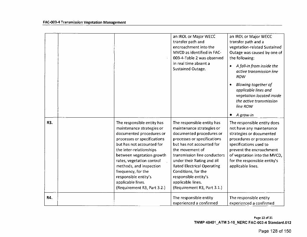
FAC-003-4 Transmission Vegetation Management
an IROL or Major WECC transfer path and
encroachment into the
MVCD as identified in FAC-
003-4-Table 2 was observed
in real time absent a
an IROL or Major WECC transfer path and a vegetation-related Sustained
Outage was caused by one of
the following:
• A fall-in from inside the Sustained Outage.
active transmission line ROW
• Blowing together of
applicable lines and
vegetation located inside
the active transmission line ROW
• A grow-in
R3. The responsible entity has The responsible entity has The responsible entity does
maintenance strategies or maintenance strategies or not have any maintenance documented procedures or documented procedures or strategies or documented
processes or specifications processes or specifications procedures or processes or but has not accounted for but has not accounted for specifications used to
the inter-relationships the movement of prevent the encroachment
between vegetation growth
rates, vegetation control •
transmission line conductors
under their Rating and all
of vegetation into the MVCD,
for the responsible entity's methods, and inspection
frequency, for the
responsible entity's
applicable lines.
Rated Electrical Operating
Conditions, for the
responsible entity's
applicable lines.
applicable lines.
(Requirement R3, Part 3.2.) (Requirement R3, Part 3.1.)
R4. The responsible entity experienced a confirmed
The responsible entity
experienced a confirmed
Page 12 of 31
TNMP 48401_ATM 3-10_NERC FAC-0034 Standard.012
Page 128 of 150
FAC-003-4 Transmission Vegetation Management
vegetation threat and
notified the control center
holding switching authority
for that applicable line, but
there was intentional delay
in that notification.
vegetation threat and did
not notify the control center
holding switching authority
for that applicable line.
R5. The responsible entity did
not take corrective action
when it was constrained
from performing planned
vegetation work where an
applicable line was put at
potential risk.
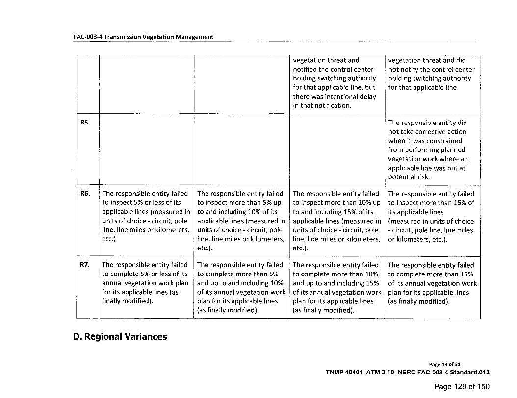
R6. The responsible entity failed
to inspect 5% or less of its
applicable lines (measured in
units of choice - circuit, pole
line, line miles or kilometers,
etc.)
The responsible entity failed
to inspect more than 5% up
to and including 10% of its
applicable lines (measured in
units of choice - circuit, pole
line, line miles or kilometers,
etc.).
The responsible entity failed
to inspect more than 10% up
to and including 15% of its
applicable lines (measured in
units of choice - circuit, pole
line, line miles or kilometers,
etc.).
The responsible entity failed
to inspect more than 15% of
its applicable lines
(measured in units of choice
- circuit, pole line, line miles
or kilometers, etc.).
R7. The responsible entity failed
to complete 5% or less of its
annual vegetation work plan
for its applicable lines (as
finally modified).
The responsible entity failed
to complete more than 5%
and up to and including 10%
of its annual vegetation work
plan for its applicable lines
(as finally modified).
The responsible entity failed
to complete more than 10%
and up to and including 15%
of its annual vegetation work
plan for its applicable lines
(as finally modified).
The responsible entity failed
to complete more than 15%
of its annual vegetation work
plan for its applicable lines
(as finally modified).
D. Regional Variances
Page 13 of 31
TNMP 48401_ATM 3-10_NERC FAC-003-4 Standard.013
Page 129 of 150
FAC-003-4 Transmission Vegetation Management
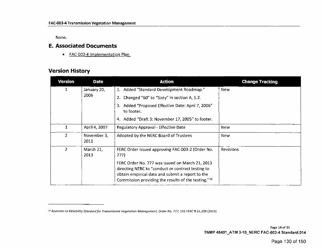
None.
E. Associated Documents
• FAC-003-4 Implementation Plan
Version History
Version Date Action Change Tracking
1 January 20,
2006
1. Added "Standard Development Roadmap."
2. Changed "60" to "Sixty" in section A, 5.2.
New
3. Added "Proposed Effective Date: April 7, 2006"
to footer.
4. Added "Draft 3: November 17, 2005" to footer.
1 April 4, 2007 Regulatory Approval - Effective Date New
2 November 3,
2011
Adopted by the NERC Board of Trustees New
2 March 21,
2013
FERC Order issued approving FAC-003-2 (Order No.
777)
Revisions
FERC Order No. 777 was issued on March 21, 2013
directing NERC to "conduct or contract testing to
obtain empirical data and submit a report to the
Commission providing the results of the testing."16
16 Revisions to Reliability Standard for Transmission Vegetation Management, Order No. 777, 142 FERC ¶ 61,208 (2013)
Page 14 of 31
TNMP 48401_ATM 3-10_NERC FAC-003-4 Standard.014
Page 130 of 150
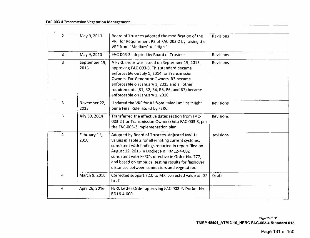
FAC-003-4 Transmission Vegetation Management
2 May 9, 2013 Board of Trustees adopted the modification of the
VRF for Requirement R2 of FAC-003-2 by raising the VRF from "Medium" to "High."
Revisions
3 May 9, 2013 FAC-003-3 adopted by Board of Trustees Revisions
3 September 19,
2013 A FERC order was issued on September 19, 2013,
approving FAC-003-3. This standard became
enforceable on July 1, 2014 for Transmission Owners. For Generator Owners, R3 became
enforceable on January 1, 2015 and all other
requirements (R1, R2, R4, R5, R6, and R7) became enforceable on January 1, 2016.
Revisions
3 November 22,
2013 Updated the VRF for R2 from "Medium" to "High" per a Final Rule issued by FERC
Revisions
3 July 30, 2014 Transferred the effective dates section from FAC-
003-2 (for Transmission Owners) into FAC-003-3, per
the FAC-003-3 implementation plan
Revisions
4 February 11,
2016 Adopted by Board of Trustees. Adjusted MVCD
values in Table 2 for alternating current systems,
consistent with findings reported in report filed on August 12, 2015 in Docket No. RM12-4-002
consistent with FERCs directive in Order No. 777,
and based on empirical testing results for flashover
distances between conductors and vegetation.
Revisions
4 March 9, 2016 Corrected subpart 7.10 to M7, corrected value of .07 to .7
Errata
4 April 26, 2016 FERC Letter Order approving FAC-003-4. Docket No. RD16-4-000.
Page 15 of 31
TNMP 48401_ATM 3-10_NERC FAC-003-4 Standard.015
Page 131 of 150
FAC-003-4 Transmission Vegetation Management
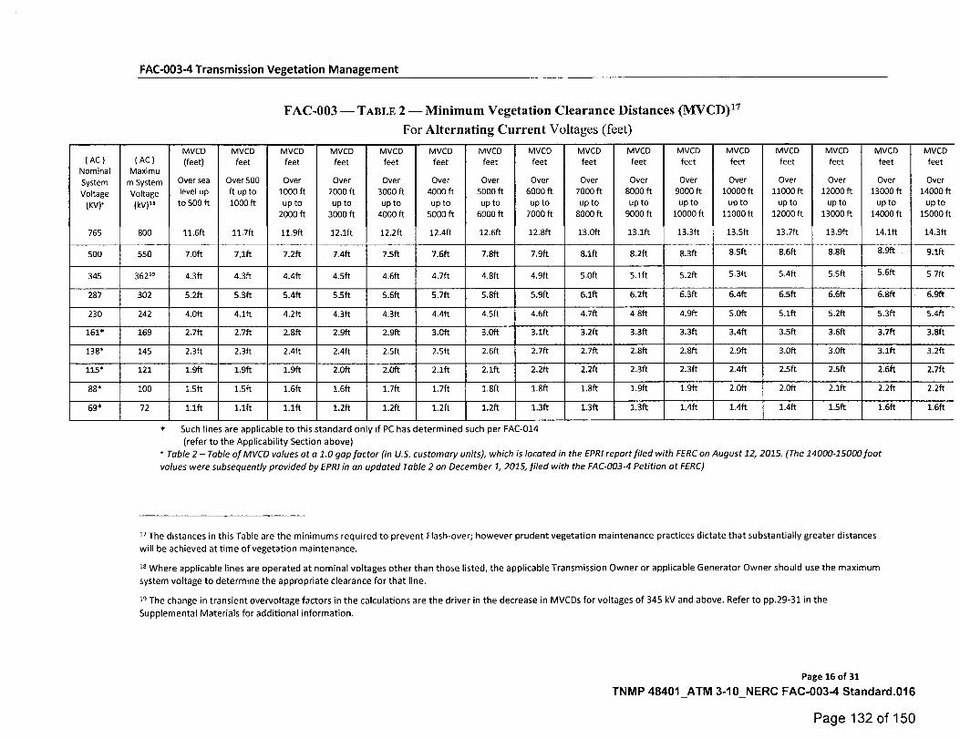
FAC-003 - TABLE 2 -Minimum Vegetation Clearance Distances (MVCD)17
For Alternating Current Voltages (feet)
( AC ) Nominal System Voltage
(KV).
765
( AC ) Maximu
m System Voltage (kV)"
800
MVCD (feet)
Over sea level up to 500 ft
11.6ft
MVCD feet
Over 500 ft up to 1000 ft
11.7ft
MVCD feet
Over 1000 ft up to
2000 ft
11.9ft
MVCD feet
Over 2000 ft up to
3000 ft
12.1ft
MVCD feet
Over 3000 ft up to
4000 ft
12.2ft
MVCD feet
Over 4000 ft up to
5000 ft
12.4ft
MVCD feet
Over 5000 ft up to
6000 ft
12.6ft
MVCD feet
Over 6000 ft up to
7000 ft
12.8ft
MVCD feet
Over 7000 ft up to
8000 ft
13.0ft
MVCD feet
Over 8000 ft up to
9000 ft
13.1ft
MVCD feet
Over 9000 ft up to
10000 ft
13.3ft
MVCD feet
Over 10000 ft
up to 11000 ft
13.5ft
MVCD feet
Over 11000 ft
up to 12000 ft
13.7ft
MVCD feet
Over 12000 ft
up to 13000 ft
13.9ft
MVCD feet
Over 13000 ft
up to 14000 ft
14.1ft
MVCD feet
Over 14000 ft
up to 15000 ft
14.3ft
500 550 7.0ft 7,1ft 7.2ft 7.4ft 7.5ft 7.6ft 7.8ft 7.9ft 8.1ft 8.2ft 8.3ft 8.5ft 8.6ft 8.8ft 8.9ft 9.1ft
345 362" 4.3ft 4.3ft 4.4ft 4.5ft 4.6ft 4.7ft 4.8ft 4.9ft 5.0ft 5.1ft 5.2ft 5.3ft 5.4ft 5.5ft 5.6ft 5.7ft
287 302 5.2ft 5.3ft 5.4ft 5.5ft 5.6ft 5.7ft 5.8ft 5.9ft 6.1ft 6.2ft 6.3ft 6.4ft 6.5ft 6.6ft 6.8ft 6.9ft
230 242 4.0ft 4.1ft 4.2ft 4.3ft 4.3ft 4.4ft 4.5ft 4.6ft 4.7ft 4 8ft 4.9ft 5.0ft 5.1ft 5.2ft 5.3ft 5.4ft
161* 169 2.7ft 2.7ft 2.8ft 2.9ft 2,9ft 3.0ft 3.0ft 3.1ft 3.2ft 3.3ft 3.3ft 3,4ft 3.5ft 3.6ft 3.7ft 3.8ft
138* 145 2.3ft 2.3ft 2.4ft 2.4ft 2.5ft 2.5ft 2.6ft 2.7ft 2.7ft 2.8ft 2.8ft 2.9ft 3.0ft 3.0ft 3.1ft 3.2ft
115* 121 1.9ft 1.9ft 1.9ft 2.0ft 2.0ft 2.1ft 2.1ft 2,2ft 2.2ft 2.3ft 2.3ft 2.4ft 25ft 2.5ft 2.6ft 2.7ft
88* 100 1.5ft 1.5ft 1.6ft 1.6ft 1.7ft 1.7ft 1.8ft 1.8ft 1.8ft 1.9ft 1.9ft 2.0ft 2.0ft 2.1ft 2.2ft 2.2ft
69* 72 1.1ft 1.1ft 1.1ft 1,2ft 1.2ft 1.2ft 1.2ft 1.3ft 1,3ft 1.3ft 1.4ft 1.4ft 1.4ft 1.5ft 1.6ft 1.6ft
Such lines are applicable to this standard on y if PC has determined such per FAC-014
(refer to the Applicability Section above)
Table 2 - Table of MVCD values at a 1.0 gap factor (in U.S. customary units), which is located in the EPRI report filed with FERC on August 12, 2015. (The 14000-15000 foot values were subsequently provided by EPRI in an updated Table 2 on December 1, 2015, filed with the FAC-003-4 Petition at FERC)
17 The distances in this Table are the minimums required to prevent Flash-over; however prudent vegetation maintenance practices dictate that substantially greater distances
will be achieved at time of vegetation maintenance.
18 Where applicable lines are operated at nominal voltages other than those listed, the applicable Transmission Owner or applicable Generator Owner should use the maximum
system voltage to determine the appropriate clearance for that line.
18 The change in transient overvoltage factors in the calculations are the driver in the decrease in MVCDs for voltages of 345 kV and above. Refer to pp.29-31 in the
Supplemental Materials for additional information.
Page 16 of 31
TNMP 48401_ATM 3-10_NERC FAC-003-4 Standard.016
Page 132 of 150
FAC-003-4 Transmission Vegetation Management
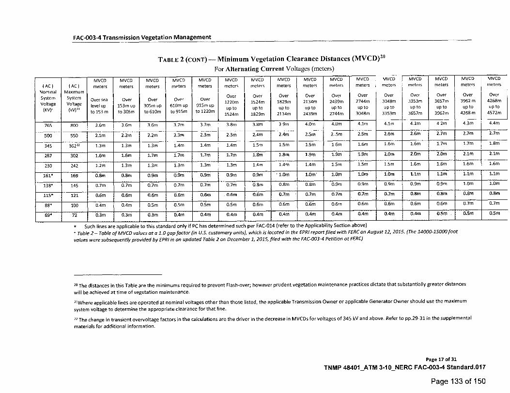
TABLE 2 (cow) - Minimum Vegetation Clearance Distances (MVCD)2°
For Alternating Current Voltages (meters)
( AC ) Nominal
System Voltage
(KV)*
( AC ) Maximum
System Voltage
("21
MVCD meters
Over sea level up
to 153 m
MVCD
meters
Over
153m up to 305m
MVCD meters
Over 305m up to 610m
MVCD meters
Over
610m up to 915m
MVCD meters
Over 915m up to 1220m
MVCD meters
Over
1220m
1up24m t o 5
MVCD
meters
Over
1524m up to
1829m
MVCD meters
Over 1829m up to
2134m
MVCD meters
Over 2134m up to
2439m
MVCD meters
Over 2439m up to
2744m
MVCD meters
Over 2744m
up to 3048m
MVCD
meters
Over
3048m up to
3353m
MVCD meters
Over 3353m up to
3657m
MVCD meters
Over
3657m up to
3962m
MVCD meters
Over
3962 m up to
4268 m
MVCD meters
Over 4268m up to
4572m
765 800 3.6m 3.6m 3.6m 3.7m 3.7m 3.8m 3.8m 3 9m 4.0m 4.0m 4.1m 4.1m 4.2m 4 2m 4.3m 4.4m
500 550 2.1m 2.2m 2.2m 2.3m 2.3m 2.3m 2.4m 2.4m 2.5m 2..5m 2.5m 2.6m 2.6m 2.7m 2.7m 2.7m
345 36222 1.3m 1.3m 1.3m 1.4m 1.4m 1.4m 1.5m 1.5m 1.5m 1.6m 1.6m 1.6m 1.6m 1.7m 1.7m 1.8m
287 302 1.6m 1.6m 1.7m 1.7m 1.7m 1.7m 1.8m 1.8m 1.9m 1.9m 1.9m 2.0m 2.0m 2.0m 2.1m 2.1m
230 242 1.2m 1.3m 1.3m 1.3m 1.3m 1.3m 1.4m 1.4m 1.4m 1.5m 1.5m 1.5m 1.6m 1.6m 1.6m 1.6m
161* 169 0.8m 0.8m 0.9m 0.9m 0.9m 0.9m 0.9m • 1.0m 1.0m 1.0m 1,0m 1.0m 1.1m 1.1m 1.1m 1,1m
138* 145 0.7m 0.7m 0.7m 0.7m 0.7m 0.7m 0.8m 0.8m 0.8m 0.9m 0.9m 0.9m 0.9m 0.9m 1.0m 1.0m
115* 121 0.6m 0.6m 0.6m 0.6m 0.6m 0.6m 0.6m 0.7m 0.7m 0.7m 0.7m 0.7m 0.8m 0.8m 0.8m 0.8m
88* 100 0.4m 0.4m 0.5m 0.5m 0.5m 0.5m 0.6m 0.6m 0.6m 0.6m 0.6m 0.6m 0.6m 0.6m 0.7m 0.7m
69* 72 0.3m 0.3m 0.3m 0.4m 0.4m 0.4m 0.4m 0.4m 0.4m 0.4m 0.4m 0.4m 0.4m 0.5M 0.5m 0.5m
* Such lines are applicable to this standard only if PC has determined such per FAC-014 (refer to the Applicability Section above)
* Table 2 - Table of MVCD values at a 1.0 gap factor (in U.S. customary units), which is located in the EPRI report filed with FERC on August 12, 2015. (The 14000-15000 foot
values were subsequently provided by EPRI in an updated Table 2 on December I, 2015, filed with the FAC-003-4 Petition at FERC)
20 The distances in this Table are the minimums required to prevent Flash-over; however prudent vegetation maintenance practices dictate that substantially greater distances
will be achieved at time of vegetation maintenance.
21M/here applicable lines are operated at nominal voltages other than those listed, the applicable Transmission Owner or applicable Generator Owner should use the maximum
system voltage to determine the appropriate clearance for that line.
22 The change in transient overvoltage factors in the calculations are the driver in the decrease in MVCDs for voltages of 345 kV and above. Refer to pp.29-31 in the supplemental
materials for additional information.
Page 17 of 31
TNMP 48401_ATM 3-10_NERC FAC-003-4 Standard.017
Page 133 of 150
FAC-003-4 Transmission Vegetation Management
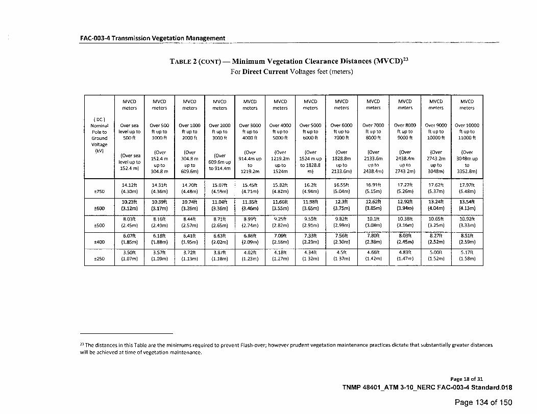
TABLE 2 (cow) - Minimum Vegetation Clearance Distances (MVCD)23 For Direct Current Voltages feet (meters)
( DC ) Nominal
Pole to Ground Voltage
(kV)
MVCD
meters
Over sea level up to
500 ft
level up to 152.4 m)
( Ov er sea
MVCD
meters
Over 500 ft up to 1000 ft
(Over 152.4 m
up to
MVCD
meters
Over 1000 ft up to 2000 ft
(Over 304.8 m
up to
MVCD meters
Over 2000 ft upto 3000 ft
(Over
609.6m up to 914.4m
MVCD meters
Over 3000 ft up to 4000 ft
(Over 914.4m up
to
MVCD meters
Over 4000 ft up to 5000 ft
(Over
1219.2m
up to
MVCD meters
Over 5000 ft up to 6000 ft
(Over 1524 m up
to 1828.8
MVCD
meters
Over 6000 ft up to 7000 ft
(Over 1828.8m
up to
MVCD meters
Over 7000 ft up to 8000 ft
(Over 2133.6m
up to
MVCD meters
Over 8000 ft up to 9000 ft
(Over 2438.4m
up to
MVCD
meters
Over 9000 ft up to 10000 ft
(Over 2743.2m
up to
MVCD meters
Over 10000 ft upto 11000 ft
(Over 3048m up
to 304.8 m 609.6m) 1219.2m 1524m m) 2133.6m) 2438.4m) 2743 2m) 3048m) 3352.8m)
14.12ft 14.31ft 14.70ft 15.07ft 15.45ft 15.82ft 16.2ft 16.55ft 16.91ft 17.27ft 17.62ft 17.97ft
±750 (4.30m) (4.36m) (4.48m) (4.59m) (4.71m) (4.82m) (4.94m) (5.04m) (5.15m) (5.26m) (5.37m) (5.48m)
10.23ft 10.39ft 10.74ft 11.04ft 11.35ft 11.66ft 11.98ft 12.3ft 12.62ft 12.92ft 13.24ft 13.54ft
±600 (3.12m) (3.17m) (3.26m) (3.36m) (3.46m) (3.55m) (3.65m) (3.75m) (3.85m) (3.94m) (4.04m) (4.13m)
8.03ft 8.16ft 8.44ft 8.71ft 8.99ft 9.25ft 9.55ft 9.82ft 10.1ft 10.38ft 10.65ft 10.92ft ±500 (2.45m) (2.49m) (2.57m) (2.65m) (2.74m) (2.82m) (2.91m) (2.99m) (3.08m) (3.16m) (3.25m) (3.33m)
6.07ft 6.18ft 6.41ft 6.63ft 6.86ft 7.09ft 7.33ft 7.56ft 7.80ft 8.03ft 8.27ft 8.51ft ±400 (1.85m) (1.88m) (1.95m) (2.02m) (2.09m) (2.16m) (2.23m) (2.30m) (2.38m) (2.45m) (2.52m) (2.59m)
3.50ft 3.57ft 3.72ft 3.87ft 4.02ft 4.18ft 4.34ft 4.5ft 4.66ft 4.83ft 5.00ft 5.17ft ±250 (1.07m) (1.09m) (1.13m) (1.18m) (1.23m) (1.27m) (1 32m) (1 37m) (1.42m) (1.47m) (1.52m) (1.58m)
23 The distances in this Table are the minimums required to prevent Flash-over; however prudent vegetation maintenance practices dictate that substantially greater distances
will be achieved at time of vegetation maintenance.
Page 18 of 31
TNMP 48401_ATM 3-10_NERC FAC-003-4 Standard.018
Page 134 of 150
Supplemental Material
Guideline and Technical Basis
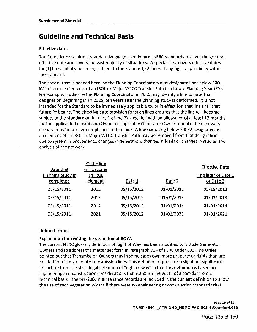
Effective dates:
The Compliance section is standard language used in most NERC standards to cover the general effective date and covers the vast majority of situations. A special case covers effective dates
for (1) lines initially becoming subject to the Standard, (2) lines changing in applicability within
the standard.
The special case is needed because the Planning Coordinators may designate lines below 200 kV to become elements of an IROL or Major WECC Transfer Path in a future Planning Year (PY).
For example, studies by the Planning Coordinator in 2015 may identify a line to have that designation beginning in PY 2025, ten years after the planning study is performed. It is not
intended for the Standard to be immediately applicable to, or in effect for, that line until that
future PY begins. The effective date provision for such lines ensures that the line will become
subject to the standard on January 1 of the PY specified with an allowance of at least 12 months for the applicable Transmission Owner or applicable Generator Owner to make the necessary preparations to achieve compliance on that line. A line operating below 200kV designated as an element of an IROL or Major WECC Transfer Path may be removed from that designation
due to system improvements, changes in generation, changes in loads or changes in studies and analysis of the network.
Date that
Planning Study is completed
PY the line will become
an IROL
element
Effective Date
The later of Date 1 or Date 2 Date 1
Date 2
05/15/2011 2012 05/15/2012 01/01/2012 05/15/2012
05/15/2011 2013 05/15/2012 01/01/2013 01/01/2013
05/15/2011 2014 05/15/2012 01/01/2014 01/01/2014
05/15/2011 2021 05/15/2012 01/01/2021 01/01/2021
Defined Terms:
Explanation for revising the definition of ROW:
The current NERC glossary definition of Right of Way has been modified to include Generator
Owners and to address the matter set forth in Paragraph 734 of FERC Order 693. The Order pointed out that Transmission Owners may in some cases own more property or rights than are needed to reliably operate transmission lines. This definition represents a slight but significant departure from the strict legal definition of "right of way" in that this definition is based on
engineering and construction considerations that establish the width of a corridor from a technical basis. The pre-2007 maintenance records are included in the current definition to allow the use of such vegetation widths if there were no engineering or construction standards that
Page 19 of 31
TNMP 48401_ATM 3-10_NERC FAC-003-4 Standard.019
Page 135 of 150
Supplemental Material
referenced the width of right of way to be maintained for vegetation on a particular line but the
evidence exists in maintenance records for a width that was in fact maintained prior to this standard becoming mandatory. Such widths may be the only information available for lines that had limited or no vegetation easement rights and were typically maintained primarily to ensure
public safety. This standard does not require additional easement rights to be purchased to satisfy a minimum right of way width that did not exist prior to this standard becoming
mandatory.
Explanation for revising the definition of Vegetation Inspection:
The current glossary definition of this NERC term was modified to include Generator Owners and to allow both maintenance inspections and vegetation inspections to be performed concurrently. This allows potential efficiencies, especially for those lines with minimal vegetation and/or slow vegetation growth rates.
Explanation of the derivation of the MVCD:
The MVCD is a calculated minimum distance that is derived from the Gallet equation. This is a method of calculating a flash over distance that has been used in the design of high voltage
transmission lines. Keeping vegetation away from high voltage conductors by this distance will prevent voltage flash-over to the vegetation. See the explanatory text below for Requirement R3
and associated Figure 1. Table 2 of the Standard provides MVCD values for various voltages and altitudes. The table is based on empirical testing data from EPRI as requested by FERC in Order No. 777.
Project 2010-07.1 Adjusted MVCDs per EPRI Testing:
In Order No. 777, FERC directed NERC to undertake testing to gather empirical data validating the appropriate gap factor used in the Gallet equation to calculate MVCDs, specifically the gap
factor for the flash-over distances between conductors arid vegetation. See, Order No. 777, at P
60. NERC engaged industry through a collaborative research project and contracted EPRI to complete the scope of work. In January 2014, NERC formed an advisory group to assist with
developing the scope of work for the project. This team provided subject matter expertise for developing the test plan, monitoring testing, and vetting the analysis and conclusions to be
submitted in a final report. The advisory team was comprised of NERC staff, arborists, and industry members with wide-ranging expertise in transmission engineering, insulation
coordination, and vegetation management. The testing project commenced in April 2014 and
continued through October 2014 with the final set of testing completed in May 2015. Based on
these testing results conducted by EPRI, and consistent with the report filed in FERC Docket No. RM12-4-000, the gap factor used in the Gallet equation required adjustment from 1.3 to 1.0.
This resulted in increased MVCD values for all alternating current system voltages identified. The adjusted MVCD values, reflecting the 1.0 gap factor, are included in Table 2 of version 4 of FAC-003.
The air gap testing completed by EPRI per FERC Order No. 777 established that trees with large spreading canopies growing directly below energized high voltage conductors create the
Page 20 of 31
TNMP 48401_ATM 3-10_NERC FAC-003-4 Standard.020
Page 136 of 150
Supplemental Material
greatest likelihood of an air gap flash over incident and was a key driver in changing the gap factor to a more conservative value of 1.0 in version 4 of this standard.
Requirements R1 and R2:
R1 and R2 are performance-based requirements. The reliability objective or outcome to be
achieved is the management of vegetation such that there are no vegetation encroachments
within a minimum distance of transmission lines. Content-wise, R1 and R2 are the same
requirements; however, they apply to different Facilities. Both R1 and R2 require each applicable
Transmission Owner or applicable Generator Owner to manage vegetation to prevent encroachment within the MVCD of transmission lines. R1 is applicable to lines that are identified as an element of an IROL or Major WECC Transfer Path. R2 is applicable to all other lines that are
not elements of IROLs, and not elements of Major WECC Transfer Paths.
The separation of applicability (between R1 and R2) recognizes that inadequate vegetation
management for an applicable line that is an element of an IROL or a Major WECC Transfer Path
is a greater risk to the interconnected electric transmission system than applicable lines that are
not elements of IROLs or Major WECC Transfer Paths. Applicable lines that are not elements of
IROLs or Major WECC Transfer Paths do require effective vegetation management, but these lines are comparatively less operationally significant.
Requirements R1 and R2 state that if inadequate vegetation management allows vegetation to encroach within the MVCD distance as shown in Table 2, it is a violation of the standard. Table 2
distances are the minimum clearances that will prevent spark-over based on the Gallet equations. These requirements assume that transmission lines and their conductors are operating within their Rating. If a line conductor is intentionally or inadvertently operated beyond its Rating and
Rated Electrical Operating Condition (potentially in violation of other standards), the occurrence
of a clearance encroachment may occur solely due to that condition. For example, emergency actions taken by an applicable Transmission Owner or applicable Generator Owner or Reliability
Coordinator to protect an Interconnection may cause excessive sagging and an outage. Another example would be ice loading beyond the line's Rating and Rated Electrical Operating Condition.
Such vegetation-related encroachments and outages are not violations of this standard.
Evidence of failures to adequately manage vegetation include real-time observation of a
vegetation encroachment into the MVCD (absent a Sustained Outage), or a vegetation-related encroachment resulting in a Sustained Outage due to a fall-in from inside the ROW, or a
vegetation-related encroachment resulting in a Sustained Outage due to the blowing together of the lines and vegetation located inside the ROW, or a vegetation-related encroachment resulting
in a Sustained Outage due to a grow-in. Faults which do not cause a Sustained outage and which are confirmed to have been caused by vegetation encroachment within the MVCD are considered the equivalent of a Real-time observation for violation severity levels.
With this approach, the VSLs for R1 and R2 are structured such that they directly correlate to the severity of a failure of an applicable Transmission Owner or applicable Generator Owner to
manage vegetation and to the corresponding performance level of the Transmission Owner's
Page 21 of 31
TNMP 48401_ATM 3-10_NERC FAC-003-4 Standard.021
Page 137 of 150
Supplemental Material
vegetation program's ability to meet the objective of "preventing the risk of those vegetation
related outages that could lead to Cascading." Thus violation severity increases with an applicable Transmission Owner's or applicable Generator Owner's inability to meet this goal and its potential of leading to a Cascading event. The additional benefits of such a combination are
that it simplifies the standard and clearly defines performance for compliance. A performance-
based requirement of this nature will promote high quality, cost effective vegetation management programs that will deliver the overall end result of improved reliability to the
system.
Multiple Sustained Outages on an individual line can be caused by the same vegetation. For example initial investigations and corrective actions may not identify and remove the actual
outage cause then another outage occurs after the line is re-energized and previous high conductor temperatures return. Such events are considered to be a single vegetation-related
Sustained Outage under the standard where the Sustained Outages occur within a 24 hour period.
lf the applicable Transmission Owner or applicable Generator Owner has applicable lines
operated at nominal voltage levels not listed in Table 2, then the applicable TO or applicable GO
should use the next largest clearance distance based on the next highest nominal voltage in the table to determine an acceptable distance.
Requirement R3:
R3 is a competency based requirement concerned with the maintenance strategies,
procedures, processes, or specifications, an applicable Transmission Owner or applicable Generator Owner uses for vegetation management.
An adequate transmission vegetation management program formally establishes the approach
the applicable Transmission Owner or applicable Generator Owner uses to plan and perform vegetation work to prevent transmission Sustained Outages and minimize risk to the
transmission system. The approach provides the basis for evaluating the intent, allocation of
appropriate resources, and the competency of the applicable Transmission Owner or applicable Generator Owner in managing vegetation. There are many acceptable approaches to manage vegetation and avoid Sustained Outages. However, the applicable Transmission Owner or applicable Generator Owner must be able to show the documentation of its approach and how it conducts work to maintain clearances.
An example of one approach commonly used by industry is ANSI Standard A300, part 7.
However, regardless of the approach a utility uses to manage vegetation, any approach an applicable Transmission Owner or applicable Generator Owner chooses to use will generally contain the following elements:
1. the maintenance strategy used (such as minimum vegetation-to-conductor distance
or maximum vegetation height) to ensure that MVCD clearances are never violated
Page 22 of 31
TNMP 48401_ATM 3-10_NERC FAC-003-4 Standard.022
Page 138 of 150
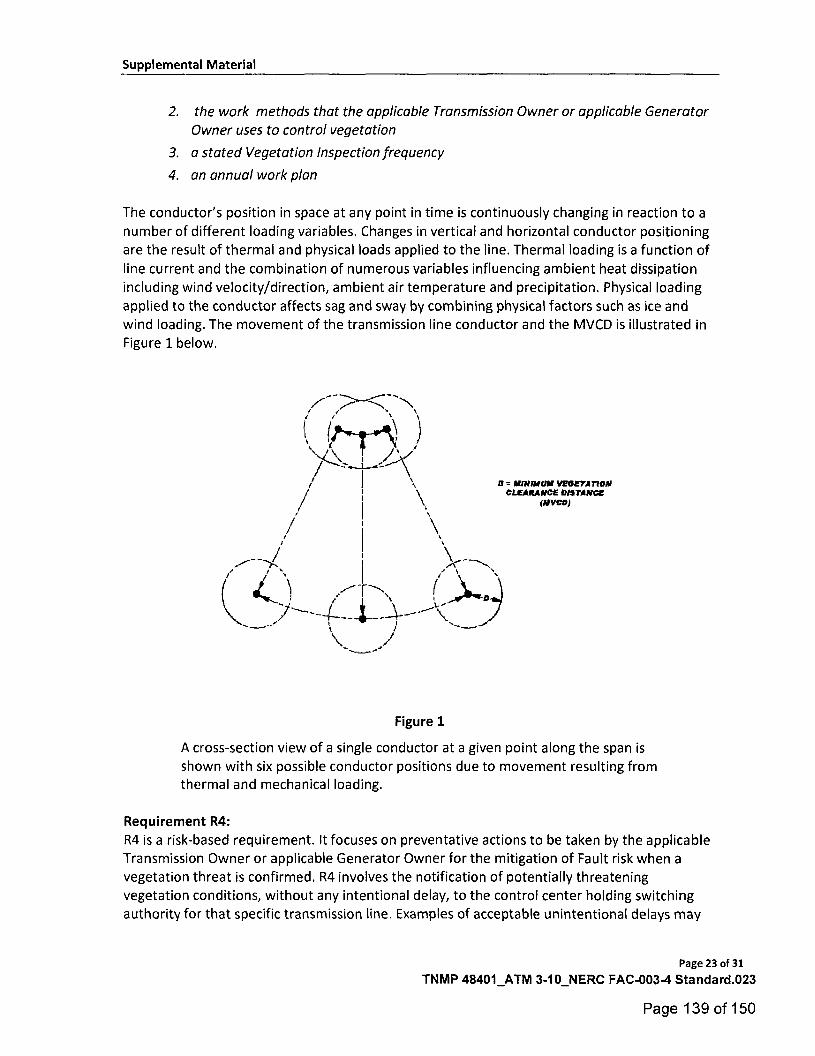
z------'-'-c-'\,
Supplemental Material
2. the work methods that the applicable Transmission Owner or applicable Generator
Owner uses to control vegetation
3. a stated Vegetation Inspection frequency
4. an annual work plan
The conductor's position in space at any point in time is continuously changing in reaction to a
number of different loading variables. Changes in vertical and horizontal conductor positioning are the result of thermal and physical loads applied to the line. Thermal loading is a function of
line current and the combination of numerous variables influencing ambient heat dissipation
including wind velocity/direction, ambient air temperature and precipitation. Physical loading
applied to the conductor affects sag and sway by combining physical factors such as ice and wind loading. The movement of the transmission line conductor and the MVCD is illustrated in
Figure 1 below.
D =-• IIINHAVII VEGETATION CLEARANCE INSTANCE
(NYCO
Figure 1
A cross-section view of a single conductor at a given point along the span is
shown with six possible conductor positions due to movement resulting from thermal and mechanical loading.
Requirement R4:
R4 is a risk-based requirement. It focuses on preventative actions to be taken by the applicable
Transmission Owner or applicable Generator Owner for the mitigation of Fault risk when a vegetation threat is confirmed. R4 involves the notification of potentially threatening
vegetation conditions, without any intentional delay, to the control center holding switching authority for that specific transmission line. Examples of acceptable unintentional delays may
Page 23 of 31
TNMP 48401_ATM 3-10_NERC FAC-003-4 Standard.023
Page 139 of 150

Supplemental Material
include communication system problems (for example, cellular service or two-way radio disabled), crews located in remote field locations with no communication access, delays due to severe weather, etc.
Confirmation is key that a threat actually exists due to vegetation. This confirmation could be in
the form of an applicable Transmission Owner or applicable Generator Owner employee who personally identifies such a threat in the field. Confirmation could also be made by sending out an employee to evaluate a situation reported by a landowner.
Vegetation-related conditions that warrant a response include vegetation that is near or
encroaching into the MVCD (a grow-in issue) or vegetation that could fall into the transmission
conductor (a fall-in issue). A knowledgeable verification of the risk would include an assessment of the possible sag or movement of the conductor while operating between no-load conditions and its rating.
The applicable Transmission Owner or applicable Generator Owner has the responsibility to ensure the proper communication between field personnel and the control center to allow the control center to take the appropriate action until or as the vegetation threat is relieved. Appropriate actions may include a temporary reduction in the line loading, switching the line out of service, or other preparatory actions in recognition of the increased risk of outage on that circuit. The notification of the threat should be communicated in terms of minutes or hours as opposed to a longer time frame for corrective action plans (see R5).
All potential grow-in or fall-in vegetation-related conditions will not necessarily cause a Fault at any moment. For example, some applicable Transmission Owners or applicable Generator
Owners may have a danger tree identification program that identifies trees for removal with the potential to fall near the line. These trees would not require notification to the control center unless they pose an immediate fall-in threat.
Requirement R5:
R5 is a risk-based requirement. It focuses upon preventative actions to be taken by the
applicable Transmission Owner or applicable Generator Owner for the mitigation of Sustained Outage risk when temporarily constrained from performing vegetation maintenance. The intent
of this requirement is to deal with situations that prevent the applicable Transmission Owner or
applicable Generator Owner from performing planned vegetation management work and, as a result, have the potential to put the transmission line at risk. Constraints to performing vegetation maintenance work as planned could result from legal injunctions filed by property
owners, the discovery of easement stipulations which limit the applicable Transmission Owner's or applicable Generator Owner's rights, or other circumstances.
This requirement is not intended to address situations where the transmission line is not at potential risk and the work event can be rescheduled or re-planned using an alternate work methodology. For example, a land owner may prevent the planned use of herbicides to control incompatible vegetation outside of the MVCD, but agree to the use of mechanical clearing. In
Page 24 of 31
TNMP 48401_ATM 3-10_NERC FAC-003-4 Standard.024
Page 140 of 150
Supplemental Material
this case the applicable Transmission Owner or applicable Generator Owner is not under any
immediate time constraint for achieving the management objective, can easily reschedule work using an alternate approach, and therefore does not need to take interim corrective action.
However, in situations where transmission line reliability is potentially at risk due to a
constraint, the applicable Transmission Owner or applicable Generator Owner is required to
take an interim corrective action to mitigate the potential risk to the transmission line. A wide
range of actions can be taken to address various situations. General considerations include:
• Identifying locations where the applicable Transmission Owner or applicable Generator
Owner is constrained from performing planned vegetation maintenance work which
potentially leaves the transmission line at risk.
• Developing the specific action to mitigate any potential risk associated with not performing the vegetation maintenance work as planned.
• Documenting and tracking the specific action taken for the location.
• In developing the specific action to mitigate the potential risk to the transmission line the applicable Transmission Owner or applicable Generator Owner could consider
location specific measures such as modifying the inspection and/or maintenance
intervals. Where a legal constraint would not allow any vegetation work, the interim corrective action could include limiting the loading on the transmission line.
• The applicable Transmission Owner or applicable Generator Owner should document and track the specific corrective action taken at each location. This location may be
indicated as one span, one tree or a combination of spans on one property where the constraint is considered to be temporary.
Requirement R6:
R6 is a risk-based requirement. This requirement sets a minimum time period for completing Vegetation Inspections. The provision that Vegetation Inspections can be performed in
conjunction with general line inspections facilitates a Transmission Owner's ability to meet this requirement. However, the applicable Transmission Owner or applicable Generator Owner
may determine that more frequent vegetation specific inspections are needed to maintain
reliability levels, based on factors such as anticipated growth rates of the local vegetation, length of the local growing season, limited ROW width, and local rainfall. Therefore it is
expected that some transmission lines may be designated with a higher frequency of
inspections.
The VSLs for Requirement R6 have levels ranked by the failure to inspect a percentage of the applicable lines to be inspected. To calculate the appropriate VSL the applicable Transmission
Owner or applicable Generator Owner may choose units such as: circuit, pole line, line miles or kilometers, etc.
For example, when an applicable Transmission Owner or applicable Generator Owner operates 2,000 miles of applicable transmission lines this applicable Transmission Owner or applicable
Page 25 of 31
TNMP 48401_ATM 3-10_NERC FAC-003-4 Standard.025
Page 141 of 150
Supplemental Material
Generator Owner will be responsible for inspecting all the 2,000 miles of lines at least once
during the calendar year. If one of the included lines was 100 miles long, and if it was not
inspected during the year, then the amount failed to inspect would be 100/2000 = 0.05 or 5%. The "Low VSL" for R6 would apply in this example.
Requirement R7:
R7 is a risk-based requirement. The applicable Transmission Owner or applicable Generator Owner is required to complete its annual work plan for vegetation management to accomplish
the purpose of this standard. Modifications to the work plan in response to changing conditions or to findings from vegetation inspections may be made and documented provided they do not
put the transmission system at risk. The annual work plan requirement is not intended to
necessarily require a "span-by-span", or even a "line-by-line detailed description of all work to be performed. It is only intended to require that the applicable Transmission Owner or applicable Generator Owner provide evidence of annual planning and execution of a vegetation
management maintenance approach which successfully prevents encroachment of vegetation into the MVCD.
When an applicable Transmission Owner or applicable Generator Owner identifies 1,000 miles of applicable transmission lines to be completed in the applicable Transmission Owner's or
applicable Generator Owner's annual plan, the applicable Transmission Owner or applicable Generator Owner will be responsible completing those identified miles. If an applicable
Transmission Owner or applicable Generator Owner makes a modification to the annual plan
that does not put the transmission system at risk of an encroachment the annual plan may be modified. If 100 miles of the annual plan is deferred until next year the calculation to
determine what percentage was completed for the current year would be: 1000 — 100
(deferred miles) = 900 modified annual plan, or 900 / 900 = 100% completed annual miles. If an applicable Transmission Owner or applicable Generator Owner only completed 875 of the total
1000 miles with no acceptable documentation for modification of the annual plan the calculation for failure to complete the annual plan would be: 1000 — 875 = 125 miles failed to complete then, 125 miles (not completed) / 1000 total annual plan miles = 12.5% failed to
complete.
The ability to modify the work plan allows the applicable Transmission Owner or applicable
Generator Owner to change priorities or treatment methodologies during the year as conditions or situations dictate. For example recent line inspections may identify unanticipated
high priority work, weather conditions (drought) could make herbicide application ineffective during the plan year, or a major storm could require redirecting local resources away from
planned maintenance. This situation may also include complying with mutual assistance agreements by moving resources off the applicable Transmission Owner's or applicable
Generator Owner's system to work on another system. Any of these examples could result in
acceptable deferrals or additions to the annual work plan provided that they do not put the transmission system at risk of a vegetation encroachment.
In general, the vegetation management maintenance approach should use the full extent of the
applicable Transmission Owner's or applicable Generator Owner's easement, fee simple and
Page 26 of 31
TNMP 48401_ATM 3-10_NERC FAC-003-4 Standard.026
Page 142 of 150
Supplemental Material
other legal rights allowed. A comprehensive approach that exercises the full extent of legal rights on the ROW is superior to incremental management because in the long term it reduces
the overall potential for encroachments, and it ensures that future planned work and future
planned inspection cycles are sufficient.
When developing the annual work plan the applicable Transmission Owner or applicable
Generator Owner should allow time for procedural requirements to obtain permits to work on
federal, state, provincial, public, tribal lands. In some cases the lead time for obtaining permits
may necessitate preparing work plans more than a year prior to work start dates. Applicable
Transmission Owners or applicable Generator Owners may also need to consider those special
landowner requirements as documented in easement instruments.
This requirement sets the expectation that the work identified in the annual work plan will be
completed as planned. Therefore, deferrals or relevant changes to the annual plan shall be documented. Depending on the planning and documentation format used by the applicable
Transmission Owner or applicable Generator Owner, evidence of successful annual work plan execution could consist of signed-off work orders, signed contracts, printouts from work management systems, spreadsheets of planned versus completed work, timesheets, work
inspection reports, or paid invoices. Other evidence may include photographs, and walk-through reports.
Notes:
The SDT determined that the use of IEEE 516-2003 in version 1 of FAC-003 was a misapplication. The SDT consulted specialists who advised that the Gallet equation would be a technically
justified method. The explanation of why the Gallet approach is more appropriate is explained in the paragraphs below.
The drafting team sought a method of establishing minimum clearance distances that uses realistic weather conditions and realistic maximum transient over-voltages factors for in-service transmission lines.
The SDT considered several factors when looking at changes to the minimum vegetation to conductor distances in FAC-003-1:
• avoid the problem associated with referring to tables in another standard (IEEE-516-2003)
• transmission lines operate in non-laboratory environments (wet conditions)
• transient over-voltage factors are lower for in-service transmission lines than for inadvertently re-energized transmission lines with trapped charges.
FAC-003-1 used the minimum air insulation distance (MAID) without tools formula provided in
IEEE 516-2003 to determine the minimum distance between a transmission line conductor and vegetation. The equations and methods provided in IEEE 516 were developed by an IEEE Task Force in 1968 from test data provided by thirteen independent laboratories. The distances
provided in IEEE 516 Tables 5 and 7 are based on the withstand voltage of a dry rod-rod air gap,
Page 27 of 31
TNMP 48401_ATM 3-10_NERC FAC-003-4 Standard.027
Page 143 of 150

Supplemental Material
or in other words, dry laboratory conditions. Consequently, the validity of using these distances in an outside environment application has been questioned.
FAC-003-1 allowed Transmission Owners to use either Table 5 or Table 7 to establish the
minimum clearance distances. Table 7 could be used if the Transmission Owner knew the
maximum transient over-voltage factor for its system. Otherwise, Table 5 would have to be used. Table 5 represented minimum air insulation distances under the worst possible case for transient over-voltage factors. These worst case transient over-voltage factors were as follows:
3.5 for voltages up to 362 kV phase to phase; 3.0 for 500 - 550 kV phase to phase; and 2.5 for 765 to 800 kV phase to phase. These worst case over-voltage factors were also a cause for concern in this particular application of the distances.
In general, the worst case transient over-voltages occur on a transmission line that is
inadvertently re-energized immediately after the line is de-energized and a trapped charge is
still present. The intent of FAC-003 is to keep a transmission line that is in service from
becoming de-energized (i.e. tripped out) due to spark-over from the line conductor to nearby vegetation. Thus, the worst case transient overvoltage assumptions are not appropriate for this application. Rather, the appropriate over voltage values are those that occur only while the line is energized.
Typical values of transient over-voltages of in-service lines are not readily available in the literature because they are negligible compared with the maximums. A conservative value for
the maximum transient over-voltage that can occur anywhere along the length of an in-service ac line was approximately 2.0 per unit. This value was a conservative estimate of the transient over-voltage that is created at the point of application (e.g. a substation) by switching a
capacitor bank without pre-insertion devices (e.g. closing resistors). At voltage levels where capacitor banks are not very common (e.g. Maximum System Voltage of 362 kV), the maximum
transient over-voltage of an in-service ac line are created by fault initiation on adjacent ac lines
and shunt reactor bank switching. These transient voltages are usually 1.5 per unit or less.
Even though these transient over-voltages will not be experienced at locations remote from the
bus at which they are created, in order to be conservative, it is assumed that all nearby ac lines are subjected to this same level of over-voltage. Thus, a maximum transient over-voltage factor
of 2.0 per unit for transmission lines operated at 302 kV and below was considered to be a realistic maximum in this application. Likewise, for ac transmission lines operated at Maximum
System Voltages of 362 kV and above a transient over-voltage factor of 1.4 per unit was considered a realistic maximum.
The Gallet equations are an accepted method for insulation coordination in tower design. These equations are used for computing the required strike distances for proper transmission line insulation coordination. They were developed for both wet and dry applications and can be
used with any value of transient over-voltage factor. The Gallet equation also can take into account various air gap geometries. This approach was used to design the first 500 kV and 765 kV lines in North America.
Page 28 of 31
TNMP 48401_ATM 3-10_NERC FAC-003-4 Standard.028
Page 144 of 150
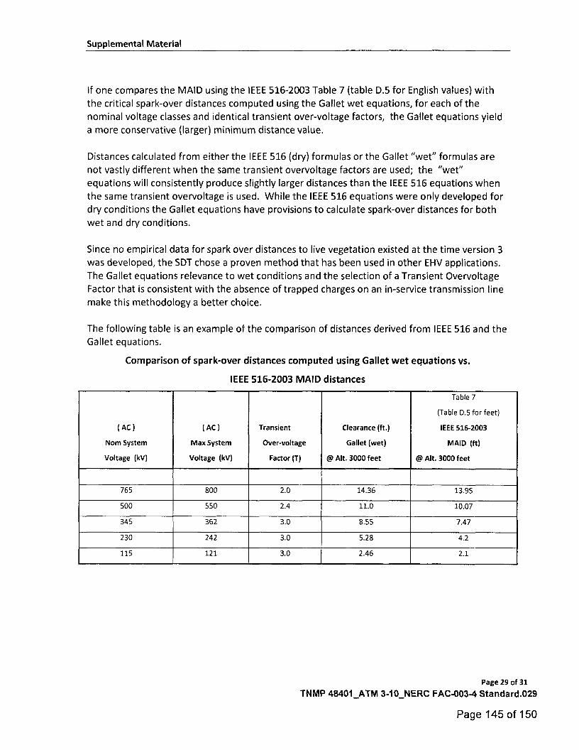
Supplemental Material
If one compares the MAID using the IEEE 516-2003 Table 7 (table D.5 for English values) with the critical spark-over distances computed using the Gallet wet equations, for each of the nominal voltage classes and identical transient over-voltage factors, the Gallet equations yield a more conservative (larger) minimum distance value.
Distances calculated from either the IEEE 516 (dry) formulas or the Gallet "wet" formulas are not vastly different when the same transient overvoltage factors are used; the "wet" equations will consistently produce slightly larger distances than the IEEE 516 equations when the same transient overvoltage is used. While the IEEE 516 equations were only developed for dry conditions the Gallet equations have provisions to calculate spark-over distances for both wet and dry conditions.
Since no empirical data for spark over distances to live vegetation existed at the time version 3 was developed, the SDT chose a proven method that has been used in other EHV applications. The Gallet equations relevance to wet conditions and the selection of a Transient Overvoltage Factor that is consistent with the absence of trapped charges on an in-service transmission line make this methodology a better choice.
The following table is an example of the comparison of distances derived from IEEE 516 and the Gallet equations.
Comparison of spark-over distances computed using Gallet wet equations vs.
IEEE 516-2003 MAID distances
( AC )
Nom System
Voltage (kV)
( AC )
Max System
Voltage (kV)
Transient
Over-voltage
Factor (T)
Clearance (ft.)
Gallet (wet)
@ Alt. 3000 feet
Table 7
(Table D.5 for feet)
IEEE 516-2003
MAID (ft)
@ Alt. 3000 feet
765 800 2.0 14.36 13.95
500 550 2.4 11.0 10.07
345 362 3.0 8.55 7.47
230 242 3.0 5.28 4.2
115 121 3.0 2.46 2.1
Page 29 of 31
TNMP 48401_ATM 3-10_NERC FAC-003-4 Standard.029
Page 145 of 150
Supplemental Material
Rationale:
During development of this standard, text boxes were embedded within the standard to explain
the rationale for various parts of the standard. Upon BOT approval, the text from the rationale text boxes was moved to this section.
Rationale for Applicability (section 4.2.4):
The areas excluded in 4.2.4 were excluded based on comments from industry for reasons
summarized as follows:
1) There is a very low risk from vegetation in this area. Based on an informal survey, no
TOs reported such an event. 2) Substations, switchyards, and stations have many inspection and maintenance
activities that are necessary for reliability. Those existing process manage the threat.
As such, the formal steps in this standard are not well suited for this environment. 3) Specifically addressing the areas where the standard does and does not apply makes
the standard clearer.
Rationale for Applicability (section 4.3):
Within the text of NERC Reliability Standard FAC-003-3, "transmission line(s)" and "applicable line(s)" can also refer to the generation Facilities as referenced in 4.3 and its subsections.
Rationale for R1 and R2:
Lines with the highest significance to reliability are covered in R1; all other lines are covered in R2.
Rationale for the types of failure to manage vegetation which are listed in order of increasing
degrees of severity in non-compliant performance as it relates to a failure of an applicable
Transmission Owner's or applicable Generator Owners vegetation maintenance program:
1. This management failure is found by routine inspection or Fault event investigation, and
is normally symptomatic of unusual conditions in an otherwise sound program.
2. This management failure occurs when the height and location of a side tree within the ROW is not adequately addressed by the program.
3. This management failure occurs when side growth is not adequately addressed and may be indicative of an unsound program.
4. This management failure is usually indicative of a program that is not addressing the most fundamental dynamic of vegetation management, (i.e. a grow-in under the line). lf
this type of failure is pervasive on multiple lines, it provides a mechanism for a Cascade.
Rationale for R3:
The documentation provides a basis for evaluating the competency of the applicable Transmission Owners or applicable Generator Owners vegetation program. There may be
many acceptable approaches to maintain clearances. Any approach must demonstrate that the
Page 30 of 31
TNMP 48401_ATM 3-10_NERC FAC-003-4 Standard.030
Page 146 of 150
Supplemental Material
applicable Transmission Owner or applicable Generator Owner avoids vegetation-to-wire conflicts under all Ratings and all Rated Electrical Operating Conditions.
Rationale for R4:
This is to ensure expeditious communication between the applicable Transmission Owner or
applicable Generator Owner and the control center when a critical situation is confirmed.
Rationale for R5:
Legal actions and other events may occur which result in constraints that prevent the applicable
Transmission Owner or applicable Generator Owner from performing planned vegetation
maintenance work.
In cases where the transmission line is put at potential risk due to constraints, the intent is for
the applicable Transmission Owner and applicable Generator Owner to put interim measures in
place, rather than do nothing.
The corrective action process is not intended to address situations where a planned work
methodology cannot be performed but an alternate work methodology can be used.
Rationale for R6:
Inspections are used by applicable Transmission Owners and applicable Generator Owners to
assess the condition of the entire ROW. The information from the assessment can be used to determine risk, determine future work and evaluate recently-completed work. This
requirement sets a minimum Vegetation Inspection frequency of once per calendar year but with no more than 18 months between inspections on the same ROW. Based upon average
growth rates across North America and on common utility practice, this minimum frequency is
reasonable. Transmission Owners should consider local and environmental factors that could warrant more frequent inspections.
Rationale for R7:
This requirement sets the expectation that the work identified in the annual work plan will be completed as planned. It allows modifications to the planned work for changing conditions, taking into consideration anticipated growth of vegetation and all other environmental factors, provided that those modifications do not put the transmission system at risk of a vegetation encroachment.
Page 31 of 31
TNMP 48401_ATM 3-10_NERC FAC-003-4 Standard.031
Page 147 of 150
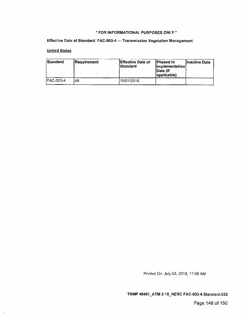
*FOR INFORMATIONAL PURPOSES ONLY*
Effective Date of Standard: FAC-003-4 — Transmission Vegetation Management
United States
Standard Requirement Effective Date of Standard
Phased In Implementation Date (if applicable)
Inactive Date
FAC-003-4 All 10/01/2016
Printed On: July 03, 2018, 11:06 AM
TNMP 48401_ATM 3-10_NERC FAC-003-4 Standard.032
Page 148 of 150
217A3 Part 2: Safety Rules for Overhead Lines
218A2
3. Identification
Supporting structures, including those on bridges, on which supply or communication conduc-tors are maintained shall be so constructed, located, marked, or numbered so as to facilitate identification by employees authorized to work thereon.
4. Attachments, decorations, and obstructions
No attachment of any kind to a supporting structure of a utility line (including lighting and metering structures) shall be allowed without the concurrence of the structure owner. Non-utility attachments shall also have concurrence of the occupant(s) of the space in which the attachment is made.
a. No attachment shall cause any portion of the resulting installation to be in noncompliance with the clearance, g-ounding, strength, or other requirements of the NESC.
b. Attachments shall neither obstruct the climbing space nor present a climbing hazard to utility personnel. Through-bolts shall be properly trimmed. Vines, nails, tacks, or other items which may interfere with climbing should be removed before climbing.
B. Unusual conductor supports
Where line conductors are attached to structures other than those used solely or principally for their support, all rules shall be complied with as far as they apply. Such additional precautions as may be deemed necessary by the administrative authority shall be taken to avoid damage to the structures or injury to the persons using them. The supporting of conductors on trees and roofs should be avoided.
C. Protection and marking of guys
1. The ground end of anchor guys exposed to pedestrian traffic shall be provided with a substan-tial and conspicuous marker,
NOTE: There is no intent to require markers at all anchor guy locations.
2. Where an anchor is located in an established parking area, the guy shall either be protected from vehicle contact or marked.
This rule does not require protection or marking of anchor guys located outside of the traveled ways of roadways or established parking areas.
NOTE: Experience has shown that it is not practical to protect guys from contact by out of control vehi-cles operating outside of established traveled ways. See Rule 231B for clearances of structures adjacent to roadways.
NOTE: Visibility of markers can be improved by the use of color or color patterns that provide contrast with the surroundings.
218. Vegetation management
A. General
1. Vegetation management should be performed around supply and communication lines as expe-rience has shown to be necessary. Vegetation that may damage ungrounded supply conductors should be pruned or removed.
NOTE : Factors to consider in determining the extent of vegetation management required include, but are not limited to: line voltage class, species growth rates and failure characteristics, right-of-way limitations, the vegetation's location in relation to the conductors, the potential combined movement of vegetation and conductors during routine winds, and sagging of conductors due to elevated temperatures or icing.
NOTE 2: It is not practical to prevent all tree-conductor contacts on overhead lines.
2. Where pruning or removal is not practical, the conductor should be separated from the tree with suitable materials or devices to avoid conductor damage by abrasion and grounding of the circuit through the tree.
83 Copyright © 2016 IEEE. All rights reserved.
TNMP 48401_ATM 3-10_NESC Section 218 - 2017.001
Page 149 of 150
218B Part 2: Safety Rules for Overhead Lines 218B
B. At line crossings, railroad crossings, limited-access highway crossings, or navigable waterways requiring crossing permits
The crossing span and the adjoining span on each side of the crossing should be kept free from over-hanging or decayed trees or limbs that otherwise might fall into the line.
84 Copyright @ 2016 IEEE. All rights reserved.
TNMP 48401_ATM 3-10_NESC Section 218 - 2017.002
Page 150 of 150


![Treatment and prevention of acute and recurrent ankle ...€¦ · Key words: Ankle injuries/therapy [MeSH], Athletic injuries/prevention & control [MeSH], Sprains and Strains/prevention](https://img.pdfslide.us/doc/110x75/5f2caa198243c2671a5f0a9e/treatment-and-prevention-of-acute-and-recurrent-ankle-key-words-ankle-injuriestherapy.jpg)