Embed Size (px)
Citation preview

EPSON®
D F X - 8 0 0 0
User’s Manual
FCC COMPLIANCE STATEMENT FOR AMERICAN USERSThis quipment has been tested and found to.&& with @te limits for a class B digitaldevice. pursuant to Part 15 of the FCC &da. ‘Yhaee limits pe designed to provide reasonableprotection against harmful interference in a residential installation. This equipment generates,uses and can radiate radio frequency energy and, if not installed and used in accordance withthe instructions, may. w,no guarantee that &&e&e ‘-YtiP
.wtorodioc~ca&uu. However, there isnot~jttapar&&rin&l#&m.Ifthisquipment
does cause harmful~@gf&+e,~.radid qr *ion *on, w&h .FM be determined byturning the equipment off and on, the user is encouraged to try to correct the interference byone or more of the following measures:. Reorient or relocate the receiving antenna.. Increase the separation between the quipment and receiver.. Connect the quipment into an outlet on a circuit different from that to which the
receiver is connected.. Consult the dealer or an experienced radio/TV technician for help.
WARNINGThe connection of a non-shielded printer interface cable to this printer will invalidate the FCCCertification of this device and may cause interfemnce levels which exceed the limitsestabliied by the FCC for this quipment. If this quipment has more than one interfaceconnector, do not leave cables connected to unused interfaces.
Seiko Epson Corporation shall not be liable against any damages or problems arisii from theuse of any options or any consumable products other than those designated as Origmal EpsonProducts or Epson Approved Products by Seiko Epson Corporation.
All rights reserved. No part of this publication may be reproduced, stored in a retrievalsystem, or transmitted, in any form or by any means, mechanical, photocopying, recording,or otherwise, without the prior written permission of Epson America, Inc. No patent liabilityis assumed with respect to the use of the information contained herein. While everyprecaution has been taken in the preparation of this book, Epson America, Inc. assumes noresponsibility for errors or omissions. Neither is any liability assumed for damages resultiqfrom the use of the information contained herein.
FOR CANADIAN USERS
This digital apparatus does not exceed the Class B limits for radio noise emissions from digitalapparatus as set out in the radio interference regulations of the Canadian Department ofCommunications.
Le pr4sent appareil num6rique n&et pas de bruits radioflectriques depassant les limitesapplicables aux appareils nun&iques de Classe B prescrites darts le r4glement sur le brouillageradidlectrique’ 6dicte par le Minis&e des Communications du Canada.
Epson and Epson ESC/P are registered trademarks of Seiko Epson Corporation.IBM is a registered trademark of International Business Machines Corporation.
Graphics created with UniPaint by Unison World Inc. and Epson JD-Graph.
Copyright 0 1989 by Epson America Inc.Torrance, California
IlWORTANT SAFETY INSTRUCTIONSReadall of these instructions and save them for later reference.
Follow all warnings and instructions marked on the product.
Unphrg this product from the wall outlet before cleaning. Do notuse liquid cleaners or aerosol cleaners. Use a damp cloth forcleaning.
1.
2.
3.
4.
5.
6.
7.
8.
9. Do not locate this product where the cord will be walked on.
Do not use this product near water.
Do not pbce this product on an unstable cart, stand, or table. Theproduct may fall, causing serious damage to the product.
Slots and openings in the cabinet and the back or bottom areprovid&d for ventilation; to ensure reliable operation of the productand to protect it from overheating, these openings must not beblocked or covered. The openings should never be blocked byplacing the product .on-a bed, sofa, rug, or other similar surface.This product should never be placed near or over a radiator or heatregister. This$rdduct’should not be placed in a built-in instAlationunless proper ventilation is provided.
This product should be operated from the type of power sourceindicated on the marking label. If you are not sure of the type ofpower available, consult your dealer or local power company.
This product is equipped with a &wire grounding-type plug, a plughaving a third (grounding) pm. This plug will only fit into agrounding-type power outlet. This is a safety feature. If you areunable to insert the plug into the outlet, contact your electrician toreplace your obsolete outlet. Do not defeat the purpose of thegrounding-type phrg.
iii
10. If an extension cord’is used with‘& product, make sure that thetotal of the ampere ratings on the products piugged into theextension cord does not exceed’the extension cord ampere rating.Also, make sure that the total .of all products plugged into thewall outlet does not exceed 15 amperes.
11. Never puih objects of any kind into this product through cabinetslots as they may touch dangerous voltage points or short out partsthat could result in a risk of fire or electric shock. Never spill liquidof any kind on the product.
12. Except as specifically explained in the User’s Manual, do notattempt to service this product yourself. Opening or removingthose covers that are marked ‘Do Not Remove” may expose you to
: dangerous voltage points or other risks. Refer all servicing ,in thosecompartments to service personnel.
13. Unplug this product from the wall outlet and refer servicing toqualified service personnel under the following conditions:
A. When the power cord or ~1% is damaged or frayed.
B. If liquid has been spilled into the product.
C. If the product has been exposed to rain or water.
D. If the product.does not operate normally when the operatinginstructions are followed. Adjust only those controls that arecovered by the operating instructions since improperadjustment of other controls may result in damage and willoften require extensive work by a qualified technician to restorethe product to normal operation.
E. If the product has been dropped or the cabinet has beendamaged.
F. If the product exhibits a distinct change in performance,indicating a need for service.
iv
Contents
About This Manual 1
Introduction 3
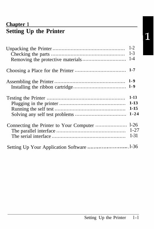
Chapter 1 Setting Up the Printer 1-1
Unpacking the Printer ................................................ 1-2Choosing a Place for the Printer .................................. 1-7Assembling the Printer ............................................... 1-9Testing the Printer .................................................... 1-13
Connecting the Printer to Your Computer ..................... 1-26Setting Up Your Application Software .......................... 1-36
Chapter 2 Paper Handling 2-1
Using the Two-Tractor System .................................... 2-2Switching between Front and Rear Tractors ................... 2-20Changing the Paper ................................................... 2-24Printing on Special Paper ........................................... 2-29
Chapter 3 Using the Printer 3-1
Operating the Control Panel ....................................... 3-2Setting the DIP Switches ............................................ 3-7Page Length ............................................................. 3-17Skip Over Perforation ............................................... 3-18Using the Paper Memory Feature ................................. 3-20Adjusting the Top of Form Position ............................. 3-33Adjusting the Printing Position .................................... 3-37Using Short Tear-Off ................................................. 3-40Selecting Typestyless ................................................... 3-43
C o n t e n t s v
Selecting an International Character Set ........................ 3-47Choosing a Character Table ........................................ 3-49Data Dump Mode ..................................................... 3-51
Chapter 4 Software and Graphics 4-1
Enhancing Your Printing ............................................ 4-2Graphics ................................................................. 4-10User-defined Characters .............................................. 4-22
Chapter 5 Using the Printer Options 5-1
Pull Tractor ............................................................. 5-2Paper Cutter ............................................................ 5-19Interface Boards ........................................................ 5-32
Chapter 6 Maintenance 6-1Cleaning the Printer .................................................. 6-2Replacing the Ribbon ................................................. 6-4Transporting the Printer ............................................. 6-9
Chapter 7 Troubleshooting 7-1
Problems and Solutions .............................................. 7-2Power Supply .......................................................... 7-3Printing ................................................................... 7-4Paper Handling ........................................................ 7-13Options ................................................................... 7-18
Chapter 8 Technical Specifications 8-1Printer Specifications ................................................. 8-2Interface Specifications ............................................... 8-11Initialization ............................................................. 8-17
vi Contents
Chapter 9 Command Summary 9-l
Using the Command Summary .................................... 9-2
Commands in Numerical Order ................................... 9-5Epson ESC/P Commands Arranged by Topic ................. 9-9IBM Emulation Mode Commands Arranged by Topic.. .... 9-41
Appendix A - l
Proportional Width Table . . . . . . . . . . . . . . . . . . . . . . . . . . . . . . . . . . . . . . . . . . A-2
Character Tables . . . . . . . . . . . . . . . . . . . . . . . . . . . . . . . . . . . . . . . . . . . . . . . . . . . . . .A-6
Glossary GL-1
Index IN-1
Contents v i i
About This Manual
This user’s manual provides fully-illustrated, step-by-stepinstructions for setting up and operating the Epson DFX-8000printer. It also includes information that you will need for yourdaily use of the printer.
Chapter 1 shows you how to unpack, set up, test, and connectthe printer. Be sure to read and follow the instructions in thischapter first. Inside the back cover of this manual areillustrations that identify the parts of the printer. You may wantto unfold the cover and refer to these illustrations as you set upand operate the printer.
Chapters 2 and 3 describe loading paper and using the printer.This information is necessary for -the day-to-day operation ofyour printer.
Chapter 4 provides, information on enhancing your printing,using software commands and graphics, and creating your ownuser-defined characters. Chapter 9 contains a summary ofprinter commands.
Chapter 7 contains troubleshooting information. If the printerdoes not operate properly or the printed results are not whatyou expect, see Chapter 7 for a list of possible problems andrecommended solutions .
Other chapters contain information on printer options, generalmaintenance, and specifications. You will also find an appendixwith reference tables, a glossary of printer terms, and an index.
At the back of this manual is a handy Quick Reference cardthat lists DIP switch settings and printer commands.
About This Manual 1
About This Manual
Conventions used in this manual
61 WARNINGS must be followed carefully to avoiddamage to your printer and computer.
CAUTIONS must be followed to ensure that yourprinter operates correctly.
Notes containimportant information and useful tips on the operationof your printer.
Where to Get HelpCustomer support and service for Epson products are provided by anetwork of authorized Epson dealers and Customer Care Centersthroughout the United States. Epson America provides productinformation and support to its dealem and Customer Care Centers.
Therefore, we a& that you contact the business where you purchasedyour Epson product to request assistance. If the people there do nothave the answer to your question, they can obtain it through our dealersupport program.
Epson is confident that this policy will provide you with the assistanceyou need. Call the Epson Consumer Information Center at1-800-922-8911 for the following:
l The location of the nearest Epson dealer
l The location of the nearest Customer Care Center
l Information on Epson User Groups.
2 About This Manual
Introduction
The Epson DFX-8000 printer is an advanced dot matrix printerdesigned for business applications. The printer combines highperformance and reliability with a wide range of-f-es, includinghigh speed printing and automatic paper handling.
Features
In addition to the high-quality printing and ease of operation youexpect from Epson printers, the DFX-8000 offers the following:
Extra-fast printing speeds of up to 1066 characters per second at 10 cpi(characters per inch) or 960 characters per second at I.2 cpi,
Two built-in push tractors (front and rear) for convenient paperhandling. This dual system lets you switch between types ofcontinuous paper quickly and.easily. The printer remembersseparate top of form positions for each tractor,
An automatic paper back-out feature that allows you to switchbetween paper loaded on the front or rear tractor withoutremoving either paper supply.
A short tear-off feature that saves paper. When a sheet ofcontinuous paper is torn off at the end of a printout, the printerreverse-feeds the remaining paper so that printing can begin atthe top of the next sheet.
A paper memory feature that produces high quality printing onyour multi-part forms by using stored paper format andthickness information to adjust the print head.
A width detection feature that automatically adjusts the printingto match the width of the paper loaded in the printer. Thisprevents the printer from printing directly on the platen, whichdamages the print head.
Introduction 3
Introduction
l A micro-adjustment feature that allows you to feed the paperforward or backward to finely adjust the top of form, loading,and short tear-off positions.
l An improved control panel design that lets you select almostany feature with a single button.
l Compatibility with the Epson ESC/P@ commands used byFX-850/1050 and DFX-5000 ,printers.
l An IBM@ emulation mode that provides compatibility withapplication programs written specifically for IBM printers.
Options
The following options are available for use with your DFX-8000printer. For detailed information on installing and using theseoptions, see Chapter 5.
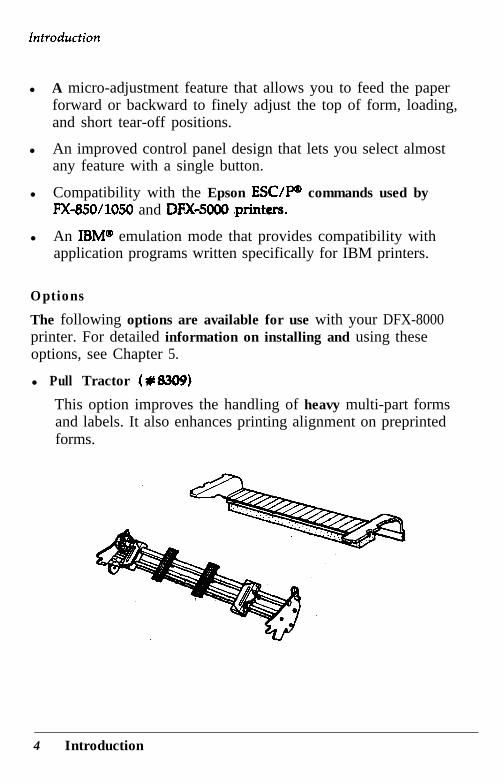
l Pull Tractor 4~8309)
This option improves the handling of heavy multi-part formsand labels. It also enhances printing alignment on preprintedforms.
4 Introduction
Introduction
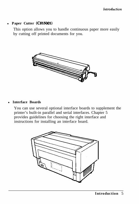
l Paper Cutter (C815001)
This option allows you to handle continuous paper more easilyby cutting off printed documents for you.
l Interface Boards
You can use several optional interface boards to supplement theprinter’s built-in parallel and serial interfaces. Chapter 5provides guidelines for choosing the right interface andinstructions for installing an interface board.
Introduction 5
Introduction
Coax and Twinax interface boards
Two interface boards (Coax and Twinax) let. you use theDFX-8000 as a local printer fez an IBM mainframe orminicomputer. These boards connect directly to the printer andallow it to function as a local IBM printer without the additionof any other circuitry or components.
6 Inkduction
Chapter 1Setting Up the Printer
Unpacking the Printer ................................................ 1-2Checking the parts ................................................. 1-3Removing the protective materials ............................. 1-4
Choosing a Place for the Printer .................................. 1-7
Assembling the Printer ............................................... l -9Installing the ribbon cartridge................................... l -9
Testing the Printer .................................................... 1-13
Plugging in the printer ............................................ 1-13Running the self test ............................................... 1-15Solving any self test problems .................................. 1-24
Connecting the Printer to Your Computer ..................... l-26The parallel interface .............................................. 1-27The serial interface ................................................. 1-31
Setting Up Your Application Software . . . . . . . . . . . . . . . . . . . . . . . . . . l-36
Setting Up the Printer l - l
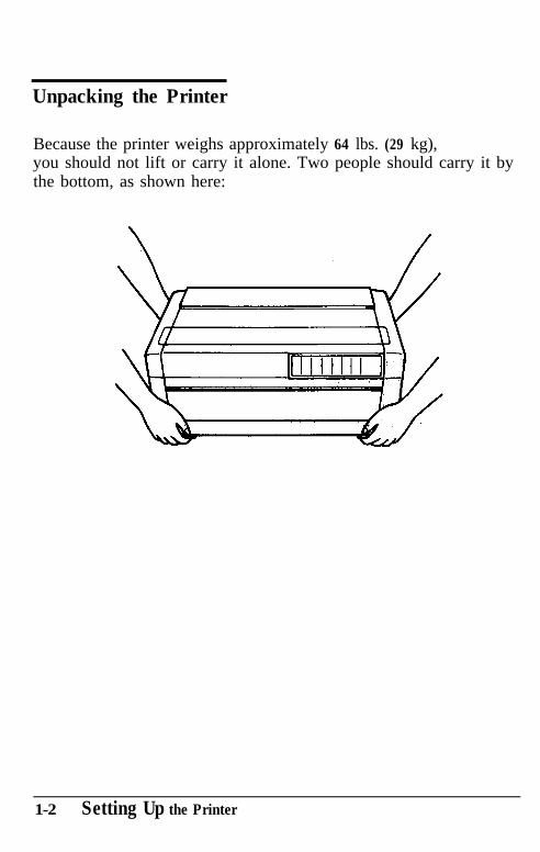
Unpacking the Printer
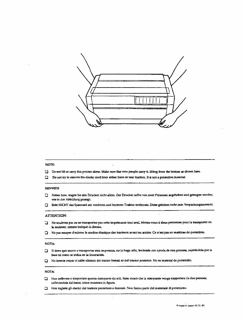
Because the printer weighs approximately 64 lbs. (29 kg),you should not lift or carry it alone. Two people should carry it bythe bottom, as shown here:
1-2 Setting Up the Printer
Unpacking the Printer
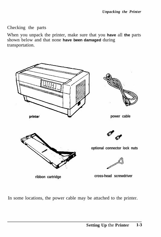
Checking the parts
When you unpack the printer, make sure that you have all the partsshown below and that none have been damaged duringtransportation.
power cable
optional connector lock nuts
ribbon cartridge cross-head screwdriver
In some locations, the power cable may be attached to the printer.
Setting Up the Printer 1-3
Unpacking the Printer
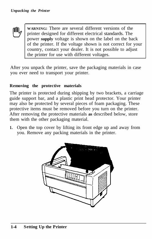
WARNING: There are several different versions of theprinter designed for different electrical standards. Thepower supply voltage is shown on the label on the backof the printer. If the voltage shown is not correct for yourcountry, contact your dealer. It is not possible to adjustthe printer for use with different voltages.
After you unpack the printer, save the packaging materials in caseyou ever need to transport your printer.
Removing the protective materials
The printer is protected during shipping by two brackets, a carriageguide support bar, and a plastic print head protector. Your printermay also be protected by several pieces of foam packaging. Theseprotective items must be removed before you turn on the printer.After removing the protective materials as described below, storethem with the other packaging material.
1. Open the top cover by lifting its front edge up and away fromyou. Remove any packing materials in the printer.
1-4 Setting Up the Printer
Unpacking the Printer
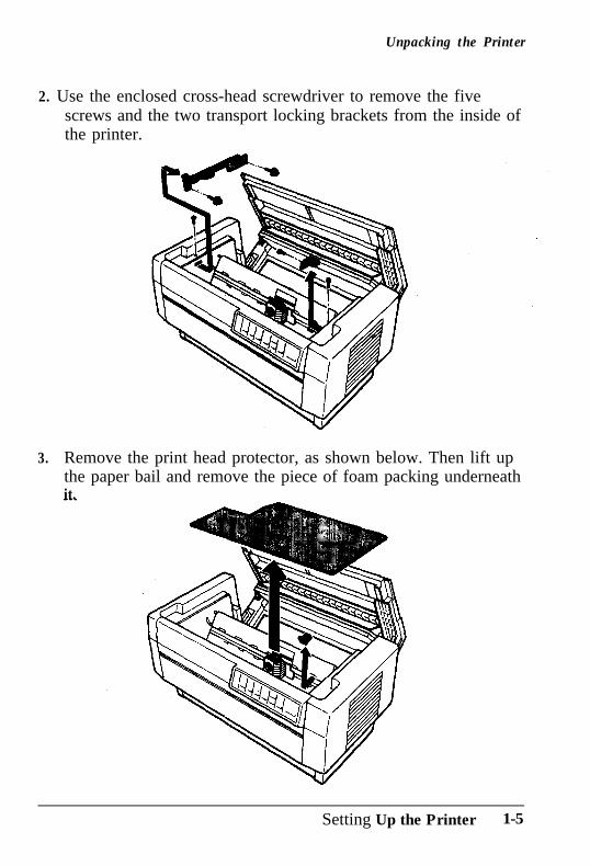
2. Use the enclosed cross-head screwdriver to remove the fivescrews and the two transport locking brackets from the inside ofthe printer.
3. Remove the print head protector, as shown below. Then lift upthe paper bail and remove the piece of foam packing underneathit.
Setting Up the Printer 1-5
Unpacking the Printer
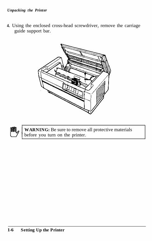
4. Using the enclosed cross-head screwdriver, remove the carriageguide support bar.
WARNING: Be sure to remove all protective materialsbefore you turn on the printer.
1-6 Setting Up the Printer
Choosing a Place for the Printer
When you select a location for your printer, keep the following inmind:
l Place the printer on a flat, stable surface.
l Place the printer close enough to the computer for the printercable to reach.
l Leave plenty of room around the printer for your front and rearstacks of continuous paper as well as your printed output.
l Use a grounded outlet; do not use an adapter plug.
WARNING: Avoid locations that are subject to directsunlight, excessive heat, moisture, or dust.
Avoid using electrical outlets that are controlled by wallswitches or automatic timers. Accidental interruption of powercan wipe out information in your computer’s and your printer’smemory.
Avoid using outlets on the same circuit with large motors orelectrical appliances that might cause fluctuations in line voltage.
Keep the entire computer system away from potential sources ofelectromagnetic interference; such as loudspeakers or the baseunits of cordless telephones.
Setting Up the Printer 1-7
Choosing a Place for the Printer
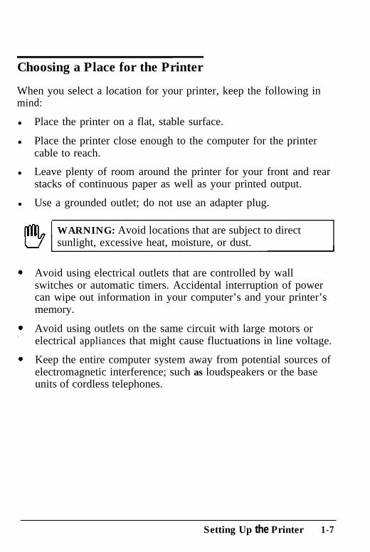
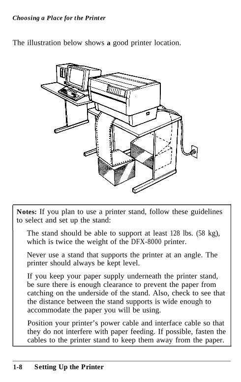
The illustration below shows a good printer location.
Notes: If you plan to use a printer stand, follow these guidelinesto select and set up the stand:
The stand should be able to support at least 128 lbs. (58 kg),which is twice the weight of the DFX-8000 printer.
Never use a stand that supports the printer at an angle. Theprinter should always be kept level.
If you keep your paper supply underneath the printer stand,be sure there is enough clearance to prevent the paper fromcatching on the underside of the stand. Also, check to see thatthe distance between the stand supports is wide enough toaccommodate the paper you will be using.
Position your printer’s power cable and interface cable so thatthey do not interfere with paper feeding. If possible, fasten thecables to the printer stand to keep them away from the paper.
1-8 Setting Up the Printer
Assembling the Printer
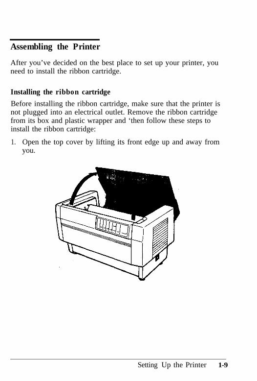
After you’ve decided on the best place to set up your printer, youneed to install the ribbon cartridge.
Installing the ribbon cartridge
Before installing the ribbon cartridge, make sure that the printer isnot plugged into an electrical outlet. Remove the ribbon cartridgefrom its box and plastic wrapper and ‘then follow these steps toinstall the ribbon cartridge:
1. Open the top cover by lifting its front edge up and away fromyou.
Setting Up the Printer 1-9
Assembling the Printer
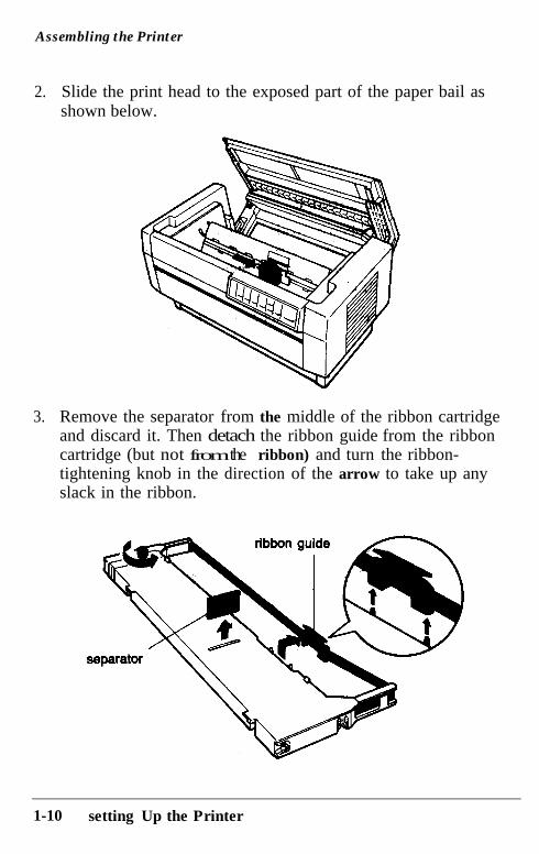
2.. Slide the print head to the exposed part of the paper bail asshown below.
3.. Remove the separator from the middle of the ribbon cartridgeand discard it. Then detach the ribbon guide from the ribboncartridge (but not from the ribbon) and turn the ribbon-tightening knob in the direction of the arrow to take up anyslack in the ribbon.
1-10 setting Up the Printer
Assembling the Printer
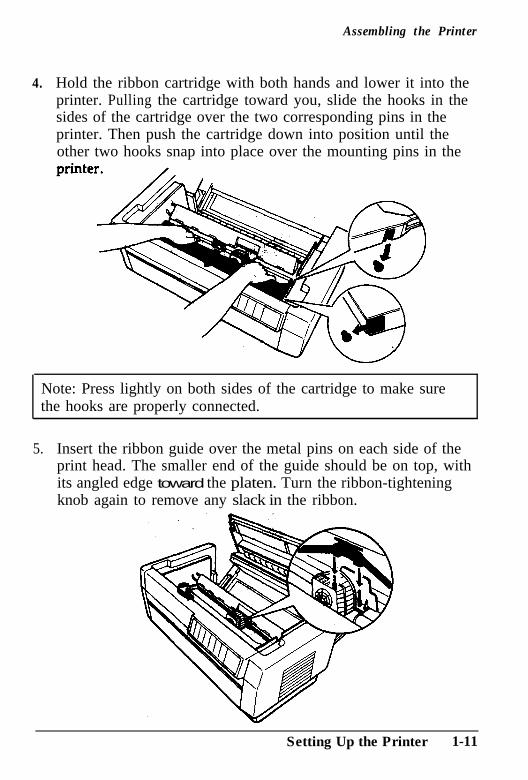
4. Hold the ribbon cartridge with both hands and lower it into theprinter. Pulling the cartridge toward you, slide the hooks in thesides of the cartridge over the two corresponding pins in theprinter. Then push the cartridge down into position until theother two hooks snap into place over the mounting pins in the
Note: Press lightly on both sides of the cartridge to make surethe hooks are properly connected.
5.. Insert the ribbon guide over the metal pins on each side of theprint head. The smaller end of the guide should be on top, withits angled edge toward the platen. Turn the ribbon-tighteningknob again to remove any slack in the ribbon.
Setting Up the Printer 1-11
Assembling the Printer
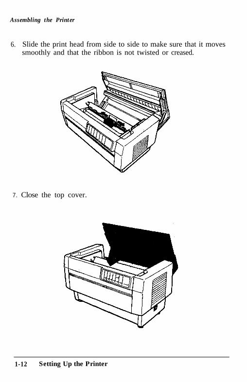
6. Slide the print head from side to side to make sure that it movessmoothly and that the ribbon is not twisted or creased.
7. Close the top cover.
1-12 Setting Up the Printer
Testing the Printer
Now that your printer is fully assembled, you can use its built-inself test function to be sure the printer is working correctly beforeyou connect it to a computer. You should perform this test to makesure that your printer was not damaged during shipping and thatthe ribbon is correctly installed.
Before performing the self test, you need to plug in your printer andload paper.
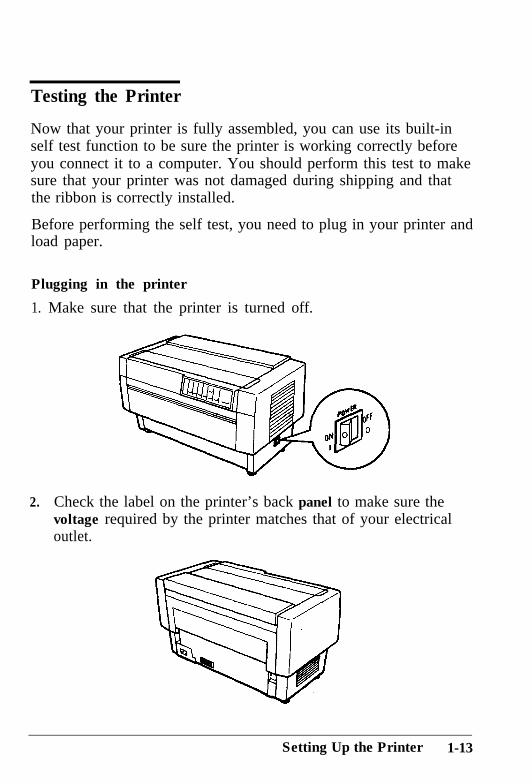
Plugging in the printer
1. Make sure that the printer is turned off.
2. Check the label on the printer’s back panel to make sure thevoltage required by the printer matches that of your electricaloutlet.
Setting Up the Printer 1-13
Testing the Printer
r!!!b
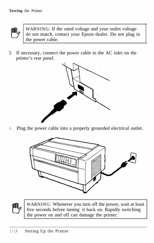
WARNING: If the rated voltage and your outlet voltagedo not match, contact your Epson dealer. Do not plug inthe power cable.
3. If necessary, connect the power cable to the AC inlet on theprinter’s rear panel.
4. Plug the power cable into a properly grounded electrical outlet.
!!9 WARNING: Whenever you turn off the power, wait at leastfive seconds before turning it back on. Rapidly switchingthe power on and off can damage the printer.
1-14 Setting Up the Printer
Testing the Printer
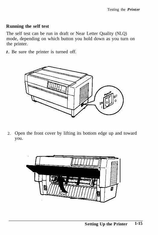
Running the self test
The self test can be run in draft or Near Letter Quality (NLQ)mode, depending on which button you hold down as you turn onthe printer.
1. Be sure the printer is turned off.
2.. Open the front cover by lifting its bottom edge up and towardyou.
Setting Up the Printer 1-15
Testing the Printer
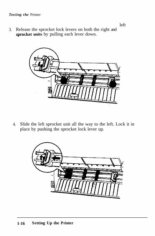
3. Release the sprocket lock levers on both the right andsprocket units by pulling each lever down.
left
4.. Slide the left sprocket unit all the way to the left. Lock it inplace by pushing the sprocket lock lever up.
1-16 Setting Up the Printer
Testing the Printer
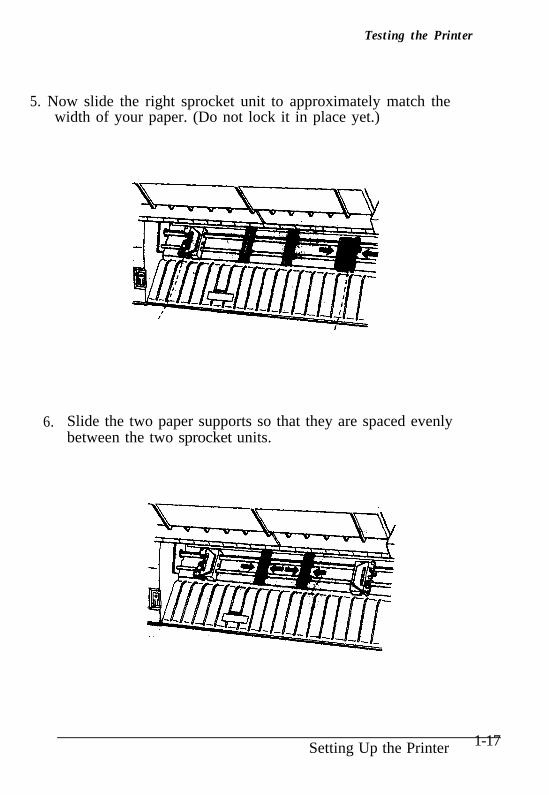
5. Now slide the right sprocket unit to approximately match thewidth of your paper. (Do not lock it in place yet.)
6.. Slide the two paper supports so that they are spaced evenlybetween the two sprocket units.
Setting Up the Printer 1-17
Testing the Printer
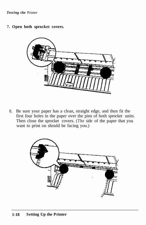
7. Open both sprocket covers.
8.. Be sure your paper has a clean, straight edge, and then fit thefirst four holes in the paper over the pins of both sprocket units.Then close the sprocket covers. (The side of the paper that youwant to print on should be facing you.)
1-18 Setting Up the Printer
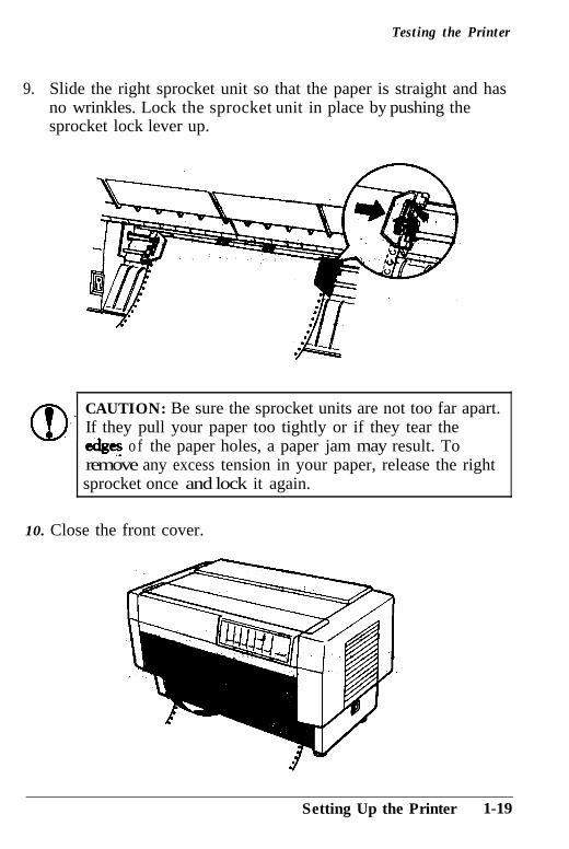
Testing the Printer
9.. Slide the right sprocket unit so that the paper is straight and hasno wrinkles. Lock the sprocket unit in place by pushing thesprocket lock lever up.
a-
CAUTION: Be sure the sprocket units are not too far apart.
lIf they pull your paper too tightly or if they tear theed&s o f the paper holes, a paper jam may result. Toremove any excess tension in your paper, release the right
sprocket once and lock it again.
10. Close the front cover.
Setting Up the Printer 1-19
Testing the Printer
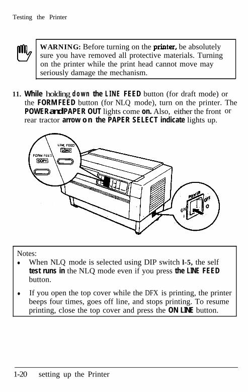
WARNING: Before turning on the printer, be absolutelysure you have removed all protective materials. Turningon the printer while the print head cannot move mayseriously damage the mechanism.
11. While holding d o w n the L I N E FEED button (for draft mode) orthe FORM FEED button (for NLQ mode), turn on the printer. ThePOWER and PAPER OUT lights come on. Also, either the frontrear tractor arrow o n the PAPER SELECT indicate lights up.
or
Notes:l When NLQ mode is selected using DIP switch l-5, the self
test runs in the NLQ mode even if you press the LINE FEEDbutton.
l If you open the top cover while the DFX is printing, the printerbeeps four times, goes off line, and stops printing. To resumeprinting, close the top cover and press the ON LINE button.
1-20 setting up the Printer
Testing the Printer
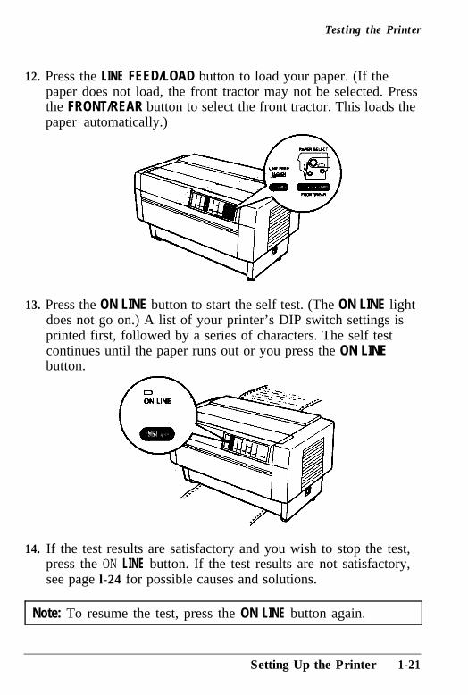
12. Press the LINE FEED/LOAD button to load your paper. (If thepaper does not load, the front tractor may not be selected. Pressthe FRONT/REAR button to select the front tractor. This loads thepaper automatically.)
13. Press the ON LINE button to start the self test. (The ON LINE lightdoes not go on.) A list of your printer’s DIP switch settings isprinted first, followed by a series of characters. The self testcontinues until the paper runs out or you press the ON LINEbutton.
14. If the test results are satisfactory and you wish to stop the test,press the ON LINE button. If the test results are not satisfactory,see page l-24 for possible causes and solutions.
Note: To resume the test, press the ON LINE button again.
Setting Up the Printer 1-21
Testing the Printer
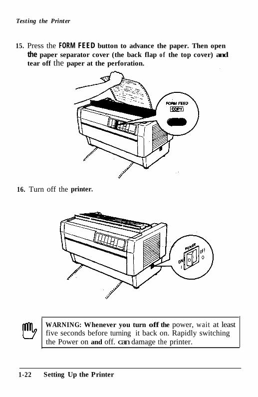
15. Press the FORM FEED button to advance the paper. Then openthe paper separator cover (the back flap of the top cover) andtear off the paper at the perforation.
16. Turn off thee printer.
WARNING: Whenever you turn off the power, wait at leastfive seconds before turning it back on. Rapidly switchingthe Power on and off. can damage the printer.
1-22 Setting Up the Printer
Testing the Printer
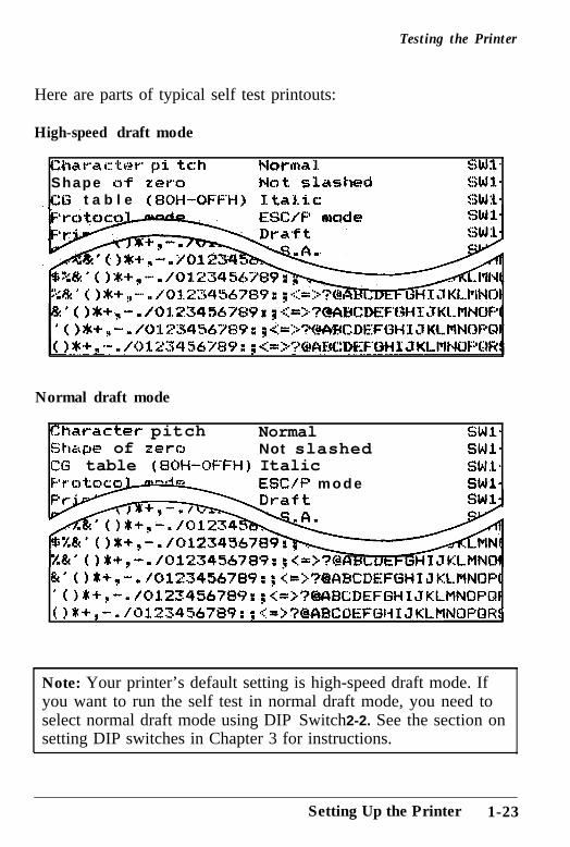
Here are parts of typical self test printouts:
High-speed draft mode
Uw~~~ar::tc~r p:i. tc:h l4wvnal cs W1.Shape a9 z e I”0 Nat. slashed ZW1.
t a b l e (#OH-OFFH) T. tnli.c GWL-ESC/F mode
Normal draft mode
Character pitch NormalShal:)e of zern Not slashedCG table (SOH-OFFH) Italic
ESC/F m o d e
SWl*SWl*SWl*SWl*
rox+,- ./0123456789: ; &~?IABCDEFGHIJKLMNOP[‘O#+,-. /0123456789r;<=>?CBCDEFGHIJKLMNOPOf( If+,-./0123456789: ;~<=>?@ABCWEFGtiIJKLMNOFQR~
Note: Your printer’s default setting is high-speed draft mode. Ifyou want to run the self test in normal draft mode, you need toselect normal draft mode using DIP Switch 2-2. See the section onsetting DIP switches in Chapter 3 for instructions.
Setting Up the Printer 1-23
Testing the Printer
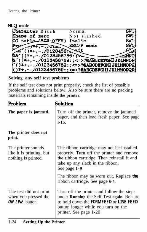
NLQ modecharacter D i t c h Normal
N o t s l a s h e d
Solving any self test problems
If the self test does not print properly, check the list of possibleproblems and solutions below. Also be sure there are no packingmaterials remaining inside the printer.
The paper is jammed.
The printer does notprint.
The printer soundslike it is printing, butnothing is printed.
The test did not printwhen you pressed theON LINE button.
Turn off the printer, remove the jammedpaper, and then load fresh paper. See pagel-15.
The ribbon cartridge may not be installedproperly. Turn off the printer and removethe ribbon cartridge. Then reinstall it andtake up any slack in the ribbon.See page 1-9
The ribbon may be worn out. Replace theribbon cartridge. See page 6-4.
Turn off the printer and follow the stepsunder Running the Self Test again. Be sureto hold down the FORM FEED or LINE FEEDbutton longer while you turn on theprinter. See page 1-20
1-24 Setting Up the Printer
Testing the Printer
Problem Solution
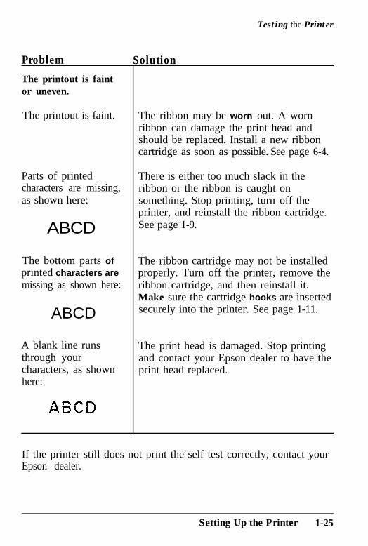
The printout is faintor uneven.
The printout is faint.
Parts of printedcharacters are missing,as shown here:
ABCD
The bottom parts ofprinted characters aremissing as shown here:
ABCD
A blank line runsthrough yourcharacters, as shownhere:
The ribbon may be worn out. A wornribbon can damage the print head andshould be replaced. Install a new ribboncartridge as soon as possible. See page 6-4.
There is either too much slack in theribbon or the ribbon is caught onsomething. Stop printing, turn off theprinter, and reinstall the ribbon cartridge.See page 1-9.
The ribbon cartridge may not be installedproperly. Turn off the printer, remove theribbon cartridge, and then reinstall it.Make sure the cartridge hooks are insertedsecurely into the printer. See page 1-11.
The print head is damaged. Stop printingand contact your Epson dealer to have theprint head replaced.
If the printer still does not print the self test correctly, contact yourEpson dealer.
Setting Up the Printer 1-25
Connecting the Printer to Your Computer
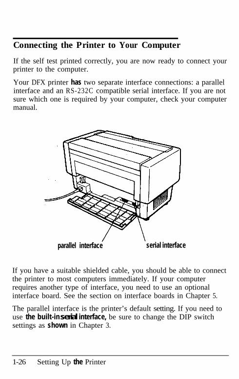
If the self test printed correctly, you are now ready to connect yourprinter to the computer.
Your DFX printer has two separate interface connections: a parallelinterface and an RS-232C compatible serial interface. If you are notsure which one is required by your computer, check your computermanual.
parallel interface serial interface
If you have a suitable shielded cable, you should be able to connectthe printer to most computers immediately. If your computerrequires another type of interface, you need to use an optionalinterface board. See the section on interface boards in Chapter 5.
The parallel interface is the printer’s default setting. If you need touse the built-in serial interface, be sure to change the DIP switchsettings as shown in Chapter 3.
1-26 Setting Up the Printer
Connecting the Printer to Your Computer
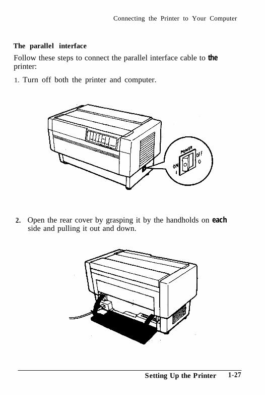
The parallel interface
Follow these steps to connect the parallel interface cable to theprinter:
1. Turn off both the printer and computer.
2. Open the rear cover by grasping it by the handholds on eachside and pulling it out and down.
Setting Up the Printer 1-27
Connecting the Printer to Your Computer
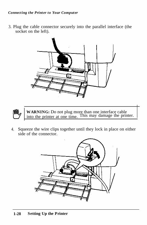
3. Plug the cable connector securely into the parallel interface (thesocket on the left).
WARNING: Do not plug more than one interface cableinto the printer at one time. This may damage the printer.
4. Squeeze the wire clips together until they lock in place on eitherside of the connector.
1-28 Setting Up the Printer
Connecting the Printer to Your Computer
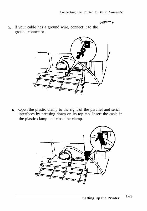
5. If your cable has a ground wire, connect it to the Pnter s
ground connector.
6. Open the plastic clamp to the right of the parallel and serialinterfaces by pressing down on its top tab. Insert the cable inthe plastic clamp and close the clamp.
Setting Up the Printer 1-29
Connecting the Printer to Your Computer
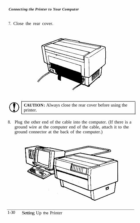
7. Close the rear cover.
CAUTION: Always close the rear cover before using theprinter.
8. Plug the other end of the cable into the computer. (If there is aground wire at the computer end of the cable, attach it to theground connector at the back of the computer.)
1-30 Setting Up the Printer
Connecting the Printer to Your Computer
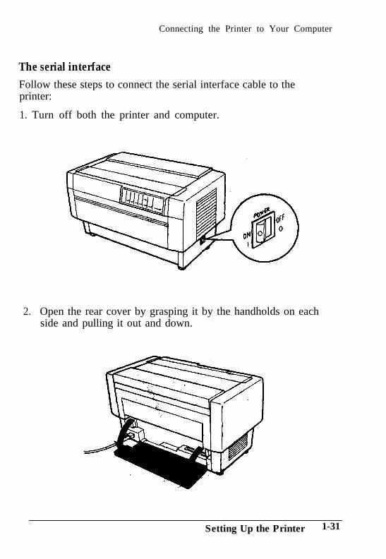
The serial interfaceFollow these steps to connect the serial interface cable to theprinter:
1. Turn off both the printer and computer.
2.. Open the rear cover by grasping it by the handholds on eachside and pulling it out and down.
Setting Up the Printer 1-31
Connecting the Printer to Your Computer
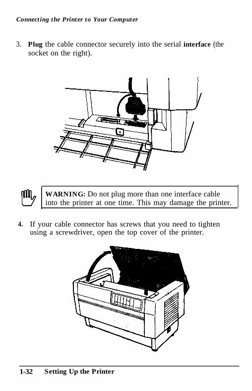
3.. Plug the cable connector securely into the serial interface (thesocket on the right).
WARNING: Do not plug more than one interface cableinto the printer at one time. This may damage the printer.
4. If your cable connector has screws that you need to tightenusing a screwdriver, open the top cover of the printer.
1-32 Setting Up the Printer
Connecting the Printer to Your Computer
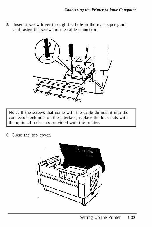
5. Insert a screwdriver through the hole in the rear paper guideand fasten the screws of the cable connector.
Note: If the screws that come with the cable do not fit into theconnector lock nuts on the interface, replace the lock nuts withthe optional lock nuts provided with the printer.
6. Close the top cover.
Setting Up the Printer 1-33
Connecting the Printer to Your Computer
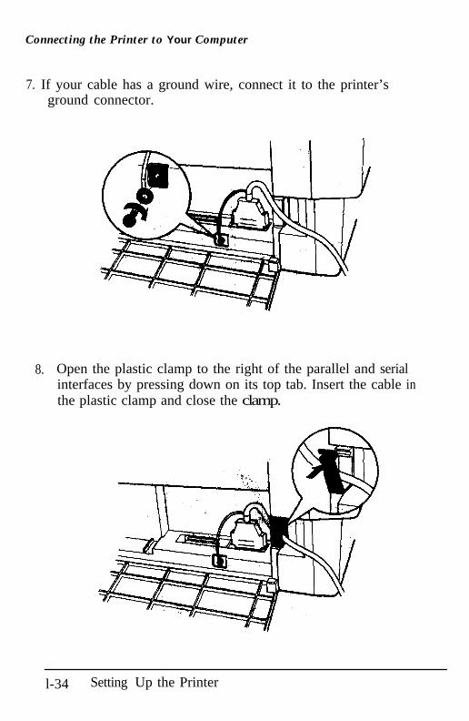
7. If your cable has a ground wire, connect it to the printer’sground connector.
8. Open the plastic clamp to the right of the parallel and serialinterfaces by pressing down on its top tab. Insert the cable inthe plastic clamp and close the clamp.
l-34 Setting Up the Printer
Connecting the Printer to Your Computer
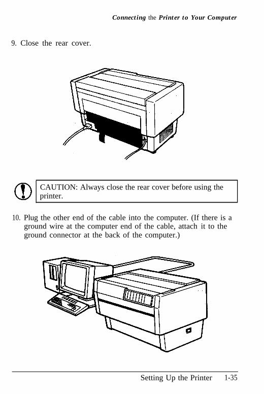
9. Close the rear cover.
CAUTION: Always close the rear cover before using theprinter.
10. Plug the other end of the cable into the computer. (If there is aground wire at the computer end of the cable, attach it to theground connector at the back of the computer.)
Setting Up the Printer 1-35
Setting Up Your Application Software
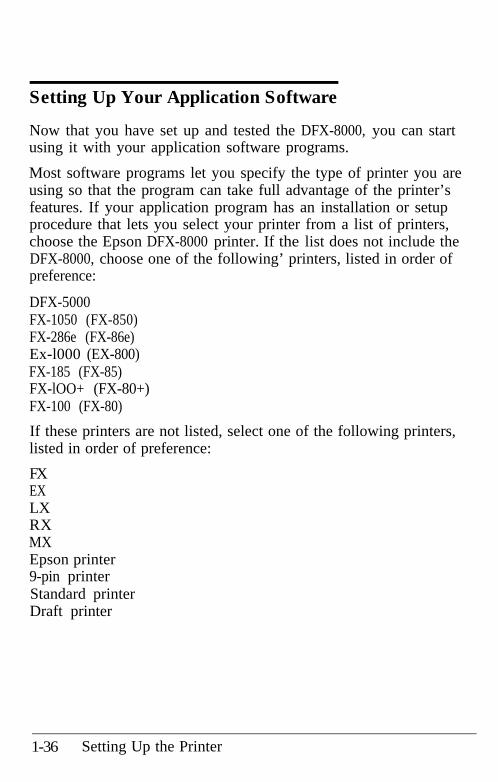
Now that you have set up and tested the DFX-8000, you can startusing it with your application software programs.
Most software programs let you specify the type of printer you areusing so that the program can take full advantage of the printer’sfeatures. If your application program has an installation or setupprocedure that lets you select your printer from a list of printers,choose the Epson DFX-8000 printer. If the list does not include theDFX-8000, choose one of the following’ printers, listed in order ofpreference:
DFX-5000FX-1050 (FX-850)FX-286e (FX-86e)Ex-l000 (EX-800)FX-185 (FX-85)FX-lOO+ (FX-80+)FX-100 (FX-80)
If these printers are not listed, select one of the following printers,listed in order of preference:
FXEXLXRXMXEpson printer9-pin printerStandard printerDraft printer
1-36 Setting Up the Printer
Setting Up Your Application Software
If you plan to use IBM emulation mode, select one of the followingprinters, listed in order of preference:
IBM Proprinter XLIBM Graphics printerIBM Printer
Note: To use all the features of the DFX-8000, it is best to use aprogram with the DFX-8000 on its menu. If your software programdoes not list the DFX-8000, contact the software manufacturer tosee if an update is available.
Setting Up the Printer 1-37
Paper Handling
Using the Two-Tractor System .................................... 2-2Positioning the paper supply .................................... 2-2Loading paper onto the front tractor ......................... 2-4Loading paper onto the rear tractor ........................... 2-11
Switching between Front and Rear Tractors ................... 2-20
Changing the paper .................................................. 2-24
Printing on Special Paper ........................................... 2-29Copy mode........................................................... 2-29Multi-part forms .................................................... 2-30Labelss .................................................................. 2-32
P a p e r Handling 2-l
Using the Two-Tractor System
The DFX-8000’s paper handling system consists of a front and a rearpush tractor. Both tractors are easy to load and operate, and bothaccommodate a wide variety of paper types, including labels andmulti-part forms. The printer automatically adjusts to the thicknessof your loaded paper, so you don’t need to set the paper thicknessmanually. You can use any width continuous paper, from 4 inches(101 mm) to 16 inches (406 mm) wide. Your printer also senses thepaper width automatically.
If you plan to use more than two types of paper, it is best to loadthe paper you use most often onto the rear tractor. That way youcan use the front tractor, which is easier to reach, for paper youchange more often.
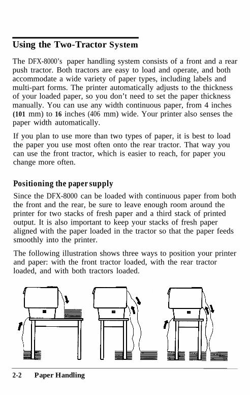
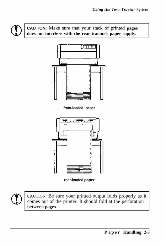
Positioning the paper supplySince the DFX-8000 can be loaded with continuous paper from boththe front and the rear, be sure to leave enough room around theprinter for two stacks of fresh paper and a third stack of printedoutput. It is also important to keep your stacks of fresh paperaligned with the paper loaded in the tractor so that the paper feedssmoothly into the printer.
The following illustration shows three ways to position your printerand paper: with the front tractor loaded, with the rear tractorloaded, and with both tractors loaded.
2-2 Paper Handling
Using the Two-Tractor System
CAUTION: Make sure that your stack of printed pagesdoes not interfere with the rear tractor’s paper supply.
front-loaded paper
rear-loaded paper
CAUTION: Be sure your printed output folds properly as itcomes out of the printer. It should fold at the perforationbetween pages.
P a p e r Handling 2-3
Using the Two-Tractor System
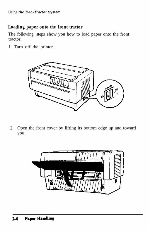
Loading paper onto the front tractorThe foIlowing steps show you how to load paper onto the fronttractor.
1. Turn off the printer.
2.. Open the front cover by lifting its bottom edge up and towardyou.
Using the Two-Tractor System
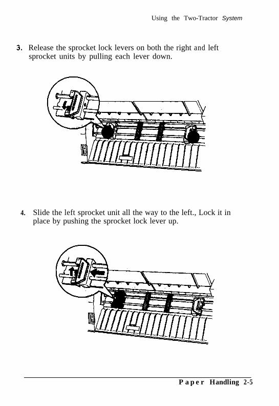
Release the sprocket lock levers on both the right and leftsprocket units by pulling each lever down.
4. Slide the left sprocket unit all the way to the left., Lock it inplace by pushing the sprocket lock lever up.
P a p e r Handling 2-5
Using the Two-Tractor System
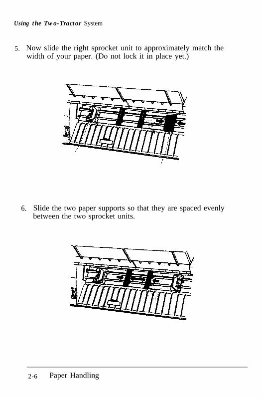
5.. Now slide the right sprocket unit to approximately match thewidth of your paper. (Do not lock it in place yet.)
6.. Slide the two paper supports so that they are spaced evenlybetween the two sprocket units.
2-6 Paper Handling
Using the Two-Tractor System
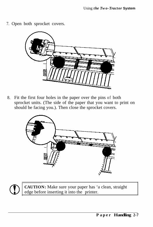
7. Open both sprocket covers.
8.. Fit the first four holes in the paper over the pins o f bothsprocket units. (The side of the paper that you want to print onshould be facing you.). Then close the sprocket covers.
CAUTION: Make sure your paper has ‘a clean, straightedge before inserting it into the printer.
P a p e r Handling 2-7
Using the Two-Tractor System
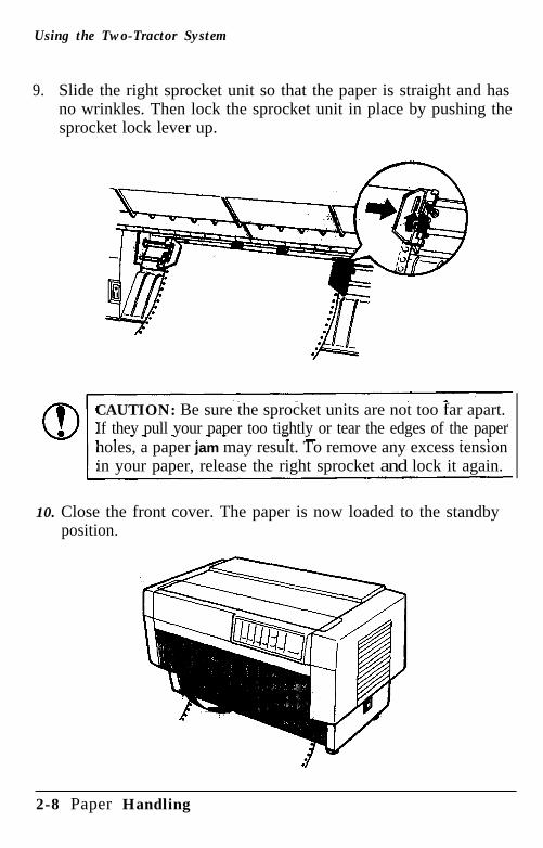
9.. Slide the right sprocket unit so that the paper is straight and hasno wrinkles. Then lock the sprocket unit in place by pushing thesprocket lock lever up.
CAUTION: Be sure the sprocket units are not too far apart.If they pull your paper too tightly or tear the edges of the paperholes, a paper jam may result. To remove any excess tensionin your paper, release the right sprocket and lock it again.
10. Close the front cover. The paper is now loaded to the standbyposition.
2-8 Paper Handling
Using the Two-Tractor System
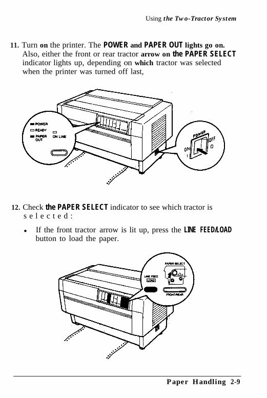
11. Turn on the printer. The POWER and PAPER OUT lights go on.Also, either the front or rear tractor arrow on the PAPER SELECTindicator lights up, depending on which tractor was selectedwhen the printer was turned off last,
12. Check the PAPER SELECT indicator to see which tractor iss e l e c t e d :
l If the front tractor arrow is lit up, press the LINE FEED/LOADbutton to load the paper.
Paper Handling 2-9
Using the Two-Tractor System
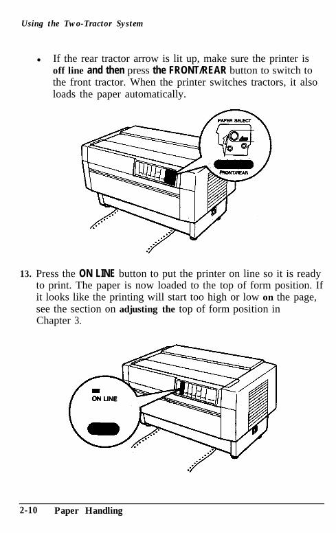
l If the rear tractor arrow is lit up, make sure the printer isoff line and then press the FRONT/REAR button to switch tothe front tractor. When the printer switches tractors, it alsoloads the paper automatically.
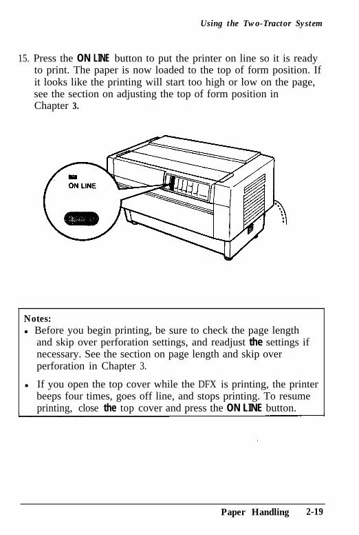
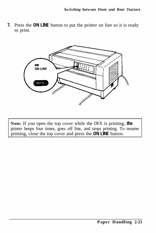
13. Press the ON LINE button to put the printer on line so it is readyto print. The paper is now loaded to the top of form position. Ifit looks like the printing will start too high or low on the page,see the section on adjusting the top of form position inChapter 3.
2-10 Paper Handling
Using the Two-Tractor System
Notes:l Before you begin printing, be sure to check the page length
and skip over perforation settings, and readjust the settings ifnecessary. See the sections on page length and skip overperforation in Cha#qr 3.
l If you open the top cover while the DFX is printing, the printerbeeps four times, goes off line, and stops printing. To resumeprinting, close the top cover and press the ON LINE button.
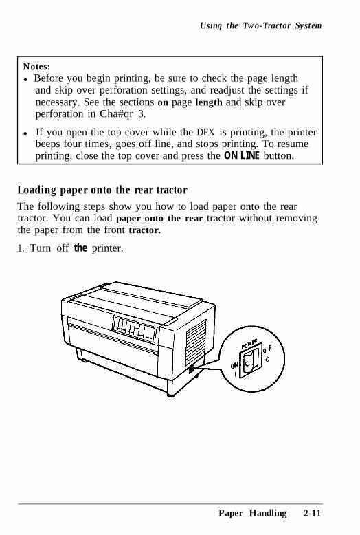
Loading paper onto the rear tractorThe following steps show you how to load paper onto the reartractor. You can load paper onto the rear tractor without removingthe paper from the front tractor.
1. Turn off the printer.
Paper Handling 2-11
Using the Two-Tractor System
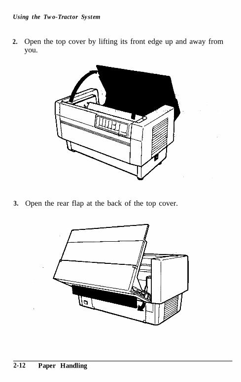
2. Open the top cover by lifting its front edge up and away fromyou.
3. Open the rear flap at the back of the top cover.
2-12 Paper Handling
Using the Two-Tractor System
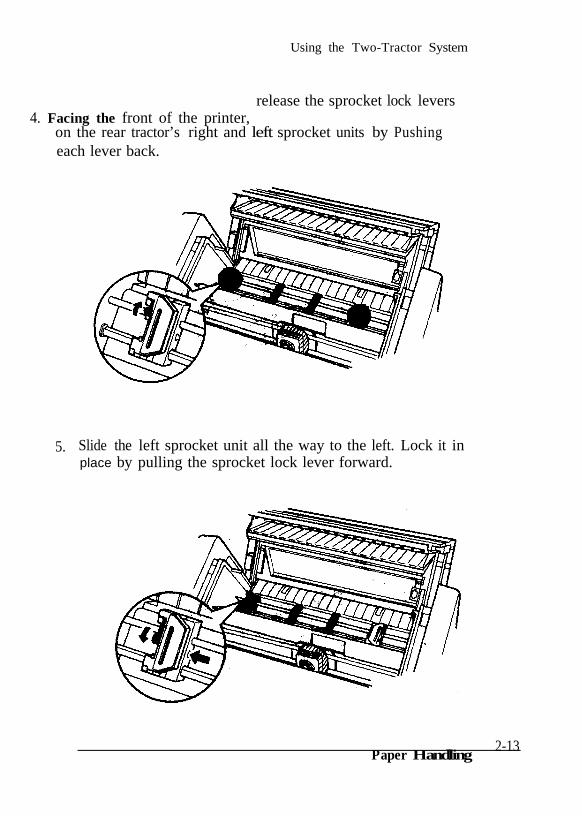
4. Facing the front of the printer,release the sprocket lock levers
on the rear tractor’s right and left sprocket units by Pushingeach lever back.
5. Slide the left sprocket unit all the way to the left. Lock it inplace by pulling the sprocket lock lever forward.
Paper Handling2-13
Using the Two-Tractor System
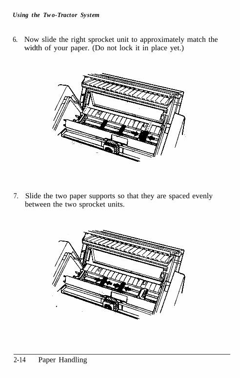
6. Now slide the right sprocket unit to approximately match thewidth of your paper. (Do not lock it in place yet.)
7. Slide the two paper supports so that they are spaced evenlybetween the two sprocket units.
2-14 Paper Handling
Using the Two-Tractor System
8. Open both sprocket covers.
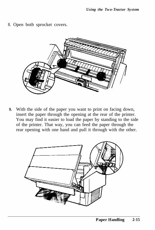
9. With the side of the paper you want to print on facing down,insert the paper through the opening at the rear of the printer.You may find it easier to load the paper by standing to the sideof the printer. That way, you can feed the paper through therear opening with one hand and pull it through with the other.
Paper Handling 2-15
Using the Two-Tractor System
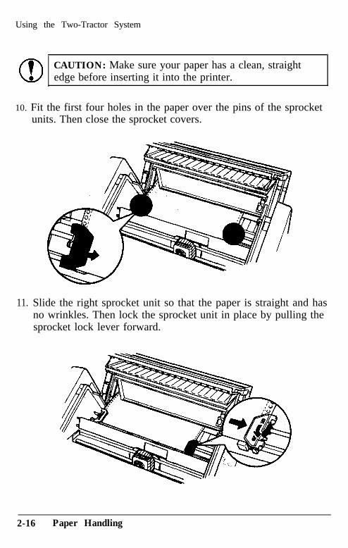
CAUTION: Make sure your paper has a clean, straightedge before inserting it into the printer.
10. Fit the first four holes in the paper over the pins of the sprocketunits. Then close the sprocket covers.
11. Slide the right sprocket unit so that the paper is straight and hasno wrinkles. Then lock the sprocket unit in place by pulling thesprocket lock lever forward.
2-16 Paper Handling
Using the Two-Tractor System
CAUTION: Be sure the sprocket units are not too far apart.If they pull your paper too tightly or tear the edges of the paperholes, a paper jam may result. To remove any excess tensionin your paper, release the right sprocket and lock it again.
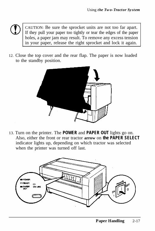
12. Close the top cover and the rear flap. The paper is now loadedto the standby position.
13. Turn on the printer. The POWER and PAPER OUT lights go on.Also, either the front or rear tractor arrow on the PAPER SELECTindicator lights up, depending on which tractor was selectedwhen the printer was turned off last.
Paper Handling 2-17
Using the Two-Tractor System
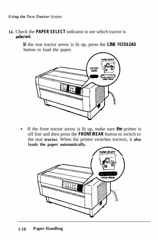
14.. Check the PAPER SELECT indicator to see which tractor iss e l e c t eC U .
TC 11’ the rear tractor arrow is lit up, press the LINE FEED/LOAD
button to load the paper.
l If the front tractor arrow is lit up, make sure the printer isoff line and then press the FRONT/REAR button to switch tothe rear tractor. When the printer switches tractors, it also loads the paper automatically.
ha
2-18 Paper Handling
Using the Two-Tractor System
15. Press the ON LINE button to put the printer on line so it is readyto print. The paper is now loaded to the top of form position. Ifit looks like the printing will start too high or low on the page,see the section on adjusting the top of form position inChapter 3.
Notes:l Before you begin printing, be sure to check the page length
and skip over perforation settings, and readjust the settings ifnecessary. See the section on page length and skip overperforation in Chapter 3.
l If you open the top cover while the DFX is printing, the printerbeeps four times, goes off line, and stops printing. To resumeprinting, close the top cover and press the ON LINE button.
Paper Handling 2-19
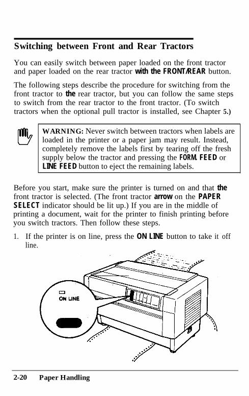
Switching between Front and Rear Tractors
You can easily switch between paper loaded on the front tractorand paper loaded on the rear tractor with the FRONT/REAR button.
The following steps describe the procedure for switching from thefront tractor to the rear tractor, but you can follow the same stepsto switch from the rear tractor to the front tractor. (To switchtractors when the optional pull tractor is installed, see Chapter 5.)
!!!!!b
WARNING: Never switch between tractors when labels areloaded in the printer or a paper jam may result. Instead,completely remove the labels first by tearing off the freshsupply below the tractor and pressing the FORM. FEED orLINE FEED button to eject the remaining labels.
Before you start, make sure the printer is turned on and that thefront tractor is selected. (The front tractor arrow on the PAPERSELECT indicator should be lit up.) If you are in the middle ofprinting a document, wait for the printer to finish printing beforeyou switch tractors. Then follow these steps.
1. If the printer is on line, press the ON LINE button to take it offline.
2-20 Paper Handling
Switching between Front and Rear Tractors
2.
3.
4.
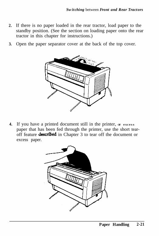
If there is no paper loaded in the rear tractor, load paper to thestandby position. (See the section on loading paper onto the reartractor in this chapter for instructions.)
Open the paper separator cover at the back of the top cover.
If you have a printed document still in the printer, OF excesspaper that has been fed through the printer, use the short tear-off feature de&&d in Chapter 3 to tear off the document orexcess paper.
Paper Handling 2-21
Switching between Front and Rear Tractors
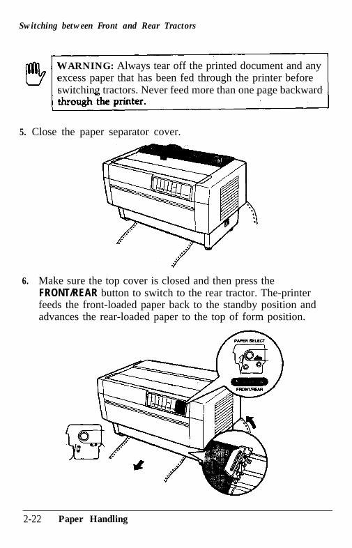
WARNING: Always tear off the printed document and anyexcess paper that has been fed through the printer beforeswitching tractors. Never feed more than one page backward
5. Close the paper separator cover.
6. Make sure the top cover is closed and then press theFRONT/REAR button to switch to the rear tractor. The-printerfeeds the front-loaded paper back to the standby position andadvances the rear-loaded paper to the top of form position.
2-22 Paper Handling
Switching between Front and Rear Tractors
7.. Press the ON LINE button to put the printer on line so it is readyto print.
Note: If you open the top cover while the DFX is printing, theprinter beeps four times, goes off line, and stops printing. To resumeprinting, close the top cover and press the ON LINE button.
Paper Handling 2-23
Changing the Paper
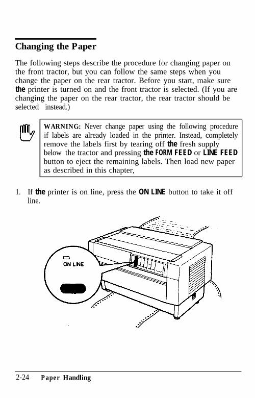
The following steps describe the procedure for changing paper onthe front tractor, but you can follow the same steps when youchange the paper on the rear tractor. Before you start, make surethe printer is turned on and the front tractor is selected. (If you arechanging the paper on the rear tractor, the rear tractor should beselected instead.)
I!!!!!9 WARNING: Never change paper using the following procedureif labels are already loaded in the printer. Instead, completelyremove the labels first by tearing off the fresh supplybelow the tractor and pressing the FORM FEED or LINE FEEDbutton to eject the remaining labels. Then load new paperas described in this chapter,
1. If the printer is on line, press the ON LINE button to take it offline.
2-24 Paper Handling
Changing the Paper
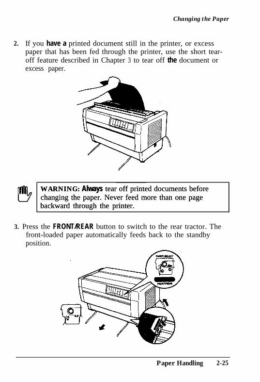
2. If you have a printed document still in the printer, or excesspaper that has been fed through the printer, use the short tear-off feature described in Chapter 3 to tear off the document orexcess paper.
WARNING: Always tear off printed documents beforeWARNING: Always tear off printed documents beforechanging the paper. Never feed more than one pagechanging the paper. Never feed more than one pagebackward through the printer.backward through the printer.
3. Press the FRONT/REAR button to switch to the rear tractor. Thefront-loaded paper automatically feeds back to the standbyposition.
Paper Handling 2-25
Changing the Paper
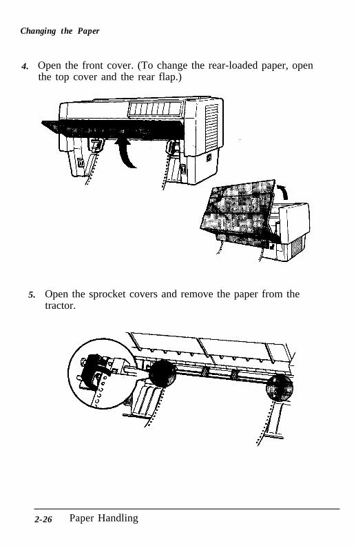
4.. Open the front cover. (To change the rear-loaded paper, openthe top cover and the rear flap.)
5.. Open the sprocket covers and remove the paper from thetractor.
2-26 Paper Handling
Changing the Paper
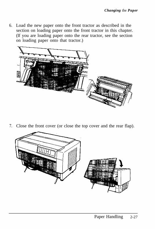
6.. Load the new paper onto the front tractor as described in thesection on loading paper onto the front tractor in this chapter.(If you are loading paper onto the rear tractor, see the sectionon loading paper onto that tractor.)
7. Close the front cover (or close the top cover and the rear flap).
Paper Handling 2-27
Changing the Paper
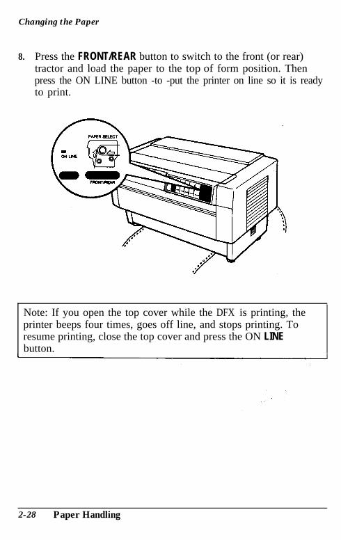
8. Press the FRONT/REAR button to switch to the front (or rear)tractor and load the paper to the top of form position. Thenpress the ON LINE button -to -put the printer on line so it is readyto print.
Note: If you open the top cover while the DFX is printing, theprinter beeps four times, goes off line, and stops printing. Toresume printing, close the top cover and press the ON LINEbutton.
2-28 Paper Handling

Printing on Special Paper
The DFX-8000 can print on various types of paper, including multi-part forms and labels. It can also handle a variety of paperthicknesses, from thin paper to six-part forms. The printerautomatically adjusts to the thickness and width of your paper.
When you print on multi-part forms and labels, the positioning ofyour text on the page can be critical. For more. information onaligning your text, see the sections on adjusting the top. of form andprinting positions in Chapter 3. You should also check both yourprinter and your software page length settings before you loadlabels or forms. See the section on page length in Chapter 3.
If you are using labels or preprinted or multi-part forms, you maywant to use the optional pull tractor. See Chapter 5.
WARNING: When printing on multi-part forms or labels,make sure that your printing stays within the printablearea of the paper to prevent damage to the print head.For more information on the printable area, see page 8-6.
Copy mode
If the printing on the last pages of your multi-part forms is toofaint, you can use the DFX-8000’s copy mode to print clearer,darker characters on each page. In copy mode, which is availableonly for draft, not NLQ, the DFX-8000 prints at half the normalspeed.
To select or cancel copy mode, press the FORM FEED/COPY buttonwhen the ON LINE light is on. When you select copy mode, theprinter beeps twice; when you cancel copy mode, the printer beepsonce.
Paper Handling 2-29
Printing on Special Paper
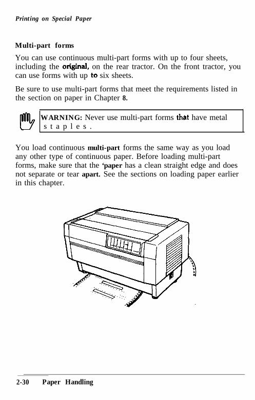
Multi-part forms
You can use continuous multi-part forms with up to four sheets,including the or@inal, on the rear tractor. On the front tractor, youcan use forms with up ito six sheets.
Be sure to use multi-part forms that meet the requirements listed inthe section on paper in Chapter 8.
WARNING: Never use multi-part forms thst have metals t a p l e s .
You load continuous multi-part forms the same way as you loadany other type of continuous paper. Before loading multi-partforms, make sure that the ‘paper has a clean straight edge and doesnot separate or tear apart. See the sections on loading paper earlierin this chapter.
2-30 Paper Handling
Printing on Special Paper
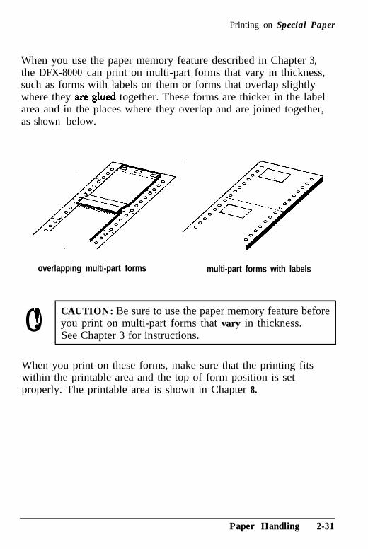
When you use the paper memory feature described in Chapter 3,the DFX-8000 can print on multi-part forms that vary in thickness,such as forms with labels on them or forms that overlap slightlywhere they are.glued together. These forms are thicker in the labelarea and in the places where they overlap and are joined together,as shown below.
overlapping multi-part forms multi-part forms with labels
0t CAUTION: Be sure to use the paper memory feature beforel you print on multi-part forms that vary in thickness.
See Chapter 3 for instructions.
When you print on these forms, make sure that the printing fitswithin the printable area and the top of form position is setproperly. The printable area is shown in Chapter 8.
Paper Handling 2-31
Printing on Special Paper
Labels
When using labels, always choose the type mounted on a continuousbacking sheet with sprocket holes for use with a tractor. Labelsshould be used in t h e front tractor only. You load labels the sameway that you load continuous paper. See the section on loadingpaper onto the front tractor earlier in this chapter.
WARNING: Never use the TEAR OFF, FRONT/REAR, orreverse-feeding (bottom) MICRO FEED button when labels are
through the printer because they can easily come off the
Although you must never feed labels backward through the printer,you can still use the DFX-8000’s automatic paper handling featuresif you follow these precautions:
Instead of’ using the TEAR OFF button to remove printed labels,take the printer off line and press the FORM FEED or LINE FEEDbutton until the last printed label is at the point where you cantear it off easily.
Before using the FRONT/REAR button to &itch tractors ,or changepaper, remove the entire supply of labels. To remove labels,always tear off the fresh supply at a perforation below thetractor and then press the FORM FEED or LtNE FEED: button toeject the remaining labels.
When you adjust the top of form or printing position, use onlythe forward-feeding (top) MICRO FEED button.
2-32 Paper Handling
Printing on Special Paper
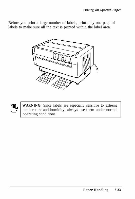
Before you print a large number of labels, print only one page oflabels to make sure all the text is printed within the label area.
WARNING: Since labels are especially sensitive to extremetemperature and humidity, always use them under normaloperating conditions.
Paper Handling 2-33
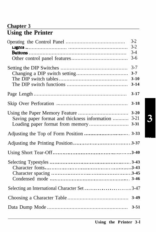
Chapter 3Using the PrinterOperating the Control Panel ....................................... 3-2
...........................But&3
....................................... 3-2................................................................ 3-4
Other control panel features..................................... 3-6
Setting the DIP Switches ............................................ 3-7Changing a DIP switch setting.................................. 3-7The DIP switch tables ............................................. 3-10The DIP switch functions ........................................ 3-14
Page Length ............................................................. 3-17
Skip Over Perforation . . ............................................. 3-18
Using the Paper Memory Feature ................................. 3-20Saving paper format and thickness information ........... 3-21Loading paper format from memory .......................... 3-31
Adjusting the Top of Form Position . . . . . . . . . . . . . . . . . . . . . . . . . . . . . 3-33
Adjusting the Printing Position . . . . . . . . . . . . . . . . . . . . . . . . . . . . . . . . . . . .3-37
Using Short Tear-Off . . . . . . . . . . . . . . . . . . . . . . . . . . . . . . . . . . . . . . . . . . . . . . . . .3-40
Selecting Typestyles . . . . . . . . . . . . . . . . . . . . . . . . . . . . . . . . . . . . . . . . . . . . . . . . . . . 3-43Character fonts . . . . . . . . . . . . . . . . . . . . . . . . . . . . . . . . . . . . . . . . . . . . . . . . . . . . . .3-43Character spacing . . . . . . . . . . . . . . . . . . . . . . . . . . . . . . . . . . . . . . . . . . . . . . . . . .3-45Condensed mode . . . . . . . . . . . . . . . . . . . . . . . . . . . . . . . . . . . . . . . . . . . . . . . . . . . 3-46
Selecting an International Character Set . . . . . . . . . . . . . . . . . . . . . . . . 3-47
Choosing a Character Table ........................................ 3-49
Data Dump Mode ..................................................... 3-51
Using the Printer 3-l
Operating the Control Panel
The DFX-8000’s control panel gives you access to several powerfulfeatures. The control panel buttons let you control paper loading,primer settings, and more. The control panel indicator lights giveyou status information such as which mode the printer is in, whichtractor is loaded with paper, and which tractor is ready to print.The following sections describe the functions of the control panel’slights and buttons.
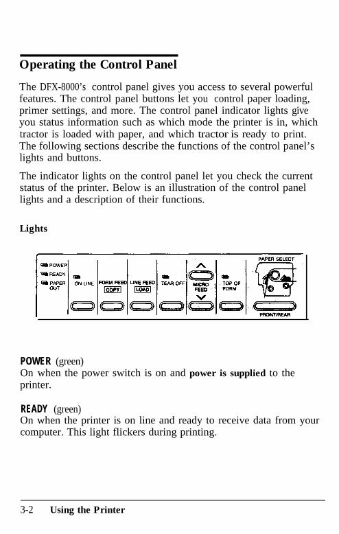
The indicator lights on the control panel let you check the currentstatus of the printer. Below is an illustration of the control panellights and a description of their functions.
Lights
POWER (green)On when the power switch is on and power is supplied to theprinter.
READY (green)On when the printer is on line and ready to receive data from yourcomputer. This light flickers during printing.
3-2 Using the Printer
Operating the Control Panel
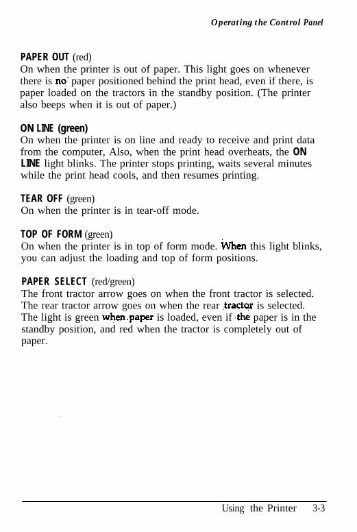
PAPER OUT (red)On when the printer is out of paper. This light goes on wheneverthere is no: paper positioned behind the print head, even if there, ispaper loaded on the tractors in the standby position. (The printeralso beeps when it is out of paper.)
ON LINE (green)On when the printer is on line and ready to receive and print datafrom the computer, Also, when the print head overheats, the ONLINE light blinks. The printer stops printing, waits several minuteswhile the print head cools, and then resumes printing.
TEAR OFF (green)On when the printer is in tear-off mode.
TOP OF FORM (green)On when the printer is in top of form mode. tvhen this light blinks,you can adjust the loading and top of form positions.
PAPER SELECT (red/green)The front tractor arrow goes on when the front tractor is selected.The rear tractor arrow goes on when the rear .tractor is selected.The light is green when&paper is loaded, even if ,the paper is in thestandby position, and red when the tractor is completely out ofpaper.
Using the Printer 3-3
Operating the Control Panel
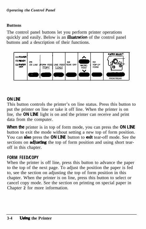
Buttons
The control panel buttons let you perform printer operationsquickly and easily. Below is an Uustration of the control panelbuttons and a description of their functions.
OPOWER
c1- a c3ON LINE M FEED LINE FEED TEAR OFF
FEED FORM
- - - v, -. FRONT/REAR
ON LINEThis button controls the printer’s on line status. Press this button toput the printer on line or take it off line. When the printer is online, the ON LINE light is on and the printer can receive and printdata from the computer.
When the printer is in top of form mode, you can press the ON LINEbutton to exit the mode without setting a new top of form position.You can Also press the ON LINE button to &it tear-off mode. See thesections on adjtisting the top of form position and using short tear-off in this chapter.
FORM FEED/COPYWhen the printer is off line, press this button to advance the paperto the top of the next page. To adjust the position the paper is fedto, see the section on adjusting the top of form position in thischapter. When the printer is on line, press this button to select orcancel copy mode. See the section on printing on special paper inChapter 2 for more information.
3-4 Utdng the Printer
Operating the Control Panel
LINE FEED/LOADWhen the printer is off line, you use this button to load paper or toadvance the paper after you load it. To advance the paper one line,press this button once. To advance the paper continuously, holddown the button.
TEAR OFFThe TEAR OFF button feeds the paper to the printer’s tear-off edge soyou can tear off your document without losing the paper. normallylost between printing jobs. To use this feature, take the printer offline after your document finishes printing and press the TEAR OFFbutton. The printer feeds the paper to the printer’s tear-off edge.After you tear off the document, press the TEAR OFF or ON LINEbutton to feed the paper back to the top of form position.
If the perforation of your paper does not align exactly with the printer’stear-off edge, you can use the MICRO FEED buttons to adjust the tear-offposition. See the section on using short tear-off in this chapter.
WARNING Never use the TEAR OFF button with labels.Press the FORM FEED or LINE FEED button instead to feedthe printed labels to a point where you can tear them off.
MICRO FEEDWhen the printer is off line, the two MICRO FEED buttons advance orreverse the loaded paper in 1/216th-inch increments. You can usethese buttons to adjust the paper memory, top of form, loading,printing, and tear-off positions. For more information, see thesections on using the paper memory and short tear-off features andadjusting the top of form and printing positions in this chapter.
TOP OF FORMWhen the printer is off line, press this button to enter or exit top ofform mode. You can also use this button to enter paper memorysettings. For more information, see the sections on adjusting the topof form position and using the paper memory feature in thischapter.
Using the Printer 3-5
Operating the Control Panel
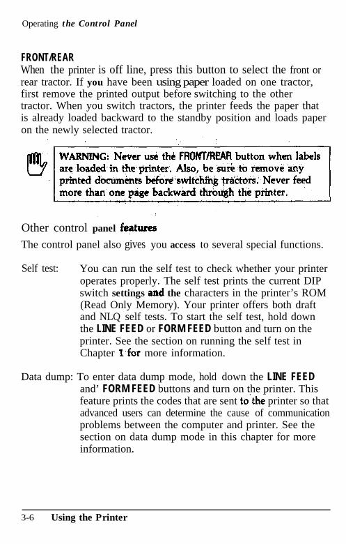
FRONT/REARWhen the printer is off line, press this button to select the front orrear tractor. If you have been using paper loaded on one tractor,first remove the printed output before switching to the othertractor. When you switch tractors, the printer feeds the paper thatis already loaded backward to the standby position and loads paperon the newly selected tractor.
Other control panel f@ures
The control panel also gives you access to several special functions.
Self test: You can run the self test to check whether your printeroperates properly. The self test prints the current DIPswitch settings and the characters in the printer’s ROM(Read Only Memory). Your printer offers both draftand NLQ self tests. To start the self test, hold downthe LINE FEED or FORM FEED button and turn on theprinter. See the section on running the self test inChapter l’for more information.
Data dump: To enter data dump mode, hold down the LINE FEEDand’ FORM FEED buttons and turn on the printer. Thisfeature prints the codes that are sent to’the printer so thatadvanced users can determine the cause of communicationproblems between the computer and printer. See thesection on data dump mode in this chapter for moreinformation.
3-6 Using the Printer
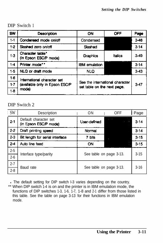
Setting the DIP Switches
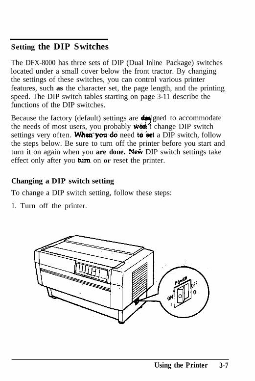
The DFX-8000 has three sets of DIP (Dual Inline Package) switcheslocated under a small cover below the front tractor. By changingthe settings of these switches, you can control various printerfeatures, such as the character set, the page length, and the printingspeed. The DIP switch tables starting on page 3-11 describe thefunctions of the DIP switches.
Because the factory (default) settings are9
igned to accommodatethe needs of most users, you probably MM t change DIP switchsettings very often. WAenyoudo need to &t a DIP switch, followthe steps below. Be sure to turn off the printer before you start andturn it on again when you are done. Neti DIP switch settings takeeffect only after you tum on or reset the printer.
Changing a DIP switch setting
To change a DIP switch setting, follow these steps:
1. Turn off the printer.
Using the Printer 3-7
Setting the DIP Switches
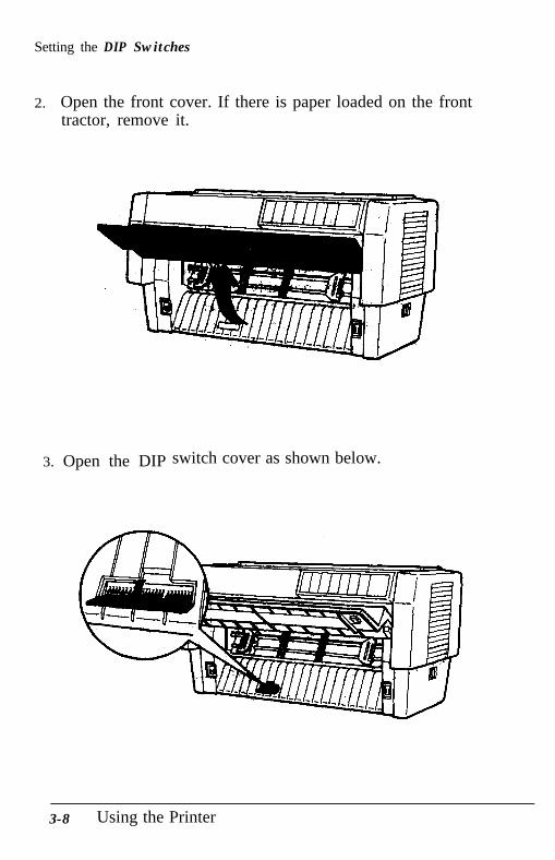
2.. Open the front cover. If there is paper loaded on the fronttractor, remove it.
3. Open the DIP switch cover as shown below.
3-8 Using the Printer
Setting the DIP Switches
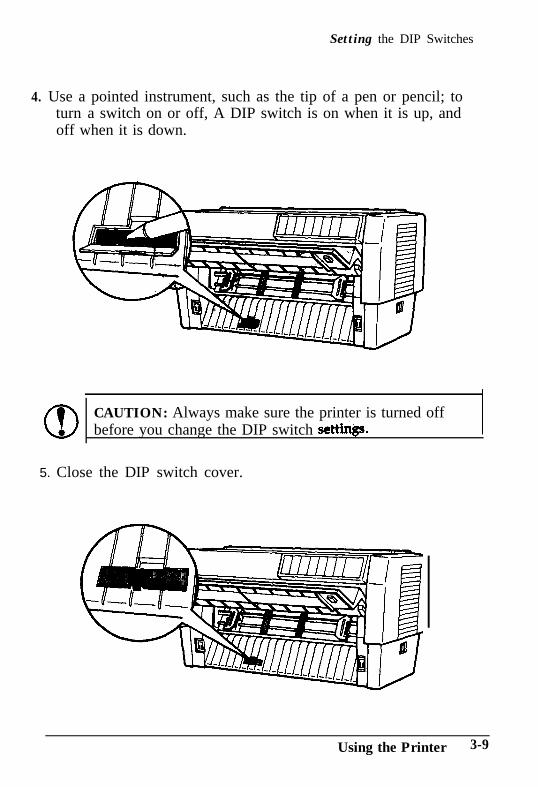
4. Use a pointed instrument, such as the tip of a pen or pencil; toturn a switch on or off, A DIP switch is on when it is up, andoff when it is down.
CAUTION: Always make sure the printer is turned offbefore you change the DIP switch setti~&~.
5. Close the DIP switch cover.
Using the Printer 3-9
Setting the DIP Switches
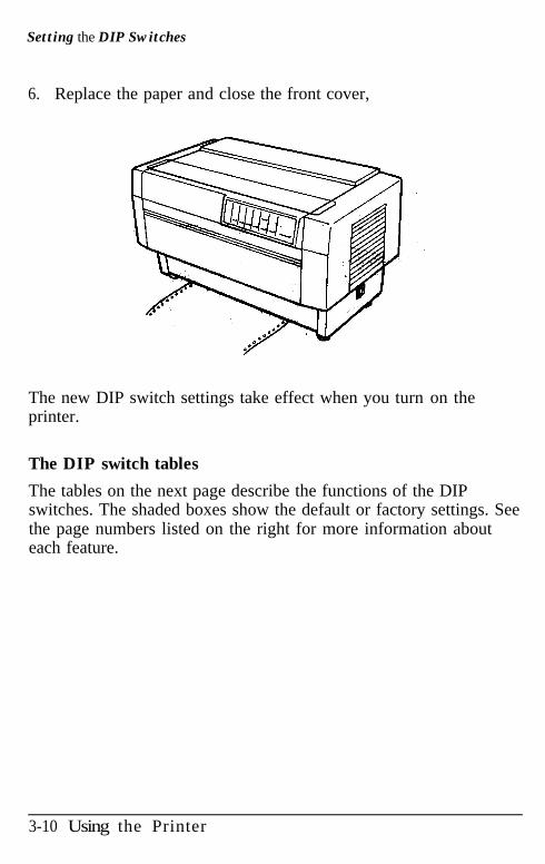
6.. Replace the paper and close the front cover,
The new DIP switch settings take effect when you turn on theprinter.
The DIP switch tables
The tables on the next page describe the functions of the DIPswitches. The shaded boxes show the default or factory settings. Seethe page numbers listed on the right for more information abouteach feature.
3-10 Using the Printer
Setting the DIP Switches
DIP Switch 1
DIP Switch 2
1 SW 1 Description I ON I OFF 1 Page
Default character set
2-5- Interface type/parity Seee table on
2-6page 3-13. 3-15
2-7- Baud rate Seee table on
2-8page 3-13. 3-16
l The default setting for DIP switch l-3 varies depending on the country.** When DIP switch 1-4 is on and the printer is in IBM emulation mode, the
functions of DIP switches 1-3, 1-6, 1-7, 1-8 and 2-1 differ from those listed inthis table. See the table on page 3-13 for their functions in IBM emulationmode.
Using the Printer 3-11
Setting the DIP Switches
DIP Switch 3
3-2 Page length 12 inches 11 inches I 3-17 I l-inch skip over perforation
Paper memory
Ovf&laooinh m&i-oat-t forms
Multi-part forms with labels
Skip over binding
Handshaking protocol
ON
Memory 2
Valid
Valid
ON
X-on/X-&f
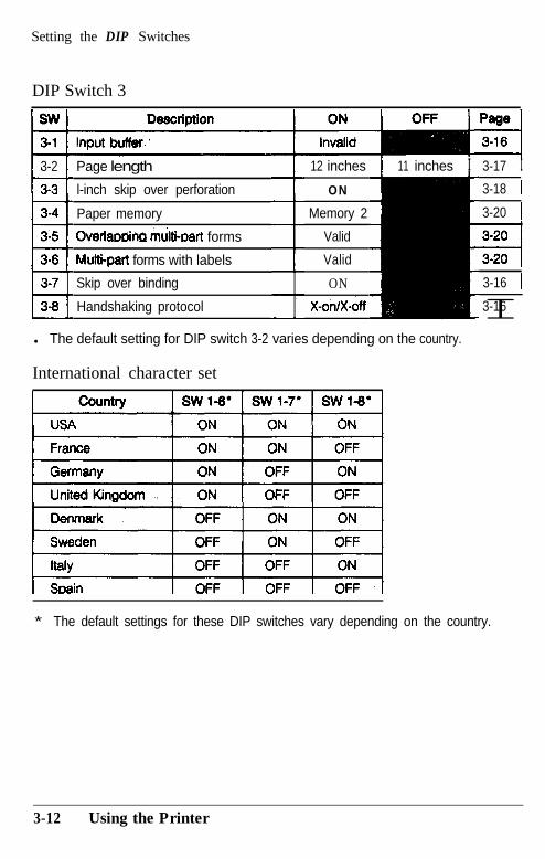
l The default setting for DIP switch 3-2 varies depending on the country.
International character set
3-18 I
3-20 1
3-16 1
I3-16
* The default settings for these DIP switches vary depending on the country.
3-12 Using the Printer
Setting the DIP Switches
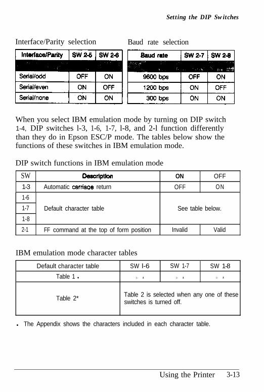
Interface/Parity selection Baud rate selection
When you select IBM emulation mode by turning on DIP switch1-4, DIP switches l-3, 1-6, 1-7, l-8, and 2-l function differentlythan they do in Epson ESC/P mode. The tables below show thefunctions of these switches in IBM emulation mode.
DIP switch functions in IBM emulation mode
SW Q8scriptiin ON OFF
1-3 Automatic cafriaae return OFF ON
1-6
1-7
1-8
2-1
Default character table See table below.
FF command at the top of form position Invalid Valid
IBM emulation mode character tables
Default character table SW l-6 SW 1-7 SW 1-8
Table 1 l O N O N O N
Table 2* Table 2 is selected when any one of theseswitches is turned off.
l The Appendix shows the characters included in each character table.
Using the Printer 3-13
Setting the DIP Switches
The DIP switch functions
This section describes the different features you can control with theprinter’s DIP switches.
Slashed zero
When DIP switch l-2 is on, the printer prints slashed zeros(0).When the DIP switch is off, the printer prints open zeros (0). Thisfeature is useful for clearly distinguishing between uppercase 0 andzero when printing documents such as program lists.
Printer mode
When DIP switch l-4 is on, the printer operates in IBM emulationmode. When the DIP switch is off, the printer operates in EpsonESC/P mode. The functions of DIP switches 1-3, 1-6, 1-7, 1-8, and2-1 in IBM emulation mode differ from their functions in EpsonESC/P mode. The tables on the previous page describe the specialfunctions of these DIP switches in IBM emulation mode.
Default character set
When DIP switch 2-l is on, the user-defined character set is thedefault. User-defined characters are maintained in the printer’smemory even when the power is turned off, so you can select theuser-defined character set simply by turning on this DIP switch.However, when the switch is on, you cannot define new user-defined characters. The setting of this DIP switch takes effect only ifDIP switch l-4 is set for Epson ESC/P mode. See Chapter 4 formore information on user-defined characters.
Draft printing speed
When DIP switch 2-2 is off, high-speed draft mode is selected.When the switch is on, normal draft mode is selected. This switchonly affects the printer if DIP switch 1-5 is set for draft mode(turned off) or if draft mode is selected through your software. Inhigh-speed draft mode, the DFX-8000 can print up to 1066characters per second at 10 cpi (characters per inch). In normal
3-14 Using the Printer
Setting the DIP Switches
draft mode, the DFX-8000 prints up to 800 characters per second at10 cpi. Normal draft mode produces characters that are more fullyformed than characters produced in high-speed draft mode.
Note: High-speed draft mode is available only for 10 cpi printing.Also, underlining and double-wide are the only print enhancementsthat work in high-speed draft mode. If you use a feature such asemphask$:double-strike, or italics in highqmd draft mode, theprinter temporarily slows to the normal draft speed until the featureis turned off. This allows you to use any print enhancement withoutcancelling high-speed draft mode.
Bit length for serial interface
When DIP switch 2-3 is on, the bit length for the serial interface isset to 7 bits. When the DIP switch is off, the bit length is set to 8 bits.
Auto line feed
When DIP, switch 2-4 is on, the printer adds a line feed (LF)command to every carriage return (CR) code sent by the applicationprogram. When the switch is off, line feeds occur only when thesoftware sends line feed commands to the printer. Since mostcomputers and application programs automatically add line feeds tocarriage returns, you should use this feature only if your text isprinting all on one line.
Interface parity
If your computer is set up for serial communication, you need tochange DIP switches 2-5 and 2-6 so that your printer and computercan communicate properly. These DIP switches control the interfacetype and parity. (You may also need to select a different baud rateas described in the next section.)
The table on page 3-13 shows the DIP switch settings for a parallelinterface and a serial interface with odd, even, or no parity. If you
Using the Printer 3-15
Setting the DIP Switches
don’t know what type of interface your computer requires, checkyour computer manual. A&o check your computer manual to makesure your computer and printer have the same parity settings.
Baud rate
If your computer is set up for serial communication, you may needto set the baud rate in addition to selecting serial interface andsetting the parity. The baud rate is the rate at which the printerreceives data from the computer.
DIP switches 2-7 and 2-8 control the baud rate. The table on page3-13 shows the DIP switch settings for the printer's four baud ratesettings. Check your computer or application program manual forthe correct baud rate setting. Your computer and printer shouldalways be set to the same baud rate.
Input buffer
The printer’s input buffer provides additional memory to free up thecomputer while you print large amounts of text or graphics. Theinput buffer is enabled when DIP switch 3-1 is off. To disable thebuffer, turn on DIP switch 3-1.
Skip over binding
When DIP switch 3-7 is on, the print head avoids the binding areaalong the right and left edges of multi-part forms during paperfeeding. Using this feature helps avoid paper jams when you usemulti-part forms.
Hand- protocol
If your computer is set up for serial communication, you may needto select the handshaking protocol.
When DIP switch 3-8 is on, the printer uses X-on/X-offhandshaking protocol. When the switch is off, the printer uses DTR(Data Terminal Ready) handshaking protocol.
3-16 Using the Printer
Page Length
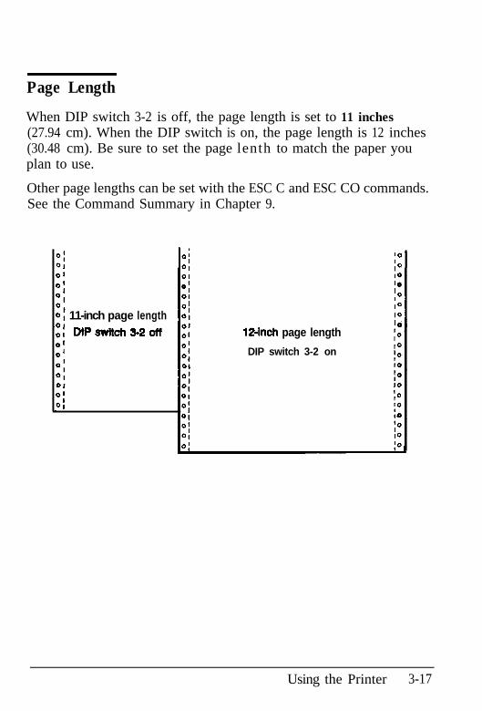
When DIP switch 3-2 is off, the page length is set to 11 inches(27.94 cm). When the DIP switch is on, the page length is 12 inches(30.48 cm). Be sure to set the page lenth to match the paper youplan to use.
Other page lengths can be set with the ESC C and ESC CO commands.See the Command Summary in Chapter 9.
11-inch page lengthDPswitch?)-2off 1Pinch page length
DIP switch 3-2 on
Using the Printer 3-17
Skip Over Perforation
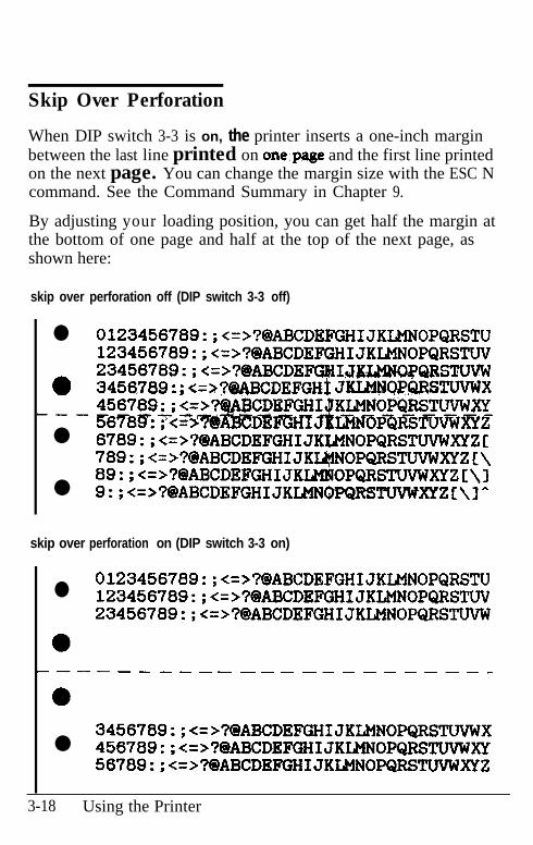
When DIP switch 3-3 is on, the printer inserts a one-inch marginbetween the last line printed on one;page and the first line printedon the next page. You can change the margin size with the ESC Ncommand. See the Command Summary in Chapter 9.
By adjusting your loading position, you can get half the margin atthe bottom of one page and half at the top of the next page, asshown here:
skip over perforation off (DIP switch 3-3 off)
l 0123456789:;<=>?@ABCDEFGHIJKLMNOPQRSTU123456789:;<=>?@ABCDEFGHIJKLMNOPQRSTW
.23456789:;c=>?@ABCDEFGBIJKI#lNQPQRSTWW3456.789 : ; <=>?@ABCDEFGHI JKDMHQPQRSTWWX
i-- 456789:;<=>? DEFGHI$KLMNOPGRSTWWXY?!c?56789’: F<z=% D%md'$mPmmm=z
l 6789:;<=>?QABCDEFGHIJK&MNOPQRSTWWXYZC789:;<=>?@ABCDEFGHIJKL@NOPQRSTWWXYZ~\89:;<=>?@ABCDEFGHIJKLMMOPQRSTWWXYZC\l
l Q:;<=>?@ABCDEFGHIJKLMNQPQRSTWbMYZ~\l-
skip over perforation on (DIP switch 3-3 on)
l 0123456789:;<=>?@ABCDEFGHIJKLMNOPQRSTU123456789:;<=>?@?ABCDEFGHIJKLMNOPQRSTW23456789:;<=>?@ABCDEFGHIJKLMNOPQRSTWW
----------_~----------_0
3456789:;<=>?QABCDEFGHIJKL,MNOPQRSTUVWXl 456789:;<=>?@ABCDEFGHIJKLMNOPQR!ZTW!dXY
56789:;<=>?@ABCDEFGHIJKLMNOPQRSTWWXYZ
3-18 Using the Printer
Skip Over Perforation
insert their own topover perforation
feature only if your program does not provide them.
Using the Printer 3-19
Using the Paper Memory Feature
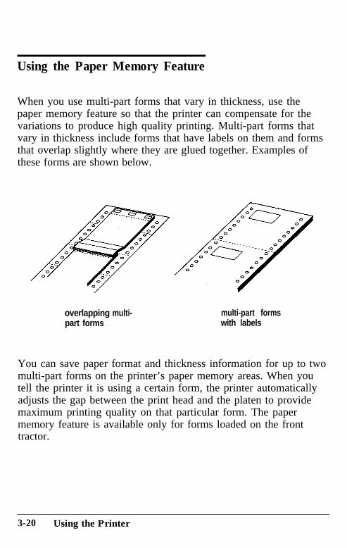
When you use multi-part forms that vary in thickness, use thepaper memory feature so that the printer can compensate for thevariations to produce high quality printing. Multi-part forms thatvary in thickness include forms that have labels on them and formsthat overlap slightly where they are glued together. Examples ofthese forms are shown below.
overlapping multi- multi-part formspart forms with labels
You can save paper format and thickness information for up to twomulti-part forms on the printer’s paper memory areas. When youtell the printer it is using a certain form, the printer automaticallyadjusts the gap between the print head and the platen to providemaximum printing quality on that particular form. The papermemory feature is available only for forms loaded on the fronttractor.
3-20 Using the Printer
Using the Paper Memory Feature
WARNING: When you use multi-part forms that vary inthickness, do not press the TEAR OFF, FRONT/REAR, orreverse-feeding (bottom) MICRO FEED button or a paperjam may result. To remove these forms, tear off the freshsupply at a perforation below the front tractor, take theprinter off line, and press the FORM FEED or LINE FEEDbutton to eject the remaining forms.
Note: To use the paper memory feature, you need to reset someDIP switches. See the section on changing a DIP switch setting inthis chapter for instructions on how to set a DIP switch.
Saving paper format and thickness information
The following sections describe how to save paper format andthickness information for different types of multi-part forms.
Saving information for overlapping multi-part forms
To save paper format and thickness information for multi-partforms that overlap slightly where they are joined together, followthe steps below.
1. Turn off the printer.
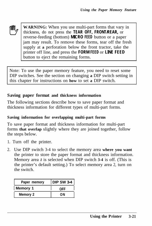
2.. Use DIP switch 3-4 to select the memory area where you wantthe printer to store the paper format and thickness information.Memory area 1 is selected when DIP switch 3-4 is off. (This isthe printer’s default setting.) To select memory area 2, turn onthe switch.
Paper memory 1 DIP SW 3-4
1 Memory 1 i OFF 1Memory 2 ON
Using the Printer 3-21
Using the Paper Memory Feature
Note: Be sure to remember or write down the memory area youuse for each form.
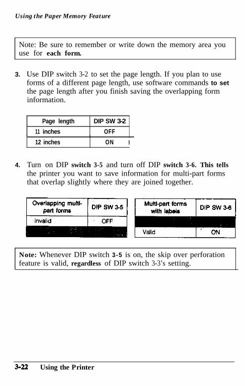
3.. Use DIP switch 3-2 to set the page length. If you plan to useforms of a different page length, use software commands to setthe page length after you finish saving the overlapping forminformation.
Page length DIP SW 3-2
11 inches OFF
12 inchesI
ON I
4. Turn on DIP switch 3-5 and turn off DIP switch 3-6. This tellsthe printer you want to save information for multi-part formsthat overlap slightly where they are joined together.
Note: Whenever DIP switch 3-5 is on, the skip over perforationfeature is valid, regardless of DIP switch 3-3’s setting.
3-22 Using the Printer
Using the Paper Memory Feature
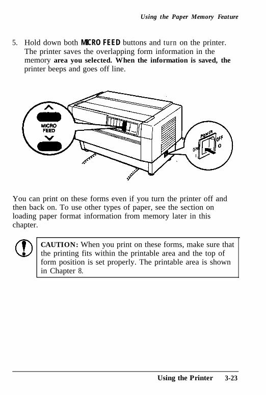
5.. Hold down both MICRO FEED buttons and turn on the printer.The printer saves the overlapping form information in thememory area you selected. When the information is saved, theprinter beeps and goes off line.
You can print on these forms even if you turn the printer off andthen back on. To use other types of paper, see the section onloading paper format information from memory later in thischapter.
CAUTION: When you print on these forms, make sure thatthe printing fits within the printable area and the top ofform position is set properly. The printable area is shownin Chapter 8.
Using the Printer 3-23
Using the Paper Memory Feature
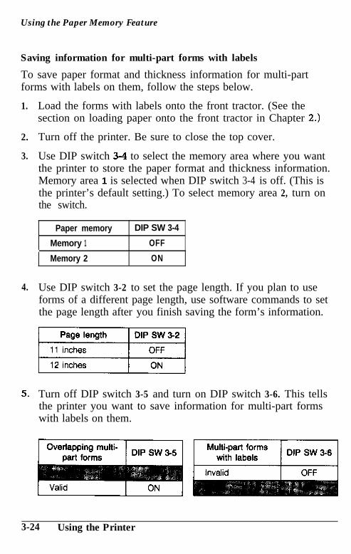
Saving information for multi-part forms with labels
To save paper format and thickness information for multi-partforms with labels on them, follow the steps below.
1.
2.
3.
4.
5.
Load the forms with labels onto the front tractor. (See thesection on loading paper onto the front tractor in Chapter 2.)
Turn off the printer. Be sure to close the top cover.
Use DIP switch 3-4 to select the memory area where you wantthe printer to store the paper format and thickness information.Memory area 1 is selected when DIP switch 3-4 is off. (This isthe printer’s default setting.) To select memory area 2, turn onthe switch.
Paper memory DIP SW 3-4
Memory 1 OFF
Memory 2 ON
Use DIP switch 3-2 to set the page length. If you plan to useforms of a different page length, use software commands to setthe page length after you finish saving the form’s information.
Turn off DIP switch 3-5 and turn on DIP switch 3-6. This tellsthe printer you want to save information for multi-part formswith labels on them.
3-24 Using the Printer
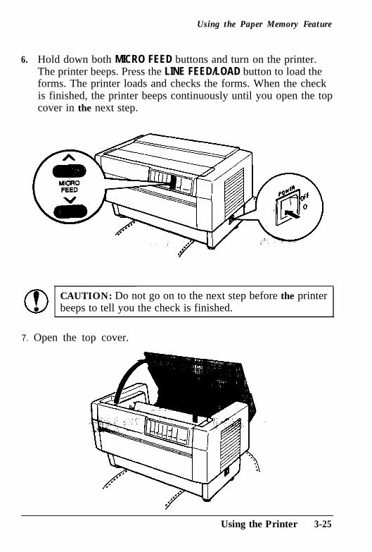
Using the Paper Memory Feature
6. Hold down both MICRO FEED buttons and turn on the printer.The printer beeps. Press the LINE FEED/LOAD button to load theforms. The printer loads and checks the forms. When the checkis finished, the printer beeps continuously until you open the topcover in the next step.
CAUTION: Do not go on to the next step before the printerbeeps to tell you the check is finished.
7. Open the top cover.
Using the Printer 3-25
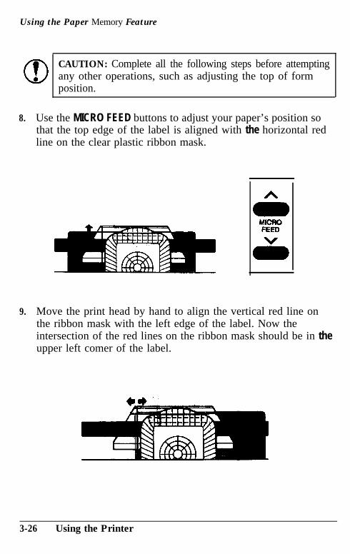
Using the Paper Memory Feature
CAUTION: Complete all the following steps before attemptingany other operations, such as adjusting the top of formposition.
8. Use the MICRO FEED buttons to adjust your paper’s position sothat the top edge of the label is aligned with the horizontal redline on the clear plastic ribbon mask.
9. Move the print head by hand to align the vertical red line onthe ribbon mask with the left edge of the label. Now theintersection of the red lines on the ribbon mask should be in theupper left comer of the label.
3-26 Using the Printer
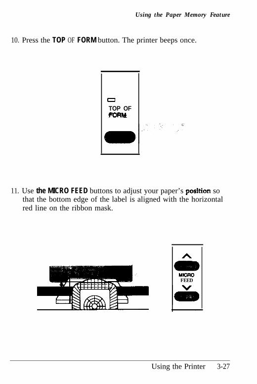
Using the Paper Memory Feature
10. Press the TOP OF FORM button. The printer beeps once.
0
TOP OFVORM
11. Use the MICRO FEED buttons to adjust your paper’s posftion sothat the bottom edge of the label is aligned with the horizontalred line on the ribbon mask.
h
FEED
Using the Printer 3-27
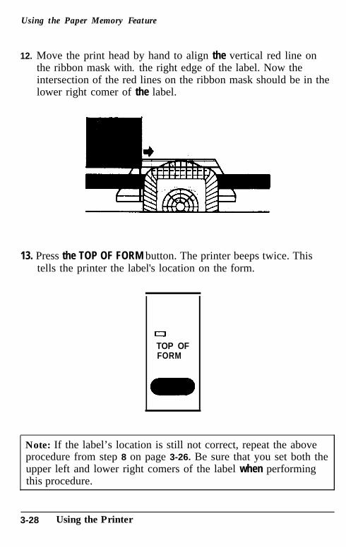
Using the Paper Memory Feature
12. Move the print head by hand to align the vertical red line onthe ribbon mask with. the right edge of the label. Now theintersection of the red lines on the ribbon mask should be in thelower right comer of the label.
13. Press the TOP OF FORM button. The printer beeps twice. Thistells the printer the label's location on the form.
aTOP OFFORM
Note: If the label’s location is still not correct, repeat the aboveprocedure from step 8 on page 3-26. Be sure that you set both theupper left and lower right comers of the label when performingthis procedure.
3-28 Using the Printer
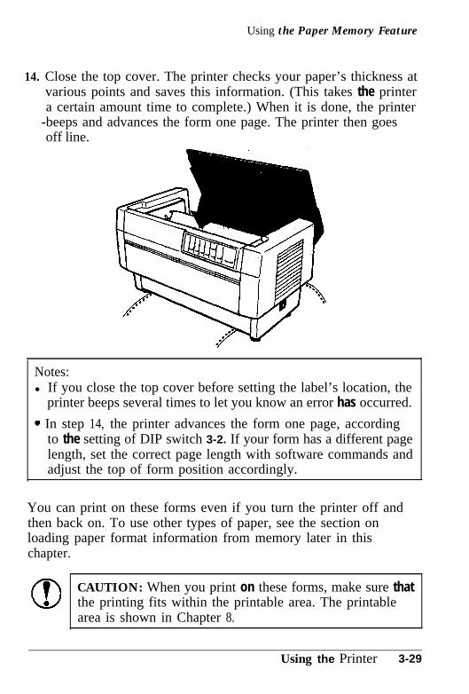
Using the Paper Memory Feature
14. Close the top cover. The printer checks your paper’s thickness atvarious points and saves this information. (This takes the printera certain amount time to complete.) When it is done, the printer
-beeps and advances the form one page. The printer then goesoff line.
Notes:l If you close the top cover before setting the label’s location, the
printer beeps several times to let you know an error has occurred.
* In step 14, the printer advances the form one page, accordingto the setting of DIP switch 3-2. If your form has a different pagelength, set the correct page length with software commands andadjust the top of form position accordingly.
You can print on these forms even if you turn the printer off andthen back on. To use other types of paper, see the section onloading paper format information from memory later in thischapter.
CAUTION: When you print on these forms, make sure thatthe printing fits within the printable area. The printablearea is shown in Chapter 8.
Using the Printer 3-29
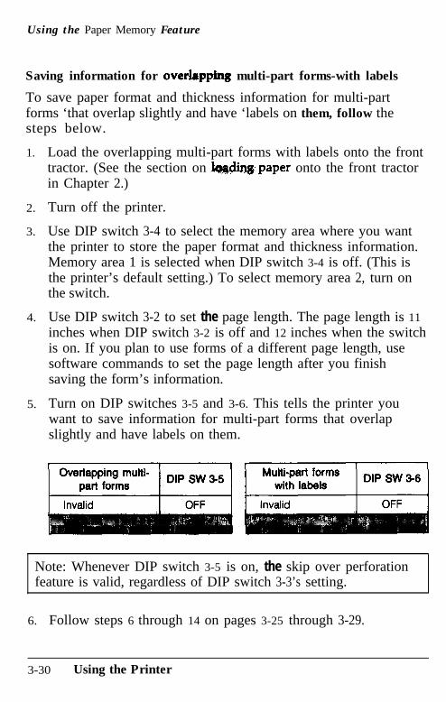
Using the Paper Memory Feature
Saving information for overlappb multi-part forms-with labels
To save paper format and thickness information for multi-partforms ‘that overlap slightly and have ‘labels on them, follow thesteps below.
1.
2.
3.
4.
5.
Load the overlapping multi-part forms with labels onto the fronttractor. (See the section on lqqdingpaper onto the front tractorin Chapter 2.)
Turn off the printer.
Use DIP switch 3-4 to select the memory area where you wantthe printer to store the paper format and thickness information.Memory area 1 is selected when DIP switch 3-4 is off. (This isthe printer’s default setting.) To select memory area 2, turn onthe switch.
Use DIP switch 3-2 to set the page length. The page length is 11inches when DIP switch 3-2 is off and 12 inches when the switchis on. If you plan to use forms of a different page length, usesoftware commands to set the page length after you finishsaving the form’s information.
Turn on DIP switches 3-5 and 3-6. This tells the printer youwant to save information for multi-part forms that overlapslightly and have labels on them.
Note: Whenever DIP switch 3-5 is on, the skip over perforationfeature is valid, regardless of DIP switch 3-3’s setting.
6.. Follow steps 6 through 14 on pages 3-25 through 3-29.
3-30 Using the Printer
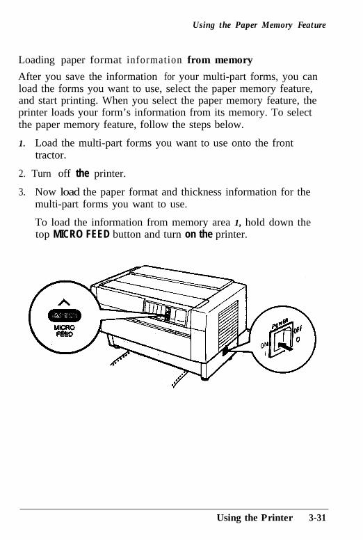
Using the Paper Memory Feature
Loading paper format information from memory
After you save the information for your multi-part forms, you canload the forms you want to use, select the paper memory feature,and start printing. When you select the paper memory feature, theprinter loads your form’s information from its memory. To selectthe paper memory feature, follow the steps below.
1. Load the multi-part forms you want to use onto the fronttractor.
2. Turn off the printer.
3. Now load the paper format and thickness information for themulti-part forms you want to use.
To load the information from memory area 1, hold down thetop MICRO FEED button and turn on the printer.
Using the Printer 3-31
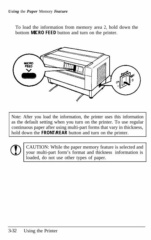
Using the Paper Memory Feature
To load the information from memory area 2, hold down thebottom MICRO FEED button and turn on the printer.
Note: After you load the information, the printer uses this informationas the default setting when you turn on the printer. To use regularcontinuous paper after using multi-part forms that vary in thickness,hold down the FRONT/REAR button and turn on the printer.
CAUTION: While the paper memory feature is selected andyour multi-part form’s format and thickness information isloaded, do not use other types of paper.
3-32 Using the Printer
Adjusting the Top of Form Position
The top of form position is the position the printer feeds the paperto when it loads the paper or performs a form feed. This position isimportant because it determines where the printing begins on eachpage.
If the printing is too high or low on the page, you can reset the topof form position by following the steps below. The printerremembers the new top of form position even after the printer isturned off, reset, or initialized. (The printer remembers separate topof form positions for the front and rear tractors.)
To temporarily change the top of form position, you can adjust theposition when the printer is not in top of form mode or you changethe printing position in the middle of a page as described in the nextsection. The printer remembers the temporary top of form positionuntil the next time you load paper or switch tractors.
You can set the top of form position, from 0.1 inches (2.6 mm) to22 inches (558.8 mm) below the top edge of paper. The factorysetting is the 0.2 inches (5.8 mm) position below the top edge ofpaper.
I!!!!!9WARNING: When labels are loaded in the printer, do notenter top of form mode as described in this section. Toadjust the top of form position when you are using labels,use only the forward-feeding (top) MICRO FEED button.Labels must never be fed backward through the printer.See the section on adjusting the printing position in thischapter.
6
CAUTION: While using the paper memory feature to savethe format information about your multi-part forms, donot try to adjust the top of form position.
Using the Printer 3-33
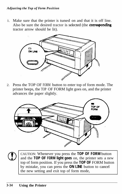
Adjusting the Top of Form Position
1.. Make sure that the printer is tuned on and that it is off line.Also be sure the desired tractor is selected (the correspondillgtractor arrow should be lit).
2.. Press the TOP OF FORM button to enter top of form mode. Theprinter beeps, the TOP OF FORM light goes on, and the printeradvances the paper slightly.
CAUTION: Whenever you press the TOP OF FORM buttonand the TOP OF FORM light goes on, the printer sets a newtop of form position. If you press the TOP OF FORM buttonby mistake, you can press the ON LINE button to cancelthe new setting and exit top of form mode,
3-34 Using the Printer
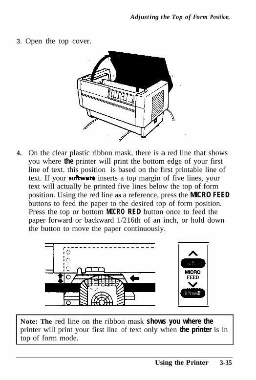
Adjusting the Top of Form Position,
3. Open the top cover.
4. On the clear plastic ribbon mask, there is a red line that showsyou where the printer will print the bottom edge of your firstline of text. this position is based on the first printable line oftext. If your software inserts a top margin of five lines, yourtext will actually be printed five lines below the top of formposition. Using the red line as a reference, press the MICRO FEEDbuttons to feed the paper to the desired top of form position.Press the top or bottom MICRO RED button once to feed thepaper forward or backward 1/216th of an inch, or hold downthe button to move the paper continuously.
FEED
Note: The red line on the ribbon mask shows you where theprinter will print your first line of text only when the printer is intop of form mode.
Using the Printer 3-35
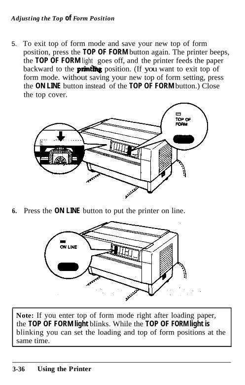
Adjusting the Top of Form Position
5.. To exit top of form mode and save your new top of formposition, press the TOP OF FORM button again. The printer beeps,the TOP OF FORM light goes off, and the printer feeds the paperbackward to the printing position. (If you want to exit top ofform mode. without saving your new top of form setting, pressthe ON LINE button instead of the TOP OF FORM button.) Closethe top cover.
6. Press the ON LINE button to put the printer on line.
Note: If you enter top of form mode right after loading paper,the TOP OF FORM light blinks. While the TOP OF FORM light isblinking you can set the loading and top of form positions at thesame time.
3-36 Using the Printer
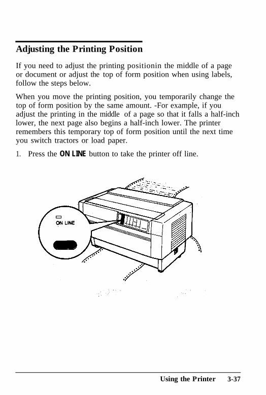
Adjusting the Printing Position
If you need to adjust the printing positionin the middle of a pageor document or adjust the top of form position when using labels,follow the steps below.
When you move the printing position, you temporarily change thetop of form position by the same amount. -For example, if youadjust the printing in the middle of a page so that it falls a half-inchlower, the next page also begins a half-inch lower. The printerremembers this temporary top of form position until the next timeyou switch tractors or load paper.
1. Press the ON LINE button to take the printer off line.
Using the Printer 3-37
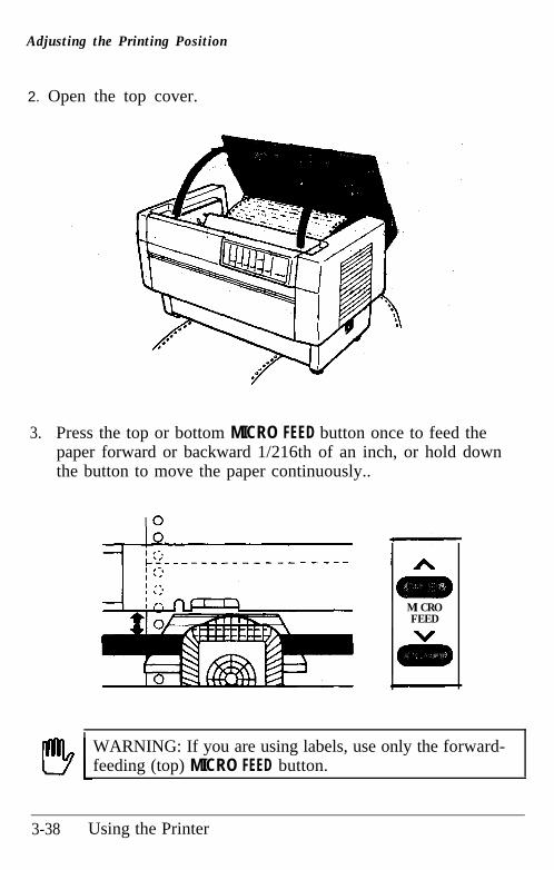
Adjusting the Printing Position
2. Open the top cover.
3.. Press the top or bottom MICRO FEED button once to feed thepaper forward or backward 1/216th of an inch, or hold downthe button to move the paper continuously..
MICROFEED
WARNING: If you are using labels, use only the forward-feeding (top) MICRO FEED button.
3-38 Using the Printer
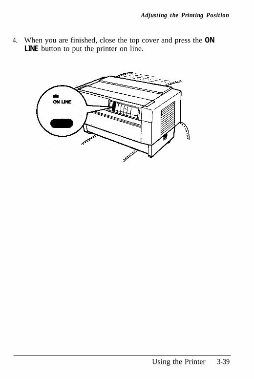
Adjusting the Printing Position
4. When you are finished, close the top cover and press the ONLINE button to put the printer on line.
Using the Printer 3-39
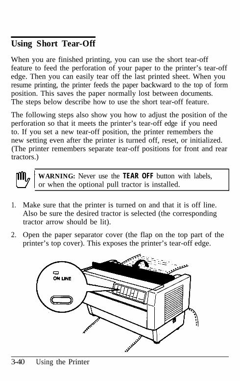
Using Short Tear-Off
When you are finished printing, you can use the short tear-offfeature to feed the perforation of your paper to the printer’s tear-offedge. Then you can easily tear off the last printed sheet. When youresume printing, the printer feeds the paper backward to the top of formposition. This saves the paper normally lost between documents.The steps below describe how to use the short tear-off feature.
The following steps also show you how to adjust the position of theperforation so that it meets the printer’s tear-off edge if you needto. If you set a new tear-off position, the printer remembers thenew setting even after the printer is turned off, reset, or initialized.(The printer remembers separate tear-off positions for front and reartractors.)
!!!!?I WARNING: Never use the TEAR OFF button with labels,or when the optional pull tractor is installed.
1. Make sure that the printer is turned on and that it is off line.Also be sure the desired tractor is selected (the correspondingtractor arrow should be lit).
2.. Open the paper separator cover (the flap on the top part of theprinter’s top cover). This exposes the printer’s tear-off edge.
3-40 Using the Printer
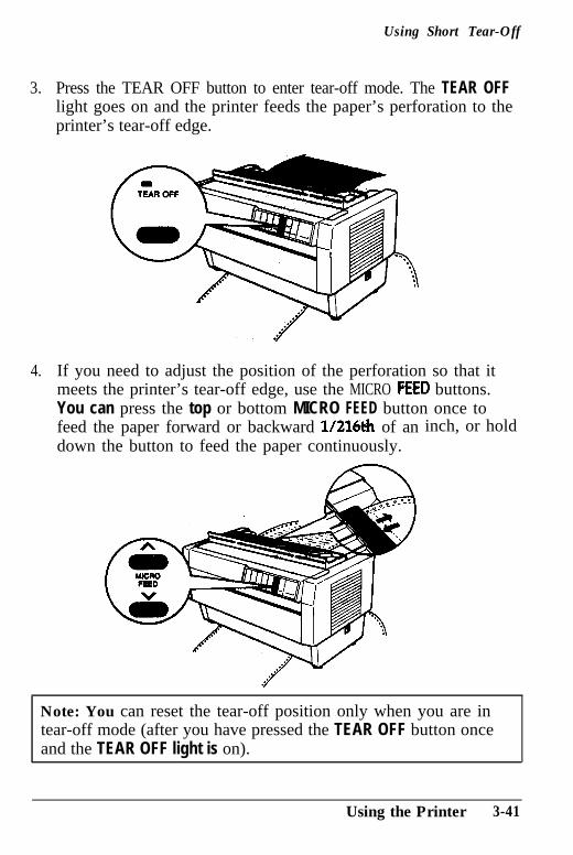
Using Short Tear-Off
3.. Press the TEAR OFF button to enter tear-off mode. The TEAR OFFlight goes on and the printer feeds the paper’s perforation to theprinter’s tear-off edge.
4. If you need to adjust the position of the perforation so that itmeets the printer’s tear-off edge, use the MICRO FEED buttons.You can press the top or bottom MICRO FEED button once tofeed the paper forward or backward l/216& of andown the button to feed the paper continuously.
inch, or hold
Note: You can reset the tear-off position only when you are intear-off mode (after you have pressed the TEAR OFF button onceand the TEAR OFF light is on).
Using the Printer 3-41
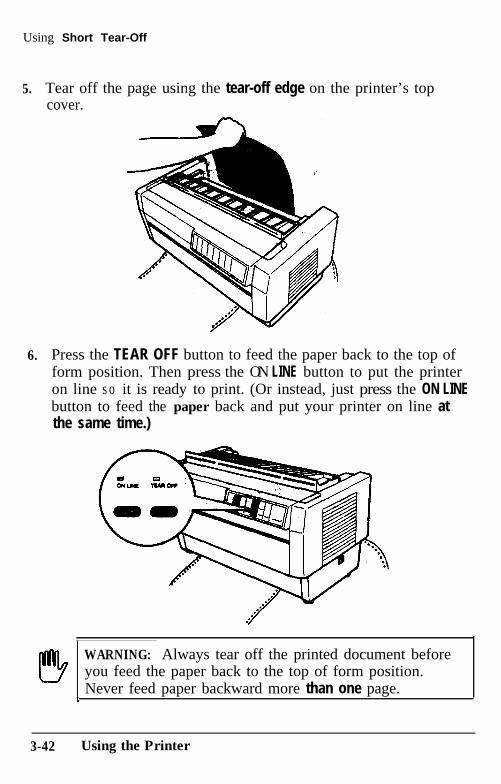
Using Short Tear-Off
5. Tear off the page using the tear-off edge on the printer’s topcover.
6. Press the TEAR OFF button to feed the paper back to the top ofform position. Then press the ON LINE button to put the printeron line s o it is ready to print. (Or instead, just press the ON LINEbutton to feed the paper back and put your printer on line atthe same time.)
WARNING: Always tear off the printed document beforeyou feed the paper back to the top of form position.Never feed paper backward more than one page.1
3-42 Using the Printer
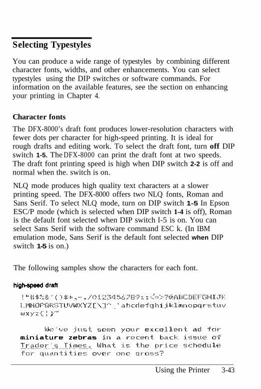
Selecting Typestyles
You can produce a wide range of typestyles by combining differentcharacter fonts, widths, and other enhancements. You can selecttypestyles using the DIP switches or software commands. Forinformation on the available features, see the section on enhancingyour printing in Chapter 4.
Character fonts
The DFX-8000’s draft font produces lower-resolution characters withfewer dots per character for high-speed printing. It is ideal forrough drafts and editing work. To select the draft font, turn off DIPswitch 1-5. The DFX-8000 can print the draft font at two speeds.The draft font printing speed is high when DIP switch 2-2 is off andnormal when the. switch is on.
NLQ mode produces high quality text characters at a slowerprinting speed. The DFX-8000 offers two NLQ fonts, Roman andSans Serif. To select NLQ mode, turn on DIP switch 1-5 In EpsonESC/P mode (which is selected when DIP switch 1-4 is off), Romanis the default font selected when DIP switch l-5 is on. You canselect Sans Serif with the software command ESC k. (In IBMemulation mode, Sans Serif is the default font selected when DIPswitch 1-5 is on.)
The following samples show the characters for each font.
Using the Printer 3-43
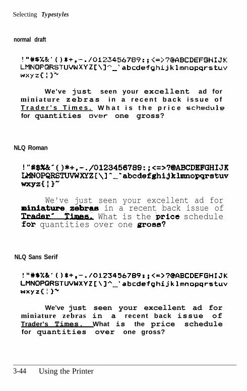
Selecting Typestyles
normal draft
!"#6%&'0$+,-./0123456789:~~~~~?~~EC~EFGHIJ~LMNOPQRSTUVW XY Z C \ I--’ abcdefghijklmnopq.rstuvwxyzI 1 3’+
We’ve just seen your excellent ad form i n i a t u r e zebras i n a r e c e n t b a c k i s s u e o fT r a d e r ’ s T i m e s . W h a t i s t h e p r i c e schedulefor quantities over one gross?
NLQ Roman
! “#$%%-( )*+,- ./0123456789:;<=>?@ABCI)$FGHIJKLMN0PQRSTWWXYZC\l*,'abcdefghijklmnopqmtuvWXYZC I)-
We've just seen your excellent ad forminiature.aebrga in a recent back issue of* Timee. What is the 'price schedulefob quantities over one prom?
NLQ Sans Serif
!“#b%& (I*+,-. /0123456789:;<=>?@QBCDEFGHIJKLMNOPQRSTUVWXYZC\]“-’ rbcdefghijklmnopqrstuvwxyzc : 1"
We’ve just seen your excellent ad forminiature zebras in a recent back issue ofTrader’s Times. What is the price schedulefor quantities over one gross?
3-44 Using the Printer
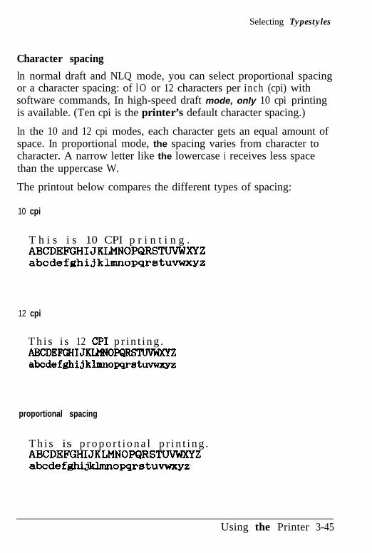
Selecting Typestyles
Character spacing
ln normal draft and NLQ mode, you can select proportional spacingor a character spacing: of l O or 12 characters per inch (cpi) withsoftware commands, In high-speed draft mode, only 10 cpi printingis available. (Ten cpi is the printer’s default character spacing.)
ln the 10 and 12 cpi modes, each character gets an equal amount ofspace. In proportional mode, the spacing varies from character tocharacter. A narrow letter like the lowercase i receives less spacethan the uppercase W.
The printout below compares the different types of spacing:
10 cpi
T h i s i s 10 CPI p r i n t i n g .ABCDEFGHIJKLMNOPQRSTWWKYZabcdefghijklmnopqrstuvwxyz
12 cpi
T h i s i s 12 CPI p r i n t i n g .ABCDEFGHI JKL<?OmZabodefghi jklmnopqratuvwxyz
proportional spacing
T h i s is p r o p o r t i o n a l p r i n t i n g .ABCDEFGHIJKLMNOPQRSTWWXYZabcdefghijklmnopqrstuvwxyz
Using the Printer 3-45
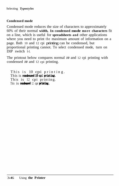
Selecting Typestyles
Condensed mode
Condensed mode reduces the size of characters to approximately60% of their normal width, In condensed mode more characters fiton a line, which is useful for spreadsheets and other applicationswhere you need to print the maximum amount of information on apage. Both 10 and 12 cpi printing can be condensed, butproportional printing cannot. To select condensed mode, turn onDIP switch l-l.
The printout below compares normal 10 and 12 cpi printing withcondensed 10 and 12 cpi printing.
T h i s i s 10 cpi p r i n t i n g .This is condensed 10 cpi printin&This is 12 cpi printing.This is condmed 12 cpi pridng.
3-46 Using the Printer
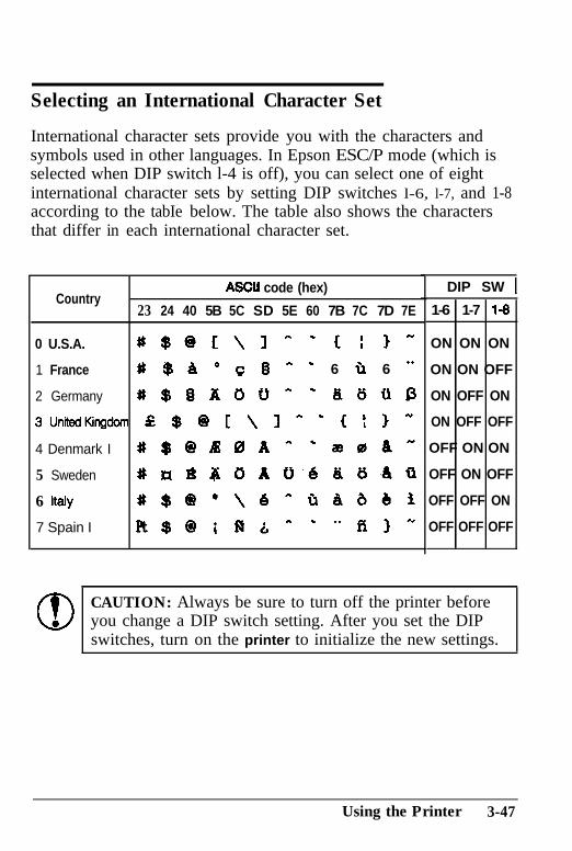
Selecting an International Character Set
DIP SW 1Country
ASCU code (hex)
23 24 40 5B 5C SD 5E 60 7B 7C 7D 7E 1-6 1-7 1-8
0 U.S.A. ~$oc\In‘cI~- ON ON ON
1 France # $8 o 0 Q * - 6 ix 6 . ON ON OFF
2 Germany #$f3AOU-‘&UtiD ON OFF ON
3UnitedKingdorr 52 $ @ [ \ 1 * L c ! 3 N ON OFF OFF
4 Denmark I #$@BBA”‘seA” OFF ON ON
5 Sweden YnB#bAU6&UAti OFF ON OFF
6 Italy #$@*\6ntiAbbi OFF OFF ON
7 Spain I Pt$@;fiA*--fi)” OFF OFF OFF
International character sets provide you with the characters andsymbols used in other languages. In Epson ESC/P mode (which isselected when DIP switch l-4 is off), you can select one of eightinternational character sets by setting DIP switches l-6, l-7, and 1-8according to the tabIe below. The table also shows the charactersthat differ in each international character set.
CAUTION: Always be sure to turn off the printer beforeyou change a DIP switch setting. After you set the DIPswitches, turn on the printer to initialize the new settings.
Using the Printer 3-47
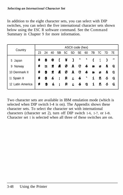
Selecting an International Character Set
In addition to the eight character sets, you can select with DIPswitches, you can select the five international character sets shownbelow using the ESC R software command. See the CommandSummary in Chapter 9 for more information.
CountryASCII code (hex)
23 24 40 5B 5C 5D 5E 60 7B 7C 7D 7E
5 Japan #$@cYl-‘cI~-
9 Norway #nBBBAU6zsrabU
10 Denmark II #$810AU6aabQ
11 Spain II #$bifi&6’iA66
12 Latin America # $6 i f4JL6tiifi6ti
Two character sets are available in IBM emulation mode (which isselected when DIP switch l-4 is on). The Appendix shows thesecharacter sets. To select the character set with internationalcharacters (character set 2), turn off DIP switch 1-6, 1-7, or l-8.Character set 1 is selected when all three of these switches are on.
3-48 Using the Printer
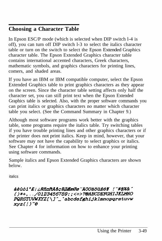
Choosing a Character Table
In Epson ESC/P mode (which is selected when DIP switch l-4 isoff), you can turn off DIP switch l-3 to select the italics charactertable or turn on the switch to select the Epson Extended Graphicscharacter table. The Epson Extended Graphics character tablecontains international accented characters, Greek characters,mathematic symbols, and graphics characters for printing lines,comers, and shaded areas.
If you have an IBM or IBM compatible computer, select the EpsonExtended Graphics table to print graphics characters as they appearon the screen. Since the character table setting affects only half thecharacter set, you can still print text when the Epson ExtendedGraphics table is selected. Also, with the proper software commands youcan print italics or graphics characters no matter which charactertable you select. (See the Command Summary in Chapter 9.)
Although most software programs work better with the graphicstable, some programs require the italics table. Try switching tablesif you have trouble printing lines and other graphics characters or ifthe printer does not print italics. Keep in mind, however, that yoursoftware may not have the capability to select graphics or italics.See Chapter 4 for information on how to enhance your printingusing software commands.
Sample italics and Epson Extended Graphics characters are shownbelow.
italics
d&tiidi “E; L4Midti4d~~~0 -~&tx&l-ci~~~Y ! “#$A% -
o*+, - -/U12345678~:;cr=~?~BCDE~HIJKLMNOPQRSTUVWXl?ZT\J*, 'abcdefghijklmnopqrstuvwxYzc,‘3-@
Using the Printer 3-49
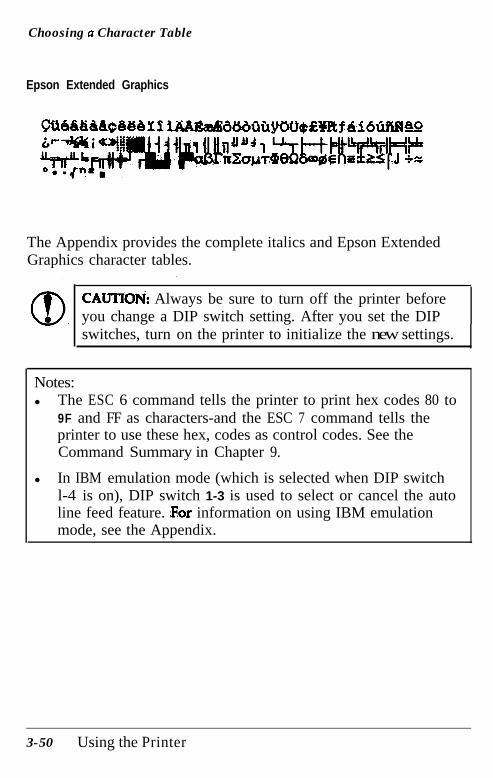
Choosing a Character Table
Epson Extended Graphics
The Appendix provides the complete italics and Epson ExtendedGraphics character tables.
!
CAUTIOb& Always be sure to turn off the printer beforeyou change a DIP switch setting. After you set the DIPswitches, turn on the printer to initialize the new settings.
Notes:l The ESC 6 command tells the printer to print hex codes 80 to
9F and FF as characters-and the ESC 7 command tells theprinter to use these hex, codes as control codes. See theCommand Summary in Chapter 9.
l In IBM emulation mode (which is selected when DIP switchl-4 is on), DIP switch 1-3 is used to select or cancel the autoline feed feature. information on using IBM emulationmode, see the Appendix.
3-50 Using the Printer
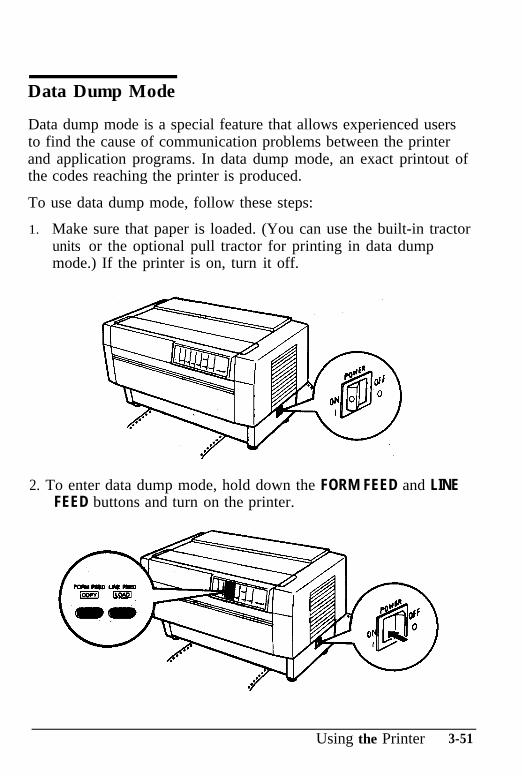
Data Dump Mode
Data dump mode is a special feature that allows experienced usersto find the cause of communication problems between the printerand application programs. In data dump mode, an exact printout ofthe codes reaching the printer is produced.
To use data dump mode, follow these steps:
1.. Make sure that paper is loaded. (You can use the built-in tractorunits or the optional pull tractor for printing in data dumpmode.) If the printer is on, turn it off.
2. To enter data dump mode, hold down the FORM FEED and LINEFEED buttons and turn on the printer.
Using the Printer 3-51
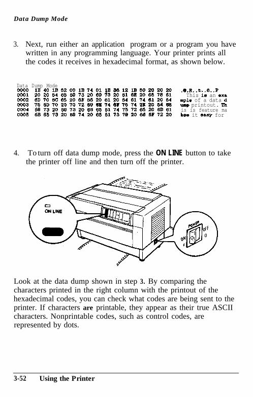
Data Dump Mode
3. Next, run either an application program or a program you havewritten in any programming language. Your printer prints allthe codes it receives in hexadecimal format, as shown below.
Data Dump Mode0000 1B 40 1B 52 00 1B 74 01 lB 36 12 1B 50 20 20 20 .e.R..t..e..P0001 20 20 54 66 69 73 20 69 73 20 61 62 20 65 76 61 This is an exa0002 6D 70 6C 65 20 6P 66 20 61 20 64 61 74 61 20 64 mple of a data d0003 75 6D 70 20 70 72 09 6S 74 6F 76 74 2P 20 54 66 Imp printout. Th0004 69 73 20 69 73 20 66 66 61 74 76 72 65 20 6D 61 is is feature ma0005 6B 65 73 20 69 74 20 65 61 73 79 20 60 6F 72 20 kw it easy for
4.. To turn off data dump mode, press the ON LINE button to takethe printer off line and then turn off the printer.
Look at the data dump shown in step 3. By comparing thecharacters printed in the right column with the printout of thehexadecimal codes, you can check what codes are being sent to theprinter. If characters are printable, they appear as their true ASCIIcharacters. Nonprintable codes, such as control codes, arerepresented by dots.
3-52 Using the Printer
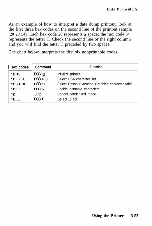
Data Dump Mode
As an example of how to interpret a data dump printout, look atthe first three hex codes on the second line of the printout sample(20 20 54). Each hex code 20 represents a space; the hex code 54represents the letter T. Check the second line of the right columnand you will find the letter T preceded by two spaces.
The chart below interprets the first six nonprintable codes.
1 Hex codes Command
1B 40 ESC @1B 52 00 ESC R 01B 74 01 ESC t 11B 36 ESC 612 DC21B 50 ESC P
Function
Initialize printerSelect USA character setSelect Epson Extended Graphics character tableEnable printable charactersCancel condensed modeSelect 10 cpi
Using the Printer 3-53
Chapter 4Software and Graphics
Enhancing Your Printing ............................................ 4-2Print quality and fonts ............................................ 4-2Character spacing .................................................. 4-3Character size ....................................................... 4-4Special effects and emphasis ..................................... 4-5Selecting typestyles with Master Select ....................... 4-8
Graphics ................................................................. 4-10The print head ...... ..? ............................................. 4-11The graphics commands .......................................... 4-13Column reservation numbers .................................... 4-14Printing simple patterns .......................................... 4-14Printing taller patterns ............................................ 4-16Designing your, own graphics ................................... 4-17Individual graphics commands .................................. 4-20The reassignment command ..................................... 4-20
User-defined Characters .............................................. 4-22Designing your characters ........................................ 4-23Sending information to your printer .......................... 4-24Printing user-defined characters ................................ 4-26Copy ROM characters to RAM ................................ 4-27Mixing print styles ................................................. 4-28
Software and Graphics 4-1
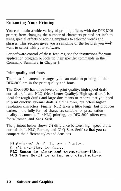
Enhancing Your Printing
You can obtain a wide variety of printing effects with the DFX-8000printer, from changing the number of characters printed per inch tousing special effects or adding emphasis to selected words andphrases. This section gives you a sampling of the features you ina$want to select with your software.
For software control of these features, see the instructions for yourapplication program or look up their specific commands in the.Command Summary in Chapter 9.
Print quality and fontsThe most fundamental changes you can make to printing on theDFX-8000 are in the print quality and fonts.
The DFX-8000 has three levels of print quality: high-speed draft,normal draft, and NLQ (Near Letter Quality). High-speed draft isideal for rough drafts and large documents or reports that you needto print quickly. Normal draft is a bit slower, but offers higherresolution characters. Finally, NLQ takes a little longer but producesdarker, more fully-formed characters suitable for presentation-quality documents. For NLQ printing, the DFX-8000 offers twofonts-Roman and Sans Serif.
The printout below shows the difference between high-speed draft,normal draft, NLQ Roman, and NLQ Sans Serif so that you cancompare the different styles and densities.
4-2 Software and Graphics
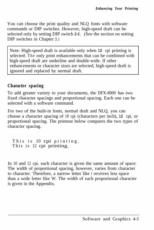
Enhancing Your Printing
You can choose the print quality and NLQ fonts with softwarecommands or DIP switches. However, high-speed draft can beselected only by setting DIP switch 2-2. (See the section on settingDIP switches in Chapter 3.)
Note: High-speed draft is available only when 10 cpi printing isselected: The only print enhancements that can be combined withhigh-speed draft are underline and double-wide. If otherenhancements or character sizes are selected, high-speed draft isignored and replaced by normal draft.
Character spacingTo add greater variety to your documents, the DFX-8000 has twofixed character spacings and proportional spacing. Each one can beselected with a software command.
For two of the built-in fonts, normal draft and NLQ, you canchoose a character spacing of 10 cpi (characters per inch), 12 cpi, orproportional spacing. The printout below compares the two types ofcharacter spacing.
T h i s i s 10 cpi p r i n t i n g .T h i s i s 12 cpi printing.
In 10 and 12 cpi, each character is given the same amount of space.The width of proportional spacing, however, varies from characterto character. Therefore, a narrow letter like i receives less spacethan a wide letter like W. The width of each proportional characteris given in the Appendix.
Software and Graphics 4-3
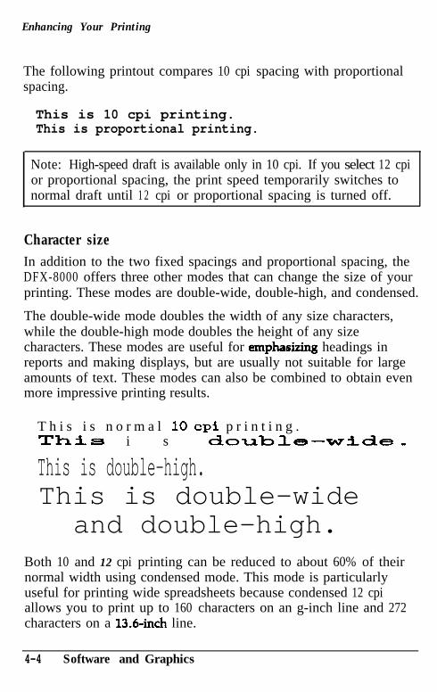
Enhancing Your Printing
The following printout compares 10 cpi spacing with proportionalspacing.
This is 10 cpi printing.This is proportional printing.
Note: High-speed draft is available only in 10 cpi. If you select 12 cpior proportional spacing, the print speed temporarily switches tonormal draft until 1 2 cpi or proportional spacing is turned off.
Character sizeIn addition to the two fixed spacings and proportional spacing, theDFX-8000 offers three other modes that can change the size of yourprinting. These modes are double-wide, double-high, and condensed.
The double-wide mode doubles the width of any size characters,while the double-high mode doubles the height of any sizecharacters. These modes are useful for emphasizing headings inreports and making displays, but are usually not suitable for largeamounts of text. These modes can also be combined to obtain evenmore impressive printing results.
T h i s i s n o r m a l 10 cpi p r i n t i n g .ThiS i s double-wide,
This is double-high.This is double-wide
and double-high.Both 10 and 12 cpi printing can be reduced to about 60% of theirnormal width using condensed mode. This mode is particularlyuseful for printing wide spreadsheets because condensed 12 cpiallows you to print up to 160 characters on an g-inch line and 272characters on a 136inch line.
4-4 Software and Graphics
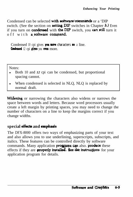
Enhancing Your Printing
Condensed can be selected with.sokwar@c&nr&A or a ‘DIPswitch. (See the section on settingDIP switches in Chapter 3.1 Evenif you turn on candensed with the.DIP switch, you can,still turn ito f f w i t h a:software cammand.
Condensed 10 cpi gives ys~ more characters os a line.cordsplled 12 cpi qea you CTCI more.
Notes:l Both 10 and 12 cpi can be condensed, but proportional
spacing cannot.
l When condensed is selected in NLQ, NLQ is replaced bynormal draft.
W&ning or narrowing the characters also widens or narrows thespace between words and letters. Because word processors usuallycreate a left margin by printing spaces, you may need to change thenumber of characters on a line to keep the margins correct if youchange widths.
special efkcta and emphasisThe DFX-8000 offers two ways of emphasizing parts of your textand also allows you to use underlining, superscripts, subscripts, anditalics. These features can be controlled directly by softwarecommands. Many application prowarns cq also. pro&ce theseeffects if they are grqeriy instalk& &et&z instru#ons for yourapplication program for details.
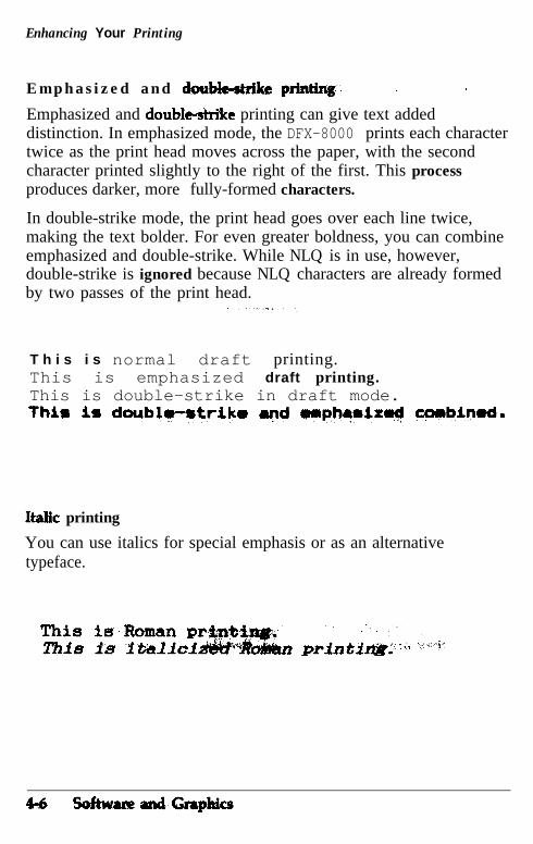
Enhancing Your Printing
E m p h a s i z e d a n d &&ktrike prkting, , j
Emphasized and double-striie printing can give text addeddistinction. In emphasized mode, the DFX-8000 prints each charactertwice as the print head moves across the paper, with the secondcharacter printed slightly to the right of the first. This processproduces darker, more fully-formed characters.
In double-strike mode, the print head goes over each line twice,making the text bolder. For even greater boldness, you can combineemphasized and double-strike. While NLQ is in use, however,double-strike is ignored because NLQ characters are already formedby two passes of the print head.
T h i s i s normal draft printing.This is emphasized draft printing.This is double-strike in draft mode.thir is doublT-rtrikr ayvd HII~~IIZ~ ccmbipmd.
Italk printing
You can use italics for special emphasis or as an alternativetypeface.
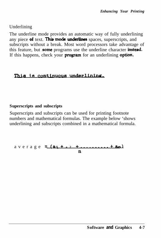
Enhancing Your Printing
Underlining
The underline mode provides an automatic way of fully underliningany piece of text. Thimnode urdeh spaces, superscripts, andsubscripts without a break. Most word processors take advantage ofthis feature, but .some programs use the underline character *stead.If this happens, check your prqqam for an underlining optiori.
jR cn
Superscripts and subscripts
Superscripts and subscripts can be used for printing footnotenumbers and mathematical formulas. The example below ‘showsunderlining and subscripts combined in a mathematical formula.
a v e r a g e = .L~I + a 2 + -.------.- + n=ln
Software and Graphics 4-7
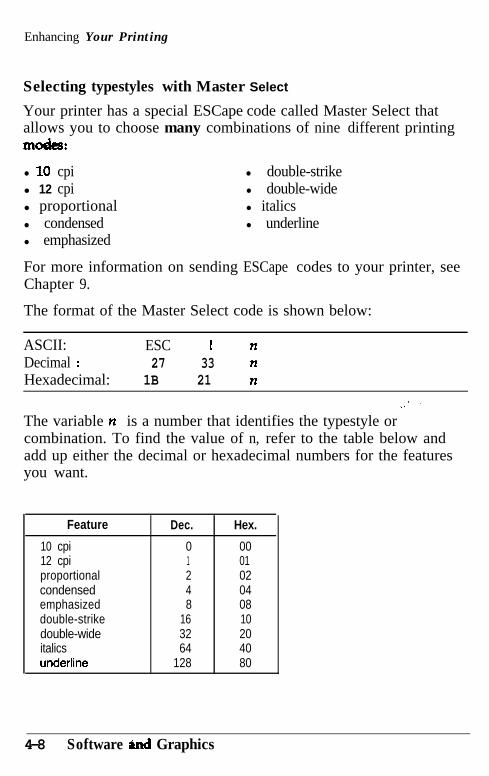
Enhancing Your Printing
Selecting typestyles with Master Select
Your printer has a special ESCape code called Master Select thatallows you to choose many combinations of nine different printinglllOdC3:
l 10 cpil 12 cpil proportionall condensedl emphasized
l double-strikel double-widel italicsl underline
For more information on sending ESCape codes to your printer, seeChapter 9.
The format of the Master Select code is shown below:
ASCII: ESC ! nDecimal : 27 33 nHexadecimal: 1B 21 n
The variable n is a number that identifies the typestyle orcombination. To find the value of n, refer to the table below andadd up either the decimal or hexadecimal numbers for the featuresyou want.
Feature Dec. Hex.
10 cpi 0 0012 cpi 1 01proportional 2 02condensed 4 04emphasized 8 08double-strike 16 10double-wide 32 20italics 64 40undertine 128 80
4-8 Software and Graphics
Enhancing Your Printing
For example, to print a title you may want to use double-wide 12 cpicharacters and print them in double-strike mode. You would-addthese three decimal numbers together to calculate the value of n. l2 cpi 1’ . .Double-strike 16Double-wide 32-
n = 49
After calculating the value of n, you would use the Master Selectcommand to send the value to the printer.
ASCII: ESC I 1I
Decimal: 27 33 49Hexadecimal: 1B 21 31
Print quality and font selection are not part of.Master Select andmust be set separately, using the ESC x and ESC k commands. Thedraft font printing speed must be set using DIP switch 2-2. (See thesection ‘on ‘setting DIP switches in Chapter 3.)
There are four more things to cons@er when using the Master Selectcommand:
Master Select cancels any of th&list& f&u-es that you do notset. For example, if you have.,&eadjl W&2 cpi, and you try touse Master Select to set emph& ,+$&-strike only, thecharacter spacing is reset to 10 &I.
Proportional spa% overrides 10 cpi,. 1 2 cpi, and condensed. Only 10 cpi, under&pe, and double-i&de are available in high-speed draft mode.
When emphasized and condensed are selected, emphasized isignored.
Software and Graphics 4-9
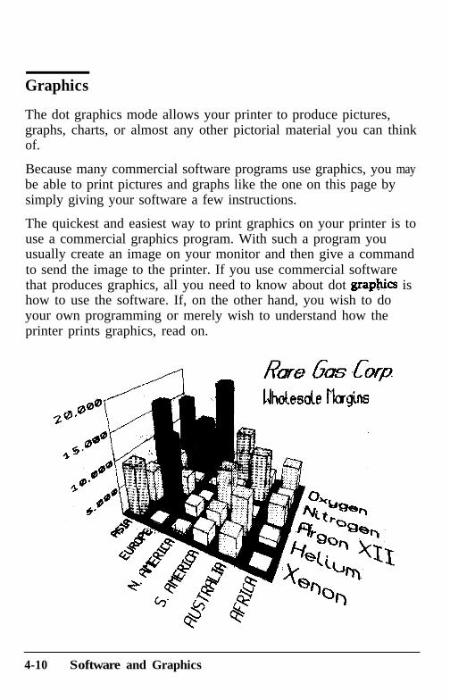
Graphics
The dot graphics mode allows your printer to produce pictures,graphs, charts, or almost any other pictorial material you can thinkof.
Because many commercial software programs use graphics, you maybe able to print pictures and graphs like the one on this page bysimply giving your software a few instructions.
The quickest and easiest way to print graphics on your printer is touse a commercial graphics program. With such a program youusually create an image on your monitor and then give a commandto send the image to the printer. If you use commercial softwarethat produces graphics, all you need to know about dot graph@ ishow to use the software. If, on the other hand, you wish to doyour own programming or merely wish to understand how theprinter prints graphics, read on.
4-10 Software and Graphics
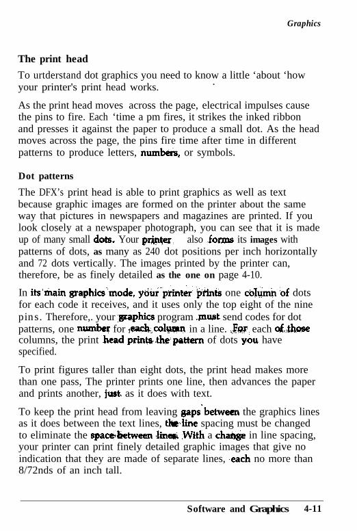
Graphics
The print head
To urtderstand dot graphics you need to know a little ‘about ‘howyour printer's print head works. .
As the print head moves across the page, electrical impulses causethe pins to fire. Each ‘time a pm fires, it strikes the inked ribbonand presses it against the paper to produce a small dot. As the headmoves across the page, the pins fire time after time in differentpatterns to produce letters, number& or symbols.
Dot patterns
The DFX’s print head is able to print graphics as well as textbecause graphic images are formed on the printer about the sameway that pictures in newspapers and magazines are printed. If youlook closely at a newspaper photograph, you can see that it is madeup of many small dots, Your PIT&@; also .forms its images withpatterns of dots, as many as 240 dot positions per inch horizontallyand 72 dots vertically. The images printed by the printer can,therefore, be as finely detailed as the one on page 4-10.
In its’main @aphics”mode, ydur’prir& ‘tiiints one co&&‘-of dotsfor each code it receives, and it uses only the top eight of the ninepins. Therefore,. your ,graphics program muat send codes for dotpatterns, one numb for ~each.,colurnn in a line. .l$o.r each o&hosecolumns, the print .head printa-the.pattern of dots -you havespecified.
To print figures taller than eight dots, the print head makes morethan one pass, The printer prints one line, then advances the paperand prints another, just, as it does with text.
To keep the print head from leaving gaps‘between the graphics linesas it does between the text lines, tho,line spacing must be changedto eliminate the space&etween <lined ,With a cw in line spacing,your printer can print finely detailed graphic images that give noindication that they are made of separate lines, ‘each no more than8/72nds of an inch tall.
Software and Graphics 4-11
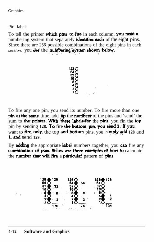
Graphics
Pin labels
To tell the printer whiih,,.pins ,to.&e in each column, )rou ne&anumbering system that separately ident$fies ewh of the eight pins.Since there are 256 possible combinations of the eight pins in eachsection, you use the ,*Geriri&‘b#km shiM W&y. ’
ir : 1 :
128
E18
:21 I .''-.'.
To fire any one pin, you send its number. To fire more than onep‘in at tktim& time, add +p the nurtilk~ of the pins and ‘send’ thesum to the pfiter. VVW ‘tl\esc 1&&4&r the piA, you fin the ioppin by sending 128. To fire the b&ttoti *pin; yoti ‘M&&l l.“If youwant to irq ,only. the top qnd.bott?m pins, you ,siq\pb @d 128 andI, and send 129.
By addii the appropriate label numbers together, you dan fire anycom&Aation’ C&~&U. Mow are’thrke extipld d h& to calculatethe number t&tit tili,$ire a particulati pattern of -$ink
4-12 Software and Graphics
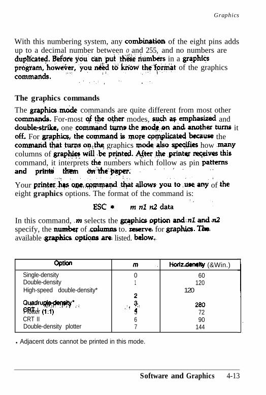
Graphics
With this numbering system, any combinatkqn of the eight pins addsup to a decimal number between 0 and 255, and no numbers aredup&ate$. Beke $6~ C&I pd ‘,$I!& riumbeks in a grs)phicspr&rati, h&&er, ‘you n&d t&‘iuiow ~l$@-+i~t of the graphicscommands* !-a’ . /‘. I’ ‘. i
,/‘, ” . ._
The graphics commands
The gra&ics.m6de commands are quite different from most othercommapds. For-most c$ #e c$her modes, a@~ ap. emphatied anddoubkst&, one co-d turns&e modqpn a& anc#he.r tums itoff+ For g~aphicsi the commaqd is. WoKe q~~@cated because thecomgn~d t+t ,turps qn,thq graphics mode,Jso qpeqifies how manycolumns of grap@F &l .be p$nted. After .* .prinW *v$!s thiscommand, it interprets the numbers which follow as pin patternsand p&,d tha f&+-- ,I- ( ’ ’ : .:
“‘1 ., 8’ .,Your pri+w,hv, QJJC’&I@ &at allows yoi to ,use angr of theeight graphics options. The format of the command is:
ESC* mnltidata ” ‘,
In this command, .m selects the gaqphics option andin and?&specify, the mm&r of r&mns to. reserve.L for graphias. ‘1Jre.available igraphics .optig~~ are listed. balowS7.
Optian m . . Hcuir.den8lQ (&Win.)
Single-density 0 60Double-density 1 120High-speed double-density* 120
W$u~*,.: :: ;< 2 4 0 80Plotter (1:l) ,/ 5 72CRT II 6 90Double-density plotter 7 144
l Adjacent dots cannot be printed in this mode.
Software and Graphics 4-13
Graphics
Even in single-density graphics mode, one 8-inch line can accommodate480 columns of graphics; jr( quadruple-density, almost 2OOO columnscan fit on the same g-inch Bne. Since the &inter does not usedecimal numbers larger than 255, the graphics mode command usestwo numbers for reserving columns.
To figure nl and n2, divide the total number of columns by 256.The result is ir2; the’ remainder is nl. Since the command is set upfor two numbers, you must supply two even if you need only one.When you need fewer ti& 256 cohmms, just make nl the numberof cohunns you are resa+@ and make &a zero. For example, ifyou wish to &cl 1632 c6lumns of .gr&phica data; nl should be 96andn2shouldbebl+rusel632 - % + (6 x 256).
If you are using a programming language with MOD (modulus) andINT (integer) functions, you can use the following formulas tocalculitte rr2 <title, in tiki& ti is- the tad iitixW& ~9 columns:
: ,”nl = nMOD256?I2 - INT (n/256)
The print& will’ i&!rpre+ f the ntimber of by& det&&ed ‘by nl andn2 as grapWs data; no titter i&at codes ;+liey are. This meansthat you must be sure to suppI)? tiugh by&s’ of gra#&x data orthe printer will stop and wait for more data and will seem to belocked. If, on the other hand, you supply too much graphics data,the excess v&l be interpreted and printed as regular text.
Printing sisnple patterns
The first ex&tple is just a’ s&&program to show you how thegraphics command, column reservation numbers, and data can beused in a BASIC program.
4-14 Software and Graphics
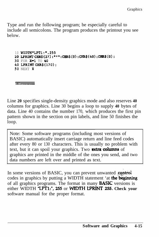
Graphics
Type and run the following program; be especially careful toinclude all semicolons. The program produces the printout you seebelow.
10 WIDTH"LPT1:".25520 LPRINTCIiR$(27):"*":CHR$(O):CHR$(4O):CRR$(0);30 FOR Xtl TO 4040 LPRINTCHR$(170):50 NEXT X
:.---“..-
Line 20 specifies single-density graphics mode and also reserves 40columns for graphics. Line 30 begins a loop to supply 40 bytes ofdata. Line 40 contains the number 170, which produces the first pinpattern shown in the section on pin labels, and line 50 finishes theloop.
Note: Some software programs (including most versions ofBASIC) automatically insert carriage return and line feed codesafter every 80 or 130 characters. This is usually no problem withtext, but it can spoil your graphics. Two extra-cohnnns ofgraphics are printed in the middle of the ones you send, and twodata numbers are left over and printed as text.
In some versions of BASIC, you can prevent unwanted ,co$rolcodes in graphics by putting a WIDTH statement ‘at thebeginningof all graphics programs. The format in many BASK versions iseither WIDTH ZPTl:“, 255 or WIDTH LPRINT 255. Check yoursoftware manual for the proper format.
Software and Graphics 4-15
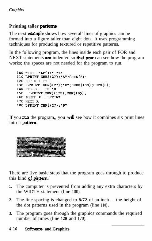
Graphics
Printing taller pattm
The next examtile shows how several’ lines of graphics can beformed into a figure taller than eight dots. It uses programmingtechniques for producing textured or repetitive patterns.
In the following program, the lines inside each pair of FOR andNEXT statements ara indented so that:you, can see how the programworks; the spaces are not needed for the program to run.
100 WIDTH "LPT1:",255110 LPRINT CHR$(27):"A":CHR$(S):120 FOR R-l TO 6130 LPRINT CHR$(27):"K":CHR$(lOO):CHR$(O~:140 FOR X-l TO 50150 LPRINT CHR$(170);CHR$(85):160 NEXT X : LPRINT170 NEXT R180 LPRINT CHR$(27);"0"
If you rtm the program,, you .will see bow it combines six print linesinto a pattern.
There are five basic steps that the program goes through to producethis kind of!!pa>te+:
1. The computer is prevented from adding any extra characters bythe WIDTH statement (line 100).
2. The line spacing is changed to 8/72 of an inch - the height ofthe dot patterns used in the program (line 110).
3. The program goes through the graphics commands the requirednumber of times (line 120 and 170).
4-16 Software and Graphics
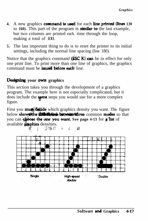
Graphics
4.. A new graphics command-isused for each 1ine:printed (hnes 130to 160). This part of the program is simihrto the last example,but two columns are printed each. time through the loop,making a total of 100.
5. The last important thing to do is to reset the printer to its initialsettings, including the normal line spacing (line 180).
Notice that the graphics command (& K)can be in effect for onlyone print line. To print more than one line of graphics, the graphicscommand must be isiniisd b&fore ea& line.
Desigming your owe graphics
This section takes you through the development of a graphicsprogram. The example here is not especially complicated, but itdoes include the ye steps you would use for a more complexfigure.
First you mug$&&ide which graphics density you want. The figurebelow show$$he b .;! &WVW#U~~ common m&s so thatyou can cg&ose t one, y&u ,want. See page 4-13 for ,$Iist ofavailable &phics densities.
‘g ,j, ,J;‘t’@;f,i “‘, ,i, .;g;<I
Software and Graphics 4-17
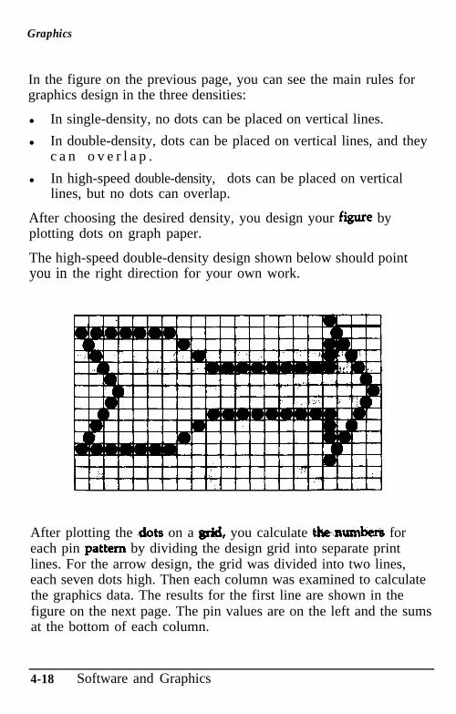
Graphics
In the figure on the previous page, you can see the main rules forgraphics design in the three densities:
l In single-density, no dots can be placed on vertical lines.
l In double-density, dots can be placed on vertical lines, and theyc a n o v e r l a p .
l In high-speed double-density, dots can be placed on verticallines, but no dots can overlap.
After choosing the desired density, you design your fiie byplotting dots on graph paper.
The high-speed double-density design shown below should pointyou in the right direction for your own work.
After plotting the <dots on a g&l, you calculate thenumbers foreach pin pattern by dividing the design grid into separate printlines. For the arrow design, the grid was divided into two lines,each seven dots high. Then each column was examined to calculatethe graphics data. The results for the first line are shown in thefigure on the next page. The pin values are on the left and the sumsat the bottom of each column.
4-18 Software and Graphics
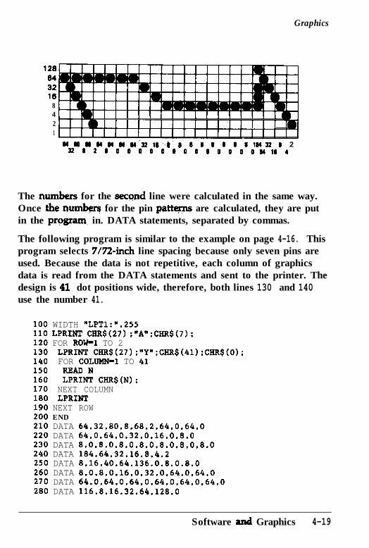
Graphics
12a6432168421
I
1-1 I I I 1 1 1 I I 1 I ,
1101111111111111111
44wwuMwa422l(I~t:8 8 8 0 I8 8184228 2228200000000000000Ml44
The numberg for the second line were calculated in the same way.Once the numbeq for the pin patty are calculated, they are putin the pqgram. in. DATA statements, separated by commas.
The following program is similar to the example on page 4-16. Thisprogram selects 7/7%inch line spacing because only seven pins areused. Because the data is not repetitive, each column of graphicsdata is read from the DATA statements and sent to the printer. Thedesign is 41 dot positions wide, therefore, both lines 130 and 140use the number 41.
100 WIDTH "LPT1:".255110 LPRINT CIiR$(27) ;"A";CIIR$(7);120 FOR ROW-1 TO 2130 LPRINT CHR$(27):"Y":CHR$(41):CHR$(O):140 FOR COLDMN-1 TO 41150 READ N160 LPRINT CHR$(N):170 NEXT COLUMN180 LPRINT190 NEXT ROW200 END210 DATA 64.32.80.8.68.2.64.0.64.0220 DATA 64.0.64.0.32.0.16.0.8.0230 DATA 8.0.8.0,8.0.8.0.8.0.8,0,8,0240 DATA 184.64.32.16.8.4.2250 DATA 8.16.40.64.136.0.8.0.8.0260 DATA 8,0.8,0.16.0.32.0,64.0.64.0270 DATA 64.0.64.0.64.0.64.0.64.0.64.0280 DATA 116.8.16.32.64.128.0
Software and Graphics 4-19
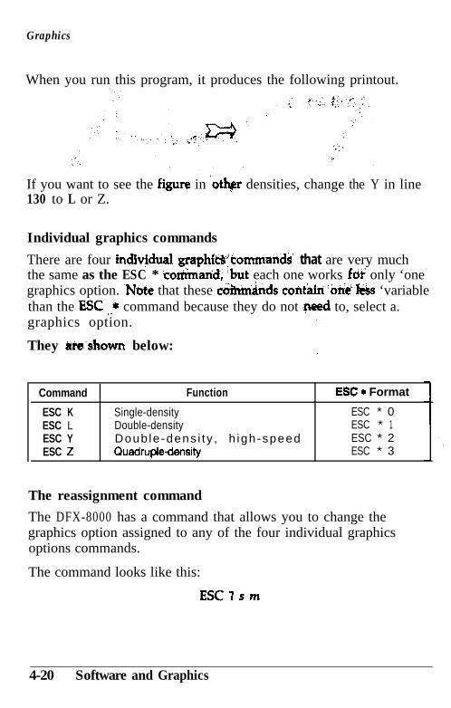
Graphics
When you run this program, it produces the following printout.
If you want to see the fiiure in ‘otbr densities, change the Y in line130 to L or Z.
Individual graphics commands
There are four indiv@ual graphf~‘tommands” that are very muchthe same as the ESC * co&arid, %ut each one works ‘for only ‘onegraphics option. .Note that these c&ttri&ds contam ~one?&s ‘variablethan the ESC .A* command because they do not .need to, select a.graphics option. I.
They irie’shown below: I
Command
ESC KESC LESC YESC Z
Function
Single-densityDouble-densityDoub le -dens i ty , h igh-speedQuadruple-density
ESC + Format
ESC * 0ESC * 1ESC * 2ESC * 3
The reassignment command
The DFX-8000 has a command that allows you to change thegraphics option assigned to any of the four individual graphicsoptions commands.
The command looks like this:
ESC sm
4-20 Software and Graphics
Graphics
The letter s represents the command that you wish to we theassignment for (K, L, Y, or Z) and m is the number of the graphicsoption that you want to assign &I it,. For example, to w theESC K command to use the CRT I graphics option, the command inBASIC is:
LPRINT CHR!$(27);‘?“;X”;CHR$(Q)
This is a quick way to change the aspect ratio of the design thatyou are printing. Cha@ing the graphics option will change thewidth without changing the height.
Software and Graphics 4-21
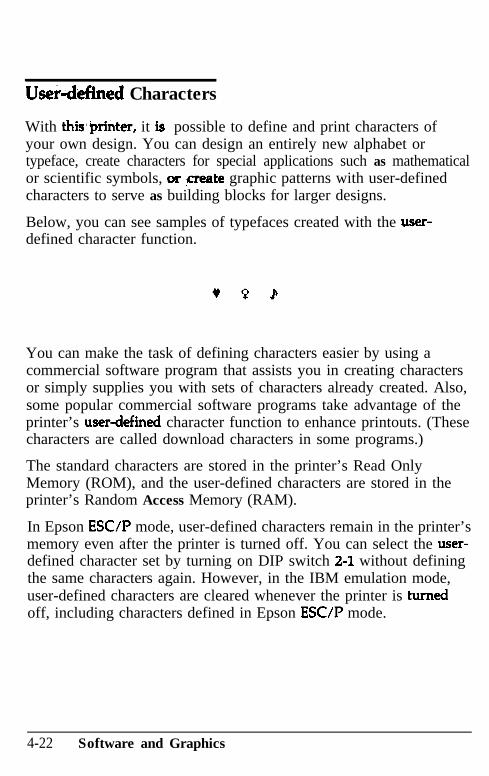
Userdefined Characters
With thisaprinter, it is possible to define and print characters ofyour own design. You can design an entirely new alphabet ortypeface, create characters for special applications such as mathematicalor scientific symbols, or ,create graphic patterns with user-definedcharacters to serve as building blocks for larger designs.
Below, you can see samples of typefaces created with the user-defined character function.
You can make the task of defining characters easier by using acommercial software program that assists you in creating charactersor simply supplies you with sets of characters already created. Also,some popular commercial software programs take advantage of theprinter’s userdefined character function to enhance printouts. (Thesecharacters are called download characters in some programs.)
The standard characters are stored in the printer’s Read OnlyMemory (ROM), and the user-defined characters are stored in theprinter’s Random Access Memory (RAM).
In Epson ESUP mode, user-defined characters remain in the printer’smemory even after the printer is turned off. You can select the user-defined character set by turning on DIP switch 2-l without definingthe same characters again. However, in the IBM emulation mode,user-defined characters are cleared whenever the printer is turnedoff, including characters defined in Epson ESC/P mode.
4-22 Software and Graphics
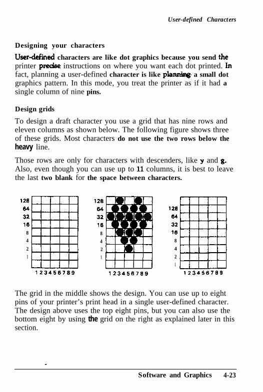
User-defined Characters
Designing your characters
Userdeked characters are like dot graphics because you send the-printer pm&e instructions on where you want each dot printed. Infact, planning a user-defined character is like planniqg a small dotgraphics pattern. In this mode, you treat the printer as if it had asingle column of nine pins.
Design grids
To design a draft character you use a grid that has nine rows andeleven columns as shown below. The following figure shows threeof these grids. Most characters do not use the two rows below theheavy line.
Those rows are only for characters with descenders, like y and g.Also, even though you can use up to 11 columns, it is best to leavethe last two blank for the space between characters.
128
64321684
21
123456789 123456789 123456789
12864
32168421
L i i i i I
12864
32168421
The grid in the middle shows the design. You can use up to eightpins of your printer’s print head in a single user-defined character.The design above uses the top eight pins, but you can also use thebottom eight by using the grid on the right as explained later in thissection.
.
Software and Graphics 4-23
User-defined Characters
Sending information to your printer
Once the -character is planned on the grid, you simply add the pinvalues for each column together, just as you do for graphics. Thelast step in defMng ,a character is to send this information to theprinter.
The command to define characters is relatively complex:
ESC & 0 nl n2 al dz . . . dn
You can define more than one character with a single command.The values nl and ti are the ASCII codes of the first and lastcharacters you are defining. If you are defining only one character,n7 and n2 are the same. You can use any codes between 0 and 255
decimal for nl and n2 except the following codes: 7, 8, 9, 10, 11;12, 13, 14, 15, 18, 19, 20, 24, and 27 decimal. Also, it is best not todefine decimal 32, which is the code for a space.
You can also use other codes by using the ESC 6 and ESC Icommands. (See the Command Summary in Chapter 9.)
For example, if you wanted to redefine the characters A through Z,n7 would be A (or ASCII code 65) and n2 would be Z (or ASCIIcode 90). So the command ESC ,h 0 AZ (followed by the appropriatedata) would replace the characters A through Z.
Following the specification of the range of characters to be definedin this command is one number (al) that specifies the width of thecharacter and whether it uses the top eight pins or the bottom eightpins.
The last part of the command (d1.. .dn) is the actual data thatdefines the dot patterns for each column of each character. Since acharacter can use up to eleven columns, you must supply elevendata numbers for each character even if some columns are blank.
Note: Be sure to turn off DIP switch 2-l before definingcharacters. The ESC & command is invalid if this switch is on.
4-24 Software and Graphics
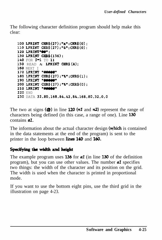
User-defined Characters
The following character definition program should help make thisclear:
:“x”:CHR$(O) :;"&";CHR$(O);
1;
100 LPRINT CHR$f27)110 LPRINT CHR$(27)120 LPR1NlY.V:130 LPRINT 'X$2$(136140 FOR I=1 TO 11150 READ A: LPRINT160 NEXT I170 LPRINT "@W@@"
CHRS (A) :
180 LPRINT CHR$(27,:"X";CHR$(l):190 LPRINT V0.W'200 LPRINT CHR$(27);"X":CHR$(O):210 LPRINT "eieo@"220 END230 DATA 32.80.168.84,42.84.168.80,32.0.0
The two at signs (Q) in line 120 (no and ti) represent the range ofcharacters being defined (in this case, a range of one). Line 130contains al.
The information about the actual character design (which is containedin the data statements at the end of the program) is sent to theprinter in the loop between hnes 140 and 160.
Sped&ngthewid&andheight
The example program uses 136 for al (in line 130 of the definitionprogram), but you can use other values. The number al specifiestwo things: the width of the character and its position on the grid.The width is used when the character is printed in proportionalmode.
If you want to use the bottom eight pins, use the third grid in theillustration on page 4-23.
Software and Graphics 4-25
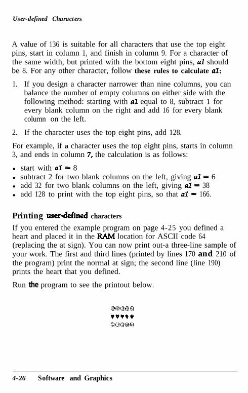
User-defined Characters
A value of 136 is suitable for all characters that use the top eightpins, start in column 1, and finish in column 9. For a character ofthe same width, but printed with the bottom eight pins, al shouldbe 8. For any other character, follow these rules to calculate al:
1. If you design a character narrower than nine columns, you canbalance the number of empty columns on either side with thefollowing method: starting with al equal to 8, subtract 1 forevery blank column on the right and add 16 for every blankcolumn on the left.
2.. If the character uses the top eight pins, add 128.
For example, if a character uses the top eight pins, starts in column3, and ends in column 7, the calculation is as follows:
l start with al = 8l subtract 2 for two blank columns on the left, giving al = 6l add 32 for two blank columns on the left, giving al = 38l add 128 to print with the top eight pins, so that al = 166.
Printing userdefined characters
If you entered the example program on page 4-25 you defined aheart and placed it in the RAIvI location for ASCII code 64(replacing the at sign). You can now print out-a three-line sample ofyour work. The first and third lines (printed by lines 170 and 210 ofthe program) print the normal at sign; the second line (line 190)prints the heart that you defined.
Run the program to see the printout below.
4-26 Software and Graphics
User-defined Characters
As you can see, both sets of characters (the original ROMcharacters that the printer normally uses and the user-definedcharacter set) remain in the printer available for your use. Thecommand to switch between the two sets is used in line 180 and200. It is:
ESC % n
If n is equal to 0, the normal ROM character set is selected. If R isequal to 1, the userdefined character set is selected. You can alsoselect one of the two character sets with DIP switch 2-1. If youselect the user-defined character set before you have defined anycharacters, the command is ignored and the ROM characters remainin use.
You may switch between character sets at any time, even in themiddle of a line. To try this, place semicolons at the end of lines170 and 190 in the preceding program.
Copying ROM characters to RAM
After nmning the previous sample program, if you select the user-defined character set and try to print other characters, only theheart will print. Since no other characters are in the printer’s user-defined RAM area, other characters print as spaces.
In many cases, you will want to redefine only a few of thecharacters to suit your needs; the rest of the alphabet will work fineas it is. As you have seen, it is possible to switch back and forth atwill between the normal character set and user-defined character set.It is, however, rather inconvenient.
Therefore, your printer has a command that allows you to copy all ofthe standard characters from ROM to the user-defined character set.
The command format is:
ESC:O n 0
Software and Graphics 4-27
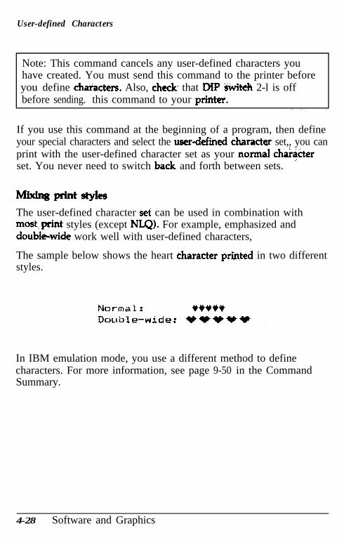
User-defined Characters
Note: This command cancels any user-defined characters youhave created. You must send this command to the printer beforeyou define chaiacters. Also, check, that DW &it& 2-l is offbefore sending. this command to your priiiter.
If you use this command at the beginning of a program, then defineyour special characters and select the userde&d charqcter set,, you canprint with the user-defined character set as your norxqal chiiacterset. You never need to switch b&k, and forth between sets. ..
The user-defined character sei can be used in combination withmost\print styles (except NLQ). For example, emphasized anddoubleiwide work well with user-defined characters,
The sample below shows the heart character printed in two differentstyles.
In IBM emulation mode, you use a different method to definecharacters. For more information, see page 9-50 in the CommandSummary.
4-28 Software and Graphics
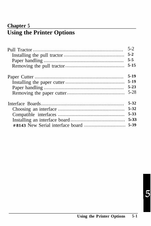
Chapter 5Using the Printer Options
Pull Tractor ............................................................. 5-2Installing the pull tractor ......................................... 5-2
Paper handling ...................................................... 5-5
Removing the pull tractor ........................................ 5-15
Paper Cutter ............................................................ 5-19
Installing the paper cutter ........................................ 5-19
Paper handling ...................................................... 5-23
Removing the paper cutter ....................................... 5-28
Interface Boards........................................................ 5-32Choosing an interface ............................................. 5-32Compatible interfaces ............................................. 5-33
Installing an interface board ..................................... 5-33#8143 New Serial interface board ............................ 5-39
5Using the Printer Options 5-1
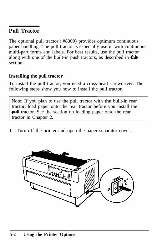
Pull Tractor
The optional pull tractor ( #8309) provides optimum continuouspaper handling. The pull tractor is especially useful with continuousmulti-part forms and labels. For best results, use the pull tractoralong with one of the built-in push tractors, as described in ,thissection.
Installing the pull tractor
To install the pull tractor, you need a cross-head screwdriver. Thefollowing steps show you how to install the pull tractor.
Note: If you plan to use the pull tractor with the built-in reartractor, load paper onto the rear tractor before you install the.pull tractor. See the section on loading paper onto the reartractor in Chapter 2.
1.. Turn off the printer and open the paper separator cover.
5-2 Using the Printer Options

2.
Pull Tractor
Use a cross-head screwdriver to remove the two screws securingthe paper separator to the printer. Then lift the paper separatoroff the printer.
3.. Using the two screws you just removed from the printer’soriginal paper separator, install the paper separator that comeswith the pull tractor.
Using the Printer Options 5-3
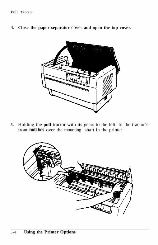
4.
5.
Close the paper separator cover and open the top cover.
Pull Tractor
Holding the pull tractor with its gears to the left, fit the tractor’sfront notches over the mounting shaft in the printer.
5-4 Using the Printer Options
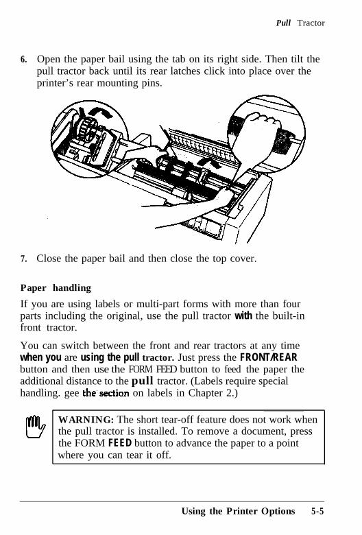
Pull Tractor
6. Open the paper bail using the tab on its right side. Then tilt thepull tractor back until its rear latches click into place over theprinter’s rear mounting pins.
7. Close the paper bail and then close the top cover.
Paper handling
If you are using labels or multi-part forms with more than fourparts including the original, use the pull tractor with the built-infront tractor.
You can switch between the front and rear tractors at any timewhen you are using the pull tractor. Just press the FRONT/REARbutton and then use the FORM FEED button to feed the paper theadditional distance to the pull tractor. (Labels require specialhandling. gee the’section on labels in Chapter 2.)
WARNING: The short tear-off feature does not work whenthe pull tractor is installed. To remove a document, pressthe FORM FEED button to advance the paper to a pointwhere you can tear it off.
Using the Printer Options 5-5
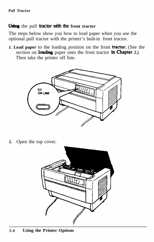
Pull Tractor
Us@ the pull tractor with the front tractor
The steps below show you how to load paper when you use theoptional pull tractor with the printer’s built-in front tractor.
1. Load paper to the loading position on the front t+tor. (See thesection on iw paper onto the front tractor &Chapter 2.)Then take the printer off line.
2. Open the top cover.
5-6 Using the Printer Options
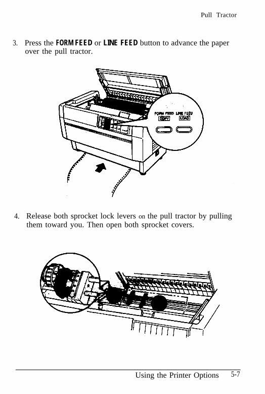
Pull Tractor
3.
4.
Press the FORM FEED or LINE FEED button to advance the paperover the pull tractor.
FQMFEED WEFEE
Release both sprocket lock levers on the pull tractor by pullingthem toward you. Then open both sprocket covers.
Using the Printer Options 5-7
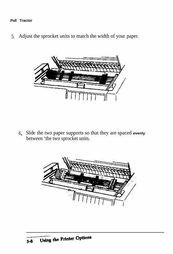
Pull Tractor
5. Adjust the sprocket units to match the width of your paper.
6.’
Slide the two paper supports so that they are spaced evenly
between ‘the two sprocket units.
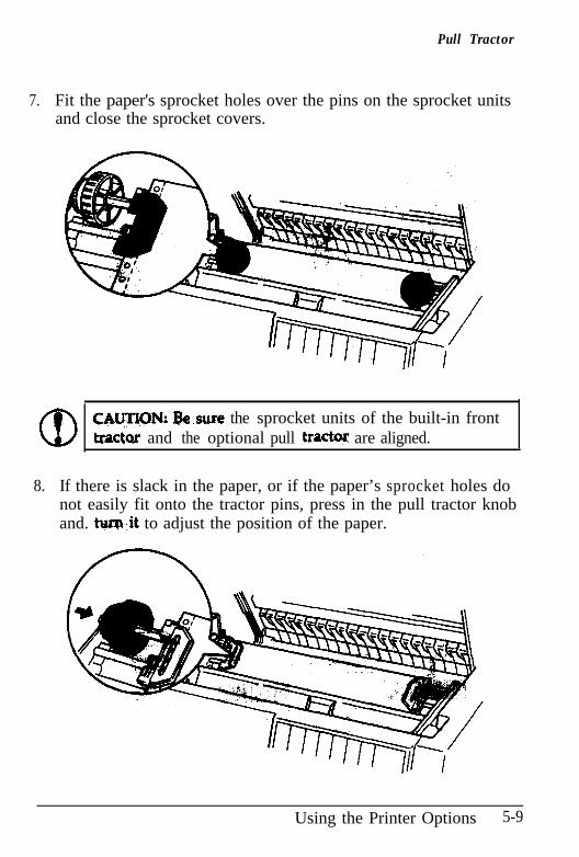
Pull Tractor
7. Fit the paper's sprocket holes over the pins on the sprocket unitsand close the sprocket covers.
CAWN: Qe.sure the sprocket units of the built-in fronttractor’ and the optional pull trac@ are aligned.
8. If there is slack in the paper, or if the paper’s sprocket holes donot easily fit onto the tractor pins, press in the pull tractor knoband. tw~.it to adjust the position of the paper.
Using the Printer Options 5-9
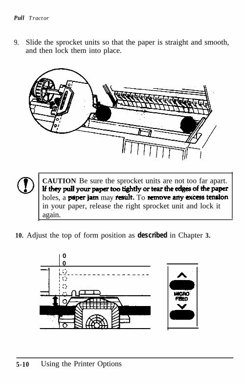
Pull Tractor
9. Slide the sprocket units so that the paper is straight and smooth,and then lock them into place.
CAUTION Be sure the sprocket units are not too far apart.Ifthcppullyourpaper~tightlyorttar~e~ofthepaperholes, a paperjam may tit. To wmove anyextiess ten&onin your paper, release the right sprocket unit and lock itagain.
10. Adjust the top of form position as described in Chapter 3.
00
5-10 Using the Printer Options
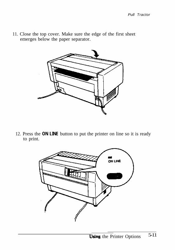
Pull Tractor
11. Close the top cover. Make sure the edge of the first sheetemerges below the paper separator.
12. Press the ON LINE button to put the printer on line so it is readyto print.
U the Printer Options 5-11
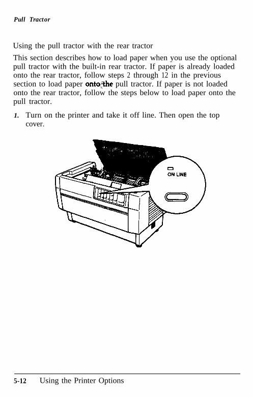
Pull Tractor
Using the pull tractor with the rear tractor
This section describes how to load paper when you use the optionalpull tractor with the built-in rear tractor. If paper is already loadedonto the rear tractor, follow steps 2 through 12 in the previoussection to load paper ontqjthe pull tractor. If paper is not loadedonto the rear tractor, follow the steps below to load paper onto thepull tractor.
1. Turn on the printer and take it off line. Then open the topcover.
5-12 Using the Printer Options
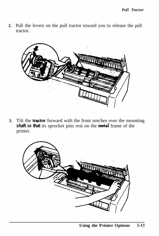
2.
3.
Pull Tractor
Pull the levers on the pull tractor toward you to release the pulltractor.
Tilt the trqctor forward with the front notches over the mountingshaft so that its sprocket pins rest on the meta! frame of theprinter.
Using the Printer Options 5-13
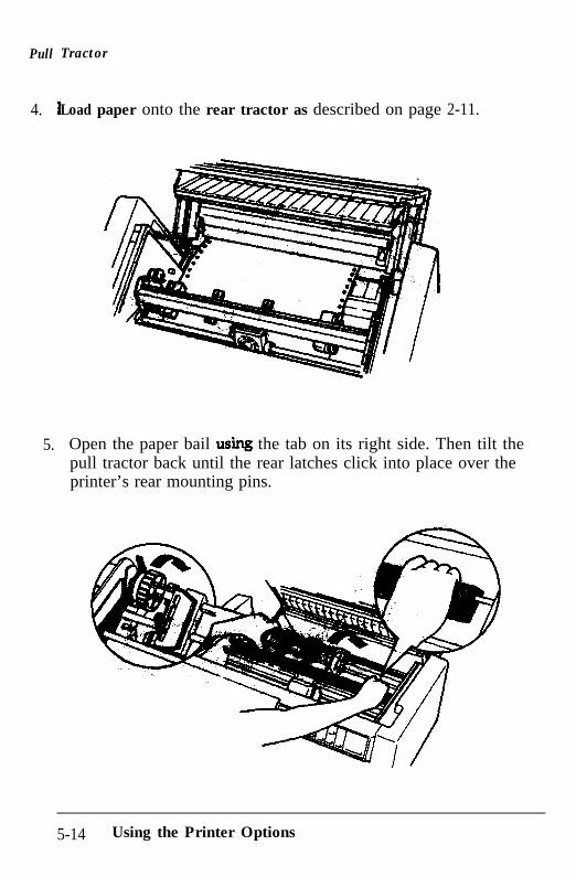
Pull
4.
5.
Tractor
Load paper onto the rear tractor as described on page 2-11.
Open the paper bail usiq the tab on its right side. Then tilt thepull tractor back until the rear latches click into place over theprinter’s rear mounting pins.
5-14 Using the Printer Options
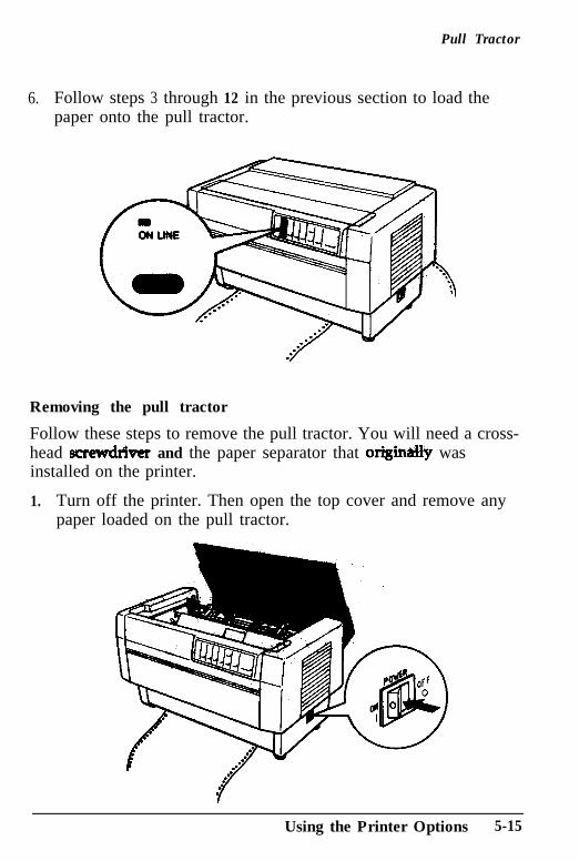
Pull Tractor
6. Follow steps 3 through 12 in the previous section to load thepaper onto the pull tractor.
Removing the pull tractor
Follow these steps to remove the pull tractor. You will need a cross-head screwdrkr and the paper separator that origin&Ily wasinstalled on the printer.
1. Turn off the printer. Then open the top cover and remove anypaper loaded on the pull tractor.
Using the Printer Options 5-15
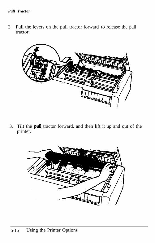
Pull Tractor
2.. Pull the levers on the pull tractor forward to release the pulltractor.
3.. Tilt the p.uJl tractor forward, and then lift it up and out of theprinter.
5-16 Using the Printer Options
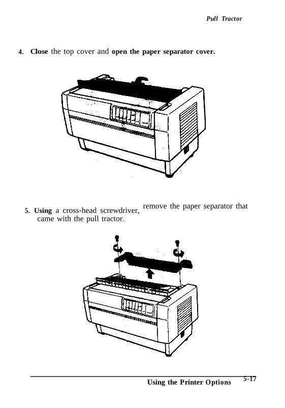
Pull Tractor
4. Close the top cover and open the paper separator cover.
5. Using a cross-head screwdriver, remove the paper separator that
came with the pull tractor.
Using the Printer Options 5-17
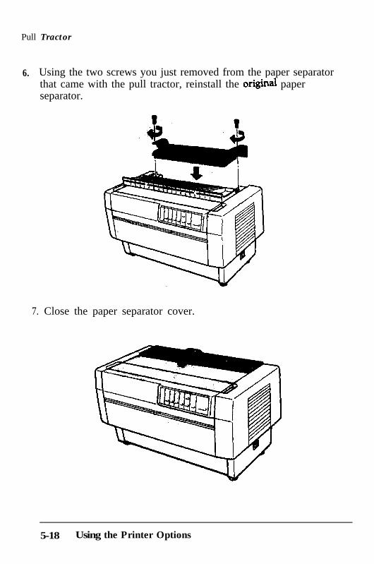
Pull Tractor
6. Using the two screws you just removed from the paper separator that came with the pull tractor, reinstall the ongmal paperseparator.
7. Close the paper separator cover.
5-18 Using the Printer Options
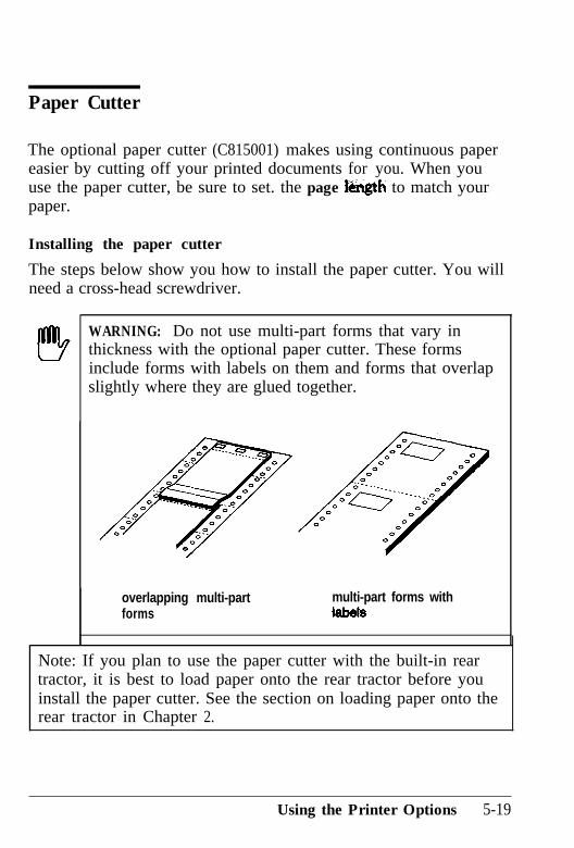
Paper Cutter
The optional paper cutter (C815001) makes using continuous papereasier by cutting off your printed documents for you. When youuse the paper cutter, be sure to set. the page l&ngth to match yourpaper.
Installing the paper cutter
The steps below show you how to install the paper cutter. You willneed a cross-head screwdriver.
WARNING: Do not use multi-part forms that vary inthickness with the optional paper cutter. These formsinclude forms with labels on them and forms that overlapslightly where they are glued together.
overlapping multi-part multi-part forms withforms ISbdS
Note: If you plan to use the paper cutter with the built-in reartractor, it is best to load paper onto the rear tractor before youinstall the paper cutter. See the section on loading paper onto therear tractor in Chapter 2.
Using the Printer Options 5-19
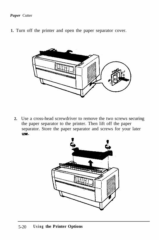
Paper Cutter
1. Turn off the printer and open the paper separator cover.
2. Use a cross-head screwdriver to remove the two screws securingthe paper separator to the printer. Then lift off the paperseparator. Store the paper separator and screws for your laterU%e.
5-20 U s i n g the Printer Options
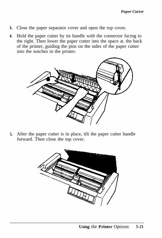
Paper Cutter
3.
4.
5.
Close the paper separator cover and open the top cover.
Hold the paper cutter by its handle with the connector facing tothe right. Then lower the paper cutter into the space at. the backof the printer, guiding the pins on the sides of the paper cutterinto the notches in the printer.
After the paper cutter is in place, tilt the paper cutter handleforward. Then close the top cover.
Using the Printer Options 5-21
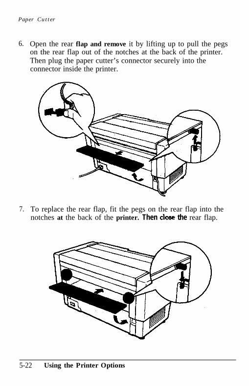
Paper Cutter
6.. Open the rear flap and remove it by lifting up to pull the pegson the rear flap out of the notches at the back of the printer.Then plug the paper cutter’s connector securely into theconnector inside the printer.
7.. To replace the rear flap, fit the pegs on the rear flap into thenotches at the back of the printer. Then dose the rear flap.
5-22 Using the Printer Options
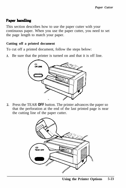
Paper Cutter
This section describes how to use the paper cutter with yourcontinuous paper. When you use the paper cutter, you need to setthe page length to match your paper.
Cutting off a printed document
To cut off a printed document, follow the steps below:
1.. Be sure that the printer is turned on and that it is off line.
2. Press the TEAR OFF button. The printer advances the paper sothat the perforation at the end of the last printed page is nearthe cutting line of the paper cutter.
Using the Printer Options 5-23
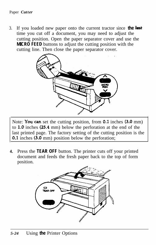
Paper Cutter
3. If you loaded new paper onto the current tractor since the hosttime you cut off a document, you may need to adjust thecutting position. Open the paper separator cover and use theMICRO FEED buttons to adjust the cutting position with thecutting line. Then close the paper separator cover.
Note: You,can set the cutting position, from 0.1 inches (3.0 mm)to 1.0 inches (25.4 mm) below the perforation at the end of thelast printed page. The factory setting of the cutting position is the0.1 inches (3.0 mm) position below the perforation;
4. Press the TEAR OFF button. The printer cuts off your printeddocument and feeds the fresh paper back to the top of formposition.
5-24 Using the Printer Options
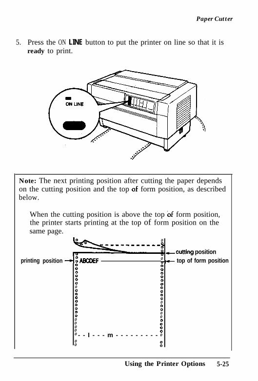
Paper Cutter
5.. Press the ON LINE button to put the printer on line so that it isready to print.
Note: The next printing position after cutting the paper dependson the cutting position and the top qf form position, as describedbelow.
When the cutting position is above the top of form position,the printer starts printing at the top of form position on thesame page.
printing position
0
-cutting position-aBcDEF 0=d- top of form position
x x:: :0” :0
: :
: :0
: :: 0
000 0”00 :0 - - I - - - m - - - - - - - - - 0
00 :
Using the Printer Options 5-25
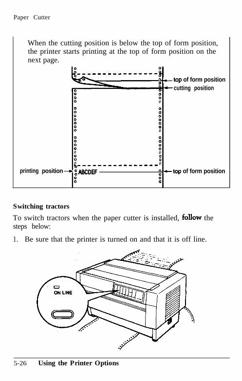
Paper Cutter
When the cutting position is below the top of form position,the printer starts printing at the top of form position on thenext page.
printing
n0-top of form position
cutting position: :: 0
: : 0: :: :: 0
8 : 0: :0 0
: :0 0------------m-e-
position - i WWF G +-top of form position
: 8
Switching tractors
To switch tractors when the paper cutter is installed, fallow thesteps below:
1. Be sure that the printer is turned on and that it is off line.
5-26 Using the Printer Options
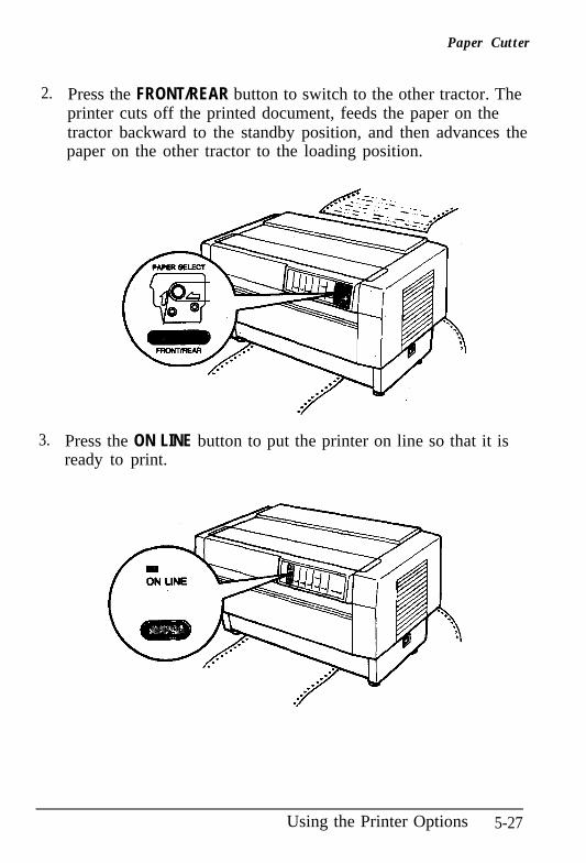
2.
3.
Paper Cutter
Press the FRONT/REAR button to switch to the other tractor. Theprinter cuts off the printed document, feeds the paper on thetractor backward to the standby position, and then advances thepaper on the other tractor to the loading position.
Press the ON LINE button to put the printer on line so that it isready to print.
Using the Printer Options 5-27
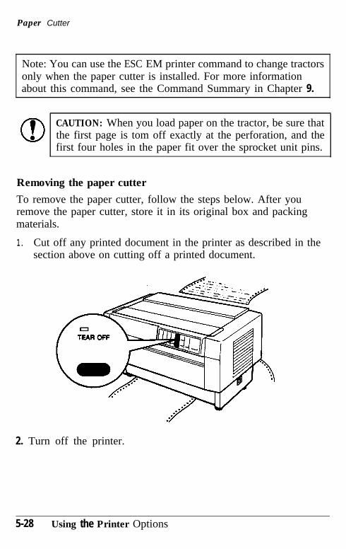
Paper Cutter
Note: You can use the ESC EM printer command to change tractorsonly when the paper cutter is installed. For more informationabout this command, see the Command Summary in Chapter 9.
CAUTION: When you load paper on the tractor, be sure thatthe first page is tom off exactly at the perforation, and thefirst four holes in the paper fit over the sprocket unit pins.
Removing the paper cutter
To remove the paper cutter, follow the steps below. After youremove the paper cutter, store it in its original box and packingmaterials.
1. Cut off any printed document in the printer as described in thesection above on cutting off a printed document.
2. Turn off the printer.
5-28 Using the Printer Options
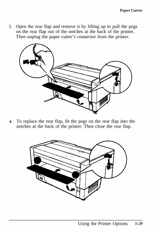
Paper Cutter
3. Open the rear flap and remove it by lifting up to pull the pegson the rear flap out of the notches at the back of the printer.Then unplug the paper cutter’s connector from the printer.
4.. To replace the rear flap, fit the pegs on the rear flap into thenotches at the back of the printer. Then close the rear flap.
Using the Printer Options 5-29
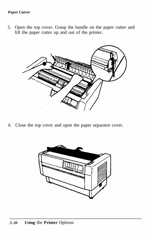
Paper Cutter
5.. Open the top cover. Grasp the handle on the paper cutter andlift the paper cutter up and out of the printer.
6.. Close the top cover and open the paper separator cover.
5-30 Using the Printer Options
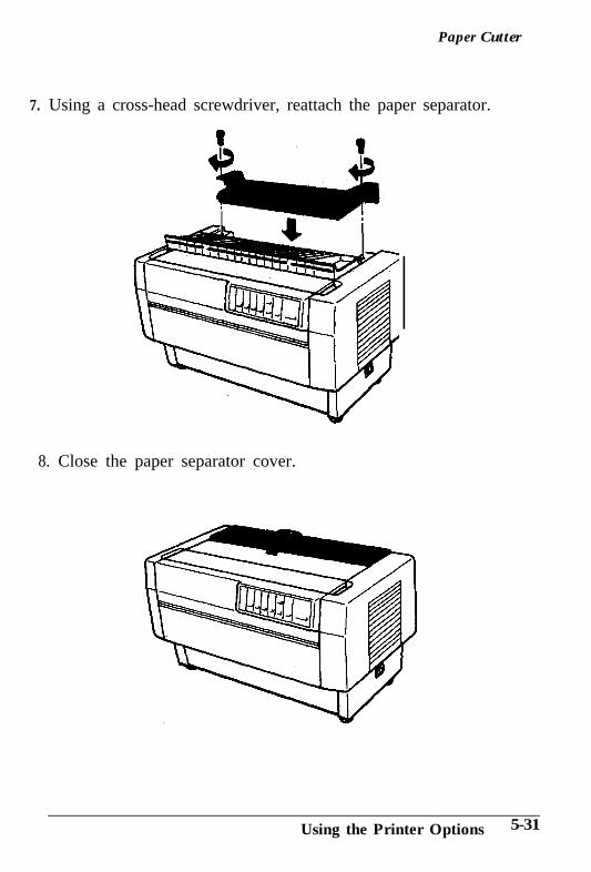
Paper Cutter
7. Using a cross-head screwdriver, reattach the paper separator.
8. Close the paper separator cover.
Using the Printer Options 5-31
Interface Boards
You can use optional interface boards to supplement your printer’sbuilt-in serial and parallel interfaces. If youdon’t know whetheryou need an optionalkterfac,e or if you want to know more aboutinterfaces, contact your Epson dealer,
Choosing an interface
Optional interface boards can be divided into three main categories:
IEEE-488 interfaces that provide standardized connections,trouble-free operation, and the ability to connect computers,printers, and other devices on the same line so that they canshare data freely.
Coax and twinax interfaces that connect directly to the printerand communicate with qn IBM minicomputer or mainframe viacoax or twinax protoco1. These interfaces allow you to useEpson printers as local IBM printers without adding any othercircuitry or components.
Serial interfaces, which are required only if you need aninterface that conforms to the Current Loop standard instead ofRS-232C or that provides X-on$#Gff data communicationsprotocol.
5-32 Using the Printer Options
Interface Boards
Compatible interfaces
The following table lists Epson interfaces that are compatible withthe DFX-8000. Some of these interfaces may not be available inyour country or region and some may be no longer available.
Number
#8143#8148#8165
Name
New Serial interface board’Intelligent serial interface boardIntelligent IEEE-488 interface boardCoax interface boardTwinax interface board
l For more information on the New Serial interface (#8143), see page 5-39.
All Epson interface boards have the Epson name on them. If there isan identification code on the board, it should be one of the four-digit numbers in the table above.
Installing an intirface board
The following steps explain how to install an optional interfaceboard. Before you install an interface board, set the DIP switches orjumpers on the board according to the instructions in yourcomputer and interface board manuals.
Note: Before you install an interface board, be sure your printer’sDIP switches are set for use with a parallel interface, even if youare installing a serial interface board. see! the section on setting
the DIP switches in Chapter 3.
Using the Printer Options 5-33
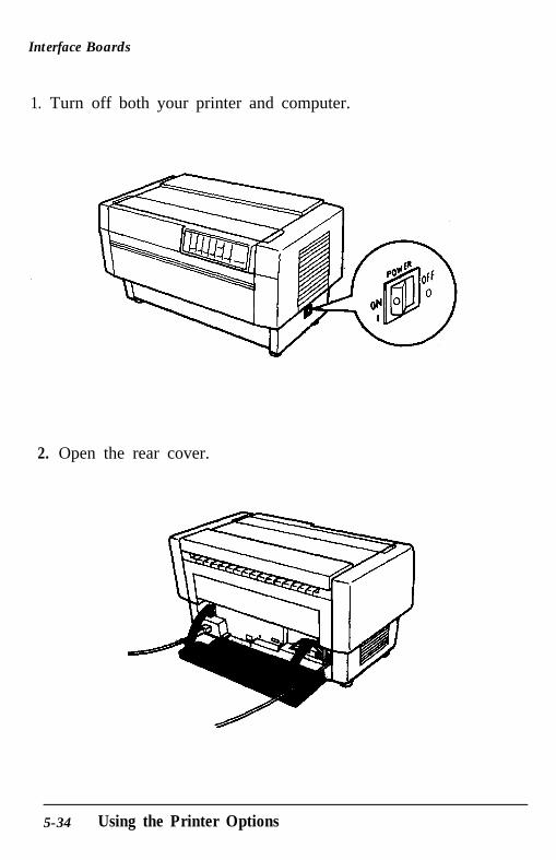
Interface Boards
1. Turn off both your printer and computer.
2. Open the rear cover.
5-34 Using the Printer Options
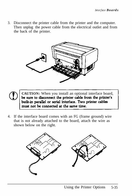
I n t e r f a c e Boards
3.. Disconnect the printer cable from the printer and the computer.Then unplug the power cable from the electrical outlet and fromthe back of the printer.
CAUTION: When you install an optional interface board,
4.. If the interface board comes with an FG (frame ground) wirethat is not already attached to the board, attach the wire asshown below on the right.
Using the Printer Options 5-35
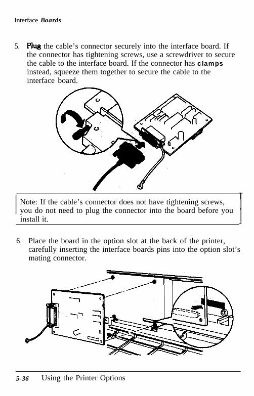
Interface Boards
5. Plug the cable’s connector securely into the interface board. Ifthe connector has tightening screws, use a screwdriver to securethe cable to the interface board. If the connector has clampsinstead, squeeze them together to secure the cable to theinterface board.
Note: If the cable’s connector does not have tightening screws,you do not need to plug the connector into the board before youinstall it.
6.. Place the board in the option slot at the back of the printer,carefully inserting the interface boards pins into the option slot’smating connector.
5-36 Using the Printer Options
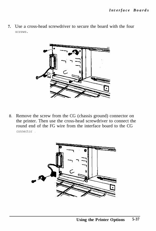
7.
8.
I n t e r f a c e B o a r d s
Use a cross-head screwdriver to secure the board with the fourscrews.
Remove the screw from the CG (chassis ground) connector onthe printer. Then use the cross-head screwdriver to connect theround end of the FG wire from the interface board to the CGconnector .
Using the Printer Options 5-37
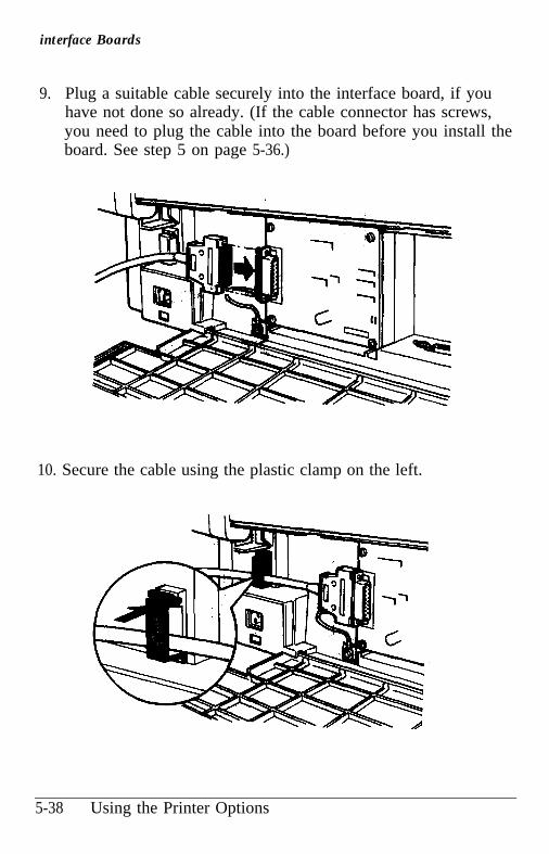
interface Boards
9.. Plug a suitable cable securely into the interface board, if youhave not done so already. (If the cable connector has screws,you need to plug the cable into the board before you install theboard. See step 5 on page 5-36.)
10. Secure the cable using the plastic clamp on the left.
5-38 Using the Printer Options
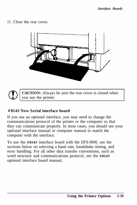
Interface Boards
11. Close the rear cover.
CAUTION: Always be sure the rear cover is closed whenyou use the printer.
#8143 New Serial interface board
If you use an optional interface, you may need to change thecommunications protocol of the printer or the computer so thatthey can communicate properly. In most cases, you should see youroptional interface manual or computer manual to match thecomputer with the interface.
To use the #8143 interface board with the DFX-8000, see thesections below on selecting a baud rate, handshake timing, anderror handling. For all other data transfer conventions, such asword structure and communications protocol, see the #8143optional interface board manual,
Using the Printer Options 5-39
interface Boards
Selecting a baud rate
The range of baud rate settings for the #8143 interface depends onwhether your printer’s input buffer is on or off.
You can select baud rates from 75 to 19,200 bps (bits per second).When you set the baud rate, use the bit rate selection table forprinters with buffers in the #8143 interface manual.
Handshake timing
When the vacant area for data in the input buffer &ps to 512bytes, the printer outputs an$O~ code or sets the DTR flag to '1"(MARK) to indicate that it ¬ raceive data.
When the vacant area for data in the buffer increases to 784 bytes,the printer outputs an X-ON code or sets the DTR flag to ‘0”(SPACE) to indicate that it is ready to receive data.
Error handling
When the printer detects a parity error, it prints an asterisk ( * ) .The printer ignores all other errors, including framing and overrunerrors.
5-40 Using the Printer Options
Chapter 6Maintenance
Cleaning the Printer . . . . . . . . . . . . . . . . . . . . . . . . . . . . . . . . . . . . . . . . . . . . . . . . . . 6-21
Replacing the Ribbon . . . . . . . . . . . . . . . . . . . . . . . . . . . . . . . . . . . . . . . . . . . . . . . . .6-4
10Transporting the Printer ,..............,............................. 6-9
Maintenance 6-1
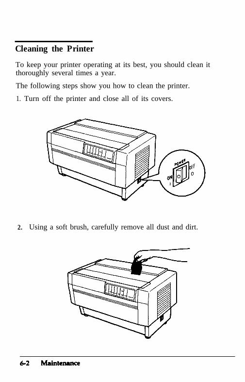
Cleaning the Printer
To keep your printer operating at its best, you should clean itthoroughly several times a year.
The following steps show you how to clean the printer.
1. Turn off the printer and close all of its covers.
2. Using a soft brush, carefully remove all dust and dirt.
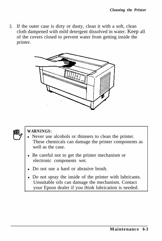
Cleaning the Printer
3. If the outer case is dirty or dusty, clean it with a soft, cleancloth dampened with mild detergent dissolved in water. Keep allof the covers closed to prevent water from getting inside theprinter.
WARNINGS:l Never use alcohols or thinners to clean the printer.
These chemicals can damage the printer components aswell as the case.
l Be careful not to get the printer mechanism orelectronic components wet.
l Do not use a hard or abrasive brush.
l Do not spray the inside of the printer with lubricants.Unsuitable oils can damage the mechanism. Contactyour Epson dealer if you think lubrication is needed.
Maintenance 6-3
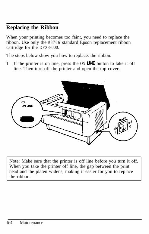
Replacing the Ribbon
When your printing becomes too faint, you need to replace theribbon. Use only the # 8 7 6 6 standard Epson replacement ribboncartridge for the DFX-8000.
The steps below show you how to replace. the ribbon.
1.. If the printer is on line, press the ON Ll!lE button to take it offline. Then turn off the printer and open the top cover.
Note: Make sure that the printer is off line before you turn it off.When you take the printer off line, the gap between the printhead and the platen widens, making it easier for you to replacethe ribbon.
6-4 Maintenance
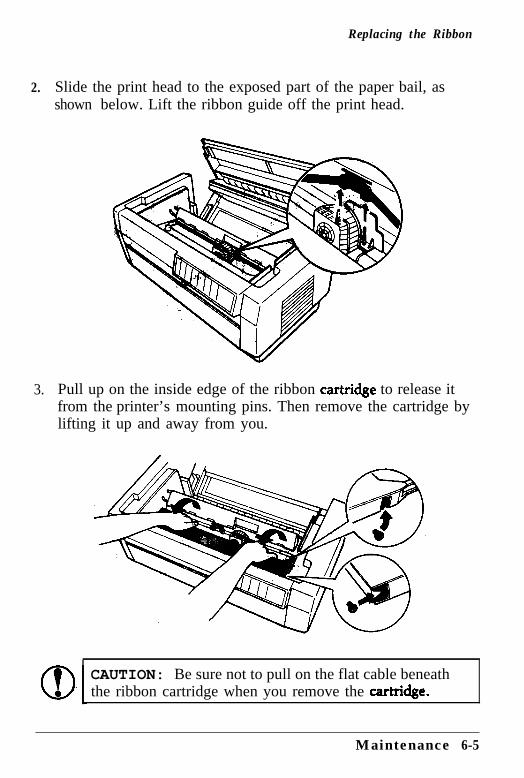
Replacing the Ribbon
2.
3.
Slide the print head to the exposed part of the paper bail, asshown below. Lift the ribbon guide off the print head.
Pull up on the inside edge of the ribbon cartiidge to release itfrom the printer’s mounting pins. Then remove the cartridge bylifting it up and away from you.
CAUTION: Be sure not to pull on the flat cable beneaththe ribbon cartridge when you remove the catidge.
Maintenance 6-5
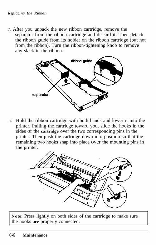
Replacing the Ribbon
4. After you unpack the new ribbon cartridge, remove theseparator from the ribbon cartridge and discard it. Then detachthe ribbon guide from its holder on the ribbon cartridge (but notfrom the ribbon). Turn the ribbon-tightening knob to removeany slack in the ribbon.
5.. Hold the ribbon cartridge with both hands and lower it into theprinter. Pulling the cartridge toward you, slide the hooks in thesides of the cartridge over the two corresponding pins in theprinter. Then push the cartridge down into position so that theremaining two hooks snap into place over the mounting pins inthe printer.
Note: Press lightly on both sides of the cartridge to make surethe hooks are properly connected.
6-6 Maintenance
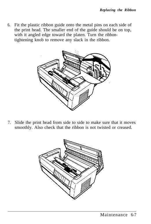
Replacing the Ribbon
6. Fit the plastic ribbon guide onto the metal pins on each side ofthe print head. The smaller end of the guide should be on top,with it angled edge toward the platen. Turn the ribbon-tightening knob to remove any slack in the ribbon.
7. Slide the print head from side to side to make sure that it movessmoothly. Also check that the ribbon is not twisted or creased.
Maintenance 6-7
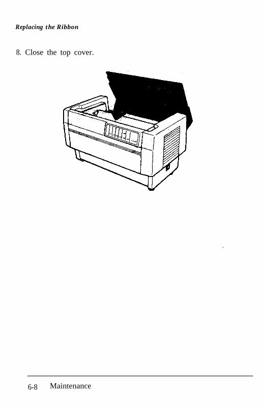
Replacing the Ribbon
8. Close the top cover.
6-8 Maintenance
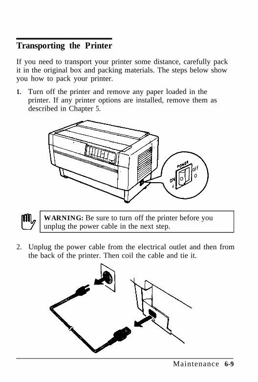
Transporting the Printer
If you need to transport your printer some distance, carefully packit in the original box and packing materials. The steps below showyou how to pack your printer.
1. Turn off the printer and remove any paper loaded in theprinter. If any printer options are installed, remove them asdescribed in Chapter 5.
I!!!3 WARNING: Be sure to turn off the printer before youunplug the power cable in the next step.
2.. Unplug the power cable from the electrical outlet and then fromthe back of the printer. Then coil the cable and tie it.
Maintenance 6-9
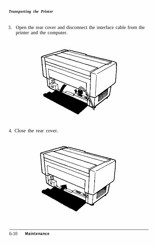
Transporting the Printer
3.. Open the rear cover and disconnect the interface cable from theprinter and the computer.
4. Close the rear cover.
6-10 Maintenance
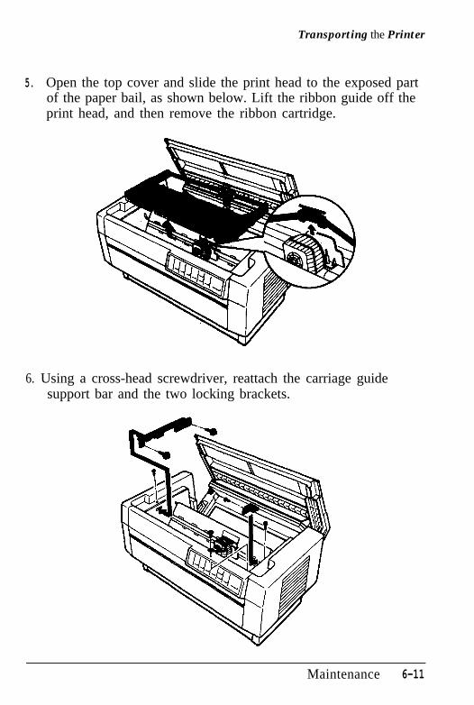
Transporting the Printer
5. Open the top cover and slide the print head to the exposed partof the paper bail, as shown below. Lift the ribbon guide off theprint head, and then remove the ribbon cartridge.
6. Using a cross-head screwdriver, reattach the carriage guidesupport bar and the two locking brackets.
Maintenance 6-11
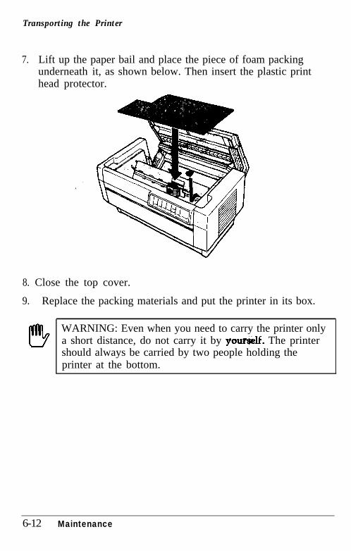
Transporting the Printer
7. Lift up the paper bail and place the piece of foam packingunderneath it, as shown below. Then insert the plastic printhead protector.
8. Close the top cover.
9.. Replace the packing materials and put the printer in its box.
WARNING: Even when you need to carry the printer onlya short distance, do not carry it by your&. The printershould always be carried by two people holding theprinter at the bottom.
6-12 Maintenance

Chapter 7Troubleshooting
Problems and Solutions .............................................. 7-2
Power Supply .......................................................... 7-3
Printing................................................................... 7-4
Paper Handling ........................................................ 7-13
Options ................................................................... 7-18
Troubleshooting 7-1
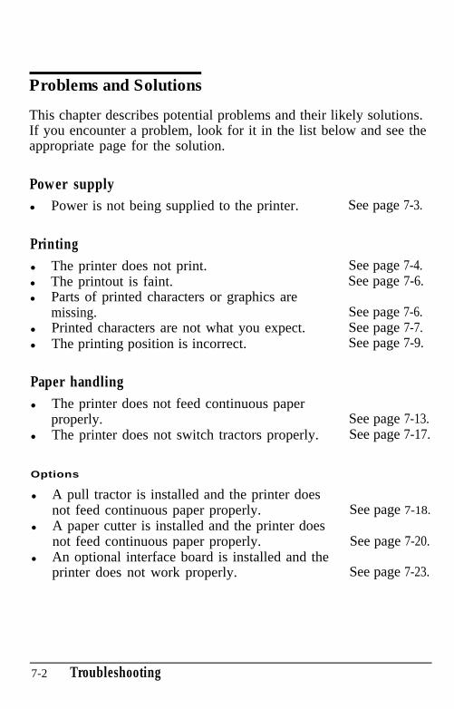
Problems and Solutions
This chapter describes potential problems and their likely solutions.If you encounter a problem, look for it in the list below and see theappropriate page for the solution.
Power supplyl Power is not being supplied to the printer.
Printingl The printer does not print.l The printout is faint.l Parts of printed characters or graphics are
missing.l Printed characters are not what you expect.l The printing position is incorrect.
Paper handlingl The printer does not feed continuous paper
properly.l The printer does not switch tractors properly.
Options
l A pull tractor is installed and the printer doesnot feed continuous paper properly.
l A paper cutter is installed and the printer doesnot feed continuous paper properly.
l An optional interface board is installed and theprinter does not work properly.
See page 7-3.
See page 7-4.See page 7-6.
See page 7-6.See page 7-7.See page 7-9.
See page 7-13.See page 7-17.
See page 7-18.
See page 7-20.
See page 7-23.
7-2 Troubleshooting
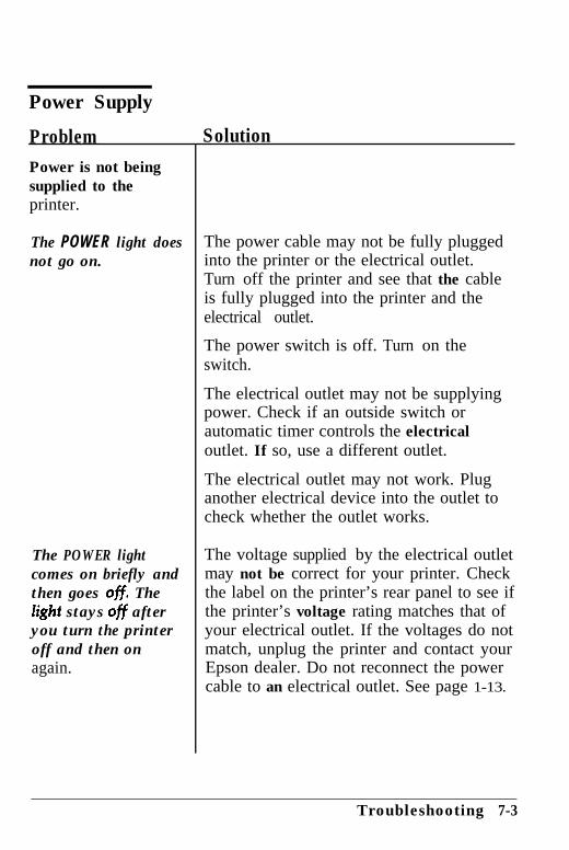
Power Supply
Problem Solution
Power is not beingsupplied to theprinter.
The POWER light doesnot go on.
The POWER lightcomes on briefly andthen goes 0%. TheZight stays ofi afteryou turn the printeroff and then onagain.
The power cable may not be fully pluggedinto the printer or the electrical outlet.Turn off the printer and see that the cableis fully plugged into the printer and theelectrical outlet.
The power switch is off. Turn on theswitch.
The electrical outlet may not be supplyingpower. Check if an outside switch orautomatic timer controls the electricaloutlet. If so, use a different outlet.
The electrical outlet may not work. Pluganother electrical device into the outlet tocheck whether the outlet works.
The voltage supplied by the electrical outletmay not be correct for your printer. Checkthe label on the printer’s rear panel to see ifthe printer’s voltage rating matches that ofyour electrical outlet. If the voltages do notmatch, unplug the printer and contact yourEpson dealer. Do not reconnect the powercable to an electrical outlet. See page 1-13.
Troubleshooting 7-3
Printing
You can solve many printing problems, including problems w%h linespacing and margins, by changing your application program’s settings.When you encounter a printing problem, check your softwaresettings first. If this does not work, check the printer’s D I P switchsettings next.
Problem SolutionThe printer does notprint.
The ON LINE light is0%.
The ON LINE light ison.
The printer may be off line. If so, it cannotreceive and print data. Press the ON LINEbutton. The ON LINE light should go on.See page 3-3.
Your software may not be set up correctlyfor the printer. Check your program’sprinter settings and make any necessarychanges. See page l-36.
The interface cable may be loose. Makesure the printer is connected securely to thecomputer. If you are using a parallelinterface, secure the connector with thewire retaining clips. If you are using aserial interface with a cable connector thathas screws, secure the cable connector usingthe screws. See page l-26.
You may not be using the correct interfacecable. Make sure your interface cable meetsthe printer and the computer specifications.See page 8-11.
7-4 Troubleshooting
Printing
Problem Solution
The PAPER OUT lightis on.
The printer beepsfour times and stopsprinting and theON LINE light goes off,
The printer soundslike it is printing, butnothing is printed.
The printer makes LJstrange noise, beepsseveral times, andstops printing.
The ON LINE light isflickering and theprinter does notprint.
The printer’s interface DIP switch settingsmay not be correct. Check DIP switches2-5, 2-6, 2-7, and 2-8, and reset them ifnecessary. See page 3-13.
The printer may be out of paper. If so,load paper. Be sure the paper is properlyloaded onto the printer’s sprocket pins. Seepages 2-4 and 2-11.
The top cover may be open. To resumeprinting, close the top cover and press theON LINE button.
The ribbon cartridge may not be installedproperly. Turn off the printer, reinstall theribbon cartridge, and take up any slack inthe ribbon. See page l-9.
The ribbon may be worn. Replace theribbon cartridge. See page 6-4.
Your printer is not working properly. Turnoff the printer and check for paper jams orother problems. Make sure that all protectivematerials are removed. Then turn on theprinter. If the printer still does not printcorrectly, contact your Epson dealer.
The print head is overheated. Wait severalminutes until the printer head cools.Printing resumes when the head cools.
Troubleshooting 7-5
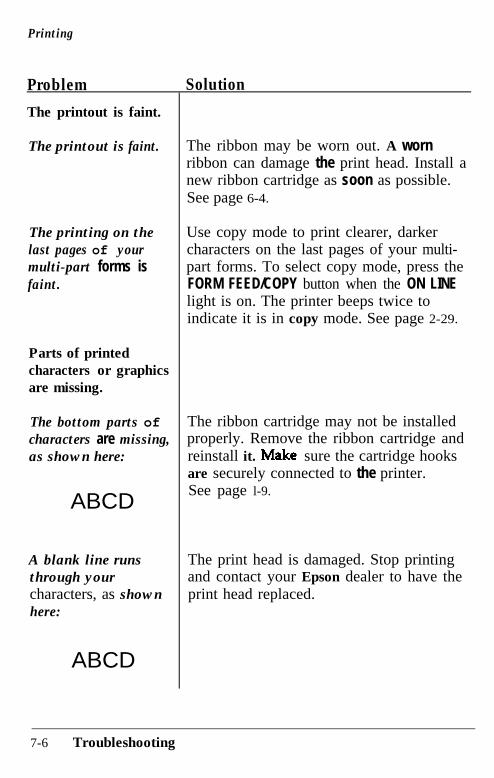
Printing
Problem Solution
The printout is faint.
The printout is faint.
The printing on thelast pages of yourmulti-part forms isfaint.
Parts of printedcharacters or graphicsare missing.
The bottom parts ofcharacters are missing,as shown here:
ABCD
A blank line runsthrough yourcharacters, as shownhere:
ABCD
The ribbon may be worn out. A wornribbon can damage the print head. Install anew ribbon cartridge as soon as possible.See page 6-4.
Use copy mode to print clearer, darkercharacters on the last pages of your multi-part forms. To select copy mode, press theFORM FEED/COPY button when the ON LINElight is on. The printer beeps twice toindicate it is in copy mode. See page 2-29.
The ribbon cartridge may not be installedproperly. Remove the ribbon cartridge andreinstall it. Make’ sure the cartridge hooksare securely connected to the printer.See page l-9.
The print head is damaged. Stop printingand contact your Epson dealer to have theprint head replaced.
7-6 Troubleshooting
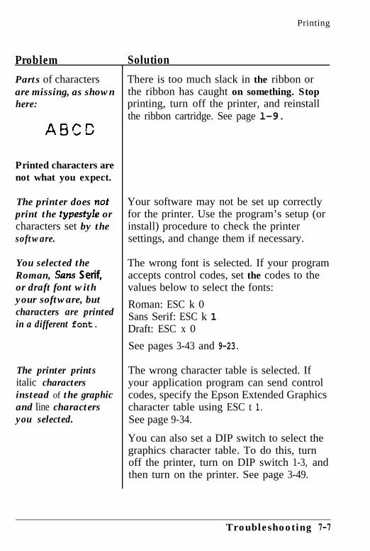
Printing
Problem Solution
Parts of charactersare missing, as shownhere:
Printed characters arenot what you expect.
The printer does nof Your software may not be set up correctlyprint the typesty2e or for the printer. Use the program’s setup (orcharacters set by the install) procedure to check the printersoftware. settings, and change them if necessary.
You selected theRoman, Suns Serif,or draft font withyour software, butcharacters are printedin a different font.
The wrong font is selected. If your programaccepts control codes, set the codes to thevalues below to select the fonts:
Roman: ESC k 0Sans Serif: ESC k 1Draft: ESC x 0
The printer printsitalic charactersinstead of the graphicand Iine charactersyou selected.
There is too much slack in the ribbon orthe ribbon has caught on something. Stopprinting, turn off the printer, and reinstallthe ribbon cartridge. See page l-9.
See pages 3-43 and 9-23.
The wrong character table is selected. Ifyour application program can send controlcodes, specify the Epson Extended Graphicscharacter table using ESC t 1.See page 9-34.
You can also set a DIP switch to select thegraphics character table. To do this, turnoff the printer, turn on DIP switch 1-3, andthen turn on the printer. See page 3-49.
Troubleshooting 7-7
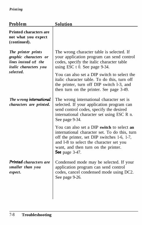
Printing
Problem Solution
Printed characters arenot what you expect(continued).
The printer printsgraphic characters orlines instead of theitalic characters youselected.
The wrong inkmationalcharacters are printed.
P&ted characters aresmaller than youexpect.
The wrong character table is selected. Ifyour application program can send controlcodes, specify the italic character tableusing ESC t 0. See page 9-34.
You can also set a DIP switch to select theitalic character table. To do this, turn offthe printer, turn off DIP switch l-3, andthen turn on the printer. See page 3-49.
The wrong international character set isselected. If your application program cansend control codes, specify the desiredinternational character set using ESC R n.See page 9-34.
You can also set a DIP switch to select aninternational character set. To do this, turnoff the printer, set DIP switches 1-6, 1-7,and l-8 to select the character set youwant, and then turn on the printer.see page 3-47.
Condensed mode may be selected. If yourapplication program can send controlcodes, cancel condensed mode using DC2.See page 9-26.
7-8 Troubleshooting
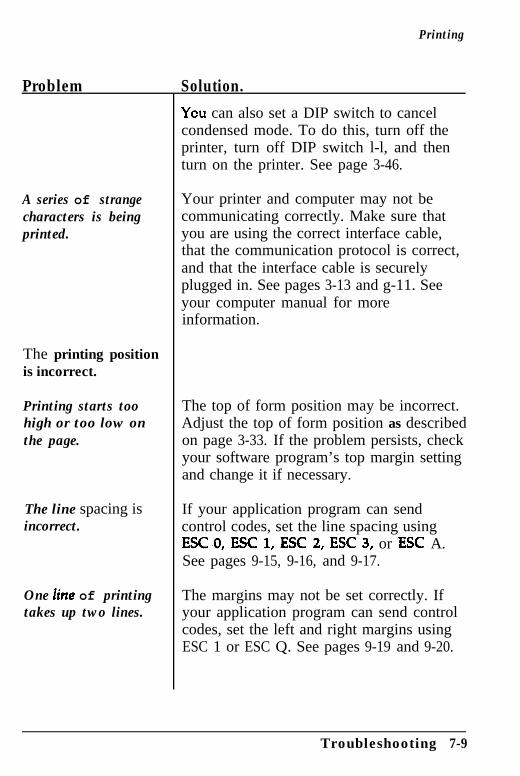
Printing
Problem Solution.
A series of strangecharacters is beingprinted.
The printing positionis incorrect.
Printing starts toohigh or too low onthe page.
The line spacing isincorrect.
One Zinc of printingtakes up two lines.
Ycu can also set a DIP switch to cancelcondensed mode. To do this, turn off theprinter, turn off DIP switch l-l, and thenturn on the printer. See page 3-46.
Your printer and computer may not becommunicating correctly. Make sure thatyou are using the correct interface cable,that the communication protocol is correct,and that the interface cable is securelyplugged in. See pages 3-13 and g-11. Seeyour computer manual for moreinformation.
The top of form position may be incorrect.Adjust the top of form position as describedon page 3-33. If the problem persists, checkyour software program’s top margin settingand change it if necessary.
If your application program can sendcontrol codes, set the line spacing usingESCO, ESC 1, ESC 2, ESC 3, or ESC A.See pages 9-15, 9-16, and 9-17.
The margins may not be set correctly. Ifyour application program can send controlcodes, set the left and right margins usingESC 1 or ESC Q. See pages 9-19 and 9-20.
Troubleshooting 7-9
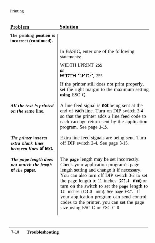
Printing
Problem Solution
The printing position isincorrect (continued).
In BASIC, enter one of the followingstatements:
WIDTH LPRINT 255
LDTH “LPTl:“, 255
If the printer still does not print properly,set the right margin to the maximum settingusing ESC Q.
All the text is printedon the same line.
The printer insertsextra blank linesbetween lines of text.
The page length doesnot match the lengthof the paper.
A line feed signal is not being sent at theend of each line. Turn on DIP switch 2-4so that the printer adds a line feed code toeach carriage return sent by the applicationprogram. See page 3-15.
Extra line feed signals are being sent. Turnoff DIP switch 2-4. See page 3-15.
The page length may be set incorrectly.Check your application program’s pagelength setting and change it if necessary.You can also turn off DIP switch 3-2 to setthe page length to 11 inches (279.4 mm) orturn on the switch to set the page length to12 inches (304.8 mm). See page 3-17. Ifyour application program can send controlcodes to the printer, you can set the pagesize using ESC C or ESC C 0.
7-10 Troubleshooting
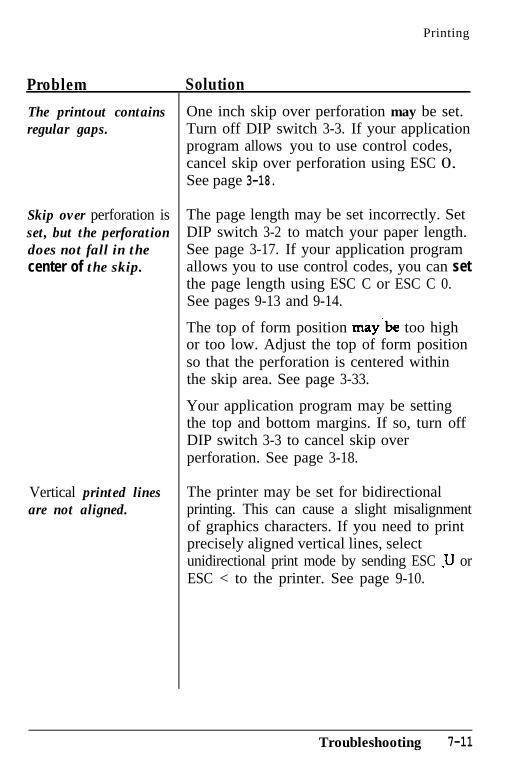
Printing
Problem Solution
The printout containsregular gaps.
Skip over perforation isset, but the perforationdoes not fall in thecenter of the skip.
Vertical printed linesare not aligned.
One inch skip over perforation may be set.Turn off DIP switch 3-3. If your applicationprogram allows you to use control codes,cancel skip over perforation using ESC 0.See page 3-18.
The page length may be set incorrectly. SetDIP switch 3-2 to match your paper length.See page 3-17. If your application programallows you to use control codes, you can setthe page length using ESC C or ESC C 0.See pages 9-13 and 9-14.
The top of form position may‘be too highor too low. Adjust the top of form positionso that the perforation is centered withinthe skip area. See page 3-33.
Your application program may be settingthe top and bottom margins. If so, turn offDIP switch 3-3 to cancel skip overperforation. See page 3-18.
The printer may be set for bidirectionalprinting. This can cause a slight misalignmentof graphics characters. If you need to printprecisely aligned vertical lines, selectunidirectional print mode by sending ESC )I orESC < to the printer. See page 9-10.
Troubleshooting 7-11
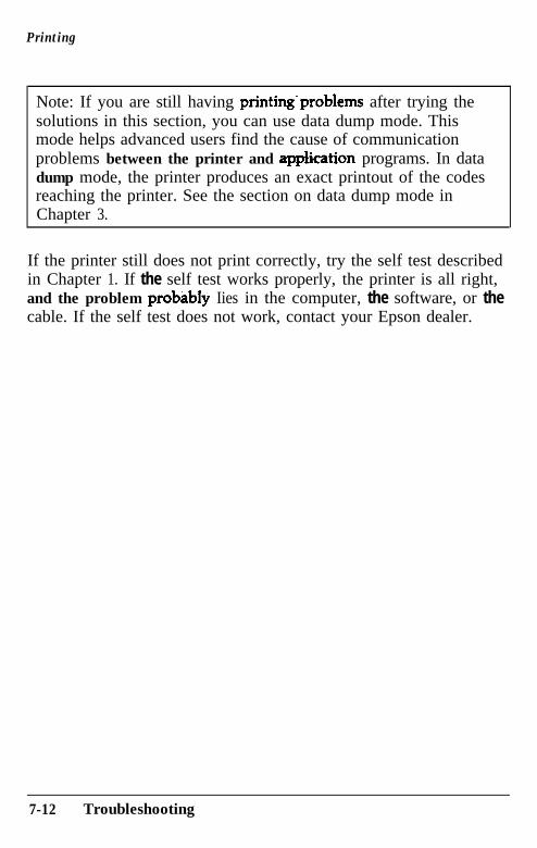
Printing
Note: If you are still having printing’problems after trying thesolutions in this section, you can use data dump mode. Thismode helps advanced users find the cause of communicationproblems between the printer and appkation programs. In datadump mode, the printer produces an exact printout of the codesreaching the printer. See the section on data dump mode inChapter 3.
If the printer still does not print correctly, try the self test describedin Chapter 1. If the self test works properly, the printer is all right,and the problem probabIy Iies in the computer, the software, or thecable. If the self test does not work, contact your Epson dealer.
7-12 Troubleshooting
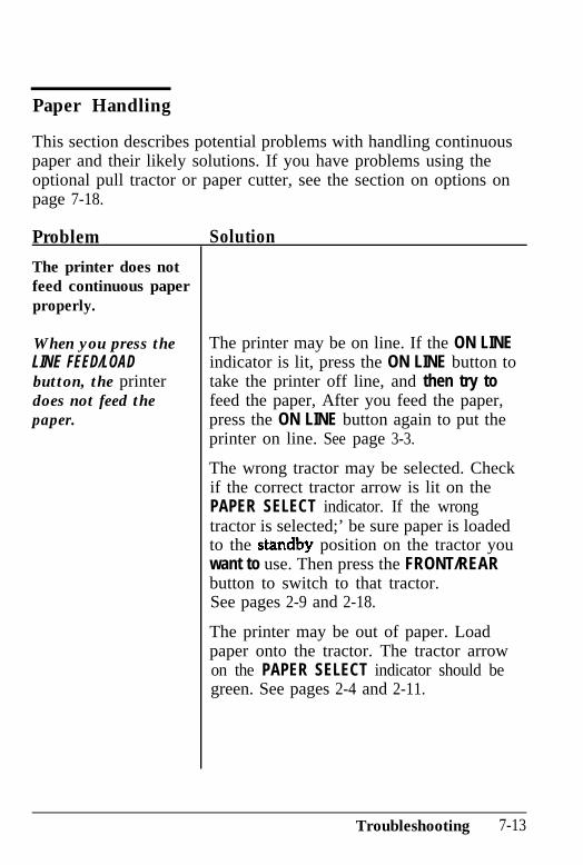
Paper Handling
This section describes potential problems with handling continuouspaper and their likely solutions. If you have problems using theoptional pull tractor or paper cutter, see the section on options onpage 7-18.
Problem Solution
The printer does notfeed continuous paperproperly.
When you press theLINE FEED/LOADbutton, the printerdoes not feed thepaper.
The printer may be on line. If the ON LINEindicator is lit, press the ON LINE button totake the printer off line, and then try tofeed the paper, After you feed the paper,press the ON LINE button again to put theprinter on line. See page 3-3.
The wrong tractor may be selected. Checkif the correct tractor arrow is lit on thePAPER SELECT indicator. If the wrongtractor is selected;’ be sure paper is loadedto the standb position on the tractor youwant to use. Then press the FRONT/REARbutton to switch to that tractor.See pages 2-9 and 2-18.
The printer may be out of paper. Loadpaper onto the tractor. The tractor arrowon the PAPER SELECT indicator should begreen. See pages 2-4 and 2-11.
Troubleshooting 7-13
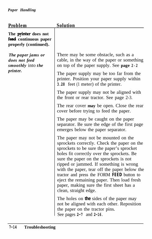
Paper Handling
Problem Solution
The penter does notfed continuous paperproperly (continued).
The paper jams ordoes not feedsmoothly into theprinter.
There may be some obstacle, such as acable, in the way of the paper or somethingon top of the paper supply. See page 2 - 2
The paper supply may be too far from theprinter. Position your paper supply within3.28 feet (1 meter) of the printer.
The paper supply may not be aligned withthe front or rear tractor. See page 2-3.
The rear cover may be open. Close the rearcover before trying to feed the paper.
The paper may be caught on the paperseparator. Be sure the edge of the first pageemerges below the paper separator.
The paper may not be mounted on thesprockets correctly. Check the paper on thesprockets to be sure the paper’s sprocketholes fit correctly over the sprockets. Besure the paper on the sprockets is notripped or jammed. If something is wrongwith the paper, tear off the paper below thetractor and press the FORM FEED button toeject the remaining paper. Then load freshpaper, making sure the first sheet has aclean, straight edge.
The holes on the sides of the paper maynot be aligned with each other. Repositionthe paper on the tractor pins.See pages 2-7 and 2-16.
7-14 Troubleshooting
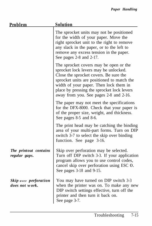
Paper Handling
Problem Solution
The sprocket units may not be positionedfor the width of your paper. Move theright sprocket unit to the right to removeany slack in the paper, or to the left toremove any excess tension in the paper.See pages 2-8 and 2-17.
The sprocket covers may be open or thesprocket lock levers may be unlocked.Close the sprocket covers. Be sure thesprocket units are positioned to match thewidth of your paper. Then lock them inplace by pressing the sprocket lock leversaway from you. See pages 2-8 and 2-16.
The paper may not meet the specificationsfor the DFX-8000. Check that your paper isof the proper size, weight, and thickness.See pages 8-5 and 8-6.
The print head may be catching the bindingarea of your multi-part forms. Turn on DIPswitch 3-7 to select the skip over bindingfunction. See page 3-16.
The printout containsregular gaps.
Skip over perforation may be selected.Turn off DIP switch 3-3. If your applicationprogram allows you to use control codes,cancel skip over perforation using ESC 0.See pages 3-18 and 9-15.
Skip over perforationdoes not work.
You may have turned on DIP switch 3-3when the printer was on. To make any newDIP switch settings effective, turn off theprinter and then turn it back on.See page 3-7.
Troubleshooting 7-15
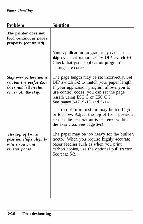
Paper Handling
Problem SolutionThe printer does notfeed continuous paperproperly (continued).
Skip over perforation isset, but the petftirationdoes not fall in thecenter of the skip.
The top of formposition shifts slightlywhen you printseveral pages.
Your application program may cancel the5kip over perforation set by DIP switch 3-3.Check that your application program’ssettings are correct.
The page length may be set incorrectly. SetDIP switch 3-2 to match your paper length.If your application program allows you touse control codes, you can set the pagelength using ESC C or ESC C 0.See pages 3-17, 9-13 and 9-14
The top of form position may be too highor too low. Adjust the top of form positionso that the perforation is centered withinthe skip area. See page 3-33.
The paper may be too heavy for the built-intractor. When you require highly accuratepaper feeding such as when you printcarbon copies, use the optional pull tractor.See page 5-2.
7-16 Troubleshooting
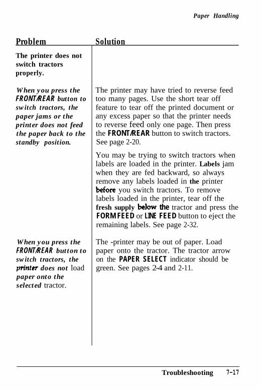
Paper Handling
Problem SolutionThe printer does notswitch tractorsproperly.
When you press the The printer may have tried to reverse feedFRONT/REAR button to too many pages. Use the short tear offswitch tractors, the feature to tear off the printed document orpaper jams or the any excess paper so that the printer needsprinter does not feed to reverse feed only one page. Then pressthe paper back to the the FRONT/REAR button to switch tractors.standby position. See page 2-20.
When you press theFRONT/REAR button toswitch tractors, thepn’nter does not loadpaper onto theselected tractor.
You may be trying to switch tractors whenlabels are loaded in the printer. Labels jamwhen they are fed backward, so alwaysremove any labels loaded in the printerbefQre you switch tractors. To removelabels loaded in the printer, tear off thefresh supply behn~ the tractor and press theFORM FEED or LINE FEED button to eject theremaining labels. See page 2-32.
The -printer may be out of paper. Loadpaper onto the tractor. The tractor arrowon the PAPER SELECT indicator should begreen. See pages 2-4 and 2-11.
Troubleshooting 7-17
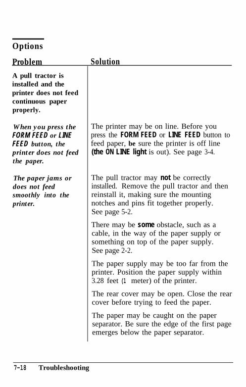
Options
Problem SolutionA pull tractor isinstalled and theprinter does not feedcontinuous paperproperly.
When you press theFORM FEED or LINEFEED button, theprinter does not feedthe paper.
The paper jams ordoes not feedsmoothly into theprinter.
The printer may be on line. Before youpress the FORM FEED or LINE FEED button tofeed paper, be sure the printer is off line(the ON LINE light is out). See page 3-4.
The pull tractor may not be correctlyinstalled. Remove the pull tractor and thenreinstall it, making sure the mountingnotches and pins fit together properly.See page 5-2.
There may be some obstacle, such as acable, in the way of the paper supply orsomething on top of the paper supply.See page 2-2.
The paper supply may be too far from theprinter. Position the paper supply within3.28 feet (1 meter) of the printer.
The rear cover may be open. Close the rearcover before trying to feed the paper.
The paper may be caught on the paperseparator. Be sure the edge of the first pageemerges below the paper separator.
7-18 Troubleshooting
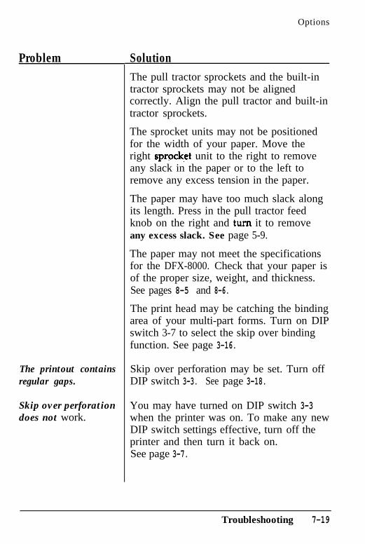
Options
Problem
The printout containsregular gaps.
Skip over perforationdoes not work.
SolutionThe pull tractor sprockets and the built-intractor sprockets may not be alignedcorrectly. Align the pull tractor and built-intractor sprockets.
The sprocket units may not be positionedfor the width of your paper. Move theright sprwket unit to the right to removeany slack in the paper or to the left toremove any excess tension in the paper.
The paper may have too much slack alongits length. Press in the pull tractor feedknob on the right and turn it to removeany excess slack. See page 5-9.
The paper may not meet the specificationsfor the DFX-8000. Check that your paper isof the proper size, weight, and thickness.See pages 8-5 and 8-6.
The print head may be catching the bindingarea of your multi-part forms. Turn on DIPswitch 3-7 to select the skip over bindingfunction. See page 3-16.
Skip over perforation may be set. Turn offDIP switch 3-3. See page 3-18.
You may have turned on DIP switch 3-3when the printer was on. To make any newDIP switch settings effective, turn off theprinter and then turn it back on.See page 3-7.
Troubleshooting 7-19
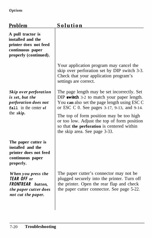
Options
Problem SolutionA pull tractor isinstalled and theprinter does not feedcontinuous paperproperly (continued).
Skip over perforationis set, but theperforation does notfall in the center ofthe skip.
The paper cutter isinstalled and theprinter does not feedcontinuous paperproperly.
When you press theTEAR OFF orFRONTREAR button,the paper cutter doesnot cut the paper.
Your application program may cancel theskip over perforation set by DIP switch 3-3.Check that your application program’ssettings are correct.
The page length may be set incorrectly. SetDIP swi&ch 3-2 to match your paper length.You can also set the page length using ESC Cor ESC C 0. See pages 3-17, 9-13, and 9-14.
The top of form position may be too highor too low. Adjust the top of form positionso that the perforation is centered withinthe skip area. See page 3-33.
The paper cutter’s connector may not beplugged securely into the printer. Turn offthe printer. Open the rear flap and checkthe paper cutter connector. See page 5-22.
7-20 Troubleshooting
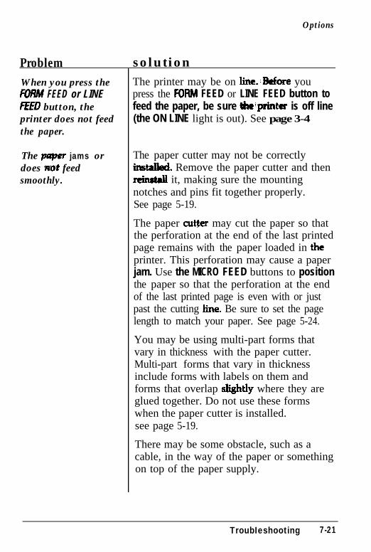
Options
Problem solution When you press the FEED or LINEITED button, theprinter does not feedthe paper.
The puper jams ordoes tiot feedsmoothly.
The printer may be on line..Before youpress the FDRM FEED or LINE FEED button tofeed the paper, be sure Wprinter is off line(the ON LINE light is out). See page 3-4
The paper cutter may not be correctlyins-. Remove the paper cutter and thenrein&l it, making sure the mountingnotches and pins fit together properly.See page 5-19.
The paper cut&r may cut the paper so thatthe perforation at the end of the last printedpage remains with the paper loaded in theprinter. This perforation may cause a paperjam. Use the MICRO FEED buttons to positionthe paper so that the perforation at the endof the last printed page is even with or justpast the cutting he. Be sure to set the pagelength to match your paper. See page 5-24.
You may be using multi-part forms thatvary in thickness with the paper cutter.Multi-part forms that vary in thicknessinclude forms with labels on them andforms that overlap sbghtly where they areglued together. Do not use these formswhen the paper cutter is installed.see page 5-19.
There may be some obstacle, such as acable, in the way of the paper or somethingon top of the paper supply.
TroubIeshooting 7-21
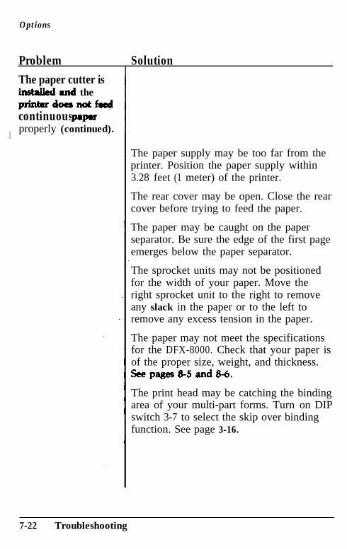
Options
Problem SolutionThe paper cutter isin&a&&and theprinttwdoe6notfwtjcontinuous p8paproperly (continued).
I
The paper supply may be too far from theprinter. Position the paper supply within3.28 feet (1 meter) of the printer.
The rear cover may be open. Close the rearcover before trying to feed the paper.
The paper may be caught on the paperseparator. Be sure the edge of the first pageemerges below the paper separator.
The sprocket units may not be positionedfor the width of your paper. Move theright sprocket unit to the right to removeany slack in the paper or to the left toremove any excess tension in the paper.
The paper may not meet the specificationsfor the DFX-8000. Check that your paper isof the proper size, weight, and thickness.Seepages&5and&6.
The print head may be catching the bindingarea of your multi-part forms. Turn on DIPswitch 3-7 to select the skip over bindingfunction. See page 3-16.
7-22 Troubleshooting
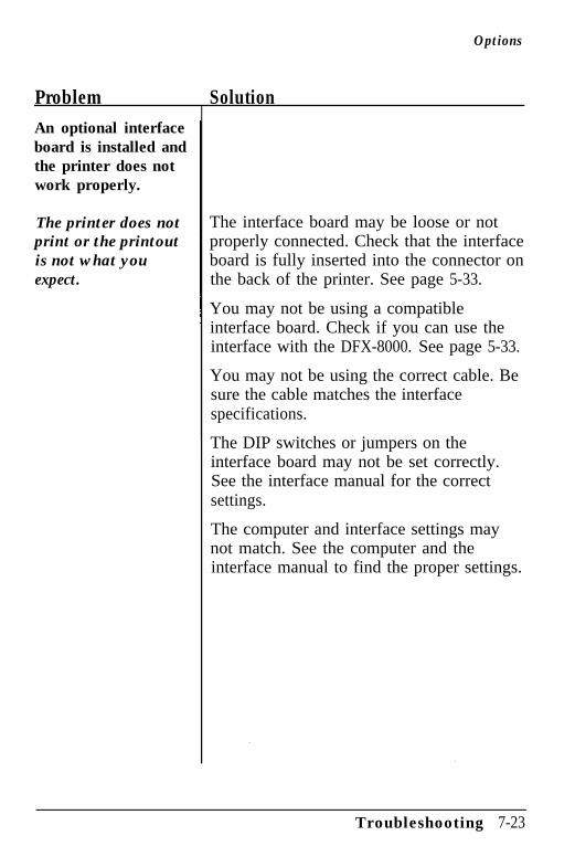
Options
Problem SolutionAn optional interfaceboard is installed andthe printer does notwork properly.
The printer does notprint or the printoutis not what youexpect.
The interface board may be loose or notproperly connected. Check that the interfaceboard is fully inserted into the connector onthe back of the printer. See page 5-33.
You may not be using a compatibleinterface board. Check if you can use theinterface with the DFX-8000. See page 5-33.
You may not be using the correct cable. Besure the cable matches the interfacespecifications.
The DIP switches or jumpers on theinterface board may not be set correctly.See the interface manual for the correctsettings.
The computer and interface settings maynot match. See the computer and theinterface manual to find the proper settings.
Troubleshooting 7-23
Chapter 8Technical Specifications
Printer Specifications ................................................. 8-2Printing................................................................ 8-2Paper................................................................... 8-3Mechanical ........................................................... 8-9Electrical .............................................................. 8-10Environment ......................................................... 8-10
Interface Specifications ............................................... 8-11Parallel interface .................................................... 8-11Serial interface ...................................................... 8-15
Initialization ............................................................. 8-17Default settings ...................................................... 8-17
Technical Specifications 8-1
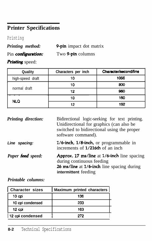
Printer Specifications
Printing
Printing method:
Pin coll&uration:
PAI* speed:
9-pin impact dot matrix
Two 9-pin columns
Quality Characters per inch
high-speed draft 10
CharacterbccndAine
1066I
normal draft10 600
12 960- - -
NLQ10 160
12 192
Printing direction: Bidirectional logic-seeking for text printing.Unidirectional for graphics (can also beswitched to bidirectional using the propersoftware command).
Line spacing: l/binch, l/8-inch, or programmable inincrements of 1/216th of an inch
Paper fked speed:
Printable columns:
Approx. 17 ms/line at l/6-inch line spacingduring continuous feeding26 ms/line at llbinch line spacing duringintermittent feeding
1 Character sizes 1 Maximum printed characters 1
1Ocpi 136
10 cpi condensed 233
12cpi 163
1 12 cpi condensed I 272 I
8-2 Technical Specifications
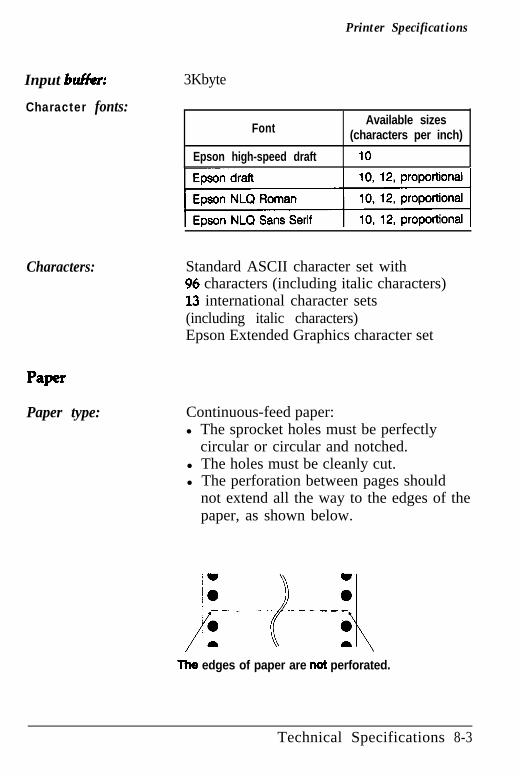
Printer Specifications
Input bufkr: 3Kbyte
Character fonts:Font
Epson high-speed draft
Available sizes(characters per inch)
10
Characters: Standard ASCII character set with96 characters (including italic characters)13 international character sets(including italic characters)Epson Extended Graphics character set
Paper
Paper type: Continuous-feed paper:l The sprocket holes must be perfectly
circular or circular and notched.l The holes must be cleanly cut.l The perforation between pages should
not extend all the way to the edges of thepaper, as shown below.
~~-+~
Ths edges of paper are not perforated.
Technical Specifications 8-3
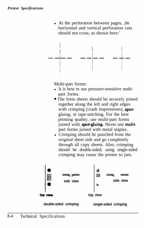
Printer Specifications
l At the perforation between pages, ,thehorizontal and vertical perforation cutsshould not cross, as shown here:’
II I II I Is-w- -e-m -seI I II I I
Multi-part forms:l It is best to use pressure-sensitive multi-
part forms.. The form sheets should be securely joined
together along the left and right edgeswith crimping (crash impressions), spot-gluing, or tape-stitching. For the bestprinting quality, use multi-part formsjoined with .spot-gluing. Never use multi-part forms joined with metal staples.
l Crimping should be punched from theoriginal sheet side and go completelythrough all copy sheets. Also, crimpingshould be double-sided; using single-sidedcrimping may cause the printer to jam.
a auuu -v uuu w =nnn side view side view
.a a
topvhw top view
double-sided crimping single-sided crimping
8-4 Technical Specifications
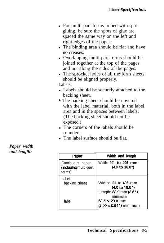
Printer Specifications
Paper widthand length:
l For multi-part forms joined with spot-gluing, be sure the spots of glue arespaced the same way on the left andright edges of the paper.
l The binding area should be flat and haveno creases.
l Overlapping multi-part forms should bejoined together at the top of the pagesand not along the sides of the pages.
l The sprocket holes of all the form sheetsshould be aligned properly.
Labels:l Labels should be securely attached to the
backing sheet.* The backing sheet should be covered
with the label material, both in the labelarea and in the spaces between labels.(The backing sheet should not beexposed.)
l The corners of the labels should berounded.
l The label surface should be flat.
PeperContinuous paper(in&ding multi-partforms)
Labelsbacking sheet
label
Width and length
Width: 101 to 406 mm(4.0 to 16.0”)
Width: 101 to 406 mm(4.0 to lS.Ol)
Length: 88.9 mm (3.5”)minimum
63.5 x 23.8 mm(2.50 x 0.94”) minimum
Technical Specifications 8-5
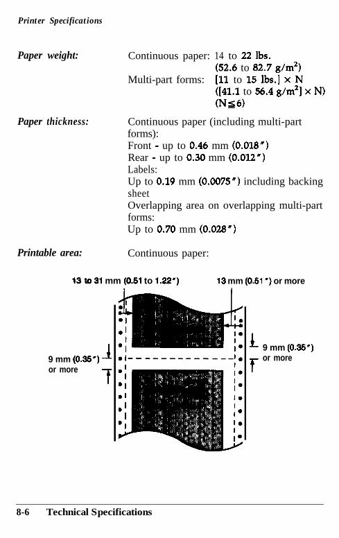
Printer Specifications
Paper weight: Continuous paper: 14 to 22 lbs.(52.6 to 82.7 g/m2)
Multi-part forms: [ll to 15 lbs.] x N([41.1 to 56.4 g/m21 x N)oJs6)
Paper thickness: Continuous paper (including multi-partforms):Front - up to 0.46 mm (0.018")Rear - up to 0.30 mm (0.012")Labels:Up to 0.19 mm (0.0075") including backingsheetOverlapping area on overlapping multi-partforms:Up to 0.70 mm (0.028")
Printable area: Continuous paper:
13 tc 31 mm (0.51 to 1.22”) 13 mm (0.51”) or more
9 mm (0.35”) 1
or moref
L 9 mm (0.35”)
for more
8-6 Technical Specifications
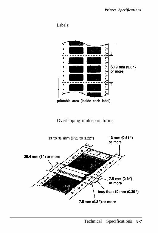
Printer Specifications
Labels:
printable area (inside each label)
Overlapping multi-part forms:
13 to 31 mm (0.51 to 1.22”),I
13 mm (0.51”)or more
25.4 mm (1”) or more
than 10 mm (0.39”)
7.5 mm (0.3”) or more
Technical Specifications 8-7
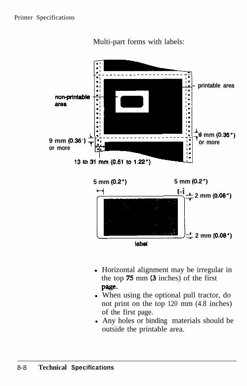
Printer Specifications
Multi-part forms with labels:
- printable area
9 mm (OS*) T ;Ior more ,3 to;,;
+9 mm (0.35”)or more
5 mm (0.2”) 5 mm (0.2”)
H t-i* 2 mm (0.05”)
2 2 mm (0.05”)
l Horizontal alignment may be irregular inthe top 75 mm (3 inches) of the firstPage.
l When using the optional pull tractor, donot print on the top 120 mm (4.8 inches)of the first page.
l Any holes or binding materials should beoutside the printable area.
8-8 Technical Specifications
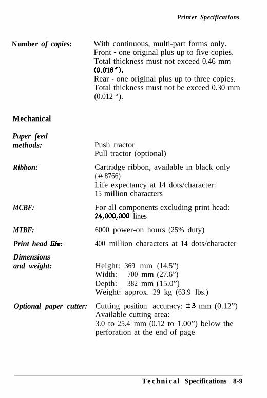
Printer Specifications
Number of copies:
Mechanical
Paper feedmethods:
Ribbon:
MCBF:
MTBF:
Print head lik
Dimensionsand weight:
Optional paper cutter:
With continuous, multi-part forms only.Front - one original plus up to five copies.Total thickness must not exceed 0.46 mm(O.ol&? “).Rear - one original plus up to three copies.Total thickness must not be exceed 0.30 mm(0.012 “).
Push tractorPull tractor (optional)
Cartridge ribbon, available in black only( # 8766)Life expectancy at 14 dots/character:15 million characters
For all components excluding print head:24,ooo,ooo lines
6000 power-on hours (25% duty)
400 million characters at 14 dots/character
Height: 369 mm (14.5”)Width: 700 mm (27.6”)Depth: 382 mm (15.0”)Weight: approx. 29 kg (63.9 lbs.)
Cutting position accuracy: f3 mm (0.12”)Available cutting area:3.0 to 25.4 mm (0.12 to 1.00”) below theperforation at the end of page
Technical Specifications 8-9
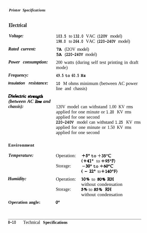
Printer Specifications
Electrical
Voltage:
Rated current:
Power consumption:
Frequency:
Insulation resistance:
LHeIectn’c stmgth(between AC he andchassis):
Environment
Temperature:
Humidity:
Operation angle:
103.5 to 132.0 VAC (120V model)198.0 to 264.0 VAC (220-240V model)
7A (l2OV model)5A (220-240V model)
200 watts (during self test printing in draftmode)
49.5 to 60.5 Hz
10 M ohms minimum (between AC powerline and chassis)
120V model can withstand 1.00 KV rmsapplied for one minute or 1.20 KV rmsapplied for one second220-240V model can withstand 1.25 KV rmsapplied for one minute or 1.50 KV rmsapplied for one second
Operation: +5O to +35"c(+41° to +95”F)
Storage: -30" to +60°c( - 22O to +140”F)
Operation: 10% to 80% FWwithout condensation
Storage: 5% to 85% RI4without condensation
0”
8-10 Technical Specifications
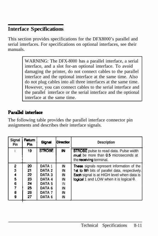
Interface Specifications
This section provides specifications for the DFX8000’s parallel andserial interfaces. For specifications on optional interfaces, see theirmanuals.
WARNING: The DFX-8000 has a parallel interface, a serialinterface, and a slot for-an optional interface. To avoiddamaging the printer, do not connect cables to the parallelinterface and the optional interface at the same time. Alsodo not plug cables into all three interfaces at the same time.However, you can connect cables to the serial interface andthe parallel interface or the serial interface and the optionalinterface at the same time.
The following table provides the parallel interface connector pinassignments and describes their interface signals.
SignalPin
1
WurnPin Signal Dkectk~
i-t
19 m IN
I
I 20 DATA 1 IN21 DATA 2 IN22 DATA 3 IN23 DATA 4 IN24 DATA 5 IN25 DATA 6 IN26 DATA 7 IN27 DATA 6 IN
Description
STRQBE pulse to read data. Pulse widthrnd be more than 0.5 microseconds atthe fieceiving terminal.
Theqe signals represent information of the1st tD 9th bits of parallel data, respectively.Each signal is at HIGH level when data islogidal 1 and LOW when it is logical 0.
Technical Specifications 8-11
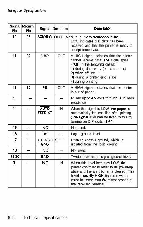
Interface Specifications
Signal ReturnPin Pin Signal Direction -lptiofl
10 28 m OUT About a 1Pmicrosecond pulse.LOW indicates that data has beenreceived and that the printer is ready toaccept more data.
11 29 BUSY OUT A HIGH signal indicates that the printercannot receive data. The signal goesHtGH in the following cases:1) during data entry (ea. char. time)2) when off line
12 30 PE
3) during a printer error state4) during printing
OUT A HIGH signal indicates that the printeris out of paper.
13 - - - Pulled up to +5 volts through 3.3K ohmresistance.
14 - m IN When this signal is LOW, the paper isFEED automatically fed one line after printing.
(The signal level can be fixed to this byturning on DIP switch 2-4.)
15 - NC - Not used.
16 - ov - Logic ground level.
17 - C H A S S I S - Printer’s chassis ground, which isGND isolated from the logic ground.
18 - NC - Not used.
19-30 - GND - Twisted-pair return signal ground level.
31 - lNlf IN When this level becomes LOW, theprinter controller is reset to its power-upstate and the print buffer is cleared. Thislevel is usually~H/GH; its pulse widthmust be more man 56 microseconds atthe receiving terminal.
8-12 Technical Specifications
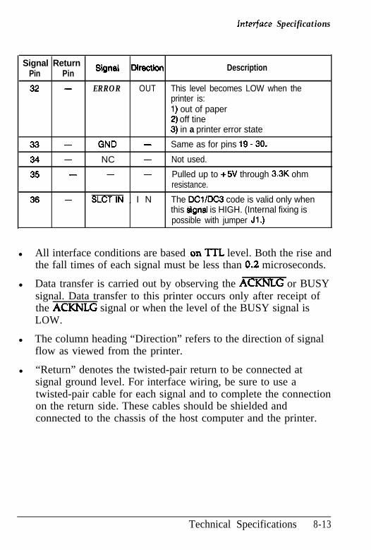
Interface Specifications
Signal ReturnPin Pin Signal Oirection Description
32 - ERROR OUT This level becomes LOW when theprinter is:1) out of paper2) off tine3) in a printer error state
33 - GND - Same as for pins 19 - 30.
34 - NC - Not used.
35 - - - Pulled up to +5V through 3.3K ohmresistance.
36 - SLCTIN I N The DClIDC3 code is valid only whenthis hignal is HIGH. (Internal fixing ispossible with jumper Jl.)
l All interface conditions are based .on TTL level. Both the rise andthe fall times of each signal must be less than 0.2 microseconds.
l Data transfer is carried out by observing the ACKNLG or BUSYsignal. Data transfer to this printer occurs only after receipt ofthe ACKNLG signal or when the level of the BUSY signal isLOW.
l The column heading “Direction” refers to the direction of signalflow as viewed from the printer.
l “Return” denotes the twisted-pair return to be connected atsignal ground level. For interface wiring, be sure to use atwisted-pair cable for each signal and to complete the connectionon the return side. These cables should be shielded andconnected to the chassis of the host computer and the printer.
Technical Specifications 8-13
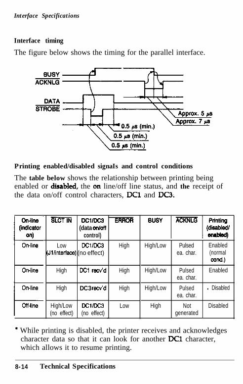
Interface Specifications
Interface timing
The figure below shows the timing for the parallel interface.
Printing enabled/disabled signaIs and control conditions
The table below shows the relationship between printing beingenabled or diiiabled, the 6n line/off line status, and the receipt ofthe data on/off control characters, DC1 and DC3.
SLCT DC1mC3(data on/off
control)
HighLow DC1 /DC3 High/Low Pulsed Enabled(Jlanterface) (no effect) ea. char. (normal
cond.)
High DC1 recv’d High High/Low Pulsed Enabledea. char.
High DC3 recv’d High High/Low Pulsed l Disabledea. char.
High/Low DClIDC3 Low High Not Disabled(no effect) (no effect) generated
* While printing is disabled, the printer receives and acknowledgescharacter data so that it can look for another DC1 character,which allows it to resume printing.
8-14 Technical Specifications
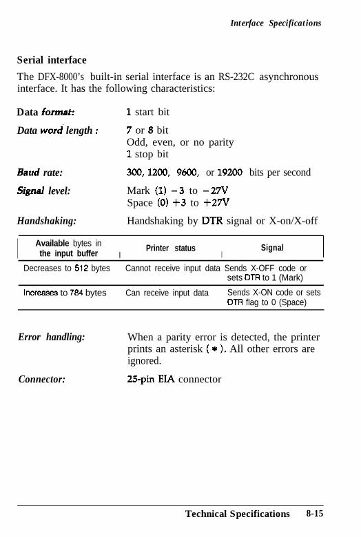
Interface Specifications
Serial interface
The DFX-8000’s built-in serial interface is an RS-232C asynchronousinterface. It has the following characteristics:
Data Jomat:
Data word length :
Baud rate:
Signal level:
Handshaking:
1 start bit
7 or 8 bitOdd, even, or no parity1 stop bit
300, 1200, 9600, or 19200 bits per second
Mark (1) -3 to -27VSpace (0) +3 to +27V
Handshaking by DTR signal or X-on/X-off
I Available bytes inthe input buffer I
Printer statusI
Signal
Decreases to 512 bytes Cannot receive input data Sends X-OFF code orsets DTR to 1 (Mark)
Increases to 784 bytes Can receive input data Sends X-ON code or setsDTR flag to 0 (Space)
Error handling: When a parity error is detected, the printerprints an asterisk ( * ). All other errors areignored.
Connector: 25pin EIA connector
Technical Specifications 8-15
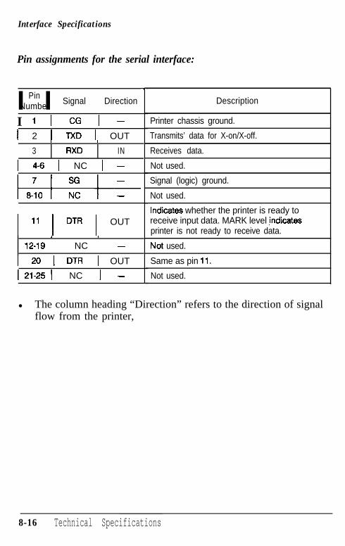
Interface Specifications
Pin assignments for the serial interface:
PinI INumber Signal Direction
I 1 1 CG 1 -1 2 1 TXD 1 OUT
I I
3 RXD IN
1 4-6 1 NC 1 -
1 11 ( DTR 1 OUTI I
12-19 NC -
1 20 1 DTR 1 OUT
121-251 NC 1 -
T-
Description
Printer chassis ground.
Transmits’ data for X-on/X-off.
Receives data.
Not used.
Signal (logic) ground.
Not used.
Indicates whether the printer is ready toreceive input data. MARK level ,indicatesprinter is not ready to receive data.
Not used.
Same as pin 11.
Not used.
l The column heading “Direction” refers to the direction of signalflow from the printer,
8-16 Technical Specifications
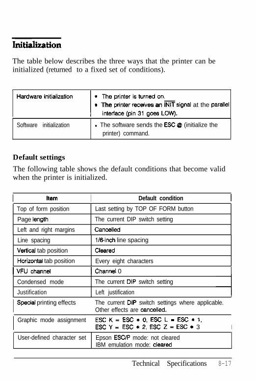
Initition
The table below describes the three ways that the printer can beinitialized (returned to a fixed set of conditions).
yiizzGr~~;;“~l~~~~~,l The pnnter recerves an lNiT srgnai at the parallel
Software initialization l The software sends the ESC @ (initialize theprinter) command.
Default settings
The following table shows the default conditions that become validwhen the printer is initialized.
Item I Default condition
Top of form position
Page length
Left and right margins
Last setting by TOP OF FORM button
The current DIP switch setting
Canceiled
Line spacing
Vertical tab position
Horizontal tab position
I VFU channel
Condensed mode
Justification
l/Sinch line spacing
Cleared
Every eight characters
1 Channel 0
The current DIP switch setting
Left justification
I Special printing effects The current DIP switch settings where applicable.Other effects are cancelled.
I Graphic mode assignment ESC K = ESC * 0, ESC L = ESC * 1,ESC Y = ESC * 2. ESC Z = ESC * 3 I
User-defined character set Epson ESClP mode: not clearedIBM emulation mode: cleared
Technical Specifications 8-17
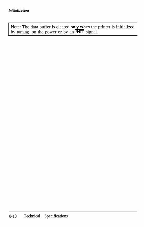
Initialization
Note: The data buffer is cleared onkhen the printer is initializedby turning on the power or by an INIT signal.
8-18 Technical Specifications
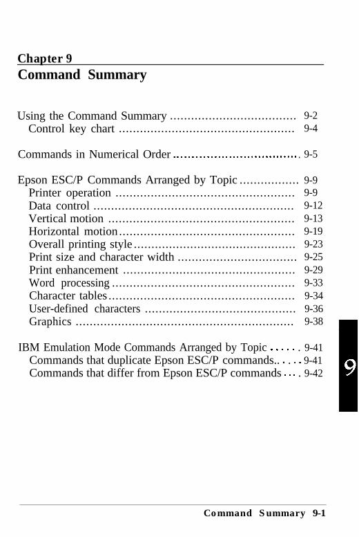
Chapter 9Command Summary
Using the Command Summary .................................... 9-2Control key chart .................................................. 9-4
Commands in Numerical Order . . . . . . . . . . . . . . . . . . . . . . . . . . . . . . . . . . . 9-5
Epson ESC/P Commands Arranged by Topic ................. 9-9Printer operation ................................................... 9-9Data control ......................................................... 9-12Vertical motion ..................................................... 9-13Horizontal motion .................................................. 9-19Overall printing style .............................................. 9-23Print size and character width .................................. 9-25Print enhancement ................................................. 9-29Word processing .................................................... 9-33Character tables ..................................................... 9-34User-defined characters ........................................... 9-36Graphics .............................................................. 9-38
IBM Emulation Mode Commands Arranged by Topic . . . . . . 9-41Commands that duplicate Epson ESC/P commands.. . . . . 9-41Commands that differ from Epson ESC/P commands . . . . 9-42
Command Summary 9-1
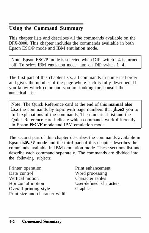
Using the Command Summary
This chapter lists and describes all the commands available on theDFX-8000. This chapter includes the commands available in bothEpson ESC/P mode and IBM emulation mode.
Note: Epson ESC/P mode is selected when DIP switch l-4 is turnedoff. To select IBM emulation mode, turn on DIP switch l-4.
The first part of this chapter lists, all commands in numerical orderand gives the number of the page where each is fully described. Ifyou know which command you are looking for, consult thenumerical list.
Note: The Quick Reference card at the end of this manual alsoIists the commands by topic with page numbers that ,direct you tofull explanations of the commands, The numerical list and theQuick Reference card indicate which commands work differentlyin Epson ESC/P mode and IBM emulation mode.
The second part of this chapter describes the commands available inEpson ESC/P mode and the third part of this chapter describes thecommands available in IBM emulation mode. These sections list anddescribe each command separately. The commands are divided intothe following subjects:
Printer operationData controlVertical motionHorizontal motionOverall printing stylePrint size and character width
Print enhancementWord processingCharacter tablesUser-defined charactersGraphics
9-2 codsulmnaIy
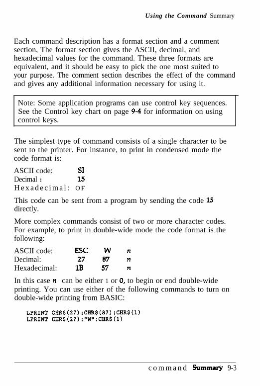
Using the Command Summary
Each command description has a format section and a commentsection, The format section gives the ASCII, decimal, andhexadecimal values for the command. These three formats areequivalent, and it should be easy to pick the one most suited toyour purpose. The comment section describes the effect of the commandand gives any additional information necessary for using it.
Note: Some application programs can use control key sequences.See the Control key chart on page 9-4 for information on usingcontrol keys.
The simplest type of command consists of a single character to besent to the printer. For instance, to print in condensed mode thecode format is:
ASCII code: SIDecimal : 15H e x a d e c i m a l : O F
This code can be sent from a program by sending the code 15directly.
More complex commands consist of two or more character codes.For example, to print in double-wide mode the code format is thefollowing:
ASCII code: ESC W nDecimal: 27 87 nHexadecimal: 1B 57 n
In this case n can be either 1 or 0, to begin or end double-wideprinting. You can use either of the following commands to turn ondouble-wide printing from BASIC:
LPRINT CHR$(27):CIiR$(87):CHR$tl)LPRINT CHR$(27):"W":CHR$(l)
c o m m a n d sumy 9-3
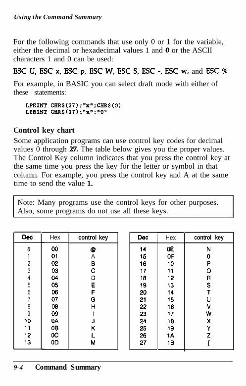
Using the Command Summary
For the following commands that use only 0 or 1 for the variable,either the decimal or hexadecimal values 1 and 0 or the ASCIIcharacters 1 and 0 can be used:
ESC U, ESC x, ESC p, ESC W, ESC S, ESC -, ESC w, and ESC %
For example, in BASIC you can select draft mode with either ofthese statements:
LPRINT CHR$(27);'x":'CHR$(O)LPRINT CHR$(27):"x":"O"
Control key chartSome application programs can use control key codes for decimalvalues 0 through 27. The table below gives you the proper values.The Control Key column indicates that you press the control key atthe same time you press the key for the letter or symbol in thatcolumn. For example, you press the control key and A at the sametime to send the value 1.
Note: Many programs use the control keys for other purposes.Also, some programs do not use all these keys.
DeC
0 00 @ 14 OE1 01 A 15 OF2 02 B 16 103 03 C 17 114 04 D 18 125 05 E 19 136 06 F 20 147 07 G 21 158 08 H 22 169 09 I 23 17
10 OA J 24 1811 OB K 25 1912 oc L 26 1A13 OD M 27 18
Hex control key DeC Hex control key
N0P0RSTUvWXYZ
1
9-4 Command Summary
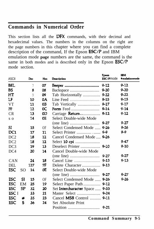
Commands in Numerical Order
This section lists all the DFX commands, with their decimal andhexadecimal values. The numbers in the columns on the right arethe page numbers in this chapter where you can find a completedescription of the command, If the Epson ESC/P and IBMemulation mode page numbers are the same, the command is thesame in both modes and is described only in the Epson ESUPmode section.
ASCIIEP- lBM
Dee Hex Delcrbtion FSC/P mode l muletion mode
BEL 7 07BS 8 08HT 9 09LF 10 OAVT 11 OBFF 12 ocCR 13 ODs o 14 OE
SI 15 OFDC1 17 11DC2 18 12DC2 18 12DC3 19 13DC4 20 14
CAN 24 18DEL 127 7FESC SO 14 OE
ESC SI 15 OFESC EM 25 19ESC SP 32 20ESC I 33 21ESC # 35 23ESC $ 36 24
Beeper ............................ 9-12Backspace ........................ 9-20Tab Horizontally .............. 9-22Line Feed ........................ 9-15Tab Vertically .................. 9-17Form Feed ....................... 9-14Carriage Return.. .............. 9-12Select Double-wide Mode(one line) ........................ 9-27Select Condensed Mode ..... 9-26Select Printer ............ . ...... 9-9Cancel Condensed Mode .... 9-26Select 10 cpi ....................Deselect Printer ................ 9-10Cancel Double-wide Mode(one line) ........................ 9-27Cancel Line ..................... 9-13Delete Character ............... 9-13Select Double-wide Mode(one line) ........................ 9-27Select Condensed Mode ..... 9-26Select Paper Path .............. 9-12Set Intercharacter Space ..... 9-33Master Select ................... 9-24Cancel MSB Control ......... 9-11Set Absolute PrintPosition .......................... 9-21
9-129-209-229-159-179-149-12
9-279-269-9
9-479-10
9-279-13
9-279-26
Command Summary 9-5
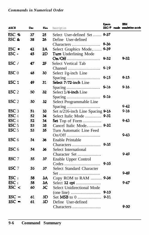
Commands in Numerical Order
ASCIIElnon mbl
oec HCX Description EsC/P nnlde ean&tkmlnode
ESC % 37 25ESC & 38 26
ESC * 42 2AESC - 45 2D
ESC / 47 2F
ESC 0 48 30
ESC 1 49 31
ESC 2 50 32
ESC 2 50 32
ESC 3 51 33ESC 4 52 34ESC 4 52 34ESC 5 53 3sESC 5 53 35
ESC 6 54 36
ESC 6 54 36
ESC 7 55 37
ESC 7 55 37
ESC : 58 3AESC : 58 3AESC < 60 3c
ESC - 61 3DESC = 61 3D
Select User-defined Set ....... 9-37Define User-definedCharacters ....................... 9-36Select Graphics Mode.. ...... 9-39Turn Underlining Modeon/off ........................... 9-32Select Vertical TabChannel .......................... 9-19Select l/g-inch LineSpacing ........................... 9-15Select 7/72-inch LineSpacing ........................... 9-16Select 1/64nch LineSpacing ........................... 9-16Select Programmable LineSpacing ...........................Set n/216-inch Line Spacing 9-16Select Italic Mode ............. 9-31set Top of Form ...............Cancel Italic Mode.. .......... 9-32Turn Automatic Line FeedOn/Off ...........................Enable PrintableCharacters ....................... 9-35Select InternationalCharacter Set ...................Enable Upper ControlCodes ............................. 9-35Select Standard CharacterSet .................................Copy ROM to RAM ......... 9-36Select 12 cpi ....................Select Unidirectional Mode(one line) ........................ 9-10Set MSB to 0 ................... 9-11Define User-definedCharacters .......................
9-32
9-15
9-16
9-429-16
9-43
9-43
9-49
9-49
9-47
9-50
9-6 Command Summary
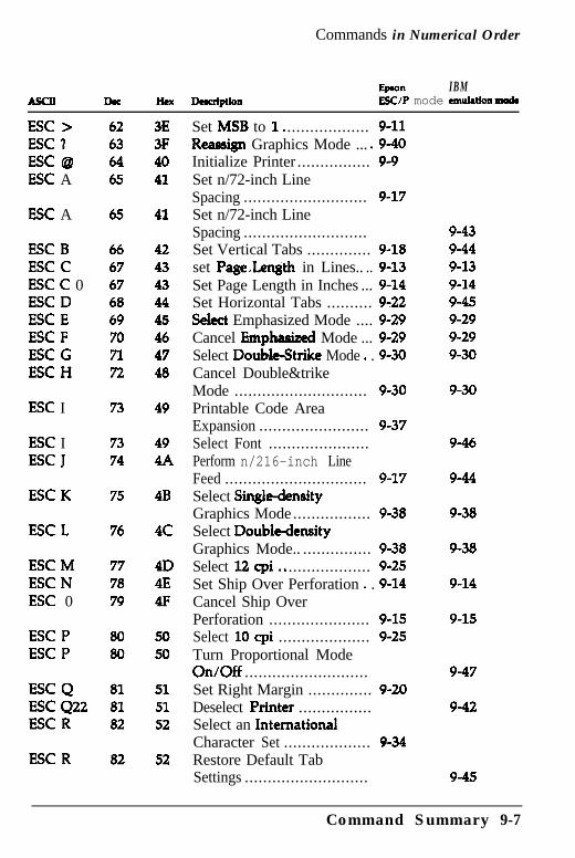
Commands in Numerical Order
bon IBMAscn Dac Hex Duaiption ESUP mode atwhtkmd
ESC > 62 3EESC 1 63 3FESC @ 64 40ESC A 65 41
ESC A 65 41
ESC B 66 42ESC C 67 43ESC C 0 67 43ESC D 68 44ESC E 69 45ESC F 70 46ESC G 71 47ESC H 72 48
ESC I 73 49
ESC IESC J
7374
494A
ESC K 75 4B
ESC L 76 4c
ESC M 77 4DESC N 78 4EESC 0 79 4F
ESC P 80 50ESC P 80 50
ESC Q 81 51ESC 422 81 51ESC R 82 52
ESC R 82 52
Set MSB to 1. .................. 9-11Reassign Graphics Mode ... .9-40Initialize Printer ................ 9-9Set n/72-inch LineSpacing ........................... 9-17Set n/72-inch LineSpacing ...........................Set Vertical Tabs .............. 9-18set Pa&eLength in Lines.. .. 9-13Set Page Length in Inches ... 9-14Set Horizontal Tabs .......... 9-22!Select Emphasized Mode .... 9-29Cancel Ernphaaized Mode ... 9-29Select Double&trike Mode . . 9-30Cancel Double&trikeMode ............................. 9-30Printable Code AreaExpansion ........................ 9-37Select Font ......................Perform n/216-inch LineFeed ............................... 9-17Select Single-densityGraphics Mode................. 9-38Select Double-densityGraphics Mode.. ............... 9-38Select 12 cpi.. .................. 9-25Set Ship Over Perforation . . 9-14Cancel Ship OverPerforation ...................... 9-15Select 10 cpi .................... 9-25Turn Proportional ModeOn/Off ...........................Set Right Margin .............. 9-20Deselect Printer ................Select an InternationalCharacter Set ................... 9-34Restore Default TabSettings ...........................
9-439-449-139-149-459-299-299-30
9-30
9-46
9-44
9-38
9-38
9-14
9-15
9-47
9-42
9-45
Command Summary 9-7
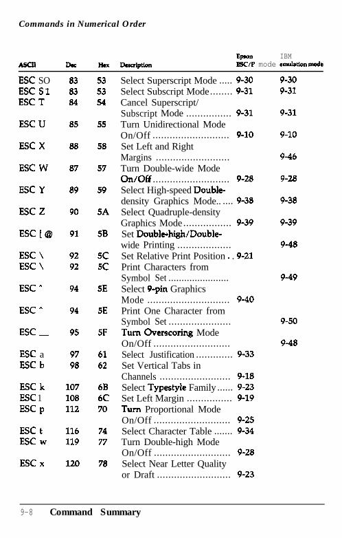
Commands in Numerical Order
Epon IBMASCII Jhc Hex Dcruiption ESC/P mode emulationmode
ESC SO 83 53ESC Sl 83 53ESC T 84 54
ESC U
ESC X
ESC W
ESC Y
ESC Z
ESC [@
ESC \ESC \
ESC a
ESC A
ESC _
ESC aESC b
ESC kESC 1ESC p
ESC tESC w
ESC x
85
88
87
89
90
91
9292
94
94
95
55
58
57
59
5A
5B
SCSC
5E
5E
5F
97 6198 62
107 6B108 6C112 70
116 74119 77
120 78
Select Superscript Mode ..... 9-30Select Subscript Mode........ 9-31Cancel Superscript/Subscript Mode ................ 9-31Turn Unidirectional ModeOn/Off ........................... 9-10Set Left and RightMargins ..........................Turn Double-wide ModeOn/Off ........................... 9-28Select High-speed Double-density Graphics Mode.. .... 9-38Select Quadruple-densityGraphics Mode................. 9-39Set Doublehigh/Double-wide Printing ...................Set Relative Print Position . . 9-21Print Characters fromSymbol Set .......................Select 9-pin GraphicsMode ............................. 9-40Print One Character fromSymbol Set ......................Turn Overscaring ModeOn/Off ...........................Select Justification ............. 9-33Set Vertical Tabs inChannels ......................... 9-18Select Typestyle Family ...... 9-23Set Left Margin ................ 9-19Turn Proportional ModeOn/Off ........................... 9-25Select Character Table ....... 9-34Turn Double-high ModeOn/Off ........................... 9-28Select Near Letter Qualityor Draft .......................... 9-23
9-309-31
9-31
9-10
9-46
9-28
9-38
9-39
9-48
9-49
9-50
9-48
9-8 Command Summary
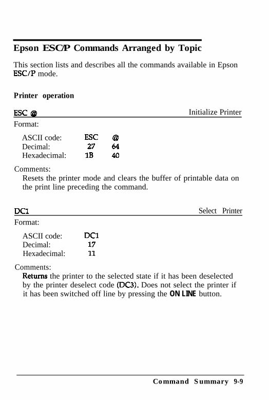
Epson ESC/P Commands Arranged by Topic
This section lists and describes all the commands available in EpsonESUP mode.
Printer operation
ESC @Format:
Initialize Printer
ASCII code: ESC @Decimal: 27 64Hexadecimal: 1B 40
Comments:Resets the printer mode and clears the buffer of printable data onthe print line preceding the command.
DC1Format:
Select Printer
ASCII code:Decimal:Hexadecimal:
Comments:
DC11711
Returns the printer to the selected state if it has been deselectedby the printer deselect code (DC3). Does not select the printer ifit has been switched off line by pressing the ON LINE button.
Command Summary 9-9
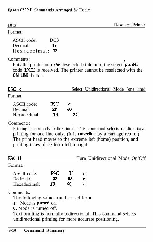
Epson ESUP Commands Arranged by Topic
DC3Format:
Deselect Printer
ASCII code: DC3Decimal: 19H e x a d e c i m a l : 13
Comments:Puts the printer into the deselected state until the select krintercode (ml) is received. The printer cannot be reselected with theON LINE button.
ESC cFormat:
Select Unidirectional Mode (one line)
ASCII code: ESC <Decimal: 27 60Hexadecimal: 1B 3C
Comments:Printing is normally bidirectional. This command selects unidirectionalprinting for one line only. (It is cancelled by a carriage return.)The print head moves to the extreme left (home) position, andprinting takes place from left to right.
ESC UFormat:
Turn Unidirectional Mode On/Off
ASCII code: ESC U nDecimal : 27 85 nHexadecimal: 1B 55 n
Comments:The following values can be used for n:1: Mode is turned on.0: Mode is turned off.Text printing is normally bidirectional. This command selectsunidirectional printing for more accurate positioning.
9-10 Command Summary
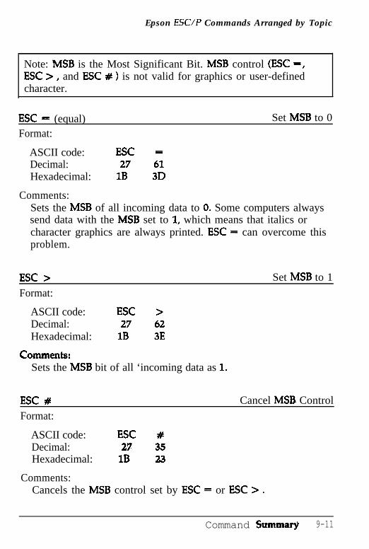
Epson ESUP Commands Arranged by Topic
Note: MSB is the Most Significant Bit. MSB control (ESC =,ESC > , and ESC # ) is not valid for graphics or user-definedcharacter.
ESC = (equal)Format:
Set MSB to 0
ASCII code: ESC =Decimal: 27 61Hexadecimal: 1B 3D
Comments:Sets the MSB of all incoming data to 0. Some computers alwayssend data with the MSB set to 1, which means that italics orcharacter graphics are always printed. ESC = can overcome thisproblem.
ESC >Format:
Set MSB to 1
ASCII code: ESC >Decimal: 27 62Hexadecimal: 1B 3E
CommentS:Sets the MSB bit of all ‘incoming data as 1.
ESC # Cancel MSB Control
Format:
ASCII code: ESC #Decimal: 27 35Hexadecimal: 18 23
Comments:Cancels the MSB control set by ESC = or ESC > .
Command Summa@ 9-11
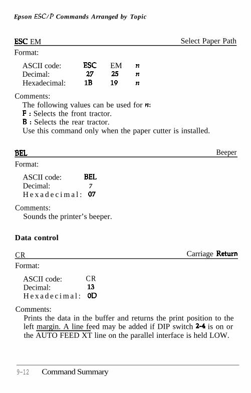
Epson ESUP Commands Arranged by Topic
ESC EMFormat:
Select Paper Path
ASCII code: ESC EM nDecimal: 27 25 nHexadecimal: 1B 19 n
Comments:The following values can be used for n:F : Selects the front tractor.B : Selects the rear tractor.Use this command only when the paper cutter is installed.
BELFormat:
ASCII code: BELDecimal: 7H e x a d e c i m a l : 07
Comments:Sounds the printer’s beeper.
Beeper
Data control
CRFormat:
Carriage Return
ASCII code: CRDecimal: 13H e x a d e c i m a l : OD
Comments:Prints the data in the buffer and returns the print position to theleft margin. A line feed may be added if DIP switch 2-4 is on orthe AUTO FEED XT line on the parallel interface is held LOW.
9-12 Command Summary
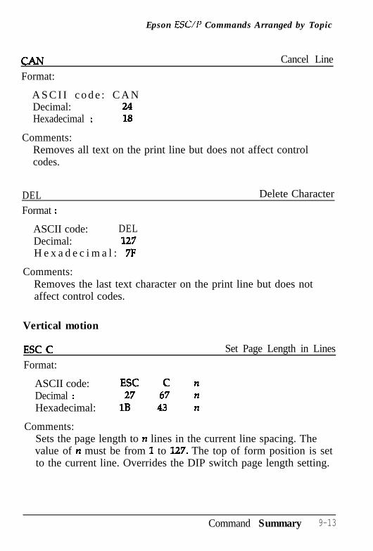
Epson ESC/P Commands Arranged by Topic
Format:
Cancel Line
A S C I I c o d e : C A NDecimal: 24Hexadecimal : 18
Comments:Removes all text on the print line but does not affect controlcodes.
DELFormat :
Delete Character
ASCII code: DELDecimal: 127H e x a d e c i m a l : 7F
Comments:Removes the last text character on the print line but does notaffect control codes.
Vertical motion
ESC CFormat:
Set Page Length in Lines
ASCII code: ESC C nDecimal : 27 67 nHexadecimal: 1B 43 n
Comments:Sets the page length to n lines in the current line spacing. Thevalue of n must be from 1 to 127. The top of form position is setto the current line. Overrides the DIP switch page length setting.
Command Summary 9-13
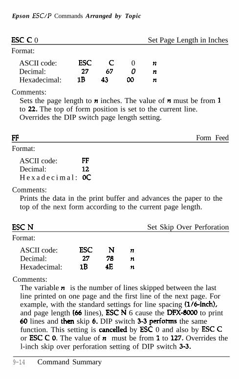
Epson ESC/P Commands Arranged by Topic
ESC C 0Format:
Set Page Length in Inches
ASCII code: ESC C 0 nDecimal: 27 67 0 nHexadecimal: 1B 43 00 n
Comments:Sets the page length to n inches. The value of n must be from 1to 22. The top of form position is set to the current line.Overrides the DIP switch page length setting.
FFFormat:
Form Feed
ASCII code: FFDecimal: 12H e x a d e c i m a l : OC
Comments:Prints the data in the print buffer and advances the paper to thetop of the next form according to the current page length.
ESC NFormat:
Set Skip Over Perforation
ASCII code: ESC N nDecimal: 27 78 nHexadecimal: 1B 4E n
Comments:The variable n is the number of lines skipped between the lastline printed on one page and the first line of the next page. Forexample, with the standard settings for line spacing (l/6-inch),and page length (66 lines), ESC N 6 cause the DFX-so00 to print60 lines and thtn skip 6. DIP switch 3-3 perfofms the samefunction. This setting is cancelled by ESC 0 and also by ESC Cor ESC C 0. The value of n must be from 1 to 127. Overrides thel-inch skip over perforation setting of DIP switch 3-3.
9-14 Command Summary
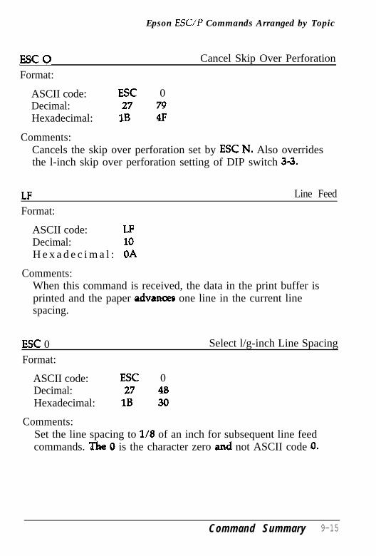
Epson ESUP Commands Arranged by Topic
ESCQFormat:
Cancel Skip Over Perforation
ASCII code: ESC 0Decimal: 27 79Hexadecimal: 1B 4F
Comments:Cancels the skip over perforation set by ESC FJ. Also overridesthe l-inch skip over perforation setting of DIP switch 3-3.
LFFormat:
Line Feed
ASCII code: LFDecimal: 10H e x a d e c i m a l : OA
Comments:When this command is received, the data in the print buffer isprinted and the paper advanoes one line in the current linespacing.
ESC 0Format:
Select l/g-inch Line Spacing
ASCII code: ESC 0Decimal: 27 48Hexadecimal: 1B 30
Comments:Set the line spacing to l/8 of an inch for subsequent line feedcommands. The 0 is the character zero and not ASCII code 0.
Command Summary 9-15
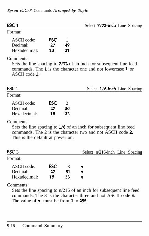
Epson ESC/P Commands Arranged by Topic
ESC 1 Select 7/72-inch Line SpacingFormat:
ASCII code: ESC 1Decimal: 27 49Hexadecimal: 1B 31
Comments:Sets the line spacing to 7/72 of an inch for subsequent line feedcommands. The 1 is the character one and not lowercase L orASCII code 1.
ESC 2Format:
Select l/6-inch Line Spacing
ASCII code: ESC 2Decimal: 27 50Hexadecimal: 1B 32
Comments:Sets the line spacing to l/6 of an inch for subsequent line feedcommands. The 2 is the character two and not ASCII code 2.This is the default at power on.
ESC 3Format:
Select n/216-inch Line Spacing
ASCII code: ESC 3 nDecimal: 27 51 nHexadecimal: 1B 33 n
Comments:Sets the line spacing to n/216 of an inch for subsequent line feedcommands. The 3 is the character three and not ASCII code 3.The value of n must be from 0 to 255.
9-16 Command Summary
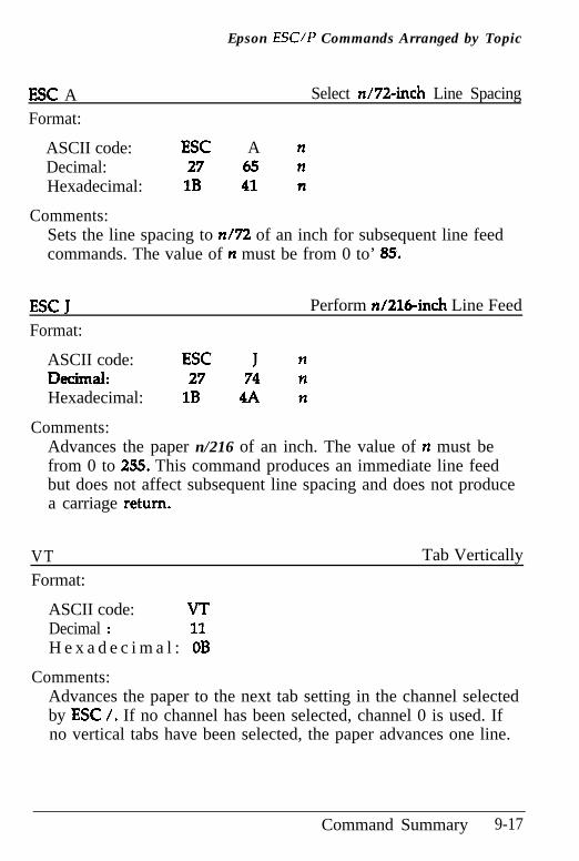
Epson ESUP Commands Arranged by Topic
ESC AFormat:
Select n/72-inch Line Spacing
ASCII code: ESC A nDecimal: 27 65 nHexadecimal: 1B 41 n
Comments:Sets the line spacing to n/72 of an inch for subsequent line feedcommands. The value of n must be from 0 to’ 85.
ESC JFormat:
Perform n/216+& Line Feed
ASCII code: ESC J nDecimal: 27 74 nHexadecimal: 1B 4A n
Comments:Advances the paper n/216 of an inch. The value of n must befrom 0 to 255. This command produces an immediate line feedbut does not affect subsequent line spacing and does not producea carriage return.
VTFormat:
Tab Vertically
ASCII code: VTDecimal : 11H e x a d e c i m a l : OB
Comments:Advances the paper to the next tab setting in the channel selectedby ESC /. If no channel has been selected, channel 0 is used. Ifno vertical tabs have been selected, the paper advances one line.
Command Summary 9-17
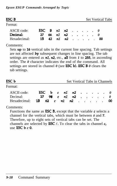
Epson ESUP Commands Arranged by Topic
ESG B Set Vertical TabsFormat:
ASCII code:IkiIIld:Hexadecimal:
Comments:
ESC B nl n2 . . . . . 027 66 nl n2 . . . . . 01B 42 nl n2 . . . . . 00
Sets up to 16 vertical tabs in the current line spacing. Tab settingsare not affected .by subsequent changes in line spacing. The tabsettings are entered as nl, n2, etc., all from 1 to 255, in ascendingorder. The 0 character indicates the end of the command. Allsettings are stored in channel 0 (see ESC b). ESC B 0 clears thetab settings.
ESC b Set Vertical Tabs in ChannelsFormat:
ASCII code: ESC b c nl n2 . . . . . 0Decimal: 27 96 c nl n2 . . . . . 0Hexadecimal: 1B 62 c nl n2 . . . . . 00
Comments:Functions the same as ESC B, except that the variable c selects achannel for the vertical tabs, which must be between 0 and 7.Therefore, up to eight sets of vertical tabs can be set. Thechannels are selected by ESC /. To clear the tabs in channel c,use ESC b c 0.
9-18 Command Summary
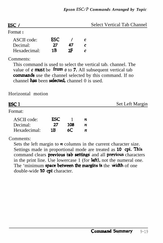
Epson ESC/P Commands Arranged by Topic
ESC / Select Vertical Tab Channel
Format :
ASCII code: ESC / cDecimal: 27 47 cHexadecimal: 1B 2F c
Comments:This command is used to select the vertical tab. channel. Thevalue of c must be fram 0 to 7. All subsequent vertical tabaimnan& use the channel selected by this command. If nochannel hgi been selicted, channel 0 is used.
Horizontal motion
ESCl Set Left Margin
Format:
ASCII code: ESC 1 nDecimal: 27 108 nHexadecimal: 1B 6C n
Comments:Sets the left margin to n columns in the current character size.Settings made in proportional mode are treated as 10 cpi. ,Thiscommand clears @revious ‘tab, set&gs~ and all previous charactersin the print line. Use lowercase 1 (for Ieft), not the numeral one.The ‘minimum space betken the margins is the ‘v&i& of onedouble-wide 10 ‘cpi character.
CommiuulSumluary 9-19
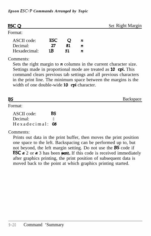
Epson ESUP Commands Arranged by Topic
ESC Q Set Right Margin
Format:
ASCII code: ESC Q nDecimal: 27 81 nHexadecimal: 1B 51 n
Comments:Sets the right margin to n columns in the current character size.Settings made in proportional mode are treated as 10 cpi. Thiscommand clears previous tab settings and all previous charactersin the print line. The minimum space between the margins is thewidth of one double-wide 10 cpi character.
BSFormat:
Backspace
ASCII code: BSDecimal: 8H e x a d e c i m a l : 08
Comments:Prints out data in the print buffer, then moves the print positionone space to the left. Backspacing can be performed up to, butnot beyond, the left margin setting. Do not use the BS code ifESC a 2 or a 3 has been sent, If this code is received immediatelyafter graphics printing, the print position of subsequent data ismoved back to the point at which graphics printing started.
9-20 Command ‘Summary
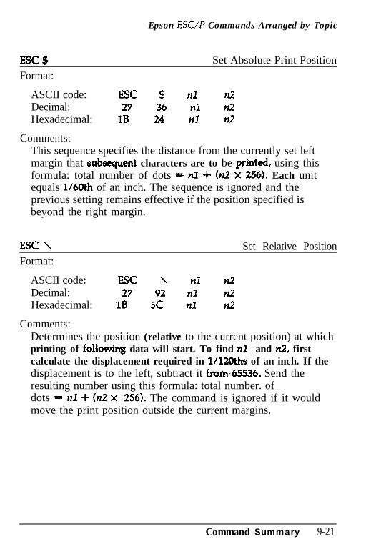
Epson ESUP Commands Arranged by Topic
ESC $Format:
Set Absolute Print Position
ASCII code: ESC $ nl n2Decimal: 27 36 nl n2Hexadecimal: 1B 24 n7 n2
Comments:This sequence specifies the distance from the currently set leftmargin that s&sequent characters are to be printed, using thisformula: total number of dots = nl + (n2 x 256). Each unitequals 1/60th of an inch. The sequence is ignored and theprevious setting remains effective if the position specified isbeyond the right margin.
ESC \ Set Relative PositionFormat:
ASCII code: ESC \ nl n2Decimal: 27 92 nl n2Hexadecimal: 1B 5C nl n2
Comments:Determines the position (relative to the current position) at whichprinting of followiq data will start. To find nl and n2, firstcalculate the displacement required in l/ltoLhs of an inch. If thedisplacement is to the left, subtract it from,65536. Send theresulting number using this formula: total number. ofdots = nl + (n2 x 256). The command is ignored if it wouldmove the print position outside the current margins.
Command Summary 9-21
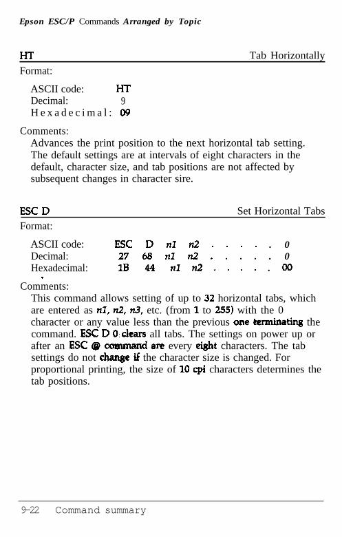
Epson ESC/P Commands Arranged by Topic
HTFormat:
Tab Horizontally
ASCII code: HTDecimal: 9H e x a d e c i m a l : 09
Comments:Advances the print position to the next horizontal tab setting.The default settings are at intervals of eight characters in thedefault, character size, and tab positions are not affected bysubsequent changes in character sire.
ESC D Set Horizontal TabsFormat:
ASCII code:Decimal:Hexadecimal:
.
ESC D nl n2 . . . . . 027 68 nl n2 . . . . . 01B 44 nl n2 . . . . . 00
Comments:This command allows setting of up to 32 horizontal tabs, whichare entered as nl, n2, n3, etc. (from 1 to 255) with the 0character or any value less than the previous one &erminating thecommand. ESC D 0;clears all tabs. The settings on power up orafter an E-SC @ cummand.are every ei&t characters. The tabsettings do not Me .if the character size is changed. Forproportional printing, the size of 10 cpi characters determines thetab positions.
9-22 Command summary
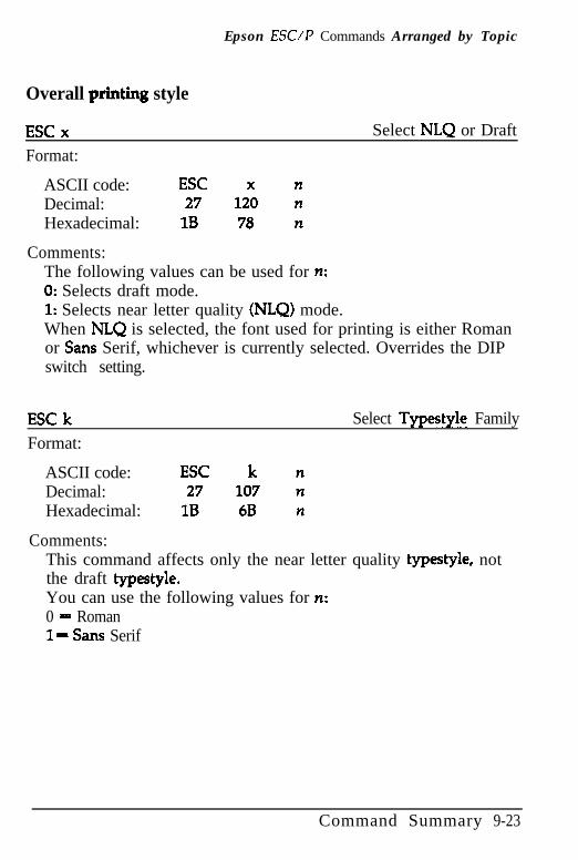
Epson ESUP Commands Arranged by Topic
Overall printing style
ESC xFormat:
Select NLQ or Draft
ASCII code: ESC x nDecimal: 27 120 nHexadecimal: 1B 78 n
Comments:The following values can be used for n:0: Selects draft mode.1: Selects near letter quality (NLQ) mode.When NLQ is selected, the font used for printing is either Romanor Sans Serif, whichever is currently selected. Overrides the DIPswitch setting.
ESC kFormat:
Select Typestyle Family
ASCII code: ESC k nDecimal: 27 107 nHexadecimal: 1B 6B n
Comments:This command affects only the near letter quality typestyle, notthe draft typestyle.You can use the following values for n:0 = Roman1= Sans Serif
Command Summary 9-23
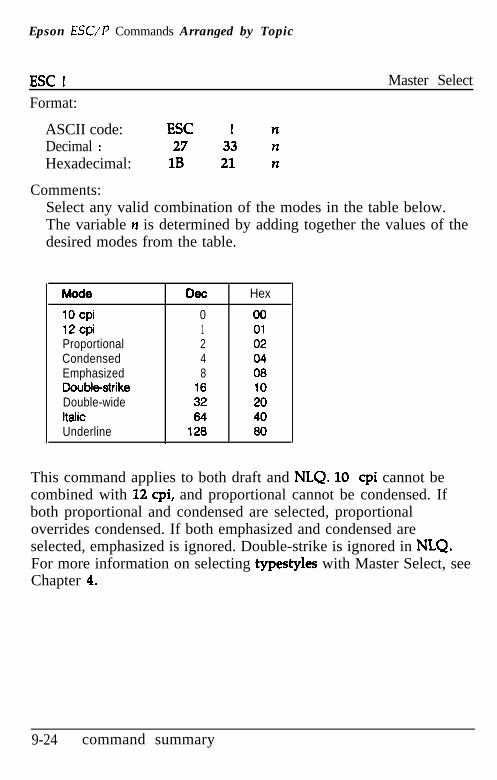
Epson ESUP Commands Arranged by Topic
ESC IFormat:
Master Select
ASCII code: ESC I nDecimal : 27 33 nHexadecimal: 1B 21 n
Comments:Select any valid combination of the modes in the table below.The variable n is determined by adding together the values of thedesired modes from the table.
Mode Dee Hex
10 cpi 0 0012 cpi 1 01Proportional 2 02Condensed 4 04Emphasized 8 08Double-strike 16 10Double-wide 32 20Italic 64 40Underline 126 80
This command applies to both draft and NLQ. 10 cpi cannot becombined with 12 cpi, and proportional cannot be condensed. Ifboth proportional and condensed are selected, proportionaloverrides condensed. If both emphasized and condensed areselected, emphasized is ignored. Double-strike is ignored in NLQ.For more information on selecting typestyles with Master Select, seeChapter 4.
9-24 command summary
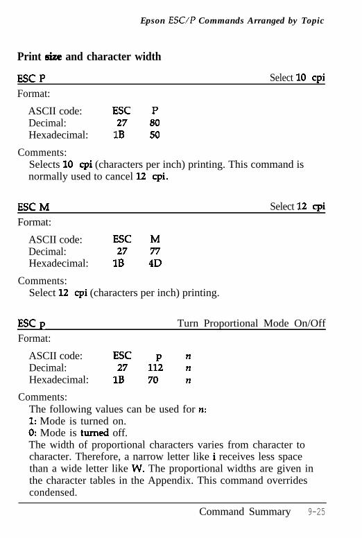
Epson ESUP Commands Arranged by Topic
Print size and character width
ESC PFormat:
Select 10 cpi
ASCII code: ESC PDecimal: 27 80Hexadecimal: 1B 50
Comments:Selects 10 cpi (characters per inch) printing. This command isnormally used to cancel 12 cpi.
ESCMFormat:
ASCII code: ESC MDecimal: 27 77Hexadecimal: 1B 4D
Comments:Select 12 cpi (characters per inch) printing.
Select 12 cpi
ESC p Turn Proportional Mode On/OffFormat:
ASCII code: ESC p nDecimal: 27 112 nHexadecimal: 1B 70 n
Comments:The following values can be used for n:1: Mode is turned on.0: Mode is turned off.The width of proportional characters varies from character tocharacter. Therefore, a narrow letter like i receives less spacethan a wide letter like W. The proportional widths are given inthe character tables in the Appendix. This command overridescondensed.
Command Summary 9-25
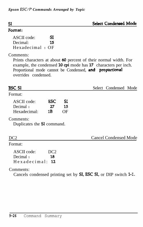
Epson ESUP Commands Arranged by Topic
SI !%hctCon&dMode
ASCII code: ,SIDecimal: 15Hexadecimal : OF
Comments:Prints characters at about 60 percent of their normal width. Forexample, the condensed 10 cpi mode has 17 characters per inch.Proportional mode cannot be Condensed, and propbrtianaloverrides condensed.
Esc SI
Format:
ASCII code: ESC SIDecimal : 27 15Hexadecimal: 1B OF
Comments:Duplicates the SI command.
Select Condensed Mode
DC2Format:
Cancel Condensed Mode
ASCII code: DC2Decimal : 18H e x a d e c i m a l : 12
Comments:Cancels condensed printing set by SI, ESC SI, or DIP switch l-l.
9-26 Command Summary
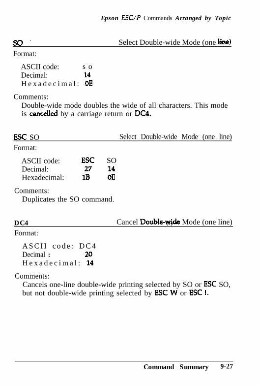
Epson ESUP Commands Arranged by Topic
so.Format:
Select Double-wide Mode (one line)
ASCII code: s oDecimal: 14H e x a d e c i m a l : OE
Comments:Double-wide mode doubles the wide of all characters. This modeis cancelled by a carriage return or DC4.
ESC SO Select Double-wide Mode (one line)
Format:
ASCII code: ESC SODecimal: 27 14Hexadecimal: 1B OE
Comments:Duplicates the SO command.
DC4Format:
Cancel Double-wide Mode (one line)
A S C I I c o d e : D C 4Decimal : 20H e x a d e c i m a l : 14
Comments:Cancels one-line double-wide printing selected by SO or ESC SO,but not double-wide printing selected by ESC W or ESC 1.
Command Summary 9-27
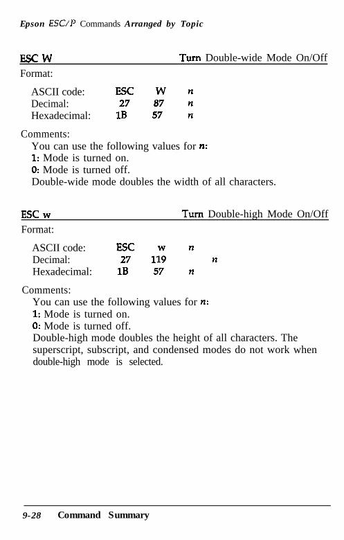
Epson ESC/P Commands Arranged by Topic
ESCW Turn Double-wide Mode On/Off
Format:
ASCII code: ESC W nDecimal: 27 87 nHexadecimal: 1B 57 n
Comments:You can use the following values for n:1: Mode is turned on.0: Mode is turned off.Double-wide mode doubles the width of all characters.
ESC w Turn Double-high Mode On/Off
Format:
ASCII code: ESC w nDecimal: 27 119 nHexadecimal: 1B 57 n
Comments:You can use the following values for n:1: Mode is turned on.0: Mode is turned off.Double-high mode doubles the height of all characters. Thesuperscript, subscript, and condensed modes do not work whendouble-high mode is selected.
9-28 Command Summary
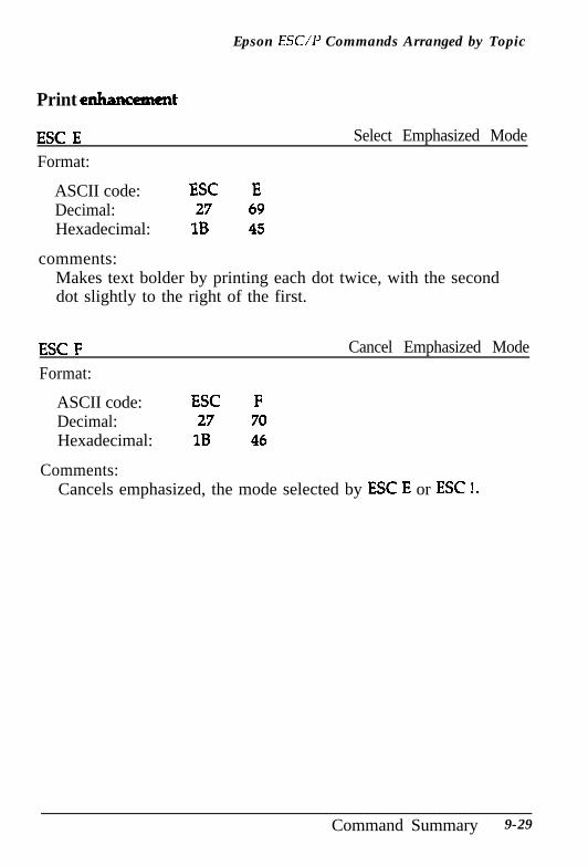
Epson ESC/P Commands Arranged by Topic
Print enhmcmt
ESC EFormat:
Select Emphasized Mode
ASCII code: ESC EDecimal: 27 69Hexadecimal: 1B 45
comments:Makes text bolder by printing each dot twice, with the seconddot slightly to the right of the first.
ESC FFormat:
Cancel Emphasized Mode
ASCII code: ESC FDecimal: 27 70Hexadecimal: 1B 46
Comments:Cancels emphasized, the mode selected by ESC E or ESC I.
Command Summary 9-29
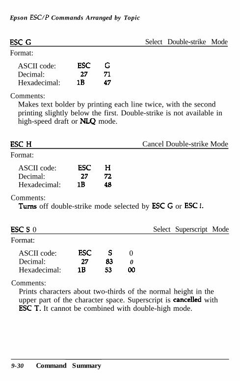
Epson ESUP Commands Arranged by Topic
ESC GFormat:
Select Double-strike Mode
ASCII code: ESC GDecimal: 27 71Hexadecimal: 1B 47
Comments:Makes text bolder by printing each line twice, with the secondprinting slightly below the first. Double-strike is not available inhigh-speed draft or NLQ mode.
ESC H
Format:
ASCII code: ESC HDecimal: 27 72Hexadecimal: 1B 48
Cancel Double-strike Mode
Comments:Turns off double-strike mode selected by ESC G or ESC I.
ESC S 0Format:
Select Superscript Mode
ASCII code: ESC S 0Decimal: 27 83 0Hexadecimal: 1B 53 00
Comments:Prints characters about two-thirds of the normal height in theupper part of the character space. Superscript is cancelled withESC T. It cannot be combined with double-high mode.
9-30 Command Summary
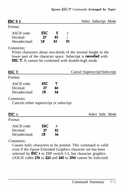
Epson ESUP Commands Arranged by Topic
F!!xSl
Format:
Select Subscript Mode
ASCII code: ESC S 1Decimal: 27 83 1Hexadecimal: 1B 53 01
Comments:Prints characters about two-thirds of the normal height in thelower part of the character space. Subscript is cancelled withESC T. It cannot be combined with double-high mode.
ESC T Cancel Superscript/Subscript
Format:
ASCII code: ESC TDecimal: 27 84Hexadecimal: 1B 54
Comments:Cancels either superscript or subscript.
ESC 4 Select Italic Mode
Format:
ASCII code: ESC 4Decimal: 27 52Hexadecimal: 1B 34
Comments:Causes italic characters to be printed. This command is valideven if the Epson Extended Graphics character set has beenselected by ESC t or DIP switch l-3, but character graphics(ASCII codes 176 to 223 and 240 to 254) cannot be italicized.
Command Summary 9-31
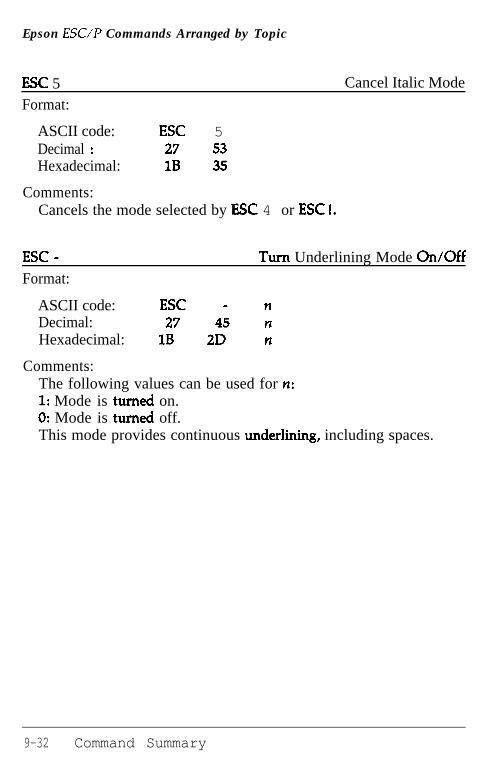
Epson ESC/P Commands Arranged by Topic
ESC 5Format:
Cancel Italic Mode
ASCII code: ESC 5Decimal : 27 53Hexadecimal: 1B 35
Comments:Cancels the mode selected by ESC 4 or ESC I.
ESC -Format:
Turn Underlining Mode On/Off
ASCII code: ESC - nDecimal: 27 45 nHexadecimal: 1B 2D n
Comments:The following values can be used for n:1: Mode is turned on.0: Mode is turned off.This mode provides continuous underlining, including spaces.
9-32 Command Summary
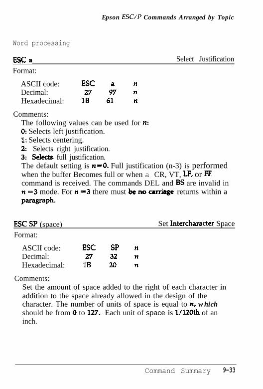
Epson ESUP Commands Arranged by Topic
Word processing
ESCaFormat:
Select Justification
ASCII code: ESC nDecimal: 27 9"7 nHexadecimal: 1B 61 n
Comments:The following values can be used for n:0: Selects left justification.1: Selects centering.2: Selects right justification.3: Select0 full justification.The default setting is n-0. Full justification (n-3) is performedwhen the buffer Becomes full or when a CR, VT, LF, or FFcommand is received. The commands DEL and BS are invalid inn =3 mode. For n =3 there must be m carriage, returns within ax=wwvh.
ESC SP (space)Format:
Set Intercharacter Space
ASCII code: ESC SP nDecimal: 27 32 nHexadecimal: 1B 20 n
Comments:Set the amount of space added to the right of each character inaddition to the space already allowed in the design of thecharacter. The number of units of space is equal to n, whichshould be from 0 to 127. Each unit of space is 1/12Oth of aninch.
Command Summary 9-33
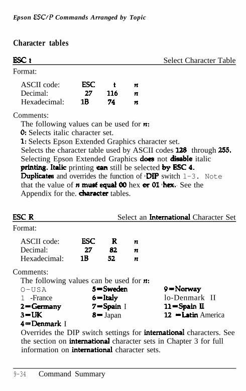
Epson ESC/P Commands Arranged by Topic
Character tables
ESCtFormat:
Select Character Table
ASCII code: ESC t nDecimal: 27 116 nHexadecimal: 1B 74 n
Comments:The following values can be used for tl:0: Selects italic character set.1: Selects Epson Extended Graphics character set.Selects the character table used by ASCII codes 128 through 255.Selecting Epson Extended Graphics does not disable italicprinting. Italic printing ‘can still be selected by ESC 4.Duplicates and overrides the function of pDIP switch l-3. Notethat the value of n must equal 00 hex or 01 heat.. See theAppendix for the. character tables.
ESC RFormat:
Select an International Character Set
ASCII code: ESC R nDecimal: 27 82 nHexadecimal: 1B 52 n
Comments:The following values can be used for n:O-USA S-Sweden 9=Norway1 -France 6-Itdy lo-Denmark II2==Germany 7-Spain I ll--Spain lx3-m 81 Japan 12 *Latin AmericaQ==Denmark IOverrides the DIP switch settings for international characters. Seethe section on international character sets in Chapter 3 for fullinformation on international character sets.
9-34 Command Summary
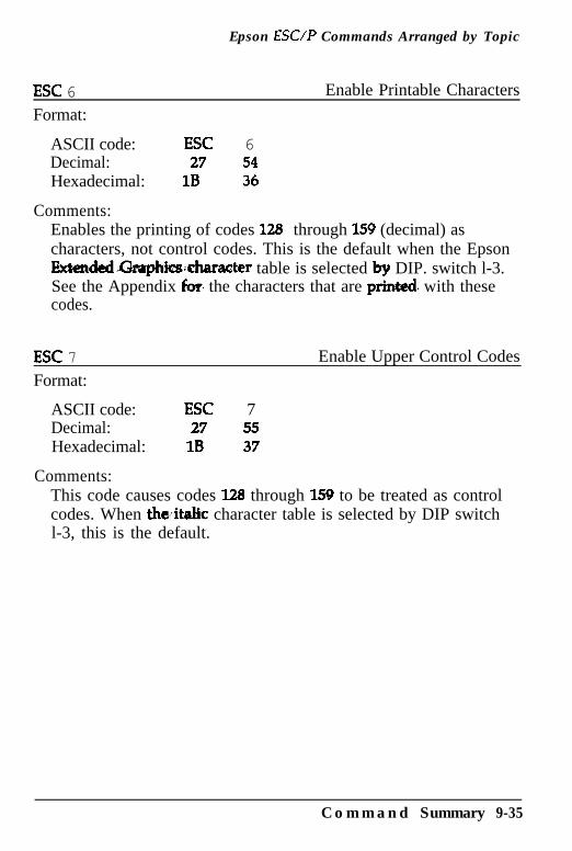
Epson ESUP Commands Arranged by Topic
ESC 6 Enable Printable Characters
Format:
ASCII code: ESC 6Decimal: 27 54Hexadecimal: 1B 36
Comments:Enables the printing of codes 128 through 159 (decimal) ascharacters, not control codes. This is the default when the EpsonExtended.&aphics;character table is selected by DIP. switch l-3.See the Appendix for the characters that are prinkd. with thesecodes.
ESC 7
Format:
Enable Upper Control Codes
ASCII code: ESC 7Decimal: 27 55Hexadecimal: 1B 37
Comments:This code causes codes 128 through 159 to be treated as controlcodes. When theitalic character table is selected by DIP switchl-3, this is the default.
C o m m a n d Summary 9-35
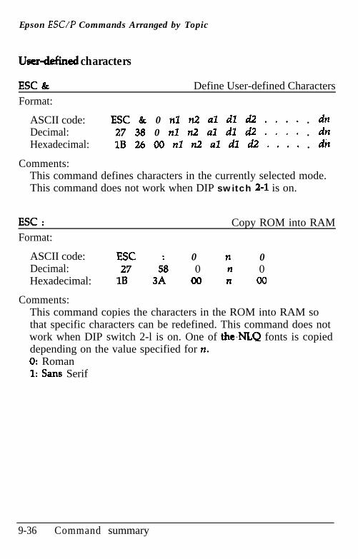
Epson ESC/P Commands Arranged by Topic
Userdefined characters
ESC &Format:
Define User-defined Characters
ASCII code: ESC & 0 nl n2 al dl d2 . . . . . dnDecimal: 27 38 0 nl n2 al dl d2 . . . . . dnHexadecimal: 1B 26 00 nl n2 al dl d2 . . . . . dn
Comments:This command defines characters in the currently selected mode.This command does not work when DIP switch 2-l is on.
ESC :Format:
Copy ROM into RAM
ASCII code: ESC 0 n 0Decimal: 27 5; 0 n 0Hexadecimal: 1B 3A 00 n 00
Comments:This command copies the characters in the ROM into RAM sothat specific characters can be redefined. This command does notwork when DIP switch 2-l is on. One of the,NI.Q fonts is copieddepending on the value specified for n.0: Roman1: Sans Serif
9-36 Command summary
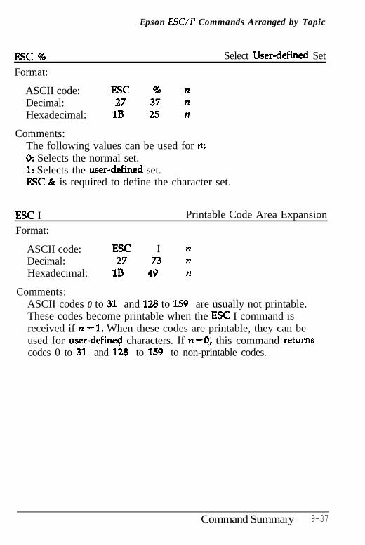
Epson ESUP Commands Arranged by Topic
ESC % Select Userdefined Set
Format:
ASCII code: ESC % nDecimal: 27 37 nHexadecimal: 1B 25 n
Comments:The following values can be used for n:0: Selects the normal set.1: Selects the userddined set.ESC & is required to define the character set.
ESC IFormat:
Printable Code Area Expansion
ASCII code: ESC I nDecimal: 27 73 nHexadecimal: 1B 49 n
Comments:ASCII codes 0 to 31 and 128 to 159 are usually not printable.These codes become printable when the ESC I command isreceived if n -1. When these codes are printable, they can beused for user-defii characters. If n-0; this command returnscodes 0 to 31 and 128 to 159 to non-printable codes.
Command Summary 9-37
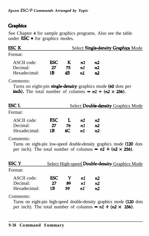
Epson ESC/P Commands Arranged by Topic
See Chapter 4 for sample graphics programs. Also see the tableunder ESC * for graphics modes.
ESC KFormat:
Select Singledensity Graph@ Mode
ASCII code: ESC K nl n2Decimal: 27 75 nl n2Hexadecimal: 1B 4B nl n2
Comments:Turns on eight-pin single-density graphics mode (60 dots perinch). The total number of columns = nl + (n2 x 256).
ESC LFormat:
Select Double-density Graphics Mode
ASCII code: ESC L nl n2Decimal: 27 76 nl n2Hexadecimal: 1B 4C nl n2
Comments:Turns on eight-pin low-speed double-density graphics mode (120 dotsper inch). The total number of columns = ,$1 4 (n2 x 256).
ESC YFormat:
Select High-speed Double-density Graphics Mode
ASCII code: ESC Y nl n2Decimal: 27 89 nl n2Hexadecimal: 1B 59 nl d
Comments:Turns on eight-pin high-speed double-density graphics mode (120 dotsper inch). The total number of columns = nl + (n2 x 256).
9-38 Command Summary
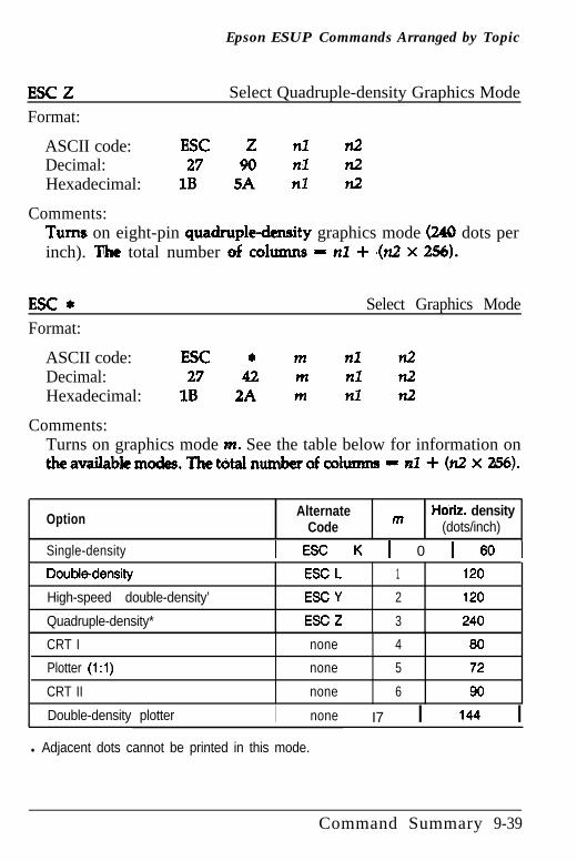
Epson ESUP Commands Arranged by Topic
ESCZFormat:
Select Quadruple-density Graphics Mode
ASCII code: ESC Z nl n2Decimal: 27 90 nl d!Hexadecimal: 1B 5A nl n2
Comments:Turns on eight-pin quadruple-density graphics mode (240 dots perinch). The total number of ~01~s - nl + -(n2 X 256).
Esc*
Format:Select Graphics Mode
ASCII code: ESC * m nl n2Decimal: 27 42 m nl n2Hexadecimal: 1B 2A m nl n2
Comments:Turns on graphics mode PL See the table below for information ontheavaiIablemodes.Thetotalnumberofcolunns - nl+ (n2 x 256).
Option AlternateCode
Horiz. densitym (dots/inch)
Single-density 1 ESC K 1 0 1 60 1
Double-density ESC L 1 120
High-speed double-density’ ESC Y 2 120
Quadruple-density* ESC Z 3 240
CRT I none 4 80
Plotter (1: 1) none 5 72
CRT II none 6 90
Double-density plotter I none I7 I 144 Il Adjacent dots cannot be printed in this mode.
Command Summary 9-39
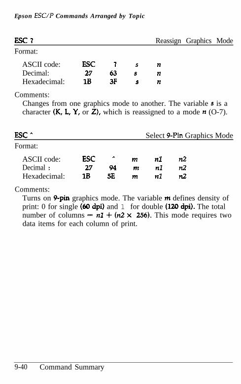
Epson ESC/P Commands Arranged by Topic
ESC?Format:
Reassign Graphics Mode
ASCII code: ESC 1 s nDecimal: 27 63 s nHexadecimal: 1B 3F s n
Comments:Changes from one graphics mode to another. The variable s is acharacter (K, L, Y, or Z), which is reassigned to a mode n (O-7).
EsC^
Format:Select g-Pin Graphics Mode
ASCII code: ESC A m nl n2Decimal : 27 94 m nl n2Hexadecimal: 1B 5E m nl n2
Comments:Turns on g-pin graphics mode. The variable m defines density ofprint: 0 for single (60 dpi) and 1 for double (120 dpi). The totalnumber of columns = nl + (n.2 x 256). This mode requires twodata items for each column of print.
9-40 Command Summary
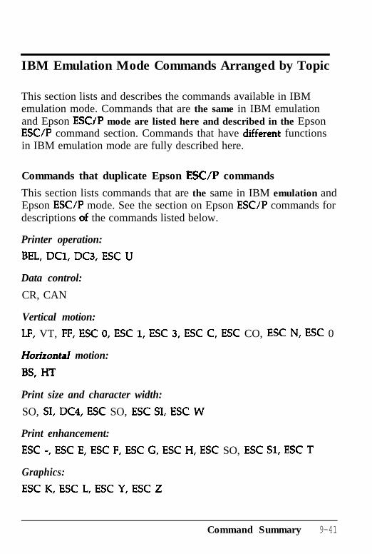
IBM Emulation Mode Commands Arranged by Topic
This section lists and describes the commands available in IBMemulation mode. Commands that are the same in IBM emulationand Epson ESCJP mode are listed here and described in the EpsonESC/P command section. Commands that have different functionsin IBM emulation mode are fully described here.
Commands that duplicate Epson ESUP commands
This section lists commands that are the same in IBM emulation andEpson ESC/P mode. See the section on Epson ESC/P commands fordescriptions uf the commands listed below.
Printer operation:
BEL, DCl, DC3, ESC U
Data control:
CR, CAN
Vertical motion:
LF, VT, FF, ESC 0, ESC 1, ESC 3, ESC C, ESC CO, ESC N, ESC 0
Horizontal motion:
BS, HT
Print size and character width:
SO, SI, DC4, ESC SO, ESC SI, ESC W
Print enhancement:
ESC -, ESC E, ESC F, ESC G, ESC H, ESC SO, ESC Sl, ESC T
Graphics:
ESC K, ESC L, ESC Y, ESC Z
Command Summary 9-41
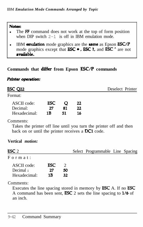
IBM Emulation Mode Commands Arranged by Topic
Nutts:l The FF command does not work at the top of form position
when DIP switch 2-l is off in IBM emulation mode.
l IBM emulation mode graphics are the ,same as Epson ESC/Pmode graphics except that ESC * , ESC 7, and ESC A are notamdablt.
Commands that differ from Epson ,ESC/P commands
Rinttr ojrwation:
ESC Q22 Deselect Printer
Format:
ASCII code: ESC Q 22Decimal: 27 81 22Hexadecimal: 1B 51 16
Comments:Takes the printer off line until you turn the printer off and thenback on or until the printer receives a DC1 code.
Vertical motion:
ESC 2 Select Programmable Line SpacingF o r m a t :
ASCII code: ESC 2Decimal : 27 50Hexadecimal: 1B 32
Comments:Executes the line spacing stored in memory by ESC A. If no ESCA command has been sent, ESC 2 sets the line spacing to l/6 ofan inch.
9-42 Command Summary
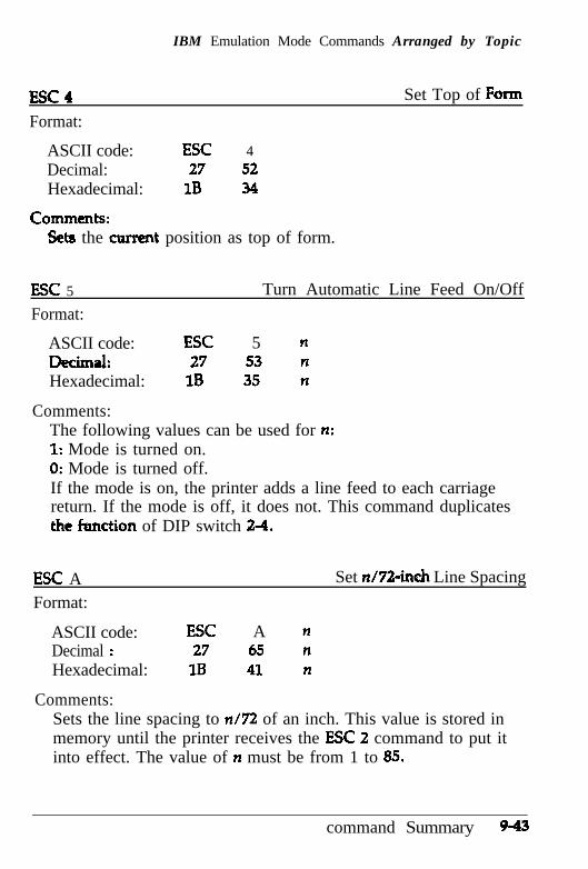
IBM Emulation Mode Commands Arranged by Topic
Escr
Format:
ASCII code: ESC 4Decimal: 27 52Hexadecimal: 1B 34
Set Top of Form
Comments:Sets the current position as top of form.
ESC 5
Format:
Turn Automatic Line Feed On/Off
ASCII code: ESC 5 nDE!CiUd: 27 53 nHexadecimal: 1B 35 n
Comments:The following values can be used for n:1: Mode is turned on.0: Mode is turned off.If the mode is on, the printer adds a line feed to each carriagereturn. If the mode is off, it does not. This command duplicatesthe hction of DIP switch 2-4.
ESC AFormat:
Set n/72-inch Line Spacing
ASCII code: ESC A nDecimal : 27 65 nHexadecimal: 1B 41 n
Comments:Sets the line spacing to n/72 of an inch. This value is stored inmemory until the printer receives the ESC 2 command to put itinto effect. The value of n must be from 1 to 85.
command Summary 9-43
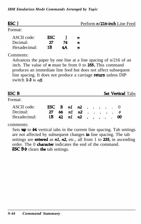
IBM Emulation Mode Commands Arranged by Topic
ESC JFormat:
Perform n/216-inch Line Feed
ASCII code: ESC J nDecimal: 27 74 nHexadecimal: 1B 4A n
Comments:Advances the paper by one line at a line spacing of n/216 of aninch. The value of n must be from 0 to 255. This commandproduces an immediate line feed but does not affect subsequentline spacing. It does not produce a carriage return unless DIPswitch 13 is off.
ESC B Set Vertical TabsFormat:
ASCII code:Decimal:Hexadecimal:
comments:
ESC B nl n2 . . . . . 027 66 nl n2 . . . . . 01B 42 nl n2 . . . . . 00
Sets up to 64 vertical tabs in the current line spacing. Tab settingsare not affected by subsequent changes in line spacing. The tabsettings are entered as nl, n2, etc., all from 1 to 255, in ascendingorder. The 0 character indicates the end of the command.ESC BO clears the tab settings.
9-44 Command Summary
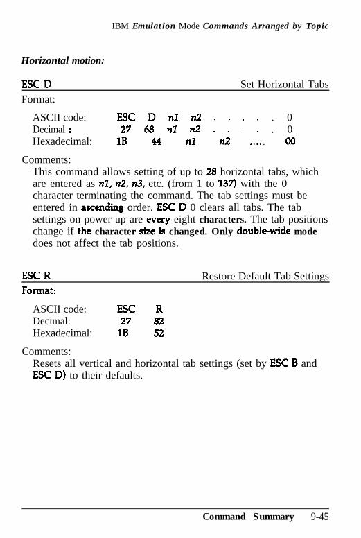
IBM Emulation Mode Commands Arranged by Topic
Horizontal motion:
ESC D Set Horizontal TabsFormat:
ASCII code: ESC D nl n2 . . . . . 0Decimal : 27 68 nl n2 . . . . . 0Hexadecimal: 1B 44 nl n2 . . . . . 00
Comments:This command allows setting of up to 28 horizontal tabs, whichare entered as nl, n2, n3, etc. (from 1 to 137) with the 0character terminating the command. The tab settings must beentered in ascending order. ESC D 0 clears all tabs. The tabsettings on power up are every eight characters. The tab positionschange if the character sizt is changed. Only double-wide modedoes not affect the tab positions.
ESC R Restore Default Tab Settings
ASCII code: ESC RDecimal: 27 82Hexadecimal: 1B 52
Comments:Resets all vertical and horizontal tab settings (set by ESC B andESC D) to their defaults.
Command Summary 9-45
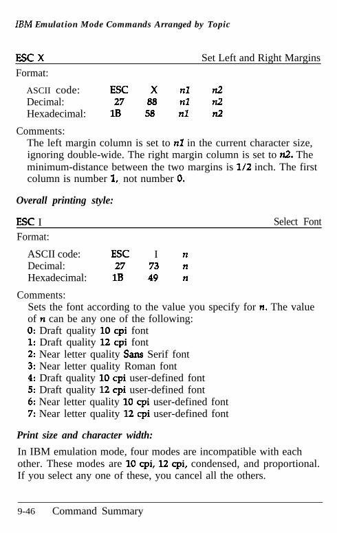
IBM Emulation Mode Commands Arranged by Topic
ESC XFormat:
Set Left and Right Margins
ASCII code: ESC X nl n2Decimal: 27 88 nl n2Hexadecimal: 1B 58 n7 n2
Comments:The left margin column is set to n3 in the current character size,ignoring double-wide. The right margin column is set to n2. Theminimum-distance between the two margins is l/2 inch. The firstcolumn is number 1,. not number 0.
Overall printing style:
ESC IFormat:
Select Font
ASCII code: ESC I nDecimal: 27 73 nHexadecimal: 1B 49 n
Comments:Sets the font according to the value you specify for n. The valueof n can be any one of the following:0: Draft quality 10 cpi font1: Draft quality 12 cpi font2: Near letter quality Sans Serif font3: Near letter quality Roman font4: Draft quality 10 cpi user-defined font5: Draft quality 12 cpi user-defined font6: Near letter quality 10 cpi user-defined font7: Near letter quality 12 cpi user-defined font
Print size and character width:
In IBM emulation mode, four modes are incompatible with eachother. These modes are 10 cpi, 12 cpi, condensed, and proportional.If you select any one of these, you cancel all the others.
9-46 Command Summary
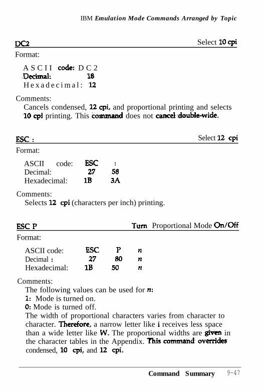
IBM Emulation Mode Commands Arranged by Topic
Format:
Select 10 cpi
A S C I I code: D C 2.Decimal: 18H e x a d e c i m a l : 12
Comments:Cancels condensed, 1.2 cpi, and proportional printing and selects10 cpi printing. This command does not eancekdouble-wide.
ESC : Select 12 cpi
Format:
ASCII code: ESCDecimal: 27 5;Hexadecimal: 1B 3A
Comments:Selects 12 cpi (characters per inch) printing.
ESC PFormat:
Turn Proportional Mode On/Off
ASCII code: ESC P nDecimal : 27 80 nHexadecimal: 1B 50 n
Comments:The following values can be used for n:1: Mode is turned on.0: Mode is turned off.The width of proportional characters varies from character tocharacter. Therefore, a narrow letter like i receives less spacethan a wide letter like W. The proportional widths are given inthe character tables in the Appendix. This command, ovtrridtscondensed, 10 cpi, and 12 cpi.
Command Summary 9-47
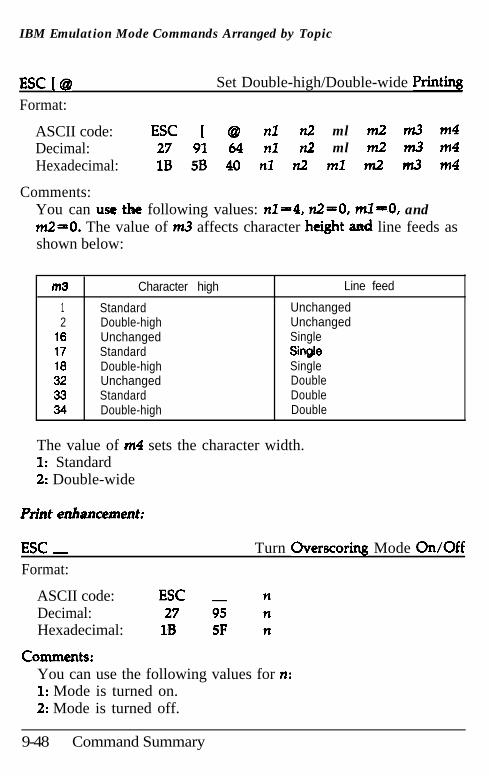
IBM Emulation Mode Commands Arranged by Topic
ESC [@it’Format:
Set Double-high/Double-wide Print%
ASCII code: ESC [ @ nl n2 ml m2 m3 m4Decimal: 27 91 64 nl n2 ml m2 m3 m4Hexadecimal: 1B 5B 40 nl n2 ml m2 m3 m4
Comments:You can use the following values: n1=4, nZ=O, ml-O, andm2=0. The value of m.3 affects character height and line feeds asshown below:
m3 Character high Line feed
1 Standard Unchanged2 Double-high Unchanged
16 Unchanged Single17 Standard Single16 Double-high Single32 Unchanged Double33 Standard Double34 Double-high Double
The value of m4 sets the character width.1: Standard2: Double-wide
Print enhancement:
ESC _ Turn Overscoring Mode On/OffFormat:
ASCII code: ESC nDecimal: 27 95 nHexadecimal: 1B 5F n
commtnts:You can use the following values for n:1: Mode is turned on.2: Mode is turned off.
9-48 Command Summary
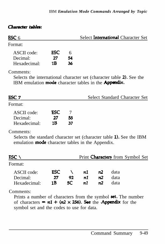
IBM Emulation Mode Commands Arranged by Topic
Clmradtr tables:
ESC 6Format:
Select International Character Set
ASCII code: ESC 6Decimal: 27 54Hexadecimal: 1B 36
Comments:Selects the international character set (character table 2). See theIBM emulation mode character tables in the Apm.
ESC 7Format:
Select Standard Character Set
ASCII code: ESC 7Decimal: 27 55Hexadecimal: 1B 37
Comments:Selects the standard character set (character table 1). See the IBMemulation mode character tables in the Appendix.
ESC \Format:
Print CharacFers from Symbol Set
ASCII code: ESC \ nl n2 dataDecimal: 27 92 nl ?12 dataHexadecimal: 1B 5C nl n2 data
Comments:Prints a number of characters from the symbol set. The numberof characters - nl + (n2 x 256). See the :&qtdix for thesymbol set and the codes to use for data.
Command Summary 9-49
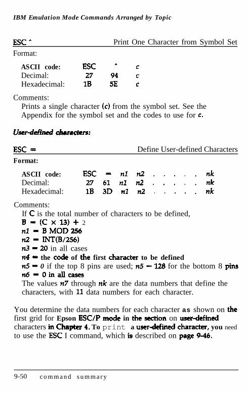
IBM Emulation Mode Commands Arranged by Topic
ESC AFormat:
Print One Character from Symbol Set
ASCII code: ESC A cDecimal: 27 94 cHexadecimal: 1B 5E c
Comments:Prints a single character (c) from the symbol set. See theAppendix for the symbol set and the codes to use for c.
ESC =Format:
Define User-defined Characters
ASCII code:Decimal:Hexadecimal:
Comments:
ESC = nl n2 . . . . . nk27 61 nl n2 . . . . . nk1B 3D nl n2 . . . . . nk
If C is the total number of characters to be defined,B - (C x 13) + 2nl = BMOD256n2= INT(B/256)n3 = 20 in all casesn4 = the codt of the first character to be definedn5 = 0 if the top 8 pins are used; n5 = 128 for the bottom 8 @nsn6==OinallcasesThe values n7 through nk are the data numbers that define thecharacters, with 11 data numbers for each character.
You determine the data numbers for each character as shown on thefirst grid for Epson ESUP mode in tht section on ustrdtfimdcharacters irt Chqttr 4. To print a user-defined character, you needto use the ESC I command, which is described on page 9-46.
9-50 c o m m a n d s u m m a r y
Appendix
Proportional Width Table .......................................... A-2
Character Tables ...................................................... A-6Italic character table ............................................... A-7Epson Extended Graphics character table.................... A-8IBM emulation ‘mode .............................................. A-9
Append ix A- l
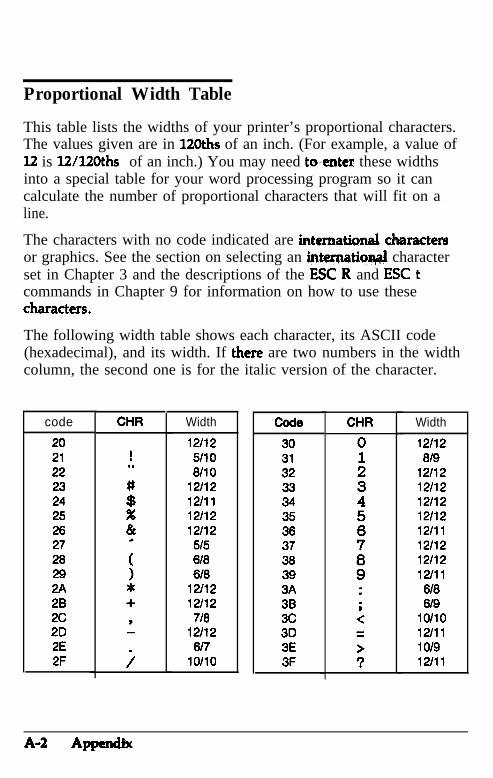
Proportional Width Table
This table lists the widths of your printer’s proportional characters.The values given are in 12Oths of an inch. (For example, a value of12 is 12/12Oths of an inch.) You may need toenter these widthsinto a special table for your word processing program so it cancalculate the number of proportional characters that will fit on aline.
The characters with no code indicated are internationel chnractersor graphics. See the section on selecting an internatioq6jl characterset in Chapter 3 and the descriptions of the ESC R and ESC tcommands in Chapter 9 for information on how to use thesecharacters.
The following width table shows each character, its ASCII code(hexadecimal), and its width. If there are two numbers in the widthcolumn, the second one is for the italic version of the character.
code CHR Width code CHR Width
202122232425262726292A282c202E2F
12112 305110 316110 32
12112 3312/11 3412112 3512112 36
515 37618 38610 39
12./12 3A12i12 36
718 3c12/12 30
6/7 3ElO/lO 3F
12112at9
1211212l121211212/1212/11121121211212111
618619
lo/lo12/11101912/11
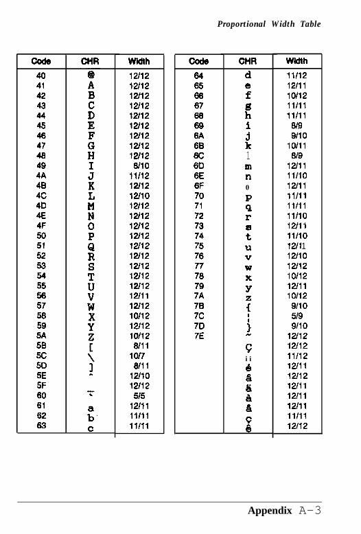
Proportional Width Table
404142434445464746494A484c4D4E4F5051525354
25756595A5B5c505E5F60616263
Width12/12la1212t1212t1212t12121121211212t1212t12
811011t1212t1212t1012t1212112121121211212t1212t1212t1212t1212t1212t1112t121011212t121ot126tll
lot7Wll
12tlO12t12
5t512t1111t1111111
6465666766696A
ii6D6E6F707172737475767776797A787c707E
CHR
d8f
hB.
;k1mn0
:r
:UVWX
Y
s
j
ci iBa
t
:
cQ
Width
1111212t111ot121111111111
6t99110
lO/ll6t9
12tllll/lO12/111101ll/ll111101211111t1012/l 11211012t12101121211110/12
91105199110
12t1212tl211/1212tll12t121211112111121111111112/12
Appendix A-3
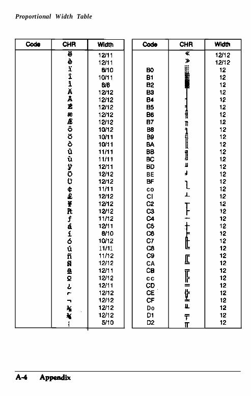
Proportional Width Table
12tll12tllWlO
10111W6
1211212t12120212t1212t12lWl2lo/11lo/l1ll/ll11t111211112112121121111112t1212t121211211t12121116tlO
1ot121 l/l 11111212t1212tll12tl212tll12t1212t1212tl212/125tlO
Bo8182a384B5a687a6BSBABBBcBDBEBFcoClc2c3CMc5c6c7c6c9CACBccCD.CECFDoDl02
wii12tl212t12
12121212121212121212T2121212121212121212121212121212121212121212121212
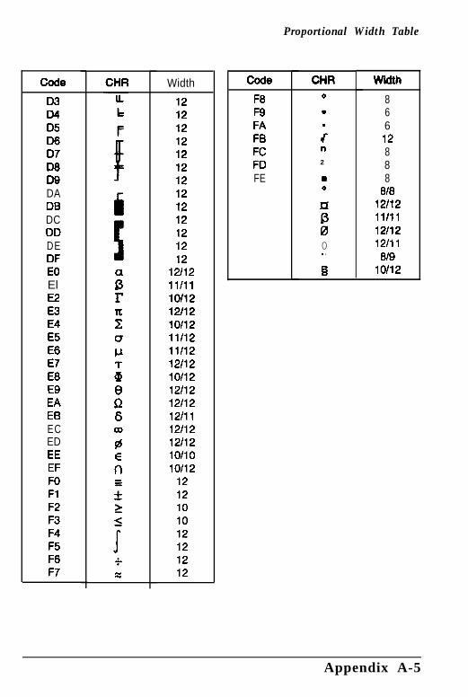
Proportional Width Table
Code
D3D4D5D607D8DQDADBDCDDDEDFEOElE2E3E4E5E6E7E8EQEAEBECEDEEEFFOFlF2F3F4F5F6F7
Width
12121212121212121212121212
12112ll/ll10112121121011211/12111121211210112121121211212/1112/1212/12lo/lo10/12
1212101012121212
F8FQFAFBFCFDFE
CHR0
.
;n2
20
r2
ii
0. .
Q
width
86612888
8f812f12llfll12f1212fll
819lOf12
Appendix A-5
Character Tables
You can select the character tables in this section by setting DIPswitch 1-3 or using the ESC t software command.
In the tables, the first digit of each hex code is in the top row andthe second digit is in the first column. The binary digits are in thesecond row and second column, and the decimal codes are in therectangle next to the character. For example, for an uppercase A,the hex code is 41, the binary code is 01000001, and the decimalcode is 65.
Note: The printer can print the characters in the shaded areasonly if you send the ESC 6 command to the printer. If you donot send the ESC 6 command, the shaded areas contain thecontrol codes in the range of 0 to 31 and 127.
A-6 Appendix
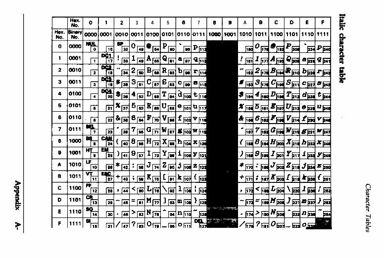
12 3 4 5 0 7 8.9 A B C D E F
oool 0010 0011 0100 0101 0110 0111 loo0 1001 1010 1011 1100 1101 1110 t111
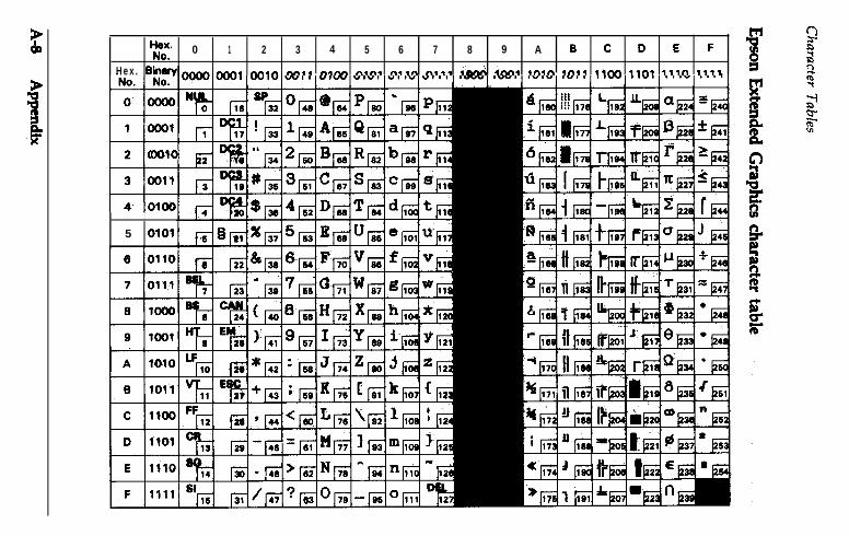
‘$c 0 1 2 3 4 5 6 7 8 9 A B C D E F
Hex. -. M.A An.. A.M n.n. n.,n n-4* iMA iM, ,fi,rl ,fi,, ,3M ,rnr ,t,n ,,,,
0 oooo’ ”
1 oool ,rn
~
2 0010 3 D(
30011 p
40100 /I
5 0101
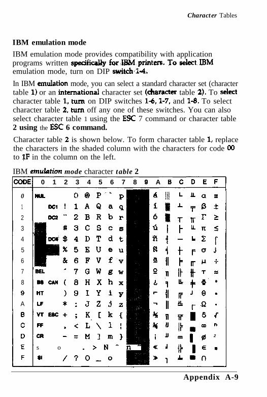
Character Tables
IBM emulation modeIBM emulation mode provides compatibility with applicationprograms written spe&ca& forIB.M.printers. To seIect.IBMemulation mode, turn on DIP switch:1-4.
In IBM emu&ion mode, you can select a standard character set (charactertable 1) or an international character set (character table a). To sektcharacter table 1, turn on DIP switches l-6, 1-7, and l-8. To selectcharacter table 2, turn off any one of these switches. You can alsoselect character table 1 using the EE 7 command or character table2 using the ESC 6 command.
Character table 2 is shown below. To form character table 1, replacethe characters in the shaded column with the characters for code 00to $F in the column on the left.
IBM emu&Am mode character table 2;ODEf 0 1 2 3 4 5 6 7 8 9 A B C D E F
0 NUL 0 @ P-‘ p1 DC1 ! 1AQaq2 DC2 ” 2BRbr3
4
5
6
7
8
Q
A
B
C
D
E
F
#3CScs$4DTdt%5EWeu&6FVfv
.BEL -7GWgwBsrs(8HXhxHT )SIYiyLF * : JZJxvTEsc+; K. C k CFF I <L\ 11CM - =Mlm)s o .>N^n-
81 /?O,o
J.-r
x0
.
J
n
2
Appendix A-9
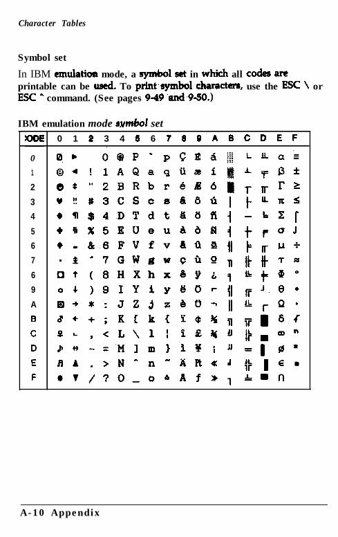
Character Tables
Symbol set
In IBM emulatiaa mode, a symbol s& in which all codes areprintable can be used. To prlnt’symbol character, use the ESC \ orESC A command. (See pages 9-49 ‘d~9-5D.)
IBM emulation mode swdd set
0
1
2
3
4
5
6
7
6
9
A
B
C
D
E
F
0 1 2 3 4 6 6 t 8 9’A B C D E F
A-10 Appendix
Glossary
The following definitions apply specifically to printers.
application programA wftware program that helps you carry out a particular task, suchas word processing or financial planning.
ASCIIAmerican Standard Code for Information Interchange. Astandardized coding system for assigning numerical codes to lettersand symbols.
auto line feedWhen this feature is selected using a DIP switch, each carriagereturn code (CR) is automatically followed by a line feed (LP) code.
baud rateA measure of the speed of data transmission. Usually expressed inbits per second (bps).
bidirectional printingPrinting in which the print head moves from left to right on everyother line and from right to left on the others. This increases theprinting speed.
binarySee number systems.
bitA binary digit (0 or 11, which is the smallest unit of informationused by a printer or computer. See a2so number systems.
Glossary GL-1
bufferSee memory.
byteA unit of information consisting of eight bits.
carriage returnThe control code that returns the print position to the left margin.When issued together with a line feed, the print positi moves tothe left margin of the next line. (In bidirectional printing, the printhead does not always move to the left margin.)
character setA collection of letters, numbers, and symbols that provides youwith the characters used in a particular language.
character table IA portion of the printer’s standard ASCII character set that can beused for graphic symbols or italic characters. See also EpsonExtended Graphics character table and italic.
characters per inch (cpi)A measure of the size of text characters. 10 cpi is the printer’sdefault setting.
condensedPrinting in which each character is approximately 60% of the widthof standard characters. Condensed printing is useful when printingwide tables or spreadsheets.
continuous paperPaper that has sprocket-feed holes on each side, is perforatedbetween pages, and comes in a folded stack. Also called fanfoldpaper.
GL-2 G l o s s a r y
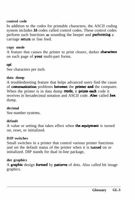
control codeIn addition to the codes for printable characters, the ASCII codingsystem includes 33 codes called control codes. These control codesperform such functions as sounding the beeper and performing acarriage return or line feed.
copy modeA feature that causes the printer to print clearer, darker characterson each page of your multi-part forms.
cpiSee characters per inch.
data dumpA troubleshooting feature that helps advanced users find the causeof communication problems between the pxintex and the computer.When the printer is in data dump mode, it printseach code itreceives in hexadecimal notation and ASCII code. Also called .hexdump.
decimalSee number systems.
defaultA value or setting that takes effect when theequipment is turnedon, reset, or initialized.
DIP switchesSmall switches in a printer that control various printer functionsand set the default status of the printer when it is turned on orinitialized. DIP stands for dual in-line package,
dot graphicsA graphic design formed by patterns of dots. Also called bit imagegraphics.
Glossary GL-3
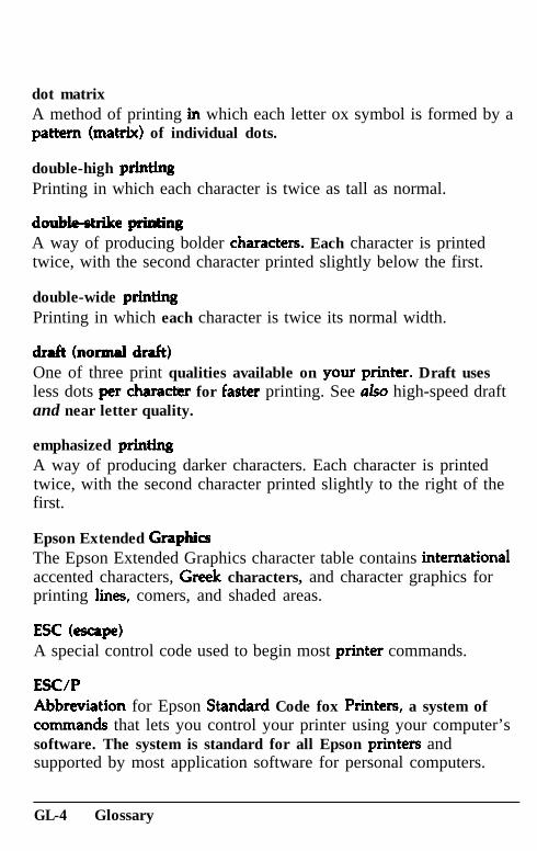
dot matrixA method of printing in which each letter ox symbol is formed by apattern (matrix) of individual dots.
double-high printingPrinting in which each character is twice as tall as normal.
double-&x&e pai&ingA way of producing bolder characters. Each character is printedtwice, with the second character printed slightly below the first.
double-wide pxintingPrinting in which each character is twice its normal width.
draft (noxmal draft)One of three print qualities available on your printer. Draft usesless dots per charactex for faster printing. See also high-speed draftand near letter quality.
emphasized printingA way of producing darker characters. Each character is printedtwice, with the second character printed slightly to the right of thefirst.
Epson Extended Gxaphkr~The Epson Extended Graphics character table contains internationalaccented characters, Greek characters, and character graphics forprinting lines, comers, and shaded areas.
ESC b-q4A special control code used to begin most printer commands.
ESC/PAbbreviation for Epson Standard Code fox Printers, a system ofcommands that lets you control your printer using your computer’ssoftware. The system is standard for all Epson printers andsupported by most application software for personal computers.
GL-4 Glossary
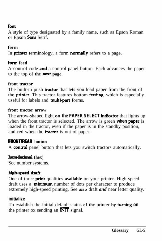
A style of type designated by a family name, such as Epson Romanor Epson Sans Serif.
formIn pxintex terminology, a form normally refers to a page.
form feedA control code and a control panel button. Each advances the paperto the top of the next page.
front tractorThe built-in push tractor that lets you load paper from the front ofthe printer. This tractor features bottom feedmg, which is especiallyuseful for labels and ~multi-part forms.
front tractor arrowThe arrow-shaped light on the PAPER SELECT indicator that lights upwhen the front tractor is selected. The arrow is green when paper isloaded in the tractor, even if the paper is in the standby position,and red when the tractor is out of paper.
FRONT/REAR buttonA control panel button that lets you switch tractors automatically.
hexadedmal (hex)See number systems.
high-spe!ed draftOne of three print qualities available on your printer. High-speeddraft uses a ~minimum number of dots per character to produceextremely high-speed printing. See also draft and near letter quality.
initializeTo establish the initial default status of the printer by turning onthe printer ox sending an INIT signal.
Glossary GL-5
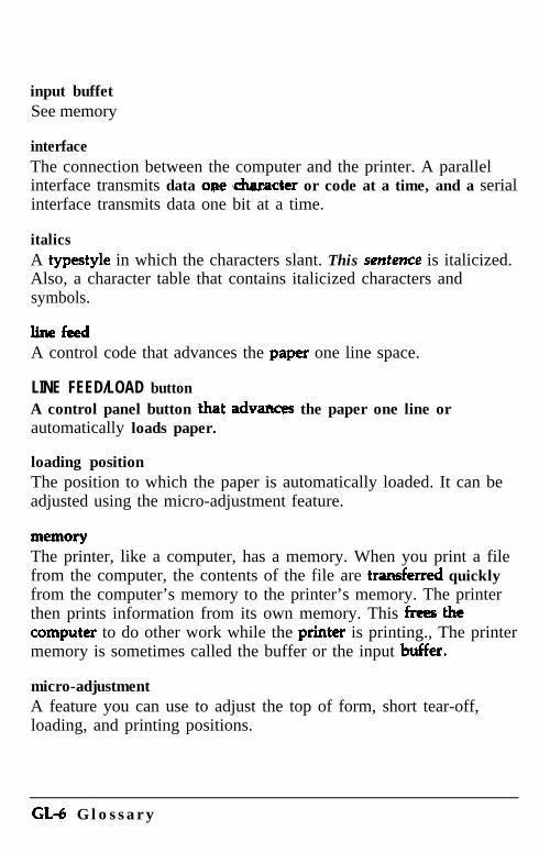
input buffetSee memory
interfaceThe connection between the computer and the printer. A parallelinterface transmits data we character or code at a time, and a serialinterface transmits data one bit at a time.
italicsA typestyle in which the characters slant. This sentence is italicized.Also, a character table that contains italicized characters andsymbols.
linefeedA control code that advances the paper one line space.
LINE FEED/LOAD buttonA control panel button .that advax~~~ the paper one line orautomatically loads paper.
loading positionThe position to which the paper is automatically loaded. It can beadjusted using the micro-adjustment feature.
The printer, like a computer, has a memory. When you print a filefrom the computer, the contents of the file are transferred quicklyfrom the computer’s memory to the printer’s memory. The printerthen prints information from its own memory. This frees thecomputer to do other work while the printer is printing., The printermemory is sometimes called the buffer or the input buffer.
micro-adjustmentA feature you can use to adjust the top of form, short tear-off,loading, and printing positions.
GL-6 G l o s s a r y
near letter quality (NLQ)One of three print qualities available on your printer. Near letterquality reduces !the print speed and increases the number of dots percharacter to produce high-resolution characters. See also draft andhigh-speed draft.
number systemsThree number systems are commonly used with printers:
Decimal is base 10 and uses the digits 0 through 9. (This is themost familiar system.)
Hexadecimal (hex) is base 16 and uses the ‘digits 0 through 9 andthe letters A through F. Programmers frequently use thisnumbering system. Any decimal number between 0 and 255 can
’ be expressed by a two-digit hex number.
Binary is base 2 and uses only the digits 0 and 1. All infoxmationin computer systems is handled in binary form to representelectrical signals that are on or off. A binary digit is often calleda bit; any decimal number been 0 and 255 can be expressedby an eight-bit binary number.
on lineWhen the printer is on line, it can communicate with the computerconnected to it; The ON LINE button controls the printer’s online/off line status.
paper bailThe part of the printer that holds the paper flat.
paper cutterAn optional device that automatically cuts off printed documents.
paper memoryA feature that produces high quality printing on your multi-partforms by usmg stored paper foxmat and thiclmess information toadjust the print head.
Glossary GL-7
papemwt sensorA small switch on the tractors that sends a signal when it is not incontact with paper, causing the PAPER OUT light to go on.
papex select indicatorThe printer icon on the control panel that contains the front andrear tractor arrows. These arrows light up to show which tractor isselected. See also front’ txactoi arrow and rear tractor arrow.
parallel interfaceA type of connection between the computer and the printer. Aparallel interface transmits data one character ox code at a time.
A method for a computer and printer to check the reliability of datatransmission.
platenThe silver plate behind the paper bail that provides a backing foxthe printing.
Your printer has three types of print quality: draft, high-speeddraft, and neax letter quality (NLQ). Draft and high-speed draft axefor high-speed, draft-quality jobs; NLQ is for final, polisheddocuments.
proportional printingPrinting in which the amount of space given to each charactervaries. For example, an uppercase W receives much more space thana lowercase .i. The result looks more like a typeset book than atypewritten draft.
pull tractorAn optional paper feeder that is useful when printing on preprintedox multi-part forms.
GL-8 G l o s s a r y
push tractorA device that feeds continuous paper through the printer. Both thefront and rear built-in tractors are push tractors; they push thepaper through the printer to the print head.
Random Access Memory. The portion of the printer’s memory thatis used as a buffer and as a place for storing userdefined characters.
rear tractorThe built-in push tractor that feeds paper from the rear of theprinter.
rear tractor arrowThe arrow-shaped light on the PAPER SELECT indicator that lights upwhen the rear tractor is selected. The arrow is green when paper isloaded in the tractor, even if the paper is in the standby position,and red when the tractor is out of paper.
resetTo return a printer to its defaults by sending a command or anINIT signal or by turning the printer off and then back on.
self testA method of checking the operation of the printer. When the selftest is run, the printer prints its current DIP switch settings and thecharacters that are stored in its ROM (Read Only Memory).
serial interfaceA type of connection between the computer and the printer. Aserial interface transmits data one bit at a time.
short tear-offA feature that feeds the paper’s perforation to the tear-off positionand then feeds the paper back to the loading position. You canchange the tear-off position using the micro-adjustment feature.
Glossary GL-9
standby positionThe position the paper is in after you manually load it onto the firstfew pins of the tractor sprockets. When the printer switchestractors, it feeds the paper on the previously selected tractor back tothis position.
subscriptsPrinting in which each character is printed at about two-thirds thenormal height in the lower part of the character space.
superscriptsPrinting in which each character is printed at about two-thirds thenormal height in the upper part of the character space.
10 cpiA character spacing with 10 characters per inch. This is the printer’sdefault character spacing.
TEAR OFF buttonA button that lets you use the short tear-off feature. See shorttear-off.
tear-off positionThe position the printer feeds the paper to when you press the TEAROFF button. Using the micro-adjustment feature, you can adjust thisposition so that the paper’s perforation meets the printer’s tear-off edge.
top of form positionThe position on the paper that the printer recognizes as the firstprintable line. The printer feeds the paper to this position when itloads the paper. You can change this position using the micro-adjustment feature.
tractorThe part of the printer that feeds continuous paper through theprinter by gripping the holes along the paper’s sides.
GL-10 Glossary
12 cpiA character spacing in which each character is slightly narrowerthan normal, so that there arc 12 characters per inch.
unidirectional printingPrinting in one direction only. Unidirectional printing is useful forprinting graphics because it allows more precise vertical alignmentthan bidirectional printing.
userdefined charactersCharacters that are defined and stored in the printer by the user.Also known as download characters.
Glossary GL-11
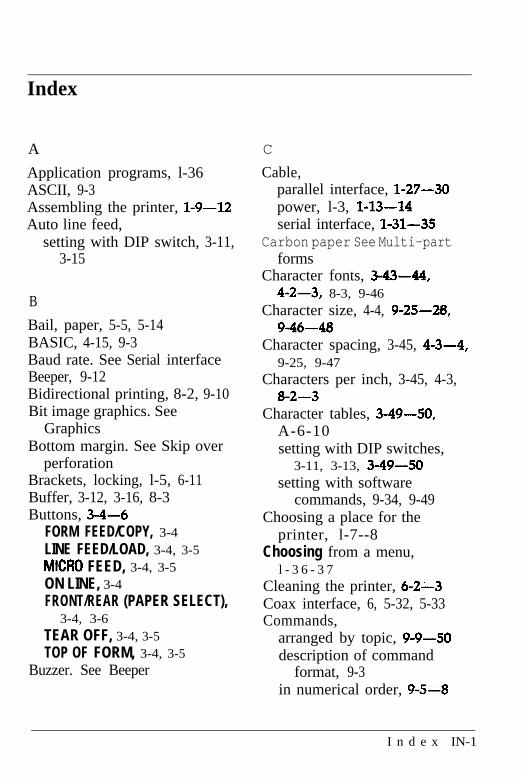
Index
A
Application programs, l-36ASCII, 9-3Assembling the printer, l-9-12Auto line feed,
setting with DIP switch, 3-11,3-15
B
Bail, paper, 5-5, 5-14BASIC, 4-15, 9-3Baud rate. See Serial interfaceBeeper, 9-12Bidirectional printing, 8-2, 9-10Bit image graphics. See
GraphicsBottom margin. See Skip over
perforationBrackets, locking, l-5, 6-11Buffer, 3-12, 3-16, 8-3Buttons, 3-4-6
FORM FEED/COPY, 3-4LINE FEED/LOAD, 3-4, 3-5MM0 FEED, 3-4, 3-5ON LINE, 3-4FRONT/REAR (PAPER SELECT),
3-4, 3-6TEAR OFF, 3-4, 3-5TOP OF FORM, 3-4, 3-5
Buzzer. See Beeper
C
Cable,parallel interface, l-27-30power, l-3, l-13-14serial interface, 1-31-35
Carbon paper See Multi-partforms
Character fonts, 3-43-44,4-2-3, 8-3, 9-46
Character size, 4-4, 9-25--28,9-46-48
Character spacing, 3-45, 4-3-4,9-25, 9-47
Characters per inch, 3-45, 4-3,8-2-3
Character tables, 349-50,A-6-10setting with DIP switches,
3-11, 3-13, 3-49-50setting with software
commands, 9-34, 9-49Choosing a place for the
printer, l-7--8Choosing from a menu,
l - 3 6 - 3 7Cleaning the printer, 6-2-3Coax interface, 6, 5-32, 5-33Commands,
arranged by topic, 9-9-50description of command
format, 9-3in numerical order, 9-5-8
I n d e x IN-1
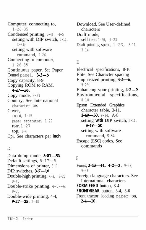
Computer, connecting to,l-26-35
Condensed printing, 3-46, 4-5setting with DIP switch, 3-11,
3-46setting with software
command, 9-26Connecting to computer,l-26-35
Continuous paper. See PaperControl panel, 3-2-6Copy capacity, 8-9Copying ROM to RAM,
4-27-28 Copy mode, 2-29Country. See International
character setsCover,
front, 1-15paper separator, l-22rear, l-27top, 1-4
Cpi. See characters per inch
D
Data dump mode, 3-51-53Default settings, 8-17--8Dimensions of printer, 8-9DIP switches, 3-7-16Double-high printing, 4-4, 9-28,
9-48Double-strike printing, 4-5--6,
9-30Double-wide printing, 4-4,
9-27-20, 9-48
Download. See User-definedcharacters
Draft mode,self test, 1-20, l-23
Draft printing speed, l-23, 3-11,3-14
E
Electrical specifications, 8-10Elite. See Character spacingEmphasized printing, 4-5-6,
9-29Enhancing your printing, 4-2-9Environmental specifications,
8-10Epson Extended Graphics
character table, 3-11,3-49-50, 9-34, A-8setting with DIP switch, 3-11,3-49-50
setting with softwarecommand, 9-34
Escape (ESC) codes, Seecommands
F
Fonts, 3-43-44, 4-2-3, 9-23,9-46
Foreign language characters. SeeInternational characters
FORM FEED button, 3-4FRONT/REAR button, 3-4, 3-6Front tractor, loading paper on,2-4-10
IN-2 Index
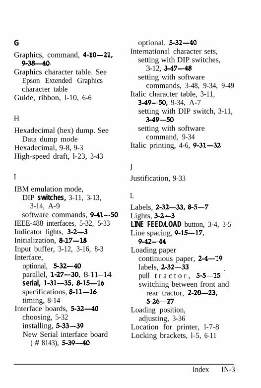
G
Graphics, command, 4-10-21,9-38-40.
Graphics character table. SeeEpson Extended Graphicscharacter table
Guide, ribbon, l-10, 6-6
H
Hexadecimal (hex) dump. SeeData dump mode
Hexadecimal, 9-8, 9-3High-speed draft, l-23, 3-43
I
IBM emulation mode,DIP switches, 3-11, 3-13,
3-14, A-9software commands, 9-41-50
IEEE-488 interfaces, 5-32, 5-33Indicator lights, 3-2-3Initialization, 8-17-18Input buffer, 3-12, 3-16, 8-3Interface,
optional, 5-32--40parallel, l-27-30, 8-11--14serial, 1-31-35, 8-15-16specifications, 8-11-16timing, 8-14
Interface boards, 5-32--40choosing, 5-32installing, 5-33-39New Serial interface board
( # 8143), 5-39-40
optional, 5-32-40International character sets,
setting with DIP switches,3-12, 3-47-48
setting with softwarecommands, 3-48, 9-34, 9-49
Italic character table, 3-11,3-49-50, 9-34, A-7setting with DIP switch, 3-11,
3-49-50setting with software
command, 9-34Italic printing, 4-6, 9-31-32
JJustification, 9-33
L
Labels, 2-32-33, 8-5-7Lights, 3-2-3LINE FEED/LOAD button, 3-4, 3-5Line spacing, 9-15-17,
9-42-44Loading paper
continuous paper, 2-4-19labels, 2-32-33pull t r a c t o r , 5-5-15 ’switching between front and
rear tractor, 2-20-23,5-26-27
Loading position,adjusting, 3-36
Location for printer, l-7-8Locking brackets, l-5, 6-11
Index IN-3
M
Maintaining the printer, 6-2~12Margins, 9-19-20, 9-46Master Select, 4-8-9, 9-24Maximum paper widths, 8-5Mechanical specifications, 8-9MICRO FEED button, 3-4, 3-5Moving the printer, l-2,
6-9-12Multi-part forms, 2-30-31,
3-20-32, 8-8-9overlapping, 2-31, 3-20-23,
8-7with labels, 2-31, 3-24-29,
8-8
N
Near letter quality (NLQ), l-20,l-24, 3-43-44; 4-2-3
Normal draft, l-24, 3-44,
0
ON LINE,button, 3-4light, 3-2-3
Options,
4-2
interface boards, 5-32-40paper cutter, 5-19-31pull tractor, S-2-18
P
Page length, 3-17setting with DIP switch, 3-12,
3-17setting with software
commands, 9-13-14Panel, control, 3-2-5Paper,
loading continuous paper,2-4-19
positioning, 2-2-3specifications, 8-3-9switching between front and
rear tractor, 2-24-23,5-26-27, 9-12
thickness, 8-6Paper bail, 5-5, 5-14Paper cutter, ‘5-19-31
installing, 5-19-22paper handling, 5-23-28removing, 5-28-31
Paper handling,continuous paper, 2-2-28labels, 2~32-33multi-part forms, 2-30-31paper cutter, 5-23-28pull tractor, 5-5-15
Paper memory, 3-20-32PAPER OUT light, 3-2, 3-3PAPER SELECT panel, 3-2, 3-3Paper separator, 5-3, 5-17, 5-18
with pull tractor, 5-3, 5-17,5-18
IN-4 Index
Paper thickness, 8-6Paper weight, 8-6Paper width, 8-5Parallel interface,
connecting, l-27-30DIP switch settings, 3-13pin assignments, a-11-14specifications, a-11-14timing, 8-14
Parity, 3-13, 3-15Parts, printer, see the inside of
the back cover of this ‘manualPica. See Character spacingPin assignments, 8-11-14, 8-16Pitch. See character spacingPlace, choosing, l-7-8Plugging in printer, l-13-14Positioning paper supply,2-2-3
Power cable, l-3, l-13-14POWER light, 3-2Power supply, connecting to,
l-13-14Print direction, 8-2, 9-10Print head,
life, 8-9operation when printing
graphics, 4-11-14protector, l-5, 6-12
Print quality, 4-2-3Printer,
cleaning, 6-2-3options, 5-2-40parts, see the inside of the
back cover of this manualplugging in, l-13-14
selection menu, l-36-37setting up, l-2-37specifications, 8-2-Mstand, l-8testing, l-13-25transporting, 6-9-12troubleshooting, 7-2-23unpacking, l-2-6weight, 8-9
Printer selection menus,l-36-37
Printer stand, l-8Printing position,
adjusting, 3-37-39Printing speed, 8-2Problems and solutions,l-24-25, 7-2-23
P r o p o r t i o n a l ,spacing, 3-45, 4-3-4, 9-25,
9-47width tables, AL2-5
Protective materials, l-4-6,6-11-12
Pull tractor, 5-2-18installing, 5-2-7paper handling, 5-7-15removing, 5-15-18
R
READY light, 3-2Rear tractor, loading paper on,
2-11-19R i b b o n ,
guide, l-10, 6-6installing, l-9-12
Index IN-5
life, 8-9replacing, 6-4-8
Roman, 34344, 4-2, 9-23,9-46
RS-232C-compatible seriali n t e r f a c e , 5-32
S
Sans Serif, 3-43--44, 4-2, 9-23,9-46
Self test,running, 1-15-24solving any problems,
l-24-25Sending commands to the
printer, 9-3-4Serial interface(s),
connecting, 1-31-35DIP switch settings, 3-13pin assignments, 8-16specifications, 8-15-16
Setting up the printer, l-2-37Short tear-off,
adjusting, 3-35-37Size, character, 4-4, 9-25-28,9-46-48
Skip over perforation, 3-18-19setting with DIP switch, 3-3,
3-18’ setting with software
command, 9-14-15Slashed zero, 3-11, 3-14Software. See Application
programSoftware commands, 9-2-50
Solutions, 1-24-25, 7-2-23Special effects and emphasis,4-5-7
Special paper,printing on, 2-29-33
Specifications,interface, g-11-16printer, 8-2-10
Stand, printer, l-8Subscript, 4-7, 9-M-31Superscript, 4-7, 9-30-31Switches, DIP, 3-6-14
T
TEAR OFF,button, 3-4, 3-5light, 3-2, 3-3
Tear-off mode, 3-5, 3-35-37Tear-off position, 3-5, 3-35-37Technical specifications, g-2-18Testing,
self test, 1-15-25using data dump mode,
3-51-53Timing, parallel interface, 8-14TOP OF FORM,
button, 3-4, 3-5light, 3-2, 3-3
Top of form position, 3-29-32Tractor,
arrow lights, 3-2, 3-3front, 2-4-10pull, 5-2-18rear, 2-11-19
IN-6 Index
switching between front andrear, 2-20-23, 5-26-27,9-12
Transporting the printer,6-9-12
Troubleshooting, 7-2-23Twinax interface, 6, 5-32, 5-33Typstyles,
character fonts, 3-43--44,4-2--3, 8-3, 9-46
character spacing, 3-45,4-3-4, 9-25, 9-47
selecting with Master Select,4-G-9, 9-24
special effects and emphasis,4-5-7
W
Weight, printer, 8-9Width detection, 2-2Word processing, 9-33
Z
Zero, slashed, 3-11, 3-14
U
Underlining, 4-7, 9-32Unidirectional printing, 8-2,
9-10Unpacking, l-2-6User-defined characters,
4-22-28, 9-36-37, 9-50
V
Voltage, 8-10power supply, l-13-14
Index IN-7
EPSO
DFX-8000
Quick Reference
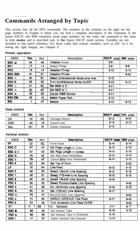
Commands Arranged by TopicThis section lists all the DFX commands. The numbers in the columns on the right are thepage numbers in Chapter 9 where you can find a complete description of the command. If theEpson ESC/P and IBM emulation mode page numbers are the same, the command is the samein both modes and is described only in the Epson ESC/P mode section. Variables are notincluded in this quick reference. For those codes that contain variables, such as ESC Q n forsetting the right margin, see Chapter 9.
Printer operation
ASCII Dee Hex Description ESC/P page IBM page
ESC @ 64 40 Initialize Printer 9-9
DC1 17 11 Select Printer 9-9 9-9
Data control
ASCII Dee Hex Descrlptlon ESC/P pege IBM page
CR 13 OD Carriage Return 9-12 9-12
CAN 24 18 Cancel Line 9-13 9-13
DEL 127 7F Delete Character 9-13
Vertical motion
ASCIIFFESC C
Dee1267
Hex Descrlptlon 1 ESC/P page 1 IBM pageoc Form Feed 1 9.lA 1 !&IA
A3 sat Paoa I arm
- -
-. ‘- Jth in Lines 9-13 9-13
ESC C 0 67 43 & Pa& length in Inches 9-14 9-14
ESC N 70 4E Set Skip Over Perforation 9-14 9-14
ESC 0 79 4F Cancel Skio Over Perforation 9-15 9-15
t ESC3 51 33 1 Set n/216-inch Line F
ESC A 65 41 I Set n/72-inch Line Spacing
IVT 1 11 1 OB 1 Tab Verticallv,I P-17 I 9.17
ESC B 66
ESC b 98ESC I 47
- -42 Set Vertical Tabs 9-18 9-18
62 Set Vertical Tabs in Channels 9-18
2F Select Vertical Tab Channel 9-19
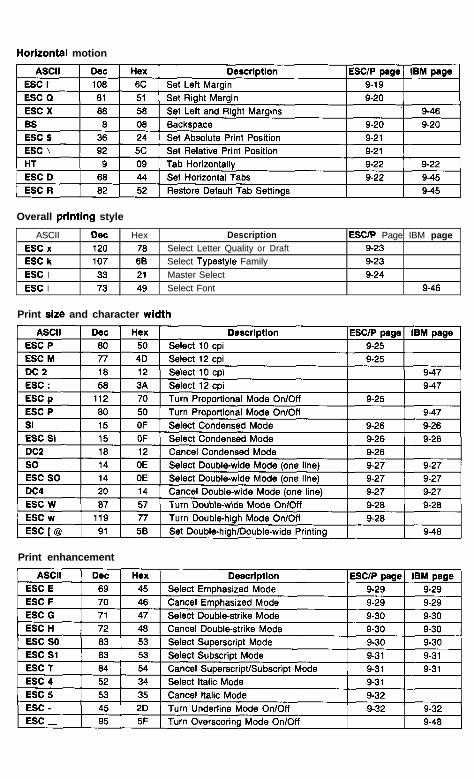
Horizontal motion
Overall printing style
ASCII Dee
ESC x 120ESC k 107
ESC I 33
ESC I 73
Hex Description76 Select Letter Quality or Draft
6E Select Typestyle Family
21 Master Select
49 Select Font
ESClP Page IBM page9-23
9-239-24
9-46
Print size and character width
Print enhancement
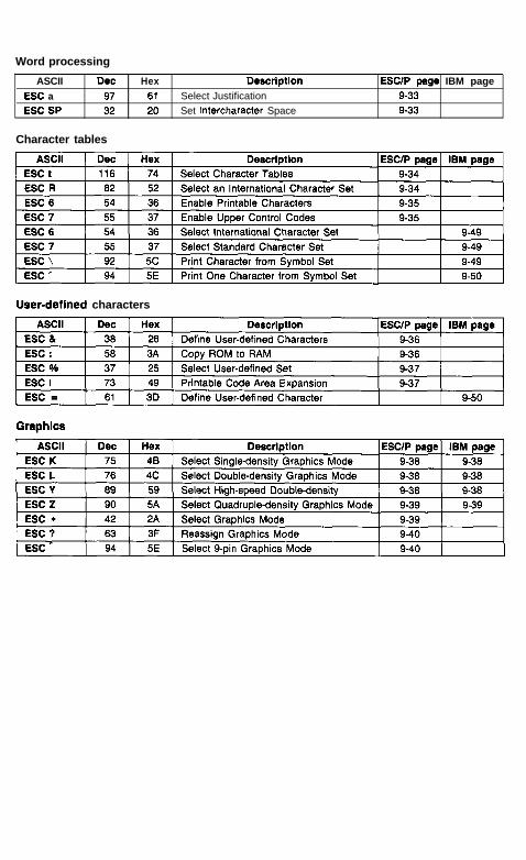
Word processing
ASCII DeeESC a 97ESC SP 32
Hex Descrlptlon61 Select Justification
20 Set Intercharacter Space
ESCtP page IBM page9-33
9-33
Character tables
User-defined characters
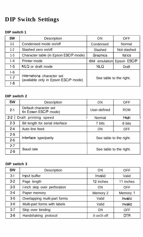
DIP Switch Settings
DIP switch 1
SW Description ON OFF
1-1 Condensed mode on/off Condensed Normal
1-2 Slashed zero on/off Slashed Not slashed
1-3 Character table (in Epson ESClP mode) Graphics Italics
l-4 Printer mode IBM emulation Epson ESClP
I-5 NLCI or draft mode NLQ Draft
l-6
I-7
I-8
International character set(available only in Epson ESClP mode) See table to the right.
DIP switch 2
SW
2-I
Description
Default character setfin Eoson ESClP mode)
ON
User-defined
OFF
ROM
1 2-2 1 Draft printing speed 1 Normal 1 Hiah 1
2-3
2-4
2-5
2-6
Bit length for serial interface 7 bits 8 bits
Auto line feed ON OFF
Interface type/parity See table to the right.
2-7
2-8Baud rate See table to the right.
DIP switch 3
SW Description ON OFF
3-l Input buffer Invalid Valid
3-2 Page length 12 inches 11 inches
3-3 l-inch skip over perforation ON OFF
3-4 Paper memory Memory 2 Memory 1
3-5 Overlapping multi-part forms Valid Invalid
3-6 Multi-part forms with labels Valid Invalid
3-7 Skip over binding ON OFF
3-8 Handshaking protocol X-on/X-off DTR
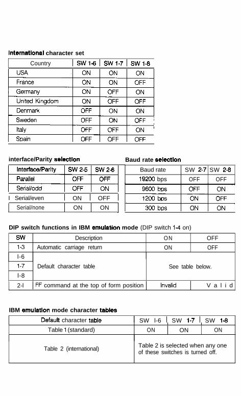
international character set
Country 1 SWl-6 1 SWl-7 1 SWl-6 1
interface/Parity selection
I Serial/even 1 ON 1 OFF 1
Serial/none 1 ON 1 ON 1
Baud rate selection
Baud rate SW 2-7 SW 2-8
19200 bps OFF OFF
DIP switch functions in IBM emulation mode (DIP switch 14 on)
SW Description ON
1-3 Automatic carriage return ON
l-6
OFF
OFF
1-7 Default character table See table below.
l-8
1 2-l 1 FF command at the top of form position 1 Invalid V a l i d
IBM emulation mode character tables
Default character table 1 SW l-6 I SW 1-7 1 SW 1-6
Table 1 (standard)I I
ON 1 ON ON
Table 2 (international) Table 2 is selected when any oneof these switches is turned off.
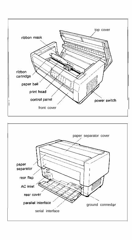
top cover
front cover
paper separator cover
ground conned:or,
serial interface

DFX-8000
u71xIIll0cl0

EPSON AMERICA, INC. 2780 Lomita Boulevard, Torrance, California 90505
EPSON® Pm&d I” Japan 91 .04-l .!


![%D7%AA%D6%B7%D6%BC%D7%A8%D6%B0%D7%A9 · D7%AA%D6%B7%D6%BC%D7%A8%D6%B0%D7%A9 ... • Jonah 1:3 (Jonah 1:3 [5]), ... Aššur Babylon E](https://img.pdfslide.us/doc/110x75/5b0448167f8b9a2d518d665e/d7aad6b7d6bcd7a8d6b0d7a9-d7aad6b7d6bcd7a8d6b0d7a9-.jpg)

![Æ ]& · B È ç ö .¢ 1¥ôó ù n ' Ö × Xôc n ç øq D üô`6Wd æ o Î÷ ô w ¢m æ÷ o } s @ Äö)ú,Ðö ô231* ½c :¹>Á Àb ôÁ D w Îô P wcÌ; Àbö > õ> ôÌ > c](https://img.pdfslide.us/doc/110x75/5ec3d991b045af293a53af70/-b-1-n-xc-n-q-d-6wd-o-.jpg)


![ØµÙ†Ø Ù⁄ شخصÙ− بÙ⁄بًد Ù–Ø Ø¨Ù− - Ù…Ù ... · 2016-09-18 · 0lud]hl * ,qioxhqfh ri +\gurwkhupdo 7uhdwphqw rq %rqg 6khdu 6wuhqjwk lq](https://img.pdfslide.us/doc/110x75/5fb4e462009a4b13793958dc/a-a-a-aa-a-a-.jpg)