Embed Size (px)
Citation preview
Copyright ASME International Provided by IHS under license with ASME
Not for ResaleNo reproduction or networking permitted without license from IHS
--```,,,-`-`,,`,,`,`,,`---

Copyright ASME International Provided by IHS under license with ASME
Not for ResaleNo reproduction or networking permitted without license from IHS
--```,,,-`-`,,`,,`,`,,`---

The American Society of Mechanical Engineers
ì N A M E R I C A N N A T I O N A L S T A N D A R D
FACTORY-M AD E WROUGHT
BUTTWELDING FITTINGS
ASME B16.l-2003 (Revision of ASME BI 8.9.2001)
Copyright ASME International Provided by IHS under license with ASME
Not for ResaleNo reproduction or networking permitted without license from IHS
--```,,,-`-`,,`,,`,`,,`---
Date of Issuance: February 20, 2004
The next edition of this Standard is scheduled for publication in 2009. There will be no addenda issued to this edition.
ASME issues written replies to inquiries concerning interpretations of technical aspects of this Standard. The interpretations will be included with this edition.
ASME is the registered trademark of The American Society of Mechanical Engineers.
This code or standard was developed under procedures accredited as meeting the criteria for American National Standards. The Standards Committee that approved the code or standard was balanced to assure that individuals from competent and concerned interests have had an opportunity to participate. The proposed code or standard was made available for public review and comment that provides an opportunity for additional public input from industry, academia, regulatoiy agencies, and the public-at-large.
ASME does not “approve,” “rate,” or “endorse” any item, construction, proprietary device, or activity. ASME does not take any position with respect to the validity of any patent rights asserted in connection with any
items mentioned in this document, and does not undertake to insure anyone utilizing a standard against liability for infringement of any applicable letters patent, nor assume any such liability. Users o f a code or standard are expressly advised that determination of the validity of any such patent rights, and the risk of infringement of such rights, is entirely their own responsibility.
Participation by federal agency representative($ or person($ affiliated with industry is not to be interpreted as government or industry endorsement of this code or standard.
ASME accepts responsibility for only those interpretations of this document issued in accordance with the established ASME procedures and policies, which precludes the issuance of interpretations by individuals.
No part of this document may be reproduced in any form, in an electronic retrieval system or otherwise,
without the prior written permission of the publisher.
The American Society of Mechanical Engineers Three Park Avenue, New York, NY 10016-5990
Copyright O 2004 by THE AMERICAN SOCIEN OF MECHANICAL ENGINEERS
All Rights Reserved Printed in U.S.A.
Copyright ASME International Provided by IHS under license with ASME
Not for ResaleNo reproduction or networking permitted without license from IHS
--```,,,-`-`,,`,,`,`,,`---
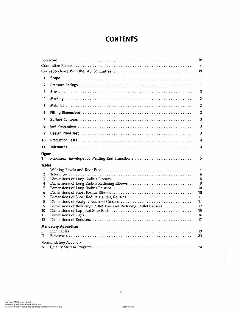
Foreword .............................................................................. Committee Roster ..................................................................... Correspondence With the B16 Committee .............................................. 1 Scope ............................................................................ 2 Pressure Ratings .................................................................. 3 Size .............................................................................. 4 Marking .......................................................................... 5 Material .......................................................................... 6 Fitting Dimensions ................................................................ 7 Surface Contours ............................................................... 8 End Preparation ................................................................... 9 Design Proof lest .................................................................
10 Production Tests ............................................................... 11 Tolerances ..................................................................... Figure 1
Tables
Maximum Envelope for Welding End Transitions ..................................
1 Welding Bevels and Root Face .................................................... 2 Tolerances ........................................................................ 3 Dimensions of Long Radius Elbows ............................................... 4 Dimensions of Long Radius Reducing Elbows ..................................... 5 Dimensions of Long Radius Returns .............................................. 6 Dimensions of Short Radius Elbows ............................. 7 Dimensions of Short Radius 180 deg Returns ...................................... 8 Dimensions of Straight Tees and Crosses .......................................... 9 Dimensions of Reducing Outlet Tees and Reducing Outlet Crosses . . . . . . . . . . . . . . . . .
10 Dimensions of Lap Joint Stub Ends ............................................... 11 Dimensions of Caps .............................................................. 12 Dimensions of Reducers .......................................................... Mandatory Appendices I Inch Tables ....................................................................... II References ........................................................................ Nonmandatory Appendix A Quality System Program ..........................................................
iv V
vi
1
1
2
5
4 6 8 9
10 10 11 11 12 15 16 17
19 33
34
... 111
Copyright ASME International Provided by IHS under license with ASME
Not for ResaleNo reproduction or networking permitted without license from IHS
--```,,,-`-`,,`,,`,`,,`---

ln 1921, the American Engineering Standards Cornittee, later the American Standards Associa- tion (ASA), organized Sectional Committee B16 to unify and further develop national standards for pipe flanges and fittings (and, later, for valves, gaskets, and valve actuators). Cosponsors of the B16 Committee were The American Society of Mechanical Engineers (ACME), the Heating and Piping Contractors National Association [now the Mechanical Contractors Association of America (MCAA)], and the Manufacturers Standardization Society of the Valve and Fittings Industry (MSS). Cosponsors were later designated as cosecretariat organizations.
Standardization of welding fittings was initiated in 1937 by a subgroup (designated Subgroup 6) of Subcommittee 3. After consideration of several drafts, a standard was approved by the Committee, cosponsors, and ASA, and published with the designation ASA B16.9-1940.
Revisions were made in 1950 and 1955 to add sizes up to NPS 24 and to complete coverage of fittings in some sizes. These revisions were approved and published as ASA B16.9-1951 and ASA B16.9-1958. With the subgroup now designated Subcommittee 6 (later Subcommittee F), further revisions were begun to clarify the intent of the standard, to add angularity tolerances, and to include fittings of different types (long radius reducing elbows and crosses) and smaller sizes (NPS '/4 and x). This revision was published as ASA B16.9-1964 after ASA approval.
After reorganization of ASA, first as the United States of America Standards Institute (USASI), then as the American National Standards Institute (ANSI), with the Sectional Committee being redesignated as an American National Standards Committee, another revision increasing the size range to NI'S 48 and revising the text for clarity was approved and published as ANSI B16.9-1971.
In 1975, Subcommittee F began a major revision to bring the standard up to date with current practice and usage. Common fractions were expressed as decimals (but without intending higher precision) and metric dimensional equivalents were added. Provisions for step-wise change of radius for NPS % long radius elbows and 180 deg returns were introduced. Following Standards Committee, cosecretariat, and ANSI approval, the revision was published as ANSI B16.9-1978. It was updated by a corrective addendum, B16.9a-1981, issued in February 1982. Ln 1982, American National Standards Committee B16 was reorganized as an ACME Committee
operating under procedures accredited by ANSI. In ASME/ANSI B16.9-1986, the text was revised and inch dimensions were established as the standard.
In 1991, the Subcommittee reviewed the document and made a number of revisions that were included in ACME 816.9-1993. Dimensions for short pattern lap joints were also added.
In ACME B16.9-2001, short radius elbows and returns were added, which included all dimen- sions and tolerances of ACME B16.28-1994. Metric units were provided as an independent but parallel alternative standard to U.S. customary units and a Quality System Program appendix was added.
In 2003, the Subcommittee reviewed the document and made a number of revisions. The scope of the standard was changed to permit fabricated lap joint stub ends employing circumferential or intersection welds.
This Standard was approved as an American National Standard on October 15, 2003 and December 31, 2003.
iv
Copyright ASME International Provided by IHS under license with ASME
Not for ResaleNo reproduction or networking permitted without license from IHS
--```,,,-`-`,,`,,`,`,,`---
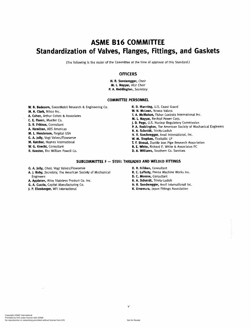
ASME B16 COMMITTEE Standardization of Valves, Flanges, Fittings, and Gaskets
(The following is the roster of the Committee at the time of approval of this Standard.)
OFFICERS H. R. Sonderegger, Chair M. L. Nayyar, Vice Chair
P. A. Reddington. Secretary
COMMITTEE PERSONNEL
W. B. Bedesem, ExxonMobil Research & Engineering Co. M. A. Clark, Nibco Inc. A. Cohen, Arthur Cohen & Associates C. E. Floren, Mueller Co. D. R. Frikken, Consultant A. Hamilton, ABS Americas M. L. Henderson, Forgital USA G. A. Jolly, Vogt Valves/Flowserve M. Katcher, Haynes International W. G. Knecht, Consultant R. Koester. The William Powell Co.
R. D. Manning, U.S. Coast Guard W. N. McLean, Newco Valves T. A. McMahon, Fisher Controls International Inc. M. L. Nayyar, Bechtel Power Corp. J. D. Page, U.S. Nuclear Regulatory Commission P. A. Reddington, The American Society of Mechanical Engineers R. A. Schmidt, Trinity-Ladish H. R. Sonderegger, Anvil International, Inc. W. M. Stephan, Flexitallic LP T. F. Stroud, Ductile Iron Pipe Research Association R. E. White, Richard E. White & Associates PC D. A. Williams, Southern Co. Services
SUBCOMMITTEE F - STEEL THREADED AND WELDED FIllINGS
G. A. Jolly, Chair, Vogt Valves/Flowserve A. J. Roby, Secretary, The American Society of Mechanical
A. Appleton, Alloy Stainless Product Co. Inc. G. A. Cuccio. Capital Manufacturing Co. J. P. Ellenberger, WFI International
D. R. Frikken. Consultant R. C. Lafferty, Penna Machine Works Inc.
Engineers D. C. Monroe, Consultant R. A. Schmidt, Trinity-Ladish H. R. Sonderegger, Anvil International Inc. K. Umemura, Japan Fittings Association
V
Copyright ASME International Provided by IHS under license with ASME
Not for ResaleNo reproduction or networking permitted without license from IHS
--```,,,-`-`,,`,,`,`,,`---

General. ACME Standards are developed and maintained with the intent to represent the consensus of concerned interests. As such, users of this standard may interact with the Committee by requesting interpretations, proposing revisions, and attending Committee meetings. Correspondence should be addressed to:
Secretary, B16 Standards Committee The American Society of Mechanical Engineers Three Park Avenue New York, NY 10016-5990
Proposing Revisions. Revisions are made periodically to the Standard to incorporate changes that appear necessary or desirable, as demonstrated by the experience gained from the application of the Standard. Approved revisions will be published periodically.
The Committee welcomes proposals for revisions to this Standard. Such proposals should be as specific as possible, citing the paragraph number(s), the proposed wording, and a detailed description of the reasons for the proposal, including any pertinent documentation.
Interpretations. Upon request, the B16 Committee will render an interpretation of any requirement of the Standard. Interpretations can only be rendered in response to a written request sent to the Secretary of the B16 Standards Committee.
The request for interpretation should be clear and unambiguous. It is further recom- mended that the inquirer submit his/her request in the following format:
Subject: Cite the applicable paragraph number(s) and the topic of the inquiry. Edition: Cite the applicable edition of the Standard for which the interpretation
is being requested. Question: Phrase the question as a request for an interpretation of a specific
requirement suitable for general understanding and use, not as a request for an approval of a proprietary design or situation. The inquirer may also include any plans or drawings which are necessary to explain the question; however, they should not contain proprietary names or information.
Requests that are not in this format will be rewritten in this format by the Committee prior to being answered, which may inadvertently change the intent of the original request.
ACME procedures provide for reconsideration of any interpretation when or if additional information that might affect an interpretation is available. Further, persons aggrieved by an interpretation may appeal to the cognizant ACME Committee or Subcommittee. ACME does not "approve," "certify," "rate," or "endorse" any item, construction, proprietary device, or activity.
Attending Committee Meetings. The B16 Standards Committee regularly holds meetings, which are open to the public. Persons wishing to attend any meeting should contact the Secretary of the B16 Standards Committee.
vi
Copyright ASME International Provided by IHS under license with ASME
Not for ResaleNo reproduction or networking permitted without license from IHS
--```,,,-`-`,,`,,`,`,,`---
ASME 816.9-2003
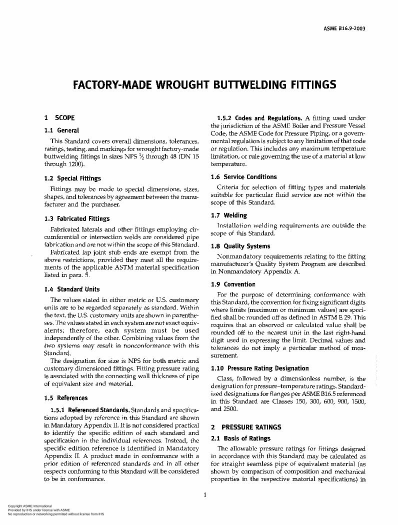
1 SCOPE
1.1 General
This Standard covers overall dimensions, tolerances, ratings, testing, and markings for wrought factory-made buttwelding fittings in sizes NPS */2 through 48 (DN 15 through 1200).
1.2 Special Fittings
Fittings may be made to special dimensions, sizes, shapes, and tolerances by agreement between the manu- facturer and the purchaser.
1.3 Fabricated Fittings
Fabricated laterals and other fittings employing cir- cumferential or intersection welds are considered pipe fabrication and are not within the scope of this Standard.
Fabricated lap joint stub ends are exempt from the above restrictions, provided they meet all the require- ments of the applicable ASTM material specification listed in para. 5.
1.4 Standard Units
The values stated in either metric or U.S. customary units are to be regarded separately as standard. Within the text, the U.S. customary units are shown in parenthe- ses. The values stated in each system are not exact equiv- alents; therefore, each system must be used independently of the other. Combining values from the two systems may result in nonconformance with this St andard.
The designation for size is NPS for both metric and customary dimensioned fittings. Fitting pressure rating is associated with the connecting wall thickness of pipe of equivalent size and material.
1.5 References
1.5.1 Referenced Standards. Standards and specifica- tions adopted by reference in this Standard are shown in Mandatory Appendix II. It is not considered practical to identify the specific edition of each standard and specification in the individual references. Instead, the specific edition reference is identified in Mandatory Appendix II. A product made in conformance with a prior edition of referenced standards and in all other respects conforming to this Standard will be considered to be in conformance.
FACTORY-MADE WROUGHT BUllWELDI NG FITTINGS
1
1.5.2 Codes and Regulations. A fitting used under the jurisdiction of the ACME Boiler and Pressure Vessel Code, the ACME Code for Pressure Piping, or a govern- mental regulation is subject to any limitation of that code or regulation. This includes any maximum temperature limitation, or rule governing the use of a material at low temperature.
1.6 Service Conditions Criteria for selection of fitting types and materials
suitable for particular fluid service are not within the scope of this Standard.
1.7 Welding Installation welding requirements are outside the
scope of this Standard.
1.8 Quality Systems Nonmandatory requirements relating to the fitting
manufacturer’s Quality System Program are described in Nonmandatory Appendix A.
1.9 Convention For the purpose of determining conformance with
this Standard, the convention for fixing significant digits where limits (maximum or minimum values) are speci- fied shall be rounded off as defined in ASTM E 29. This requires that an observed or calculated value shall be rounded off to the nearest unit in the last right-hand digit used in expressing the limit. Decimal values and tolerances do not imply a particular method of mea- surement.
1.10 Pressure Rating Designation Class, followed by a dimensionless number, is the
designation for pressure-temperature ratings. Standard- ized designations for flanges per ACME B16.5 referenced in this Standard are Classes 150, 300, 600, 900, 1500, and 2500.
2 PRESSURE RATINGS
2.1 Basis of Ratings The allowable pressure ratings for fittings designed
in accordance with this Standard may be calculated as for straight seamless pipe of equivalent material (as shown by comparison of composition and mechanical properties in the respective material specifications) in
Copyright ASME International Provided by IHS under license with ASME
Not for ResaleNo reproduction or networking permitted without license from IHS
--```,,,-`-`,,`,,`,`,,`---

ASME 816.9-2003 FACTORY-MADE WROUGHT BUTMIELDING FITTINGS
accordance with the rules established in the applicable sections of ACME B31, Code for Pressure Piping. For the calculation, applicable data for the pipe size, wall thickness, and material that is equivalent to that of the fitting shall be used. Pipe size, wall thickness (or sched- ule number), and material identity on the fittings are in lieu of pressure rating markings.
2.2 Design of Fittings The design of fittings shall be established by mathe-
matical analyses (e.g., ACME B16.49 for bends) contained in nationally recognized pressure vessel or piping codes, or at the manufacturer?s option by proof testing in accor- dance with para. 9 of this Standard. In order to meet design or manufacturing requirements, it is expected that some portion of formed fittings may have to be thicker than the pipe wall with which the fitting is intended to be used. The mathematical analyses, if used, may take into account such thicker sections. Records of mathematical analysis and/or successful proof test data shall be available at the manufacturer?s facility for inspection by the purchaser.
3 SIZE
NPS, followed by a dimensionless number, is the des- ignation for nominal fitting size. NPS is related to the reference nominal diameter, DN, used in international standards. The relationship is, typically, as follows:
DN NPS
15 20 25 32
40 50 65 80
100
% %
1% 1
1?4
2% 2
3 4
NOTE: For NPS > 4, the equivalence is DN = 25(NPS).
4 MARKING
4.1 Standard Marking Each fitting shall be permanently marked to show the
(u) manufacturer?s name or trademark íb) material identification, either the ASTM or ACME
(c) schedule number? or nominal wall thickness in
following:
grade designation
mm
Schedule number is a dimensionless number that is widely used as a convenient designation for use in ordering pipe and fittings. It is normally associated with a group of standardized pipe wall thickness. Refer to ASME B36.10M and ASME B36.19M for com- plete details on pipe schedule numbers.
(d) size - the nominal pipe size (NPS) identification number related to the end connections shall be used
(e) compliance - see para 4.4 for standard and special fitting marking
A manufacturer may supplement these mandatory markings with others, including a DN size designation, but confusion with the required marking shall be avoided.
4.2 Exceptions Where the size of the fitting does not permit complete
marking, the identification marks may be omitted in reverse of the order presented above.
4.3 Depth of Stamping Where steel stamps are used, care shall be taken so
that the marking is not deep enough or sharp enough to cause cracks or to reduce the wall thickness of the fitting below the minimum allowed.
4.4 Compliance
4.4.1 Standard Fittings. That the fitting was manufac- tured in conformance with this Standard, including all dimensional requirements, is certified by a prefix ?WP? in the material grade designation marking.
4.4.2 Special Fittings. That the fitting was manufac- tured in conformance with this Standard, except that dimensional requirements are as agreed between the purchaser and the manufacturer, is certified by a supple- mentary suffix to the material grade designation mark- ing as follows:
(a) ?S9? applies for fittings in accordance with ASTM A 234, A 403, A 420, and A 815.
(b) ?SPLD? applies for fittings in accordance with ASTM B 361, B 363, and B 366.
5 MATERIAL
Wrought fittings covered by this Standard shall be in accordance with ASTM A 234, A 403, A 420, A 815, B 361, B 363, B 366, or the corresponding standard listed in Section II of the ASME Boiler and Pressure Vessel Code. The term wrought denotes fittings made of pipe, tubing, plate, or forgings. Fittings made from block forg- ings may only be supplied subject to agreement between the manufacturer and purchaser. Such fittings need not meet the requirements of para. 7.
6 FITTING DIMENSIONS
6.1 General
This Standard provides for a fixed position for the welding ends with reference to either the centerline of the fittings or the overall dimensions. Dimensional requirements for these fittings are to be found in Tables
2 Copyright ASME International Provided by IHS under license with ASME
Not for ResaleNo reproduction or networking permitted without license from IHS
--```,,,-`-`,,`,,`,`,,`---

FACTORY-MADE WROUGHT BUTWELDING FITTINGS ASME 816.9-2003
3 through 12 and Tables I2 through I11 of Mandatory Appendix I.
6.2 Special Dimensions
6.2.1 Fatigue loading. For applications where fatigue loading is a concern, required minimum dimensions shall be furnished by the purchaser.
6.2.2 Bore Diameter. Bore diameters away from the ends are not specified. If special flow path requirements are needed, the bore dimensions shall be specified by the purchaser.
6.2.3 Stub Ends. Service conditions and joint con- struction often dictate stub end length requirements. Therefore, the purchaser must specify long or short pat- tern fitting when ordering. [See General Note (c) in Tables 10 and 19.1
7 SURFACE CONTOURS
Where adjacent openings in fittings are not in parallel planes, they shall be joined by a circular arc or radius on the external surfaces. The arc or radius may be termi- nated in tangents. Except as provided for block forgings (see para. 5), the projected profile of external surfaces of fittings shall not have sharp intersections (corners) and/or collapsed arcs.
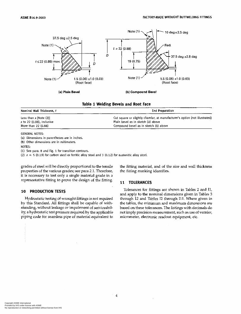
8 END PREPARATION
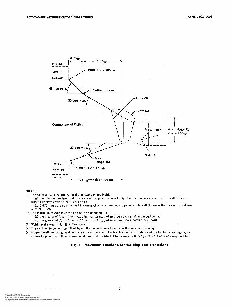
Unless otherwise specified, the details of the welding end preparation shall be in accordance with Table 1. Transitions from the welding bevel to the outside surface of the fitting and from the root face to the inside surface of the fitting lying within the maximum envelope shown in Fig. 1 are at the manufacturer's option, except as covered in Note (5) of Fig. 1 or unless otherwise specifi- cally ordered.
9 DESIGN PROOF TEST
9.1 Required Tests Proof tests shall be made as set forth in this Standard
when the manufacturer chooses proof testing to qualify the fitting design. Unless otherwise agreed upon between the manufacturer and purchaser, the proof test shall be one based on the computed bursting pressure of the fitting and its connecting piping.
Lap joint stub ends are exempt from proof testing because they are used in a flange assembly, which will have different ratings depending on service application.
9.2 Test Assembly
9.2.1 Representative Components. Fittings that are representative of production and selected for test shall be identified as to material, grade, and lot, including
heat treatment. They shall be inspected for dimensional compliance to this Standard.
9.2.2 Other Components. Straight seamless or welded pipe sections whose calculated bursting strength is at least as great as the proof test pressure as calculated in para. 9.3 shall be welded to each end of the fitting to be tested. Any internal misalignment greater than 1.5 mm (0.06 in.) shall be reduced by taper boring at a slope not over 1:3. Length of pipe sections for closures shall be as follows:
(u) Minimum length of pipe shall be one pipe O.D. for NI'S 14 (DN 350) and smaller.
(b) Minimum length of pipe shall be one-half pipe O.D. for NI'S greater than 14 (DN 350).
9.3 Test Procedure Test fluid shall be water or other liquid used for hydro-
static testing. Hydrostatic pressure shall be applied to the assembly. The test is successful if the assembly with- stands, without rupture, 105% of the computed proof test pressure defined below.
2st p = - D
where D = specified outside diameter of pipe P = computed minimum proof test pressure for
fitting S = actual tensile strength of the test fitting, deter-
mined on a specimen representative of the test fitting, which shall meet the tensile strength requirements of the applicable material of para. 5
t = nominal pipe wall thickness of the pipe that the fitting marking identifies
NOTE: Any dimensionally consistent system of units may be used.
9.4 Applicability of Test Results It is not necessary to conduct an individual test of
fittings with all combinations of sizes, wall thicknesses, and materials. A successful proof test on one representa- tive fitting may represent others to the extent described in paras. 9.4.1, 9.4.2, and 9.4.3.
9.4.1 Size Range. One test fitting may be used to qualify similarly proportioned fittings with a size range from one-half to twice that for the tested fitting. The test of a nonreducing fitting qualifies reducing fittings of the same pattern. The test of a reducing fitting qualifies reductions to smaller sizes.
9.4.2 Thickness Range. One test fitting may be used to qualify similarly proportioned fittings with t / D ranges from one-half to three times that for the tested fitting.
9.4.3 Material Grades. The pressure retaining capac- ity of a geometrically identical fitting made of various
3
Copyright ASME International Provided by IHS under license with ASME
Not for ResaleNo reproduction or networking permitted without license from IHS
--```,,,-`-`,,`,,`,`,,`---
ASME 816.9-2003
Note (1
FACTORY-MADE WROUGHT BUTIWELDING FIllINGS
37.5 deg 12.5 deg
(a) Plain Bevel
t
Note (1) ’ 1.5 (0.06) il .O (0.03) (Root face)
-
>
- t
22 (0.88)
c .5
Note (1) 1.5 (0.06) il .O (0.03) (Root face)
(b) Compound Bevel
Table 1 Welding Bevels and Root Face
Nominal Wall Thickness, t
Less than x [Note (2)] x to 22 (0.88), inclusive More than 22 (0.88)
End Preparation
Cut square or slightly chamfer, at manufacturer’s option (not illustrated) Plain bevel as in sketch (a) above Compound bevel as in sketch (b) above
GENERAL NOTES: (a) Dimensions in parentheses are in inches. (b) Other dimensions are in millimeters. NOTES: (1) See para. 8 and Fig. 1 for transition contours. (2) x = 5 (0.19) for carbon steel or ferritic alloy steel and 3 (0.12) for austenitic alloy steel.
grades of steel will be directly proportional to the tensile properties of the various grades; see para 2.1. Therefore, it is necessary to test only a single material grade in a representative fitting to prove the design of the fitting.
10 PRODUCTION TESTS
Hydrostatic testing of wrought fittings is not required by this Standard. All fittings shall be capable of with- standing, without leakage or impairment of serviceabil- ity, a hydrostatic test pressure required by the applicable piping code for seamless pipe of material equivalent to
the fitting material, and of the size and wall thickness the fitting marking identifies.
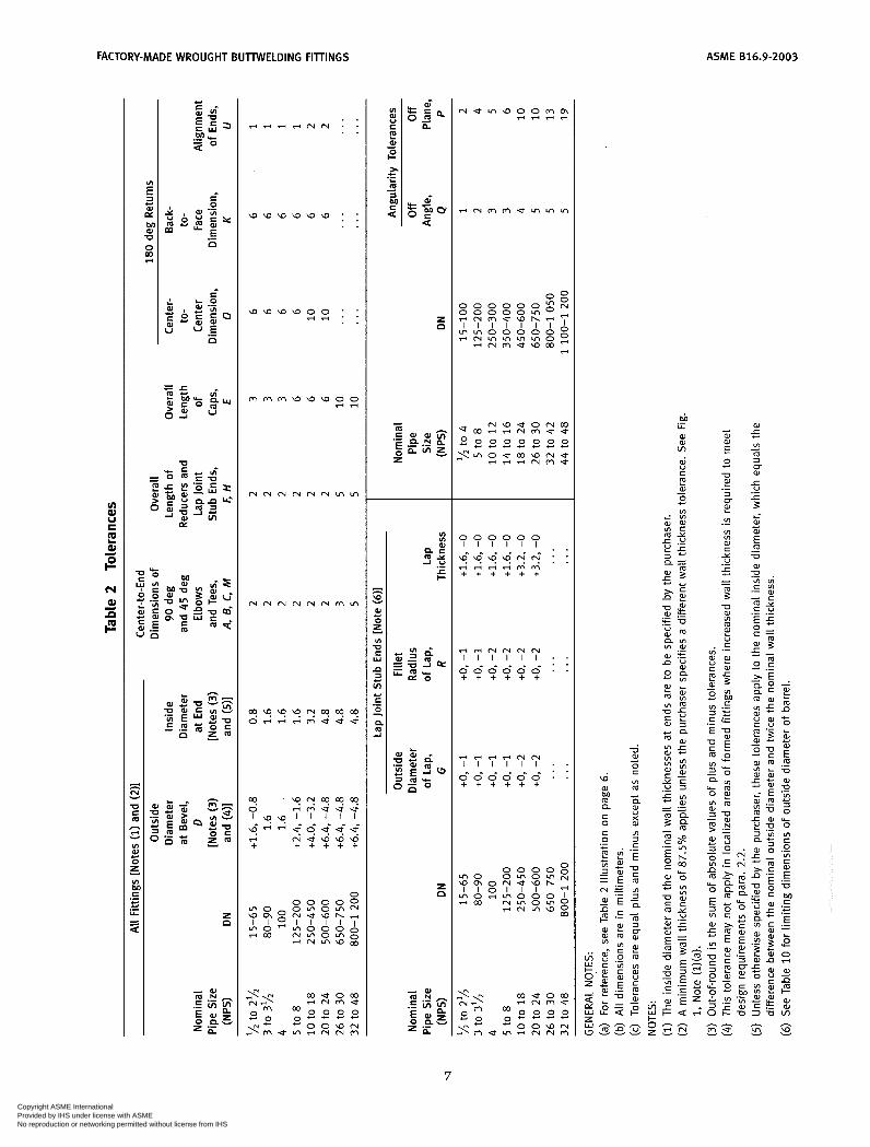
11 TOLERANCES
Tolerances for fittings are shown in Tables 2 and Il, and apply to the nominal dimensions given in Tables 3 through 12 and Tables I2 through I l l . Where given in the tables, the minimum and maximum dimensions are based on these tolerances. The listings with decimals do not imply precision measurement, such as use of vernier, micrometer, electronic readout equipment, etc.
4
Copyright ASME International Provided by IHS under license with ASME
Not for ResaleNo reproduction or networking permitted without license from IHS
--```,,,-`-`,,`,,`,`,,`---
FACTORY-MADE WROUGHT BUTTWELDING FITTINGS
Outside ----c
ASME 616.9-2003
- - - - 1.5tmin A
Component of Fitting
Max. slope 1:3 Inside I\
I Radius 2 0.05rmin Note (5) I
L 2tmin transition region - Inside
Note (3)
/ '-f---r--r---
I tnom h i n Max. [Note (2) l
No& ( I )
NOTES: (1) The value of tmin is whichever of the following is applicable:
(a) the minimum ordered wall thickness of the pipe, to include pipe that is purchased to a nominal wall thickness
(b) 0.875 times the nominal wall thickness of pipe ordered to a pipe schedule wall thickness that has an undertoler- with an undertolerance other than 12.5%;
ance of 12.5%. (2) The maximum thickness at the end of the component is:
(a) the greater of [tmin + 4 mm (0.16 in.)] or 1.15tmin when ordered on a minimum wall basis; (b) the greater of It,,,,, + 4 mm (0.16 in.)] or l.lOtmin when ordered on a nominal wall basis.
(3) Weld bevel shown is for illustration only. (4) The weld reinforcement permitted by applicable code may lie outside the maximum envelope. (5) Where transitions using maximum slope do not intersect the inside or outside surfaces within the transition region, as
shown by phantom outline, maximum slopes shall be used. Alternatively, radii lying within the envelope may be used.
Fig. 1 Maximum Envelope for Welding End Transitions
5
Copyright ASME International Provided by IHS under license with ASME
Not for ResaleNo reproduction or networking permitted without license from IHS
--```,,,-`-`,,`,,`,`,,`---
ASME 816.9-2003 FACTORY-MADE WROUGHT BUTTWELDING FIllINGS
U C a ln .- if
6
Copyright ASME International Provided by IHS under license with ASME
Not for ResaleNo reproduction or networking permitted without license from IHS
--```,,,-`-`,,`,,`,`,,`---
FACTORY-MADE WROUGHT BUTWELDING FITTINGS ASME 616.9-2003
. . r i e 3 . ? l . I " . . . .
w w w w w w : . .
m m m w a w o o riri
N N N N N N ~ ~
c? +-?z?z . s ' " " j ö j j j I w w l I I I I
ri N U W W W + + + + + +
O
r i m m e w h r i i ; '
r i ~ m e w c o ~
I I I I I I I r i m m m m m o u i m o o o o o g
4
0 0 0 0 0 0 1 1 1 1 1 1 ~ ~
w: w w w m N : : r i r i r i r i m m + + + + + +
M .- U W
Ln
2 e W O - Y
7
Copyright ASME International Provided by IHS under license with ASME
Not for ResaleNo reproduction or networking permitted without license from IHS
--```,,,-`-`,,`,,`,`,,`---
ASME 816.9-2003 FACTORY-MADE WROUGHT BUTTWELDING FITTINGS
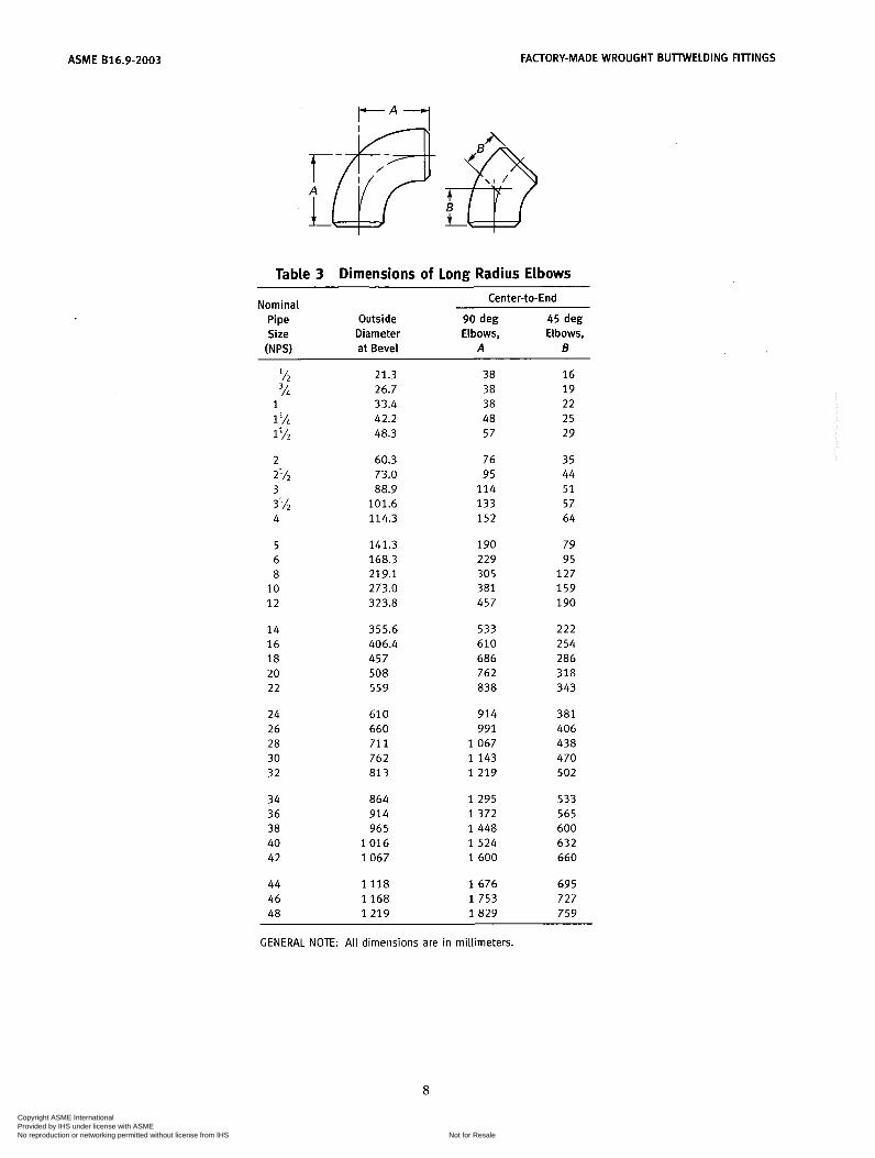
Table 3 Dimensions of Long Radius Elbows Center-to-End Nominal
Pipe Outside 90 deg 45 deg Size Diameter Elbows, Elbows,
INPS) at Bevel A 6
Ih 3/i
1 lh
2%
3Ih
1 1
2
3
4
5 6 8
10 1 2
14 16 18 20 22
24 26 28 30 32
34 36 38 40 42
44 46 48
21.3 26.7 33.4 42.2 48.3
60.3 73.0 88.9
101.6 114.3
141.3 168.3 219.1 273.0 323.8
355.6 406.4 457 508 559
610 660 71 1 762 81 3
864 914 965
1 0 1 6 1067
1 1 1 8 1 1 6 8 1 2 1 9
38 38 38 48 57
76 95
114 133 152
190 229 305 381 457
533 610 686 762 838
914 991
1 0 6 7 1 1 4 3 1 2 1 9
1 2 9 5 1 3 7 2 1 4 4 8 1 5 2 4 1 6 0 0
1 6 7 6 1 7 5 3 1 8 2 9
16 19 22 25 29
35 44 51 57 64
79 95
127 159 190
222 254 286 318 343
381 406 438 470 502
533 565 600 632 660
695 727 759
GENERAL NOTE: All dimensions are in millimeters.
8
Copyright ASME International Provided by IHS under license with ASME
Not for ResaleNo reproduction or networking permitted without license from IHS
--```,,,-`-`,,`,,`,`,,`---
FACTORY-MADE WROUGHT BUTTWELDING FIllINGS ASME 816.9-2003
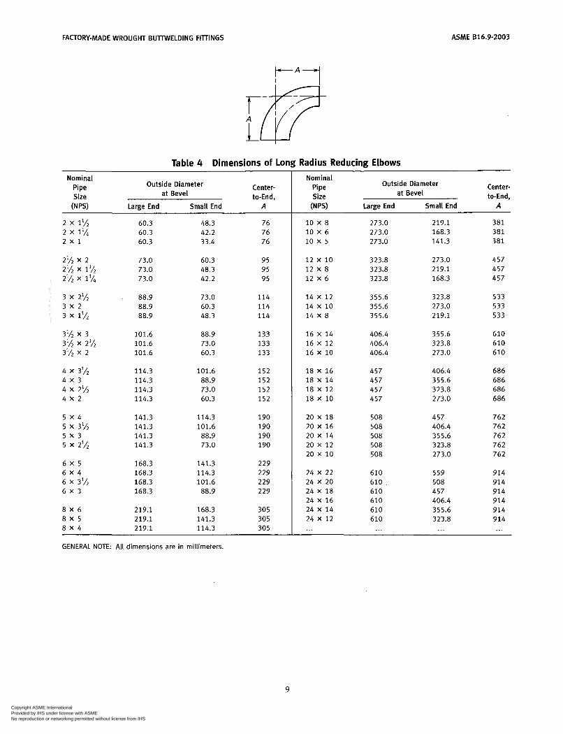
Table 4 Dimensions of Long Radius Reducing Elbows
Nominal Pipe Size
Center- to-End,
Outside Diameter at Bevel
W") Large End Small End A
2 x 1% 60.3 48.3 76 2 x 1% 60.3 42.2 76 2 x 1 60.3 33.4 76
2% x 2 73.0 60.3 95 2% x 1% 73.0 48.3 95 2% x 1% 73.0 42.2 95
3 x 2% 88.9 73.0 114 3 x 2 88.9 60.3 114 3 x 1% 88.9 48.3 114
3% x 3 101.6 88.9 133 3% x 2% 101.6 73.0 133 3lA x 2 101.6 60.3 133
4 x 3lL 114.3 101.6 152 4 x 3 114.3 88.9 152 4 x 2% 114.3 73.0 152 4 x 2 114.3 60.3 152
5 x 4 141.3 114.3 190 5 X 3'/2 141.3 101.6 190 5 x 3 141.3 88.9 190 5 x 2% 141.3 73.0 190
6 x 5 168.3 141.3 229 6 x 4 168.3 114.3 229 6 X 3'L 168.3 101.6 229 6 x 3 168.3 88.9 229
8 x 6 219.1 168.3 305 8 x 5 219.1 141.3 305 8 x 4 219.1 114.3 305
Nominal Pipe Size
Center- to-End,
Outside Diameter at Bevel
W") Large End Small End A
10 X 8 10 X 6 10 x 5
12 x 10 12 X 8 12 x 6
14 X 12 14 X 10 14 X 8
16 X 14 16 X 12 16 X 10
18 X 16 18 X 14 18 X 12 18 X 10
20 X 18 20 X 16 20 X 14 20 x 12 20 x 10
24 X 22 24 X 20 24 X 18 24 X 16 24 X 14 24 X 12 ...
273.0 273.0 273.0
323.8 323.8 323.8
355.6 355.6 355.6
406.4 406.4 406.4
457 457 457 457
508 508 508 508 508
610 610 610 610 610 610
...
219.1 168.3 141.3
273.0 219.1 168.3
323.8 273.0 219.1
355.6 323.8 273.0
406.4 355.6 323.8 273.0
457 406.4 355.6 323.8 273.0
559 508 457 406.4 355.6 323.8
...
381 381 381
457 457 457
533 533 533
610 610 610
686 686 686 686
762 762 762 762 762
914 914 914 914 914 914 ...
GENERAL NOTE: All dimensions are in millimeters.
9
Copyright ASME International Provided by IHS under license with ASME
Not for ResaleNo reproduction or networking permitted without license from IHS
--```,,,-`-`,,`,,`,`,,`---
ASME 816.9-2003 FACTORY-MADE WROUGHT BUTTWELDING FITTINGS
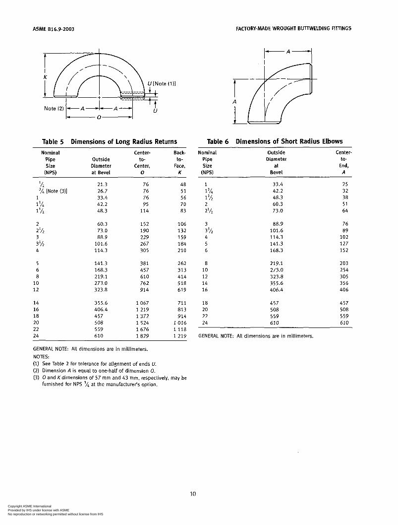
Table 5 Dimensions of long Radius Returns Table 6 Dimensions of Short Radius Elbows
Nominal Center- Back- Pipe Outside to- to- Size Diameter Center, Face,
(N PSI at Bevel O K
Nominal Pipe Size
(NPSI
Outside Diameter
at Bevel
Center- to-
End, A
l/* 21.3 76 48 'A [Note (311 26.7 76 51
1 33.4 76 56 1 'A 42.2 95 70 1% 48.3 114 83
2
3 2%
3 % 4
5 6 8
10 12
60.3 152 106 73.0 190 132 88.9 229 159
101.6 267 184 114.3 305 210
141.3 381 262 168.3 457 3 1 3 219.1 610 414 273.0 762 518 323.8 914 619
14 355.6 1 0 6 7 711 16 406.4 1 2 1 9 813 18 457 1 3 7 2 914 20 5 08 1 5 2 4 1 0 1 6 22 559 1 6 7 6 1 1 1 8 24 610 1 8 2 9 1 2 1 9
GENERAL NOTE: All dimensions are in millimeters. NOTES: (1) See Table 2 for tolerance for alignment of ends U. (2) Dimension A is equal to one-half of dimension O. (3) O and Kdimensions of 57 mm and 43 mm, respectively, may be
furnished for NPS 'A at the manufacturer's option.
1 1% 1%
2 l/2
2
3
4 5 6
3 l/2
8 10 1 2 14 16
18 20 22 24
33.4 42.2 48.3 60.3 73.0
88.9 101.6 114.3 141.3 168.3
219.1 273.0 323.8 355.6 406.4
457 508 559 610
2 5 32 38 5 1 64
76 89
102 127 152
203 254 305 356 406
457 508 559 610
GENERAL NOTE: Al l dimensions are in millimeters.
10
Copyright ASME International Provided by IHS under license with ASME
Not for ResaleNo reproduction or networking permitted without license from IHS
--```,,,-`-`,,`,,`,`,,`---
FACTORY-MADE WROUGHT BUTTWELDING FIlTINGS ASME 816.9-2003
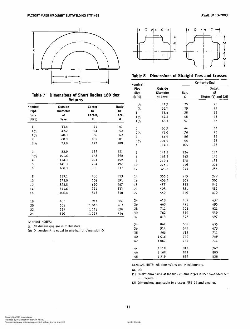
Table 7 Dimensions of Short Radius 180 deg Ret urns
Nominal Outside Center- Back-
Size at Center, Face, Pipe Diameter to- to-
W") Bevel O K
1 1 lh 1 lh
2%
3'h
2
3
4 5 6
8 10 12 14 16
18 20 22 24
33.4 42.2 48.3 60.3 73.0
88.9 101.6 114.3 141.3 168.3
219.1 273.0 323.8 355.6 406.4
457 508 559 610
51 64 76
102 127
152 178 203 254 305
406 508 610 71 1 813
914 1 0 1 6 1 1 1 8 1 2 1 9
41 52 62 81
100
121 140 159 197 237
313 391 467 533 610
686 762 838 914
GENERAL NOTES: (a) All dimensions are in millimeters. [b) Dimension A is equal to one-halF of dimension O.
Table 8 Dimensions of Straight Tees and Crosses Center-to-End Nominal
Pipe Outside Outlet, Size Diameter Run, M
(N PSI at Bevel C [Notes (1) and (2)]
% 3h
1% 1 Y2
2%
3 l h
1
2
3
4
5 6 8 10 12
14 16 18 20 22
24 26 28 30 32
34 36 38 40 42
44 46 48
21.3 26.7 33.4 42.2 48.3
60.3 73.0 88.9
101.6 114.3
141.3 168.3 219.1 273.0 323.8
355.6 406.4 457 508 559
610 660 711 762 813
864 914 965
1 0 1 6 1067
1 1 1 8 1 1 6 8 1 2 1 9
25 29 38 48 57
64 76 86 95
105
124 143 178 216 254
279 305 343 381 419
432 495 5 2 1 559 597
63 5 673 711 749 762
813 851 889
25 29 38 48 57
64 76 86 95
105
124 143 178 216 254
279 305 343 381 419
432 495 5 2 1 559 597
63 5 673 711 749 71 1
762 800 838
GENERAL NOTE: All dimensions are in millimeters. NOTES: (1) Outlet dimension M for NPS 26 and larger is recommended but
not required. (2) Dimensions applicable to crosses NPS 24 and smaller.
11
Copyright ASME International Provided by IHS under license with ASME
Not for ResaleNo reproduction or networking permitted without license from IHS
--```,,,-`-`,,`,,`,`,,`---
ASME 816.9-2003 FACTORY-MADE WROUGHT BUTWELDING FITTINGS
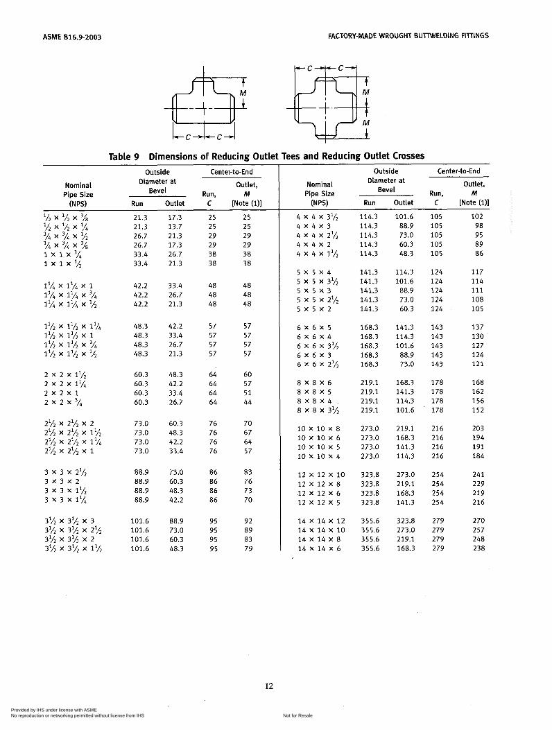
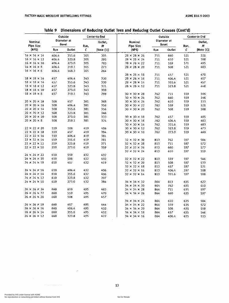
Table 9 Dimensions of Reducing Outlet Tees and Reducing Outlet Crosses Outside Center-to-End
Run, M Outlet, Diameter at
Bevel Nominal
Pipe Size (N PSI Run Outlet C [Note ( l) ]
2 x 2 x 1% 2 x 2 x 1%
2 x 2 x 3/4 2 x 2 x 1
3 x 3 x 2%
3 x 3 x 1% 3 x 3 x 11%
3 X 3 X 2
21.3 21.3 26.7 26.7 33.4 33.4
42.2 42.2 42.2
48.3 48.3 48.3 48.3
60.3 60.3 60.3 60.3
73.0 73.0 73.0 73.0
88.9 88.9 88.9 88.9
101.6 101.6 101.6 101.6
17.3 13.7 21.3 17.3 26.7 21.3
33.4 26.7 21.3
42.2 33.4 26.7 21.3
48.3 42.2 33.4 26.7
60.3 48.3 42.2 33.4
73.0 60.3 48.3 42.2
88.9 73.0 60.3 48.3
25 25 29 29 38 38
48 48 48
57 57 57 57
64 64 64 64
76 76 76 76
86 86 86 86
95 95 95 95
25 25 29 29 38 38
48 48 48
57 57 57 57
60 57 51 44
70 67 64 57
83 76 73 70
92 89 83 79
Outside Center-to-End
Outlet, Diameter at Bevel
Nominal Pipe Size Run, M
(N PSI Run Outlet C [Note (i)]
4 x 4 x 3'/2 4 X 4 X 3
4 X 4 X 2 4 x 4 x 2%
4 x 4 x 1%
5 x 5 x 31h
5 x 5 x 2%
5 X 5 X 4
5 x 5 x 3
5 X 5 X 2
6 X 6 X 5 6 X 6 X 4 6 X 6 X 3% 6 X 6 X 3 6 X 6 X 2%
8 X 8 X 6 8 X 8 X 5 8 X 8 X 4 8 X 8 X 3'h
10 X 10 X 8 10 X 10 X 6 10 x 10 x 5 10 x 10 x 4
12 x 12 x 10 12 X 12 X 8 12 X 12 X 6 12 x 12 x 5
14 X 14 X 12 14 X 14 X 10 14 X 14 X 8 14 X 14 X 6
114.3 114.3 114.3 114.3 114.3
141.3 141.3 141.3 141.3 141.3
168.3 168.3 168.3 168.3 168.3
219.1 219.1 219.1 219.1
273.0 273.0 273.0 273.0
323.8 323.8 323.8 323.8
355.6 355.6 355.6 355.6
101.6 88.9 73.0 60.3 48.3
114.3 101.6
88.9 73.0 60.3
141.3 114.3 101.6
88.9 73.0
168.3 141.3 114.3 101.6
219.1 168.3 141.3 114.3
273.0 219.1 168.3 141.3
323.8 273.0 219.1 168.3
105 105 105 105 105
124 124 124 124 124
143 143 143 143 143
178 178 178 178
216 216 216 216
254 254 254 254
279 279 279 279
102 98 95 89 86
117 114 111 108 105
137 130 127 124 121
168 162 156 152
203 194 191 184
241 229 219 216
270 257 248 238
12
Copyright ASME International Provided by IHS under license with ASME
Not for ResaleNo reproduction or networking permitted without license from IHS
--```,,,-`-`,,`,,`,`,,`---
FACTORY-MADE WROUGHT BUTWELDING FITTINGS ASME 816.9-2003
Table 9 Dimensions of Reducing Outlet Tees and Reducing Outlet Crosses (Cont'd) -
Outside Center-to-End
Outlet, Diameter at Bevel
Nominal Pipe Size Run, M
16 X 16 X 14 16 x 16 x 12 16 x 16 x 10
16 x 16 x 6 16 X 16 X 8
18 X 18 X 16 18 X 18 X 14 18 X 18 X 12 18 X 18 X 10 18 X 18 X 8
20 X 20 X 18 20 X 20 X 16 20 X 20 X 14 20 x 20 x 12 20 x 20 x 10 20 X 20 X 8
22 x 22 x 20 22 X 22 X 18 22 X 22 X 16 22 X 22 X 14 22 x 22 x 1 2 22 x 22 x 10
24 X 24 X 22 24 X 24 X 20 24 X 24 X 18
24 X 24 X 16 24 X 24 X 14 24 X 24 X 1 2 24 X 24 X 10
26 X 26 X 24 26 X 26 X 22 26 X 26 X 20
26 X 26 X 18 26 X 26 X 16 26 X 26 X 14 26 X 26 X 12
406.4 406.4 406.4 406.4 406.4
457 457 457 457 457
508 508 508 508 508 508
559 559 559 559 559 559
610 610 610
610 610 610 610
660 660 660
660 660 660 660
355.6 323.8 273.0 219.1 168.3
406.4 355.6 323.8 273.0 219.1
457 406.4 355.6 323.8 273.0 219.1
508 457 406.4 355.6 323.8 273.0
559 508 457
406.4 355.6 323.8 273.0
610 559 508
457 406.4 355.6 323.8
305 305 305 305 305
343 343 343 343 343
381 381 381 381 381 381
419 419 419 419 419 419
432 432 432
432 432 432 432
495 495 495
495 495 495 495
305 295 283 273 264
330 330 321 308 298
368 356 356 346 333 324
406 394 381 381 371 359
432 432 419
406 406 397 384
483 470 457
444 432 432 422
Center-to-End Outside
Outlet, Diameter at Bevel
Nominal Pipe Size Run, M W") Run Outlet C [Note (l)]
28 X 28 X 26 28 X 28 X 24 28 X 28 X 22 28 X 28 X 20
28 X 28 X 18 28 X 28 X 16 28 X 28 X 14 28 X 28 X 1 2
30 X 30 X 28 30 X 30 X 26 30 X 30 X 24 30 X 30 X 22 30 X 30 X 20
30 X 30 X 18 30 X 30 X 16 30 X 30 X 14 30 X 30 X 1 2 30 X 30 X 10
32 X 32 X 30 32 X 32 X 28 32 X 32 X 26 32 X 32 X 24
32 X 32 X 2 2 32 X 32 X 20 32 X 32 X 18 32 X 32 X 16 32 X 32 X 14
34 X 34 X 32 34 X 34 X 30 34 X 34 X 28 34 X 34 X 26
34 X 34 X 24 34 x 34 x 22 34 x 34 x 20 34 X 34 X 18 34 X 34 X 16
71 1 71 1 71 1 71 1
71 1 71 1 71 1 71 1
762 762 762 762 762
762 762 762 762 762
813 813 813 813
813 813 813 813 813
864 864 864 864
864 864 864 864 864
660 610 559 508
457 406.4 355.6 323.8
71 1 660 610 559 508
457 406.4 355.6 323.8 273.0
762 71 1 660 610
559 508 457 406.4 355.6
813 762 711 660
610 559 508 457 406.4
5 2 1 521 521 5 2 1
521 521 521 521
559 559 559 559 559
559 559 559 559 559
597 597 597 597
597 597 597 597 597
635 635 635 635
635 63 5 63 5 63 5 63 5
5 2 1 508 495 483
470 457 457 448
546 546 533 5 2 1 508
495 483 483 473 460
584 572 572 559
546 533 5 2 1 508 508
622 610 597 597
584 572 559 546 533
13
Copyright ASME International Provided by IHS under license with ASME
Not for ResaleNo reproduction or networking permitted without license from IHS
--```,,,-`-`,,`,,`,`,,`---
ASME 616.9-2003 FACTORY-MADE WROUGHT BUllWELDI NG FITTINGS
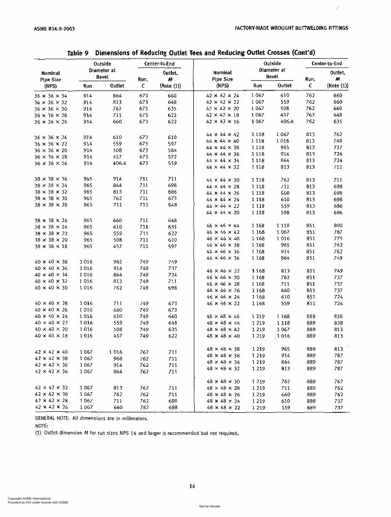
Table 9 Dimensions of Reducing Outlet Tees and Reducing Outlet Crosses (Cont'd) Outside Center-to-End
Outlet, Diameter at Bevel
Nominal Pipe Size Run, M
(NPS) Run Outlet C [Note (i)]
36 X 36 X 34
36 X 36 X 30 36 x 36 x 32
36 x 36 x 28 36 x 36 x 26
36 x 36 x 24 36 x 36 x 22 36 x 36 x 20 36 x 36 x 18 36 x 36 x 16
38 X 38 X 36 38 X 38 X 34 38 X 38 X 32 38 X 38 X 30 38 X 38 X 28
38 X 38 X 26 38 X 38 X 24 38 X 38 X 22 38 X 38 X 20 38 X 38 X 18
40 X 40 X 38 40 X 40 X 36 40 X 40 X 34 40 X 40 X 32 40 X 40 X 30
40 X 40 X 28 40 X 40 X 26 40 X 40 X 24 40 X 40 X 2 2 40 X 40 X 20 40 X 40 X 18
42 X 42 X 40 42 X 42 X 38 42 X 42 X 36 42 X 42 X 34
42 X 42 X 32 42 X 42 X 30 42 X 42 X 28 42 X 42 X 26
914 914 914 914 914
914 914 914 914 914
965 965 965 965 965
965 965 965 965 965
1016 1016 1016 1016 1016
1016 1016 1016 1016 1016 1016
1067 1067 1067 1067
1067 1067 1067 1067
864 813 762 711 660
610 559 508 457 406.4
914 864 81 3 762 71 1
660 610 559 508 457
965 914 864 81 3 762
71 1 660 610 559 508 457
1016 968 914 864
81 3 762 711 660
673 673 673 673 673
673 673 673 673 673
711 711 711 711 71 1
71 1 71 1 71 1 711 711
749 749 749 749 749
749 749 749 749 749 749
762 762 762 762
762 762 762 762
660 648 635 622 622
610 597 584 572 559
711 698 686 673 648
648 63 5 622 610 597
749 737 724 711 698
673 6 73 660 648 635 622
71 1 711 711 711
711 711 698 698
Outside Center-to-End
Outlet, Diameter at Bevel
Nominal Pipe Size Run, M W") Run Outlet C [Note (l)]
42 X 42 X 24 42 X 42 X 22 42 X 42 X 20 42 X 42 X 18 42 X 42 X 16
44 X 44 X 42 44 X 44 X 40 44 X 44 X 38 44 X 44 X 36 44 x 44 x 34 44 X 44 X 32
44 X 44 X 30 44 X 44 X 28 44 X 44 X 26 44 X 44 X 24 44 x 44 x 22 44 x 44 x 20
46 X 46 X 44 46 X 46 X 42 46 X 46 X 40 46 X 46 X 38 46 X 46 X 36 46 X 46 X 34
46 X 46 X 32 46 X 46 X 30 46 X 4.6 X 28 46 X 46 X 26 46 X 46 X 24 46 X 46 X 22
48 X 48 X 46 48 X 48 X 44 48 X 48 X 42 48 X 48 X 40
48 X 48 X 38 48 x 48 x 36 48 X 48 X 34 48 X 48 X 32
48 X 48 X 30 48 X 48 X 28 48 x 48 x 26 48 x 48 x 24 48 X 48 X 22
1067 1067 1067 1067 1067
1118 1118 1118 1118 1118 1118
1118 1118 1118 1118 1118 1118
1168 1168 1168 1168 1168 1168
1168 1168 1168 1168 1168 1168
1219 1219 1219 1219
1219 1219 1219 1219
1219 1219 1219 1219 1219
610 559 508 457 406.4
1067 1016
965 914 864 813
762 711 660 610 559 508
1118 1067 1016
965 914 864
813 762 71 1 660 610 559
1168 1118 1067 1016
965 914 864 813
762 711 660 610 559
762 762 762 762 762
813 813 813 813 813 813
813 813 813 813 813 813
851 851 851 851 851 851
851 851 851 851 851 851
889 889 889 889
889 889 889 889
889 889 889 889 889
660 660 660 648 635
762 749 737 724 724 711
711 698 698 698 686 686
800 787 775 762 762 749
749 737 737 737 724 724
838 838 813 81 3
813 787 787 787
762 762 762 737 737
GENERAL NOTE: All dimensions are in millimeters. NOTE: (1) Outlet dimension M for run sizes NPS 14 and larger is recommended but not required.
14
Copyright ASME International Provided by IHS under license with ASME
Not for ResaleNo reproduction or networking permitted without license from IHS
--```,,,-`-`,,`,,`,`,,`---

FACTORY-MADE WROUGHT BUTWELDING FITTINGS
Note square corner
ASME 816.9-2003
Enlarged Section of Lap
Table 10 Dimensions of Lap Joint Stub Ends Nominal
Pipe Size
Long Pattern Short Pattern Radius of Diameter Length, F Length, f Fillet, R of Lap, G
(N PSI Max. Min. [Notes (31, (411 [Notes (31, (411 [Note (511 [Note (611
Outside Diameter of Barrel
lh 22.8 20.5 76 3L4 28.1 25.9 76
1 35.0 32.6 102 1 '/i 43.6 41.4 102 1 lh 49.9 47.5 102
2 62.4 59.5 152 2% 75.3 72.2 152 3 91.3 88.1 152 3'h 104.0 100.8 152 4 116.7 113.5 152
5 144.3 140.5 203 6 171.3 167.5 203 8 222.1 218.3 203
10 277.2 272.3 254 12 328.0 323.1 254
51 51 51 5 1 5 1
64 64 64 76 76
76 89
102 127 152
3 35 3 43 3 5 1 5 64 6 73
8 92 8 105
10 127 10 140 11 157
11 186 13 216 13 270 13 324 13 381
14 359.9 354.8 305 152 13 413 16 411.0 405.6 305 152 13 470 18 462 456 305 152 13 533 20 514 507 305 152 13 584 22 565 558 305 152 13 641 24 616 609 305 152 13 692
GENERAL NOTES: (a) All dimensions are in millimeters. (b) See Table 2 for tolerances. (c) Service conditions and joint construction often dictate stub end length requirements. Therefore, the purchaser must
specify long or short pattern fitting when ordering. NOTES:
Gasket face finish shall be in accordance with ASME 816.5 for raised face flanges. The lap thickness T shall not be less than nominal pipe wall thickness. See Table 2 for maximum tolerance. When short pattern stub ends are used with larger flanges in Classes 300 and 600, and with most sizes in Classes 900 and higher, and when long pattern stub ends are used with larger flanges in Classes 1500 and 2500, it may be neces- sary to increase the length of the stub ends in order to avoid covering the weld with the flange. Such increases in length shall be a matter of agreement between the manufacturer and purchaser. When special facings such as tongue and groove, male and female, etc., are employed, additional lap thickness must be provided and such additional thickness shall be in addition to (not included in) the basic length F. These dimensions conform to the radius established for lap joint flanges in ASME 816.5. This dimension conforms to standard machined facings shown in ASME 816.5. The back face of the lap shall be machined to conform to the surface on which it seats. Where ring joint facings are to be applied, use dimension K as given in ASME 816.5.
15
Copyright ASME International Provided by IHS under license with ASME
Not for ResaleNo reproduction or networking permitted without license from IHS
--```,,,-`-`,,`,,`,`,,`---
ASME B16.9-2003 FACTORY-MADE WROUGHT BUTTWELDING FITTINGS
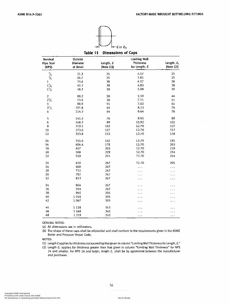
Table 11 Dimensions of Caps Nominal Outside Limiting Wall Pipe Size Diameter Length, E Thickness Length, El
( N W at Bevel [Note (111 for Length, E [Note (211
% 21.3 2 5 4.57 25 3h 26.7 2 5 3.81 2 5
1 33.4 38 4.57 38 1% 42.2 38 4.83 38 1 48.3 38 5.08 38
2 60.3 38 2% 73.0 38 3 88.9 5 1 3% 101.6 64 4 114.3 64
5 6 8
10 12
14 16 18 20 22
24 26 28 30 32
141.3 168.3 219.1 273.0 323.8
355.6 406.4 457 508 559
610 660 711 762 813
76 89
102 127 152
165 178 203 229 254
267 267 267 267 267
34 864 267 36 914 267 38 965 305 40 1 0 1 6 305 42 1 0 6 7 305
44 1 1 1 8 46 1 1 6 8 48 1 2 1 9
343 343 343
5.59 7.11 7.62 8.13 8.64
9.65 10.92 12.70 12.70 12.70
12.70 12.70 12.70 12.70 12.70
12.70 .. . .
. . .
. . .
. . .
. . .
. . .
. . .
. . .
. . .
44 5 1 64 76 76
89 102 127 1 5 2 178
191 203 229 254 254
305 ... ... . . . ... ... . . . ... ... . . . . . . . . . . . .
~~ ~ ~~
GENERAL NOTES: (a) All dimensions are in millimeters. (b) The shape of these caps shall be ellipsoidal and shall conform to the requirements given in the ASME
Boiler and Pressure Vessel Code. NOTES: (1) Length €applies forthickness not exceeding that given in column “Limiting WallThickness for Length, E.” (2) Length El applies for thickness greater than that given in column “Limiting Wall Thickness” for NPS
24 and smaller. For NPS 26 and larger, length El shall be by agreement between the manufacturer and purchaser.
16
Copyright ASME International Provided by IHS under license with ASME
Not for ResaleNo reproduction or networking permitted without license from IHS
--```,,,-`-`,,`,,`,`,,`---
FACTORY-MADE WROUGHT BUTIWELDING FITTINGS ASME 816.9-2003
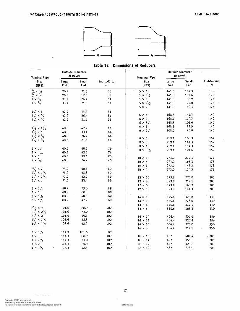
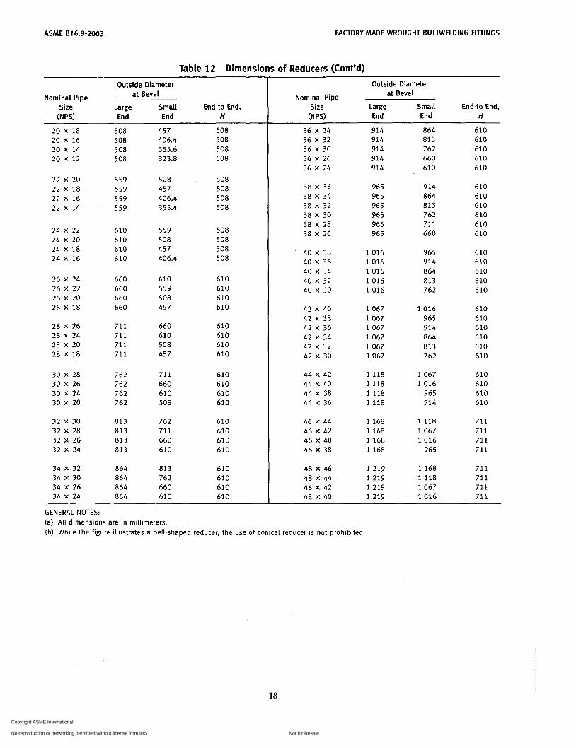
Table 12 Dimensions of Reducers Outside Diameter
at Bevel Nominal Pipe Size Large Small End-to-End,
(NPS) End End H
26.7 26.7 33.4 33.4
42.2 42.2 42.2
48.3 48.3 48.3 48.3
60.3 60.3 60.3 60.3
73.0 73.0 73.0 73.0
88.9 88.9 88.9 88.9
101.6 101.6 101.6 101.6 101.6
114.3 114.3 114.3 114.3 114.3
21.3 17.3 26.7 21.3
33.4 26.7 21.3
42.2 33.4 26.7 21.3
48.3 42.2 33.4 26.7
60.3 48.3 42.2 33.4
73.0 60.3 48.3 42.2
88.9 73.0 60.3 48.3 42.2
101.6 88.9 73.0 60.3 48.3
38 38 5 1 5 1
5 1 5 1 5 1
64 64 64 64
76 76 76 76
89 89 89 89
89 89 89 89
102 102 102 102 102
102 102 102 102 102
Outside Diameter Nominal Pipe at Bevel
Size Large Small End-to-End, (N PSI End End H
5 x 4
5 x 3
5 x 2
6 x 5 6 x 4 6 X 3'h 6 x 3 6 X 2%
8 x 6 8 x 5 8 x 4 8 X 3'/2
5 x 3l/2
5 x 2%
10 X 8 10 X 6 10 x 5 10 x 4
1 2 x 10 1 2 X 8 1 2 x 6 1 2 x 5
14 X 1 2 14 X 10 14 X 8 14 X 6
16 X 14 16 X 12 16 X 10 16 X 8
18 X 16 18 X 14 18 X 1 2 18 X 10
141.3 141.3 141.3 141.3 141.3
168.3 168.3 168.3 168.3 168.3
219.1 219.1 219.1 219.1
273.0 273.0 273.0 273.0
323.8 323.8 323.8 323.8
355.6 355.6 355.6 355.6
406.4 406.4 406.4 406.4
457 457 457 457
114.3 101.6
88.9 73.0 60.3
141.3 114.3 101.6 88.9 73.0
168.3 141.3 114.3 101.6
219.1 168.3 141.3 114.3
273.0 219.1 168.3 141.3
323.8 273.0 219.1 168.3
355.6 323.8 273.0 219.1
406.4 355.6 323.8 273.0
127 127 127 127 127
140 140 140 140 140
152 152 152 152
178 178 178 178
203 203 203 203
330 330 330 330
356 356 356 356
381 381 381 381
17
Copyright ASME International Provided by IHS under license with ASME
Not for ResaleNo reproduction or networking permitted without license from IHS
--```,,,-`-`,,`,,`,`,,`---
ASME B16.9-2003 FACTORY-MADE WROUGHT BUTTWELDING FITINGS
Outside Diameter at Bevel Nominal Pipe
Size Large Small End-to-End, W") End End H
Outside Diameter
Nominal Pipe at Bevel Size Large Small End-to-End,
(NPS) End End H
508 508 508 508
457 406.4 355.6 323.8
508 508 508 508
36 X 34 36 X 32 36 X 30 36 X 26 36 X 24
38 X 36 38 X 34 38 X 32 38 X 30 38 X 28 38 X 26
40 X 38 40 X 36 40 X 34 40 X 32 40 X 30
42 X 40 42 X 38
42 X 34 42 X 3 2
42 x 36
42 x 30
44 X 42 44 X 40 44 X 38 44 X 36
46 X 44
46 X 40 46 X 38
48 X 46 48 X 44 48 X 42 48 X 40
46 x 42
914 914 914 914 914
864 813 762 660 610
610 610 610 610 610
20 X 18 20 X 16 20 X 14 20 x 12
22 x 20 22 X 18 22 X 16 22 X 14
559 559 559 559
508 457 406.4 355.4
508 508
508 508
965 965 965 965 965 965
914 864 813 762 711 660
610 610 610 610 610 610 24 X 22
24 X 20 24 X 18 24 X 16
610 610 610 610
559 508 457 406.4
508 508 508 508
1 0 1 6 1 0 1 6 1 0 1 6 1 0 1 6 1 0 1 6
965 914 864 813 762
610 610 610 610 610
26 X 24 26 X 22 26 X 20 26 X 18
660 660 660 660
610 559 508 457
610 610 610 610 1 0 6 7
1 0 6 7 1 0 6 7 1 0 6 7 1 0 6 7 1 0 6 7
1 0 1 6 965 914 864 813 762
610 610 610 610 610 61 O
28 X 26 28 X 24 28 X 20 28 X 18
71 1 711 71 1 711
660 610 508 457
610 610 610 610
30 X 28 30 X 26 30 X 24 30 X 20
762 762 762 762
71 1 660 61 O 508
610 610 610 610
1 1 1 8 1 1 1 8 1 1 1 8 1 1 1 8
1 0 6 7 1 0 1 6
965 914
610 610 610 610
32 X 30 32 X 28 32 X 26 32 X 24
813 81 3 813 813
762 711 660 610
610 610 61 O 610
1 1 6 8 1 1 6 8 1 1 6 8 1 1 6 8
1 1 1 8 1 0 6 7 1 0 1 6
965
711 71 1 71 1 711
34 X 32 34 X 30 34 X 26 34 X 24
864 864 864 864
81 3 762 660 610
610 610 610 610
1 2 1 9 1 2 1 9 1 2 1 9 1 2 1 9
1 1 6 8 1 1 1 8 1 0 6 7 1 0 1 6
71 1 71 1 711 711
GENERAL NOTES: (a) All dimensions are in millimeters. (b) While the figure illustrates a bell-shaped reducer, the use of conical reducer is not prohibited.
18
Copyright ASME International Provided by IHS under license with ASME
Not for ResaleNo reproduction or networking permitted without license from IHS
--```,,,-`-`,,`,,`,`,,`---
ASME 816.9-2003
MANDATORY APPENDIX I INCH TABLES
This Appendix provides tables of the standard inch dimensions for fittings.
19
Copyright ASME International Provided by IHS under license with ASME
Not for ResaleNo reproduction or networking permitted without license from IHS
--```,,,-`-`,,`,,`,`,,`---
ASME 816.9-2003
CI
8 i-”
MANDATORY APPENDIX I
U c al v> .- i-
d E O .- U
U In lo
20
Copyright ASME International Provided by IHS under license with ASME
Not for ResaleNo reproduction or networking permitted without license from IHS
--```,,,-`-`,,`,,`,`,,`---
MANDATORY APPENDIX I ASME 616.9-2003
21
Copyright ASME International Provided by IHS under license with ASME
Not for ResaleNo reproduction or networking permitted without license from IHS
--```,,,-`-`,,`,,`,`,,`---
ASME 816.9-2003 MANDATORY APPENDIX I
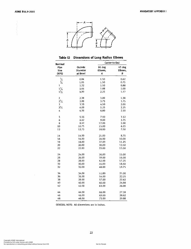
Table 12 Dimensions of Long Radius Elbows
Nominal Pipe Size
(NPs)
Outside Diameter a t Bevel
Center-to-End
90 deg Elbows,
A
2 2%
3 3 'i*
k
5 6 8
10 12
14 16 18 20 22
24 26 28 30 32
34 36 38 40 42
44 46 48
0.84 1.05 1.32 1.66 1.90
2.38 2.88 3.50 4.00 4.50
5.56 6.62
10.75 12.75
8.62
14.00 16.00 18.00 20.00 22.00
24.00 26.00 28.00 30.00 32.00
34.00 36.00 38.00 40.00 42.00
44.00 46.00 48.00
1.50 1.50 1.50 1.88 2.25
3.00 3.75 4.50 5.25 6.00
7.50 9.00
12.00 15.00 18.00
21.00 24.00 27.00 30.00 33.00
36.00 39.00 42.00 45.00 48.00
51.00 54.00 57.00 60.00 63.00
66.00 69.00 72.00
45 deg Elbows,
B
0.62 0.75 0.88 1 .o0 1.12
1.38 1.75 2.00 2.25 2.50
3.12 3.75 5.00 6.25 7.50
8.75 10.00 11.25 12.50 13.50
15.00 16.00 17.25 18.50 19.75
21.00 22.25 23.62 24.88 26.00
27.38 28.62 29.88
GENERAL NOTE: All dimensions are in inches.
22
Copyright ASME International Provided by IHS under license with ASME
Not for ResaleNo reproduction or networking permitted without license from IHS
--```,,,-`-`,,`,,`,`,,`---
MANDATORY APPENDIX I ASME 816.9-2003
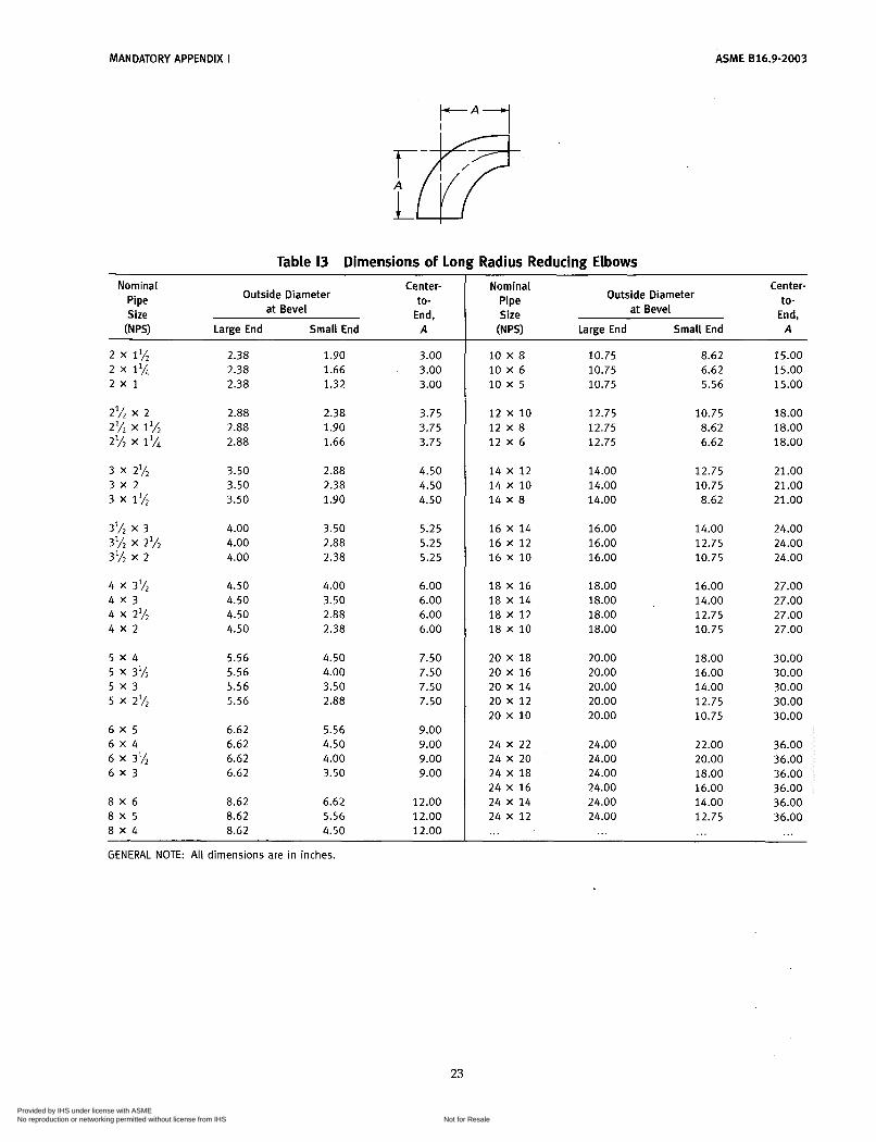
Table 13 Dimensions of Long Radius Reducing Elbows
Nominal Center- to-
End,
Outside Diameter at Bevel
Pipe Size (N PSI Large End Small End A
2 x 1% 2 x 1%
2% x 2 2% x 1% 2% x 1 %
3 x 2%
3 x 1%
3lh x 3 3lh x 2% 3 lh x 2
4 x 3 lh
4 x 2%
2 x 1
3 x 2
4 x 3
4 x 2
5 x 4
5 x 3 5 x 3lh
5 x 2%
6 x 5 6 x 4 6 x 3'h 6 x 3
8 x 6 8 x 5 8 x 4
2.38 2.38 2.38
2.88 2.88 2.88
3.50 3.50 3.50
4.00 4.00 4.00
4.50 4.50 4.50 4.50
5.56 5.56 5.56 5.56
6.62 6.62 6.62 6.62
8.62 8.62 8.62
1.90 1.66 1.32
2.38 1.90 1.66
2.88 2.38 1.90
3.50 2.88 2.38
4.00 3.50 2.88 2.38
4.50 4.00 3.50 2.88
5.56 4.50 4.00 3.50
6.62 5.56 4.50
3.00 3.00 3.00
3.75 3.75 3.75
4.50 4.50 4.50
5.25 5.25 5.25
6.00 6.00 6.00 6.00
7.50 7.50 7.50 7.50
9.00 9.00 9.00 9.00
12.00 12.00 12.00
Nominal Center- Outside Diameter
at Bevel to-
End, Pipe Size W") Large End Small End A
10 X 8 10 X 6 10 x 5
12 x 10 12 x 8 12 X 6
14 X 1 2 14 X 10 14 X 8
16 X 14 16 X 1 2 16 X 10
18 X 16 18 X 14 18 X 1 2 18 X 10
20 X 18 20 X 16 20 X 14 20 x 1 2 20 x 10
24 X 22 24 X 20 24 X 18 24 X 16 24 X 14 24 X 1 2 ...
10.75 10.75 10.75
12.75 12.75 12.75
14.00 14.00 14.00
16.00 16.00 16.00
18.00 18.00 18.00 18.00
20.00 20.00 20.00 20.00 20.00
24.00 24.00 24.00 24.00 24.00 24.00
...
8.62 6.62 5.56
10.75 8.62 6.62
12.75 10.75 8.62
14.00 12.75 10.75
16.00 14.00 12.75 10.75
18.00 16.00 14.00 12.75 10.75
22.00 20.00 18.00 16.00 14.00 12.75 ...
15.00 15.00 15.00
18.00 18.00 18.00
21.00 21.00 21.00
24.00 24.00 24.00
27.00 27.00 27.00 27.00
30.00 30.00 30.00 30.00 30.00
36.00 36.00 36.00 36.00 36.00 36.00
...
GENERAL NOTE: All dimensions are in inches.
23
Copyright ASME International Provided by IHS under license with ASME
Not for ResaleNo reproduction or networking permitted without license from IHS
--```,,,-`-`,,`,,`,`,,`---

ASME 816.9-2003 MANDATORY APPENDIX I
K
Note (2 ) A k A - ' I Ir.. Table 14 Dimensions of Long Radius Returns Table 15 Dimensions of Short Radius Elbows
Nominal Pipe Outside Center- Back- Size Diameter to-Center, to-Face,
(NP9 at Bevel O K
Nominal Pipe Size
(NPS)
Outside Diameter
at Bevel
Center- to-
End, A
0.84 1.05 1.32 1.66 1.90
3.00 3.00 3.00 3.75 4.50
1.88 2.00 2.19 2.75 3.25
1 1 IA 1 IL
1.32 1.66 1.90 2.38 2.88
1.00 1 .25 1.50 2.00 2.50
1 1 IA 1 lh
2 2%
2.38 2.88 3.50 4.00 4.50
2 2%
6.00 7.50 9.00
10.50 12.00
4.19 5.19 6.25 7.25 8.25
3
4 5 6
3% 3.50 4.00 4.50 5.56 6.62
3.00 3.50 4.00 5.00 6.00
3 3 IL 4
5 6 8
10 12
5.56 6.62 8.62
10.75 12.75
15.00 18.00 24.00 30.00 36.00
10.31 12.31 16.31 20.38 24.38
8 10 12 14 16
8.62 10.75 12.75 14.00 16.00
8.00 10.00 12.00 14.00 16.00
14 16 18 20 22 24
14.00 16.00 18.00 20.00 22.00 24.00
42.00 48.00 54.00 60.00 66.00 72.00
28.00 32.00 36.00 40.00 44.00 48.00
18 20 22 24
18.00 20.00 22.00 24.00
18.00 20.00 22.00 24.00
GENERAL NOTE: All dimensions are in inches.
GENERAL NOTE: All dimensions are in inches. NOTES: (i) See Table I l for tolerance for alignment of ends U. (2) Dimension A is equal to one-half of dimension O. (3) O and K dimensions of 2.25 in. and 1.69 in., respectively, may
be furnished for NPS at the manufacturer's option.
24
Copyright ASME International Provided by IHS under license with ASME
Not for ResaleNo reproduction or networking permitted without license from IHS
--```,,,-`-`,,`,,`,`,,`---
MANDATORY APPENDIX I ASME 816.9-2003
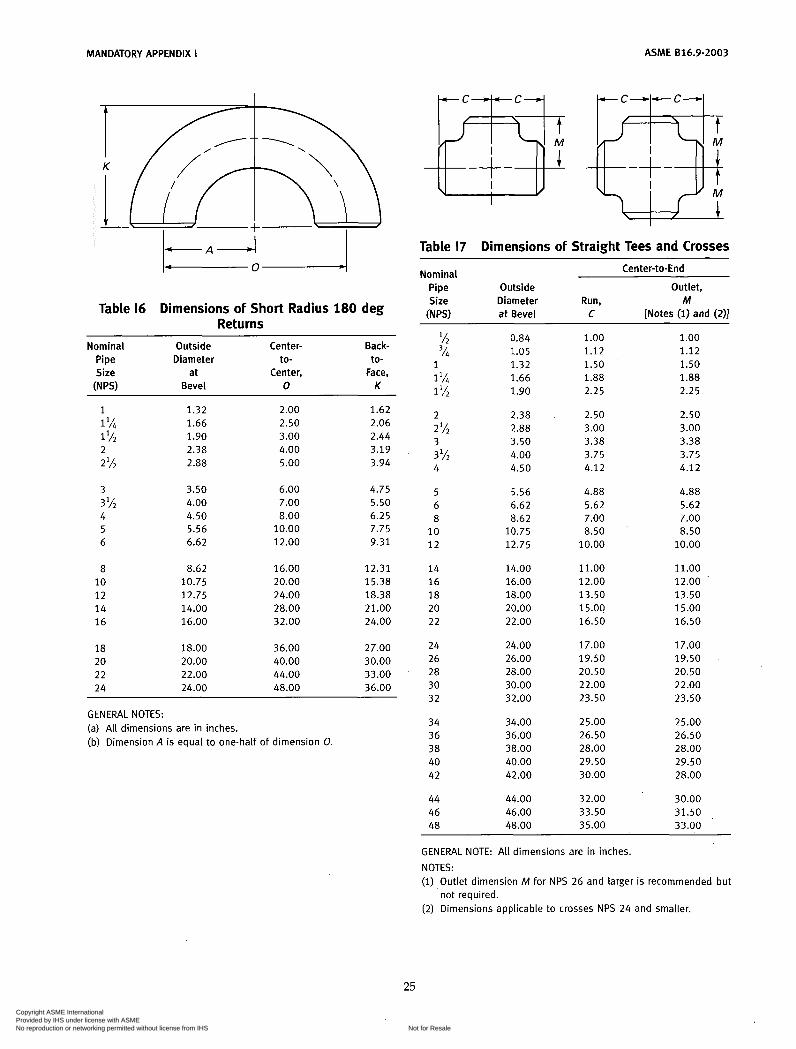
1-A-J I Table 16 Dimensions of Short Radius 180 deg
Returns ~~
Nominal Outside Center- Back- Pipe Diameter to- to- Size at Center, Face,
[NPS) Bevel O K
1 1 l/i 1 lh
2 l/2
3 l h
2
3
4 5 6
8 10 1 2 14 16
18 20 22 24
1.32 1.66 1.90 2.38 2.88
3.50 4.00 4.50 5.56 6.62
8.62 10.75 12.75 14.00 16.00
18.00 20.00 22.00 24.00
2.00 2.50 3.00 4.00 5.00
6.00 7.00 8.00
10.00 12.00
16.00 20.00 24.00 28.00 32.00
36.00 40.00 44.00 48.00
1.62 2.06 2.44 3.19 3.94
4.75 5.50 6.25 7.75 9.31
12.31 15.38 18.38 21.00 24.00
27.00 30.00 33.00 36.00
GENERAL NOTES: (a) All dimensions are in inches. (b) Dimension A is equal to one-half of dimension O.
Table 17 Dimensions of Straight Tees and Crosses Center-to-End Nominal
Pipe Outside Outlet, Size Diameter Run, M W") at Bevel C [Notes (1) and (2)]
lh 0.84 3/i 1.05
1 1.32 1 l/i 1.66 1% 1.90
2 2.38 2% 2.88 3 3.50 3 Ih 4.00 4 4.50
5 5.56 6 6.62 8 8.62
10 10.75 1 2 12.75
14 14.00 16 16.00 18 18.00 20 20.00 22 22.00
24 24.00 26 26.00 28 28.00 30 30.00 32 32.00
34 34.00 36 36.00 38 38.00 40 40.00 42 42.00
44 44.00 46 46.00 48 48.00
1.00 1.12 1.50 1.88 2.25
2.50 3.00 3.38 3.75 4.12
4.88 5.62 7.00 8.50
10.00
11.00 12.00 13.50 15.00 16.50
17.00 19.50 20.50 22.00 23.50
25.00 26.50 28.00 29.50 30.00
32.00 33.50 35.00
1.00 1.12 1.50 1.88 2.25
2.50 3.00 3.38 3.75 4.12
4.88 5.62 7.00 8.50
10.00
11.00 12.00 13.50 15.00 16.50
17.00 19.50 20.50 22.00 23.50
25.00 26.50 28.00 29.50 28.00
30.00 31.50 33.00
GENERAL NOTE: All dimensions are in inches. NOTES: (1) Outlet dimension M for NPS 26 and larger is recommended but
not required. (2) Dimensions applicable to crosses NPS 24 and smaller.
25
Copyright ASME International Provided by IHS under license with ASME
Not for ResaleNo reproduction or networking permitted without license from IHS
--```,,,-`-`,,`,,`,`,,`---
ASME 816.9-2003 MANDATORY APPENDIX I
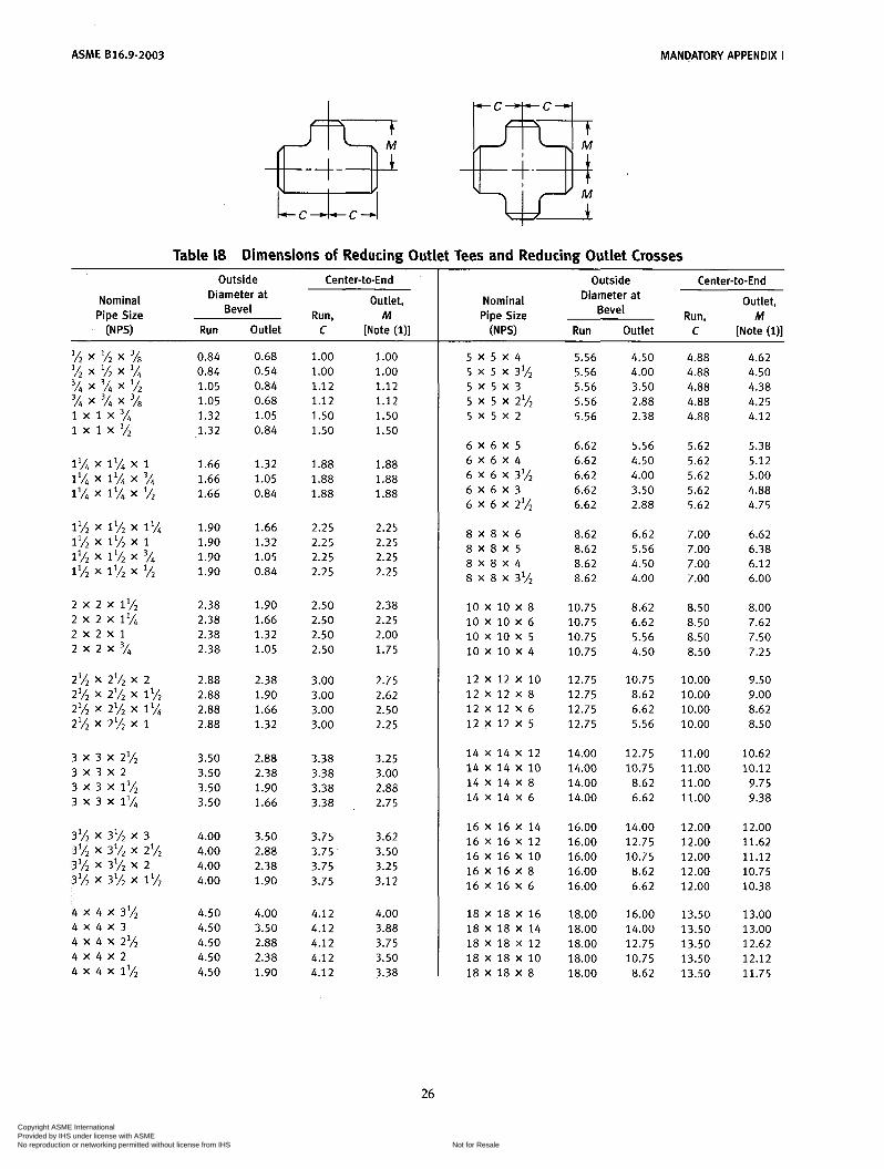
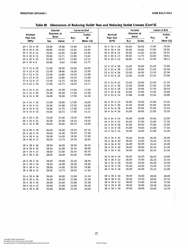
Table 18 Dimensions of Reducing Outlet Tees and Reducing Outlet Crosses
Outside Center-to-End I Outlet, Diameter at
Bevel Nominal
Pipe Size Run, M
Outside Center-to-End
Run, M Outlet, Diameter at
Bevel Nominal Pipe Size
(NP9 Run Outlet C [Note (111
2 x 2 x 1% 2 x 2 x 1%
2 X 2 X 3 / , 2 X 2 X 1
3 x 3 x 2%
3 x 3 x 1% 3 x 3 x 1%
3 X 3 X 2
4 x 4 x 31h
4 x 4 x 2%
4 x 4 x 1%
4 X 4 X 3
4 X 4 X 2
0.84 0.68 1.00 1.00 0.84 0.54 1.00 1.00 1.05 0.84 1.12 1.12 1.05 0.68 1.12 1.12 1.32 1.05 1.50 1.50 1.32 0.84 1.50 1.50
1.66 1.32 1.88 1.88 1.66 1.05 1.88 1.88 1.66 0.84 1.88 1.88
1.90 1.66 2.25 2.25 1.90 1.32 2.25 2.25 1.90 1.05 2.25 2.25 1.90 0.84 2.25 2.25
2.38 1.90 2.50 2.38 2.38 1.66 2.50 2.25 2.38 1.32 2.50 2.00 2.38 1.05 2.50 1.75
2.88 2.38 3.00 2.75 2.88 1.90 3.00 2.62 2.88 1.66 3.00 2.50 2.88 1.32 3.00 2.25
3.50 2.88 3.38 3.25 3.50 2.38 3.38 3.00 3.50 1.90 3.38 2.88 3.50 1.66 3.38 2.75
4.00 3.50 3.75 3.62 4.00 2.88 3.75 3.50 4.00 2.38 3.75 3.25 4.00 1.90 3.75 3.12
4.50 4.00 4.12 4.00 4.50 3.50 4.12 3.88 4.50 2.88 4.12 3.75 4.50 2.38 4.12 3.50 4.50 1.90 4.12 3.38
5 X 5 X 4 5.56 4.50 4.88 4.62 5 x 5 x 3'/2 5.56 4.00 4.88 4.50 5 X 5 X 3 5.56 3.50 4.88 4.38 5 x 5 x 2% 5.56 2.88 4.88 4.25 5 X 5 X 2 5.56 2.38 4.88 4.12
6 X 6 X 5 6.62 5.56 5.62 5.38 6 X 6 X 4 6.62 4.50 5.62 5.12 6 X 6 X 3'h 6.62 4.00 5.62 5.00 6 X 6 X 3 6.62 3.50 5.62 4.88 6 X 6 X 2% 6.62 2.88 5.62 4.75
8 X 8 X 6 8.62 6.62 7.00 6.62 8 X 8 X 5 8.62 5.56 7.00 6.38 8 X 8 X 4 8.62 4.50 7.00 6.1 2 8 X 8 X 3'A 8.62 4.00 7.00 6.00
8.00 10 X 10 X 8 10 X 10 X 6 10.75 6.62 8.50 7.62 10 X 10 X 5 10.75 5.56 8.50 7.50
7.25 10 X 10 X 4 10.75 4.50 8.50
12 X 1 2 X 10 12.75 10.75 10.00 9.50 9.00 12 X 12 X 8 12.75 8.62 10.00
12 X 1 2 X 6 12.75 6.62 10.00 8.62 12 X 1 2 X 5 12.75 5.56 10.00 8.50
8.62 8.50 10.75
14 X 14 X 12 14.00 12.75 11.00 10.62 14 X 14 X 10 14.00 10.75 11.00 10.12 14 X 14 X 8 14.00 8.62 11.00 9.75 14 X 14 X 6 14.00 6.62 11.00 9.38
16 X 16 X 14 16.00 14.00 12.00 12.00 16 X 16 X 12 16.00 12.75 12.00 11.62 16 X 16 X 10 16.00 10.75 12.00 11.12 16 X 16 X 8 16.00 8.62 12.00 10.75 16 X 16 X 6 16.00 6.62 12.00 10.38
18 X 18 X 16 18.00 16.00 13.50 13.00 18 X 18 X 14 18.00 14.00 13.50 13.00 18 X 18 X 1 2 18.00 12.75 13.50 12.62 18 X 18 X 10 18.00 10.75 13.50 12.12 18 X 18 X 8 18.00 8.62 13.50 11.75
26
Copyright ASME International Provided by IHS under license with ASME
Not for ResaleNo reproduction or networking permitted without license from IHS
--```,,,-`-`,,`,,`,`,,`---
MANDATORY APPENDIX I ASME 816.9-2003
Table 18 Dimensions of Reducing Outlet Tees and Reducing Outlet Crosses (Cont’d)
Outside Center-to-End
Run. M Outlet, Diameter at
Bevel Nominal Pipe Size
(NPS) Run Outlet C [Note (111
20 X 20 X 18 20 X 20 X 16 20 X 20 X 14 20 x 20 x 1 2 20 x 20 x 10 20 X 20 X 8
22 x 22 x 20 22 X 22 X 18 22 X 22 X 16 22 X 2 2 X 14 22 x 22 x 1 2 22 x 22 x 10
24 X 24 X 22 24 X 24 X 20 24 X 24 X 18
24 X 24 X 16 24 X 24 X 14 24 X 24 X 1 2 24 X 24 X 10
26 X 26 X 24 26 X 26 X 22 26 X 26 X 20
26 X 26 X 18 26 X 26 X 16 26 X 26 X 14 26 X 26 X 1 2
28 X 28 X 26 28 X 28 X 24 28 X 28 X 22 28 X 28 X 20
28 X 28 X 18 28 X 28 X 16 28 X 28 X 14 28 X 28 X 1 2
30 X 30 X 28 30 X 30 X 26 30 X 30 X 24 30 X 30 X 22 30 X 30 X 20
20.00 20.00 20.00 20.00 20.00 20.00
22.00 22.00 22.00 22.00 22.00 22.00
24.00 24.00 24.00
24.00 24.00 24.00 24.00
26.00 26.00 26.00
26.00 26.00 26.00 26.00
28.00 28.00 28.00 28.00
28.00 28.00 28.00 28.00
30.00 30.00 30.00 30.00 30.00
18.00 16.00 14.00 12.75 10.75
8.62
20.00 18.00 16.00 14.00 12.75 10.75
22.00 20.00 18.00
16.00 14.00 12.75 10.75
24.00 22.00 20.00
18.00 16.00 14.00 12.75
26.00 24.00 22.00 20.00
18.00 16.00 14.00 12.75
28.00 26.00 24.00 22.00 20.00
15.00 15.00 15.00 15.00 15.00 15.00
16.50 16.50 16.50 16.50 16.50 16.50
17.00 17.00 17.00
17.00 17.00 17.00 17.00
19.50 19.50 19.50
19.50 19.50 19.50 19.50
20.50 20.50 20.50 20.50
20.50 20.50 20.50 20.50
22.00 22.00 22.00 22.00 22.00
14.50 14.00 14.00 13.62 13.12 12.75
16.00 15.50 15.00 15.00 14.62 14.12
17.00 17.00 16.50
16.00 16.00 15.62 15.12
19.00 18.50 18.00
17.50 17.00 17.00 16.62
20.50 20.00 19.50 19.00
18.50 18.00 18.00 17.62
21.50 21.50 21.00 20.50 20.00
Center-to-End Outside
Outlet, Diameter at Bevel
Nominal Pipe Size Run, M
(NPS) Run Outlet C [Note (111
30 X 30 X 1 8 30 X 30 X 16 30 X 30 X 1 4 30 X 30 X 12 30 X 30 X 1 0
32 X 32 X 30 32 X 32 X 28 32 X 32 X 26 32 X 32 X 24
32 X 32 X 22 32 X 32 X 20 32 X 32 X 18 32 X 32 X 16 32 X 32 X 1 4
34 X 34 X 32 34 X 34 X 30 34 X 34 X 28 34 X 34 X 26
34 X 34 X 24 34 x 34 x 22 34 x 34 x 20 34 X 34 X 1 8 34 X 34 X 16
36 X 36 X 34 36 X 36 X 32 36 X 36 X 30 36 X 36 X 28 36 X 36 X 26
36 X 36 X 24 36 X 36 X 22 36 X 36 X 20 36 X 36 X 18 36 X 36 X 16
38 X 38 X 36 38 X 38 X 34 38 X 38 X 32 38 X 38 X 30 38 X 38 X 28
30.00 30.00 30.00 30.00 30.00
32.00 32.00 32.00 32.00
32.00 32.00 32.00 32.00 32.00
34.00 34.00 34.00 34.00
34.00 34.00 34.00 34.00 34.00
36.00 36.00 36.00 36.00 36.00
36.00 36.00 36.00 36.00 36.00
38.00 38.00 38.00 38.00 38.00
18.00 16.00 14.00 12.75 10.75
30.00 28.00 26.00 24.00
22.00 20.00 18.00 16.00 14.00
32.00 30.00 28.00 26.00
24.00 22.00 20.00 18.00 16.00
34.00 32.00 30.00 28.00 26.00
24.00 22.00 20.00 18.00 16.00
36.00 34.00 32.00 30.00 28.00
22.00 22.00 22.00 22.00 22.00
23.50 23.50 23.50 23.50
23.50 23.50 23.50 23.50 23.50
25.00 25.00 25.00 25.00
25.00 25.00 25.00 25.00 25.00
26.50 26.50 26.50 26.50 26.50
26.50 26.50 26.50 26.50 26.50
28.00 28.00 28.00 28.00 28.00
19.50 19.00 19.00 18.62 18.12
23.00 22.50 22.50 22.00
21.50 2 1 .o0 20.50 20.00 20.00
24.50 24.00 23.50 23.50
23.00 22.50 22.00 21.50 21.00
26.00 25.50 25.00 24.50 24.50
24.00 23.50 23.00 22.50 22.00
28.00 27.50 27.00 26.50 25.50
27
Copyright ASME International Provided by IHS under license with ASME
Not for ResaleNo reproduction or networking permitted without license from IHS
--```,,,-`-`,,`,,`,`,,`---
ASME 816.9-2003 MANDATORY APPENDIX I
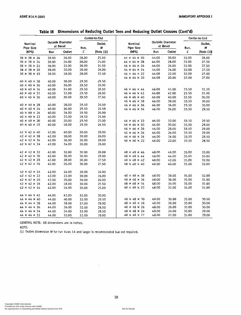
Table 18 Dimensions of Reducing Outlet Tees and Reducing Outlet Crosses (Cont’d) Center-to-End
Run, M Outlet, Outside Diameter
at Bevel Nominal Pipe Size
(N PSI Run Outlet C [Note (111
38 X 38 X 26 38 X 38 X 24 38 X 38 X 22 38 x 38 X 20 38 X 38 X 18
40 X 40 X 38 40 X 40 X 36 40 X 40 X 34 40 X 40 X 32 40 X 40 X 30
40 X 40 X 28 40 X 40 X 26 40 X 40 X 24 40 X 40 X 22 40 X 40 X 20 40 X 40 X 18
42 X 42 X 40 42 X 42 X 38 42 X 42 X 36 42 X 42 X 34
42 X 42 X 32 42 X 42 X 30 42 X 42 X 28 42 X 42 X 26
42 X 42 X 24 42 X 42 X 22 42 X 42 X 20 42 X 42 X 18 42 X 42 X 16
44 X 44 X 42 44 X 44 X 40 44 x . 4 4 X 38 44 X 44 X 36 44 x 44 X 34 44 X 44 X 32
38.00 38.00 38.00 38.00 38.00
40.00 40.00 40.00 40.00 40.00
40.00 40.00 40.00 40.00 40.00 40.00
42.00 42.00 42.00 42.00
42.00 42.00 42.00 42.00
42.00 42.00 42.00 42.00 42.00
44.00 44.00 44.00 44.00 44.00 44.00
26.00 24.00 22.00 20.00 18.00
38.00 36.00 34.00 32.00 30.00
28.00 26.00 24.00 22.00 20.00 18.00
40.00 38.00 36.00 34.00
32.00 30.00 28.00 26.00
24.00 22.00 20.00 18.00 16.00
42.00 40.00 38.00 36.00 34.00 32.00
28.00 28.00 28.00 28.00 28.00
29.50 29.50 29.50 29.50 29.50
29.50 29.50 29.50 29.50 29.50 29.50
30.00 30.00 30.00 30.00
30.00 30.00 30.00 30.00
30.00 30.00 30.00 30.00 30.00
32.00
32.00 32.00 32.00 32.00
32.00
25.50 25.00 24.50 24.00 23.50
29.50 29.00 28.50 28.00 27.50
26.50 26.50 26.00 25.50 25.00 24.50
28.00 28.00 28.00 28.00
28.00 28.00 27.50 27.50
26.00 26.00 26.00 25.50 25.00
30.00 29.50 29.00 28.50 28.50 28.00
GENERAL NOTE: All dimensions are in inches. NOTE:
Center-to-End
Run, M Outlet, Outside Diameter
at Bevel Nominal Pipe Size
(NPS1 Run Outlet C [Note (111 44 X 44 X 30 44 X 44 X 28 44 X 44 X 26 44 X 44 X 24 44 x 44 X 22 44 X 44 X 20
46 X 46 X 44 46 X 46 X 42 46 X 46 X 40 46 X 46 X 38 46 X 46 X 36 46 X 46 X 34
46 X 46 X 32 46 X 46 X 30 46 X 46 X 28 46 X 46 X 26 46 X 46 X 24 46 X 46 X 22
48 X 48 X 46 48 X 48 X 44 48 X 48 X 42 48 X 48 X 40
48 X 48 X 38 48 X 48 X 36 48 X 48 X 34 48 X 48 X 32
48 X 48 X 30 48 X 48 X 28 48 X 48 X 26 48 X 48 X 24 48 X 48 X 22
44.00 44.00 44.00 44.00 44.00 44.00
46.00 46.00 46.00 46.00 46.00 46.00
46.00 46.00 46.00 46.00 46.00 46.00
48.00 48.00 48.00 48.00
48.00 48.00 48.00 48.00
48.00 48.00 48.00 48.00 48.00
30.00 28.00 26.00 24.00 22.00 20.00
44.00 42.00 40.00 38.00 36.00 34.00
32.00 30.00 28.00 26.00 24.00 22.00
46.00 44.00 42.00 40.00
38.00 36.00 34.00 32.00
30.00 28.00 26.00 24.00 22.00
32.00 32.00 32.00 32.00 32.00 32.00
33.50 33.50 33.50 33.50 33.50 33.50
33.50 33.50 33.50 33.50 33.50 33.50
35.00 35.00 35.00 35.00
35.00 35.00 35.00 35.00
35.00 35.00 35.00 35.00 35.00
28.00 27.50 27.50 27.50 27.00 27.00
31.50 31.00 30.50 30.00 30.00 29.50
29.50 29.00 29.00 29.00 28.50 28.50
33.00 33.00 32.00 32.00
32.00 31.00 31.00 31.00
30.00 30.00 30.00 29.00 29.00
(1) Outlet dimension M for run sizes 14 and larger i s recommended but not required.
Copyright ASME International Provided by IHS under license with ASME
Not for ResaleNo reproduction or networking permitted without license from IHS
--```,,,-`-`,,`,,`,`,,`---

MANDATORY APPENDIX I ASME 816.9-2003
Note square corner
I - F 4 Enlarged Section
of Lap
Table 19 Dimensions of Lap Joint Stub Ends Nominal
Pipe Size
Long Pattern Short Pattern Radius of Diameter Length, F Length, F Fillet, R of Lap, G
Outside Diameter of Barrel
lh 0.896 0.809 3.00 3h 1.106 1.019 3.00 1 1.376 1.284 4.00 1 % 1.716 1.629 4.00 1 lh 1.965 1.869 4.00
2 2.456 2.344 6.00 2% 2.966 2.844 6.00 3 3.596 3.469 6.00 3lh 4.096 3.969 6.00 4 4.593 4.469 6.00
5 5.683 5.532 8.00 6 6.743 6.594 8.00 8 8.743 8.594 8.00 10 10.913 10.719 10.00 12 12.913 12.719 10.00
14 14.170 13.969 12.00 16 16.180 15.969 12.00 18 18.190 17.969 12.00 20 20.240 19.969 12.00 22 22.240 21.969 12.00 24 24.240 23.969 12.00
2.00 2.00 2.00 2.00 2.00
2.50 2.50 2.50 3.00 3.00
3.00 3.50 4.00 5.00 6.00
6.00 6.00 6.00 6.00 6.00 6.00
0.12 1.38 0.12 1.69 0.12 2.00 0.19 2.50 0.25 2.88
0.31 3.62 0.31 4.12 0.38 5.00 0.38 5.50 0.44 6.19
0.44 7.31 0.50 8.50 0.50 10.62 0.50 12.75 0.50 15.00
0.50 16.25 0.50 18.50 0.50 21.00 0.50 23.00 0.50 25.25 0.50 27.25
GENERAL NOTES: (a) All dimensions are in inches. (b) See Table Il for tolerances. (c) Service conditions and joint construction often dictate stub end length requirements. Therefore, the purchaser must
specify long or short pattern fitting when ordering. NOTES:
Gasket face finish shall be in accordance with ASME 816.5 for raised face flanges. The lap thickness T shall not be less than nominal pipe wall thickness. See Table Il for tolerance. When short pattern stub ends are used with larger flanges in Classes 300 and 600, and with most sizes in Classes 900 and higher, and when long pattern stub ends are used with larger flanges in Classes 1500 and 2500, it may be neces- sary to increase the length of the stub ends in order to avoid covering the weld with the flange. Such increases in lengîh shall be a matter of agreement between the manufacturer and purchaser. When special facings such as tongue and groove, male and female, etc., are employed, additional lap thickness must be provided and such additional thickness shall be in addition to (not included in) the basic length F. These dimensions conform to the radius established for lap joint flanges in ASME 816.5. This dimension conforms to standard machined facings shown in ASME 816.5. The back face of the lap shall be machined to conform to the surface on which it seats. Where ring joint facings are to be applied, use dimension Kas given in ASME 816.5.
29
Copyright ASME International Provided by IHS under license with ASME
Not for ResaleNo reproduction or networking permitted without license from IHS
--```,,,-`-`,,`,,`,`,,`---

ACME 816.9-2003 MANDATORY APPENDIX I
Table 110 Dimensions of Caps Nominal Outside Limiting Wall Pipe Size Diameter Length, E Thickness Length, El
íN PSI at Bevel [Note (111 for Length, E [Note (211
lh 0.84 1.00 3/i 1.05 1.00 1 1.32 1.50 1% 1.66 1.50 1 lh 1.90 1.50
2 2.38 1.50 2% 2.88 1.50 3 3.50 2.00 3 l h 4.00 2.50 4 4.50 2.50
5 6 8
10 1 2
14 16 18 20 2 2
24 26 28 30 32
34 36 38 40 42
5.56 6.62 8.62
10.75 12.75
14.00 16.00 18.00 20.00 22.00
24.00 26.00 28.00 30.00 32.00
3.00 3.50 4.00 5.00 6.00
6.50 7.00 8.00 9.00
10.00
10.50 10.50 10.50 10.50 10.50
34.00 10.50 36.00 10.50 38.00 12.00 40.00 12.00 42.00 12.00
0.18 0.1 5 0.18 0.19 0.20
1.00 1.00 1.50 1.50 1.50
0.22 0.28 0.30 0.32 0.34
0.38 0.43 0.50 0.50 0.50
0.50 0.50 0.50 0.50 0.50
0.50
. . .
...
. . .
. . .
. . .
. . .
1.75 2.00 2.50 3.00 3.00
3.50 4.00 5.00 6.00 7.00
7.50 8.00 9.00
10.00 10.00
12.00 .. .. ... ...
...
...
44 44.00 13.50 . . . . . . 46 46.00 13.50 . . . . . . 48 48.00 13.50 . . . . . .
GENERAL NOTES: (a) All dimensions are in inches. (b) The shape of these caps shall be ellipsoidal and shall conform to the shape requirements as given
in the ASME Boiler and Pressure Vessel Code. NOTES: (1) Length €applies forthickness not exceedingthat given in column “Limiting WallThickness for Length, E.” (2) Length El applies for thickness greater than that given in column “Limiting Wall Thickness” for NPS
24 and smaller. For NPS 26 and larger, length El shall be by agreement between the manufacturer and purchaser.
30
Copyright ASME International Provided by IHS under license with ASME
Not for ResaleNo reproduction or networking permitted without license from IHS
--```,,,-`-`,,`,,`,`,,`---
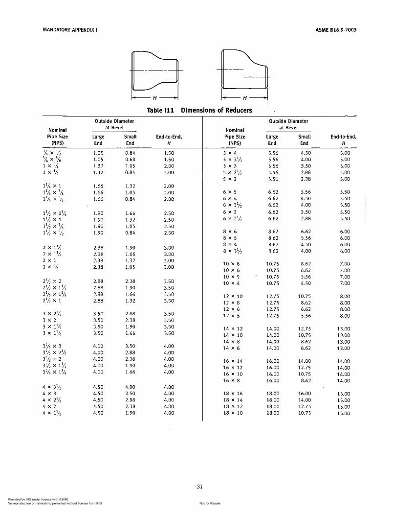
MANDATORY APPENDIX i ASME 816.9-2003
I + I 4 4
Table 111 Dimensions of Reducers Outside Diameter
at Bevel Nominal Pipe Size Large Small End-to-End,
(N PSI End End H
1.05 1.05 1.32 1.32
1.66 1.66 1.66
1.90 1.90 1.90 1.90
2.38 2.38 2.38 2.38
2.88 2.88 2.88 2.88
3.50 3.50 3.50 3.50
4.00 4.00 4.00 4.00 4.00
4.50 4.50 4.50 4.50 4.50
0.84 0.68 1.05 0.84
1.32 1.05 0.84
1.66 1.32 1.05 0.84
1.90 1.66 1.32 1.05
2.38 1.90 1.66 1.32
2.88 2.38 1.90 1.66
3.50 2.88 2.38 1.90 1.66
4.00 3.50 2.88 2.38 1.90
1.50 1.50 2.00 2.00
2.00 2.00 2.00
2.50 2.50 2.50 2.50
3.00 3.00 3.00 3.00
3.50 3.50 3.50 3.50
3.50 3.50 3.50 3.50
4.00 4.00 4.00 4.00 4.00
4.00 4.00 4.00 4.00 4.00
Outside Diameter at Bevel Nominal
Pipe Size Large Small End-to-End, ( N W End End H
5 x 4
5 x 3
5 x 2
6 x 5 6 x 4 6 X 3% 6 x 3 6 X 2%
8 x 6 8 x 5 8 x 4 8 X 3'/2
10 X 8 10 X 6 10 x 5 10 x 4
12 x 10 12 X 8 12 X 6 1 2 x 5
14 X 12 14 X 10 14 X 8 14 X 6
16 X 14 16 X 12 16 X 10 16 X 8
18 X 16 18 X 14 18 X 1 2 18 X 10
5 x 31h
5 x 2%
5.56 5.56 5.56 5.56 5.56
6.62 6.62 6.62 6.62 6.62
8.62 8.62 8.62 8.62
10.75 10.75 10.75 10.75
12.75 12.75 12.75 12.75
14.00 14.00 14.00 14.00
16.00 16.00 16.00 16.00
18.00 18.00 18.00 18.00
4.50 4.00 3.50 2.88 2.38
5.56 4.50 4.00 3.50 2.88
6.62 5.56 4.50 4.00
8.62 6.62 5.56 4.50
10.75 8.62 6.62 5.56
12.75 10.75 8.62 6.62
14.00 12.75 10.75
8.62
16.00 14.00 12.75 10.75
5.00 5.00 5.00 5.00 5.00
5.50 5.50 5.50 5.50 5.50
6.00 6.00 6.00 6.00
7.00 7.00 7.00 7.00
8.00 8.00 8.00 8.00
13.00 13.00 13.00 13.00
14.00 14.00 14.00 14.00
15.00 15.00 15.00 15.00
31 Copyright ASME International Provided by IHS under license with ASME
Not for ResaleNo reproduction or networking permitted without license from IHS
--```,,,-`-`,,`,,`,`,,`---
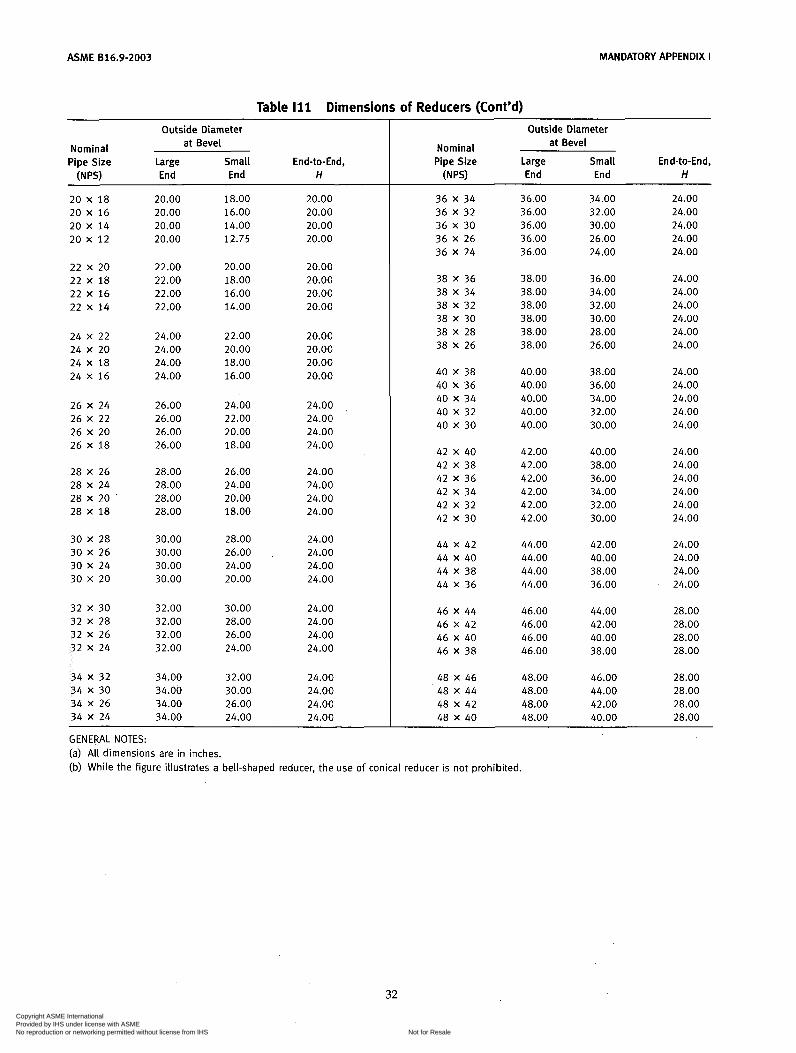
ACME 816.9-2003 MANDATORY APPENDIX I
Outside Diameter
Nominal at Bevel Pipe Size Large Small End-to-End,
(N PSI End End H
Outside Diameter
Nominal at Bevel Pipe Size Large Small End-to-End, W") End End H
20.00 20.00 20.00 20.00
34 x 32 34.00 32.00 24.00 34 X 30 34.00 30.00 24.00 34 X 26 34.00 26.00 24.00 34 X 24 34.00 24.00 24.00
18.00 16.00 14.00 12.75
48 X 46 48.00 46.00 28.00 48 X 44 48.00 44.00 28.00 48 X 42 48.00 42.00 28.00 48 X 40 48.00 40.00 28.00
20.00 20.00 20.00 20.00
36 X 34 36 X 32 36 X 30 36 X 26 36 X 24
36.00 36.00 36.00 36.00 36.00
34.00 32.00 30.00 26.00 24.00
24.00 24.00 24.00 24.00 24.00
20 x 18 20 X 16 20 x 14 20 x 12
22 x 20 22 x 18 22 X 16 22 x 14
22.00 22.00 22.00 22.00
20.00 18.00 16.00 14.00
20.00 20.00 20.00 20.00
38.00 38.00 38.00 38.00 38.00 38.00
24.00 24.00 24.00 24.00 24.00 24.00
38 X 36 38 X 34 38 X 32 38 X 30 38 X 28 38 X 26
36.00 34.00 32.00 30.00 28.00 26.00
24 X 22 24 X 20 24 X 18 24 X 16
24.00 24.00 24.00 24.00
22.00 20.00 18.00 16.00
20.00 20.00 20.00 20.00 40 X 38
40 X 36 40 X 34 40 X 32 40 X 30
40.00 40.00 40.00 40.00 40.00
38.00 36.00 34.00 32.00 30.00
24.00 24.00 24.00 24.00 24.00
26 X 24 26 X 22 26 X 20 26 x 18
28 X 26 28 X 24 28 X 20 28 X 1 8
26.00 26.00 26.00 26.00
24.00 22.00 20.00 18.00
24.00 24.00 24.00 24.00
42 X 40 42.00 40.00 24.00
28.00 26.00 24.00 28.00 24.00 24.00 28.00 20.00 24.00 28.00 18.00 24.00
42 X 38 42.00 38.00 24.00 42 X 36 42.00 36.00 24.00 42 X 34 42.00 34.00 24.00 42 X 32 42.00 32.00 24.00 42 X 30 42.00 30.00 24.00
44 X 42 44.00 42.00 24.00 44 X 40 44.00 40.00 24.00 44 X 38 44.00 38.00 24.00 44 X 36 44.00 36.00 24.00
46 X 44 46.00 44.00 28.00 46 X 42 46.00 42.00 28.00 46 X 40 46.00 40.00 28.00 46 X 38 46.00 38.00 28.00
30 X 28 30.00 28.00 24.00 30 X 26 30.00 26.00 24.00 30 X 24 30.00 24.00 24.00 30 X 20 30.00 20.00 24.00
32 X 30 32.00 30.00 24.00 32 X 28 32.00 28.00 24.00 32 X 26 32.00 26.00 24.00 32 X 24 32.00 24.00 24.00
32 Copyright ASME International Provided by IHS under license with ASME
Not for ResaleNo reproduction or networking permitted without license from IHS
--```,,,-`-`,,`,,`,`,,`---

ASME 816.9-2003
MAN DATO RY AP P E N D IX I I REFERENCES
The following is a list of standards and specifications referenced in this Standard, showing the year of approval.
ACME B16.5-2003, Pipe Flanges and Flanged Fittings
ACME B16.25-1997, Buttwelding Ends ACME B16.49-2000, Factory-Made Wrought Steel Butt-
welding Induction Bends for Transportation and Dis- tribution Systems
NPS '/2 Through NPS 24 Metric/Inch Standard
ACME B31, Code for Pressure Piping ACME B36.10M-2000, Welded and Seamless Wrought
ACME B36.19M-l985(R1994), Stainless Steel Pipe ACME BPVC-2001, ACME Boiler and Pressure Vessel
Code Publisher: The American Society of Mechanical Engi-
neers (ACME International), Three Park Avenue, New York, NY 10016-5990; Order Department: 22 Law Drive, Box 2300, Fairfield, NJ 07007-2300
ASTM A 234-02, Standard Specification for Piping Fit- tings of Wrought Carbon Steel and Alloy Steel for Moderate and High Temperature Service
ASTM A 403-02, Standard Specification for Wrought Austenitic Stainless Steel Piping Fittings
ASTM A 420-02, Standard Specification for Piping Fit- tings of Wrought Carbon Steel and Alloy Steel for Low-Temperature Service
Steel Pipes
ASTM A 815/A 815M-O1a, Standard Specification for Wrought Ferritic, Ferritic/Austenitic and Martensitic Stainless Steel Piping Fittings
ASTM B 361-02, Standard Specification for Factory- Made Wrought Aluminum and Aluminum-Alloy Welding Fittings
ASTM B 363-02, Standard Specification for Seamless and Welded Unalloyed Titanium and Titanium Alloy Welding Fittings
ASTM B 366-01e1, Standard Specification for Factory- Made Wrought Nickel and Nickel Alloy Fittings
ASTM E 29-02, Standard Practice for Using Significant Digits in Test Data to Determine Conformance With Specifications
Publisher: American Society for Testing and Materials (ASTM), 100 Barr Harbor Drive, West Conshohocken,
IS0 6708:1995, Pipework Components - Definition and Selection of DN (Nominal Size)
IS0 9000:2000, Quality Management Systems - Funda- mentals and Vocabulary
I S 0 9001:2000, Quality Management Systems - Requirements
IS0 9004:2000, Quality Management Systems - Guide- lines for Performance Improvements
Publisher: International Organization for Standardiza- tion (ISO), 1 rue de Varembé, Case Postale 56, CH- 1211, Genève 20, Switzerland/Suisse
PA 19428-2959
33
Copyright ASME International Provided by IHS under license with ASME
Not for ResaleNo reproduction or networking permitted without license from IHS
--```,,,-`-`,,`,,`,`,,`---

ASME 816.9-2003
NONMANDATORY APPENDIX A QUALITY SYSTEM PROGRAM
The products manufactured in accordance with this Standard shall be produced under a Quality System Program following the principles of an appropriate stan- dard from the IS0 9000 series.' A determination of the need for registration and/or certification of the product
The series is also available from the American National Stan- dards Institute (ANSI) and the American Society for Quality (ASQ) as American National Standards that are identified by a prefix " Q replacing the prefix "150." Each standard of the series is listed in Mandatory Appendix II.
manufacturer's quality system by an independent orga- nization shall be the responsibility of the manufacturer. The detailed documentation demonstrating program compliance shall be available to the purchaser at the manufacturer's facility. A written summary description of the program utilized by the product manufacturer shall be available to the purchaser upon request. The product manufacturer is defined as the entity whose name or trademark appears on the product in accordance with the marking or identification requirements of this Standard.
34
Copyright ASME International Provided by IHS under license with ASME
Not for ResaleNo reproduction or networking permitted without license from IHS
--```,,,-`-`,,`,,`,`,,`---
ASME Bi 6.9-2003 INTERPRETATIONS
Replies to Technical Inquiries January 2002 through October 2002
FOREWORD
This publication includes all of the written replies issued between the indicated dates by the Secretary, speaking for the ASME B16 Committee, Standardization of Valves, Flanges, Fittings, and Gaskets, to inquiries concerning interpretations of technical aspects of ACME B16.9, Factory- Made Wrought Buttwelding Fittings.
These replies are taken verbatim from the original letters except for a few typographical corrections and some minor editorial corrections made for the purpose of improved clarity. In some few instances, a review of the interpretation revealed a need for corrections of a technical nature; in these cases, a corrected interpretation follows immediately after the original reply.
These interpretations were prepared in accordance with the accredited ACME procedures. ACME procedures provide for reconsideration of these interpretations when or if additional information is available that the inquirer believes might affect the interpretation. Further, persons aggrieved by this interpretation may appeal to the cognizant ACME Committee or Subcommittee. ACME does not "approve," "certify," "rate," or "endorse" any item, construction, proprietary device, or activity.
1-1
Copyright ASME International Provided by IHS under license with ASME
Not for ResaleNo reproduction or networking permitted without license from IHS
--```,,,-`-`,,`,,`,`,,`---
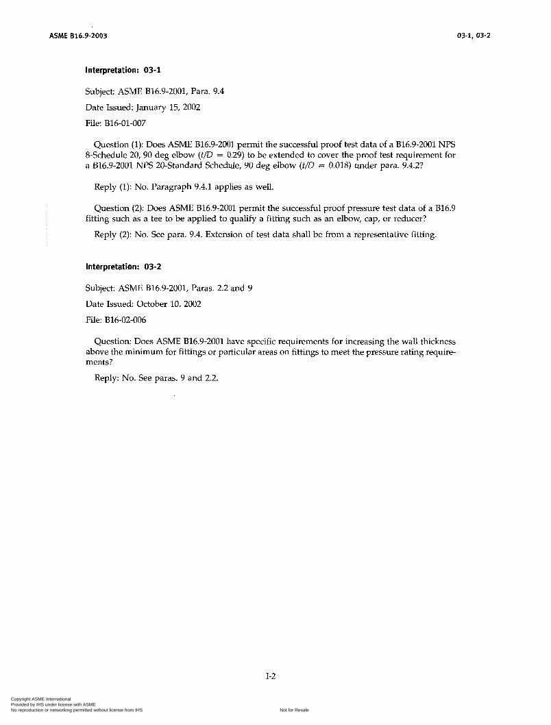
ASME 816.9-2003 03-1, 03-2
Interpretation: 03-1
Subject: ACME B16.9-2001, Para. 9.4
Date Issued: January 15, 2002
File: B16-01-007
Question (1): Does ASME B16.9-2001 permit the successful proof test data of a B16.9-2001 NPS 8-Schedule 20,90 deg elbow (t/D = 0.29) to be extended to cover the proof test requirement for a B16.9-2001 NPS 20-Standard Schedule, 90 deg elbow (t/o = 0.018) under para. 9.4.2?
Reply (1): No. Paragraph 9.4.1 applies as well.
Question (2): Does ASME B16.9-2001 permit the successful proof pressure test data of a B16.9
Reply (2): No. See para. 9.4. Extension of test data shall be from a representative fitting.
fitting such as a tee to be applied to qualify a fitting such as an elbow, cap, or reducer?
Interpretation: 03-2
Subject: ACME 816.9-2001, Paras. 2.2 and 9
Date Issued: October 10, 2002
File: 816-02-006
Question: Does ASME 816.9-2001 have specific requirements for increasing the wall thickness above the minimum for fittings or particular areas on fittings to meet the pressure rating require- ments?
Reply: No. See paras. 9 and 2.2.
1-2
Copyright ASME International Provided by IHS under license with ASME
Not for ResaleNo reproduction or networking permitted without license from IHS
--```,,,-`-`,,`,,`,`,,`---
AMERICAN NATIONAL STANDARDS FOR PIPING. PIPE FLANGES. FITTINGS. AND VALVES
Scheme for the Identification of Piping Systems ................................................................... A13.1-1996 Pipe Threads, General Purpose (Inch) .................................................................. B1.20.1-1983 (R1992) Dryseal Pipe Threads (Inch) .......................................................................... 81.20.3-1976 (R1998) Cast Iron Pipe Flanges and Flanged Fittings: Classes 25, 125, and 250 ............................................... .B1 6.1'1998 Malleable Iron Threaded Fittings: Classes 150 and 300 ............................................................ .B16. 3.1998 Gray Iron Threaded Fittings: Classes 125 and 250 ................................................................ .B16. 4.1998 Pipe Flanges and Flanged Fittings NPS 'h Through NPS 24 Metric/lnch Standard ....................................... .B16. 5.2003 Factory-Made Wrought Buttwelding Fittings ....................................................................... B16.9-2003 Face-to-Face and End-to-End Dimensions of Valves .............................................................. .B16.1 0.2000 Forged Fittings, Socket-Welding and Threaded .................................................................. .616.1 1.2001 Cast Iron Threaded Drainage Fittings ........................................................................... B16.12-1998 Ferrous Pipe Plugs, Bushings. and Locknuts with Pipe Threads .................................................... .B16.1 4.1991 Cast Bronze Threaded Fittings: Classes 125 and 250 ...................................................... .B16.1 5.1985 (R1994) Cast Copper Alloy Solder Joint Pressure Fittings ................................................................. .B16.1 8.2001 Metallic Gaskets for Pipe Flanges: Ring.joint, CpiraLWound, and Jacketed ............................................ .616.2 0.1998 Nonmetallic Flat Gaskets for Pipe Flanges ...................................................................... .B16.2 1.1992 Wrought Copper and Copper Alloy Solder Joint Pressure Fittings .................................................... .B16.2 2.2001 Cast Copper Alloy Solder Joint Drainage Fittings: DWV ............................................................ .B16.2 3.2002 Cast Copper Alloy Pipe Flanges and Flanged Fittings: Class 150, 300, 400, 600, 900, 1500, and 2500 .................... .B16.2 4.2001 Buttwelding Ends ........................................................................................... B16.25-1997 Cast Copper Alloy Fittings for Flared Copper Tubes ............................................................... .B16.2 6.1988 Wrought Steel Buttwelding Short Radius Elbows and Returns ...................................................... .B16.2 8.1994 Wrought Copper and Wrought Copper Alloy Solder Joint Drainage Fittings - DWV ...................................... .B16.2 9.2001 Manually Operated Metallic Gas Valves for Use in Gas Piping Systems up to 125 psig (Sizes 'h Through 2) . . . . . . . . . . . . . . . . .B16.3 3.1990 Valves - Flanged, Threaded, and Welding End .................................................................. .B16.3 4.1996 Orifice Flanges ............................................................................................. B16.36-1996 Large Metallic Valves for Gas Distribution (Manually Operated, NPS 2% to 12, 125 psig Maximum) ............... .B16.3 8.1985 (R1994) Malleable Iron Threaded Pipe Unions ......................................................................... .B16.3 9.1998 Manually Operated Thermoplastic Gas Shutoffs and Valves in Gas Distribution Systems ................................ .B16.4 0.2002 Functional Qualification Requirements for Power Operated Active Valve Assemblies for Nuclear Power Plants ........ .B16.4 1.1983 (R1989) Ductile Iron Pipe Flanges and Flanged Fittings, Classes 150 and 300 ............................................... .B16.4 2.1998 Manually Operated Metallic Gas Valves for Use in Above Ground Piping Systems Up To 5 psi ........................... .B16.4 4.2002 Cast Iron Fittings for Sovent@ Drainage Systems .................................................................. B16.45-1998 Large Diameter Steel Flanges (NPS 26 Through NPS 60) .......................................................... .B16.4 7.1996 Steel Line Blanks ........................................................................................... B16.48-1997 Factory-Made Wrought Steel Buttwelding Induction Bends for Transportation and Distribution Systems .................... .B16.4 9.2000 Wrought Copper and Copper Alloy Braze-Joint Pressure Fittings .................................................... .B16.5 0.2001 Power Piping ............................................................................................... 831.1-2001 Fuel Gas Piping (not an ANSI standard) ......................................................................... .B31. 2.1968 Process Piping .............................................................................................. B31.3~2002 Pipeline Transportation Systems for Liquid Hydrocarbons and Other Liquids ........................................... .B31. 4.2002 Refrigeration Piping and Heat Transfer Components ............................................................... .B31. 5.2001 Gas Transmission and Distribution Piping Systems ................................................................ B31.8-1999 Building Services Piping ...................................................................................... B3i.9-1996 Slurry Transportation Piping Systems ........................................................................... B31.11-2002 Manual for Determining the Remaining Strength of Corroded Pipelines ................................................ B31G-1991 Welded and Seamless Wrought Steel Pipe .................................................................... B36.1OM-2000 Stainless Steel Pipe ............................................................................... B36.19M-1985 (R1994) Self-operated and Power-Operated Safety-Related Valves Functional Specification Standard ...................... .N278. 1.1975 (R1992)
The ASME Publications Catalog shows a complete list of all the Standards published by the Society . For a complimentary catalog. or the latest information about our publications. call 1-800-THE-ASME (1 .800.843.2763) .
Copyright ASME International Provided by IHS under license with ASME
Not for ResaleNo reproduction or networking permitted without license from IHS
--```,,,-`-`,,`,,`,`,,`---

ASME Services
ASME is committed to developing and delivering technical information. At ASME's Information Central, we make evely effort to answer your questions and expedite your orders. Our representatives are ready to assist you in the following areas:
ASME Press Codes & Standards Credit Card Orders IMechE Publications Meetings & Conferences Member Dues Status
Member Services & Benefits Other ASME Programs Paym en t i nq u iries Professional Development
Short Courses Publications
Public Information Self-study Courses Ship ping in format ion Su bscriptions/lournals/Magazines Symposia Volumes Technical Papers
How can you reach us? It's easier than ever!
There are four options for making inquiries* or placing orders. Simply mail. phone, fax, or E-mail us and an information Central representative will handle your request.
Mail Call Toll Free Fax-24 hours E-Mail-24 hours ASME US & Canada: 800-THE-ACME 973-882-1 71 7 [email protected]
Fairfield, New Jersey Mexico: 95-800-THE-ACME 22 Law Drive, Box 2900 (800-843-2763) 973-882-51 55
07007-2900 (95-800-843-2763) Universal: 973-882-1167
* Information Central staff are not permitted to answer inquiries about the technical content of this code or standard. Information as to whether or not technical inquiries are issued to this code or standard is shown on the copyright page. All technical inquiries must be submitted in writing to the staff secretary. Additional procedures for inquiries may be listed within.
Copyright ASME International Provided by IHS under license with ASME
Not for ResaleNo reproduction or networking permitted without license from IHS
--```,,,-`-`,,`,,`,`,,`---

Copyright ASME International Provided by IHS under license with ASME
Not for ResaleNo reproduction or networking permitted without license from IHS
--```,,,-`-`,,`,,`,`,,`---

1 ISBN 0-7938-2867-0
9 780791 828670
~
J 1 0903
Copyright ASME International Provided by IHS under license with ASME
Not for ResaleNo reproduction or networking permitted without license from IHS
--```,,,-`-`,,`,,`,`,,`---