Embed Size (px)
Citation preview
B10: Stormwater Drainage City of Sydney Town Hall House 456 Kent Street Sydney NSW 2000
Construction

Sydney Streets Technical Specifications
B10. Stormwater Drainage
Version 4: June 2016 Page i
Table of Contents
10.1 Scope ................................................................................................................... 1
10.2 Standard and Guidelines .................................................................................... 1
10.3 Stormwater Drainage Design ............................................................................. 3
10.4 Materials .............................................................................................................. 3 10.4.1 Pipes ................................................................................................................ 3 10.4.1.1 Reinforced Concrete Pipes (RCP) .................................................................... 3 10.4.1.2 Fibre Reinforced Concrete (FRC) Pipes ........................................................... 3 10.4.1.3 Plastic Pipes ..................................................................................................... 3 10.4.1.4 Subsoil Drainage and Agricultural Pipes .......................................................... 4 10.4.1.4.1 Slotted UPVC for Raingardens ......................................................................... 4 10.4.1.5 Special Pipes.................................................................................................... 4 10.4.1.5.1 Permeable concrete pipes................................................................................ 4 10.4.1.5.2 Prefabricated Fittings ....................................................................................... 4 10.4.1.6 Box Culverts ..................................................................................................... 4 10.4.1.6.1 Precast Reinforced Concrete ............................................................................ 4 10.4.1.6.2 Cast In-situ Concrete ........................................................................................ 4 10.4.1.6.3 Jointing Material ............................................................................................... 5 10.4.1.7 Concrete, Reinforcement and Epoxy Grout ...................................................... 5 10.4.2 Fill and Pipe Support Material .......................................................................... 5 10.4.2.1 Natural Material ................................................................................................ 5 10.4.2.2 Recycled Material ............................................................................................. 5 10.4.3 Stormwater Pits ................................................................................................ 6 10.4.4 Precast Structures ............................................................................................ 6 10.4.5 Stone Lintels ..................................................................................................... 6 10.4.6 Stormwater Grates, Frames and Covers ........................................................... 6 10.4.7 Waterproofing................................................................................................... 7 10.4.8 Raingardens ..................................................................................................... 7 10.4.8.1 Lining Materials ................................................................................................ 7 10.4.8.1.1 Unreinforced Polypropylene ............................................................................. 7 10.4.8.1.2 Shotcrete .......................................................................................................... 7 10.4.8.2 Drainage Layer ................................................................................................. 7 10.4.8.3 Transition Layer ................................................................................................ 8 10.4.8.4 Bio Filtration Layer ............................................................................................ 8 10.4.8.5 Gravel Mulch .................................................................................................... 8 10.4.8.6 Submerged Zone Layer .................................................................................... 8
10.5 Supply .................................................................................................................. 9 10.5.1 Quality .............................................................................................................. 9 10.5.2 Unloading, Handling and Storage .................................................................... 9
10.6 Drainage Construction ........................................................................................ 9 10.6.1 Trench for Drainage .......................................................................................... 9 10.6.1.1 General ............................................................................................................ 9 10.6.1.2 Width of Excavation ........................................................................................ 10 10.6.1.3 Allowance for Bedding ................................................................................... 10 10.6.1.4 Pipe Cover ...................................................................................................... 10 10.6.2 Pipe Bedding and Side Support ..................................................................... 11
Sydney Streets Technical Specifications
B10. Stormwater Drainage
Version 4: June 2016 Page ii
10.6.3 Laying and Jointing ........................................................................................ 11 10.6.3.1 Pipes .............................................................................................................. 11 10.6.3.2 Box Culverts ................................................................................................... 11 10.6.4 Subsoil Pipes in Trench .................................................................................. 11 10.6.5 Backfilling ....................................................................................................... 12 10.6.5.1 Pipe Overlay Zone .......................................................................................... 12 10.6.5.2 Pipe Backfill above Overlay Zone ................................................................... 12 10.6.5.3 Support to Pipes and Structures .................................................................... 12 10.6.6 Concrete Encasement .................................................................................... 13 10.6.7 Concrete Bulkheads ....................................................................................... 13 10.6.8 Bandage Joints .............................................................................................. 13 10.6.9 Connections and Junctions ............................................................................ 13 10.6.10 Drainage Pits .................................................................................................. 13 10.6.10.1 Removal of Trap Gully .................................................................................... 14 10.6.11 Installation of Lintels ....................................................................................... 14 10.6.12 Subsoil Pipes ................................................................................................. 14 10.6.13 Backfilling Around Pits.................................................................................... 14 10.6.14 Property Downpipe Connections .................................................................... 14 10.6.14.1 Direct Connections ......................................................................................... 15 10.6.14.2 Connections to Kerbs ..................................................................................... 15
10.7 Raingardens ...................................................................................................... 15 10.7.1 Lining Method ................................................................................................ 15 10.7.2 Submerged Zone ........................................................................................... 16 10.7.3 Sub soil Drainage ........................................................................................... 16 10.7.4 Drainage Layer ............................................................................................... 16 10.7.5 Transition Layer .............................................................................................. 16 10.7.6 Bio-filtration Layer ........................................................................................... 16 10.7.7 Vegetation ...................................................................................................... 16 10.7.8 Mulch ............................................................................................................. 16 10.7.9 Energy Dissipaters ......................................................................................... 16 10.7.10 Overflow Pits .................................................................................................. 16 10.7.11 Kerbing around Raingardens ......................................................................... 17 10.7.12 Gutter Bridges ................................................................................................ 17
10.8 Permeable Paving ............................................................................................. 17
10.9 SQID ................................................................................................................... 17
10.10 Cleaning of Drainage Structures ...................................................................... 17
10.11 CCTV Inspection of Drainage Structure .......................................................... 17
10.12 Quality ................................................................................................................ 17 10.12.1 Inspections ..................................................................................................... 17 10.12.1.1 Hold and Witness Points ................................................................................ 18 10.12.2 Tolerances ..................................................................................................... 25

Sydney Streets Technical Specifications
BB10. Stormwater Drainage
Version 4: June 2016 Page 1
10.1 Scope
This section covers the requirements for the supply, delivery, transport, and installation of all
precast underground stormwater drains and culverts, together with the construction of drainage
pits, manholes, inlet and outlet structures and drainage connections, all as shown on the
drawings as specified. This section also covers the installation of Water Sensitive Urban Design
(WSUD) devices such as raingardens and Stormwater Quality Improvement Devices (SQIDS).
The general terms, ‘underground stormwater drains’ and ‘pipes’ shall be taken to refer also to
culverts for the purpose of this Specification.
10.2 Standard and Guidelines
Unless stated otherwise in the Specification, the approved drawings or elsewhere in the
construction documents, work shall comply with the current and relevant Australian Standards
and / or RMS Standards.
Any variations or ambiguity between the Specification other construction documents and
Australian Standards shall be referred to the City’s Representative for direction before proceeding
with the work.
The following table indicates the Australian Standards and / or RMS Standards applicable to this
section. This table is not exhaustive and may not include all standards that may apply to the work
to be undertaken. It is the responsibility of the Service Provider to ensure that all relevant
standards are met.
AS 1210 Pressure Vessels;
AS 1214 Hot Dip Galvanised Coatings on Threaded Fasteners (ISO Metric Coarse
Thread Series);
AS 1254 Unplasticised PVC (uPVC) Pipes and Fittings for Storm or Surface Water
Applications;
AS 1260 PVC Pipes and Fittings for Drain, Waste and Vent Applications;
AS 1289 Methods of Testing Soils for Engineering Purposes;
AS 1302 Steel Reinforcing Bars for Concrete;
AS 1303 Hard Drawn Steel Reinforcing Wire for Concrete;
AS 1304 Welded Wire Reinforcing Fabric for Concrete;
AS 1463 Polyethylene Pipe Extrusion Compounds;
AS 1579 Arc-welded Steel Pipes and Fittings for Water and Waste-water;
AS 1597 Precast Reinforced Concrete Box Culverts;
AS 1646 Rubber Joint Rings for Water Supply, Sewerage and Drainage Purposes;
AS 1741 Vitrified Clay Pipes and Fittings with Flexible Joints – Sewer Quality;
AS 1831 Ductile Cast Iron;
AS 2032 Code of Practice for Installation of uPVC Pipe Systems;

Sydney Streets Technical Specifications
BB10. Stormwater Drainage
Version 4: June 2016 Page 2
AS 2033 Installation of “Black Brute” Polyethylene Pipe Systems;
AS 2439 Perforated Plastics Drainage and Effluent Pipe and Fittings;
AS 2566.1 Buried Flexible Pipelines – Structural Design;
AS 2701.4 Methods of Sampling and Testing Mortar for Masonry Constructions –
Method for Determination of Compressive Strength;
AS 2865 Safe Working in Confined Space;
AS 3500 National Plumbing and Drainage Code – Compendium;
AS 3500.3 Stormwater Drainage - Plumbing and Drainage - Stormwater Drainage;
AS 3600 Concrete Structures;
AS 3680 Polyethylene Sleeving for Ductile Iron Pipelines;
AS 3705 Geotextiles – Identification, Marking and General Data;
AS 3706 Geotextiles – Methods of Test;
AS 3725 Loads on Buried Concrete Pipes;
AS 3972 Portland and Blended Cements;
AS 3996 Metal Access Covers, Road Grates and Frames;
AS 4041 Pressure Piping;
AS 4058 Precast Concrete Pipes (pressure and non-pressure);
AS 4060 Loads on Buried Vitrified Clay Pipes;
AS 4139 Fibre reinforced Concrete Pipes and Fittings; and
CPAA The Foreman’s Guide to Laying Concrete Pipes (Abridged Version).
Sydney Streets Technical Specifications
BB10. Stormwater Drainage
Version 4: June 2016 Page 3
10.3 Stormwater Drainage Design
The design and analysis of the City’s stormwater system and drainage systems proposed as part
of development and subdivision within the local area shall comply with the requirements of the
following documents:
City of Sydney Council –Stormwater Drainage Design – Sydney Street technical Specification
Part A4;
Australian Rainfall and Runoff;
Managing Urban Stormwater (MUS): Soils and Construction – (Blue Book); and
FAWB (2009). Adoption Guidelines for Stormwater Biofiltration Systems, Facility for Advancing
Water Biofiltration, Monash University.
10.4 Materials
10.4.1 Pipes
All pipes shall be of first quality manufacture, free from damage and/or distortion and capable of
withstanding the prescribed proof loadings. All fittings shall be of similar manufacture and of
suitable quality.
10.4.1.1 Reinforced Concrete Pipes (RCP)
Precast concrete drainage pipes shall be manufactured and factory tested for quality to AS4058.
Rubber ring jointed pipes shall be used for construction of all pipelines up to and including
1800mm diameter. All pipes shall have socket ends with rubber ring joints in accordance with
AS1646.
All pipes shall be minimum Class 4.
10.4.1.2 Fibre Reinforced Concrete (FRC) Pipes
Where permitted to be used by the City’s Representative, FRC drainage pipes shall be
manufactured in accordance with AS4139.
10.4.1.3 Plastic Pipes
Recycled plastic pipes and other plastic pipes may be used as substitutes to RCP where
approved by the City’s Representative in non-trafficable areas or areas difficult to access for
construction purposes. Plastic pipes shall conform as follows:
UPVC Pipe conforming to AS1260 – 1974 (sewer quality);
HDPE Pipe conforming to AS1463; and
Polyethylene (PE) Pipe conforming to AS1463.
Sydney Streets Technical Specifications
BB10. Stormwater Drainage
Version 4: June 2016 Page 4
10.4.1.4 Subsoil Drainage and Agricultural Pipes
Unless otherwise detailed, pipes for subsoil drains shall be 90mm diameter corrugated perforated
plastic drainage pipe Class 1000 complying with the requirements of AS2439.
10.4.1.4.1 Slotted UPVC for Raingardens
Perforated or slotted pipes of other material including uPVC and FRC may be accepted as an
alternative subject to compliance with the relevant sections of AS2439.
Slotted pipes without geofabric shall be used in raingardens.
10.4.1.5 Special Pipes
10.4.1.5.1 Permeable concrete pipes
Porous concrete pipes may be considered as a substitute to RCP for WSUD purposes where
ground conditions permit. Geotechnical investigation and approval shall be required. Pipes to be
installed as per supplier’s specifications and as detailed in the City’s Representative approved
plans.
10.4.1.5.2 Prefabricated Fittings
Fabricated fittings such as Lobster Back elbows and pipe end configurations shall be
manufactured to AS1579, AS1210 and AS4041 standards.
Concrete Lobster Back pipes are to be used where specified and approved by the City’s
Representative. Bends shall be bandaged for waterproofing and concrete encased during
construction.
10.4.1.6 Box Culverts
10.4.1.6.1 Precast Reinforced Concrete
Small precast reinforced concrete box culverts up to 1200mm x 1200mm shall comply with the
requirements of AS1597.1. Each batch of culvert sections shall be subjected to the proof loading
test as prescribed in Section 3.2 of AS1597.1.
Large precast reinforced box culverts from 1500mm to 4200mm span and 4200mm height shall
comply with the requirements of AS1597.2 and be manufactured to conform to RMS Specification
R16.
Box culvert sections of size equal to or larger than 600mm x 450mm shall be fitted with suitable
lifting lugs to allow for installation.
Cast-in-situ base slabs shall be used unless specified otherwise.
Culverts shall be manufactured under an approved quality assurance system. Culverts shall only
be used if they have the necessary information clearly marked on them to identify the
manufacturer, date of manufacture, batch number, culvert dimensions and inspection status.
10.4.1.6.2 Cast In-situ Concrete
Cast in-situ concrete box culverts shall be permitted in situations where site conditions do not
allow the practical installation of precast units. Concrete and reinforcement shall be supplied,
formed and placed as per Section B3 Concrete Works and as detailed in the design drawings.

Sydney Streets Technical Specifications
BB10. Stormwater Drainage
Version 4: June 2016 Page 5
10.4.1.6.3 Jointing Material
A self-adhesive aluminium tape with a bitumen/rubber adhesive shall be used to adhere to
concrete and positively weatherproof all joints.
10.4.1.7 Concrete, Reinforcement and Epoxy Grout
Concrete, reinforcement and formwork for drainage structures shall comply with the requirements
of Section B3 Concrete Works of this Specification.
Concrete shall be a minimum strength of 32 MPa for drainage pits, covers and similar structures
and 20 MPa for scour stops, concrete bedding and encasement.
Non-shrinkage epoxy grout shall be approved by the City’s Representative.
Cement mortar shall comply with the requirements of AS2701.
10.4.2 Fill and Pipe Support Material
10.4.2.1 Natural Material
Material for fill and pipe support including bedding, haunch and side zones, pipe overlay and
backfill shall be select fill consisting of free draining granular material having a particle size
distribution, determined in accordance with AS1289.3.6.1.
Unless shown on the drawings, the pipe support type shall be Type HS3 under roads, paths and
driveways, and HS2 elsewhere. Grading limits for select fill shall be in accordance with AS3725 as
tabulated below:
Table 1:
Grading limits for select fill in bed and
haunch zones
Sieve Size (mm) Weight Passing (%)
19.0 100
2.36 100-50
0.60 90-20
0.30 60-10
0.15 25-0
0.075 10-0
Table 2:
Grading limits for select fill in side
zones
Sieve Size (mm) Weight Passing (%)
75.0 100
9.5 100-50
2.36 100-30
0.60 50-15
0.075 25-0
The Service Provider shall obtain a copy of the supplier’s grading tests that is indicative of the
material supplied. A copy of this test certificate shall be provided to the City’s Representative upon
request.
10.4.2.2 Recycled Material
The City prefers and encourages the use of recycled products to replace natural products where
possible. Crushed recycled building materials such as Recycled Crushed Glass (RCG) may be
used as a bedding and pipe support material, provided that it comprises of well graded, angular,

Sydney Streets Technical Specifications
BB10. Stormwater Drainage
Version 4: June 2016 Page 6
hard, durable inert particles which allow for excellent compaction and drainage characteristics.
The recycled product shall meet the requirements of select fill as above.
The Service Provider, when requested, shall obtain samples from the supplier which is
representative of the material to be used on site and submit them to the City’s Representative for
approval prior to use.
Refer to:
Specification for Recycled Crushed Glass as an Engineering material –
http://www.afgc.org.au/doc-library/category/9-packaging-
recycling.html?download=716%3Aspecifications-for-recycled-crushed-glass-as-an-
engineering-material; and
Recycled Glass as Pipe Embedment Material –
http://www.environment.nsw.gov.au/warr/crushedrecycledglass.htm.
10.4.3 Stormwater Pits
Stormwater pits shall be cast in-situ unless specified otherwise. The concrete shall be supplied,
formed and placed as per Section B3 Concrete Works.
10.4.3.1 Alteration and Modification to Existing Stormwater Pits
All brick pits shall be replaced and any modification or alteration to the brick pits is not
acceptable.
Council’s approvals for any alteration or modification shall be obtained prior to commencement of
the works on site. All component of the altered pit including but not limited to grates, lintels, walls,
based, suspended lids and all of the materials used for alteration shall comply with relevant cluses
of part A4 and B10 of this specification.
10.4.4 Precast Structures
All pre-cast structures such as lintels, lid surrounds, etc., shall be manufactured, supplied and
installed in accordance with the requirements of AS3600 - Concrete Structures.
10.4.5 Stone Lintels
Stone shall be granite, bluestone, sandstone or trachyte as specified on the drawings. Refer to
Section B4 Kerb and Gutter for stone property requirements. Refer to standard drawings for
dimensions.
10.4.6 Stormwater Grates, Frames and Covers
Stormwater grates, frames and covers shall be ductile cast iron products in accordance with
AS1831 unless approved otherwise.
All products shall be bicycle or pedestrian safe for roadways and footways respectively and as
specified by the City’s Representative. Heel safe grates shall be required only where specified.
Sydney Streets Technical Specifications
BB10. Stormwater Drainage
Version 4: June 2016 Page 7
Load requirements shall be Class C for footpaths and Class D for roads or areas with trafficable
loadings.
10.4.7 Waterproofing
Waterproofing products shall be either water based bituminous paint or polyurethane membrane
as specified. The waterproofing shall be installed as per the manufacturer’s recommendations and
have a minimum of two coats applied.
All waterproofing products shall have a minimum 10 year guarantee and conform to AS4020 –
Products for Use in Contact with Drinking Water.
A geo-fabric or other form of suitable protection is to be added to the surface of the waterproofing
during backfilling or general works immediately adjacent to the waterproofing layer to prevent any
punctures occurring.
10.4.8 Raingardens
10.4.8.1 Lining Materials
10.4.8.1.1 Unreinforced Polypropylene
Unreinforced polypropylene lining shall be a minimum thickness of 0.5mm and be supplied free of
defects. The liner shall be generally supplied in large enough sheets/rolls to suit the raingarden
area and minimise joints.
All joints and seams shall be joined using plastic welding methods, in accordance with the
polypropylene supplier’s recommendations.
The liner shall be transported and stored on site in a manner to ensure that the liner is not
damaged prior to installation.
10.4.8.1.2 Shotcrete
Shotcrete lining shall be pre-mixed sprayed concrete placed using high pressure equipment.
Sprayed concrete shall be supplied and placed as per Section B3 Concrete Works.
10.4.8.2 Drainage Layer
The drainage layer shall comprise a no fines drainage gravel and be in accordance with the
following partical distribution:
Partical size % Retained
> 7mm 0
4 – 7mm > 70%
2 – 4mm < 20%
< 2mm 0

Sydney Streets Technical Specifications
BB10. Stormwater Drainage
Version 4: June 2016 Page 8
10.4.8.3 Transition Layer
The transition layer shall comprise coarse washed river sand or recycled crushed glass equivalent
and be in accordance with the following:
90% particles retained above 0.25mm; and
Saturated hydraulic conductivity > 250mm/hr.
10.4.8.4 Bio Filtration Layer
The bio-filtration layer shall comprise a sandy loam mix in accordance with the FAWB guidelines
and the following:
Saturated hydraulic conductivity between 100mm/hr and 250mm/hr;
Partical distribution
Description Proportion Grading
Clay and Silt < 3% < 0.05mm
Very Fine Sand 5 - 30% 0.05 - 0.15mm
Fine Sand 10 - 30% 0.15 – 0.25mm
Medium to Coarse Sand 40 - 60% 0.25 – 1.0mm
Coarse Sand 7 - 10% 1.0 – 2.0mm
Fine Gravel < 3% 2.0 – 3.4mm
Total clay and silt content ≤3%;
Organic content shall be < 5%;
pH (1:5) in water 5.5 – 7.5;
Electrical conductivity (EC) < 1.2dS/m;
Total nitrogen < 1000mg/kg; and
Orthophosphate (PO4
3
) < 80mg/kg.
10.4.8.5 Gravel Mulch
The gravel mulch shall be a washed aggregate between 10 and 20mm in diameter as specified in
the drawings or by the City’s Representative.
10.4.8.6 Submerged Zone Layer
The submerged zone shall comprise a mix of the following:
No fines drainage gravel;
5% organic mulch (sugar cane mulch); and
5% hardwood chips (not treated).

Sydney Streets Technical Specifications
BB10. Stormwater Drainage
Version 4: June 2016 Page 9
The gravel within the submerged layer shall be in accordance with the following partical
distribution:
Partical size % Retained
> 7mm 0
4 – 7mm > 70%
2 – 4mm < 20%
< 2mm 0
10.5 Supply
10.5.1 Quality
The Service Provider shall provide evidence satisfactory to the City’s Representative that the
pipes, box culvert sections and other drainage products supplied under the contract conform with
the appropriate Australian Standard.
The Service Provider shall obtain copies of test certificates for the products from the manufacturer
which are readily identifiable with the batch they represent. A copy of the test certificates shall be
provided to the City’s Representative upon request.
10.5.2 Unloading, Handling and Storage
All pipes, box culverts and other drainage products shall be supplied and delivered by the Service
Provider. Where the products are not immediately laid, they are to be placed and stored in a
position and in a manner that will safeguard the public against personal or property injury, in the
event of which, the Service Provider will be held entirely responsible.
The Service Provider shall employ adequate means in handling the products and shall be
responsible for all damage done to these in unloading from delivery vehicles, cartage to the site
and laying in position.
All products damaged in these operations will be replaced or repaired, as directed by the City’s
Representative, at the Service Provider’s expense. No product shall be laid which is cracked,
spalled or damaged, and all such products shall be removed by the Service Provider from the site
of the works.
10.6 Drainage Construction
10.6.1 Trench for Drainage
10.6.1.1 General
The Service Provider shall set out the trench alignment, clearly marking the specified end points of
the trench. The City’s Representative will inspect the set out of the trench prior to the
commencement of excavation.
The Service Provider shall be responsible for obtaining current underground location plans to
locate all existing services and obtain clearances for potholing and construction. The Service

Sydney Streets Technical Specifications
BB10. Stormwater Drainage
Version 4: June 2016 Page 10
provider is strongly advised use the Dial Before You Dig service to obtain this information prior to
commencing works.
Before commencing excavation, the Service Provider shall expose all crossings and connection
points on existing services along the proposed drainage system alignment. The levels of each
crossing and connection point shall be surveyed and any variations to the levels given or any
difficulties in being able to achieve the required grades of the proposed pipeline shall be reported
to the City’s Representative.
Refer to Existing Services and, Relocation and Abandonment of Services in Section B1
Preliminaries / General.
10.6.1.2 Width of Excavation
Trench excavation generally shall comply with the principles prescribed in the following Codes of
Practice for the various types of pipe:
Concrete Pipes AS3725;
Vitrified Clay Pipes AS4060;
UPVC Pipes AS2032; and
Flexible Pipelines AS2566.
Trenching for pipes shall be to trench conditions in accordance with AS3725 and AS2566 unless
otherwise specified.
Trench widths for concrete pipes shall be 1.4 times the external pipe diameter or the external pipe
diameter plus 600mm measured at the level of the crown of the pipe, whichever is greater.
The standard width of trenches for subsoil drains shall be 200mm.
In trenches where shoring is necessary, increase width sufficiently to maintain clearances
specified above between face of shoring and pipes.
10.6.1.3 Allowance for Bedding
Trenches shall be excavated to the pipe design levels shown on the drawings plus the required
bedding depth. Allowance shall be made in the depth of the trench for the bedding type
specified.
For concrete pipes the depth of bedding shall be a minimum of 100mm for pipes up to and
including 1500mm diameter and 150mm depth for all mains larger than 1500mm diameter.
Bedding for subsoil drains shall be 50mm minimum.
10.6.1.4 Pipe Cover
The minimum pipe cover, measured from the top of the pipe to the finished surface, shall be as
per the table below;
Location Required Cover
Roads 600mm
Sydney Streets Technical Specifications
BB10. Stormwater Drainage
Version 4: June 2016 Page 11
Footpaths 400mm
Parks 400mm
Where the new pipe is located in a planned future road alignment, then the cover shall be in
accordance with the cover requirements for a road and be based on the future design levels.
10.6.2 Pipe Bedding and Side Support
Unless otherwise shown on the drawings, the pipes shall be laid in trench conditions. The
support type and bedding and side support material in accordance with Table 1 above.
If not shown on the drawings, the pipe support for reinforced concrete pipes shall be Type HS3
under roads, paths and driveways, and HS2 elsewhere.
10.6.3 Laying and Jointing
10.6.3.1 Pipes
All pipes shall be spigot and socket rubber ringed steel reinforced concrete pipes unless
approved otherwise by the City’s Representative.
Pipe laying shall begin at the downstream end of the line with the socket end of the pipe facing
upstream. When the pipes are laid, the barrel of each pipe shall be in contact with the bedding
material along its full length exclusive of the socket. Pipe sockets shall not bear on the bottom of
the trench. Handling of pipes shall be in accordance with the manufactures recommendation.
All rubber rings used shall be the same rings supplied by the pipe manufacture, to match the pipe
to be installed. Installation of the rubber ring shall be done in accordance with the manufactures
recommendation.
Lifting holes, where provided, shall be sealed with the plug provided by the manufacturer.
10.6.3.2 Box Culverts
Box culverts shall be either wholly cast in-situ or precast units with a continuous cast in-situ
reinforced concrete base. Precast bases shall not be used unless approved otherwise by the
City’s Representative.
Precast sections of box culverts shall be firmly butted together and the joints sealed in
accordance with the manufacturer’s recommendation.
The contact areas between the culvert sections and the base slab shall be mortared.
Unless otherwise specified or shown on the drawing, multi-row box culverts shall be laid with the
sections in each row in contact with the sections in the adjacent rows.
Cast in-situ culverts shall be constructed in accordance with the construction drawings. All
concrete shall be constructed in accordance with Section B3 – Concrete Works.
10.6.4 Subsoil Pipes in Trench
Where subsoil pipes are specified on construction plans, they are to be installed in accordance
with the manufacturer’s recommendation.

Sydney Streets Technical Specifications
BB10. Stormwater Drainage
Version 4: June 2016 Page 12
The subsoil drains shall have a rodding point installed on the upstream end of the drain to provide
for future cleaning. The rodding point shall be fitted with an appropriate cap and finish flush with
the finished surface.
10.6.5 Backfilling
Backfilling under this section is the remainder of filling in the trench above the bedding and pipe
support material. Backfilling under this section shall include the pipe overlay zone and the
backfilling of the remainder of the trench.
Backfilling of concrete pipes shall be in accordance with AS3725.
The City prefers and encourages the use of recycled products to replace natural products in
backfilling.
Prior to backfilling the pipes shall be inspected to confirm that the joints have been driven home
correctly, and that the rubber rings have not slipped out of the joints.
Trenches are to be backfilled promptly after laying of pipelines. Any damage caused to pipes by
floating or the like due to delay in backfilling or inadequate protective measures will be the Service
Provider's responsibility and will not be the subject of an extension of time. Backfilling shall
comply with the following requirements.
10.6.5.1 Pipe Overlay Zone
Fill above the side zone to a level of 150mm above the top of the pipe with select material in
accordance with Table 2 above. Fill material shall be obtained which is free from stones greater
than 100mm and with not more than 20% of stones between 75mm and 100mm in size.
The material shall be compacted to a minimum of 95% standard maximum dry density and
compacted in layers not exceeding 150mm loose thickness.
10.6.5.2 Pipe Backfill above Overlay Zone
The remainder of the trench above the pipe overlay zone up to the sub base level shall be
backfilled with selected material in accordance with Table 2 above, which is free from stones
greater than 100mm and with not more than 20% of stones between 75mm and 100mm in size.
Material lower than 600mm below subbase level shall be compacted to at least 90% of standard
maximum dry density. The top 600mm below road subbase levels shall be compacted to at least
95% of the standard maximum dry density.
10.6.5.3 Support to Pipes and Structures
Where an existing pipe or other structure crosses a trench, it shall be supported in accordance
with the relevant utilities requirements.
Where a service crosses an existing City owned pipe or structure, they are to be adequately
supported in accordance with the directions given by the City’s Representative.
Sydney Streets Technical Specifications
BB10. Stormwater Drainage
Version 4: June 2016 Page 13
10.6.6 Concrete Encasement
Drainage pipes are only to be concrete encased where the appropriate cover cannot be achieved
due to services conflicts or other unforseen obstructions. Pipes shall only be encased as a last
resort and with prior approval from the City’s Representative.
All concrete encasement shall be 32MPa concrete and supplied and installed in accordance with
Section B3 – Concrete Works. Generally the concrete encasement shall be 150mm thick and shall
finish a minimum of 100mm below the finished ground surface level.
10.6.7 Concrete Bulkheads
Concrete bulkheads shall be installed on pipe lines where the grade exceeds 10% or where
specified on the construction plans. The spacing of bulkheads shall be as shown on the plans,
with a maximum distance of 10 metres between centres of bulkheads.
Bulkheads shall be constructed as detailed in the approved construction plans.
10.6.8 Bandage Joints
Bandage joints shall only be constructed with the approval from the City’s Representative.
The ends of the pipes that are to be joined shall be cut smooth. The pipes shall then be cleaned
of all loose material.
The joint shall be bandaged with waterproof jointing material, minimum 200 mm wide lapped by at
least 100 mm, then tied with wire and concrete encased in accordance with the standard drawing.
10.6.9 Connections and Junctions
All stormwater drainage connections to pits, drains, and the like shall be neatly made, and where
necessary, the ends of all drains shall be trimmed off and finished with non-shrinkage epoxy
grout.
New pipework inlets connecting to existing stormwater pits shall be located between 90° and 270°
to the pit outlet. Connections outside this range are unacceptable.
Where directed, the Service Provider shall provide an entry into pits for future stormwater drainage
pipes by the provision of a suitably sized pipe stub as directed by the City’s Representative.
Holes for subsoil drains shall be 90 mm diameter, unless otherwise specified or shown on the
drawings.
Direct pipe to pipe connections (pipe junctions) shall not be accepted.
10.6.10 Drainage Pits
Drainage pits shall be cast-in-situ, reinforced and benched internally with mass concrete as
detailed on the standard drawing.
Where drainage pits exceed 1.0 metre in depth, approved climbing irons must be installed as
shown on the standard drawings.

Sydney Streets Technical Specifications
BB10. Stormwater Drainage
Version 4: June 2016 Page 14
Pit walls shall be formed on the inside faces.
The walls and base shall be reinforced as specified on the standard drawings.
Benching shall be constructed in accordance with the standard drawings.
Brick stormwater pits to be fully removed and replaced with new concrete pit as per City of
Sydney’s standard drawings.
All pipes shall connect into the wall of the drainage pit. The pipe shall not connect at the corner of
the pit (birdsmouthing). Birdsmouthing shall only be accepted with prior approval from the City’s
Representative and only if it can be proved that all other options are not viable. The pipe shall
extend into the drainage pit to the inside wall and be cut smooth to suit.
10.6.10.1 Removal of Trap Gully
Trapped gully pits shall be reconstructed by removing the buffer wall and constructing structural
supports where required to the satisfaction of the City’s Representative.
The base of the pit shall be raised and benched with mass concrete to the invert level of the outlet
pipe.
10.6.11 Installation of Lintels
Drainage lintels shall be as specified on the construction drawings and installed in accordance
with the standard drawings.
The ramp under the lintel shall be installed as detailed in the standard drawings.
Lintels for sag and on-grade pits shall be installed centrally and skewed upstream respectively to
the pit. Precast concrete lintels shall have a minimum 3.0m extended kerb inlet (EKI) opening
where possible.
10.6.12 Subsoil Pipes
100mm diameter subsoil pipes, with socks, shall be installed at the base of all new pipe line
trenches and have a minimum length of 3m. The ag-lines shall be installed along the pipe line
trench upstream of each drainage pit.
Subsoil drainage pipes shall extend through any mass concrete benching, sleeved with a 100mm
diameter uPVC pipes, so as to provide a free outlet
10.6.13 Backfilling Around Pits
Backfilling around pits shall be placed in layers not exceeding 300 mm loose thickness and
compacted to refusal using hand held mechanical equipment.
10.6.14 Property Downpipe Connections
All property downpipe connections shall be connected to the kerb and gutter or directly into the
City’s drainage system. Property downpipes shall not be discharged directly onto footways.

Sydney Streets Technical Specifications
BB10. Stormwater Drainage
Version 4: June 2016 Page 15
Where property connections are directly connected to the drainage pipe, the location of the
connection shall be recorded prior to backfilling around the connection.
All downpipe crossings shall be laid to a minimum fall of 1%. This may require the installation of
the drains at an angle rather than perpendicular to the boundary/kerb.
Crossing shall be rectangular RHS. No pipes will be permitted.
10.6.14.1 Direct Connections
Pipes used for direct house downpipe connections shall be of spigot and socket rubber ring joint
reinforced concrete or uPVC Class SN6, solid walled solvent welded pipes.
Direct connected pipes shall be installed into the nearest drainage pit only. Direct connection into
pipes is not acceptable unless approved by the City’s Representative.
All connections shall be core drilled and sealed with a non-shrink grout.
10.6.14.2 Connections to Kerbs
Connections to the kerb from house downpipes shall be made with either solid walled solvent
welded pipes or 100x150mm galvanised rectangular hollow sections. The kerb connections shall
be in accordance with the standard drawings.
The down pipe crossings shall take the shortest route to the kerb and shall be generally straight
grade with minimal bends. All bends shall be manufactured with a maximum of 45° bends.
Downpipe crossings shall not cross the frontage of another property without the approval of the
City’s Representative.
No pressure lines shall be connected to the kerb all connections to the kerb shall be conveyed by
gravity only.
10.7 Raingardens
There are three main types of raingardens; lined, lined with submerged zone and unlined. Each of
these raingardens are built with various layers as shown in the standard drawings. Each layer of
the raingardens are described below.
The layers and depth of the raingarden are critical to achieve the desired water quality outcomes
and shall only be modified with approval from the City’s Representative.
10.7.1 Lining Method
The liner shall be either plastic wielded unreinforced polypropylene or shotcrete as detailed on the
design drawings.
A plastic liner shall not be used where a utility service crosses the raingarden, unless it can be
demonstrated that an adequate seal can be provided where the service penetrates the raingarden
wall.

Sydney Streets Technical Specifications
BB10. Stormwater Drainage
Version 4: June 2016 Page 16
10.7.2 Submerged Zone
The submerged zone shall be installed as per the standard drawings.
Water proofing is only required for shotcrete liners within the submerged zone and shall be
installed as per the manufactures recommendation.
Where practical the submerged zone can be constructed using a PP liner with welded joints.
10.7.3 Sub soil Drainage
Subsoil drainage shall be 90mm slotted PVC pipes laid within the drainage layer, with a minimum
of 50mm cover. The layout of the sub soil drainage shall be in accordance with the drawings.
Roding points shall be installed at the end of each sub soil drain and be brought to the top of the
ponded water depth (generally 150mm), to allow for future cleaning.
10.7.4 Drainage Layer
The drainage layer shall be installed horizontally and flat and be a minimum of 150mm thick in
accordance with the standard drawings.
10.7.5 Transition Layer
The transition layer shall be installed horizontally and flat and be a minimum of 100mm thick in
accordance with the standard drawings.
10.7.6 Bio-filtration Layer
The bio-filtration layer shall be installed to suit the finished surface levels and be a minimum of
400mm thick in accordance with the standard drawings.
The bio-filtration layer shall also be lightly compacted to avoid settlement.
10.7.7 Vegetation
Vegetation shall be planted as shown on the construction drawings.
10.7.8 Mulch
Mulch shall be installed immediately after planting in a single continuous layer, generally 50mm
thick.
10.7.9 Energy Dissipaters
Energy dissipation rocks of 100-200mm diameter shall be set 50mm proud within a 100mm thick
concrete base and in accordance with the standard drawings.
10.7.10 Overflow Pits
Overflow drainage pits shall be cast in-situ, reinforced and benched internally with mass concrete
as detailed on the standard drawing.
Concrete shall be supplied, formed and placed as per Section B3 Concrete Works.
Sydney Streets Technical Specifications
BB10. Stormwater Drainage
Version 4: June 2016 Page 17
10.7.11 Kerbing around Raingardens
Refer to Section B4 - Kerb and Gutter.
10.7.12 Gutter Bridges
Gutter bridges are only to be installed in conjunction with raingardens.
The galvanised steel cover shall be manufactured off site and installed as per the standard
drawings.
Concrete shall be supplied, formed and placed as per Section B3 Concrete Works.
10.8 Permeable Paving
Permeable paving shall be installed on a 100mm thick base in 5mm gravel over either the sandy
soil substrate or a manufactured drainage cell as noted on the construction drawings.
The paver type, colour and laying pattern shall be specified on the construction drawings.
10.9 SQID
Stormwater quality improvement devices (SQID) shall consist of an underground unit with a
continuous deflective separation system to effectively screen, separate and traps debris,
sediment, and oil and grease from stormwater runoff. Installations shall comply with this
specification, the approved plans and the manufactures instructions.
10.10 Cleaning of Drainage Structures
Prior to final sign off and site handover, all drainage pits and pipes shall be cleaned using high
pressure jetting. Hand held gurneys are only acceptable for cleaning of drainage pits, all pipes
shall be cleaned with a specialised jetting truck and the appropriate nozzle attachment.
10.11 CCTV Inspection of Drainage Structure
Closed circuit television (CCTV) inspections of pipelines shall be conducted to check for any
construction defects prior to backfilling sections of pipeline or culvert as requested by the City’s
Representative. A visual inspection shall be conducted for short sections of pipeline prior to
backfilling if and when requested by the City’s Representative.
CCTV inspection of conduits shall be conducted in accordance with the Conduit Inspection
Reporting Code of Australia WSA 05.
10.12 Quality
10.12.1 Inspections
Give at least two working days notice for all inspections
Sydney Streets Technical Specifications
BB10. Stormwater Drainage
Version 4: June 2016 Page 18
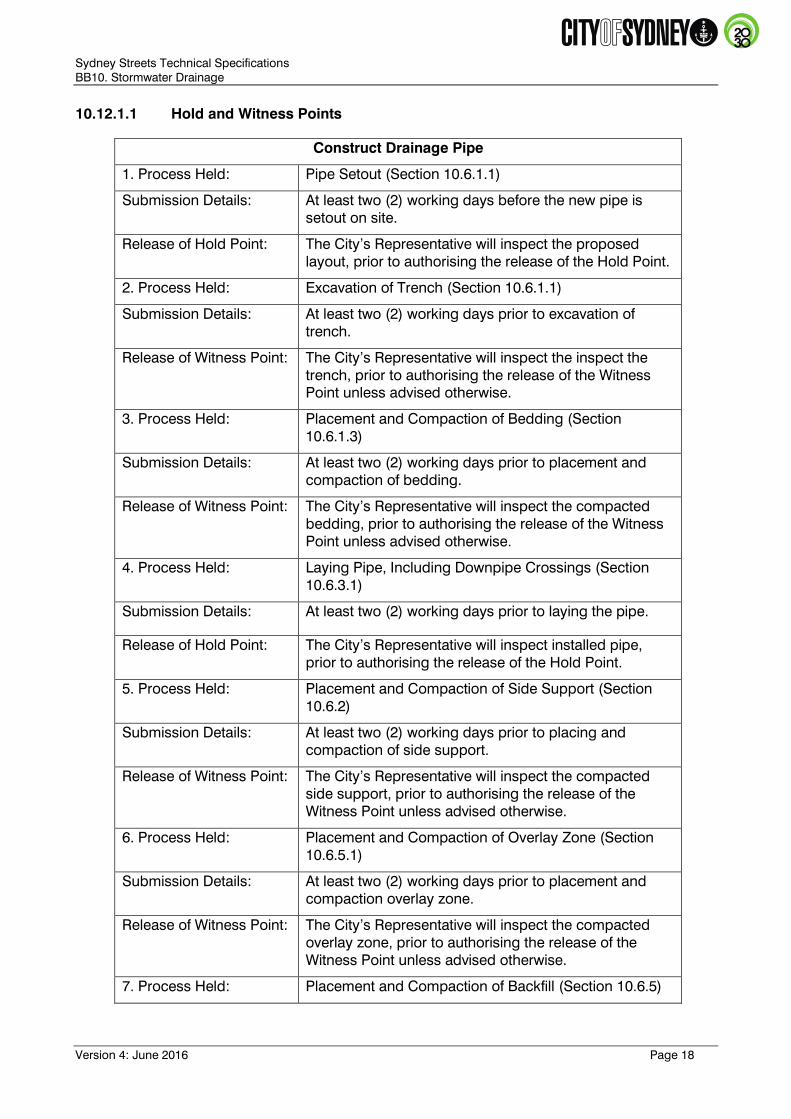
10.12.1.1 Hold and Witness Points
Construct Drainage Pipe
1. Process Held: Pipe Setout (Section 10.6.1.1)
Submission Details: At least two (2) working days before the new pipe is
setout on site.
Release of Hold Point: The City’s Representative will inspect the proposed
layout, prior to authorising the release of the Hold Point.
2. Process Held: Excavation of Trench (Section 10.6.1.1)
Submission Details: At least two (2) working days prior to excavation of
trench.
Release of Witness Point: The City’s Representative will inspect the inspect the
trench, prior to authorising the release of the Witness
Point unless advised otherwise.
3. Process Held: Placement and Compaction of Bedding (Section
10.6.1.3)
Submission Details: At least two (2) working days prior to placement and
compaction of bedding.
Release of Witness Point: The City’s Representative will inspect the compacted
bedding, prior to authorising the release of the Witness
Point unless advised otherwise.
4. Process Held: Laying Pipe, Including Downpipe Crossings (Section
10.6.3.1)
Submission Details: At least two (2) working days prior to laying the pipe.
Release of Hold Point: The City’s Representative will inspect installed pipe,
prior to authorising the release of the Hold Point.
5. Process Held: Placement and Compaction of Side Support (Section
10.6.2)
Submission Details: At least two (2) working days prior to placing and
compaction of side support.
Release of Witness Point: The City’s Representative will inspect the compacted
side support, prior to authorising the release of the
Witness Point unless advised otherwise.
6. Process Held: Placement and Compaction of Overlay Zone (Section
10.6.5.1)
Submission Details: At least two (2) working days prior to placement and
compaction overlay zone.
Release of Witness Point: The City’s Representative will inspect the compacted
overlay zone, prior to authorising the release of the
Witness Point unless advised otherwise.
7. Process Held: Placement and Compaction of Backfill (Section 10.6.5)

Sydney Streets Technical Specifications
BB10. Stormwater Drainage
Version 4: June 2016 Page 19
Submission Details: At least two (2) working days prior to placement and
compaction of backfill.
Release of Witness Point: The City’s Representative will inspect the compacted
backfill, prior to authorising the release of the Witness
Point unless advised otherwise.
Construct Precast Culvert
1. Process Held: Culvert Setout (Section 10.6.3.2)
Submission Details: At least two (2) working days before the new culvert is
setout on site.
Release of Hold Point: The City’s Representative will inspect the proposed
layout, prior to authorising the release of the Hold Point.
2. Process Held: Excavation of Trench (Section 10.6.1.1)
Submission Details: At least two (2) working days prior to excavation of
trench.
Release of Witness Point: The City’s Representative will inspect the trench, prior to
authorising the release of the Witness Point unless
advised otherwise.
3. Process Held: Placement and Compaction of Bedding (Section
10.6.1.3)
Submission Details: At least two (2) working days prior to placement and
compaction of bedding.
Release of Witness Point: The City’s Representative will inspect the compacted
bedding, prior to authorising the release of the Witness
Point unless advised otherwise.
4. Process Held: Pouring Culvert Base (Section 10.6.3.2)
Submission Details: At least two (2) working days prior to pouring culvert
base.
Release of Hold Point: The City’s Representative will inspect installed formwork
and reinforcement, prior to authorising the release of the
Hold Point.
5. Process Held: Installation of Precast Culvert (Section 10.6.3.2)
Submission Details: At least two (2) working days prior to installation of
precast culvert.
Release of Hold Point: The City’s Representative will inspect the installed
culvert, prior to authorising the release of the Hold Point.
6. Process Held: Placement and Compaction of Side Support (Section
10.6.2)
Submission Details: At least two (2) working days prior to placing and
compaction of side support.

Sydney Streets Technical Specifications
BB10. Stormwater Drainage
Version 4: June 2016 Page 20
Release of Witness Point: The City’s Representative will inspect the compacted
side support, prior to authorising the release of the
Witness Point unless advised otherwise.
7. Process Held: Placement and Compaction of Overlay Zone (Section
10.6.5.1)
Submission Details: At least two (2) working days prior to placement and
compaction overlay zone.
Release of Witness Point: The City’s Representative will inspect the compacted
overlay zone, prior to authorising the release of the
Witness Point unless advised otherwise.
8. Process Held: Placement and Compaction of Backfill (Section 10.6.5)
Submission Details: At least two (2) working days prior to placement and
compaction of backfill.
Release of Witness Point: The City’s Representative will inspect the compacted
backfill, prior to authorising the release of the Witness
Point unless advised otherwise.
Construct Cast In-Situ Culvert
1. Process Held: Culvert Setout (Section 10.6.3.2)
Submission Details: At least two (2) working days before the new culvert is
setout on site.
Release of Hold Point: The City’s Representative will inspect the proposed
layout, prior to authorising the release of the Hold Point.
2. Process Held: Excavation of Trench (Section 10.6.1.1)
Submission Details: At least two (2) working days prior to excavation of
trench.
Release of Witness Point: The City’s Representative will inspect the inspect the
trench, prior to authorising the release of the Witness
Point unless advised otherwise.
3. Process Held: Placement and Compaction of Bedding (Section
10.6.1.3)
Submission Details: At least two (2) working days prior to placement and
compaction of bedding.
Release of Witness Point: The City’s Representative will inspect the compacted
bedding, prior to authorising the release of the Witness
Point unless advised otherwise.
4. Process Held: Pouting Culvert Base (Section 10.6.3.2)

Sydney Streets Technical Specifications
BB10. Stormwater Drainage
Version 4: June 2016 Page 21
Submission Details: At least two (2) working days prior to pouring culvert
base.
Release of Hold Point: The City’s Representative will inspect installed formwork
and reinforcement, prior to authorising the release of the
Hold Point.
5. Process Held: Pouring of Cast In-situ Culvert (Section 10.6.3.2)
Submission Details: At least two (2) working days prior to pouring of cast in-
situ culvert.
Release of Hold Point: The City’s Representative will inspect formwork and
reinforcement, prior to authorising the release of the
Hold Point.
6. Process Held: Placement and Compaction of Side Support (Section
10.6.2)
Submission Details: At least two (2) working days prior to placing and
compaction of side support.
Release of Witness Point: The City’s Representative will inspect the compacted
side support, prior to authorising the release of the
Witness Point unless advised otherwise.
7. Process Held: Placement and Compaction of Overlay Zone (Section
10.6.5.1)
Submission Details: At least two (2) working days prior to placement and
compaction overlay zone.
Release of Witness Point: The City’s Representative will inspect the compacted
overlay zone, prior to authorising the release of the
Witness Point unless advised otherwise.
8. Process Held: Placement and Compaction of Backfill (Section 10.6.5)
Submission Details: At least two (2) working days prior to placement and
compaction of backfill.
Release of Witness Point: The City’s Representative will inspect the compacted
backfill, prior to authorising the release of the Witness
Point unless advised otherwise.
Construct Drainage Pit
1. Process Held: Drainage Pit Setout (Section 10.6.10)
Submission Details: At least two (2) working days before the new drainage
pit is setout on site.
Release of Hold Point: The City’s Representative will inspect the proposed
layout, prior to authorising the release of the Hold Point.
2. Process Held: Excavation for Pit (Section 10.6.10)
Submission Details: At least two (2) working days prior to excavation for pit.

Sydney Streets Technical Specifications
BB10. Stormwater Drainage
Version 4: June 2016 Page 22
Release of Witness Point: The City’s Representative will inspect the excavation,
prior to authorising the release of the Witness Point
unless advised otherwise.
3. Process Held: Placement and Compaction of Bedding (Section
10.6.1.3)
Submission Details: At least two (2) working days prior to placement and
compaction of bedding.
Release of Witness Point: The City’s Representative will inspect the compacted
bedding, prior to authorising the release of the Witness
Point unless advised otherwise.
4. Process Held: Pouring Drainage Pit (Section 10.6.10)
Submission Details: At least two (2) working days prior to pouring the
drainage pit.
Release of Hold Point: The City’s Representative will inspect installed formwork
and reinforcement, prior to authorising the release of the
Hold Point.
5. Process Held: Placement and Compaction of Backfill (Section 10.6.5)
Submission Details: At least two (2) working days prior to placement and
compaction of backfill.
Release of Witness Point: The City’s Representative will inspect the compacted
backfill, prior to authorising the release of the Witness
Point unless advised otherwise.
6. Process Held: Installation of Grate/Lid (Section 10.6.10)
Submission Details: At least two (2) working days prior to installation of
grate/lid.
Release of Hold Point: The City’s Representative will inspect the installed
grate/lid, prior to authorising the release of the Hold
Point.
7. Process Held: Installation of Lintel (Section 10.6.11)
Submission Details: At least two (2) working days prior to installation of lintel.
Release of Hold Point: The City’s Representative will inspect the installed lintel,
prior to authorising the release of the Hold Point.
Construct Raingarden
1. Process Held: Excavation for Raingarden (Section 10.7)
Submission Details: At least two (2) working days prior to excavation for
raingarden.
Release of Witness Point: The City’s Representative will inspect the excavation,
prior to authorising the release of the Witness Point
unless advised otherwise.
Sydney Streets Technical Specifications
BB10. Stormwater Drainage
Version 4: June 2016 Page 23
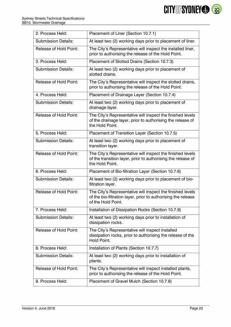
2. Process Held: Placement of Liner (Section 10.7.1)
Submission Details: At least two (2) working days prior to placement of liner.
Release of Hold Point: The City’s Representative will inspect the installed liner,
prior to authorising the release of the Hold Point.
3. Process Held: Placement of Slotted Drains (Section 10.7.3)
Submission Details: At least two (2) working days prior to placement of
slotted drains.
Release of Hold Point: The City’s Representative will inspect the slotted drains,
prior to authorising the release of the Hold Point.
4. Process Held: Placement of Drainage Layer (Section 10.7.4)
Submission Details: At least two (2) working days prior to placement of
drainage layer.
Release of Hold Point: The City’s Representative will inspect the finished levels
of the drainage layer, prior to authorising the release of
the Hold Point.
5. Process Held: Placement of Transition Layer (Section 10.7.5)
Submission Details: At least two (2) working days prior to placement of
transition layer.
Release of Hold Point: The City’s Representative will inspect the finished levels
of the transition layer, prior to authorising the release of
the Hold Point.
6. Process Held: Placement of Bio-filtration Layer (Section 10.7.6)
Submission Details: At least two (2) working days prior to placement of bio-
filtration layer.
Release of Hold Point: The City’s Representative will inspect the finished levels
of the bio-filtration layer, prior to authorising the release
of the Hold Point.
7. Process Held: Installation of Dissipation Rocks (Section 10.7.9)
Submission Details: At least two (2) working days prior to installation of
dissipation rocks.
Release of Hold Point: The City’s Representative will inspect installed
dissipation rocks, prior to authorising the release of the
Hold Point.
8. Process Held: Installation of Plants (Section 10.7.7)
Submission Details: At least two (2) working days prior to installation of
plants.
Release of Hold Point: The City’s Representative will inspect installed plants,
prior to authorising the release of the Hold Point.
9. Process Held: Placement of Gravel Mulch (Section 10.7.8)

Sydney Streets Technical Specifications
BB10. Stormwater Drainage
Version 4: June 2016 Page 24
Submission Details: At least two (2) working days prior to placement of
gravel mulch.
Release of Hold Point: The City’s Representative will inspect the finished levels
of the gravel mulch, prior to authorising the release of
the Hold Point.

Sydney Streets Technical Specifications
BB10. Stormwater Drainage
Version 4: June 2016 Page 25
10.12.2 Tolerances
The contractor shall construct the works within the following tolerances:
Item Activity Tolerances
1. Pipework
Finished horizontal position +/- 50mm from design
drawings;
Finished vertical position +/- 25mm from design
levels; and
Finished grade +/- 0.5% from design grades greater
than 3% and +/- 0.2% from design grades less than
or equal to 3%.
2. Manhole, Field Inlet,
Property Pit, I O
Structure and GPT
Finished horizontal position +/- 50mm laterally and
+/- 100mm longitudinally from the design drawings;
and
Finished vertical position +/- 25mm from both the
surface and invert design levels.
3. Inlet Gully
Finished position of an inlet gully to match the
adjacent kerb and gutter both horizontally and
vertically.