Embed Size (px)
Citation preview

B-Pump
Installation/Operating Manual

Legal information/Copyright
Installation/Operating Manual B-pump
Original operating manual
All rights reserved. The contents provided herein must neither be distributed, copied, reproduced, edited orprocessed for any other purpose, nor otherwise transmitted, published or made available to a third party withoutthe manufacturer's express written consent.
Subject to technical modification without prior notice.

Contents
1 General ..................................................................................................6
1.1 Principles ...........................................................................................................6
1.2 Installation of partly completed machinery .................................................... 6
1.3 Target group ..................................................................................................... 6
1.4 Other applicable documents ............................................................................ 6
1.5 Symbols .............................................................................................................6
2 Safety .....................................................................................................8
2.1 Key to safety symbols/markings ....................................................................... 8
2.2 General .............................................................................................................. 8
2.3 Intended use .....................................................................................................8
2.4 Personnel qualification and training ............................................................... 9
2.5 Consequences and risks caused by non-compliance with these operatinginstructions ........................................................................................................ 9
2.6 Safety awareness ..............................................................................................9
2.7 Safety information for the operator/user ..................................................... 10
2.8 Safety information for maintenance, inspection and installation work ..... 10
2.9 Unauthorised modes of operation ................................................................10
2.10 Explosion protection ...................................................................................... 10
3 Transport/Temporary Storage/Disposal .............................................12
3.1 Checking the condition upon delivery .......................................................... 12
3.2 Transport ......................................................................................................... 12
3.3 Storage/preservation ...................................................................................... 13
3.4 Return to supplier ........................................................................................... 13
3.5 Disposal ...........................................................................................................14
4 Description of the Pump (Set) ............................................................15
4.1 General description ........................................................................................ 15
4.2 Designation ..................................................................................................... 15
4.3 Name plate ...................................................................................................... 15
4.4 Design details .................................................................................................. 15
4.5 Configuration and function ........................................................................... 16
4.6 Noise characteristics .......................................................................................17
4.7 Scope of supply ............................................................................................... 17
4.8 Dimensions and weights ................................................................................17
5 Installation at Site ...............................................................................19
5.1 Safety regulations ........................................................................................... 19
5.2 Checks to be carried out prior to installation ............................................... 19
5.3 Installing the pump set .................................................................................. 20
5.4 Connecting the piping ...................................................................................22
5.5 Enclosure/insulation .......................................................................................23
Contents
B-Pump 3 of 58B-Pump

5.6 Aligning the pump and motor ...................................................................... 23
5.7 Permissible forces and moments at the pump nozzles ................................ 24
5.8 Auxiliary connections .....................................................................................25
5.9 Connection to power supply .......................................................................... 25
5.10 Checking the direction of rotation ................................................................ 26
5.11 Removing the transport lock ......................................................................... 26
5.12 Filling in lubricants .........................................................................................27
6 Commissioning/Start-up/Shutdown ...................................................28
6.1 Commissioning/start-up ................................................................................. 28
6.2 Operating limits .............................................................................................. 32
6.3 Shutdown/storage/preservation .................................................................... 35
6.4 Returning to service .......................................................................................35
7 Servicing/Maintenance .......................................................................37
7.1 Safety regulations ........................................................................................... 37
7.2 Maintenance/inspection ................................................................................. 38
7.3 Drainage/cleaning ..........................................................................................43
7.4 Dismantling the pump set .............................................................................. 43
7.5 Reassembling the pump set ........................................................................... 45
7.6 Spare parts stock ............................................................................................. 46
8 Trouble-shooting ................................................................................49
8.1 Explanation of faults ...................................................................................... 53
9 Related Documents ............................................................................54
10 EC Declaration of Conformity ............................................................55
11 Certificate of Decontamination .........................................................56
Index ....................................................................................................57
Contents
4 of 58 B-Pump

Glossary
Certificate of decontamination
A certificate of decontamination is enclosed bythe customer when returning the product tothe manufacturer to certify that the producthas been properly drained to eliminate anyenvironmental and health hazards arising fromcomponents in contact with the fluid handled.
Discharge line
The line which is connected to the dischargenozzle
Hydraulic system
The part of the pump in which the kineticenergy is converted into pressure energy
Pump
Machine without drive, additional componentsor accessories
Pump set
Complete pump set consisting of pump, drive,additional components and accessories
Suction lift line/suction head line
The line which is connected to the suctionnozzle
Glossary
5 of 58B-Pump

1 General
1.1 Principles
This operating manual is supplied as an integral part of the type series and variantsindicated on the front cover. The manual describes the proper and safe use of thisequipment in all phases of operation.
The name plate indicates the type series and size, the main operating data, the ordernumber and the order item number. The order number and order item numberuniquely identify the pump (set) and serve as identification for all further businessprocesses.
In the event of damage, immediately contact your nearest KSB service centre tomaintain the right to claim under warranty.
Noise characteristics (⇨ Section 4.6 Page 17)
1.2 Installation of partly completed machinery
To install partly completed machinery supplied by KSB, refer to the sub-sectionsunder Servicing/Maintenance.
1.3 Target group
This operating manual is aimed at the target group of trained and qualified specialisttechnical personnel. (⇨ Section 2.4 Page 9)
1.4 Other applicable documents
Table 1: Overview of other applicable documents
Document ContentsData sheet Description of the technical data of the pump (set)General arrangement drawing/outline drawing
Description of mating and installation dimensionsfor the pump (set), weights
Drawing of auxiliary connections1)
Description of auxiliary connections
Hydraulic characteristic curve Characteristic curves for the head, NPSH requiredand power input as a function of flow rate Q
General assembly drawing Sectional drawing of the pumpSub-supplier product literature1) Operating manuals and other product literature
describing accessories and integrated machinerycomponents
Spare parts lists1) Description of spare partsPiping layout1) Description of auxiliary pipingList of components Description of all pump componentsInstallation manual1) Description of the installation of other types of
installation and components
For accessories and/or integrated machinery components observe the relevantmanufacturer's product literature.
1.5 Symbols
Table 2: Symbols used in this manual
Symbol Description✓ Conditions which need to be fulfilled before proceeding with the
step-by-step instructions⊳ Safety instructions
1) If agreed to be included in the scope of supply
1 General
6 of 58 B-Pump

Symbol Description⇨ Result of an action⇨ Cross-references1.
2.
Step-by-step instructions
NoteRecommendations and important information on how to handlethe product
1 General
7 of 58B-Pump
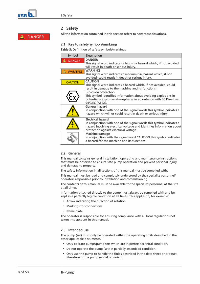
2 SafetyAll the information contained in this section refers to hazardous situations.
2.1 Key to safety symbols/markings
Table 3: Definition of safety symbols/markings
Symbol Description
! DANGER DANGERThis signal word indicates a high-risk hazard which, if not avoided,will result in death or serious injury.
! WARNING WARNINGThis signal word indicates a medium-risk hazard which, if notavoided, could result in death or serious injury.
CAUTION CAUTIONThis signal word indicates a hazard which, if not avoided, couldresult in damage to the machine and its functions.Explosion protectionThis symbol identifies information about avoiding explosions inpotentially explosive atmospheres in accordance with EC Directive94/9/EC (ATEX).General hazardIn conjunction with one of the signal words this symbol indicates ahazard which will or could result in death or serious injury.
Electrical hazardIn conjunction with one of the signal words this symbol indicates ahazard involving electrical voltage and identifies information aboutprotection against electrical voltage.Machine damage In conjunction with the signal word CAUTION this symbol indicatesa hazard for the machine and its functions.
2.2 General
This manual contains general installation, operating and maintenance instructionsthat must be observed to ensure safe pump operation and prevent personal injuryand damage to property.
The safety information in all sections of this manual must be complied with.
This manual must be read and completely understood by the specialist personnel/operators responsible prior to installation and commissioning.
The contents of this manual must be available to the specialist personnel at the siteat all times.
Information attached directly to the pump must always be complied with and bekept in a perfectly legible condition at all times. This applies to, for example:
▪ Arrow indicating the direction of rotation
▪ Markings for connections
▪ Name plate
The operator is responsible for ensuring compliance with all local regulations nottaken into account in this manual.
2.3 Intended use
The pump (set) must only be operated within the operating limits described in theother applicable documents.
▪ Only operate pumps/pump sets which are in perfect technical condition.
▪ Do not operate the pump (set) in partially assembled condition.
▪ Only use the pump to handle the fluids described in the data sheet or productliterature of the pump model or variant.
! DANGER
2 Safety
8 of 58 B-Pump

▪ Never operate the pump without the fluid to be handled.
▪ Observe the minimum flow rates indicated in the data sheet or product literature(to prevent overheating, bearing damage, etc.).
▪ Observe the maximum flow rates indicated in the data sheet or productliterature (to prevent overheating, mechanical seal damage, cavitation damage,bearing damage, etc.).
▪ Do not throttle the flow rate on the suction side of the pump (to preventcavitation and bearing damage).
▪ Observe the minimum water levels as specified in the product literature.
▪ Consult the manufacturer about any use or mode of operation not described inthe data sheet or product literature.
Prevention of foreseeable misuse
▪ Never open discharge-side shut-off elements further than permitted.
– The maximum flow rate specified in the data sheet or product literaturewould be exceeded.
– Risk of cavitation damage
▪ Never exceed the permissible operating limits specified in the data sheet orproduct literature regarding pressure, temperature, etc.
▪ Observe all safety information and instructions in this manual.
2.4 Personnel qualification and training
All personnel involved must be fully qualified to transport, install, operate, maintainand inspect the machinery this manual refers to.
The responsibilities, competence and supervision of all personnel involved intransport, installation, operation, maintenance and inspection must be clearlydefined by the operator.
Deficits in knowledge must be rectified by means of training and instructionprovided by sufficiently trained specialist personnel. If required, the operator cancommission the manufacturer/supplier to train the personnel.
Training on the pump (set) must always be supervised by technical specialistpersonnel.
2.5 Consequences and risks caused by non-compliance with these operatinginstructions
▪ Non-compliance with these operating instructions will lead to forfeiture ofwarranty cover and of any and all rights to claims for damages.
▪ Non-compliance can, for example, have the following consequences:
– Hazards to persons due to electrical, thermal, mechanical and chemicaleffects and explosions
– Failure of important product functions
– Failure of prescribed maintenance and servicing practices
– Hazard to the environment due to leakage of hazardous substances
2.6 Safety awareness
In addition to the safety information contained in this manual and the intended use,the following safety regulations shall be complied with:
▪ Accident prevention, health and safety regulations
▪ Explosion protection regulations
▪ Safety regulations for handling hazardous substances
▪ Applicable standards and laws
2 Safety
9 of 58B-Pump
2.7 Safety information for the operator/user
▪ The operator shall fit contact guards for hot, cold and moving parts and checkthat the guards function properly.
▪ Do not remove any contact guards while the pump is running. The onlyexception is the guard of the packing chamber.
▪ Provide the personnel with protective equipment and make sure it is used.
▪ Contain leakages (e.g. at the shaft seal) of hazardous fluids handled (e.g.explosive, toxic, hot) so as to avoid any danger to persons and the environment.Adhere to all relevant laws.
▪ Eliminate all electrical hazards. (In this respect refer to the applicable nationalsafety regulations and/or regulations issued by the local energy supplycompanies.)
▪ Provided that switching off the pump does not increase potential risk, fit anemergency-stop control device in the immediate vicinity of the pump (set) duringpump set installation.
2.8 Safety information for maintenance, inspection and installation work
▪ Modifications or alterations of the pump are only permitted with themanufacturer's prior consent.
▪ Use only original spare parts or parts authorised by the manufacturer. The use ofother parts can invalidate any liability of the manufacturer for resulting damage.
▪ The operator ensures that all maintenance, inspection and installation work isperformed by authorised, qualified specialist personnel who are thoroughlyfamiliar with the manual.
▪ Only carry out work on the pump (set) during standstill of the pump.
▪ The pump casing must have cooled down to ambient temperature.
▪ Pump pressure must have been released and the pump must have been drained.
▪ When taking the pump set out of service always adhere to the proceduredescribed in the manual. (⇨ Section 6.3 Page 35)
▪ Decontaminate pumps which handle fluids posing a health hazard. (⇨ Section 7.3Page 43)
▪ As soon as the work has been completed, re-install and/or re-activate any safety-relevant and protective devices. Before returning the product to service, observeall instructions on commissioning. (⇨ Section 6.1 Page 28)
2.9 Unauthorised modes of operation
Never operate the pump (set) outside the limits stated in the data sheet and in thismanual.
The warranty relating to the operating reliability and safety of the supplied pump(set) is only valid if the equipment is used in accordance with its intended use.
2.10 Explosion protection
Always observe the information on explosion protection given in this section whenoperating the pump (set) in potentially explosive atmospheres.
Only pumps/pump sets marked as explosion-proof and identified as such in the datasheet may be used in potentially explosive atmospheres.
Special conditions apply to the operation of explosion-proof pump sets to ECDirective 94/9/EC (ATEX). The explosion-proof status of the pump set is only assured if the pump set is used inaccordance with its intended use. Never operate the pump set outside the limits stated in the data sheet and on thename plate.
! DANGER
2 Safety
10 of 58 B-Pump

Prevent impermissible modes of operation at all times. For information on application options of individual components (if any) inpotentially explosive atmospheres, refer to the manufacturer's product literature.
2.10.1 Repair
Special regulations apply to repair work on explosion-proof pumps. Modifications oralteration of the pump set could affect explosion protection and are only permittedafter consultation with the manufacturer.
Repair work at the flameproof joints must only be performed in accordance with themanufacturer's instructions. Repair to the values in tables 1 and 2 of EN 60079-1 isnot permitted.
2 Safety
11 of 58B-Pump
3 Transport/Temporary Storage/Disposal
3.1 Checking the condition upon delivery
1. On transfer of goods, check each packaging unit for damage.
2. In the event of in-transit damage, assess the exact damage, document it andnotify KSB or the supplying dealer (as applicable) and the insurer about thedamage in writing immediately.
3.2 Transport
DANGER
Lifting lugs of pump/motor overloadedDanger to life from falling parts!
▷ Never transport the pump set components (pump/motor) in any way other thanthose illustrated in the section on transport options.
▷ Refer to the weights of the individual components stated in the manufacturer'sproduct literature.
DANGER
The pump or individual components could slip out of the suspension arrangementDanger to life from falling parts!
▷ Always transport the pump or components in the specified position.
▷ Never attach the suspension arrangement to free shaft areas on the pump.
▷ Refer to the weights indicated for the individual components.
▷ Comply with the applicable health and safety regulations.
▷ Use suitable, permitted lifting accessories.
DANGER
Improper transportRisk of injury from lifting heavy components!
▷ Select lifting accessories which are suitable for the component weight.
▷ Always use the attachment points provided for the lifting accessories.
▷ Comply with the applicable health and safety regulations.
WARNINGPump set tipping over or rolling offRisk of personal injury!
▷ Always secure vertically positioned pump sets against tipping over.
▷ Always secure horizontally positioned pump sets against rolling off.
1. Refer to the weights of the individual components stated in the generalarrangement drawing and/or the manufacturer's product literature.
2. Select suitable lifting equipment.
3. Transport the pump/pump set and individual components as illustrated.2)
2) See other applicable documents for transport options
3 Transport/Temporary Storage/Disposal
12 of 58 B-Pump

2. Always flush and clean the pump, particularly if it has been used for handlingnoxious, explosive, hot or other hazardous fluids.
3. If the pump set has handled fluids whose residues could lead to corrosion in thepresence of atmospheric humidity or could ignite upon contact with oxygen,the pump set must also be neutralised, and anhydrous inert gas must be blownthrough the pump to ensure drying.
4. Always complete and enclose a certificate of decontamination when returningthe pump (set).Always indicate any safety and decontamination measures taken. (⇨ Section 11Page 56)
NOTEIf required, a blank certificate of decontamination can be downloaded from theKSB web site at: www.ksb.com/certificate_of_decontamination
3.5 Disposal
WARNINGFluids, consumables and supplies which are hot or pose a health hazardHazard to persons and the environment!
▷ Collect and properly dispose of flushing fluid and any residues of the fluidhandled.
▷ Wear safety clothing and a protective mask, if required.
▷ Observe all legal regulations on the disposal of fluids posing a health hazard.
1. Dismantle the pump (set).Collect greases and other lubricants during dismantling.
2. Separate and sort the pump materials, e.g. by:- Metals- Plastics- Electronic waste- Greases and other lubricants
3. Dispose of materials in accordance with local regulations or in anothercontrolled manner.
3 Transport/Temporary Storage/Disposal
14 of 58 B-Pump

4 Description of the Pump (Set)
4.1 General description
▪ Deep-well turbine pump with mixed flow impeller.
▪ Electric motor or combustion engine.
▪ Discharge nozzle arranged above or below floor and variant for dry installation.
▪ Application: non-corrosive fluids, industry, water supply, fire-fighting systems,general industry, pressure boosting, irrigation,…
▪ Single-stage or multistage hydraulic system
Pump for use in water works, irrigation and drainage pumping systems, powerstations and industrial water supply.
4.2 DesignationExample: B 16 B/2 VN / V1
Table 4: Key to the designation
Code DescriptionB Type series16 Well diameter in inches (16 = 16")B Hydraulic system (B impeller)2 Number of stages of the hydraulic systemVN Type of installation (VN = Discharge nozzle above floor3))V1 Type of drive (V1 = direct drive by vertical electric motor3))
4.3 Name plate
DWT
P-No. 9971312132 / 000100Q 400 m3/hn 1450 1/min
KSB Pumps Co. Ltd.
Mat.-No. ZN 3804 - H52x74
2013
H 43 m
B 16 B/2 VN / V1
2
5
4
3
8
7
61
Fig. 1: Name plate (example)
1 Pump type 2 Designation of the pump set3 Order number 4 Flow rate5 Speed 6 Year of supply7 Order item number 8 Head
4.4 Design detailsDesign
▪ Centrifugal pump
3) Refer to the general arrangement drawing/outline drawing
4 Description of the Pump (Set)
15 of 58B-Pump

▪ Vertical installation
▪ Single-stage or multi-stage
▪ Nominal diameter of the discharge nozzles: 80 mm to 500 mm
▪ Hole diameter: 6" to 24"
Pump casing
▪ Radially split relative to the shaft
▪ Suction/discharge casing, 1 or more pump bowls
▪ Replaceable casing wear rings
Impeller4)
▪ Single-entry mixed flow impeller, hydraulically unbalanced
▪ Optionally with impeller wear rings
▪ Axially locked in position on the shaft via locking and stage sleeves
Pump, intermediate and top shafts4)
▪ Connected via threaded, conical or split muff coupling
▪ Torque transmission from pump shaft to impeller/coupling(s) via locking sleeve(s)or key(s)
Shaft seal4)
▪ Gland packing
▪ Mechanical seal
▪ With or without shaft protecting sleeve
Shaft guide bearing
▪ Medium-lubricated plain bearings
▪ Pump shaft supported by bearing bush in each pump bowl(B series: additional support by bearing bushes in suction/discharge casing)
▪ Intermediate shaft supported by bearing spiders in bearing bushes installedbetween column pipes
▪ Shaft protecting sleeves (stage sleeves)from size B14 in pump bowl and in all column pipe bearings
Thrust and radial bearing4)
▪ Grease-packed rolling element bearings
▪ Angular contact ball bearings in back-to-back arrangement
▪ Uncooled
Direction of rotation
The pump's direction of rotation is anti-clockwise, seen from the top shaft of thepump.
4.5 Configuration and function
See general assembly drawing5)
Configuration
4) See other applicable documents for delivered design5) See other applicable documents for delivered design
4 Description of the Pump (Set)
16 of 58 B-Pump

Pump and motor are connected by a coupling depending on the variant (see otherapplicable documents).The stage casings, column pipes and distributor casings are centred via flangeconnections and bolted together.If necessary, a suction strainer with or without foot valve may be installed upstreamof the pump to protect the pump against coarse particles and foreign objects.
The fluid enters the suction casing via a suction strainer (if any) and flows to thesuction impeller (connected to the rotating shaft) at a given pressure. In the impeller,the kinetic energy is imparted to the fluid handled and converted to pressure.The fluid flows from the impeller to the pump bowl where its pressure is furtherincreased via further partial conversion of the kinetic energy. This procedure is repeated from one stage to the next with the effect that thepressure increases at each stage by the same amount, i.e. by the discharge pressureper stage.After the last pump bowl, the fluid flows through the discharge casing into thecolumn pipe.The clearance gap at the casing wear ring prevents any fluid from flowing back fromthe stage casing into the suction area of the previous impeller.The pump discharge pressure creates an axial force at the rotor of single-stage andmultistage centrifugal pumps, which is absorbed by the thrust bearing in the motorstool together with the weight of the complete pump rotor and the radial forces.The thrust and radial bearing also positions the rotor axially.
The pump is sealed by a shaft seal (mechanical seal or gland packing).
4.6 Noise characteristics
Surface sound pressure level LpA6): see data sheet for values.
4.7 Scope of supply
Depending on the model, the following items are included in the scope of supply:
▪ Pump
▪ Drive
▪ Base frame, supporting frame, foundation blocks, foundation rails, foundationring
▪ Coupling, coupling guard
▪ Cardan shaft, guard
▪ Fasteners for pump and base frame
▪ Optional accessories:
– Vibration monitoring
– Temperature monitoring device (PT 100)
– Constant level oiler
– Pressure gauge
– Measuring nipple for shock pulse measurement
– Cyclone
4.8 Dimensions and weights
▪ For pump dimensions and weights, please refer to the pump data sheet.
▪ For motor dimensions and weights, please refer to the motor documentation.
Design
Function
Sealing
6) Spatial average; as per ISO 3744 and EN 12639; valid for pump operation in the Q/Qopt = 0.80 - 1.1 range and for non-cavitating operation. If noise levels are to be warranted, add an allowance of +3 dB for measuring and manufacturingtolerances.
4 Description of the Pump (Set)
17 of 58B-Pump

5 Installation at Site
5.1 Safety regulations
For all work involving assembly, reassembly and installation, observe the followingsafety information:
DANGER
Improper installation in potentially explosive atmospheresExplosion hazard!Damage to the pump set!
▷ Comply with the applicable local explosion protection regulations.
▷ Observe the information in the data sheet and on the name plates of pump andmotor.
DANGER
Improper transportRisk of injury from lifting heavy components!
▷ Select lifting accessories which are suitable for the component weight.
▷ Always use the attachment points provided for the lifting accessories.
▷ Comply with the applicable health and safety regulations.
DANGER
Pump in a vertical position tipping overDanger to life from pump or components tipping over!
▷ Attach the components to be installed to the hoisting tackle and keep themsecured until the screwed connections have been fastened.
▷ Always install the pump (set) in the sequence described.
▷ Always place components in their centre of gravity position on a suitablesurface to prevent them from tipping over.
5.2 Checks to be carried out prior to installationPlace of installation
WARNINGInstallation on mounting surfaces which are unsecured and cannot support the loadPersonal injury and damage to property!
▷ Observe the required compressive strength class C25/30 of the concrete inexposure class XC1 to EN 206-1.
▷ The mounting surface must have set and must be completely horizontal andeven.
▷ Observe the weights indicated.
1. Check the structural requirements. All structural work required must have been prepared in accordance with thedimensions stated in the outline drawing/general arrangement drawing.
5 Installation at Site
19 of 58B-Pump

Suction head/suction lift line
WARNINGForeign objects in the intake/suction linePersonal injury and damage to property!
▷ Make sure that the intake area (e.g.: intake chamber/intake channel) is cleanand free from foreign objects.
▷ Make sure that the suction line is clean and free from foreign objects.
▷ Protect intake area leading into any existing suction line against ingress offoreign matter.
▷ Any existing suction-side flow distribution equipment must be installed firmlyand securely.
1. Check suction-side conditions. No foreign objects must enter the pump.
2. Clean the intake or suction line as necessary.
3. Install suction strainer if required.
5.3 Installing the pump set
NOTESee other applicable documents for the type of installation of the delivered design.
NOTESee other applicable documents for other types of installation than thosedocumented here.
Depending on the type of installation, relevant instructions need to be carried out asapplicable:
▪ Prepare and install the base frame/supporting frame/foundation blocks/foundation rails/foundation ring.
▪ Install the pump and motor on the prepared base frame/supporting frame/foundation blocks/foundation rails/foundation ring.
▪ Check the alignment of pump and motor.
▪ Align the pump with the piping.
▪ Install and align the coupling.
▪ Connect the piping.
▪ Perform precision alignment of pump and motor, if possible with larger motors.
▪ Remove any transport locks.
Installation on existing elements
DANGER
The pump or individual components could slip out of the suspension arrangementDanger to life from falling parts!
▷ Always transport the pump or components in the specified position.
▷ Never attach the suspension arrangement to free shaft areas on the pump.
▷ Refer to the weights and centre of gravity indicated for the individualcomponents.
▷ Observe the applicable local health and safety regulations.
▷ Use suitable, permitted lifting accessories.
5 Installation at Site
20 of 58 B-Pump

DANGER
Incorrect assemblyRisk of injury from lifting heavy components and placing them upright
▷ Only transport and place the pump and individual components upright in thespecified position.
▷ Select a suitable lifting accessory according to the weight of the componentand the installation requirements.
▷ Always use the attachment points provided for the lifting accessories.
✓ The relevant general arrangement drawing is available.
✓ The foundation has the required strength and characteristics for the loadsindicated in the general arrangement drawing.
✓ The foundation complies with the dimensions given in the general arrangementdrawing.
1. Transport and place the pump (set) upright in accordance with the otherapplicable documents.
2. Lower the pump onto the foundation elements provided.
3. Align the pump with the piping and connect it to the foundation.
4. Mount the motor and motor stool as described in the motor manufacturer'soperating instructions.
5. Align the coupling as described in the coupling manufacturer's operatingmanual.
5.3.1 Checking and adjusting the pump rotor clearance
CAUTIONIncorrect pump rotor adjustmentDamage to the pump/pump set components
▷ Establish the permissible clearance by axially raising the pump rotor as per thevalue specified for the axial clearance in the general assembly drawing. (⇨Section 9 Page 54)
NOTEThe rotor must be checked and re-adjusted after the first installation or followingcomplete dismantling!Check and re-adjustment are always carried out before the motor and the couplingplate are fitted!
✓ Suitably dimensioned lifting equipment and lifting accessories are available.
✓ The pump has been completely assembled.
✓ The motor has not been mounted.
✓ The hexagon nuts for fine-adjustment of the gland have been loosened.
✓ The pump rotor rests with the blades inside the wear ring.
1. The pump rotor position is set with the pump in an upright position.
2. Establish the permissible clearance by raising the pump rotor in axial direction.
3. Measure the distance from the contact face of the motor stool to the end of thetop shaft and record the measured value.
4. Raise the pump rotor carefully by turning the adjusting nut clockwise until thepump rotor has reached the value specified for the axial clearance in thegeneral assembly drawing.
5. After raising the rotor by the value specified for the axial clearance, turn theadjusting nut further until the holes of the locking screws align with the nextthreaded holes. Note: This causes the permissible clearance to increase slightlyin size.
5 Installation at Site
21 of 58B-Pump

6. Mount the locking screws of the adjusting nut.
7. Try turning the pump rotor by hand to see if it seizes up.
5.4 Connecting the piping
DANGER
Impermissible loads acting on the pump nozzlesDanger to life from leakage of hot, toxic, corrosive or flammable fluids!
▷ Do not use the pump as an anchorage point for the piping.
▷ The pipelines have been anchored in close proximity to the pump andconnected without transmitting any stresses or strains.
▷ Observe permissible forces and moments at the pump nozzles.
▷ Take appropriate measures to compensate thermal expansion of the piping.
CAUTIONIncorrect earthing during welding work at the pipingDestruction of rolling element bearings (pitting effect)!
▷ Never earth the electric welding equipment on the pump or baseplate.
▷ Prevent current flowing through the rolling element bearings.
NOTEIt is recommended to install check and shut-off elements in the system, dependingon the type of plant and pump. However, such elements must not obstruct properdrainage or hinder disassembly of the pump.
✓ The suction lift line has been laid with a rising slope, the suction head line with adownward slope towards the pump.
✓ A flow stabilisation section having a length equivalent to at least twice thediameter of the suction flange has been provided upstream of the suction flange.
✓ The nominal diameters of the pipelines are equal to or greater than the nominaldiameters of the pump nozzles. A hydraulically optimised elbow is providedbetween the suction lift line/suction head line and the pump.
✓ To prevent excessive pressure losses, adapters to larger diameters have a diffuserangle of approx. 8°.
✓ The pipelines have been anchored in close proximity to the pump and connectedwithout transmitting any stresses or strains.
1. Thoroughly clean, flush and blow through all vessels, pipelines and connections(especially of new installations).
2. Before installing the pump in the piping, remove the flange covers on thesuction and discharge nozzles of the pump.
Fig. 2: Connection with expansion joints
3. If the owner/operator supplies an expansion joint, it has to be braced withexternal tie rods to prevent impermissible reaction forces.It is impermissible to connect the pump with unbraced expansion joints.
5 Installation at Site
22 of 58 B-Pump

CAUTIONWelding beads, scale and other impurities in the pipingDamage to the pump!
▷ Remove any impurities from the piping.
▷ If necessary, install a filter/strainer.
4. If required, install a filter/strainer in the piping.
5. Connect the pump nozzles to the piping.
CAUTIONAggressive flushing and pickling agentsDamage to the pump!
▷ Match the cleaning operation mode and duration for flushing and picklingservice to the casing and seal materials used.
5.5 Enclosure/insulation
WARNINGFailure to re-install or re-activate protective devicesRisk of injury from moving parts or escaping fluid!
▷ As soon as the work is completed, re-install and/or re-activate any safety-relevant and protective devices.
WARNINGDistributor casing and bearing housing take on the same temperature as the fluidhandled.Risk of burns!
▷ Insulate the distributor casing.
▷ Fit protective equipment.
CAUTIONHeat build-up in the bearing housingDamage to the bearing!
▷ Never insulate the bearing housing and bearing cover.
5.6 Aligning the pump and motor
DANGER
Inadmissible temperatures at the coupling or bearings due to misalignment of thecouplingExplosion hazard!Risk of burns!
▷ Make sure that the coupling is correctly aligned at all times.
CAUTIONMisalignment of pump and motor shaftsDamage to pump, motor and coupling!
▷ Always check the coupling after the pump has been installed and connected tothe piping.
5 Installation at Site
23 of 58B-Pump

B
AA
B
1 1
2
Fig. 3: Checking the coupling alignment
1 Straight-edge 2 Gauge
✓ The coupling guard and footboard, if any, have been removed.
1. Place the straight-edge axially on both coupling halves.
2. Leave the straight-edge in this position and turn the coupling by hand. The coupling is aligned correctly if the distances A) and B) to the respectiveshafts are the same at all points around the circumference.The radial and axial deviation between the two coupling halves must notexceed 0.05 mm. Observe the coupling manufacturer's operating manual!
3. In case of misalignment, loosen the bolts on the motor and re-align.
4. Re-tighten the bolts.
5. Check coupling and shaft for proper functioning. Check that coupling/shaft canbe rotated by hand.
6. Re-install the coupling guard and footboard, if any.
7. Check the distance between coupling and coupling guard. The coupling guardmust not touch the coupling.
5.7 Permissible forces and moments at the pump nozzles
Fig. 4: Permissible forces and moments
See the general arrangement drawing for forces and moments at the pump nozzles.The values indicated do not apply to reaction forces from unbraced expansion joints!(See the general arrangement drawing for permissible values, or contact KSB)
The resulting permissible forces have been determined according to
The data on forces and moments apply to static piping loads only. If the limits areexceeded, they must be checked and verified.If a computerised strength analysis is required, please contact KSB. The values are only applicable if the pump is installed on completely groutedelements and bolted to a rigid and level foundation.
5 Installation at Site
24 of 58 B-Pump
5.8 Auxiliary connections
WARNINGScrew plugs subjected to pressureRisk of injuries by parts flying off and escaping fluid!
▷ Never use screw plugs for releasing pressure from the pump casing.
▷ Always use suitable venting devices (e.g. vent valve).
WARNINGFailure to use or incorrect use of auxiliary connections (e.g. barrier fluid, flushingliquid, etc.)Risk of injury from escaping fluid!Risk of burns!Malfunction of the pump!
▷ Refer to the general arrangement drawing, the piping layout and pumpmarkings (if any) for the quantity, dimensions and locations of auxiliaryconnections.
▷ Use the auxiliary connections provided.
See the general arrangement drawing for auxiliary connections
5.9 Connection to power supply
DANGER
Incorrect electrical installationExplosion hazard!
▷ For electrical installation, also observe the requirements of IEC 60079-14.
▷ Always connect explosion-proof motors via a motor protection switch.
DANGER
Work on the pump set by unqualified personnelDanger of death from electric shock!
▷ Always have the electrical connections installed by a trained and qualifiedelectrician.
▷ Observe IEC 60364 (DIN VDE 0100) regulations and, for explosion-proof pumpsets, IEC 60079 (DIN VDE 0165).
▷ Observe the motor manufacturer's operating instructions.
WARNINGUnintentional starting of pump setRisk of injury by moving parts!
▷ Make sure that the pump set cannot be started up unintentionally.
▷ Always make sure the electrical connections are disconnected before carryingout work on the pump set.
WARNINGIncorrect connection to the mainsDamage to the mains network, short circuit!
▷ Observe the technical specifications of the local energy supply companies.
1. Check the available mains voltage against the data on the motor name plate.
2. Select an appropriate start-up method.
5 Installation at Site
25 of 58B-Pump

NOTEA motor protection device is recommended.
5.9.1 Earthing
DANGER
Electrostatic chargingExplosion hazard!Fire hazard!Damage to the pump set!
▷ Connect the PE conductor to the earthing terminal provided.
5.10 Checking the direction of rotation
DANGER
Temperature increase resulting from contact between rotating and stationarycomponentsExplosion hazard!Damage to the pump set!
▷ Never check the direction of rotation by starting up the unfilled pump set.
▷ Separate the pump from the motor to check the direction of rotation.
DANGER
Rotating shaft during direction of rotation checkRisk of injury!
▷ Maintain a safe distance to the pump set.
▷ Comply with the general health and safety regulations.
CAUTIONDrive and pump running in the wrong direction of rotationDamage to the pump!
▷ Refer to the arrow indicating the direction of rotation on the pump.
▷ Check the direction of rotation. If required, check the electrical connection andcorrect the direction of rotation.
✓ The pump has been completely separated from the motor.
✓ All components at the motor (e.g. coupling half at the motor shaft) have beensecured.
1. Start the motor and stop it again immediately to determine the motor'sdirection of rotation.
2. Check the direction of rotation. The motor's direction of rotation must match the arrow indicating the directionof rotation on the pump.
3. If the motor runs in the wrong direction of rotation, check the electricalconnection of the motor and the control system, if applicable.
5.11 Removing the transport lock
Remove the transport lock, if any.
5 Installation at Site
26 of 58 B-Pump

5.12 Filling in lubricants
CAUTIONTemporary storage of the pump set too longContamination, condensation, resinification or leakage of the grease!
▷ Check for contamination and condensation.
▷ Change the complete grease fill before returning the pump set to service.
▷ Replace the grease fill every time the bearings are dismantled.
Grease-lubricated bearings have been packed with grease at the factory.
Fill the bearing housings with lubricant up to the mark.Oil quality: see data sheetOil quantity: see data sheet
CAUTIONInsufficient quantity of lubricant in bearing housingDamage to the bearings!
▷ Check the lubricant level regularly.
▷ Always fill the bearing housing up to the mark.
NOTEAn excessively high oil level or grease quantity can lead to a temperature rise andto leakage of the fluid handled or oil.
Grease-lubricatedbearings
Oil-lubricatedbearings
5 Installation at Site
27 of 58B-Pump

6 Commissioning/Start-up/Shutdown
6.1 Commissioning/start-up
6.1.1 Prerequisites for commissioning/start-up
Before commissioning/starting up the pump set, make sure that the followingconditions are met:
▪ The pump set has been properly connected to the electric power supply and isequipped with all protection devices. (⇨ Section 5.9 Page 25)
▪ The pump has been flooded up to the specified minimum water level. (Seegeneral arrangement drawing)
▪ The direction of rotation has been checked. (⇨ Section 5.10 Page 26)▪ All auxiliary connections required are connected and operational.
▪ The transport lock has been removed.
▪ The lubricants have been checked and filled in.
▪ After prolonged shutdown of the pump (set), the required activities have beencarried out. (⇨ Section 6.4 Page 35)
▪ The coupling alignment has been checked.
6.1.2 Priming and venting the pump
DANGER
Risk of potentially explosive atmosphere inside the pumpExplosion hazard!
▷ Before starting up the pump, vent the suction line and the pump and primethem with the fluid to be handled.
DANGER
Shaft seal failure caused by dry runningHot fluid may escape!
▷ Before start-up, flood the pump and the suction line, if any, up to the minimumwater level specified.
1. Close all drains and drain lines.
2. Flood the pump and the suction line, if any, up to the minimum water levelspecified.For suction lift operation, evacuate the pump.
3. Fully open the shut-off element in the suction line.
4. If the discharge line is equipped with a check valve, the shut-off element in thedischarge line may remain open as long as there is some back pressure. If this isnot the case, the shut-off element in the discharge line must be closed.
5. Fully open all auxiliary connections (barrier fluid, flushing fluid etc.).If liquid is supplied from an external source, make sure the data indicated in thedata sheet (pressure, flow rate, etc.) is observed.
6. Open the venting element/ensure proper venting.
⇨ The shut-off element in the discharge line opens as flow starts (e.g. swing checkvalve) or is opened immediately before pump start-up (e.g. gate valve alreadyslightly open when pump is started).
6 Commissioning/Start-up/Shutdown
28 of 58 B-Pump

6.1.3 Start-up
DANGER
Non-compliance with the permissible pressure and temperature limits if the pump isoperated with the suction and/or discharge line closed.Explosion hazard!Leakage of hot or toxic fluids!
▷ Never operate the pump with the shut-off elements in the suction line and/ordischarge line closed.
▷ Only start up the pump set with the discharge-side shut-off element slightly orfully open.
DANGER
Excessive temperatures due to dry running or excessive gas content in the fluidhandledExplosion hazard!Damage to the pump set!
▷ Never operate the pump set without liquid fill.
▷ Prime the pump as specified.
▷ Always operate the pump within the permissible operating range.
WARNINGPump set with high noise levelsDamage to hearing!
▷ Persons must only enter the vicinity of the running pump set if they are wearingprotective clothing/ear protection.
▷ See noise characteristics. (⇨ Section 4.6 Page 17)
CAUTIONAbnormal noises, vibrations, temperatures or leakageDamage to the pump!
▷ Switch off the pump (set) immediately.
▷ Eliminate the causes before returning the pump set to service.
✓ Intake area (e.g. intake chamber) and system piping have been cleaned.
✓ Pump, suction line and inlet tank, if any, have been vented and primed with thefluid to be handled.
✓ The lines for priming and venting have been closed.
CAUTIONStart-up against open discharge lineMotor overload!
▷ Make sure the motor has sufficient power reserves.
1. Fully open the shut-off element in the suction head/suction lift line.
2. Close or slightly open the shut-off element in the discharge line.
3. Start up the motor.
4. Immediately after the pump has reached full rotational speed, slowly open theshut-off element in the discharge line and adjust it to comply with the dutypoint.
6 Commissioning/Start-up/Shutdown
29 of 58B-Pump

DANGER
Seal leakages at operating temperatureHot or toxic fluid could escape!
▷ After the operating temperature has been reached and/or in the event ofleakage, switch off the pump set and tighten the bolts on the casing to thespecified torques.
▷ If there is leakage at the shaft seal, check the coupling alignment and re-align ifnecessary.
6.1.4 Checking the shaft seal
The mechanical seal only leaks slightly or invisibly (as vapour) during operation.Mechanical seals are maintenance-free.
The gland packing must drip slightly during operation.
(approx. 20 drops per minute)
DANGER
The temperatures at the gland packing have risen above the permissible limitsExplosion hazard!
▷ Gland packings are not approved for use in potentially explosive atmospheres.
▷ Immediately switch off the pump set!
The minimum leakage required depends on the fluid handled, pressure, slidingvelocity and temperature.
See data sheet for the leakage rates at the gland packing.
CAUTIONExcessive leakage or no leakage at the gland packingDamage to the pump!
▷ Excessive leakage: Re-tighten the gland follower until the required leakage rateis reached.
▷ No leakage: Switch off the pump set immediately.
WARNINGWork in the immediate vicinity of rotating partsRisk of hand injuries!
▷ Always have this work performed by trained personnel.
▷ Take particular caution when performing this work.
Adjusting the leakage
1. Only lightly tighten the nuts of the gland follower by hand.
2. Use a feeler gauge to verify that the gland follower is mounted centred and ata right angle to the shaft.
⇨ The gland must leak after the pump has been primed.(Only applies to pumps with suction lift line and the respective excess inletpressure.)
The leakage can be reduced.
1. Tighten the nuts of the gland follower by 1/6 turn.
2. Monitor the leakage for another five minutes.
Excessive leakage:Repeat steps 1 and 2 until the minimum value has been reached.
Mechanical seal
Gland packing
Prior to commissioning
After five minutesof operation
6 Commissioning/Start-up/Shutdown
30 of 58 B-Pump

Not enough leakage:Slightly loosen the nuts at the gland follower.
No leakage:Switch off the pump set immediately!Loosen the gland follower and repeat start-up.
Checking for leakage
After the leakage has been adjusted, monitor the leakage for about two hours atmaximum fluid temperature. Check that enough leakage occurs at the gland seal at minimum fluid pressure.
6.1.5 Shutdown
CAUTIONReverse flow of fluid handled (not applicable to pumps with reverse rotation lock)Motor or winding damage!Excessive reverse runaway speed of the motor!
▷ Thrust bearing damage following prolonged periods of reverse rotation.(Applies to the radial bearing of the oil-lubricated plain bearing design)
▷ Observe the permissible reverse runaway speed of the motor. See themanufacturer's product literature included with the supplied documentation.
▷ Close the shut-off elements.
✓ The shut-off element in the suction line is and remains open.
1. Close the shut-off element in the discharge line slowly.
2. Switch off the motor immediately after closing the shut-off element and makesure the pump set runs down smoothly to a standstill.
NOTEIf the discharge line is equipped with a non-return or check valve, the shut-offelement in the discharge line may remain open, provided the site's requirementsand regulations are taken into account and observed.
NOTEIf shut-off is not possible, the pump will run in reverse direction.The reverse runaway speed must be lower than the rated speed.
For prolonged shutdown periods:
1. Close the shut-off element in the suction line, if any.
2. Close the auxiliary connections.
CAUTIONRisk of freezing during prolonged pump shutdown periodsDamage to the pump!
▷ Drain the pump and the cooling/heating chambers (if any) or otherwise protectthem against freezing.
6 Commissioning/Start-up/Shutdown
31 of 58B-Pump

6.2 Operating limits
DANGER
Non-compliance with operating limits for pressure, temperature, fluid handled andspeedExplosion hazard!Hot or toxic fluid could escape!
▷ Comply with the operating data indicated in the data sheet.
▷ Never use the pump for handling fluids it is not designed for.
▷ Avoid prolonged operation against a closed shut-off element.
▷ Never operate the pump at temperatures, pressures or rotational speedsexceeding those specified in the data sheet or on the name plate unless thewritten consent of the manufacturer has been obtained.
6.2.1 Maximum operating pressure
CAUTIONPermissible operating pressure exceededDamage to connections and seals!
▷ Never exceed the operating pressure specified in the data sheet.
The maximum operating pressure depends on the pump size, pump material andnominal pressure of the flange design. Neither the material / size dependent maximum pressure nor the maximum nominalpressure of the flange must be exceeded.
Maximum operating pressure: see data sheet.
6.2.2 Temperature of the fluid handled
CAUTIONFluid temperature too high or too lowDamage to the pump!
▷ Avoid prolonged operation against a closed shut-off element.
▷ Never operate the pump at temperatures above or below those specified in thedata sheet or on the name plate unless the written consent of the manufacturerhas been obtained.
If the values are not indicated in the data sheet, the following temperature limitsapply. The temperatures must neither be below nor above these limits.
Table 5: Temperature limits of the fluid handled
Minimum fluid temperature 0 °CMaximum fluid temperature + 60 °C
6.2.3 Abrasive fluids/solids
CAUTIONAbrasive particles or solids in the fluidDamage to the pump!
▷ Observe the limits specified indicated in the data sheet.
▷ Flush the piping prior to commissioning.
▷ Install a filter in the system, if required.
6 Commissioning/Start-up/Shutdown
32 of 58 B-Pump

Do not exceed the maximum permissible solids content specified in the data sheet.When the pump handles fluids containing abrasive substances, increased wear of thehydraulic system and the shaft seal are to be expected. In this case, reduce theintervals commonly recommended for servicing and maintenance.
NOTESolids, especially long fibres, plastic residues or similar solids can lead to clogging ofthe barrier or flushing lines and to mechanical seal damage.
6.2.4 Hydraulic operating range
CAUTIONNon-compliance with hydraulic operating limitsDamage to the pump and motor
▷ Observe the limits in the data sheet.
▷ Brief passage through the critical range below Qmin is permissible during start-up.
General information on the hydraulic operating range
NPSHRequired
NPSHAvailable
Qmin
Q
H
Qmax
Q-Hcurve
B
A A
C
System curve
Fig. 5: Pump operating range
NPSH
Available
Inlet pressure available inthe system
NPSH
Required
Required inlet pressure
A Operating limit B Operating pointC Operating range without
NPSH safety allowance
The flow rate Q will develop automatically as a function of the discharge head H, inline with the pump's characteristic curve. The pump's permissible operating range haslimits that are independent of each other in terms of their cause.
Low flow operating limit This limit is indicated in the H/Q characteristic by Qmin or by discontinuation of thecharacteristic curve in the diagram.
NPSH-related limits under off-design conditionsThe low flow and overload limits are determined by the ratio of NPSHRequired toNPSHAvailable.
6 Commissioning/Start-up/Shutdown
33 of 58B-Pump

The NPSH limits are determined as follows: The intersections of NPSHRequired and NPSHAvailable are projected onto the H/Qcharacteristic, where they represent the operating limits.
If the pump set is operated outside its operating limits or system-related changesoccur, check the NPSH values. If necessary, consult your nearest customer service centre.
6.2.5 Frequency of starts
DANGER
Excessive surface temperature of the motorExplosion hazard!Damage to the motor!
▷ In case of explosion-proof motors, observe the frequency of starts specified inthe manufacturer's product literature.
CAUTIONRe-starting while motor is still running downDamage to the pump (set)!
▷ Do not re-start the pump set before the pump rotor has come to a standstill.
The frequency of starts is usually determined by the maximum temperature increaseof the motor. This largely depends on the power reserves of the motor in steady-state operation and on the starting conditions (DOL, star-delta, moments of inertia,etc). Observe the motor manufacturer's operating instructions.
6.2.6 Fluid handled
6.2.6.1 Temperature of the fluid handled
CAUTIONFluid temperature too high or too lowDamage to the pump!
▷ Avoid prolonged operation against a closed shut-off element.
▷ Never operate the pump at temperatures above or below those specified in thedata sheet or on the name plate unless the written consent of the manufacturerhas been obtained.
If the values are not indicated in the data sheet, the following temperature limitsapply. The temperatures must neither be below nor above these limits.
Table 6: Temperature limits of the fluid handled
Minimum fluid temperature 0 °CMaximum fluid temperature + 60 °C
6.2.6.2 Abrasive fluids/solids
CAUTIONAbrasive particles or solids in the fluidDamage to the pump!
▷ Observe the limits specified indicated in the data sheet.
▷ Flush the piping prior to commissioning.
▷ Install a filter in the system, if required.
6 Commissioning/Start-up/Shutdown
34 of 58 B-Pump

Do not exceed the maximum permissible solids content specified in the data sheet.When the pump handles fluids containing abrasive substances, increased wear of thehydraulic system and the shaft seal are to be expected. In this case, reduce theintervals commonly recommended for servicing and maintenance.
NOTESolids, especially long fibres, plastic residues or similar solids can lead to clogging ofthe barrier or flushing lines and to mechanical seal damage.
6.3 Shutdown/storage/preservation
6.3.1 Measures to be taken for shutdown
The pump (set) remains installed
✓ Sufficient fluid is supplied for the functional check run of the pump.7)
1. For prolonged shutdown periods, start up the pump (set) regularly betweenonce a month and once every three months for approximately five minutes. This will prevent the formation of deposits within the pump and the pumpintake area.7)
The pump (set) is removed from the pipe and stored
✓ The pump has been properly drained and the safety instructions for dismantlingthe pump have been observed.
1. Spray-coat the inside wall of the pump casing, and in particular the impellerclearance areas, with a preservative.
2. Spray the preservative through the suction and discharge nozzles.It is advisable to then close the pump nozzles (e.g. with plastic caps or similar).
3. Oil or grease all exposed machined parts and surfaces of the pump (withsilicone-free oil and grease, food-approved if required) to protect them againstcorrosion.
4. Contact KSB regarding preservation of the bearing.
5. Remove the gland packing.
If the pump set is to be stored temporarily, only preserve the wetted componentsmade of low-alloy materials. Commercially available preservatives can be used forthis purpose. Observe the manufacturer's instructions for application/removal.
Observe any additional instructions and information provided
6.4 Returning to service
For returning the pump to service observe the sections on commissioning/start-up(⇨ Section 6.1 Page 28) and the operating limits (⇨ Section 6.2 Page 32) .In addition, carry out all servicing/maintenance operations before returning thepump (set) to service. (⇨ Section 7 Page 37)
WARNINGFailure to re-install or re-activate protective devicesRisk of personal injury from moving parts or escaping fluid!
▷ As soon as the work is complete, re-install and/or re-activate any safety-relevantand protective devices.
7) If the intake area (e.g. intake elbow) and the pump have been drained, special measures must be taken for the functionalcheck run. See section on routine maintenance and inspection intervals or contact KSB.
6 Commissioning/Start-up/Shutdown
35 of 58B-Pump

7 Servicing/Maintenance
7.1 Safety regulations
DANGER
Improperly serviced pump setExplosion hazard!Damage to the pump set!
▷ Service the pump set regularly.
▷ Prepare a maintenance schedule with special emphasis on lubricants, shaft sealand coupling.
The operator ensures that all maintenance, inspection and installation work isperformed by authorised, qualified specialist personnel who are thoroughly familiarwith the manual.
WARNINGUnintentional starting of pump setRisk of injury by moving parts!
▷ Make sure that the pump set cannot be started up unintentionally.
▷ Always make sure the electrical connections are disconnected before carryingout work on the pump set.
WARNINGFluids and supplies posing a health hazard and/or hot fluids or suppliesRisk of injury!
▷ Observe all relevant laws.
▷ When draining the fluid take appropriate measures to protect persons and theenvironment.
▷ Decontaminate pumps which handle fluids posing a health hazard.
WARNINGInsufficient stabilityRisk of crushing hands and feet!
▷ During assembly/dismantling, secure the pump (set)/pump parts to preventtipping or falling over.
A regular maintenance schedule will help avoid expensive repairs and contribute totrouble-free, reliable operation of the pump (set)and pump components with aminimum of maintenance expenditure and work.
NOTEAll maintenance, service and installation work can be carried out by KSB Service.See data sheet for contact addresses
Never use force when dismantling and reassembling the pump set.
7 Servicing/Maintenance
B / BU 37 of 58B-Pump

7 Servicing/Maintenance
7.1 Safety regulations
DANGER
Improperly serviced pump setExplosion hazard!Damage to the pump set!
▷ Service the pump set regularly.
▷ Prepare a maintenance schedule with special emphasis on lubricants, shaft sealand coupling.
The operator ensures that all maintenance, inspection and installation work isperformed by authorised, qualified specialist personnel who are thoroughly familiarwith the manual.
WARNINGUnintentional starting of pump setRisk of injury by moving parts!
▷ Make sure that the pump set cannot be started up unintentionally.
▷ Always make sure the electrical connections are disconnected before carryingout work on the pump set.
WARNINGFluids and supplies posing a health hazard and/or hot fluids or suppliesRisk of injury!
▷ Observe all relevant laws.
▷ When draining the fluid take appropriate measures to protect persons and theenvironment.
▷ Decontaminate pumps which handle fluids posing a health hazard.
WARNINGInsufficient stabilityRisk of crushing hands and feet!
▷ During assembly/dismantling, secure the pump (set)/pump parts to preventtipping or falling over.
A regular maintenance schedule will help avoid expensive repairs and contribute totrouble-free, reliable operation of the pump (set)and pump components with aminimum of maintenance expenditure and work.
NOTEAll maintenance, service and installation work can be carried out by KSB Service.See data sheet for contact addresses
Never use force when dismantling and reassembling the pump set.
7 Servicing/Maintenance
37 of 58B-Pump

7.2 Maintenance/inspection
7.2.1 Supervision of operation
DANGER
Risk of potentially explosive atmosphere inside the pumpExplosion hazard!
▷ The pump internals in contact with the fluid to be handled, including the sealchamber and auxiliary systems must be filled with the fluid to be handled at alltimes.
▷ Provide sufficient inlet pressure.
▷ Provide an appropriate monitoring system.
DANGER
Excessive temperatures as a result of bearings running hot or defective bearing sealsExplosion hazard!Fire hazard!Damage to the pump set!
▷ Regularly check the lubricant level.
▷ Regularly check the temperatures of the rolling element bearings/bearinghousing.
▷ Regularly check the rolling element bearings for running noises.
DANGER
Excessive temperatures due to dry-runningExplosion hazard!Fire hazard!Damage to the pump set!
▷ Never operate the pump set without liquid fill.
▷ Never close the shut-off element in the suction line and/or supply line duringpump operation.
CAUTIONImpermissibly high temperature of fluid handledDamage to the pump!
▷ Prolonged operation against a closed shut-off element is not permitted(heating up of the fluid).
▷ Observe the temperature limits in the data sheet and in the section onoperating limits. (⇨ Section 6.2 Page 32)
While the pump is in operation, observe and check the following:
▪ The pump must run quietly and free from vibrations at all times.
▪ In case of oil lubrication, ensure the oil level is correct. (⇨ Section 5.12 Page 27)▪ Check the shaft seal. (⇨ Section 6.1.4 Page 30)▪ Check the static seals for leakage.
▪ Check the rolling element bearings for running noises.Vibrations, noise and an increase in current input occurring during unchangedoperating conditions indicate wear.
▪ Monitor the correct functioning of any auxiliary connections.
▪ Monitor the stand-by pump.To make sure that the stand-by pumps are ready for operation, start them uponce a month.
7 Servicing/Maintenance
38 of 58 B-Pump

▪ Monitor the bearing temperature.The bearing temperature must not exceed the value specified in the data sheet(measured on the outside of the bearing housing).If temperature monitoring is provided, the bearing temperatures indicated in thedata sheet apply to the measuring points of the sensors.
▪ Check the flexible or torsion-resistant elements of the coupling/Cardan shaft andreplace as necessary.
▪ Check any pressure gauges.
▪ Check the drive as described in the manufacturer's product literature.
▪ Check that the fitted coupling guard does not touch the coupling.
▪ Make sure that the earth connection is fitted and marked.
▪ Cooling system (if any)Take the pump out of service at least once a year to thoroughly clean the coolingsystem.
CAUTIONOperation outside the permissible bearing temperatureDamage to the pump!
▷ The bearing temperature of the pump (set) must never exceed the valuespecified in the data sheet (measured on the outside of the bearing housing).
NOTEAfter commissioning, increased temperatures may occur at grease-lubricated rollingelement bearings due to the running-in process. The final bearing temperature isonly reached after a certain period of operation (up to 48 hours depending on theconditions).
7.2.2 Inspection work
DANGER
Excessive temperatures caused by friction, impact or frictional sparksExplosion hazard!Fire hazard!Damage to the pump set!
▷ Regularly check the coupling guard, plastic components and other guards ofrotating parts for deformation and sufficient distance from rotating parts.
7.2.2.1 General information
Check and service all components of the pump set as described in the correspondingoperating manuals provided by the manufacturers.The manufacturer's product literature is included with the order documents whichare supplied with the delivery.
7.2.2.2 Routine maintenance and inspection intervals
Table 7: Routine maintenance and inspection intervals
Interval Number ofpersons
Time Maintenance job
Daily 1 6 min. ▪ Check shaft seal leakage.1 6 min. ▪ Check the oil level and top up
the oil, if required (only for oil-lubricated bearings)
7 Servicing/Maintenance
39 of 58B-Pump

Interval Number ofpersons
Time Maintenance job
Weekly 1 15 min. ▪ Check pump operation (inlet pressure, head, bearingtemperature, noise andvibrations).
Monthly 1 15 min. ▪ Check torsional play/condition ofthe coupling/Cardan shaft (seeoperating manual for thecoupling/Cardan shaft).
1 15 min. ▪ Switch to a stand-by pump, ifany, or carry out a functionalcheck run (5 minutes).
8) 1 15 min. ▪ Re-lubricate grease-packedrolling element bearings, re-lubrication quantity see datasheet
8) 1 15 min. ▪ Check oil-lubricated rollingelement bearings
Every 4 years or ifdischarge head drops
2 9) ▪ Generally inspect and overhaulthe pump in accordance with theoperating instructions.
▪ Check and replace, if necessary:
– Bearings, casing wear ring,impeller wear ring, shaftprotecting sleeve
– Impeller and shaft
– Fit new seals and gaskets.
7.2.2.3 Checking the clearances
Excessive clearances will affect pump performance. Losses in efficiency and dischargehead will occur.
To check the clearance gaps, remove the rotor. If the clearance gap is larger thanpermitted, replace the casing wear ring and impeller wear ring (if any).
See data sheet for clearances.
NOTEIf the max. clearance gaps specified are exceeded, replace the components affected.
7.2.2.4 Cleaning filters
CAUTIONInsufficient inlet pressure due to clogged filter/strainer in the suction lineDamage to the pump!
▷ Monitor contamination of filter/strainer with suitable means (e.g. differentialpressure gauge).
▷ Clean filter/strainer at appropriate intervals.
8) See data sheet for intervals9) Depending on work required due to operating hours, operating conditions etc.
7 Servicing/Maintenance
40 of 58 B-Pump

7.2.2.5 Lubrication and lubricant change of thrust bearings
DANGER
Excessive temperatures as a result of bearings running hot or defective bearing sealsExplosion hazard!Fire hazard!Damage to the pump set!
▷ Regularly check the bearing seals.
▷ Regularly check the condition of the lubricant.
▷ Regularly check the oil level and top up the oil (oil-lubricated bearings only).
CAUTIONTemporary storage of the pump set too longDeposits, condensation, resinification or leakage of grease!
▷ Change the complete grease fill before returning the pump set to service.
▷ Replace the grease fill every time the bearings are dismantled.
CAUTIONPump stored too long or incorrectlyDamage to the pump!
▷ Check especially the rolling element bearings and the lubricant. If any damageis suspected, replace the rolling element bearings.
7.2.2.5.1 Grease lubrication
The bearings are supplied packed with high-quality grease.
7.2.2.5.1.1 Re-lubricating with grease
WARNINGWork in the immediate vicinity of rotating partsRisk of hand injuries!
▷ Always have this work performed by trained personnel.
▷ Take particular caution when performing this work.
CAUTIONContaminated lubricating nipplesContamination of the lubricating grease!
▷ Clean the grease lubricating nipples before re-lubricating them.
1. Clean the lubricating nipples, if contaminated.
2. Position the grease press on the lubricating nipple.
3. Press in the grease.
7.2.2.5.1.2 Changing the grease
✓ The bearing assembly must be dismantled to change the grease.
1. Thoroughly clean bearing, bearing housing and bearing cover with petrol,benzene or a similar cleaning agent. Carefully remove the cleaning agent fromthe components again.
2. Check that all parts are in perfect working order. Replace any damaged parts.
3. Completely fill the cavities between the rolling elements of the bearings withgrease.
7 Servicing/Maintenance
41 of 58B-Pump

4. Fill the cavities in the bearing cover with grease until they are about half full.
7.2.2.5.1.3 Intervals
▪ Re-lubricating with grease: see data sheet for intervals, at least every 2 years
▪ Changing the grease: every time the pump is dismantled
7.2.2.5.1.4 Grease quality
▪ Grease quality: see data sheet
7.2.2.5.1.5 Grease quantity
▪ Quantities for lubrication and re-lubrication: see data sheet
7.2.2.5.2 Oil lubrication
The rolling element bearings are usually lubricated with mineral oil.
7.2.2.5.2.1 Topping up/changing the lubricant
CAUTIONInsufficient quantity of lubricant in bearing housingDamage to the bearings!
▷ Check the lubricant level regularly.
▷ Fill the bearing housing up to the mark.
NOTEAn excessively high oil level or grease quantity can lead to a temperature rise andto leakage of the fluid handled or oil.
Oil is usually topped up during standstill of the pump. If it is unavoidable to top upthe constant level-oiler with the pump running, temporary oil leakage may occur.Provide an appropriate drip collector.
WARNINGLubricants posing a health hazard and/or hot lubricantsHazard to persons and the environment!
▷ When draining the lubricant take appropriate measures to protect persons andthe environment.
▷ Wear safety clothing and a protective mask, if required.
▷ Collect and dispose of any lubricants.
▷ Observe all legal regulations on the disposal of fluids posing a health hazard.
✓ A suitable container for the used oil is on hand.
1. Place the container beneath the lubricant draining element.
2. Unscrew/open the lubricant draining element and drain the lubricant.
3. Once the bearing housing has run empty, close the lubricant drain.
4. Remove the venting element.
5. Fill the lubricant up to the mark using the opening provided for the ventingelement.
6. After a short time, check whether the oil level has dropped at the marking. Ifthe oil level is too low, top it up with oil.
7 Servicing/Maintenance
42 of 58 B-Pump

7.2.2.5.2.2 Intervals
▪ Oil change interval: see data sheet
7.2.2.5.2.3 Oil quality
▪ Oil quality: see data sheet
7.2.2.5.2.4 Oil quantity
▪ Oil quantity: see data sheet
7.3 Drainage/cleaning
WARNINGFluids, consumables and supplies which are hot or pose a health hazardHazard to persons and the environment!
▷ Collect and properly dispose of flushing fluid and any residues of the fluidhandled.
▷ Wear safety clothing and a protective mask, if required.
▷ Observe all legal regulations on the disposal of fluids posing a health hazard.
If the fluids handled by the pump (set) leave residues which might lead to corrosiondamage when coming into contact with atmospheric humidity, or which might ignitewhen coming into contact with oxygen, the pump (set) must be flushed through,neutralised, and anhydrous inert gas must be blown through the pump for dryingpurposes.
If available, use the suction-side connections to drain the fluid handled (see generalarrangement drawing/outline drawing).
7.4 Dismantling the pump set
7.4.1 General information/Safety regulations
DANGER
Insufficient preparation of work on the pump (set)Risk of injury!
▷ Properly shut down the pump set.
▷ Close the shut-off elements in suction and discharge line.
▷ Drain the pump and release the pump pressure.
▷ Close any auxiliary connections.
▷ Allow the pump set to cool down to ambient temperature.
WARNINGUnqualified personnel performing work on the pump (set)Risk of injury!
▷ Always have repair and maintenance work performed by specially trained,qualified personnel.
WARNINGImproper lifting/moving of heavy assemblies or componentsPersonal injury and damage to property!
▷ Use suitable transport devices, lifting equipment and lifting tackle to moveheavy assemblies or components.
7 Servicing/Maintenance
43 of 58B-Pump

WARNINGUnintentional starting of pump setRisk of injury by moving parts!
▷ Make sure that the pump set cannot be started up unintentionally.
▷ Always make sure the electrical connections are disconnected before carryingout work on the pump set.
WARNINGHot surfaceRisk of injury!
▷ Allow the pump set to cool down to ambient temperature.
WARNINGComponents with sharp edgesRisk of cutting or shearing injuries!
▷ Always use appropriate caution for installation and dismantling work.
▷ Wear work gloves.
Observe the general safety instructions and information. (⇨ Section 2.8 Page 10)For any work on the motor, observe the instructions of the relevant motormanufacturer.
For dismantling and reassembly refer to the general assembly drawing.
In the event of damage you can always contact our service staff.
7.4.2 Preparing the pump set
DANGER
The pump or individual components could slip out of the suspension arrangementDanger to life from falling parts!
▷ Always transport the pump or components in the specified position.
▷ Never attach the suspension arrangement to the free shaft end of the pump.
▷ Refer to the weight of the individual components and the centre of gravity.
▷ Observe the applicable local accident prevention regulations.
▷ Use suitable, permitted lifting accessories, e.g. self-tightening lifting tongs.
DANGER
Pump (set) tipping overDanger to life from pump or components tipping over!
▷ Never undo screwed connections without suspending and securing thecomponents to be dismantled in a hoisting tackle.
▷ Only dismantle the pump (set) in the specified order.
▷ Only deposit components on suitable surfaces and in centre-of-gravity position,so that they cannot tip over.
NOTEVertical installationFor dismantling a vertically installed pump, the complete pump has to be removedand placed in horizontal position. Then, the complete rotor can be removed anddismantled.
7 Servicing/Maintenance
44 of 58 B-Pump

Preparing for dismantling
✓ The gate valves in the suction and discharge lines have been closed.
✓ The motor has been disconnected from the power supply and secured againstunintentional start-up.
✓ The pump has been drained.
1. Remove the flushing line and any auxiliary feed lines connected to the pump.
2. Remove coupling guard 681 and guard plates 680.
3. Separate the pump-end coupling half as described in the operating instructionsfor the coupling. (See the manufacturer's product literature included with thesupplied documentation.)
7.4.3 Dismantling the supplied design/installation
NOTESee other applicable documents for removing and dismantling the delivered design/installation.
7.5 Reassembling the pump set
7.5.1 General information/Safety regulations
DANGER
The pump or individual components could slip out of the suspension arrangementDanger to life from falling parts!
▷ Always transport the pump or components in the specified position.
▷ Never attach the suspension arrangement to the free shaft end of the pump.
▷ Refer to the weight of the individual components and the centre of gravity.
▷ Observe the applicable local accident prevention regulations.
▷ Use suitable, permitted lifting accessories, e.g. self-tightening lifting tongs.
DANGER
Pump (set) tipping overDanger to life from pump or components tipping over!
▷ Never undo screwed connections without suspending and securing thecomponents to be dismantled in a hoisting tackle.
▷ Only dismantle the pump (set) in the specified order.
▷ Only deposit components on suitable surfaces and in centre-of-gravity position,so that they cannot tip over.
WARNINGImproper lifting/moving of heavy assemblies or componentsPersonal injury and damage to property!
▷ Use suitable transport devices, lifting equipment and lifting tackle to moveheavy assemblies or components.
WARNINGUnqualified personnel performing work on the pump (set)Risk of injury!
▷ Always have repair and maintenance work performed by specially trained,qualified personnel.
7 Servicing/Maintenance
45 of 58B-Pump

WARNINGUnintentional starting of pump setRisk of injury by moving parts!
▷ Make sure that the pump set cannot be started up unintentionally.
▷ Always make sure the electrical connections are disconnected before carryingout work on the pump set.
CAUTIONImproper reassemblyDamage to the pump!
▷ Reassemble the pump (set) in accordance with the general rules of soundengineering practice.
▷ Replace any damaged/worn parts.
▷ Use original spare parts only.
WARNINGComponents heated up for installationRisk of burns to hands!
▷ Wear protective gloves suitable for installation work.
▷ Let components cool down after installation.
Observe the general safety instructions and information. (⇨ Section 2.8 Page 10)For any work on the motor, observe the instructions of the relevant motormanufacturer.
For dismantling and reassembly refer to the general assembly drawing.
In case of damage you can always contact our service staff.
Always reassemble the pump in accordance with the corresponding general assemblydrawing and installation instructions.
▪ Never use O-rings that have been glued together from material sold by themetre.
▪ Replace all O-rings and V-rings and clean their locating fits on the shaft. Fit allsealing elements on the relevant components before starting with the assembly.
▪ Observe the installation instructions regarding cleaning, lubricating and sealingagents.
▪ Remove any residues of liquid sealants before starting with the assembly.
For reassembly, tighten all screws and bolts as specified in this manual.
7.5.2 Assembling the supplied design/installation
NOTESee other applicable documents for installing and assembling the delivered design/installation.
7.6 Spare parts stock
7.6.1 Ordering spare parts
Please order any replacement or spare parts required from:
Sequence
O-rings/V-rings
Assembly adhesives
Tightening torques
7 Servicing/Maintenance
46 of 58 B-Pump

KSB Pumps Company Limited
16/2, Sir Aga Khan RoadLahore, Pakistan
Telefax: +92 42 3636 8878-4 Telephone: +92 42 3630 4173-4
Always quote the following data when ordering replacement or spare parts:
▪ Type series
▪ Size
▪ KSB order number
▪ Year of construction
Refer to the name plate for all data.
Also specify the following data:
▪ Description
▪ Part No.
▪ Quantity of spare parts
▪ Shipping address
▪ Mode of dispatch (freight, mail, express freight, air freight)
Refer to the general assembly drawing/list of components for part numbers anddescriptions.
7.6.2 Recommended spare parts stock for 2 years' operation to DIN 24296
Table 8: Quantity of spare parts for recommended spare parts stock
Part No. Description Number of pumps (including stand-by pumps)
2 3 4 5 6 / 7 8 / 9 10and
more
Quantity of spare parts211 Pump shaft10)11) 1 1 1 2 2 2 20 %212 Intermediate shaft10)12) 1*n12) 1*n12) 1*n12) 2*n12) 2*n12) 2*n12) 20 %213 Top shaft10) 1 1 1 2 2 2 20 %230 Impeller11) 1*n12) 1*n12) 1*n12) 2*n12) 2*n12) 2*n12) 20 %231 Suction stage impeller12)11) 1 1 1 2 2 2 20 % Rotor11) (for multistage pumps) 1 1 1 2 2 2 20 %320 Angular contact ball bearing 1 1 1 2 2 3 25 %321 Deep-groove ball bearing12) 1 1 1 2 2 3 25 %382.1 Bearing carrier13) 1 1 1 2 2 4 50 %384 Thrust collar13) 1 1 1 2 2 4 50 %400.1-x Gasket 4*n12) 6*n12) 8*n12) 8*n12) 9*n12) 12*n12) 150 %411.1 x . Joint ring 4*n12) 6*n12) 8*n12) 8*n12) 9*n12) 12*n12) 150 %412.1-x O-ring 4*n12) 6*n12) 8*n12) 8*n12) 9*n12) 12*n12) 150 %422.1-x Felt ring 4*n12) 6*n12) 8*n12) 8*n12) 9*n12) 10*n12) 100 %433 Mechanical seal Mechanical seal,
complete11)1 1 2 2 2 3 25 %
Primary ring11) 2 3 4 5 6 7 90 %Mating ring11) 2 3 4 5 6 7 90 %O-rings11) 2 3 4 5 7 9 100 %Secondary seal atmating ring11)
2 3 4 5 7 9 100 %
10) With keys, shaft bolts/screws and shaft nuts11) Optional12) If any13) If the thrust and radial bearing is a plain bearing
7 Servicing/Maintenance
47 of 58B-Pump

Part No. Description Number of pumps (including stand-by pumps)
2 3 4 5 6 / 7 8 / 9 10and
more
Quantity of spare partsSet of springs11) 1 1 1 1 2 2 20 %
461 Gland packing (set)14) 4 4 6 6 6 8 100 %502 Casing wear ring 2*n 2*n 2*n 3*n 3*n 4*n 50 %503 Impeller wear ring12) 2*n 2*n 2*n 3*n 3*n 4*n 50 %521 Stage sleeve12)15) 2*n 2*n 2*n 3*n 3*n 4*n 50 %524.1-x Shaft protecting sleeve
(shaft seal)12)2 2 2 3 3 4 50 %
526/920.x Centring sleeve/locknut15) 1 1 1 2 2 2 20 %529 Bearing sleeve
(shaft protecting sleeve)2 3 4 5 7 9 100 %
540 Bush (thrust and radial bearing)13) 1 1 2 2 3 4 50 %541 Interstage bush12)15) 2*n 3*n 4*n 5*n 7*n 9*n 100 %52-1 Locking sleeve, complete12)15) 1*n 1*n 1*n 2*n 2*n 2*n 20 %544 Threaded bush15) 2 3 4 5 7 9 545.1-x Bearing bush 2*n 3*n 4*n 5*n 7*n 9*n 100 %840 Torque-
transmitting coupling elements1 1 2 2 3 4 30 %
851/852 Conical/threaded coupling 1*n 1*n 2*n 2*n 3*n 4*n 30 %920.1 Nut with two flats12)15) 1 1 2 2 3 4 30 %931.1 x . Lockwasher12)15) 1 1 2 2 3 4 30 %
14) Supplied by the metre15) Not considered in DIN 24296
7 Servicing/Maintenance
48 of 58 B-Pump

8 Trouble-shooting
WARNINGImproper remedial work on the pump (set)Risk of injury!
▷ For any work performed in order to remedy faults on the pump (set) observethe relevant information given in this operating manual or the productliterature provided by the accessories manufacturers.
Pump pressure is too low
Excessive pump discharge pressure
Excessive flow rate
Pump delivers insufficient flow rate
Excessive power consumption
Pump is running but does not deliver
Pump stops during operation
Vibrations and noise during pump operation
Impermissible rise of temperature inside the pump
Excessive bearing temperature
Excessive leakage at the shaft seal
Motor is overloaded
Leakage at the pump
Table 9: Trouble-shooting
A B C D E F G H I J K L M Possible cause Remedy16)
✘ ✘ ✘ ✘ ✘ ✘ ✘ ✘ ✘ ✘ ✘ Operating point B does not matchthe Q and H performance datacalculated in advance.
▪ Re-adjust to duty point(e.g. close/open shut-offelement accordingly).
✘ ✘ ✘ Pump or piping are not completelyvented.
▪ Vent pump.
✘ ✘ ✘ ✘ ✘ ✘ Inlet line or impeller clogged ▪ Clean the impeller.
▪ Check system for impurities.
▪ Remove deposits in pumpand/or piping.
▪ Check any strainers installed/suction opening.
✘ ✘ ✘ ✘ ✘ Formation of air pockets in thepiping
▪ Fit venting device.
▪ Alter piping layout.✘ ✘ ✘ ✘ ✘ NSPH available/water level too
low.▪ Check operating mode.
▪ Increase back pressure bythrottling.
▪ Correct suction conditions.
▪ Increase suction head.
▪ Install pump at a lower level.
▪ Fully open the shut-offelement in the inlet line, ifany.
▪ Alter the inlet line if pipinglosses are too high, if any.
A
B
C
D
E
F
G
H
I
J
K
L
M
16) Pump pressure must be released before attempting to remedy faults on parts which are subjected to pressure.
8 Trouble-shooting
49 of 58B-Pump

8 Trouble-shooting
WARNINGImproper remedial work on the pump (set)Risk of injury!
▷ For any work performed in order to remedy faults on the pump (set) observethe relevant information given in this operating manual or the productliterature provided by the accessories manufacturers.
Pump pressure is too low
Excessive pump discharge pressure
Excessive flow rate
Pump delivers insufficient flow rate
Excessive power consumption
Pump is running but does not deliver
Pump stops during operation
Vibrations and noise during pump operation
Impermissible rise of temperature inside the pump
Excessive bearing temperature
Excessive leakage at the shaft seal
Motor is overloaded
Leakage at the pump
Table 9: Trouble-shooting
A B C D E F G H I J K L M Possible cause Remedy16)
✘ ✘ ✘ ✘ ✘ ✘ ✘ ✘ ✘ ✘ ✘ Operating point B does not matchthe Q and H performance datacalculated in advance.
▪ Re-adjust to duty point(e.g. close/open shut-offelement accordingly).
✘ ✘ ✘ Pump or piping are not completelyvented.
▪ Vent pump.
✘ ✘ ✘ ✘ ✘ ✘ Inlet line or impeller clogged ▪ Clean the impeller.
▪ Check system for impurities.
▪ Remove deposits in pumpand/or piping.
▪ Check any strainers installed/suction opening.
✘ ✘ ✘ ✘ ✘ Formation of air pockets in thepiping
▪ Fit venting device.
▪ Alter piping layout.✘ ✘ ✘ ✘ ✘ NSPH available/water level too
low.▪ Check operating mode.
▪ Increase back pressure bythrottling.
▪ Correct suction conditions.
▪ Increase suction head.
▪ Install pump at a lower level.
▪ Fully open the shut-offelement in the inlet line, ifany.
▪ Alter the inlet line if pipinglosses are too high, if any.
A
B
C
D
E
F
G
H
I
J
K
L
M
16) Pump pressure must be released before attempting to remedy faults on parts which are subjected to pressure.
8 Trouble-shooting
49 of 58B-Pump

A B C D E F G H I J K L M Possible cause Remedy16)
✘ Shaft seal worn/Score marks orroughness on shaft protectingsleeve.
▪ Check flushing liquid/barrierfluid pressure.
▪ Clean barrier fluid, supplyexternal barrier fluid, ifnecessary, or increase barrierfluid pressure.
▪ Fit new shaft seal.
▪ Replace worn components bynew ones.
▪ Replace shaft protectingsleeve.
✘ ✘ ✘ ✘ Unfavourable flow to pumpsuction nozzle
▪ Check the inflow conditions ofthe intake reservoir and intakechamber.
▪ Check whether pipe routingresults in swirling or irregularflow (e.g. downstream ofelbow) and correct, ifnecessary.
✘ ✘ ✘ Gland follower, seal coverexcessively tightened or tightenedaskew, incorrect packing material.
▪ Correct.
▪ Replace.
▪ Correct.
▪ Replace gland packing.
▪ Replace worn components bynew ones.
✘ ✘ ✘ Lack of cooling liquid or dirtycooling chamber.
▪ Check flushing liquid/barrierfluid pressure.
▪ Clean barrier fluid, supplyexternal barrier fluid, ifnecessary, or increase barrierfluid pressure.
▪ Increase cooling liquidquantity.
▪ Clean coolant/coolingchamber.
✘ ✘ Pump is warped or sympatheticvibrations in the piping.
▪ Re-align pump/drive.
▪ Check piping connections andsecure fixing of pump; improvefixing of piping, if necessary.
▪ Fix pipelines using anti-vibration material.
✘ Increased axial thrust ▪ Check duty point/pumpselection.
▪ Check operating mode.
▪ Check suction side flowconditions.
✘ ✘ Insufficient or excessive quantity oflubricant or unsuitable lubricant
▪ Clean the bearings.
▪ Top up, reduce or changelubricant.
✘ Non-compliance with specifiedcoupling distance
▪ Correct distance in accordancewith the general arrangementdrawing.
16) Pump pressure must be released before attempting to remedy faults on parts which are subjected to pressure.
8 Trouble-shooting
51 of 58B-Pump

A B C D E F G H I J K L M Possible cause Remedy16)
✘ ✘ ✘ ✘ Motor is running on 2 phases only. ▪ Replace defective fuses.
▪ Check electrical connections.
▪ Check switchgear. ✘ ✘ ✘ Rotor out of balance ▪ Clean the rotor.
▪ Check run-out; re-align, ifnecessary.
▪ Re-balance the rotor. ✘ ✘ ✘ Defective bearing(s) ▪ Replace.
✘ ✘ Flow rate is too low. ▪ Re-adjust to duty point.
▪ Fully open shut-off element insuction/inlet line.
▪ Fully open shut-off element indischarge line.
▪ Re-calculate or measurehydraulic losses HV.
✘ ✘ In star-delta operation, motorsticks at star stage
▪ Check electrical connections.
▪ Check switchgear.
▪ Close or only slightly open theshut-off element in thedischarge line during start-up.
✘ ✘ ✘ Impermissible air or gas content influid handled
▪ Check suction line for leakage,seal if necessary.
▪ Replace defective parts.✘ ✘ ✘ ✘ ✘ Air intake at pump inlet (e.g. air-
entraining vortices)▪ Check intake area for air-
entraining vortices.
▪ Correct suction conditions.
▪ Reduce flow velocity at suctionline inlet.
▪ Increase suction head. ✘ Cavitation (rattling noise) ▪ Correct suction conditions.
▪ Check operating mode.
▪ Increase suction head.
▪ Install pump at a lower level. ✘ ✘ Foundation not rigid enough. ▪ Check.
▪ Correct.✘ ✘ ✘ ✘ ✘ Impermissible single-pump/parallel
operation.▪ Re-adjust to duty point.
▪ Alter system conditions.
▪ Adjust pump characteristic H. ✘ ✘ Shaft is out of true. ▪ Replace.
✘ ✘ ✘ ✘ ✘ Impeller rubs against casingcomponents.
▪ Check rotor.
▪ Check impeller position.
▪ Verify that piping has beenconnected withouttransmitting any stresses orstrains.
✘ Operating voltage is too low. ▪ Increase the operating voltage.
✘ Excessive surface pressure in themechanical seal's sealing clearance,lack of lubricant/circulation liquid
▪ Check installation dimensions.18)
16) Pump pressure must be released before attempting to remedy faults on parts which are subjected to pressure.18) Separate pump/pump set from the power supply and depressurise!
8 Trouble-shooting
52 of 58 B-Pump

8.1 Explanation of faults
The example illustrated in the diagram serves to facilitate understanding of thecauses of faults/malfunctions and their remedies described in the Trouble-shootingsection.
Many operating faults/malfunctions on pumps are caused by hydraulic phenomena.The hydraulic behaviour of a pump is illustrated by its characteristic curves H, P, Etaand NPSH in combination with the system characteristic curves HA and NPSHA as afunction of flow rate Q. The operating point B is given by the intersection betweenthe system curve HA and the pump's characteristic curve H.
If the cause of a fault or malfunction is unclear, consult your nearest KSB servicecentre.
P
HA
HNPSH
NPSHA
HV
B
Q
Hg
eo
Eta
Fig. 6: Adjusting to the duty point
P Pump power output HA System curveB Operating point Hv Hydraulic losses (system)H Head NPSH Required inlet pressureEta Efficiency NPSHA Inlet pressure available in the systemQ Flow rate Hgeo Static head
8 Trouble-shooting
53 of 58B-Pump

9 Related Documents
NOTESee separately compiled documents.
9 Related Documents
54 of 58 B-Pump

10 EC Declaration of ConformityManufacturer: KSB Pumps Company Limited
16/2, Sir Aga Khan Road
Lahore (Pakistan)
The manufacturer herewith declares that the product:
B-Pump
KSB order number: ...................................................................................................
▪ is in conformity with the provisions of the following Directives as amended from time to time:
– Pump (set): Machinery Directive 2006/42/EC
The manufacturer also declares that
▪ the following harmonised international standards have been applied:
– ISO 12100
– EN 809
Person authorised to compile the technical file: Christian Saar
Head of Product Development Borehole Pumps and Motors KSB AktiengesellschaftNeue Industriestr. 866424 Homburg (Germany)
The EC Declaration of Conformity was issued in/on:
Place, date
..............................19).............................
Name
FunctionCompanyAddress
19) A signed, legally binding declaration of conformity is supplied with the product.
10 EC Declaration of Conformity
55 of 58B-Pump

11 Certificate of Decontamination
Type: ................................................................................................................................Order number/Order item number20): ................................................................................................................................
Delivery date: ................................................................................................................................ Field of application: ................................................................................................................................ Fluid handled20): ................................................................................................................................
Please tick where applicable20):
⃞ ⃞ ⃞ ⃞Radioactive Explosive Corrosive Toxic
⃞ ⃞ ⃞ ⃞Harmful Bio-hazardous Highly flammable Safe
Reason for return20): ................................................................................................................................
Comments: ................................................................................................................................ ................................................................................................................................
The product/accessories have been carefully drained, cleaned and decontaminated inside and outside prior to dispatch/placing at your disposal.
We herewith declare that this product is free from hazardous chemicals, biological and radioactive substances.
On seal-less pumps, the rotor has been removed from the pump for cleaning.
⃞ No special safety precautions are required for further handling.⃞ The following safety precautions are required for flushing fluids, fluid residues and disposal:
...............................................................................................................................................................
...............................................................................................................................................................
We confirm that the above data and information are correct and complete and that dispatch is effected in accordance withthe relevant legal provisions.
.................................................................... ....................................................... .......................................................Place, date and signature Address Company stamp
20) Required fields
11 Certificate of Decontamination
56 of 58 B-Pump

Index
AAbrasive fluids 33, 35Applications 8Auxiliary connections 25
BBearing temperature 39Bearings 13
CCertificate of decontamination 56Commissioning/start-up 28
DDesign 15Dismantling 44Disposal 14
EExplosion protection 10, 19, 23, 25, 26, 28, 29, 30, 32,34, 37, 38, 39, 41
FFilter 40Filters 23Frequency of starts 34
GGland packing 30
IImpeller type 16Installation at site 19Intended use 8
MMaintenance 37
Mechanical seal 30Misuse 9
NNoise characteristics 17
OOperating limits 32Order number 6Ordering spare parts 47Other applicable documents 6
PPartly completed machinery 6Permissible forces and moments at the pump nozzles24Piping 22Preservation 13, 35Priming and venting 28Pump casing 16
RReassembly 46Return to supplier 14Returning to service 35Running noises 38
SSafety 8Safety awareness 9Scope of supply 17Shaft guide bearing 16Shaft seal 16Shutdown 35Spare parts stock 47Start-up 29Storage 35
TTrouble-shooting 49
Index
57 of 58B-Pump


![MegaCPK - KSB · When taking the pump set out of service always adhere to the procedure! MegaCPK. MegaCPK. installation. MegaCPK. KSB Aktiengesellschaft 1-[+] A A](https://img.pdfslide.us/doc/110x75/5b5a7d1b7f8b9ab8578c046f/megacpk-ksb-when-taking-the-pump-set-out-of-service-always-adhere-to-the-procedure.jpg)


![VENTS KSB EC - folheto187 VENTS. Industrial and commercial ventilation 02201 Point Power [W] KSB 100 EC KSB 125 EC KSB 150 EC KSB 160 EC KSB 200 EC KSB 250 EC KSB 315 EC 1 83 83 83](https://img.pdfslide.us/doc/110x75/5e921ded45cff356a6235202/vents-ksb-ec-folheto-187-vents-industrial-and-commercial-ventilation-02201-point.jpg)