Embed Size (px)
Citation preview

B-BP-6 BALLPARK 6 GROOMER

TABLE OF CONTENTS
1. Cover Page
2. Table of Contents
3. Warranty
4. General Information & Tool Functions
5. Tool Adjustments, Basic Maintenance & How to Use
6. Hooking up your B-BP-6 Ballpark 6 Groomer
7. Parts Manual Cover Page
8. Main Frame Assembly
9. Ripper Blade Assembly
10. Rake Assembly
11. Leveler Assembly
12. Roller & Scraper Assembly Diagram
13. Roller & Scraper Parts Breakdown
14. Brush Assembly Diagram
15. Brush Assembly Parts Breakdown
16. Wing Brush Kit Diagram
17. Wing Brush Kit Parts Breakdown
18. Hydraulic Top Link
19. Water Tank Kit Diagram
20. Water Tank Kit Parts Breakdown
21. Notes
22. Notes
23. Notes
24. Back Cover
Warranty Bannerman Ltd warranties all B-DM-6 Diamond Master, when applied and installed, to be free from defects in material and workmanship under normal use and service for a period of 1 year from date of use. This warranty does not guarantee a particular service life of the products. Service life will vary with application, operating environment, level of maintenance and other factors beyond our control. Bannerman Ltd’s sole responsibilities for the B-DM-6 Diamond Master or parts determined to be defective and covered by this warranty is limited to repairing the product or part. **An allowance is to be applied to the labour cost for the removal and replacement.** Prior authorization from Bannerman Ltd must be obtained before replacing or returning any part (s), or incurring any cost of labour. No charges for expense incurred in parts, labour or transportation by unauthorized persons will be allowed under this warranty. Bannerman Ltd reserves the right of any part or Bannerman assembly (with transportation prepaid) claimed to be covered under this warranty. Bannerman Ltd shall not be liable, in event, for proximate, incidental, consequential, special or other damages. This includes, but it not limited to, damages for loss of production, loss of profit, loss of opportunity, or injury to persons arising out of any breach in this warranty. THERE ARE NO WARRANTIES, EXPRESSED OR IMPLIED, INCLUDING THE WARRANTY OF MERCHANTABILITY, WARRANTY OF FITNESS FOR PARTICULAR PURPOSE, OR ANY OTHER WARRANTY EXTENDING BEYOND THAT SET FORTH ABOVE.
GORDON BANNERMAN LIMITED
41 Kelfield Street, Rexdale, M9W 5A3
Ontario, Canada
CONTACT US:
CAN 1-800-325-4871
USA 1-800-665-2696
BANNERMAN BALLPARK - 6®
LEVELER AND SURFACE RESTORER
The Ballpark-6® can give your community ball diamonds a surface just like the professional
teams demand – and reduce the time, effort and labour that goes into the job. With the
Ballpark-6®, once you get your diamonds into shape, it is simply a matter of redressing the
surface before and after every game (or even between innings). You will be able to keep your
diamonds in top-notch shape throughout the entire season with much less effort when
compared to other methods.
General Information
Tractor Requirements: 17-35 horse power tractor with Category 1 Three Point Hitch
Weight of Groomer: 750 lbs.
Speed of Operation: 3 to 4 m.p.h. (5 to 6 k.p.h)
Route of Operation: Forward direction only. Straight lines, and turning permitted.
Tool Functions
There are five tools that can be adjusted for the diamond conditions.
Roller Assembly: Packs the material down for a firm finish. The roller is also the
“reference” position of all tools. The roller height should be set first and
then locked into place. Adjusting the roller last will affect the other tools.
Ripper Blade: Breaks up any mounding or highly compacted areas. Can be used to
move large amounts of materials from high areas to low areas. Speed
should be reduced when there is an increased amount of material.
Rake Assembly: Breaks up any lumps and initiates the grooming process. Aside from
vertical adjustment, the wire tine head has three positions for ground
contact angle.
Leveler Assembly: Material loosened by the ripper blade and rake is leveled using a dual
blade mounted on a parallel linkage system. This ensures a smooth and
level playing field.
Brush Assembly: Applies the final cosmetic appearance. Adjusting brush pressure changes
the final appearance of the infield.
Tool Adjustments
Note: The roller must be the first tool adjusted when setting up the machine. This is due to the
roller being the reference that all other tools are positioned from.
Important: All settings of the groomer are also dependent on the length of the top link of the
tractor. If the length of the top link is changed, this will change the settings of all the tools.
The initial set up of the groomer should have the three point hitch at an angle of approximately
90 degrees to the tractor. If the groomer has previously been set up and you are re-attaching it
to the tractor the top link will have to be adjusted to its previous length.
A quick way to do this is to put the groomer down on a level surface, such as a parking lot or
shop floor, and adjust the top link until the ripper blade is ½” to 5/8” (12mm x 16mm) off the
ground. Remember that this assumes that the machine was properly set up before its
removal.
Basic Maintenance
Daily:
Leveler Assembly: Oil all pivot points, eight in total.
Whole Unit: Walk around the groomer and visually check the frame components for
signs of wear or disfiguring. Any damaged part should be changed before
operation.
Weekly:
Whole Unit: Check that all bolts are present and tight.
How to Use the Ballpark-6®
Approach the baseball diamond at a slow speed, approximately 3 to 5 m.p.h. Gently lower the
groomer to the surface while on the move. Observe contact with the surface of the rake,
leveler, roller and brush. To quickly engage the ripper blade to a depth of ¼” to 3/8”, stop the

tractor, shut off the engine, climb off the tractor, shorten the top link approximately ¼ to ½
turn and re-lock. When back in the tractor seat, start the tractor and pull ahead, again
observing the tools. All of the tools should be in contact with the surface.
Hooking up the B-BP-6 Ballpark-6® Groomer
1. Select a tractor 18 horsepower or greater equipped with the standard Category “0” or
“1” three point hitch.
2. Free up all linkages, pivot ball joints with adequate caution to ensure proper movement
of the linkage. This also ensures the hook up is faster and safer.
3. With both the tractor and groomer on a level, firm surface, first measure the distance
from the two rear three point hitch arms “C” and “D” to the ground – with the arms in
the lowest position, ground clearance should be no greater than 6” (15cm).
Adjustments to the vertical tractor lift links “F” and “G” may be necessary.
4. Safely reverse tractor to groomer, and “shut-off” the tractor’s engine. Connect the left
hand tractor hitch arm “C” onto the groomer hitch pin and locate the lynch pin into the
pin hole.
5. Connect the right hand tractor hitch arm “D” onto the groomer hitch pin and locate the
lunch pin. Snap pin into the pin hole.
6. Connect the adjustable top link “E” to the tractor and to the top hole in the “A” frame of
the groomer. Be sure the lynch pins are in the cross holes of the top link pins, use
hardened pins, NOT bolts.
NOTE: Top Link “E” can be either manual adjustable or hydraulic type. Start tractor
engine, raise groomer to height of 2ft (60cm) off of the ground.
Ensure parking brake is on before leaving the tractor seat. With the unit raised up,
adjust “Side Sway” turn buckles “A” & “B” to prevent “Side to Side” movement of the
groomer. Be sure when adjusting the side sway, to center the groomer to the tractor to
ensure the groomer follows in a straight line of cultivation behind the tractor.
7. While the groomer is in raised position, level the groomer horizontally to the rear axle of
the tractor.
8. Safely and slowly lower the groomer to the ground. When the groomer is resting on the
ground, adjust the tractor top link “E”, either in or out to ensure the mainframe is 90
degrees to the rear of the tractor.
9. Lift the groomer for transport to approximately 18” (46cm) of height and proceed to the
baseball diamond infield surface to be groomed.

PARTS MANUAL
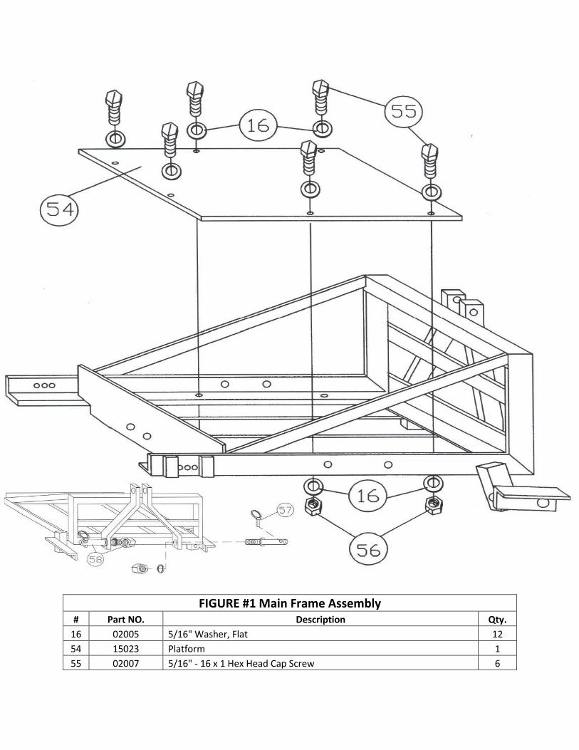
FIGURE #1 Main Frame Assembly # Part NO. Description Qty.
16 02005 5/16" Washer, Flat 12
54 15023 Platform 1
55 02007 5/16" - 16 x 1 Hex Head Cap Screw 6
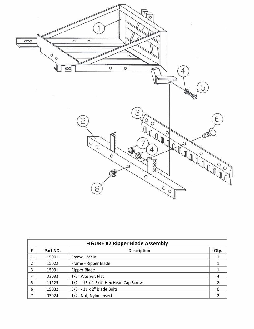
FIGURE #2 Ripper Blade Assembly # Part NO. Description Qty.
1 15001 Frame - Main 1
2 15022 Frame - Ripper Blade 1
3 15031 Ripper Blade 1
4 03032 1/2" Washer, Flat 4
5 11225 1/2" - 13 x 1-3/4" Hex Head Cap Screw 2
6 15032 5/8" - 11 x 2" Blade Bolts 6
7 03024 1/2" Nut, Nylon Insert 2
56 02004 5/16" Nut, Nylon Insert 6
57 15045 Pin, Lynch 2
58 15044 Pin, Hitch (includes nut & lock washer) 2
8 15033 5/8" Nut, Running 6
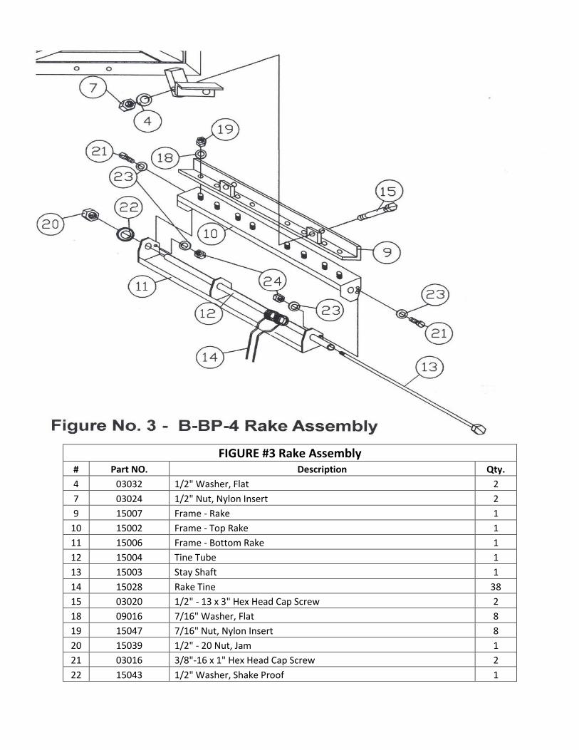
FIGURE #3 Rake Assembly # Part NO. Description Qty.
4 03032 1/2" Washer, Flat 2
7 03024 1/2" Nut, Nylon Insert 2
9 15007 Frame - Rake 1
10 15002 Frame - Top Rake 1
11 15006 Frame - Bottom Rake 1
12 15004 Tine Tube 1
13 15003 Stay Shaft 1
14 15028 Rake Tine 38
15 03020 1/2" - 13 x 3" Hex Head Cap Screw 2
18 09016 7/16" Washer, Flat 8
19 15047 7/16" Nut, Nylon Insert 8
20 15039 1/2" - 20 Nut, Jam 1
21 03016 3/8"-16 x 1" Hex Head Cap Screw 2
22 15043 1/2" Washer, Shake Proof 1
23 02024 3/8" Washer, Flat 4
24 03022 3/8" Nut, Nylon Insert 2
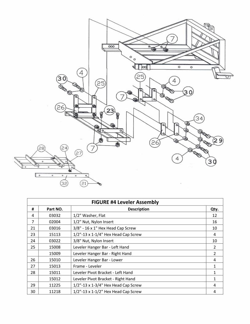
FIGURE #4 Leveler Assembly # Part NO. Description Qty.
4 03032 1/2" Washer, Flat 12
7 02004 1/2" Nut, Nylon Insert 16
21 03016 3/8" - 16 x 1" Hex Head Cap Screw 10
23 15113 1/2"-13 x 1-1/4" Hex Head Cap Screw 4
24 03022 3/8" Nut, Nylon Insert 10
25 15008 Leveler Hanger Bar - Left Hand 2
15009 Leveler Hanger Bar - Right Hand 2
26 15010 Leveler Hanger Bar - Lower 4
27 15013 Frame - Leveler 1
28 15011 Leveler Pivot Bracket - Left Hand 1
15012 Leveler Pivot Bracket - Right Hand 1
29 11225 1/2"-13 x 1-3/4" Hex Head Cap Screw 4
30 11218 1/2"-13 x 1-1/2" Hex Head Cap Screw 4
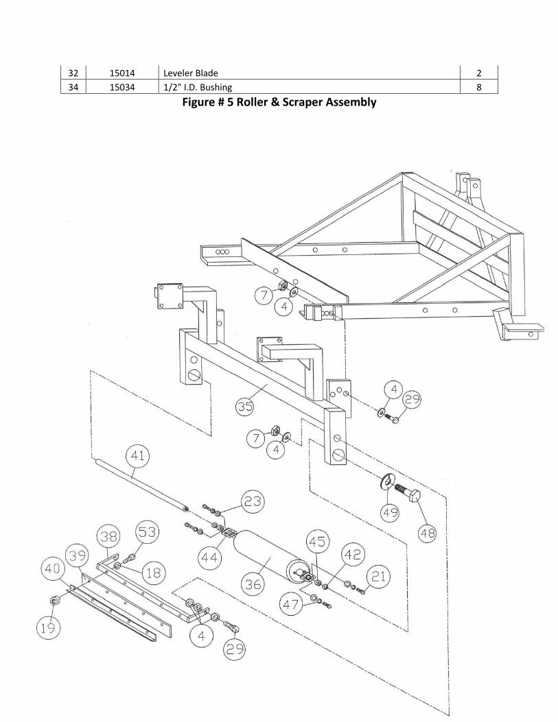
32 15014 Leveler Blade 2
34 15034 1/2" I.D. Bushing 8
Figure # 5 Roller & Scraper Assembly

FIGURE #5 Roller & Scraper Assembly # Part NO. Description Qty.
4 03032 1/2" Washer, Flat 12
7 03024 1/2"-13 Nut - Nylon Insert 4
18 02005 5/16" Washer - Flat 8
19 02004 5/16"-18 Nut, Nylon Insert 8
21 03016 3/8"-16 x 1" Hex Head Cap Screw 8
23 02024 3/8" Washer, Flat 8
29 11225 1/2"-13 x 1.75" Hex Head Cap Screw 2
35 15015 Frame - Roller 1
36 15026 Roller Half 2
38 15016 Frame - Scraper 1
39 15024 Rubber Scraper 1
40 15017 Clamp - Scraper 1
41 15025 Shaft - Roller 1
42 15040 Spacer - Thin (Inner) 3
43 15048 Spacer - Thick (Inner) 2
44 15027 Bearing 4
45 15019 Collar - Outer 2
47 03049 3/8" Washer - Lock 8
48 15041 3/4"-10 x 2" Hex Head Cap Screw 2
49 15042 3/4" Washer - Lock 2
53 03057 5/16" - 18 x 1.5" Hex Head Cap Screw 8

Figure # 6 Brush Assembly

FIGURE #6 Brush Assembly # Part NO. Description Qty.
4 03032 1/2" Washer, Flat 6
7 03024 1/2"-13 Nut - Nylon Insert 2
18 02024 3/8" Washer - Flat 18
19 03022 3/8"-16 Nut Nylon Insert 9
29 11225 1/2"-13 x 1.75" Hex Head Cap Screw 2
30 11218 1/2"-13 x 1.5" Hex Head Cap Screw 8
35 15015 Frame - Roller 1
37 15071 Frame - brush 1
51 11211 3/8"-16 x 3" Hex Head Cap Screw 9
52 15030 Brush 2
60 15103 Screw Jack Assembly 2
61 15111 5/8"-11 x 3" Hex Head Cap Screw 4
62 09024 5/8"-11 Nut - Nylon Insert 4
63 04037 5/8" Washer - Flat 8

Swing Away Wing Brush Kit

Swing Away Wing Brush Kit # Part NO. Description Qty.
1 15120 Brush Plate 2
2 15121 Pivot Plate 2
3 15061 Brush Bracket (L) 1
4 15059 Brush Bracket ( R) 1
5 15122 Nose Guard 2
6 15123 Eye Bolt Bracket 2
7 03064 Eye Bolt Bracket 5/16 x 3 2
8 15124 Chain 4 Link 2
9 15125 Sping - W.B. 2
10 15034 Bushing, 1/2" ID 4
11 11218 Bolt - 1/2"-13 x 1.5 Hex Head Cap 4
12 03032 Washer 1/2"SAE 8
13 03024 Nut, Nylon Insert 1/2"-13 4
14 03016 Bolt 3/8"-18 x 1" Hex Head Cap 4
15 02024 Washer - 3/8"SAE 20
16 03022 Nut, Nylon Insert 3/8"-16 12
17 11212 Bolt, 3/8"-18 x 3.25" Hex Head Cap 8
18 11210 Bolt 3/8"-18 x 2.5" Hex Head Cap 2
19 15053 Brush ( R) 1
20 15057 Brush (L) 1
21 03062 Nut, jam 3/8"-16 1
22 02007 Nut, Nylon Insert 5/16"-18 2
23 08078 Nut, Free Running 5/16"-18 2

Swing Away Wing Brush Kit # Part NO. Description Qty.
1 15150 Hydraulic Cylinder 1
2 15151 Hydraulic Hose 60" Length 2

3 15152 1/4" NPT Fitting 2
Optional Equipment
50 Gallon Water Tank Kit

Water Tank Kit # Part NO. Description Qty.
1 15201 Nozzle Mounting Bracket 1
2 15202 Tank Strap 2
3 15203 Nozzle Coupling Bracket 1
4 15204 Rubber Pad - tank Mounting 2
5 15205 Water Tank 1
6 15206 Filter Screen 1
7 15207 Adapter Barb 1
8 15208 90 Degree Elbow 3/8" MPT x 1/2" 2
9 15209 12 Volt Pump 1
10 15210 Pressure Switch 1
11 15211 Grommet 1
12 15212 Clamp 2
13 15213 90 Degree Elbow 1/2" x 1/2" 1
14 15214 Nozzle 4.0 Gallons per Minute 1
15 15215 Hose 1/2" x 24" 1
16 15216 Hose 1/2" x 40" 1
17 15217 Rubber Pad Strap 2
18 15200 Frame - Water Tank B-BP-6 1
19 01019 1/4"-20 x 1-1/2" Hex Head Cap Screw 4
20 02004 5/16"-18 Nut, Nylon Insert 4
21 02005 5/16" Washer, Flat 8
22 02007 5/16"-18 x 2-1/4" Hex Head Cap Screw 4
23 02024 3/8" Washer, Flat 2
24 02066 1/4"-20 Nut, Nylon Insert 3
25 03004 1/4"-20 x 1" Hex Head Cap Screw 3
26 03007 1/4" Washer, Flat 10
27 03022 3/8"-16 Nut, Nylon Insert 2
28 03024 1/2"-13 Nut, Nylon Insert 2
29 03032 1/2" Washer, Flat 2
30 11211 3/8"-16 x 3" Hex Head Cap Screw 2
31 11225 1/2"-13 x 1-3/4" Hex Head Cap Screw 2

Notes:

Notes:

Notes: