Embed Size (px)
Citation preview

00 300 1
CURB & CURB AND GUTTER
12/30/2011
11:1
0:0
6
AM
RE
VISIO
N
C:\
d\projects\standards\road
way\00300-s\00300-01.d
gn
NO.
SHEET
NO.
INDEX
rd960rh
DESCRIPTION:
REVISION
LAST
FY 2012/2013
FDOT DESIGN STANDARDS
Gutter Construction
Future Curb And
" Exp. Joint21
20’ R Or As Shown On Plans
*
*
*
*
" R43
*
*Fit Driveway
Slope To
Standard Shoulder Line
Roadway Pavement
CirculatingSpecified In The Plans
Truck Apron Surface
2"
"R811
Adjacent Pavement
Same Slope As
Joint Seal
Concrete PavementPreformed Joint Filler
" Exp. Joint And21
" R43
Joint Seal" R43
Conc. Pavt.
Preformed Joint Filler
" Exp. Joint And21
Joint Seal
Conc. Pavt.
Preformed Joint Filler
" Exp. Joint And21
TYPE B
TYPE D
TYPE A
TYPE E
TYPE F
DROP CURB
SHOULDER GUTTER
SECTION CC
SECTION BB
SECTION AA
PLAN
TYPE RA
VALLEY GUTTER
CONCRETE CURB
CONCRETE CURB AND GUTTER
ROUNDABOUT CENTRAL ISLAND CONSTRUCTION
TRAFFIC BEARING SECTION FOR USE IN
A
AB
B
C
C
Curb And GutterValley Gutter
1’-
10"
1’-
2"
1’-10" 1’-2"
" R
43
" R4
3
"4
16
3’-0"
"2
17
6"
Min.*
" Std.
21
7
6"
Min.*
" Std.
21
7
" R
43
"4
16
"2
17
5’-0"
8"
6"
1’-
0" 2"
R 3"
R
6" 1’-6" 1’-10" 1’-2"
1’-
0"
6"
2"
R
6" 1’-10" 1’-2"
3"
R
8"
3’-6"
"4
16
" R
43
6"
Min.*
" Std.
21
7
6"
Min.*
" Std.
21
7
1’-6"9"
11"
" R
431
" R
43 3"
5"
" R
43
2’-3"
6" 1’-6"
3"
R
2"
R
6"
1’-
0"
6"
8"
2’-0"
" R
43
"4
16
" R4
3
2’-0"
10" 1’-2"
1’ 6" 2’
3"
4"
" R4
3
7"
" R
43
7"
3’-6"
9"
" R
43
3"
1’-
0"
" R4
3
" R
43
9"
2’-3"
" R43
6"
2"R
18"
6"
8"
5"3"
" R43"
R43
1
18"
9"
16"
9" 7"
" R
43
" R
431
11"
" R
43
" R43
3"
5"
6"
flexible pavement, see diagram right.
For details depicting usage adjacent to
required between curbs and concrete pavement only, see Sheet 2.
shown. Expansion joint, preformed joint filler and joint seal are
For use adjacent to concrete or flexible pavement, concrete Note:
" R
43
6"
Min.*
" Std.
21
7
6"
Min.*
" Std.
21
7
Note: To be paid for as parent curb.
Earth Berm Shoulder Pavement
pavement only, see Sheet 2.
joint filler and joint seal are required between curb & gutter and concrete
usage adjacent to flexible pavement, see Sheet 2. Expansion joint, preformed
For use adjacent to concrete or flexible pavement. For details depicting
circulating roadway pavement.
Rotate entire section so that gutter cross slope matches slope of adjacent �
shall be 6", unless otherwise shown on plans.
match the cross slope of the adjacent pavement. The thickness of the lip
When used on high side of roadways, the cross slope of the gutter shall *
�

00 300 2
CURB & CURB AND GUTTER
12/30/2011
11:1
0:0
7
AM
RE
VISIO
N
C:\
d\projects\standards\road
way\00300-s\00300-02.d
gn
NO.
SHEET
NO.
INDEX
rd960rh
DESCRIPTION:
REVISION
LAST
FY 2012/2013
FDOT DESIGN STANDARDS
End Of Curb
Edge Of Pavt. Edge Of Pavt.
Top Of Curb
Gutter Gutter
Top Of Curb
End Of Curb
Edge Of Pavt. Edge Of Pavt.
Top Of Curb
Gutter
Top Of Curb
Gutter
" Min.212
Depth Of Sawcut
0" Min.
" Max.213
0" Min.
" Max.213
Depth Of Sawcut
Depth Of Sawcut
0" Min.
5" Max.
0" Min.
5" Max.
" Min.213
Depth Of Sawcut " Min.213
Depth Of Sawcut
" Min.213
Depth Of Sawcut
5" Max.
4" Min.,
3" Max.
2" Min.,
Rubbed
Cast Or
R=2"
Pitch Optional
" Holes43" Or 8
5
(Two Per Guard)
#4 Bars, 18" Long
�
Curb Or Curb & Gutter.
On High Side To Be Flush With Lip Of
" Above Lip Of Gutter. Surface41Be
Surface On Low Side Of Pavement to
Slope Varies
Flexible Pavt.
Joint Sea
Preformed Joint Fille
" Exp. Joint And21
Pavement
ConcreteGutter
Concrete
PLANPLANPLANPLAN
PROFILE
FLARED END
PROFILE
STRAIGHT END
CURB TYPE A
PROFILE PROFILE
FLARED END STRAIGHT END
CURB AND GUTTER TYPES E & F
SHOULDER GUTTER TYPE E
TYPE F
TYPE A
TYPE BTYPE D
GENERAL NOTES
CURB AND GUTTER ENDINGS
ADJACENT TO FLEXIBLE PAVEMENT
CURB AND GUTTER AND TYPE A CURB
CONTRACTION JOINT IN CURB
CONCRETE BUMPER GUARD ASPHALTIC CONCRETE CURB
CONTRACTION JOINT IN CURB AND GUTTER
AND CONCRETE PAVEMENT
EXPANSION JOINT BETWEEN GUTTER
Sawcuts should be avoided within valley gutter and within curb and gutter endings.
8.5’
20’
R
Trans.
3’
Trans.
3’
5.5’
6’
3’ Trans.
3’
Trans.
3’
Varie
s
" R43
" R
43
"211
5"
Min.,
6"
Max.
9" Max.
8" Min.,
3" Max.
2" Min.,12"(–)
6’-0"
2"5"2"
5"
9"
Applies to shoulder gutter only where adjoining traffic lanes.
Applies to both high and low sides of pavement, low side shown.�
� Applies to both high and low sides of pavement, low side s
2’–
20’
R
1’–
Ends of Curbs Types B and D shall transition from full to zero heights in 3’.2.
be located in accordance with Section 520 of the Standard Specifications.
to exceed 10’ centers. Curb, gutter and curb & gutter expansion joints shall
and flat curves are to match the pavement joints, with intermediate joints not
centers (max.). Contraction joints adjacent to concrete pavement on tangents
" contraction joints at 10’ 41" - 8
1For curb, gutter and curb & gutter provide 1.

07/01/05 301 1
TURN LANES
12/30/2011
11:1
0:0
8
AM
RE
VISIO
N
C:\
d\projects\standards\road
way\00300-s\00301-01.d
gn
NO.
SHEET
NO.
INDEX
rd960rh
DESCRIPTION:
REVISION
LAST
FY 2012/2013
FDOT DESIGN STANDARDS
Edge Of Turn Lane
(Curbed Section)
Edge Of Pavt.
Edge Of Turn Lane
(Curbed Section)
Edge Of Pavt.
(Curbed Section)
Edge Of Pavt.
Of Pavt.
Lane And Edge
Edge Of Turn
Of Pavt.
Lane And Edge
Edge Of Turn
2" Misc. Asphalt Pavt.(Refer To Index No. 300)
Concrete Curb Or Curb And Gutter
Begin Lane LineBegin Lane Line
Begin Lane Line Begin Lane Line
(Refer To Index No. 300)
Concrete Curb Or Curb And Gutter
(Refer To Index No. 300)
Concrete Curb Or Curb And Gutter
2" Misc. Asphalt Pavt.
Begin Lane Line
Begin Lane Line
Stop Bar (If Required)
Stop Bar (If Required)
TURN LANES • CURBED AND UNCURBED MEDIANS
DESIGN NOTES
GENERAL NOTES
TYPE E TYPE FCURB AND GUTTER
TYPE A TYPE B
CURB
TYPE D
FLUSH AND/OR CURBED SEPARATION
RAISED SEPARATION
RAISED SEPARATION
FLUSH AND/OR CURBED SEPARATION
DOUBLE LEFT TURNS
SINGLE LEFT TURNS
MEDIAN CURB AND TRAFFIC SEPARATOR JUNCTURE DETAILS
L3
Distance
Clearance
L
Distance
Decel.
Total
L2
Distance
Stop
Brake To
L3
Distance
Clearance
L
Distance
Decel.
Total
L2
Distance
Stop
Brake To
L1
Distance
Clearance
(mph)
Speed
Entry
(mph)
Speed
Design
URBAN CONDITIONS RURAL CONDITIONS
For pavement markings see Index No. 17346.5.
where specifically called for in the plans.
These left turn configurations apply to continuous left turn lanes only 4.
under free flow or yield conditions.
control conditions. Right turn lane tapers and/or distances are site specific
Right turn lane tapers and distances identical to left turn lanes under stop 3.
values are imposed by unrelocatable control points.
Total deceleration distances must not be reduced except where lesser 2.
shoulders nor separators specifically to either rural or urban conditions.
purposes only, they do not prescribe the use of curb, curb and gutter,
The plan views shown are for turn lane taper shapes and dimensional 1.
55 48 125’
135’ 240’
45 35 85’ 100’ 185’
35 25 70’ 75’ 145’
60
225’ 350’ 195’
135’
110’
65 55 170’ 290’ 460’
50
40 120’
160’ 160’
230’
270’
30
405’
290’
260’
185’
155’75’
145’
105’
80’
52
40/44
* Option I Separators Shown (Refer To Index No. 302)
For Curb And Curb & Gutter Types, See Index No. 300
Separator
8’-6" Traffic
Limits of 4’, 6’ or
Separator
8’-6" Traffic
Limits of 4’, 6’ or
Separator
8’-6" Traffic
Limits of 4’, 6’ or
* **
Separator
8’-6" Traffic
Limits of 4’, 6’ or
Separator
8’-6" Traffic
Limits of 4’, 6’ or
L1
L
L3
L2
Bar Location)
(Measured From Stop
Queue Length
10’
Bar Location)
(Measured From Stop
Queue LengthL2
L
L3
L1
L1
L
L2
Queue Length **
Taper 100
Taper 50
L1 L2
L Queue Length **
Taper 50
Taper 100
* *
Average Running Speed For Rural Condition
10 mph Below Design Speed For Urban Condition
Entry Speed:
Average Running Speed For Rural Condition
10 mph Below Design Speed For Urban Condition
Entry Speed:
Average Running Speed For Rural Condition
10 mph Below Design Speed For Urban Condition
Entry Speed:
Average Running Speed For Rural Condition
10 mph Below Design Speed For Urban Condition
Entry Speed:
10’
(AASHTO 2001 threshold rate of 11.2 ft./s†).
Comfortable deceleration rates for rural conditions •
75’ min. for L2.•
Minimum braking distance for urban conditions.•
Reaction preceding entry point.•
Wet Pavement.•
Stop condition (With Or Without Stop Control).•
Informed Driver.•
Basis for turn lane configurations:1.
Point Or, When A Stop Bar Is Required, From The Stop Bar.
Queue Length Is Measured From The Median Nose Radial **
Approved by District Design Engineer.c.
Through vehicle queues will not block access to left turn lane.b.
Left turn queue vehicles are adequately provided for within the design queue length.a.
The length of taper may be increased to L1 for single left turns and L3 for double left turns when:�
Turn Lane
Edge Of
Vehicle Clears Through Lane;
Brakes Applied After Turning
To Index No. 302)
Traffic Separator (Refer
Vehicle Clears Through Lane;
Brakes Applied After Turning
Delineator Post (Refer To Index No. 17346)
Delineator Post (Refer To Index No. 17346)
Vehicle Clears Through Lane;
Brakes Applied After Turning
To Index No. 302)
Traffic Separator (Refer
(Refer To Index No. 300)
Curb And Gutter
Concrete Curb Or
Vehicle Clears Through Lane;
Brakes Applied After Turning
07/01/07 302 1
TRAFFIC SEPARATORS
12/30/2011
11:1
0:0
8
AM
RE
VISIO
N
C:\
d\projects\standards\road
way\00300-s\00302-01.d
gn
NO.
SHEET
NO.
INDEX
rd960rh
DESCRIPTION:
REVISION
LAST
FY 2012/2013
FDOT DESIGN STANDARDS
(Same As Below)
Pitch
" For 8’-6" Separator435
" For 6’ Separator215
" For 4’ Separator415
" R431
Pavement
Flexible
Stabilized Subgrade
Pavement
Flexible
Stabilized Subgrade
" R431
Permitted (Typ.)
" Tool Edge41
Const. Joint With
" For 8’-6" Separator435
" For 6’ Separator215
" For 4’ Separator415
(Same As Below)
Pitch
(Same As Below)
Pitch
Pavement
Flexible " R431
Stabilized Subgrade
(Same As Below)
Pitch
" R431
Pavement
Flexible
" For 8’-6" Separator43
" For 6’ Separator21
" For 4’ Separator41
Filler & Joint Sealant
Joint (Preformed
" Expansion 21
" R431
"R43
Pavement
Cement Concrete
" For 8’-6" Separator43
" For 6’ Separator21
" For 4’ Separator41
"R43
Pavement
Cement Concrete
" R431
(Preformed Filler & Joint Sealant)
" Expansion Joint (Typ.)21
" For 8’-6" Separator435
" For 6’ Separator215
" For 4’ Separator415
(Same As Below)
Pitch
Pavement
Flexible
Subgrade
Stabilized
2"R
Subgrade
Stabilized
" For 8’-6" Separator435
" For 6’ Separator215
" For 4’ Separator415
(Same As Below)
Pitch
Pavement
Flexible
Permitted (Typ.)
" Tool Edge41
Const. Joint With
2" R
Dowels (12" Min., 18" Max.)
Separator Key In Lieu Of
" Min.)43Layer Of Structural Course (6
6" Plus Friction Course Or Upper
Price For Separator
The Contract Unit
To Be Included In
Dowel (Typ.) Cost
" Ø x6" Steel 21
Pavement
Flexible
Subgrade
Stabilized
Subgrade
Stabilized
(Same As Below)
Pitch
Of Dowels
Separator Key In Lieu
12" Min., 18" Max. Dowel
(Same As Below)
Pitch
Pavement
Flexible
" For 8’-6" Separator43
" For 6’ Separator21
" For 4’ Separator41
(Preformed Filler & Joint Sealant
" Expansion Joint21 " For 8’-6" Separator4
3
" For 6’ Separator21
" For 4’ Separator41
(Preformed Filler & Joint Sealant
" Expansion Joint (Typ.)21
Pavement
Cement Concrete "R43
Pavement
Cement Concrete
" R43
LONGITUDINAL SECTION (NOSE) TRANSVERSE SECTIONLONGITUDINAL SECTION (NOSE) TRANSVERSE SECTION
LONGITUDINAL SECTION (NOSE) TRANSVERSE SECTION
LONGITUDINAL SECTION (NOSE) TRANSVERSE SECTION
LONGITUDINAL SECTION (NOSE) TRANSVERSE SECTION
LONGITUDINAL SECTION (NOSE) TRANSVERSE SECTIONNOTES
OPTION II
OPTION IOPTION I
OPTION II
ROADWAY INSTALLATIONS
TYPE V CONCRETE TRAFFIC SEPARATOR
TYPE IV CONCRETE TRAFFIC SEPARATOR
TYPE I CONCRETE TRAFFIC SEPARATOR
TYPE II CONCRETE TRAFFIC SEPARATOR
2’, 3’ Or 4’-3" R
9" 1’-3", 2’-3"
Or 3’-6"
3"
5"
7"
5"
6"
7"
5"
3" 5
"
6"
5"
9"
4’-0", 6’-0" Or 8’-6"
9"
2’, 3’ Or 4’-3" R
9" 1’-3", 2’-3"
Or 3’-6"
3"
5"
5"
3"
9"9"
4’-0", 6’-0" Or 8’-6"
2’, 3’ Or 4’-3" R
1’-3", 2’-3"9"
Or 3’-6"
3"
5"
4"
6"
4"
5"
3"
9"
4’-0", 6’-0" Or 8’-6"
9"6"
2’, 3’ Or 4’-3" R
2" 1’-4", 2’-4"
Or 3’-7"
6"
6"
7"
6"
5"
4’-0", 6’-0" Or 8’-6"
6" 2"6"2"
5"
5"
6"
7"
6"
4’-0", 6’-0" Or 8’-6"
6" 2"
6"2"
3"
2"R6
"
In The Cost Of The Separator.
The Option II Separator Included
Cost Of The Flexible Pavt. Under
In The Cost Of The Separator.
The Option II Separator Included
Cost Of The Flexible Pavt. Under 2’, 3’ Or 4’-3" R
1’-4", 2’-4"
Or 3’-7"
6"2"
6"
Dowels 24" oc
2"R
2’, 3’ Or 4’-3" R
1’-10", 2’-10"
Or 4’-1"
2"
6"
4"
2"R 6
"
4’-0", 6’-0" Or 8’-6"
2"
2"
R6"
2"
6"
4"
than 4’, 6’ or 8’-6" shall be detailed in the plans as special separators and paid for under the contract unit price for Concrete Traffic Separator (Special) SY.
Separators having widths of 4’, 6’ or 8’-6" shall be paid for under the contract unit price for Concrete Traffic Separator (Type_) (_’ Wide) LF. Separators having widths other 4.
pavement joints, with intermediate joints not to exceed 10’ centers.
" contraction joints at 10’ centers (max.). Contraction joints adjacent to concrete pavement on tangents and flat curves are to match the 41"- 8
1For all separators provide 3.
Either Option I or Option II may be used for Types I and IV separators except when a specific option is called for in the plans.2.
Separators Type I and IV are to be used with flexible pavement. Separators Types II and V are to be used with rigid pavement.1.
Tool Edge Permitted
" 41Const. Joint With
" Min.)43Course (5
Upper Layer Of Structural
5" Plus Friction Course Or
" Min.)43Course (5
Upper Layer Of Structural
5" Plus Friction Course Or
Tool Edge Permitted
" 41Const. Joint With
Base Permitted)
(1" Min.) (To Top Of
Depth Varies
" Min.)43Layer Of Structural Course (6
6" Plus Friction Course Or Upper

01/01/11 302 2
TRAFFIC SEPARATORS
12/30/2011
11:1
0:0
9
AM
RE
VISIO
N
C:\
d\projects\standards\road
way\00300-s\00302-02.d
gn
NO.
SHEET
NO.
INDEX
rd960rh
DESCRIPTION:
REVISION
LAST
FY 2012/2013
FDOT DESIGN STANDARDS
Other Armored Joint Types Similar)
(Strip Seal Shown,
DETAIL AT EXPANSION JOINTS
BACKER ROD EXPANSION JOINTS
DETAIL AT POURED JOINT WITH
Expansion Joint at � Pier or Intermediate Bents Sim
(Deck Expansion Joint at Begin or End Bridge Shown,
APPROACH SLAB WITH TRAFFIC SEPARATOR
PARTIAL PLAN VIEW OF SKEWED BRIDGE DECK AND
ON BRIDGE DECKS WITH PRESTRESSING STEEL)
REINFORCING STEEL OPTION B (NOT PERMITTED
(Bridge Deck Shown, Approach Slab Similar)
SEPARATOR AT NOSE
LONGITUDINAL SECTION THRU TRAFFIC
(Bridge Deck Shown, Approach Slab Similar)
SEPARATOR AT NOSE
LONGITUDINAL SECTION THRU TRAFFIC
(Bridge Deck Shown, Approach Slab Similar)
TYPICAL SECTION THRU TRAFFIC SEPARATOR
(Bridge Deck Shown, Approach Slab Similar)
TYPICAL SECTION THRU TRAFFIC SEPARATOR
# Bars 4A (Typ.)
Approach Slab
Bridge Deck or
Joint
Construction
Riding Surface
Bars 4B @ 1"-6" O.C. (Max.) (Typ.)
Bars 4E @ 1"-6" O.C. (Max.) ##
or 3’-6"
1’-3", 2’-3",Bars 4A
Bars 4E (Typ.)
Joint
Construction
Approach Slab
Bridge Deck or
to maintain cover
rebar as required
Field bend and cut Bars 4B (Typ.)
1’-0" Max. sp. as required
(See Note 1)
Bars 4B or 4CApproach Slab
Approach Slab
Begin or End
Traffic Separator
Bridge Deck
or Bent
� Intermediate
" For 8’-6" Separator43
" For 6’-0" Separator21
" For 4’-0" Separator41* Pitch:
substituted for Bars 4B and 4E.
At the Contractor’s option a one piece bar may be ##
Bars 4A @ 7 equal spaces (continuous).For 8’-6" width:
Bars 4A @ 5 equal spaces (continuous).For 6’-0" width:
Bars 4A @ 3 equal spaces (continuous).For 4’-0" width: #
Joint
Construction
Riding Surface
Approach Slab
Bridge Deck or
O.C. (Max.) (Typ.)
Bars 4D @ 1’-6"
O.C. (Max.)
Bars 4C @ 1’-6" Bars 4A (Typ.) #
or 3’-6"
1’-3", 2’-3",
Joint
Construction
Bars 4C (Typ.)
Bars 4A
Bars 4D (Typ.)
Approach Slab
Bridge Deck or
to maintain cover
rebar as required
Field bend and cut
Joint Details)
Joint (See Expansion
Backer Rod Expansion
Poured Joint with
Separator (Typ.)
Traffic
Separator (Typ.)
Traffic
Details)
Expansion Joint
Assembly (See
Expansion Joint
See Structures Plans, Superstructure Sheets for actual dimensions and joint orientation. 3.
perpendicular or radial to the � of the Traffic Separator. See Structures Plans, Superstructure and Approach Slab Sheets for det
Traffic Separator ends at deck expansion joints shall follow the deck joint limits. Drainage joints and b" V-Grooves shall be placed 2.
Bars shall be field cut as shown, bars may be rotated to maintain clearance.
Traffic Separator transverse reinforcement adjacent to deck expansion joints shall be field adjusted to maintain clearance and spacing. 1.
Notes:
REINFORCING STEEL OPTION A
BRIDGE INSTALLATIONS - TYPE "E" CURB
4’-0", 6’-0", or 8’-6"
9"9"
5"
3"
3"
Min. (Typ.)
" Cover211 " (Typ.)4
3R = 1
2’-0" R, 3’-0" R, or 4’-3" R
9"
"43R = 1
5"
3"
*Pitch
See Reinforcing Steel Option A or B
for bar spacing
Typical @ Skewed Ends(Max.)
1’-6"
Deck Expansion
Joint
Min. (Typ.)
4’-0", 6’-0", or 8’-6"
9"9"(Typ.)
"43R = 1
" Cover211
* Pitch
* Pitch
* Pitch
5"
3"
"43R = 1
9"
2’-0" R, 3’-0" R, or 4’-3" R
3"
5"
3"
�

01/01/11 302 3
TRAFFIC SEPARATORS
12/30/2011
11:1
0:1
0
AM
RE
VISIO
N
C:\
d\projects\standards\road
way\00300-s\00302-03.d
gn
NO.
SHEET
NO.
INDEX
rd960rh
DESCRIPTION:
REVISION
LAST
FY 2012/2013
FDOT DESIGN STANDARDS
BACKER ROD EXPANSION JOINTS
DETAIL AT POURED JOINT WITH
Other Armored Joint Types Similar)
(Strip Seal Shown,
DETAIL AT EXPANSION JOINTS
(Bridge Deck Shown, Approach Slab Similar)
SEPARATOR AT NOSE
LONGITUDINAL SECTION THRU TRAFFIC
ON BRIDGE DECKS WITH PRESTRESSING STEEL)
REINFORCING STEEL OPTION B (NOT PERMITTED
(Bridge Deck Shown, Approach Slab Similar)
SEPARATOR AT NOSE
LONGITUDINAL SECTION THRU TRAFFIC
(Bridge Deck Shown, Approach Slab Similar)
TYPICAL SECTION THRU TRAFFIC SEPARATOR
(Bridge Deck Shown, Approach Slab Similar)
TYPICAL SECTION THRU TRAFFIC SEPARATOR
(Typ.)
R = 2"
Approach Slab
Bridge Deck or
# Bars 4A (Typ.)
Bars 4B @ 1"-6" O.C. (Max.) (Typ.)
Bars 4E @ 1"-6" O.C. (Max.) ##
Riding Surface
Joint
Construction
Approach Slab
Bridge Deck or
Bars 4E (Typ.)
Joint
Construction
Bars 4A
to maintain cover
rebar as required
Field bend and cut Bars 4B (Typ.)
Riding Surface
Approach Slab
Bridge Deck or
O.C. (Max.)
Bars 4C @ 1’-6"
O.C. (Max.) (Typ.)
Bars 4D @ 1’-6"Bars 4A (Typ.) #
Joint
Construction
Bars 4A
Joint
Construction
to maintain cover
rebar as required
Field bend and cut
Approach Slab
Bridge Deck or Bars 4D (Typ.)
" For 8’-6" Separator43
" For 6’-0" Separator21
" For 4’-0" Separator41Pitch: *
substituted for Bars 4B and 4E.
At the Contractor’s option a one piece bar may be ##
Bars 4A @ 7 equal spaces (continuous).For 8’-6" width:
Bars 4A @ 5 equal spaces (continuous).For 6’-0" width:
Bars 4A @ 3 equal spaces (continuous).For 4’-0" width: #
Separator (Typ.)
Traffic Separator (Typ.)
Traffic
Details)
Expansion Joint
Assembly (See
Expansion Joint
Joint Details)
Joint (See Expansion
Backer Rod Expansion
Poured Joint with
separators on skewed bridges, see Sheet 2.
shown. For additional notes and treatment of
Treatment of separators on straight bridges Note:
Bars 4C (Typ.)
*Pitch
REINFORCING STEEL OPTION A
BRIDGE INSTALLATIONS - TYPE "F" CURB
4’-0", 6’-0", or 8’-6"
2"
" Cover211
Min. (Typ.)
2"
* Pitch
6"
3"
2’-0" R, 3’-0" R, or 4’-3" R
1’-10", 2’-10", or 4’-1"2"
R = 2"
6"
* Pitch
4’-0", 6’-0", or 8’-6"
" Cover211
Min. (Typ.)
2"
R = 2"
(Typ.)
2"
6"
3"
R = 2"
2" 1’-10", 2’-10", or 4’-1"
2’-0" R, 3’-0" R, or 4’-3" R
6"
* Pitch

07/01/07 302 4
TRAFFIC SEPARATORS
12/30/2011
11:1
0:1
1
AM
RE
VISIO
N
C:\
d\projects\standards\road
way\00300-s\00302-04.d
gn
NO.
SHEET
NO.
INDEX
rd960rh
DESCRIPTION:
REVISION
LAST
FY 2012/2013
FDOT DESIGN STANDARDS
DETAILS (WELDED WIRE REINFORCEMENT)
ALTERNATE REINFORCING STEEL ESTIMATED TRAFFIC SEPARATOR QUANTITIES
STEEL BENDING DIAGRAMS
CONVENTIONAL REINFORCING
FOR 5" OPENING OR LESS
DRAINAGE JOINT DETAIL
(Between WWR 3 x 4 - W5.0 x W6.7 Sections)
SPLICE DETAIL
Length of Bars 4E is 6’-11" for 8’-6" Separator.
Length of Bars 4E is 4’-5" for 6’-0" Separator.
Length of Bars 4E is 2’-5" for 4’-0" Separator.
Note:
Length of Bars 4C is 6’-10b" for 8’-6" Separator.
Length of Bars 4C is 4’-4b" for 6’-0" Separator.
Length of Bars 4C is 2’-4b" for 4’-0" Separator.
Note:
equal to the wearing surface thickness.
be provided, increase this dimension by an amount
difference in thickness. If a wearing surface is to
decrease this dimension by an amount equal to the
wearing surface. If slab thickness is less than 8b",
are based on a slab 8b" thick or greater without a
The 8" vertical dimension shown for Bars 4B and 4D 2.
All dimensions are out to out.1.
Longitudinal Wire)
W5.0 (Lap Splice Each
W6.7 (Typ.)
W5.0W5.0
limited to the constant width section of separator.
of drainage joints. Locations for drainage joints shall be
See Structures Plans, Superstructure Sheets for location(s)
drainage joints.
centers (max.) equally spaced between expansion joints, and/or
b" V-GROOVES: For all separators provide b" V-Grooves at 30’-0"
use of slip forms without altering the separator dimensions shown.
the separator by the use of stationary removable forms or by the
TRAFFIC SEPARATOR CONSTRUCTION: The Contractor may construct
Concrete (Special), S.Y.
separators and paid under the contract unit price for Traffic Separator
than 4’-0", 6’-0", or 8’-6" shall be detailed in the plans as special
(Type II or V) (__’ Wide), LF. Separators having widths other
be paid under the contract unit price for Traffic Separator Concrete
PAYMENT: Separators having widths of 4’-0", 6’-0", and 8’-6" shall
REINFORCING STEEL: Reinforcing Steel shall be ASTM A615 Grade 60.
CONCRETE: See General Notes in Structures Plans.
NOTES:
of the Specifications.
system in accordance with Sections 416 and 937
2. Provide and install an adhesive bonding material
is encountered.
1. Shift Dowel Holes to clear if existing reinforcement
Dowel Notes:
Material System
Adhesive Bonding
Dowel Bar 4D
requirements
system manufacturer’s
adhesive bonding material
Hole diameter to meet
8’-6" Width - 9.45 Lbs. per Ft.
6’-0" Width - 7.00 Lbs. per Ft.
4’-0" Width - 4.77 Lbs. per Ft.
OPTION B:
8’-6" Width - 11.05 Lbs. per Ft.
6’-0" Width - 8.60 Lbs. per Ft.
4’-0" Width - 6.37 Lbs. per Ft.
OPTION A:
(All quantities are based on an 8b" slab.)
REINFORCING STEEL:
8’-6" Width = 0.403 CY - 0.536 CY
6’-0" Width = 0.193 CY - 0.257 CY
4’-0" Width = 0.080 CY - 0.109 CY
TYPE "E" TYPE "F"
NOSE:
8’-6" Width = 0.132 CY per Ft. - 0.164 CY per Ft.
6’-0" Width = 0.089 CY per Ft. - 0.112 CY per Ft.
4’-0" Width = 0.056 CY per Ft. - 0.072 CY per Ft.
TYPE "E" TYPE "F"
CONSTANT WIDTH OF SEPARATOR:
CONCRETE:
REINFORCING STEEL OPTION A
REINFORCING STEEL OPTION B
Bar 4BBars 4A & 4E
Bars 4A & 4C Bar 4D
DOWEL DETAIL
BRIDGE INSTALLATIONS - TYPE "E" AND "F" CURBS
Bars 4E
Bars 4A Length as required
See Note1’-0" 8" 1’-0"
8"
Bars 4C See Note
Bars 4A Length as required
6"
8"
REINFORCING STEEL NOTES:
Note: Welded Wire Reinforcement shall conform to ASTM A185.
Reinforcing Steel Option B.
required by plans in place of Bars 4A and 4C shown in
Use Welded Wire Reinforcement 3 x 4 - W5.0 x W6.7 as OPTION B:
shown in the Bending Diagram for Reinforcing Steel Option A.
Welded Wire Reinforcement to the dimensions of Bar 4B
required by plans in place of Bars 4A, 4B and 4E. Bend the
Use Welded Wire Reinforcement 3 x 4 - W5.0 x W6.7 as OPTION A:
Lap
1’-0" Min.
4" (Typ.)
10"
5"
�»

5"
Em
bed
ment Length

01/01/12 303 1
CURB RETURN PROFILES
12/30/2011
11:1
0:1
1
AM
RE
VISIO
N
C:\
d\projects\standards\road
way\00300-s\00303-01.d
gn
NO.
SHEET
NO.
INDEX
rd960rh
DESCRIPTION:
REVISION
LAST
FY 2012/2013
FDOT DESIGN STANDARDS
SHOWING LOCATION OF INLETS AT RETURNS
PROFILE VIEW
PLAN VIEW
TYPICAL RETURN PROFILES
Return
public sidewalk curb ramps for the disabled. For information on public sidewalk curb ramps refer to Index No. 304.
should be located to avoid conflict with pedestrian movement. Special care must be exercised to prevent conflict with
Profile grades should be established that will allow inlets to be located outside the return whenever practical. Inlets
Note:
Elev.
Ele
v.
InletReturn
Return
Inlet
Inlet Return Inlet
Ele
v.
High Elev.
Elev.
Low Elev.
Ele
v.
High Elev.
Elev.
Low Elev.
Ele
v.
Elev.

01/01/11 304 1
PUBLIC SIDEWALK CURB RAMPS
12/30/2011
11:1
0:1
2
AM
RE
VISIO
N
C:\
d\projects\standards\road
way\00300-s\00304-01.d
gn
NO.
SHEET
NO.
INDEX
rd960rh
DESCRIPTION:
REVISION
LAST
FY 2012/2013
FDOT DESIGN STANDARDS
Detectable Warning
Drop
�
Alignment Variations
Back Of Sidewalk
4’
Height Curb
2’ Min. Full
See Note Below
�
�
�
Height Curb
2’ Min. Full
CURB OPTIONS See Sheet 4.
And For RAMP AND SIDEWALK
OR BUFFER TRANSITIONS
For BACK OF SIDEWALK CURB
Curb Ramps
Omit Joints On4’ Min.
Ramp
LINEAR SIDEWALK RAMPS
TRANSITION
SIDEW
ALK / UTILITY STRIP
PICTORIAL VIEW
CURB RAMP NO
MENCLATURE
GENERAL NOTES
TYPICAL PLACEMENT OF PUBLIC SIDEWALK CURB RAMPS AT CURBED RETURNS
lanes.
ramp shall have a clear space 48" minimum outside active traffic
markings are present, the bottom of the ramp beyond the curb
within the markings of a marked crosswalk. If no crosswalk
beyond the curb line shall have a clear space 48" minimum
the projected crosswalk alignment. The bottom of the ramp
within crosswalk limits and where practical, be parallel with
When crosswalk markings are required, ramp runs must fall
Note:
Slope
Transition
Curb Transition
SlopeSi
dewalk
Existing
Utility Strip
(5’ Min.)
Varies
1:12
0.02
0.02
Trans.
Ramp
To 0.02 At The Flare Point.
The Sidewalk Shall Be Reconstructed To Reduce The Slopes
With Sidewalk Or Utility Strip Slopes Greater Than 0.02,
Where Curb Ram
ps Are Constructed In Existing Sidewalks
Slope
Tra
nsitio
n
0.02
1:1
2
1:12
0.02
1:1
2
1:12 0.0
2
0.02
Max.
1:1
2
0.02
1:12
0.02
1:12
0.0
2
1:12
0.0
2
may extend outside the return.
A portion of one or both ramps Note:
Utility Strip
Side Street
Turnout Or
to Index No. 17344 and 17346.
Crosswalk widths and configuration vary; must conform �
to be 1:12 shall be 1:12 maximum.
shall be 0.02 maximum. All ramp surfaces and ramp transition slopes with a slope shown in this Index
All sidewalk surfaces, ramp surfaces, and landings with a cross slope shown in this Index to be 0.02 10.
e. Surface may not deviate more than 0.10" from a true plane
d. No two adjacent domes may be non-compliant
c. There may be no more than 4 non-complying domes in any one square foot of surface
b. 90% of the individual truncated domes must comply with the design criteria
a. The ramp detectable warning surface shall be complete and uniform in color and texture
Acceptance Criteria for Detectable Warnings:9.
included in the contract unit price for new curb, curb and gutter and/or sidewalk respectively.
sidewalk is not provided in the plans, the cost of removal and disposal of these features shall be
When a separate pay item for the removal and disposal of existing curb, curb and gutter, and/or
Curb (Type __), LF or Concrete Curb and Gutter (Type __), LF.
reconstructed curbs are to be paid for under the contract unit price for the parent curb, i.e., Concrete
paid for under the contract unit price for Sidewalk Concrete, (__" Thick), SY. Curb transitions and
Ramps, reconstructed sidewalks, walk around sidewalks, sidewalk landings and sidewalk curbs are to be
Public sidewalk curb ramps are to be paid for as follows:8.
Alpha-numeric identifications are for reference (plans, permits, etc.).7.
no remaining section of sidewalk is less than 5’ long. For details of Concrete Sidewalk See Index 310.
shall be removed to the nearest joint beyond the transition slope or walk around or to the extent that
extent that no remaining section of curb or curb and gutter is less than 5’ long. The existing sidewalk
curb or curb and gutter shall be removed to the nearest joint beyond the curb transitions or to the
Where a curb ramp is constructed within existing curb, curb and gutter and/or sidewalk, the existing 6.
warnings on sidewalks at intersecting driveways, see Index 310.
required on sidewalks at intersecting roads, streets and railroads. For requirements for detectable
warning layouts. Transition slopes are not to have detectable warnings. Detectable warnings are
warning surfaces shall be constructed in accordance with Specification 527. See Sheet 6 for detectable
Curb ramp detectable warning surfaces shall extend the full width of the ramp and 24" deep. Detectable 5.
pedestrian traffic.
curb perpendicular to the sidewalk; improvements for guidance are not required at curb ramps for linear
returns may be used at locations where other improvements provide guidance away from that portion of
transition slopes to the ramp; the maximum slope of the transitions shall be 1:12. Ramps with curb
If a curb ramp is located where pedestrians must walk across the ramp, then the walk shall have 4.
greater length.
Ramp running slope is not required to exceed 8’ in length, except at sites where the plans specify a
provided.
with the requirements for cross slope cannot be fully met, the minimum feasible cross slope shall be
and a running slope of between 1:10 and 1:8 is permitted for a rise of 3" maximum. Where compliance
of a ramp slope of 1:12, a running slope between 1:12 and 1:10 is permitted for a rise of 6" maximum
When altering existing pedestrian facilities where existing site development precludes the accommodation
0.02 or flatter. Transition slopes shall not be steeper than 1:12.
Curb ramp running slopes at unrestrained sites shall not be steeper than 1:12 and cross slope shall be 3.
The location and orientation of curb ramps shall be as shown in the plans.2.
a landing constructed at the top of each ramp, see Sheet 5.
Index No. 515 to accommodate curb ramps. Ramps constructed at locations without sidewalks shall have
and at turnouts that have curbed returns. Partial curb returns shall extend to the limit prescribed by
sidewalks and those without sidewalks are to have curb ramps constructed at all street intersections
public right of way and to accessible pedestrian routes on adjacent sites. Curbed facilities with
continuous unobstructed pedestrian circulation paths to pedestrian areas, elements and facilities in the
Public sidewalk curb ramps shall be constructed in the public right of way at locations that will provide 1.
0.02

UTILITY STRIP
SIDEW
ALK WITH
UTILITY STRIP
SIDEW
ALK WITH
UTILITY STRIP
SIDEW
ALK WITH
UPPER LANDING AT NORMAL SIDEWALK ELEVATION
SECTION THROUGH RAMP RUN AND LANDINGS WITH
RAMP AND LANDING DEPTH ARE NOT RESTRICTED BY RIGHT OF WAY
DIMENSIONAL FEATURES FOR PUBLIC SIDEWALK CURB RAMPS WHERE
01/01/11 304 2
PUBLIC SIDEWALK CURB RAMPS
12/30/2011
11:1
0:1
3
AM
RE
VISIO
N
C:\
d\projects\standards\road
way\00300-s\00304-02.d
gn
NO.
SHEET
NO.
INDEX
rd960rh
DESCRIPTION:
REVISION
LAST
FY 2012/2013
FDOT DESIGN STANDARDS
Ramp And Sidewalk Curb
4’ Min.
Landing
(2’ Min.)
Util. Strip
Ramp And Sidewalk Curb
Landing 4’ Min.
(2’ Min.)
Util. Strip
Ramp And Sidewalk Curb
H
")41
(4’-2" To <7’-4
Utility Strip Varies
Ramp And Sidewalk Curb
Sidewalk Curb
*6"xH or 6"x12"
5’ Min.
5.6"
5’ Min.
Sidewalk Curb
*6"x5.6" or 6"x12"
Sidewalk Curb
*6"x5.6" or 6"x12"
5.6"
5’ Min.
(2’ Min.)
Grass Or Pavt.
Util. StripSidewalk Curb
*6"x2.8" or 6"x12"
5’ Min.
(2’ Min.)
Grass Or Pavt.
Util. Strip
4’ Min.La
nding
2.8"
Relieved Pavement
Not To Exceed 18"
Final Rolled Surface
Asphalt Pavement
(18" Max.)
Varies
Varies
Ramp
Relieved Pavement
5% max.
See Detail Below
Pavement Relief
Type ’F’ Curb And Gutter
14" When Located Along
2’ Detectable Warning
(2’ Min.)
Grass Or Pavt.
Util. Strip
Landing 4’ Min.
(2’ Min.)
Grass Or Pavt.
Util. Strip
4’ Min.
Landing
4’ Min.
4’ Min.
4’ Min.
4’ Min.
SIDEW
ALK
SIDEW
ALK
CR 6 CR 3
CR 1
CR 2CR 4CR 7
CR 8
CR 5
CR 9
SIDEW
ALK WITH CURBED
RETURNSPAVEMENT RELIEF AT LIP OF CURB
PICTORIAL
SIDEW
ALK
SIDEW
ALK WITH UTILITY STRIP
SIDEW
ALK
SIDEW
ALK WITH CURBED
RETURNS
SIDEW
ALK WITH CURBED
RETURNS
SIDEW
ALK WITH CURBED
RETURNS
SECTION
0.02
Swk.
5’ Std.
"41
=8’-6
Utility
max.1:
12
0.02
Grass
Grass
1:12
1:12
max.1:
12
Grass
Grass
0.02
0.02
Swk.
5’ Std.
" (Min.)
41
12’-6
3’4’Min. 3’
Swk.
5’ Std.
" (Min.)
41
12’-6
0.02
0.02
1:12
45°
1:12Grass
max.1:
12
Grass
0.02
1:120.02
1:12Grass
max.1:
12
Grass
0.02
Swk.
5’ Std.
Plan Dim
ensioning Required
1:12
max.0.
02
1:12
0.02
Swk.
6’ Min.
5’ Std.Sw
k.0.02
.02
1:12
1:12
max.0.
02
Swk.
5’ Std.
0.02
0.02
1:12
1:24
.02
1:24
1:12
max.1:
12
0.02
Swk. V
aries
Side
walk
Curb)
" Min.
With
81
(9’-4
" Min.)
81
(8’-1
0
(Max.)
1:12
(Max.)
1:12
max.5%
Smooth Milling; or, Grinding
Remove Elevated Pavement By Spading And Rolling;
" Shown)41Varies (12’-6
" Std.)41(7’-4
Ramp Varies
4’ (Min.)
Landing
0.02
1:12 max.
Exceed 8’ In Length)
(Not Required To
0.025% max.
3’
Min. 3’
45°
0.02
Swk.
6’ Std.
" (Min.)
41
12’-6
1:12
max.1:
12
1:12
0.02
0.025’
Std.Sw
k.
Swk.
5’ Std.
0.02
0.02
1:12
max.1:
12
1:12 0.02
Swk.
" (Min.)
41
12’-6
4’
SIDEWALK CURB OPTIONS See Sheet 4.
For BACK OF SIDEWALK CURB OR BUFFER TRANSITION And For RAMP AND *

UTILITY STRIP
SIDEW
ALK WITH
UTILITY STRIP
SIDEW
ALK WITH
UTILITY STRIP
SIDEW
ALK WITH
UPPER LANDING AT NORMAL SIDEWALK ELEVATION
SECTION THROUGH RAMP RUN AND LANDINGS WITH
RAMP AND LANDING DEPTH ARE RESTRICTED BY RIGHT OF WAY
DIMENSIONAL FEATURES FOR PUBLIC SIDEWALK CURB RAMPS WHERE
With S
wk. C
urb)"
Min.
21
(7’-5
(5’-11" Std.)
Ramp Varies
Exceed 8’ In Length)
(Not Required To
01/01/11 304 3
PUBLIC SIDEWALK CURB RAMPS
12/30/2011
11:1
0:1
3
AM
RE
VISIO
N
C:\
d\projects\standards\road
way\00300-s\00304-03.d
gn
NO.
SHEET
NO.
INDEX
rd960rh
DESCRIPTION:
REVISION
LAST
FY 2012/2013
FDOT DESIGN STANDARDS
Ramp And Sidewalk Curb
1:12
1:1
2
4’ Min.
Landing
(2’ Min.)
Util. Strip
Ramp And Sidewalk Curb
Landing 4’ Min.
(2’ Min.)
Util. Strip
Ramp And Sidewalk Curb
1:12
1:1
2
H
5’ Min.
(3’ Min.)
Util. Strip Varies
Sidewalk Curb
*6"xH or 6"x12"
Ramp And Sidewalk Curb
Sidewalk Curb
" or 6"x12"
21
*6"x4
"214
5’ Min.
5’ Min.
(2’ Min.)
Grass Or Pavt.
Util. Strip
"214
Sidewalk Curb
" or 6"x12"
21
*6"x4
1:12
1:12
Sidewalk Curb
" or 6"x12"
21
*6"x2
(2’ Min.)
Grass Or Pavt.
Util. Strip
(4’ Min.)
Landing
"412
5’ Min.
2’ Detectable Warning
(4’ Min.)
Landing
(2’ Min.)
Grass Or Pavt.
Util. Strip
Landing (4’ Min.)
(2’ Min.)
Grass Or Pavt.
Util. Strip
4’ Min.
4’ Min.
4’ Min.
4’ Min.
SIDEW
ALK
SIDEW
ALKCR 10
CR 11
CR 12
CR 13
CR 14
CR 15
CR 16
CR 17
CR 18
SIDEW
ALK
SIDEW
ALK WITH UTILITY STRIP
SIDEW
ALK
SIDEW
ALK WITH CURBED
RETURNS
SIDEW
ALK WITH CURBED
RETURNS
SIDEW
ALK WITH CURBED
RETURNS
SIDEW
ALK WITH CURBED
RETURNS
0.02
0.02
Grass
Grass
1:12 5’
-11"
=5’-1
1"Util. Strip 5’
Std.Swk.
0.02
.02
Grass
Grass
1:12
9’-1
1" (
Min.)5’
Std.Swk.
5’-1
1"
3’
4’Min. 3’
45°
0.02
.02
Grass
1:12 5’
-11"
Grass
Swk.
5’ Std.
9’-1
1" (
Min.)
Plan Dim
ensioning Required
1:12
.02
1:12
0.02
Swk.
5’ Std.
.02
Grass
1:12
Grass
Swk.
6’ Min.
0.02
1:120.02
1:12
Swk.
5’ Std..0
2
0.02
1:120.02
1:12
"Min.)
21
(6’-1
1
Swk.0.02
1:241:12
.02
1:24.02
0.02
5’ Std.Swk.
Varies (9’-11" Shown)
Landing
4’ (Min.)
0.025% max.
1:12 max.0.02
0.02
5’ Std.
Swk.
0.02
1:12
1:12 5’
-11"
1:120.02
9’-1
1" (
Min.)
5’ Std.
Swk.
0.02
.02
1:12
1:12 5’
-11"
1:12
0.02
6’ Min.Swk.
9’-1
1" (
Min.)
45°
3’
Min. 3’
4’
For BACK OF SIDEWALK CURB OR BUFFER TRANSITION And For RAMP AND SIDEWALK CURB OPTIONS See Sheet 4.*

CR 25 CR 24
CR 23
CR 20CR 21CR 22
SEPARATELY CAST CURBMONOLITHIC CAST CURB
PLAN
SECTION AA
CR 26
RAMPS UNDER CONDITIONS OF INFEASIBILITY
PUBLIC SIDEWALK COMBINED CORNER
DIMENSIONAL FEATURES FOR
DIMENSIONAL FEATURES FOR PUBLIC SIDEWALK CURB RAMPS FOR LINEAR PEDESTRIAN TRAFFIC
RAMP AND SIDEWALK CURB OPTIONS
OR BUFFER TRANSITION
BACK OF SIDEWALK CURB
A
A
0.02
1:121:12Ra
mp
4’
2’
R
4’
1:12Ra
mp
1:122’
R
0.02
1:1
2
Ra
mp2
’ R
Sidewalk
2’
R .02
1:12Ra
mp
0.02
0.02
1:12
Ramp
.02
2’
R
Landing
5’ Min.
0.02 1:1
2
(Min.)
4’
4’
(Min.)
0.0
2
1:12
0.02
1:12Ra
mp
.02
2’
R
Rdwy. Pavt. 2’
0.02
must conform to Index No. 17344 and 17346.
Crosswalk width and configuration vary; �
or 1:24
1:12
0.02
or 1:24
1:12
Buffer
R/W
6"
0.02 12"
6"
0.02
For In The Plans Or Standards
Maintainable Surface Contour, Abutting Structure, Or When Called
Construct Sidewalk Curb In Absence Of Adequate Buffer,
01/01/11 304 4
PUBLIC SIDEWALK CURB RAMPS
4’ Min.
4’
Min.
12/30/2011
11:1
0:1
4
AM
RE
VISIO
N
C:\
d\projects\standards\road
way\00300-s\00304-04.d
gn
NO.
SHEET
NO.
INDEX
rd960rh
DESCRIPTION:
REVISION
LAST
FY 2012/2013
FDOT DESIGN STANDARDS
Sidewalk (5’ Std.)
Util. Strip Grass Or Pavt. (2’ Min.)
45°
Sidewalk Curb
Ramp And
.02
Sidewalk (6’ Min.)
45°
Sidewalk Curb
Ramp And
.02
Sidewalk Curb
Ramp And
Sidewalk Curb
Ramp And
Sidewalk (5’ Std.)
Util. Strip Grass Or Pavt. (2’ Min.)
Sidewalk Curb
Ramp And
Sidewalk (6’ Min.)
Sidewalk Curb
Ramp And
Sidewalk (6’ Min.)
Exceed 8’ In Length)
1:12 (Not Required To
(Where Necessary)
Sidewalk Curb
�
�
(Where Necessary)
6" Sidewalk Curb
Landing
Sidewalk Curb
6" x 12" Separate
6" x H Monolithic or
Trans.
Drop (H)
" R43
Or Landing
Ramp, Sidewalk
H (Varies)
" R43
H (Varies)
Or Landing
Ramp, Sidewalk
Ramp Width (4’ Min.)Ramp Width (4’ Min.)
Ramp Width (4’ Min.) Ramp Width (4’ Min.)
Ramp Width (4’ Min.)

PLAN - (ALTERNATE DETAIL)PLAN
SECTION CC
C C
CC
THE CIRCULATION PATH TO PEDESTRIAN ROUTES ON ADJACENT SITES
SIDEWALKS ARE PART OF A CONTINUOUS PASSAGE OR WHERE A CURB FALLS ALONG
WHERE FUTURE SIDEWALKS ARE PROPOSED, WHERE STABLE SURFACES OTHER THAN
LANDINGS FOR RAMPS WITHIN PUBLIC RIGHT OF WAY CONSTRUCTED AT LOCATIONS
Slope
0.02 Max.
Landing
Concrete 0.02 Max. Slope
Concrete Landing
6’
5’
5’
5’
5’5’
Slope
0.02 Max.
Landing
Concrete
1:12 M
ax.
Ram
p Run
1:12 M
ax.
Ra
mp R
un
1:12 M
ax.
Ra
mp R
un
MEDIAN CROSSWALKS
01/01/11 304 5
PUBLIC SIDEWALK CURB RAMPS
12/30/2011
11:1
0:1
5
AM
RE
VISIO
N
C:\
d\projects\standards\road
way\00300-s\00304-05.d
gn
NO.
SHEET
NO.
INDEX
rd960rh
DESCRIPTION:
REVISION
LAST
FY 2012/2013
FDOT DESIGN STANDARDS
However, Slopes Shall Not Be Steeper Than 1:12.
Accommodate Other Construction In The Median;
For Variable Edge Of Pavement Elevations Or To
Equal. The Slopes May Intersect Off The Centerline
0.02 Rate When The Edge Of Pavement Elevations Are
Slopes Shall Intersect At Centerline Of Median On The
Roadway Pavement
Cross Walk (Concrete Sidewalk, 4")
(0.02 Std.; 1:12 Max.)
Slope Varies
¡ Median
Of 0.02 Can Be Constructed Adjacent To The Crosswalk.
The Crosswalk; Or, A 5’ x 5’ Concrete Landing With Maximum Slope
Crosswalk; The Refuge Can Be Constructed At Any Location Within
Slopes Of 0.05 Or Flatter And 5’ In Length Are Not Available On
5’ Refuge With Maximum Slope Of 0.02 Must Be Provided When
Gutter Type E Shown)
Curb Transition (Curb &Type E Shown)
(Curb And Gutter
Curb & Gutter Type E
Curb Types A Or B Or
Sidewalk
5’ Concrete
Median
2’ Curb Transition
Gutter) For Payment See General Note 8.
Remove And Reconstruct Curb Or Curb And
Curb Transition (On Existing Facilities
Median
Sidewalk
5’ Concrete
Type E Shown)
(Curb And Gutter
Curb & Gutter Type E
Curb Types A Or B Or
Other Options As Shown In The Plans
aligned with the centerline of the ramp. (See Pictorial View A)
On curb ramps, landings and flush transitions perpendicular to the curb line: Rows of domes shall be
01/01/11 304 6
PUBLIC SIDEWALK CURB RAMPS
12/30/2011
11:1
0:1
5
AM
RE
VISIO
N
C:\
d\projects\standards\road
way\00300-s\00304-06.d
gn
NO.
SHEET
NO.
INDEX
rd960rh
DESCRIPTION:
REVISION
LAST
FY 2012/2013
FDOT DESIGN STANDARDS
" Max.�212
Flangeway Gap
Median
(Where Necessary)
Sidewalk Curb
Warning
Detectable
Width
Rail Car
Gate
2’
2’
PICTORIAL VIEW
A
PICTORIAL VIEW
A
PICTORIAL VIEW
A
PLAN
PICTORIAL VIEW B PICTORIAL VIEW C
PICTORIAL VIEW CPICTORIAL VIEW B
PLAN
PLAN
Rail Road Crossing
TYPICAL PLACEMENT OF DETECTABLE WARNING AT CURB RAMPS
the ramp. (See Pictorial View C)
domes shall be aligned with the centerline of
On curb ramps at radius returns: Rows of
centerline of the ramp. (See Pictorial View B)
of domes are not required to be aligned with the
On landings and flush transitions at radius returns: Rows
from the back-of-curb.
ramp is no more than 5 feet
only if the bottom of the curb
bottom of the curb ramp, but
placed perpendicular across the
Detectable warnings may be *
Freight-only Railways
Up To 3" For
Flangeway Gap May Be �
Sidewalk
5’ Concrete
2’
2’
Ramp
2’
Utility Strip
2’Ra
mp
Utility Strip
Ramp
Landing
2’
Ram
p
Utility Strip
Utilit
y Strip
Ra
mp
2’ Ramp
Utility Strip
2’-
0"
Min.
6’-
0"
Max.
15’-
0"
Min.
4’-
0"
Sid
ewalk
6’
5’
Ramp
6’
5’
Ra
mp
2’
Landing
5’
Max.*
Utility Strip
5’
5’
Ra
mp
2’
Landing
5’
Max.*
Ra
mp
Utility Strip
5’
5’
07/01/09 305 1
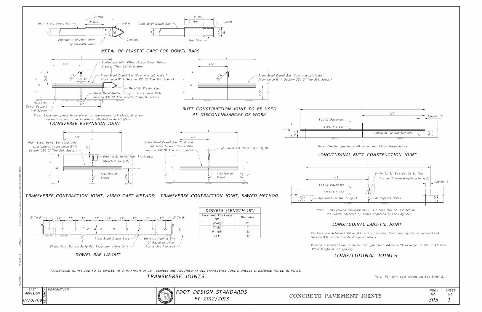
CONCRETE PAVEMENT JOINTS
12/30/2011
11:1
0:1
6
AM
RE
VISIO
N
C:\
d\projects\standards\road
way\00300-s\00305-01.d
gn
NO.
SHEET
NO.
INDEX
rd960rh
DESCRIPTION:
REVISION
LAST
FY 2012/2013
FDOT DESIGN STANDARDS
30" in length at 38" spacing.
Provide a standard load transfer tied joint with #4 bars 25" in length at 24" or #5 bars
Section 931 of the Standard Specifications.
Tie bars are deformed #4 or #5 reinforcing steel bars meeting the requirements of
L/2
"43
L/2
Plain Steel Dowel Bar
" On Both Sides81
Puncture And Push Down
Metal
Crimped
Plain Steel Dowel BarPlastic
Bar Stop
And Spacer
Dowel Support
Approved
Accordance With Section 350 Of The Std. Specs.)
Plain Steel Dowel Bar (Coat And Lubricate In
Section 931 Of The Standard Specifications
Sheet Metal Bottom Strip In Accordance With
Metal Or Plastic Cap
Greater Than Bar Diameter)
Preformed Joint Filler (Punch Clean Holes
Accordance With Section 350 Of The Std. Specs.)
Plain Steel Dowel Bar (Coat And Lubricate In
L/2 L/2
"8
1
Section 350 Of The Std. Specs.)
Lubricate In Accordance With
Plain Steel Dowel Bar (Coat And
Break
Anticipated
Section 350 Of The Std. Specs.)
Lubricate In Accordance With
Plain Steel Dowel Bar (Coat And
Break
Anticipated
D)31 to 4
1(Depth
" Max. Thickness)41Parting Strip (
D)31 to 4
1" Initial Cut (Depth 81
3" To 9" 3" To 9"
Plain Steel Dowel Bars
Sheet Metal Bottom Strip For Expansion Joints Only Forms Are Removed
Of Pavement After
Bend Up Against End
L/2
L/2
Top Of Pavement
Steel Tie Bar
Approved Tie Bar Support
Top Of Pavement
Steel Tie Bar
Approved Tie Bar Support Anticipated Break
D)31 to 4
1Formed Groove (Depth
" Max.41" Saw Cut Or 8
1Initial
L
METAL OR PLASTIC CAPS FOR DOWEL BARS
TRANSVERSE EXPANSION JOINT
TRANSVERSE CONTRACTION JOINT, VIBRO CAST METHOD TRANSVERSE CONTRACTION JOINT, SAWED METHOD
LONGITUDINAL BUTT CONSTRUCTION JOINT
LONGITUDINAL LANE-TIE JOINT
DOWEL BAR LAYOUT
AT DISCONTINUANCES OF WORK
BUTT CONSTRUCTION JOINT TO BE USED
DOWELS (LENGTH 18")
LONGITUDINAL JOINTS
TRANSVERSE JOINTS
Diameter"D"
Pavement Thickness
intersections and other locations indicated in detail plans.
Expansion joints to be placed on approaches to bridges, at street Note:
the plastic concrete by means approved by the Engineer.
Slabs poured simultaneously. Tie bars may be inserted in Note:
Note: For joint seal dimensions see Sheet 2.
TRANSVERSE JOINTS ARE TO BE SPACED AT A MAXIMUM OF 15’. DOWELS ARE REQUIRED AT ALL TRANSVERSE JOINTS UNLESS OTHERWISE NOTED IN PLANS.
3" Min.
2" Min.
"16
1d
+d
2" Min.
3" Min.
"16
1d
+
d
L
D
D/2
12"
" R
81
L
D
D/2
ID
ID
" R
81
L L
DD
D/2
D/2
12" 12" 12" 12" 12" 12" 12" 12" 12"
D/2
D
1"
"21 6"-6
"21 7"-8
"21 9"-10
"43
"411
"211=11"
Note: Tie bar spacing shall not exceed 24" at these joints.
D/2
Approx. 3"
D
D/2
L
D
D/2
D/2
Approx. 3"
�

00 305 2
CONCRETE PAVEMENT JOINTS
12/30/2011
11:1
0:1
6
AM
RE
VISIO
N
C:\
d\projects\standards\road
way\00300-s\00305-02.d
gn
NO.
SHEET
NO.
INDEX
rd960rh
DESCRIPTION:
REVISION
LAST
FY 2012/2013
FDOT DESIGN STANDARDS
As Specified In The Plans
Joint Sealant Material To Be
")81(w +
Tape Bond Breaker
Or Crack
Existing Joint
Saw Cut Or Formed Joint
"41" to 8
1 "41" to 8
1
" Max.3211"Min., 4
1
Saw Cut Or Formed Joint
Compression Seal
" Preformed Elastomeric169
Not Required For Construction Joints.
D (D=Conc. Pavt. Thick.)31 to 4
1
Saw Cut Or Parting Strip
"41" to 8
1
Backer Rod Placement Depth
Sealant Bead Thickness
Joint Depth
Joint Width
Backer Rod Bond Breaker
As Specified In The Plans
Joint Sealant Material To Be
"41" to 8
1
Saw Cut Joint
Asphalt Shoulder Pavement
As Specified In The Plans
Joint Sealant Material To Be
Backer Rod Bond Breaker
Concrete Pavement "41" to 8
1Concrete Pavement
Saw Cut Joint
Asphalt Shoulder Pavement
As Specified In The Plans
Joint Sealant Material To Be
")81(w +
Tape Bond Breaker
Or Existing Joints Or Cracks.
Required For Construction Joints
(D=Conc. Pavt. Thick.) Not
D31 to 4
1Saw Cut Or Parting Strip
TAPE BOND BREAKER
PREFORMED ELASTOMERIC COMPRESSION SEAL BACKER ROD BOND BREAKER
BACKER ROD BOND BREAKER TAPE BOND BREAKER
CONCRETE-CONCRETE JOINTS
CONCRETE-ASPHALT SHOULDER JOINTS
JOINT SEAL DIMENSIONS
FOR REHABILITATION PROJECTS
FOR NEW PROJECTS FOR NEW AND REHABILITATION PROJECTS
JOINT DIMENSIONS (INCHES)
WIDTH
JOINT
THICKNESS
BEAD
SEALANT
ROD DIA.
BACKER
DEPTH
JOINT
MINIMUM
DEPTH
PLACEMENT
BACKER ROD
CAN NOT BE ATTAINED
SHOULDER MUST BE REPAIRED IF PROPER JOINT SHAPE
EITHER TAPE OR BACKER ROD BOND BREAKER REQUIRED;
FOR NEW AND REHABILITATION PROJECTS;
(CONCRETE-CONCRETE JOINTS)
BACKER ROD BOND BREAKER
41
41
41
41
83
21
85
1
>1 21
21
83
165
83
21
85
1
811
411
+411
1
411
411
211
431
431
2
2+
21
21
21
85
field conditions.
on the plans or established by the Engineer based on
For rehabilitation projects the joint width will be shown
" for all other joints.83
" for construction joints,41for new construction will be
Unless otherwise indicated on the plans the joint width
value of 2.0 and a minimum value of 1.0.
so that the shape factor w/t has a maximum
conditions. Dimension d will be constructed
established by the Engineer based on field
Dimension w will be shown in the plans or Note:
w
d
t
"8
1"
–2
11
" Unless Specified Otherwise In The Plans43d = w =
w
t
d
" Unless Specified Otherwise In The Plans43d = w =
w
t
d
43
87
167
43
169
1611
43
43

00 305 3
CONCRETE PAVEMENT JOINTS
12/30/2011
11:1
0:1
7
AM
RE
VISIO
N
C:\
d\projects\standards\road
way\00300-s\00305-03.d
gn
NO.
SHEET
NO.
INDEX
rd960rh
DESCRIPTION:
REVISION
LAST
FY 2012/2013
FDOT DESIGN STANDARDS
Plastic Insert
Hook Bolt
Sleeve
Threaded
Inside Face Of Slip Form
To Form
Guide Bar Fastened
Hex Bolt
To Form
Guide Bar Fastened
" R81
Sealer
1:3 Slope
1"
0.25 D 0.375 D
Contraction Joints
Transverse Doweled
Contraction Joints
Transverse Doweled
Untied Keyed Joint
Joints
Tied Longitudinal
Untied Keyed Joint
Joints
Tied Longitudinal
Joints
Tied Longitudinal
Expansion Joint
Transverse Doweled
Untied Keyed Joint
Contraction Joint
Transverse Doweled
Spacer Bars
Filler Support Tie
Tie Wire
Center Spacer BarJoint Filler
Expansion Cap
Filler Support Wire
Joint Seal
D/2
Leg Staking Pin
Spacer Bars
Tie Wire
D/2
Staking Pin
Joint
Joint Filler
Preformed
ALTERNATE KEYWAY AND HOOK BOLT
KEYED JOINT
NOTES
STEEL HOOK BOLT ASSEMBLY
JOINT ARRANGEMENT
AT THRU INTERSECTION
JOINT LAYOUT
AT ’T’ INTERSECTIONS
JOINT LAYOUT
6" 8"
"87"8
7
"169
"16
9
2"
"87 1
"16
11
2"
"16
9
"169
"8
5
R
R
"41
0.1 D" D "
R
the State Construction Office in accordance with section (C) of the Product Evaluation Procedure.
Proprietary contraction and expansion assemblies may be used. Products shall be introduced to Note:
TOP VIEW
SECTION DD
SECTION CC
EXPANSION ASSEMBLY
D D
C
C
12" 12"
D
TOP VIEW
SECTION AA
SECTION BB
CONTRACTION ASSEMBLY
B B
A
A
12" 12"
D
" preformed expansion joint material.21All manholes, meter boxes and other projections into the pavement shall be boxed-in with 3.
Arrangement of longitudinal joints are to be as directed by the Engineer.2.
Longitudinal joints will not be required for single lane pavement 14’ or less in width. For entrance and exit ramp joint details, see Sheet 4.1.
to placing of concrete in the adjacent lane.
assembly shall be installed immediately prior
The remaining portion of the hook bolt
bolt and plastic insert shall be removed.
the Keyway will retain its shape, the hex
After the concrete has set to the extent that Note:
and meet the material and thread requirements of ASTM A 563.
Threaded sleeves shall develop the full strength of the bolt
Anchor bolts shall be Grade C in accordance with ASTM A 307.

07/01/09 305 4
CONCRETE PAVEMENT JOINTS
12/30/2011
11:1
0:1
8
AM
RE
VISIO
N
C:\
d\projects\standards\road
way\00300-s\00305-04.d
gn
NO.
SHEET
NO.
INDEX
rd960rh
DESCRIPTION:
REVISION
LAST
FY 2012/2013
FDOT DESIGN STANDARDS
* 13’ with tied Concrete Shoulders or 14’ with Asphalt Shoulders.
PCC Gore Pavt.
Longitudinal Joint Contraction Joint (Typ.)
PCC Gore Pa
vt.
Longitudinal Joint
Contraction Joint (Typ.)
Longitudinal Joint Contraction Joint (Typ.)
Wide Over 3 Slabs
Transition From 12’ to *
Contraction Joint (Typ.)Longitudinal Joint
Transition From * to 12’ Wide Over 3 Slabs
Contraction Joint (Typ.)
Longitudinal Joint
Longitudinal Joint
PCC Gore Pavt.
Contraction Joint (Typ.)
Contraction Joint (Typ.)
PCC Gore Pavt.
Transition From * to 12’ Wide Over 3 Slabs
Wide Over 3 Slabs
Transition From * to 12’
ENTRANCE TAPER WITH AUXILIARY LANE
2-THRU LANES WITH SINGLE LANE ENTRANCE RAMP
ENTRANCE RAMP WITH ADDED LANE
EXIT TAPER WITH AUXILIARY LANE
2-THRU LANES WITH SINGLE LANE EXIT RAMP
3-THRU LANES WITH AUXILIARY LANE AND 2-LANE EXIT RAMP
JOINT LAYOUT AT ENTRANCE AND EXIT RAMP TERMINALS
12’
* 3’
Min.
3’
Min.
3’
Min. 1
2’
*
50:1 Taper
Pavt.
RampPavt.
Mainline
12’
*
Ramp Pavt.
Mainline P
avt.
3’
Min.
3’
Min.
*12’
12’
*12’
3’
Min.
*
25:1 Taper
* 3’
Min.
12’
*Rate VariesAuxiliary Lane
12’
*
3’
Min.
3’
Min.
3’
Min.
Mainline Pavt. Ramp Pavt.
3’
Min.
12’
*
12’
12’
12’
* Auxiliary Lane
3’
Min.
3’
Min.
Mainline Pavt. Ramp Pavt.
*12’
*12’
12’
Note: On single lane ramps, longitudinal joint to
be constructed along centerline of ramp.
Auxiliary Lane
3’
Min.

04 306 1
BRIDGE APPROACH EXPANSION JOINT
CONCRETE PAVEMENT
12/30/2011
11:1
0:1
8
AM
RE
VISIO
N
C:\
d\projects\standards\road
way\00300-s\00306-01.d
gn
NO.
SHEET
NO.
INDEX
rd960rh
DESCRIPTION:
REVISION
LAST
FY 2012/2013
FDOT DESIGN STANDARDS
Shoulder Pavement
¡ Roadway
Join
¡ Expansion
(Doweled)
Construction Joint
Pavement
Shoulder
Join
¡ Expansion (Doweled)
Construction Joint
Bridge
Slab Details)
(See Approach
Skew Varies
Pavt.
Concrete Rigid Shoulder Pavt.
Compression Seal
Sheet Metal Strip
Subslab
Compression Seal
Concrete Pavt.
Sheet Metal Strip
Subslab
Seal
Compression ¡ Expansion Joint
Conc. Pavt.
*Class I Concrete
Conc. Pavt.
Sheet Metal Strip
Bars C
Bars D
Subslab
Or Grind 1#4" Chamfer
" Radius41Tool To
Concrete Pavement
Concrete Pavement
"21Plus
Seal Dimension
Manufacturer’s Specifications.
Seal Installed As Per
Polychloroprene Compression
DESIGN NOTES
GENERAL NOTES
PLAN
SECTION AA
WITH GRASSED SHOULDER OR FLEXIBLE SHOULDER PAVEMENT
WITH RIGID SHOULDER PAVEMENT
REINFORCING STEEL
JOINT DIMENSIONS
OPTIONAL SEALS
DETAIL SHOWING SHEET METAL STRIP
EXPANSION JOINT
COMPRESSION SEAL DETAIL
pavement joint included.
right angles to the centerline of the roadway pavement. Shoulder
Pay quantity of expansion joint to be calculated across pavement at 2.
constructed/reconstructed, and the location of expansion joints.
the number of slabs to be removed, the number of subslabs to be
For rehabilitation projects, the designer must indicate in the plans 1.
Bridge Approach Expansion Joint, LF.
Expansion joint to be paid for under the contract unit price for
reconstruction associated with joint replacement or reconstruction.
compression seal, but, not including roadway pavement
including reinforced concrete subslab, sheet metal strip and
expansion joint shall be full compensation for joint construction,
at right angles to the centerline of the roadway. Payment for
constructed across the roadway and shoulder pavements, measured
Pay quantity for expansion joint is the length of joint to be 3.
Index No. 305.
For information on other types of concrete pavement joints see 2.
the centerline of the roadway pavement shall be determined.
necessarily coincide. Prior to the placement of the expansion joint,
The centerline of roadway and the centerline of bridge do not 1.
to placing pavement.
second application immediately prior
pigmented curing compound. Apply
heavy coating of wax base white
Finish surface smooth. Cure with *
Designation G90.
accordance with ASTM A-526, Coating
steel, 12" wide and shall be galvanized in
The sheet metal strip shall be a minimum 16 gage
against the pavement edge.
is placed, sheet metal strip shall be bent up
foreign material. Immediately after the seal
joint shall be thoroughly cleaned of all
Immediately prior to placing the seal, the
Note:
thoroughly coated with a lubricant-adhesive.
compression seal and concrete shall be
All contacting surfaces between the Note:
Transverse Pavement Joints Shown In The Plans For New Construction.
Pavement Joints On Rehabilitation Projects, And Parallel To The Standard
Expansion Joints Shall Be Constructed Parallel To The Existing Transverse �
A A
30’ 15’ Varies
(W)
5’ Subslab5’ Subslab
Approach Slab
3"
"4
13
3"
"8
33
"32
13
3
3"
1"–
1"–
For Joint Payment See General Note No. 3.
To Bridge
Varie
s
9"
3" Cl.
5’-0"
(Center About Expansion Joint)
"2
14
LengthNo. Req.Spac.SizeMark
W Minus 6"6"5D
C 5 6" Varies 4’-6"
10
"412"
21
"211

01/01/10 307 1
MISCELLANEOUS UTILITY DETAILS
12/30/2011
11:1
0:1
9
AM
RE
VISIO
N
C:\
d\projects\standards\road
way\00300-s\00307-01.d
gn
NO.
SHEET
NO.
INDEX
rd960rh
DESCRIPTION:
REVISION
LAST
FY 2012/2013
FDOT DESIGN STANDARDS
Replacement Base
Accommodation Manual
Criteria In Utility
See Location
See Notes Below
Stage #1 Backfill *
In Pavement
Nearest Joint
For Butt Const. Joint
Refer To Index No. 305
Replacement Pavement
See Notes Below
Stage #1 Backfill *
See Notes Below
Stage #2 Backfill *
(Not Less Than 8" Thickness)
Match The Existing Pavement Thickness
Flowable Fill Option Is Used
#9 Stone Or Equivalent When
Utility Accommodation Manual
See Location Criteria In
GENERAL NOTES
RIGID PAVEMENT NOTES
PAVEMENT REMOVAL AND REPLACEMENTPAVEMENT REMOVAL AND REPLACEMENT
FLEXIBLE PAVEMENT NOTES
FLEXIBLE PAVEMENT CUT RIGID PAVEMENT CUT
* FLOWABLE FILL OPTION
GRANULAR BACKFILL
BACKFILL
* FLOWABLE FILL OPTION
COMPACTED AND STABILIZED FILL OPTION
TRENCH CUTS AND RESTORATIONS ACROSS ROADWAYS
the Contractor may construct using Optional Base Group 3.
of the base,with the upper 12" receiving Type B Stabilization. In lieu of Type B Stabilization,
In Stage #2, construct compacted fill along the sides of the pipe and up to the bottom
the haunches of the pipe and above any bedding.
tamps suitable for this purpose. This compaction applies to the material placed beneath
In Stage #1, construct compacted fill beneath the haunches of the pipe, using mechanical
Specifications.
Backfill material shall be placed in accordance with Section 125 of the Standard
pavement joints within 12 hours. (See Index No. 305)
Pavement shall be mechanically sawed and restored to conform with existing
of Standard Specification 346 shall be used for rigid pavement replacement.
High early strength cement concrete (3000 psi) meeting the requirements
of replacement pavement.
In Stage #2, construct fill along the sides of the pipe and up to the bottom
to the material placed beneath the haunches of the pipe and above any bedding.
using mechanical tamps suitable for this purpose. This compaction applies
In Stage #1, construct compacted fill beneath the haunches of the pipe,
Fill material shall be special select soil in accordance with Index No. 505.
Fill material shall be placed in accordance with the Standard Specifications.
methods approved by the Engineer.
materials. Any edgedrain system that is damaged shall be repaired with
Any edgedrain system that is removed shall be replaced with the same type
limits of the pavement and base.
and cover adjustments. Excavatable flowable fill shall not be used within the
non-excavatable flowable fill may be used for manhole stabilization and ring
When approved by the Engineer, in lieu of the pavement and base, 10.
selected.
Excavatable flowable fill is to be used when the flowable fill option is 9.
interruption and settlement potential.
engineering document shall address the evaluation of local groundwater flow
registered professional engineer that specializes in soils engineering. The
six (6) feet unless supported by an engineering document prepared by a
lengths. The maximum length shall be fifty (50) feet and a maximum depth of
straight or diagonal, and shall not be installed for significant depths or
allowed only when properly engineered for pavement crossings, whether
acceptable but must have prior approval by the Engineer. Flowable fill use is
The use of flowable fill to reduce the time traffic is taken off a facility is 8.
by utility trench cut construction shall be restored in kind.
All shoulder pavement, curb, curb and gutter, and their substructure disturbed 7.
structural course may be used in lieu of dense graded friction course.
replacement friction course shall match the existing friction course, except
slab. The overlay shall match the existing asphalt pavement thickness. The
replacement pavement shall have an overlay constructed over the replacement
Where asphalt concrete overlays exist over full slab concrete pavement, the 6.
Geotextiles may be required to encapsulate the special granular material.
Some pipe may require special granular backfill up to 6" above top of pipe. 5.
Method of construction must be approved by the Engineer. 4.
and backfill, or other special requirements.
roadway which may require the additional use of geotextiles, special bedding
These details do not apply to utility cuts longitudinal to the centerline of the 3.
flowable fill must be engineered to prevent pavement settlement.
Where highly compressible material exists, the amount, shape and depth of
material (see Index 505) which will cause settlement due to fill weight.
Flowable fill shall not be placed directly over loose, or high plastic, or muck 2.
bore or directional boring methods are not required by the Engineer.
The details provided in this standard index apply to cases in which jack and 1.
In Stage #2, place flowable fill to the bottom of the stone layer.
harden before placing Stage #2.
In Stage #1, place flowable fill midway up on both sides of the utility. Allow to
the Engineer.
flotation from occurring, Stages #1 and #2 can be combined, if approved by
Do not allow the utility being installed to float. If a method is provided to prevent
as approved by the Engineer.
Flowable fill is to be placed in accordance with Section 121 of the Specifications,
then flowable fill may be used.
If mechanical compaction can not be achieved through normal mechanical methods
In Stage #2, place flowable fill to the bottom of the existing base course.
placing Stage #2.
In Stage #1, place flowable fill midway up on both sides of the utility. Allow to harden before
flotation from occurring, Stages #1 and #2 can be combined, if approved by the Engineer.
Do not allow the utility being installed to float. If a method is provided to prevent
approved by the Engineer.
Flowable fill is to be placed in accordance with Section 121 of the Specifications, as
be used.
If compaction can not be achieved through normal mechanical methods then flowable fill may
Ditch Width (w) + 4’
Course & Friction Course
Replacement Structural
10’ Min. 10’ Min. Monolithic Slab 10’ Min.
24" Min.24" Min.
4" 12" 1
0"
12" Varies 12"
Ditch Width (w)
Varies12" 12"
18"
See
Notes Belo
w
Stage #
2 Backfill
*
the materials removed or of equal or greater structural adequacy (See Index No. 514).
The new base materials shall be either of the same type and composition as
and thickness in accordance with current FDOT asphalt mix specifications
The replacement asphalt shall match the existing structural and friction courses for type
Pavement shall be mechanically sawed.
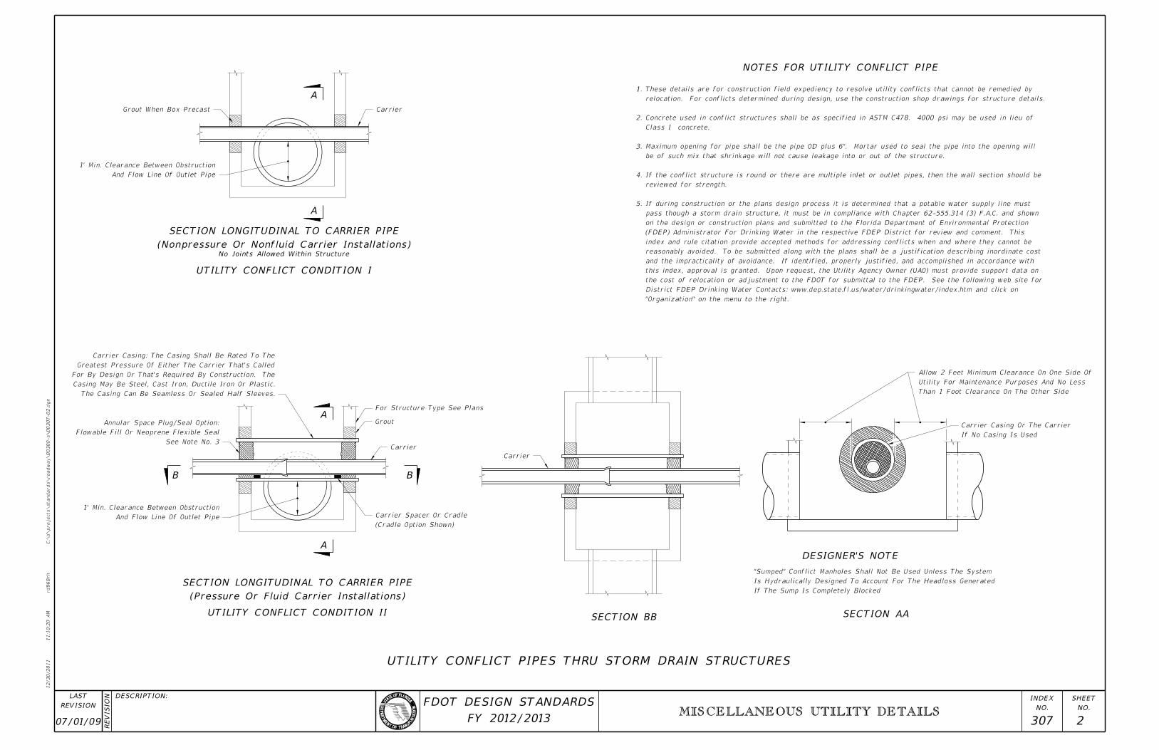
07/01/09 307 2
MISCELLANEOUS UTILITY DETAILS
12/30/2011
11:1
0:2
0
AM
RE
VISIO
N
C:\
d\projects\standards\road
way\00300-s\00307-02.d
gn
NO.
SHEET
NO.
INDEX
rd960rh
DESCRIPTION:
REVISION
LAST
FY 2012/2013
FDOT DESIGN STANDARDS
CarrierGrout When Box Precast
See Note No. 3
Flowable Fill Or Neoprene Flexible Seal
Annular Space Plug/Seal Option:
For Structure Type See Plans
Grout
Carrier
(Cradle Option Shown)
Carrier Spacer Or Cradle
Carrier
If No Casing Is Used
Carrier Casing Or The Carrier
The Casing Can Be Seamless Or Sealed Half Sleeves.
Casing May Be Steel, Cast Iron, Ductile Iron Or Plastic.
For By Design Or That’s Required By Construction. The
Greatest Pressure Of Either The Carrier That’s Called
Carrier Casing: The Casing Shall Be Rated To The
And Flow Line Of Outlet Pipe
1’ Min. Clearance Between Obstruction
And Flow Line Of Outlet Pipe
1’ Min. Clearance Between Obstruction
Than 1 Foot Clearance On The Other Side
Utility For Maintenance Purposes And No Less
Allow 2 Feet Minimum Clearance On One Side Of
NOTES FOR UTILITY CONFLICT PIPE
SECTION LONGITUDINAL TO CARRIER PIPE
A
A
UTILITY CONFLICT CONDITION I
UTILITY CONFLICT CONDITION II
A
B
A
B
SECTION BB SECTION AA
DESIGNER’S NOTE
UTILITY CONFLICT PIPES THRU STORM DRAIN STRUCTURES
SECTION LONGITUDINAL TO CARRIER PIPE
(Pressure Or Fluid Carrier Installations)
(Nonpressure Or Nonfluid Carrier Installations)No Joints Allowed Within Structure
If The Sump Is Completely Blocked
Is Hydraulically Designed To Account For The Headloss Generated
"Sumped" Conflict Manholes Shall Not Be Used Unless The System
"Organization" on the menu to the right.
District FDEP Drinking Water Contacts: www.dep.state.fl.us/water/drinkingwater/index.htm and click on
the cost of relocation or adjustment to the FDOT for submittal to the FDEP. See the following web site for
this index, approval is granted. Upon request, the Utility Agency Owner (UAO) must provide support data on
and the impracticality of avoidance. If identified, properly justified, and accomplished in accordance with
reasonably avoided. To be submitted along with the plans shall be a justification describing inordinate cost
index and rule citation provide accepted methods for addressing conflicts when and where they cannot be
(FDEP) Administrator For Drinking Water in the respective FDEP District for review and comment. This
on the design or construction plans and submitted to the Florida Department of Environmental Protection
pass though a storm drain structure, it must be in compliance with Chapter 62-555.314 (3) F.A.C. and shown
If during construction or the plans design process it is determined that a potable water supply line must 5.
reviewed for strength.
If the conflict structure is round or there are multiple inlet or outlet pipes, then the wall section should be 4.
be of such mix that shrinkage will not cause leakage into or out of the structure.
Maximum opening for pipe shall be the pipe OD plus 6". Mortar used to seal the pipe into the opening will 3.
Class I concrete.
Concrete used in conflict structures shall be as specified in ASTM C478. 4000 psi may be used in lieu of 2.
relocation. For conflicts determined during design, use the construction shop drawings for structure details.
These details are for construction field expediency to resolve utility conflicts that cannot be remedied by 1.

04 307 3
MISCELLANEOUS UTILITY DETAILS
12/30/2011
11:1
0:2
1
AM
RE
VISIO
N
C:\
d\projects\standards\road
way\00300-s\00307-03.d
gn
NO.
SHEET
NO.
INDEX
rd960rh
DESCRIPTION:
REVISION
LAST
FY 2012/2013
FDOT DESIGN STANDARDS
Or Uncurbed Divided Facility
Median Edge Of Pavement On Curbed
*
*
Manhole
*
Manhole
*
Manhole
Transverse Cut Line
Transverse Cut Line
(Outside Wheel Path Where Practical)
Longitudinal Cut Line
Longitudinal Cut Line
One-Way Facility Or Type F Curb On Divided Facility
Curb And Gutter On Two-Lane Two-Way Facility Or
PLAN VIEW
NOTES
PARTIAL CUTS FOR RING AND COVER ADJUSTMENTS
FOR TWO OR MORE LANES (TWO LANES SHOWN)
NONTRENCH PAVEMENT CUTS FOR UNDERGROUND UTILITY STRUCTURES IN PAVEMENT
See Sheet 1 for replacement pavement.3.
shall extend to the nearest existing joint.
pavement are the same longitudinally, but the transverse seams
Pavement cut seams for underground utility structures in rigid 2.
No irregular seams are permitted. All seams must be clean sawed.1.
With A Regular Seam Or Midlane Point In Order To Be Outside The Wheel Path
Longitudinal Cut Lines For Both Curbed And Uncurbed Facilities Must Coincide *
4’ Min.
Excavation
Ring & Cover
MH Or 4’ Min.
yx
2x
2y
(4’
Min.)
Varie
s
(4’
Min.)
Varie
s

01/01/11 308 1
CONCRETE SLAB REPLACEMENT
12/30/2011
11:1
0:2
1
AM
RE
VISIO
N
C:\
d\projects\standards\road
way\00300-s\00308-01.d
gn
NO.
SHEET
NO.
INDEX
rd960rh
DESCRIPTION:
REVISION
LAST
FY 2012/2013
FDOT DESIGN STANDARDS
Existing Longitudinal Joint
Crack
Transverse
Existing Transverse Joint
Existing Transverse Joint
Existing Longitudinal Joint Epoxy Saw Overrun (Typ.)
Control Joint
Transverse
Between Existing Dowel Bar Locations)
New Dowel Bars (Equally Spaced
(Along All Longitudinal and Transverse Joints)
Bond Breaker
12" (Typ.)
12" (Typ.)
(Along All Longitudinal and Transverse Joints)
Bond Breaker
Between Existing Dowel Bar Locations)
New Dowel Bars (Equally Spaced
Existing Transverse Joint
During Slab Replacement
Epoxy Saw Overrun (Typical)
Repair Area
Full-Depth
(Along All Longitudinal and Transverse Joints)
Bond Breaker
Existing Transverse Joint
Repair Area
Full-Depth
Existing Longitudinal Joint
12" (Typ.)
Between Existing Dowel Bar Locations)
New Dowel Bars (Equally Spaced
Epoxy Saw Overrun (Typ.)
FIGURE 10.5 - FULL-DEPTH REPAIR ON BOTH SIDES OF THE JOINT
FIGURE 10.2 - REPAIR METHOD: NONE OR CLEAN AND SEAL
FIGURE 10.3 - FULL SLAB FULL DEPTH REPLACEMENT
FIGURE 10.4 - PARTIAL SLAB FULL DEPTH REPLACEMENT
GENERAL NOTES
6’-0" (Min.) 6’-0" (Min.)
L21
(10’-0" Max.)
L
6’-0" (Min.) Remainder
6’-0" (Min.)
6’-0" (Min.)
Remainder
6’-0" (Min.)
epoxy.
During slab replacement operations, fill any saw cut over runs into adjacent slabs with 7.
first.
If the roadway contract includes grinding, then the slab replacement shall be performed 6.
replaced by the contractor at his expense.
pavement which is damaged during removal of damaged areas shall be removed and
Removal of the damaged concrete pavement shall be by lifting. Any good concrete 5.
grade.
be allowed for additional concrete required to bring proposed concrete slab up to finished
shall be placed to the full depth of the material removed. No additional compensation will
material shall be removed prior to placement of the new concrete slab. The concrete slab
No additional base or subgrade material shall be added and all loose base or subgrade 4.
to penetrate more than 0.5 in. into the base.
the wheel saw cuts. To prevent damage to the base, the wheel saw must not be allowed
joints. Hence, if wheel saw cuts are made, diamond saw cuts must be made 18 in. outside
repair. The wheel saw cuts produce a ragged edge that promotes excessive spalling along
but the wheel saw must not intrude on the adjacent lane, unless the lane is slated for
within the repair boundaries. A carbide-tipped wheel saw may be used for this purpose,
may not be possible to make this cut without first making a wide, pressure relief cut
Repair boundaries shall be sawed full-depth with diamond saw blades. On hot days, it 3.
slab to the bottom of the concrete.
Full depth repairs consist of removing and replacing at least a portion of the existing 2.
For Repair and Replacement Criteria see Sheet 2.1.

07/01/10 308 2
CONCRETE SLAB REPLACEMENT
12/30/2011
11:1
0:2
2
AM
RE
VISIO
N
C:\
d\projects\standards\road
way\00300-s\00308-02.d
gn
NO.
SHEET
NO.
INDEX
rd960rh
DESCRIPTION:
REVISION
LAST
FY 2012/2013
FDOT DESIGN STANDARDS
SLAB REPAIR AND REPLACEMENT CRITERIA
DISTRESS PATTERN SEVERITY/DESCRIPTION REPAIR METHOD REFERENCE
CRACKING
JOINT DEFICIENCIES
SURFACE DETERIORATION
MISCELLANEOUS DISTRESS
Longitudinal
Transverse
Corner Breaks
(Shattered Slab)
Intersecting Random Cracks
Spall Nonwheel Path
Spall Wheel Path
Pop Outs Nonwheel Path
Pop Outs Wheel Path
Faulting
Water Bleeding Or Pumping
Blowups
Lane To Shoulder Drop-Off
Light
Moderate
Severe
Light
Moderate
Severe
45° angle with the direction of traffic.
adjacent longitudinal and transverse joint, describing an approximate
A corner of the slab is separated by a crack that intersects the
Cracking patterns that divide the slab into three or more segments.
Light
Moderate
Severe
Light
Moderate
Severe
to 2 in. in depth.21from 1 to 4 in. diameter and
Small pieces of surface pavement broken loose, normally ranging
Light
Severe
>3" diameter and 2" in depth.
Small pieces of surface pavement broken loose, normally
Light
Severe
Elevation differences across joints or cracks.
Light
Moderate
Severe
Light
Moderate
Severe
Seeping or ejection of water through joints or cracks.
accompanied by shattering of the concrete.
Upward movement at transverse joints or cracks often
permeable subbase, reseal joints, etc.
Install appropriate drainage, edge drain,
Figure 10.2
Figure 10.3
None
Clean and Seal
Replace
None
Clean and Seal
Replace
Figure 10.2
Figure 10.3, 10.4 and 10.5
Figure 10.4 and 10.5
None
None
Figure 10.3 and 10.4
None
Full Depth
Full Depth
Figure 10.4 and 10.5
Keep under observation
Figure 10.4
Figure 10.4
Figure 10.4
None
Grind
Grind
None
N/A
Figure 10.3 and 10.4
Figure 10.4 and 10.5
Figure 10.4 and 10.5
Figure 10.4 and 10.5
Figure 10.4 and 10.5
Figure 10.4 and 10.5
Build Up
Build Up
N/A
Figure 10.2
Full Depth
Full Depth
Full Depth
Full Depth
Full Depth
Full Depth
Full Depth
" wide21", no faulting, spalling <8
1<
", spalling <3" wide21" <width <8
1
"21", spalling >3" faulting >2
1width >
" wide21", no faulting, spalling <8
1<
", spalling <3" wide21" <width <8
1
"21", spalling >3" faulting >2
1width >
spall width >3" or length >12"
spall width >3" or length >12"
Not deemed to be a traffic hazard
Flying debris deemed a traffic hazard
Deemed to be a traffic hazard
Flying debris deemed a traffic hazard
Faulting <4/32"
4 <Faulting <16/32"
Faulting >16/32"
0 <drop-off <1"
1" <drop-off <3"
drop-off >3 "
slab depth, <12" in length31" <spall width <3", < 2
11
slab depth, <12" in length31", < 2
1spall width <1
slab depth, <12" in length31", <than 2
1spall width <1
slab depth, <12" in length31" <spall width <3", < 2
11

1 01/01/10 310
CONCRETE SIDEWALK
12/30/2011
11:1
0:2
2
AM
RE
VISIO
N
C:\
d\projects\standards\road
way\00300-s\00310-01.d
gn
NO.
SHEET
NO.
INDEX
rd960rh
DESCRIPTION:
REVISION
LAST
FY 2012/2013
FDOT DESIGN STANDARDS
"21"2
1
"21
"21
Return Curb
Rigid Structure; 6" Min. For Turnouts
Rigid Structure; 6" Min. For Turnouts
Return Curb
45°
A A
A
A A
A
A (Utility Pole, Ex.)
Sidewalk
Utility Strip Utility Strip
Sidewalk
Curb Or Curb And Gutter
A
A
A
Back Of Sidewalk Variations
Omit Joints On Curb Ramps
A (Signal Pole Or Controller Base, Ex.)
Flush-Tooled Edge
A A
AG G
AA
ATurnout
Sidewalk
A (Utility Pole, Ex.)
Sidewalk
And Gutter
Curb or Curb G
A
A
A
Back Of Sidewalk Variations
Omit Joints On Curb Ramps
A (Signal Pole Or Controller Base, Ex.)
G
860, 870 & 880
Pipe Guiderail See Index Nos. 850,
Pedestrian/Bicycle Picket Railing Or
4’
4’
4’
4’
SURFACE MOUNTED RAILINGS
SIDEWALK WITH EDGE BEAM FOR
OPEN JOINTS
LONGITUDINAL SECTION
SIDEWALK JOINTS
JOINT LEGEND
NOTES FOR CONCRETE SIDEWALK ON CURBED ROADWAYS
SIDEWALK WITHOUT UTILITY STRIP
SIDEWALK WITH UTILITY STRIP
SECTION BB
SECTION AA
CONCRETE SIDEWALK FOR CURBED ROADWAYS
EXAGGERATED SCALE
SAWED JOINTS
Sidewalk shall be paid for under the contract unit price for Sidewalk Concrete (___Thick), S.Y. 5.
Pedestrian/Bicycle Picket Railing or Pipe Guiderail shown in the plans.
Construct sidewalks with 1’ thick Edge Beam through the limits of any surface mounted 4.
For turnouts see Index No. 515.3.
".21material having a thickness of not less than 6 mils nor more than
Bond breaker material can be any impermeable coated or sheet membrane or preformed 2.
sidewalks intersect urban flared turnouts.
constructed in accordance with Index No. 304. Detectable warnings are not required where
Specifications. Public sidewalk curb ramps shall include detectable warnings and be
Sidewalks shall be constructed in accordance with Section 522 of the FDOT Standard 1.
Cold Joint With Bond Breaker, TooledG-
Intermediate locations when called for in the plans or at locations as directed by the Engineer.
" Expansion Joint When Run Of Sidewalk Exceeds 120’.21F-
" Deep (within 12 hours) Max. 30’ Centers21" Saw Cut Joints, 116
3E-
" Deep (within 96 hours) Max. 5’ Centers21" Saw Cut Joints, 116
3D-
" Formed Open Joints81C-
" Dummy Joints, Tooled81B-
" Expansion Joints (Preformed Joint Filler)21A-
120’ Max.
30’ Max.30’ Max. 30’ Max.
A D D D D D E D D F D D A
5’5’5’5’5’5’5’5’5’5’
4"
8"
A B C B C B C B C B A
8"
4"
0.02 Max.
1’-
0"
9"
On Railings Used.)
(Total Width May Vary Based
Sidewalk
(Cost Of Edge Beam To Be Included In Price Of Sidewalk)
Strip
Utility
Varies
Sidewalk
Varies (5’ Std.)
0.02 0.02 Max.
TurnoutTurnout
(Full Return Shown)
Turnout Or Side Street
A
A
GSidewalk
Varies (6’ Min.)
0.02 Max.
Turnout
B
B (Full Return Shown)
Turnout Or Side Street
(5’ or 6’ Std., 4’ Min.)
Clear Width
120’ Max.
NOTE: "E" Joint(s) Required When Length Exceeds 30’

07/01/09 310 2
CONCRETE SIDEWALK
12/30/2011
11:1
0:2
3
AM
RE
VISIO
N
C:\
d\projects\standards\road
way\00300-s\00310-02.d
gn
NO.
SHEET
NO.
INDEX
rd960rh
DESCRIPTION:
REVISION
LAST
FY 2012/2013
FDOT DESIGN STANDARDS
Flexible Pavt.
Rigid Pavt.
Flexible Pavt.
Rigid Pavt.
Sidewalk
Shoulder Line
Edge Of Traveled Way
�
Edge Of Traveled Way
Shoulder Line
Sidewalk
Warning Surface
2’ Detectable
Warning Surface
2’ Detectable
Warning Surface
2’ Detectable
NOTES FOR CONCRETE SIDEWALKS ON UNCURBED ROADWAYS
CONTINUOUS SIDEWALK
DISCONTINUOUS SIDEWALK
PLAN
OPEN JOINTS
LONGITUDINAL SECTIONS
SAWED JOINTS
JOINT LEGEND
SECTION CC
C
C
EXAGGERATED SCALE
CONCRETE SIDEWALK FOR UNCURBED ROADWAYS
SIDEWALK JOINTS
Sidewalk shall be paid for under the contract unit price for Sidewalk Concrete (___Thick), SY.5.
Pedestrian/Bicycle Picket Railing or Pipe Guiderail shown in the plans. See Sheet 1 for details.
Construct sidewalks with 1’ thick Edge Beam through the limits of any surface mounted 4.
For turnouts see Index No. 515.3.
For sidewalks continuous through driveways, detectable warning surfaces are not required.
should be aligned to be perpendicular or radial to the street, roadway, or driveway, as applicable.
Index 304. To the extent practical, the rows of truncated domes in a detectable warning surface
Detectable warning surfaces shall conform to the requirements described in the General Notes of
-right in-right out composite driveways
-driveways with entrance speeds of 25 mph or greater
-driveways with entrance volumes greater than 600vpd
-driveways with signalized entrances
-side roads and streets
of pavement where sidewalks adjoin the following vehicular ways:
Provide detectable warnings that extend the full width of the sidewalk and 24" deep from the edge 2.
Sidewalks shall be constructed in accordance with Section 522 of the FDOT Standard Specifications.1.
locations as directed by the Engineer.
Intermediate locations when called for in the plans or at
" Expansion Joint When Run Of Sidewalk Exceeds 120’.21F-
" Deep (12 Hour) Max. 30’ Centers21" Saw Cut Joints, 12
1E-
" Deep (96 Hour) Max. 5’ Centers21" Saw Cut Joints, 116
3D-
" Formed Open Joints163C-
" Dummy Joints, Tooled81B-
" Expansion Joints (Preformed Joint Filler)21A-
30’ Max.
D D D D D E D
5’5’5’5’5’5’5’
4"
120’ Max. 120’ Max.**
30’ Max. 30’ Max.
Graded Turnout
30’ Max. 30’ Max.
"21
A
5’
D
5’
D
5’
D
5’
D
5’
D
5’
E
5’
D
5’
D F D
5’
D
5’
A D
5’ 5’
D E D
5’ 5’
D A
"21"2
1
8"
4"
Min.
6"
B
5’ 5’
C
5’
B
5’
C
4"
A
5’
B
5’
C
5’
B
5’
C B
5’
C
5’
B
5’
C
5’
B
5’
A
5’
B
5’
C
5’
B
5’
C A
"21
Min.
6"
4"
8"
"21
"21
Graded Turnout
Sidewalk
Varies (5’ Std.)
0.02 Max.Border
Driveway
Border
Side Road Or Street
shall not exceed 0.02. Existing driveways that are not being altered may be left as they are.
When driveway is new construction, reconstruction, or altered, cross slope within this area �
Driveway
Length Exceeds 30’
"E" Joint(s) Required When **