Embed Size (px)
Citation preview
SYSTEM FOR PCFA
OPERATORS MANUAL
B–75044EN/02© FANUC LTD, 1994
– No part of this manual may be reproduced in any form.– All specifications and designs are subject to change without
notice.
In this manual we have tried as much as possible to describe allthe various matters.However, we cannot describe all the matters which must not bedone, or which cannot be done, because there are so manypossibilities.Therefore, matters which are not especially described as possiblein this manual should be regarded as ’’impossible’
s-1
This manual includes safety precautions for protecting the user and preventing damage to
the machine. Precautions are classified into Warnings and Cautions according to their
bearing on safety. Also, supplementary information is described as Notes. Read the
Warnings, Cautions, and Notes thoroughly before attempting to use the machine.
� Read this manual carefully, and store it in a safe place.
SAFETY PRECAUTIONS
WARNING
Applied when there is a danger of the user being injured or when there is
a danger of both the user being injured and the equipment being
damaged if the approved procedure is not observed.
CAUTION
Applied when there is a danger of the equipment being damaged, if the
approved procedure is not observed.
NOTE
Notes is used to indicate supplementary information other than
Warnings and Cautions.
SAFETY PRECAUTIONS B-75044EN/02
s-2
Precautions to Operate NC Machine
When you control an actual NC machine with the NC programs transferred by
this software, please observe the following precautions for safety.
WARNING
1 Before attempting to use an NC program to control NC machines,
ensure that those machines and tools that will be under the control of
the NC program will operate safely.
If an invalid NC program is used, or if NC program (confirmed as
being satisfactory) is applied incorrectly, the machine and tool may
behave unexpectedly, possibly damaging the tool, machine, and/or
work-piece, and presenting the risk of injury to the operator and/or
bystanders.
2 The software described herein does not check whether a transferring
NC program is fully compatible with the target machine. When using
the NC program to control an actual NC machine, Precaution 1 must
be observed.
3 Due to deterioration of the storage medium, or as a result of errors
introduced during communication, the NC program actually loaded
into a machine might vary slightly from that originally created.
Therefore, even when using an NC program that has already been
used successfully with an actual machine, Precaution 1 must be
observed.
Note) In this document, the term “NC program” refers to programs that
specify NC machine operations. Note that in NC machine manuals,
“machining program”, “part program”, or “program” may be used in
place of “NC program”. The above precautions are applied for these
terms that have the same meaning of “NC program”.
B-75044EN/02 SAFETY PRECAUTIONS
s-3
Precautions to Operate FA SYSTEM for PC
Precautions about FA SYSTEM for PC are described after the next chapter of
this manual and near below.
Before you use the software, please read the contents of WARNING,
CAUTION, and NOTE carefully.
- Precaution to DNC Operation
- About Exclusive Control of Files
WARNING
1 Before attempting to do DNC operation, confirm that the NC program
is correct.
If an invalid NC program is used, the machine and tool may behave
unexpectedly, possibly damaging the tool, machine, and/or work-
piece, and presenting the risk of injury to the operator and/or
bystanders.
2 When doing DNC operation, avoid cutting a work-piece without a test
cutting.
Ensure that NC machines and tool under the control of DNC operation
will operate safely by using the functions such as “single block”,
“feed-rate override”, and “machine lock”.
If an invalid NC program is used, the machine and tool may behave
unexpectedly, possibly damaging the tool, machine, and/or work-
piece, and presenting the risk of injury to the operator and/or
bystanders.
CAUTION
DNC operation might pause for a second according to the
performance of a computer, the number of NCs connecting to the
computer, or the communication buffer size attached to NC side.
When you use a software such as a word processing operation, DNC
operation might pause.
In this case, reduce the number of NCs that are doing DNC operation
at the same time.
CAUTION
One NC program can’t be handled by the following operations at the
same time; Download, Upload, Edit, Copy, Move, Delete.
B-75044EN/02 PREFACE
p-1
Preface
This manual describes FANUC FA SYSTEM for PC (from here on referred to
as FA SYSTEM for PC) that runs on a personal computer.
The software of FA SYSTEM for PC supports three communications
produced by FANUC; DNC1, DNC2 and Reader/Puncher interface. And data,
such as NC programs, can be transferred from a computer to NCs.
This manual also describes the information about the NCs produced by
FANUC and its communication protocols, DNC1, DNC2 and
Reader/Puncher interface.
But, all related information is not mentioned in this manual.
For more information about these communication protocols, please refer to
the following manuals.
(1) In case of connecting a computer to NCs by DNC1
� FANUC DNC1 DESCRIPTIONS (B-61782E)
� CONNECTING/MAINTENANCE/OPERATOR’S MANUAL for
the NC connected by DNC1
(2) In case of connecting a computer to NCs by DNC2
� FANUC DNC2 DESCRIPTIONS (B-61992E)
� CONNECTING/MAINTENANCE/OPERATOR’S MANUAL for
the NC connected by DNC2
(3) In case of connecting a computer to NCs by Reader/ Puncher
� RS-232-C/RS-422 INTERFACE CONNECTING MANUAL(B-
60043E)
� CONNECTING/MAINTENANCE/OPERATOR’S MANUAL for
the NC connected by Reader/ Puncher
(4) In case of connecting a computer to NCs by the DNC1/Ethernet interface
� FANUC ETHERNET BOARD OPERATOR'S MANUAL (B-
63354EN)
� CONNECTING/MAINTENANCE/OPERATOR'S MANUAL of
the NCs connected by the DNC1/Ethernet interface
To use this software (FA SYSTEM for PC), you must accept the following
agreement.
Software Agreement
(1) By purchasing the software( FA SYSTEM for PC, and this manual), you
can only use it. but you can’t hold copyright on the software.
(2) You can use the software at only one computer per one package.
PREFACE B-75044EN/02
p-2
Content of This Manual
FA SYSTEM for PC is the software package to connect a computer to NCs,
and controls them from a computer. FA SYSTEM for PC has the two software
series numbers as follows:
� FA LIBRARY for Windows NT / A08B-9510-J510 (from here on
referred to as FA LIBRARY)
� NC PROGRAM MANAGEMENT for Windows NT / A08B-9510-J511
(from here on referred to as NC PROGRAM MANAGEMENT)
In this manual, the “FA SYSTEM for PC” term is used the explanations
related with both of “FA LIBRARY” and “NC PROGRAM
MANAGEMENT”.
This manual explains FA SYSTEM for PC described below.
PREFACE
PREFACE is this.
Chapter 1. About FA SYSTEM for PC
Describes the basic features of FA SYSTEM for PC.
This Chapter must be read by the customer who uses either NC
PROGRAM MANAGEMENT or FA LIBRARY.
Chapter 2. Setup
Describes the installation and setup of FA SYSTEM for PC.
This Chapter must be read by the customer who uses either NC
PROGRAM MANAGEMENT or FA LIBRARY.
Chapter 3. NC PROGRAM MANAGEMENT
Describes how to use NC PROGRAM MANAGEMENT.
This Chapter must be read by the customer who uses NC
PROGRAM MANAGEMENT.
Chapter 4. FA LIBRARY
Describes how to make a application program by using FA
LIBRARY.
This Chapter must be read by the customer who uses FA
LIBRARY.
NC PROGRAM MANAGEMENT includes FA LIBRARY. So, the
customer of NC PROGRAM MANAGEMENT can make
application programs too. In that case, they must read this chapter.
B-75044EN/02 PREFACE
p-3
Chapter 5. Observation of FA SYSTEM for PC
Describes a logging information of FA SYSTEM for PC.
This Chapter must be read by the customer who uses either NC
PROGRAM MANAGEMENT or FA LIBRARY.
Chapter 6. FILE LIST MANAGEMENT
Describes how to manage List Files by the FA SYSTEM for PC.
Also read this chapter if you are using either of NC PROGRAM
MANAGEMENT or FA LIBRARY.
APPENDIX
Contains additional information related to FA SYSTEM for PC.
Microsoft, WindowsNT, and Visual Basic are registered trademarks and
Visual C++ is a trademark of Microsoft Corporation.
Digi Board is a registered trademark and PC/4e and PC/8e are trademarks of
Digi International Inc.
B-75044EN/02
c-1
CONTENTS
SAFETY PRECAUTIONS
PREFACE
1. ABOUT FA SYSTEM FOR PC ................................................................ 1
1.1 OVERVIEW ................................................................................................................2
1.2 RELATION BETWEEN FA SYSTEM FOR PC AND PROTOCOLS ............................5
1.3 TRANSMITTING NC PROGRAM................................................................................7
1.3.1 Transmitting by Operating NC PROGRAM MANAGEMENT.......................................................7
1.3.2 Transmitting by Using FA LIBRARY..............................................................................................8
1.3.3 Transmitting by Operating NC Side...............................................................................................10
1.4 ABOUT NC PROGRAM FORMAT ............................................................................ 13
1.5 SUBPROGRAM TRANSFER FUNCTION................................................................. 14
1.5.1 Details of Subprogram Separate Transfer Function ......................................................................16
1.5.2 Details of Subprogram Extended Transfer Function ......................................................................17
1.6 LIST FILE TRANSFER FUNCTION .......................................................................... 18
1.6.1 Details of List File Separate Transfer Function..............................................................................20
1.6.2 Details of List File Extended Transfer Function ............................................................................21
1.6.3 List File Transfer Monitor and Control Functions .........................................................................21
2. SETUP................................................................................................... 23
2.1 SYSTEM REQUIREMENTS...................................................................................... 24
2.2 DNC1 ........................................................................................................................26
2.3 DNC2, READER/PUNCHER..................................................................................... 27
2.4 SETTING FA SYSTEM FOR PC............................................................................... 29
2.4.1 Setting up TCP/IP ..........................................................................................................................29
2.4.2 Adding Internet Service .................................................................................................................30
2.4.3 For Setting FA SYSTEM for PC....................................................................................................31
2.5 STARTING AND STOPPING THE COMMUNICATION PROCESS .......................... 34
2.6 SYSTEM CONFIGURATION .................................................................................... 35
2.6.1 Machine Information Settings ........................................................................................................35
2.6.2 General Settings for Machine.........................................................................................................36
2.6.3 Communication Settings for Machine ............................................................................................38
2.6.4 Download Settings for Machine.....................................................................................................43
2.6.5 Upload Settings for Machine..........................................................................................................44
2.6.6 Saving and Restoring Settings........................................................................................................45
3. NC PROGRAM MANAGEMENT ........................................................... 47
3.1 OUTLINE .................................................................................................................. 48
3.2 USING NC PROGRAM MANAGEMENT................................................................... 49
3.2.1 About The NC PROGRAM MANAGEMENT Window ...............................................................49
3.2.2 Work with the File List ..................................................................................................................51

CONTENTS B-75044EN/02
c-2
3.2.3 Work with the Directory List .........................................................................................................54
3.2.4 Copying, Moving, Deleting and Renaming Files ...........................................................................56
3.2.5 Browsing, Editing and Creating New Files ....................................................................................58
3.2.6 Transmitting an NC Program .........................................................................................................61
3.2.7 Selecting the NC Program on the PC .............................................................................................66
3.2.8 Setting Options...............................................................................................................................69
4. FA LIBRARY ......................................................................................... 71
4.1 OUTLINE .................................................................................................................. 72
4.1.1 Service Type ..................................................................................................................................72
4.1.2 How to Read the Library Function .................................................................................................73
4.1.3 About the Development Language of the Application Program.....................................................74
4.1.4 About Starting Applications You Have Developed........................................................................75
4.1.5 About Sample Program ..................................................................................................................76
4.2 SYSTEM SERVICE................................................................................................... 95
4.2.1 Start of Communication Process < F_CreateCommunication > * ..................................................96
4.2.2 End of Communication Process < F_TerminateCommunication > * .............................................97
4.2.3 Start of Communication < F_Open > .............................................................................................98
4.2.4 Stop of Communication < F_Close >.............................................................................................99
4.2.5 Confirmation of Communication < F_IsOpen >............................................................................99
4.2.6 Getting List of Registered Machine Numbers <F_GetAllMachineNumber > ..............................100
4.2.7 Getting List of Communicating Machines < F_GetOpenMachineNumber > ...............................102
4.2.8 Start of Receiving Notice Message < F_StartNotice >.................................................................103
4.2.9 End of Receiving Notice Message < F_StopNotice >..................................................................104
4.2.10 Getting Descriptor ID of Notice Message < F_GetNoticeID >....................................................104
4.2.11 Getting the Notice Message of the File Transfer < F_CopyNoticeFileTransfer > .......................105
4.2.12 Getting Information about Machine < F_GetMachineInfo > .......................................................106
4.3 REQUEST SERVICE .............................................................................................. 107
4.3.1 Downloading NC Program requested by Computer < F_Download... > ......................................107
4.3.2 Uploading NC Program Requested by Computer < F_Upload... > ..............................................111
4.3.3 External Reset < F_Reset >..........................................................................................................114
4.3.4 Cycle Start < F_Start >.................................................................................................................115
4.3.5 Selecting NC Program in NC < F_Select >..................................................................................116
4.3.6 Deleting NC Program in NC < F_Delete > ..................................................................................117
4.3.7 Reading NC Identification < F_Identify > ...................................................................................119
4.3.8 Reading List of NC Program in NC < F_AllFileDirectory > .......................................................120
4.3.9 Establishing DNC1 Connection < F_EstablishDnc1 >.................................................................123
4.3.10 Confirmation of DNC1 Connection < F_ConfirmDnc1 >............................................................124
4.3.11 Reading Alarm Information < F_ReadAlarm >............................................................................126
4.3.12 Reading Tool Offset < F_ReadToolOffset >................................................................................128
4.3.13 Writing Tool Offset < F_WriteToolOffset >................................................................................132
4.3.14 Reading Custom Macro Variable < F_ReadCustomMacroVariable > .........................................135
4.3.15 Writing Custom Macro Variable < F_WriteCustomMacroVariable > .........................................138
4.3.16 Reading Tool Life Management Information < F_ReadToolLife > .............................................140
B-75044EN/02 CONTENTS
c-3
4.3.17 Reading PMC Data < F_ReadPMCData >...................................................................................144
4.3.18 Writing PMC Data< F_WritePMCData >....................................................................................146
4.3.19 Reading NC Parameters < F_ReadParameter > ...........................................................................148
4.3.20 Writing NC Parameters < F_WriteParameter > ...........................................................................151
4.3.21 Computer Start DNC Operation < F_Dnc... >..............................................................................153
4.3.22 Canceling Computer Start Download < F_DownloadCancel >....................................................157
4.3.23 Canceling Computer Start Upload < F_UploadCancel > .............................................................158
4.4 DIAGNOSIS AND OTHER SERVICES ................................................................... 159
4.4.1 Initialization Processing < F_Begin > ..........................................................................................159
4.4.2 Getting Number of Data < F_GetCount > ....................................................................................159
4.4.3 Moving Offset Location of Data < F_Seek > ...............................................................................160
4.4.4 Freeing Descriptor ID < F_FreeID >............................................................................................160
4.4.5 Getting Result of Asynchronous Treatment < F_Response >.......................................................161
4.4.6 Getting Error Code < F_GetLastError > ......................................................................................161
4.4.7 End of FA LIBRARY < F_End > ................................................................................................162
4.5 LOG LIBRARY........................................................................................................ 163
4.5.1 Starting LogServer < F_InvokeLogServer > ................................................................................165
4.5.2 Terminating LogServer < F_TerminateLogServer >....................................................................165
5. OBSERVATION OF FA SYSTEM FOR PC........................................... 166
5.1 LOG VIEWER......................................................................................................... 167
5.1.1 About Log Message .....................................................................................................................167
5.1.2 The Contents of Transmission Log File .......................................................................................169
5.1.3 The Contents of Log File .............................................................................................................170
5.1.4 About Log Viewer........................................................................................................................171
5.1.5 Using Log Viewer ........................................................................................................................172
5.2 LogServer ............................................................................................................... 177
5.2.1 Setting log creation ON/OFF .......................................................................................................177
6. LIST FILE MANAGEMENT ................................................................. 179
6.1 EDIT LIST FILE SCREEN OPERATIONS............................................................... 180
6.1.1 Structure of Edit List File Screen .................................................................................................180
6.1.2 Editing List Files ..........................................................................................................................183
6.2 LIST FILE MONITOR SCREEN OPERATIONS ...................................................... 189
6.2.1 Structure of List File Monitor Screen...........................................................................................189
6.2.2 List File Monitor Operations........................................................................................................190
CONTENTS B-75044EN/02
c-4
APPENDIX
A. SAMPLE OF NC PARAMETER SETTINGS........................................ 195
B. SAMPLE OPERATION FOR NC ......................................................... 199
B.1 DNC1, DNC2 .......................................................................................................... 200
B.2 READER/PUNCHER............................................................................................... 205
B.3 DNC1/ETHERNET.................................................................................................. 213
C. ERROR CODE .................................................................................... 214
D. DNC1................................................................................................... 235
D.1 SYSTEM REQUIREMENTS FOR DNC1 BOARD ................................................... 237
D.2 CONDITIONS FOR USING THE DNC1 DRIVER.................................................... 239
D.3 SETTING UP THE DNC1 BOARD .......................................................................... 240
D.4 SETTING UP DNC1 DRIVER ................................................................................. 241
D.5 Dnc1HardTest......................................................................................................... 246
D.6 Dnc1Test ................................................................................................................ 251
D.7 Dnc1LogViewer....................................................................................................... 268
D.8 MAINTENANCE INFORMATION OF DNC1BOARD ............................................... 273
D.9 DNC1 BOARD, OPTICAL FIBER CABLE AND
OPTICAL CONNECTOR SPECIFICATIONS .......................................................... 276
D.10 PRECAUTIONS WHEN HANDLING RELATED PARTS......................................... 277
D.11 MAINTENANCE INFORMATION ............................................................................ 280


B-75044EN/02 1. ABOUT FA SYSTEM FOR PC
-1-
1 ABOUT FA SYSTEM FOR PC
1. ABOUT FA SYSTEM FOR PC B-75044EN/02
-2-
1.1 OVERVIEW
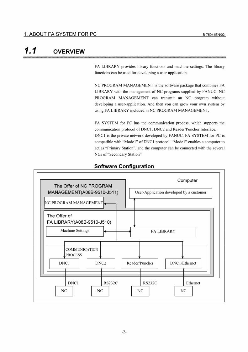
FA LIBRARY provides library functions and machine settings. The library
functions can be used for developing a user-application.
NC PROGRAM MANAGEMENT is the software package that combines FA
LIBRARY with the management of NC programs supplied by FANUC. NC
PROGRAM MANAGEMENT can transmit an NC program without
developing a user-application. And then you can grow your own system by
using FA LIBRARY included in NC PROGRAM MANAGEMENT.
FA SYSTEM for PC has the communication process, which supports the
communication protocol of DNC1, DNC2 and Reader/Puncher Interface.
DNC1 is the private network developed by FANUC. FA SYSTEM for PC is
compatible with “Mode1” of DNC1 protocol. “Mode1” enables a computer to
act as “Primary Station”, and the computer can be connected with the several
NCs of “Secondary Station”.
Software Configuration
COMMUNICATION
PROCESS
The Offer of NC PROGRAM
MANAGEMENT(A08B-9510-J511)
NC PROGRAM MANAGEMENT
User-Application developed by a customer
The Offer of
FA LIBRARY(A08B-9510-J510)
FA LIBRARY
�
DNC1 DNC2 Reader/Puncher
NC NC NC
DNC1 RS232C RS232C
Computer
Machine Settings
DNC1/Ethernet
NC
Ethernet
B-75044EN/02 1. ABOUT FA SYSTEM FOR PC
-3-
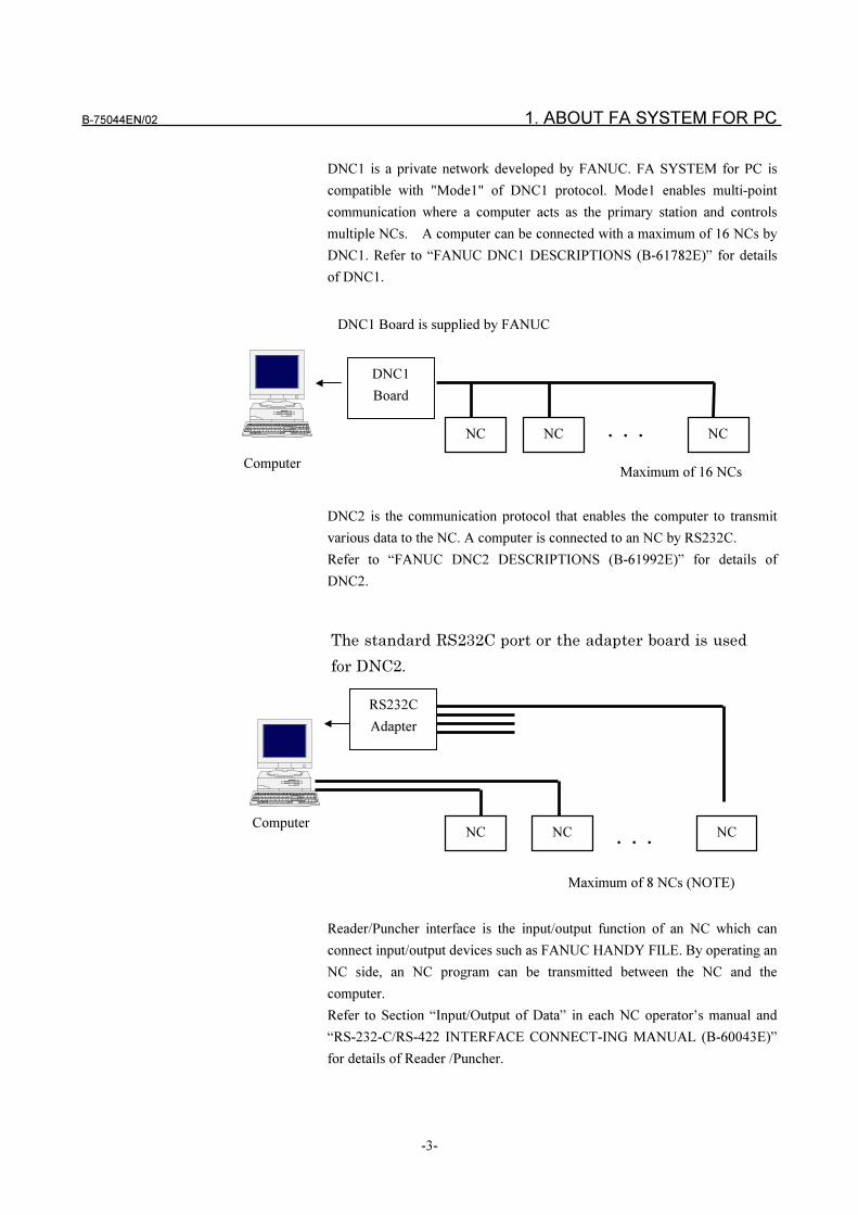
DNC1 is a private network developed by FANUC. FA SYSTEM for PC is
compatible with "Mode1" of DNC1 protocol. Mode1 enables multi-point
communication where a computer acts as the primary station and controls
multiple NCs. A computer can be connected with a maximum of 16 NCs by
DNC1. Refer to “FANUC DNC1 DESCRIPTIONS (B-61782E)” for details
of DNC1.
DNC2 is the communication protocol that enables the computer to transmit
various data to the NC. A computer is connected to an NC by RS232C.
Refer to “FANUC DNC2 DESCRIPTIONS (B-61992E)” for details of
DNC2.
Reader/Puncher interface is the input/output function of an NC which can
connect input/output devices such as FANUC HANDY FILE. By operating an
NC side, an NC program can be transmitted between the NC and the
computer.
Refer to Section “Input/Output of Data” in each NC operator’s manual and
“RS-232-C/RS-422 INTERFACE CONNECT-ING MANUAL (B-60043E)”
for details of Reader /Puncher.
RS232C
Adapter
The standard RS232C port or the adapter board is used
for DNC2.
ComputerNCNC
����NC
Maximum of 8 NCs (NOTE)
Computer
DNC1
Board
NCNC ����
Maximum of 16 NCs
NC
DNC1 Board is supplied by FANUC
1. ABOUT FA SYSTEM FOR PC B-75044EN/02
-4-
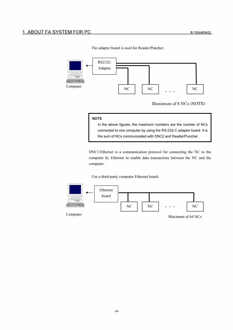
DNC1/Ethernet is a communication protocol for connecting the NC to the
computer by Ethernet to enable data transactions between the NC and the
computer.
RS232C
Adapter
The adapter board is used for Reader/Puncher.
ComputerNCNC
����NC
Maximum of 8 NCs (NOTE)
Computer
Ethernet
board
NCNC ����
Maximum of 64 NCs
NC
Use a third-party computer Ethernet board.
NOTE
In the above figures, the maximum numbers are the number of NCs
connected to one computer by using the RS-232-C adapter board. It is
the sum of NCs communicated with DNC2 and Reader/Puncher.
B-75044EN/02 1. ABOUT FA SYSTEM FOR PC
-5-
1.2 RELATION BETWEEN FA SYSTEM FOR PC AND PROTOCOLS
FA SYSTEM for PC supports the protocols of DNC1, DNC2,
Reader/Puncher and DNC1/Ethernet. And the available functions of NC
PROGRAM MANAGEMENT and FA LIBRARY depend upon the capability
of each protocol as follows.
Functions of FA LIBRARY (A08B-9510-J510)
A user-application developed by using FA LIBRARY can take the functions
like these:
(1) For DNC1 or DNC2
� Downloading an NC program to an NC.
� Uploading an NC program from an NC
� External reset
� Selecting and deleting an NC program saved in an NC
� Listing NC programs saved in an NC
� Reading the alarm information in an NC
� Reading and writing the tool offset data
� Reading and writing the custom macro variables
� Reading the tool life data
� Reading and writing PMC data
� Reading the system identify of an NC
� Informs the start and completion of download required by NC
� Informs the start and completion of upload required by NC
(2) For Reader/Puncher protocol:
� Informs the start and completion of download required by NC
� Informs the start and completion of upload required by NC
(3) For DNC1/Ethernet
� Downloading an NC program to an NC
� Uploading an NC program from an NC
� DNC operation
� Selecting and deleting an NC program saved in an NC
� Reading the NC directory information
� Reading the alarm information in an NC
� Reading and writing the custom macro variables
� Reading and writing the tool life data (scheduled to be supported)
� Reading and writing PMC data
� Reading the system identify of an NC
� Reading and writing NC parameters
1. ABOUT FA SYSTEM FOR PC B-75044EN/02
-6-
Functions of NC PROGRAM MANAGEMENT (A08B-9510-J511)
(1) For DNC1 or DNC2
NC PROGRAM MANAGEMENT can handle the following functions by
operating a computer.
� A computer can download an NC program to an NC memory.
� A computer can upload an NC program from an NC memory.
� NC PROGRAM MANAGEMENT can display the list of NC
programs saved in the NC memory.
� NC PROGRAM MANAGEMENT can delete the NC program
saved in the NC memory.
The following functions can be handled by operating the CRT/MDI on
an NC.
� An NC can read an NC program from a computer.
� An NC can punch an NC program to a computer.
� An NC can call an NC program saved in a computer for DNC
operation.
(2) For Reader/Puncher
The following functions can be handled by operating the CRT/MDI on
an NC.
� An NC can read an NC program from a computer.
� An NC can punch an NC program to a computer.
� An NC can display the list of NC programs saved in a computer.
� An NC can delete an NC program saved in a computer.
� An NC can call an NC program saved in a computer for DNC
operation.
(3) For DNC1/Ethernet
NC PROGRAM MANAGEMENT can handle the following functions by
operating a computer:
� A computer can download an NC program to NC memory.
� A computer can upload an NC program from NC memory.
� NC PROGRAM MANAGEMENT can display the list of NC
programs saved in the NC memory.
� NC PROGRAM MANAGEMENT can delete the NC program
saved in NC memory.
NOTE
When you uses the Reader/Puncher for some old types of NCs, it is
impossible to use several above functions, or it is necessary to add NC
optional parameters.
NOTE
DNC1/Ethernet communication does not allow download or upload by
CRT/MDI operations on the NC. (scheduled to be supported)
B-75044EN/02 1. ABOUT FA SYSTEM FOR PC
-7-
1.3 TRANSMITTING NC PROGRAM
A main feature of FA SYSTEM for PC is its ability to transmit an NC
program. This section describes the way to transmit an NC program of NC
PROGRAM MANAGEMENT and FA LIBRARY.
1.3.1 Transmitting by Operating NC PROGRAM MANAGEMENT
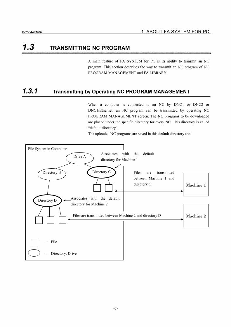
When a computer is connected to an NC by DNC1 or DNC2 or
DNC1/Ethernet, an NC program can be transmitted by operating NC
PROGRAM MANAGEMENT screen. The NC programs to be downloaded
are placed under the specific directory for every NC. This directory is called
“default-directory”.
The uploaded NC programs are saved in this default-directory too.
Machine 1
Machine 2
File System in Computer
� File
� Directory, Drive
Associates with the default
directory for Machine 2
Files are transmitted between Machine 2 and directory D
Associates with the default
directory for Machine 1
Files are transmitted
between Machine 1 and
directory C
Directory B
Drive A
Directory C
Directory D
1. ABOUT FA SYSTEM FOR PC B-75044EN/02
-8-
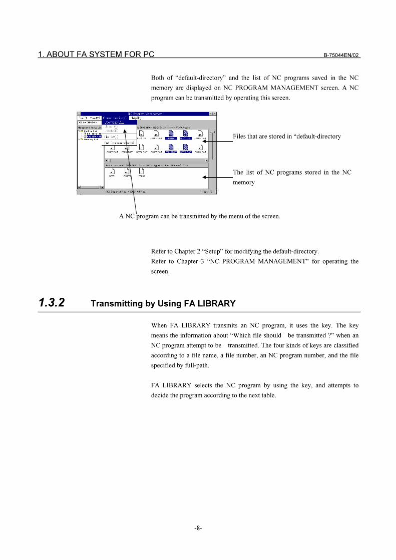
Both of “default-directory” and the list of NC programs saved in the NC
memory are displayed on NC PROGRAM MANAGEMENT screen. A NC
program can be transmitted by operating this screen.
A NC program can be transmitted by the menu of the screen.
Files that are stored in “default-directory
The list of NC programs stored in the NC
memory
Refer to Chapter 2 “Setup” for modifying the default-directory.
Refer to Chapter 3 “NC PROGRAM MANAGEMENT” for operating the
screen.
1.3.2 Transmitting by Using FA LIBRARY
When FA LIBRARY transmits an NC program, it uses the key. The key
means the information about “Which file should be transmitted ?” when an
NC program attempt to be transmitted. The four kinds of keys are classified
according to a file name, a file number, an NC program number, and the file
specified by full-path.
FA LIBRARY selects the NC program by using the key, and attempts to
decide the program according to the next table.
B-75044EN/02 1. ABOUT FA SYSTEM FOR PC
-9-
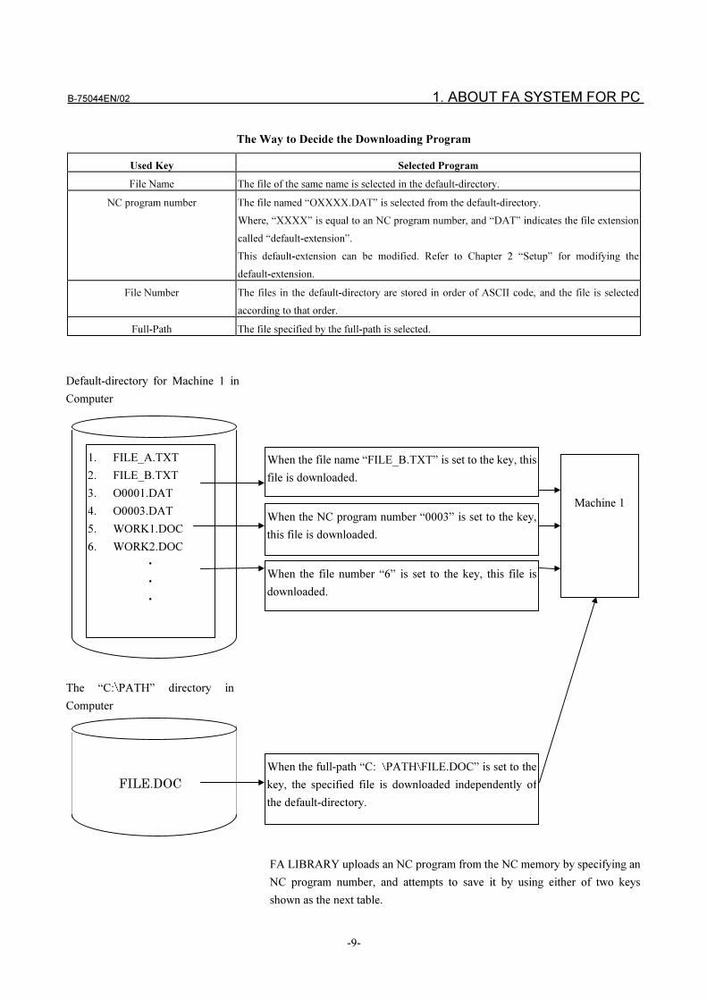
The Way to Decide the Downloading Program
Used Key Selected Program
File Name The file of the same name is selected in the default-directory.
NC program number The file named “OXXXX.DAT” is selected from the default-directory.
Where, “XXXX” is equal to an NC program number, and “DAT” indicates the file extension
called “default-extension”.
This default-extension can be modified. Refer to Chapter 2 “Setup” for modifying the
default-extension.
File Number The files in the default-directory are stored in order of ASCII code, and the file is selected
according to that order.
Full-Path The file specified by the full-path is selected.
FA LIBRARY uploads an NC program from the NC memory by specifying an
NC program number, and attempts to save it by using either of two keys
shown as the next table.
1. FILE_A.TXT
2. FILE_B.TXT
3. O0001.DAT
4. O0003.DAT
5. WORK1.DOC
6. WORK2.DOC
�
�
�
When the file name “FILE_B.TXT” is set to the key, this
file is downloaded.
When the NC program number “0003” is set to the key,
this file is downloaded.
When the file number “6” is set to the key, this file is
downloaded.
Default-directory for Machine 1 in
Computer
Machine 1
FILE.DOC
The “C: PATH” directory in
Computer
When the full-path “C: PATH FILE.DOC” is set to the
key, the specified file is downloaded independently of
the default-directory.
1. ABOUT FA SYSTEM FOR PC B-75044EN/02
-10-
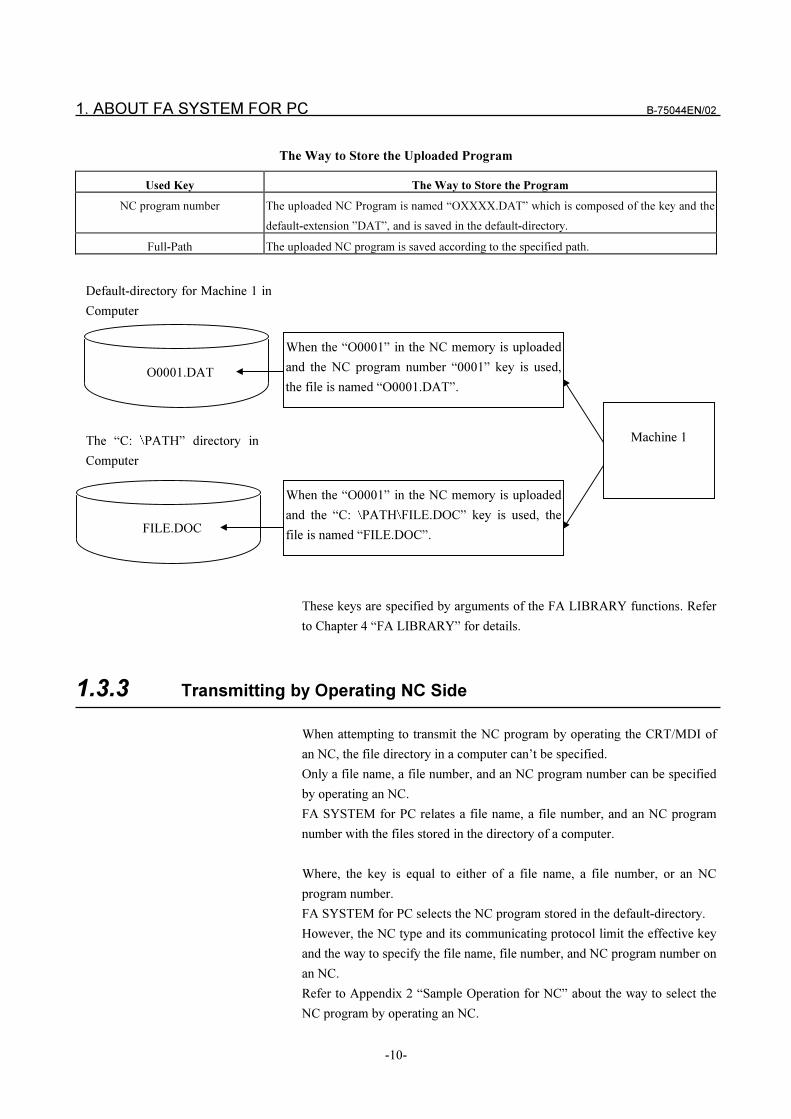
The Way to Store the Uploaded Program
Used Key The Way to Store the Program
NC program number The uploaded NC Program is named “OXXXX.DAT” which is composed of the key and the
default-extension ”DAT”, and is saved in the default-directory.
Full-Path The uploaded NC program is saved according to the specified path.
These keys are specified by arguments of the FA LIBRARY functions. Refer
to Chapter 4 “FA LIBRARY” for details.
1.3.3 Transmitting by Operating NC Side
When attempting to transmit the NC program by operating the CRT/MDI of
an NC, the file directory in a computer can’t be specified.
Only a file name, a file number, and an NC program number can be specified
by operating an NC.
FA SYSTEM for PC relates a file name, a file number, and an NC program
number with the files stored in the directory of a computer.
Where, the key is equal to either of a file name, a file number, or an NC
program number.
FA SYSTEM for PC selects the NC program stored in the default-directory.
However, the NC type and its communicating protocol limit the effective key
and the way to specify the file name, file number, and NC program number on
an NC.
Refer to Appendix 2 “Sample Operation for NC” about the way to select the
NC program by operating an NC.
O0001.DAT
When the “O0001” in the NC memory is uploaded
and the NC program number “0001” key is used,
the file is named “O0001.DAT”.
Default-directory for Machine 1 in
Computer
Machine 1
When the “O0001” in the NC memory is uploaded
and the “C: PATH FILE.DOC” key is used, the
file is named “FILE.DOC”.FILE.DOC
The “C: PATH” directory in
Computer
B-75044EN/02 1. ABOUT FA SYSTEM FOR PC
-11-
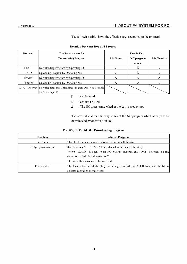
The following table shows the effective keys according to the protocol.
Relation between Key and Protocol
Protocol The Requirement for Usable Key
Transmitting Program File Name NC program
number
File Number
DNC1, Downloading Program by Operating NC ��
�
DNC2 Uploading Program by Operating NC ��
�
Reader/ Downloading Program by Operating NC ∆ � ∆
Puncher Uploading Program by Operating NC ∆ ∆ �
DNC1/Ethernet Downloading and Uploading Program Are Not Possible
by Operating NC
� : can be used
� : can not be used
∆ : The NC types cause whether the key is used or not.
The next table shows the way to select the NC program which attempt to be
downloaded by operating an NC .
The Way to Decide the Downloading Program
Used Key Selected Program
File Name The file of the same name is selected in the default-directory.
NC program number the file named “OXXXX.DAT” is selected in the default-directory.
Where, “XXXX” is equal to an NC program number, and “DAT” indicates the file
extension called “default-extension”.
This default-extension can be modified.
File Number The files in the default-directory are arranged in order of ASCII code, and the file is
selected according to that order.
1. ABOUT FA SYSTEM FOR PC B-75044EN/02
-12-
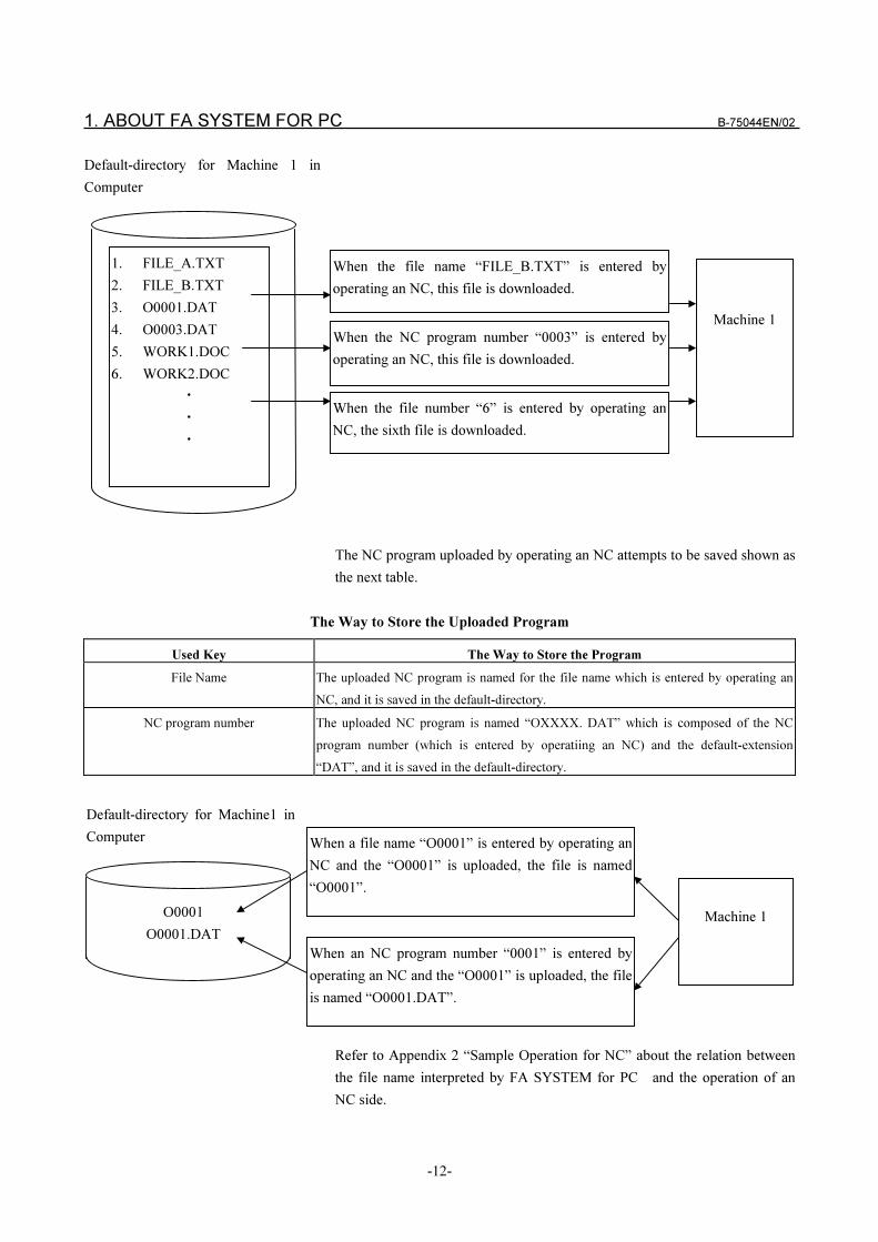
The NC program uploaded by operating an NC attempts to be saved shown as
the next table.
The Way to Store the Uploaded Program
Used Key The Way to Store the Program
File Name The uploaded NC program is named for the file name which is entered by operating an
NC, and it is saved in the default-directory.
NC program number The uploaded NC program is named “OXXXX. DAT” which is composed of the NC
program number (which is entered by operatiing an NC) and the default-extension
“DAT”, and it is saved in the default-directory.
Refer to Appendix 2 “Sample Operation for NC” about the relation between
the file name interpreted by FA SYSTEM for PC and the operation of an
NC side.
O0001
O0001.DAT
When a file name “O0001” is entered by operating an
NC and the “O0001” is uploaded, the file is named
“O0001”.
When the file name “FILE_B.TXT” is entered by
operating an NC, this file is downloaded.
Default-directory for Machine1 in
Computer
When the NC program number “0003” is entered by
operating an NC, this file is downloaded.
Machine 1
When the file number “6” is entered by operating an
NC, the sixth file is downloaded.
When an NC program number “0001” is entered by
operating an NC and the “O0001” is uploaded, the file
is named “O0001.DAT”.
Machine 1
1. FILE_A.TXT
2. FILE_B.TXT
3. O0001.DAT
4. O0003.DAT
5. WORK1.DOC
6. WORK2.DOC
�
�
�
Default-directory for Machine 1 in
Computer
B-75044EN/02 1. ABOUT FA SYSTEM FOR PC
-13-
1.4 ABOUT NC PROGRAM FORMAT
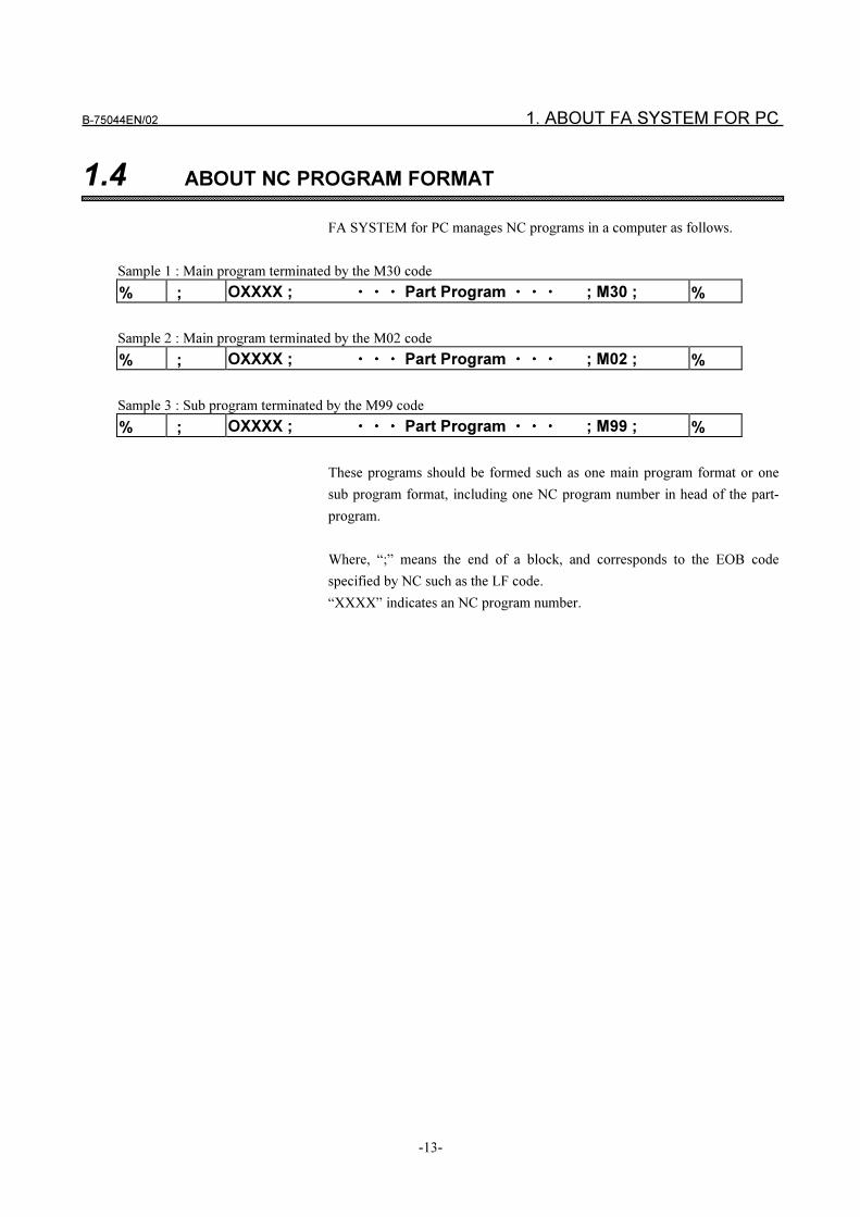
FA SYSTEM for PC manages NC programs in a computer as follows.
Sample 1 : Main program terminated by the M30 code
% ; OXXXX ; ���� ���� ���� Part Program ���� ���� ���� ; M30 ; %
Sample 2 : Main program terminated by the M02 code
% ; OXXXX ; ���� ���� ���� Part Program ���� ���� ���� ; M02 ; %
Sample 3 : Sub program terminated by the M99 code
% ; OXXXX ; ���� ���� ���� Part Program ���� ���� ���� ; M99 ; %
These programs should be formed such as one main program format or one
sub program format, including one NC program number in head of the part-
program.
Where, “;” means the end of a block, and corresponds to the EOB code
specified by NC such as the LF code.
“XXXX” indicates an NC program number.
1. ABOUT FA SYSTEM FOR PC B-75044EN/02
-14-
1.5 SUBPROGRAM TRANSFER FUNCTION
What Is The Subprogram Transfer Function?
The “subprogram transfer function” downloads the subprogram together with
the NC program if the NC program contains a subprogram call when the NC
program is downloaded.
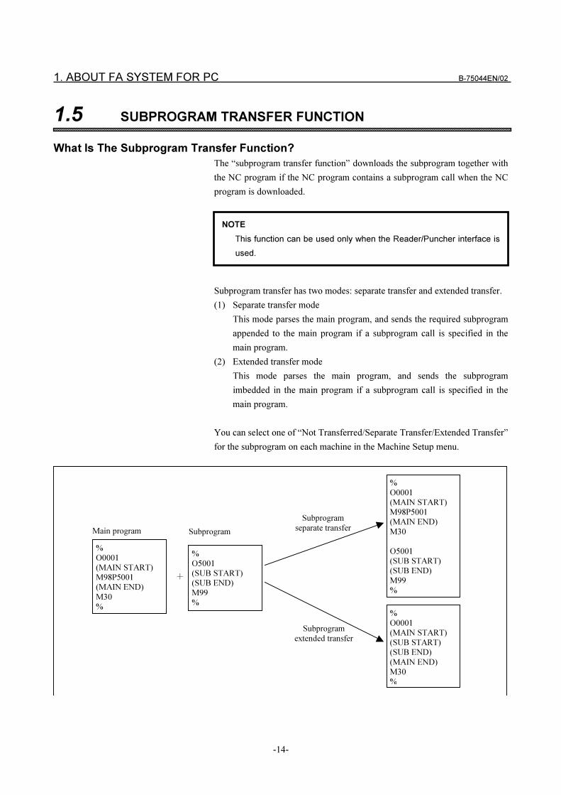
Subprogram transfer has two modes: separate transfer and extended transfer.
(1) Separate transfer mode
This mode parses the main program, and sends the required subprogram
appended to the main program if a subprogram call is specified in the
main program.
(2) Extended transfer mode
This mode parses the main program, and sends the subprogram
imbedded in the main program if a subprogram call is specified in the
main program.
You can select one of “Not Transferred/Separate Transfer/Extended Transfer”
for the subprogram on each machine in the Machine Setup menu.
NOTE
This function can be used only when the Reader/Puncher interface is
used.
%
O0001
(MAIN START)
M98P5001
(MAIN END)
M30
%
%
O5001
(SUB START)
(SUB END)
M99
%
�
%
O0001
(MAIN START)
(SUB START)
(SUB END)
(MAIN END)
M30
%
%
O0001
(MAIN START)
M98P5001
(MAIN END)
M30
O5001
(SUB START)
(SUB END)
M99
%
Subprogram
separate transfer
Subprogram
extended transfer
Main program Subprogram
B-75044EN/02 1. ABOUT FA SYSTEM FOR PC
-15-
Subprogram File Names
Subprogram file names must be specified in the following format:
“O” + 4-digit number + “.” + 3-letter extension
Example: O0001.DAT
Register the extension in the [Subprogram Extension] in the [General] panel
in the Machine Setup menu.
Subprogram File Format
Only one O number and M99 code each are both required in the subprogram
file. See Example 3 in “1.4 About NC Program Format.”
Subprogram files containing repeated O numbers and M99 codes cannot be
sent. Calling a subprogram containing an M02 or M30 code instead of an
M99 code will result in an error.
Subprogram File Directory
Up to three directories for storing subprogram files can be set in the
[Subprogram Search Directory 1 to 3] in the [Download] panel in the
Machine Setup menu. The subprogram search order of priority is set to the
three directories. For example, if the No.1 directory and No.2 directory hold a
program having the same name, the subprogram in the No.1 directory is sent.
Subprogram Non-call Setting
You can disable subprogram transfer even if a subprogram is called by the
main program. For example, you can set “Not to send subprograms in lines
8000 to 9000 as they are stored in NC memory.” You can set this in 1000-line
units in the [Subprograms Not To Send] in the [Download] panel in the
Machine Setup menu.
Subprogram Call Code Setting
You can set the call code by which the subprogram is sent. Call types M98,
G65 and G66 are supported, and subprogram transfer is carried out only for
the call type you have set.
Set the call code in the [Call Type] in the [Download] panel in the Machine
Setup menu.
NOTE
Subprograms are searched only from the directories set in the
[Subprogram Search Directory 1 to 3]. To store a subprogram in the
default directory, specify the same directory as the default directory
somewhere in the [Subprogram Search Directory 1 to 3].
1. ABOUT FA SYSTEM FOR PC B-75044EN/02
-16-
1.5.1 Details of Subprogram Separate Transfer Function
Subprogram Call Formats
The following four subprogram call formats can be used in the main program:
(1) M98PxxxxLyy
(2) M98Pyyxxxx
(3) G65PxxxxLyy
(4) G66PxxxxLyy
where,
xxxx: program number
yy: call repeat count (This can be omitted.)
In the case of format (2), a 4-digit number is needed for the program number.
Note, however, that in the separate transfer mode subprograms that are called
more than once due to the relationship between the main and subprograms are
transferred only once. So, the call repeat count is ignored.
The subprogram call nesting level is 8.
If the control discovers that the currently called subprogram does not exist in
the main program, an error occurs when an attempt is made to send the non-
existent subprogram after the main program is sent.
NOTE
1 Program numbers xxxx are limited to numbers that can be directly
specified. Program numbers that are specified by macro variables
cannot be transferred.
2 "M99Pnnnn" (return function to sequence number) cannot be used. At
the point that the subprogram up to the line containing the M99
instruction is read, the system judges that the subprogram has ended
and returns to the main program. The Pnnnn section is ignored.
3 Branch instructions (GOTO, IF, WHILE) are transferred to the NC
without being processed.
B-75044EN/02 1. ABOUT FA SYSTEM FOR PC
-17-
1.5.2 Details of Subprogram Extended Transfer Function
Subprogram Call Formats
The following four subprogram call formats can be used in the main program:
(1) M98PxxxxLyy
(2) M98Pyyxxxx
(3) G65PxxxxLyy
(4) G66PxxxxLyy
where,
xxxx: program number
yy: call repeat count (This can be omitted.)
In the case of format (2), a 4-digit number is needed for the program number.
In extended transfer, subprograms that are called more than once due to the
relationship between the main and subprograms are sent imbedded in the main
program for the repeated call count.
The subprogram call nesting level is 8.
If the control discovers that the preset directory does not contain the
subprogram currently being called by the main program, an error occurs
immediately. So, transfer of the main program is canceled midway, and the
subprogram is not sent.
NOTE
1 Program numbers xxxx are limited to numbers that can be directly
specified. Program numbers that are specified by macro variables
cannot be transferred.
2 "M99Pnnnn" (return function to sequence number) cannot be used. At
the point that the subprogram up to the line containing the M99
instruction is read, the system judges that the subprogram has ended
and returns to the main program. The Pnnnn section is ignored.
3 Branch instructions (GOTO, IF, WHILE) are transferred to the NC
without being processed.
4 When transferring in the extended transfer mode, only subprograms
cannot be transferred. If only a subprogram is transferred, the "Main
program contains M99." error is generated.
5 Other addresses cannot be specified for the blocks that call the
subprogram:
Example: When the block "M98P9000G00X00Y00" is sent in the
extended transfer mode, the contents of subprogram O9000.DAT can
be sent. However, the G00X00Y00 part cannot be sent.
1. ABOUT FA SYSTEM FOR PC B-75044EN/02
-18-
1.6 LIST FILE TRANSFER FUNCTION
What Is The "List File Transfer Function?"
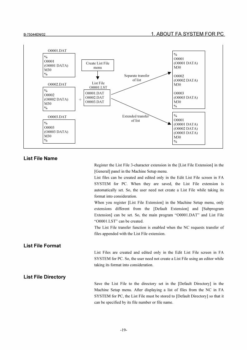
The “List File transfer function” sends two or more NC programs described in
the “List File” to the NC.
Create the List File in the Edit List File screen in FA SYSTEM for PC.
Up to 9999 NC programs can be registered to the List File.
The List File transfer has two modes: separate transfer and extended transfer.
� List separate transfer mode
This mode sends NC programs currently registered to List File in order
as they are. This mode assumes that you are registering two or more main
programs to the NC memory.
� List extended transfer mode
This mode deletes the O number and M30 code from the NC programs
currently registered to List File and sends the NC programs as a single
NC program. This mode assumes that two or more NC programs are
linked into a single program for DNC operation.
You can select either of separate transfer or extended transfer for transferring
the List File on each machine in the Machine Setup menu.
NOTE
This function can be used only when the Reader/Puncher interface is
used.
B-75044EN/02 1. ABOUT FA SYSTEM FOR PC
-19-
List File Name
Register the List File 3-character extension in the [List File Extension] in the
[General] panel in the Machine Setup menu.
List files can be created and edited only in the Edit List File screen in FA
SYSTEM for PC. When they are saved, the List File extension is
automatically set. So, the user need not create a List File while taking its
format into consideration.
When you register [List File Extension] in the Machine Setup menu, only
extensions different from the [Default Extension] and [Subprogram
Extension] can be set. So, the main program “O0001.DAT” and List File
“O0001.LST” can be created.
The List File transfer function is enabled when the NC requests transfer of
files appended with the List File extension.
List File Format
List Files are created and edited only in the Edit List File screen in FA
SYSTEM for PC. So, the user need not create a List File using an editor while
taking its format into consideration.
List File Directory
Save the List File to the directory set in the [Default Directory] in the
Machine Setup menu. After displaying a list of files from the NC in FA
SYSTEM for PC, the List File must be stored to [Default Directory] so that it
can be specified by its file number or file name.
%
O0001
(O0001 DATA)
M30
%
�
%
O0001
(O0001 DATA)
(O0002 DATA)
(O0003 DATA)
M30
%
%
O0001
(O0001 DATA)
M30
O0002
(O0002 DATA)
M30
O0003
(O0003 DATA)
M30
%
Separate transfer
of list
Extended transfer
of list
O0001.DAT
List File
O0001.LST%
O0002
(O0002 DATA)
M30
%
%
O0003
(O0003 DATA)
M30
%
O0001.DAT
O0002.DAT
O0003.DAT
O0002.DAT
O0003.DAT
Create List File
menu
1. ABOUT FA SYSTEM FOR PC B-75044EN/02
-20-
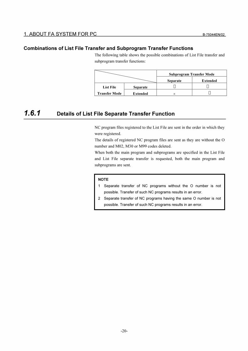
Combinations of List File Transfer and Subprogram Transfer Functions
The following table shows the possible combinations of List File transfer and
subprogram transfer functions:
Subprogram Transfer Mode
Separate Extended
Separate � �List File
Transfer Mode Extended ��
1.6.1 Details of List File Separate Transfer Function
NC program files registered to the List File are sent in the order in which they
were registered.
The details of registered NC program files are sent as they are without the O
number and M02, M30 or M99 codes deleted.
When both the main program and subprograms are specified in the List File
and List File separate transfer is requested, both the main program and
subprograms are sent.
NOTE
1 Separate transfer of NC programs without the O number is not
possible. Transfer of such NC programs results in an error.
2 Separate transfer of NC programs having the same O number is not
possible. Transfer of such NC programs results in an error.
B-75044EN/02 1. ABOUT FA SYSTEM FOR PC
-21-
1.6.2 Details of List File Extended Transfer Function
Two or more main programs registered to the List File are sent linked as they
were a single NC program.
The O number and M30 or M02 codes in the registered NC program files are
not sent.
The O number that is sent at the start of extended transfer can be specified by
the following two ways in the Edit File List screen:
(1) The O number of the first NC program registered to the List File is sent.
(2) The O number specified in the [Specify O Number at Extended Transfer]
in the Edit List File screen is sent.
Though extended transfer of NC programs without the O number is possible,
the O number must be specified according to (2) above.
Send the M30 code at the end of extended transfer.
1.6.3 List File Transfer Monitor and Control Functions
When the List File Monitor screen is used, the transfer monitor is displayed.
This allows to control such as pause, skipping transfer and swapping of the
transfer order for NC programs that are in the List File and that have not yet
been sent.
List File Transfer Monitor Display
During List File transfer, you can display which NC programs have not yet
been sent.
This assumes that you know how far transfer has progressed when you are
sending two or more main programs by extended transfer for DNC operation.
NOTE
1 Extended transfer of the main program and subprograms specified in
the List File is not possible. When this is attempted, the M02 or M30
codes in the main program will be deleted. However, the M99 code in
the subprogram will be sent without being deleted.
2 Extended transfer of NC programs having the same O number is not
possible. Transfer of such NC programs results in an error.
1. ABOUT FA SYSTEM FOR PC B-75044EN/02
-22-
List File Transfer Control Function
During List File transfer, you can carry out the following controls on NC
programs that have not yet been sent:
(1) Pause
Pauses transfer before the specified NC program is sent. The transfer
order of NC programs registered after the paused NC program can be
changed, programs deleted and new programs added.
(2) Skip
Sends the next currently registered NC program without sending the
specified NC program.
(3) Change order
You can change the transfer order.
(4) Delete and add NC programs.
You can delete NC programs registered after the paused NC program or
add new NC programs.
NOTE
1 To use this function, check the [Wait for send buffer to reach 0 before
proceeding to next record in extended transfer mode] check box in the
[Download] panel in the Machine Setup menu.
2 When you actually send data, transfer is influenced by your computer's
send buffer and your NC's receive buffer; so the details displayed on
the monitor screen may not match the details displayed on the NC
screen. For example, the NC program displayed as currently being
sent on the monitor screen may not yet be received on the NC.
NC programs among those registered to the List File that have not yet
started to be sent can be displayed correctly.
NOTE
The List File created in the Edit List File screen is copied to each NC
as the List File to be is browsed when the List File is sent to the NC.
The List File is copied to each NC before transfer is started. The
details currently displayed and edited in the List File Monitor screen is
the List File copied to each NC.
For this reason, details that are paused, order-changed, deleted or
added in the List File Monitor screen are partial changes that are valid
only during List File transfer.
Changes that are always reflected at each transfer must be made in
the Edit List File screen before you transmit the List File.

B-75044EN/02 2. SETUP
-23-
2 SETUP
2. SETUP B-75044EN/02
-24-
2.1 SYSTEM REQUIREMENTS
Your system must suit the following minimum requirements in order to run
FA SYSTEM for PC.
(1) Body of Computer
� Type of PC: PC/AT compatible machine
� CPU: Pentium (75MHz) or higher recommended
� Memory: 32MB RAM or more recommended
� Floppy Disk: one 3.5 inch 1.44MB Drive
� Hard Disk: 85MB Hard Disk or larger recommended
(2) Display
� Resolution: 1024�768 dot or higher recommended
� Color: 16 colors or more
(3) Operating System
� Microsoft Windows NT4.0
+ Windows NT4.0 Service Pack 3
(4) Developing Environment
(You needs the following software tools when you program a user-
application by using FA LIBRARY.)
� Microsoft Visual Basic 5.0 (from here on referred to as VB)
+ Visual Studio97 Service Pack 3 (from here on reffered to as
VB++) or
� Microsoft C++ 5.0
+Visual Studio97 Service pack 3 (from here on referred to as
VC++)
(5) Keyboard
(6) Mouse
(7) DNC1 Board and Software Driver
(In the case that your system uses DNC1 communication)
� Supplied by FANUC: A20B-8100-0070
B-75044EN/02 2. SETUP
-25-
(8) RS-232-C Communication Board
(In the case that your system uses DNC2 or Reader/Puncher)
Use the following boards made by Digi International as the RS-232-C
communication boards:
� AccelePort 4r-ISA (for 4 ports, DTE/DB25 male)
� AccelePort 8r-ISA (for 8 ports, DTE/DB25 male)
When DNC2 is used, the DNC2 board and option are needed on the NC.
The option is needed on the NC when the Reader/Puncher is to be used.
(9) Purchase a third-party Ethernet board (when DNC1/Ethernet is used).
The Ethernet board and option are needed on the NC. (The Ethernet
board for the NC is the 10BASE-T interface.)
NOTE
WindowsNT 4.0 does not have a PnP (plug-and-play) function. When
the DNC1 board is to be used, set the PnP function OFF in the BIOS
settings. The method for setting BIOS varies according to the
computer. Refer to the Operator's Manual for your computer.
2. SETUP B-75044EN/02
-26-
2.2 DNC1
The DNC1 board must be installed according to the next procedure.
DNC1 Board Installation
Please insert the DNC1 board into your computer.
For more information about installing the DNC1 board, refer to “D.1 System
Requirements for Installing DNC1 Board”, “D.2 Condition of using DNC1
Driver” and “D.3 Setting DNC1 Board”.
DNC1 Driver Installation
Please install the DNC1 software to your computer with the floppy disk
labeled “DNC1 Driver Disk Setup”.
Refer to “D.4 DNC1 Driver Settings” for details of the software installation.
Testing DNC1 Board
After the completion of the DNC1 board and DNC1 driver installation, please
join the loop-back test connector (A13B-0156-C201) to the terminating
resister unit, start the “Dnc1HardTest” software, and check whether the DNC1
board and software driver are installed correctly or not.
Refer to “D.5 Dnc1HardTest” for details of test.
B-75044EN/02 2. SETUP
-27-
2.3 DNC2, READER/PUNCHER
When a computer communicates to NCs with DNC2 or Reader/Puncher, RS-
232-C ports are used.
Setting a RS232C Adapter Board
The RS-232-C adapter boards described in item(8) of “2.1. System
Requirements” can be used.
When using the RS-232-C adapter board, you must install the adapter
according to its manual.
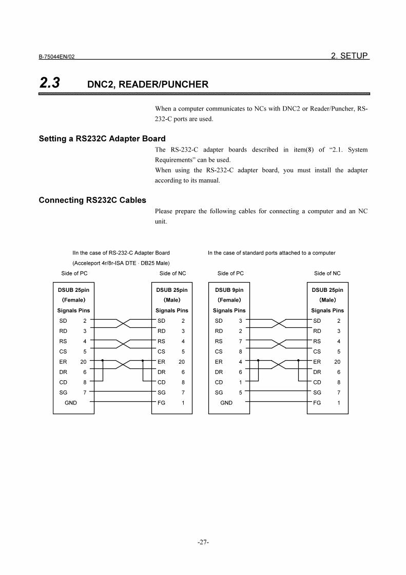
Connecting RS232C Cables
Please prepare the following cables for connecting a computer and an NC
unit.
IIn the case of RS-232-C Adapter Board In the case of standard ports attached to a computer
(Acceleport 4r/8r-ISA DTE � DB25 Male)
Side of PC Side of NC Side of PC Side of NC
DSUB 9pin
����Female����
Signals Pins
SD 3
RD 2
RS 7
CS 8
ER 4
DR 6
CD 1
SG 5
GND
DSUB 25pin
����Male����
Signals Pins
SD 2
RD 3
RS 4
CS 5
ER 20
DR 6
CD 8
SG 7
FG 1
DSUB 25pin
����Female����
Signals Pins
SD 2
RD 3
RS 4
CS 5
ER 20
DR 6
CD 8
SG 7
GND
DSUB 25pin
����Male����
Signals Pins
SD 2
RD 3
RS 4
CS 5
ER 20
DR 6
CD 8
SG 7
FG 1
2. SETUP B-75044EN/02
-28-
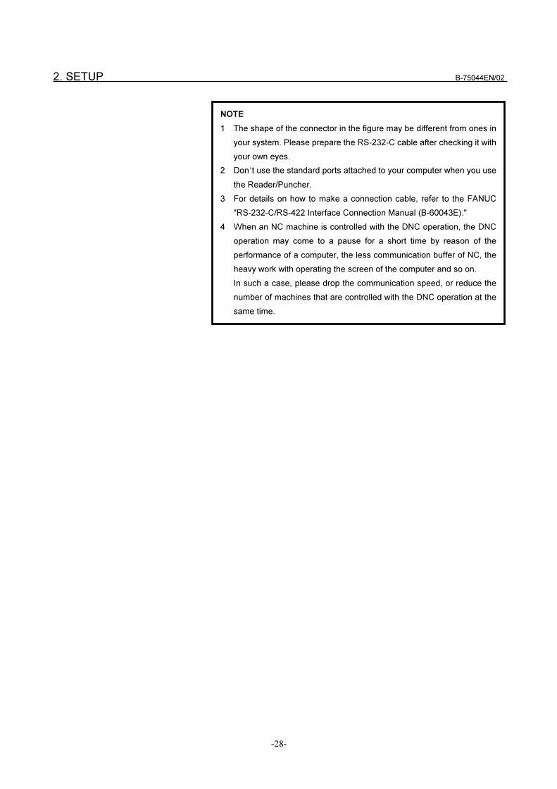
NOTE
1 The shape of the connector in the figure may be different from ones in
your system. Please prepare the RS-232-C cable after checking it with
your own eyes.
2 Don’t use the standard ports attached to your computer when you use
the Reader/Puncher.
3 For details on how to make a connection cable, refer to the FANUC
"RS-232-C/RS-422 Interface Connection Manual (B-60043E)."
4 When an NC machine is controlled with the DNC operation, the DNC
operation may come to a pause for a short time by reason of the
performance of a computer, the less communication buffer of NC, the
heavy work with operating the screen of the computer and so on.
In such a case, please drop the communication speed, or reduce the
number of machines that are controlled with the DNC operation at the
same time.
B-75044EN/02 2. SETUP
-29-
2.4 SETTING FA SYSTEM FOR PC
2.4.1 Setting up TCP/IP
FA SYSTEM for PC utilizes the TCP/IP (Transmission Control
Protocol/Internet Protocol) network protocol even if the computer is not
connected with a network. Therefore, the TCP/IP protocol service must be
added to WindowsNT before FA SYSTEM for PC installation.
To know whether TCP/IP is installed in WindowsNT or not, please double-
click the “Network” program in the “Control Panel” group box. The “TCP/IP
Protocol” item can be found in the “Installed Network Software” list box
when WindowsNT contains the TCP/IP protocol.
If TCP/IP protocol isn’t installed, it must be installed by using the “Network”
software of the “Control Panel” group box. Refer to the setup guide of
WindowsNT for the installation.
Normally, the Ethernet board is needed when you install TCP/IP protocol
services. When you install FA SYSTEM for PC on a computer that does not
have an Ethernet board, select “MS Loopback Adapter” provided by
Microsoft as the network adapter, and then install TCP/IP protocol services.
Confirming localhost
“localhost” is a special host name that indicates the self node in TCP/IP
protocol. When WindowsNT is installed, localhost is automatically registered.
However, FA SYSTEM for PC cannot be started normally if this setting is
deleted.
Before you install FA SYSTEM for PC, make sure that localhost is registered
to the hosts file.
The host file will be at the following directory assuming that “c: winnt” is the
directory in which WindowsNT is set up. (The directory in which the
WindowsNT is set up is registered to system setup variable “windir” after
[System] in the [Control Panel] is started.)
“c: winn system32 drivers etc hosts”
NOTE
Setting up TCP/IP in "2.4.1 Setting Up TCP/IP" and installing FA
SYSTEM for PC in "2.4.3 For Setting FA SYSTEM for PC" must be
carried out by a user having administrator privileges.
2. SETUP B-75044EN/02
-30-
Open this file using the Note Pad or other editor, and make cure that the
following line is described in the file. (Normally, this line is located near the
top of the file.)
Add this line if it is not described in the file.
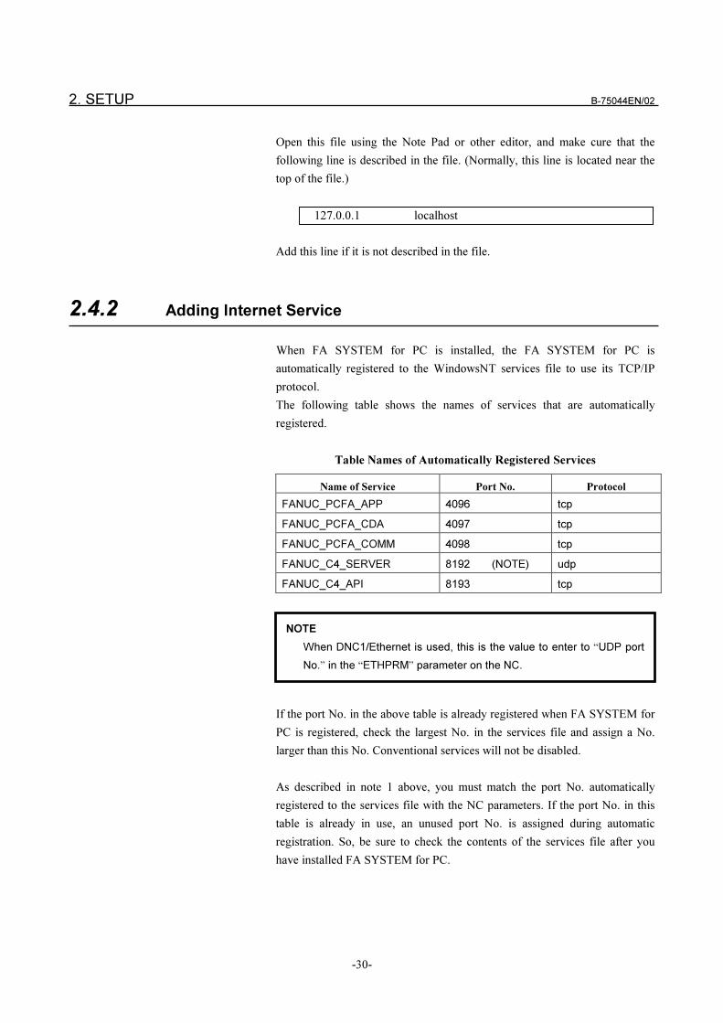
2.4.2 Adding Internet Service
When FA SYSTEM for PC is installed, the FA SYSTEM for PC is
automatically registered to the WindowsNT services file to use its TCP/IP
protocol.
The following table shows the names of services that are automatically
registered.
Table Names of Automatically Registered Services
Name of Service Port No. Protocol
FANUC_PCFA_APP 4096 tcp
FANUC_PCFA_CDA 4097 tcp
FANUC_PCFA_COMM 4098 tcp
FANUC_C4_SERVER 8192 (NOTE) udp
FANUC_C4_API 8193 tcp
If the port No. in the above table is already registered when FA SYSTEM for
PC is registered, check the largest No. in the services file and assign a No.
larger than this No. Conventional services will not be disabled.
As described in note 1 above, you must match the port No. automatically
registered to the services file with the NC parameters. If the port No. in this
table is already in use, an unused port No. is assigned during automatic
registration. So, be sure to check the contents of the services file after you
have installed FA SYSTEM for PC.
127.0.0.1 localhost
NOTE
When DNC1/Ethernet is used, this is the value to enter to “UDP port
No.” in the “ETHPRM” parameter on the NC.
B-75044EN/02 2. SETUP
-31-
The services file will be at the following directory assuming that “c: winnt” is
the directory in which directory WindowsNT is set up. (The directory in
which WindowsNT is set up is registered to system setup variable “windir”
after [System] in the [Control Panel] is started.)
“c: winn system32 drivers etc hosts”
When FA SYSTEM for PC is automatically registered to the services file,
back up the file that was active before FA SYSTEM for PC is registered and
save it to the same directory as the services file.
Set the backup file name in the following format based on the time when FA
SYSTEM for PC was automatically registered:
“services.YYYMMDDhhmm”
where,
YYYY: year according to Western calendar
MM: month
DD: day
hh: hours
mm: minutes
2.4.3 For Setting FA SYSTEM for PC
Both FA LIBRARY(A08B-9510-J510) and NC PROGRAM
MANAGEMENT (A08B-9510-J511) can be installed by the same way.
Please install them by following the next procedure.
1 Log in using a user name having administrator privileges.
2 Insert either “FA LIBRARY Setup Disk (WindowsNT)” or “NC
PROGRAM MANAGEMENT Setup Disk (WindowsNT)” into the
floppy disk drive on your computer.
3 Select [Run] from the Start menu, enter “A: Setup” in the [Name] text
box and press the <OK> button.
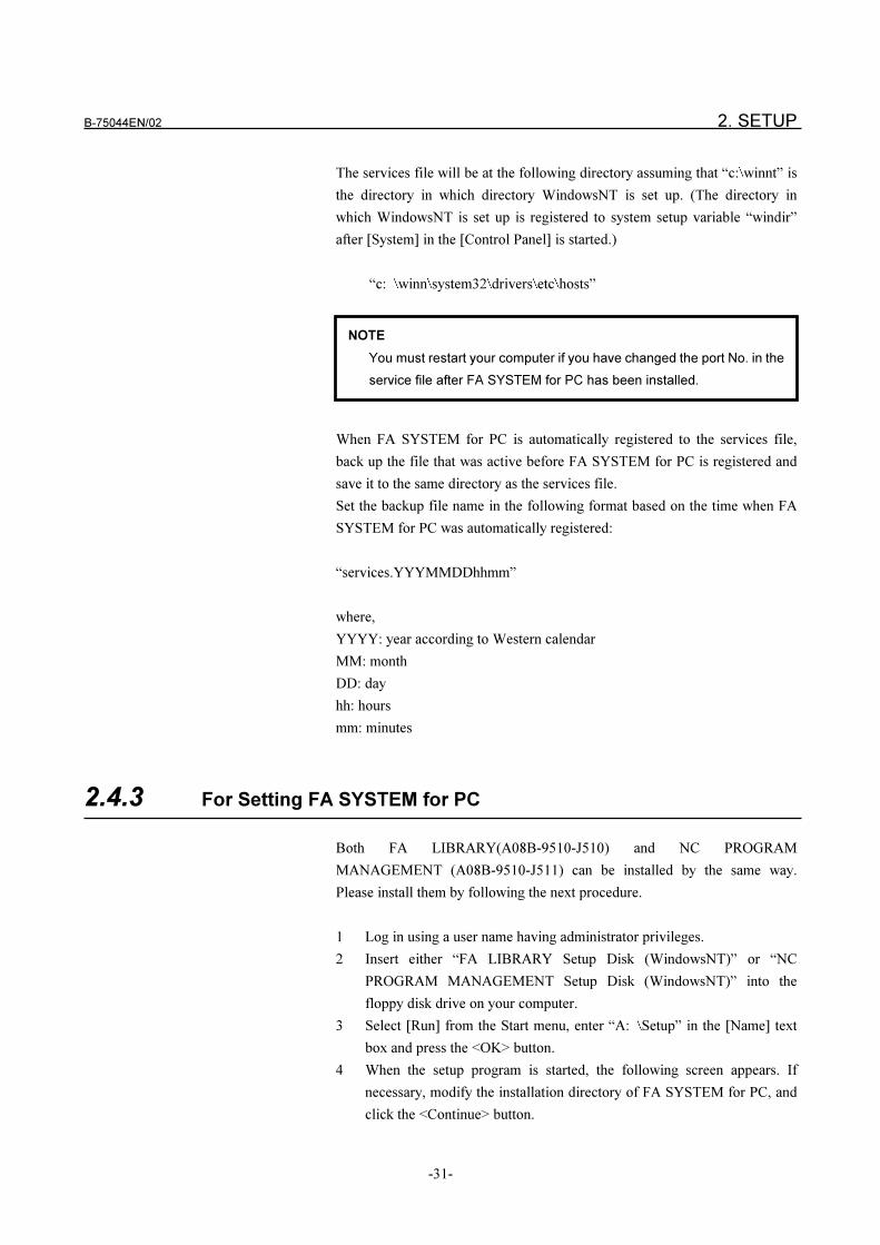
4 When the setup program is started, the following screen appears. If
necessary, modify the installation directory of FA SYSTEM for PC, and
click the <Continue> button.
NOTE
You must restart your computer if you have changed the port No. in the
service file after FA SYSTEM for PC has been installed.
2. SETUP B-75044EN/02
-32-
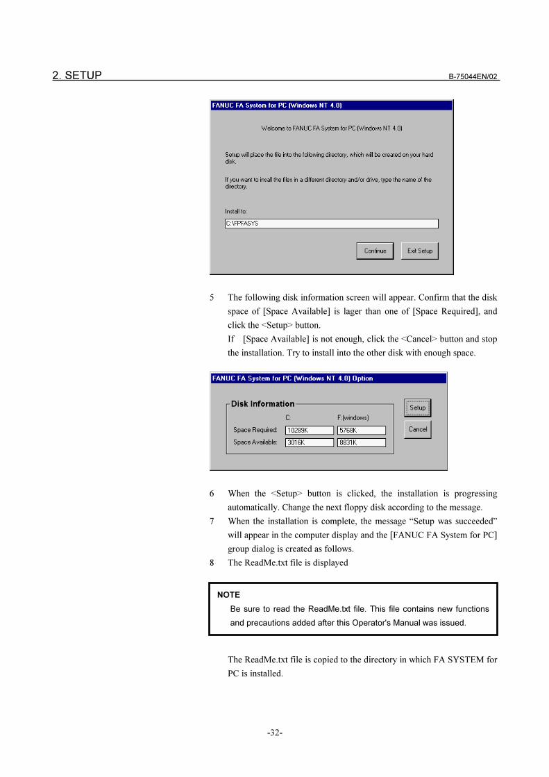
5 The following disk information screen will appear. Confirm that the disk
space of [Space Available] is lager than one of [Space Required], and
click the <Setup> button.
If [Space Available] is not enough, click the <Cancel> button and stop
the installation. Try to install into the other disk with enough space.
6 When the <Setup> button is clicked, the installation is progressing
automatically. Change the next floppy disk according to the message.
7 When the installation is complete, the message “Setup was succeeded”
will appear in the computer display and the [FANUC FA System for PC]
group dialog is created as follows.
8 The ReadMe.txt file is displayed
The ReadMe.txt file is copied to the directory in which FA SYSTEM for
PC is installed.
NOTE
Be sure to read the ReadMe.txt file. This file contains new functions
and precautions added after this Operator's Manual was issued.
B-75044EN/02 2. SETUP
-33-
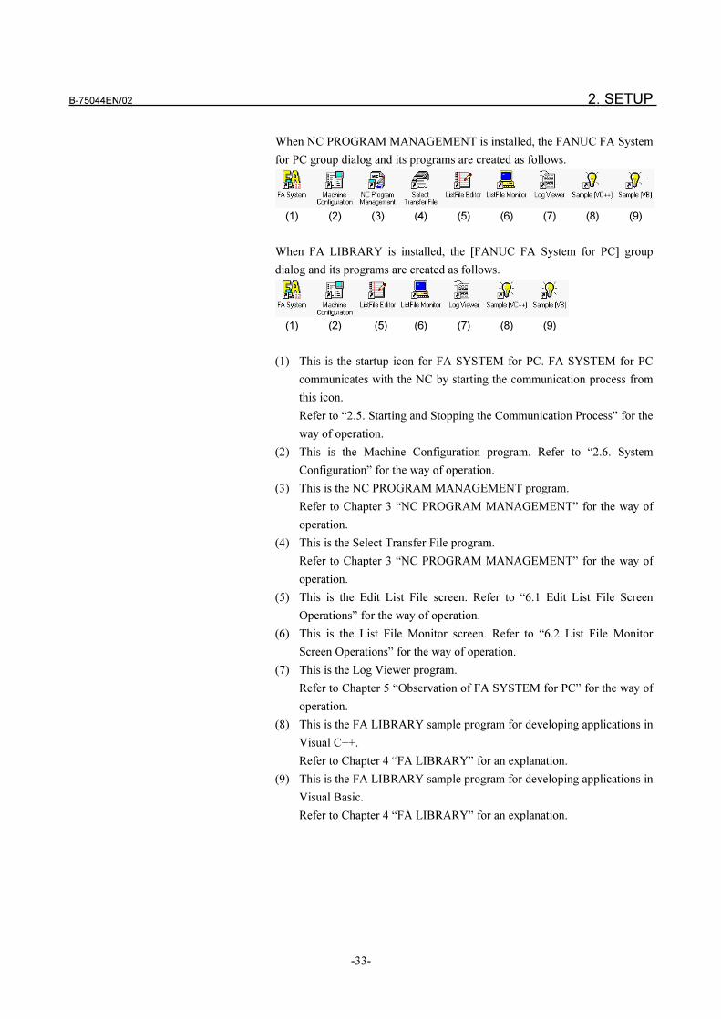
When NC PROGRAM MANAGEMENT is installed, the FANUC FA System
for PC group dialog and its programs are created as follows.
(1) (2) (3) (4) (5) (6) (7) (8) (9)
When FA LIBRARY is installed, the [FANUC FA System for PC] group
dialog and its programs are created as follows.
(1) (2) (5) (6) (7) (8) (9)
(1) This is the startup icon for FA SYSTEM for PC. FA SYSTEM for PC
communicates with the NC by starting the communication process from
this icon.
Refer to “2.5. Starting and Stopping the Communication Process” for the
way of operation.
(2) This is the Machine Configuration program. Refer to “2.6. System
Configuration” for the way of operation.
(3) This is the NC PROGRAM MANAGEMENT program.
Refer to Chapter 3 “NC PROGRAM MANAGEMENT” for the way of
operation.
(4) This is the Select Transfer File program.
Refer to Chapter 3 “NC PROGRAM MANAGEMENT” for the way of
operation.
(5) This is the Edit List File screen. Refer to “6.1 Edit List File Screen
Operations” for the way of operation.
(6) This is the List File Monitor screen. Refer to “6.2 List File Monitor
Screen Operations” for the way of operation.
(7) This is the Log Viewer program.
Refer to Chapter 5 “Observation of FA SYSTEM for PC” for the way of
operation.
(8) This is the FA LIBRARY sample program for developing applications in
Visual C++.
Refer to Chapter 4 “FA LIBRARY” for an explanation.
(9) This is the FA LIBRARY sample program for developing applications in
Visual Basic.
Refer to Chapter 4 “FA LIBRARY” for an explanation.
2. SETUP B-75044EN/02
-34-
2.5 STARTING AND STOPPING THE COMMUNICATION PROCESS
Starting the Communication Process
1 Double-click [FA System] in the [FANUC FA System for PC] group
dialog.
2 The communication process is started in the state of an icon, and the
[FANUC FA System for PC] icon appears at the lower-left corner on the
computer display.
Stopping the Communication Process
1 Double-click the running [FANUC FA System for PC] icon which is
started by the above operation. The following screen will appear.
2 Click the[Exit] of the menu. The communication process will be stopped.
NOTE
If you execute "Start Communication Process" when no machines
have been set in the Machine Setup screen, the error (0x1004011d)
will occur.
Before you start the communication process, execute the system
configuration described in "2.6 System Configuration" and set the
currently connected machine.
B-75044EN/02 2. SETUP
-35-
2.6 SYSTEM CONFIGURATION
To use FA SYSTEM for PC, you must give a distinctive information to each
machine.
By using the Machine Configuration screen, please set up the information
such as a machine number, a machine name, a device port and communication
protocol for connecting to the computer, and the way to manage NC
programs.
Make sure that stop the communication process before the Machine
Configuration screen is started.
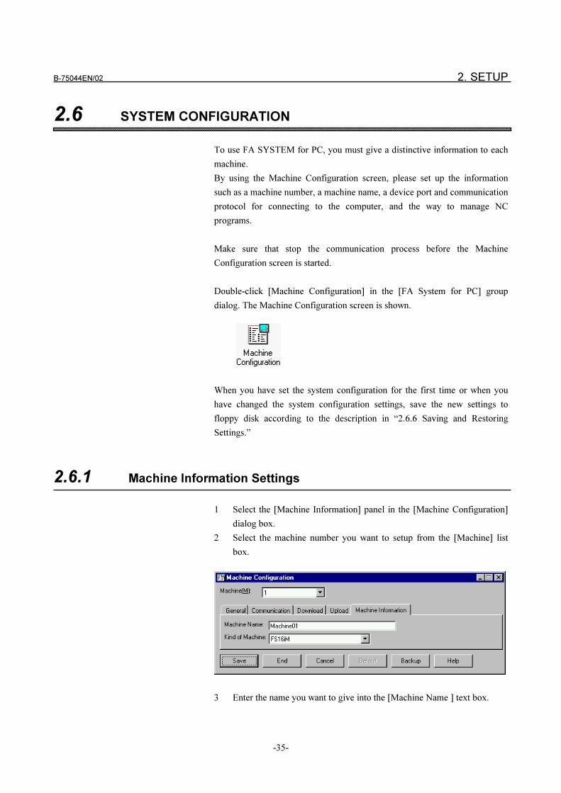
Double-click [Machine Configuration] in the [FA System for PC] group
dialog. The Machine Configuration screen is shown.
When you have set the system configuration for the first time or when you
have changed the system configuration settings, save the new settings to
floppy disk according to the description in “2.6.6 Saving and Restoring
Settings.”
2.6.1 Machine Information Settings
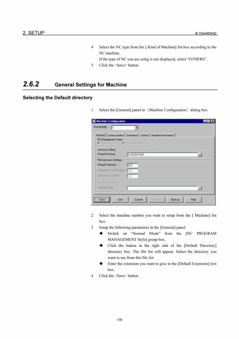
1 Select the [Machine Information] panel in the [Machine Configuration]
dialog box.
2 Select the machine number you want to setup from the [Machine] list
box.
3 Enter the name you want to give into the [Machine Name ] text box.
2. SETUP B-75044EN/02
-36-
4 Select the NC type from the [ Kind of Machine] list box according to the
NC machine.
If the type of NC you are using is not displayed, select “OTHERS”.
5 Click the <Save> button.
2.6.2 General Settings for Machine
Selecting the Default directory
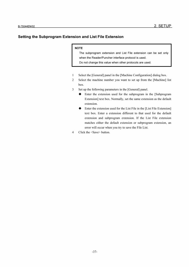
1 Select the [General] panel in�Machine Configuration�dialog box.
2 Select the machine number you want to setup from the [ Machine] list
box.
3 Setup the following parameters in the [General] panel.
� Switch on “Normal Mode” from the [NC PROGRAM
MANAGEMENT Style] group box.
� Click the button in the right side of the [Default Directory]
directory box. The file list will appear. Select the directory you
want to use from this file list.
� Enter the extension you want to give in the [Default Extension] text
box.
4 Click the <Save> button.
B-75044EN/02 2. SETUP
-37-
Setting the Subprogram Extension and List File Extension
1 Select the [General] panel in the [Machine Configuration] dialog box.
2 Select the machine number you want to set up from the [Machine] list
box.
3 Set up the following parameters in the [General] panel.
� Enter the extension used for the subprogram in the [Subprogram
Extension] text box. Normally, set the same extension as the default
extension.
� Enter the extension used for the List File in the [List File Extension]
text box. Enter a extension different to that used for the default
extension and subprogram extension. If the List File extension
matches either the default extension or subprogram extension, an
error will occur when you try to save the File List.
4 Click the <Save> button.
NOTE
The subprogram extension and List File extension can be set only
when the Reader/Puncher interface protocol is used.
Do not change this value when other protocols are used.
2. SETUP B-75044EN/02
-38-
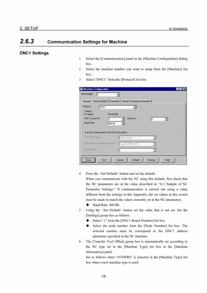
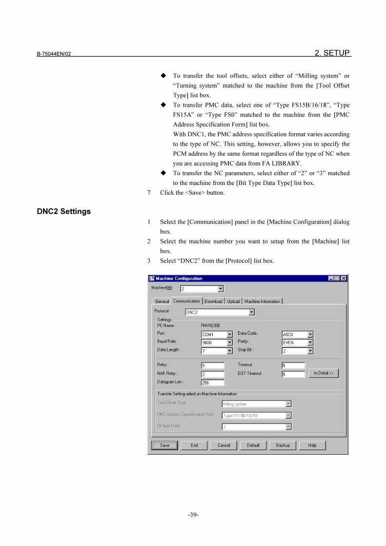
2.6.3 Communication Settings for Machine
DNC1 Settings
1 Select the [Communication] panel in the [Machine Configuration] dialog
box.
2 Select the machine number you want to setup from the [Machine] list
box..
3 Select “DNC1” from the [Protocol] list box.
4 Press the <Set Default> button and set the default.
When you communicate with the NC using this default, first check that
the NC parameters are at the value described in “A.1 Sample of NC
Parameter Settings.” If communication is carried out using a value
different from the settings in this Appendix, the set values in this screen
must be made to match the values currently set in the NC parameters.
� Baud Rate: 460.8K
5 Using the <Set Default> button set the value that is not set. Set the
[Settings] group box as follows:
� Select “1” from the [DNC1 Board Number] list box.
� Select the node number form the [Node Number] list box. The
selected number must be correspond to the DNC1 address
parameter specified in the NC machine.
6 The [Transfer Tool Offset] group box is automatically set according to
the NC type set in the [Machine Type] list box in the [Machine
Information] panel.
Set as follows when “OTHERS” is selected in the [Machine Type] list
box when a new machine type is used:
B-75044EN/02 2. SETUP
-39-
� To transfer the tool offsets, select either of “Milling system” or
“Turning system” matched to the machine from the [Tool Offset
Type] list box.
� To transfer PMC data, select one of “Type FS15B/16/18”, “Type
FS15A” or “Type FS0” matched to the machine from the [PMC
Address Specification Form] list box.
With DNC1, the PMC address specification format varies according
to the type of NC. This setting, however, allows you to specify the
PCM address by the same format regardless of the type of NC when
you are accessing PMC data from FA LIBRARY.
� To transfer the NC parameters, select either of “2” or “3” matched
to the machine from the [Bit Type Data Type] list box.
7 Click the <Save> button.
DNC2 Settings
1 Select the [Communication] panel in the [Machine Configuration] dialog
box.
2 Select the machine number you want to setup from the [Machine] list
box.
3 Select “DNC2” from the [Protocol] list box.
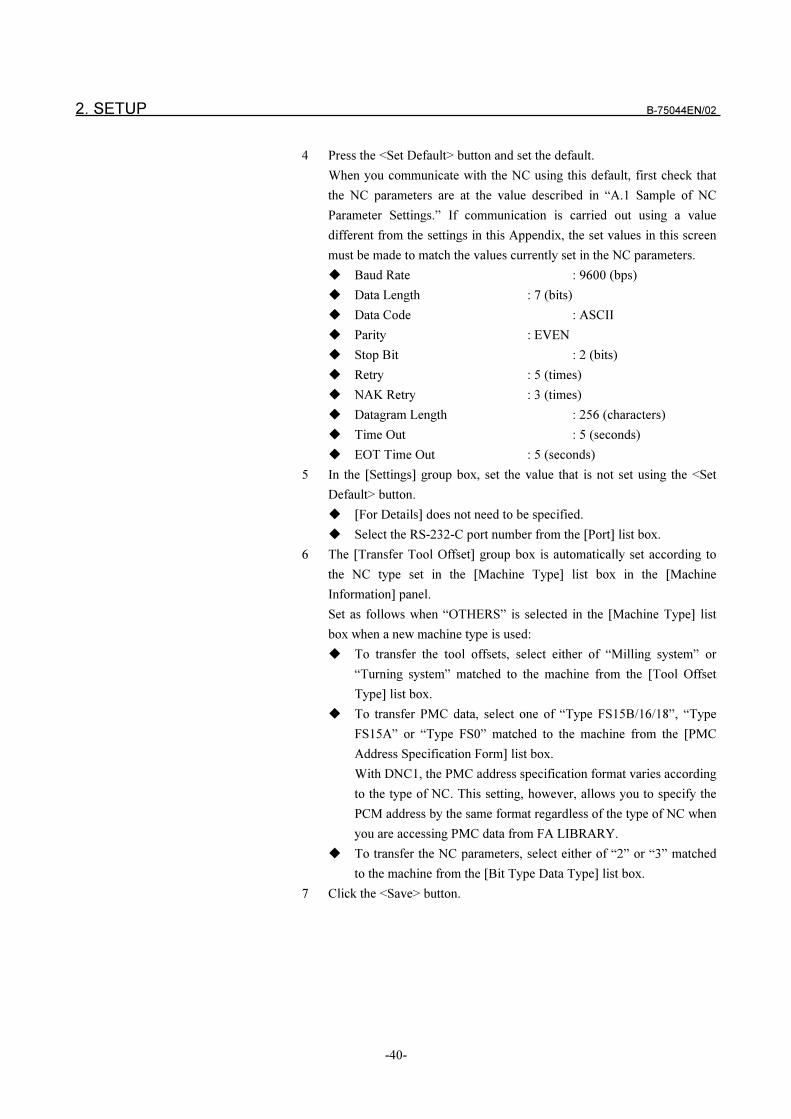
2. SETUP B-75044EN/02
-40-
4 Press the <Set Default> button and set the default.
When you communicate with the NC using this default, first check that
the NC parameters are at the value described in “A.1 Sample of NC
Parameter Settings.” If communication is carried out using a value
different from the settings in this Appendix, the set values in this screen
must be made to match the values currently set in the NC parameters.
� Baud Rate : 9600 (bps)
� Data Length : 7 (bits)
� Data Code : ASCII
� Parity : EVEN
� Stop Bit : 2 (bits)
� Retry : 5 (times)
� NAK Retry : 3 (times)
� Datagram Length : 256 (characters)
� Time Out : 5 (seconds)
� EOT Time Out : 5 (seconds)
5 In the [Settings] group box, set the value that is not set using the <Set
Default> button.
� [For Details] does not need to be specified.
� Select the RS-232-C port number from the [Port] list box.
6 The [Transfer Tool Offset] group box is automatically set according to
the NC type set in the [Machine Type] list box in the [Machine
Information] panel.
Set as follows when “OTHERS” is selected in the [Machine Type] list
box when a new machine type is used:
� To transfer the tool offsets, select either of “Milling system” or
“Turning system” matched to the machine from the [Tool Offset
Type] list box.
� To transfer PMC data, select one of “Type FS15B/16/18”, “Type
FS15A” or “Type FS0” matched to the machine from the [PMC
Address Specification Form] list box.
With DNC1, the PMC address specification format varies according
to the type of NC. This setting, however, allows you to specify the
PCM address by the same format regardless of the type of NC when
you are accessing PMC data from FA LIBRARY.
� To transfer the NC parameters, select either of “2” or “3” matched
to the machine from the [Bit Type Data Type] list box.
7 Click the <Save> button.
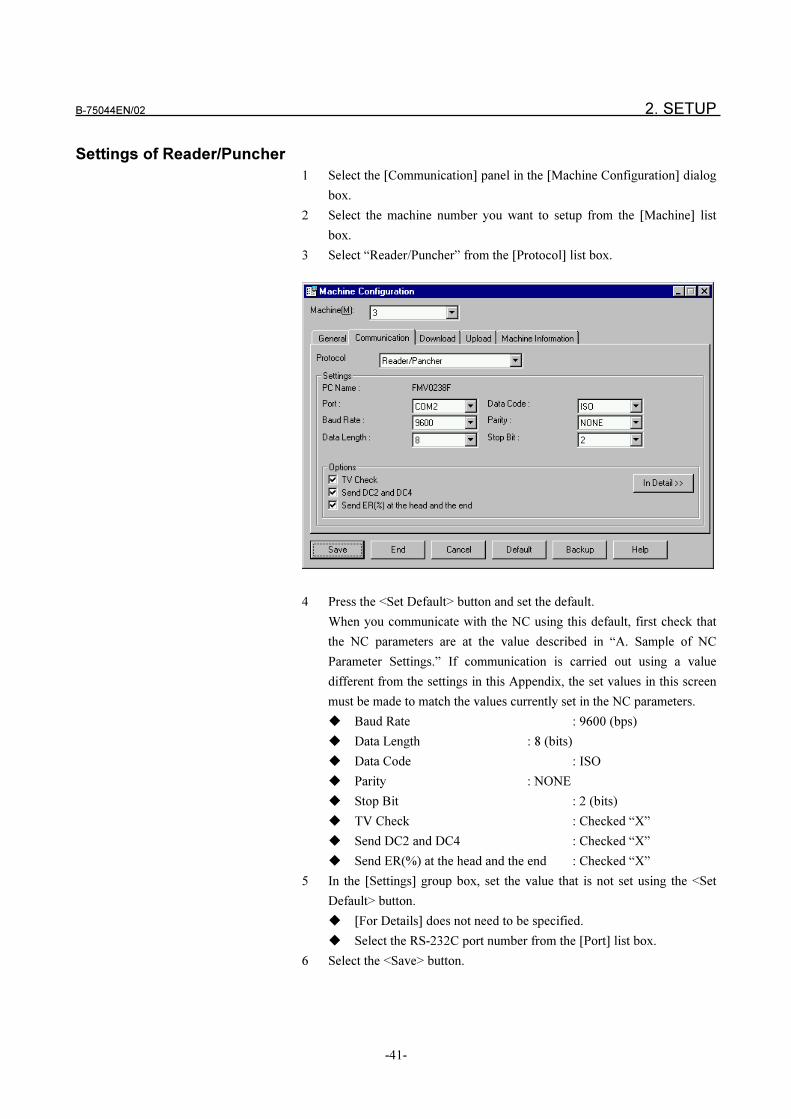
B-75044EN/02 2. SETUP
-41-
Settings of Reader/Puncher
1 Select the [Communication] panel in the [Machine Configuration] dialog
box.
2 Select the machine number you want to setup from the [Machine] list
box.
3 Select “Reader/Puncher” from the [Protocol] list box.
4 Press the <Set Default> button and set the default.
When you communicate with the NC using this default, first check that
the NC parameters are at the value described in “A. Sample of NC
Parameter Settings.” If communication is carried out using a value
different from the settings in this Appendix, the set values in this screen
must be made to match the values currently set in the NC parameters.
� Baud Rate : 9600 (bps)
� Data Length : 8 (bits)
� Data Code : ISO
� Parity : NONE
� Stop Bit : 2 (bits)
� TV Check : Checked “X”
� Send DC2 and DC4 : Checked “X”
� Send ER(%) at the head and the end : Checked “X”
5 In the [Settings] group box, set the value that is not set using the <Set
Default> button.
� [For Details] does not need to be specified.
� Select the RS-232C port number from the [Port] list box.
6 Select the <Save> button.
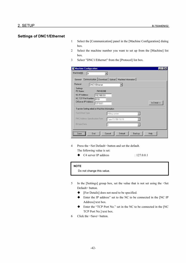
2. SETUP B-75044EN/02
-42-
Settings of DNC1/Ethernet
1 Select the [Communication] panel in the [Machine Configuration] dialog
box.
2 Select the machine number you want to set up from the [Machine] list
box.
3 Select "DNC1/Ethernet" from the [Protocol] list box.
4 Press the <Set Default> button and set the default.
The following value is set:
� C4 server IP address : 127.0.0.1
5 In the [Settings] group box, set the value that is not set using the <Set
Default> button.
� [For Details] does not need to be specified.
� Enter the IP address” set to the NC to be connected in the [NC IP
Address] text box.
� Enter the “TCP Port No.” set in the NC to be connected in the [NC
TCP Port No.] text box.
6 Click the <Save> button.
NOTE
Do not change this value.

B-75044EN/02 2. SETUP
-43-
2.6.4 Download Settings for Machine
You can set the subprogram transfer method and List File transfer method.
For details on the subprogram transfer function, see “1.5 Subprogram
Transfer Function,” and for details on the List File transfer function, see “1.6
List File Transfer Function.”
2 If you select either of “Separate Transfer” or “Extended Transfer” in the
[Transfer Styles for Sub Programs] frame, you can set the following:
� Calling Type
You can set the code used for calling the subprogram.
You can set a combination of the M98, G65 and G66 codes.
� Masks of Sub Programs
You can set the subprograms not to transfer even if a subprogram is
called by the main program. You can set this in 1000-line units. So,
for example, you can set “Not to send subprograms in lines 8000 to
9000 as they are stored in NC memory.”
NOTE
You can set the subprogram transfer method and List File transfer
method only when the Reader/Puncher interface protocol is used. Do
not change this value when other protocols are used.
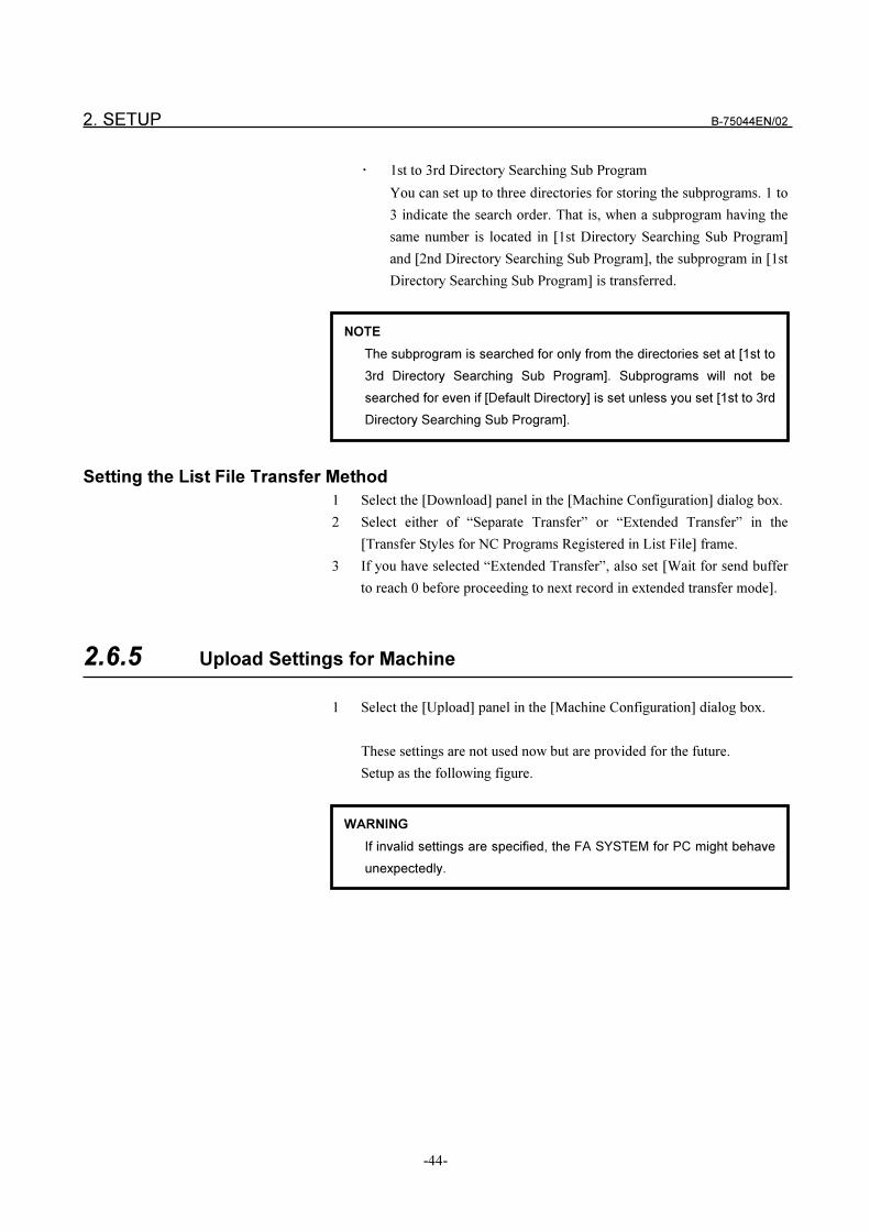
2. SETUP B-75044EN/02
-44-
� 1st to 3rd Directory Searching Sub Program
You can set up to three directories for storing the subprograms. 1 to
3 indicate the search order. That is, when a subprogram having the
same number is located in [1st Directory Searching Sub Program]
and [2nd Directory Searching Sub Program], the subprogram in [1st
Directory Searching Sub Program] is transferred.
Setting the List File Transfer Method
1 Select the [Download] panel in the [Machine Configuration] dialog box.
2 Select either of “Separate Transfer” or “Extended Transfer” in the
[Transfer Styles for NC Programs Registered in List File] frame.
3 If you have selected “Extended Transfer”, also set [Wait for send buffer
to reach 0 before proceeding to next record in extended transfer mode].
2.6.5 Upload Settings for Machine
1 Select the [Upload] panel in the [Machine Configuration] dialog box.
These settings are not used now but are provided for the future.
Setup as the following figure.
NOTE
The subprogram is searched for only from the directories set at [1st to
3rd Directory Searching Sub Program]. Subprograms will not be
searched for even if [Default Directory] is set unless you set [1st to 3rd
Directory Searching Sub Program].
WARNING
If invalid settings are specified, the FA SYSTEM for PC might behave
unexpectedly.
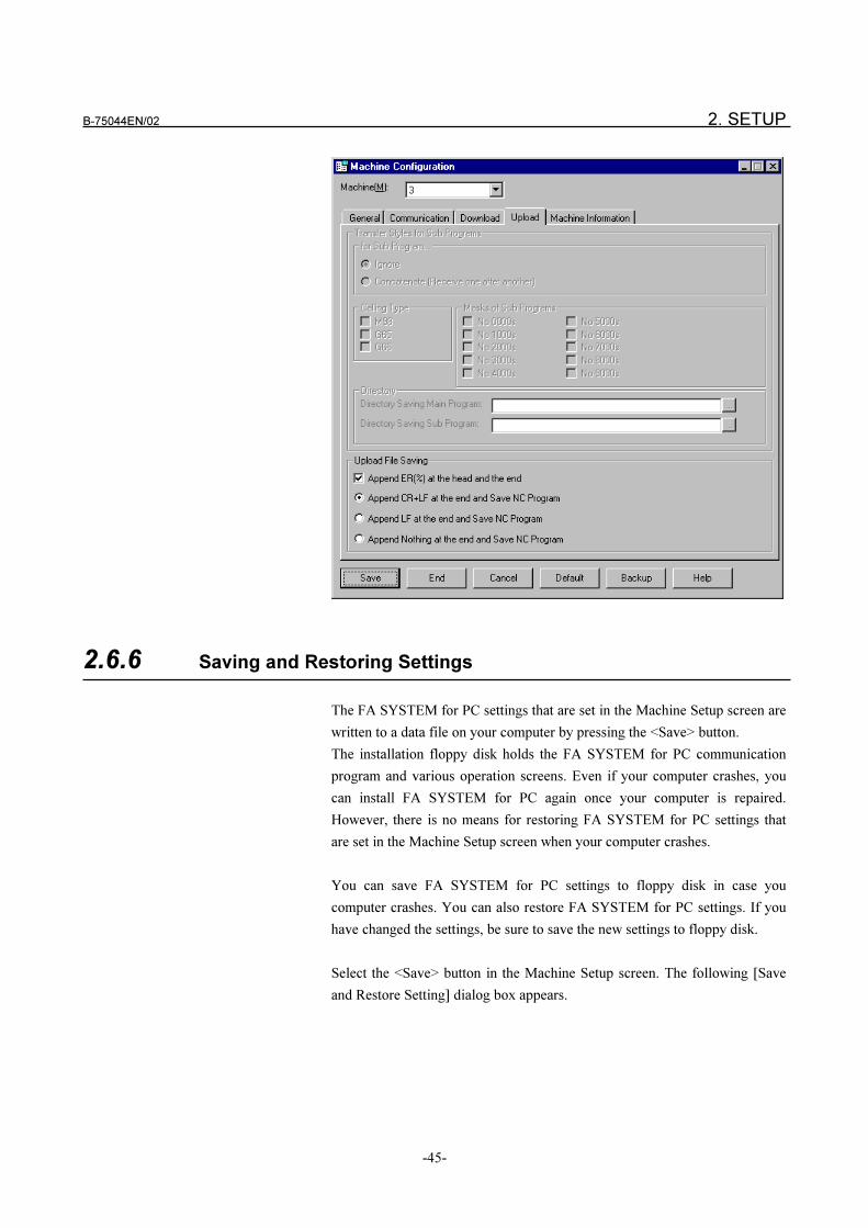
B-75044EN/02 2. SETUP
-45-
2.6.6 Saving and Restoring Settings
The FA SYSTEM for PC settings that are set in the Machine Setup screen are
written to a data file on your computer by pressing the <Save> button.
The installation floppy disk holds the FA SYSTEM for PC communication
program and various operation screens. Even if your computer crashes, you
can install FA SYSTEM for PC again once your computer is repaired.
However, there is no means for restoring FA SYSTEM for PC settings that
are set in the Machine Setup screen when your computer crashes.
You can save FA SYSTEM for PC settings to floppy disk in case you
computer crashes. You can also restore FA SYSTEM for PC settings. If you
have changed the settings, be sure to save the new settings to floppy disk.
Select the <Save> button in the Machine Setup screen. The following [Save
and Restore Setting] dialog box appears.
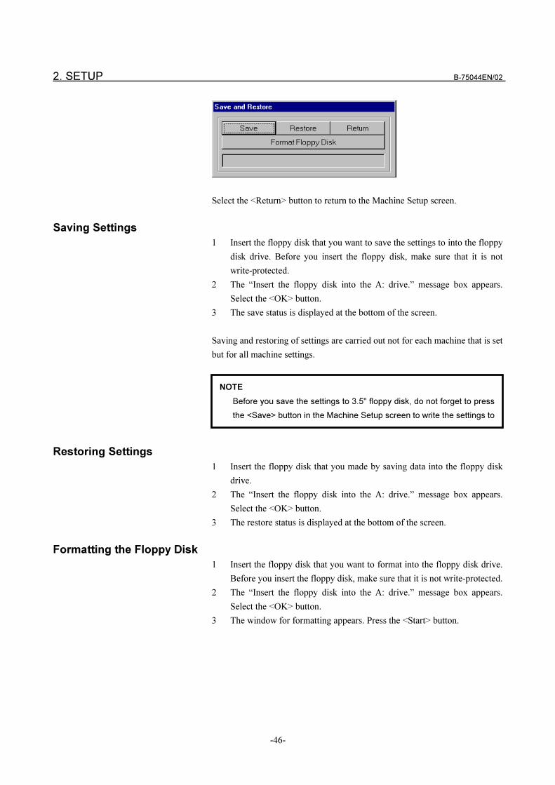
2. SETUP B-75044EN/02
-46-
Select the <Return> button to return to the Machine Setup screen.
Saving Settings
1 Insert the floppy disk that you want to save the settings to into the floppy
disk drive. Before you insert the floppy disk, make sure that it is not
write-protected.
2 The “Insert the floppy disk into the A: drive.” message box appears.
Select the <OK> button.
3 The save status is displayed at the bottom of the screen.
Saving and restoring of settings are carried out not for each machine that is set
but for all machine settings.
Restoring Settings
1 Insert the floppy disk that you made by saving data into the floppy disk
drive.
2 The “Insert the floppy disk into the A: drive.” message box appears.
Select the <OK> button.
3 The restore status is displayed at the bottom of the screen.
Formatting the Floppy Disk
1 Insert the floppy disk that you want to format into the floppy disk drive.
Before you insert the floppy disk, make sure that it is not write-protected.
2 The “Insert the floppy disk into the A: drive.” message box appears.
Select the <OK> button.
3 The window for formatting appears. Press the <Start> button.
NOTE
Before you save the settings to 3.5" floppy disk, do not forget to press
the <Save> button in the Machine Setup screen to write the settings to

B-75044EN/02 3. NC PROGRAM MANAGEMENT
-47-
3 NC PROGRAM MANAGEMENT
3. NC PROGRAM MANAGEMENT B-75044EN/02
-48-
3.1 OUTLINE
NC PROGRAM MANAGEMENT is the software package that allows a
computer to function as an NC program file sever to connect multiple NCs.
NC PROGRAM MANAGEMENT has the following functions according to
the communicating capability.
(1) For DNC1 or DNC2
The following functions can be executed from the menu of NC
PROGRAM MANAGEMENT.
� A computer can download an NC program to NC.
� A computer can upload an NC program from NC.
� NC PROGRAM MANAGEMENT can show the list of NC
programs stored in the NC memory.
� NC PROGRAM MANAGEMENT can delete an NC program
stored in NC.
The following functions can be executed by operating CRT/MDI of NC.
� An NC machine can read an NC program from a computer.
� An NC machine can punch a NC program to a computer.
� NC can call an NC program for DNC operation.
(2) For DNC1/Ethernet
The following functions can be executed from the menu of NC
PROGRAM MANAGEMENT.
� A computer can download an NC program to the NC memory.
� A computer can upload an NC program from the NC memory.
� NC PROGRAM MANAGEMENT can show the list of NC
programs stored in the NC memory.
� NC PROGRAM MANAGEMENT can delete an NC program
stored in an NC.
(3) For Reader/Puncher
The following functions can be executed by operating on CRT/MDI of
NC
� An NC machine can read an NC program from a computer.
� An NC machine can punch a NC program to a computer.
� An NC machine can show the list of NC programs stored in a
computer.
� An NC machine can delete a NC program stored in a computer.
� An NC machine can call an NC program for DNC operation.
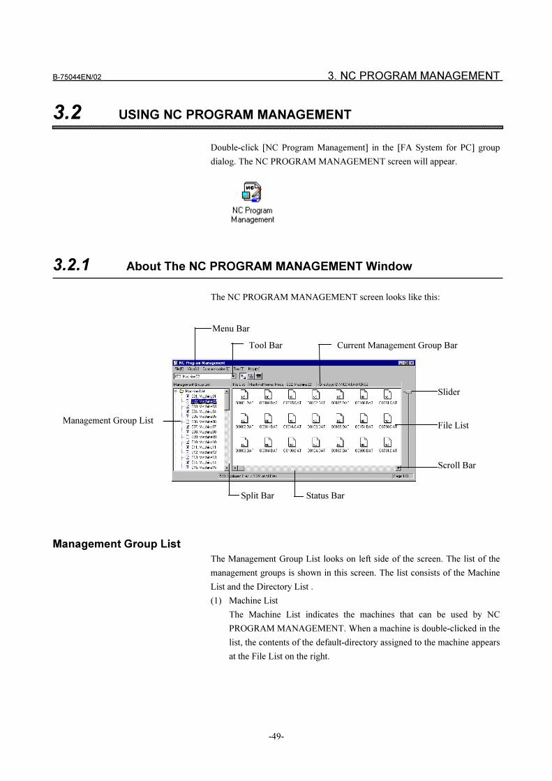
B-75044EN/02 3. NC PROGRAM MANAGEMENT
-49-
3.2 USING NC PROGRAM MANAGEMENT
Double-click [NC Program Management] in the [FA System for PC] group
dialog. The NC PROGRAM MANAGEMENT screen will appear.
3.2.1 About The NC PROGRAM MANAGEMENT Window
The NC PROGRAM MANAGEMENT screen looks like this:
Menu Bar
Tool Bar Current Management Group Bar
Slider
File List
Scroll Bar
Split Bar Status Bar
Management Group List
Management Group List
The Management Group List looks on left side of the screen. The list of the
management groups is shown in this screen. The list consists of the Machine
List and the Directory List .
(1) Machine List
The Machine List indicates the machines that can be used by NC
PROGRAM MANAGEMENT. When a machine is double-clicked in the
list, the contents of the default-directory assigned to the machine appears
at the File List on the right.
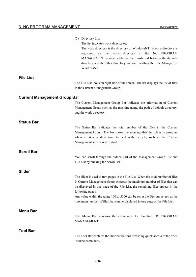
3. NC PROGRAM MANAGEMENT B-75044EN/02
-50-
(2) Directory List
The list indicates work directories.
The work directory is the directory of WindowsNT. When a directory is
registered as the work directory in the NC PROGRAM
MANAGEMENT screen, a file can be transferred between the default-
directory and the other directory without handling the File Manager of
WindowsNT.
File List
The File List looks on right side of the screen. The list displays the list of files
in the Current Management Group.
Current Management Group Bar
The Current Management Group Bar indicates the information of Current
Management Group such as the machine name, the path of default-directory,
and the work directory.
Status Bar
The Status Bar indicates the total number of the files in the Current
Management Group. The bar shows the message that the job is in progress
when it takes a short time to deal with the job, such as the Current
Management screen is refreshed.
Scroll Bar
You can scroll through the hidden part of the Management Group List and
File List by clicking the Scroll Bar.
Slider
The slider is used to turn pages in the File List. When the total number of files
in Current Management Group exceeds the maximum number of files that can
be displayed in one page of the File List, the remaining files appear in the
following pages.
Any value within the range 100 to 5000 can be set in the Options screen as the
maximum number of files that can be displayed in one page of the File List.
Menu Bar
The Menu Bar contains the commands for handling NC PROGRAM
MANAGEMENT.
Tool Bar
The Tool Bar contains the shortcut buttons providing quick access to the often
utilized commands .
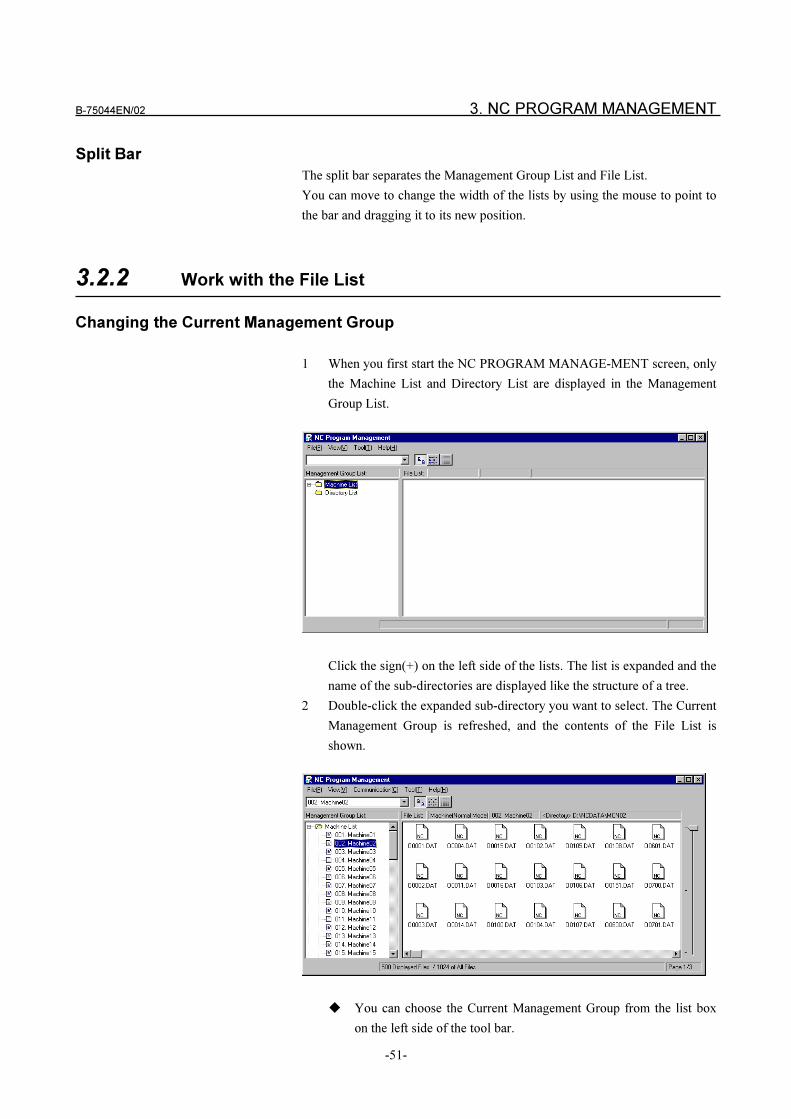
B-75044EN/02 3. NC PROGRAM MANAGEMENT
-51-
Split Bar
The split bar separates the Management Group List and File List.
You can move to change the width of the lists by using the mouse to point to
the bar and dragging it to its new position.
3.2.2 Work with the File List
Changing the Current Management Group
1 When you first start the NC PROGRAM MANAGE-MENT screen, only
the Machine List and Directory List are displayed in the Management
Group List.
Click the sign(+) on the left side of the lists. The list is expanded and the
name of the sub-directories are displayed like the structure of a tree.
2 Double-click the expanded sub-directory you want to select. The Current
Management Group is refreshed, and the contents of the File List is
shown.
� You can choose the Current Management Group from the list box
on the left side of the tool bar.
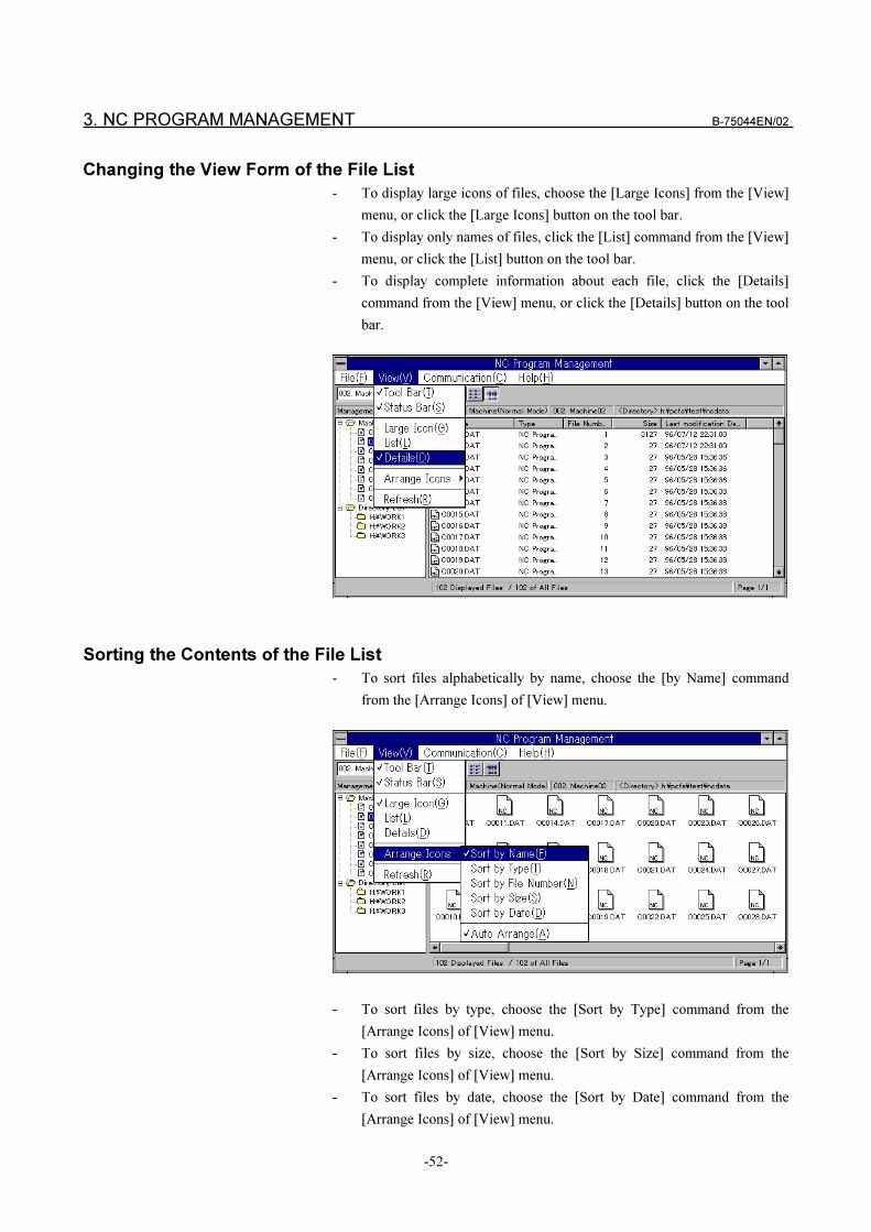
3. NC PROGRAM MANAGEMENT B-75044EN/02
-52-
Changing the View Form of the File List
- To display large icons of files, choose the [Large Icons] from the [View]
menu, or click the [Large Icons] button on the tool bar.
- To display only names of files, click the [List] command from the [View]
menu, or click the [List] button on the tool bar.
- To display complete information about each file, click the [Details]
command from the [View] menu, or click the [Details] button on the tool
bar.
Sorting the Contents of the File List
- To sort files alphabetically by name, choose the [by Name] command
from the [Arrange Icons] of [View] menu.
- To sort files by type, choose the [Sort by Type] command from the
[Arrange Icons] of [View] menu.
- To sort files by size, choose the [Sort by Size] command from the
[Arrange Icons] of [View] menu.
- To sort files by date, choose the [Sort by Date] command from the
[Arrange Icons] of [View] menu.
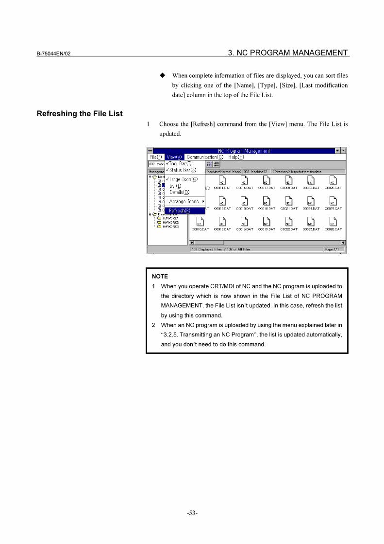
B-75044EN/02 3. NC PROGRAM MANAGEMENT
-53-
� When complete information of files are displayed, you can sort files
by clicking one of the [Name], [Type], [Size], [Last modification
date] column in the top of the File List.
Refreshing the File List
1 Choose the [Refresh] command from the [View] menu. The File List is
updated.
NOTE
1 When you operate CRT/MDI of NC and the NC program is uploaded to
the directory which is now shown in the File List of NC PROGRAM
MANAGEMENT, the File List isn’t updated. In this case, refresh the list
by using this command.
2 When an NC program is uploaded by using the menu explained later in
“3.2.5. Transmitting an NC Program”, the list is updated automatically,
and you don’t need to do this command.
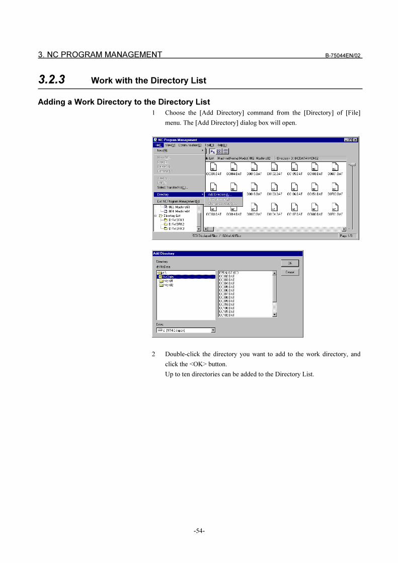
3. NC PROGRAM MANAGEMENT B-75044EN/02
-54-
3.2.3 Work with the Directory List
Adding a Work Directory to the Directory List
1 Choose the [Add Directory] command from the [Directory] of [File]
menu. The [Add Directory] dialog box will open.
2 Double-click the directory you want to add to the work directory, and
click the <OK> button.
Up to ten directories can be added to the Directory List.
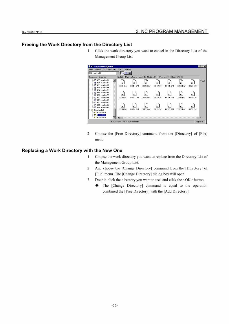
B-75044EN/02 3. NC PROGRAM MANAGEMENT
-55-
Freeing the Work Directory from the Directory List
1 Click the work directory you want to cancel in the Directory List of the
Management Group List
2 Choose the [Free Directory] command from the [Directory] of [File]
menu.
Replacing a Work Directory with the New One
1 Choose the work directory you want to replace from the Directory List of
the Management Group List.
2 And choose the [Change Directory] command from the [Directory] of
[File] menu. The [Change Directory] dialog box will open.
3 Double-click the directory you want to use, and click the <OK> button.
� The [Change Directory] command is equal to the operation
combined the [Free Directory] with the [Add Directory].
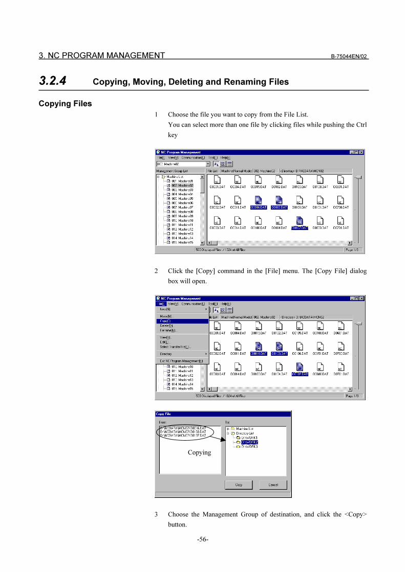
3. NC PROGRAM MANAGEMENT B-75044EN/02
-56-
3.2.4 Copying, Moving, Deleting and Renaming Files
Copying Files
1 Choose the file you want to copy from the File List.
You can select more than one file by clicking files while pushing the Ctrl
key
2 Click the [Copy] command in the [File] menu. The [Copy File] dialog
box will open.
3 Choose the Management Group of destination, and click the <Copy>
button.
Copying
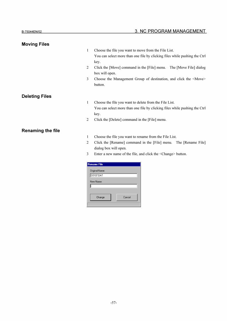
B-75044EN/02 3. NC PROGRAM MANAGEMENT
-57-
Moving Files
1 Choose the file you want to move from the File List.
You can select more than one file by clicking files while pushing the Ctrl
key.
2 Click the [Move] command in the [File] menu. The [Move File] dialog
box will open.
3 Choose the Management Group of destination, and click the <Move>
button.
Deleting Files
1 Choose the file you want to delete from the File List.
You can select more than one file by clicking files while pushing the Ctrl
key.
2 Click the [Delete] command in the [File] menu.
Renaming the file
1 Choose the file you want to rename from the File List.
2 Click the [Rename] command in the [File] menu. The [Rename File]
dialog box will open.
3 Enter a new name of the file, and click the <Change> button.
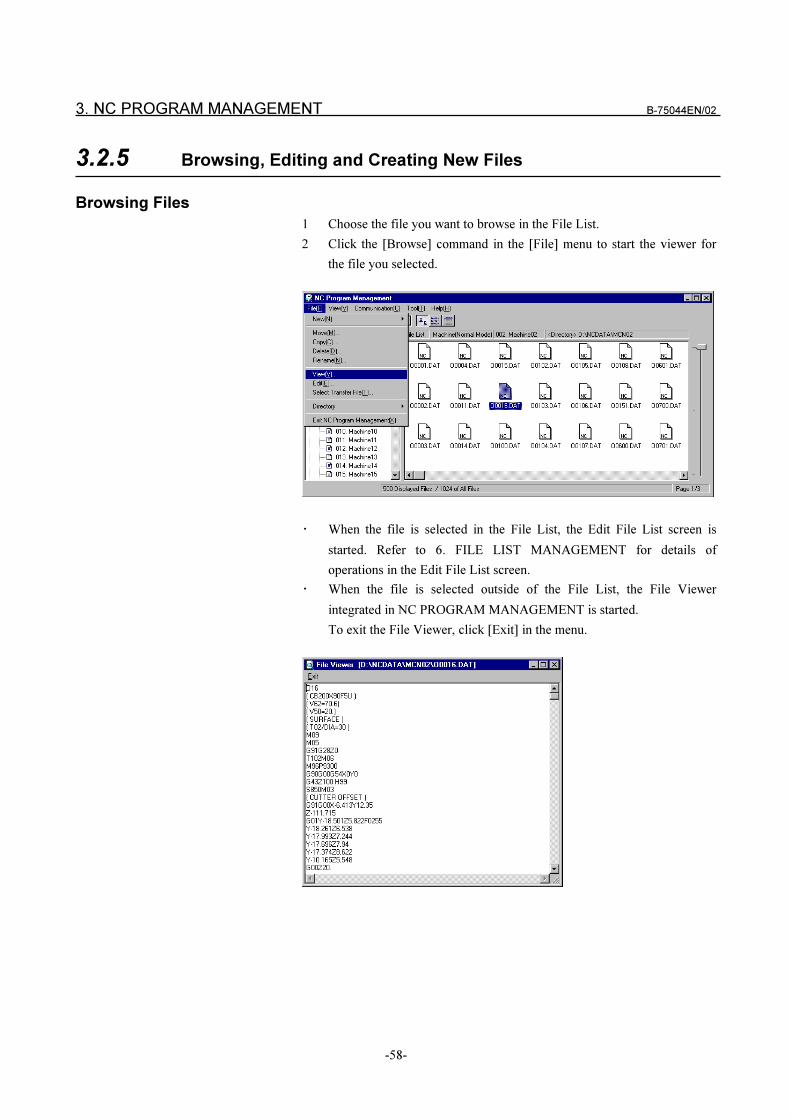
3. NC PROGRAM MANAGEMENT B-75044EN/02
-58-
3.2.5 Browsing, Editing and Creating New Files
Browsing Files
1 Choose the file you want to browse in the File List.
2 Click the [Browse] command in the [File] menu to start the viewer for
the file you selected.
� When the file is selected in the File List, the Edit File List screen is
started. Refer to 6. FILE LIST MANAGEMENT for details of
operations in the Edit File List screen.
� When the file is selected outside of the File List, the File Viewer
integrated in NC PROGRAM MANAGEMENT is started.
To exit the File Viewer, click [Exit] in the menu.
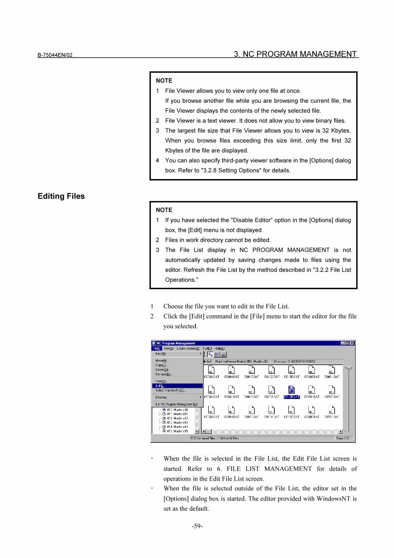
B-75044EN/02 3. NC PROGRAM MANAGEMENT
-59-
Editing Files
1 Choose the file you want to edit in the File List.
2 Click the [Edit] command in the [File] menu to start the editor for the file
you selected.
� When the file is selected in the File List, the Edit File List screen is
started. Refer to 6. FILE LIST MANAGEMENT for details of
operations in the Edit File List screen.
� When the file is selected outside of the File List, the editor set in the
[Options] dialog box is started. The editor provided with WindowsNT is
set as the default.
NOTE
1 File Viewer allows you to view only one file at once.
If you browse another file while you are browsing the current file, the
File Viewer displays the contents of the newly selected file.
2 File Viewer is a text viewer. It does not allow you to view binary files.
3 The largest file size that File Viewer allows you to view is 32 Kbytes.
When you browse files exceeding this size limit, only the first 32
Kbytes of the file are displayed.
4 You can also specify third-party viewer software in the [Options] dialog
box. Refer to "3.2.8 Setting Options" for details.
NOTE
1 If you have selected the "Disable Editor" option in the [Options] dialog
box, the [Edit] menu is not displayed.
2 Files in work directory cannot be edited.
3 The File List display in NC PROGRAM MANAGEMENT is not
automatically updated by saving changes made to files using the
editor. Refresh the File List by the method described in "3.2.2 File List
Operations."
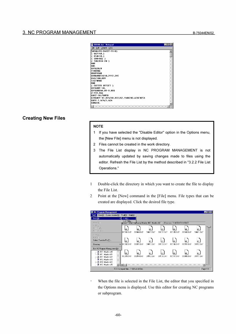
3. NC PROGRAM MANAGEMENT B-75044EN/02
-60-
Creating New Files
1 Double-click the directory in which you want to create the file to display
the File List.
2 Point at the [New] command in the [File] menu. File types that can be
created are displayed. Click the desired file type.
� When the file is selected in the File List, the editor that you specified in
the Options menu is displayed. Use this editor for creating NC programs
or subprogram.
NOTE
1 If you have selected the "Disable Editor" option in the Options menu,
the [New File] menu is not displayed.
2 Files cannot be created in the work directory.
3 The File List display in NC PROGRAM MANAGEMENT is not
automatically updated by saving changes made to files using the
editor. Refresh the File List by the method described in "3.2.2 File List
Operations."
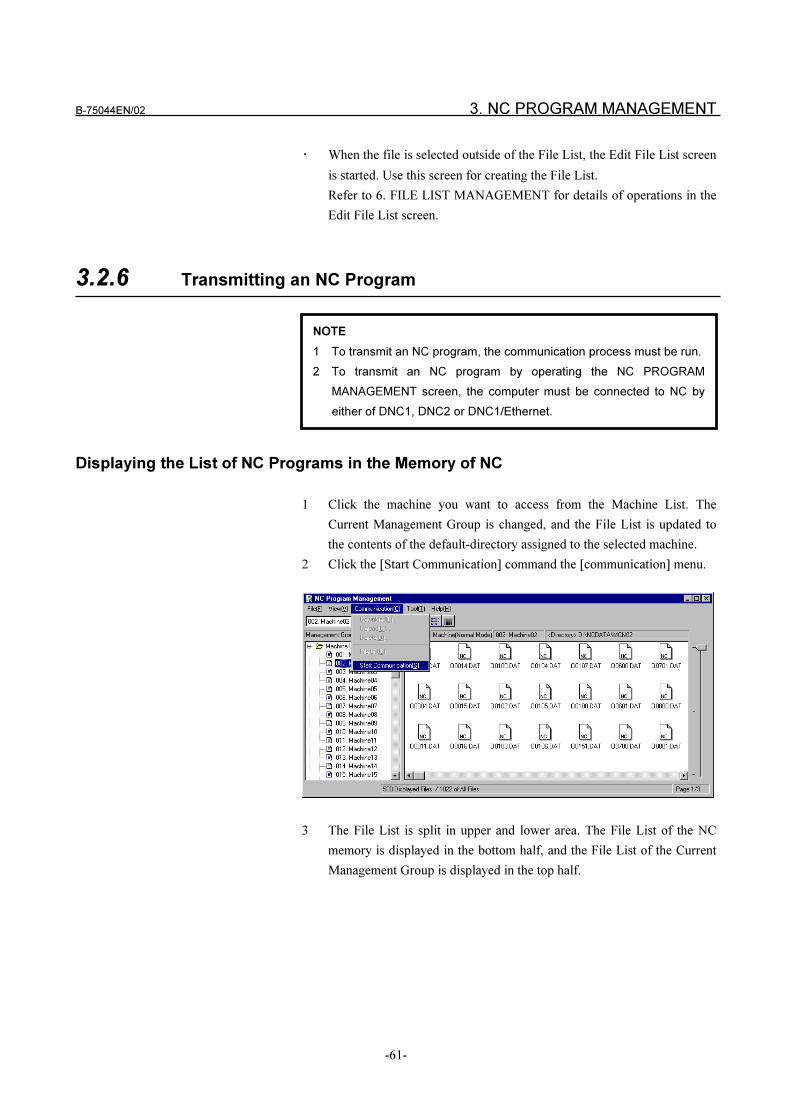
B-75044EN/02 3. NC PROGRAM MANAGEMENT
-61-
� When the file is selected outside of the File List, the Edit File List screen
is started. Use this screen for creating the File List.
Refer to 6. FILE LIST MANAGEMENT for details of operations in the
Edit File List screen.
3.2.6 Transmitting an NC Program
Displaying the List of NC Programs in the Memory of NC
1 Click the machine you want to access from the Machine List. The
Current Management Group is changed, and the File List is updated to
the contents of the default-directory assigned to the selected machine.
2 Click the [Start Communication] command the [communication] menu.
3 The File List is split in upper and lower area. The File List of the NC
memory is displayed in the bottom half, and the File List of the Current
Management Group is displayed in the top half.
NOTE
1 To transmit an NC program, the communication process must be run.
2 To transmit an NC program by operating the NC PROGRAM
MANAGEMENT screen, the computer must be connected to NC by
either of DNC1, DNC2 or DNC1/Ethernet.
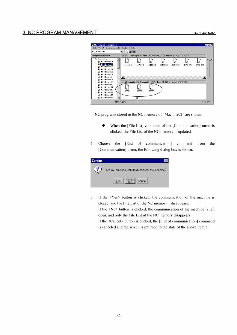
3. NC PROGRAM MANAGEMENT B-75044EN/02
-62-
NC programs stored in the NC memory of “Machine02” are shown.
� When the [File List] command of the [Communication] menu is
clicked, the File List of the NC memory is updated.
4 Choose the [End of communication] command from the
[Communication] menu, the following dialog box is shown.
5 If the <Yes> button is clicked, the communication of the machine is
closed, and the File List of the NC memory disappears.
If the <No> button is clicked, the communication of the machine is left
open, and only the File List of the NC memory disappears.
If the <Cancel> button is clicked, the [End of communication] command
is canceled and the screen is returned to the state of the above item 3.
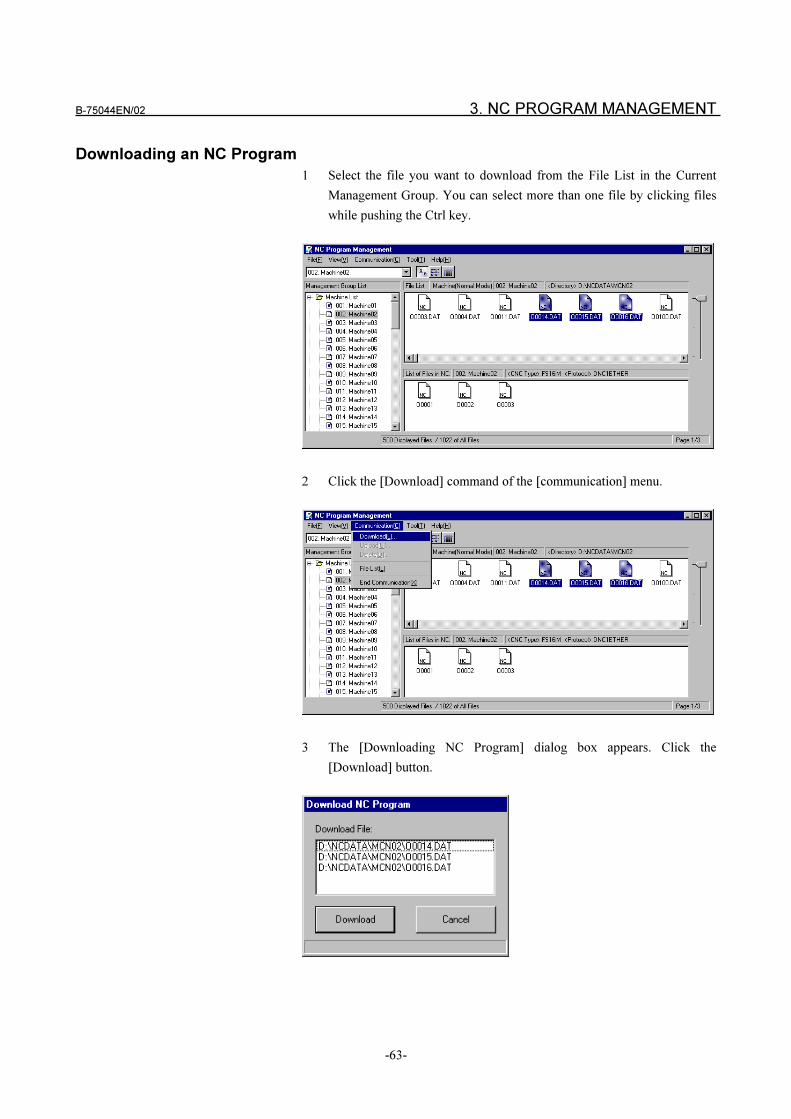
B-75044EN/02 3. NC PROGRAM MANAGEMENT
-63-
Downloading an NC Program
1 Select the file you want to download from the File List in the Current
Management Group. You can select more than one file by clicking files
while pushing the Ctrl key.
2 Click the [Download] command of the [communication] menu.
3 The [Downloading NC Program] dialog box appears. Click the
[Download] button.
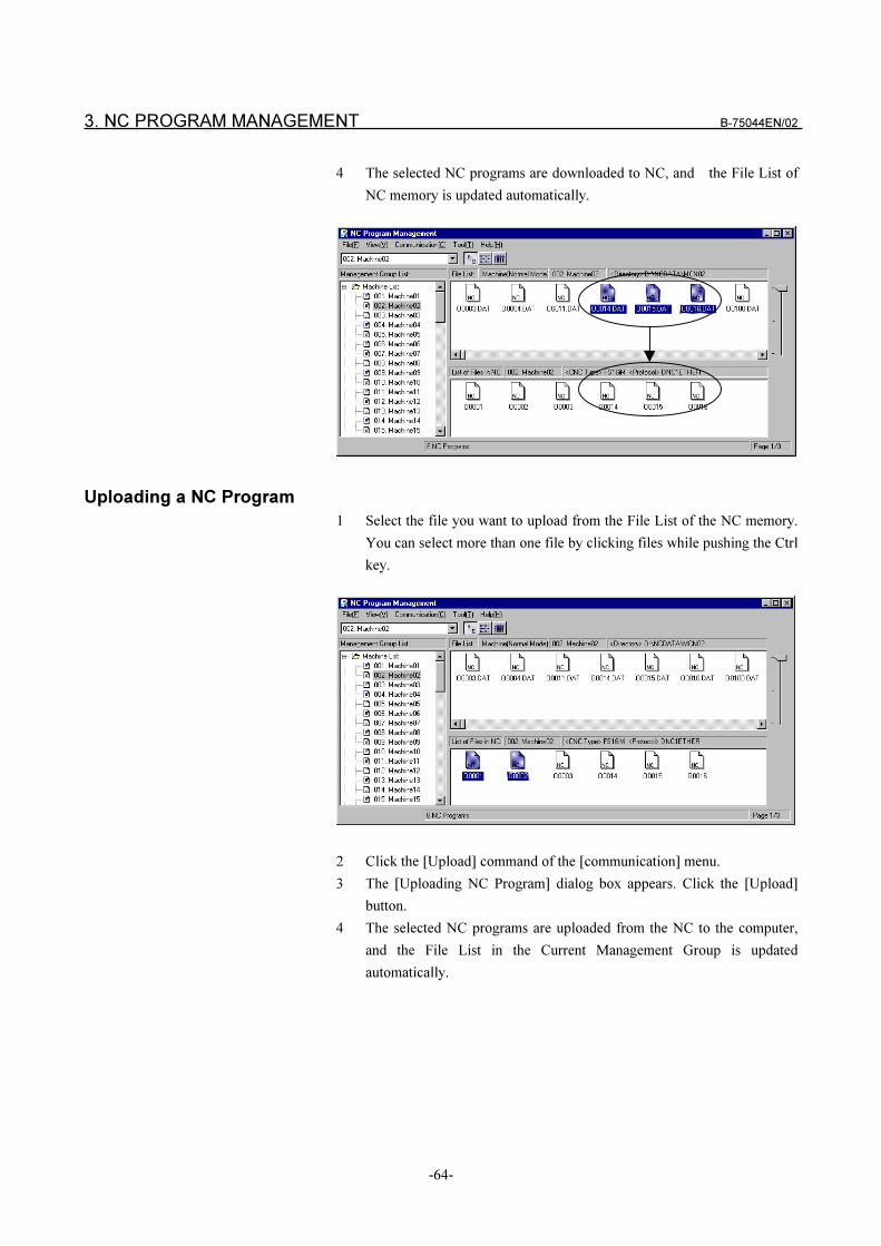
3. NC PROGRAM MANAGEMENT B-75044EN/02
-64-
4 The selected NC programs are downloaded to NC, and the File List of
NC memory is updated automatically.
Uploading a NC Program
1 Select the file you want to upload from the File List of the NC memory.
You can select more than one file by clicking files while pushing the Ctrl
key.
2 Click the [Upload] command of the [communication] menu.
3 The [Uploading NC Program] dialog box appears. Click the [Upload]
button.
4 The selected NC programs are uploaded from the NC to the computer,
and the File List in the Current Management Group is updated
automatically.
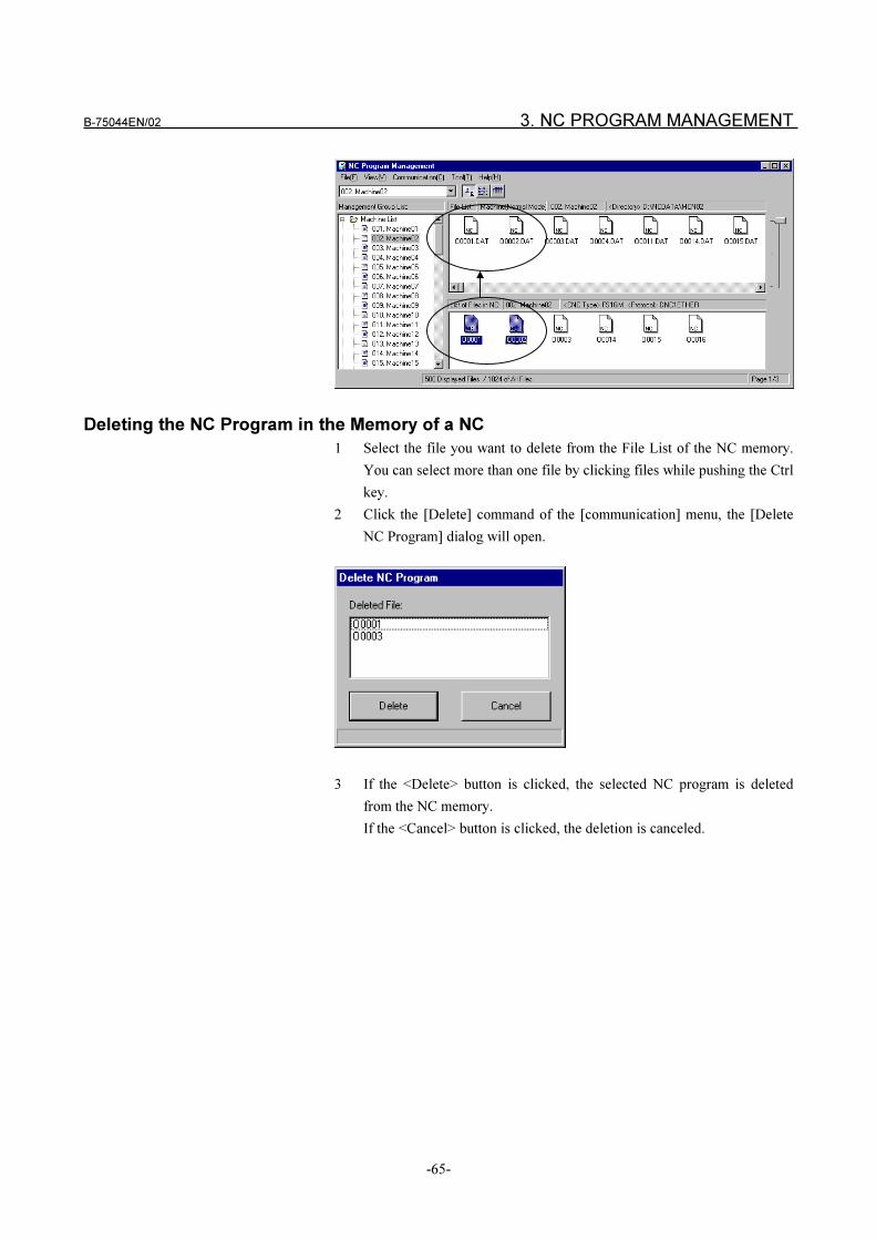
B-75044EN/02 3. NC PROGRAM MANAGEMENT
-65-
Deleting the NC Program in the Memory of a NC
1 Select the file you want to delete from the File List of the NC memory.
You can select more than one file by clicking files while pushing the Ctrl
key.
2 Click the [Delete] command of the [communication] menu, the [Delete
NC Program] dialog will open.
3 If the <Delete> button is clicked, the selected NC program is deleted
from the NC memory.
If the <Cancel> button is clicked, the deletion is canceled.
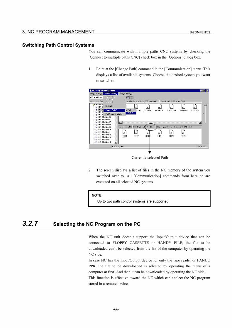
3. NC PROGRAM MANAGEMENT B-75044EN/02
-66-
Switching Path Control Systems
You can communicate with multiple paths CNC systems by checking the
[Connect to multiple paths CNC] check box in the [Options] dialog box.
1 Point at the [Change Path] command in the [Communication] menu. This
displays a list of available systems. Choose the desired system you want
to switch to.
2 The screen displays a list of files in the NC memory of the system you
switched over to. All [Communication] commands from here on are
executed on all selected NC systems.
3.2.7 Selecting the NC Program on the PC
When the NC unit doesn’t support the Input/Output device that can be
connected to FLOPPY CASSETTE or HANDY FILE, the file to be
downloaded can’t be selected from the list of the computer by operating the
NC side.
In case NC has the Input/Output device for only the tape reader or FANUC
PPR, the file to be downloaded is selected by operating the menu of a
computer at first. And then it can be downloaded by operating the NC side.
This function is effective toward the NC which can’t select the NC program
stored in a remote device.
Currently selected Path
NOTE
Up to two path control systems are supported.
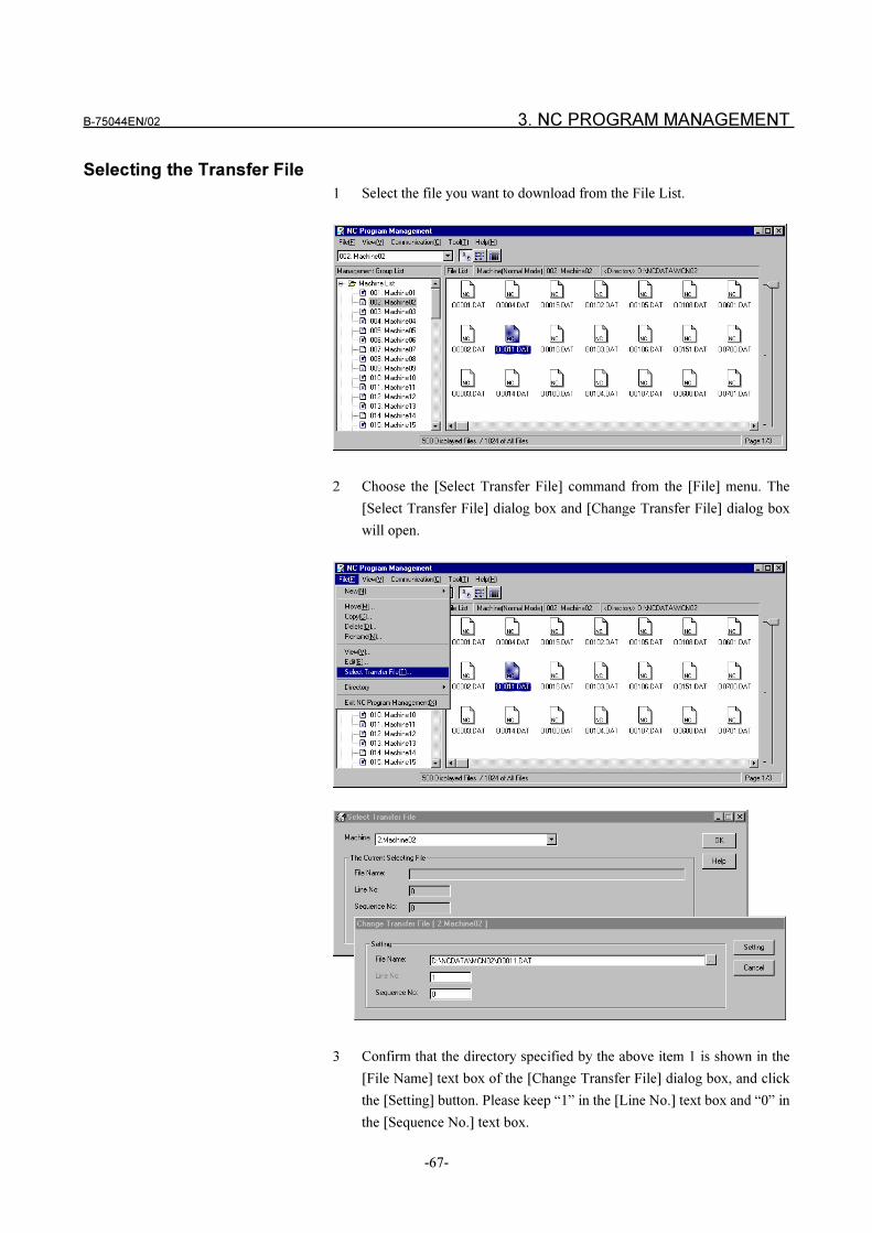
B-75044EN/02 3. NC PROGRAM MANAGEMENT
-67-
Selecting the Transfer File
1 Select the file you want to download from the File List.
2 Choose the [Select Transfer File] command from the [File] menu. The
[Select Transfer File] dialog box and [Change Transfer File] dialog box
will open.
3 Confirm that the directory specified by the above item 1 is shown in the
[File Name] text box of the [Change Transfer File] dialog box, and click
the [Setting] button. Please keep “1” in the [Line No.] text box and “0” in
the [Sequence No.] text box.
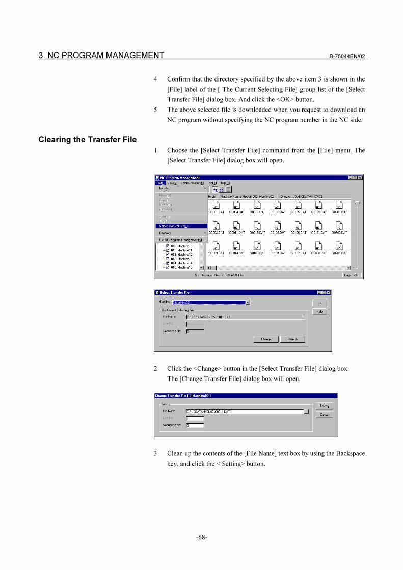
3. NC PROGRAM MANAGEMENT B-75044EN/02
-68-
4 Confirm that the directory specified by the above item 3 is shown in the
[File] label of the [ The Current Selecting File] group list of the [Select
Transfer File] dialog box. And click the <OK> button.
5 The above selected file is downloaded when you request to download an
NC program without specifying the NC program number in the NC side.
Clearing the Transfer File
1 Choose the [Select Transfer File] command from the [File] menu. The
[Select Transfer File] dialog box will open.
2 Click the <Change> button in the [Select Transfer File] dialog box.
The [Change Transfer File] dialog box will open.
3 Clean up the contents of the [File Name] text box by using the Backspace
key, and click the < Setting> button.
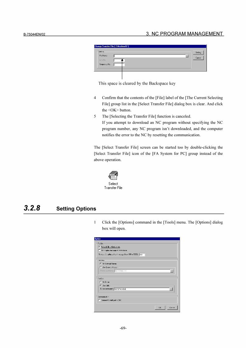
B-75044EN/02 3. NC PROGRAM MANAGEMENT
-69-
This space is cleared by the Backspace key
4 Confirm that the contents of the [File] label of the [The Current Selecting
File] group list in the [Select Transfer File] dialog box is clear. And click
the <OK> button.
5 The [Selecting the Transfer File] function is canceled.
If you attempt to download an NC program without specifying the NC
program number, any NC program isn’t downloaded, and the computer
notifies the error to the NC by resetting the communication.
The [Select Transfer File] screen can be started too by double-clicking the
[Select Transfer File] icon of the [FA System for PC] group instead of the
above operation.
3.2.8 Setting Options
1 Click the [Options] command in the [Tools] menu. The [Options] dialog
box will open.
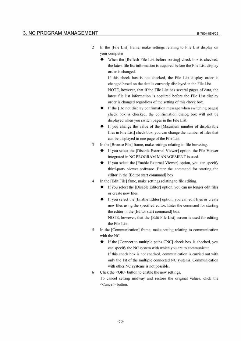
3. NC PROGRAM MANAGEMENT B-75044EN/02
-70-
2 In the [File List] frame, make settings relating to File List display on
your computer.
� When the [Reflesh File List before sorting] check box is checked,
the latest file list information is acquired before the File List display
order is changed.
If this check box is not checked, the File List display order is
changed based on the details currently displayed in the File List.
NOTE, however, that if the File List has several pages of data, the
latest file list information is acquired before the File List display
order is changed regardless of the setting of this check box.
� If the [Do not display confirmation message when switching pages]
check box is checked, the confirmation dialog box will not be
displayed when you switch pages in the File List.
� If you change the value of the [Maximum number of displayable
files in File List] check box, you can change the number of files that
can be displayed in one page of the File List.
3 In the [Browse File] frame, make settings relating to file browsing.
� If you select the [Disable External Viewer] option, the File Viewer
integrated in NC PROGRAM MANAGEMENT is used.
� If you select the [Enable External Viewer] option, you can specify
third-party viewer software. Enter the command for starting the
editor in the [Editor start command] box.
4 In the [Edit File] fame, make settings relating to file editing.
� If you select the [Disable Editor] option, you can no longer edit files
or create new files.
� If you select the [Enable Editor] option, you can edit files or create
new files using the specified editor. Enter the command for starting
the editor in the [Editor start command] box.
NOTE, however, that the [Edit File List] screen is used for editing
the File List.
5 In the [Communication] frame, make setting relating to communication
with the NC.
� If the [Connect to multiple paths CNC] check box is checked, you
can specify the NC system with which you are to communicate.
If this check box is not checked, communication is carried out with
only the 1st of the multiple connected NC systems. Communication
with other NC systems is not possible.
6 Click the <OK> button to enable the new settings.
To cancel setting midway and restore the original values, click the
<Cancel> button.

B-75044EN/02 4. FA LIBRARY
-71-
4 FA LIBRARY
4. FA LIBRARY B-75044EN/02
-72-
4.1 OUTLINE
This chapter describes the user interface of the functions supported by FA
LIBRARY of FA SYSTEM for PC.
4.1.1 Service Type
FA LIBRARY is composed of “System service”, “Request service”, and
“Diagnosis and other services”.
“System service” is the function group for handling the system such as the
start and end of the communication process.
“Request service” is the function group for handling NC such as the download
of an NC program. All functions for “System service” are processed
synchronously. But for “Request service”, two types of functions are
provided; synchronous functions and asynchronous functions.
An asynchronous and a synchronous functions are different in the timing when
the called function returns the control to an application program.
A synchronous function waits until FA SYSTEM for PC finishes the request,
and returns its result.
Though, an asynchronous function sends a request and returns the control to
an application program at once without waiting for the result. The result can
be checked by the other function.
For example, the F_DownloadFileNumber function, which downloads an
NC program, doesn’t return until the download is finished (synchronous
treatment).
The F_DownloadFileNumberEx function requests the system to
download an NC program, and returns at once. The return value is the
descriptor ID which can be used to get the result.
When an application program calls the F_Response function with the
descriptor ID as an argument, it can be confirmed whether the download is
finished. And if so, the result indicates that the download was successful or
not.
If an asynchronous function is used, one application program can handle more
than one service at the same time because each asynchronous function doesn’t
wait for the result.
When you use “System service” or “Request service”, you must judge the
result. In such case, there are some useful functions like F_Response in the
function group of “Diagnosis and other services”.
For details on the log library, refer to "4.5 Log Library."
B-75044EN/02 4. FA LIBRARY
-73-
4.1.2 How to Read the Library Function
The functions are classified according to the service group explained in “4.2
System service”, “4.3 Request service”, and “4.4 Diagnosis and other
services” and “4.5 Log Service”.
As for “System service”, the most application program can be satisfied with
the functions of only Clause 4.2.
Almost all application specifications can be satisfied by only the functions of
clauses 4.2.1 and 4.2.2. Refer to clauses 4.2.3 to 4.2.12 if necessary.
As for “Request service”, refer to the function in accordance with the
specification of your application.
For details on “Diagnostics and Other Services”, be sure to read about the
functions in clauses 4.4.1, 4.4.6 and 4.4.7. Refer to other clauses if necessary
when these functions appear in the explanation of the function you use.
Every function is explained by the items of SYNOPSIS, DESCRIPTION, and
RETURN VALUE.
SYNOPSIS describes the calling form of function. In case of VC++, F_ is
given to the top of the function name. F_ isn’t stuck to the function for VB.
The contents of DESCRIPTION and RETURN VALUE are common with the
function for VB and VC++.
When you develop the application program with VB, regard the function
name described in explanation as the name without F_.
Some functions have the argument of the tool post number.
In case of the multipath NC which has several tool posts, the tool post number
indicates which tool post should comply with the request .
As for DNC2, be sure to set up the value of “0” because the tool post number
can’t be used.
As for DNC1 or DNC1/Ethernet, set the value of “1” in case of the first tool
post. And set “2” in case of the second tool post.
All functions of FA LIBRARY can be used for the NC connected with DNC1,
DNC2 and DNC1/Ethernet, except for a special mention.
4. FA LIBRARY B-75044EN/02
-74-
4.1.3 About the Development Language of the Application Program
The functions can be called from both of Microsoft Visual Basic Ver4.0(VB)
and Microsoft Visual C++ Ver4.0(VC++). (For details on VB and VC++
versions, refer to "2.1 Computer Operating Environment.")
In case of Visual Basic
In case of VB, the user interface is provided with “OLE Automation”. So,
“Object” is created by the CreateObject() function, and the service can be
requested by calling “Method” of “Object”. “FanucCom.Library” must be
specified when “Object” is created by CreateObject().
Dim Obj As Object
Dim Rtn As Boolean
Set Obj = CreateObject(“FanucCom.Library”)
Rtn = Obj.Begin
Rtn = Obj.CreateCommunication
When FA LIBRARY is installed, “FanucCom.Library” is registered
automatically to “Registry” in WindowsNT as “OLE Automation”.
In case of VC++
In case of C++, the user interface is provided with “DLL”. “Class” of C++ is
not used for user interface. Therefore, each function is called directly.
BOOL Rtn;
Rtn = F_Begin();
Rtn = F_CreateCommunication();
In case of the library for C++, F_ is stuck to the top of a function name. This
character indicates that the function is provided by FANUC.
When you make an application program, the following files are used.
� The file which must be included while an application program is
compiled.
INCLUDE FComLib.h
� The library modules which must be combined while an application
program is linked
LIB FComLib.lib (for release)
LIB FComLibD.lib (for debug)
LIB LogLib.lib (for release)
LIB LogLibD.lib (for debug)
B-75044EN/02 4. FA LIBRARY
-75-
� The DLL files which are referred while an application program is
running
BIN FComLib.dll (for release)
BIN FComLibD.dll (for debug)
BIN LogLib.dll (for release)
BIN LogLibD.dll (for debug)
The above relative directories are continued from the directory where FA
LIBRARY is installed.
When an application program is compiled by using VC++, both of a debug
and a release version module are created.
The debug version module includes the debug information; the memory
utilization, the records of tracing the control and so on. The release version
module doesn’t include these information.
To develop an application program, debug the program in a debug version at
first, and then check it with a release version. Though the program must be
checked for both of a debug and a release version, these two processes make
the quality program, and these efforts should be resulted in efficiency.
By reason of VC++ descriptions, if a program is consisted of a debug and a
release version modules, it doesn’t work correctly.
FA LIBRARY provides two modules; the debug and the release versions.
When you develop the application with a debug version, please use the
debug version library . And use the release version library when you make up
an application program of a release version.
4.1.4 About Starting Applications You Have Developed
Pay attention to the following when starting applications made using this
library. Let's assume that the application made by the user is named
“YourApp.exe” and that the directory in which FA SYSTEM for PC is “C:
FpFaSys”.
In case of Visual Basic
“YourApp.exe” starts whichever directory it is on.
In case of Visual C++
Place “YourApp.exe” in “C: FpFaSys”. If you place it in a different
directory, add the path for pointing C: FpFaSys Bin to the system variable
“PATH”. To set system variable “PATH” by starting [System] in the [Control
Panel] and set in [Setup]. The library for VC++ is DLL, and these are stored
to “C: FpFaSys Bin”. So, that location must be set to the OS.
4. FA LIBRARY B-75044EN/02
-76-
4.1.5 About Sample Program
Sample programs are appended in the package of FA LIBRARY. These
sample programs are made up of the FA LIBRARY functions described in
Section 4.2 to 4.5.
Files and Directories
There are two sample programs made by using VC++(version 4.0) and VB
(version 4.0).
The two sample programs have the same operation and menu layout.
The executable and the source files of the two programs are placed in the
following directories.
Type of program executable file source file
VC++ BIN FComTst.exe SAMPLE FComTst *.*
VB BIN FComTVB.exe SAMPLE FComTVB *.*
The above relative directories are continued from the directory where FA
LIBRARY is installed.
The following table shows the compatibility between FA LIBRARY functions
and each communication protocol, and a list of sample files used by these
functions.
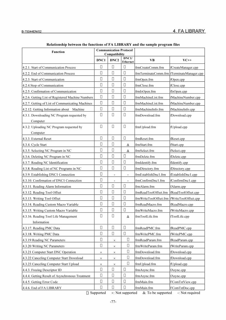
B-75044EN/02 4. FA LIBRARY
-77-
Relationship between the functions of FA LIBRARY and the sample program files
Communication Protocol
CompatibilityFunction
DNC1 DNC2DNC1/
EthernetVB VC++
4.2.1. Start of Communication Process � � � frmCreateComm.frm fCreateManager.cpp
4.2.2. End of Communication Process � � � frmTerminateComm.frm fTerminateManager.cpp
4.2.3. Start of Communication � � � frmOpen.frm fOpen.cpp
4.2.4.Stop of Communication � � � frmClose.frm fClose.cpp
4.2.5. Confirmation of Communication � � � frmIsOpen.frm fIsOpen.cpp
4.2.6. Getting List of Registered Machine Numbers � � � frmMachineList.frm fMachineNumber.cpp
4.2.7. Getting of List of Communicating Machines � � � frmMachineList.frm fMachineNumber.cpp
4.2.12. Getting Information about Machine � � � frmMachineInfo.frm fMachineInfo.cpp
4.3.1. Downloading NC Program requested by
Computer
� � � frmDownload.frm fDownload.cpp
4.3.2. Uploading NC Program requested by
Computer
� � � frmUpload.frm fUpload.cpp
4.3.3. External Reset � � � frmReset.frm fReset.cpp
4.3.4. Cycle Start � � ∆ frmStart.frm fStart.cpp
4.3.5. Selecting NC Program in NC � � ∆ frmSelect.frm fSelect.cpp
4.3.6. Deleting NC Program in NC � � � frmDelete.frm fDelete.cpp
4.3.7. Reading NC Identification � � � frmIdentify.frm fIdentify.cpp
4.3.8. Reading List of NC Programs in NC � � � frmDirectory.frm fDirectory.cpp
4.3.9. Establishing DNC1 Connection � - - frmEstablishDnc1.frm fEstablishDnc1.cpp
4.3.10. Confirmation of DNC1 Connection � - - frmConfirmDnc1.frm fConfirmDnc1.cpp
4.3.11. Reading Alarm Information � � � frmAlarm.frm fAlarm.cpp
4.3.12. Reading Tool Offset � � � frmReadToolOffset.frm fReadToolOffset.cpp
4.3.13. Writing Tool Offset � � � frmWriteToolOffset.frm fWriteToolOffset.cpp
4.3.14. Reading Custom Macro Variable � � � frmReadMacro.frm fReadMacro.cpp
4.3.15. Writing Custom Macro Variable � � � frmWriteMacro.frm fWriteMacro.cpp
4.3.16. Reading Tool Life Management
Information
� � ∆ frmToolLife.frm fToolLife.cpp
4.3.17. Reading PMC Data � � � frmReadPMC.frm fReadPMC.cpp
4.3.18. Writing PMC Data � � � frmWritePMC.frm fWritePMC.cpp
4.3.19 Reading NC Parameters ��
� frmReadParam.frm fReadParam.cpp
4.3.20 Writing NC Parameters ��
� frmWriteParam.frm fWriteParam.cpp
4.3.21 Computer Start DNC Operation � �� frmDownload.frm fDownload.cpp
4.3.22 Canceling Computer Start Download � �� frmDownload.frm fDownload.cpp
4.3.23 Canceling Computer Start Upload � �� frmUpload.frm fUpload.cpp
4.4.3. Freeing Descriptor ID � � � frmAsync.frm fAsync.cpp
4.4.4. Getting Result of Asynchronous Treatment � � � frmAsync.frm fAsync.cpp
4.4.5. Getting Error Code � � � frmMain.frm FComTstView.cpp
4.4.6. End of FA LIBRARY � � � frmMain.frm FComTstDoc.cpp
� : Supported �: Not supported ∆: To be supported -: Not required
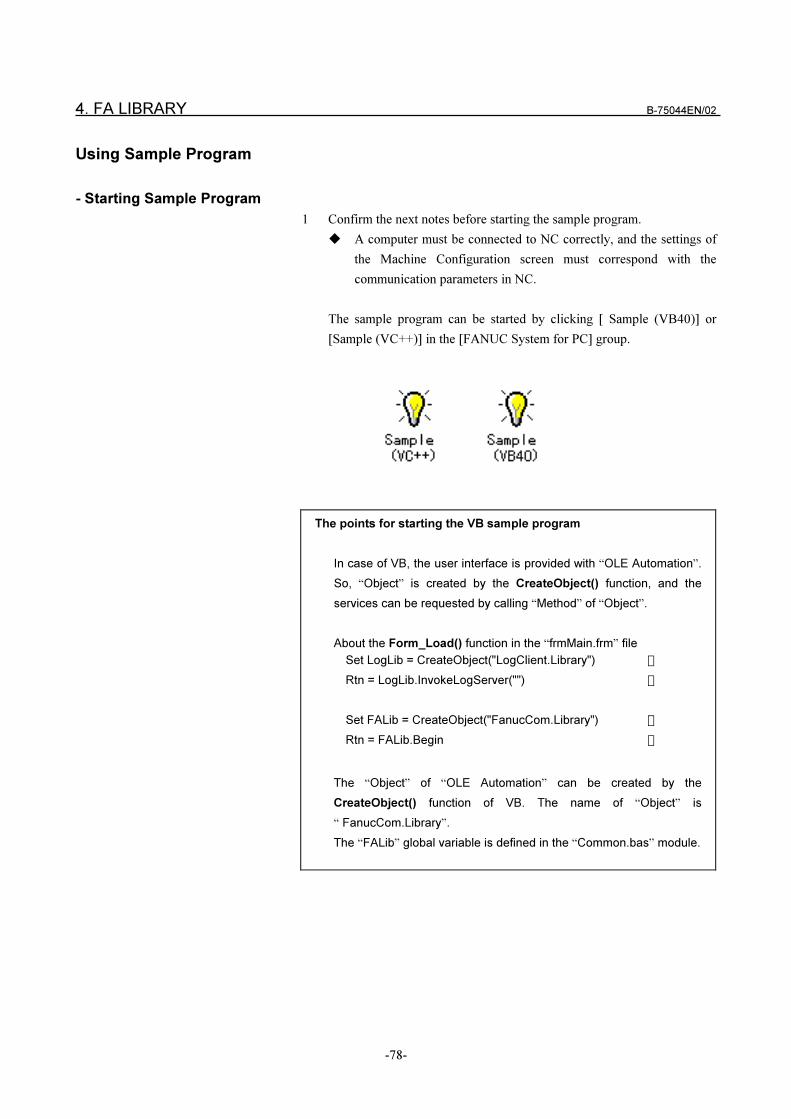
4. FA LIBRARY B-75044EN/02
-78-
Using Sample Program
- Starting Sample Program
1 Confirm the next notes before starting the sample program.
� A computer must be connected to NC correctly, and the settings of
the Machine Configuration screen must correspond with the
communication parameters in NC.
The sample program can be started by clicking [ Sample (VB40)] or
[Sample (VC++)] in the [FANUC System for PC] group.
The points for starting the VB sample program
In case of VB, the user interface is provided with “OLE Automation”.
So, “Object” is created by the CreateObject() function, and the
services can be requested by calling “Method” of “Object”.
About the Form_Load() function in the “frmMain.frm” file
Set LogLib = CreateObject("LogClient.Library") �
Rtn = LogLib.InvokeLogServer("") �
Set FALib = CreateObject("FanucCom.Library") �
Rtn = FALib.Begin �
The “Object” of “OLE Automation” can be created by the
CreateObject() function of VB. The name of “Object” is
“ FanucCom.Library”.
The “FALib” global variable is defined in the “Common.bas” module.
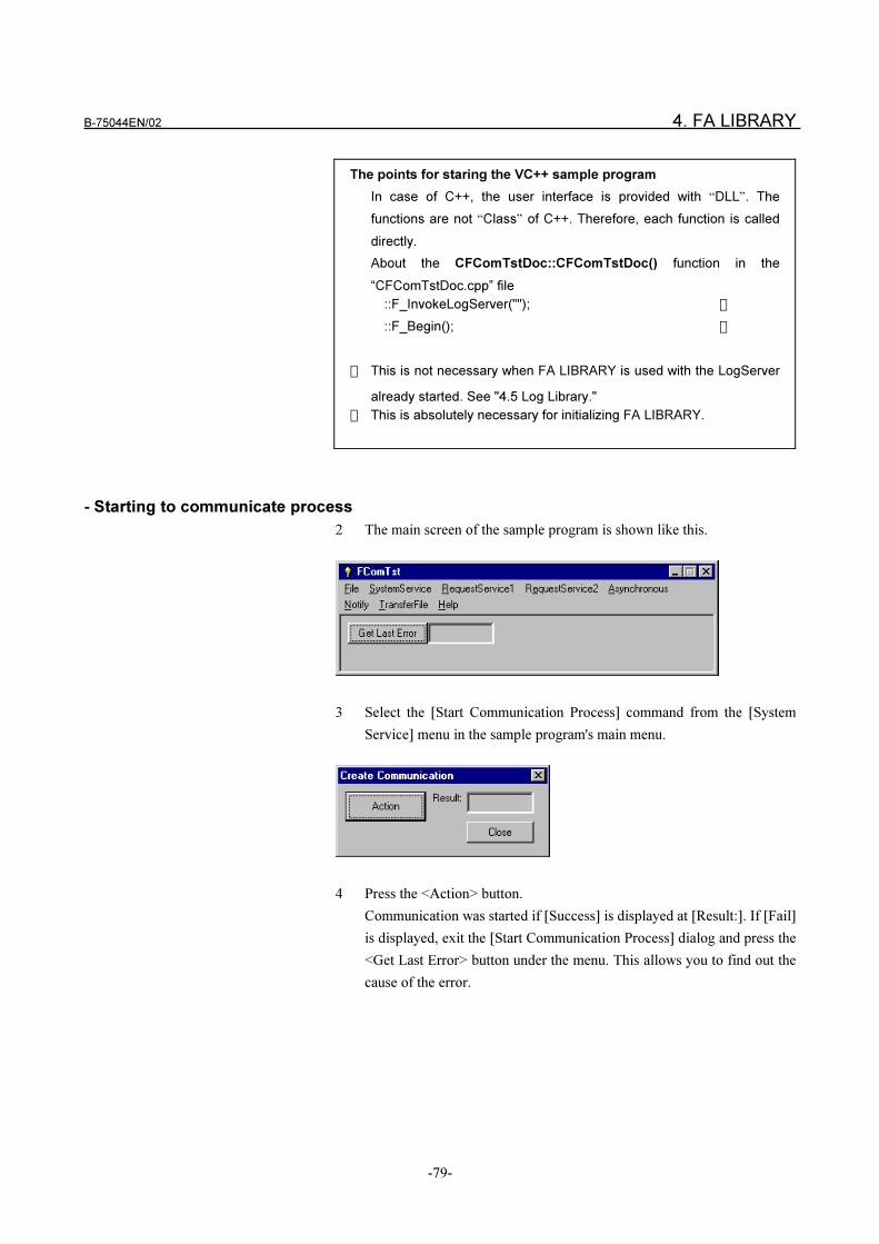
B-75044EN/02 4. FA LIBRARY
-79-
The points for staring the VC++ sample program
In case of C++, the user interface is provided with “DLL”. The
functions are not “Class” of C++. Therefore, each function is called
directly.
About the CFComTstDoc::CFComTstDoc() function in the
“CFComTstDoc.cpp” file
::F_InvokeLogServer(""); �
::F_Begin(); �
� This is not necessary when FA LIBRARY is used with the LogServer
already started. See "4.5 Log Library."
� This is absolutely necessary for initializing FA LIBRARY.
- Starting to communicate process
2 The main screen of the sample program is shown like this.
3 Select the [Start Communication Process] command from the [System
Service] menu in the sample program's main menu.
4 Press the <Action> button.
Communication was started if [Success] is displayed at [Result:]. If [Fail]
is displayed, exit the [Start Communication Process] dialog and press the
<Get Last Error> button under the menu. This allows you to find out the
cause of the error.
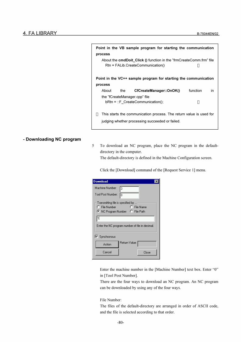
4. FA LIBRARY B-75044EN/02
-80-
Point in the VB sample program for starting the communication
process
About the cmdDoit_Click () function in the ”frmCreateComm.frm” file
Rtn = FALib.CreateCommunication() �
Point in the VC++ sample program for starting the communication
process
About the CfCreateManager::OnOK() function in
the ”fCreateManager.cpp” file
bRtn = ::F_CreateCommunication(); �
� This starts the communication process. The return value is used for
judging whether processing succeeded or failed.
- Downloading NC program
5 To download an NC program, place the NC program in the default-
directory in the computer.
The default-directory is defined in the Machine Configuration screen.
Click the [Download] command of the [Request Service 1] menu.
Enter the machine number in the [Machine Number] text box. Enter “0”
in [Tool Post Number].
There are the four ways to download an NC program. An NC program
can be downloaded by using any of the four ways.
File Number:
The files of the default-directory are arranged in order of ASCII code,
and the file is selected according to that order.
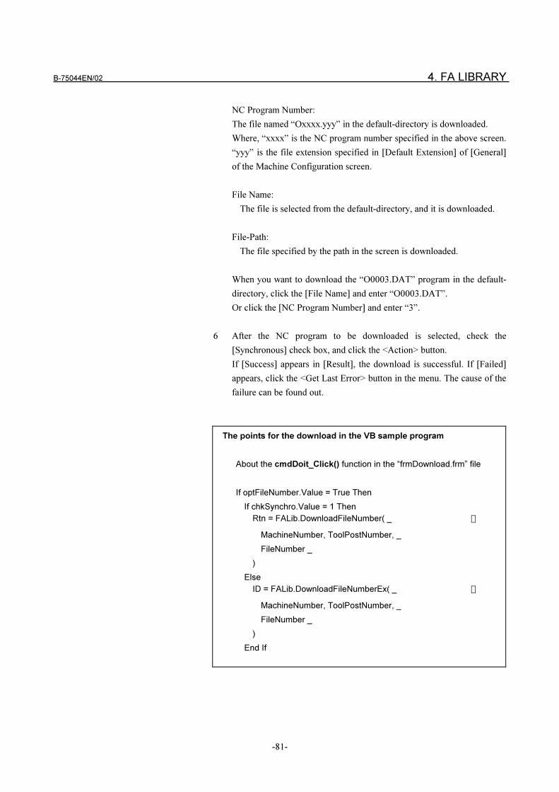
B-75044EN/02 4. FA LIBRARY
-81-
NC Program Number:
The file named “Oxxxx.yyy” in the default-directory is downloaded.
Where, “xxxx” is the NC program number specified in the above screen.
“yyy” is the file extension specified in [Default Extension] of [General]
of the Machine Configuration screen.
File Name:
The file is selected from the default-directory, and it is downloaded.
File-Path:
The file specified by the path in the screen is downloaded.
When you want to download the “O0003.DAT” program in the default-
directory, click the [File Name] and enter “O0003.DAT”.
Or click the [NC Program Number] and enter “3”.
6 After the NC program to be downloaded is selected, check the
[Synchronous] check box, and click the <Action> button.
If [Success] appears in [Result], the download is successful. If [Failed]
appears, click the <Get Last Error> button in the menu. The cause of the
failure can be found out.
The points for the download in the VB sample program
About the cmdDoit_Click() function in the “frmDownload.frm” file
If optFileNumber.Value = True Then
If chkSynchro.Value = 1 Then
Rtn = FALib.DownloadFileNumber( _ �
MachineNumber, ToolPostNumber, _
FileNumber _
)
Else
ID = FALib.DownloadFileNumberEx( _ �
MachineNumber, ToolPostNumber, _
FileNumber _
)
End If
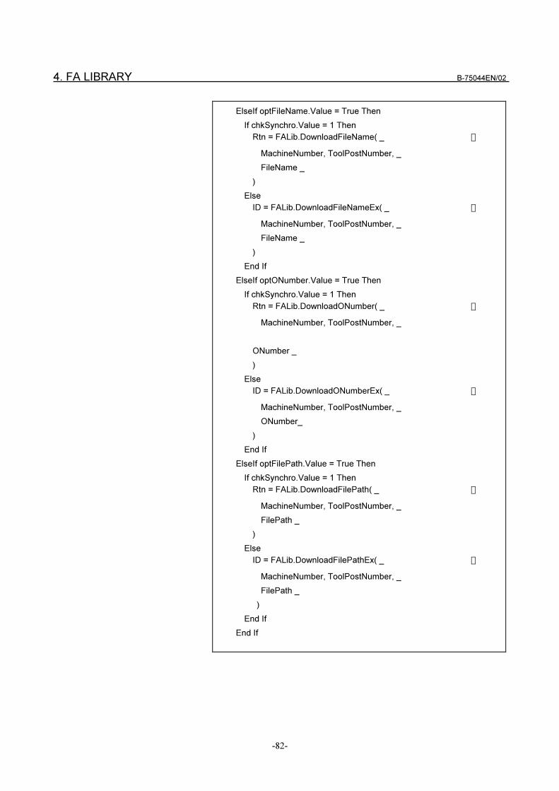
4. FA LIBRARY B-75044EN/02
-82-
ElseIf optFileName.Value = True Then
If chkSynchro.Value = 1 Then
Rtn = FALib.DownloadFileName( _ �
MachineNumber, ToolPostNumber, _
FileName _
)
Else
ID = FALib.DownloadFileNameEx( _ �
MachineNumber, ToolPostNumber, _
FileName _
)
End If
ElseIf optONumber.Value = True Then
If chkSynchro.Value = 1 Then
Rtn = FALib.DownloadONumber( _ �
MachineNumber, ToolPostNumber, _
ONumber _
)
Else
ID = FALib.DownloadONumberEx( _ �
MachineNumber, ToolPostNumber, _
ONumber_
)
End If
ElseIf optFilePath.Value = True Then
If chkSynchro.Value = 1 Then
Rtn = FALib.DownloadFilePath( _ �
MachineNumber, ToolPostNumber, _
FilePath _
)
Else
ID = FALib.DownloadFilePathEx( _ �
MachineNumber, ToolPostNumber, _
FilePath _
)
End If
End If
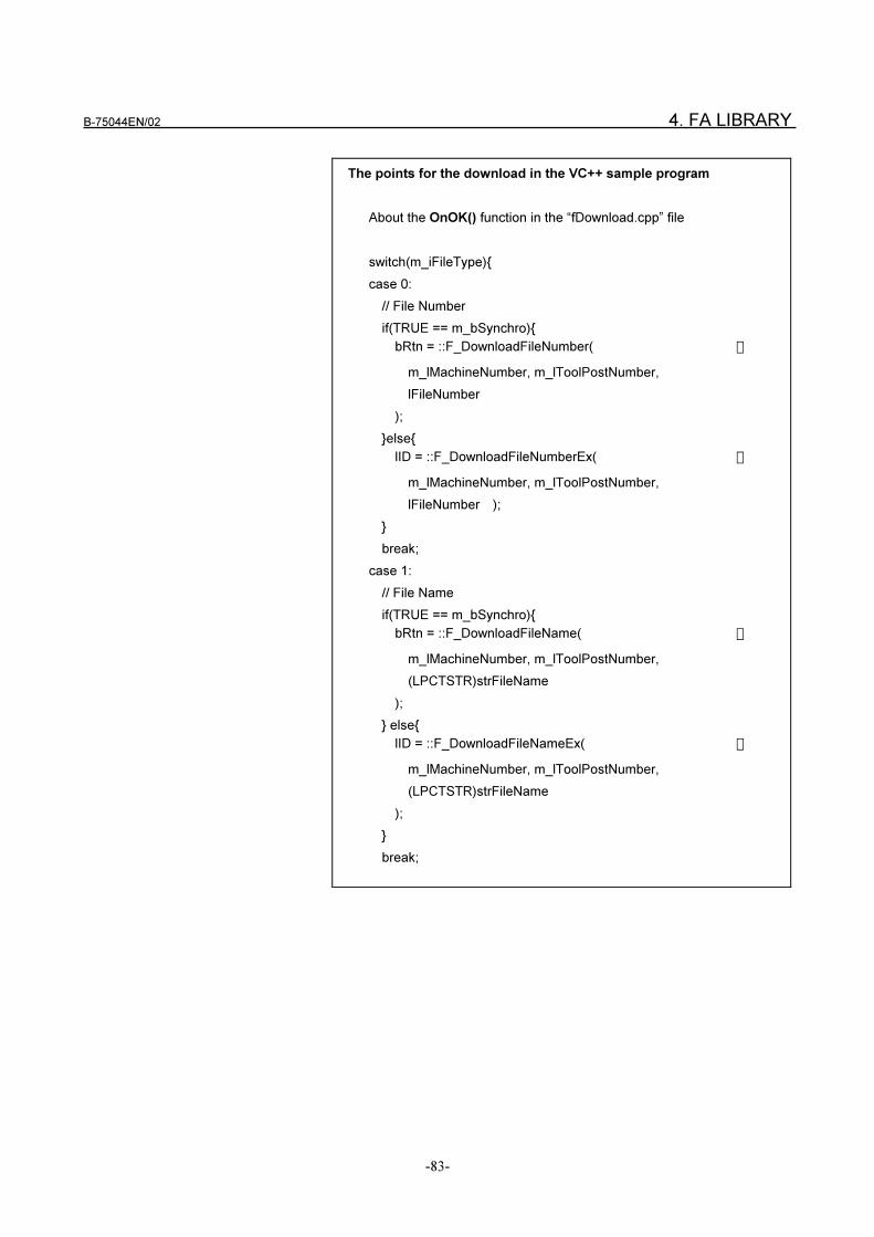
B-75044EN/02 4. FA LIBRARY
-83-
The points for the download in the VC++ sample program
About the OnOK() function in the “fDownload.cpp” file
switch(m_iFileType){
case 0:
// File Number
if(TRUE == m_bSynchro){
bRtn = ::F_DownloadFileNumber( �
m_lMachineNumber, m_lToolPostNumber,
lFileNumber
);
}else{
lID = ::F_DownloadFileNumberEx( �
m_lMachineNumber, m_lToolPostNumber,
lFileNumber );
}
break;
case 1:
// File Name
if(TRUE == m_bSynchro){
bRtn = ::F_DownloadFileName( �
m_lMachineNumber, m_lToolPostNumber,
(LPCTSTR)strFileName
);
} else{
lID = ::F_DownloadFileNameEx( �
m_lMachineNumber, m_lToolPostNumber,
(LPCTSTR)strFileName
);
}
break;
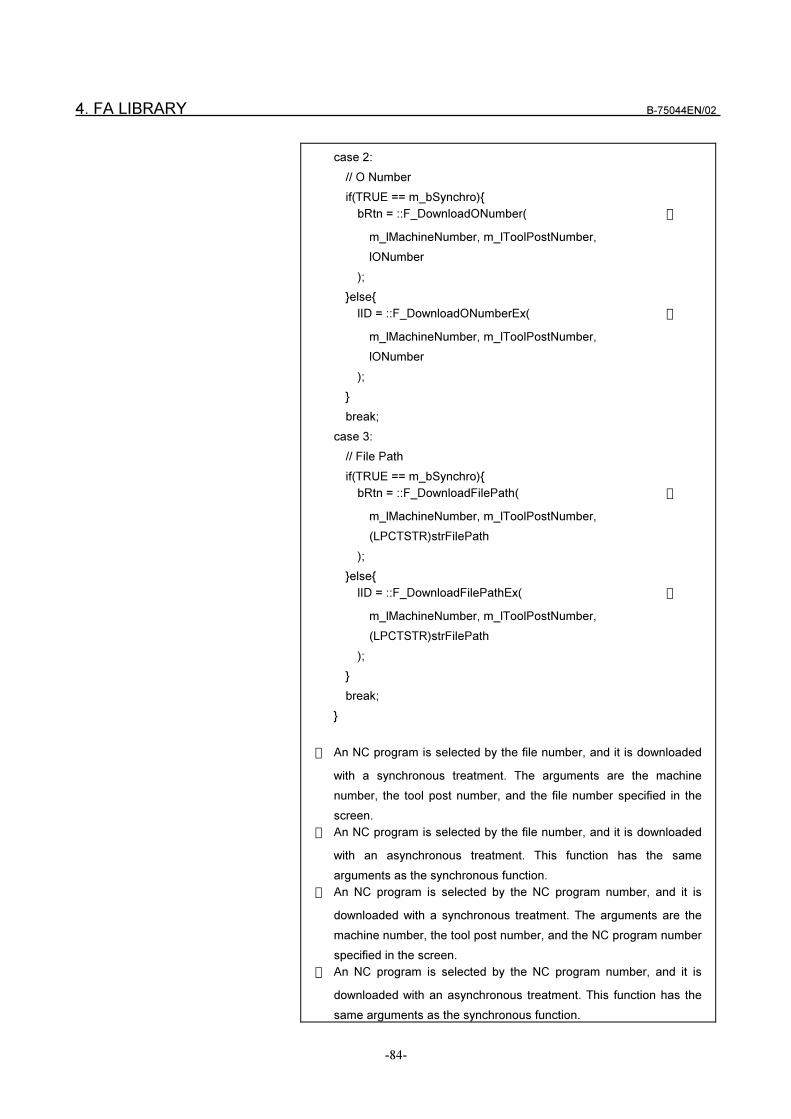
4. FA LIBRARY B-75044EN/02
-84-
case 2:
// O Number
if(TRUE == m_bSynchro){
bRtn = ::F_DownloadONumber( �
m_lMachineNumber, m_lToolPostNumber,
lONumber
);
}else{
lID = ::F_DownloadONumberEx( �
m_lMachineNumber, m_lToolPostNumber,
lONumber
);
}
break;
case 3:
// File Path
if(TRUE == m_bSynchro){
bRtn = ::F_DownloadFilePath( �
m_lMachineNumber, m_lToolPostNumber,
(LPCTSTR)strFilePath
);
}else{
lID = ::F_DownloadFilePathEx( �
m_lMachineNumber, m_lToolPostNumber,
(LPCTSTR)strFilePath
);
}
break;
}
� An NC program is selected by the file number, and it is downloaded
with a synchronous treatment. The arguments are the machine
number, the tool post number, and the file number specified in the
screen.
� An NC program is selected by the file number, and it is downloaded
with an asynchronous treatment. This function has the same
arguments as the synchronous function.
� An NC program is selected by the NC program number, and it is
downloaded with a synchronous treatment. The arguments are the
machine number, the tool post number, and the NC program number
specified in the screen.
� An NC program is selected by the NC program number, and it is
downloaded with an asynchronous treatment. This function has the
same arguments as the synchronous function.
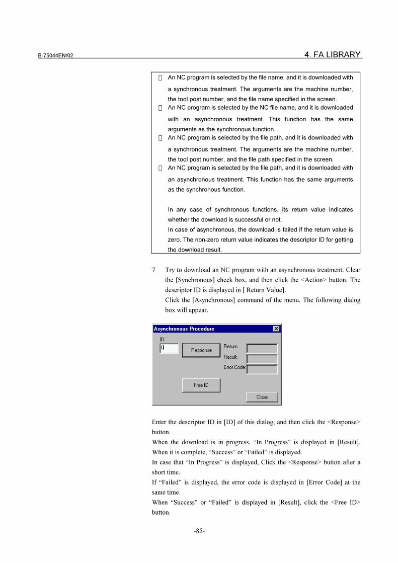
B-75044EN/02 4. FA LIBRARY
-85-
� An NC program is selected by the file name, and it is downloaded with
a synchronous treatment. The arguments are the machine number,
the tool post number, and the file name specified in the screen.
� An NC program is selected by the NC file name, and it is downloaded
with an asynchronous treatment. This function has the same
arguments as the synchronous function.
� An NC program is selected by the file path, and it is downloaded with
a synchronous treatment. The arguments are the machine number,
the tool post number, and the file path specified in the screen.
� An NC program is selected by the file path, and it is downloaded with
an asynchronous treatment. This function has the same arguments
as the synchronous function.
In any case of synchronous functions, its return value indicates
whether the download is successful or not.
In case of asynchronous, the download is failed if the return value is
zero. The non-zero return value indicates the descriptor ID for getting
the download result.
7 Try to download an NC program with an asynchronous treatment. Clear
the [Synchronous] check box, and then click the <Action> button. The
descriptor ID is displayed in [ Return Value].
Click the [Asynchronous] command of the menu. The following dialog
box will appear.
Enter the descriptor ID in [ID] of this dialog, and then click the <Response>
button.
When the download is in progress, “In Progress” is displayed in [Result].
When it is complete, “Success” or “Failed” is displayed.
In case that “In Progress” is displayed, Click the <Response> button after a
short time.
If “Failed” is displayed, the error code is displayed in [Error Code] at the
same time.
When “Success” or “Failed” is displayed in [Result], click the <Free ID>
button.
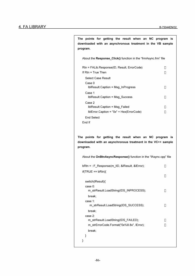
4. FA LIBRARY B-75044EN/02
-86-
The points for getting the result when an NC program is
downloaded with an asynchronous treatment in the VB sample
program.
About the Response_Click() function in the “frmAsync.frm” file
Rtn = FALib.Response(ID, Result, ErrorCode) �
If Rtn = True Then �
Select Case Result
Case 0
lblResult.Caption = Msg_InProgress �
Case 1
lblResult.Caption = Msg_Success �
Case 2
lblResult.Caption = Msg_Failed �
lblError.Caption = "0x" + Hex(ErrorCode) �
End Select
End If
The points for getting the result when an NC program is
downloaded with an asynchronous treatment in the VC++ sample
program.
About the OnBtnAsyncResponse() function in the “fAsync.cpp” file
bRtn = ::F_Response(m_lID, &lResult, &lError); �
if(TRUE == bRtn){
�
switch(lResult){
case 0:
m_strResult.LoadString(IDS_INPROCESS); �
break;
case 1:
m_strResult.LoadString(IDS_SUCCESS); �
break;
case 2:
m_strResult.LoadString(IDS_FAILED); �
m_strErrorCode.Format("0x%8.8x", lError); �
break;
}
}
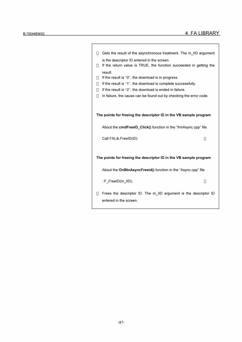
B-75044EN/02 4. FA LIBRARY
-87-
� Gets the result of the asynchronous treatment. The m_IID argument
is the descriptor ID entered in the screen.
� If the return value is TRUE, the function succeeded in getting the
result.
� If the result is “0”, the download is in progress.
� If the result is “1”, the download is complete successfully.
� If the result is “2”, the download is ended in failure.
� In failure, the cause can be found out by checking the error code.
The points for freeing the descriptor ID in the VB sample program
About the cmdFreeID_Click() function in the “frmAsync.cpp” file
Call FALib.FreeID(ID) �
The points for freeing the descriptor ID in the VB sample program
About the OnBtnAsyncFreeid() function in the “Async.cpp” file
::F_FreeID(m_lID); �
� Frees the descriptor ID. The m_IID argument is the descriptor ID
entered in the screen.
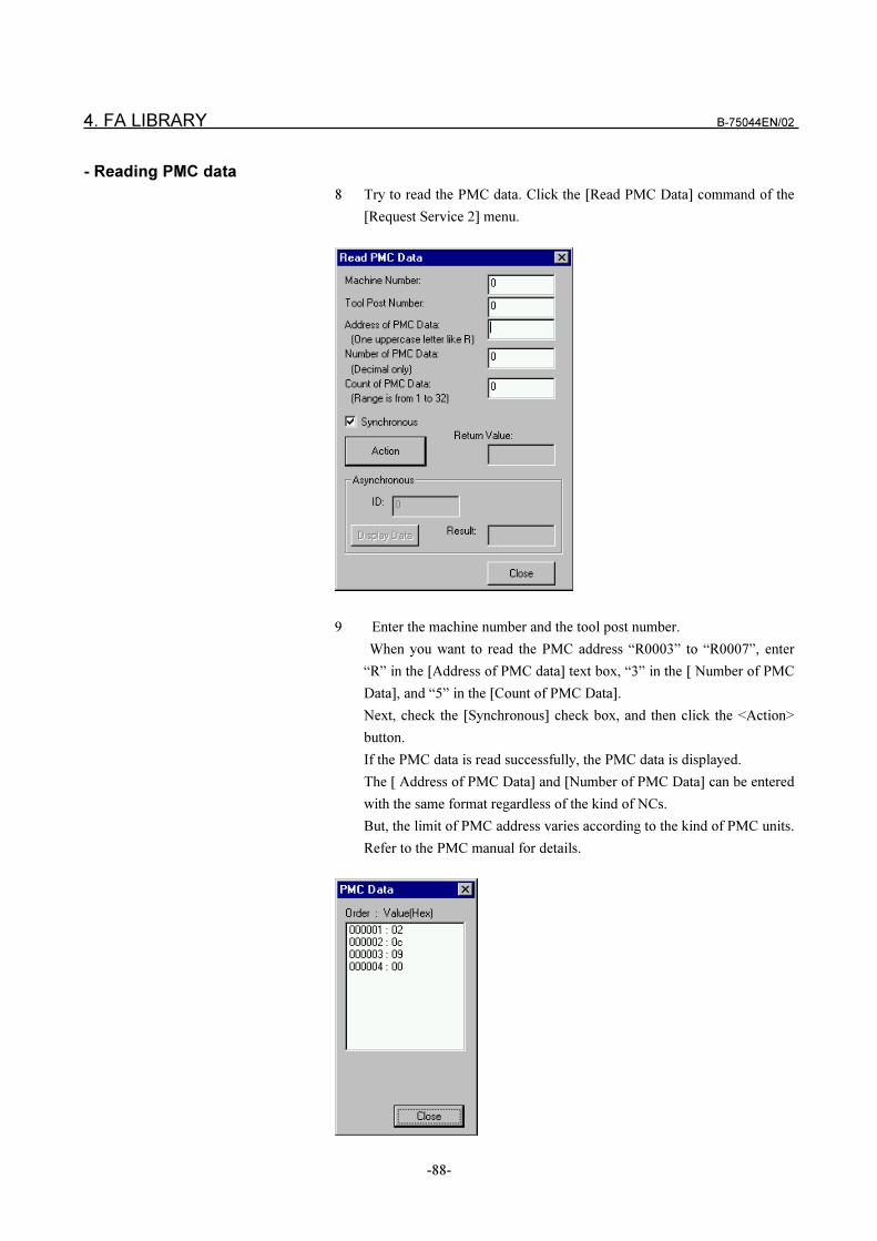
4. FA LIBRARY B-75044EN/02
-88-
- Reading PMC data
8 Try to read the PMC data. Click the [Read PMC Data] command of the
[Request Service 2] menu.
9 Enter the machine number and the tool post number.
When you want to read the PMC address “R0003” to “R0007”, enter
“R” in the [Address of PMC data] text box, “3” in the [ Number of PMC
Data], and “5” in the [Count of PMC Data].
Next, check the [Synchronous] check box, and then click the <Action>
button.
If the PMC data is read successfully, the PMC data is displayed.
The [ Address of PMC Data] and [Number of PMC Data] can be entered
with the same format regardless of the kind of NCs.
But, the limit of PMC address varies according to the kind of PMC units.
Refer to the PMC manual for details.
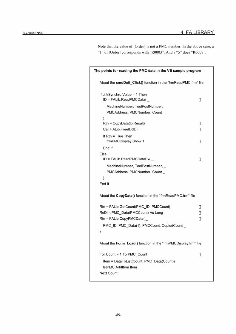
B-75044EN/02 4. FA LIBRARY
-89-
Note that the value of [Order] is not a PMC number. In the above case, a
“1” of [Order] corresponds with “R0003”. And a “5” does “R0007”.
The points for reading the PMC data in the VB sample program
About the cmdDoit_Click() function in the “frmReadPMC.frm” file
If chkSynchro.Value = 1 Then
ID = FALib.ReadPMCData( _ �
MachineNumber, ToolPostNumber, _
PMCAddress, PMCNumber, Count _
)
Rtn = CopyData(lblResult) �
Call FALib.FreeID(ID) �
If Rtn = True Then
frmPMCDisplay.Show 1 �
End If
Else
ID = FALib.ReadPMCDataEx( _ �
MachineNumber, ToolPostNumber, _
PMCAddress, PMCNumber, Count _
)
End If
About the CopyData() function in the “frmReadPMC.frm” file
Rtn = FALib.GetCount(PMC_ID, PMCCount) �
ReDim PMC_Data(PMCCount) As Long �
Rtn = FALib.CopyPMCData( _ �
PMC_ID, PMC_Data(1), PMCCount, CopiedCount _
)
About the Form_Load() function in the “frmPMCDisplay.frm” file
For Count = 1 To PMC_Count �
Item = DataToList(Count, PMC_Data(Count))
lstPMC.AddItem Item
Next Count
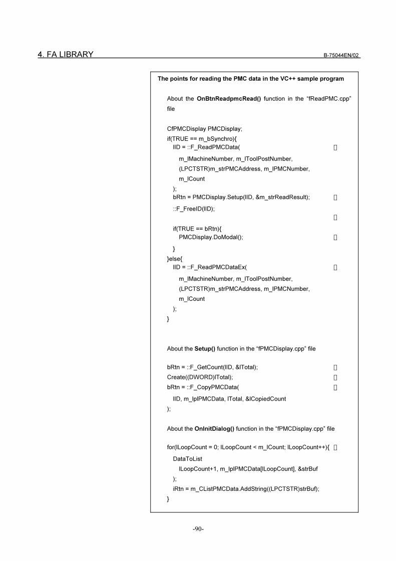
4. FA LIBRARY B-75044EN/02
-90-
The points for reading the PMC data in the VC++ sample program
About the OnBtnReadpmcRead() function in the “fReadPMC.cpp”
file
CfPMCDisplay PMCDisplay;
if(TRUE == m_bSynchro){
lID = ::F_ReadPMCData( �
m_lMachineNumber, m_lToolPostNumber,
(LPCTSTR)m_strPMCAddress, m_lPMCNumber,
m_lCount
);
bRtn = PMCDisplay.Setup(lID, &m_strReadResult); �
::F_FreeID(lID);
�
if(TRUE == bRtn){
PMCDisplay.DoModal(); �
}
}else{
lID = ::F_ReadPMCDataEx( �
m_lMachineNumber, m_lToolPostNumber,
(LPCTSTR)m_strPMCAddress, m_lPMCNumber,
m_lCount
);
}
About the Setup() function in the “fPMCDisplay.cpp” file
bRtn = ::F_GetCount(lID, &lTotal); �
Create((DWORD)lTotal); �
bRtn = ::F_CopyPMCData( �
lID, m_lplPMCData, lTotal, &lCopiedCount
);
About the OnInitDialog() function in the “fPMCDisplay.cpp” file
for(lLoopCount = 0; lLoopCount < m_lCount; lLoopCount++){ �
DataToList
lLoopCount+1, m_lplPMCData[lLoopCount], &strBuf
);
iRtn = m_CListPMCData.AddString((LPCTSTR)strBuf);
}
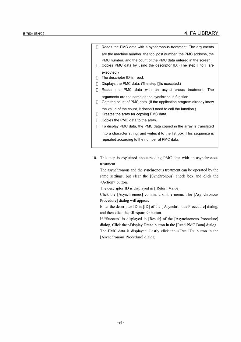
B-75044EN/02 4. FA LIBRARY
-91-
� Reads the PMC data with a synchronous treatment. The arguments
are the machine number, the tool post number, the PMC address, the
PMC number, and the count of the PMC data entered in the screen.
� Copies PMC data by using the descriptor ID. (The step � to � are
executed.)
� The descriptor ID is freed.
� Displays the PMC data. (The step � is executed.)
� Reads the PMC data with an asynchronous treatment. The
arguments are the same as the synchronous function.
� Gets the count of PMC data. (If the application program already knew
the value of the count, it doesn’t need to call the function.)
� Creates the array for copying PMC data.
� Copies the PMC data to the array.
� To display PMC data, the PMC data copied in the array is translated
into a character string, and writes it to the list box. This sequence is
repeated according to the number of PMC data.
10 This step is explained about reading PMC data with an asynchronous
treatment.
The asynchronous and the synchronous treatment can be operated by the
same settings, but clear the [Synchronous] check box and click the
<Action> button.
The descriptor ID is displayed in [ Return Value].
Click the [Asynchronous] command of the menu. The [Asynchronous
Procedure] dialog will appear.
Enter the descriptor ID in [ID] of the [ Asynchronous Procedure] dialog,
and then click the <Response> button.
If “Success” is displayed in [Result] of the [Asynchronous Procedure]
dialog, Click the <Display Data> button in the [Read PMC Data] dialog.
The PMC data is displayed. Lastly click the <Free ID> button in the
[Asynchronous Procedure] dialog.
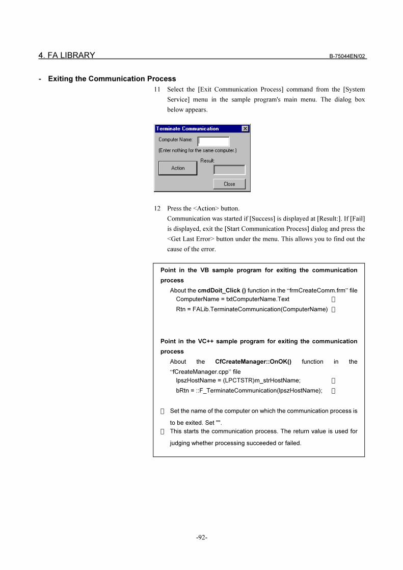
4. FA LIBRARY B-75044EN/02
-92-
- Exiting the Communication Process
11 Select the [Exit Communication Process] command from the [System
Service] menu in the sample program's main menu. The dialog box
below appears.
12 Press the <Action> button.
Communication was started if [Success] is displayed at [Result:]. If [Fail]
is displayed, exit the [Start Communication Process] dialog and press the
<Get Last Error> button under the menu. This allows you to find out the
cause of the error.
Point in the VB sample program for exiting the communication
process
About the cmdDoit_Click () function in the “frmCreateComm.frm” file
ComputerName = txtComputerName.Text �
Rtn = FALib.TerminateCommunication(ComputerName) �
Point in the VC++ sample program for exiting the communication
process
About the CfCreateManager::OnOK() function in the
“fCreateManager.cpp” file
lpszHostName = (LPCTSTR)m_strHostName; �
bRtn = ::F_TerminateCommunication(lpszHostName); �
� Set the name of the computer on which the communication process is
to be exited. Set "".
� This starts the communication process. The return value is used for
judging whether processing succeeded or failed.
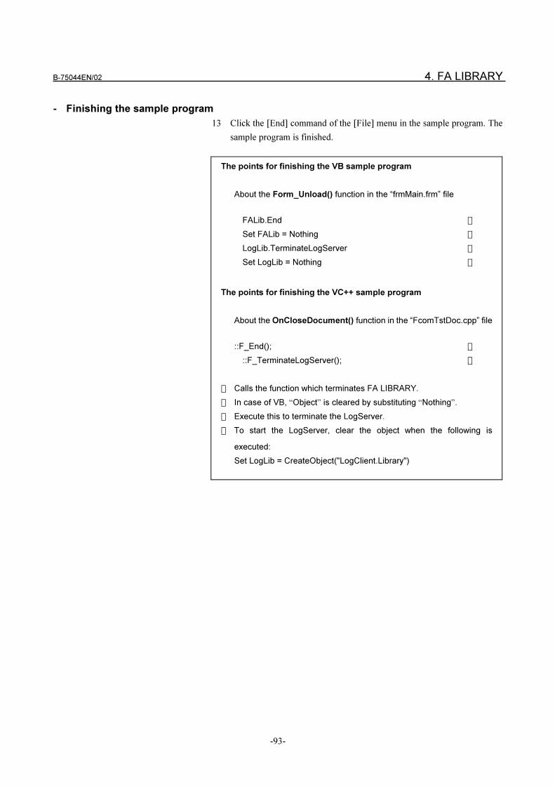
B-75044EN/02 4. FA LIBRARY
-93-
- Finishing the sample program
13 Click the [End] command of the [File] menu in the sample program. The
sample program is finished.
The points for finishing the VB sample program
About the Form_Unload() function in the “frmMain.frm” file
FALib.End �
Set FALib = Nothing �
LogLib.TerminateLogServer �
Set LogLib = Nothing �
The points for finishing the VC++ sample program
About the OnCloseDocument() function in the “FcomTstDoc.cpp” file
::F_End(); �
::F_TerminateLogServer(); �
� Calls the function which terminates FA LIBRARY.
� In case of VB, “Object” is cleared by substituting “Nothing”.
� Execute this to terminate the LogServer.
� To start the LogServer, clear the object when the following is
executed:
Set LogLib = CreateObject("LogClient.Library")
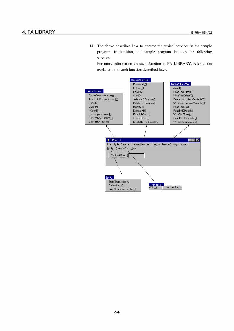
4. FA LIBRARY B-75044EN/02
-94-
14 The above describes how to operate the typical services in the sample
program. In addition, the sample program includes the following
services.
For more information on each function in FA LIBRARY, refer to the
explanation of each function described later.
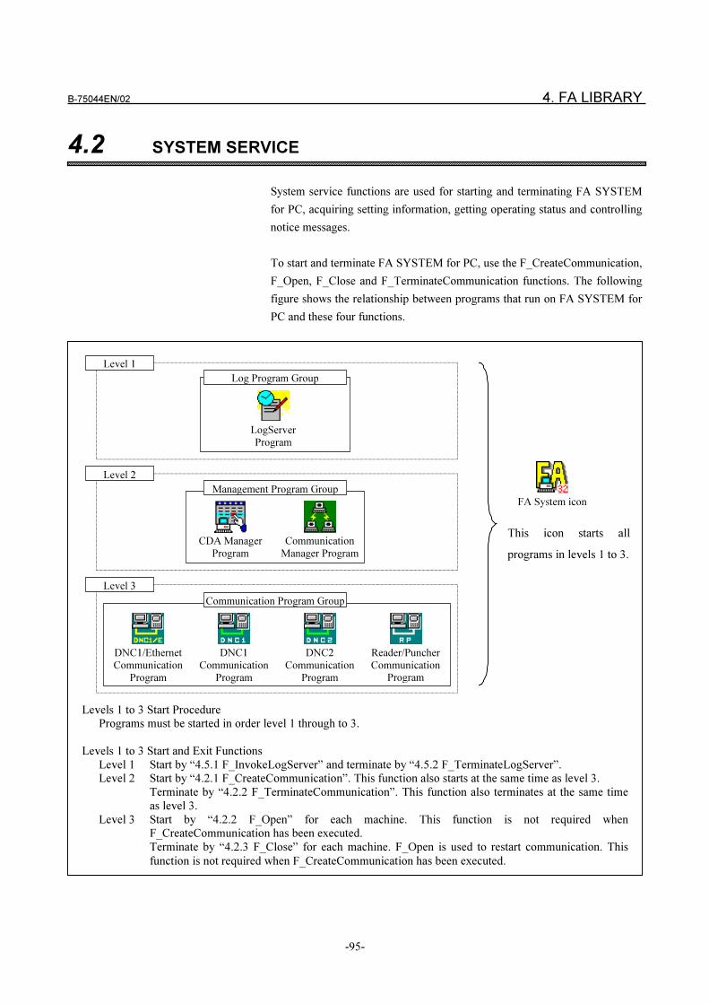
B-75044EN/02 4. FA LIBRARY
-95-
4.2 SYSTEM SERVICE
System service functions are used for starting and terminating FA SYSTEM
for PC, acquiring setting information, getting operating status and controlling
notice messages.
To start and terminate FA SYSTEM for PC, use the F_CreateCommunication,
F_Open, F_Close and F_TerminateCommunication functions. The following
figure shows the relationship between programs that run on FA SYSTEM for
PC and these four functions.
Levels 1 to 3 Start ProcedurePrograms must be started in order level 1 through to 3.
Levels 1 to 3 Start and Exit Functions
Level 1 Start by “4.5.1 F_InvokeLogServer” and terminate by “4.5.2 F_TerminateLogServer”.Level 2 Start by “4.2.1 F_CreateCommunication”. This function also starts at the same time as level 3.
Terminate by “4.2.2 F_TerminateCommunication”. This function also terminates at the same time
as level 3.
Level 3 Start by “4.2.2 F_Open” for each machine. This function is not required whenF_CreateCommunication has been executed.
Terminate by “4.2.3 F_Close” for each machine. F_Open is used to restart communication. This
function is not required when F_CreateCommunication has been executed.
LogServer
Program
Log Program Group
DNC1/Ethernet
Communication
Program
DNC1
Communication
Program
Reader/Puncher
Communication
Program
DNC2
Communication
Program
Communication Program Group
CDA Manager
Program
Communication
Manager Program
Management Program Group
Level 3
Level 2
Level 1
This icon starts all
programs in levels 1 to 3.
FA System icon
4. FA LIBRARY B-75044EN/02
-96-
To start FA SYSTEM for PC manually, click the [FA System] icon as
described in "2.5 Starting and Stopping FA SYSTEM for PC."
Follow the procedure below to communicate with an NC by FA SYSTEM for
PC.
First start a level 1 program. Start the LogServer by F_InvokeLogServer.
Next, start levels 2 and 3 simultaneously using F_CreateCommunication.
Communication with each machine cannot be initiated without starting
F_CreateCommunication. If a level 2 program has been started by
F_CreateCommunication, then you can terminate the communication program
for each machine by F_Close or start the communication program for each
machine by F_Open.
When level 1 to 3 programs are started, download, upload and read/write of
variables are possible using the functions described in "4.3 Request Service."
4.2.1 Start of Communication Process < F_CreateCommunication > *
SYNOPSIS
VB Function CreateCommunication() As Boolean
C++ BOOL F_CreateCommunication(void);
DESCRIPTION
F_CreateCommunication starts the communication process in the
computer where the application program is running.
It is necessary that the communication process and the calling application are
in the same directory.
When the communication process is already started according to “2.5 Starting
and Stopping the Communication Process”, it isn’t necessary to start it.
This function doesn’t have any effect if the communication process is already
started.
NOTE
1 To execute this function, a level 1 program must already be executed.
2 When this function is executed, the "4.2.3 Start of
Communication<F_Open>" function is automatically executed on all
machines set in the Machine Setup screen. So, the F_Open function
need not be executed for each machine.
If you execute the F_Open function after this function is executed, the
error "Communication is already started (error code: 0x00010001)"
occurs.
You may ignore this error.
B-75044EN/02 4. FA LIBRARY
-97-
RETURN VALUE
TRUE is returned if F_CreateCommunication succeeds, FALSE is
returned if it fails.
In failure, an error code can be acquired by calling F_GetLastError.
4.2.2 End of Communication Process
< F_TerminateCommunication > *
SYNOPSIS
VB Function TerminateCommunication
(ByVal ComputerName As String) As Boolean
C++ BOOL F_TerminateCommunication (LPCTSTR ComputerName);
DESCRIPTION
F_TerminateCommunication terminates the communication process
which is running in the computer specified by ComputerName. When the
value of ComputerName is NULL, or when the character length of
ComputerName is zero, F_TerminateCommunication can terminate
the communication process in the computer where the application program is
running .
RETURN VALUE
TRUE is returned if F_TerminateCommunication succeeds, FALSE is
returned if it fails.
In failure, an error code can be acquired by calling F_GetLastError.
NOTE
1 To exit FA SYSTEM for PC, be sure to execute this function to exit
level 2 programs. Level 2 programs are not exited even if you execute
F_Close for all machines.
2 When this function is executed, the "4.2.4 Stop of
Communication<F_Close>" function is automatically executed on all
machines set in the Machine Setup screen. So, the F_Close function
need not be executed for each machine.
If you execute the F_Close function after this function is executed, the
error "Communication Manager is not started (error code:
0x1004020f)" occurs.
You may ignore this error.
4. FA LIBRARY B-75044EN/02
-98-
4.2.3 Start of Communication < F_Open >
SYNOPSIS
VB Function Open(ByVal MachineNumber As Long) As Boolean
C++ BOOL F_Open(LONG MachineNumber);
DESCRIPTION
F_Open starts communicating with the NC of the machine number specified
by MachineNumber.
RETURN VALUE
TRUE is returned if F_Open succeeds, FALSE is returned if it fails.
In failure, an error code can be acquired by calling F_GetLastError.
NOTE
1 This function is used to start communication for each machine.
To use this function, you must execute F_InvokeLogServer and
F_CreateCommunication to start level 1 and level 2 programs.
If you execute this function when level 1 and level 2 functions are not
started, the error "Communication Manager is not started (error code:
0x1004020f)" occurs.
2 When you execute F_CreateCommunication, communication with all
registered machines is started.
B-75044EN/02 4. FA LIBRARY
-99-
4.2.4 Stop of Communication < F_Close >
SYNOPSIS
VB Function Close(ByVal MachineNumber As Long) As Boolean
C++ BOOL F_Close(LONG MachineNumber);
DESCRIPTION
F_Close stops communicating with the NC of the machine number specified
by MachineNumber. F_Close is applied to level 3 programs.
RETURN VALUE
TRUE is returned if F_Close succeeds, FALSE is returned if it fails.
In failure, an error code can be acquired by calling F_GetLastError.
4.2.5 Confirmation of Communication < F_IsOpen >
SYNOPSIS
VB Function IsOpen (ByVal MachineNumber As Long) As Boolean
C++ BOOL F_IsOpen(LONG MachineNumber);
DESCRIPTION
F_IsOpen checks whether the computer communicates with the NC of the
machine number specified by MachineNumber.
RETURN VALUE
F_IsOpen returns TRUE if the computer is communicating with the
specified machine. Otherwise, FALSE is returned.
NOTE
1 This function is used for terminating communication with each
machine.
Level 2 programs are not terminated even if you execute this function
on all machines. To exit FA SYSTEM for PC, be sure to execute
F_TerminateCommunication.
2 When you execute F_TerminateCommunication, communication with
all registered machines is terminated.
4. FA LIBRARY B-75044EN/02
-100-
4.2.6 Getting List of Registered Machine Numbers
<F_GetAllMachineNumber >
SYNOPSIS
VB Function GetAllMachineNumber
(ByVal ComputerName As String) As Long
C++ LONG F_GetAllMachineNumber (LPCTSTR ComputerName);
VB Function CopyMachineNumber
(ByVal ID As Long, MachineList As Long, ByVal Count As Long,
CopiedCount As Long) As Boolean
C++ BOOL F_CopyMachineNumber
(LONG ID, LONG* MachineList, LONG Count,
LONG* CopiedCount);
DESCRIPTION
The following describes the procedure for getting the list of the registered
machines which are defined in the Machine Configuration screen.
1 F_GetAllMachineNumber gets the list of the machines registered in
the computer specified by ComputerName.
When the function succeeds, the return value indicates the descriptor ID
for pointing the list of the registered machine numbers.
2 F_GetCount gets the number of the registered machines associated
with the descriptor ID.
ID specifies the descriptor ID returned by F_GetAllMachineNumber.
Refer to Clause 4.4.1 for details
3 F_CopyMachineNumber takes out the list of the registered machine
numbers.
ID specifies the descriptor ID returned by F_GetAll MachineNumber.
Count specifies the number of the registered machines you want to read
at a time.
MachineList points to the array for placing machine numbers. The
array must be composed of the four-byte integral elements of the same
number as Count specifies.
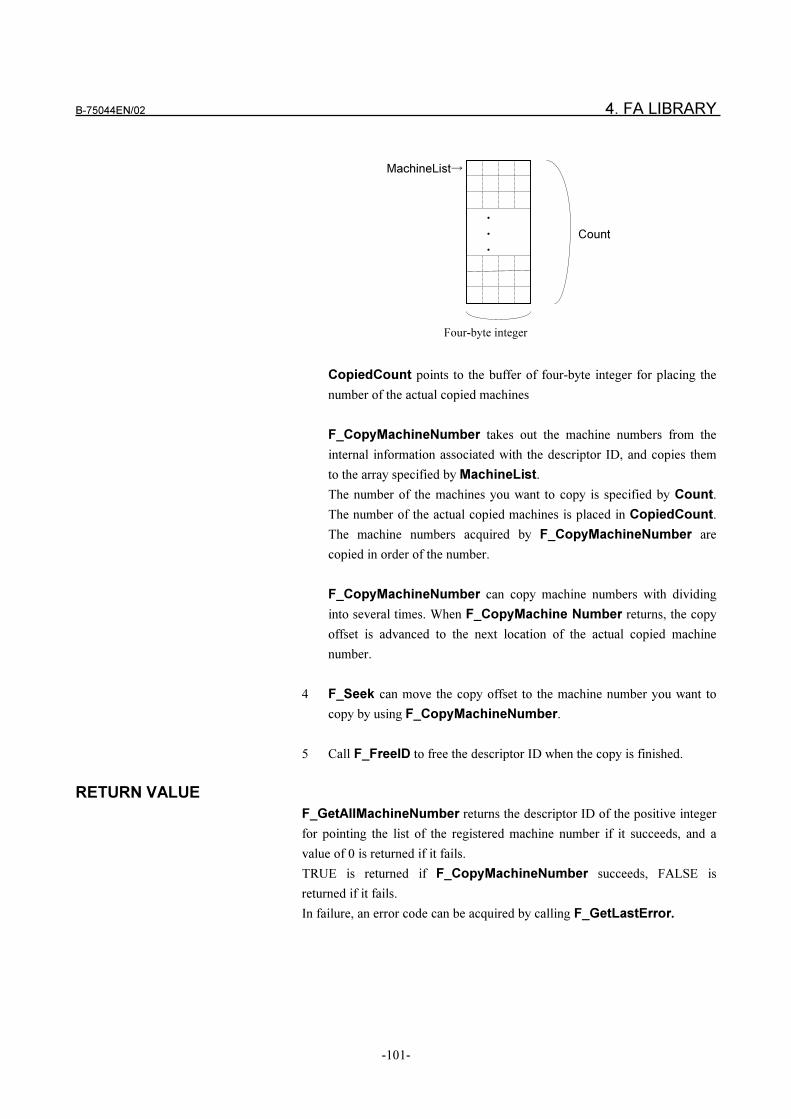
B-75044EN/02 4. FA LIBRARY
-101-
CopiedCount points to the buffer of four-byte integer for placing the
number of the actual copied machines
F_CopyMachineNumber takes out the machine numbers from the
internal information associated with the descriptor ID, and copies them
to the array specified by MachineList.
The number of the machines you want to copy is specified by Count.
The number of the actual copied machines is placed in CopiedCount.
The machine numbers acquired by F_CopyMachineNumber are
copied in order of the number.
F_CopyMachineNumber can copy machine numbers with dividing
into several times. When F_CopyMachine Number returns, the copy
offset is advanced to the next location of the actual copied machine
number.
4 F_Seek can move the copy offset to the machine number you want to
copy by using F_CopyMachineNumber.
5 Call F_FreeID to free the descriptor ID when the copy is finished.
RETURN VALUE
F_GetAllMachineNumber returns the descriptor ID of the positive integer
for pointing the list of the registered machine number if it succeeds, and a
value of 0 is returned if it fails.
TRUE is returned if F_CopyMachineNumber succeeds, FALSE is
returned if it fails.
In failure, an error code can be acquired by calling F_GetLastError.
�
�
�
MachineList�
Count
Four-byte integer
4. FA LIBRARY B-75044EN/02
-102-
4.2.7 Getting List of Communicating Machines
< F_GetOpenMachineNumber >
SYNOPSIS
VB Function GetOpenMachineNumber(ByVal ComputerName As String) As Long
C++ LONG F_GetOpenMachineNumber(LPCTSTR ComputerName);
DESCRIPTION
The following describes the procedure for getting the list of the
communicating machine numbers.
1 F_GetOpenMachineNumber can get the list of the machines which
are communicating with the computer specified by ComputerName.
When the function succeeds, the return value indicates the descriptor ID
for pointing the list of the communicating machines.
2 F_CopyMachineNumber takes out the machines associated with the
descriptor ID. Refer to Clause 4.2.6 “Getting List of Registered Machine
Numbers” for the details
RETURN VALUE
F_GetOpenMachineNumber returns the descriptor ID of a positive
integer for placing the list of the communicating machines if it succeeds, and a
value of 0 is returned if it fails.
In failure, an error code can be acquired by calling F_GetLastError.
B-75044EN/02 4. FA LIBRARY
-103-
4.2.8 Start of Receiving Notice Message < F_StartNotice >
SYNOPSIS
VB Function StartNotice (ByVal ComputerName As String) As Boolean
C++ BOOL F_StartNotice(LPCTSTR ComputerName);
DESCRIPTION
When an application program calls F_StartNotice, the communication
process starts sending notice messages to it.
A notice message is the information for notifying an application program of
the status of the communication process.
The communication process reports the start and end of
downloading/uploading by operating NC side to an application program.
The communication process is running in the computer specified by
ComputerName. When the value of ComputerName is NULL, a notice
message will be sent from the communication process in the computer where
the calling application program is running.
Only one application can receive notice messages from the communication
process.
When one application has already called the function and has been receiving a
notice message from the computer specified by ComputerName, other
applications fail in the call of this function.
RETURN VALUE
TRUE is returned if F_StartNotice succeeds, FALSE is returned if it fails.
In failure, an error code can be acquired by calling F_GetLastError.
4. FA LIBRARY B-75044EN/02
-104-
4.2.9 End of Receiving Notice Message < F_StopNotice >
SYNOPSIS
VB Function StopNotice(ByVal ComputerName As String) As Boolean
C++ BOOL F_StopNotice(LPCTSTR ComputerName);
DESCRIPTION
When an application program calls F_StopNotice, the communication
process stops sending the notice messages. The communication process is
running in the computer specified by ComputerName. When the value of
ComputerName is NULL, the function selects the communication process
in the computer where the application program is running.
F_StopNotice can be called by the application program that called
F_StartNotice before.
RETURN VALUE
TRUE is returned if F_StopNotice succeeds, FALSE is returned if it fails.
In failure, an error code can be acquired by calling F_GetLastError.
4.2.10 Getting Descriptor ID of Notice Message < F_GetNoticeID >
SYNOPSIS
VB Function GetNoticeID
(ID As Long, RequestCode As Long,
MachineNumber As Long) As Boolean
C++ BOOL F_GetNoticeID
(LONG* ID, LONG* RequestCode, LONG* MachineNumber);
DESCRIPTION
F_GetNoticeID reads the notice message sent by the communication process.
When a message is sent, the descriptor ID of the positive integer is placed in
ID, the request code is placed in RequestCode, and the machine number is
placed in MachineNumber.
When there is no message, the value of 0 is set to ID. And no value is set to
RequestCode and MachineNumber.
RETURN VALUE
TRUE is returned if F_GetNoticeID succeeds, FALSE is returned if it fails.
In failure, an error code can be acquired by calling F_GetLastError.
B-75044EN/02 4. FA LIBRARY
-105-
4.2.11 Getting the Notice Message of the File Transfer
< F_CopyNoticeFileTransfer >
SYNOPSIS
VB Function CopyNoticeFileTransfer
(ByVal ID As Long, Type As Long, ToolPostNumber As Long,
Key As String) As Boolean
C++ BOOL F_CopyNoticeFileTransfer
(LONG ID, LONG* Type, LONG* ToolPostNumber, LPCTSTR Key);
DESCRIPTION
When F_GetNoticeID returns the following request code,
F_CopyNoticeFileTransfer can take out the notice message.
Request Code Explanation
0x00100001 The Start and End of Downloading NC Program
Requested by NC
0x00100002 The Start and End of Uploading NC Program
Requested by NC
ID specifies descriptor ID returned by F_GetNoticeID.
The notice message is placed in the following arguments.
Type points to the four-byte integral flag for placing either of the start or
end flag. The value of “0x0” is the start flag, and “0xFFFFFFFF” is the end
flag.
ToolPostNumber points to the four-byte integral value for placing the tool
post number.
Key points to the four-byte integral value for placing the key used to transfer.
Call F_FreeID to free the descriptor ID when F_CopyNotice
FileTransfer is finished.
RETURN VALUE
TRUE is returned if F_CopyNoticeFileTransfer succeeds, FALSE is
returned if it fails.
In failure, an error code can be acquired by calling F_GetLastError.
4. FA LIBRARY B-75044EN/02
-106-
4.2.12 Getting Information about Machine < F_GetMachineInfo >
SYNOPSIS
VB Function GetMachineInfo
(ByVal MachineNumber As Long, ByVal Name As String,
ByVal Protocol As String) As Boolean
C++ BOOL F_GetMachineInfo
(LONG MachineNumber, LPCTSTR Name, LPCTSTR Protocol);
DESCRIPTION
F_GetMachineInfo reads the information of the machine specified by
MachineNumber
The machine information is placed in the following arguments.
Name points to the buffer for placing the machine name.
Protocol points to the buffer for placing the protocol type.
Each buffer must be a sequence of 33 characters or more length and each
character string is terminated by a NULL character.
The following is the character string written in Protocol .
The String of Protocol Explanation
“DNC1” DNC1
“DNC2” DNC2
“RP” Reader/Puncher
“DNC1ETHER” DNC1/Ethernet
RETURN VALUE
TRUE is returned if F_GetMachineInfo succeeds, FALSE is returned if it
fails.
F_GetMachineInfo fails if the protocol type of a machine is registered with
“NONE” in the Machine Configuration Screen.
In failure, an error code can be acquired by calling F_GetLastError.
B-75044EN/02 4. FA LIBRARY
-107-
4.3 REQUEST SERVICE
4.3.1 Downloading NC Program requested by Computer
< F_Download... >
FA LIBRARY provides the four functions which can download an NC
program by using one of “file number”, “NC program number”, “file name”,
and “full path”, explained in Section 1.3. The four functions can be called
with a synchronous and an asynchronous treatment.
SYNOPSIS
<The file to be downloaded is specified by “ file number”>
In case of the synchronous treatment
VB Function DownloadFileNumber
(ByVal MachineNumber As Long, ByVal ToolPostNumber As Long,
ByVal FileNumber As Long) As Boolean
C++ BOOL F_DownloadFileNumber
(LONG MachineNumber, LONG ToolPostNumber,
LONG FileNumber);
In case of the asynchronous treatment
VB Function DownloadFileNumberEx
(ByVal MachineNumber As Long, ByVal ToolPostNumber As Long,
ByVal FileNumber As Long) As Long
NOTE
When DNC1/Ethernet is used for communicating with an NC, the
download is not reset even if you press the RESET key on the NC
during a download of the NC program requested by the computer.
(Until either the download ends successfully, or the download does not
end until an NC memory overflow or other error causes an NC alarm.)
To cancel the download of the NC program requested by the
computer, use the "cancel download of the NC program requested by
the computer " function described later.
To use this function, you must execute the download of the NC
program requested by the computer asynchronously. If the download
is executed synchronously, the application will not be returned to until
the download function ends. For this reason, the cancel function
cannot be used.
4. FA LIBRARY B-75044EN/02
-108-
C++ LONG F_DownloadFileNumberEx
(LONG MachineNumber, LONG ToolPostNumber,
LONG FileNumber);
<The file to be downloaded is specified by “file name”>
In case of the synchronous treatment
VB Function DownloadFileName
(ByVal MachineNumber As Long, ByVal ToolPostNumber As Long,
ByVal FileName As String) As Boolean
C++ BOOL F_DownloadFileName
(LONG MachineNumber, LONG ToolPostNumber,
LPCTSTR FileName);
In case of the asynchronous treatment
VB Function DownloadFileNameEx
(ByVal MachineNumber As Long, ByVal ToolPostNumber As Long,
ByVal FileName As String) As Long
C++ LONG F_DownloadFileNameEx
(LONG MachineNumber, LONG ToolPostNumber,
LPCTSTR FileName);
<The file to be downloaded is specified by “NC program number” >
In case of the synchronous treatment
VB Function DownloadONumber
(ByVal MachineNumber As Long, ByVal ToolPostNumber As Long,
ByVal ONumber As Long) As Boolean
C++ BOOL F_DownloadONumber
(LONG MachineNumber, LONG ToolPostNumber,
LONG ONumber);
In case of the asynchronous treatment
VB Function DownloadONumberEx
(ByVal MachineNumber As Long, ByVal ToolPostNumber As Long,
ByVal ONumber As Long) As Long
C++ LONG F_DownloadONumberEx
(LONG MachineNumber, LONG ToolPostNumber,
LONG ONumber);
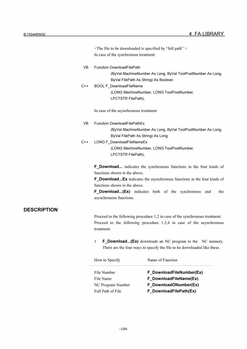
B-75044EN/02 4. FA LIBRARY
-109-
<The file to be downloaded is specified by “full path” >
In case of the synchronous treatment
VB Function DownloadFilePath
(ByVal MachineNumber As Long, ByVal ToolPostNumber As Long,
ByVal FilePath As String) As Boolean
C++ BOOL F_DownloadFileName
(LONG MachineNumber, LONG ToolPostNumber,
LPCTSTR FilePath);
In case of the asynchronous treatment
VB Function DownloadFilePathEx
(ByVal MachineNumber As Long, ByVal ToolPostNumber As Long,
ByVal FilePath As String) As Long
C++ LONG F_DownloadFileNameEx
(LONG MachineNumber, LONG ToolPostNumber,
LPCTSTR FilePath);
F_Download... indicates the synchronous functions in the four kinds of
functions shown in the above.
F_Download...Ex indicates the asynchronous functions in the four kinds of
functions shown in the above.
F_Download...(Ex) indicates both of the synchronous and the
asynchronous functions.
DESCRIPTION
Proceed to the following procedure 1,2 in case of the synchronous treatment.
Proceed to the following procedure 1,3,4 in case of the asynchronous
treatment.
1 F_Download...(Ex) downloads an NC program to the NC memory.
There are the four ways to specify the file to be downloaded like these.
How to Specify Name of Function
File Number F_DownloadFileNumber(Ex)
File Name F_DownloadFileName(Ex)
NC Program Number F_DownloadONumber(Ex)
Full Path of File F_DownloadFilePath(Ex)
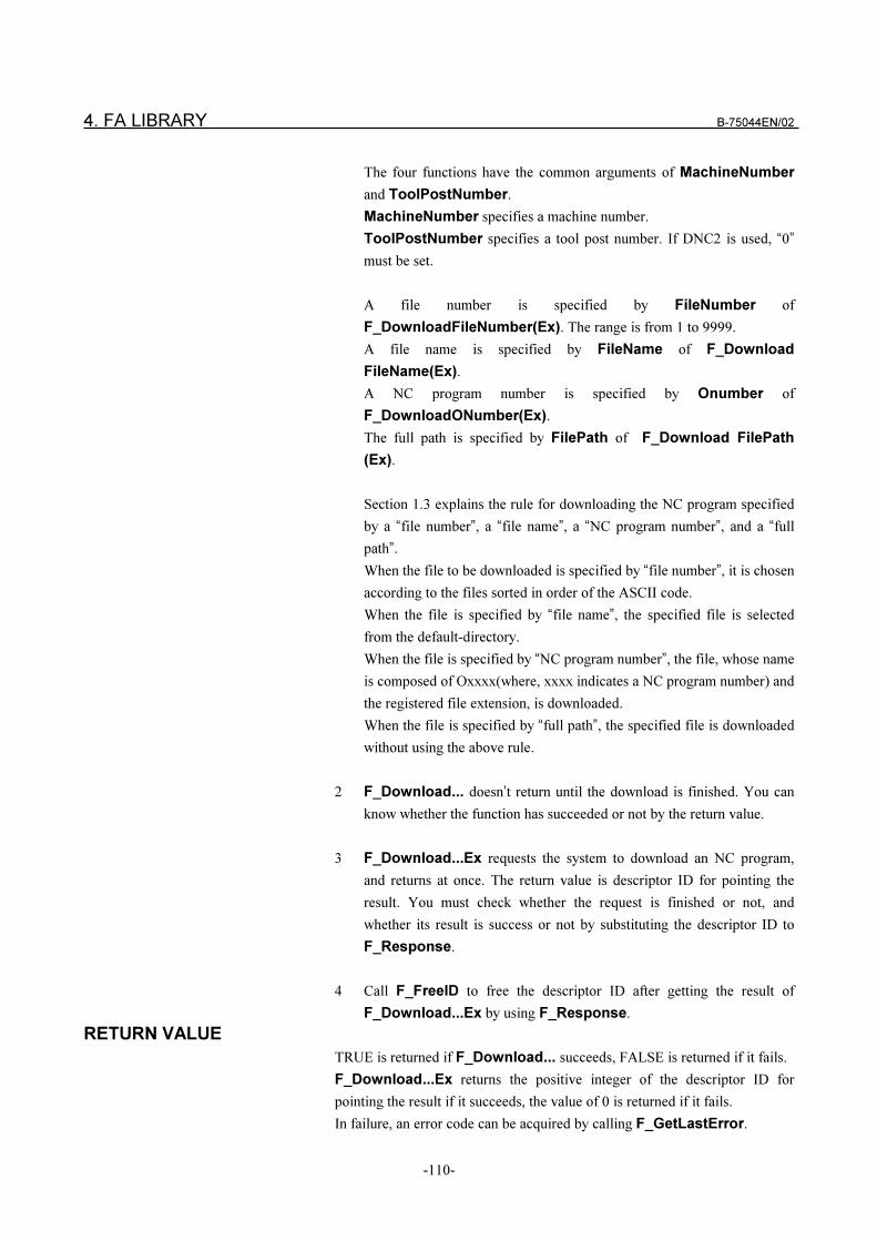
4. FA LIBRARY B-75044EN/02
-110-
The four functions have the common arguments of MachineNumber
and ToolPostNumber.
MachineNumber specifies a machine number.
ToolPostNumber specifies a tool post number. If DNC2 is used, “0”
must be set.
A file number is specified by FileNumber of
F_DownloadFileNumber(Ex). The range is from 1 to 9999.
A file name is specified by FileName of F_Download
FileName(Ex).
A NC program number is specified by Onumber of
F_DownloadONumber(Ex).
The full path is specified by FilePath of F_Download FilePath
(Ex).
Section 1.3 explains the rule for downloading the NC program specified
by a “file number”, a “file name”, a “NC program number”, and a “full
path”.
When the file to be downloaded is specified by “file number”, it is chosen
according to the files sorted in order of the ASCII code.
When the file is specified by “file name”, the specified file is selected
from the default-directory.
When the file is specified by “NC program number”, the file, whose name
is composed of Oxxxx(where, xxxx indicates a NC program number) and
the registered file extension, is downloaded.
When the file is specified by “full path”, the specified file is downloaded
without using the above rule.
2 F_Download... doesn’t return until the download is finished. You can
know whether the function has succeeded or not by the return value.
3 F_Download...Ex requests the system to download an NC program,
and returns at once. The return value is descriptor ID for pointing the
result. You must check whether the request is finished or not, and
whether its result is success or not by substituting the descriptor ID to
F_Response.
4 Call F_FreeID to free the descriptor ID after getting the result of
F_Download...Ex by using F_Response.
RETURN VALUE
TRUE is returned if F_Download... succeeds, FALSE is returned if it fails.
F_Download...Ex returns the positive integer of the descriptor ID for
pointing the result if it succeeds, the value of 0 is returned if it fails.
In failure, an error code can be acquired by calling F_GetLastError.
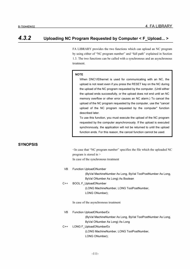
B-75044EN/02 4. FA LIBRARY
-111-
4.3.2 Uploading NC Program Requested by Computer < F_Upload... >
FA LIBRARY provides the two functions which can upload an NC program
by using either of “NC program number” and “full path” explained in Section
1.3. The two functions can be called with a synchronous and an asynchronous
treatment.
SYNOPSIS
<In case that “NC program number” specifies the file which the uploaded NC
program is stored in >
In case of the synchronous treatment
VB Function UploadONumber
(ByVal MachineNumber As Long, ByVal ToolPostNumber As Long,
ByVal ONumber As Long) As Boolean
C++ BOOL F_UploadONumber
(LONG MachineNumber, LONG ToolPostNumber,
LONG ONumber);
In case of the asynchronous treatment
VB Function UploadONumberEx
(ByVal MachineNumber As Long, ByVal ToolPostNumber As Long,
ByVal ONumber As Long) As Long
C++ LONG F_UploadONumberEx
(LONG MachineNumber, LONG ToolPostNumber,
LONG ONumber);
NOTE
When DNC1/Ethernet is used for communicating with an NC, the
upload is not reset even if you press the RESET key on the NC during
the upload of the NC program requested by the computer. (Until either
the upload ends successfully, or the upload does not end until an NC
memory overflow or other error causes an NC alarm.) To cancel the
upload of the NC program requested by the computer, use the "cancel
upload of the NC program requested by the computer" function
described later.
To use this function, you must execute the upload of the NC program
requested by the computer asynchronously. If the upload is executed
synchronously, the application will not be returned to until the upload
function ends. For this reason, the cancel function cannot be used.
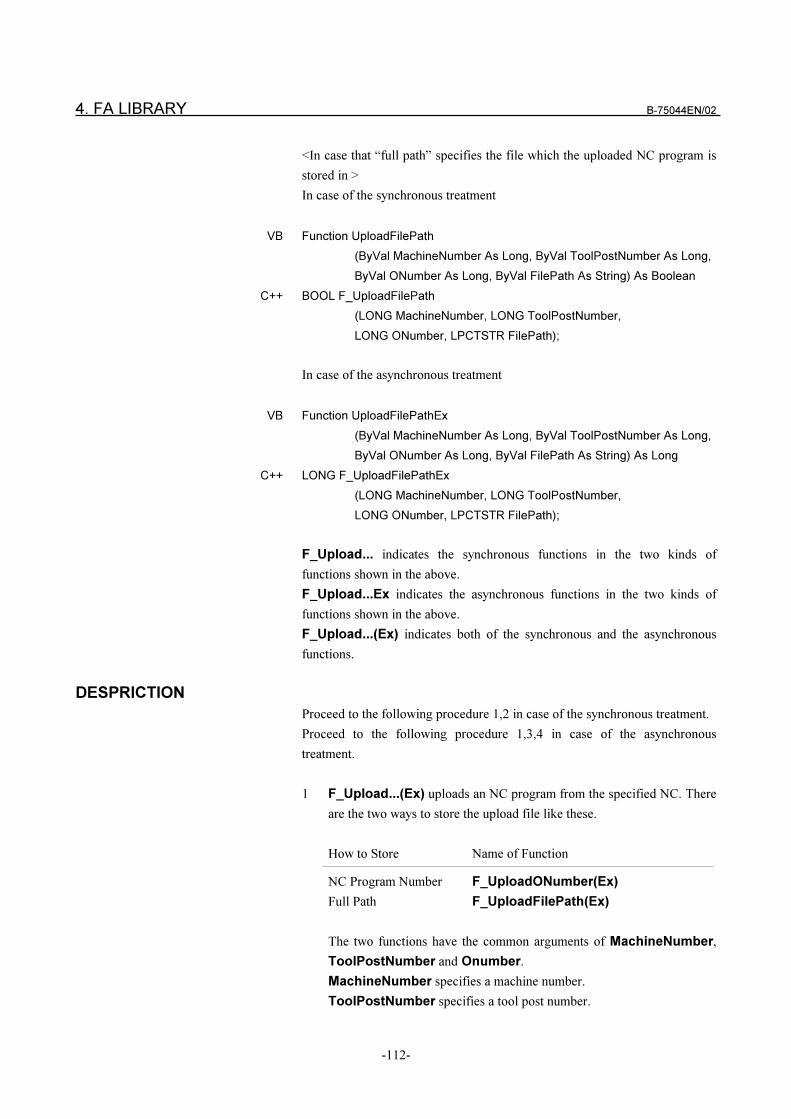
4. FA LIBRARY B-75044EN/02
-112-
<In case that “full path” specifies the file which the uploaded NC program is
stored in >
In case of the synchronous treatment
VB Function UploadFilePath
(ByVal MachineNumber As Long, ByVal ToolPostNumber As Long,
ByVal ONumber As Long, ByVal FilePath As String) As Boolean
C++ BOOL F_UploadFilePath
(LONG MachineNumber, LONG ToolPostNumber,
LONG ONumber, LPCTSTR FilePath);
In case of the asynchronous treatment
VB Function UploadFilePathEx
(ByVal MachineNumber As Long, ByVal ToolPostNumber As Long,
ByVal ONumber As Long, ByVal FilePath As String) As Long
C++ LONG F_UploadFilePathEx
(LONG MachineNumber, LONG ToolPostNumber,
LONG ONumber, LPCTSTR FilePath);
F_Upload... indicates the synchronous functions in the two kinds of
functions shown in the above.
F_Upload...Ex indicates the asynchronous functions in the two kinds of
functions shown in the above.
F_Upload...(Ex) indicates both of the synchronous and the asynchronous
functions.
DESPRICTION
Proceed to the following procedure 1,2 in case of the synchronous treatment.
Proceed to the following procedure 1,3,4 in case of the asynchronous
treatment.
1 F_Upload...(Ex) uploads an NC program from the specified NC. There
are the two ways to store the upload file like these.
How to Store Name of Function
NC Program Number F_UploadONumber(Ex)
Full Path F_UploadFilePath(Ex)
The two functions have the common arguments of MachineNumber,
ToolPostNumber and Onumber.
MachineNumber specifies a machine number.
ToolPostNumber specifies a tool post number.
B-75044EN/02 4. FA LIBRARY
-113-
ONumber specifies NC program number you want to upload from the
NC.
F_UploadONumber(Ex) uploads the NC program specified by
ONumber , and stores it in the file specified by the same ONumber
argument.
Section 1.3 explains the way to store the file created from “NC program
number”.
The uploaded NC program is stored in the file whose name is composed
of Oxxxx(where, xxxx is the NC program number) and the registered file
extension.
The file is stored in the directory registered for each machine.
F_UploadFilePath(Ex) uploads the NC program specified by
ONumber, and stores it in the file specified by FilePath.
2 F_Upload... doesn’t return until the request is finished. You can know
whether the function has succeeded or not by the return value.
3 F_Upload...Ex requests the system to upload an NC program, and
returns at once. The return value is the descriptor ID for pointing the
result. You must check whether request is finished or not, and whether its
result is success or not by calling F_Response.
4 Call F_FreeID to free the descriptor ID after getting the result of
F_Upload...Ex from F_Response.
RETURN VALUE
TRUE is returned if F_Upload... succeeds, FALSE is returned if it fails.
F_Upload...Ex returns the positive integer of the descriptor ID for pointing
the result if it succeeds, the value of 0 is returned if it fails.
In failure, an error code can be acquired by calling F_GetLastError.
4. FA LIBRARY B-75044EN/02
-114-
4.3.3 External Reset < F_Reset >
SYNOPSIS
In case of the synchronous treatment
VB Function Reset
(ByVal MachineNumber As Long,
ByVal ToolPostNumber As Long) As Boolean
C++ BOOL F_Reset (LONG MachineNumber, LONG ToolPostNumber);
In case of the asynchronous treatment
VB Function ResetEx
(ByVal MachineNumber As Long,
ByVal ToolPostNumber As Long) As Long
C++ LONG F_ResetEx (LONG MachineNumber, LONG ToolPostNumber);
F_Reset(Ex) indicates both of the synchronous and the asynchronous
treatment.
DESCRIPTION
Proceed to the following procedure 1,2 in case of the synchronous treatment.
Proceed to the following procedure 1,3,4 in case of the asynchronous
treatment.
1 F_Reset(Ex) resets the NC specified by Machine Number and
ToolPostNumber.
2 F_Reset doesn’t return until the treatment is finished. You can know
whether the function has succeeded or not by the return value.
3 F_ResetEx requests the system to reset the NC, and returns at once.
The return value is the descriptor ID for pointing the result. You must
check whether the request is finished or not, and whether its result is
success or not by calling F_Response.
4 Call F_FreeID to free the descriptor ID after getting the result of
F_ResetEx by calling F_Response.
RETURN VALUE
TRUE is returned if F_Reset succeeds, FALSE is returned if it fails.
F_ResetEx returns the positive integer of the descriptor ID for pointing the
result if it succeeds, the value of 0 is returned if it fails.
In failure, an error code can be acquired by using F_GetLastError.
B-75044EN/02 4. FA LIBRARY
-115-
4.3.4 Cycle Start < F_Start >
SYNOPSIS
In case of the synchronous treatment
VB Function Start
(ByVal MachineNumber As Long,
ByVal ToolPostNumber As Long) As Boolean
C++ BOOL F_Start (LONG MachineNumber, LONG ToolPostNumber);
In case of the asynchronous treatment
VB Function StartEx
(ByVal MachineNumber As Long,
ByVal ToolPostNumber As Long) As Long
C++ LONG F_StartEx (LONG MachineNumber, LONG ToolPostNumber);
F_Start(Ex) indicates both of the synchronous and the asynchronous
treatment.
DESCRIPTION
Proceed to the following procedure 1,2 in case of the synchronous treatment.
Proceed to the following procedure 1,3,4 in case of the asynchronous
treatment.
1 F_Start(Ex) starts the NC specified by MachineNumber and
ToolPostNumber.
2 F_Start doesn’t return until the treatment is finished. You can know
whether the function has succeeded or not by the return value.
3 F_StartEx requests the system to start the NC, and returns at once. The
return value is the descriptor ID for pointing the result. You must check
whether the request is finished or not, and whether its result is success or
not by calling F_Response.
4 Call F_FreeID to free the descriptor ID after getting the result of
F_StartEx by calling F_Response.
NOTE
This function cannot be used on DNC1/Ethernet. (It is scheduled to be
supported in the future.) Use the PMC data write function to execute a
reset via the ladder program.
4. FA LIBRARY B-75044EN/02
-116-
RETURN VALUE
TRUE is returned if F_Start succeeds, FALSE is returned if it fails.
F_StartEx returns the positive integer of the descriptor ID for pointing the
result, if it succeeds. The value of 0 is returned if it fails.
In failure, an error code can be acquired by using F_GetLastError.
4.3.5 Selecting NC Program in NC < F_Select >
SYNOPSIS
In case of the synchronous treatment
VB Function Select
(ByVal MachineNumber As Long, ByVal ToolPostNumber As Long,
ByVal ONumber As Long) As Boolean
C++ BOOL F_Select
(LONG MachineNumber, LONG ToolPostNumber, LONG
Onumber);
In case of the asynchronous treatment
VB Function SelectEx
(ByVal MachineNumber As Long, ByVal ToolPostNumber As Long,
ByVal ONumber As Long) As Long
C++ LONG F_SelectEx
(LONG MachineNumber, LONG ToolPostNumber,
LONG ONumber);
F_Select(Ex) indicates both of the synchronous and the asynchronous
functions.
NOTE
This function cannot be used on DNC1/Ethernet. (It is scheduled to be
supported in the future.) Use the PMC data write function to execute a
cycle start via the ladder program.
B-75044EN/02 4. FA LIBRARY
-117-
DESCRIPTION
Proceed to the following procedure 1,2 in case of the synchronous treatment.
Proceed to the following procedure 1,3,4 in case of the asynchronous
treatment.
1 F_Select(Ex) selects the NC program in the NC specified by
MachineNumber and ToolPostNumber.
ONumber specifies the NC program number you want to select. The
range is from 1 to 9999.
2 F_Select doesn’t return until the treatment is finished. You can know
whether the function has succeeded or not by the return value.
3 F_SelectEx requests the system to select the NC program in the NC
memory, and returns at once. The return value is the descriptor ID for
pointing the result. You must check whether the request is finished or not,
and whether its result is success or not by calling F_Response.
4 Call F_FreeID to free the descriptor ID after getting the result of
F_SelectEx by calling F_Response.
RETURN VALUE
TRUE is returned if F_Select succeeds, FALSE is returned if it fails.
F_SelectEx returns the positive integer of the descriptor ID for pointing the
result if it succeeds. The value of 0 is returned if it fails.
In failure, an error code can be acquired by using F_GetLastError.
4.3.6 Deleting NC Program in NC < F_Delete >
SYNOPSIS
In case of the synchronous treatment
VB Function Delete
(ByVal MachineNumber As Long, ByVal ToolPostNumber As Long,
ByVal ONumber As Long) As Boolean
C++ BOOL F_Delete
(LONG MachineNumber, LONG ToolPostNumber,
LONG Onumber);
4. FA LIBRARY B-75044EN/02
-118-
In case of the asynchronous treatment
VB Function DeleteEx
(ByVal MachineNumber As Long, ByVal ToolPostNumber As Long,
ByVal ONumber As Long) As Long
C++ LONG F_DeleteEx
(LONG MachineNumber, LONG ToolPostNumber,
LONG ONumber);
F_Delete(Ex) indicates both of the synchronous and the asynchronous
functions.
DESCRIPTION
Proceed to the following procedure 1,2 in case of the synchronous treatment.
Proceed to the following procedure 1,3,4 in case of the asynchronous
treatment.
1 F_Delete(Ex) deletes the NC program in the NC specified by
MachineNumber and ToolPostNumber.
ONumber specifies the NC program number you want to delete. The
range is from 1 to 9999.
2 F_Delete doesn’t return until the treatment is finished. You can know
whether the function has succeeded or not by the return value.
3 F_DeleteEx requests the system to delete the NC program, and returns
at once. The return value is the descriptor ID for pointing the result. You
must check whether the request is finished or not, and whether its result
is success or not by calling F_Response.
4 Call F_FreeID to free the descriptor ID after getting the result of
F_DeleteEx by calling F_Response.
RETURN VALUE
TRUE is returned if F_Delete succeeds, FALSE is returned if it fails.
F_DeleteEx returns the positive integer of the descriptor ID for pointing the
result if it succeeds. The value of 0 is returned if it fails.
In failure, an error code can be acquired by calling F_GetLastError.
B-75044EN/02 4. FA LIBRARY
-119-
4.3.7 Reading NC Identification < F_Identify >
SYNOPSIS
In case of the synchronous treatment
VB Function Identify
(ByVal MachineNumber As Long,
ByVal Identify As String) As Boolean
C++ BOOL F_Identify
(LONG MachineNumber, LPCTSTR Identify);
In case of the asynchronous treatment
VB Function IdentifyEx (ByVal MachineNumber As Long) As Long
C++ LONG F_IdentifyEx(LONG MachineNumber);
F_Identify(Ex) indicates both of the synchronous and the asynchronous
functions.
VB Function F_CopyIdentify
(ByVal ID As Long, ByVal Identify As String) As Boolean
C++ BOOL F_CopyIdentify(LONG ID, LPCTSTR Identify);
DESCRIPTION
Proceed to the following procedure 1,2 in case of the synchronous treatment.
Proceed to the following procedure 1,3,4 in case of the asynchronous
treatment.
1 F_Identify(Ex) gets the identification of the NC specified by
MachineNumber.
In case of DNC1, the information is the sequence of the character string
in order of “model name”, “version”, and “vender name”. Each data is
separated by a comma “,” and the information is terminated by a NULL
character.
In case of DNC2, the information is the sequence of the character string
in order of “model name” and “version”.
Each data is separated by a comma “,” and the information is terminated
by a NULL character.
2 F_Identify reads the identification and takes out it.
Identify points to the buffer for placing the NC identification with
terminated by a NULL character. The buffer must be a sequence of 129
characters or more length.
F_Identify doesn’t return until the treatment is finished. You can know
whether the function has succeeded or not by the return value.
4. FA LIBRARY B-75044EN/02
-120-
3 F_IdentifyEx requests the system to read the NC identification, and
returns at once. The return value is the descriptor ID for pointing the
result. You must check whether the request is finished or not, and
whether its result is success or not by calling F_Response.
When the request is finished successfully, F_Copy IdentifyEx can take
out the NC identification.
ID specifies the descriptor ID returned by F_IdentifyEx.
Identify points to the buffer for placing the NC identification with
terminated by a NULL character. The buffer must be a sequence of 129
characters or more length.
4 Call F_FreeID to free the descriptor ID returned by IdentifyEx after
taking out the NC identification.
RETURN VALUE
TRUE is returned if F_Identify succeeds, FALSE is returned if it fails.
F_IdentifyEx returns the positive integral value of the descriptor ID for
pointing the result if it succeeds, the value of 0 is returned if it fails.
TRUE is returned if F_CopyIdentify succeeds, FALSE is returned if it fails.
In failure, an error code can be acquired by calling F_GetLastError.
4.3.8 Reading List of NC Program in NC < F_AllFileDirectory >
SYNOPSIS
VB Function AllFileDirectory
(ByVal MachineNumber As Long,
ByVal ToolPostNumber As Long) As Long
C++ LONG F_AllFileDirectory
(LONG MachineNumber, LONG ToolPostNumber);
The above functions run as the synchronous treatment. If you want to call
them as the asynchronous treatment, carry out AllFileDirectoryEx or
F_AllFileDirectoryEx.
(F_)AllFileDirectory and (F_)AllFileDirectoryEx have the same
argument and the same type of the return value.
VB Function CopyFileDirectory
(ByVal ID As Long, ONumber As Long, ByVal Count As Long,
CopiedCount As Long) As Boolean
C++ BOOL F_CopyFileDirectory
(LONG ID, LONG* ONumber,LONG Count, LONG* CopiedCount);
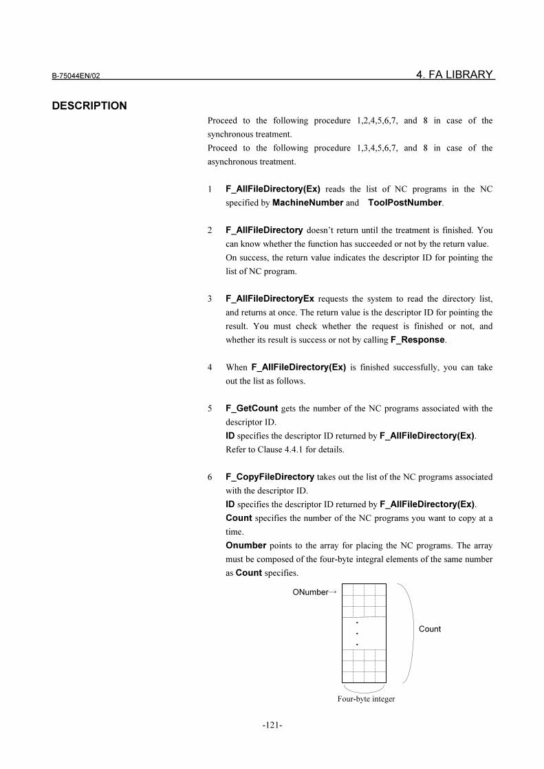
B-75044EN/02 4. FA LIBRARY
-121-
DESCRIPTION
Proceed to the following procedure 1,2,4,5,6,7, and 8 in case of the
synchronous treatment.
Proceed to the following procedure 1,3,4,5,6,7, and 8 in case of the
asynchronous treatment.
1 F_AllFileDirectory(Ex) reads the list of NC programs in the NC
specified by MachineNumber and ToolPostNumber.
2 F_AllFileDirectory doesn’t return until the treatment is finished. You
can know whether the function has succeeded or not by the return value.
On success, the return value indicates the descriptor ID for pointing the
list of NC program.
3 F_AllFileDirectoryEx requests the system to read the directory list,
and returns at once. The return value is the descriptor ID for pointing the
result. You must check whether the request is finished or not, and
whether its result is success or not by calling F_Response.
4 When F_AllFileDirectory(Ex) is finished successfully, you can take
out the list as follows.
5 F_GetCount gets the number of the NC programs associated with the
descriptor ID.
ID specifies the descriptor ID returned by F_AllFileDirectory(Ex).
Refer to Clause 4.4.1 for details.
6 F_CopyFileDirectory takes out the list of the NC programs associated
with the descriptor ID.
ID specifies the descriptor ID returned by F_AllFileDirectory(Ex).
Count specifies the number of the NC programs you want to copy at a
time.
Onumber points to the array for placing the NC programs. The array
must be composed of the four-byte integral elements of the same number
as Count specifies.
�
�
�
ONumber�
Count
Four-byte integer
4. FA LIBRARY B-75044EN/02
-122-
CopiedCount points to the four-byte integral buffer for placing the
actual copied number.
F_CopyFileDirectory takes out the NC programs from the descriptor
ID, and copies them to the array specified by ONumber.
Count specifies the number of NC programs you want to copy. The
number of the actual copied NC program number is set to
CopiedCount.
F_CopyFileDirectory can copy an NC program number with dividing
into several times. When F_CopyFileDirectory returns, the copy offset
is advanced to the next location of the actual copied NC program.
7 F_Seek can move the copy offset to the NC program you want to copy
by using F_CopyFileDirectory.
8 Call F_FreeID to free the descriptor ID when you finish the copy of NC
programs.
RETURN VALUE
F_AllFileDirectory(Ex) returns the descriptor ID of the positive integer for
pointing the list of the NC program if it succeeds. And a value of 0 is returned
if it fails.
TRUE is returned if F_CopyFileDirectory succeeds, FALSE is returned if
it fails.
In failure, an error code can be acquired by using F_GetLastError.
B-75044EN/02 4. FA LIBRARY
-123-
4.3.9 Establishing DNC1 Connection < F_EstablishDnc1 >
SYNOPSIS
In case of the synchronous treatment
VB Function EstablishDnc1 (ByVal MachineNumber As Long) As Boolean
C++ BOOL F_EstablishDnc1(LONG MachineNumber);
In case of the asynchronous treatment
VB Function EstablishDnc1Ex(ByVal MachineNumber As Long) As Long
C++ LONG F_EstablishDnc1Ex(LONG MachineNumber);
F_EstablishDnc1(Ex) indicates both of the synchronous and the
asynchronous functions.
DESCRIPTION
Proceed to the following procedure 1,2 in case of the synchronous treatment.
Proceed to the following procedure 1,3,4 in case of the asynchronous
treatment.
1 F_EstablishDnc1(Ex) establishes the DNC1 connection of the NC
specified by MachineNumber. The function is effective to the machine
registered to DNC1 in the Machine Configuration screen.
2 F_EstablishDnc1 doesn’t return until the treatment is finished. You
can know whether the function has succeeded or not by the return value.
3 F_EstablishDnc1Ex requests the system to make connection with the
NC, and returns at once. The return value is the descriptor ID for
pointing the result. You must check whether the request is finished or not,
and whether its result is success or not by calling F_Response.
4 Call F_FreeID to free the descriptor ID after getting the result of
F_EstablishDnc1Ex by calling F_Response.
RETURN VALUE
TRUE is returned if F_EstablishDnc1 succeeds, FALSE is returned if it
fails.
F_EstablishDnc1Ex returns the positive integer of the descriptor ID for
pointing the result if it succeeds. The value of 0 is returned if it fails.
In failure, an error code can be acquired when F_GetLastError is carried
out.
4. FA LIBRARY B-75044EN/02
-124-
4.3.10 Confirmation of DNC1 Connection < F_ConfirmDnc1 >
SYNOPSIS
In case of the synchronous treatment
VB Function ConfirmDnc1
(ByVal ComputerName As String, Linked As Long,
CopiedCount As Long) As Boolean
C++ BOOL F_ConfirmDnc1
(LPCTSTR ComputerName, LONG* Linked, LONG* CopiedCount);
In case of the asynchronous treatment
VB Function ConfirmDnc1Ex(ByVal ComputerName As String) As Long
C++ LONG F_ConfirmDnc1Ex(LPCTSTR ComputerName);
F_ConfirmDnc1(Ex) indicates both of the synchronous and the
asynchronous functions.
VB Function F_CopyDnc1Linked
(ByVal ID As Long, Linked As Long,
CopiedCount As Long) As Boolean
C++ BOOL F_CopyDnc1Linked(LONG ID, LONG* Linked, LONG* CopiedCount);
DESCRIPTION
Proceed to the following procedure 1 and 2 in case of the synchronous
treatment.
Proceed to the following procedure 1,3,4, and 5 in case of the asynchronous
treatment.
1 F_ConfirmDnc1(Ex) gets the list of the machines which are connected
to the computer by DNC1 and which has been established.
ComputerName specifies a computer name. When the value of
ComputerName is NULL, the function can get the machines
connected to the computer where the application program is running.
2 F_ConfirmDnc1 reads the established machines and takes out them.
Linked points to the array for placing the machine number. The array
must be composed of the 32 four-byte integral elements.
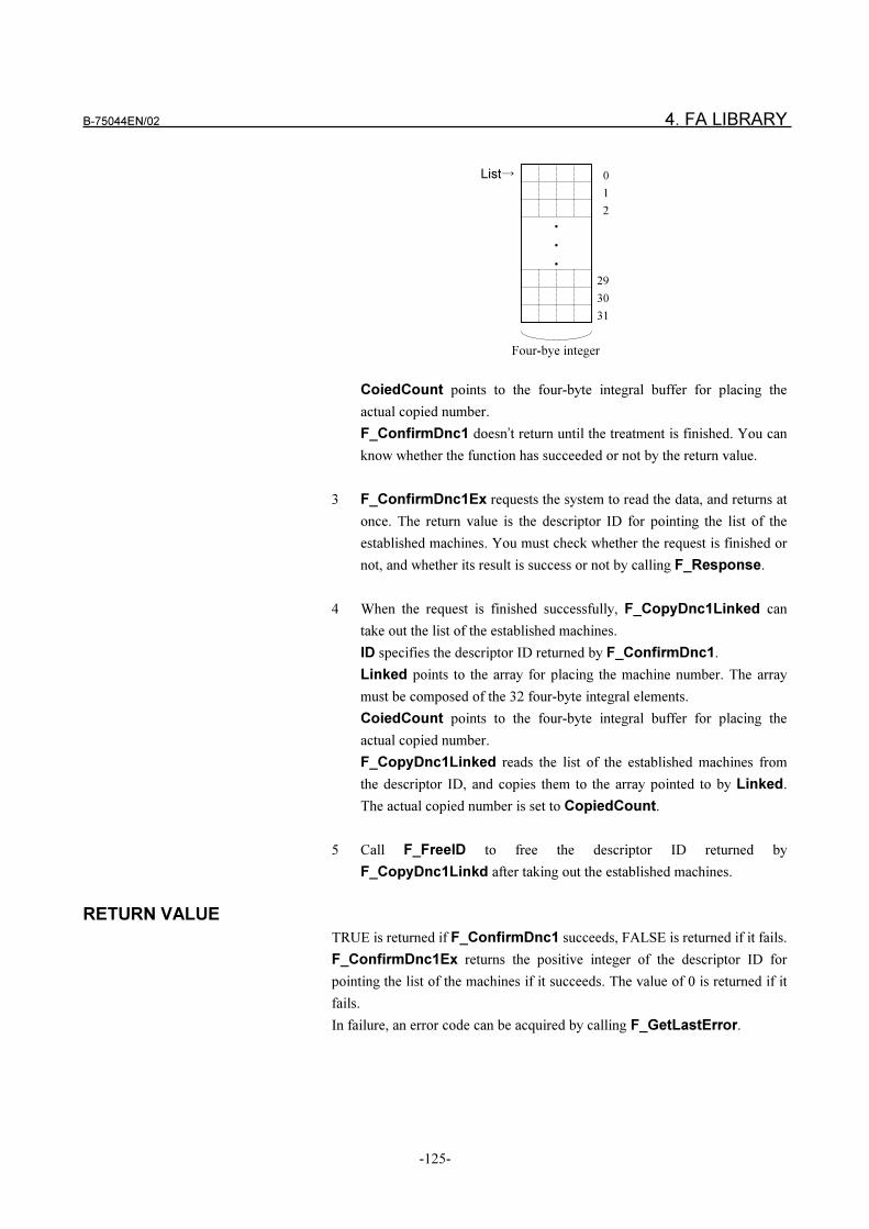
B-75044EN/02 4. FA LIBRARY
-125-
CoiedCount points to the four-byte integral buffer for placing the
actual copied number.
F_ConfirmDnc1 doesn’t return until the treatment is finished. You can
know whether the function has succeeded or not by the return value.
3 F_ConfirmDnc1Ex requests the system to read the data, and returns at
once. The return value is the descriptor ID for pointing the list of the
established machines. You must check whether the request is finished or
not, and whether its result is success or not by calling F_Response.
4 When the request is finished successfully, F_CopyDnc1Linked can
take out the list of the established machines.
ID specifies the descriptor ID returned by F_ConfirmDnc1.
Linked points to the array for placing the machine number. The array
must be composed of the 32 four-byte integral elements.
CoiedCount points to the four-byte integral buffer for placing the
actual copied number.
F_CopyDnc1Linked reads the list of the established machines from
the descriptor ID, and copies them to the array pointed to by Linked.
The actual copied number is set to CopiedCount.
5 Call F_FreeID to free the descriptor ID returned by
F_CopyDnc1Linkd after taking out the established machines.
RETURN VALUE
TRUE is returned if F_ConfirmDnc1 succeeds, FALSE is returned if it fails.
F_ConfirmDnc1Ex returns the positive integer of the descriptor ID for
pointing the list of the machines if it succeeds. The value of 0 is returned if it
fails.
In failure, an error code can be acquired by calling F_GetLastError.
�
�
�
List� 0
1
2
29
30
31
Four-bye integer
4. FA LIBRARY B-75044EN/02
-126-
4.3.11 Reading Alarm Information < F_ReadAlarm >
SYNOPSIS
In case of the synchronous treatment
VB Funciton ReadAlarm
(ByVal MachineNumber As Long, ByVal ToolPostNumber As Long,
Alarm As Long) As Boolean
C++ BOOL F_ReadAlarm
(LONG MachineNumber, LONG ToolPostNumber, LONG* Alarm);
In asynchronous treatment
VB Funciton ReadAlarmEx
(ByVal MachineNumber As Long,
ByVal ToolPostNumber As Long) As Long
C++ LONG F_ReadAlarmEx
(LONG MachineNumber, LONG ToolPostNumber);
F_ReadAlarm(Ex) indicates both of the synchronous and the asynchronous
functions.
VB Function F_CopyAlarm(ByVal ID As Long, Alarm As Long) As Boolean
C++ BOOL F_CopyAlarm(LONG ID, LONG* Alarm);
DESCRIPTION
Proceed to the following procedure 1 and 2 in case of the synchronous
treatment.
Proceed to the following procedure 1,3,4, and 5 in case of the asynchronous
treatment.
1 F_ReadAlarm(Ex) reads the alarm information of the NC specified by
MachineNumber and ToolPostNumber.
2 F_ReadAlarm reads the alarm information from NC, and sets to the
four-byte integral buffer pointed to by Alarm.
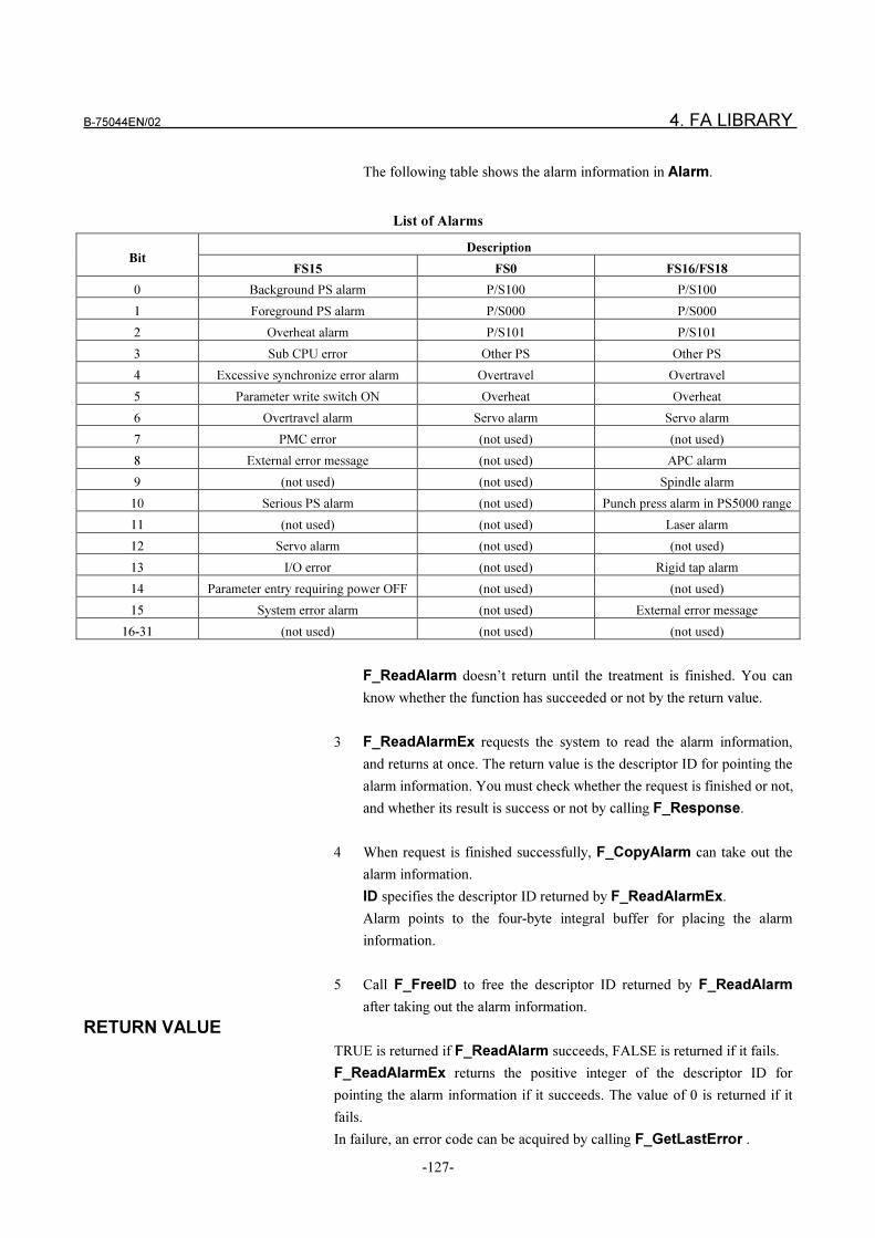
B-75044EN/02 4. FA LIBRARY
-127-
The following table shows the alarm information in Alarm.
List of Alarms
DescriptionBit
FS15 FS0 FS16/FS18
0 Background PS alarm P/S100 P/S100
1 Foreground PS alarm P/S000 P/S000
2 Overheat alarm P/S101 P/S101
3 Sub CPU error Other PS Other PS
4 Excessive synchronize error alarm Overtravel Overtravel
5 Parameter write switch ON Overheat Overheat
6 Overtravel alarm Servo alarm Servo alarm
7 PMC error (not used) (not used)
8 External error message (not used) APC alarm
9 (not used) (not used) Spindle alarm
10 Serious PS alarm (not used) Punch press alarm in PS5000 range
11 (not used) (not used) Laser alarm
12 Servo alarm (not used) (not used)
13 I/O error (not used) Rigid tap alarm
14 Parameter entry requiring power OFF (not used) (not used)
15 System error alarm (not used) External error message
16-31 (not used) (not used) (not used)
F_ReadAlarm doesn’t return until the treatment is finished. You can
know whether the function has succeeded or not by the return value.
3 F_ReadAlarmEx requests the system to read the alarm information,
and returns at once. The return value is the descriptor ID for pointing the
alarm information. You must check whether the request is finished or not,
and whether its result is success or not by calling F_Response.
4 When request is finished successfully, F_CopyAlarm can take out the
alarm information.
ID specifies the descriptor ID returned by F_ReadAlarmEx.
Alarm points to the four-byte integral buffer for placing the alarm
information.
5 Call F_FreeID to free the descriptor ID returned by F_ReadAlarm
after taking out the alarm information.
RETURN VALUE
TRUE is returned if F_ReadAlarm succeeds, FALSE is returned if it fails.
F_ReadAlarmEx returns the positive integer of the descriptor ID for
pointing the alarm information if it succeeds. The value of 0 is returned if it
fails.
In failure, an error code can be acquired by calling F_GetLastError .
4. FA LIBRARY B-75044EN/02
-128-
4.3.12 Reading Tool Offset < F_ReadToolOffset >
SYNOPSIS
VB Function ReadToolOffset
(ByVal MachineNumber As Long, ByVal ToolPostNumber As Long,
ByVal OffsetType As Long, ByVal OffsetNumber As Long,
ByVal Count As Long) As Long
C++ LONG F_ReadToolOffset
(LONG MachineNumber, LONG ToolPostNumber,
LONG OffsetType, LONG OffsetNumber, LONG Count);
The above functions run as the synchronous treatment. If you want to call
them as the asynchronous treatment, carry out ReadToolOffsetEx or
F_ReadToolOffsetEx.
(F_)ReadToolOffset and (F_)ReadToolOffsetEx have the same
arguments and the same type of the return value.
VB Function CopyToolOffset
(ByVal ID As Long, ToolOffsetValue As Long,
ToolOffsetExponent As Long) As Boolean
C++ BOOL F_CopyToolOffset
(LONG ID, LONG* ToolOffsetValue, LONG* ToolOffsetExponent);
DESCRIPTION
Proceed to the following procedure 1,2,4,5,6,7,8,9 and 10 in case of the
synchronous treatment.
Proceed to the following procedure 1,3,4,5,6,7,8,9 and 10 in case of the
asynchronous treatment.
1 F_ReadToolOffset(Ex) reads the tool offset from the NC specified by
MachineNumber and ToolPostNumber.
OffsetType specifies the type of the tool offset.
OffsetNumber specifies the start number of the tool offset you want to
read.
Count specifies the number of tool offsets you want to read at a time.
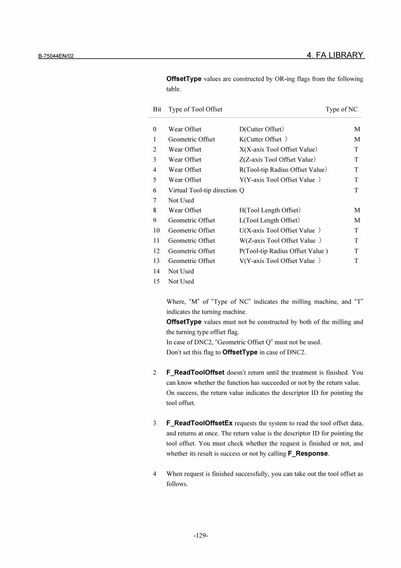
B-75044EN/02 4. FA LIBRARY
-129-
OffsetType values are constructed by OR-ing flags from the following
table.
Bit Type of Tool Offset Type of NC
0 Wear Offset D(Cutter Offset� M
1 Geometric Offset K(Cutter Offset � M
2 Wear Offset X(X-axis Tool Offset Value� T
3 Wear Offset Z(Z-axis Tool Offset Value� T
4 Wear Offset R(Tool-tip Radius Offset Value� T
5 Wear Offset Y(Y-axis Tool Offset Value � T
6 Virtual Tool-tip direction Q T
7 Not Used
8 Wear Offset H(Tool Length Offset� M
9 Geometric Offset L(Tool Length Offset� M
10 Geometric Offset U(X-axis Tool Offset Value � T
11 Geometric Offset W(Z-axis Tool Offset Value � T
12 Geometric Offset P(Tool-tip Radius Offset Value ) T
13 Geometric Offset V(Y-axis Tool Offset Value � T
14 Not Used
15 Not Used
Where, “M” of “Type of NC” indicates the milling machine, and “T”
indicates the turning machine.
OffsetType values must not be constructed by both of the milling and
the turning type offset flag.
In case of DNC2, “Geometric Offset Q” must not be used.
Don’t set this flag to OffsetType in case of DNC2.
2 F_ReadToolOffset doesn’t return until the treatment is finished. You
can know whether the function has succeeded or not by the return value.
On success, the return value indicates the descriptor ID for pointing the
tool offset.
3 F_ReadToolOffsetEx requests the system to read the tool offset data,
and returns at once. The return value is the descriptor ID for pointing the
tool offset. You must check whether the request is finished or not, and
whether its result is success or not by calling F_Response.
4 When request is finished successfully, you can take out the tool offset as
follows.
4. FA LIBRARY B-75044EN/02
-130-
5 F_CopyToolOffset copies the tool offset to the specified arrays.
ID specifies the descriptor ID returned by F_ReadToolOffset(Ex).
ToolOffsetValue points to the array for placing the tool offset value.
ToolOffsetExponent points to the array for placing the exponent of
the tool offset. Each array must be composed of 16 four-byte elements.
F_CopyToolOffset takes out one tool offset from the descriptor ID,
and F_CopyToolOffset places it in the array pointed to by
ToolOffsetValue and ToolOffsetExponent .
6 OffsetType specifies the type of tool offset with the bit flag. The
position of the bit flag(0~15) indicates the type of the tool offset as
shown at the former table. And the bit position(0~15bit) corresponds to
the element number(0~15) of array pointed to by ToolOffsetValue and
ToolOffsetExponent .
For Example, when the bit 0 of OffsetType is ON, the “Wear Offset D”
is placed in the first element of the arrays pointed to by
ToolOffsetValue and ToolOffsetExponent. No value is placed in
the other elements corresponding to the positions of inactive bits on
OffsetType.
7 The tool offset value can be calculated by substituting the contents of the
arrays pointed to by ToolOffsetValue and ToolOffsetExponent for
the following equation.
Tool offset value corresponding to the bit N =
ToolOffsetValue[N] �10^(�ToolOffsetExponent[N]�
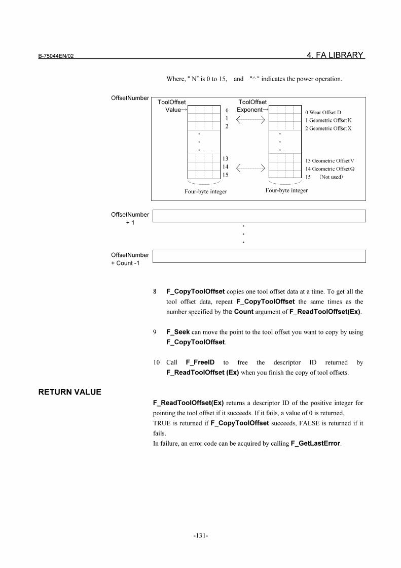
B-75044EN/02 4. FA LIBRARY
-131-
Where, “ N” is 0 to 15, and “^ “ indicates the power operation.
8 F_CopyToolOffset copies one tool offset data at a time. To get all the
tool offset data, repeat F_CopyToolOffset the same times as the
number specified by the Count argument of F_ReadToolOffset(Ex).
9 F_Seek can move the point to the tool offset you want to copy by using
F_CopyToolOffset.
10 Call F_FreeID to free the descriptor ID returned by
F_ReadToolOffset (Ex) when you finish the copy of tool offsets.
RETURN VALUE
F_ReadToolOffset(Ex) returns a descriptor ID of the positive integer for
pointing the tool offset if it succeeds. If it fails, a value of 0 is returned.
TRUE is returned if F_CopyToolOffset succeeds, FALSE is returned if it
fails.
In failure, an error code can be acquired by calling F_GetLastError.
0
1
2
13
14
15
ToolOffset
Value�
�
�
�
OffsetNumber
�
�
�
OffsetNumber
+ 1
OffsetNumber
+ Count -1
�
�
�
ToolOffset
Exponent�0 Wear Offset D
1 Geometric Offset�
2 Geometric Offset�
13 Geometric Offset�
14 Geometric Offset�
15 �Not used�
Four-byte integer Four-byte integer
4. FA LIBRARY B-75044EN/02
-132-
4.3.13 Writing Tool Offset < F_WriteToolOffset >
SYNOPSIS
VB Function CreateToolOffsetID
(ByVal MachineNumber As Long, ByVal ToolPostNumber As Long,
ByVal OffsetType As Long, ByVal OffsetNumber As Long,
ByVal Count As Long) As Long
C++ LONG F_CreateToolOffsetID
(LONG MachineNumber, LONG ToolPostNumber,
LONG OffsetType, LONG OffsetNumber, LONG Count);
VB Function SetToolOffset
(ByVal ID As Long, ToolOffsetValue As Long,
ToolOffsetExponent As Long) As Boolean
C++ BOOL F_SetToolOffset
(LONG ID, LONG* ToolOffsetValue, LONG* ToolOffsetExponent);
In case of the synchronous treatment
VB Function WriteToolOffset(ByVal ID As Long) As Boolean
C++ BOOL F_WriteToolOffset(LONG ID);
In case of the asynchronous treatment
VB Function WriteToolOffsetEx(ByVal ID As Long) As Long
C++ LONG F_WriteToolOffsetEx(LONG ID);
F_WriteToolOffset(Ex) indicates both of the synchronous and the
asynchronous functions.
DESCRIPTION
To write a tool offset data, you must go through the three procedures as
follows;
- Creating the descriptor ID for pointing the tool offset
- Setting a tool offset data on the area pointed to by the descriptor ID
- Writing it to NC
Proceed to the following procedure 1,2,4 and 5 in case of the synchronous
treatment.
Proceed to the following procedure 1,3,5,6 and 7 in case of the asynchronous
treatment.
B-75044EN/02 4. FA LIBRARY
-133-
1 F_CreateToolOffsetID creates the area for setting the tool offset data ,
and returns the descriptor ID.
MachineNumber specifies a machine number.
ToolPostNumber specifies a tool post number.
OffsetType specifies the type of the tool offset you want to write. Refer
to “4.3.12 Read Tool Offset” for meaning of OffsetType.
OffsetNumber specifies the start address of tool offset number you
want to write.
Count specifies the number of the tool offset you want to write.
2 F_SetToolOffset sets the tool offset data to the area pointed to by the
descriptor ID.
ID specifies the descriptor ID returned by F_CreateToolOffsetID.
ToolOffsetValue points to the array where the tool offset data is
written by the application program.
ToolOffsetExponent points to the array where the exponent of the
tool offset is written by the application program.
Each array must be composed of the 16 four-byte integral elements. You
set the tool offset to the arrays. Refer to “4.3.12 Reading Tool Offset” for
the way to write it to ToolOffsetValue and ToolOffsetExponent .
In case of DNC2, OffsetType values must be constructed by the
following flags.
0 bit only
0, 1 bits
0, 1, 8, 9 bits
2, 3, 4, 5, 6 bits
2, 3, 4, 5, 6, 10, 11, 12, 13 bits
3 F_SetToolOffset copies one tool offset data to the area pointed to by
the descriptor ID at a time.
To write all the tool offset data to the area, repeat F_SetToolOffset the
same times as the number specified by the Count argument of
F_CreateTool OffsetID.
4 F_WriteToolOffset(Ex) writes the tool offset data associated with the
descriptor ID.
For Example, the N-th tool offset number copied by F_SetToolOffset
is set to the N-th element of the area created by F_CreateToolOffsetID.
And the N-th data is written as the (OffsetNumber+N-1)-th address of
tool offset to the NC. Where, the range of “N” is from 1 to Count.
4. FA LIBRARY B-75044EN/02
-134-
5 F_WriteToolOffset doesn’t return until the treatment is finished. You
can know whether the function has succeeded or not by the return value.
You don’t need to free the descriptor ID returned by
F_CreateToolOffset.
6 F_WriteToolOffsetEx requests the system to write the tool offset data,
and returns at once. If F_WriteToolOffsetEx succeeds, it returns the
same descriptor ID as F_CreateToolOffset returns. Otherwise, the
value of 0 is returned. In failure, you don’t need to free the descriptor ID
returned by F_CreateToolOffset.
On success, you check whether the request is finished or not, and
whether its result is success or not by calling F_Response.
7 Call F_FreeID to free the descriptor ID returned by
F_WriteToolOffsetEx after the request is finished.
RETURN VALUE
F_CreateToolOffsetID returns the descriptor ID for pointing the tool offset
if it succeeds. If it fails, a value of 0 is returned.
TRUE is returned if F_SetToolOffset succeeds, FALSE is returned if it
fails.
TRUE is returned if F_WriteToolOffset succeeds, FALSE is returned if it
fails.
F_WriteToolOffsetEx returns the descriptor ID for pointing the result if it
succeeds. If it fails, a value of 0 is returned.
In failure, an error code can be acquired by calling F_GetLastError.
B-75044EN/02 4. FA LIBRARY
-135-
4.3.14 Reading Custom Macro Variable
< F_ReadCustomMacroVariable >
SYNOPSIS
VB Function F_ReadCustomMacroVariable
(ByVal MachineNumber As Long, ByVal ToolPostNumber As Long,
ByVal VariableNumber As Long, ByVal Count As Long) As Long
C++ LONG F_ReadCustomMacroVariable
(LONG MachineNumber, LONG ToolPostNumber,
LONG VariableNumber, LONG Count);
The above functions run as the synchronous treatment. If you want to call
them as the asynchronous treatment, carry out
ReadCustomMacroVariableEx or F_ReadCustomMacro
VariableEx.
(F_)ReadCustomMacroVariable and (F_)ReadCustomMacro
VariableToolEx have the same arguments and the same type of the return
value .
F_ReadCustomMacroVariable(Ex) indicates both of the synchronous
and the asynchronous functions.
VB Function F_CopyCustomMacroVariable
(ByVal ID As Long, VariableValue As Long,
VariableExponent As Long, ByVal Count As Long,
CopiedCount As Long) As Boolean
C++ LONG F_CopyCustomMacroVariable
(LONG ID, LONG* VariableValue, LONG* VariableExponent,
LONG Count, LONG* CopiedCount);
DESCRIPTION
Proceed to the following procedure 1,2,4,5,6,7,8 and 9 in case of the
synchronous treatment.
Proceed to the following procedure 1,3,5,6,7,8 and 9 in case of the
asynchronous treatment.
1 F_ReadCustomMacroVariable(Ex) reads the custom macro variable
from the NC specified by MachineNumber and ToolPostNumber.
VariableNumber specifies the start number of the custom macro
variable you want to read.
Count specifies the number of the custom macro variables you want to
read.
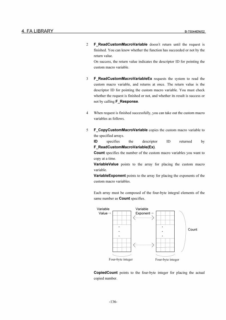
4. FA LIBRARY B-75044EN/02
-136-
2 F_ReadCustomMacroVariable doesn’t return until the request is
finished. You can know whether the function has succeeded or not by the
return value.
On success, the return value indicates the descriptor ID for pointing the
custom macro variable.
3 F_ReadCustomMacroVariableEx requests the system to read the
custom macro variable, and returns at once. The return value is the
descriptor ID for pointing the custom macro variable. You must check
whether the request is finished or not, and whether its result is success or
not by calling F_Response.
4 When request is finished successfully, you can take out the custom macro
variables as follows.
5 F_CopyCustomMacroVariable copies the custom macro variable to
the specified arrays.
ID specifies the descriptor ID returned by
F_ReadCustomMacroVariable(Ex).
Count specifies the number of the custom macro variables you want to
copy at a time.
VariableValue points to the array for placing the custom macro
variable.
VariableExponent points to the array for placing the exponents of the
custom macro variables.
Each array must be composed of the four-byte integral elements of the
same number as Count specifies.
CopiedCount points to the four-byte integer for placing the actual
copied number.
�
�
�
Variable
Value�
�
�
�
Variable
Exponent�
Count
Four-byte integer Four-byte integer
B-75044EN/02 4. FA LIBRARY
-137-
F_CopyCustomMacroVariable takes out the custom macro variables
from the descriptor ID, and places them in the array pointed to by
VariableValue and VariableExponent.
Count specifies the number of the custom macro variables you want to
copy at a time.
The actual copied number is placed in the buffer pointed to by
CopiedCount.
The custom macro variable can be calculated by substituting the contents
of the arrays pointed to by VariableValue and VariableExponent for
the following equation.
The N-th Custom Macro Variable =
VariableValue[N] �10^( � VariableExponent[N] )
Where, “ N” is from 0 to (Count � 1).
And, “^ “ indicates the power operation.
6 F_CopyCustomMacroVariable can copy several variables with
dividing into several times. When F_CopyCustomMacroVariable
returns, the copy offset is advanced to the next location of the actual
copied data.
7 F_Seek can move the copy offset to the custom macro variable you
want to copy by using F_CopyCustom MacroVariable.
8 Call F_FreeID to free the descriptor ID returned by
F_ReadCustomMacroVariable(Ex) when you finish taking out the
custom macro variables .
RETURN VALUE
F_ReadCustomMacroVariable(Ex) returns a descriptor ID for pointing
the custom macro variable if it succeeds. If it fails, a value of 0 is returned.
TRUE is returned if F_CopyCustomMacroVariable succeeds, FALSE is
returned if it fails.
In failure, an error code can be acquired when F_GetLastError is carried
out.
4. FA LIBRARY B-75044EN/02
-138-
4.3.15 Writing Custom Macro Variable < F_WriteCustomMacroVariable >
SYNOPSIS
In case of the synchronous treatment
VB Function F_WriteCustomMacroVariable
(ByVal MachineNumber As Long, ByVal ToolPostNumber As Long,
ByVal VariableNumber As Long, ByVal Count As Long,
VariableValue As Long, VariableExponent As Long) As Boolean
C++ BOOL F_WriteCustomMacroVariable
(LONG MachineNumber, LONG ToolPostNumber,
LONG VariableNumber, LONG Count, L
ONG* VariableValue, LONG* VairableValue);
In case of the asynchronous treatment
VB Function F_WriteCustomMacroVariableEx
(ByVal MachineNumber As Long, ByVal ToolPostNumber As Long,
ByVal VariableNumber As Long, ByVal Count As Long,
VariableValue As Long, VariableExponent As Long) As Long
C++ LONG F_WriteCustomMacroVariableEx
(LONG MachineNumber, LONG ToolPostNumber,
LONG VariableNumber, LONG Count,
LONG* VariableValue, LONG* VairableValue);
F_WriteCustomMacroVariable(Ex) indicates both of the synchronous
and the asynchronous functions.
DESCRIPTION
Proceed to the following procedure 1 and 2 in case of the synchronous
treatment.
Proceed to the following procedure 1,3 and 4 in case of the asynchronous
treatment.
1 F_WriteCustomMacroVariable(Ex) writes the custom macro
variable to the NC specified by MachineNumber and
ToolPostNumber.
VariableNumber specifies the start address of the custom macro
variable you want to write.
Count specifies the number of the custom macro variables you want to
write.
ToolOffsetValue and ToolOffsetExponent point to the arrays
where the custom macro variables are written.
B-75044EN/02 4. FA LIBRARY
-139-
each array must be composed of the four-byte integral elements of the
same number as Count specifies. You set the custom macro variable to
the arrays. Refer to the “4.3.14 Reading Custom Macro Variable” for the
way to write data to VariableValue and VariableExponent.
2 F_WriteCustomMacroVariable doesn’t return until the request is
finished. You can know whether the function has succeeded or not by the
return value.
3 F_WriteCustomMacroVariableEx requests the system to write the
custom macro variable, and returns at once. The return value is the
descriptor ID for pointing the result. You must check whether the request
is finished or not, and whether its result is success or not by calling
F_Response.
4 Call F_FreeID to free the descriptor ID returned by
F_WriteCustomMacroVariableEx when the request is finished.
RETURN VALUE
TRUE is returned if F_WriteCustomMacroVariable succeeds, FALSE is
returned if it fails.
F_WriteCustomMacroVariableEx returns a descriptor ID for pointing the
custom macro variable if it succeeds. If it is fails, a value of 0 is returned.
In failure, an error code can be acquired by calling F_GetLastError .
4. FA LIBRARY B-75044EN/02
-140-
4.3.16 Reading Tool Life Management Information < F_ReadToolLife >
SYNOPSIS
VB Function F_ReadToolLife
(ByVal MachineNumber As Long, ByVal ToolPostNumber As Long,
ByVal ToolGroupNumber As Long, ByVal Count As Long) As Long
C++ LONG F_ReadToolLife
(LONG MachineNumber, LONG ToolPostNumber,
LONG ToolGroupNumber, LONG Count);
The above functions run as the synchronous treatment. If you want to call
them as the asynchronous treatment, carry out ReadToolLifeEx or
F_ReadToolLifeEx.
(F_)ReadToolLife and (F_)ReadToolLifeEx have the same arguments
and the same type of the return value.
F_ReadToolLife(Ex) indicates both of the synchronous and the
asynchronous functions.
VB Function F_CopyToolLifeParameter
(ByVal ID As Long, ToolGroupNumber As Long, ToolUsed As Long,
ToolLife As Long, ToolCount As Long) As Boolean
C++ BOOL F_CopyToolLifeParameter
(LONG ID, LONG* ToolGroupNumber,
LONG* ToolUsed, LONG* ToolLife, LONG* ToolCount);
VB Function F_CopyToolLife
(ByVal ID As Long, ToolNumber As Long,
ToolLengthCompensation As Long, CutterCompensation As Long,
ToolInformation As Long, ByVal Count As Long,
CopiedCount as Long) As Boolean
C++ BOOL F_CopyToolLife
(LONG ID, LONG* ToolNumber, LONG* ToolLengthCompensation,
LONG* CutterCompensation, LONG* ToolInformation,
LONG Count, LONG* CopiedCount);
VB Function F_SeekToolLife
(ByVal ID As Long, ByVal Offset As Long) As Boolean
C++ BOOL F_SeekToolLife(LONG ID, LONG Offset);
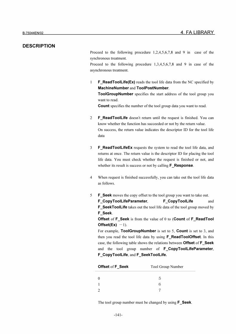
B-75044EN/02 4. FA LIBRARY
-141-
DESCRIPTION
Proceed to the following procedure 1,2,4,5,6,7,8 and 9 in case of the
synchronous treatment.
Proceed to the following procedure 1,3,4,5,6,7,8 and 9 in case of the
asynchronous treatment.
1 F_ReadToolLife(Ex) reads the tool life data from the NC specified by
MachineNumber and ToolPostNumber.
ToolGroupNumber specifies the start address of the tool group you
want to read.
Count specifies the number of the tool group data you want to read.
2 F_ReadToolLife doesn’t return until the request is finished. You can
know whether the function has succeeded or not by the return value.
On success, the return value indicates the descriptor ID for the tool life
data
3 F_ReadToolLifeEx requests the system to read the tool life data, and
returns at once. The return value is the descriptor ID for placing the tool
life data. You must check whether the request is finished or not, and
whether its result is success or not by calling F_Response.
4 When request is finished successfully, you can take out the tool life data
as follows.
5 F_Seek moves the copy offset to the tool group you want to take out.
F_CopyToolLifeParameter, F_CopyToolLife and
F_SeekToolLife takes out the tool life data of the tool group moved by
F_Seek.
Offset of F_Seek is from the value of 0 to (Count of F_ReadTool
Offset(Ex) �1).
For example, ToolGroupNumber is set to 5, Count is set to 3, and
then you read the tool life data by using F_ReadToolOffset. In this
case, the following table shows the relations between Offset of F_Seek
and the tool group number of F_CopyToolLifeParameter,
F_CopyToolLife, and F_SeekToolLife.
Offset of F_Seek Tool Group Number
0 �
1 �
2 �
The tool group number must be changed by using F_Seek.
4. FA LIBRARY B-75044EN/02
-142-
6 F_CopyToolLifeParameter takes out the information of the tool
group number specified by F_Seek.
ID specifies the descriptor ID returned by F_ReadToolLife(Ex).
ToolGroupNumber points to the buffer for placing the tool group
number.
ToolUsed points to the buffer for placing the tool life counter.
ToolLife points to the buffer for placing the tool life.
ToolCount points to the buffer for placing the number of tools.
Each buffer must be the four-byte integer.
If the specified tool group is not registered in the NC, the value of 0 is
placed in ToolUsed, ToolLife, and ToolCount .
F_CopyToolLife takes out the information of the tool which belongs
to the tool group number specified by F_Seek.
ID specifies the descriptor ID returned by F_ReadToolLife(Ex).
Count specifies the number of you want to read.
ToolLengthCompensation points to the array for placing the tool
length offset.
CutterCompensation points to the array for placing the cutter offset.
ToolInformation points to the array for placing the tool information.
Each array pointed to by ToolLengthCompensation,
CutterCompensation, and ToolInformation must be composed of
the four-byte integral elements of the same number as Count specifies.
CopiedCount points to the four-byte integral buffer for placing the
actual copied number.
F_CopyToolLife takes out the tool life information from the descriptor
ID, and places them in the arrays pointed to by
ToolLengthCompensation, Cutter Compensation and
ToolInformation.
Count specifies the number of tool life data you want to read at a time.
The actual copied number is placed in the buffer pointed to by
CopiedCount.
The following value is placed in ToolInformation .
0 : The current using tool
1 : The registered tool
2 : The tool life is run out.
3 : The tool is skipped
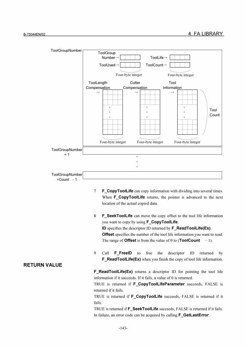
B-75044EN/02 4. FA LIBRARY
-143-
7 F_CopyToolLife can copy information with dividing into several times.
When F_CopyToolLife returns, the pointer is advanced to the next
location of the actual copied data.
8 F_SeekToolLife can move the copy offset to the tool life information
you want to copy by using F_CopyToolLife.
ID specifies the descriptor ID returned by F_ReadToolLife(Ex).
Offset specifies the number of the tool life information you want to read.
The range of Offset is from the value of 0 to (ToolCount �1).
9 Call F_FreeID to free the descriptor ID returned by
F_ReadToolLife(Ex) when you finish the copy of tool life information.
RETURN VALUE
F_ReadToolLife(Ex) returns a descriptor ID for pointing the tool life
information if it succeeds. If it fails, a value of 0 is returned.
TRUE is returned if F_CopyToolLifeParameter succeeds, FALSE is
returned if it fails.
TRUE is returned if F_CopyToolLife succeeds, FALSE is returned if it
fails.
TRUE is returned if F_SeekToolLife succeeds, FALSE is returned if it fails.
In failure, an error code can be acquired by calling F_GetLastError.
�
�
�
Cutter
Compensation
�
�
�
�
Tool
Information
�
Tool
Count
�
�
�
ToolLength
Compensation
�
�
�
�
ToolGroupNumber
+ 1
ToolGroupNumber
+Count - 1
ToolGroupNumber
Four-byte integer Four-byte integer Four-byte integer
ToolGroup
Number�
ToolUsed�
ToolLife�
ToolCount�
Four-byte integer Four-byte integer
4. FA LIBRARY B-75044EN/02
-144-
4.3.17 Reading PMC Data < F_ReadPMCData >
SYNOPSIS
VB Function F_ReadPMCData
(ByVal MachineNumber As Long, ByVal ToolPostNumber As Long,
ByVal PMCAddress As String, ByVal PMCNumber As Long,
ByVal Count As Long) As Long
C++ LONG F_ReadPMCData
(LONG MachineNumber, LONG ToolPostNumber,
LPCTSTR PMCAddress, LONG PMCNumber, LONG Count);
The above functions run as the synchronous treatment. If you want to call
them as the asynchronous treatment, carry out ReadPMCDataEx or
F_ReadPMCDataEx.
(F_)ReadPMCData and (F_)ReadPMCDataEx have the same
arguments and the same type of the return value.
F_ReadPMCData(Ex) indicates both of the synchronous and asynchronous
function.
VB Function F_CopyPMCData
(ByVal ID As Long, PMCData As Byte, ByVal Count As Long,
CopiedCount As Long) As Boolean
C++ BOOL F_CopyPMCData
(LONG ID, BYTE* PMCData, LONG Count, LONG* CopiedCount);
DESCRIPTION
Proceed to the following procedure 1,2,4,5 and 6 in case of the synchronous
treatment.
Proceed to the following procedure 1,3,4,5 and 6 in case of the asynchronous
treatment.
1 F_ReadPMCData(Ex) reads the PMC data from the NC specified by
MachineNumber and ToolPostNumber .
PMCAddress specifies the PMC address such as the one character of
“X” or “R”. And must be terminated by the NULL character.
PMCNumber specifies the start address of the PMC number.
Count specifies the number of the PMC data you want to read.
NOTE
This function cannot be used on DNC1/Ethernet. (It is scheduled to be
supported in the future.)
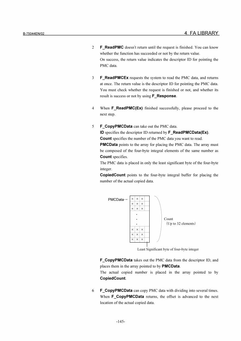
B-75044EN/02 4. FA LIBRARY
-145-
2 F_ReadPMC doesn’t return until the request is finished. You can know
whether the function has succeeded or not by the return value.
On success, the return value indicates the descriptor ID for pointing the
PMC data.
3 F_ReadPMCEx requests the system to read the PMC data, and returns
at once. The return value is the descriptor ID for pointing the PMC data.
You must check whether the request is finished or not, and whether its
result is success or not by using F_Response.
4 When F_ReadPMC(Ex) finished successfully, please proceed to the
next step.
5 F_CopyPMCData can take out the PMC data.
ID specifies the descriptor ID returned by F_ReadPMCData(Ex).
Count specifies the number of the PMC data you want to read.
PMCData points to the array for placing the PMC data. The array must
be composed of the four-byte integral elements of the same number as
Count specifies.
The PMC data is placed in only the least significant byte of the four-byte
integer.
CopiedCount points to the four-byte integral buffer for placing the
number of the actual copied data.
F_CopyPMCData takes out the PMC data from the descriptor ID, and
places them in the array pointed to by PMCData.
The actual copied number is placed in the array pointed to by
CopiedCount.
6 F_CopyPMCData can copy PMC data with dividing into several times.
When F_CopyPMCData returns, the offset is advanced to the next
location of the actual copied data.
�
�
�
PMCData�
Count
�Up to 32 elements�
�
�
�
Least Significant byte of four-byte integer
�
�
�
�
�
�
�
�
�
�
�
�
�
�
�
4. FA LIBRARY B-75044EN/02
-146-
7 F_Seek can move the copy offset to the PMC data you want to copy by
using F_CopyPMCData.
8 Call F_FreeID to free the descriptor ID returned by F_ReadPMCData
(Ex) when you finish taking out PMC data.
RETURN VALUE
F_ReadPMCData(Ex) returns a descriptor ID for pointing the PMC data if
it succeeds. If it fails, a value of 0 is returned .
TRUE is returned if F_CopyPMCData succeeds, FALSE is returned if it
fails.
In failure, an error code can be acquired when F_GetLastError is carried
out.
4.3.18 Writing PMC Data< F_WritePMCData >
SYNOPSIS
In case of the synchronous treatment
VB Function F_WritePMCData
(ByVal MachineNumber As Long, ByVal ToolPostNumber As Long,
ByVal PMCAddress As String, ByVal PMCNumber As Long,
ByVal Count As Long, PMCData As Byte) As Boolean
VC++ BOOL F_WritePMCData
(LONG MachineNumber, LONG ToolPostNumber,
LPCTSTR PMCAddress, LONG PMCNumber,
LONG Count, BYTE *PMCData );
In case of the asynchronous treatment
VB Function F_WritePMCDataEx
(ByVal MachineNumber As Long, ByVal ToolPostNumber As Long,
ByVal PMCAddress As String, ByVal PMCNumber As Long
ByVal Count As Long, PMCData As Byte) As Long
VC++ LONG F_WritePMCDataEx
(LONG MachineNumber, LONG ToolPostNumber,
LPCTSTR PMCAddress, LONG PMCNumber,
LONG Count, BYTE *PMCData );
F_WritePMCData(Ex) indicates both of the synchronous and the
asynchronous functions.
B-75044EN/02 4. FA LIBRARY
-147-
DESCRIPTION
Proceed to the following procedure 1 and 2 in case of the synchronous
treatment.
Proceed to the following procedure 1,3 and 4 in case of the asynchronous
treatment.
1 F_WritePMCData(Ex) writes the PMC data to the NC specified by
MachineNumber and ToolPostNumber.
PMCAddress specifies the PMC address such as the one character of
“R” or “D”. And must be terminated by NULL.
PMCNumber specifies the start address of the PMC number.
Count specifies the number of the PMC data you want to write. But the
maximum is “32”.
PMCData points to the array where the PMC data is written. The array
must be composed of the four-byte integral elements of the same number
as Count specifies.
You set the PMC data to PMCData. The PMC data must be set in only
the least significant byte of the four-byte integer. Three higher order
bytes must be set to the value of 0.
Refer to “Reading PMC Data” for the way to write the PMC data to
PMCData.
2 F_WritePMCData doesn’t return until the request is finished. You can
know whether the function has succeeded or not by the return value.
3 F_WritePMCEx requests the system to write the PMC data, and returns
at once. The return value is the descriptor ID for pointing the result. You
must check whether the request is finished or not, and whether its result
is success or not by using F_Response.
4 Call F_FreeID to free the descriptor ID return by F_WritePMCEx
after the request is finished.
RETURN VALUE
TRUE is returned if F_WritePMCData succeeds, FALSE is returned if it
fails.
F_WritePMCDataEx returns a descriptor ID of the positive integer for
pointing the result if it succeeds. If it fails, a value of 0 is returned.
In failure, an error code can be acquired by calling F_GetLastError.
4. FA LIBRARY B-75044EN/02
-148-
4.3.19 Reading NC Parameters < F_ReadParameter >
SYNOPSIS
VB Function ReadParameter
(ByVal MachineNumber As Long, ByVal ToolPostNumber As Long,
ByVal ParameterNumber As Long, ByVal DataFormat As Long,
ByVal ParameterAxis As Long) As Long
VC++ LONG F_ReadParameter
(LONG MachineNumber, LONG ToolPostNumber,
LONG ParameterNumber, LONG DataFormat,
LONG ParameterAxis);
The function names in the above example are for a case where processing is
carried out synchronously. The function names for when processing is carried
out asynchronously become F_ReadParameterEx. The type of argument and
return value is the same in both synchronous and asynchronous processing.
The description F_ReadParameter(Ex) indicates both synchronous and
asynchronous processing.
VB Function CopyParameter (ByVal ID As Long, Parameter As Long) As Boolean
VC++ BOOL F_CopyParameter (LONG ID, Long* Parameter);
DESCRIPTION
Proceed to 1, 2 and 4 to 7 in the case of synchronous processing.
Proceed to 1 and 3 to 7 in the case of synchronous processing.
1 F_ReadParameter(Ex) reads parameters from the NC having the machine
number specified by MachineNumber and tool post number specified by
ToolPostNumber.
For ParameterNumber, specify the number of the parameter to be read;
for DataFormat, the data format of the parameter to be read; and for
ParamaterAxis, the data of which axis to be read when the parameter to
be read is an axis type.
Set the following values according to the data format of the parameter to
be read in DataFormat.
Data Format Data Format of Parameter to be Read
1 Bit type
2 Byte type
3 Word type
4 2-word type
For details on the data format of the parameter to be read, refer to the NC
Instruction Manual.
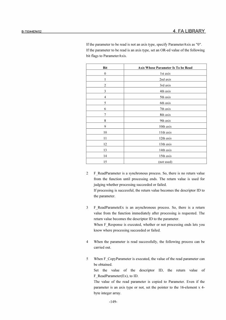
B-75044EN/02 4. FA LIBRARY
-149-
If the parameter to be read is not an axis type, specify ParameterAxis as "0".
If the parameter to be read is an axis type, set an OR-ed value of the following
bit flags to ParameterAxis.
Bit Axis Whose Parameter Is To be Read
0 1st axis
1 2nd axis
2 3rd axis
3 4th axis
4 5th axis
5 6th axis
6 7th axis
7 8th axis
8 9th axis
9 10th axis
10 11th axis
11 12th axis
12 13th axis
13 14th axis
14 15th axis
15 (not used)
2 F_ReadParameter is a synchronous process. So, there is no return value
from the function until processing ends. The return value is used for
judging whether processing succeeded or failed.
If processing is successful, the return value becomes the descriptor ID to
the parameter.
3 F_ReadParameteEx is an asynchronous process. So, there is a return
value from the function immediately after processing is requested. The
return value becomes the descriptor ID to the parameter.
When F_Response is executed, whether or not processing ends lets you
know where processing succeeded or failed.
4 When the parameter is read successfully, the following process can be
carried out.
5 When F_CopyParameter is executed, the value of the read parameter can
be obtained.
Set the value of the descriptor ID, the return value of
F_ReadParameter(Ex), to ID.
The value of the read parameter is copied to Parameter. Even if the
parameter is an axis type or not, set the pointer to the 16-element x 4-
byte integer array.
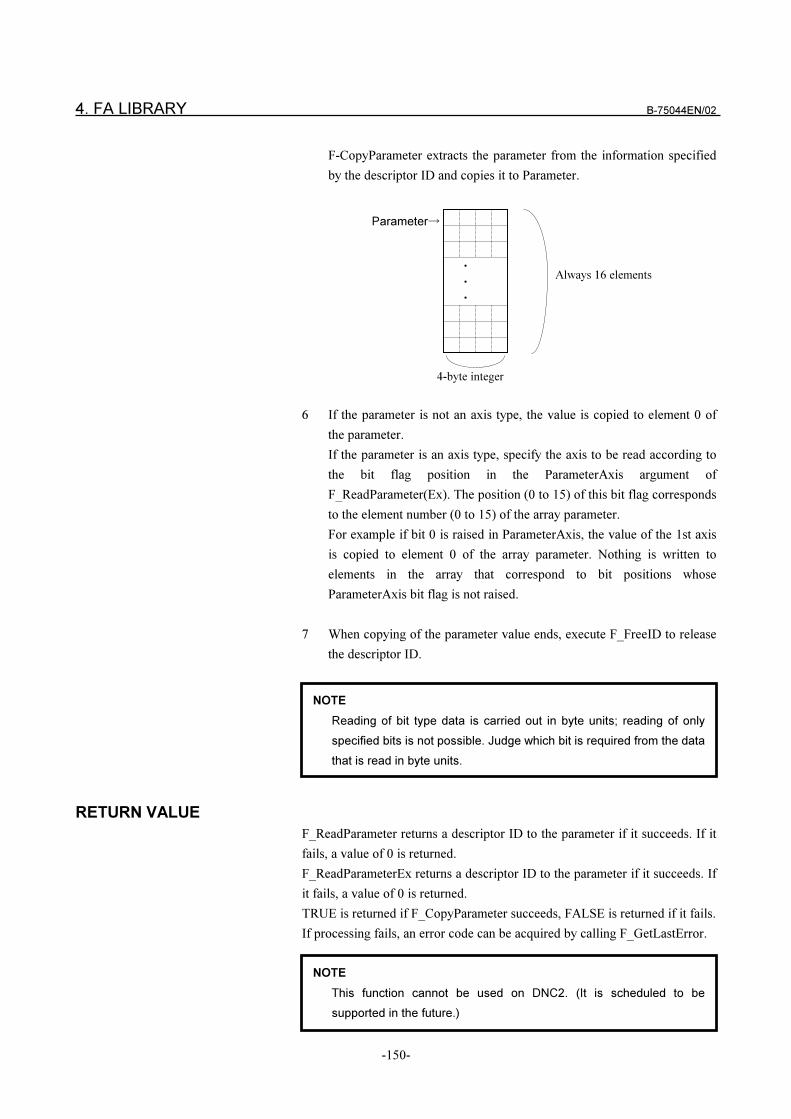
4. FA LIBRARY B-75044EN/02
-150-
F-CopyParameter extracts the parameter from the information specified
by the descriptor ID and copies it to Parameter.
6 If the parameter is not an axis type, the value is copied to element 0 of
the parameter.
If the parameter is an axis type, specify the axis to be read according to
the bit flag position in the ParameterAxis argument of
F_ReadParameter(Ex). The position (0 to 15) of this bit flag corresponds
to the element number (0 to 15) of the array parameter.
For example if bit 0 is raised in ParameterAxis, the value of the 1st axis
is copied to element 0 of the array parameter. Nothing is written to
elements in the array that correspond to bit positions whose
ParameterAxis bit flag is not raised.
7 When copying of the parameter value ends, execute F_FreeID to release
the descriptor ID.
RETURN VALUE
F_ReadParameter returns a descriptor ID to the parameter if it succeeds. If it
fails, a value of 0 is returned.
F_ReadParameterEx returns a descriptor ID to the parameter if it succeeds. If
it fails, a value of 0 is returned.
TRUE is returned if F_CopyParameter succeeds, FALSE is returned if it fails.
If processing fails, an error code can be acquired by calling F_GetLastError.
4-byte integer
�
�
�
Parameter�
Always 16 elements
NOTE
Reading of bit type data is carried out in byte units; reading of only
specified bits is not possible. Judge which bit is required from the data
that is read in byte units.
NOTE
This function cannot be used on DNC2. (It is scheduled to be
supported in the future.)
B-75044EN/02 4. FA LIBRARY
-151-
4.3.20 Writing NC Parameters < F_WriteParameter >
SYNOPSIS
In the case of synchronous processing
VB Function WriteParameter
(ByVal MachineNumber As Long, ByVal ToolPostNumber As Long,
ByVal ParameterNumber As Long, ByVal DataFormat As Long,
ByVal ParameterAxis As Long, Parameter As Long) As Boolean
VC++ BOOL F_WriteParameter
(LONG MachineNumber, LONG ToolPostNumber,
LONG ParameterNumber, LONG DataFormat,
LONG ParameterAxis, LONG *Parameter );
In the case of asynchronous processing
VB Function WriteParameterEx
(ByVal MachineNumber As Long, ByVal ToolPostNumber As Long,
ByVal ParameterNumber As Long, ByVal DataFormat As Long,
ByVal ParameterAxis As Long, Parameter As Long) As Long
VC++ LONG F_WritePMCDataEx
(LONG MachineNumber, LONG ToolPostNumber,
LONG ParameterNumber, LONG DataFormat,
LONG ParameterAxis, Long *Parameter );
The description “F_WriteParameter(Ex)” means both synchronous and
asynchronous processing.
DESCRIPTION
Read 1 and 2 in the case of synchronous processing.
Read 1, 3 and 4 in the case of synchronous processing.
1 F_WriteParameter(Ex) writes parameters to the NC having the machine
number specified by MachineNumber and tool post number specified by
ToolPostNumber.
For ParameterNumber, specify the number of the parameter to be
written; for DataFormat, the data format of the parameter to be written;
and for ParamaterAxis, the data of which axis to be written when the
parameter to be written is an axis type.
Specify the values of the parameters to be written to the NC in Parameter.
In parameter, set the pointer to the 16-element x 4-byte integer array.
For details on how to set values to DataFormat, ParameterAxis and
Parameter, see “4.3.19 Reading Parameters.”
4. FA LIBRARY B-75044EN/02
-152-
2 F_WriteParameter is a synchronous process. So, there is no return value
from the function until processing ends. The return value is used for
judging whether processing succeeded or failed.
3 F_WriteParameteEx is an asynchronous process. So, there is a return
value from the function immediately after processing is requested. The
return value becomes the descriptor ID to the processing results.
When F_Response is executed, whether or not processing ends lets you
know where processing succeeded or failed.
4 When processing ends, execute F_FreeID to release the descriptor ID.
RETURN VALUE
TRUE is returned if F_WriteParameter succeeds, FALSE is returned if it fails.
F_WriteParameterEX returns a descriptor ID to the parameter if it succeeds.
If it fails, a value of 0 is returned.
If processing fails, an error code can be acquired by calling F_GetLastError.
NOTE
Writing of bit type data is carried out in byte units; writing of only
specified bits is not possible. During writing of bit type data, read the
parameter area in which the bit to write belongs as a bit type
specification, and write that parameter as a bit type specification after
changing the bits that require changing.
NOTE
This function cannot be used on DNC2. (It is scheduled to be
supported in the future.)
B-75044EN/02 4. FA LIBRARY
-153-
4.3.21 Computer Start DNC Operation < F_Dnc... >
This function is valid only for machines connected by DNC1/Ethernet.
There are four ways of specifying the file for DNC operation as described in
section 1.3: by "file number," "file name," "NC program number" and "full
path of file." Each method has synchronous and asynchronous processing
modes.
The DNC operation procedure on the series 16i/18i:
(1) Turn the NC's DNC1 signal to ON, and then set the NC to the MEM
mode. The NC enters the RMT mode.
(2) Cycle start the NC. The MDI screen displays RMT-START.
(3) DNC operation is started on the NC by transferring the desired
program for DNC operation from your computer by the F_Dnc
function.
SYNOPSIS
<Specifying the file for DNC operation by its file number>
In the case of synchronous processing
VB Function DncFileNumber
(ByVal MachineNumber As Long, ByVal ToolPostNumber As Long,
ByVal FileNumber As Long) As Boolean
VC++ BOOL F_DncFileNumber
(LONG MachineNumber, LONG ToolPostNumber,
LONG FileNumber);
In the case of asynchronous processing
VB Function DncFileNumberEx
(ByVal MachineNumber As Long, ByVal ToolPostNumber As Long,
ByVal FileNumber As Long) As Long
VC++ LONG F_DncFileNumberEx
(LONG MachineNumber, LONG ToolPostNumber,
LONG FileNumber);
NOTE
When DNC1/Ethernet is used, DNC operation is canceled by pressing
the RESET key during DNC operation started on your computer.
Transfer is not canceled even if the RESET key is pressed on the NC
during download or upload processing for startup on your computer.
Transfer, however, can be canceled using the cancel functions
"F_DownloadCancel" and "F_UploadCancel" on your computer.
4. FA LIBRARY B-75044EN/02
-154-
<Specifying the file for DNC operation by its file name>
In the case of synchronous processing
VB Function DncFileName
(ByVal MachineNumber As Long, ByVal ToolPostNumber As Long,
ByVal FileName As String) As Boolean
VC++ BOOL F_DncFileName
(LONG MachineNumber, LONG ToolPostNumber,
LPCTSTR FileName);
In the case of asynchronous processing
VB Function DncFileNameEx
(ByVal MachineNumber As Long, ByVal ToolPostNumber As Long,
ByVal FileName As String) As Long
VC++ LONG F_DncFileNameEx
(LONG MachineNumber, LONG ToolPostNumber,
LPCTSTR FileName);
<Specifying the file for DNC operation by NC program number>
In the case of synchronous processing
VB Function DncONumber
(ByVal MachineNumber As Long, ByVal ToolPostNumber As Long,
ByVal ONumber As Long) As Boolean
VC++ BOOL F_DncONumber
(LONG MachineNumber, LONG ToolPostNumber,
LONG ONumber);
In the case of asynchronous processing
VB Function DncONumberEx
(ByVal MachineNumber As Long, ByVal ToolPostNumber As Long,
ByVal ONumber As Long) As Long
VC++ LONG F_DncONumberEx
(LONG MachineNumber, LONG ToolPostNumber,
LONG ONumber);
B-75044EN/02 4. FA LIBRARY
-155-
<Specifying the file for DNC operation by its full path>
In the case of synchronous processing
VB Function DncFilePath
(ByVal MachineNumber As Long, ByVal ToolPostNumber As Long,
ByVal FilePath As String) As Boolean
VC++ BOOL F_DncFileName
(LONG MachineNumber, LONG ToolPostNumber,
LPCTSTR FilePath);
In the case of asynchronous processing
VB Function DncFilePathEx
(ByVal MachineNumber As Long, ByVal ToolPostNumber As Long,
ByVal FilePath As String) As Long
VC++ LONG F_DncFileNameEx
(LONG MachineNumber, LONG ToolPostNumber,
LPCTSTR FilePath);
The description “F_Dnc...” indicates synchronous processing of the above
four types of functions.
The description “F_Dnc...Ex” indicates asynchronous processing of the above
four types of functions.
The description “F_Dnc...(Ex)” indicates both synchronous and asynchronous
processing.
DESCRIPTION
Read 1 and 2 in the case of synchronous processing.
Read 1, 3 and 4 in the case of synchronous processing.
1 F_Dnc...(Ex) transfers NC program files from your computer to the NC
for DNC operation. The following table shows the four ways of
specifying the file for DNC operation.
Method of Specification Name of Function
File number F_DncFileNumber(Ex)
File name F_DncFileName(Ex)
NC program number F_DncONumber(Ex)
Full path of file F_DncFilePath(Ex)
There are MachineNumber and ToolPostNumber for the common
argument.
For MachineNumber, specify the machine number.
For ToolPostNumber, specify the tool post number.
4. FA LIBRARY B-75044EN/02
-156-
At F_DncFileNumber(Ex), specify the file number by FileNumber. Any
value from 1 to 9999 can be specified.
At F_DncFileName(Ex), specify the file name by FileName.
At F_DncONumber(Ex), specify the NC program by ONumber.
At D_DncFilePath(Ex), specify the full path of the file by FilePath.
Section 1.3 describes the rules for transferring NC programs specified by
“file number,” “file name” and “NC program number.”
When files to be transferred are specified by “file order”, specified files
in ASCII sorted order are subject to DNC operation.
When files are specified by “file name,” files having the same name are
subject to DNC operation.
When files are specified by “NC program number,” files having a name
in the format “Oxxxx” (xxxx: specified NC program number) followed
by an extension are subject to DNC operation.
When files are specified by “full path of file,” files having the full
specified path are transferred regardless of the above rules.
2 F_Dnc... is a synchronous process. So, there is no return value from the
function until DNC operation ends. The return value is used for judging
whether processing succeeded or failed.
3 F_Dnc... is an synchronous process. So, there is a return value from the
function immediately after DNC operation is requested. The return value
becomes the descriptor ID to the processing results.
When F_Response is executed, whether or not processing ends lets you
know where processing succeeded or failed.
4 When processing ends, execute F_FreeID to release the descriptor ID.
RETURN VALUE
TRUE is returned if F_Dnc... succeeds, FALSE is returned if it fails.
F_Dnc...Ex returns a descriptor ID to the parameter if it succeeds. If it fails, a
value of 0 is returned.
If processing fails, an error code can be acquired by calling F_GetLastError.
B-75044EN/02 4. FA LIBRARY
-157-
4.3.22 Canceling Computer Start Download < F_DownloadCancel >
This function is valid only for machines connected by DNC1/Ethernet.
This function cancels the download that is started by starting up your
computer.
SYNOPSIS
VB Function DownloadCancel
(ByVal MachineNumber As Long, ByVal ToolPostNumber As Long)
As Boolean
VC++ BOOL F_ DownloadCancel
(LONG MachineNumber, LONG ToolPostNumber);
DESCRIPTION
1 F_DownloadCancel ends the process that was downloaded by computer
startup to the NC having the machine number specified by
MachineNumber and tool post number specified by ToolPostNumber.
2 The cancel request is reset before the download is started even if it is
started after F_DownloadCancel is executed. So, the download is not
canceled.
RETURN VALUE
TRUE is returned if F_DownloadCancel succeeds, FALSE is returned if it
fails.
If processing fails, an error code can be acquired by calling F_GetLastError.
If the specified machine is not in the process, FALSE is returned.
NOTE
1 To use this function, you must execute the download of the NC
program requested by the computer asynchronously. If the download
is executed synchronously, the application will not be returned to until
the download function ends. For this reason, the cancel function
cannot be used.
2 Processing at normal completion of this function differs from
cancellation of an actual download. Make sure that the asynchronous
download function ended by a cancel by the F_Response function
(error code 0x6000012c).
4. FA LIBRARY B-75044EN/02
-158-
4.3.23 Canceling Computer Start Upload < F_UploadCancel >
This function is valid only for machines connected by DNC1/Ethernet.
This function cancels the upload that is started by starting up your computer.
SYNOPSIS
VB Function UploadCancel
(ByVal MachineNumber As Long, ByVal ToolPostNumber As Long)
As Boolean
VC++ BOOL F_ UploadCancel (LONG MachineNumber, LONG ToolPostNumber);
DESCRIPTION
1 F_UploadCancel ends the process that was uploaded by computer startup to
the NC having the machine number specified by MachineNumber and
tool post number specified by ToolPostNumber.
2 The cancel request is reset before the upload is started even if it is started
after F_UploadCancel is executed. So, the upload is not canceled.
RETURN VALUE
TRUE is returned if F_UploadCancel succeeds, FALSE is returned if it fails.
If processing fails, an error code can be acquired by calling F_GetLastError.
If the specified machine is not in the process, FALSE is returned.
NOTE
1 To use this function, you must execute the upload of the NC program
requested by the computer asynchronously. If the upload is executed
synchronously, the application will not be returned to until the upload
function ends. For this reason, the cancel function cannot be used.
2 Processing at normal completion of this function differs from
cancellation of an actual upload. Make sure that the asynchronous
upload function ended by a cancel by the F_Response function (error
code 0x6000012c).
B-75044EN/02 4. FA LIBRARY
-159-
4.4 DIAGNOSIS AND OTHER SERVICES
4.4.1 Initialization Processing < F_Begin >
SYNOPSIS
VB Function Begin() As Boolean
VC++ BOOL F_Begin(void);
DESCRIPTION
F_ Begin executes initialization processing of this library. Execute this
function before you use this library.
RETURN VALUE
TRUE is returned if F_Begin succeeds, FALSE is returned if it fails.
If processing fails, an error code can be acquired by calling F_GetLastError.
4.4.2 Getting Number of Data < F_GetCount >
SYNOPSIS
VB Function GetCount(ByVal ID As Long, Count As Long) As Boolean
C++ BOOL F_GetCount(LONG ID, LONG* Count);
DESCRIPTION
F_GetCount counts the data associated with the descriptor ID, and places
the count number in the buffer pointed to by Count.
The contents of count data are different according to the specified descriptor
ID. Refer to the explanation of each function returning the descriptor ID.
RETURN VALUE
TRUE is returned if F_GetCount succeeds, FALSE is returned if it fails.
In failure, an error code can be acquired by calling F_GetLastError.
4. FA LIBRARY B-75044EN/02
-160-
4.4.3 Moving Offset Location of Data < F_Seek >
SYNOPSIS
VB Function Seek
(ByVal ID As Long, ByVal Offset As Long) As Boolean
C++ BOOL F_Seek(LONG ID, LONG Offset);
DESCRIPTION
F_Seek movies the offset location of the data to Offset.
The data is different according to the specified descriptor ID. Refer to the
explanation of each function returning the descriptor ID.
When the value of 0 is set to Offset, the offset location is moved to the first
data. When the (Count of F_GetCount �1) is set, it is moved to the last
data.
RETURN VALUE
TRUE is returned if F_Seek succeeds, FALSE is returned if it fails.
In failure, an error code can be acquired when F_GetLastError is carried
out.
4.4.4 Freeing Descriptor ID < F_FreeID >
SYNOPSIS
VB Sub FreeID(ByVal ID As Long)
C++ void F_FreeID(LONG ID);
DESCRIPTION
F_FreeID frees the Descriptor ID specified by ID. The descriptor ID must be
freed after using it.
After carrying out the function, you can’t access the data associated with the
freed descriptor ID.
RETURN VALUE
This function doesn’t have the return value.
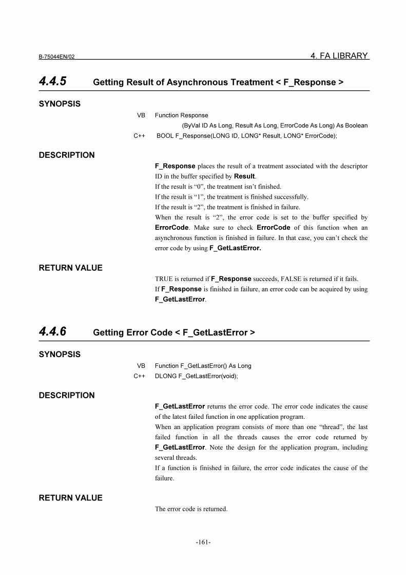
B-75044EN/02 4. FA LIBRARY
-161-
4.4.5 Getting Result of Asynchronous Treatment < F_Response >
SYNOPSIS
VB Function Response
(ByVal ID As Long, Result As Long, ErrorCode As Long) As Boolean
C++ BOOL F_Response(LONG ID, LONG* Result, LONG* ErrorCode);
DESCRIPTION
F_Response places the result of a treatment associated with the descriptor
ID in the buffer specified by Result.
If the result is “0”, the treatment isn’t finished.
If the result is “1”, the treatment is finished successfully.
If the result is “2”, the treatment is finished in failure.
When the result is “2”, the error code is set to the buffer specified by
ErrorCode. Make sure to check ErrorCode of this function when an
asynchronous function is finished in failure. In that case, you can’t check the
error code by using F_GetLastError.
RETURN VALUE
TRUE is returned if F_Response succeeds, FALSE is returned if it fails.
If F_Response is finished in failure, an error code can be acquired by using
F_GetLastError.
4.4.6 Getting Error Code < F_GetLastError >
SYNOPSIS
VB Function F_GetLastError() As Long
C++ DLONG F_GetLastError(void);
DESCRIPTION
F_GetLastError returns the error code. The error code indicates the cause
of the latest failed function in one application program.
When an application program consists of more than one “thread”, the last
failed function in all the threads causes the error code returned by
F_GetLastError. Note the design for the application program, including
several threads.
If a function is finished in failure, the error code indicates the cause of the
failure.
RETURN VALUE
The error code is returned.
4. FA LIBRARY B-75044EN/02
-162-
4.4.7 End of FA LIBRARY < F_End >
SYNOPSIS
VB Sub End()
C++ void F_End(void);
DESCRIPTION
F_End terminates FA LIBRARY. Call this function when an application
program is finished. After this function is carried out, an application program
can’t call the functions of FA LIBRARY.
RETURN VALUE
This function doesn’t have the return value.
B-75044EN/02 4. FA LIBRARY
-163-
4.5 LOG LIBRARY
This section describes the interface specifications relating to the functions
provided by the log library of FA SYSTEM for PC.
FA SYSTEM for PC creates various logs for monitoring operation. (Details of
these logs are described in “5. Monitoring FA SYSTEM for PC.”) All of these
logs are managed and created by the “LogServer” program. For this reason,
the LogServer must be started before you start FA SYSTEM for PC. The log
library starts and terminates this LogServer.
When Is Log Library required?
The log library functions are not used when FA SYSTEM for PC is started
from the [FA System] icon. This is because log library is automatically
executed to start the LogServer when the [FA System] icon is started.
To call each of the FA LIBRARY functions individually without using the
[FA System] icon (that is, to directly use the F_CreateCommunication and
F_Open functions), start the LogServer from the log library, and then use FA
LIBRARY.
Log Library Call Method
The log library is a module separate from FA LIBRARY. Start log library
from VB and VC++ as follows.
When starting from VB, the log library is supplied by “OLE Automation”. For
this reason, create an “object” by the function CreatObject(), and call the
“method” of that “object”. The name used when creating the “object” is
“LogClient.Library”.
When starting from VC++, the log library is supplied by “DLL”. The library
is not a class. For this reason, each function is called directly.
FA LIBRARY and Log Library Call Order
To call each function individually such as in the sample program without
using the [FA System] icon, start the LogServer from the log library, and use
FA LIBRARY.
To terminate the functions, terminate FA LIBRARY, and then shut down the
LogServer from the log library.
The following shows an example of how to do this in the FComTVB sample
program.
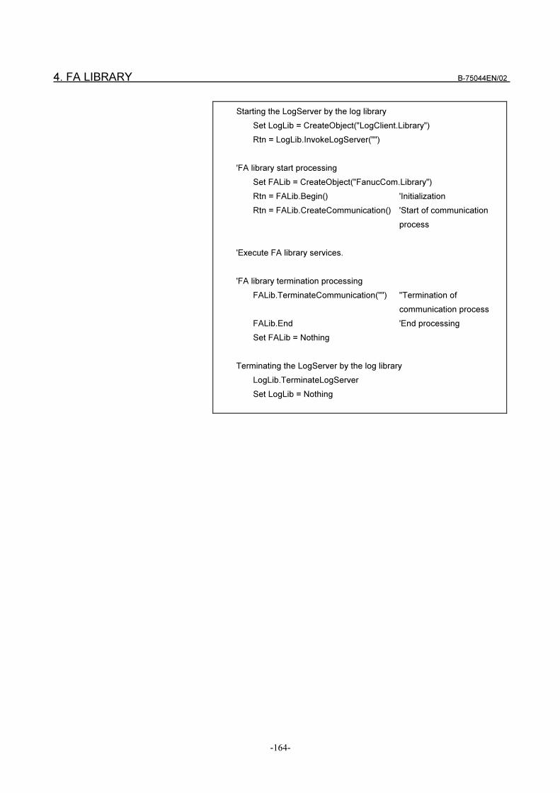
4. FA LIBRARY B-75044EN/02
-164-
Starting the LogServer by the log library
Set LogLib = CreateObject("LogClient.Library")
Rtn = LogLib.InvokeLogServer("")
'FA library start processing
Set FALib = CreateObject("FanucCom.Library")
Rtn = FALib.Begin() 'Initialization
Rtn = FALib.CreateCommunication() 'Start of communication
process
'Execute FA library services.
'FA library termination processing
FALib.TerminateCommunication("") ''Termination of
communication process
FALib.End 'End processing
Set FALib = Nothing
Terminating the LogServer by the log library
LogLib.TerminateLogServer
Set LogLib = Nothing
B-75044EN/02 4. FA LIBRARY
-165-
4.5.1 Starting LogServer < F_InvokeLogServer >
SYNOPSIS
VB Function InvokeLogServer(ByVal LogServerDir As String) As Long
VC++ LONG F_InvokeLogServer(LPCTSTR LogServerDir);
DESCRIPTION
F_InvokeLogServer starts the LogServer (LogSvr.exe).
Set "" to LogServeDir when FA SYSTEM for PC is installed and the
LogServer location has not been moved. When "" is set, the LogServer in the
installation directory of FA SYSTEM for PC is started.
(The LogServer is installed to "C: Fpfasys Bin" assuming that "C: Fpfasys" is
the directory in which FA SYSTEM for PC is installed.)
When the LogServer has been moved, set its drive name and directory name.
For example, let's assume that the LogServer has been moved to
"D:¥YourApp". In this case, set either of the following depending on whether
you programmed in VC++ or VB:
F_InvokeLogServer("D: YourApp"); (VC++)
LogLib.InvokeLogServer("D: YourApp"); (VB)
RETURN VALUE
TRUE is returned if F_InvokeLogServer succeeds, FALSE is returned if it
fails.
If processing fails, an error code can be acquired by calling F_GetLastError.
4.5.2 Terminating LogServer < F_TerminateLogServer >
SYNOPSIS
VB Function TerminateLogServer() As Boolean
VC++ BOOL F_TerminateLogServer(void);
DESCRIPTION
F_TerminateLogServer terminates the LogServer.
RETURN VALUE
TRUE is returned if F_TerminateLogServer succeeds, FALSE is returned if it
fails.
If processing fails, an error code can be acquired by calling F_GetLastError.
5. OBSERVATION OF FA SYSTEM FOR PC B-75044EN/02
-166-
5 OBSERVATION OF FA SYSTEM FOR PC
FA SYSTEM for PC reports the status of itself. When an event is occurred
and an operator needs to handle it immediately, the message appears in the
computer display. When the operator doesn’t need to handle the event at once,
the message is written in the log file without preventing him�or her from
working the job.
The Log Viewer is the tool for displaying the contents of the log file.
The Log Viewer can be started by double-clicking the [Log Viewer] program
in the [FA System for PC] group.
B-75044EN/02 5. OBSERVATION OF FA SYSTEM FOR PC
-167-
5.1 LOG VIEWER
5.1.1 About Log Message
The log messages are classified according to the source and the type of
messages as follows.
(1) Source of Messages
� FA LIBRARY
Messages related to FA LIBRARY.
The information of NC PROGRAM MANAGE-MENT is included
here because NC PROGRAM MANAGEMENT is programmed by
using FA LIBRARY.
� DNC1
Messages related to DNC1 communication.
� DNC2
Messages related to DNC2 communication.
� Reader/Puncher
Messages related to Reader/Puncher.
� DNC/Ethernet
Messages related to DNC1/Ethernet communication.
� Communication process
Messages related to the communication management.
� Database server
Messages related to the database of FA SYSTEM for PC.
(2) Type of Message
� Transmission Message
Messages related to the download/upload of NC programs.
� Error Message
Errors of FA SYSTEM for PC.
� Internal Message
The internal status of FA SYSTEM for PC.
5. OBSERVATION OF FA SYSTEM FOR PC B-75044EN/02
-168-
Therefore, there are the ten log files. (File names are put in parentheses.)
� Transmission log (TransLog)
� Error log of FA LIBRARY (FComLibErrLog)
� Internal log of FA LIBRARY (FComLibDetailLog)
� Error log of DNC1 (DNC1ErrLog)
� Internal log of DNC1 (DNC1DetailLog)
� Error log of DNC2 (DNC2ErrLog)
� Internal log of DNC2 (DNC2DetailLog)
� Error log of Reader/Puncher (RPErrLog)
� Internal log of Reader/Puncher (RPDetailLog)
� Error log of DNC1/Ethernet communication (D1EErrLog)
� Internal log of DNC1/Ethernet communication (D1EDetailLog)
� Error log of communication process (MNGErrLog)
� Internal log of communication process (MNGDetailLog)
The latest 2000 messages are saved in each log file. These files are placed in
the “LOG” sub-directory under the directory which FA SYSTEM for PC is
installed in.
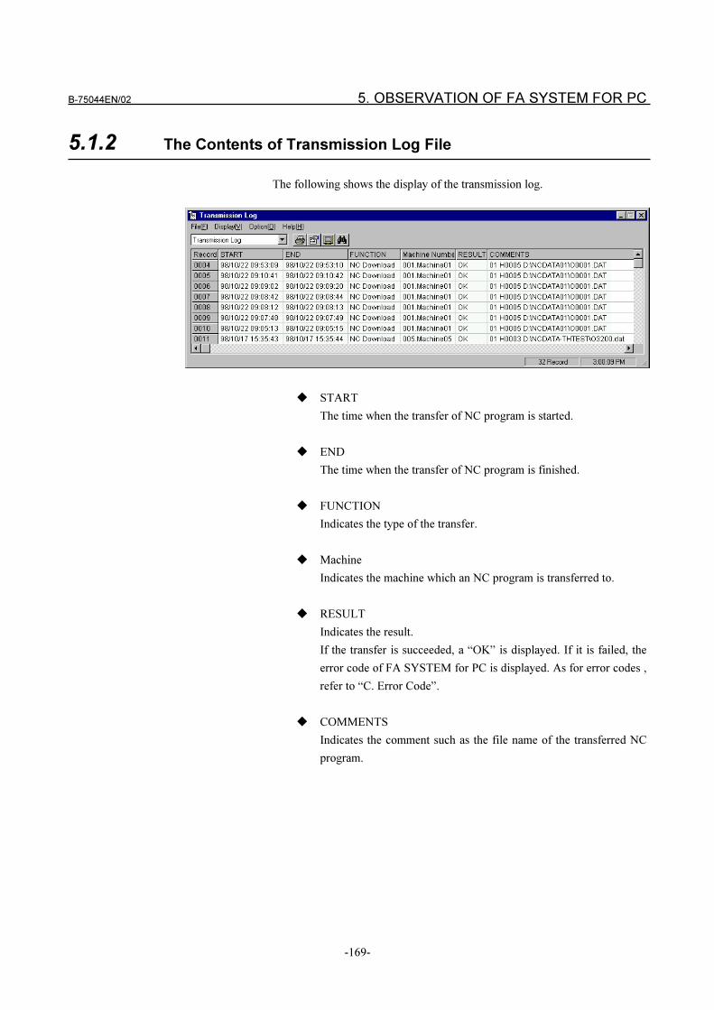
B-75044EN/02 5. OBSERVATION OF FA SYSTEM FOR PC
-169-
5.1.2 The Contents of Transmission Log File
The following shows the display of the transmission log.
� START
The time when the transfer of NC program is started.
� END
The time when the transfer of NC program is finished.
� FUNCTION
Indicates the type of the transfer.
� Machine
Indicates the machine which an NC program is transferred to.
� RESULT
Indicates the result.
If the transfer is succeeded, a “OK” is displayed. If it is failed, the
error code of FA SYSTEM for PC is displayed. As for error codes ,
refer to “C. Error Code”.
� COMMENTS
Indicates the comment such as the file name of the transferred NC
program.
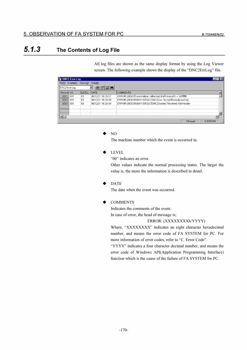
5. OBSERVATION OF FA SYSTEM FOR PC B-75044EN/02
-170-
5.1.3 The Contents of Log File
All log files are shown as the same display format by using the Log Viewer
screen. The following example shows the display of the “DNC2ErrLog” file.
� NO
The machine number which the event is occurred in.
� LEVEL
”00” indicates an error.
Other values indicate the normal processing status. The larger the
value is, the more the information is described in detail.
� DATE
The date when the event was occurred.
� COMMENTS
Indicates the comments of the event.
In case of error, the head of message is;
ERROR: (XXXXXXXXh/YYYY)
Where, “XXXXXXXX” indicates an eight character hexadecimal
number, and means the error code of FA SYSTEM for PC. For
more information of error codes, refer to “C. Error Code”.
“YYYY” indicates a four character decimal number, and means the
error code of Windows API(Application Programming Interface)
function which is the cause of the failure of FA SYSTEM for PC.
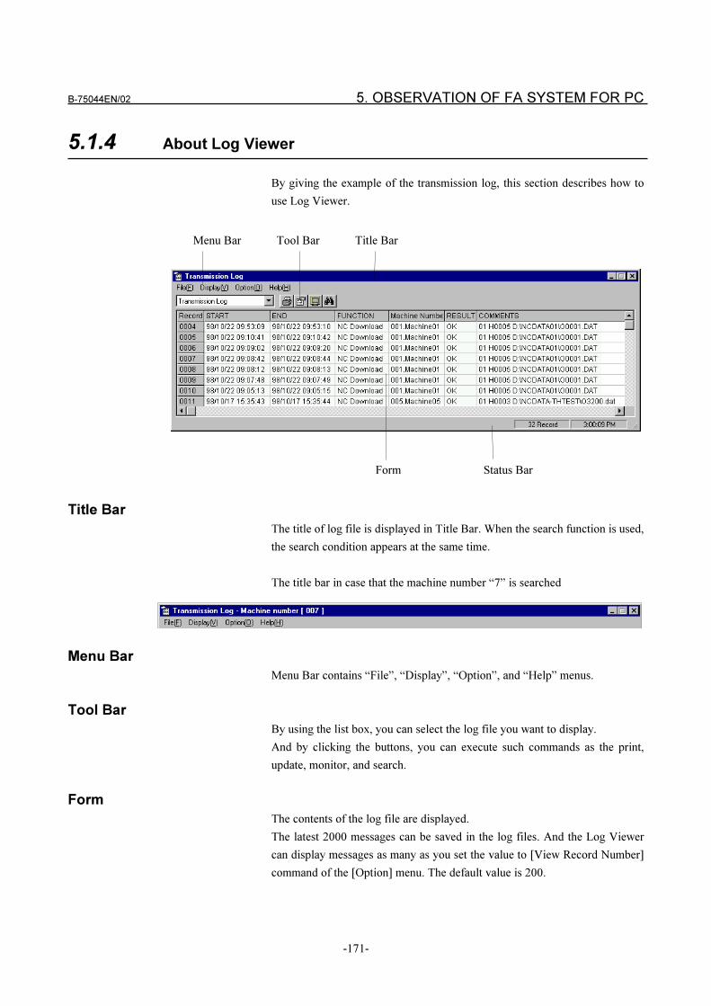
B-75044EN/02 5. OBSERVATION OF FA SYSTEM FOR PC
-171-
5.1.4 About Log Viewer
By giving the example of the transmission log, this section describes how to
use Log Viewer.
Menu Bar Tool Bar Title Bar
Form Status Bar
Title Bar
The title of log file is displayed in Title Bar. When the search function is used,
the search condition appears at the same time.
The title bar in case that the machine number “7” is searched
Menu Bar
Menu Bar contains “File”, “Display”, “Option”, and “Help” menus.
Tool Bar
By using the list box, you can select the log file you want to display.
And by clicking the buttons, you can execute such commands as the print,
update, monitor, and search.
Form
The contents of the log file are displayed.
The latest 2000 messages can be saved in the log files. And the Log Viewer
can display messages as many as you set the value to [View Record Number]
command of the [Option] menu. The default value is 200.
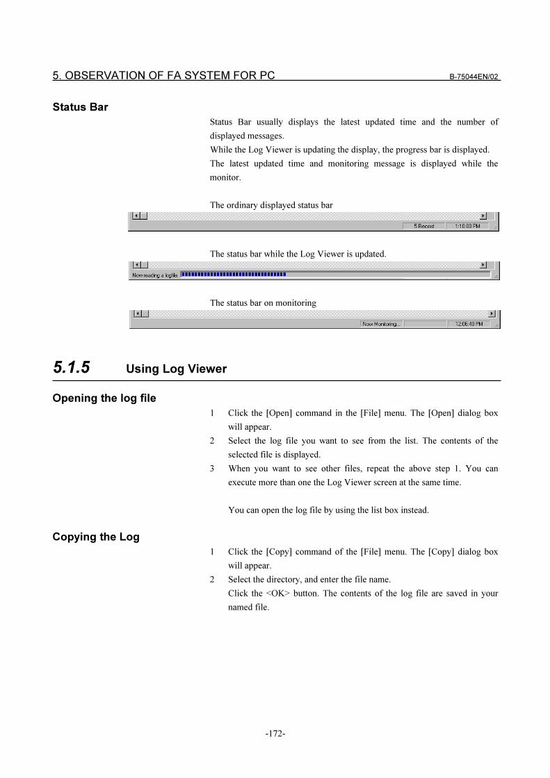
5. OBSERVATION OF FA SYSTEM FOR PC B-75044EN/02
-172-
Status Bar
Status Bar usually displays the latest updated time and the number of
displayed messages.
While the Log Viewer is updating the display, the progress bar is displayed.
The latest updated time and monitoring message is displayed while the
monitor.
The ordinary displayed status bar
The status bar while the Log Viewer is updated.
The status bar on monitoring
5.1.5 Using Log Viewer
Opening the log file
1 Click the [Open] command in the [File] menu. The [Open] dialog box
will appear.
2 Select the log file you want to see from the list. The contents of the
selected file is displayed.
3 When you want to see other files, repeat the above step 1. You can
execute more than one the Log Viewer screen at the same time.
You can open the log file by using the list box instead.
Copying the Log
1 Click the [Copy] command of the [File] menu. The [Copy] dialog box
will appear.
2 Select the directory, and enter the file name.
Click the <OK> button. The contents of the log file are saved in your
named file.
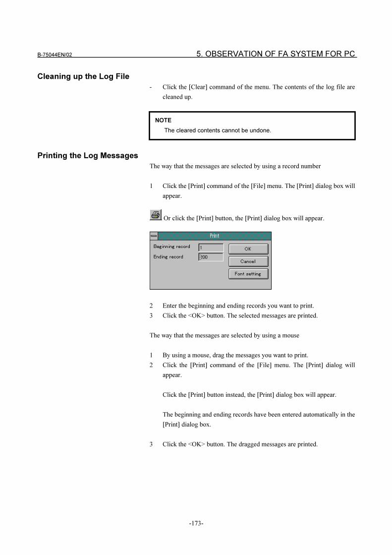
B-75044EN/02 5. OBSERVATION OF FA SYSTEM FOR PC
-173-
Cleaning up the Log File
- Click the [Clear] command of the menu. The contents of the log file are
cleaned up.
Printing the Log Messages
The way that the messages are selected by using a record number
1 Click the [Print] command of the [File] menu. The [Print] dialog box will
appear.
Or click the [Print] button, the [Print] dialog box will appear.
2 Enter the beginning and ending records you want to print.
3 Click the <OK> button. The selected messages are printed.
The way that the messages are selected by using a mouse
1 By using a mouse, drag the messages you want to print.
2 Click the [Print] command of the [File] menu. The [Print] dialog will
appear.
Click the [Print] button instead, the [Print] dialog box will appear.
The beginning and ending records have been entered automatically in the
[Print] dialog box.
3 Click the <OK> button. The dragged messages are printed.
NOTE
The cleared contents cannot be undone.
5. OBSERVATION OF FA SYSTEM FOR PC B-75044EN/02
-174-
Selecting a Font
1 Click the [Print] command in the [File] menu. The [Print] dialog will
appear.
2 Click the <Font setting> button. The [Font setting] dialog will appear.
3 Select the font you want to use.
Please select a small font size if possible.
4 Click the <OK> button. The selected font is registered.
Setting a Printer
1 Click the [Printer setting] command of the [File] menu. The [Printer
setting] dialog will appear.
2 Set up printer settings if you want. Please select a broad size paper if
possible.
3 Click the <OK> button. The printer settings are registered.
Changing the view of Tool Bar
1 Click the [Tool bar] command of the [Display] menu. The view of the
tool bar is changed.
When a check mark is set, the tool bar is displayed.
When a check mark is cleared, the tool bar is not displayed.
Changing the view of Status Bar
1 Click the [Status bar] command of the [Display] menu. The view of the
status bar is changed.
When a check mark is set, the status bar is displayed.
When a check mark is cleared, the status bar is not displayed.
Monitoring the Log Viewer
1 Click the [Monitor] command of the [Display] menu. The monitor state
of the Log Viewer is changed.
When a check mark is set, the Log Viewer updates the log information
periodically.
When a check mark is cleared, the monitoring is not executed.
Click the [Monitor] button instead. The monitoring state is changed.
NOTE
If the printer can not support the registered parameter, it is ignored.
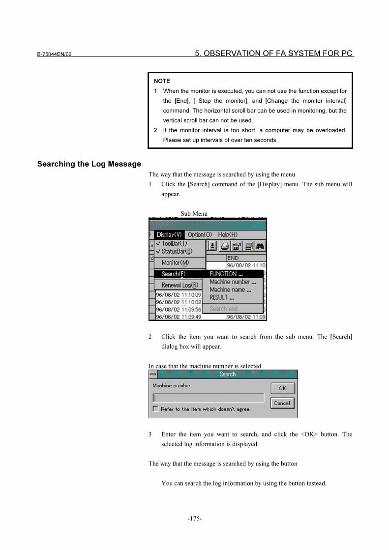
B-75044EN/02 5. OBSERVATION OF FA SYSTEM FOR PC
-175-
Searching the Log Message
The way that the message is searched by using the menu
1 Click the [Search] command of the [Display] menu. The sub menu will
appear.
Sub Menu
2 Click the item you want to search from the sub menu. The [Search]
dialog box will appear.
In case that the machine number is selected
3 Enter the item you want to search, and click the <OK> button. The
selected log information is displayed.
The way that the message is searched by using the button
You can search the log information by using the button instead.
NOTE
1 When the monitor is executed, you can not use the function except for
the [End], [ Stop the monitor], and [Change the monitor interval]
command. The horizontal scroll bar can be used in monitoring, but the
vertical scroll bar can not be used.
2 If the monitor interval is too short, a computer may be overloaded.
Please set up intervals of over ten seconds.
5. OBSERVATION OF FA SYSTEM FOR PC B-75044EN/02
-176-
Updating the Log Message
The way that the message is updated by using the menu
1 Click the [Renewal Log] command of the [Display] menu. The newest
information is displayed.
The way that the message is updated by using the button
Click the [Renewal Log] button instead. The contents of the Log Viewer
are updated automatically.
Setting the Monitor Interval
1 Click the [Monitor Interval] command of the [Option] menu. The
[Monitor interval] dialog box will appear.
2 Enter the interval, and click the <OK> button. The interval value is
registered. The value ranges from one second to 120 seconds.
Setting the Number of Messages
1 Click the [View Record Number] command in the [Option] menu. The
[View Record Number] dialog box will appear.
2 Enter the number of messages, and click the <OK> button. The value is
registered. The value ranges from one message to 2000 messages.
NOTE
The search command can search the log information displayed in the
Log Viewer.
Note that all contents of the log file are not searched.
NOTE
1 If the monitor interval is too short, a computer may be overloaded.
Please set up the interval of over ten seconds.
2 The interval can be set for each Log Viewer.
NOTE
1 If the number of messages is too many, a computer may be
overloaded. Please set up a number under 200 messages.
2 The value can be set for each Log Viewer.
B-75044EN/02 5. OBSERVATION OF FA SYSTEM FOR PC
-177-
5.2 LogServer
The LogServer receives the various log writing requests on the FA SYSTEM
for PC and creates a log file.
5.2.1 Setting log creation ON/OFF
LogServer allows you to set whether or not to create log files for each log. If
you execute FA LIBRARY functions in short cycles, the load placed on the
PC is increased as detailed logs for the FA LIBRARY and communication
process are frequently created. If this happens, you can reduce the load placed
on the system by not creating detailed logs, and creating only error logs.
If you disable the creation of detailed logs, the settings will be reflected
immediately without the need to restart FA SYSTEM for PC. The settings are
saved, so the settings are valid even when FA SYSTEM for PC is started next.
The procedure for setting log creation ON/OFF by Log Server is as follows:
1 The LogServer that was started as an icon is displayed as a window.
2 Expand the tree view to display the log name.
3 A log having a log name prefixed by “(*)” will be created.
Each click turns the display of the “*” ON and OFF, and switches
creation of the log ON and OFF. When you have finished setting log
creation, return the LogServer to its original icon.
NOTE
If you set LogServer so that a detailed log is not created, you may not
be able to parse the details of operation that was being carried out
when the error occurred. Check operation thoroughly before you
disable the creation of detailed logs.
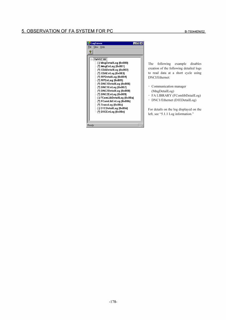
5. OBSERVATION OF FA SYSTEM FOR PC B-75044EN/02
-178-
The following example disables
creation of the following detailed logs
to read data at a short cycle using
DNCI/Ethernet:
� Communication manager
(MngDetailLog)
� FA LIBRARY (FComlibDetailLog)
� DNC1/Ethernet (D1EDetailLog)
For details on the log displayed on the
left, see “5.1.1 Log information.”
B-75044EN/02 6. LIST FILE MANAGEMENT
-179-
6 LIST FILE MANAGEMENT
Two or more NC programs can be registered to a List File and transferred.
(For details on the List File transfer function, refer to “1.6 List File Transfer
Function.”)
Two screens are provided for managing List Files:
1 Edit List File screen
Screen for creating and editing List Files
2 List File Monitor screen
Screen for monitoring transfers made using List Files.
The chapter describes how to operate from these screens.
NOTE
Transfer by List File can be used only when the Reader/Puncher
interface protocol is in use.
6. LIST FILE MANAGEMENT B-75044EN/02
-180-
6.1 EDIT LIST FILE SCREEN OPERATIONS
The Edit List File screen is where you create and edit List Files.
To display the Edit List File screen, start [Edit List Files] in the [FANUC FA
System for PC] group dialog box.
You can also start [Edit List Files] from the NC PROGRAM
MANAGEMENT screen.
6.1.1 Structure of Edit List File Screen
The figure below shows the Edit List File screen and details when
LIST001.LST List File for machine number 1 is being edited.
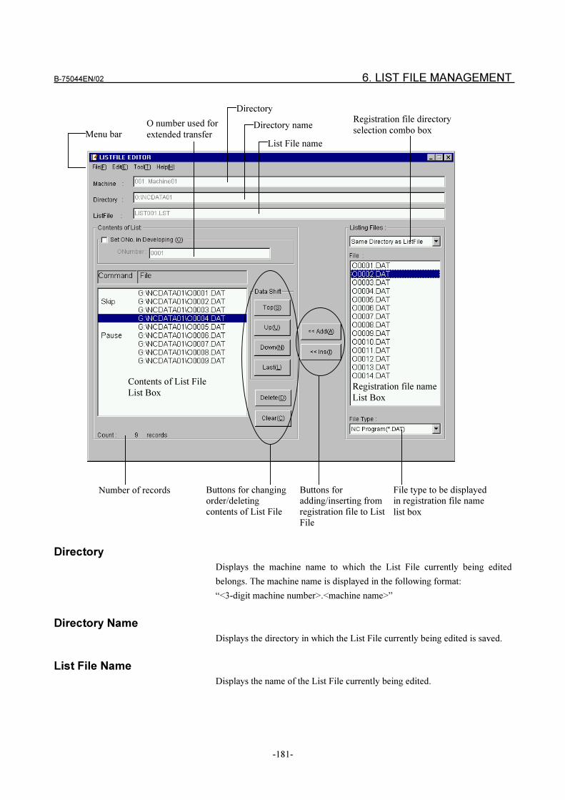
B-75044EN/02 6. LIST FILE MANAGEMENT
-181-
Directory
Displays the machine name to which the List File currently being edited
belongs. The machine name is displayed in the following format:
“<3-digit machine number>.<machine name>”
Directory Name
Displays the directory in which the List File currently being edited is saved.
List File Name
Displays the name of the List File currently being edited.
Directory
List File name
Directory nameRegistration file directory
selection combo box
Contents of List File
List BoxRegistration file name
List Box
File type to be displayedin registration file name
list box
Buttons for changingorder/deleting
contents of List File
Buttons foradding/inserting from
registration file to List
File
Menu bar
O number used for
extended transfer
Number of records
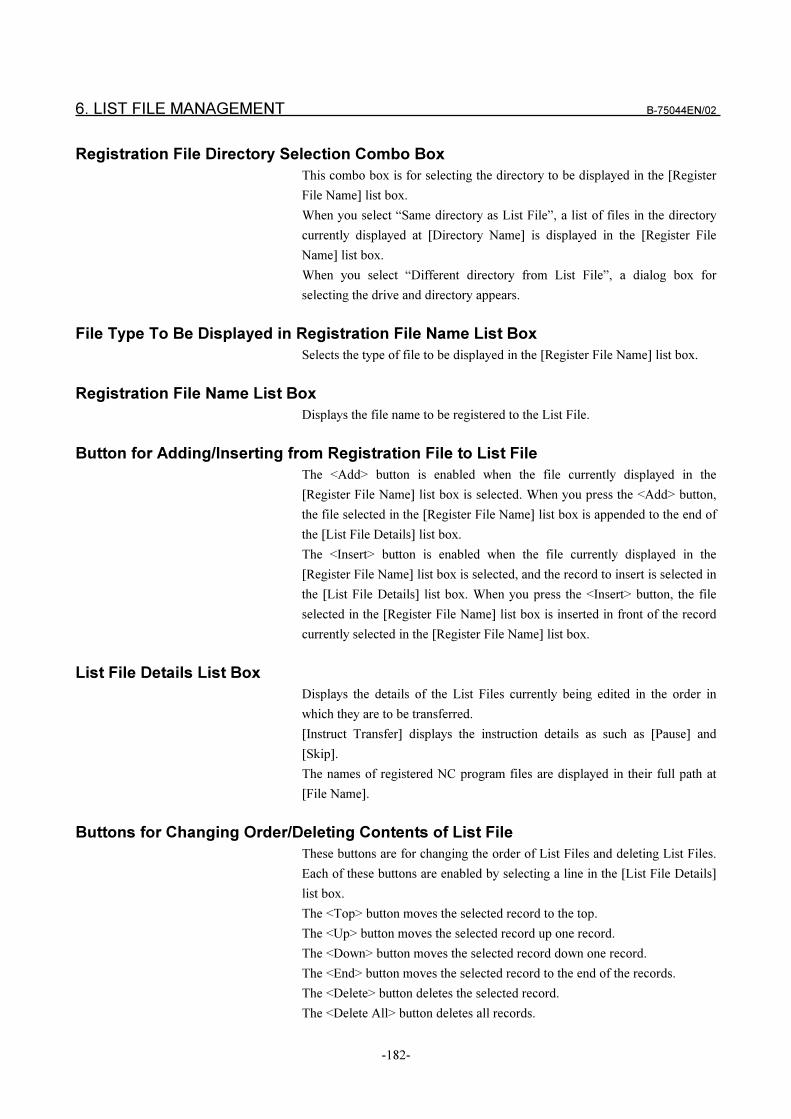
6. LIST FILE MANAGEMENT B-75044EN/02
-182-
Registration File Directory Selection Combo Box
This combo box is for selecting the directory to be displayed in the [Register
File Name] list box.
When you select “Same directory as List File”, a list of files in the directory
currently displayed at [Directory Name] is displayed in the [Register File
Name] list box.
When you select “Different directory from List File”, a dialog box for
selecting the drive and directory appears.
File Type To Be Displayed in Registration File Name List Box
Selects the type of file to be displayed in the [Register File Name] list box.
Registration File Name List Box
Displays the file name to be registered to the List File.
Button for Adding/Inserting from Registration File to List File
The <Add> button is enabled when the file currently displayed in the
[Register File Name] list box is selected. When you press the <Add> button,
the file selected in the [Register File Name] list box is appended to the end of
the [List File Details] list box.
The <Insert> button is enabled when the file currently displayed in the
[Register File Name] list box is selected, and the record to insert is selected in
the [List File Details] list box. When you press the <Insert> button, the file
selected in the [Register File Name] list box is inserted in front of the record
currently selected in the [Register File Name] list box.
List File Details List Box
Displays the details of the List Files currently being edited in the order in
which they are to be transferred.
[Instruct Transfer] displays the instruction details as such as [Pause] and
[Skip].
The names of registered NC program files are displayed in their full path at
[File Name].
Buttons for Changing Order/Deleting Contents of List File
These buttons are for changing the order of List Files and deleting List Files.
Each of these buttons are enabled by selecting a line in the [List File Details]
list box.
The <Top> button moves the selected record to the top.
The <Up> button moves the selected record up one record.
The <Down> button moves the selected record down one record.
The <End> button moves the selected record to the end of the records.
The <Delete> button deletes the selected record.
The <Delete All> button deletes all records.
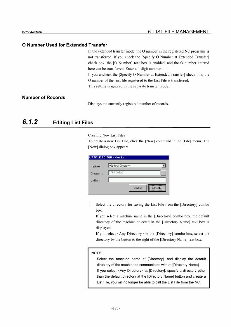
B-75044EN/02 6. LIST FILE MANAGEMENT
-183-
O Number Used for Extended Transfer
In the extended transfer mode, the O number in the registered NC programs is
not transferred. If you check the [Specify O Number at Extended Transfer]
check box, the [O Number] text box is enabled, and the O number entered
here can be transferred. Enter a 4-digit number.
If you uncheck the [Specify O Number at Extended Transfer] check box, the
O number of the first file registered to the List File is transferred.
This setting is ignored in the separate transfer mode.
Number of Records
Displays the currently registered number of records.
6.1.2 Editing List Files
Creating New List Files
To create a new List File, click the [New] command in the [File] menu. The
[New] dialog box appears.
1 Select the directory for saving the List File from the [Directory] combo
box.
If you select a machine name in the [Directory] combo box, the default
directory of the machine selected in the [Directory Name] text box is
displayed.
If you select <Any Directory> in the [Directory] combo box, select the
directory by the button to the right of the [Directory Name] text box.
NOTE
Select the machine name at [Directory], and display the default
directory of the machine to communicate with at [Directory Name].
If you select <Any Directory> at [Directory], specify a directory other
than the default directory at the [Directory Name] button and create a
List File, you will no longer be able to call the List File from the NC.
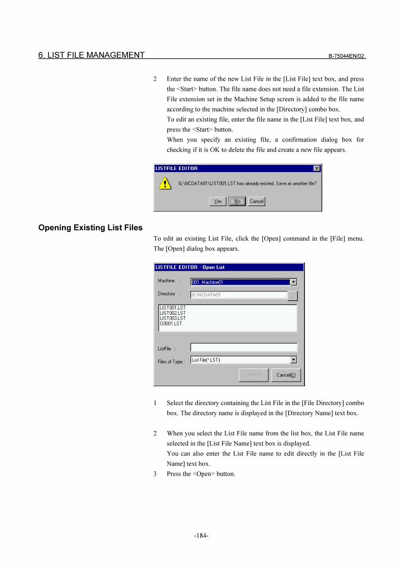
6. LIST FILE MANAGEMENT B-75044EN/02
-184-
2 Enter the name of the new List File in the [List File] text box, and press
the <Start> button. The file name does not need a file extension. The List
File extension set in the Machine Setup screen is added to the file name
according to the machine selected in the [Directory] combo box.
To edit an existing file, enter the file name in the [List File] text box, and
press the <Start> button.
When you specify an existing file, a confirmation dialog box for
checking if it is OK to delete the file and create a new file appears.
Opening Existing List Files
To edit an existing List File, click the [Open] command in the [File] menu.
The [Open] dialog box appears.
1 Select the directory containing the List File in the [File Directory] combo
box. The directory name is displayed in the [Directory Name] text box.
2 When you select the List File name from the list box, the List File name
selected in the [List File Name] text box is displayed.
You can also enter the List File name to edit directly in the [List File
Name] text box.
3 Press the <Open> button.
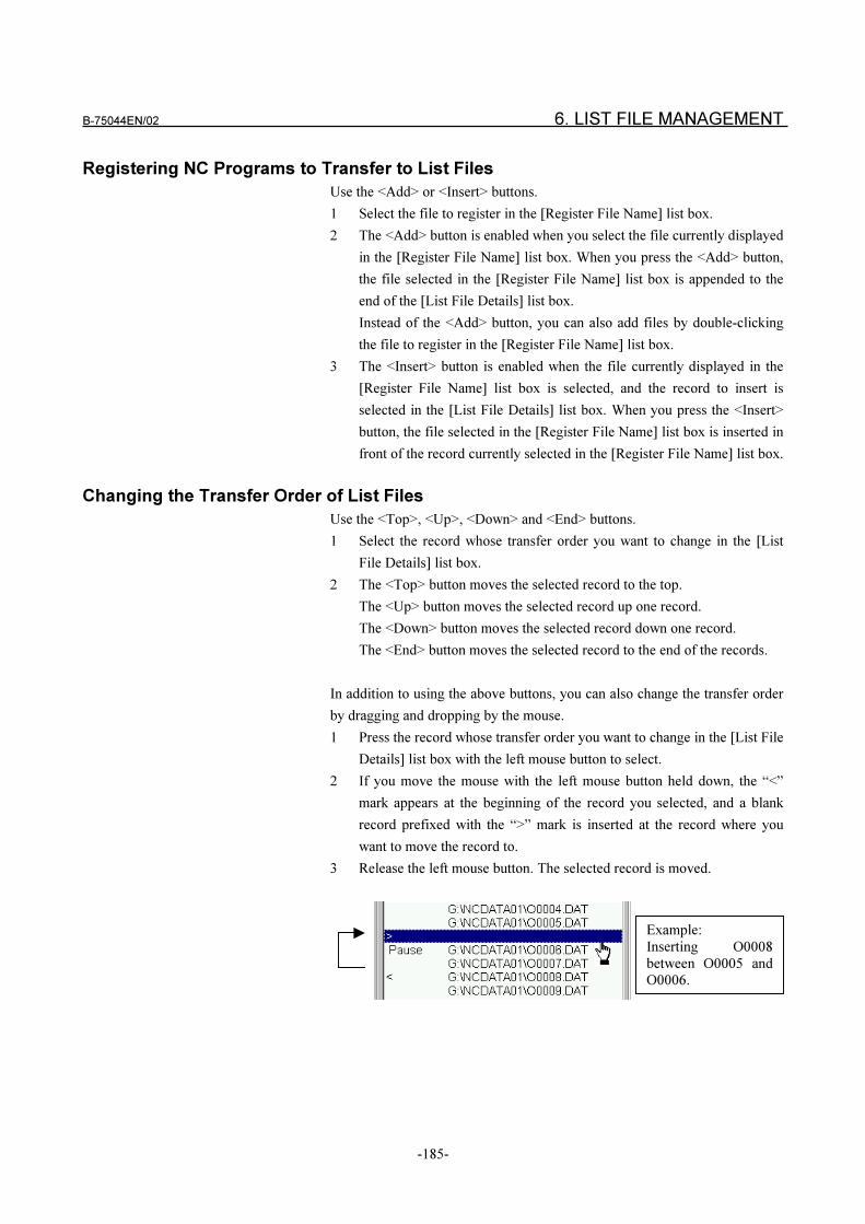
B-75044EN/02 6. LIST FILE MANAGEMENT
-185-
Registering NC Programs to Transfer to List Files
Use the <Add> or <Insert> buttons.
1 Select the file to register in the [Register File Name] list box.
2 The <Add> button is enabled when you select the file currently displayed
in the [Register File Name] list box. When you press the <Add> button,
the file selected in the [Register File Name] list box is appended to the
end of the [List File Details] list box.
Instead of the <Add> button, you can also add files by double-clicking
the file to register in the [Register File Name] list box.
3 The <Insert> button is enabled when the file currently displayed in the
[Register File Name] list box is selected, and the record to insert is
selected in the [List File Details] list box. When you press the <Insert>
button, the file selected in the [Register File Name] list box is inserted in
front of the record currently selected in the [Register File Name] list box.
Changing the Transfer Order of List Files
Use the <Top>, <Up>, <Down> and <End> buttons.
1 Select the record whose transfer order you want to change in the [List
File Details] list box.
2 The <Top> button moves the selected record to the top.
The <Up> button moves the selected record up one record.
The <Down> button moves the selected record down one record.
The <End> button moves the selected record to the end of the records.
In addition to using the above buttons, you can also change the transfer order
by dragging and dropping by the mouse.
1 Press the record whose transfer order you want to change in the [List File
Details] list box with the left mouse button to select.
2 If you move the mouse with the left mouse button held down, the “<”
mark appears at the beginning of the record you selected, and a blank
record prefixed with the “>” mark is inserted at the record where you
want to move the record to.
3 Release the left mouse button. The selected record is moved.
Example:
Inserting O0008
between O0005 andO0006.
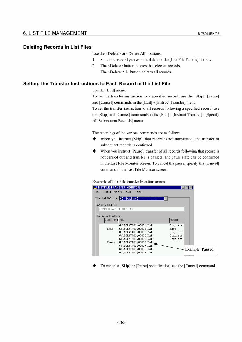
6. LIST FILE MANAGEMENT B-75044EN/02
-186-
Deleting Records in List Files
Use the <Delete> or <Delete All> buttons.
1 Select the record you want to delete in the [List File Details] list box.
2 The <Delete> button deletes the selected records.
The <Delete All> button deletes all records.
Setting the Transfer Instructions to Each Record in the List File
Use the [Edit] menu.
To set the transfer instruction to a specified record, use the [Skip], [Pause]
and [Cancel] commands in the [Edit] - [Instruct Transfer] menu.
To set the transfer instruction to all records following a specified record, use
the [Skip] and [Cancel] commands in the [Edit] - [Instruct Transfer] - [Specify
All Subsequent Records] menu.
The meanings of the various commands are as follows:
� When you instruct [Skip], that record is not transferred, and transfer of
subsequent records is continued.
� When you instruct [Pause], transfer of all records following that record is
not carried out and transfer is paused. The pause state can be confirmed
in the List File Monitor screen. To cancel the pause, specify the [Cancel]
command in the List File Monitor screen.
Example of List File transfer Monitor screen
Example: Paused
� To cancel a [Skip] or [Pause] specification, use the [Cancel] command.
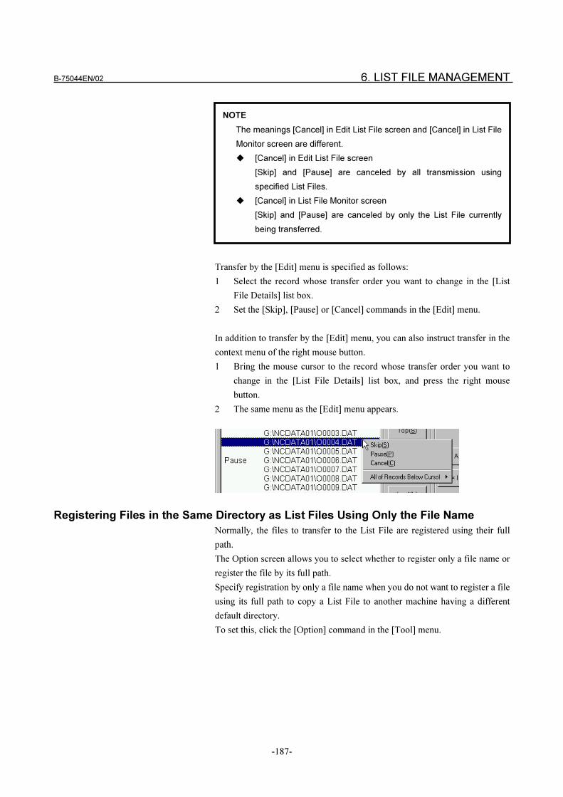
B-75044EN/02 6. LIST FILE MANAGEMENT
-187-
Transfer by the [Edit] menu is specified as follows:
1 Select the record whose transfer order you want to change in the [List
File Details] list box.
2 Set the [Skip], [Pause] or [Cancel] commands in the [Edit] menu.
In addition to transfer by the [Edit] menu, you can also instruct transfer in the
context menu of the right mouse button.
1 Bring the mouse cursor to the record whose transfer order you want to
change in the [List File Details] list box, and press the right mouse
button.
2 The same menu as the [Edit] menu appears.
Registering Files in the Same Directory as List Files Using Only the File Name
Normally, the files to transfer to the List File are registered using their full
path.
The Option screen allows you to select whether to register only a file name or
register the file by its full path.
Specify registration by only a file name when you do not want to register a file
using its full path to copy a List File to another machine having a different
default directory.
To set this, click the [Option] command in the [Tool] menu.
NOTE
The meanings [Cancel] in Edit List File screen and [Cancel] in List File
Monitor screen are different.
� [Cancel] in Edit List File screen
[Skip] and [Pause] are canceled by all transmission using
specified List Files.
� [Cancel] in List File Monitor screen
[Skip] and [Pause] are canceled by only the List File currently
being transferred.
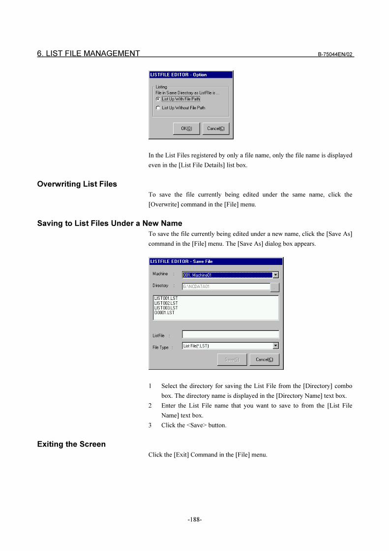
6. LIST FILE MANAGEMENT B-75044EN/02
-188-
In the List Files registered by only a file name, only the file name is displayed
even in the [List File Details] list box.
Overwriting List Files
To save the file currently being edited under the same name, click the
[Overwrite] command in the [File] menu.
Saving to List Files Under a New Name
To save the file currently being edited under a new name, click the [Save As]
command in the [File] menu. The [Save As] dialog box appears.
1 Select the directory for saving the List File from the [Directory] combo
box. The directory name is displayed in the [Directory Name] text box.
2 Enter the List File name that you want to save to from the [List File
Name] text box.
3 Click the <Save> button.
Exiting the Screen
Click the [Exit] Command in the [File] menu.
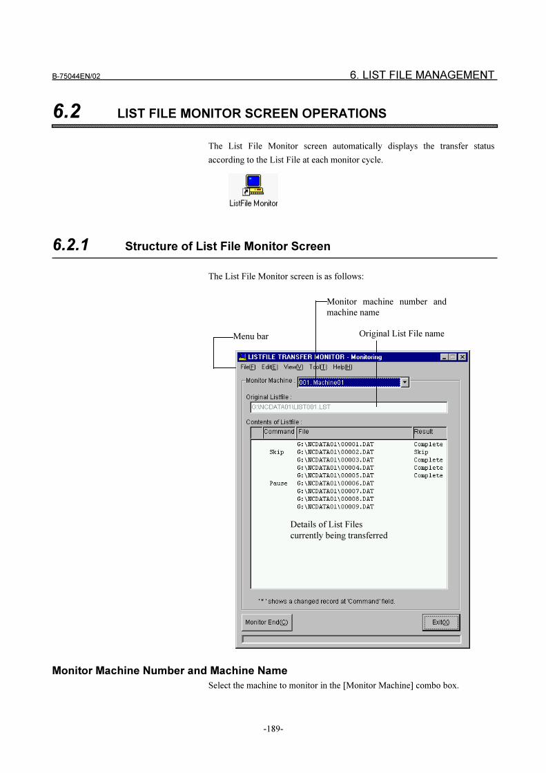
B-75044EN/02 6. LIST FILE MANAGEMENT
-189-
6.2 LIST FILE MONITOR SCREEN OPERATIONS
The List File Monitor screen automatically displays the transfer status
according to the List File at each monitor cycle.
6.2.1 Structure of List File Monitor Screen
The List File Monitor screen is as follows:
Monitor machine number and
machine name
Details of List Files
currently being transferred
Menu bar Original List File name
Monitor Machine Number and Machine Name
Select the machine to monitor in the [Monitor Machine] combo box.
6. LIST FILE MANAGEMENT B-75044EN/02
-190-
Original List File Name
The List File name created in the Edit List File screen is displayed.
Nothing is displayed if a List File is not being transferred.
Details of List Files Currently Being Transferred
This screen monitors and displays the status of List Files currently being
transferred at each monitor cycle described later.
� Transfer instruction
Displays the transfer instruction set in the Edit List File screen.
� File name
Displays the file name set in the Edit List File screen. The displayed
order is the transfer order.
� Transfer results
Displays the current transfer status:
“Transferred” Transfer of this record has ended.
“Skipped” This record has not been transferred, and the next record
has been processed.
“Paused” This record has not been transferred, and transfer has
been paused.
Specify [Cancel] to resume transfer.
Nothing is displayed if a List File is not being transferred.
6.2.2 List File Monitor Operations
Changing the Monitor Machine
Select the machine to monitor in the [Monitor Machine] combo box.
Changing the Monitor Cycle
If you execute the [Set Monitor Cycle] in the [Display] menu, the [Monitor
Cycle] dialog box appears. Drag the slider to change the monitor cycle, and
press the <OK> button.
The monitor cycle default is 10 seconds.
Updating to Latest Monitor Information
If you execute the [Set Monitor Cycle] in the [Display] menu, the latest
monitor information is displayed regardless of the monitor cycle.
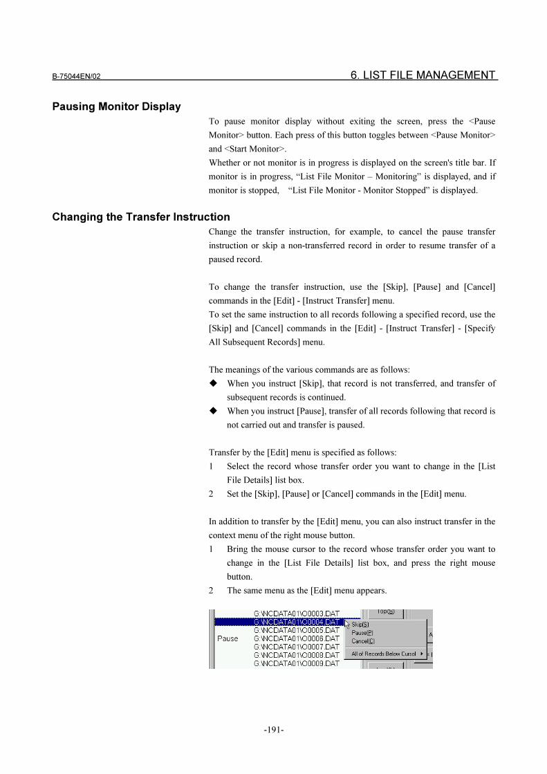
B-75044EN/02 6. LIST FILE MANAGEMENT
-191-
Pausing Monitor Display
To pause monitor display without exiting the screen, press the <Pause
Monitor> button. Each press of this button toggles between <Pause Monitor>
and <Start Monitor>.
Whether or not monitor is in progress is displayed on the screen's title bar. If
monitor is in progress, “List File Monitor – Monitoring” is displayed, and if
monitor is stopped, “List File Monitor - Monitor Stopped” is displayed.
Changing the Transfer Instruction
Change the transfer instruction, for example, to cancel the pause transfer
instruction or skip a non-transferred record in order to resume transfer of a
paused record.
To change the transfer instruction, use the [Skip], [Pause] and [Cancel]
commands in the [Edit] - [Instruct Transfer] menu.
To set the same instruction to all records following a specified record, use the
[Skip] and [Cancel] commands in the [Edit] - [Instruct Transfer] - [Specify
All Subsequent Records] menu.
The meanings of the various commands are as follows:
� When you instruct [Skip], that record is not transferred, and transfer of
subsequent records is continued.
� When you instruct [Pause], transfer of all records following that record is
not carried out and transfer is paused.
Transfer by the [Edit] menu is specified as follows:
1 Select the record whose transfer order you want to change in the [List
File Details] list box.
2 Set the [Skip], [Pause] or [Cancel] commands in the [Edit] menu.
In addition to transfer by the [Edit] menu, you can also instruct transfer in the
context menu of the right mouse button.
1 Bring the mouse cursor to the record whose transfer order you want to
change in the [List File Details] list box, and press the right mouse
button.
2 The same menu as the [Edit] menu appears.
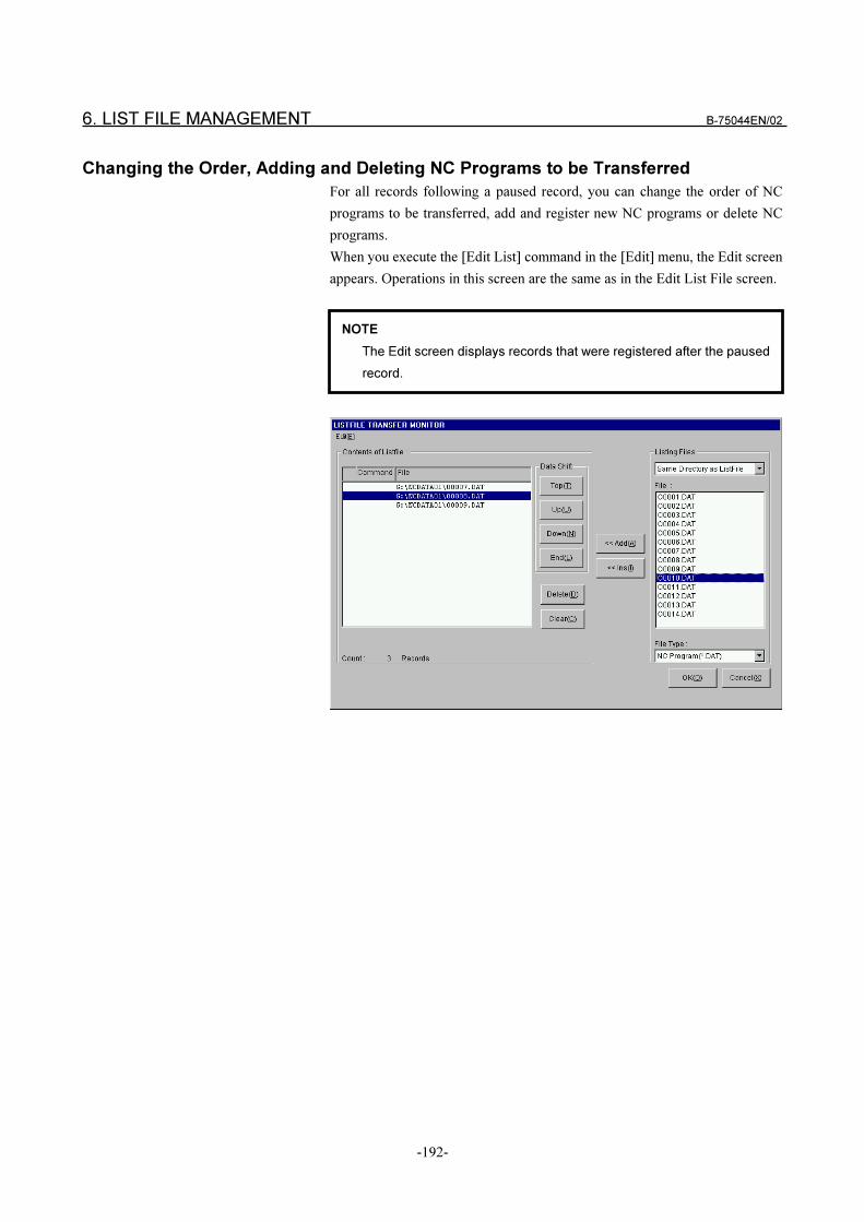
6. LIST FILE MANAGEMENT B-75044EN/02
-192-
Changing the Order, Adding and Deleting NC Programs to be Transferred
For all records following a paused record, you can change the order of NC
programs to be transferred, add and register new NC programs or delete NC
programs.
When you execute the [Edit List] command in the [Edit] menu, the Edit screen
appears. Operations in this screen are the same as in the Edit List File screen.
NOTE
The Edit screen displays records that were registered after the paused
record.

APPENDIX
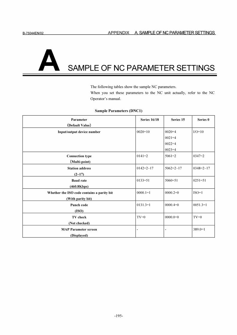
B-75044EN/02 APPENDIX A. SAMPLE OF NC PARAMETER SETTINGS
-195-
A SAMPLE OF NC PARAMETER SETTINGS
The following tables show the sample NC parameters.
When you set these parameters to the NC unit actually, refer to the NC
Operator’s manual.
Sample Parameters (DNC1)
Parameter
����Default Value����
Series 16/18 Series 15 Series 0
Input/output device number 0020=10 0020=4
0021=4
0022=4
0023=4
I/O=10
Connection type
����Multi-point)
0141=2 5061=2 0347=2
Station address
(2~17)
0142=2~17 5062=2~17 0348=2~17
Baud rate
(460.8Kbps)
0133=51 5060=51 0251=51
Whether the ISO code contains a parity bit
(With parity bit)
0000.1=1 0000.2=0 ISO=1
Punch code
(ISO)
0131.3=1 0000.4=0 0051.3=1
TV check
(Not checked)
TV=0 0000.0=0 TV=0
MAP Parameter screen
(Displayed)
- - 389.0=1
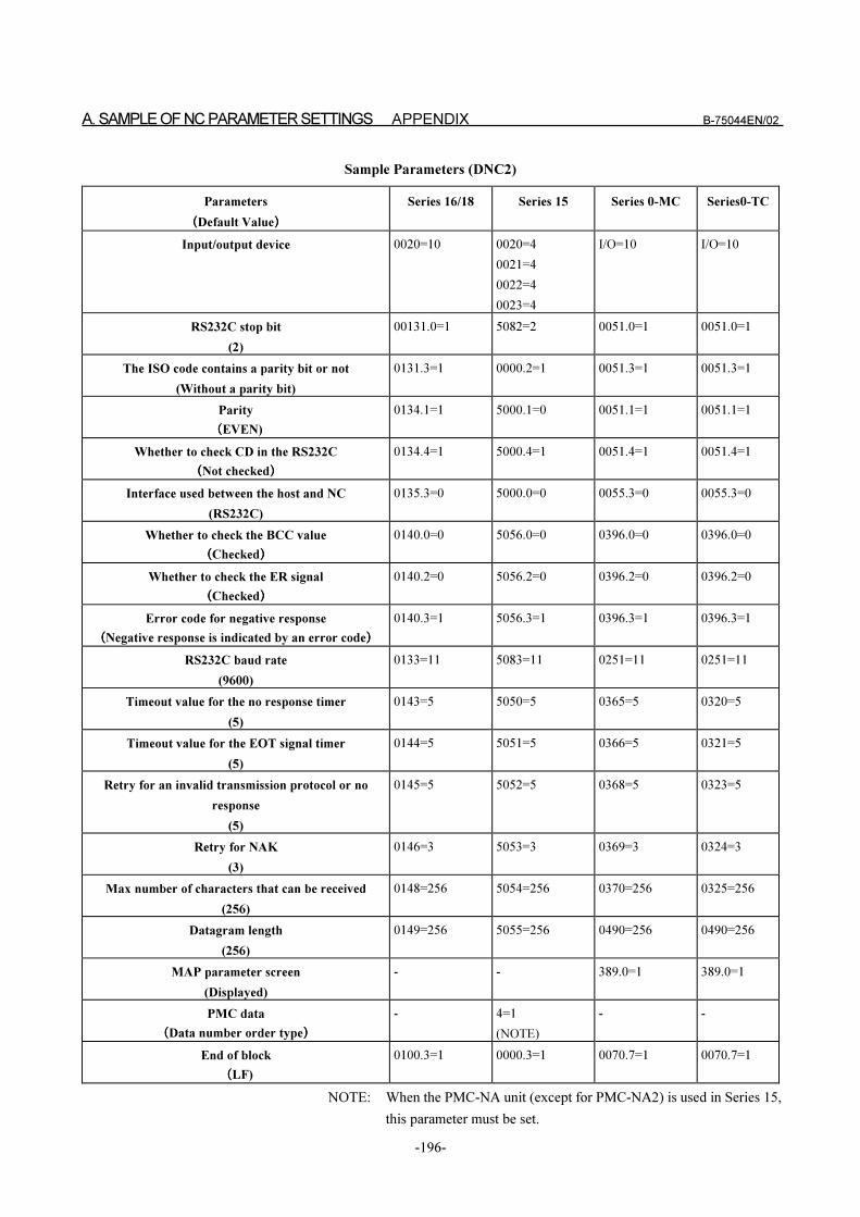
A. SAMPLE OF NC PARAMETER SETTINGS APPENDIX B-75044EN/02
-196-
Sample Parameters (DNC2)
Parameters
����Default Value����
Series 16/18 Series 15 Series 0-MC Series0-TC
Input/output device 0020=10 0020=4
0021=4
0022=4
0023=4
I/O=10 I/O=10
RS232C stop bit
(2)
00131.0=1 5082=2 0051.0=1 0051.0=1
The ISO code contains a parity bit or not
(Without a parity bit)
0131.3=1 0000.2=1 0051.3=1 0051.3=1
Parity
����EVEN)
0134.1=1 5000.1=0 0051.1=1 0051.1=1
Whether to check CD in the RS232C
����Not checked����
0134.4=1 5000.4=1 0051.4=1 0051.4=1
Interface used between the host and NC
(RS232C)
0135.3=0 5000.0=0 0055.3=0 0055.3=0
Whether to check the BCC value
����Checked����
0140.0=0 5056.0=0 0396.0=0 0396.0=0
Whether to check the ER signal
����Checked����
0140.2=0 5056.2=0 0396.2=0 0396.2=0
Error code for negative response
����Negative response is indicated by an error code����
0140.3=1 5056.3=1 0396.3=1 0396.3=1
RS232C baud rate
(9600)
0133=11 5083=11 0251=11 0251=11
Timeout value for the no response timer
(5)
0143=5 5050=5 0365=5 0320=5
Timeout value for the EOT signal timer
(5)
0144=5 5051=5 0366=5 0321=5
Retry for an invalid transmission protocol or no
response
(5)
0145=5 5052=5 0368=5 0323=5
Retry for NAK
(3)
0146=3 5053=3 0369=3 0324=3
Max number of characters that can be received
(256)
0148=256 5054=256 0370=256 0325=256
Datagram length
(256)
0149=256 5055=256 0490=256 0490=256
MAP parameter screen
(Displayed)
- - 389.0=1 389.0=1
PMC data
����Data number order type����
- 4=1
(NOTE)
- -
End of block
����LF)
0100.3=1 0000.3=1 0070.7=1 0070.7=1
NOTE: When the PMC-NA unit (except for PMC-NA2) is used in Series 15,
this parameter must be set.
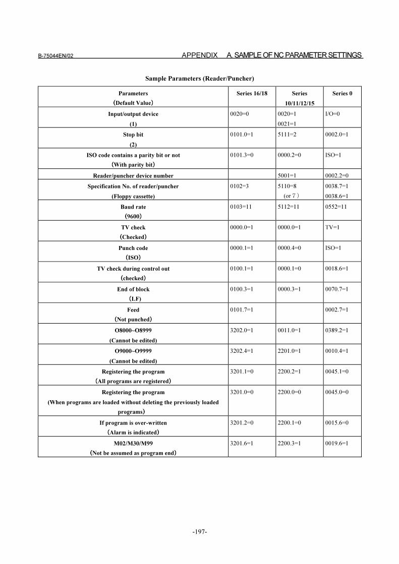
B-75044EN/02 APPENDIX A. SAMPLE OF NC PARAMETER SETTINGS
-197-
Sample Parameters (Reader/Puncher)
Parameters
����Default Value����
Series 16/18 Series
10/11/12/15
Series 0
Input/output device
(1)
0020=0 0020=1
0021=1
I/O=0
Stop bit
(2)
0101.0=1 5111=2 0002.0=1
ISO code contains a parity bit or not
����With parity bit����
0101.3=0 0000.2=0 ISO=1
Reader/puncher device number 5001=1 0002.2=0
Specification No. of reader/puncher
(Floppy cassette)
0102=3 5110=8
(or��
0038.7=1
0038.6=1
Baud rate
����9600����
0103=11 5112=11 0552=11
TV check
����Checked����
0000.0=1 0000.0=1 TV=1
Punch code
����ISO����
0000.1=1 0000.4=0 ISO=1
TV check during control out
����checked����
0100.1=1 0000.1=0 0018.6=1
End of block
����LF)
0100.3=1 0000.3=1 0070.7=1
Feed
����Not punched����
0101.7=1 0002.7=1
O8000~O8999
(Cannot be edited)
3202.0=1 0011.0=1 0389.2=1
O9000~O9999
(Cannot be edited)
3202.4=1 2201.0=1 0010.4=1
Registering the program
����All programs are registered����
3201.1=0 2200.2=1 0045.1=0
Registering the program
(When programs are loaded without deleting the previously loaded
programs����
3201.0=0 2200.0=0 0045.0=0
If program is over-written
����Alarm is indicated����
3201.2=0 2200.1=0 0015.6=0
M02/M30/M99
����Not be assumed as program end����
3201.6=1 2200.3=1 0019.6=1
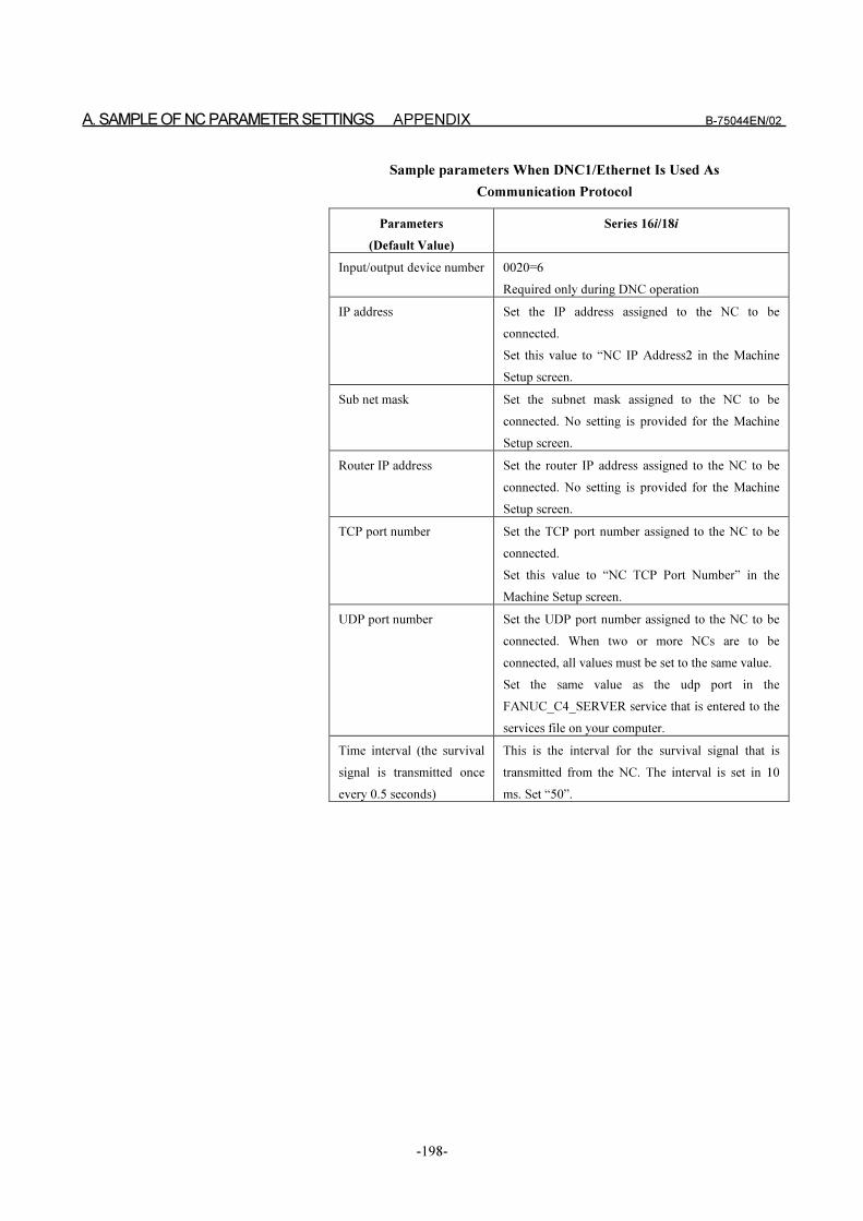
A. SAMPLE OF NC PARAMETER SETTINGS APPENDIX B-75044EN/02
-198-
Sample parameters When DNC1/Ethernet Is Used As
Communication Protocol
Parameters
(Default Value)
Series 16i/18i
Input/output device number 0020=6
Required only during DNC operation
IP address Set the IP address assigned to the NC to be
connected.
Set this value to “NC IP Address2 in the Machine
Setup screen.
Sub net mask Set the subnet mask assigned to the NC to be
connected. No setting is provided for the Machine
Setup screen.
Router IP address Set the router IP address assigned to the NC to be
connected. No setting is provided for the Machine
Setup screen.
TCP port number Set the TCP port number assigned to the NC to be
connected.
Set this value to “NC TCP Port Number” in the
Machine Setup screen.
UDP port number Set the UDP port number assigned to the NC to be
connected. When two or more NCs are to be
connected, all values must be set to the same value.
Set the same value as the udp port in the
FANUC_C4_SERVER service that is entered to the
services file on your computer.
Time interval (the survival
signal is transmitted once
every 0.5 seconds)
This is the interval for the survival signal that is
transmitted from the NC. The interval is set in 10
ms. Set “50”.

B-75044EN/02 APPENDIX B. SAMPLE OPERATION FOR NC
-199-
B SAMPLE OPERATION FOR NC
The following shows the sample operations of NC.
When you operate an NC unit, refer to the NC Operator’s manual.
B. SAMPLE OPERATION FOR NC APPENDIX B-75044EN/02
-200-
B.1 DNC1, DNC2
Sample operations for FS16/18
Procedure for Downloading an NC Program (NC Program Number)
The NC program to be downloaded is selected by “NC Program Number”.
1 Change the NC mode to “Edit”.
2 Push the <PROG> function key.
3 Push the [OPRT] soft key.
4 Push the [+] soft key.
5 Push the [READ] soft key.
6 Input the “O????”. Where, the “????” indicates the NC program
number you want to read.
7 Push the [EXEC] soft key.
Procedure for Uploading an NC Program (NC Program Number)
The uploaded NC program is saved by using “NC Program Number”.
1 Change the NC mode to “Edit”.
2 Push the <PROG> function key.
3 Push the [OPRT] soft key.
4 Push the [+] soft key.
5 Push the [PUNCH] soft key.
6 Input “O????”. Where, the “????” indicates the NC program number
you want to punch. It is also used for saving the uploaded program.
7 Push the [EXEC] soft key.
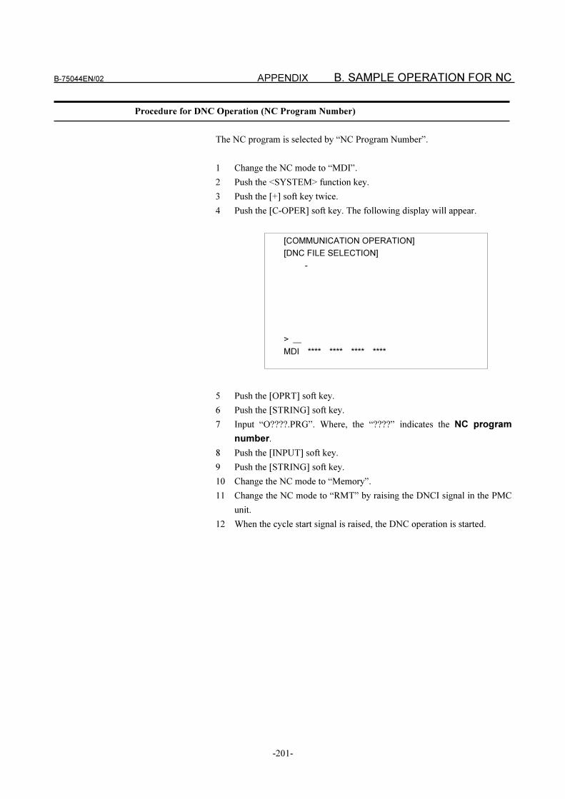
B-75044EN/02 APPENDIX B. SAMPLE OPERATION FOR NC
-201-
Procedure for DNC Operation (NC Program Number)
The NC program is selected by “NC Program Number”.
1 Change the NC mode to “MDI”.
2 Push the <SYSTEM> function key.
3 Push the [+] soft key twice.
4 Push the [C-OPER] soft key. The following display will appear.
5 Push the [OPRT] soft key.
6 Push the [STRING] soft key.
7 Input “O????.PRG”. Where, the “????” indicates the NC program
number.
8 Push the [INPUT] soft key.
9 Push the [STRING] soft key.
10 Change the NC mode to “Memory”.
11 Change the NC mode to “RMT” by raising the DNCI signal in the PMC
unit.
12 When the cycle start signal is raised, the DNC operation is started.
[COMMUNICATION OPERATION]
[DNC FILE SELECTION]
-
>
MDI **** **** **** ****
B. SAMPLE OPERATION FOR NC APPENDIX B-75044EN/02
-202-
Sample Operations for FS15
Procedure for Downloading an NC Program (NC Program Number)
The NC program to be downloaded is selected by “NC Program Number”.
1 Change the NC mode to “Edit”.
2 To select the PROGRAM(MEMORY) display, push the [PROGRAM]
soft key.
3 Push the�������������� soft key twice.
4 Push the [READ] soft key.
5 Input “,O????”. Where, the “????” indicates the NC program number
you want to read. A “,” character can be inputted by pushing both the “#”
key and the shift key.
6 Push the [EXEC] soft key.
Procedure for Uploading an NC Program (NC Program Number)
The uploaded NC program is saved by using “NC Program Number”.
1 Change the NC mode to “Edit”.
2 To select the PROGRAM(MEMORY) display, push the [PROGRAM]
soft key.
3 Push the [�������� ] soft key twice.
4 Push the [PUNCH] soft key.
5 Input “,O????”. Where, the “????” indicates the NC program number
you want to punch. It is also used for saving the uploaded program. A
“,” character can be inputted by pushing both the “#” key and the shift
key.
6 Push the [EXEC] soft key.
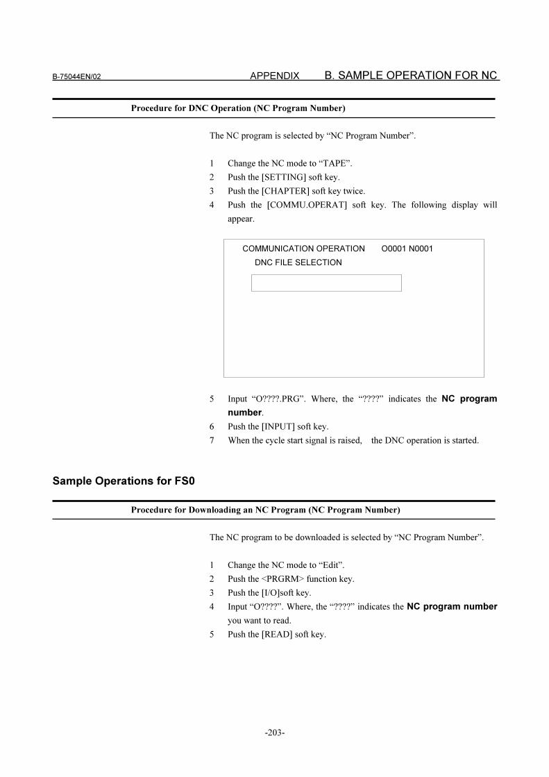
B-75044EN/02 APPENDIX B. SAMPLE OPERATION FOR NC
-203-
Procedure for DNC Operation (NC Program Number)
The NC program is selected by “NC Program Number”.
1 Change the NC mode to “TAPE”.
2 Push the [SETTING] soft key.
3 Push the [CHAPTER] soft key twice.
4 Push the [COMMU.OPERAT] soft key. The following display will
appear.
5 Input “O????.PRG”. Where, the “????” indicates the NC program
number.
6 Push the [INPUT] soft key.
7 When the cycle start signal is raised, the DNC operation is started.
Sample Operations for FS0
Procedure for Downloading an NC Program (NC Program Number)
The NC program to be downloaded is selected by “NC Program Number”.
1 Change the NC mode to “Edit”.
2 Push the <PRGRM> function key.
3 Push the [I/O]soft key.
4 Input “O????”. Where, the “????” indicates the NC program number
you want to read.
5 Push the [READ] soft key.
COMMUNICATION OPERATION O0001 N0001
DNC FILE SELECTION
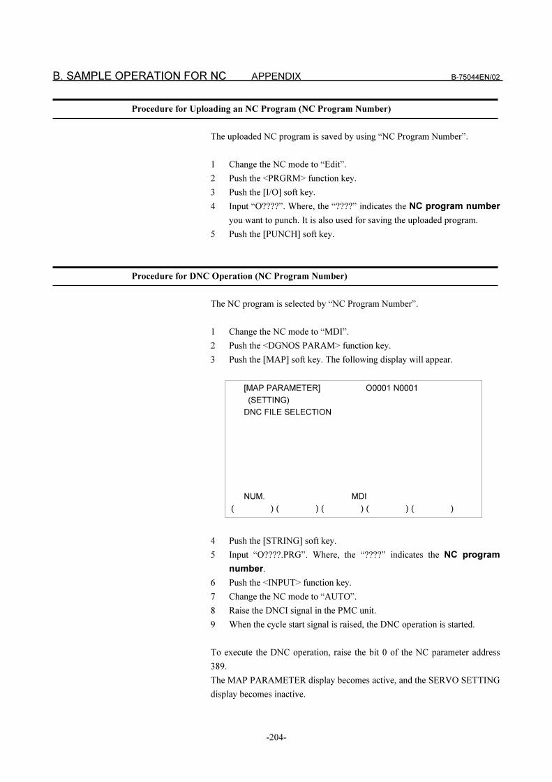
B. SAMPLE OPERATION FOR NC APPENDIX B-75044EN/02
-204-
Procedure for Uploading an NC Program (NC Program Number)
The uploaded NC program is saved by using “NC Program Number”.
1 Change the NC mode to “Edit”.
2 Push the <PRGRM> function key.
3 Push the [I/O] soft key.
4 Input “O????”. Where, the “????” indicates the NC program number
you want to punch. It is also used for saving the uploaded program.
5 Push the [PUNCH] soft key.
Procedure for DNC Operation (NC Program Number)
The NC program is selected by “NC Program Number”.
1 Change the NC mode to “MDI”.
2 Push the <DGNOS PARAM> function key.
3 Push the [MAP] soft key. The following display will appear.
4 Push the [STRING] soft key.
5 Input “O????.PRG”. Where, the “????” indicates the NC program
number.
6 Push the <INPUT> function key.
7 Change the NC mode to “AUTO”.
8 Raise the DNCI signal in the PMC unit.
9 When the cycle start signal is raised, the DNC operation is started.
To execute the DNC operation, raise the bit 0 of the NC parameter address
389.
The MAP PARAMETER display becomes active, and the SERVO SETTING
display becomes inactive.
[MAP PARAMETER] O0001 N0001
(SETTING)
DNC FILE SELECTION
NUM. MDI
( ) ( ) ( ) ( ) ( )
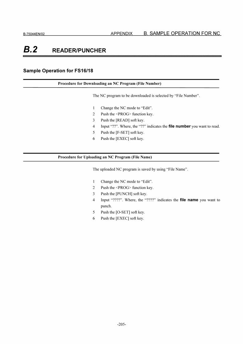
B-75044EN/02 APPENDIX B. SAMPLE OPERATION FOR NC
-205-
B.2 READER/PUNCHER
Sample Operation for FS16/18
Procedure for Downloading an NC Program (File Number)
The NC program to be downloaded is selected by “File Number”.
1 Change the NC mode to “Edit”.
2 Push the <PROG> function key.
3 Push the [READ] soft key.
4 Input “??”. Where, the “??” indicates the file number you want to read.
5 Push the [F-SET] soft key.
6 Push the [EXEC] soft key.
Procedure for Uploading an NC Program (File Name)
The uploaded NC program is saved by using “File Name”.
1 Change the NC mode to “Edit”.
2 Push the <PROG> function key.
3 Push the [PUNCH] soft key.
4 Input “????”. Where, the “????” indicates the file name you want to
punch.
5 Push the [O-SET] soft key.
6 Push the [EXEC] soft key.
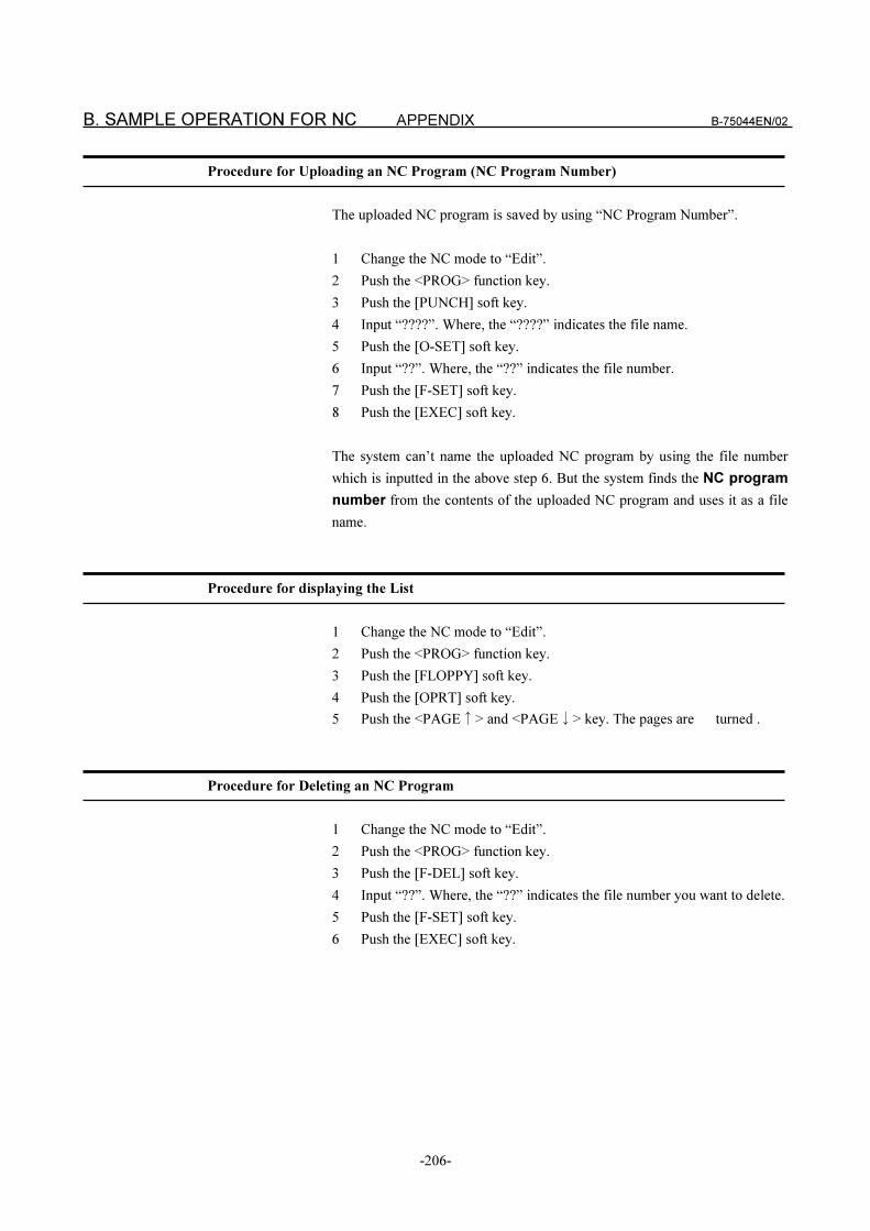
B. SAMPLE OPERATION FOR NC APPENDIX B-75044EN/02
-206-
Procedure for Uploading an NC Program (NC Program Number)
The uploaded NC program is saved by using “NC Program Number”.
1 Change the NC mode to “Edit”.
2 Push the <PROG> function key.
3 Push the [PUNCH] soft key.
4 Input “????”. Where, the “????” indicates the file name.
5 Push the [O-SET] soft key.
6 Input “??”. Where, the “??” indicates the file number.
7 Push the [F-SET] soft key.
8 Push the [EXEC] soft key.
The system can’t name the uploaded NC program by using the file number
which is inputted in the above step 6. But the system finds the NC program
number from the contents of the uploaded NC program and uses it as a file
name.
Procedure for displaying the List
1 Change the NC mode to “Edit”.
2 Push the <PROG> function key.
3 Push the [FLOPPY] soft key.
4 Push the [OPRT] soft key.
5 Push the <PAGE�> and <PAGE�> key. The pages are turned .
Procedure for Deleting an NC Program
1 Change the NC mode to “Edit”.
2 Push the <PROG> function key.
3 Push the [F-DEL] soft key.
4 Input “??”. Where, the “??” indicates the file number you want to delete.
5 Push the [F-SET] soft key.
6 Push the [EXEC] soft key.
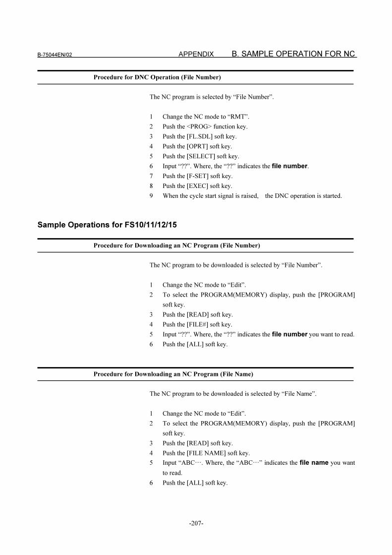
B-75044EN/02 APPENDIX B. SAMPLE OPERATION FOR NC
-207-
Procedure for DNC Operation (File Number)
The NC program is selected by “File Number”.
1 Change the NC mode to “RMT”.
2 Push the <PROG> function key.
3 Push the [FL.SDL] soft key.
4 Push the [OPRT] soft key.
5 Push the [SELECT] soft key.
6 Input “??”. Where, the “??” indicates the file number.
7 Push the [F-SET] soft key.
8 Push the [EXEC] soft key.
9 When the cycle start signal is raised, the DNC operation is started.
Sample Operations for FS10/11/12/15
Procedure for Downloading an NC Program (File Number)
The NC program to be downloaded is selected by “File Number”.
1 Change the NC mode to “Edit”.
2 To select the PROGRAM(MEMORY) display, push the [PROGRAM]
soft key.
3 Push the [READ] soft key.
4 Push the [FILE#] soft key.
5 Input “??”. Where, the “??” indicates the file number you want to read.
6 Push the [ALL] soft key.
Procedure for Downloading an NC Program (File Name)
The NC program to be downloaded is selected by “File Name”.
1 Change the NC mode to “Edit”.
2 To select the PROGRAM(MEMORY) display, push the [PROGRAM]
soft key.
3 Push the [READ] soft key.
4 Push the [FILE NAME] soft key.
5 Input “ABC�. Where, the “ABC�” indicates the file name you want
to read.
6 Push the [ALL] soft key.
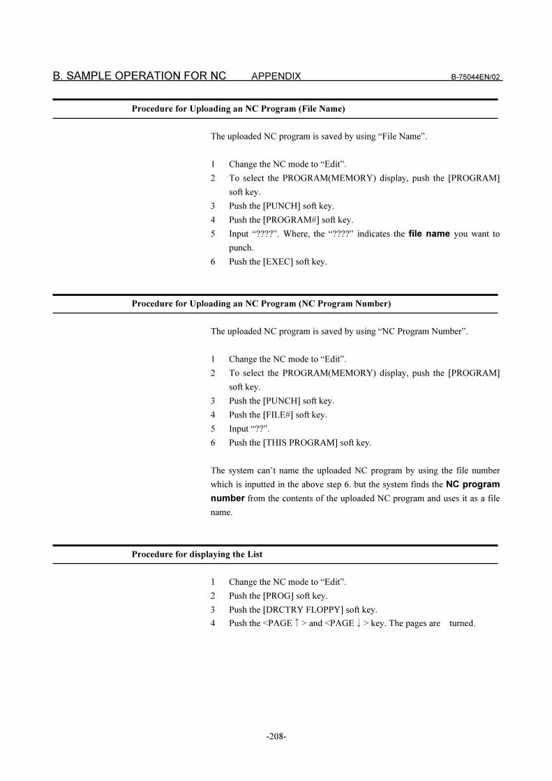
B. SAMPLE OPERATION FOR NC APPENDIX B-75044EN/02
-208-
Procedure for Uploading an NC Program (File Name)
The uploaded NC program is saved by using “File Name”.
1 Change the NC mode to “Edit”.
2 To select the PROGRAM(MEMORY) display, push the [PROGRAM]
soft key.
3 Push the [PUNCH] soft key.
4 Push the [PROGRAM#] soft key.
5 Input “????”. Where, the “????” indicates the file name you want to
punch.
6 Push the [EXEC] soft key.
Procedure for Uploading an NC Program (NC Program Number)
The uploaded NC program is saved by using “NC Program Number”.
1 Change the NC mode to “Edit”.
2 To select the PROGRAM(MEMORY) display, push the [PROGRAM]
soft key.
3 Push the [PUNCH] soft key.
4 Push the [FILE#] soft key.
5 Input “??”.
6 Push the [THIS PROGRAM] soft key.
The system can’t name the uploaded NC program by using the file number
which is inputted in the above step 6. but the system finds the NC program
number from the contents of the uploaded NC program and uses it as a file
name.
Procedure for displaying the List
1 Change the NC mode to “Edit”.
2 Push the [PROG] soft key.
3 Push the [DRCTRY FLOPPY] soft key.
4 Push the <PAGE�> and <PAGE�> key. The pages are turned.
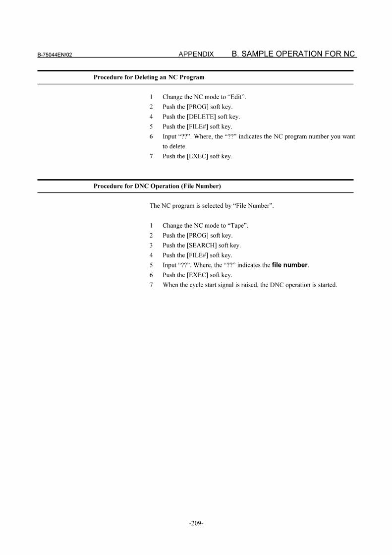
B-75044EN/02 APPENDIX B. SAMPLE OPERATION FOR NC
-209-
Procedure for Deleting an NC Program
1 Change the NC mode to “Edit”.
2 Push the [PROG] soft key.
4 Push the [DELETE] soft key.
5 Push the [FILE#] soft key.
6 Input “??”. Where, the “??” indicates the NC program number you want
to delete.
7 Push the [EXEC] soft key.
Procedure for DNC Operation (File Number)
The NC program is selected by “File Number”.
1 Change the NC mode to “Tape”.
2 Push the [PROG] soft key.
3 Push the [SEARCH] soft key.
4 Push the [FILE#] soft key.
5 Input “??”. Where, the “??” indicates the file number.
6 Push the [EXEC] soft key.
7 When the cycle start signal is raised, the DNC operation is started.
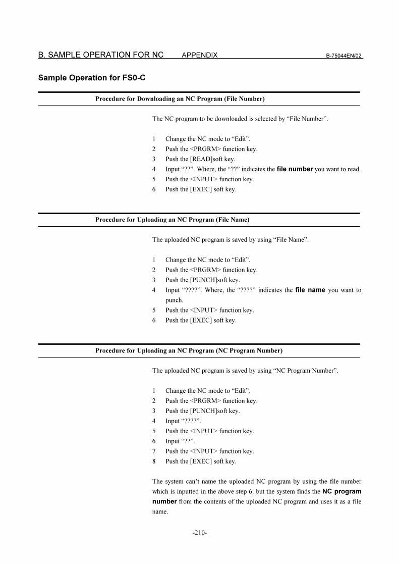
B. SAMPLE OPERATION FOR NC APPENDIX B-75044EN/02
-210-
Sample Operation for FS0-C
Procedure for Downloading an NC Program (File Number)
The NC program to be downloaded is selected by “File Number”.
1 Change the NC mode to “Edit”.
2 Push the <PRGRM> function key.
3 Push the [READ]soft key.
4 Input “??”. Where, the “??” indicates the file number you want to read.
5 Push the <INPUT> function key.
6 Push the [EXEC] soft key.
Procedure for Uploading an NC Program (File Name)
The uploaded NC program is saved by using “File Name”.
1 Change the NC mode to “Edit”.
2 Push the <PRGRM> function key.
3 Push the [PUNCH]soft key.
4 Input “????”. Where, the “????” indicates the file name you want to
punch.
5 Push the <INPUT> function key.
6 Push the [EXEC] soft key.
Procedure for Uploading an NC Program (NC Program Number)
The uploaded NC program is saved by using “NC Program Number”.
1 Change the NC mode to “Edit”.
2 Push the <PRGRM> function key.
3 Push the [PUNCH]soft key.
4 Input “????”.
5 Push the <INPUT> function key.
6 Input “??”.
7 Push the <INPUT> function key.
8 Push the [EXEC] soft key.
The system can’t name the uploaded NC program by using the file number
which is inputted in the above step 6. but the system finds the NC program
number from the contents of the uploaded NC program and uses it as a file
name.
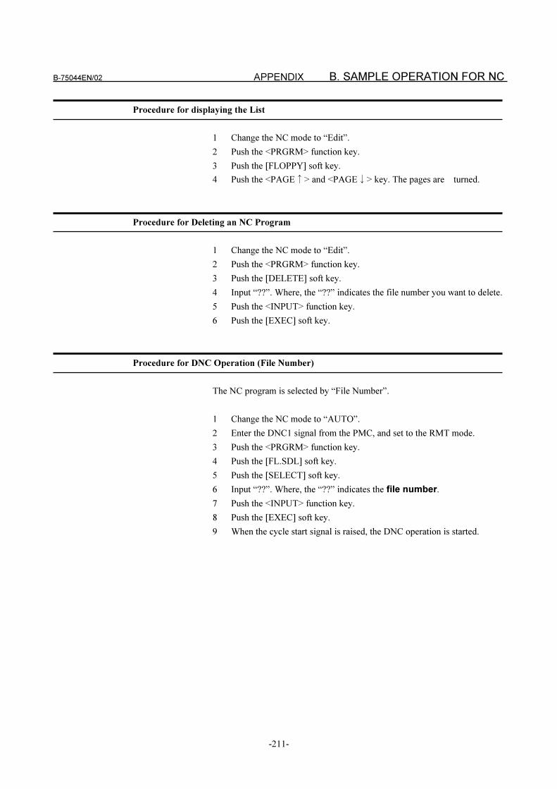
B-75044EN/02 APPENDIX B. SAMPLE OPERATION FOR NC
-211-
Procedure for displaying the List
1 Change the NC mode to “Edit”.
2 Push the <PRGRM> function key.
3 Push the [FLOPPY] soft key.
4 Push the <PAGE�> and <PAGE�> key. The pages are turned.
Procedure for Deleting an NC Program
1 Change the NC mode to “Edit”.
2 Push the <PRGRM> function key.
3 Push the [DELETE] soft key.
4 Input “??”. Where, the “??” indicates the file number you want to delete.
5 Push the <INPUT> function key.
6 Push the [EXEC] soft key.
Procedure for DNC Operation (File Number)
The NC program is selected by “File Number”.
1 Change the NC mode to “AUTO”.
2 Enter the DNC1 signal from the PMC, and set to the RMT mode.
3 Push the <PRGRM> function key.
4 Push the [FL.SDL] soft key.
5 Push the [SELECT] soft key.
6 Input “??”. Where, the “??” indicates the file number.
7 Push the <INPUT> function key.
8 Push the [EXEC] soft key.
9 When the cycle start signal is raised, the DNC operation is started.
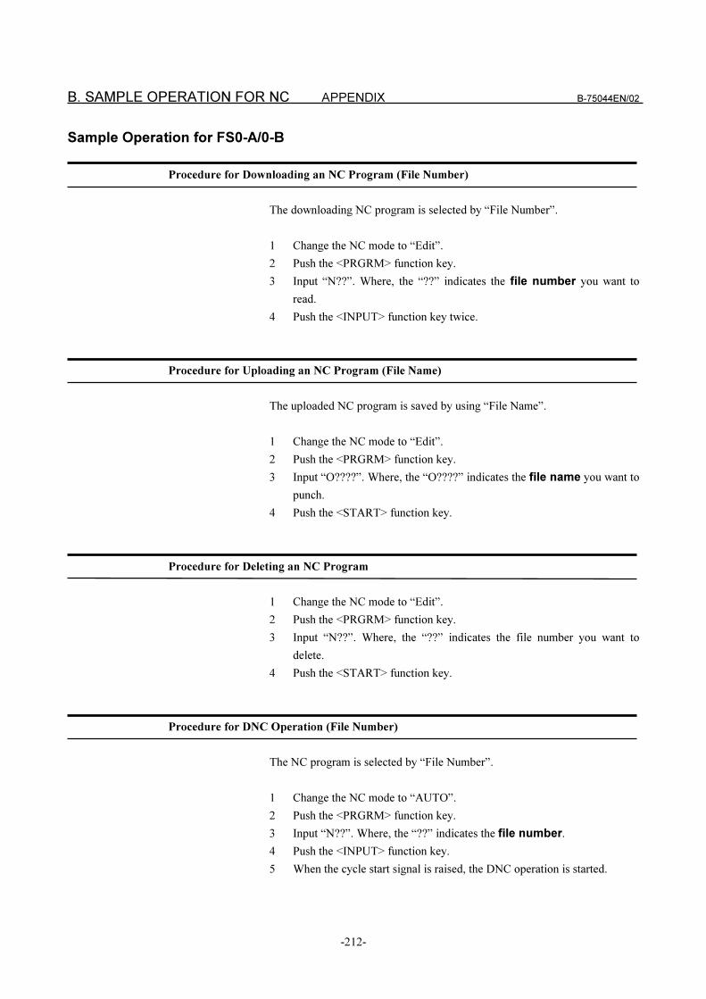
B. SAMPLE OPERATION FOR NC APPENDIX B-75044EN/02
-212-
Sample Operation for FS0-A/0-B
Procedure for Downloading an NC Program (File Number)
The downloading NC program is selected by “File Number”.
1 Change the NC mode to “Edit”.
2 Push the <PRGRM> function key.
3 Input “N??”. Where, the “??” indicates the file number you want to
read.
4 Push the <INPUT> function key twice.
Procedure for Uploading an NC Program (File Name)
The uploaded NC program is saved by using “File Name”.
1 Change the NC mode to “Edit”.
2 Push the <PRGRM> function key.
3 Input “O????”. Where, the “O????” indicates the file name you want to
punch.
4 Push the <START> function key.
Procedure for Deleting an NC Program
1 Change the NC mode to “Edit”.
2 Push the <PRGRM> function key.
3 Input “N??”. Where, the “??” indicates the file number you want to
delete.
4 Push the <START> function key.
Procedure for DNC Operation (File Number)
The NC program is selected by “File Number”.
1 Change the NC mode to “AUTO”.
2 Push the <PRGRM> function key.
3 Input “N??”. Where, the “??” indicates the file number.
4 Push the <INPUT> function key.
5 When the cycle start signal is raised, the DNC operation is started.
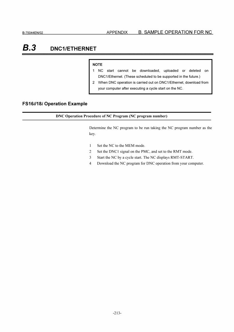
B-75044EN/02 APPENDIX B. SAMPLE OPERATION FOR NC
-213-
B.3 DNC1/ETHERNET
FS16i/18i Operation Example
DNC Operation Procedure of NC Program (NC program number)
Determine the NC program to be run taking the NC program number as the
key.
1 Set the NC to the MEM mode.
2 Set the DNC1 signal on the PMC, and set to the RMT mode.
3 Start the NC by a cycle start. The NC displays RMT-START.
4 Download the NC program for DNC operation from your computer.
NOTE
1 NC start cannot be downloaded, uploaded or deleted on
DNC1/Ethernet. (These scheduled to be supported in the future.)
2 When DNC operation is carried out on DNC1/Ethernet, download from
your computer after executing a cycle start on the NC.
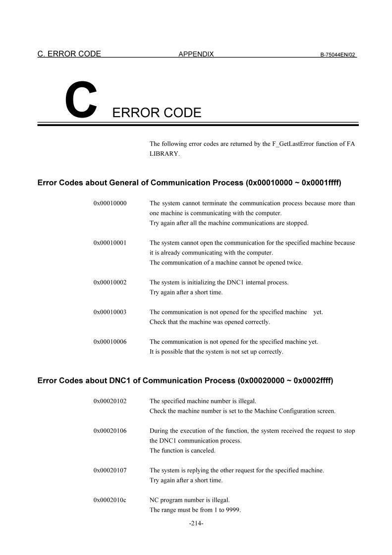
C. ERROR CODE APPENDIX B-75044EN/02
-214-
C ERROR CODE
The following error codes are returned by the F_GetLastError function of FA
LIBRARY.
Error Codes about General of Communication Process (0x00010000 ~ 0x0001ffff)
0x00010000 The system cannot terminate the communication process because more than
one machine is communicating with the computer.
Try again after all the machine communications are stopped.
0x00010001 The system cannot open the communication for the specified machine because
it is already communicating with the computer.
The communication of a machine cannot be opened twice.
0x00010002 The system is initializing the DNC1 internal process.
Try again after a short time.
0x00010003 The communication is not opened for the specified machine yet.
Check that the machine was opened correctly.
0x00010006 The communication is not opened for the specified machine yet.
It is possible that the system is not set up correctly.
Error Codes about DNC1 of Communication Process (0x00020000 ~ 0x0002ffff)
0x00020102 The specified machine number is illegal.
Check the machine number is set to the Machine Configuration screen.
0x00020106 During the execution of the function, the system received the request to stop
the DNC1 communication process.
The function is canceled.
0x00020107 The system is replying the other request for the specified machine.
Try again after a short time.
0x0002010c NC program number is illegal.
The range must be from 1 to 9999.
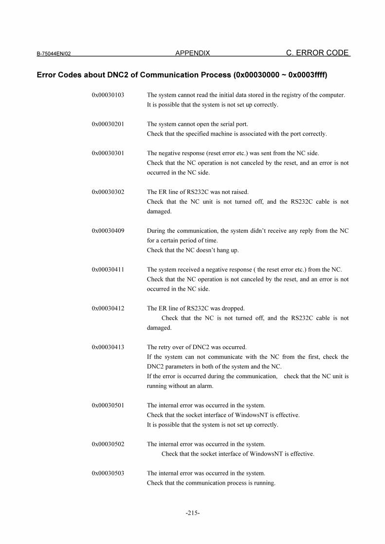
B-75044EN/02 APPENDIX C. ERROR CODE
-215-
Error Codes about DNC2 of Communication Process (0x00030000 ~ 0x0003ffff)
0x00030103 The system cannot read the initial data stored in the registry of the computer.
It is possible that the system is not set up correctly.
0x00030201 The system cannot open the serial port.
Check that the specified machine is associated with the port correctly.
0x00030301 The negative response (reset error etc.) was sent from the NC side.
Check that the NC operation is not canceled by the reset, and an error is not
occurred in the NC side.
0x00030302 The ER line of RS232C was not raised.
Check that the NC unit is not turned off, and the RS232C cable is not
damaged.
0x00030409 During the communication, the system didn’t receive any reply from the NC
for a certain period of time.
Check that the NC doesn’t hang up.
0x00030411 The system received a negative response ( the reset error etc.) from the NC.
Check that the NC operation is not canceled by the reset, and an error is not
occurred in the NC side.
0x00030412 The ER line of RS232C was dropped.
Check that the NC is not turned off, and the RS232C cable is not
damaged.
0x00030413 The retry over of DNC2 was occurred.
If the system can not communicate with the NC from the first, check the
DNC2 parameters in both of the system and the NC.
If the error is occurred during the communication, check that the NC unit is
running without an alarm.
0x00030501 The internal error was occurred in the system.
Check that the socket interface of WindowsNT is effective.
It is possible that the system is not set up correctly.
0x00030502 The internal error was occurred in the system.
Check that the socket interface of WindowsNT is effective.
0x00030503 The internal error was occurred in the system.
Check that the communication process is running.
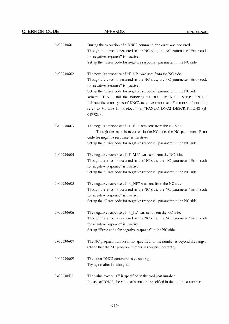
C. ERROR CODE APPENDIX B-75044EN/02
-216-
0x00030601 During the execution of a DNC2 command, the error was occurred.
Though the error is occurred in the NC side, the NC parameter “Error code
for negative response” is inactive.
Set up the “Error code for negative response” parameter in the NC side.
0x00030602 The negative response of “T_NP” was sent from the NC side.
Though the error is occurred in the NC side, the NC parameter “Error code
for negative response” is inactive.
Set up the “Error code for negative response” parameter in the NC side.
Where, “T_NP” and the following “T_BD”, “M_NR”, “N_NP”, “N_IL”
indicate the error types of DNC2 negative responses. For more information,
refer to Volume II “Protocol” in “FANUC DNC2 DESCRIPTIONS (B-
61992E)“.
0x00030603 The negative response of “T_BD” was sent from the NC side.
Though the error is occurred in the NC side, the NC parameter “Error
code for negative response” is inactive.
Set up the “Error code for negative response” parameter in the NC side.
0x00030604 The negative response of “T_MR” was sent from the NC side.
Though the error is occurred in the NC side, the NC parameter “Error code
for negative response” is inactive.
Set up the “Error code for negative response” parameter in the NC side.
0x00030605 The negative response of “N_NP” was sent from the NC side.
Though the error is occurred in the NC side, the NC parameter “Error code
for negative response” is inactive.
Set up the “Error code for negative response” parameter in the NC side.
0x00030606 The negative response of “N_IL” was sent from the NC side.
Though the error is occurred in the NC side, the NC parameter “Error code
for negative response” is inactive.
Set up “Error code for negative response” in the NC side.
0x00030607 The NC program number is not specified, or the number is beyond the range.
Check that the NC program number is specified correctly.
0x00030609 The other DNC2 command is executing.
Try again after finishing it.
0x00030f02 The value except “0” is specified in the tool post number.
In case of DNC2, the value of 0 must be specified in the tool post number.
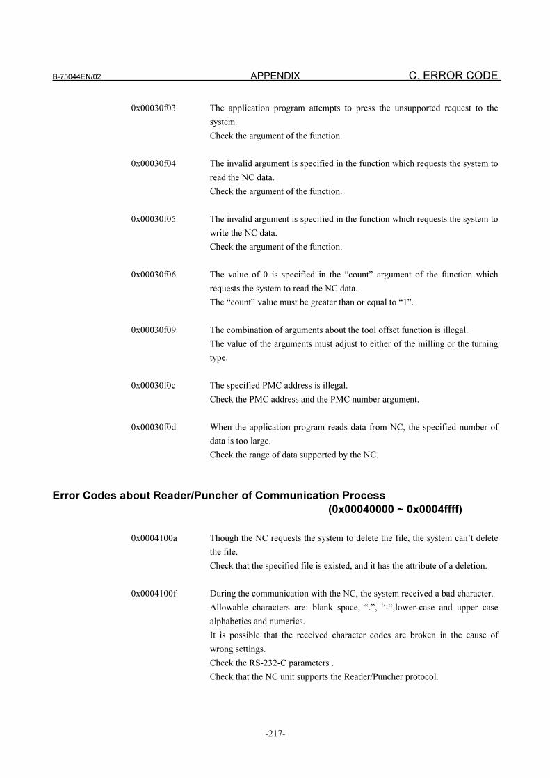
B-75044EN/02 APPENDIX C. ERROR CODE
-217-
0x00030f03 The application program attempts to press the unsupported request to the
system.
Check the argument of the function.
0x00030f04 The invalid argument is specified in the function which requests the system to
read the NC data.
Check the argument of the function.
0x00030f05 The invalid argument is specified in the function which requests the system to
write the NC data.
Check the argument of the function.
0x00030f06 The value of 0 is specified in the “count” argument of the function which
requests the system to read the NC data.
The “count” value must be greater than or equal to “1”.
0x00030f09 The combination of arguments about the tool offset function is illegal.
The value of the arguments must adjust to either of the milling or the turning
type.
0x00030f0c The specified PMC address is illegal.
Check the PMC address and the PMC number argument.
0x00030f0d When the application program reads data from NC, the specified number of
data is too large.
Check the range of data supported by the NC.
Error Codes about Reader/Puncher of Communication Process
(0x00040000 ~ 0x0004ffff)
0x0004100a Though the NC requests the system to delete the file, the system can’t delete
the file.
Check that the specified file is existed, and it has the attribute of a deletion.
0x0004100f During the communication with the NC, the system received a bad character.
Allowable characters are: blank space, “.”, “-“,lower-case and upper case
alphabetics and numerics.
It is possible that the received character codes are broken in the cause of
wrong settings.
Check the RS-232-C parameters .
Check that the NC unit supports the Reader/Puncher protocol.
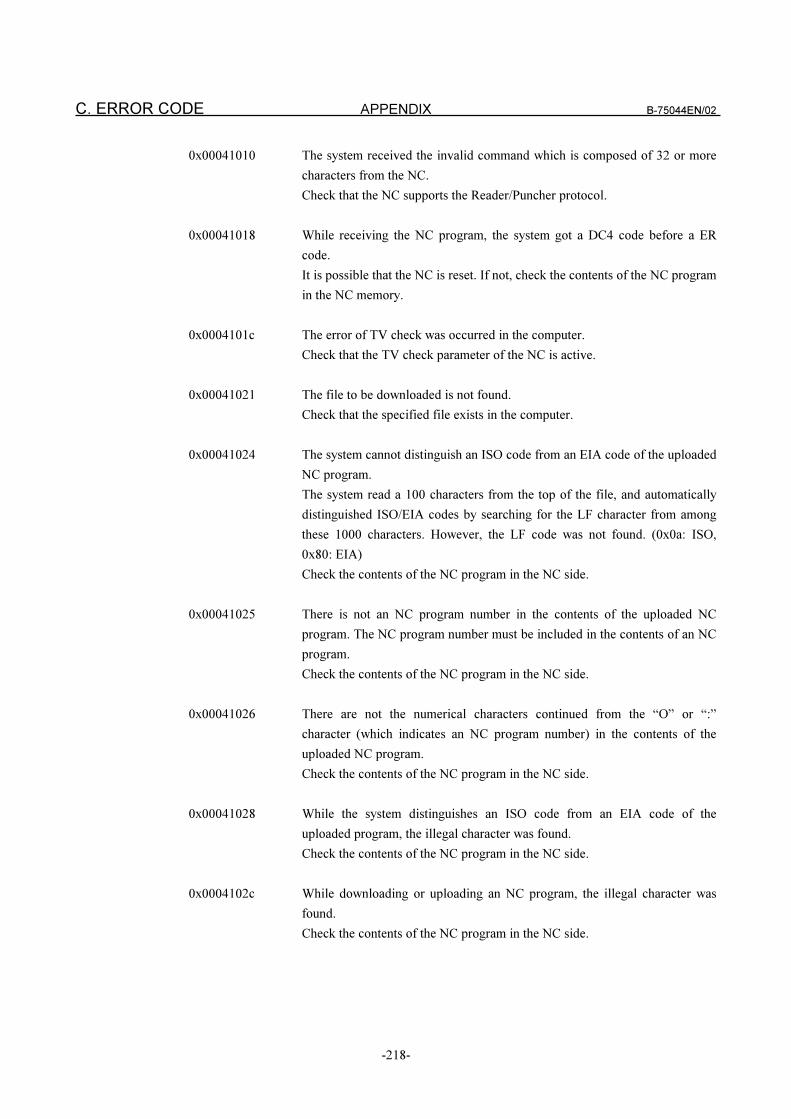
C. ERROR CODE APPENDIX B-75044EN/02
-218-
0x00041010 The system received the invalid command which is composed of 32 or more
characters from the NC.
Check that the NC supports the Reader/Puncher protocol.
0x00041018 While receiving the NC program, the system got a DC4 code before a ER
code.
It is possible that the NC is reset. If not, check the contents of the NC program
in the NC memory.
0x0004101c The error of TV check was occurred in the computer.
Check that the TV check parameter of the NC is active.
0x00041021 The file to be downloaded is not found.
Check that the specified file exists in the computer.
0x00041024 The system cannot distinguish an ISO code from an EIA code of the uploaded
NC program.
The system read a 100 characters from the top of the file, and automatically
distinguished ISO/EIA codes by searching for the LF character from among
these 1000 characters. However, the LF code was not found. (0x0a: ISO,
0x80: EIA)
Check the contents of the NC program in the NC side.
0x00041025 There is not an NC program number in the contents of the uploaded NC
program. The NC program number must be included in the contents of an NC
program.
Check the contents of the NC program in the NC side.
0x00041026 There are not the numerical characters continued from the “O” or “:”
character (which indicates an NC program number) in the contents of the
uploaded NC program.
Check the contents of the NC program in the NC side.
0x00041028 While the system distinguishes an ISO code from an EIA code of the
uploaded program, the illegal character was found.
Check the contents of the NC program in the NC side.
0x0004102c While downloading or uploading an NC program, the illegal character was
found.
Check the contents of the NC program in the NC side.
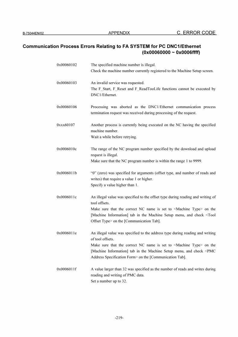
B-75044EN/02 APPENDIX C. ERROR CODE
-219-
Communication Process Errors Relating to FA SYSTEM for PC DNC1/Ethernet
(0x00060000 ~ 0x0006ffff)
0x00060102 The specified machine number is illegal.
Check the machine number currently registered to the Machine Setup screen.
0x00060103 An invalid service was requested.
The F_Start, F_Reset and F_ReadTooLife functions cannot be executed by
DNC1/Ethernet.
0x00060106 Processing was aborted as the DNC1/Ethernet communication process
termination request was received during processing of the request.
0xxx60107 Another process is currently being executed on the NC having the specified
machine number.
Wait a while before retrying.
0x0006010c The range of the NC program number specified by the download and upload
request is illegal.
Make sure that the NC program number is within the range 1 to 9999.
0x0006011b “0” (zero) was specified for arguments (offset type, and number of reads and
writes) that require a value 1 or higher.
Specify a value higher than 1.
0x0006011c An illegal value was specified to the offset type during reading and writing of
tool offsets.
Make sure that the correct NC name is set to <Machine Type> on the
[Machine Information] tab in the Machine Setup menu, and check <Tool
Offset Type> on the [Communication Tab].
0x0006011e An illegal value was specified to the address type during reading and writing
of tool offsets.
Make sure that the correct NC name is set to <Machine Type> on the
[Machine Information] tab in the Machine Setup menu, and check <PMC
Address Specification Form> on the [Communication Tab].
0x0006011f A value larger than 32 was specified as the number of reads and writes during
reading and writing of PMC data.
Set a number up to 32.
C. ERROR CODE APPENDIX B-75044EN/02
-220-
0x00060121 An error occurred during reading and writing of NC parameters.
Make sure that the correct NC name is set to <Machine Type> on the
[Machine Information] tab in the Machine Setup menu, and check <Bit Type
Data Type> on the [Communication Tab].
0x00060123 Cannot connect to the NC by Ethernet.
Check the “DNC1/Ethernet” setting in “2.6.3 Setups Relating to Machine
Communication” and the Ethernet cable connection.
0x00060125 An M198 call was received during DNC operation.
M198 calls are not accepted. Make sure that the program name is not
specified in “Select DNC File” in the NC's “Communication OP” screen.
0x00060126 An non-existent axis was specified during reading or writing of NC
parameters.
Check the maximum number of axes usable on the NC and the details of the
axis specification.
0x00060128 Cannot connect to the C4 server.
Check the “DNC1/Ethernet” setting in “2.6.3 Setups Relating to Machine
Communication” and the Ethernet cable connection.
0x0006012a The survival signal from the NC is interrupted.
Probable causes are that the NC was turned OFF, or that the Ethernet cable is
not connected. So, processing cannot be executed. Check the NC power
supply and Ethernet cable.
0x0006012c Download or upload started by the host was canceled by the cancel function.
0x0006012d Though canceling of download or upload started by the host was requested by
the host, the requested service is not currently being executed.
Check the machine number to be canceled and the cancel details.
0x0006012e The NC program that is requested for downloading and DNC program does
not contain an O number.
Check the contents of the NC program.
0x0006012f The parameter number specified during reading and writing of parameters
does not exist.
Check the parameter number.
0x000604f0 The NC was turned OFF during Ethernet communications. Or, the Ethernet
cable was cut.
Check the NC power supply and Ethernet cable.
B-75044EN/02 APPENDIX C. ERROR CODE
-221-
0x000604fe (1) A reset or emergency stop was executed on the NC during DNC operation by
start up from the computer.
Check the NC status and execute DNC operation again.
0x000604fe (2) A non-executable program was executed by DNC operation.
Check the program details.
0x000604ff (1) Programs cannot be deleted in the MDI mode.
Set to any mode other than the MDI mode.
0x000604ff (2) The currently selected program cannot be deleted in a mode other than the
EDT mode.
0x000604ff (3) A currently executing program cannot be selected.
0x00060503 (1) “0” was specified as the offset number during reading and writing of the tool
offset number. Or, a non-existent offset number on the NC was specified.
Check the offset number.
0x00060503 (2) A local variable or system variable, or non-existent macro number was
specified during writing to the custom macro variable.
Writing to local variables or system variables is not possible. Check the macro
number.
0x00060503 (3) A non-existent PMC data number was specified during reading and writing of
PMC data.
Check the PMC data Number.
0x00060503 (4) A value outside of the parameter range was specified during reading and
writing of NC parameters.
Check the write data.
0x00060504 (1) An illegal address was specified during reading and writing of PMC data.
Check the address.
0x00060504 (2) Writing to all areas of addresses F and X and writing to R9000 onwards was
specified.
Writing to these areas is not possible.
0x00060505 (1) When the 140 BP/S alarm occurred on the NC:
Downloading to the program currently selected on the NC is not possible.
0x00060505 (2) When the 73 BP/S alarm occurred on the NC:
Overwriting and downloading to an existing program is not possible. Check
NC parameter 3201#1.
0x00060505 (3) When the 72 BP/S alarm occurred on the NC:
The number of programs that can be registered to the NC has been exceeded.
Delete unwanted programs.
0x00060505 (4) Programs not existing in the NC cannot be uploaded.
0x00060505 (5) Programs not existing in the NC cannot be selected.
0x00060505 (6) Programs not existing in the NC cannot be deleted.
C. ERROR CODE APPENDIX B-75044EN/02
-222-
0x00060507 The NC program cannot be deleted as the memory protect key is ON.
Turn the memory protect key OFF.
0x00060508 When the 70 BP/S alarm occurred on the NC:
The “insufficient memory” error occurred on the NC during downloading.
Delete unwanted programs, and try downloading again.
0x0006050b The system number is wrongly specified.
Specify the correct system number.
0x0006050c Downloading in the MDI mode is not possible.
Change the mode to the EDT or MEM mode.
0x0006050d Though DNC operation started by the host was executed, the data transfer
request has not arrived from the NC.
Set the NC to the MEM mode, set the DNC1 signal to ON to set the NC to the
RMT mode, execute a cycle start and execute DNC operation started by the
host.
Other Errors Relating to FA SYSTEM for PC (0x10010000 ~ 0x1009ffff)
0x10010003 The computer ran out of memory during execution of FA SYSTEM for PC.
Either terminate unwanted applications, or increase the virtual memory to
secure more memory.
0x10011009 The computer ran out of memory during initialization of FA SYSTEM for PC.
Either terminate unwanted applications, or increase the virtual memory to
secure more memory.
0x10011102 The computer ran out of memory during initialization of FA SYSTEM for PC.
Either terminate unwanted applications, or increase the virtual memory to
secure more memory.
0x10011103 The computer ran out of memory during initialization of FA SYSTEM for PC.
Either terminate unwanted applications, or increase the virtual memory to
secure more memory.
0x10011106 Illegal machine number
Communication can be carried out only with machines that can be set in the
Machine Setup screen.
B-75044EN/02 APPENDIX C. ERROR CODE
-223-
0x10011107 Illegal file number
Make sure that a number 1 or larger is set to the file number.
A file having a number smaller than the specified file is registered to the
default directory. Check the file number.
0x10011108 Illegal file name
0x10011130 The default directory is not set in the Machine Setup screen.
Set the default directory.
0x10011131 Though downloading of the top file was carried out by Reader/Puncher
communication, the top file is not set.
Set the top file in the Select Transfer File screen.
0x10011132 Failed to delete a file.
Make sure that the file is not write-protected, or that it is not opened
exclusively by another process.
0x10013001 Failed to get the port number from the services file.
Make sure that the FANUC_PCFA_CDA entry is registered to the services
file.
0x10013101 Failed to get the port number from the services file.
Make sure that the FANUC_PFCA_CDA entry is registered to the services
file.
0x1002010a The file to download does not exist.
Make sure that the file to download exists.
0x1002010b The file to download cannot be opened.
Check the attributes of the file to download.
0x1002010c The file to download does not contain an O number.
Make sure that the file contains an O number.
0x1002010e An error occurred during reading of the file to download.
0x10020111 An error occurred during closing of the file to download.
0x10020112 An error occurred during moving of the file to overwrite by upload.
Check the attributes of the file to overwrite by upload.
0x10020113 An error occurred during creation of the file to upload.
Make sure that the directory settings are correct.
C. ERROR CODE APPENDIX B-75044EN/02
-224-
0x10020115 An error occurred during writing of the file to upload.
0x10020118 An error occurred during closing of the file to upload.
Make sure that the network is normal when the network directory is used.
0x10022011 Data whose MSB (8th bit) is 1 has been found.
Make sure that the NC program you are attempting to transfer does not
contain any illegal characters (Kanji characters, half-size kana characters,
etc.).
0x10022022 The O number of the file to download is more than 5 digits.
Keep the number of O number digits to 4 or less.
0x10022023 The O number of the file to download is “0” (zero).
Set the O number to a value other than “0”.
0x10022035 The buffer overflowed in a flush stop state.
Keep the capacity from the NC program end code up to the EOF or next O
number to within several tens of bytes.
0x10022052 The subprogram call nesting level has exceeded 8.
Limit the subprogram call nesting level to 8.
0x10022053 Failed to open the subprogram file.
Check the access rights of the subprogram file.
Make sure that the subprogram file is not in use by other processes.
0x10022054 The corresponding file for the subprogram call does not exist.
Make sure that the subprogram file call exists.
0x10022055 The next O number was found in the subprogram file.
Multi-volume files are not supported in subprogram files.
0x10022056 The subprogram file does not contain an M99 code.
Subprogram files need an M99 code.
0x10022058 The O number in the file does not match the subprogram file name.
The O number in the file must be the same as the subprogram file name.
0x10022059 An M02 or M30 codes was found in the subprogram file.
The M02 or M30 codes cannot be used in subprogram files.
B-75044EN/02 APPENDIX C. ERROR CODE
-225-
0x10022062 The M99 code was found in the main program for extended transfer of
subprogram files.
Main programs for extended transfer of subprogram files cannot contain an
M99 code.
0x10022091 Failed to open the transfer file.
Check the access rights of the transfer file.
Make sure that the transfer file is not in use by other processes.
0x10022092 The transfer file does not exist.
Make sure that the transfer file exists.
0x10022093 The transfer files in the separate transfer mode does not contain an O number.
The files specified in the list need an O number in the separate transfer mode.
(The O number in List Files is used only in extended transfer.)
0x100220a1 Line 1 of the NC program has exceeded 320 characters.
Limit lines including subprogram calls to 320 characters per line.
0x100220a2 The P code is “0” (zero).
Specify an O number (1 to 9999) valid for a P code.
0x100220a3 The P code is above 9999.
Specify an O number (1 to 9999) valid for a P code.
0x100220a4 Two P codes are set.
Do not specify two or more P codes in lines containing subprogram calls.
0x100220a5 Two L codes are set.
Do not specify two or more L codes in lines containing subprogram calls.
0x10022104 An attempt was made to re-transfer an O number that has already been
transfer.
Make sure that two or files having the same O number are not specified in the
list.
0x10022105 An MFC file exception occurred.
0x10022107 Failed to move the original file by overwrite upload.
Make sure that the original file is not in use by another process.
0x10022108 Failed to create the upload file.
Make sure that the directory in which the upload file is created exists.
Check the access rights of the directory in which the upload file is created.
C. ERROR CODE APPENDIX B-75044EN/02
-226-
0x1002210a Failed to write to the upload file.
0x1002210b Failed to close to the upload file.
0x1002210d An attempt was made to overwrite and upload a read-only file.
Make sure that the file has been correctly specified.
0x1003000b Failed to open the FA SYSTEM for PC setup data in the computer's registry.
Make sure that FA SYSTEM for PC is set up correctly.
Make sure that the Windows NT registry is not damaged.
0x1003000c Failed to read the FA SYSTEM for PC setup data in the computer's registry.
Make sure that FA SYSTEM for PC is set up correctly.
Make sure that the Windows NT registry is not damaged.
0x10040102 The value of the specified machine number is illegal.
0x10040105 The value of the specified descriptor is illegal.
Make sure that the value of the descriptor returned from FA LIBRARY is
used correctly, and that F_FreeID is not being executed on that descriptor.
0x10040106 The name of the specified computer is illegal.
0x1004010a The specified descriptor cannot be processed by this function.
The correspondence between the details indicated by the descriptor and the
function to be processed is in error such that the descriptor, that was handed
over when the tool offset was read, was handed over to the function for
copying the custom macro variable.
0x1004010b An attempt was made to copy the results data even though the data read
request failed.
0x1004010d The read start position specified by F_Seek() is a value larger than the number
of data items.
Make sure that the value of the read start position is within the range 0 to a
value smaller than the number of data items -1.
0x1004010f The file name and full path of the file is not set in a download or upload in
which the file name and full path of the file is specified.
0x10040110 The O number in an upload or download in which an O number is specified or
the O number specified by a selection or deletion is illegal.
Make sure that the O number is within the range 1 to 9999.
B-75044EN/02 APPENDIX C. ERROR CODE
-227-
0x10040111 Cannot find the execution format file for the communication process.
0x10040114 A machining center tool offset type is specified together with a lathe tool
offset type during reading and writing of the tool offset.
0x10040118 (1) “0” (zero) was specified as the number of data items during reading and
writing.
Set within the range 1 to 32.
0x10040118 (2) The tool offset type was not specified during reading and writing of the tool
offset.
Specify the tool offset type.
0x10040119 No valid notification message
0x1004011c The CDA Manager is not functioning.
When CDA Manager cannot function properly, check that
FANUC_PCFA_CDA is set to the services file.
A line feed is needed at the end of each line of data registered to the services
file.
0x1004011d No machines are set in the Machine Setup screen.
0x1004020f The Communication Manager is not functioning.
A probable cause is that F_Open was executed without executing
F_CreateCommunication, or that F_Close was executed after
F_TerminateCommunication was executed.
0x10040210 FANUC_PCFA_APP is not specified in the service file.
0x10060001 An attempt was made to open an already opened List File.
Close the file and try opening it again.
0x10060002 Failed to open the List File.
When an attempt is being made to manipulate the List File by machine, make
sure that the transfer is being carried out, and that the machine number is
correct.
When an attempt is being made to manipulate an existing original List File,
make sure that another process is not manipulating the same file, and that the
specified file name is correct.
When an attempt is being made to manipulate a new original List File, make
sure that the specified file is correct.
0x10060003 The specified List File does not exist.
Make sure that the specified List File does not contain any errors.
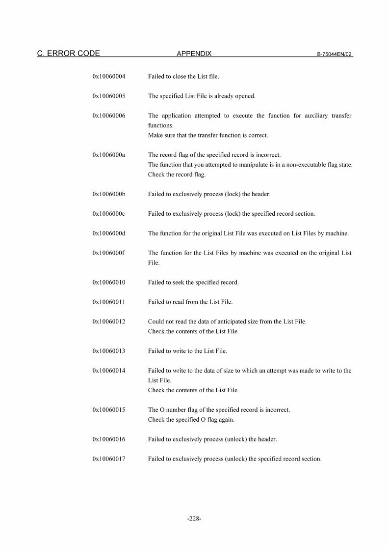
C. ERROR CODE APPENDIX B-75044EN/02
-228-
0x10060004 Failed to close the List file.
0x10060005 The specified List File is already opened.
0x10060006 The application attempted to execute the function for auxiliary transfer
functions.
Make sure that the transfer function is correct.
0x1006000a The record flag of the specified record is incorrect.
The function that you attempted to manipulate is in a non-executable flag state.
Check the record flag.
0x1006000b Failed to exclusively process (lock) the header.
0x1006000c Failed to exclusively process (lock) the specified record section.
0x1006000d The function for the original List File was executed on List Files by machine.
0x1006000f The function for the List Files by machine was executed on the original List
File.
0x10060010 Failed to seek the specified record.
0x10060011 Failed to read from the List File.
0x10060012 Could not read the data of anticipated size from the List File.
Check the contents of the List File.
0x10060013 Failed to write to the List File.
0x10060014 Failed to write to the data of size to which an attempt was made to write to the
List File.
Check the contents of the List File.
0x10060015 The O number flag of the specified record is incorrect.
Check the specified O flag again.
0x10060016 Failed to exclusively process (unlock) the header.
0x10060017 Failed to exclusively process (unlock) the specified record section.
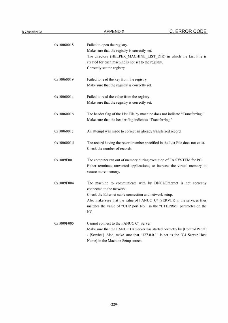
B-75044EN/02 APPENDIX C. ERROR CODE
-229-
0x10060018 Failed to open the registry.
Make sure that the registry is correctly set.
The directory (HELPER_MACHINE_LIST_DIR) in which the List File is
created for each machine is not set to the registry.
Correctly set the registry.
0x10060019 Failed to read the key from the registry.
Make sure that the registry is correctly set.
0x1006001a Failed to read the value from the registry.
Make sure that the registry is correctly set.
0x1006001b The header flag of the List File by machine does not indicate “Transferring.”
Make sure that the header flag indicates “Transferring.”
0x1006001c An attempt was made to correct an already transferred record.
0x1006001d The record having the record number specified in the List File does not exist.
Check the number of records.
0x1009F001 The computer ran out of memory during execution of FA SYSTEM for PC.
Either terminate unwanted applications, or increase the virtual memory to
secure more memory.
0x1009F004 The machine to communicate with by DNC1/Ethernet is not correctly
connected to the network.
Check the Ethernet cable connection and network setup.
Also make sure that the value of FANUC_C4_SERVER in the services files
matches the value of “UDP port No.” in the “ETHPRM” parameter on the
NC.
0x1009F005 Cannot connect to the FANUC C4 Server.
Make sure that the FANUC C4 Server has started correctly by [Control Panel]
- [Service]. Also, make sure that “127.0.0.1” is set as the [C4 Server Host
Name] in the Machine Setup screen.
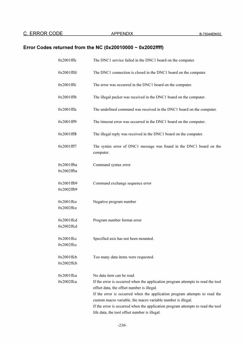
C. ERROR CODE APPENDIX B-75044EN/02
-230-
Error Codes returned from the NC (0x20010000 ~ 0x2002ffff)
0x2001fffe The DNC1 service failed in the DNC1 board on the computer.
0x2001fffd The DNC1 connection is closed in the DNC1 board on the computer.
0x2001fffc The error was occurred in the DNC1 board on the computer.
0x2001fffb The illegal packet was received in the DNC1 board on the computer.
0x2001fffa The undefined command was received in the DNC1 board on the computer.
0x2001fff9 The timeout error was occurred in the DNC1 board on the computer.
0x2001fff8 The illegal reply was received in the DNC1 board on the computer.
0x2001fff7 The syntax error of DNC1 message was found in the DNC1 board on the
computer.
0x2001ffba Command syntax error
0x2002ffba
0x2001ffb9 Command exchange sequence error
0x2002ffb9
0x2001ffce Negative program number
0x2002ffce
0x2001ffcd Program number format error
0x2002ffcd
0x2001ffcc Specified axis has not been mounted.
0x2002ffcc
0x2001ffcb Too many data items were requested.
0x2002ffcb
0x2001ffca No data item can be read.
0x2002ffca If the error is occurred when the application program attempts to read the tool
offset data, the offset number is illegal.
If the error is occurred when the application program attempts to read the
custom macro variable, the macro variable number is illegal.
If the error is occurred when the application program attempts to read the tool
life data, the tool offset number is illegal.
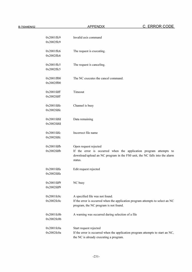
B-75044EN/02 APPENDIX C. ERROR CODE
-231-
0x2001ffc9 Invalid axis command
0x2002ffc9
0x2001ffc6 The request is executing.
0x2002ffc6
0x2001ffc5 The request is canceling.
0x2002ffc5
0x2001ff00 The NC executes the cancel command.
0x2002ff00
0x2001fdff Timeout
0x2002fdff
0x2001fdfe Channel is busy
0x2002fdfe
0x2001fdfd Data remaining
0x2002fdfd
0x2001fdfc Incorrect file name
0x2002fdfc
0x2001fdfb Open request rejected
0x2002fdfb If the error is occurred when the application program attempts to
download/upload an NC program in the FS0 unit, the NC falls into the alarm
status.
0x2001fdfa Edit request rejected
0x2002fdfa
0x2001fdf9 NC busy
0x2002fdf9
0x2001fc0c A specified file was not found.
0x2002fc0c If the error is occurred when the application program attempts to select an NC
program, the NC program is not found.
0x2001fc0b A warning was occurred during selection of a file
0x2002fc0b
0x2001fc0a Start request rejected
0x2002fc0a If the error is occurred when the application program attempts to start an NC,
the NC is already executing a program.
C. ERROR CODE APPENDIX B-75044EN/02
-232-
0x2001fc09 Not in auto mode
0x2002fc09 If the error is occurred when the application program attempts to start an NC,
the NC is not in the auto mode.
If the error is occurred when the application program attempts to select an NC
program, an NC is not the incorrect mode.
0x2001fc08 File selection request rejected
0x2002fc08 An NC program is being edited or executed in the NC. In case of FS0, the NC
falls in the alarm.
0x2001fc07 File deletion request rejected
0x2002fc07
0x2001fc06 File protected
0x2002fc06
0x2001fc05 File deletion request rejected, or warning occurred during
0x2002fc05 file deletion.
0x2001fc04 editing request rejected
0x2002fc04
0x2001fc03 Directory not found
0x2002fc03
0x2001fc02 Directory read request rejected
0x2002fc02
0x2001fc01 Invalid directory or file name
0x2002fc01
0x2001fba8 Window library error
0x2002fba8
0x2002fba7 Command not executable
0x2001fba7 If the error is occurred when the application program attempts to delete an NC
program in FS16/18, the specified NC program is being edited.
0x2002fba6 Invalid function code
0x2001fba6
0x2001fba5 Invalid big data classification
0x2002fba5 If the error is occurred when the application program attempts to read/write
the NC data, the data address is illegal.
0x2001fba4 Invalid medium data classification
0x2002fba4
B-75044EN/02 APPENDIX C. ERROR CODE
-233-
0x2001fba3 Invalid small data classification
0x2002fba3 If the error is occurred when the application program attempts to read/write
the NC data, the NC data address is illegal.
0x2001fba2 Invalid data length
0x2002fba2
0x2001fba1 Invalid data type
0x2002fba1
0x2001fba0 Invalid data
0x2002fba0
0x2001fb9f Miscellaneous command errors
0x2002fb9f
0x2001fb9e No option
0x2002fb9e If the error is occurred when the application program attempts to write the
custom macro variable, the NC doesn’t support the specified custom macro
variable number.
If the error is occurred when the application program attempts to write the
tool offset data, the NC doesn’t support the specified tool offset number.
0x2001fb9d File not found
0x2002fb9d If the error is occurred when an application program attempts to delete an NC
program, the specified NC program doesn’t exist in the NC memory.
0x2001fb9c File protected
0x2002fb9c
0x2001fb9b No directory space
0x2002fb9b
0x2001fb9a Insufficient memory space
0x2002fb9a
0x2001fb99 Read disable
0x2002fb99
0x2001fb98 Write disable
0x2002fb98 If the error is occurred when an application program attempts to delete an NC
program, the specified NC program is protected.
C. ERROR CODE APPENDIX B-75044EN/02
-234-
0x2001fb97 Write failed
0x2002fb97
0x2001fb96 Read failed
0x2002fb96
0x2001fb95 Device inoperable
0x2002fb95
0x2001fb94 System not ready
0x2002fb94
0x2001fb93 Invalid status
0x2002fb93 If the error is occurred when an application program attempts to delete an NC
program, the specified NC program is being edited.
0x2001fb92 Data mismatch
0x2002fb92
0x2001fb46 No extended window option
0x2002fb46
0x2001fb45 Miscellaneous errors
0x2002fb45
0x2001f62d Write protected
0x2002f62d If the error is occurred when an application program attempts to download an
NC program, the NC program numbers of the 8000s and 9000s are protected.
0x2001f625 Data not found
0x2002f625 If the error is occurred when an application program attempts to upload an NC
program, the specified NC program doesn’t exist in the NC memory.
0x2001f61f Program already exists.
0x2002f61f If the error is occurred when an application program attempts to download an
NC program, the NC prohibits the system from writing over an NC program.
0x2001f61e Insufficient program space
0x2002f61e If the error is occurred when an application program attempts to download an
NC program, there is no free space left on the NC memory .
0x2001f61b Too many programs
0x2002f61b
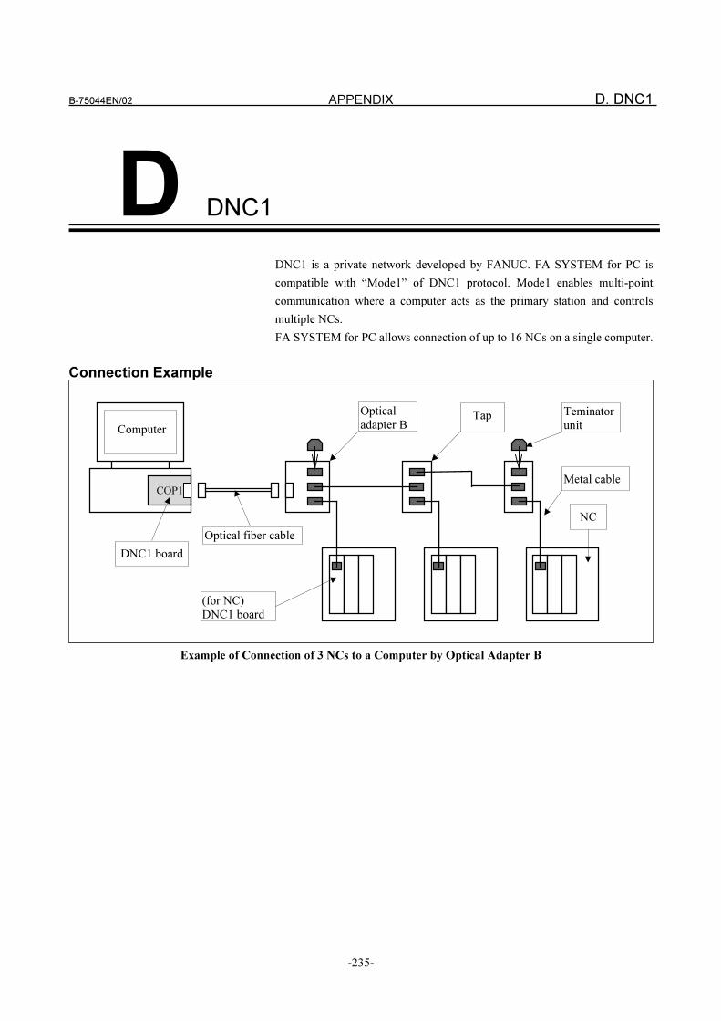
B-75044EN/02 APPENDIX D. DNC1
-235-
D DNC1
DNC1 is a private network developed by FANUC. FA SYSTEM for PC is
compatible with “Mode1” of DNC1 protocol. Mode1 enables multi-point
communication where a computer acts as the primary station and controls
multiple NCs.
FA SYSTEM for PC allows connection of up to 16 NCs on a single computer.
Connection Example
Example of Connection of 3 NCs to a Computer by Optical Adapter B
DNC1 board
(for NC)DNC1 board
NC
Optical fiber cable
COP1
Computer
Opticaladapter B
Teminatorunit
Tap
Metal cable
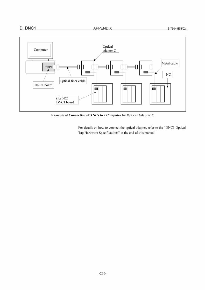
D. DNC1 APPENDIX B-75044EN/02
-236-
Example of Connection of 3 NCs to a Computer by Optical Adapter C
For details on how to connect the optical adapter, refer to the “DNC1 Optical
Tap Hardware Specifications” at the end of this manual.
Optical
adapter C
DNC1 board
(for NC)
DNC1 board
NC
Optical fiber cable
COP1
Computer
Metal cable
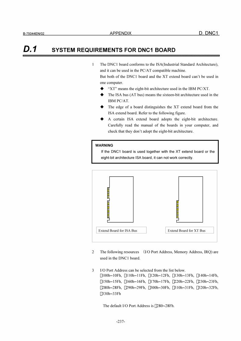
B-75044EN/02 APPENDIX D. DNC1
-237-
D.1 SYSTEM REQUIREMENTS FOR DNC1 BOARD
1 The DNC1 board conforms to the ISA(Industrial Standard Architecture),
and it can be used in the PC/AT compatible machine.
But both of the DNC1 board and the XT extend board can’t be used in
one computer.
� “XT” means the eight-bit architecture used in the IBM PC/XT.
� The ISA bus (AT bus) means the sixteen-bit architecture used in the
IBM PC/AT.
� The edge of a board distinguishes the XT extend board from the
ISA extend board. Refer to the following figure.
� A certain ISA extend board adopts the eight-bit architecture.
Carefully read the manual of the boards in your computer, and
check that they don’t adopt the eight-bit architecture.
Extend Board for XT Bus Extend Board for ISA Bus
2 The following resources �I/O Port Address, Memory Address, IRQ) are
used in the DNC1 board.
3 I/O Port Address can be selected from the list below.
� 100h~10Fh, � 110h~11Fh, � 120h~12Fh, � 130h~13Fh, � 140h~14Fh,
� 150h~15Fh, � 160h~16Fh, � 170h~17Fh, � 220h~22Fh, � 230h~23Fh,
� 280h~28Fh, � 290h~29Fh, � 300h~30Fh, � 310h~31Fh, � 320h~32Fh,
� 330h~33Fh
The default I/O Port Address is � 280~28Fh.
WARNING
If the DNC1 board is used together with the XT extend board or the
eight-bit architecture ISA board, it can not work correctly.

D. DNC1 APPENDIX B-75044EN/02
-238-
4 Memory Address can be selected from the list below.
� C0000h~C7FFFh, � C8000h~CFFFFh, � D0000h~D7FFFh,
� D8000h~DFFFFh, � E0000h~E7FFFh, � E8000h~EFFFFh
5 IRQ can be selected from the list below.
� 3, � 5, � 7, � 9, � 10, � 11, � 15
6 The DNC1 board spends the power supply like this.
+5V, 1.4A(maximum)

B-75044EN/02 APPENDIX D. DNC1
-239-
D.2 CONDITIONS FOR USING THE DNC1 DRIVER
The WinRT software is used in the DNC1 driver.
If WinRT is also used in other software packages of your computer, the
DNC1 driver can not be installed.
�� WinRT is the trademark of Blue Water Systems Co.
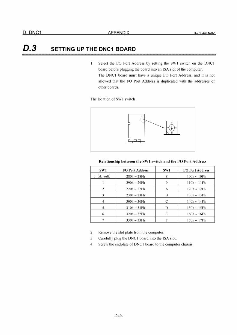
D. DNC1 APPENDIX B-75044EN/02
-240-
D.3 SETTING UP THE DNC1 BOARD
1 Select the I/O Port Address by setting the SW1 switch on the DNC1
board before plugging the board into an ISA slot of the computer.
The DNC1 board must have a unique I/O Port Address, and it is not
allowed that the I/O Port Address is duplicated with the addresses of
other boards.
The location of SW1 switch
8
4
C
0
Relationship between the SW1 switch and the I/O Port Address
SW1 I/O Port Address SW1 I/O Port Address
0�default� 280h ~ 28Fh 8 100h ~ 10Fh
1 290h ~ 29Fh 9 110h ~ 11Fh
2 220h ~ 22Fh A 120h ~ 12Fh
3 230h ~ 23Fh B 130h ~ 13Fh
4 300h ~ 30Fh C 140h ~ 14Fh
5 310h ~ 31Fh D 150h ~ 15Fh
6 320h ~ 32Fh E 160h ~ 16Fh
7 330h ~ 33Fh F 170h ~ 17Fh
2 Remove the slot plate from the computer.
3 Carefully plug the DNC1 board into the ISA slot.
4 Screw the endplate of DNC1 board to the computer chassis.
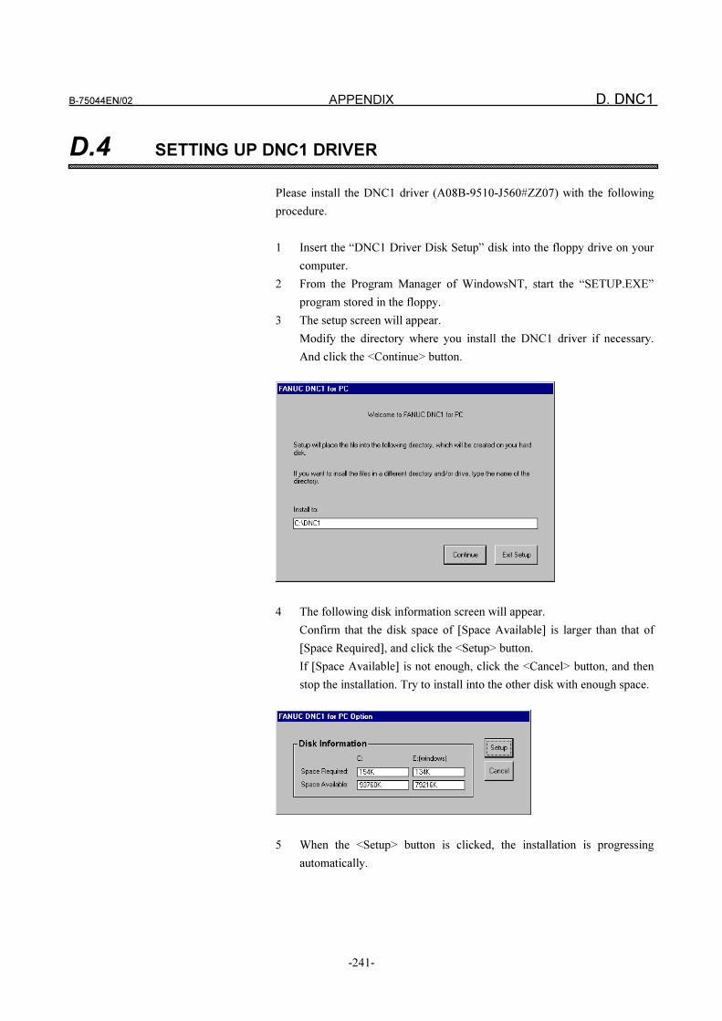
B-75044EN/02 APPENDIX D. DNC1
-241-
D.4 SETTING UP DNC1 DRIVER
Please install the DNC1 driver (A08B-9510-J560#ZZ07) with the following
procedure.
1 Insert the “DNC1 Driver Disk Setup” disk into the floppy drive on your
computer.
2 From the Program Manager of WindowsNT, start the “SETUP.EXE”
program stored in the floppy.
3 The setup screen will appear.
Modify the directory where you install the DNC1 driver if necessary.
And click the <Continue> button.
4 The following disk information screen will appear.
Confirm that the disk space of [Space Available] is larger than that of
[Space Required], and click the <Setup> button.
If [Space Available] is not enough, click the <Cancel> button, and then
stop the installation. Try to install into the other disk with enough space.
5 When the <Setup> button is clicked, the installation is progressing
automatically.
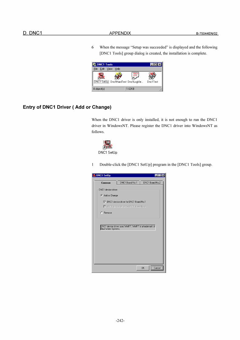
D. DNC1 APPENDIX B-75044EN/02
-242-
6 When the message “Setup was succeeded” is displayed and the following
[DNC1 Tools] group dialog is created, the installation is complete.
Entry of DNC1 Driver ( Add or Change)
When the DNC1 driver is only installed, it is not enough to run the DNC1
driver in WindowsNT. Please register the DNC1 driver into WindowsNT as
follows.
1 Double-click the [DNC1 SetUp] program in the [DNC1 Tools] group.
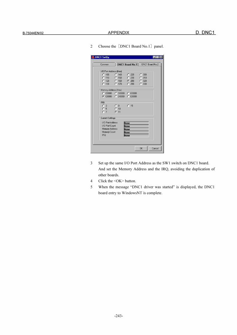
B-75044EN/02 APPENDIX D. DNC1
-243-
2 Choose the�DNC1 Board No.1�panel.
3 Set up the same I/O Port Address as the SW1 switch on DNC1 board.
And set the Memory Address and the IRQ, avoiding the duplication of
other boards.
4 Click the <OK> button.
5 When the message “DNC1 driver was started” is displayed, the DNC1
board entry to WindowsNT is complete.
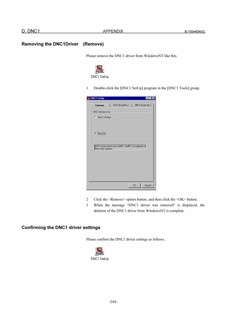
D. DNC1 APPENDIX B-75044EN/02
-244-
Removing the DNC1Driver (Remove)
Please remove the DNC1 driver from WindowsNT like this.
1 Double-click the [DNC1 SetUp] program in the [DNC1 Tools] group.
2 Click the <Remove> option button, and then click the <OK> button.
3 When the message “DNC1 driver was removed” is displayed, the
deletion of the DNC1 driver from WindowsNT is complete.
Confirming the DNC1 driver settings
Please confirm the DNC1 driver settings as follows.
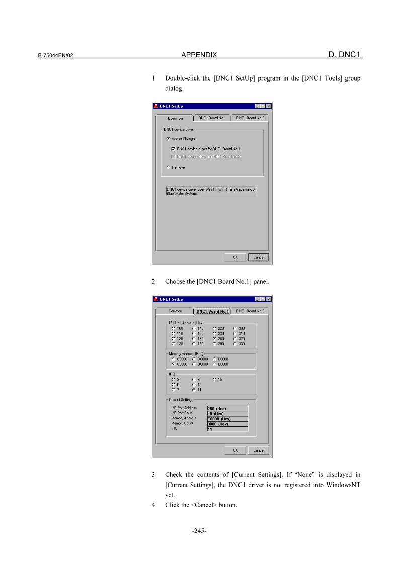
B-75044EN/02 APPENDIX D. DNC1
-245-
1 Double-click the [DNC1 SetUp] program in the [DNC1 Tools] group
dialog.
2 Choose the [DNC1 Board No.1] panel.
3 Check the contents of [Current Settings]. If “None” is displayed in
[Current Settings], the DNC1 driver is not registered into WindowsNT
yet.
4 Click the <Cancel> button.
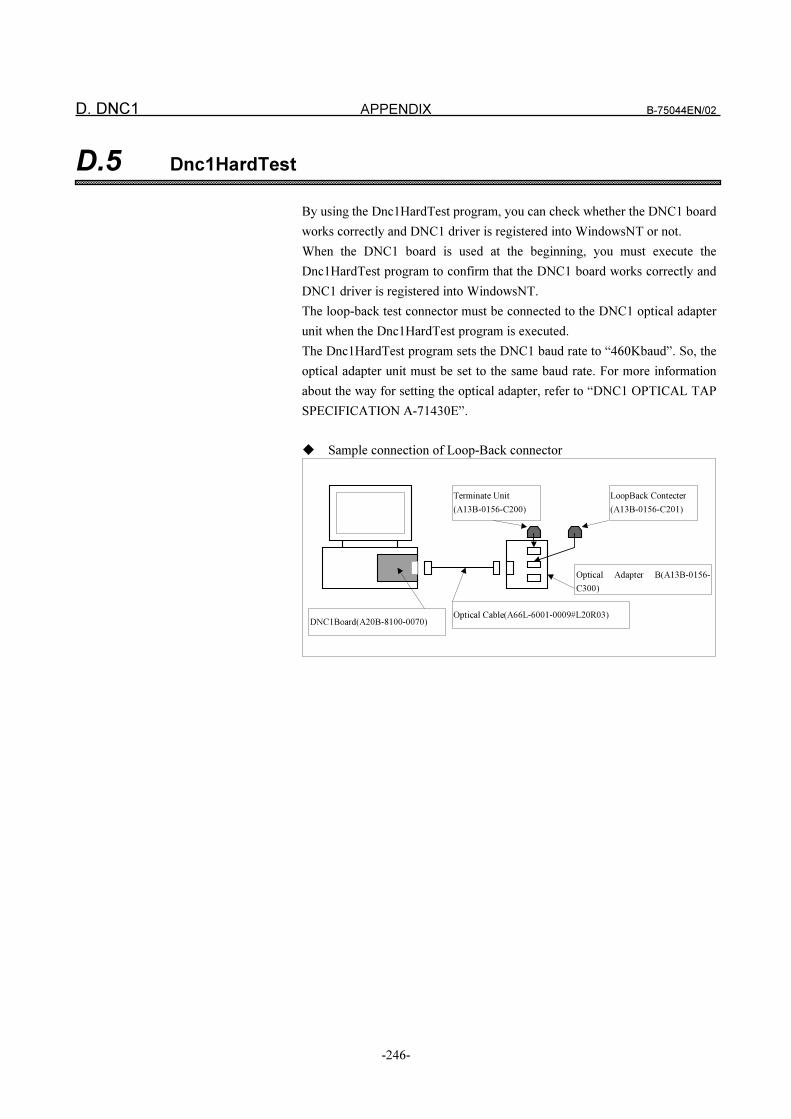
D. DNC1 APPENDIX B-75044EN/02
-246-
D.5 Dnc1HardTest
By using the Dnc1HardTest program, you can check whether the DNC1 board
works correctly and DNC1 driver is registered into WindowsNT or not.
When the DNC1 board is used at the beginning, you must execute the
Dnc1HardTest program to confirm that the DNC1 board works correctly and
DNC1 driver is registered into WindowsNT.
The loop-back test connector must be connected to the DNC1 optical adapter
unit when the Dnc1HardTest program is executed.
The Dnc1HardTest program sets the DNC1 baud rate to “460Kbaud”. So, the
optical adapter unit must be set to the same baud rate. For more information
about the way for setting the optical adapter, refer to “DNC1 OPTICAL TAP
SPECIFICATION A-71430E”.
� Sample connection of Loop-Back connector
LoopBack Contecter
(A13B-0156-C201)
Terminate Unit
(A13B-0156-C200)
Optical Adapter B(A13B-0156-
C300)
Optical Cable(A66L-6001-0009#L20R03)DNC1Board(A20B-8100-0070)
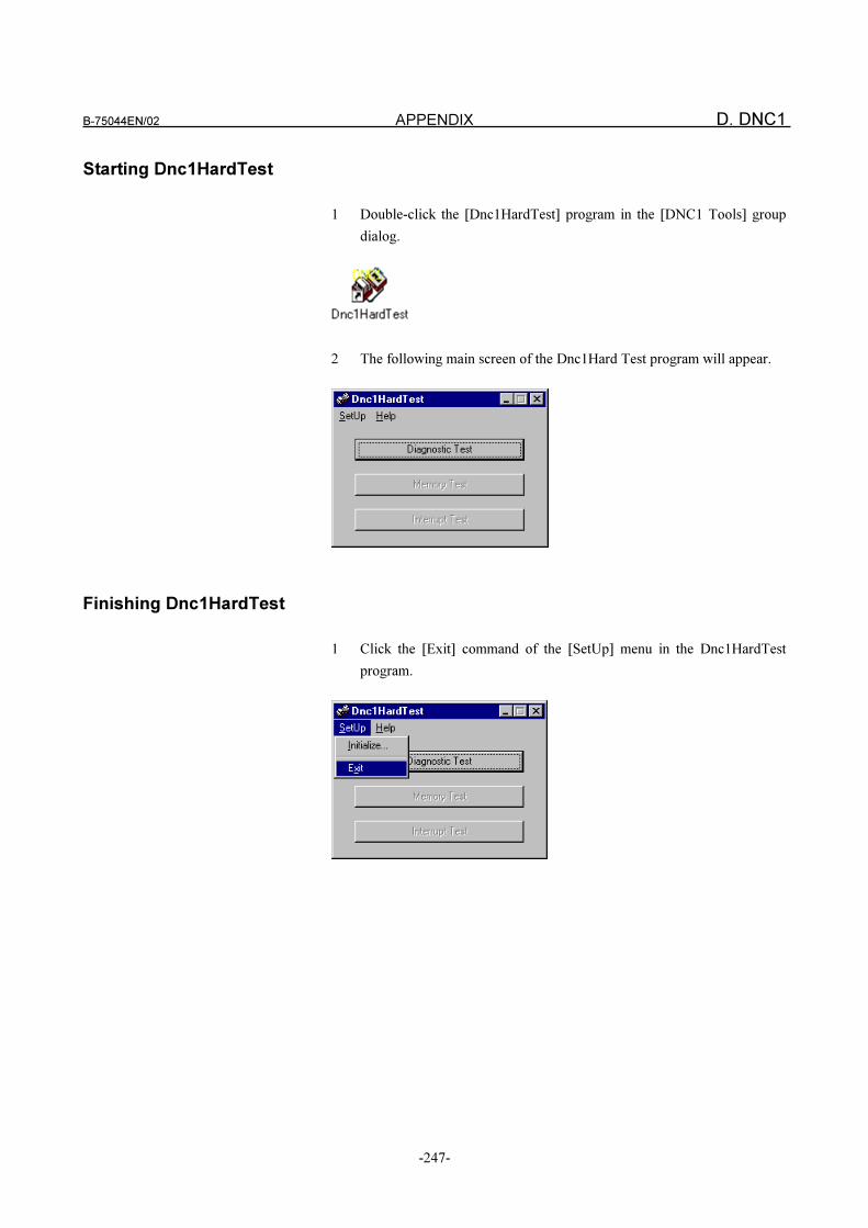
B-75044EN/02 APPENDIX D. DNC1
-247-
Starting Dnc1HardTest
1 Double-click the [Dnc1HardTest] program in the [DNC1 Tools] group
dialog.
2 The following main screen of the Dnc1Hard Test program will appear.
Finishing Dnc1HardTest
1 Click the [Exit] command of the [SetUp] menu in the Dnc1HardTest
program.
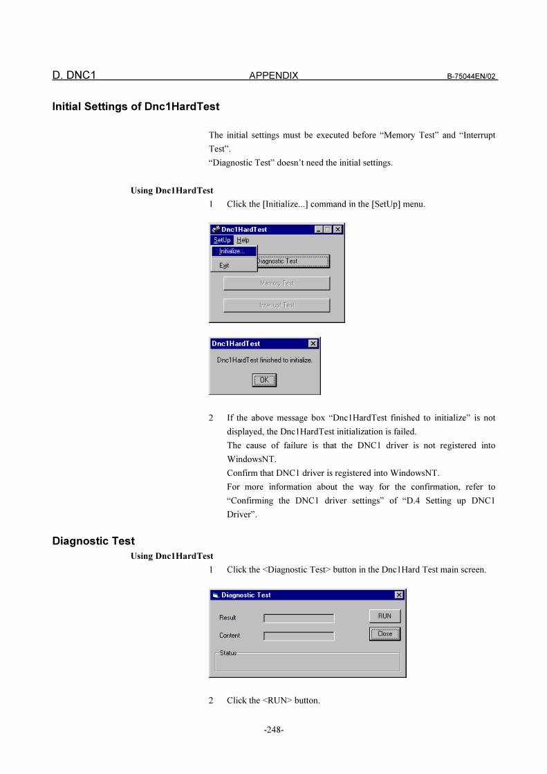
D. DNC1 APPENDIX B-75044EN/02
-248-
Initial Settings of Dnc1HardTest
The initial settings must be executed before “Memory Test” and “Interrupt
Test”.
“Diagnostic Test” doesn’t need the initial settings.
Using Dnc1HardTest
1 Click the [Initialize...] command in the [SetUp] menu.
2 If the above message box “Dnc1HardTest finished to initialize” is not
displayed, the Dnc1HardTest initialization is failed.
The cause of failure is that the DNC1 driver is not registered into
WindowsNT.
Confirm that DNC1 driver is registered into WindowsNT.
For more information about the way for the confirmation, refer to
“Confirming the DNC1 driver settings” of “D.4 Setting up DNC1
Driver”.
Diagnostic Test
Using Dnc1HardTest
1 Click the <Diagnostic Test> button in the Dnc1Hard Test main screen.
2 Click the <RUN> button.
B-75044EN/02 APPENDIX D. DNC1
-249-
3 If the value of 0 is displayed in [RESULT], the test is successful.
Otherwise, the test is failed.
4 In case of failure, check the green LEDs on DNC1 board while the test
program is running.
For details, refer to “(5) LED state when the diagnosis is running” and
“(6) LED state when an error is occurred during diagnosis” in “D.8
Maintenance Information of DNC1 Board”.
Error codes for [RESULT] of Diagnostic Test
2: The DNC1 driver is not registered correctly into WindowsNT.
FFFFFDF1: The IRQ is illegal.
FFFFFDF2: The Memory Address is illegal.
FFFFFDF3: The Other error is occurred.
Error codes for [Contents] of Diagnostic Test
FF10: The DMAC of the DNC1 board doesn’t work correctly.
FF20: The EPROM of the DNC1 board doesn’t work correctly.
FF30: The IRC of the DNC1 board doesn’t work correctly.
FF40: The MPSC of the DNC1 board doesn’t work correctly.
FF50: The register of the DNC1 board doesn’t work correctly.
FF60: The SRAM of the DNC1 board doesn’t work correctly.
FF70: The timer of the DNC1 board doesn’t work correctly.
FF80: The internal loop back test of the DNC1 board is failed.
FF81: The internal loop back test of the DNC1 board is failed.
FF90: The external loop back test of the DNC1 board is failed.
FF91: The external loop back test of the DNC1 board is failed.
FFB0: The IRC of the DNC1 board doesn’t work correctly.
FFC0: The LED of the DNC1 board doesn’t work correctly.
Troubleshooting of Diagnostic Test
� If the value of 2 is displayed in [RESULT] of Diagnostic Test, try to
register the DNC1 driver into WindowsNT again.
� If “FFFFFDF2” is displayed in [RESULT] of Diagnostic Test, make
sure that the Memory Address doesn’t match the address on other boards.
Try reconfiguring the DNC1 driver for a different Memory Address .
� If “FFFFFDF3” is displayed in [RESULT] of Diagnostic Test, make sure
that the IRQ setting doesn’t match the IRQ on other boards.
Try reconfiguring the DNC1 driver for a different IRQ.
� If “FF90” or “FF91” is displayed in [CONTENTS] of Diagnostic Test,
make sure that the loop-back connector is connected to the optical
adapter.
Make sure that the optical adapter is switched on.
� If you have an error code except for the above, there may be something
wrong with the hardware of your DNC1 board.
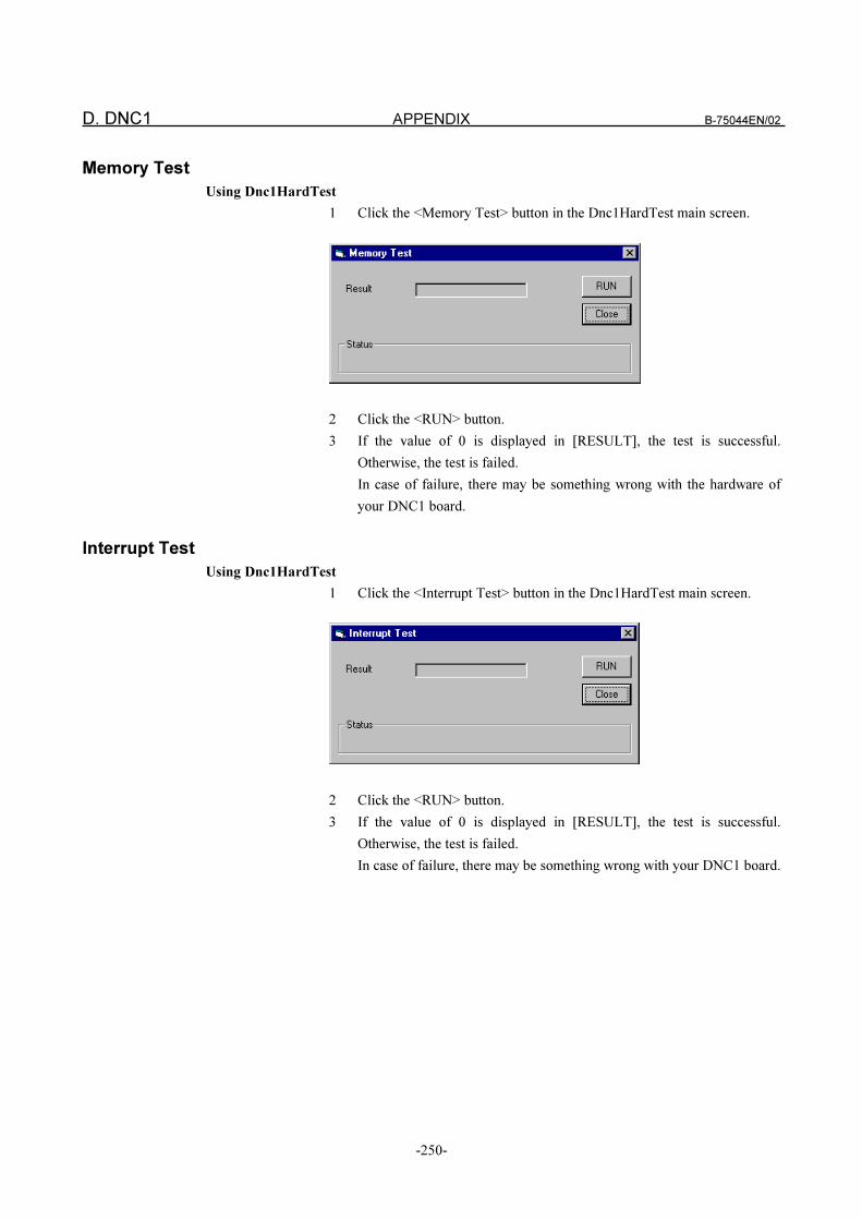
D. DNC1 APPENDIX B-75044EN/02
-250-
Memory Test
Using Dnc1HardTest
1 Click the <Memory Test> button in the Dnc1HardTest main screen.
2 Click the <RUN> button.
3 If the value of 0 is displayed in [RESULT], the test is successful.
Otherwise, the test is failed.
In case of failure, there may be something wrong with the hardware of
your DNC1 board.
Interrupt Test
Using Dnc1HardTest
1 Click the <Interrupt Test> button in the Dnc1HardTest main screen.
2 Click the <RUN> button.
3 If the value of 0 is displayed in [RESULT], the test is successful.
Otherwise, the test is failed.
In case of failure, there may be something wrong with your DNC1 board.
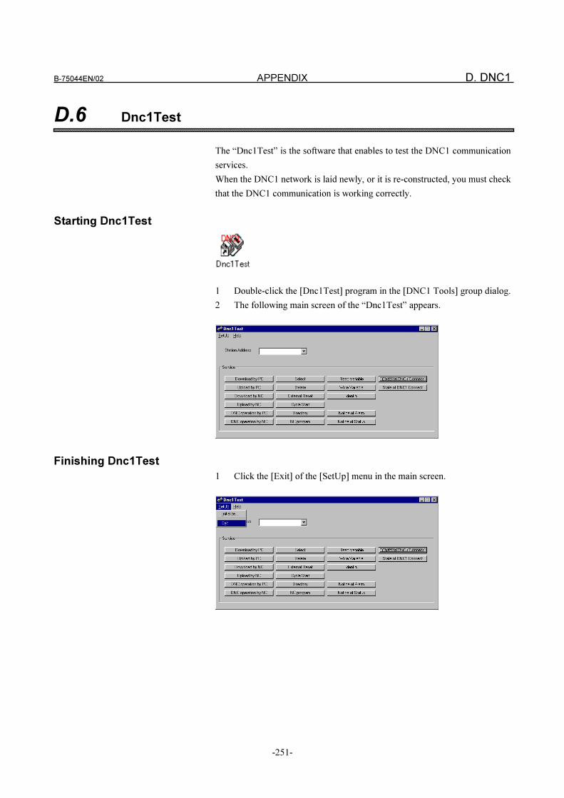
B-75044EN/02 APPENDIX D. DNC1
-251-
D.6 Dnc1Test
The “Dnc1Test” is the software that enables to test the DNC1 communication
services.
When the DNC1 network is laid newly, or it is re-constructed, you must check
that the DNC1 communication is working correctly.
Starting Dnc1Test
1 Double-click the [Dnc1Test] program in the [DNC1 Tools] group dialog.
2 The following main screen of the “Dnc1Test” appears.
Finishing Dnc1Test
1 Click the [Exit] of the [SetUp] menu in the main screen.
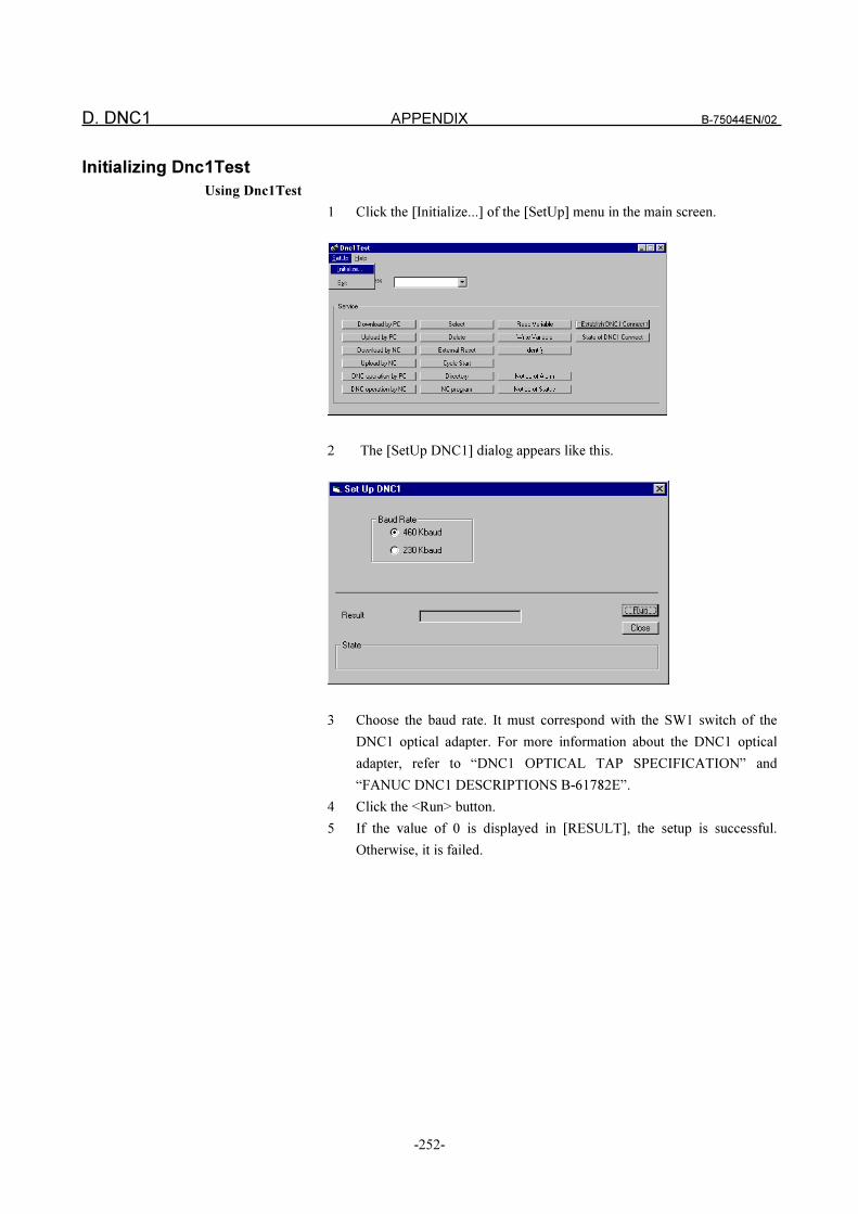
D. DNC1 APPENDIX B-75044EN/02
-252-
Initializing Dnc1Test
Using Dnc1Test
1 Click the [Initialize...] of the [SetUp] menu in the main screen.
2 The [SetUp DNC1] dialog appears like this.
3 Choose the baud rate. It must correspond with the SW1 switch of the
DNC1 optical adapter. For more information about the DNC1 optical
adapter, refer to “DNC1 OPTICAL TAP SPECIFICATION” and
“FANUC DNC1 DESCRIPTIONS B-61782E”.
4 Click the <Run> button.
5 If the value of 0 is displayed in [RESULT], the setup is successful.
Otherwise, it is failed.
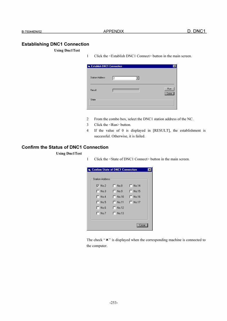
B-75044EN/02 APPENDIX D. DNC1
-253-
Establishing DNC1 Connection
Using Dnc1Test
1 Click the <Establish DNC1 Connect> button in the main screen.
2 From the combo box, select the DNC1 station address of the NC.
3 Click the <Run> button.
4 If the value of 0 is displayed in [RESULT], the establishment is
successful. Otherwise, it is failed.
Confirm the Status of DNC1 Connection
Using Dnc1Test
1 Click the <State of DNC1 Connect> button in the main screen.
The check “����” is displayed when the corresponding machine is connected to
the computer.
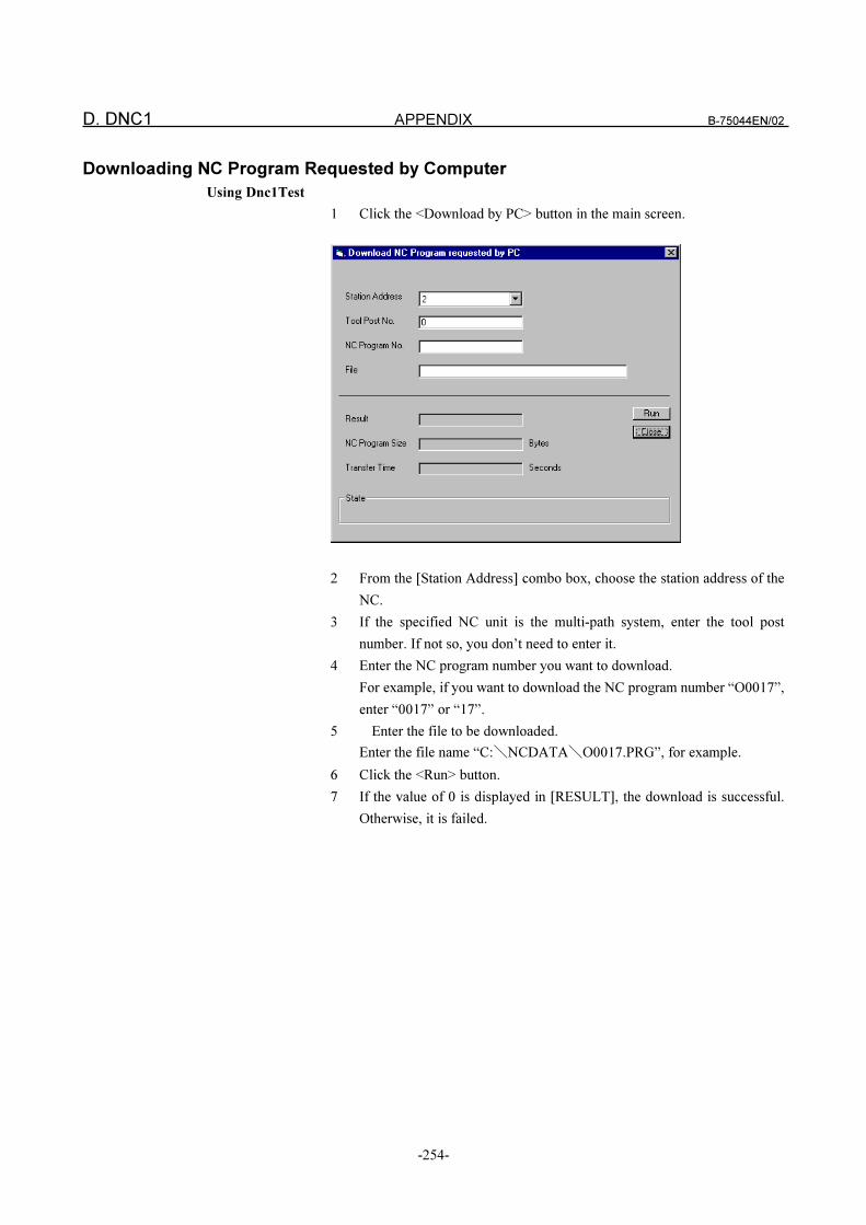
D. DNC1 APPENDIX B-75044EN/02
-254-
Downloading NC Program Requested by Computer
Using Dnc1Test
1 Click the <Download by PC> button in the main screen.
2 From the [Station Address] combo box, choose the station address of the
NC.
3 If the specified NC unit is the multi-path system, enter the tool post
number. If not so, you don’t need to enter it.
4 Enter the NC program number you want to download.
For example, if you want to download the NC program number “O0017”,
enter “0017” or “17”.
5 Enter the file to be downloaded.
Enter the file name “C:�NCDATA�O0017.PRG”, for example.
6 Click the <Run> button.
7 If the value of 0 is displayed in [RESULT], the download is successful.
Otherwise, it is failed.
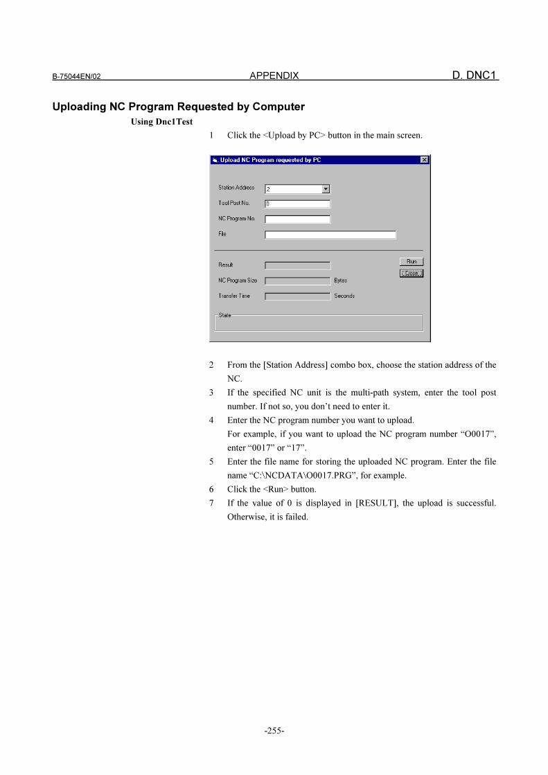
B-75044EN/02 APPENDIX D. DNC1
-255-
Uploading NC Program Requested by Computer
Using Dnc1Test
1 Click the <Upload by PC> button in the main screen.
2 From the [Station Address] combo box, choose the station address of the
NC.
3 If the specified NC unit is the multi-path system, enter the tool post
number. If not so, you don’t need to enter it.
4 Enter the NC program number you want to upload.
For example, if you want to upload the NC program number “O0017”,
enter “0017” or “17”.
5 Enter the file name for storing the uploaded NC program. Enter the file
name “C: NCDATA O0017.PRG”, for example.
6 Click the <Run> button.
7 If the value of 0 is displayed in [RESULT], the upload is successful.
Otherwise, it is failed.
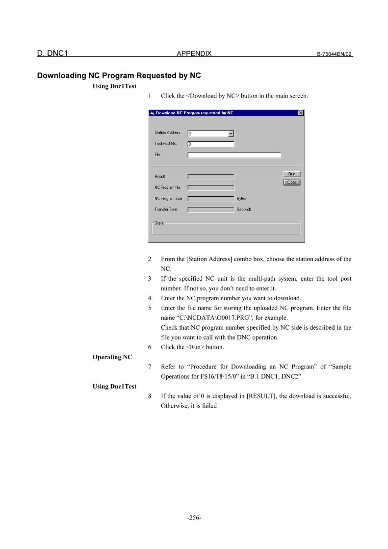
D. DNC1 APPENDIX B-75044EN/02
-256-
Downloading NC Program Requested by NC
Using Dnc1Test
1 Click the <Download by NC> button in the main screen.
2 From the [Station Address] combo box, choose the station address of the
NC.
3 If the specified NC unit is the multi-path system, enter the tool post
number. If not so, you don’t need to enter it.
4 Enter the NC program number you want to download.
5 Enter the file name for storing the uploaded NC program. Enter the file
name “C: NCDATA O0017.PRG”, for example.
Check that NC program number specified by NC side is described in the
file you want to call with the DNC operation.
6 Click the <Run> button.
Operating NC
7 Refer to “Procedure for Downloading an NC Program” of “Sample
Operations for FS16/18/15/0” in “B.1 DNC1, DNC2”.
Using Dnc1Test
8 If the value of 0 is displayed in [RESULT], the download is successful.
Otherwise, it is failed

B-75044EN/02 APPENDIX D. DNC1
-257-
Uploading NC Program Requested by NC
Using Dnc1Test
1 Click the <Upload by NC> button in the main screen.
2 From the [Station Address] combo box, choose the station address of the
NC.
3 If the selected NC unit is the multi-path system, enter the tool post
number. If not so, you don’t need to enter it.
4 Enter the file name for storing the uploaded NC program.
Enter the file name “C: NCDATA O0017.PRG”, for example.
Check that NC program number specified by NC side is described in the
file you want to call with the DNC operation.
5 Click the <Run> button.
Operating NC
6 Refer to “Procedure for Uploading an NC Program” of “Sample
Operations for FS16/18/15/0” in “B.1 DNC1, DNC2”.
Using Dnc1Test
7 If the value of 0 is displayed in [ RESULT], the upload is successful.
Otherwise, it is failed
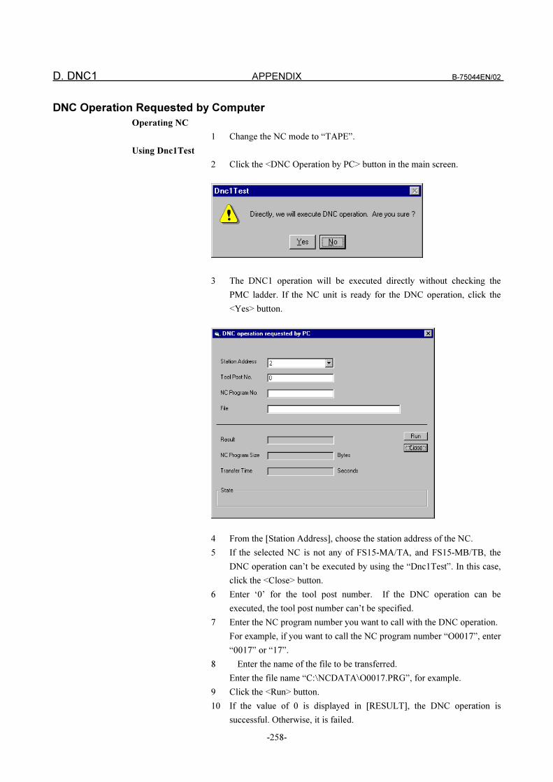
D. DNC1 APPENDIX B-75044EN/02
-258-
DNC Operation Requested by Computer
Operating NC
1 Change the NC mode to “TAPE”.
Using Dnc1Test
2 Click the <DNC Operation by PC> button in the main screen.
3 The DNC1 operation will be executed directly without checking the
PMC ladder. If the NC unit is ready for the DNC operation, click the
<Yes> button.
4 From the [Station Address], choose the station address of the NC.
5 If the selected NC is not any of FS15-MA/TA, and FS15-MB/TB, the
DNC operation can’t be executed by using the “Dnc1Test”. In this case,
click the <Close> button.
6 Enter ‘0’ for the tool post number. If the DNC operation can be
executed, the tool post number can’t be specified.
7 Enter the NC program number you want to call with the DNC operation.
For example, if you want to call the NC program number “O0017”, enter
“0017” or “17”.
8 Enter the name of the file to be transferred.
Enter the file name “C: NCDATA O0017.PRG”, for example.
9 Click the <Run> button.
10 If the value of 0 is displayed in [RESULT], the DNC operation is
successful. Otherwise, it is failed.
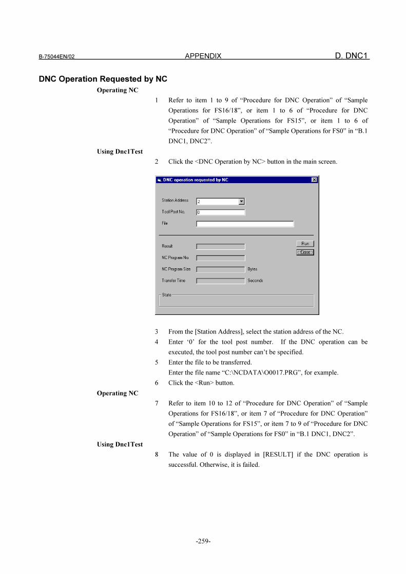
B-75044EN/02 APPENDIX D. DNC1
-259-
DNC Operation Requested by NC
Operating NC
1 Refer to item 1 to 9 of “Procedure for DNC Operation” of “Sample
Operations for FS16/18”, or item 1 to 6 of “Procedure for DNC
Operation” of “Sample Operations for FS15”, or item 1 to 6 of
“Procedure for DNC Operation” of “Sample Operations for FS0” in “B.1
DNC1, DNC2”.
Using Dnc1Test
2 Click the <DNC Operation by NC> button in the main screen.
3 From the [Station Address], select the station address of the NC.
4 Enter ‘0’ for the tool post number. If the DNC operation can be
executed, the tool post number can’t be specified.
5 Enter the file to be transferred.
Enter the file name “C: NCDATA O0017.PRG”, for example.
6 Click the <Run> button.
Operating NC
7 Refer to item 10 to 12 of “Procedure for DNC Operation” of “Sample
Operations for FS16/18”, or item 7 of “Procedure for DNC Operation”
of “Sample Operations for FS15”, or item 7 to 9 of “Procedure for DNC
Operation” of “Sample Operations for FS0” in “B.1 DNC1, DNC2”.
Using Dnc1Test
8 The value of 0 is displayed in [RESULT] if the DNC operation is
successful. Otherwise, it is failed.
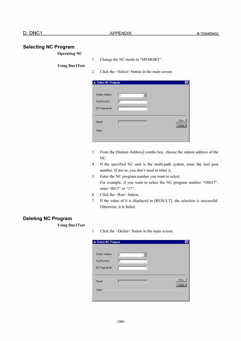
D. DNC1 APPENDIX B-75044EN/02
-260-
Selecting NC Program
Operating NC
1 Change the NC mode to “MEMORY”.
Using Dnc1Test
2 Click the <Select> button in the main screen.
3 From the [Station Address] combo box, choose the station address of the
NC.
4 If the specified NC unit is the multi-path system, enter the tool post
number. If not so, you don’t need to enter it.
5 Enter the NC program number you want to select.
For example, if you want to select the NC program number “O0017”,
enter “0017” or “17”.
6 Click the <Run> button.
7 If the value of 0 is displayed in [RESULT], the selection is successful.
Otherwise, it is failed.
Deleting NC Program
Using Dnc1Test
1 Click the <Delete> button in the main screen.
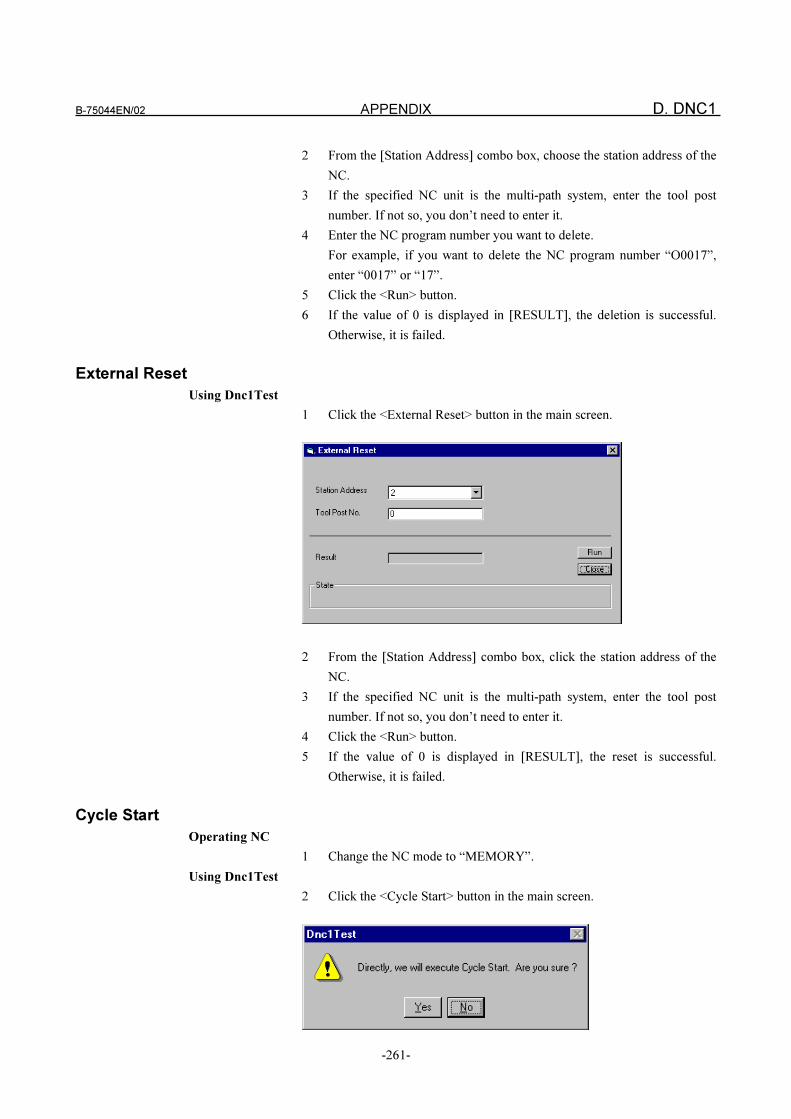
B-75044EN/02 APPENDIX D. DNC1
-261-
2 From the [Station Address] combo box, choose the station address of the
NC.
3 If the specified NC unit is the multi-path system, enter the tool post
number. If not so, you don’t need to enter it.
4 Enter the NC program number you want to delete.
For example, if you want to delete the NC program number “O0017”,
enter “0017” or “17”.
5 Click the <Run> button.
6 If the value of 0 is displayed in [RESULT], the deletion is successful.
Otherwise, it is failed.
External Reset
Using Dnc1Test
1 Click the <External Reset> button in the main screen.
2 From the [Station Address] combo box, click the station address of the
NC.
3 If the specified NC unit is the multi-path system, enter the tool post
number. If not so, you don’t need to enter it.
4 Click the <Run> button.
5 If the value of 0 is displayed in [RESULT], the reset is successful.
Otherwise, it is failed.
Cycle Start
Operating NC
1 Change the NC mode to “MEMORY”.
Using Dnc1Test
2 Click the <Cycle Start> button in the main screen.
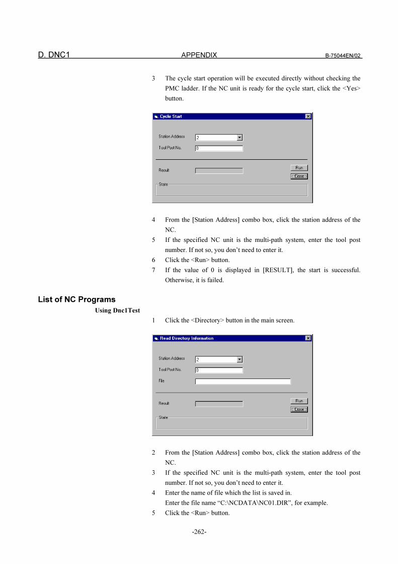
D. DNC1 APPENDIX B-75044EN/02
-262-
3 The cycle start operation will be executed directly without checking the
PMC ladder. If the NC unit is ready for the cycle start, click the <Yes>
button.
4 From the [Station Address] combo box, click the station address of the
NC.
5 If the specified NC unit is the multi-path system, enter the tool post
number. If not so, you don’t need to enter it.
6 Click the <Run> button.
7 If the value of 0 is displayed in [RESULT], the start is successful.
Otherwise, it is failed.
List of NC Programs
Using Dnc1Test
1 Click the <Directory> button in the main screen.
2 From the [Station Address] combo box, click the station address of the
NC.
3 If the specified NC unit is the multi-path system, enter the tool post
number. If not so, you don’t need to enter it.
4 Enter the name of file which the list is saved in.
Enter the file name “C: NCDATA NC01.DIR”, for example.
5 Click the <Run> button.
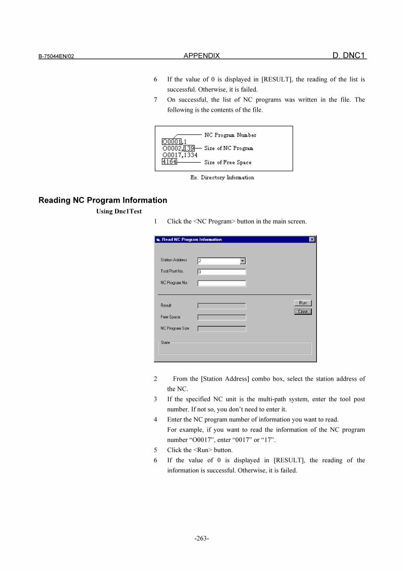
B-75044EN/02 APPENDIX D. DNC1
-263-
6 If the value of 0 is displayed in [RESULT], the reading of the list is
successful. Otherwise, it is failed.
7 On successful, the list of NC programs was written in the file. The
following is the contents of the file.
Reading NC Program Information
Using Dnc1Test
1 Click the <NC Program> button in the main screen.
2 From the [Station Address] combo box, select the station address of
the NC.
3 If the specified NC unit is the multi-path system, enter the tool post
number. If not so, you don’t need to enter it.
4 Enter the NC program number of information you want to read.
For example, if you want to read the information of the NC program
number “O0017”, enter “0017” or “17”.
5 Click the <Run> button.
6 If the value of 0 is displayed in [RESULT], the reading of the
information is successful. Otherwise, it is failed.
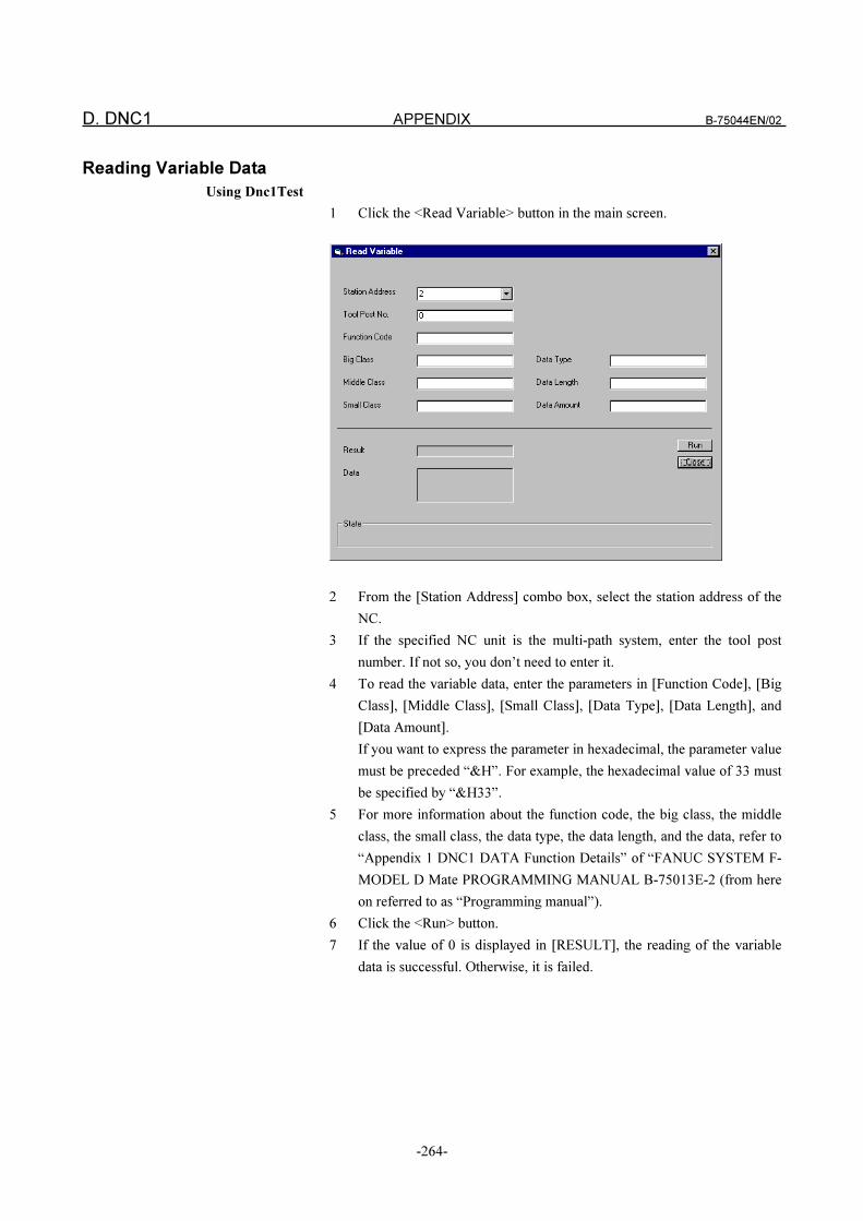
D. DNC1 APPENDIX B-75044EN/02
-264-
Reading Variable Data
Using Dnc1Test
1 Click the <Read Variable> button in the main screen.
2 From the [Station Address] combo box, select the station address of the
NC.
3 If the specified NC unit is the multi-path system, enter the tool post
number. If not so, you don’t need to enter it.
4 To read the variable data, enter the parameters in [Function Code], [Big
Class], [Middle Class], [Small Class], [Data Type], [Data Length], and
[Data Amount].
If you want to express the parameter in hexadecimal, the parameter value
must be preceded “&H”. For example, the hexadecimal value of 33 must
be specified by “&H33”.
5 For more information about the function code, the big class, the middle
class, the small class, the data type, the data length, and the data, refer to
“Appendix 1 DNC1 DATA Function Details” of “FANUC SYSTEM F-
MODEL D Mate PROGRAMMING MANUAL B-75013E-2 (from here
on referred to as “Programming manual”).
6 Click the <Run> button.
7 If the value of 0 is displayed in [RESULT], the reading of the variable
data is successful. Otherwise, it is failed.
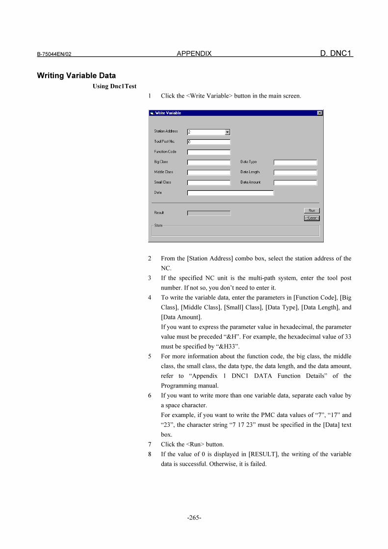
B-75044EN/02 APPENDIX D. DNC1
-265-
Writing Variable Data
Using Dnc1Test
1 Click the <Write Variable> button in the main screen.
2 From the [Station Address] combo box, select the station address of the
NC.
3 If the specified NC unit is the multi-path system, enter the tool post
number. If not so, you don’t need to enter it.
4 To write the variable data, enter the parameters in [Function Code], [Big
Class], [Middle Class], [Small] Class], [Data Type], [Data Length], and
[Data Amount].
If you want to express the parameter value in hexadecimal, the parameter
value must be preceded “&H”. For example, the hexadecimal value of 33
must be specified by “&H33”.
5 For more information about the function code, the big class, the middle
class, the small class, the data type, the data length, and the data amount,
refer to “Appendix 1 DNC1 DATA Function Details” of the
Programming manual.
6 If you want to write more than one variable data, separate each value by
a space character.
For example, if you want to write the PMC data values of “7”, “17” and
“23”, the character string “7 17 23” must be specified in the [Data] text
box.
7 Click the <Run> button.
8 If the value of 0 is displayed in [RESULT], the writing of the variable
data is successful. Otherwise, it is failed.
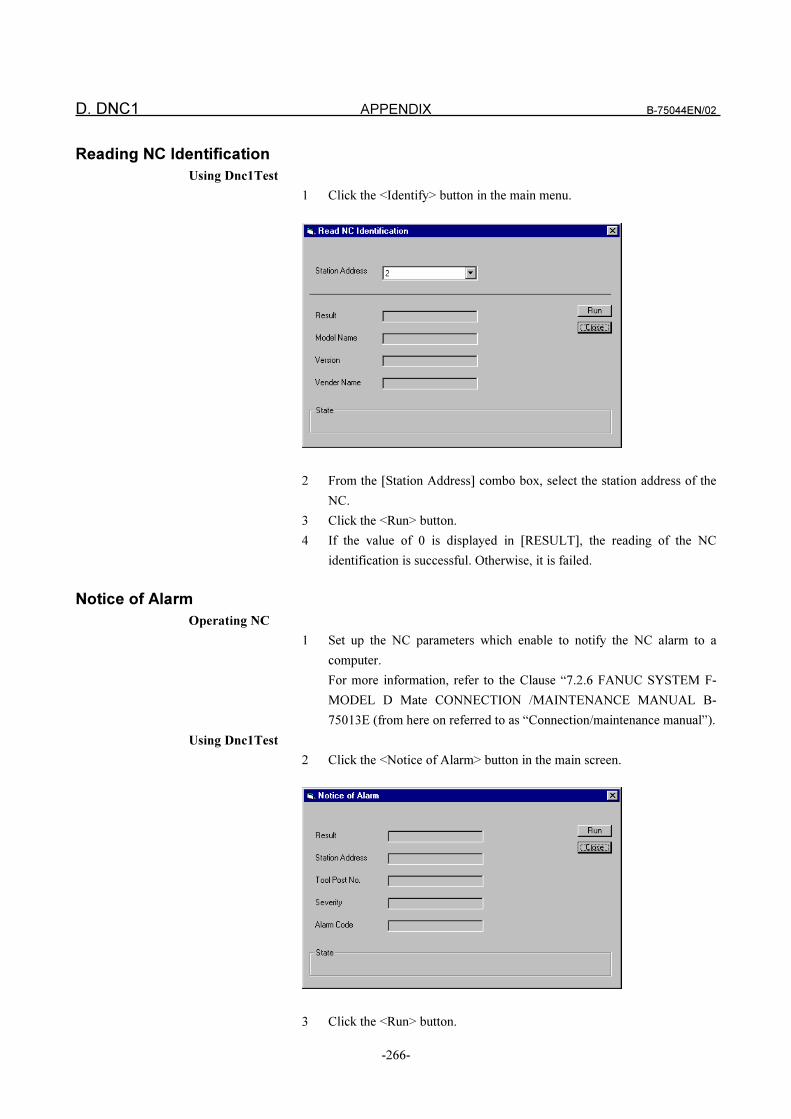
D. DNC1 APPENDIX B-75044EN/02
-266-
Reading NC Identification
Using Dnc1Test
1 Click the <Identify> button in the main menu.
2 From the [Station Address] combo box, select the station address of the
NC.
3 Click the <Run> button.
4 If the value of 0 is displayed in [RESULT], the reading of the NC
identification is successful. Otherwise, it is failed.
Notice of Alarm
Operating NC
1 Set up the NC parameters which enable to notify the NC alarm to a
computer.
For more information, refer to the Clause “7.2.6 FANUC SYSTEM F-
MODEL D Mate CONNECTION /MAINTENANCE MANUAL B-
75013E (from here on referred to as “Connection/maintenance manual”).
Using Dnc1Test
2 Click the <Notice of Alarm> button in the main screen.
3 Click the <Run> button.
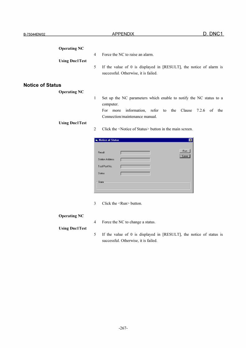
B-75044EN/02 APPENDIX D. DNC1
-267-
Operating NC
4 Force the NC to raise an alarm.
Using Dnc1Test
5 If the value of 0 is displayed in [RESULT], the notice of alarm is
successful. Otherwise, it is failed.
Notice of Status
Operating NC
1 Set up the NC parameters which enable to notify the NC status to a
computer.
For more information, refer to the Clause 7.2.6 of the
Connection/maintenance manual.
Using Dnc1Test
2 Click the <Notice of Status> button in the main screen.
3 Click the <Run> button.
Operating NC
4 Force the NC to change a status.
Using Dnc1Test
5 If the value of 0 is displayed in [RESULT], the notice of status is
successful. Otherwise, it is failed.
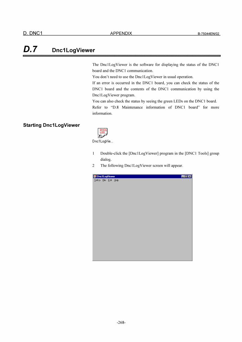
D. DNC1 APPENDIX B-75044EN/02
-268-
D.7 Dnc1LogViewer
The Dnc1LogViewer is the software for displaying the status of the DNC1
board and the DNC1 communication.
You don’t need to use the Dnc1LogViewer in usual operation.
If an error is occurred in the DNC1 board, you can check the status of the
DNC1 board and the contents of the DNC1 communication by using the
Dnc1LogViewer program.
You can also check the status by seeing the green LEDs on the DNC1 board.
Refer to “D.8 Maintenance information of DNC1 board” for more
information.
Starting Dnc1LogViewer
1 Double-click the [Dnc1LogViewer] program in the [DNC1 Tools] group
dialog.
2 The following Dnc1LogViewer screen will appear.
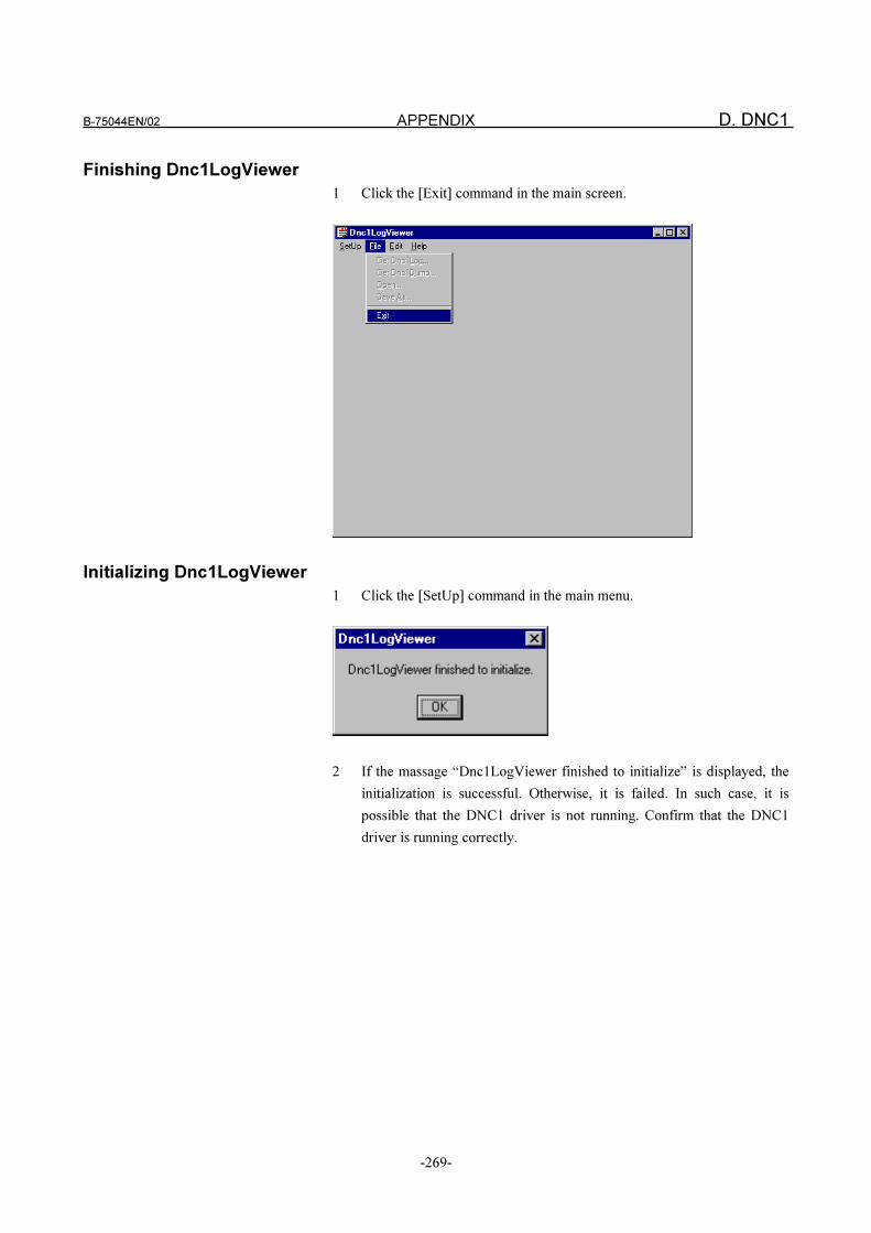
B-75044EN/02 APPENDIX D. DNC1
-269-
Finishing Dnc1LogViewer
1 Click the [Exit] command in the main screen.
Initializing Dnc1LogViewer
1 Click the [SetUp] command in the main menu.
2 If the massage “Dnc1LogViewer finished to initialize” is displayed, the
initialization is successful. Otherwise, it is failed. In such case, it is
possible that the DNC1 driver is not running. Confirm that the DNC1
driver is running correctly.
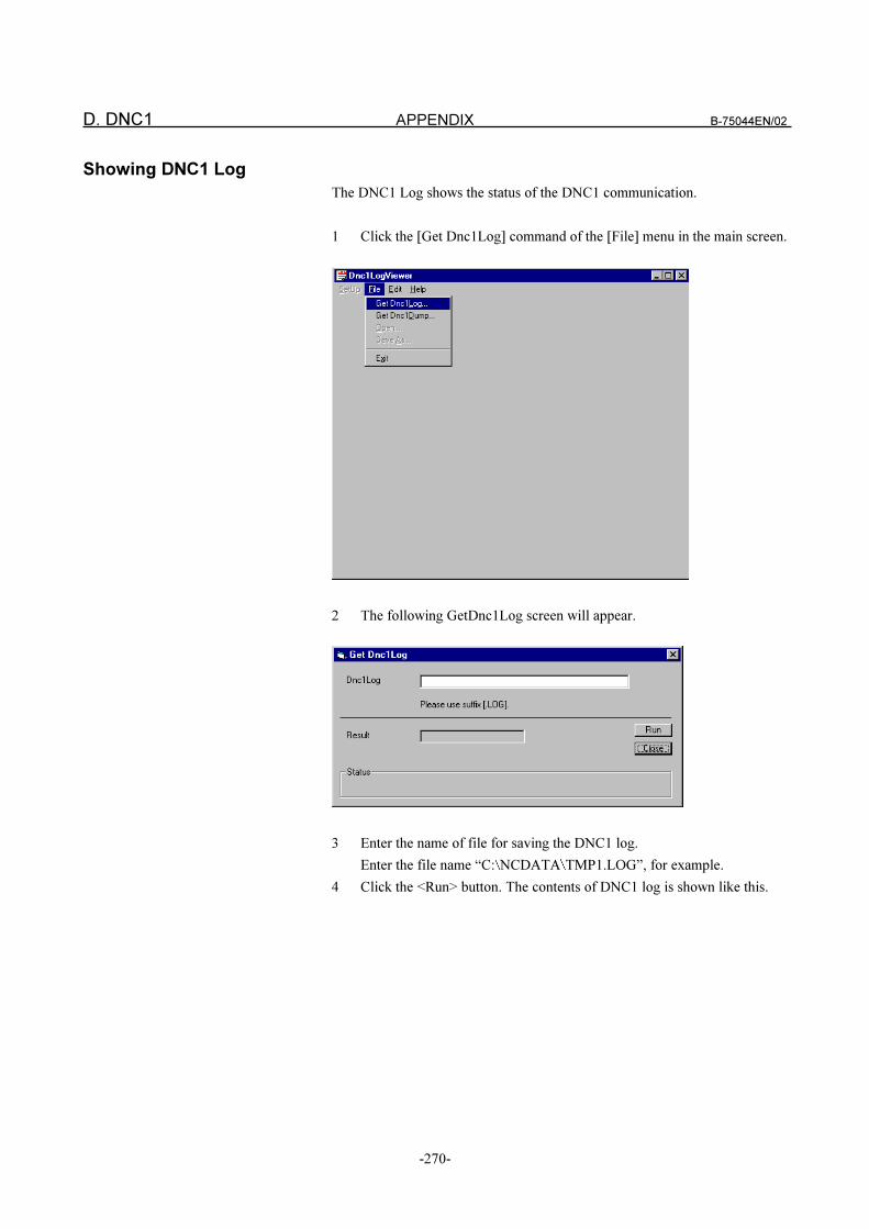
D. DNC1 APPENDIX B-75044EN/02
-270-
Showing DNC1 Log
The DNC1 Log shows the status of the DNC1 communication.
1 Click the [Get Dnc1Log] command of the [File] menu in the main screen.
2 The following GetDnc1Log screen will appear.
3 Enter the name of file for saving the DNC1 log.
Enter the file name “C: NCDATA TMP1.LOG”, for example.
4 Click the <Run> button. The contents of DNC1 log is shown like this.
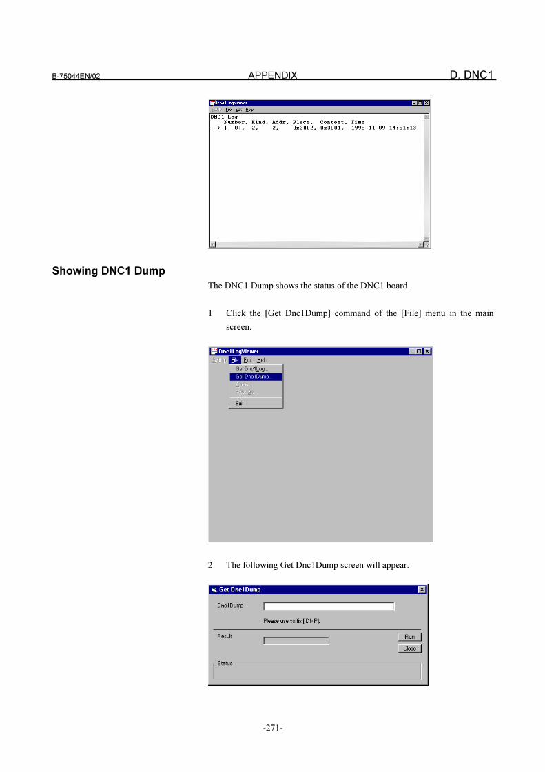
B-75044EN/02 APPENDIX D. DNC1
-271-
Showing DNC1 Dump
The DNC1 Dump shows the status of the DNC1 board.
1 Click the [Get Dnc1Dump] command of the [File] menu in the main
screen.
2 The following Get Dnc1Dump screen will appear.
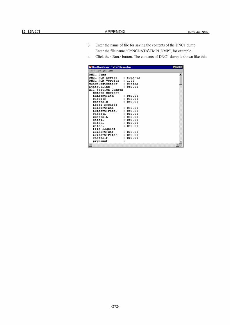
D. DNC1 APPENDIX B-75044EN/02
-272-
3 Enter the name of file for saving the contents of the DNC1 dump.
Enter the file name “C: NCDATA TMP1.DMP”, for example.
4 Click the <Run> button. The contents of DNC1 dump is shown like this.
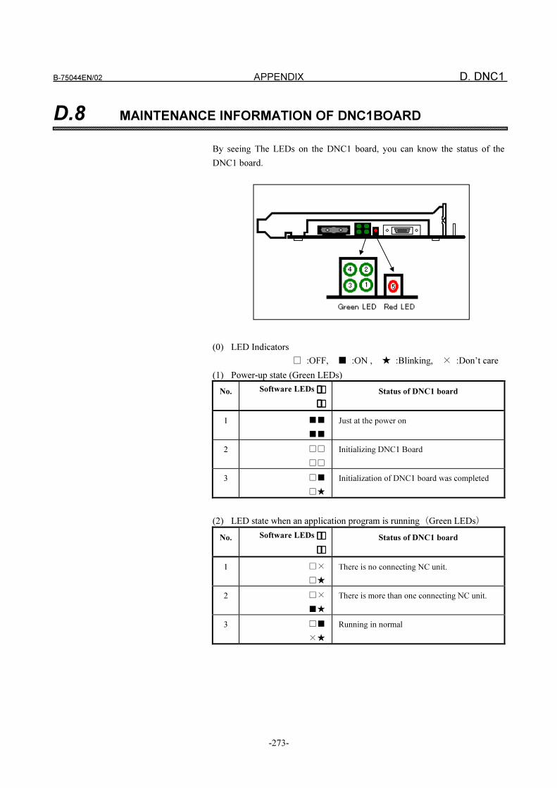
B-75044EN/02 APPENDIX D. DNC1
-273-
D.8 MAINTENANCE INFORMATION OF DNC1BOARD
By seeing The LEDs on the DNC1 board, you can know the status of the
DNC1 board.
(0) LED Indicators
� :OFF, � :ON , � :Blinking, :Don’t care
(1) Power-up state (Green LEDs)
No. Software LEDs �� �� � � ��
�� �� � � ��
Status of DNC1 board
1 ��
��
Just at the power on
2 ��
��
Initializing DNC1 Board
3 ��
��
Initialization of DNC1 board was completed
(2) LED state when an application program is running�Green LEDs
No. Software LEDs �� �� � � ��
�� �� � � ��
Status of DNC1 board
1 ��
��
There is no connecting NC unit.
2 ��
��
There is more than one connecting NC unit.
3 ��
��
Running in normal
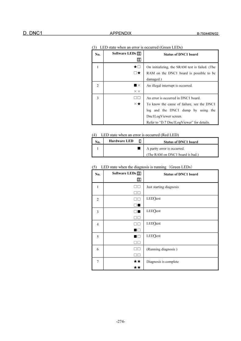
D. DNC1 APPENDIX B-75044EN/02
-274-
(3) LED state when an error is occurred (Green LEDs)
No. Software LEDs �� �� � � ��
�� �� � � ��
Status of DNC1 board
1 ��
��
On initializing, the SRAM test is failed. (The
RAM on the DNC1 board is possible to be
damaged.)
2 ��
��
An illegal interrupt is occurred.
3 ��
��
An error is occurred in DNC1 board.
To know the cause of failure, see the DNC1
log and the DNC1 dump by using the
Dnc1LogViewer screen.
Refer to “D.7 Dnc1LogViewer” for details.
(4) LED state when an error is occurred (Red LED)
No. Hardware LED �� �� Status of DNC1 board
1 � A parity error is occurred.
(The RAM on DNC1 board is bad.)
(5) LED state when the diagnosis is running�Green LEDs
No. Software LEDs �� �� � � ��
�� �� � � ��
Status of DNC1 board
1 ��
��
Just starting diagnosis
2 ��
��
LED � test
3 ��
��
LED � test
4 ��
��
LED � test
5 ��
��
LED � test
6 ��
��
(Running diagnosis )
7 ��
��
Diagnosis is complete
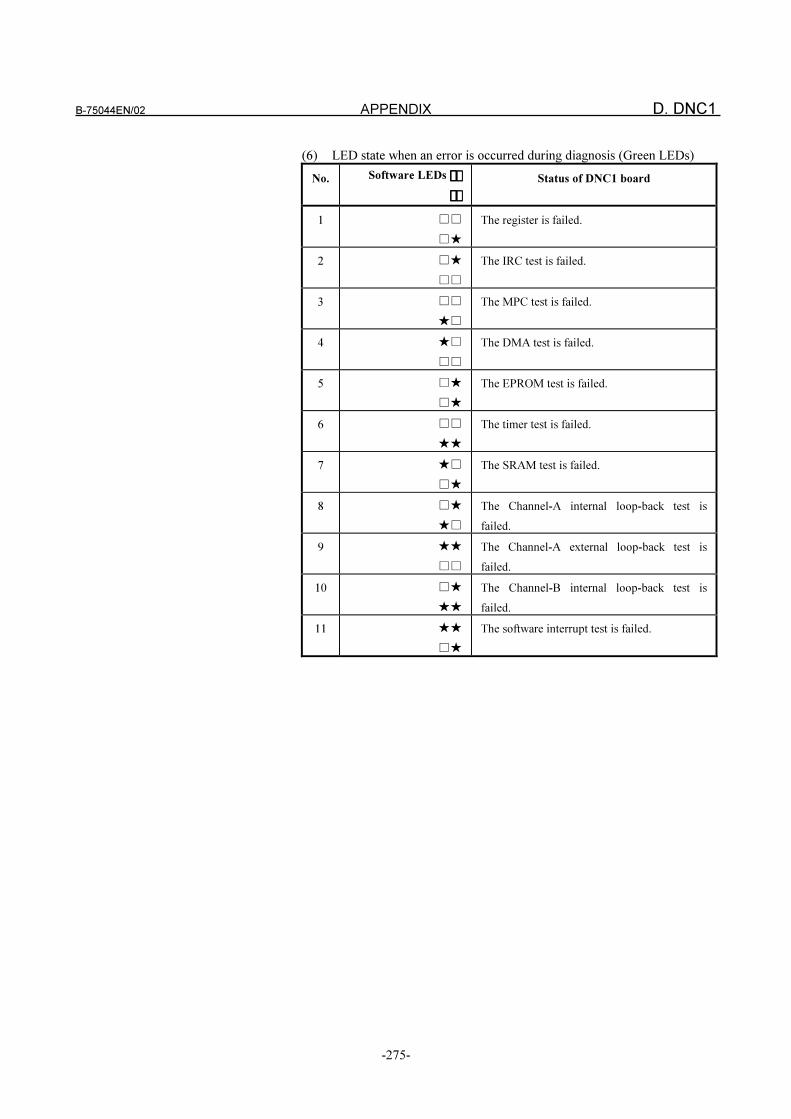
B-75044EN/02 APPENDIX D. DNC1
-275-
(6) LED state when an error is occurred during diagnosis (Green LEDs)
No. Software LEDs �� �� � � ��
�� �� � � ��
Status of DNC1 board
1 ��
��
The register is failed.
2 ��
��
The IRC test is failed.
3 ��
��
The MPC test is failed.
4 ��
��
The DMA test is failed.
5 ��
��
The EPROM test is failed.
6 ��
��
The timer test is failed.
7 ��
��
The SRAM test is failed.
8 ��
��
The Channel-A internal loop-back test is
failed.
9 ��
��
The Channel-A external loop-back test is
failed.
10 ��
��
The Channel-B internal loop-back test is
failed.
11 ��
��
The software interrupt test is failed.
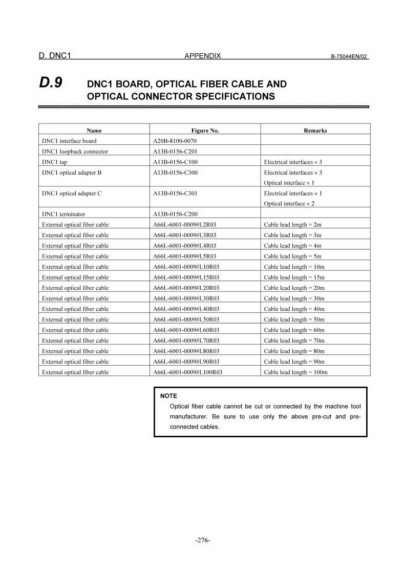
D. DNC1 APPENDIX B-75044EN/02
-276-
D.9 DNC1 BOARD, OPTICAL FIBER CABLE AND
OPTICAL CONNECTOR SPECIFICATIONS
Name Figure No. Remarks
DNC1 interface board A20B-8100-0070
DNC1 loopback connector A13B-0156-C201
DNC1 tap A13B-0156-C100 Electrical interfaces � 3
DNC1 optical adapter B A13B-0156-C300 Electrical interfaces � 3
Optical interface � 1
DNC1 optical adapter C A13B-0156-C301 Electrical interfaces � 1
Optical interface � 2
DNC1 terminator A13B-0156-C200
External optical fiber cable A66L-6001-0009#L2R03 Cable lead length = 2m
External optical fiber cable A66L-6001-0009#L3R03 Cable lead length = 3m
External optical fiber cable A66L-6001-0009#L4R03 Cable lead length = 4m
External optical fiber cable A66L-6001-0009#L5R03 Cable lead length = 5m
External optical fiber cable A66L-6001-0009#L10R03 Cable lead length = 10m
External optical fiber cable A66L-6001-0009#L15R03 Cable lead length = 15m
External optical fiber cable A66L-6001-0009#L20R03 Cable lead length = 20m
External optical fiber cable A66L-6001-0009#L30R03 Cable lead length = 30m
External optical fiber cable A66L-6001-0009#L40R03 Cable lead length = 40m
External optical fiber cable A66L-6001-0009#L50R03 Cable lead length = 50m
External optical fiber cable A66L-6001-0009#L60R03 Cable lead length = 60m
External optical fiber cable A66L-6001-0009#L70R03 Cable lead length = 70m
External optical fiber cable A66L-6001-0009#L80R03 Cable lead length = 80m
External optical fiber cable A66L-6001-0009#L90R03 Cable lead length = 90m
External optical fiber cable A66L-6001-0009#L100R03 Cable lead length = 100m
NOTE
Optical fiber cable cannot be cut or connected by the machine tool
manufacturer. Be sure to use only the above pre-cut and pre-
connected cables.
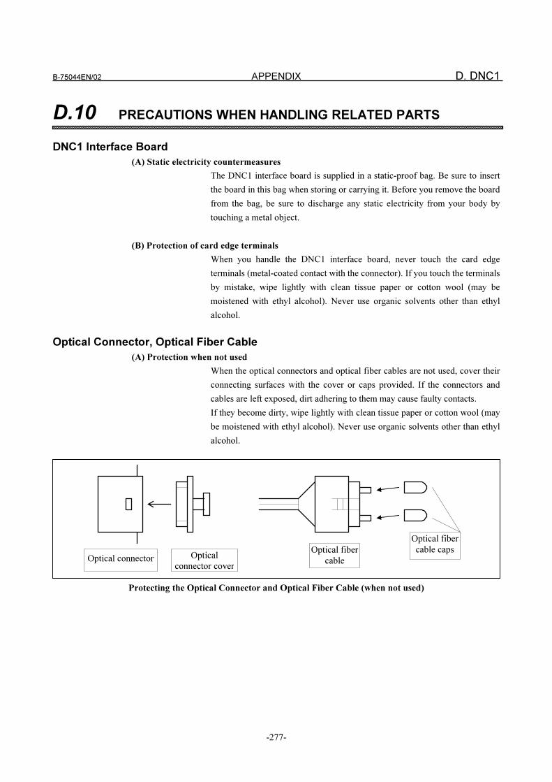
B-75044EN/02 APPENDIX D. DNC1
-277-
D.10 PRECAUTIONS WHEN HANDLING RELATED PARTS
DNC1 Interface Board
(A) Static electricity countermeasures
The DNC1 interface board is supplied in a static-proof bag. Be sure to insert
the board in this bag when storing or carrying it. Before you remove the board
from the bag, be sure to discharge any static electricity from your body by
touching a metal object.
(B) Protection of card edge terminals
When you handle the DNC1 interface board, never touch the card edge
terminals (metal-coated contact with the connector). If you touch the terminals
by mistake, wipe lightly with clean tissue paper or cotton wool (may be
moistened with ethyl alcohol). Never use organic solvents other than ethyl
alcohol.
Optical Connector, Optical Fiber Cable
(A) Protection when not used
When the optical connectors and optical fiber cables are not used, cover their
connecting surfaces with the cover or caps provided. If the connectors and
cables are left exposed, dirt adhering to them may cause faulty contacts.
If they become dirty, wipe lightly with clean tissue paper or cotton wool (may
be moistened with ethyl alcohol). Never use organic solvents other than ethyl
alcohol.
Protecting the Optical Connector and Optical Fiber Cable (when not used)
Optical connector Optical
connector cover
Optical fiber
cable capsOptical fiber
cable
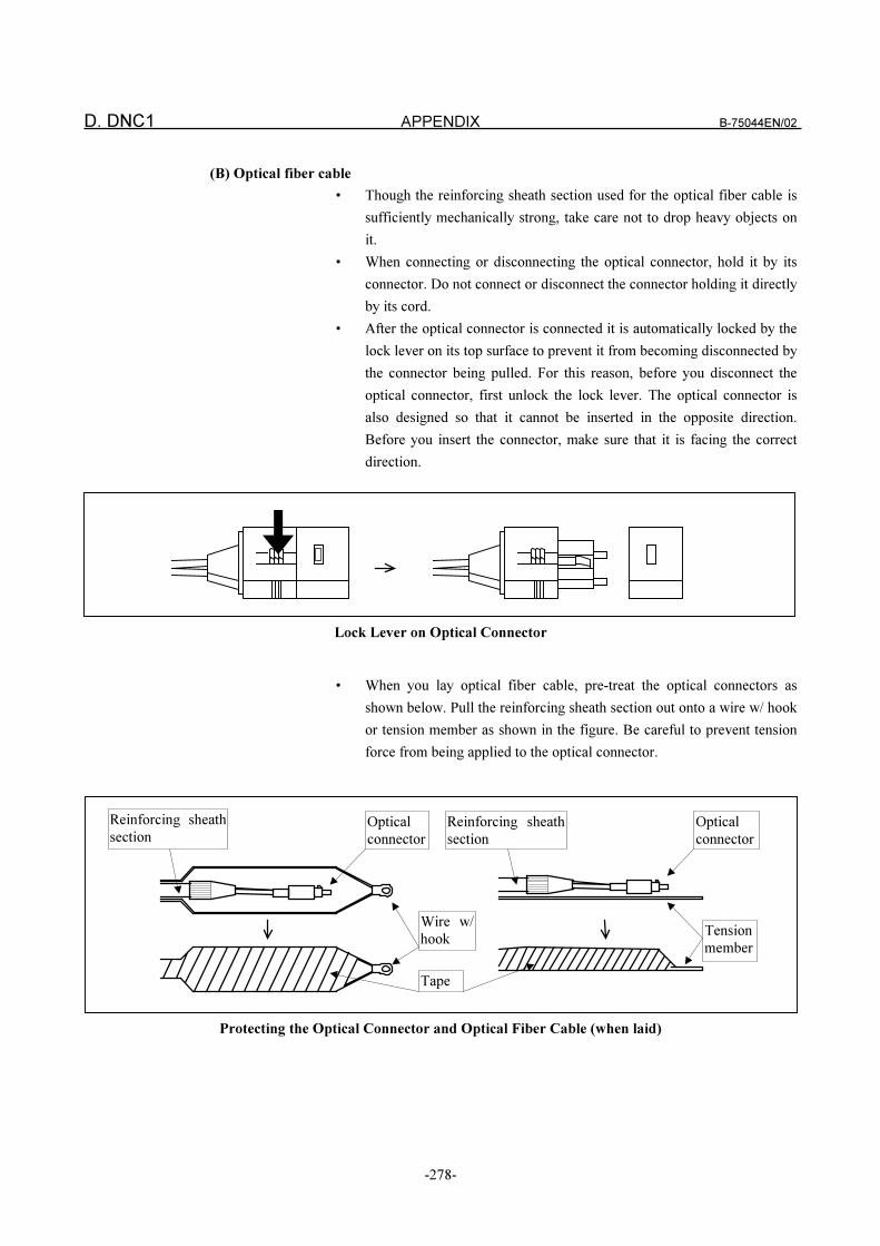
D. DNC1 APPENDIX B-75044EN/02
-278-
(B) Optical fiber cable
• Though the reinforcing sheath section used for the optical fiber cable is
sufficiently mechanically strong, take care not to drop heavy objects on
it.
• When connecting or disconnecting the optical connector, hold it by its
connector. Do not connect or disconnect the connector holding it directly
by its cord.
• After the optical connector is connected it is automatically locked by the
lock lever on its top surface to prevent it from becoming disconnected by
the connector being pulled. For this reason, before you disconnect the
optical connector, first unlock the lock lever. The optical connector is
also designed so that it cannot be inserted in the opposite direction.
Before you insert the connector, make sure that it is facing the correct
direction.
Lock Lever on Optical Connector
• When you lay optical fiber cable, pre-treat the optical connectors as
shown below. Pull the reinforcing sheath section out onto a wire w/ hook
or tension member as shown in the figure. Be careful to prevent tension
force from being applied to the optical connector.
Protecting the Optical Connector and Optical Fiber Cable (when laid)
Optical
connector
Optical
connector
Wire w/
hook
Tape
Tension
member
Reinforcing sheath
section
Reinforcing sheath
section
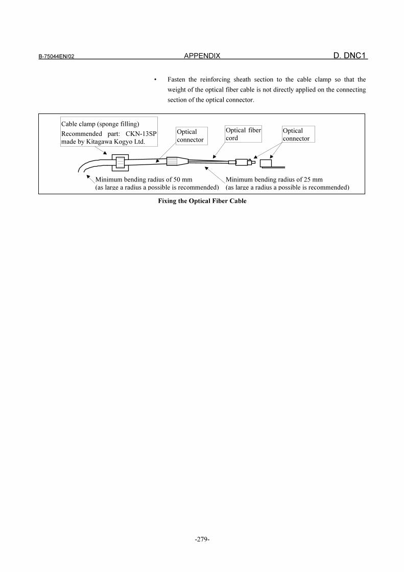
B-75044EN/02 APPENDIX D. DNC1
-279-
• Fasten the reinforcing sheath section to the cable clamp so that the
weight of the optical fiber cable is not directly applied on the connecting
section of the optical connector.
Fixing the Optical Fiber Cable
Optical
connector
Optical fiber
cord
Cable clamp (sponge filling)
Recommended part: CKN-13SP
made by Kitagawa Kogyo Ltd.
Optical
connector
Minimum bending radius of 25 mm
(as large a radius a possible is recommended)
Minimum bending radius of 50 mm
(as large a radius a possible is recommended)
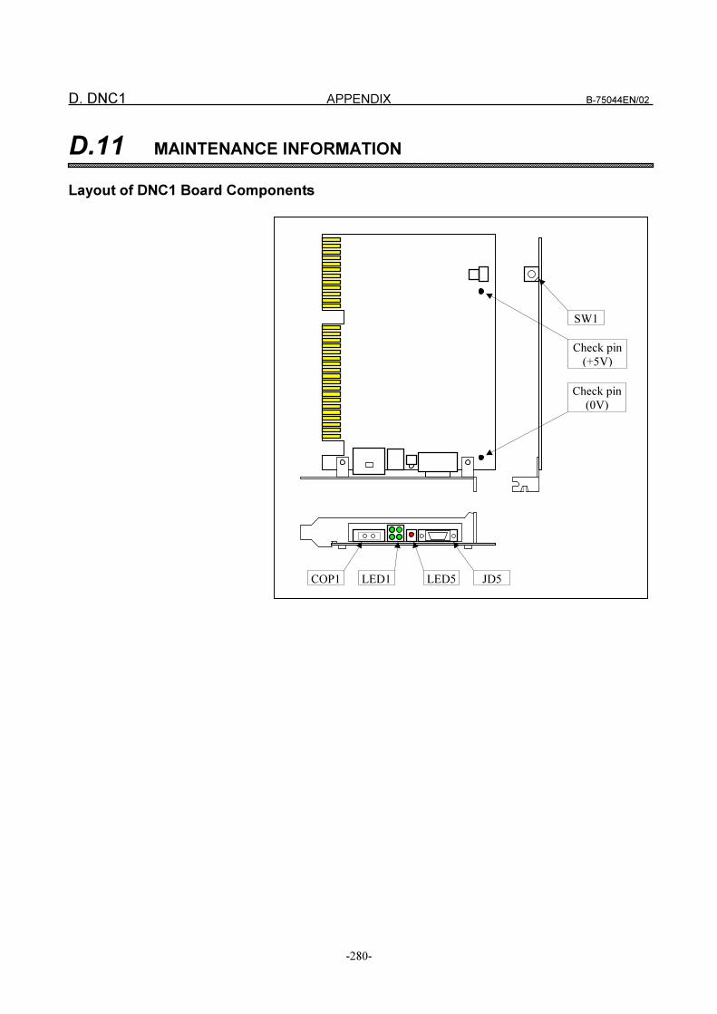
D. DNC1 APPENDIX B-75044EN/02
-280-
D.11 MAINTENANCE INFORMATION
Layout of DNC1 Board Components
LED1COP1
SW1
Check pin
(+5V)
Check pin
(0V)
JD5LED5
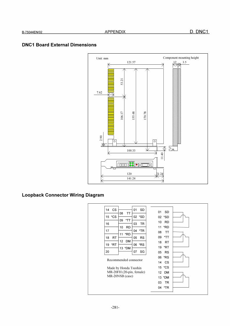
B-75044EN/02 APPENDIX D. DNC1
-281-
DNC1 Board External Dimensions
53.21
170.78
155.48
106.17
2.90
11.40
Component mounting height
3.512121.57
7.62
21.24
100.33
120
141.24
Unit: mm
Loopback Connector Wiring Diagram
01 SD14 CS
08 TT
02 *SD
09 *TT
15 *CS
03 TR16
04 *TR
10 RD
17
11 *RD
05 RS
12 DM
18 RT
06 *RS19 *RT
07 SG
13 *DM
20
01 SD
02 *SD
10 RD
11 *RD
08 TT
09 *TT
18 RT
19 *RT
05 RS
06 *RS
14 CS
15 *CS
12 DM
13 *DM
03 TR
04 *TR
Recommended connector
Made by Honda Tsushin
MR-20FH (20-pin, female)
MR-20NSB (case)

ADDITIONAL
INFORMATION
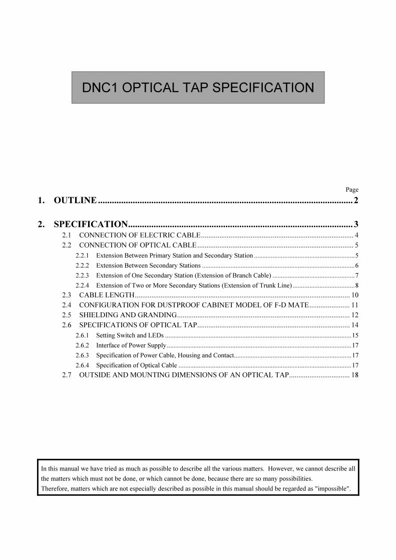
DNC1 OPTICAL TAP SPECIFICATION
Page
1. OUTLINE..............................................................................................................2
2. SPECIFICATION.................................................................................................3
2.1 CONNECTION OF ELECTRIC CABLE................................................................................... 4
2.2 CONNECTION OF OPTICAL CABLE..................................................................................... 5
2.2.1 Extension Between Primary Station and Secondary Station ............................................................5
2.2.2 Extension Between Secondary Stations ...........................................................................................6
2.2.3 Extension of One Secondary Station (Extension of Branch Cable) .................................................7
2.2.4 Extension of Two or More Secondary Stations (Extension of Trunk Line) .....................................8
2.3 CABLE LENGTH..................................................................................................................... 10
2.4 CONFIGURATION FOR DUSTPROOF CABINET MODEL OF F-D MATE...................... 11
2.5 SHIELDING AND GRANDING.............................................................................................. 12
2.6 SPECIFICATIONS OF OPTICAL TAP................................................................................... 14
2.6.1 Setting Switch and LEDs ...............................................................................................................15
2.6.2 Interface of Power Supply..............................................................................................................17
2.6.3 Specification of Power Cable, Housing and Contact......................................................................17
2.6.4 Specification of Optical Cable .......................................................................................................17
2.7 OUTSIDE AND MOUNTING DIMENSIONS OF AN OPTICAL TAP................................. 18
In this manual we have tried as much as possible to describe all the various matters. However, we cannot describe all
the matters which must not be done, or which cannot be done, because there are so many possibilities.
Therefore, matters which are not especially described as possible in this manual should be regarded as "impossible".

1. OUTLINE B-75044EN/02
-2-
1 OUTLINE
The optical tap is an adapter used in the FANUC-developed high-speed
network DNC1 (connection mode 1). It connects two taps and a node using
optical fiber cable.
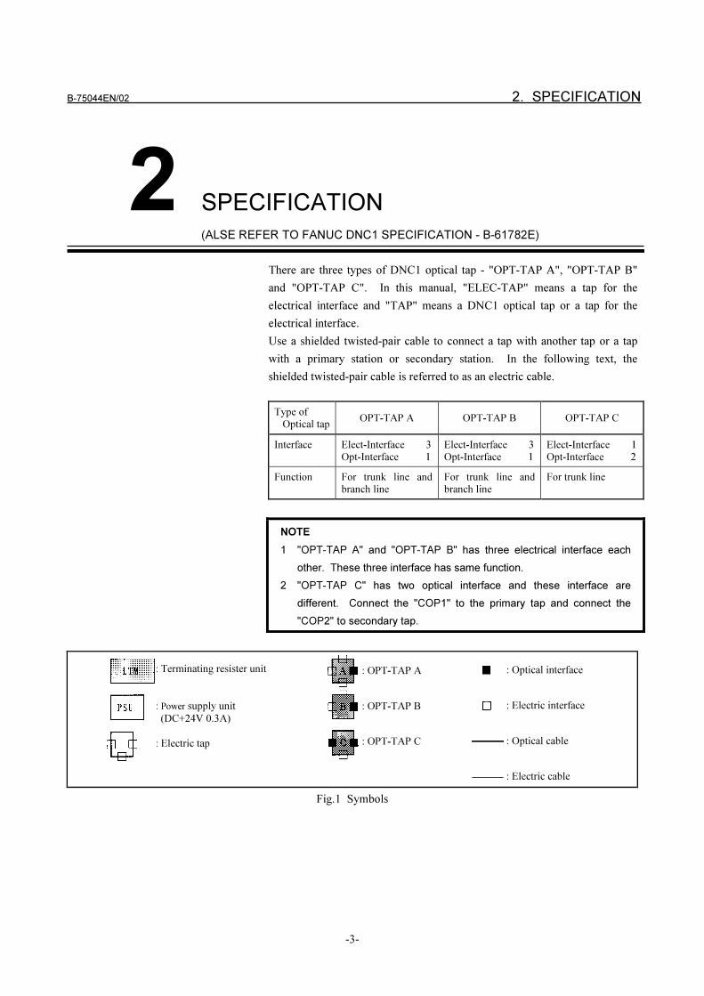
B-75044EN/02 2. SPECIFICATION
-3-
2 SPECIFICATION
(ALSE REFER TO FANUC DNC1 SPECIFICATION - B-61782E)
There are three types of DNC1 optical tap - "OPT-TAP A", "OPT-TAP B"
and "OPT-TAP C". In this manual, "ELEC-TAP" means a tap for the
electrical interface and "TAP" means a DNC1 optical tap or a tap for the
electrical interface.
Use a shielded twisted-pair cable to connect a tap with another tap or a tap
with a primary station or secondary station. In the following text, the
shielded twisted-pair cable is referred to as an electric cable.
Type of
Optical tapOPT-TAP A OPT-TAP B OPT-TAP C
Interface Elect-Interface 3
Opt-Interface 1
Elect-Interface 3
Opt-Interface 1
Elect-Interface 1
Opt-Interface 2
Function For trunk line and
branch line
For trunk line and
branch line
For trunk line
NOTE
1 "OPT-TAP A" and "OPT-TAP B" has three electrical interface each
other. These three interface has same function.
2 "OPT-TAP C" has two optical interface and these interface are
different. Connect the "COP1" to the primary tap and connect the
"COP2" to secondary tap.
Fig.1 Symbols
: Terminating resister unit
: Power supply unit
(DC+24V 0.3A)
: Electric tap
: OPT-TAP A
: OPT-TAP B
: OPT-TAP C
: Optical interface
: Electric interface
: Optical cable
: Electric cable
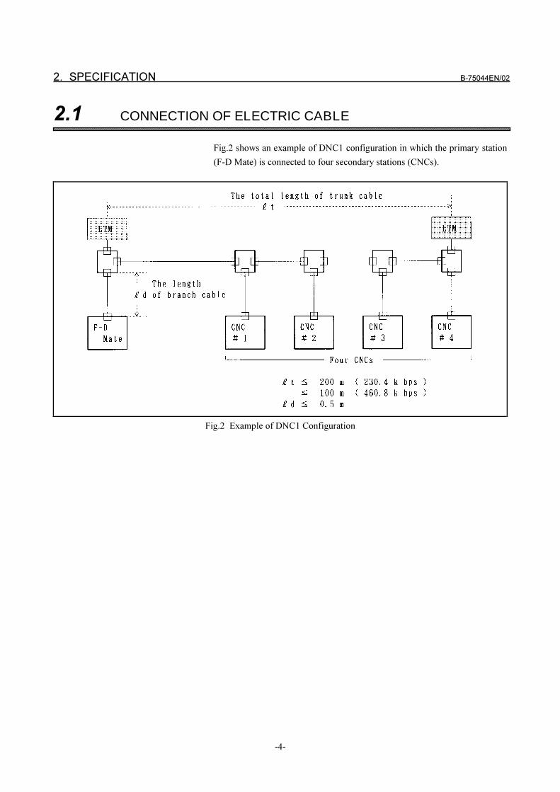
2. SPECIFICATION B-75044EN/02
-4-
2.1 CONNECTION OF ELECTRIC CABLE
Fig.2 shows an example of DNC1 configuration in which the primary station
(F-D Mate) is connected to four secondary stations (CNCs).
Fig.2 Example of DNC1 Configuration
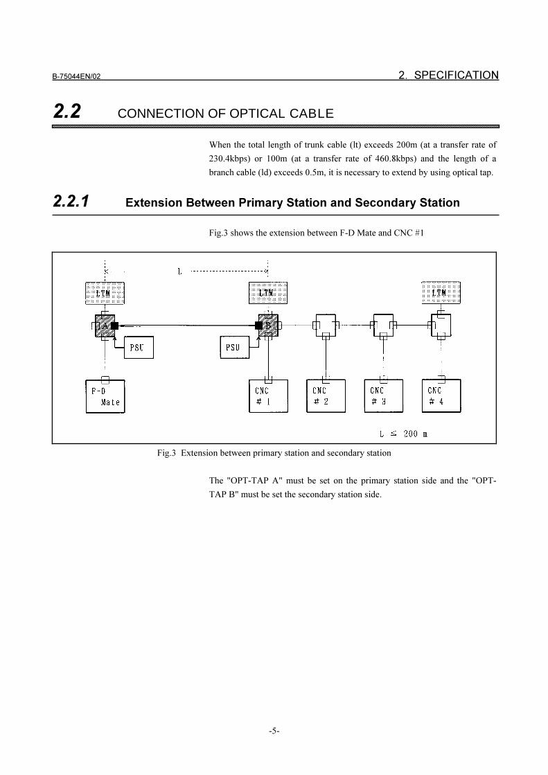
B-75044EN/02 2. SPECIFICATION
-5-
2.2 CONNECTION OF OPTICAL CABLE
When the total length of trunk cable (lt) exceeds 200m (at a transfer rate of
230.4kbps) or 100m (at a transfer rate of 460.8kbps) and the length of a
branch cable (ld) exceeds 0.5m, it is necessary to extend by using optical tap.
2.2.1 Extension Between Primary Station and Secondary Station
Fig.3 shows the extension between F-D Mate and CNC #1
Fig.3 Extension between primary station and secondary station
The "OPT-TAP A" must be set on the primary station side and the "OPT-
TAP B" must be set the secondary station side.
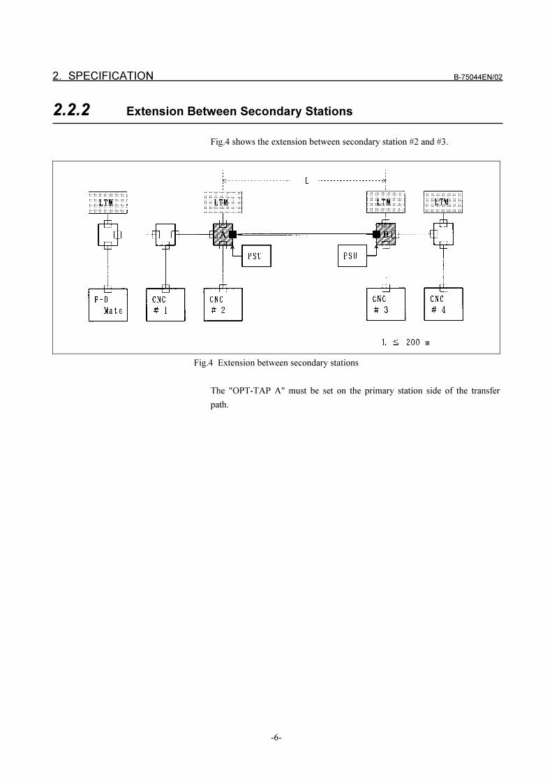
2. SPECIFICATION B-75044EN/02
-6-
2.2.2 Extension Between Secondary Stations
Fig.4 shows the extension between secondary station #2 and #3.
Fig.4 Extension between secondary stations
The "OPT-TAP A" must be set on the primary station side of the transfer
path.
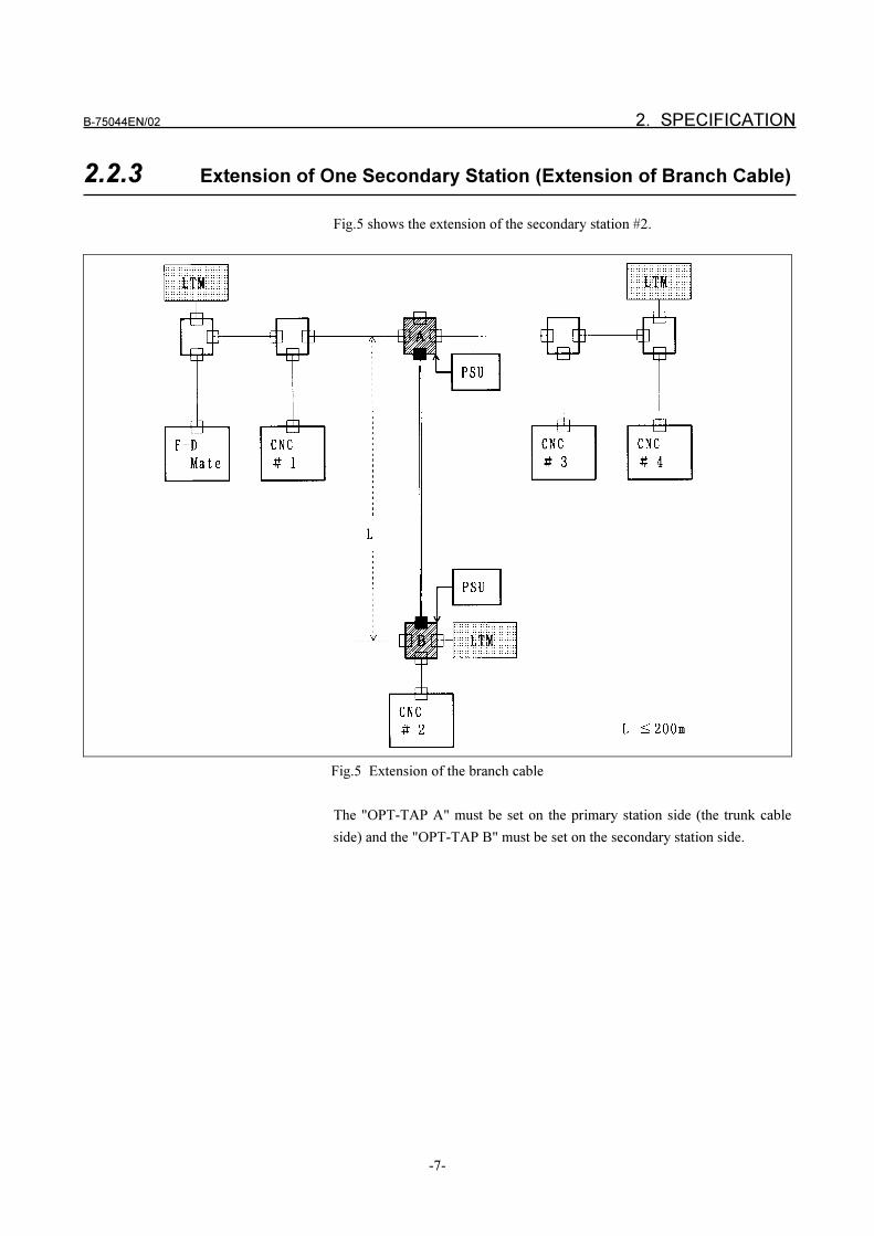
B-75044EN/02 2. SPECIFICATION
-7-
2.2.3 Extension of One Secondary Station (Extension of Branch Cable)
Fig.5 shows the extension of the secondary station #2.
Fig.5 Extension of the branch cable
The "OPT-TAP A" must be set on the primary station side (the trunk cable
side) and the "OPT-TAP B" must be set on the secondary station side.
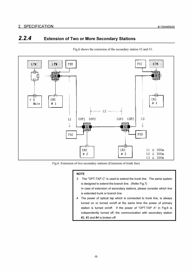
2. SPECIFICATION B-75044EN/02
-8-
2.2.4 Extension of Two or More Secondary Stations
Fig.6 shows the extension of the secondary station #2 and #3.
Fig.6 Extension of two secondary stations (Extension of trunk line)
NOTE
3 The "OPT-TAP C" is used to extend the trunk line. The same system
is designed to extend the branch line. (Refer Fig.7)
In case of extension of secondary stations, please consider which line
is extended trunk or branch line.
4 The power of optical tap which is connected to trunk line, is always
turned on or turned on/off at the same time the power of primary
station is turned on/off. If the power of "OPT-TAP A" in Fig.6 is
independently turned off, the communication with secondary station
#2, #3 and #4 is broken off.
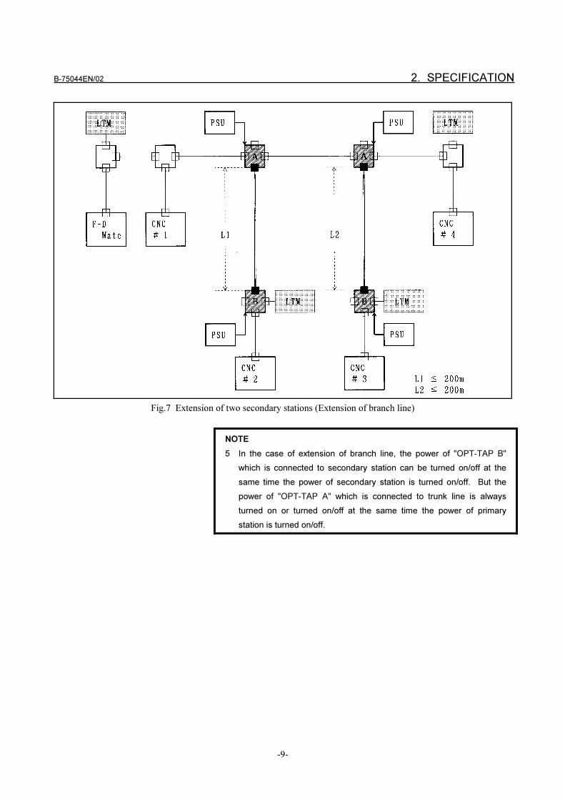
B-75044EN/02 2. SPECIFICATION
-9-
Fig.7 Extension of two secondary stations (Extension of branch line)
NOTE
5 In the case of extension of branch line, the power of "OPT-TAP B"
which is connected to secondary station can be turned on/off at the
same time the power of secondary station is turned on/off. But the
power of "OPT-TAP A" which is connected to trunk line is always
turned on or turned on/off at the same time the power of primary
station is turned on/off.
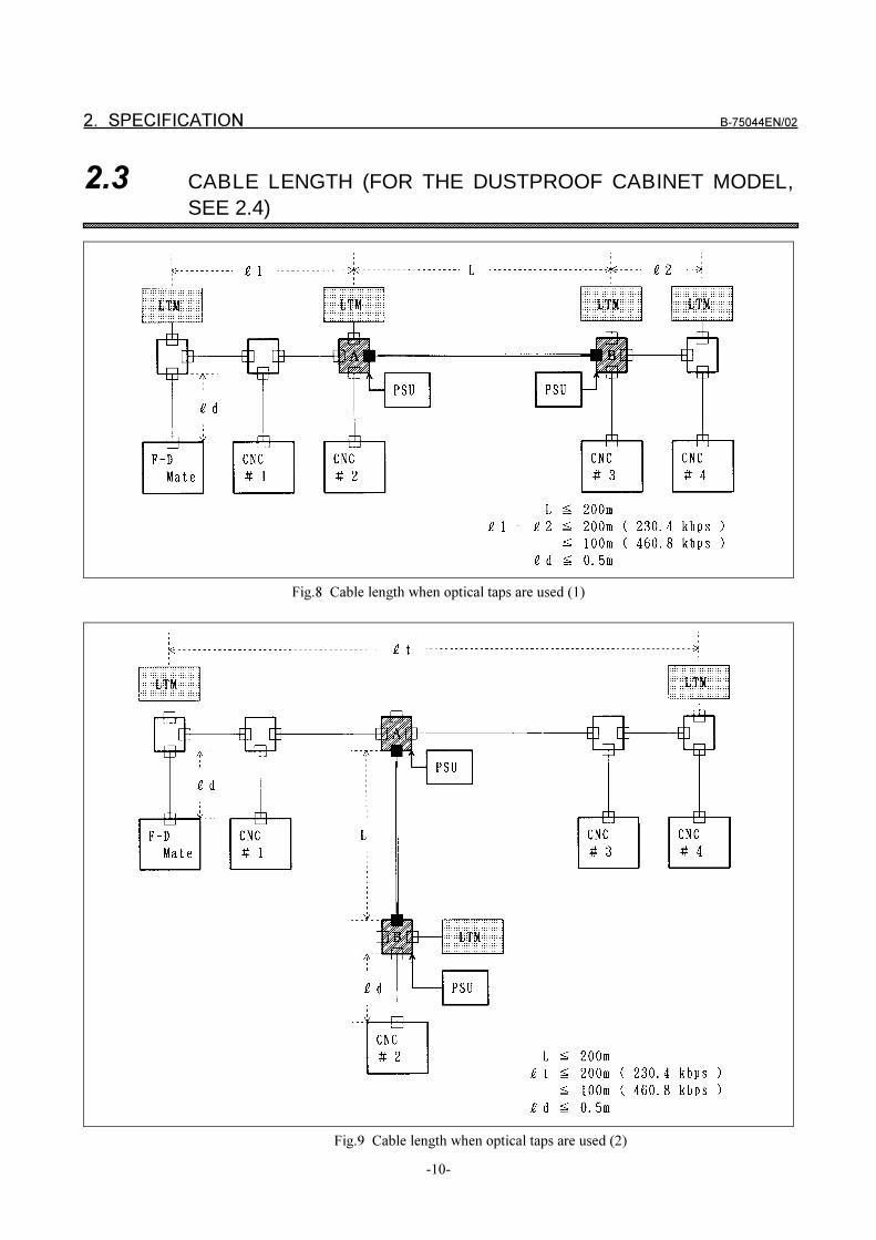
2. SPECIFICATION B-75044EN/02
-10-
2.3 CABLE LENGTH (FOR THE DUSTPROOF CABINET MODEL,
SEE 2.4)
Fig.8 Cable length when optical taps are used (1)
Fig.9 Cable length when optical taps are used (2)
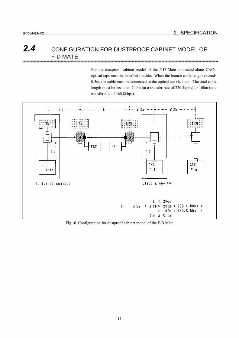
B-75044EN/02 2. SPECIFICATION
-11-
2.4 CONFIGURATION FOR DUSTPROOF CABINET MODEL OF
F-D MATE
For the dustproof cabinet model of the F-D Mate and stand-alone CNCs,
optical taps must be installed outside. When the branch cable length exceeds
0.5m, the cable must be connected to the optical tap via a tap. The total cable
length must be less than 200m (at a transfer rate of 230.4kpbs) or 100m (at a
transfer rate of 460.8kbps).
Fig.10 Configuration for dustproof cabinet model of the F-D Mate
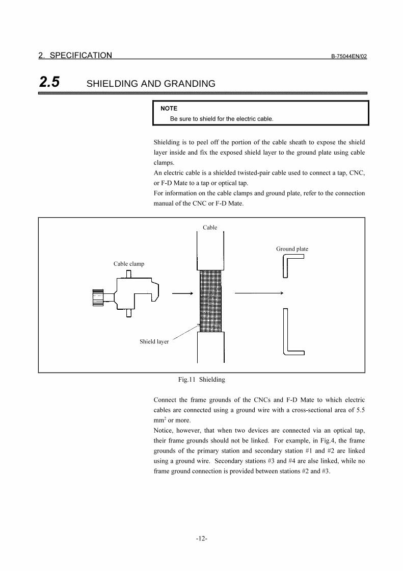
2. SPECIFICATION B-75044EN/02
-12-
2.5 SHIELDING AND GRANDING
NOTE
Be sure to shield for the electric cable.
Shielding is to peel off the portion of the cable sheath to expose the shield
layer inside and fix the exposed shield layer to the ground plate using cable
clamps.
An electric cable is a shielded twisted-pair cable used to connect a tap, CNC,
or F-D Mate to a tap or optical tap.
For information on the cable clamps and ground plate, refer to the connection
manual of the CNC or F-D Mate.
Fig.11 Shielding
Connect the frame grounds of the CNCs and F-D Mate to which electric
cables are connected using a ground wire with a cross-sectional area of 5.5
mm2 or more.
Notice, however, that when two devices are connected via an optical tap,
their frame grounds should not be linked. For example, in Fig.4, the frame
grounds of the primary station and secondary station #1 and #2 are linked
using a ground wire. Secondary stations #3 and #4 are alse linked, while no
frame ground connection is provided between stations #2 and #3.
Cable
Ground plate
Cable clamp
Shield layer
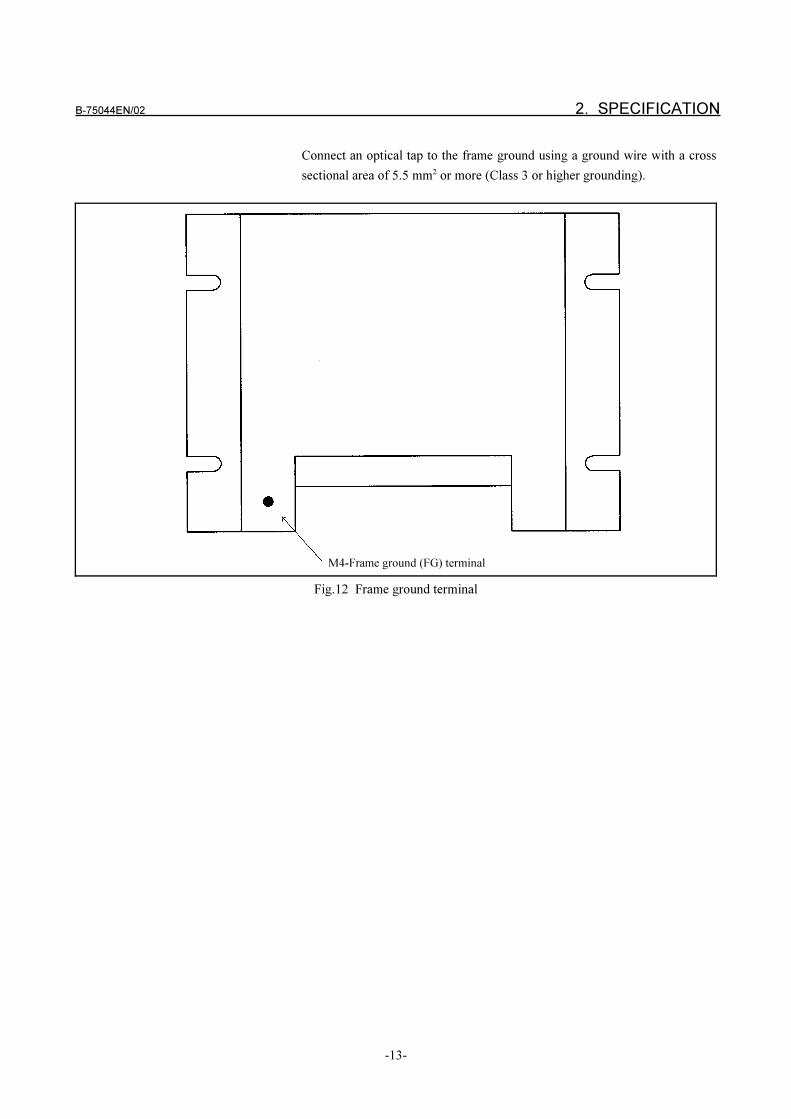
B-75044EN/02 2. SPECIFICATION
-13-
Connect an optical tap to the frame ground using a ground wire with a cross
sectional area of 5.5 mm2 or more (Class 3 or higher grounding).
Fig.12 Frame ground terminal
M4-Frame ground (FG) terminal
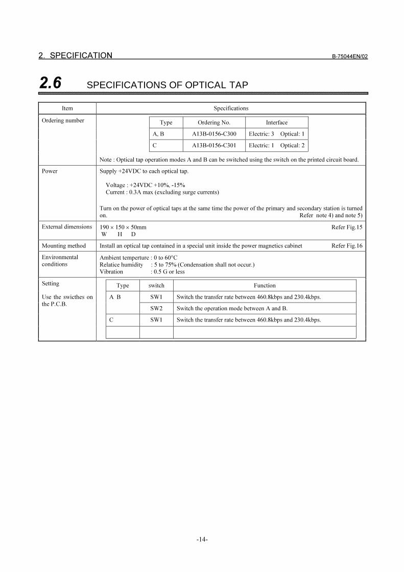
2. SPECIFICATION B-75044EN/02
-14-
2.6 SPECIFICATIONS OF OPTICAL TAP
Item Specifications
Ordering number Type Ordering No. Interface
A, B A13B-0156-C300 Electric: 3 Optical: 1
C A13B-0156-C301 Electric: 1 Optical: 2
Note : Optical tap operation modes A and B can be switched using the switch on the printed circuit board.
Power Supply +24VDC to each optical tap.
Voltage : +24VDC +10%, -15%
Current : 0.3A max (excluding surge currents)
Turn on the power of optical taps at the same time the power of the primary and secondary station is turned
on. Refer note 4) and note 5)
External dimensions 190 � 150 � 50mm Refer Fig.15
W H D
Mounting method Install an optical tap contained in a special unit inside the power magnetics cabinet Refer Fig.16
Environmental
conditionsAmbient temperture : 0 to 60�C
Relatice humidity : 5 to 75% (Condensation shall not occur.)
Vibration : 0.5 G or less
Setting Type switch Function
A B SW1 Switch the transfer rate between 460.8kbps and 230.4kbps.Use the swicthes on
the P.C.B.SW2 Switch the operation mode between A and B.
C SW1 Switch the transfer rate between 460.8kbps and 230.4kbps.
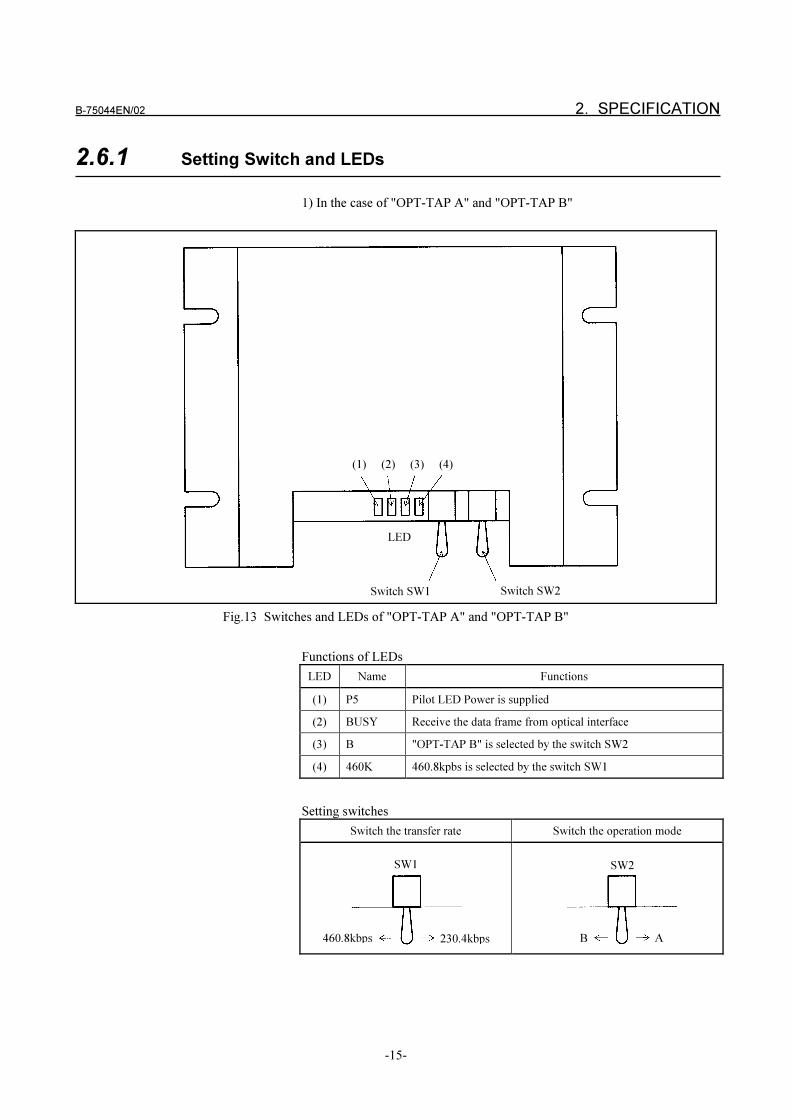
B-75044EN/02 2. SPECIFICATION
-15-
2.6.1 Setting Switch and LEDs
1) In the case of "OPT-TAP A" and "OPT-TAP B"
Fig.13 Switches and LEDs of "OPT-TAP A" and "OPT-TAP B"
Functions of LEDs
LED Name Functions
(1) P5 Pilot LED Power is supplied
(2) BUSY Receive the data frame from optical interface
(3) B "OPT-TAP B" is selected by the switch SW2
(4) 460K 460.8kpbs is selected by the switch SW1
Setting switches
Switch the transfer rate Switch the operation mode
(1) (2) (3) (4)
LED
Switch SW1 Switch SW2
SW1
460.8kbps 230.4kbps
SW2
B A
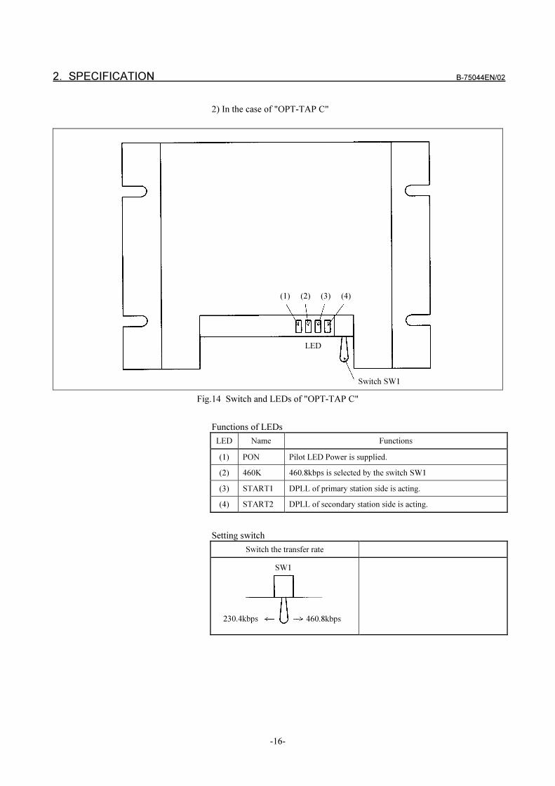
2. SPECIFICATION B-75044EN/02
-16-
2) In the case of "OPT-TAP C"
Fig.14 Switch and LEDs of "OPT-TAP C"
Functions of LEDs
LED Name Functions
(1) PON Pilot LED Power is supplied.
(2) 460K 460.8kbps is selected by the switch SW1
(3) START1 DPLL of primary station side is acting.
(4) START2 DPLL of secondary station side is acting.
Setting switch
Switch the transfer rate
(1) (2) (3) (4)
LED
Switch SW1
SW1
230.4kbps 460.8kbps
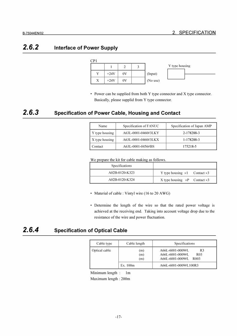
B-75044EN/02 2. SPECIFICATION
-17-
2.6.2 Interface of Power Supply
CP1
1 2 3
Y +24V 0V (Input)
X +24V 0V (No use)
• Power can be supplied from both Y type connector and X type connector.
Basically, please supplid from Y type connector.
2.6.3 Specification of Power Cable, Housing and Contact
Name Specification of FANUC Specification of Japan AMP
Y type housing A63L-0001-0460#3LKY 2-178288-3
X type housing A63L-0001-0460#3LKX 1-178288-3
Contact A63L-0001-0456#BS…. 175218-5…
We prepare the kit for cable making as follows.
Specifications
A02B-0120-K323 Y type housing �1 Contact �3
A02B-0120-K324 X type housing �P Contact �3
• Material of cable : Vintyl wire (16 to 20 AWG)
• Determine the length of the wire so that the rated power voltage is
achieved at the receiving end. Taking into account voltage drop due to the
resistance of the wire and power fluctuation.
2.6.4 Specification of Optical Cable
Cable type Cable length Specifications
Optical cable (m)
(m)
(m)
A66L-6001-0009#L R3
A66L-6001-0009#L R03
A66L-6001-0009#L R003
Ex. 100m A66L-6001-0009#L100R3
Minimum length : 1m
Maximum length : 200m
Y type housing
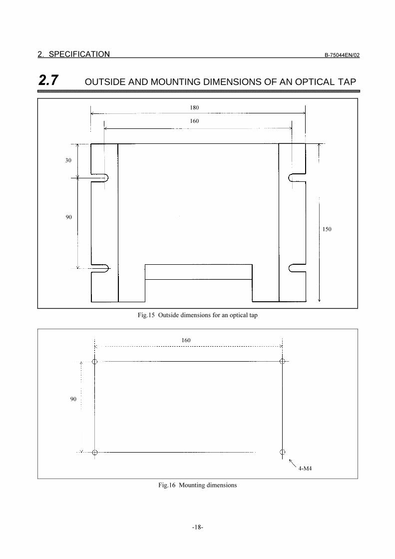
2. SPECIFICATION B-75044EN/02
-18-
2.7 OUTSIDE AND MOUNTING DIMENSIONS OF AN OPTICAL TAP
Fig.15 Outside dimensions for an optical tap
Fig.16 Mounting dimensions
180
160
150
30
90
160
90
4-M4
B-75044EN/02INDEX
A
About FA SYSTEM for PC 1
About Log Message 167
About Log Viewer 171
ABOUT NC PROGRAM FORMAT 13
About Sample Program 76
About Starting Applications You Have Developed 75
About the Development Language of
the Application Program 74
About The NC PROGRAM MANAGEMENT
Window 49
Adding Internet Service 30
B
Browsing, Editing and Creating New Files 58
C
Canceling Computer Start Download
< F_DownloadCancel > 157
Canceling Computer Start Upload
< F_UploadCancel > 158
Communication Settings for Machine 38
Computer Start DNC Operation < F_Dnc... > 153
Conditions for using the DNC1 driver 239
Confirmation of Communication < F_IsOpen > 99
Confirmation of DNC1 Connection
< F_ConfirmDnc1 > 124
Copying, Moving, Deleting and Renaming Files 56
Cycle Start < F_Start > 115
D
Deleting NC Program in NC < F_Delete > 117
Details of List File Extended Transfer Function 21
Details of List File Separate Transfer Function 20
Details of Subprogram Extended Transfer Function 17
Details of Subprogram Separate Transfer Function 16
DIAGNOSIS AND OTHER SERVICES 159
DNC1 23, 26
DNC1 BOARD, OPTICAL FIBER CABLE AND
OPTICAL CONNECTOR SPECIFICATIONS 276
DNC1, DNC2 200
DNC1/ETHERNET 213
Dnc1HardTest 246
Dnc1LogViewer 268
Dnc1Test 251
DNC2, Reader/Puncher 27
Download Settings for Machine 43
Downloading NC Program requested by Computer
< F_Download... > 107
E
EDIT LIST FILE SCREEN OPERATIONS 180
Editing List Files 183
End of Communication Process
< F_TerminateCommunication > * 97
End of FA LIBRARY < F_End > 162
End of Receiving Notice Message
< F_StopNotice > 104
Error Code 214
Establishing DNC1 Connection
< F_EstablishDnc1 > 123
External Reset < F_Reset > 114
F
FA LIBRARY 71
For Setting FA SYSTEM for PC 31
Freeing Descriptor ID < F_FreeID > 160
G
General Settings for Machine 36
Getting Descriptor ID of Notice Message
< F_GetNoticeID > 104
Getting Error Code < F_GetLastError > 161
Getting Information about Machine
< F_GetMachineInfo > 106
Getting List of Communicating Machines
< F_GetOpenMachineNumber > 102
Getting List of Registered Machine Numbers
<F_GetAllMachineNumber > 100
INDEX B-75044EN/02
i-2
Getting Number of Data < F_GetCount > 159
Getting Result of Asynchronous Treatment
< F_Response > 161
Getting the Notice Message of the File Transfer
< F_CopyNoticeFileTransfer > 105
H
How to Read the Library Function 73
I
Initialization Processing < F_Begin > 159
L
LIST FILE MANAGEMENT 179
List File Monitor Operations 190
LIST FILE MONITOR SCREEN OPERATIONS 189
LIST FILE TRANSFER FUNCTION 18
List File Transfer Monitor and Control Functions 21
LOG LIBRARY 163
Log Viewer 167
Log Server 177
M
Machine Information Settings 35
MAINTENANCE INFORMATION 280
MAINTENANCE INFORMATION OF
DNC1BOARD 273
Moving Offset Location of Data < F_Seek > 160
N
NC PROGRAM MANAGEMENT 47
O
Observation of FA SYSTEM for PC 166
P
PRECAUTIONS WHEN HANDLING RELATED
PARTS 277
R
Reader/Puncher 205
Reading Alarm Information < F_ReadAlarm > 126
Reading Custom Macro Variable
< F_ReadCustomMacroVariable > 135
Reading List of NC Program in NC
< F_AllFileDirectory > 120
Reading NC Identification < F_Identify > 119
Reading NC Parameters < F_ReadParameter > 148
Reading PMC Data < F_ReadPMCData > 144
Reading Tool Life Management Information
< F_ReadToolLife > 140
Reading Tool Offset < F_ReadToolOffset > 128
Relation between FA SYSTEM for PC and
Protocols 5
REQUEST SERVICE 107
S
Sample of NC Parameter Settings 195
Sample Operation for NC 199
Saving and Restoring Settings 45
Selecting NC Program in NC < F_Select > 116
Selecting the NC Program on the PC 66
Service Type 72
Setting FA SYSTEM for PC 29
Setting log creation ON/OFF 177
Setting Options 69
Setting up DNC1 Driver 241
Setting up TCP/IP 29
Setting up the DNC1 Board 240
Setup 23
Start of Communication < F_Open > 98
Start of Communication Process
< F_CreateCommunication > * 96
Start of Receiving Notice Message
< F_StartNotice > 103
Starting and Stopping the Communication Process 34
Starting LogServer < F_InvokeLogServer > 165
Stop of Communication < F_Close > 99
Structure of Edit List File Screen 180
B-75044EN/02 INDEX
i-3
Structure of List File Monitor Screen 189
SUBPROGRAM TRANSFER FUNCTION 14
System Configuration 35
System Requirements 24
SYSTEM REQUIREMENTS FOR DNC1
BOARD 237
System Service 95
T
Terminating LogServer
< F_TerminateLogServer > 165
The Contents of Log File 170
The Contents of Transmission Log File 169
Transmitting an NC Program 61
Transmitting by Operating NC PROGRAM
MANAGEMENT 7
Transmitting by Operating NC Side 10
Transmitting by Using FA LIBRARY 8
TRANSMITTING NC PROGRAM 7
U
Upload Settings for Machine 44
Uploading NC Program Requested by Computer
< F_Upload... > 111
Using Log Viewer 172
Using NC PROGRAM MANAGEMENT 49
W
Work with the Directory List 54
Work with the File List 51
Writing Custom Macro Variable
< F_WriteCustomMacroVariable > 138
Writing NC Parameters < F_WriteParameter > 151
Writing PMC Data< F_WritePMCData > 146
Writing Tool Offset < F_WriteToolOffset > 132
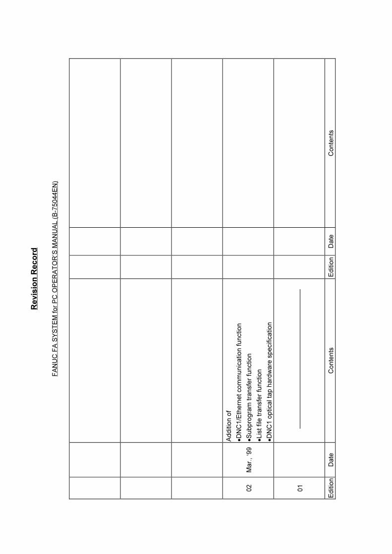
Re
vis
ion
Re
co
rd
FA
NU
C F
A S
YS
TE
M f
or
PC
OP
ER
AT
OR
’S M
AN
UA
L (
B-7
5044E
N)
02
Mar.
, ‘9
9
Additio
n o
f
�D
NC
1/E
thern
et com
munic
ation f
unction
�S
ubpro
gra
m tra
nsfe
r fu
nction
�Lis
t file
tra
nsfe
r fu
nction
�D
NC
1 o
ptical ta
p h
ard
ware
specific
ation
01
Editio
nD
ate
Conte
nts
Editio
nD
ate
Conte
nts


![The Value 1 Problem for Probabilistic Automata - LIAFAA characterization 20 fA∗ is the space of prostochastic words. A∗ = fA∗[0] ( fA∗[1] ( fA∗[2] ( ··· ( fA∗. Lemma](https://img.pdfslide.us/doc/110x75/60bb28a9a2770504c97cb50e/the-value-1-problem-for-probabilistic-automata-liafa-a-characterization-20-faa.jpg)


![FA Equipment for Beginners(HMIs) THA.ppt [互換モード]...HMI tq:fu GT Simulator3 Mitsubishi Electric PC HMI RS-232C PC USB HMI PLC 000 HMI PLC FA Equipment for Beginners(HMIs)](https://img.pdfslide.us/doc/110x75/5e459b24cf716854423e8a33/fa-equipment-for-beginnershmis-thappt-fff-hmi-tqfu-gt-simulator3.jpg)