Embed Size (px)
Citation preview
3 2 18 7 6 5 4
Rectifier /Regulatorp/n: 82501R
25/08/05Piaggio Ltd. With IMMOBILISER
B 125 / 200 ignition / charging
Red
White / Black
Yellow
IgnitionPick up
CDI / Immobiliser
IgnitionSwitch
HT Coil
White
Purple
Red / Black
Black
White
CoolingFan Fan
Switch
Red / Black
Green
White / Green or Light Blue
White
Red / Black
Lt. Blue
White /Green
G
Choke Unit White
White /OrangeWhite
Lt. Blue
Black / BlueIndicatorSwitch
Yellow / Blue
Red / Blue
Red / Black
Green
Orange
Emergency Stop
Green / Blue
OFF
1
2
Seat Lock Seat ReleasePush Button
Blue
White / BlueWhite
Blue
Green
Ignition Relay
4 amp
BATTERY12v
10ah
+
CR 9EB
Side StandSwitch
ImmobiliserLED
StandWarning
Blue / Black
CDI CONNECTIONS1. BLUE / BLACK - INDICATOR SWITCH SUPPLY2. GREEN - INPUT FROM IGNITION PICK UP3. PURPLE - TO HT COIL4. RED / BLACK - 12v PERMANENT LIVE5. WHITE / GREEN - SUPPLY FROM IGNITION SWITCH6. YELLOW / BLUE - IMMOBILISER LED7. WHITE / BLACK - CHOKE CONTROL8. BLACK - EARTH
STOP
RUN
Down
UP
2-1
15 4
Blu
e
Red
/ B
lack
Red
/ B
lue
15 15
White / Black
Yellow / Blue
White / Green
Red / Black
antenna

2-2
B 125 / 200 NOTES
The notes should be used in conjunction with Service Station Manual 594845 andthe notes “B 125 ignition / charging” and “B 125 Fuse Explanation”
1. Seat has electric release. Only works when ignition switch is in the “off”position.If seat lock fails to operate:
Check fuse “7” in rear fuse box. 4 amp red wire in & blue wire out. Check for power on Blue wire at ignition switch Check for power on White / Blue wire at ignition switch with ignition “off”. Check the push button, Blue / Black should earth when button is pressed.
Seat lock, power socket and under seat light are all controlled by the samefuse.
2. Wires from The engine. Three Yellow wires: Three phases of generator, all feed directly to the
rectifier / regulator. Green wire: Ignition pick up. Goes to ECU unit. Brown wire: From oil pressure switch, goes to indicator light on instrument
panel.
3. Immobiliser is like other Leader engines. There are separate notes to explainthe immobiliser system.
4. Fuel system. (similar to the DNA 125 / 180 four strokes) Fuel is pumped from the tank and supplied to the carburettor under
pressure. Fuel pump is on the bottom of the tank and is driven by manifold vacuum. The feed pipe from pump to carburettor has a non-return valve and an
inline filter. 200cc engine may (early vehicles) have a vacuum pipe that branches off
to operate an over run valve in the carburettor. Carburettor icing is controlled by a warm water feed from the cooling
system. Choke is the automatic (wax pellet) type used on all our automatics.
Remember that these units default to being “ON” and are turned offelectrically. They are more likely to cause running rich when hot than coldstarting problems.
5. Spark Plugs.Please note that the correct spark plugs are:125cc :- NGK CR8 EB p.n. 828866200cc :- Champion RG6 YC p.n. 828708 (or NGK CR7EB)

08/05/2003Piaggio Ltd. Piaggio Ltd.
B 125 FUSE EXPLANATION
FRONT FUSE BOX
2 4 amp
4 4 amp
3 7.5amp
1 4 ampWHITE
12v DC fromignition switch
GREYFrom light
switchYELLOW
Anologue, Inst. & side lights
RED / GREYHorn, Headlight flash
WHITE / REDBrake lights, start inhibit
WHITE / ORANGEEngine start, run, warning lights
REAR FUSE BOX
7
15a
5
4a
6
10a
8
15a
RED12v DC from battery
RED / BLUEDigital Panel, LED, Radio
RED / BLACKGeneral
YELLOWHeadlight via relay
BLUEUnder seat, Light, Socket, Lock
2-3

Rectifier /Regulatorp/n: 82501R
13/08/2003Piaggio Ltd. DNA 125 / 180
DNA Leader engine ignition / charging
GALTERNATORSTATOR
ToIndicatorswitch
Headlightvia relay
Red
Green
Green
White / Black
Yellow
IgnitionPick up
ECU
IgnitionSwitch
Blue /Black
15amp
Blue / Red
Green / Yellow
White/ Pink
Red
Power toLights, horninstruments
Black
3 2 18 7 6 5 4
BATTERY12v
12ah
+
Choke Unit
Red
Lt. Blue / Green
Yellow / RedRedWhite
Connector for Alarm
Orange
Orange
Yellow
7.5amp
7.5amp
FanSwitch
GreenCoolingFan
HT Coil
NGKCR 8EB
White / Black
Blue / Red
Blue / Red
STATOR: ANY YELLOW TO ANY YELLOW = 0.7 - 0.9 ohm. YELLOW TO EARTH = NO CONTINUITY GREEN TO BLACK (EARTH) = 105 - 124 ohm
REGULATOR: VOLTAGE ACROSS A FULLY CHARGED BATTERY, LIGHTS OFF, HIGH REVS = 14 - 15.2 V.CHARGING: AMMETER IN RED WIRE = > 8 AMPS WITH LIGHTS ON AND HIGH REVS.HT COIL: PRIMARY = 0.4 - 0.5 OHM. SECONDARY = 3K + 300 OHM.
OFF
ON
STOP
RUN
2-4

08/05/2003Piaggio Ltd. Refer to Service Station Manual594329 (02/01) page 4-23>
DNA 125 / 180 Switch Wiring
FEED FROM LIGHT SWITCH. WHEN LIGHTS ARE TURNED ON
SUPPLY TO REAR LIGHTS AND FRONT PILOT LIGHT
MAIN SUPPLY TO IGNITION SYSTEM, LIGHTS ETC.
MAIN FEED FROM BATTERY
OFF
PARK
LOCK
ON
3 4 6521
IGNITION SWITCHITEM 6 ON WIRING DIAGRAM
BROWN
GREEN
BLACK
RED
YELLOW - BLACK
WHITE
ORANGE
OFF
LEFT
RIGHT
LOW
HIGH
FLASH
0
PUSH
PINKBLUE - BLACK
WHITE - BLUEWHITE
PURPLEBROWN
YELLOW - BLACKGREY - BLACK
BLACK
LEFT HANDSWITCHES
ITEM 8ON WIRING DIAGRAM
HORNINDICATORS MAIN / DIP
0
RUN
0
PUSH
OFF
SIDE
ALL
EMERGENCYSTOPSTARTLIGHTS
WHITEYELLOW - RED
GREEN - BLACKWHITE - BLACK
ORANGEBROWN
YELLOW
RIGHT HANDSWITCHES
ITEM 9ON WIRING DIAGRAM
2-5
Rectifier /Regulatorp/n: 82501R
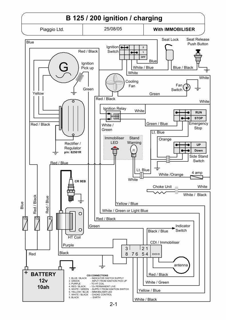
30/09/2005Piaggio Ltd. With IMMOBILISER
ET4 Leader / LX 125 ignition / charging
GALTERNATORSTATOR
ToIndicatorswitch
Headlightvia relay
Red
Green
Green
White /Black
Red / Blue
RG4HCCR 9E
Carb. Heater
Choke Unit
Yellow
IgnitionPick up
ECU / Immobiliser
IgnitionSwitch
HT Coil
Blue /Black
15amp
Orange
Orange
White
Red /Blue
Purple
Grey
Red / Blue
Powerto
services
Red / Blue
Black
antennaYellow
LED oninstrument
pannel
Diagnosticsocket
6 1
8 3
4 5
7 2 GREEN
WHITE / BLACKORANGE
RED / BLUE
PURPLEBLACK
BLUE / BLACK
YELLOW
Layout of pinsin the ECU / immobiliser
Orange
7.5amp
BATTERY12v9ah
+
3 2 18 7 6 5 4
TESTS.STATOR: ANY YELLOW TO ANY YELLOW = 0.7 - 0.9 ohm.
YELLOW TO EARTH = NO CONTINUITY GREEN TO BLACK (EARTH) = 105 - 124 ohm
REGULATOR: VOLTAGE ACROSS A FULLY CHARGED BATTERY, LIGHTS OFF, HIGH REVS = 14 - 15.2 V.
CHARGING: AMMETER IN RED WIRE = > 8 AMPS WITH LIGHTS ON AND HIGH REVS.
HT COIL: PRIMARY = 0.4 - 0.5 OHM. SECONDARY = 3K + 300 OHM.
OFF
ON
2-6
Rectifier /Regulatorp/n: 82501R
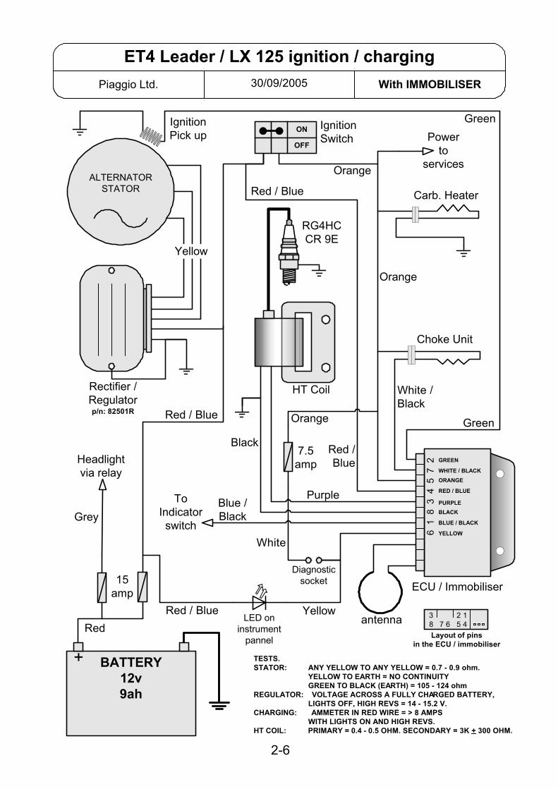
13/03/02Piaggio Ltd. With IMMOBILISER
Hexagon GTX 125 ignition / charging
GALTERNATORSTATOR
ToIndicatorswitch
Red
Green
Green
White/ Black
White
Yellow
IgnitionPick up
ECU / Immobiliser
IgnitionSwitch
HT Coil
Blue / Black15amp
Orange
Orange
Red
Purple
Red
Red
Black
antenna
Yellow
Red / Blue
LED oninstrumentpannel
Layout of pinsin the ECU / immobiliser
Yellow / Blue
BATTERY12v
12ah
+
Orange
RG4HCCR 9EB
CoolingFan
FanSwitch
RedGreen
Choke Unit
Lt. Blue
Orange
5amp
5amp 6
1 8
3 4
5 7
2 GREEN
WHITE / BLACKLt. BLUE
RED
PURPLEBLACK
BLUE / BLACK
YELLOW
Diagnosticsocket
3 2 18 7 6 5 4
TESTS.STATOR: ANY YELLOW TO ANY YELLOW = 0.7 - 0.9 ohm.
YELLOW TO EARTH = NO CONTINUITY GREEN TO BLACK (EARTH) = 105 - 124 ohm
REGULATOR: VOLTAGE ACROSS A FULLY CHARGED BATTERY, LIGHTS OFF, HIGH REVS = 14 - 15.2 V.
CHARGING: AMMETER IN RED WIRE = > 8 AMPS WITH LIGHTS ON AND HIGH REVS.
HT COIL: PRIMARY = 0.4 - 0.5 OHM. SECONDARY = 3K + 300 OHM.
OFF
ON
STOP
RUN
2-7

antenna
Rectifier /Regulatorp/n: 82501R
19/07/02Piaggio Ltd. With IMMOBILISER
Runner VX / VXR ignition / charging
GALTERNATORSTATOR
ToIndicatorswitch
Headlightvia relay
Red
Green
Green
White /Black
Red / Blue
Choke Unit
Yellow
IgnitionPick up
ECU / Immobiliser
IgnitionSwitch
HT Coil
Blue / Black
15amp
Red / Blue
Orange
Red
Purple
Grey/ Red
Red
Power toservices
Red
Black
Yellow
Red / Blue
NGKCR 8EB
CoolingFanFan
Switch
Red
Green5
amp
6 1
8 3
4 5
7 2 GREEN
WHITE / BLACKRED / BLUE
RED
PURPLEBLACK
BLUE / BLACK
YELLOW
Diagnosticsocket
Red
LED oninstrumentpannel
Yellow / Red
Layout of pinsin the ECU / immobiliser
3 2 18 7 6 5 4
TESTS.STATOR: ANY YELLOW TO ANY YELLOW = 0.7 - 0.9 ohm.
YELLOW TO EARTH = NO CONTINUITY GREEN TO BLACK (EARTH) = 105 - 124 ohm
REGULATOR: VOLTAGE ACROSS A FULLY CHARGED BATTERY, LIGHTS OFF, HIGH REVS = 14 - 15.2 V.
CHARGING: AMMETER IN RED WIRE = > 8 AMPS WITH LIGHTS ON AND HIGH REVS.
HT COIL: PRIMARY = 0.4 - 0.5 OHM. SECONDARY = 3K + 300 OHM.
BATTERY12v
10ah
+
OFF
ON
2-8
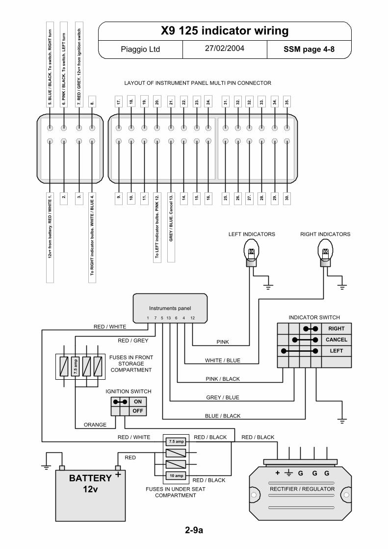
27/02/2004Piaggio Ltd SSM page 4-8
X9 125 indicator wiring
10 amp
7.5 amp
7.5
amp
BATTERY12v
+
Instruments panel
OFF
ON
LEFT
CANCEL
RIGHT
+ G G G
FUSES IN UNDER SEATCOMPARTMENT
RECTIFIER / REGULATOR
INDICATOR SWITCH
LEFT INDICATORS
FUSES IN FRONTSTORAGE
COMPARTMENT
IGNITION SWITCH
RIGHT INDICATORS
RED
RED / BLACK
RED / BLACK
RED / BLACKRED / WHITE
ORANGE
RED / GREY
RED / WHITE
BLUE / BLACK
GREY / BLUE
PINK / BLACK
WHITE / BLUE
PINK
LAYOUT OF INSTRUMENT PANEL MULTI PIN CONNECTOR
1 7 5 13 6 4 12
5. B
LUE
/ BLA
CK
. To
switc
h. R
IGH
T tu
rn
6. P
INK
/ B
LAC
K. T
o sw
itch.
LEF
T tu
rn
7. R
ED /
GR
EY. 1
2v+
from
igni
tion
switc
h
8. 22.
21.
20.
19.
18.
17.
24.
31.
32.
32.
33.
34.
35.
23.
12v+
from
bat
tery
. RED
/ W
HIT
E 1. 2.
3.
To R
IGH
T in
dica
tor b
ulbs
. WH
ITE
/ BLU
E 4. 14
.
GR
EY /
BLU
E. C
ance
l 13.
To L
EFT
indi
cato
r bul
bs. P
INK
12.11
.
10.
9.
16.
25.
26.
27.
28.
29.
30.
15.
2-9a

Rectifier /Regulatorp/n: 82501R
15/10/2004Piaggio Ltd. With IMMOBILISER
X9 125 / 180 & 250 Evo ignition / charging
GALTERNATORSTATOR
Red
Green
Green
White / Black
Yellow
IgnitionPick up
ECU / Immobiliser
IgnitionSwitch
15amp
Orange
Orange
Red / Black
Yellow
Layout of pinsin the ECU / immobiliser
Yellow / Grey
BATTERY12v
12ah
+
CoolingFan
Fan Switch
Red / Black
Green
Choke Unit
EmergencyStop
Lt. Blue
Orange
5amp
Diagnosticsocket
2 GREEN
7 WHITE / BLACK
5 Lt. BLUE
4 RED / BLACK
3 PURPLE8 BLACK
6 YELLOW
Red / Black
Yellow / BlueYellow / Green
Grey/ Black
Lt. Blue
TESTS.STATOR: ANY YELLOW TO ANY YELLOW = 0.7 - 0.9 ohm.
YELLOW TO EARTH = NO CONTINUITY GREEN TO BLACK (EARTH) = 105 - 124 ohm
REGULATOR: VOLTAGE ACROSS A FULLY CHARGED BATTERY, LIGHTS OFF, HIGH REVS = 14 - 15.2 V.
CHARGING: AMMETER IN RED WIRE = > 8 AMPS WITH LIGHTS ON AND HIGH REVS.
HT COIL: PRIMARY = 0.4 - 0.5 OHM. SECONDARY = 3K + 300 OHM.
3 2 18 7 6 5 4
RG4HCCR 9EB
HT Coil
Purple
Black
SideStandSwitch
Red / White
STOP
RUN
STOP
RUN
UP
DOWN
2-9
ImmobiliserLED
StandWarning
Power toServices
antenna NOTE.Indicators are powered bythe digital instrument panel.

Rectifier /Regulatorp/n: 82501R
13/08/2003Piaggio Ltd. NO Immobiliser
ZIP 125 Leader engine ignition / charging
GALTERNATORSTATOR
ToIndicatorswitch
Red
Green
Green
White /Black
Choke Unit
Yellow
IgnitionPick up Ignition
Switch
Blue / Black15amp
Orange
Orange
Purple
Red / Blue
Powerto
services
Black
ECU CONNECTIONS1. BLUE / BLACK - INDICATOR SWITCH SUPPLY2. GREEN - INPUT FROM IGNITION PICK UP3. PURPLE - TO HT COIL4.5. ORANGE - SUPPLY FROM IGNITION SWITCH6.7. WHITE / BLACK - CHOKE CONTROL8. BLACK - EARTH
TESTS.Yellow - Yellow. Charging coils. 0.7 - 0.9 ohmYellow - Earth. No continuityGreen - Earth. Ignition pick up coil. 105 - 124 ohm.Purple - Earth. Coil primary winding. 0.4 - 0.5 ohmHT - Earth. Coil secondary winding. 3000 ohm
LOCK
OFF
ON
Carb. Heater
Layout of pinsin the ECU
3 2 18 7 6 5 4
ECU
6 1
8 3
4 5
7 2 GREEN
WHITE / BLACKORANGE
PURPLEBLACK
BLUE / BLACK
RG6YCCR 7EB
HT Coil
BATTERY12v9ah
+
2-10

2-111 of 2
Piaggio Ltd February 2004
LEADER ENGINEIgnition, charging & immobiliser
Use these notes in conjunction with the SERVICE STATION MANUAL
The electrical system on the new Leader engine is very different to previous two stroke andfour stroke Piaggio engines. The ignition, charging & immobiliser circuits do not function inthe same way and do not share common components with previous versions.
Ignition is now using the battery circuit. Everything shares one common supply. Alternator has three phase (all yellow wires) and ignition pick up coil (green wire) outputs
only. Rectifier / Regulator is very simple. Three phase (yellow) inputs and one output. ECU unit has become more complicated. The one unit is responsible for: ignition,
immobiliser, indicators & choke unit. Much of the circuit is the same on ET4 Leader, Fly 125, Super Hexagon GTX 125,
Liberty 125 Leader, B 125, Skipper ST, Runner VX / VXR and DNA 125 / 180, VespaGT 125 / 200 X8 125, X9 125 and Zip 125 but be careful because there are differences.Early Skipper ST did not have an immobiliser, the later version does have it.
IGNITION.When the ignition is turned on power is supplied to the CDI (terminal 5).Ignition pick up is via green wire (terminal 2).Output to the HT coil is via purple wire (terminal 3).The unit is earthed via black wire (terminal 8).
CDI / IMMOBILISERNote the ECU units have different part numbers for different models and engines size.Refer to the diagram for each specific model. The wiring and wire colours may vary.It is important that the correct part number is used as the ignition characteristics vary andalthough the units look the same they are different!
On vehicles with an immobiliser;The wires connected to the unmarked terminals are from the antenna that is mounted aroundthe ignition lock barrel.Check antenna for continuity, unplugged resistance = 7 - 9 Ω.The red or red / blue wire (terminal 4) supplies battery voltage even with ignition off.Yellow wire (terminal 6) is from the LED on the instrument panel. If the system isprogrammed and working correctly the LED should be flashing steadily with the ignitionturned off to confirm that the immobiliser system is functioning. The immobiliser earths theLED (or not) to make it turn on or off.See pages 3-4 below for more details on using the LED for immobiliser fault finding.
HT COIL. 82597R = Common to most Leader engines. 82582R = Skipper ST & X9 125 Purple to Black - primary winding = 0.4 - 0.5 Ω HT to Black - secondary winding = 3000 ± 300 Ω Plugged in with engine cranking the peak voltage Purple to Earth = 100 vdc

2-112 of 2
Piaggio Ltd February 2004
IGNITION PICK UP COIL. Un plug, check resistance, Green to Black = 105 - 124 Ω Un-plugged with engine cranking the peak voltage Green to Black = 2 vdc
STATOR.Any yellow to yellow should give continuity. Un-plugged, yellow to yellow = 0.7 - 0.9 ΩYellow to earth should not give continuity.
RECTIFIER / REGULATOR. p/n 82501R common to leader engines. Regulated voltage. With a fully charged battery check charging rate by putting volt meter
across the battery terminals. Peak voltage = 14 - 15.2 vdc. Engine at high speed and lightsoff.
Charge current. Connect ammeter to the red wire. Then Start engine. Charge ≥ 10 amp.With the head light turned on.
INDICATORS (Not X9 125).There is no separate indicator relay. The relay function is contained within the ECU unit,Power to the indicator switch is via the blue / black wire (terminal 1).If the indicators fail first check that you are getting voltage at terminal 1 (blue/black)To check the switch and wiring. Unplug the CDI and link red/blue wire to blue/black wire,when the turn switch is operated the appropriate lights should come on. (you will not need theignition to be turned on).
INDICATORS X9 125.X9 has indicators driven by the digital instrument panel.Three wires go to the switch from the panel. The switch earth’s the appropriate wire tooperate the indicators. Output to the indicators comes from the panel. See the explanationdiagram 2-9a.
CHOKE UNIT.The choke is now controlled by the CDI. (not the regulator).Power is supplied to the choke via the main switched wire from the ignition switch to theECU. The unit will not function until the engine is running when the CDI will complete thecircuit to earth (terminal 7).
Un Plugged, resistance across the connections = >< 30 Ω @ 20˚C Plunger extension. Measure how far the plunger protrudes from the body when it is cold,
this should be 12.5 - 13.0 mm. Now connect the choke unit to a 12v battery. The plungershould have extended to 18.5 - 19.0 mm within 5 minutes.
Supply. Orange or Red / Blue to earth = Battery volts with ignition on. Orange or Red / Blue to White/Black = 13-14.5v dc (system volts) with engine running.
CARB. HEATER. Fitted to air-cooled engines.The carburettor heater will start working as soon as the ignition is turned on. Power issupplied via the switched wire that goes to the CDI.Water cooled engines use a warm water connection from the cooling system.
COOLING FAN. On water-cooled engines.The live feed from battery to fan is permanently connected. The switch is in the earth from thefan. So if the fan is faulty it could be the cause of a flat battery.

Piaggio, Gilera & Vespa
Immobilisersystems
The following pages are an explanation of the original fitmentimmobiliser systems fitted to vehicles beginning in the
1990's with the original (pre Leader) Vespa ET4.
Most space is devoted to the system fitted to Leader enginedvehicles because this is by far the most common.
Much of the operation of other systems is the same as the Leadersystem.
Systems covered:
LeaderPre Leader
QuasarMaster
Published January 20061st edition
Piaggio and other after market alarms and immobilisersare not covered here.
Copies of this and other Piaggio technical information can be obtainedfrom the Piaggio UK dealer portal web site
or from Piaggio Ltd.

Immobiliser SystemsINDEX
LEADER
Page 2 - Explanation of operation & Fault codes
Page 3 - I need new keys
Page 4 - I need new locks
Page 5 - I need to fit a new CDI / Immobiliser unit
Page 6 - No Spark - Fault Finding Flow Chart
Page 7 - LED Not Flashing - Power supply problem
Page 8 - Immobiliser functioning correctly
Page 9 - Programming a CDI / Immobiliser
Page 10 - Transponder not detected
Page 11 - Transponder not recognised
PRE LEADER
Page 12 - Explanation of operation & Fault codes
Page 13 - Pre Leader ET4 wiring explanation
QUASAR
Page 14 - Explanation of operation & Fault codes
Page 15 - Notes on fault codes and diagnostic tester
Page 16 - Programming
MASTER
Page 17 - Explanation of operation & Fault codes
Page 18 - Notes on fault codes
Page 19 - Programming

Possible LED Flashing Fault Codes
TUR
N IG
NIT
ION
ON
LED OFF
LED ON
2 x 0.5 sec.
2 x 0.5 sec.0.7 sec.
2 sec.
LED OFF
LED ON
Phase 1 Phase 2 Phase 3
1. Immobiliser not programmed2. Transponder is detected3. Engine will run to 2000rpm
1. Immobiliser is programmed2. Transponder is not detected3. Ignition is not possible
LED OFF
LED ON1. Immobiliser not programmed2. Transponder is not detected3. Engine will run to 2000rpm
2 sec.
3 x 0.5 sec.0.7 sec.
LED OFF
LED ON1. Immobiliser is programmed2. Transponder is not recognised3. Ignition is not possible
0.7 sec.
LED OFF
LED ON1. Immobiliser is programmed2. Transponder is detected3. Engine can run normally
page 2
19/01/2006PAGE 2 EXPLANATION
Leader Immobiliser
1. The immobiliser system fitted to all Piaggio, Gilera & Vespa "Leader" engined vehicles operates in exactly the same way.2. Although the principle is the same the wiring differs on different models.
Refer to the wiring diagram and Service Station Manual for your specific model.3. CDI and immobiliser are combined in one unit.4. The CDI / immobiliser units may look the same but:
They have different characteristics on different models.Ensure you fit the correct unit. Always order by part number .
5. The flashing LED on the instrument panel is the key to understanding how the immobiliser is behaving. The list below shows what the LED can tell you. Note that the LED should flash steadily all the time the ignition is off and the battery is connected. If not, go to PAGE 7 for fault finding information.6. If you have no spark you must first prove that it is not due to the immobiliser.7. Keys should not be on a metal key ring or with other keys. Sometimes this can upset the system.
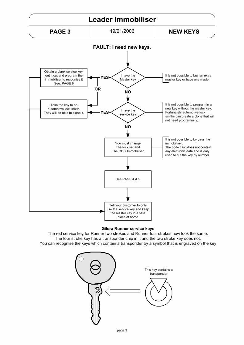
19/01/2006PAGE 3 NEW KEYS
Leader Immobiliser
FAULT: I need new keys.
I have theMaster key
You must changeThe lock set and
The CDI / Immobiliser
I have theservice key
Take the key to anautomotive lock smith.
They will be able to clone it.
Obtain a blank service key,get it cut and program theimmobiliser to recognise it
See: PAGE 9
YES
NO
NO
It is not possible to program in anew key without the master key.Fortunately automotive locksmiths can create a clone that willnot need programming.
It is not possible to buy an extramaster key or have one made.
It is not possible to by pass theimmobiliser.The code card does not containany electronic data and is onlyused to cut the key by number.
See PAGE 4 & 5
Tell your customer to onlyuse the service key and keep
the master key in a safeplace at home
OR
YES
Gilera Runner service keysThe red service key for Runner two strokes and Runner four strokes now look the same.
The four stroke key has a transponder chip in it and the two stroke key does not.You can recognise the keys which contain a transponder by a symbol that is engraved on the key
This key contains atransponder
page 3

page 4
19/01/2006PAGE 4 NEW LOCKS
Leader Immobiliser
FAULT: I need to fit new locks.
Is the originalmaster keyavailable?
1. Fit the new lock set2. Remove the chip from the original master key and fit it to the new master key.3. The immobiliser will not know anything has changed4. Program the the new service key to the immobiliser. See PAGE 9
You must fit a new lock set and a newCDI / Immobiliser unit
It is not possible to bypass theimmobiliser.
See PAGES 4 & 5
The lock set is supplied with one(brown) master key and one service key.
YESNO

19/01/2006PAGE 5 NEW CDI
Leader Immobiliser
FAULT: I need to fit a new CDI / Immobiliser.
I have themaster & service
keyYES
I only havethe master key
I only havethe service key
NO The replacement CDI / immobilisermust be new and unused.
Fit the new CDI and use the servicekey to check the engine starts andruns (only 2000 rpm)
Program the immobiliser.See: PAGE 9
Fit the new CDI and use the masterkey with the chip "out" to check theengine starts and runs(only 2000rpm)
You must replace the lock set
NO YES
Obtain a new service key
Tell your customer to only use theservice key and keep the masterkey in a safe place at home
3 2 18 7 6 5 4
antenna
Output to indicators
Ignition pick up
HT Coil
Earth
Choke unit
LED
Switched Live
Permanent Live
Battery+12v
FUSES
CDI / Immobiliser ConnectionsPlease refer to individual wiring diagrams andService Station Manuals for a full explanationand wiring colours.
1. Choke has a switched live, CDI earths it to complete the circuit and turn it off.
2. LED has a permanent live, CDI earths it to complete the circuit and make it come on.
3. X9 does not use the indicator function. Indicators are driven by the digital panel.
page 5
GREEN
BLACK
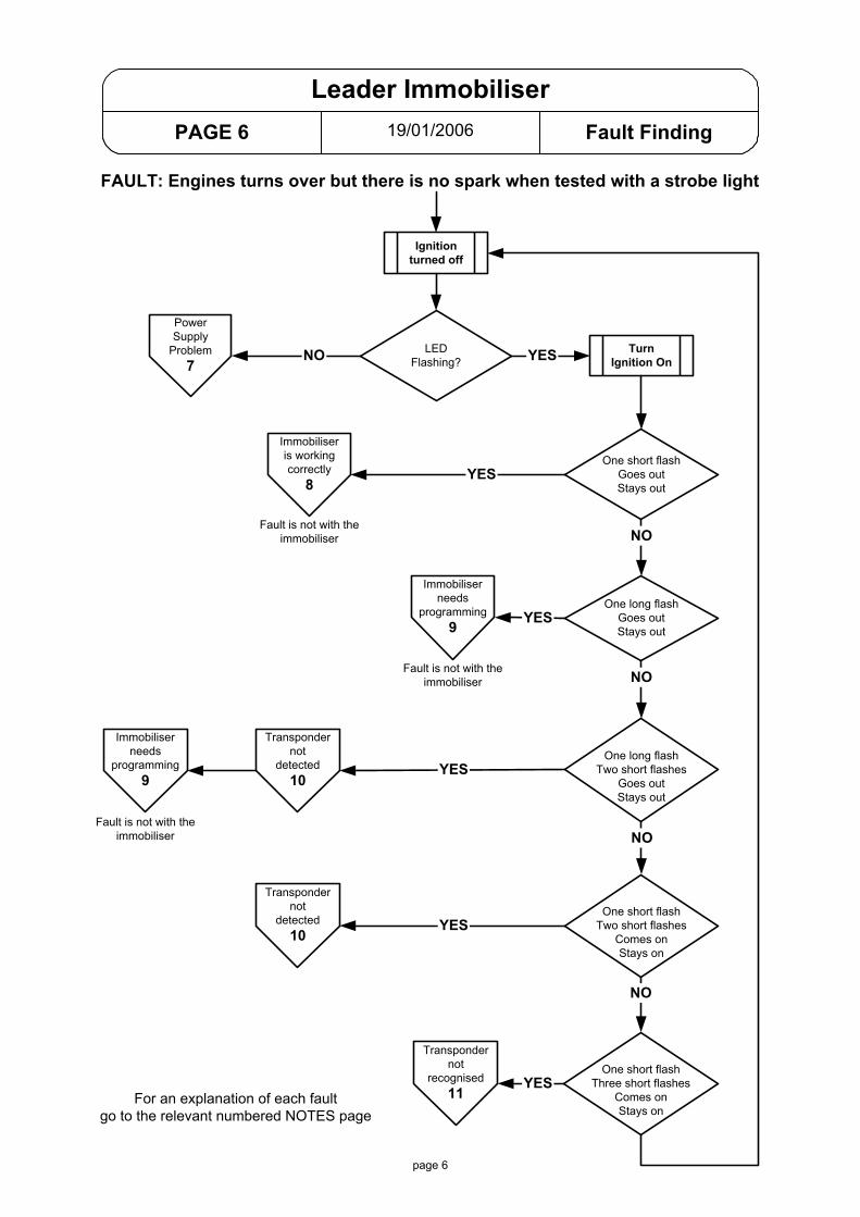
19/01/2006PAGE 6 Fault Finding
Leader Immobiliser
Ignitionturned off
PowerSupply
Problem7
One short flashGoes outStays out
TurnIgnition On
One long flashGoes outStays out
LEDFlashing?
Immobiliseris workingcorrectly
8
Immobiliserneeds
programming9
NO YES
One long flashTwo short flashes
Goes outStays out
One short flashTwo short flashes
Comes onStays on
One short flashThree short flashes
Comes onStays on
Fault is not with theimmobiliser
Immobiliserneeds
programming9
Transpondernot
detected10
Transpondernot
recognised11
Fault is not with theimmobiliser
Fault is not with theimmobiliser
Transpondernot
detected10
FAULT: Engines turns over but there is no spark when tested with a strobe light
For an explanation of each faultgo to the relevant numbered NOTES page
YES
YES
YES
YES
YES
NO
NO
NO
NO
page 6
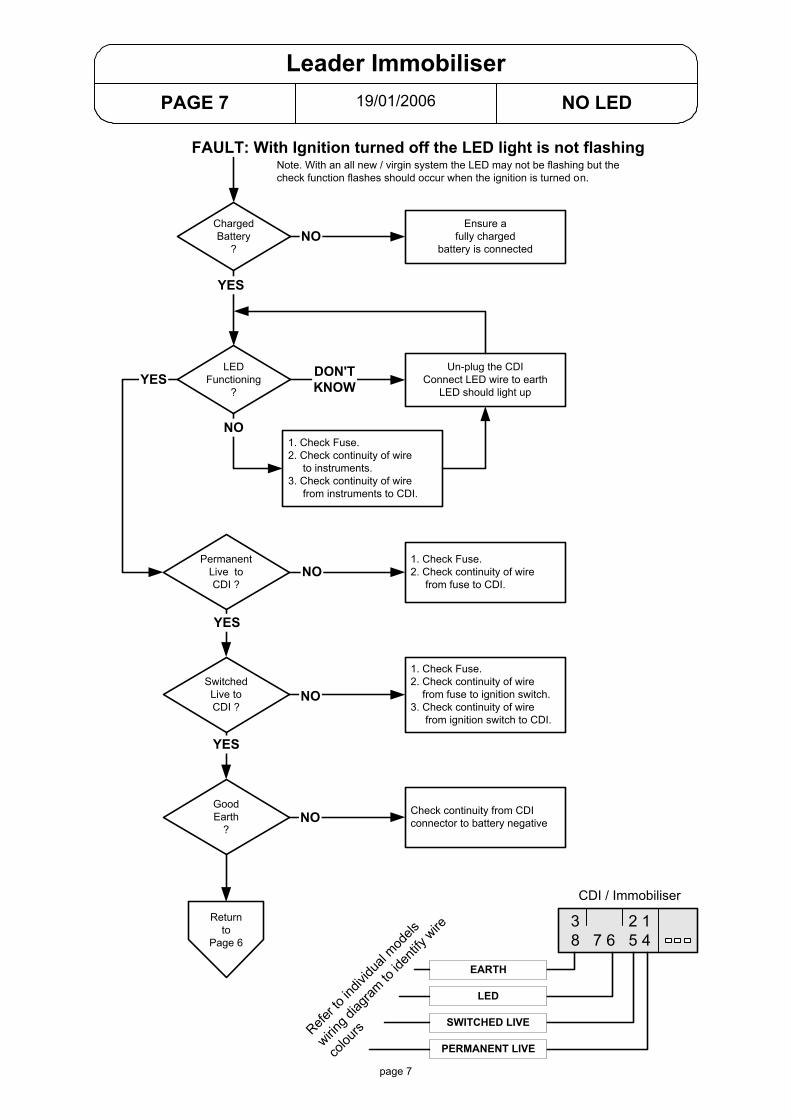
19/01/2006PAGE 7 NO LED
Leader Immobiliser
3 2 18 7 6 5 4
CDI / Immobiliser
PERMANENT LIVE
SWITCHED LIVE
LED
EARTH
FAULT: With Ignition turned off the LED light is not flashing
Refer to
indiv
idual
models
wiring d
iagram
to id
entify
wire
colou
rs
ChargedBattery
?
Ensure afully charged
battery is connected
LEDFunctioning
?
Un-plug the CDIConnect LED wire to earth
LED should light up
PermanentLive toCDI ?
1. Check Fuse.2. Check continuity of wire to instruments.3. Check continuity of wire from instruments to CDI.
YES
NO
DON'TKNOW
NO
YES
SwitchedLive toCDI ?
GoodEarth
?
YES
YES
1. Check Fuse.2. Check continuity of wire from fuse to CDI.
1. Check Fuse.2. Check continuity of wire from fuse to ignition switch.3. Check continuity of wire from ignition switch to CDI.
Check continuity from CDIconnector to battery negative
NO
NO
NO
Returnto
Page 6
page 7
Note. With an all new / virgin system the LED may not be flashing but thecheck function flashes should occur when the ignition is turned on.

19/01/2006PAGE 8 Immobiliser OK
Leader Immobiliser
Ignitionturned off
One short flashGoes outStays out
TurnIgnition On
LEDFlashing?
Immobiliseris workingcorrectly
8
YES
Fault is not with theimmobiliser
FAULT: Engines turns over but there is no spark when tested with a strobe light
YES
We know that the immobiliser is working correctly so the immobiliser system can now be ignoredand normal fault finding can be continued.
1. Test the ignition pick up.Un-plug the CDI. Green wire to earth = 105 - 124 ohms.
2. Test the HT coil (unplugged).Primary: Purple to Earth = 0.4 - 0.5 ohm.Secondary: HT to Earth = 3000 ohms (3k ohm).A 5000 ohms (5K ohm) resistor plug cap should be fitted.
3. Test earth continuity.Un-plug the CDI. Check continuity between black wire and battery negative.
If no fault has been found you should suspect the CDI unit.* Fit a new CDI (not from another bike)* Use the service key (not the brown master key)* Check that the spark is restored. engine should start but it will not rev beyond 2000 rpm.If the fault is cured you must program the CDI unit.GO TO PAGE 9 for programming information.
page 8

19/01/2006PAGE 9 PROGRAMMING
Leader Immobiliser
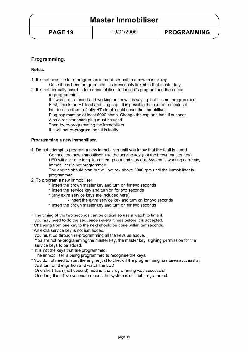
FAULT: I need to program the immobiliser unitNotes.1. It is not possible to re-program an immobiliser unit to a new master key.
Once it has been programmed it is irrevocably linked to that master key.2. It is not normally possible for an immobiliser to loose it's program and then need
re-programming.If it was programmed and working but now it is saying that it is not programmed,First, check the HT lead and plug cap, It is possible that extreme electricalinterference from a faulty HT circuit could upset the immobiliser.Plug cap must be at least 5000 ohms. Change the cap and lead if suspect.A resistor plug must be used on all Leader engines.Then try re-programming the immobiliser.If it will not re-program then it is faulty.
Programming a new immobiliser.1. Do not attempt to program a new immobiliser until you know that the fault is cured.
Attach the new immobiliser, use the service key (not the brown master key)LED will give one long flash then go out and stay out. System is working correctly,Immobiliser is not programmedThe engine should start but will not rev above 2000 rpm until the immobiliser isprogrammed.
2. To program a new immobiliser* Insert the brown master key and turn on for two seconds* Insert the service key and turn on for two seconds* (extra service keys are included here)
- Insert the extra service key and turn on for two seconds* Insert the brown master key and turn on for two seconds
* The timing of the two seconds can be critical so use a watch to time it, you may need to do the sequence several times before it is accepted.* Changing from one key to the next should be done within ten seconds.* An extra service key is not just added, you must go through re-programming all the keys as above. You are not re-programming the master key, the master key is giving permission for the service keys to be added.* You do not need to start the engine just to check if the programming has been successful, Just turn on the ignition and watch the LED. One short flash (half second) means the programming was successful. One long flash (two seconds) means the system is still not programmed.
page 9
Possible LED Flashing Codes
TUR
N IG
NIT
ION
ON
LED OFF
LED ON
Phase 1 Phase 2 Phase 3
1. Immobiliser not programmed2. Transponder is detected3. Engine will run to 2000rpm
2 sec.
0.7 sec.
LED OFF
LED ON1. Immobiliser is programmed2. Transponder is detected3. Engine can run normally

19/01/2006PAGE 10 NOT DETECTED
Leader Immobiliser
FAULT: Transponder not detected.
Possible LED Flashing Codes
TUR
N IG
NIT
ION
ON LED OFF
LED ON2 x 0.5 sec.
2 x 0.5 sec.0.7 sec.
2 sec.
LED OFF
LED ON
Phase 1 Phase 2 Phase 3
1. Immobiliser not programmed2. Transponder is not detected3. Ignition is possible
1. Immobiliser is programmed2. Transponder is not detected3. Ignition is not possible
The immobiliser knows the ignition has been turned on but it has not been able to detect thetransponder chip in the key.
Possible reason for transponder chip not being detected.
1. The transponder chip is damaged or missing from the key.* Try another key.
2. The aerial is damaged, un-plugged or not correctly positioned* Un-plug the aerial from the CDI and check the aerial for continuity. Aerial resistance = 7 to 9 ohms. If resistance is wrong replace the aerial.* Check that the black plastic aerial housing is securely clipped into position around the ignition switch.* Inspect the pins in the plug and socket for signs of damage or corrosion.
page 10
19/01/2006PAGE 11 NOT RECOGNISED
Leader Immobiliser
Possible LED Flashing Codes
TUR
N IG
NIT
ION
ON
LED OFF
LED ON3 x 0.5 sec.
Phase 1 Phase 2 Phase 3
1. Immobiliser programmed2. Transponder is not detected3. Ignition is not possible
0.7 sec.
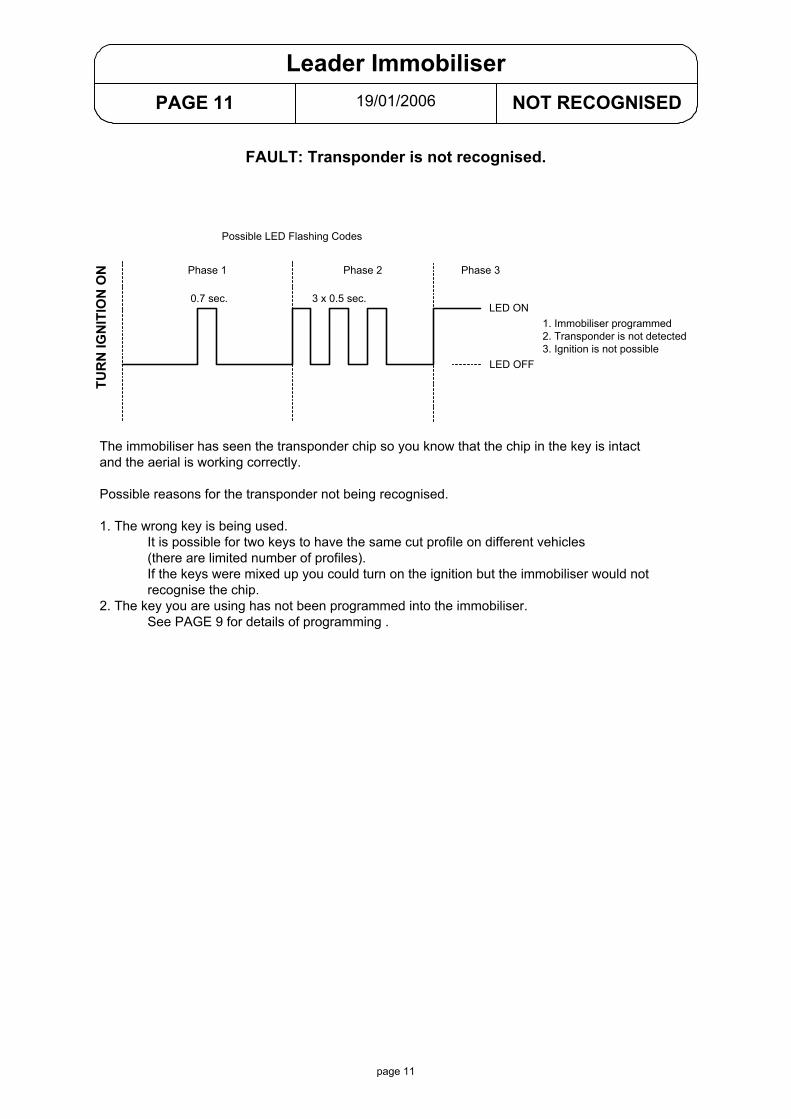
FAULT: Transponder is not recognised.
The immobiliser has seen the transponder chip so you know that the chip in the key is intactand the aerial is working correctly.
Possible reasons for the transponder not being recognised.
1. The wrong key is being used.It is possible for two keys to have the same cut profile on different vehicles(there are limited number of profiles).If the keys were mixed up you could turn on the ignition but the immobiliser would notrecognise the chip.
2. The key you are using has not been programmed into the immobiliser.See PAGE 9 for details of programming .
page 11
19/01/2006PAGE 12 EXPLANATION
Non Leader Immobiliser
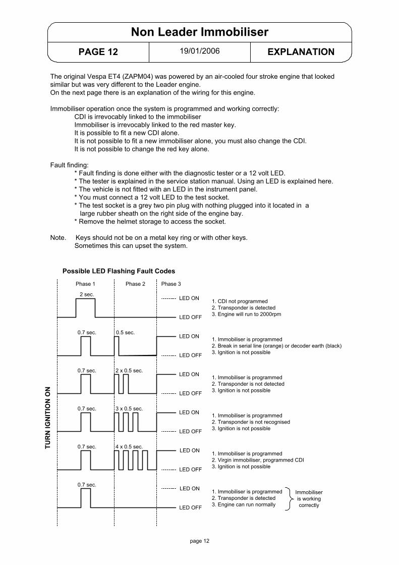
The original Vespa ET4 (ZAPM04) was powered by an air-cooled four stroke engine that lookedsimilar but was very different to the Leader engine.On the next page there is an explanation of the wiring for this engine.
Immobiliser operation once the system is programmed and working correctly:CDI is irrevocably linked to the immobiliserImmobiliser is irrevocably linked to the red master key.It is possible to fit a new CDI alone.It is not possible to fit a new immobiliser alone, you must also change the CDI.It is not possible to change the red key alone.
Fault finding:* Fault finding is done either with the diagnostic tester or a 12 volt LED.* The tester is explained in the service station manual. Using an LED is explained here.* The vehicle is not fitted with an LED in the instrument panel.* You must connect a 12 volt LED to the test socket.* The test socket is a grey two pin plug with nothing plugged into it located in a large rubber sheath on the right side of the engine bay.* Remove the helmet storage to access the socket.
Note. Keys should not be on a metal key ring or with other keys. Sometimes this can upset the system.
page 12
Possible LED Flashing Fault Codes
TUR
N IG
NIT
ION
ON
LED OFF
LED ON
0.5 sec.0.7 sec.
Phase 1 Phase 2 Phase 3
1. CDI not programmed2. Transponder is detected3. Engine will run to 2000rpm
LED OFF
LED ON 1. Immobiliser is programmed2. Break in serial line (orange) or decoder earth (black)3. Ignition is not possible
2 sec.
2 x 0.5 sec.0.7 sec.
LED OFF
LED ON 1. Immobiliser is programmed2. Transponder is not detected3. Ignition is not possible
3 x 0.5 sec.0.7 sec.
LED OFF
LED ON 1. Immobiliser is programmed2. Transponder is not recognised3. Ignition is not possible
0.7 sec.
LED ON
LED OFF
1. Immobiliser is programmed2. Transponder is detected3. Engine can run normally
4 x 0.5 sec.0.7 sec.1. Immobiliser is programmed2. Virgin immobiliser, programmed CDI3. Ignition is not possible
LED ON
LED OFF
Immobiliseris workingcorrectly
19/01/2006PAGE 13 ZAPM 04 Later version
Vespa ET4 125 charge / ignition (non Leader)
VOLTAGESTABILISER
DECODER
3 5 8 6 4
CDI UNIT
3 2 1V G W B R
ORANGE
ANTENNA
(Serial Line)
DCSERVICES
ACSERVICES
GREEN
GREEN
WHITE
BROWN
RED
YELLOW
LIGHT BLUE
LIGHT BLUE
WHITE / RED
PINK
LIGHT BLUE
BLACK / BLUE
PIN
K
Lt. BLUE
BLUE
BLUE
WHITE
WHITE
PURPLE
GR
EY /
BLU
E
GREY
GR
EY
WH
ITE
YELL
OW
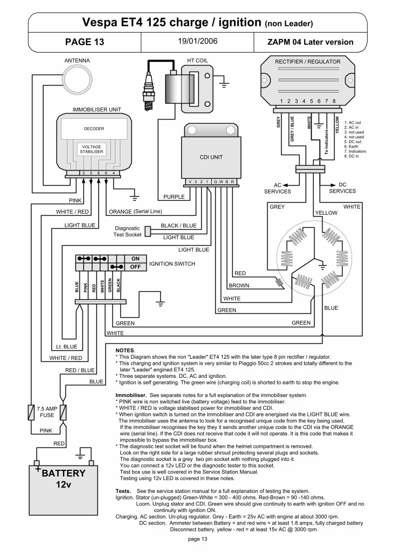
NOTES.* This Diagram shows the non "Leader" ET4 125 with the later type 8 pin rectifier / regulator.* This charging and ignition system is very similar to Piaggio 50cc 2 strokes and totally different to the later "Leader" engined ET4 125.* Three separate systems. DC, AC and ignition.* Ignition is self generating. The green wire (charging coil) is shorted to earth to stop the engine.
Immobiliser. See separate notes for a full explanation of the immobiliser system.* PINK wire is non switched live (battery voltage) feed to the immobiliser.* WHITE / RED is voltage stabilised power for immobiliser and CDI.* When ignition switch is turned on the immobiliser and CDI are energised via the LIGHT BLUE wire. The immobiliser uses the antenna to look for a recognised unique code from the key being used. If the immobiliser recognises the key they it sends another unique code to the CDI via the ORANGE wire (serial line). If the CDI does not receive that code it will not operate. It is this code that makes it impossible to bypass the immobiliser box.* The diagnostic test socket will be found when the helmet compartment is removed. Look on the right side for a large rubber shroud protecting several plugs and sockets. The diagnostic socket is a grey two pin socket with nothing plugged into it. You can connect a 12v LED or the diagnostic tester to this socket. Test box use is well covered in the Service Station Manual. Testing using 12v LED is covered in these notes.
Tests. See the service station manual for a full explanation of testing the system.Ignition. Stator (un-plugged) Green-White = 300 - 400 ohms. Red-Brown = 90 -140 ohms. Loom. Unplug stator and CDI. Green wire should give continuity to earth with ignition OFF and no continuity with ignition ON.Charging. AC section. Un-plug regulator. Grey - Earth = 25v AC with engine at about 3000 rpm. DC section. Ammeter between Battery + and red wire = at least 1.8 amps, fully charged battery Disconnect battery. yellow - red = at least 15v AC @ 3000 rpm.
IMMOBILISER UNIT
RED / BLUE
21 3 4 5 6 7 8
RECTIFIER / REGULATOR
1. AC out2. AC in3. not used4. not used5. DC out6. Earth7. Indicators8. DC in
HT COIL
BATTERY12v
+
7.5 AMPFUSE
PINK
RED
DiagnosticTest Socket
OFFON
IGNITION SWITCH
To In
dica
tors
WHITE / RED
GREEN
BLU
E
WH
ITE
RED
GR
EEN
BLA
CK
page 13

19/01/2006PAGE 14 EXPLANATION
Quasar Immobiliser
page 14
The 250 cc Quasar engine is available with a CV carburettor or semi closed loop fuel injection.The Quasar engine with a carburettor has exactly the same immobiliser function as a Leaderengine.The Injected engine is detailed below.This is only a quick reference guide for basic fault finding of the immobiliser system.For a full explanation please see the Service Station manual.
The Quasar has an ECU with a separate immobiliser which is built into the aerial, so the ECU mustobtain authority from the aerial (active antenna).
Keys should not be on a metal key ring or with other keys. Sometimes this can upset the system.
Possible LED Flashing Codes
TUR
N IG
NIT
ION
ON
LED OFF
LED ON
0.5 sec.0.7 sec.
Phase 1 Phase 2 Phase 3
1. ECU not programmed2. Transponder is detected3. Engine will run to 2000rpm
LED OFF
LED ON 1. Immobiliser is programmed2. Break in serial line (ECU to aerial)3. Ignition is not possible
2 sec.
2 x 0.5 sec.0.7 sec.
LED OFF
LED ON 1. Immobiliser is programmed2. Transponder is not detected3. Ignition is not possible
3 x 0.5 sec.0.7 sec.
LED OFF
LED ON 1. Immobiliser is programmed2. Transponder is not recognised3. Ignition is not possible
0.7 sec.1. Immobiliser is programmed2. Transponder is detected3. Engine can run normally
LED ON
LED OFF
LED OFF
LED ON 1. ECU not programmed2. Transponder is not detected3. Ignition is not possible
AnyKey
AnyKey
ServiceKey
MasterKey
ServiceKey
ServiceKey
ServiceKey
2 x 0.5 sec.0.7 sec.
LED OFF
LED ON 1. Immobiliser is programmed2. Two service keys are programmed3. Engine can run normally
Immobiliseris workingcorrectly
Could beany numberfrom 0 to 7
A
B
C
D
E
See Noteon the
Next Page
19/01/2006PAGE 15 NOTES
Quasar Immobiliser
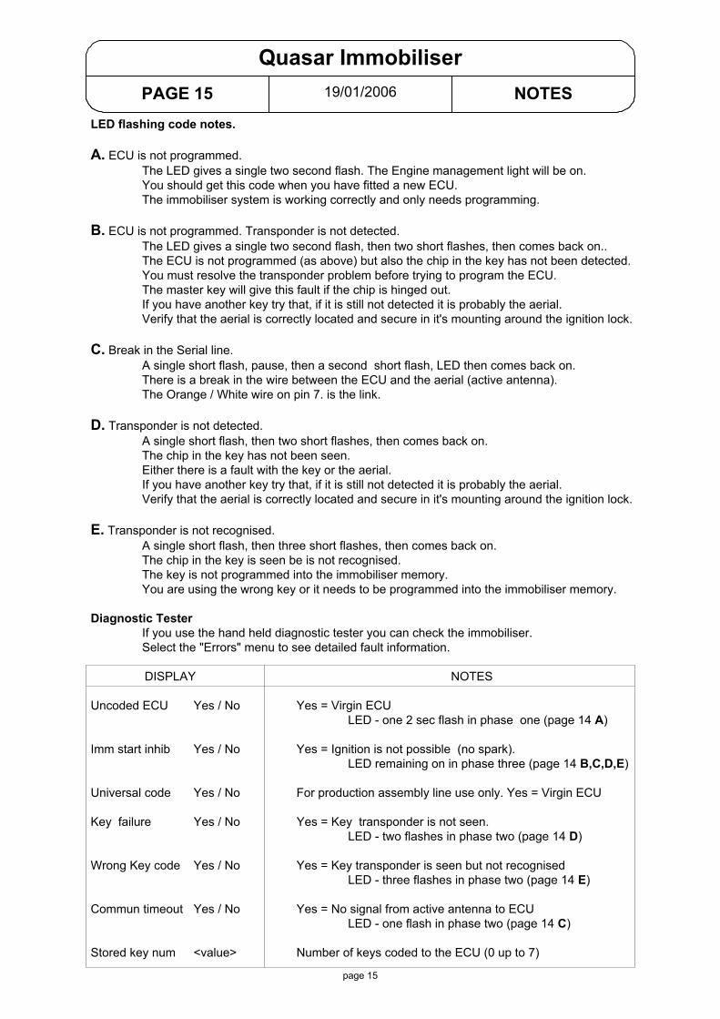
LED flashing code notes.
A. ECU is not programmed.The LED gives a single two second flash. The Engine management light will be on.You should get this code when you have fitted a new ECU.The immobiliser system is working correctly and only needs programming.
B. ECU is not programmed. Transponder is not detected.The LED gives a single two second flash, then two short flashes, then comes back on..The ECU is not programmed (as above) but also the chip in the key has not been detected.You must resolve the transponder problem before trying to program the ECU.The master key will give this fault if the chip is hinged out.If you have another key try that, if it is still not detected it is probably the aerial.Verify that the aerial is correctly located and secure in it's mounting around the ignition lock.
C. Break in the Serial line.A single short flash, pause, then a second short flash, LED then comes back on.There is a break in the wire between the ECU and the aerial (active antenna).The Orange / White wire on pin 7. is the link.
D. Transponder is not detected.A single short flash, then two short flashes, then comes back on.The chip in the key has not been seen.Either there is a fault with the key or the aerial.If you have another key try that, if it is still not detected it is probably the aerial.Verify that the aerial is correctly located and secure in it's mounting around the ignition lock.
E. Transponder is not recognised.A single short flash, then three short flashes, then comes back on.The chip in the key is seen be is not recognised.The key is not programmed into the immobiliser memory.You are using the wrong key or it needs to be programmed into the immobiliser memory.
Diagnostic TesterIf you use the hand held diagnostic tester you can check the immobiliser.Select the "Errors" menu to see detailed fault information.
DISPLAY NOTES
Uncoded ECU Yes / No Yes = Virgin ECULED - one 2 sec flash in phase one (page 14 A)
Imm start inhib Yes / No Yes = Ignition is not possible (no spark).LED remaining on in phase three (page 14 B,C,D,E)
Universal code Yes / No For production assembly line use only. Yes = Virgin ECU
Key failure Yes / No Yes = Key transponder is not seen.LED - two flashes in phase two (page 14 D)
Wrong Key code Yes / No Yes = Key transponder is seen but not recognisedLED - three flashes in phase two (page 14 E)
Commun timeout Yes / No Yes = No signal from active antenna to ECULED - one flash in phase two (page 14 C)
Stored key num <value> Number of keys coded to the ECU (0 up to 7)
page 15

Programming.
Notes.
1. It is not possible to re-program an immobiliser unit to a new master key.Once it has been programmed it is irrevocably linked to that master key.
2. It is not normally possible for an immobiliser to loose it's program and then needre-programming.If it was programmed and working but now it is saying that it is not programmed,First, check the HT lead and plug cap, It is possible that extreme electricalinterference from a faulty HT circuit could upset the immobiliser.Plug cap must be at least 5000 ohms. Change the cap and lead if suspect.A resistor spark plug must be used.Then try re-programming the immobiliser.If it will not re-program then it is faulty.
Programming a new immobiliser.
1. Do not attempt to program a new immobiliser until you know that the fault is cured.Connect the new immobiliser, use the service key (not the brown master key)LED will give one long flash then go out and stay out. System is working correctly,Immobiliser is not programmedThe engine should start but will not rev above 2000 rpm until the immobiliser isprogrammed.
2. To program a new immobiliser* Insert the brown master key and turn on for two seconds* Insert the service key and turn on for two seconds* (any extra service keys are included here)
- Insert the extra service key and turn on for two seconds* Insert the brown master key and turn on for two seconds
* The timing of the two seconds can be critical so use a watch to time it, you may need to do the sequence several times before it is accepted.* Changing from one key to the next should be done within ten seconds.* An extra service key is not just added, you must go through re-programming all the keys as above. You are not re-programming the master key, the master key is giving permission for the service keys to be added.* It is not the keys that are programmed. The immobiliser is being programmed to recognise the keys.* You do not need to start the engine just to check if the programming has been successful, Just turn on the ignition and watch the LED. One short flash (half second) means the programming was successful. One long flash (two seconds) means the system is still not programmed.
19/01/2006PAGE 16 PROGRAMMING
Quasar Immobiliser
page 16

19/01/2006PAGE 17 EXPLANATION
Master Immobiliser
page 17
The 500 cc Master engine has separate immobiliser and ECU.Once the system is programmed the ECU and immobiliser are irrevocably linked to the brownmaster key.
Keys should not be on a metal key ring or with other keys. Sometimes this can upset the system.
For a full explanation of fault finding please see the Service Station manual.
Possible LED Flashing Codes
TUR
N IG
NIT
ION
ON
0.5 sec.0.7 sec.
Phase 1 Phase 2 Phase 3
LED OFF
LED ON 1. Immobiliser is programmed2. Break in serial line3. Ignition is not possible
2 x 0.5 sec.0.7 sec.
LED OFF
LED ON 1. Immobiliser is programmed2. Transponder is not detected3. Ignition is not possible
3 x 0.5 sec.0.7 sec.
LED OFF
LED ON 1. Immobiliser is programmed2. Transponder is not recognised3. Ignition is not possible
0.7 sec.1. Immobiliser is programmed2. Transponder is detected3. Engine can run normally
LED ON
LED OFF
LED OFF
LED ON 1. Immobiliser not programmed2. ECU is programmed3. Ignition is not possible
2 sec.
AnyKey
ServiceKey
MasterKey
ServiceKey
ServiceKey
ServiceKey
2 x 0.5 sec.0.7 sec.
LED OFF
LED ON 1. Immobiliser is programmed2. Two service keys are programmed3. Engine can run normally
Immobiliseris workingcorrectly
Could beany numberfrom 0 to 7
A
B
C
D
See Noteon the
Next Page
E
2 sec.1. System not programmed2. Transponder is detected3. Engine runs only to 2000 rpm.
LED ON
LED OFF
AnyKey

19/01/2006PAGE 18 NOTES
Master Immobiliser
LED flashing code notes.
A. System is not programmed.The LED gives a single two second flash. The Engine management light will be on.You should get this code when you have fitted a new immobiliser and ECU.The immobiliser system is working correctly and only needs programming.
B. Immobiliser is not programmed, ECU is programmed.The LED gives one long flash, then four short flashes, LED then comes back on.Programming the immobiliser is only possible if the original master key is used.If the original master key (chip) is not available then you must change the ECU as well.
C. Break in the Serial line.A single short flash, pause, then a second short flash, LED then comes back on.Either there is a break in the orange / white wire between the immobiliser and ECU(serial line) or if the vehicle has a "fall over cut out" fitted it could be that.If the cut out is active it shorts the serial line to earth.The fall over sensor is located behind the fuel tank (Nexus) in a rubber mounting.
The fall over sensor must be mounted
THIS WAY UP
D. Transponder is not detected.A single short flash, then two short flashes, then comes back on.The chip in the key has not been seen.Either there is a fault with the key or the aerial.If you have another key try that, if it is still not detected it is probably the aerial or it's wires.Un-plug the aerial from the immobiliser and check for continuity.Check that the aerial is correctly located and secure in it's mounting.
E. Transponder is not recognised.A single short flash, then three short flashes, then comes back on.The chip is seen be is not recognised. The key is not programmed into the immobiliser.You are using the wrong key or it needs to be programmed into the immobiliser memory.
page 18
Programming.
Notes.
1. It is not possible to re-program an immobiliser unit to a new master key.Once it has been programmed it is irrevocably linked to that master key.
2. It is not normally possible for an immobiliser to loose it's program and then needre-programming.If it was programmed and working but now it is saying that it is not programmed,First, check the HT lead and plug cap, It is possible that extreme electricalinterference from a faulty HT circuit could upset the immobiliser.Plug cap must be at least 5000 ohms. Change the cap and lead if suspect.Also a resistor spark plug must be used.Then try re-programming the immobiliser.If it will not re-program then it is faulty.
Programming a new immobiliser.
1. Do not attempt to program a new immobiliser until you know that the fault is cured.Connect the new immobiliser, use the service key (not the brown master key)LED will give one long flash then go out and stay out. System is working correctly,Immobiliser is not programmedThe engine should start but will not rev above 2000 rpm until the immobiliser isprogrammed.
2. To program a new immobiliser* Insert the brown master key and turn on for two seconds* Insert the service key and turn on for two seconds* (any extra service keys are included here)
- Insert the extra service key and turn on for two seconds* Insert the brown master key and turn on for two seconds
* The timing of the two seconds can be critical so use a watch to time it, you may need to do the sequence several times before it is accepted.* Changing from one key to the next should be done within ten seconds.* An extra service key is not just added, you must go through re-programming all the keys as above. You are not re-programming the master key, the master key is giving permission for the service keys to be added.* It is not the keys that are programmed. The immobiliser is being programmed to recognise the keys.* You do not need to start the engine just to check if the programming has been successful, Just turn on the ignition and watch the LED. One short flash (half second) means the programming was successful. One long flash (two seconds) means the system is still not programmed.
19/01/2006PAGE 19 PROGRAMMING
Master Immobiliser
page 19

30/09/2005Piaggio Ltd. With IMMOBILISER
Vespa GT 125 / 200 ignition / charging
2 -13
Rectifier / Regulatorp/n: 82501R
GALTERNATORSTATOR
ToIndicatorswitch
Red
Green
Green
White / Black
Yellow
IgnitionPick up
ECU / Immobiliser
HT Coil
Main15amp
Orange
Orange
PurpleRed / Black
Red / Black
Black
Yellow
Red / BlueLED on
instrumentpannel
Layout of pinsin the ECU / immobiliser
BATTERY12v
12ah
+
RG4HCCR 9EB
CoolingFan
FanSwitch
Green
Choke Unit
Lt. Blue
Orange
GREEN
WHITE / BLACKLt. BLUE
RED / BLACK
PURPLEBLACK
BLUE / BLACK
YELLOW
3 2 18 7 6 5 4
Note that the ECU fitted to the 125 and 200 have different characteristics.They are NOT interchangeable.
TESTS.STATOR: ANY YELLOW TO ANY YELLOW = 0.7 - 0.9 ohm.
YELLOW TO EARTH = NO CONTINUITY GREEN TO BLACK (EARTH) = 105 - 124 ohm
REGULATOR: VOLTAGE ACROSS A FULLY CHARGED BATTERY, LIGHTS OFF, HIGH REVS = 14 - 15.2 V.
CHARGING: AMMETER IN RED WIRE = > 8 AMPS WITH LIGHTS ON AND HIGH REVS.
HT COIL: PRIMARY = 0.4 - 0.5 OHM. SECONDARY = 3K + 300 OHM.
STOP
RUN
6 1
8 3
4 5
7 2
antenna
Fuses inglove box
Red / Black
IgnitionSwitch
OFF
ON
LOCK
Seat releasepush button
Seat lock
Grey
Grey / BlueGrey / Black

WHITE / RED
YELLOW / BLACK
YELLOW / REDWHITE
RED / BLUE
GREY
RED / BLACK12v DC from battery
ORANGESwitched 12v
ORANGESwitched 12v
BLUE
BLUE
RED / BLACK12v DC from battery
19/08/2003Piaggio Ltd.
Vespa GT Fuses
3
7.5a
1
10a
2
7.5a
4
7.5a
5
5a
6
5a
The wire colours shown here are different to those "on line" and in the owners handbook.The colours and fuse functions here are correct, they were checked on GT200ZAPM312 * 2550.
FUSE:1. 10 amp. Electric seat release. Headlights. Main beam warning light.2. 7.5 amp. Intercom. Alarm. Immobiliser LED.3. 7.5 amp. Intercom. Alarm. Water temp. Fuel warning & guage. Oil pressure warning.4. 7.5 amp. Horn.5. 5 amp. Stop light. start switch.6. 5 amp. Side lights. Number plate light. Instrument panel lights.
MAIN FUSE.A 15 amp fuse is located at the front of the under seat compartment.
2-14

Rectifier /Regulatorp/n: 82501R
30/09/05Piaggio Ltd. With IMMOBILISER
Skipper ST ignition / charging
GALTERNATORSTATOR
ToIndicatorswitch
Headlightvia relay
Red
Green
Green
White /Black
Red / Blue
RG4HCCR 9E
Carb. Heater
Choke Unit
Yellow
IgnitionPick up
ECU / Immobiliser
IgnitionSwitch
HT Coil
Blue /Black
15amp
Ora
nge
Orange
Red
/Blu
e
Purple
Grey
Red / Blue
Powerto
services
Red / Blue
Black
antenna
Yellow
LED oninstrument
pannel
6 1
8 3
4 5
7 2 GREEN
WHITE / BLACKORANGE
RED / BLUE
PURPLEBLACK
BLUE / BLACK
YELLOW
Layout of pinsin the ECU / immobiliser
BATTERY12v9ah
+
3 2 18 7 6 5 4
TESTS.STATOR: ANY YELLOW TO ANY YELLOW = 0.7 - 0.9 ohm.
YELLOW TO EARTH = NO CONTINUITY GREEN TO BLACK (EARTH) = 105 - 124 ohm
REGULATOR: VOLTAGE ACROSS A FULLY CHARGED BATTERY, LIGHTS OFF, HIGH REVS = 14 - 15.2 V.
CHARGING: AMMETER IN RED WIRE = > 8 AMPS WITH LIGHTS ON AND HIGH REVS.
HT COIL: PRIMARY = 0.4 - 0.5 OHM. SECONDARY = 3K + 300 OHM.
OFF
ON
2-15

RED / BLUE
ORANGE
RED / BLUE
RED / BLUERED
06/01/2004Piaggio Ltd. Leader Engine
SKIPPER ST 125 FUSE EXPLANATION
RED12 V DC from battery
3
5a
1
7.5a
2
5a
4
5a
RED / WHITEClock & Interphone Socket
RED / BLACKTo Light Switch
GREY / REDTo Main / Dip Switch
WHITEGeneral
2 15 amp
1 15 ampGREYTo Head Light Relay
OFF
ON
IGNITION SWITCH
2-16
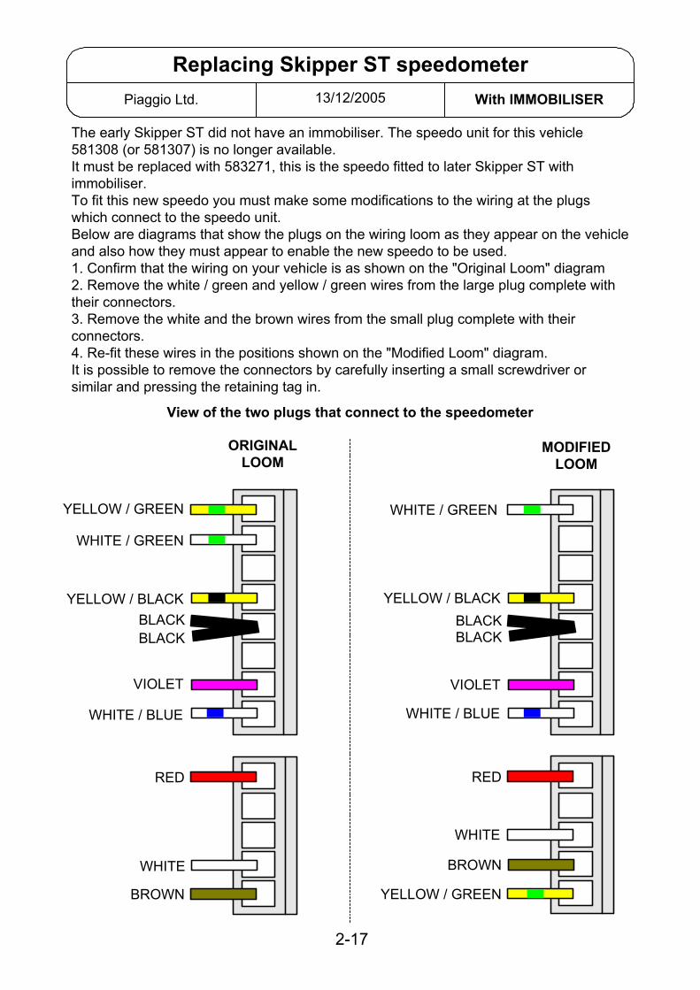
The early Skipper ST did not have an immobiliser. The speedo unit for this vehicle581308 (or 581307) is no longer available.It must be replaced with 583271, this is the speedo fitted to later Skipper ST withimmobiliser.To fit this new speedo you must make some modifications to the wiring at the plugswhich connect to the speedo unit.Below are diagrams that show the plugs on the wiring loom as they appear on the vehicleand also how they must appear to enable the new speedo to be used.1. Confirm that the wiring on your vehicle is as shown on the "Original Loom" diagram2. Remove the white / green and yellow / green wires from the large plug complete withtheir connectors.3. Remove the white and the brown wires from the small plug complete with theirconnectors.4. Re-fit these wires in the positions shown on the "Modified Loom" diagram.It is possible to remove the connectors by carefully inserting a small screwdriver orsimilar and pressing the retaining tag in.
View of the two plugs that connect to the speedometer
2-17
13/12/2005Piaggio Ltd. With IMMOBILISER
Replacing Skipper ST speedometer
ORIGINALLOOM
WHITE / BLUE
VIOLET
BLACKYELLOW / BLACK
WHITE / GREEN
YELLOW / GREEN
BLACK
MODIFIEDLOOM
WHITE / BLUE
VIOLET
BLACKYELLOW / BLACK
WHITE / GREEN
YELLOW / GREEN
BLACK
RED
WHITE
BROWN
RED
WHITE
BROWN
Rectifier /Regulator
05/05/2004Piaggio Ltd. QUASAR Engine
X9 250 Evo ignition / charging
GALTERNATORSTATOR
Red
Green
Green
White / Black
Yellow
IgnitionPick up
ECU / Immobiliser
IgnitionSwitch
15amp
Orange
Orange
Red / Black
Yellow
Layout of pinsin the ECU / immobiliser
Yellow / Grey
BATTERY12v
12ah
+
CoolingFan
Fan Switch
Red / Black
Green
Choke Unit
EmergencyStop
Lt. Blue
Orange
7.5amp
Diagnosticsocket
2 GREEN
7 WHITE / BLACK
5 Lt. BLUE
4 RED / BLACK
3 PURPLE8 BLACK
6 YELLOW
Red / Black
Yellow / BlueYellow / Green
Gre
y / B
lack
Lt. Blue
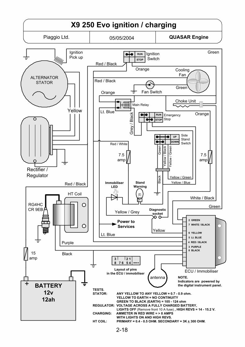
TESTS.STATOR: ANY YELLOW TO ANY YELLOW = 0.7 - 0.9 ohm.
YELLOW TO EARTH = NO CONTINUITY GREEN TO BLACK (EARTH) = 105 - 124 ohm
REGULATOR: VOLTAGE ACROSS A FULLY CHARGED BATTERY, LIGHTS OFF (Remove front 10 A fuse) , HIGH REVS = 14 - 15.2 V.
CHARGING: AMMETER IN RED WIRE = > 8 AMPS WITH LIGHTS ON AND HIGH REVS.
HT COIL: PRIMARY = 0.4 - 0.5 OHM. SECONDARY = 3K + 300 OHM.
3 2 18 7 6 5 4
RG4HCCR 9EB
HT Coil
Purple
Black
SideStandSwitchRed / White
STOP
RUN
STOP
RUN
UP
DOWN
2-18
ImmobiliserLED
StandWarning
Power toServices
antenna NOTE.Indicators are powered bythe digital instrument panel.
7.5amp
Gre
en
Yel
low
/ G
reen
Yel
low
/ Bl
ack
Bla
ck
Main Relay

25/01/2006Piaggio Ltd
Fly 125 Instrument connection
You may find an incorrect wiring diagram, with wiring that does not match the vehicle.This diagram should match the vehicle.
Immobiliser LED.The LED has a permanent live feed, the CDI earths it when it wants it to light.If the battery is connected the LED should have a live feed on the Red / Blue wireIf you short the Yellow / Red wire to earth the LED should light.Oil Pressure.Live feed to switch. Switch shorts it to earth to light the bulb.Fuel Gauge.Live feed to unit in tank. The tank unit shorts it to earth via a variable resistor.If the gauge is not working.Un-plug the instruments put a meter between white / green and black.Low resistance (3 ohms) = full tank. High resistance (100 ohms) = empty tank.This has checked the wiring and tank unit.Low Fuel Warning.Live feed to unit in tank. The tank units shorts to earth to light the bulb.
Oil Pressure
Left turnsignal
High beam
Earth
Yellow / RedTo CDI unit
Red / Blue12v +
Right turnsignal
Low fuelwarning
SwitchedLive
InstrumentIllumination
Fuel gauge
BLACKVIOLET
WHITE / BLUE
BROWNPINK
WHITE / GREENWHITEYELLOW / GREEN
YELLOW / BLACK
5
4
3
2
1
2-19 A

Rectifier /Regulatorp/n: 82501R
21/10/04Piaggio Ltd. With IMMOBILISER
Fly 125 ignition / charging
GALTERNATORSTATOR
ToIndicatorswitch
Red
Green
Green
Whi
te /
Bla
ck
Red / Blue
RG4HCCR 9E
Yellow
IgnitionPick up
ECU / Immobiliser
IgnitionSwitch
HT Coil
Blue / Black
15amp
Ora
nge
Orange
White
Red
/ B
lue
Purple
Red / Blue
Powerto
services
Red / BlueB
lack
antenna
Yellow
LED oninstrument
pannel
Diagnosticsocket
6 1
8 3
4 5
7 2 GREEN
WHITE / BLACKORANGE
RED / BLUE
PURPLEBLACK
BLUE / BLACK
YELLOW
Layout of pinsin the ECU / immobiliser
Orange
7.5amp
BATTERY12v9ah
+
3 2 18 7 6 5 4
TESTS.STATOR: ANY YELLOW TO ANY YELLOW = 0.7 - 0.9 ohm.
YELLOW TO EARTH = NO CONTINUITY GREEN TO BLACK (EARTH) = 105 - 124 ohm
REGULATOR: VOLTAGE ACROSS A FULLY CHARGED BATTERY, LIGHTS OFF, HIGH REVS = 14 - 15.2 V.
CHARGING: AMMETER IN RED WIRE = > 8 AMPS WITH LIGHTS ON AND HIGH REVS.
HT COIL: PRIMARY = 0.4 - 0.5 OHM. SECONDARY = 3K + 300 OHM.
OFF
ON
2-19
Carb. Heater
Choke Unit
Yellow / Red
Toheadlight
switchO
rang
e

Rectifier /Regulator
04/01/2005Piaggio Ltd. With IMMOBILISER
X8 125 / 200 ignition / charging
GALTERNATORSTATOR
Red
Green
Green
White / Black
Yellow
IgnitionPick up
IgnitionSwitch
15
Orange
Red
Yellow
Layout of pinsin the ECU / immobiliser
Yel
low
/ B
lue
BATTERY12v
12ah
+
CoolingFan
Fan Switch
Red
Green
Choke Unit
EmergencyStop
Lt. Blue
Orange
Diagnosticsocket
Red
TESTS.STATOR: ANY YELLOW TO ANY YELLOW = 0.7 - 0.9 ohm.
YELLOW TO EARTH = NO CONTINUITY GREEN TO BLACK (EARTH) = 105 - 124 ohm
REGULATOR: VOLTAGE ACROSS A FULLY CHARGED BATTERY, LIGHTS OFF, HIGH REVS = 14 - 15.2 V.
CHARGING: AMMETER IN RED WIRE = > 8 AMPS WITH LIGHTS ON AND HIGH REVS.
HT COIL: PRIMARY = 0.4 - 0.5 OHM. SECONDARY = 3K + 300 OHM.
3 2 18 7 6 5 4
RG4HCCR 9EB
HT Coil
Purple
Black
Red
/ G
reen
STOP
RUN
STOP
RUN
2-20
ImmobiliserLED
Power toServices
antenna
Red
/ B
lack
Red / BlueRed / Black
10
5
Rear FuseBox
To IndicatorSwitch
ECU / Immobiliser
2 GREEN7 WHITE / BLACK
5 Lt. BLUE
4 RED
3 PURPLE
8 BLACK
6 YELLOW
1 BLACK / BLUE
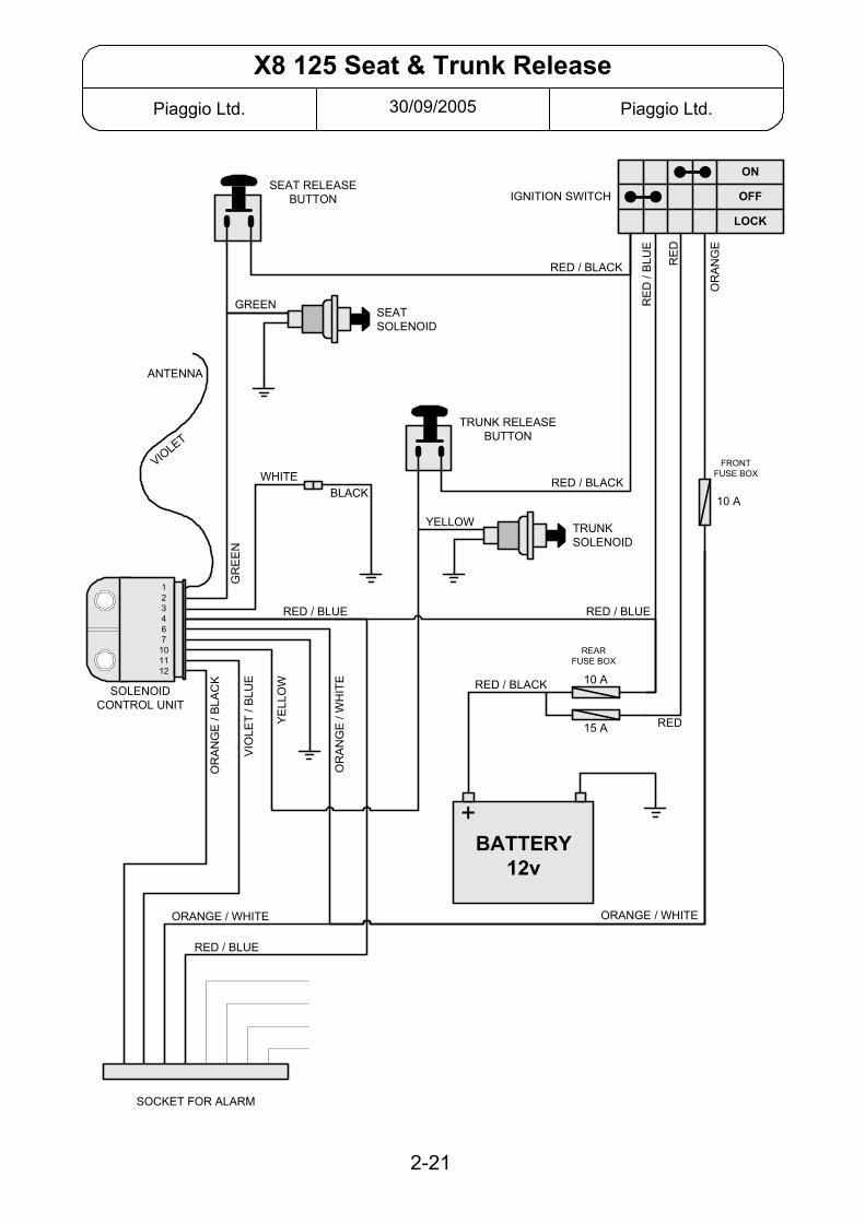
30/09/2005Piaggio Ltd. Piaggio Ltd.
X8 125 Seat & Trunk Release
2-21
GREEN
LOCK
OFF
ON
RED / BLACK
BATTERY12v
+
RED / BLUE
ORANGE / WHITE
OR
AN
GE
123467
101112
RED / BLACK
SEAT RELEASEBUTTON
TRUNKSOLENOID
TRUNK RELEASEBUTTON
SEATSOLENOID
IGNITION SWITCH
SOLENOIDCONTROL UNIT
ANTENNA
10 A
WHITE
OR
AN
GE
/ W
HIT
E
YE
LLO
W
VIO
LET
/ BLU
E
OR
AN
GE
/ B
LAC
K
ORANGE / WHITE
YELLOW
BLACK
RE
D /
BLU
E
RE
D
RED
RED / BLACK
RED / BLUE
VIOLET
SOCKET FOR ALARM
RED / BLUE
10 A
15 A
FRONTFUSE BOX
GR
EE
N
REARFUSE BOX
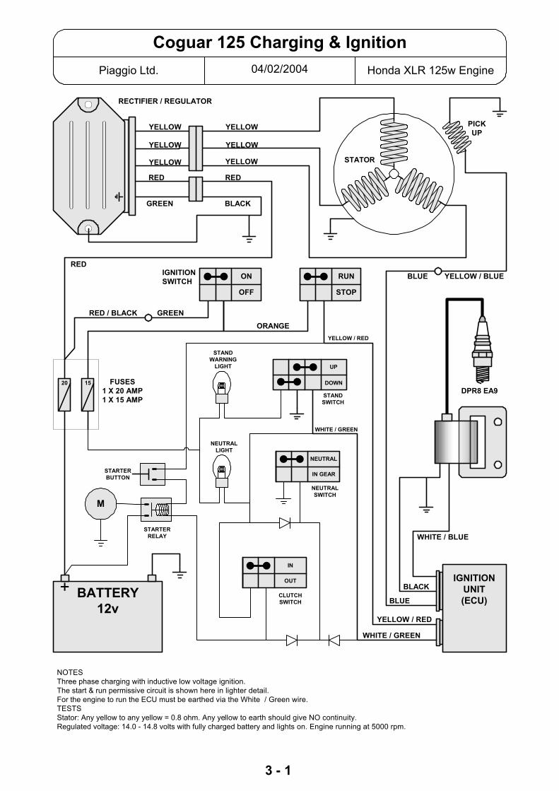
04/02/2004Piaggio Ltd. Honda XLR 125w Engine
Coguar 125 Charging & Ignition
RECTIFIER / REGULATOR
BLUE YELLOW / BLUE
ORANGE
YELLOW
YELLOW
YELLOW
YELLOW
YELLOW
YELLOW
RED
GREEN BLACK
RED
RED
NOTESThree phase charging with inductive low voltage ignition.The start & run permissive circuit is shown here in lighter detail.For the engine to run the ECU must be earthed via the White / Green wire.TESTSStator: Any yellow to any yellow = 0.8 ohm. Any yellow to earth should give NO continuity.Regulated voltage: 14.0 - 14.8 volts with fully charged battery and lights on. Engine running at 5000 rpm.
DPR8 EA9FUSES
1 X 20 AMP1 X 15 AMP
STATOR
PICKUP
WHITE / BLUE
BLACK
BLUE
YELLOW / RED
WHITE / GREEN
IGNITIONUNIT(ECU)
STOP
RUN
OFF
ONIGNITIONSWITCH
RED / BLACK GREEN
WHITE / GREEN
YELLOW / RED
3 - 1
M
STARTERBUTTON
STARTERRELAY
NEUTRALLIGHT
STANDWARNING
LIGHT
BATTERY12v
+
NEUTRALSWITCH
NEUTRAL
IN GEAR
CLUTCHSWITCH
IN
OUT
STANDSWITCH
DOWN
UP
20 15
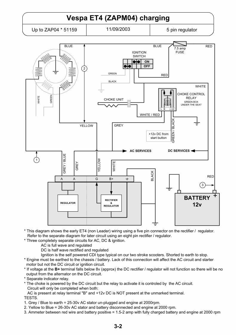
11/09/2003Up to ZAP04 * 51159 5 pin regulator
Vespa ET4 (ZAPM04) charging
7.5 ampFUSE
YELLOW
BLUE RED
DC SERVICES
RED
WHITE
* This diagram shows the early ET4 (non Leader) wiring using a five pin connector on the rectifier / regulator. Refer to the separate diagram for later circuit using an eight pin rectifier / regulator.* Three completely separate circuits for AC, DC & ignition.
AC is full wave and regulatedDC is half wave rectified and regulatedIgnition is the self powered CDI type typical on our two stroke scooters. Shorted to earth to stop.
* Engine must be earthed to the chassis / battery. Lack of this connection will affect the AC circuit and starter motor but not the DC circuit or ignition circuit.* If voltage at the B+ terminal falls below 8v (approx) the DC rectifier / regulator will not function so there will be no output from the alternator on the DC circuit.* Separate indicator relay.* The choke is powered by the DC circuit but the relay to activate it is controled by the AC circuit. Circuit will only be completed when both: AC is present at relay terminal "B" and +12v DC is NOT present at the unmarked terminal.TESTS.1. Grey / Blue to earth = 25-30v AC stator un-plugged and engine at 2000rpm.2. Yellow to Blue = 26-30v AC stator and battery disconnected and engine at 2000 rpm.3. Ammeter between red wire and battery positive = 1.5-2 amp with fully charged battery and engine at 2000 rpm
AC SERVICES
CHOKE UNIT
2
GR
EEN
GREY
WHITE / RED
CHOKE CONTROLRELAY
GREEN BOXUNDER THE SEAT
L EB (-)
+12v DC fromstart button
GR
EEN
/ BL
ACK
IGNITIONSWITCH
OFFON
BLUE
WH
ITE
GREEN
BLACK
BATTERY12v
+
BLAC
K
1
3
RED
WH
ITE
YELL
OW
GR
EY /
BLU
E
GR
EY
RECTIFIER&
REGULATOR
B+GAA
REGULATOR
3-2
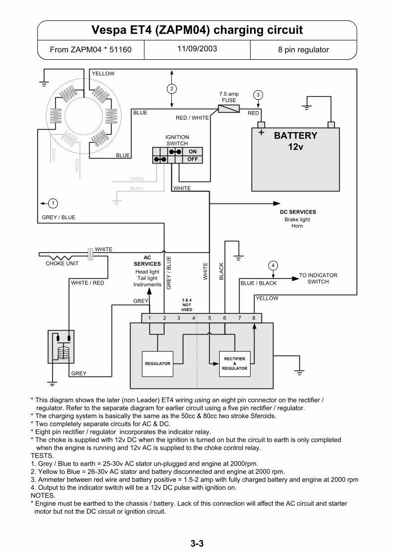
11/09/2003From ZAPM04 * 51160 8 pin regulator
Vespa ET4 (ZAPM04) charging circuit
BATTERY12v
+
7.5 ampFUSE
RED / WHITE
DC SERVICESBrake light
Horn
RED
* This diagram shows the later (non Leader) ET4 wiring using an eight pin connector on the rectifier / regulator. Refer to the separate diagram for earlier circuit using a five pin rectifier / regulator.* The charging system is basically the same as the 50cc & 80cc two stroke Sferoids.* Two completely separate circuits for AC & DC.* Eight pin rectifier / regulator incorporates the indicator relay.* The choke is supplied with 12v DC when the ignition is turned on but the circuit to earth is only completed when the engine is running and 12v AC is supplied to the choke control relay.TESTS.1. Grey / Blue to earth = 25-30v AC stator un-plugged and engine at 2000rpm.2. Yellow to Blue = 26-30v AC stator and battery disconnected and engine at 2000 rpm.3. Ammeter between red wire and battery positive = 1.5-2 amp with fully charged battery and engine at 2000 rpm4. Output to the indicator switch will be a 12v DC pulse with ignition on.NOTES.* Engine must be earthed to the chassis / battery. Lack of this connection will affect the AC circuit and starter motor but not the DC circuit or ignition circuit.
3
YELLOW
BLUE
BLUE
WHITE
2
1
GREEN
GR
EEN
IGNITIONSWITCH
OFFON
WH
ITE
BLACK
CHOKE UNIT
TO INDICATORSWITCH
GREY / BLUE
WH
ITE
BLAC
K
WHITE / RED
4
GR
EY /
BLU
E
3 & 4NOT
USED
RECTIFIER&
REGULATORREGULATOR
GREY
BLUE / BLACK
YELLOW
1 2 3 4 5 6 7 8
ACSERVICESHead lightTail light
Instruments
GREY
WHITE
3-3

3-4Piaggio Ltd.page1 of 6
ET4 IGNITION IMMOBILISER.Original, Non Leader
General description
The ignition key contains an electronic digital code; this code must be recognised by the system beforethe ignition system will function.
Thus the scooter has two forms of security – the key must physically operate the lock (in the normal way),and the electronic code must be recognised by the system. In this way the scooter is safe against havingthe ignition switch forced, or being hot-wired.
Main components
Special keys, with built in transponders.The red key is the “master” key, which is used for programming, with the transponder mounted ina flip-out section.The blue key(s) is for normal use.
Decoder, which uses the antenna to read the electronic code of the key transponder.
CDI unit, which latches to the ON position only if an appropriate signal is received from the decoder.
Other components
Antenna, located encircling the ignition switch.
7.5 amp fuse, which supplies +12V DC to the voltage stabiliser (located within the decoder box).
Voltage stabiliser (located within the decoder box), whose output (+12V DC) supplies power to thedecoder and the CDI unit via contacts in the ignition switch.
“Serial Line”, connects the decoder to the CDI unit, and conveys the authorising signal enabling the CDIto latch to the “ON” position.
Diagnostic test socket under the helmet holding compartment.
Normal Operation
The key grip contains a passive electronic transponder – a device that contains a unique pre-set digitalcode, which can be read without direct electrical contact (similar to those used in the Datatag system).The keys do not need any power and they do not contain a battery.
When the ignition switch is turned on, the decoder interrogates the key’s transponder.
Only if the decoder recognises the transponder’s electronic digital code will it send a signal via the serialline to the CDI unit, enabling the otherwise conventional ignition system (alternator with pick-up andcharger coil, CDI unit and HT coil) to function.
However, the CDI unit and the decoder are also programmed to operate together as a matched pair; ifthey detect a mismatch the CDI unit will not allow ignition.

3-4Piaggio Ltd.page2 of 6
To check the correct operation of the system
IT IS IMPORTANT THAT ON PDI AND AFTER ANY WORK ON THE IMMOBILSER SYSTEM, THECORRECT OPERATION OF THE SYSTEM IS CHECKED.
• Insert the red key with the hinged transponder in the flipped out position (this takes it out of radiorange of the antenna, thus enabling the system to be tested without the antenna automatically pickingup a code).
• Turn the ignition on and try to start the engine. IT SHOULD NOT START.• Insert the blue key and try to start the engine. IT SHOULD START AND RUN NORMALLY.
Fault finding points to note
Decoder and CDI units are initially manufactured as blank units. In this state (“Virgin”) and up to the timethey are programmed the immobiliser system will not offer any protection, and the ignition will function ina conventional way. However, a “virgin” unit can be used as a substitute to aid in fault finding.
Programming functions can only be done with a red key. Once either the decoder or the CDI unit hasbeen programmed using a red key, they will only ever recognise that particular red key.
Therefore, it is vital that you USE ONLY THE BLUE KEY FOR ALL TESTING PURPOSES other than theprogramming procedure itself.
Diagnostic test procedure
If there is any fault with the system, the Immobiliser Test Box should be plugged in to the diagnostic testsocket. The test box (Part no 020319Y, Current dealer price £53.99 + VAT) is an invaluable, time savingtool, and one which without doubt should be owned by all dealers.
Proceed as follows-• With ignition off, turn on and wait for ‘On’ and ‘Pronto’ LEDs to illuminate.• Turn ignition on. The ‘Seriale’ LED will flash, showing the signal on the Serial line.• After a few seconds the appropriate LED will indicate the result of the diagnostic tests.
If the “No Serial line” LED lights up, it may be for the following reasons-Serial Line circuit is broken.Decoder is faultyCDI unit is faulty
However if no LEDs light up, it may be for the following reasons-+12V DC power supply failure.Decoder is faultyCDI unit is faulty
Before re-testing, press the reset button.
3-4Piaggio Ltd.page3 of 6
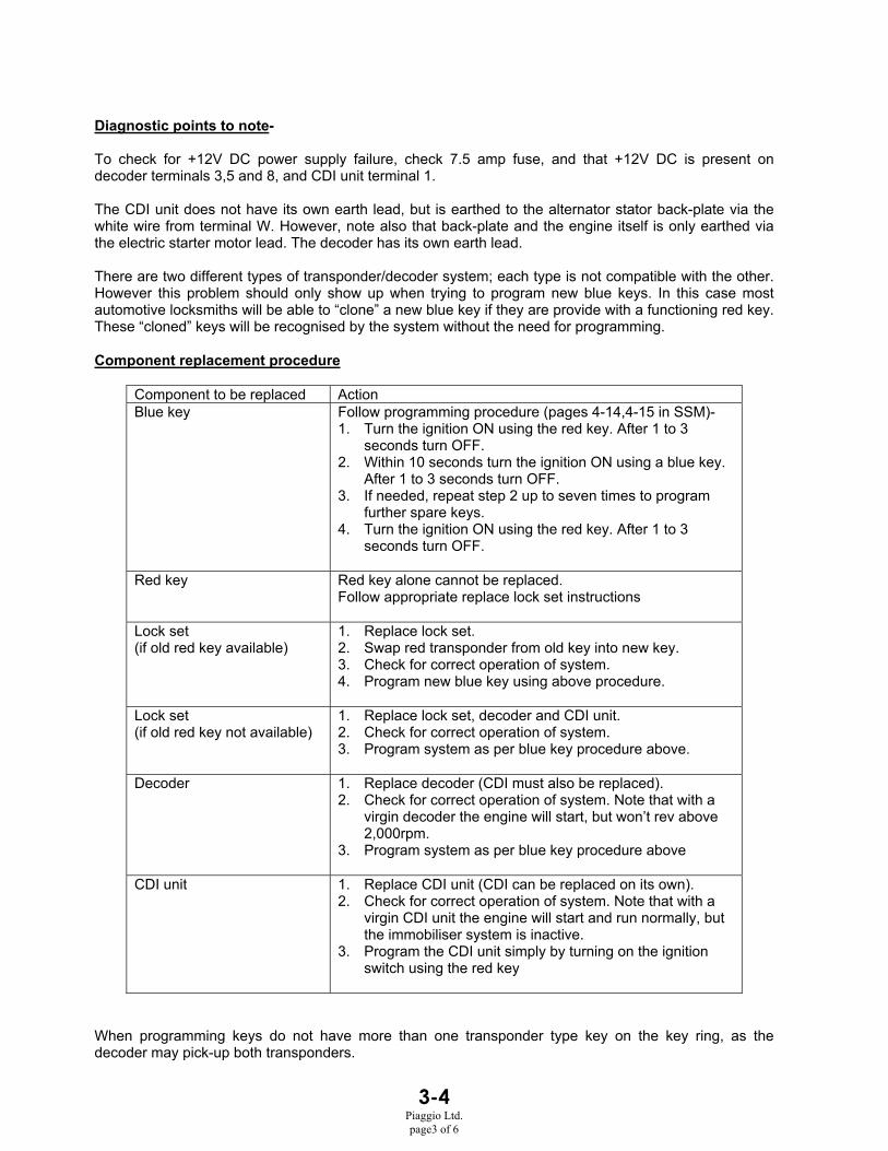
Diagnostic points to note-
To check for +12V DC power supply failure, check 7.5 amp fuse, and that +12V DC is present ondecoder terminals 3,5 and 8, and CDI unit terminal 1.
The CDI unit does not have its own earth lead, but is earthed to the alternator stator back-plate via thewhite wire from terminal W. However, note also that back-plate and the engine itself is only earthed viathe electric starter motor lead. The decoder has its own earth lead.
There are two different types of transponder/decoder system; each type is not compatible with the other.However this problem should only show up when trying to program new blue keys. In this case mostautomotive locksmiths will be able to “clone” a new blue key if they are provide with a functioning red key.These “cloned” keys will be recognised by the system without the need for programming.
Component replacement procedure
Component to be replaced ActionBlue key Follow programming procedure (pages 4-14,4-15 in SSM)-
1. Turn the ignition ON using the red key. After 1 to 3seconds turn OFF.
2. Within 10 seconds turn the ignition ON using a blue key.After 1 to 3 seconds turn OFF.
3. If needed, repeat step 2 up to seven times to programfurther spare keys.
4. Turn the ignition ON using the red key. After 1 to 3seconds turn OFF.
Red key Red key alone cannot be replaced.Follow appropriate replace lock set instructions
Lock set(if old red key available)
1. Replace lock set.2. Swap red transponder from old key into new key.3. Check for correct operation of system.4. Program new blue key using above procedure.
Lock set(if old red key not available)
1. Replace lock set, decoder and CDI unit.2. Check for correct operation of system.3. Program system as per blue key procedure above.
Decoder 1. Replace decoder (CDI must also be replaced).2. Check for correct operation of system. Note that with a
virgin decoder the engine will start, but won’t rev above2,000rpm.
3. Program system as per blue key procedure above
CDI unit 1. Replace CDI unit (CDI can be replaced on its own).2. Check for correct operation of system. Note that with a
virgin CDI unit the engine will start and run normally, butthe immobiliser system is inactive.
3. Program the CDI unit simply by turning on the ignitionswitch using the red key
When programming keys do not have more than one transponder type key on the key ring, as thedecoder may pick-up both transponders.
3-4Piaggio Ltd.page4 of 6
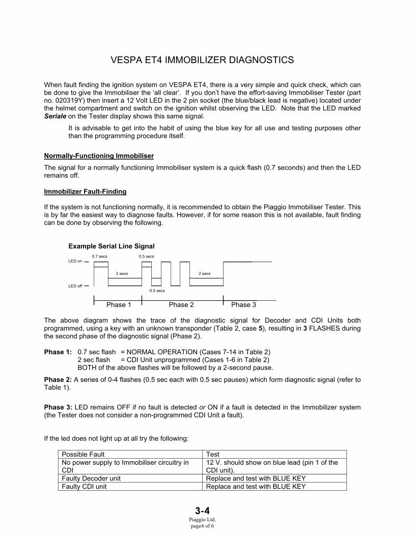
VESPA ET4 IMMOBILIZER DIAGNOSTICS
When fault finding the ignition system on VESPA ET4, there is a very simple and quick check, which canbe done to give the Immobiliser the ‘all clear’. If you don’t have the effort-saving Immobiliser Tester (partno. 020319Y) then insert a 12 Volt LED in the 2 pin socket (the blue/black lead is negative) located underthe helmet compartment and switch on the ignition whilst observing the LED. Note that the LED markedSeriale on the Tester display shows this same signal.
It is advisable to get into the habit of using the blue key for all use and testing purposes otherthan the programming procedure itself.
Normally-Functioning ImmobiliserThe signal for a normally functioning Immobiliser system is a quick flash (0.7 seconds) and then the LEDremains off.
Immobilizer Fault-Finding
If the system is not functioning normally, it is recommended to obtain the Piaggio Immobiliser Tester. Thisis by far the easiest way to diagnose faults. However, if for some reason this is not available, fault findingcan be done by observing the following.
Example Serial Line Signal0.7 secs 0.5 secs
LED on
2 secs 2 secs
LED off0.5 secs
Phase 1 Phase 2 Phase 3
The above diagram shows the trace of the diagnostic signal for Decoder and CDI Units bothprogrammed, using a key with an unknown transponder (Table 2, case 5), resulting in 3 FLASHES duringthe second phase of the diagnostic signal (Phase 2).
Phase 1: 0.7 sec flash = NORMAL OPERATION (Cases 7-14 in Table 2)2 sec flash = CDI Unit unprogrammed (Cases 1-6 in Table 2)BOTH of the above flashes will be followed by a 2-second pause.
Phase 2: A series of 0-4 flashes (0.5 sec each with 0.5 sec pauses) which form diagnostic signal (refer toTable 1).
Phase 3: LED remains OFF if no fault is detected or ON if a fault is detected in the Immobilizer system(the Tester does not consider a non-programmed CDI Unit a fault).
If the led does not light up at all try the following:
Possible Fault TestNo power supply to Immobiliser circuitry inCDI
12 V. should show on blue lead (pin 1 of theCDI unit).
Faulty Decoder unit Replace and test with BLUE KEYFaulty CDI unit Replace and test with BLUE KEY

3-4Piaggio Ltd.page5 of 6
Table 1: Immobilizer Diagnosis Chart
Phase 2LED Signal DIAGNOSIS0 FLASHES NORMAL OPERATION1 FLASH BREAK IN SERIAL LINE (ORANGE) OR DECODER EARTH (BLACK)2 FLASHES NO TRANSPONDER DETECTED - FAULTY KEY OR IMMOB. ANTENNA3 FLASHES TRANSPONDER DETECTED BUT NOT RECOGNISED BY IMMOB.4 FLASHES VIRGIN DECODER AND PROGRAMMED CDI UNIT
Table 2: Immobilizer Component Combinations and Related Diagnostic Signal
Phase 1Flash
Phase 2Signal Decoder
CDIUnit
KeyTransponder Antenna Spark Notes
1 2 sec 0 flashes V V PRESENT - ANY Y Note 1
2 2 sec 2 flashes V V ABSENT or ANY N Note 1
3 2 sec 0 flashes P V PRESENT - PROG. Y4 2 sec 2 flashes P V ANY N5 2 sec 3 flashes P V PRESENT - UNKNOWN Y6 2 sec 2 flashes P V ABSENT Y or N7 0.7 sec 4 flashes V P ANY Y Notes 1,2
8 0.7 sec 2 flashes V P ANY N9 0.7 sec 2 flashes V P ABSENT Y or N10 0.7 sec 2 flashes P P ABSENT Y or N11 0.7 sec 2 flashes P P ABSENT or UNKNOWN N12 0.7 sec 3 flashes P P PRESENT - UNKNOWN Y13 0.7 sec 2 flashes P P PRESENT - PROG. N14 0.7 sec 0 flashes P P PRESENT - PROG. Y Note 3
15 N/A 1 flash N/A N/A N/A N/A Note 4
KEY:P = UNIT PROGRAMMEDV = VIRGIN i.e. UNPROGRAMMEDY = ANTENNA FUNCTIONINGN = ANTENNA ABSENT or NOT FUNCTIONING
= IGNITION POSSIBLE= IGNITION NOT POSSIBLE
PROG. = TRANSPONDER RECOGNISED THROUGH PROGRAMMING PROCEDUREANY = KEY WITH TRANSPONDER PRESENT BUT CODE DOESN’T MATTER
NOTES:1. BLUE KEY - use for testing ignition after replacing Decoder and / or CDI Unit, otherwise you may
sacrifice perfectly good units; programs both Decoder and CDI Unit.RED KEY - only use for programming operations and ONLY when you are sure the ignition system isdelivering a satisfactory spark.The EXCEPTION to the above two points is when testing the Antenna with the RED KEY transponderflipped out, as per the ET4 Service Station Manual.
2. LIMITED TO 2000 rpm3. Normal operation with the either key4. Break in the Serial line (orange lead) or Decoder not earthed properly (black lead)

3-4Piaggio Ltd.page6 of 6

3-5Piaggio Ltd. March 1999
HEXAGON 250Charging & Ignition Circuit
• Note that the wire colour sometimes changes from one side of a conector to the other.• The choke supply is ><12 volts AC (only when the engine is running).• The fuel pump senses the engine speed and varies the supply rate accordingly.
TESTING. Green – Black: No continuity with ignition switch and kill switch to Run.Yellow - Yellow - Yellow: 0.1 – 1.0 Ώ. Stator winding.Black/Red – Black: 50 – 350 Ώ. Ignition charging coil.Green/White – Blue/Yellow: 50 – 170 Ώ. Ignition pick up coilYellow/Black – Black: 0.1 – 0.2 Ώ. HT coil primary winding.HT – Black: 3.6 – 4.6 K Ώ. HT coil secondary winding.
IGNITIONSWITCHSee Note
Contacts are:Open to
run.Closed to
stop.
Spark PlugNGK. DPR6EA-9
Blu
e / R
ed
Whi
te /
Gre
en
Blu
e / Y
ello
w
Bla
ck
Red
/ B
lack
Gre
enW
hite
/ B
lack
?
Gre
en ? ?
Pink
Gre
en /
Yel
low
Yel
low
/ B
lack
Whi
te /
Gre
en
Gre
en
Yel
low
/ B
lack
Bla
ck
Black
Fuel Pump
CDI Ignition Unit
IgnitionPick up
STATOR
IgnitionSwitch
15 AMP MAIN FUSE
CHOKEHEATER
Green
Black
Red Red
Blue / Red
Black
Yellow
RECTIFIER / REGULATOR
12 volt 12 ah.
SERVICES
Whi
te
14 – 15v @ 5000 rrpm.

3-6Piaggio Ltd. April 1999
LIBERTY 125 Charging CircuitRECTIFIER / REGULATOR WITH AN EIGHT PIN CONNECTOR
THIS IS THE ORIGINAL ENGINE NOT THE LEADER
• The charging system is basically the same as the 50 / 80cc Sferoids.1. Two completely separate circuits, AC & DC.2. DC circuit is regulated on the negative side of the alternator.
• The eight pin rectifier / regulator combines the indicator relay.• Choke unit is supplied with + 12v DC when ignition is switched on. But current can only flow
(via choke control relay contacts) when the engine is running so AC is present to pull the relay“in”. A logic circuit in the relay will not allow the choke to begin to turn off while the starterbutton is being pressed.
Grey
Blue
CHOKECONTROL
RELAY
White/ Red
Red /Black
Yellow
Grey / Blue Yellow
AC SERVICESHEAD LIGHTTAIL LIGHT
INSTRUMENT LIGHTS
STATOR
82
Rectifier / RegulatorP/N: 294878
1
White
5
IGNITIONSWITCH
DC SERVICESBRAKE LIGHT
HORNETC.
15 A FUSE
6 7
Blue /BlackBlack
ACREGULATOR
DC RECTIFIER&
REGULATOR
CHOKEUNIT
To Indicatorswitch
Battery12v 9ah
+
3 & 4Not usedGreen /
Black
12v DCfrom
starter button
7.5 AFuse
GreyWhite
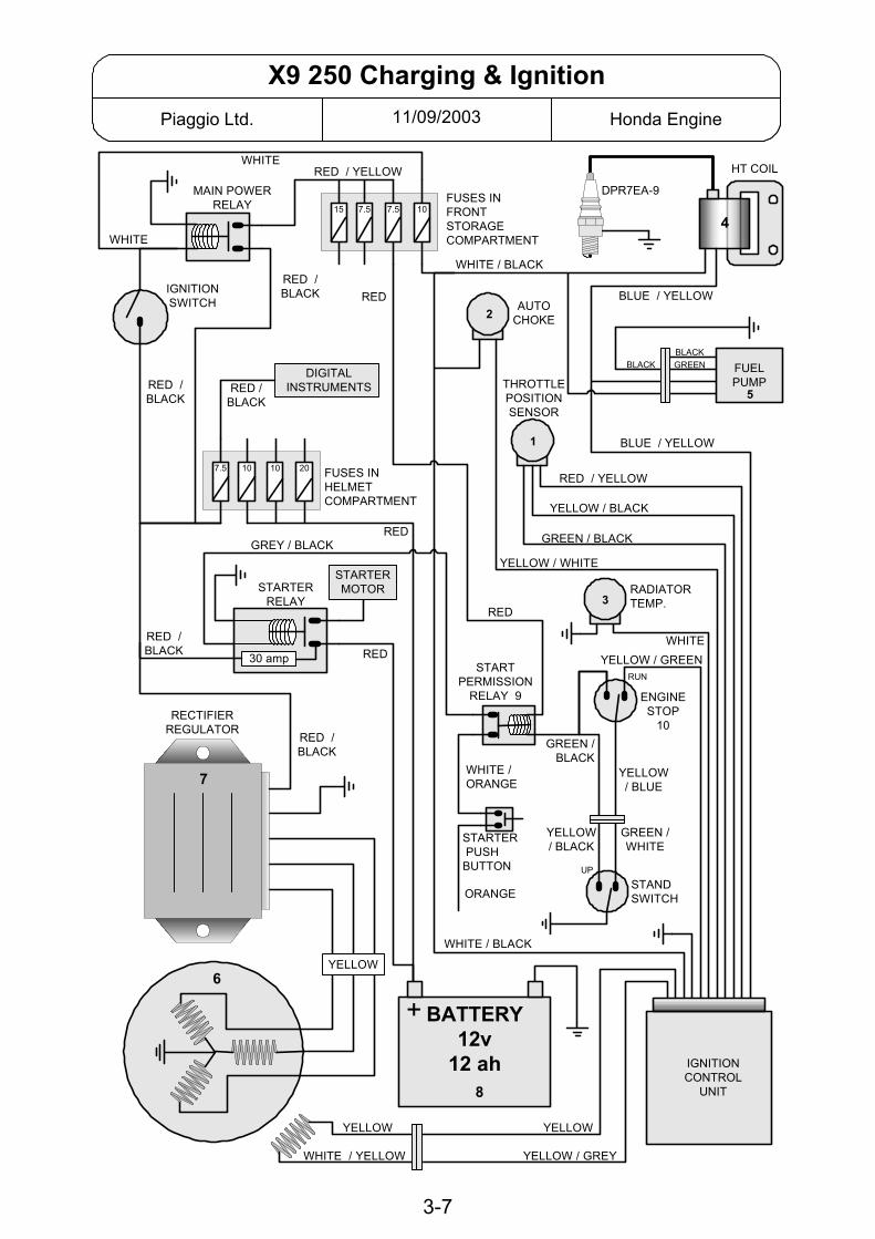
11/09/2003Piaggio Ltd. Honda Engine
X9 250 Charging & Ignition
STARTER PUSHBUTTON
DIGITALINSTRUMENTS
IGNITIONSWITCH
MAIN POWERRELAY
RECTIFIERREGULATOR
FUELPUMP
IGNITIONCONTROL
UNIT
RED /BLACK
YELLOW
RED /BLACK
RED /BLACK
RED /BLACK
WHITE / BLACK
WHITE
WHITE
WHITE / BLACK
BLUE / YELLOW
BLUE / YELLOW
RED / YELLOW
YELLOW / BLACK
GREEN / BLACK
YELLOW / WHITE
YELLOW / GREENWHITE
RADIATORTEMP.
BLACKGREENBLACK
THROTTLEPOSITIONSENSOR
AUTOCHOKE
WHITE / YELLOW
YELLOW YELLOW
GREEN /BLACK
YELLOW / GREY
DPR7EA-9FUSES INFRONTSTORAGECOMPARTMENT
RED /BLACK
RED / YELLOW
7.57.5 1015
1
2
3
4
5
STANDSWITCH
YELLOW/ BLUE
ENGINESTOP
10
RUN
UP
WHITE /ORANGE
YELLOW/ BLACK
GREEN /WHITE
RED
RED
BATTERY12v
12 ah
+6
ORANGE
GREY / BLACK
FUSES INHELMETCOMPARTMENT
7.5 201010
STARTERRELAY
STARTERMOTOR
30 amp
HT COIL
7
8
RED
RED
STARTPERMISSION
RELAY 9
3-7
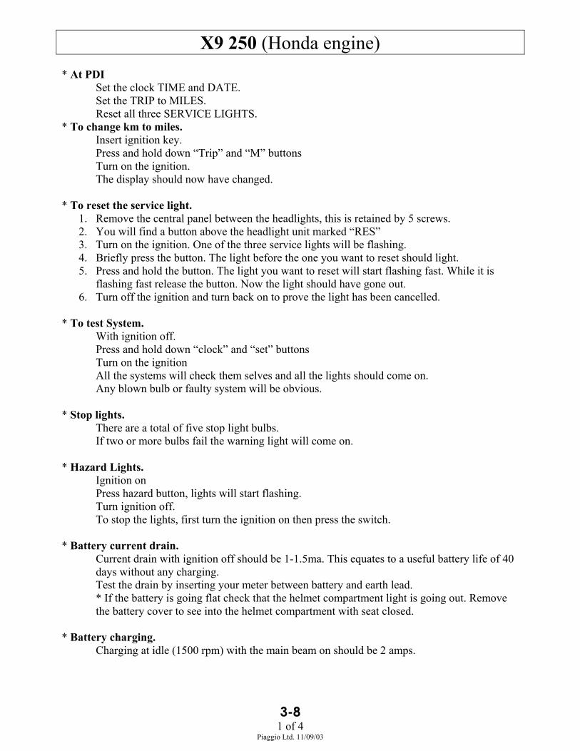
3-81 of 4
Piaggio Ltd. 11/09/03
X9 250 (Honda engine)* At PDI
Set the clock TIME and DATE.Set the TRIP to MILES.Reset all three SERVICE LIGHTS.
* To change km to miles.Insert ignition key.Press and hold down “Trip” and “M” buttonsTurn on the ignition.The display should now have changed.
* To reset the service light.1. Remove the central panel between the headlights, this is retained by 5 screws.2. You will find a button above the headlight unit marked “RES”3. Turn on the ignition. One of the three service lights will be flashing.4. Briefly press the button. The light before the one you want to reset should light.5. Press and hold the button. The light you want to reset will start flashing fast. While it is
flashing fast release the button. Now the light should have gone out.6. Turn off the ignition and turn back on to prove the light has been cancelled.
* To test System.With ignition off.Press and hold down “clock” and “set” buttonsTurn on the ignitionAll the systems will check them selves and all the lights should come on.Any blown bulb or faulty system will be obvious.
* Stop lights.There are a total of five stop light bulbs.If two or more bulbs fail the warning light will come on.
* Hazard Lights.Ignition onPress hazard button, lights will start flashing.Turn ignition off.To stop the lights, first turn the ignition on then press the switch.
* Battery current drain.Current drain with ignition off should be 1-1.5ma. This equates to a useful battery life of 40days without any charging.Test the drain by inserting your meter between battery and earth lead.* If the battery is going flat check that the helmet compartment light is going out. Removethe battery cover to see into the helmet compartment with seat closed.
* Battery charging.Charging at idle (1500 rpm) with the main beam on should be 2 amps.

3-82 of 4
Piaggio Ltd. 11/09/03
* Low fuel warning lamp.The light will only come on when it has received a continuous signal from the sender for 13seconds.
* Relays.The vehicle has five relays.Starter relay p/n 496403 has a 30 amp fuse and is in the battery compartment.Start Permission relay p/n 292332 is in the battery compartment.Two head light relays and the main power relay are all the same p/n 58002R they are allunder the front shield, headlights are central and the power relay is on the near side by theindicator.
* Headlights.The headlights are controlled by relays and each has it’s own relay so if the light fails and itis not the bulb, check the relay.
* Choke unit.Temperature sensor in the radiator can control the choke.If the temperature drops to 0 degrees C then choke will come on (no voltage to the unit)
* Honda Foresight Engine.There are two versions of the engine. The engine number will contain the letter “X” or“UU” . Piaggio use the “UU” version. Specific parts for this engine are identified by thecolour blue (blue rollers etc.)
* Valve clearance.Set Cold.Engine at TDC.Valve clearance is one division on the scale.
* Gear Box Oil LevelRemove the level screw.If no oil comes out top up until oil dripsthen wait until oil stops before re-fittingthe bolt.
* IndicatorsThe indicator relay function is part of the digital display cluster. P/n. 581413. There is noseparate relay.The wires involved are:Blue / Black - right turnGrey / BlueRed / Black - left turnNote that to operate the indicators the handlebar switch shorts the relevant wire to earth.Hazard lights work by the switch earthing the brown wire from the digital cluster.
Correct level

3-83 of 4
Piaggio Ltd. 11/09/03
* Braking system1. Three brake disks are all the same size. 200mm diameter.2. Both master cylinders are the same size.3. All brake pads are the same. p.n. 4949664. L/H front and rear calliper are the same and have 22mm pistons5. R/H front calliper has 24mm pistons.6. L/H front and rear are linked together in the following way
When left hand lever is usedUp to 8 bar pressure the rear brake only is operated.8 - 23 bar both brakes are applied.Over 23 bar the amount of pressure to the front brakes begins to decrease relative to the rear.
7. The R/H front calliper is operated by the R/H brake lever and has no connection to the otherbrakes.
* Rollers and Drive BeltRoller kit p.n. 496293. Roller min dia. = 22.5mm. Rollers are coloured blue.Drive Belt p.n. 496304 Min width = 22.3mm

3-84 of 4
Piaggio Ltd. 11/09/03
X9 250 CHARGING & IGNITIONRefer to the X9 Charging & Ignition diagram.
* Note that sometimes the wires coming from a component change colour at the connector that joinsthem to the wiring loom.* See the separate sheet for an explanation of the fuses.* Charging is three phase, fully rectified.* Ignition is digitally mapped and can not be manually adjusted.
Spark advance will be affected by:• Engine speed.• Throttle position. See # 1• Coolant temperature. See # 3
# 1. Throttle position sensor is on the carburettor.Power supply is nominally 5v dc.Resistance drops as throttle is opened.
# 2. Auto Choke. Normal wax pellet type. Defaults to “on” it is controlled by the ignitioncontrol box and can be turned on by low coolant temperature (temperature sender inradiator). If coolant temp is less than 0°c the choke will stay on.Checks.1. Remove the choke unit from the carb. Measure the length of the plunger extension.Attach the choke to a 12 volt battery, after 4-5 minutes the plunger should have extended byabout 4.5 mm.2. White/Black wire should have 12v when ignition is on.Yellow /White wire should have continuity to earth when the engine is running.
# 3. Radiator temperature sender.This is on the right hand side of the radiator. The fan switch is on the left.
# 4. HT Coil.Primary. White/black to blue/yellow = 3ΩSecondary. HT to blue/yellow = 15,000Ω (15k)Plug cap. 5,000Ω (5k)
# 5. Fuel Pump is situated under the left foot board.# 6. Stator.
Charging coils. yellow to yellow = 0.6Ω yellow to earth should give continuity.
Ignition Pick up. White/yellow to yellow = 200Ω# 7. Rectifier / Regulator. With a fully charged battery. To check the charging rate, place a
voltmeter across the battery terminals.With lights off you should have 14-15 volts at 5,000 rpm.
# 8. Battery drain with ignition off should be 1-1.5 ma. This gives a useful battery life withoutcharging (or use) of about 40 days.
#9. Start Permission Relay.Situated in the battery compartment. Contacts are normally closed. When green/black isearthed by the stand switch the contacts will open to break the start circuit..
#10. Engine Stop Switch.The yellow/green wire from the ECU must be earthed to allow the engine to run. When thestop switch is “stop” the connection to earth is broken.

11/09/2003Piaggio Ltd. Piaggio Ltd.
X9 250 FUSE EXPLANATION
FUSES IN HELMET COMPARTMENT
2 10 amp
4 7.5 amp
3 10 amp
1 20 amp
FUSES IN FRONT STORAGE COMPARTMENT
RED12v direct from
battery
RED / BLACK12v from battery
via start relay
RED / BLACKDigital Instruments
RED / BLUEHeadlight relay
WHITE / REDHeadlight relay
BLUEUnder seat light / Power socket
3
7.5a
1
15a
2
7.5a
4
10a
WHITE12v from ign.
switch
RED / YELLOW12v ign. on
via power relay
PURPLEHead Light (relay)
WHITE / BLACKIgnition
RED / GREYHorn, Side lights, Instruments
REDBrake lights, engine stop relay
3-9

22/11/01Piaggio Ltd. Piaggio Ltd.
50cc 4 stroke Charging / Ignition
PICK UP
STATOR
BLACK
BROWN
BROWN
GREY / BLUE
GREEN
WHITE
RED
BLUE / BLACK
GREY
GREY / BLUE
SUPPLY TODC SERVICES
WHITE
AC SUPPLYTO LIGHTS
BROWNRECTIFIER
REGULATOR
BLACK
WHITE
GREY
GREY / BLUE
BLACK
10A FUSE
CHAMPIONRG4HC
CDI / COILUNIT IGNITION SWITCH
TO STARTRELAY
+ BATTERY12v7ah
INDICATORSSWITCH
SUPPLY TOINDICATORS
GREY
LIGHTSON / OFFSWITCH
YELLOW / BLACK
Test 1
Only two wires come from the stator. The engine to earth connection is very important.Battery voltage at idle = 13 v (Battery charged) max will be 14.5 volts at high revs. Meter between battery neg. & pos.Battery charge at idle = 1.5 - 2 amps (lights off). max will be >5 amps at high revs with all lights on. Meter between red wire and battery pos.Test 1: Brown - earth = ~170 ohm To test pick up coil. Stator un-plugedTest 2: Black - earth = ~1 ohm To test charging coils. Stator un-plugedTest 3: Blue / Grey - earth = 25 - 35 v ac @ 2000 rpm with regulator disconnected. To test charging coils.Test 4: White - Black = ~8 M ohm. If the resistance is low it could cause the fuse to blow.
Test 4
CHOKE HEATER
LOCK
ONOFF
1 2
3
4
3-10
Test 2 Test 3

3-11Piaggio Ltd.
This information is intended only for authorised Piaggio dealers.50cc Four Stroke Restriction
Piaggio do not advocate changing the restriction on any 50cc machine that may be used on public roads.Remember that if a Piaggio, Gilera or Vespa 50cc moped is de-restricted it will be technically illegal. It will not conform toMotorcycle legislation but it did conform to Moped legislation.
The restriction is the same on all 50cc four stroke models including the LX 50 4t, Fly 50 4tand Zip 50 4t (China).The main restriction on the 50 cc four stroke engine is electronic. There is no restriction inthe exhaust pipe.
1. Make a 3mm deep cut with a hacksaw in the position shown. Then fill the slot with silicon.2. Remove the spacer washer between the front pulley halves.3. Fit carburettor main jet size #78. Part number CM 142103
If you do not de-restrict. A moped should have a top speed of 45 km/h on the flat.This engine will achieve that with an average size rider once it has run in for about 50 km.Initial acceleration is brisk but changing the main jet for that mentioned above will help itobtain top speed more easily.
CUT
Cut 3 mm deepat 45º
A C 6 + 0 0 0 0
Cut here
60 mm
38 mm