Embed Size (px)
Citation preview

Axial Pumps for Propulsion Systems
M. C. HUPPERT AND K. ROTHE
Rocketdyne A Division of North American Rockwell Corporation
A historical review of the axial-flow hydrogen pumps developed by Rocketdyne is presented. The design features and the performance data obtained during the course of these programs as well as the en- gine problems caused by the pump characteristics are discussed.
The design and development of axial-flow hydrogen pumps was initiated in 1957 by a contract awarded to Rocketdyne by Air Research and Development Command of the United States Air Force. The pump, designated Mark 9, consists of a high head inducer and six identical axial stages. This configuration was used to supply hydrogen for nuclear rocket reactor tests (December 1963 through April 1965; see ref. 1) in single- mode and dual-mode (parallel flow) feed-system configurations. The basic pump configuration with one more axial stage was used in the NASA 5-2 (LH2-LOX) rocket engine developed for the Apollo space program. During the initial development phase of the 5-2 engine, NASA sponsored the design and experimental evaluation of four axial-stage configurations designed for higher blade loading than that used in the Mark 9 staging. The results of this stage program were used to design the Mark 26 pump for use with an uprated 5-2 engine.
In response to the need for increased flow and head requirements for the evaluation of advanced reactor configuration (ref. 1) , Rocketdyne de- signed the Mark 25 axial-flow pump. The flowrate was increased by 50 percent and the head rise by 25 percent, compared to the Mark 9 pumps.
I MARK 9 TURBOPUMP
The Mark 9 turbopump consists of an inducer and six identical axial stages (fig. 1 ) . The pump has a four-bladed inducer with four splitter vanes. The six axial stages have 17 rotor blades and 42 stator blades each.
629
https://ntrs.nasa.gov/search.jsp?R=19750003129 2018-02-16T06:51:10+00:00Z

630 PUMPING MACHINERY FOR AEROSPACE APPLICATIONS
FIGURE l.-Mark 9 pump T O L O T .
The last rotor is not followed by a stator and discharges directly into a vaned volute. The pump n-as designed to run a t 34 000 rpm and produce 50 000 feet of head a t a flowate of 10 600 gal/min. The inducer produces 10 000 fect of head, and the remaining 40 000 fect is developed by the six axial stages. Mark 9 testing was initiated in 1958.
MARK 15 PUMP
The Mark 15 liquid hydrogen pump is used on the 5-2 engine in the Saturn V vehicle that launches the Apollo spacecraft to the moon. Five engines are used on the second stage and one on the third. The blade scctions of the Mark 15 pump are idcntical to thosc of the Mark 9. The Mark 15 has seven stages of axial-flow blading instead of six, as used in the Mark 9 pump. Figure 2 shows a layout of the Mark 15 turbopump. The rotating asscmbly is mounted on two bearings M ith the turbine ovcr- hung; this allows both bcarings to be located within the pump under similar load and environmental conditions. Both bearings are cooled and lubricated with liquid hydrogen. The bearing coolant liquid leaves the main passage a t the entrance to the volute and passes through a self- positioning balancc piston that nulls all the end thrust of the rotating

AXIAL P U ~ I P S FOR PROPULSION SYSTE~IS 631
FIGURE 2.-J-2 (Mark 15) fue l turbopitnap.
assembly. The flow then splits. A portion of it passes through thc rcar bearing, then through radial holes to the crnter of the shaft and out the front spinner nut; the rcmaining flow passes through the outer portion of the drum, through the front bearing and braring support, and joints the mainstream at the inducer exit. The flowratr through each bearing is approximately 10 gpm of the total balaner piston flow (45 gpm). The angular contact ball bearings are made of 440C stainless steel and have Armalon (glass-filled Teflon) cages. Bearing DN valurs are approxi- mately 1.7X10⁶ maximum. The pump must operate satisfactorily for a total of 3750 seconds with single-run times of up to 500 seconds. This life must be in addition to any ((green run” or acceptance testing required. These total life requirements are approximately 6000 seconds.
The pump has a tip diameter of 7.25 inches, runs a t 25 000 rpm, and produces 38330 feet of head a t 8580 gpm flow. The inlet and outlet pressurrs are 30 and 1247 psia, respectively. The pump absorbs 8145 horsepower under nominal conditions. Figure 3 shows a nondimensional performance map of the pump. Note that the pump has an abrupt stall, the head dropping to approximately 84 percent of the peak value; this is not too different from the nominal operating head (+=1.697). (The overall head coefficient J / of the seven-stage pump plus inducer is refer- enced to the tip diameter. The inducer head coefficient is J/lnd=0.222.) The efficiency is on the low side because of the balance piston flow losses

632 PUMPING MACHINERY FOR AEROSPACE APPLICATIONS
and the losses through the bearings. Figure 4 shows the velocity diagram for the axial-flow blading.
Cavitation performance of the Mark 15 pump a t 25 750 rpm (slightly lower than nominal) is shown in figure 5. Note that the head stays almost constant as the net positive suction head (NPSH) is reduced until the pump abruptly cavitates. Figure 6 shows the results of more than 50 such tests on 15 production pumps and 2 R&D pumps. The average line through these points is a least-squares fit. Standard deviation from the
N C 3
SI 0 7
Y
2.0 1.9
1.8
1.7
1.6
1.5 1.4
1.3
1.2
INDUCER INLET: DT = 7.80" D H ~ 2.99"
AXIAL STAGES: DT= 7.25 D"6.01
z Y- ' 0.05 0.06 0.07 0.08 0.09
INDUCER INLET FLOW COEFFICIENT, @ = CM/UT = 0.2291 @IN)
FIGURE 3.-Mark 15 pump performance.
ROTOR STATOR
I HUB
FIGURE 4.-Mark 9 ,and J-9 fuel pump axial-stage vector diagram.

AXIAL PUMPS FOR PROPULSION SYSTEMS 633
average is 14.6 feet and the 2a variation is 27.2 feet, which band encloses all the points. A scattering of points is to be expected because vapor pressure is determined from an inlet line temperature measurement and Bureau of Standards charts for parahydrogen; a temperature error of 0.1" is equivalent to a difference in vapor prcssurc of 10 feet of hydrogen. At design conditions, the suction specific speed of the pump in liquid hydrogen is 103000. The test technique used in obtaining the pump suction performance, as shown in Figures 5 and 6, neglects considerations
34 -PU
36,m k 0-
Y w,m u- 5 32, OOO
2 30, 000
m
rn 2
RMAL +PU
- a
L 0
z Y
1 I 1 50 100 150 200 250 300 350
FIGURE 5.-Typical J-I fuel pump cavitation tests in liquid hydrogen.
NPSH, FEET
7830 7900 8ooo 8100 82M1 8#x) 8400 8' SUCTION FLOW, GPM
x)
FIGURE 6.-J-2 Fuel pump suction performance in liquid hydrogen.

634 PU~IPING IIACHINERY FOR AEROSPACE APPLICATIONS
of two-phase flow a t the pump inlet. Whrn thc NPSH is equal to the duct velocity head, the duct wall static prrssure corrcsponds to the fluid vapor pressurc as indicatrd by the duct temperature measurement. The quality (vapor fraction) of the duct flow can only be determined from thc duct measurements if the fluid stagnation tcmperaturc or enthalpy is also known. Subsequent test programs in n-hieh more complete instrumrnta- tion was used indicatrd that thr pump was capable of ingesting two-phasc flo~v. The vapor fraction ingrsted for various pump inlet stagnation temperatures and flows is shown in figure 7.
STAGE LOADING ADVANCEMENT PROGRAM
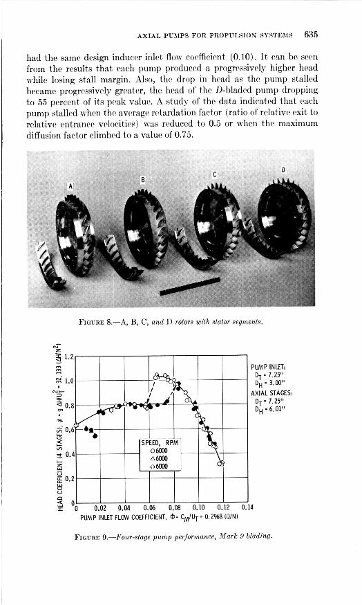
Under the sponsorship of NASA, Rockctdyne conducted an R&D effort to determine the upper limit of hydrodynamic loading that could be accepted by an axial-flow pump stagc without serious performance penalty. Four sets of blades were designed, each with a symmetrical velocity diagram a t the hub. The pumps were designated A , B, C, and D (fig. 8) with diffusion factors a t the hub of 0.58, 0.64, 0.68, and 0.72, respectively. Each pump had four stages of blading. The test results, which include volute losscs, in the air rig (ref. 2) along with a four-stage pump with Mark 9 blading arc shown in figure 9 through 13. All pumps
46
45
e44 d CT 2 43
L 42
Y a
5
z 4 41 3 a
4
II
I I I I 5 10 15 20 : i
.ET LINE VAPOR FRACTION, (I, PERCENT BY VOLUME
FIGURE 7.--hfark 15 hydrogen pump perjormance wifh two-phase inlet jlm.
AXIAL PUMPS FOR PROPULSION SYSTEMS 635
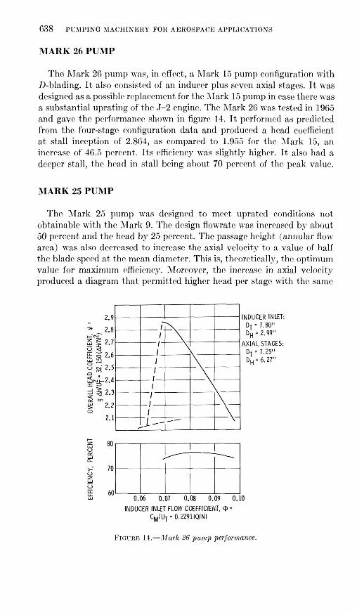
had the same design inducer inlct flow coefficient (0.10). It can be seen from the results that each pump produced a progressively higher head while losing stall margin. Also, the drop in head as the pump stalled becamc progressively greater, the head of the D-bladed pump dropping to 55 percent of its peak value. A study of the data indicated that each pump stalled when the average retardation factor (ratio of relative exit to relative entrance velocities) was reduced to 0.5 or when the maximum diffusion factor climbed to a value of 0.75.
FIGURE 8.-A, B, C, and D rolors with stator segments.
PUMP INLET: DT 7.25" DH - 3.00"
AXIAL STAGES: DT - 7.25" DH 6.01"
4 PUMP INLET FLOW COEFFICIENT, 4)- CM/UT 0.2968 (QIN)
FIGURE 9.-Four-slage pump performance, Mark 9 blading.

636 PUMPING MACHINERY FOR AEROSPACE APPLICATIONS
PUMP INLET: DT * 7.25" DH * 3.00"
DT = 7.25"
z m 1.2
d AXIAL STAGES: 4
" 1 n N k 3
a
Y Y
8 0.2 u
SPEED. RPL o m a 6500 0 6500 o m o m 0 6500 o m
z z = o 0 0.02 0.04 0.06 0.08 0.10 0.12 0.14
PUMP INLET FLOW COEFFICIENT, CM/UT = 0.2%8(Q/N)
FIGURE 10.-Four-stage pump performance, "A" blading.
A 65CQ
u 8 0.2 0 65CQ D V 6500
PUMP INLET FLOW COEFFICIENT, '$- CMIUT - 0.2%8(QIN)
'UMP INLET: DT 7.25" DH 3.00"
iXlAL STAGES: DT . 7.25" DH 6.27"
FIGURE 11 .-Four-stage pump performance, "B" blading.

AXIAL PUMPS FOR PROPULSION SYSTEMS 637
n 4, = o
. . % - I
I I I I I I I
1.0
- v1 W
I- 2 0.6 if- v)
Y Y
8 0.2 u
SPEED, RPM
0 6500
FIGURE 12.-Four-stage pump performance, "C" blading.
N
m m
z- 1.2
c
k! 0.4
V
SPEED, RPM o m 0 6513 0 7000 A6ooo 05oOo o m
PUMP INLET FLOW COEFFICIENT. CM/UT * 0.2968(Q/N)
PUMP INLET: DT 7.25" DH 3.W"
DT 7.25" DH - 6.27"
4XIAL STAGES:
'UMP INLET: DT 7.25" DH * 3.00"
DT = 7.25" OH - 6.27"
LXIAL STAGES:
. FIGURE 13.-Four-stage pump performance, "D" blading.
638 PUMPING MACHINERY FOR AEROSPACE APPLICATIONS
MARK 26 PUMP
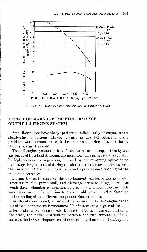
The Mark 26 pump was, in effect, a Mark 15 pump configuration with D-blading. It also consisted of an inducer plus seven axial stages. It was designed as a possible replacement for the Xark 15 pump in case there was a substantial uprating of the 5-2 engine. The Mark 26 was tcstrd in 1965 and gave the performance shown in figure 14. It performed as predicted from the four-stage configuration data and produccd a head coefficient a t stall inception of 2.864, as compared to 1.955 for the Mark 15, an increase of 46.5 percent. Its efficiency was slightly highrr. It also had a deeper stall, the head in stall being about 70 percent of the peak value.
MARK 25 PUMP
The Mark 25 pump was designed to meet uprated conditions not obtainable with the Mark 9. The design flowrate was increased by about 50 percent and the head by 25 percent. The passage height (annular flow area) was also decreased to increase the axial velocity to a value of half the blade speed a t the mean diameter. This is, theoretically, the optimum value for maximum efficiency. Moreover, the increase in axial velocity produced a diagram that permitted higher hrad per stage with the samc
2.9 INDUCER INLET: DT 7.80" DH 2.99"
AXIAL STAGES:
+ 2.8 +&-
:: g 2.6 g 2.5
a " a-~2.4
2 5 2.3
2.1
DT 7.25" DH I 6.27"
s z 2.7 WF.4
1 3
g m2.2 0
* V
E >- 0
5 - 0 : : m W ~~ 0.06 0.07 0.08 0.09 0.10
INDUCER INLET FLOW COEFFICIENT. @ = CM/UT = 0.2291(Q/N)
FIGURE 14.-Mark 26 pump performance.

AXIAL PUMPS FOR PROPULSION SYSTEMS 639
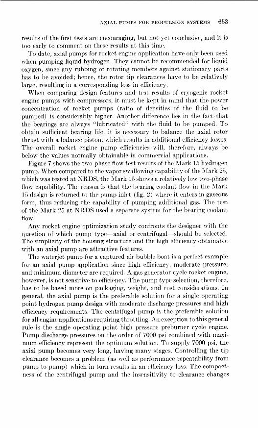
blade loading (diffusion factor). The pump was designed to give a stall margin of 25 percent; this resulted in a value of 0.63 for the retardation factor and 0.55 for the diffusion factor a t the mean diameter. The resultant velocity diagram is shown in figure 15. It was desired that the Mark 25 be capable (from the blade stress standpoint) of running a t a substantially higher speed than the Mark 9; therefore, blades with relatively large chords and cross-sectional areas were used. Only four axial stages were required. The overall pump head coefficient, however, was comparable to that of the Mark 15, as can be seen from figure 16. This pump also had a deep stall, the head falling to 60 percent of its peak value. A photograph of the Mark 25 rotor is shown in figure 17.
WATER JET PUMP
The Mark 25 design has recently been used as a model for a waterjet pump for ship propulsion. In a waterjet system, the pump efficiency is very important; therefore, a strong effort was made to obtain high efficiency. To accomplish this, the backflow through the rotor was eliminated, as was the balance piston. In addition, the stator shrouds were removed. The discharge scroll, a source of losses, was eliminated and axial stators were used in its place to provide axial flow to the nozzle and steering device. The resultant pump was tested in an accurately cali- brated water rig. The results of the test are shown in figure 18; it can be
ROTOR I
TIP
FIGURE 15.--Mark 25 axial-stage vector diagram.

640 PUMPING MACHINERY FOR AEROSPACE APPLICATIONS
B E
6 ,-- 70
0
V
60
seen from thc curve that a peak efficiency of 90 percent was obtained and that the pump head coefficient was approximately 15 percent higher than that obtained with the Mark 25 pump.
,'
INDUCER INLET: DT 7.80" DH 3.00"
AXIAL STAGES: DT - 7.26" D H - 6.23-6.29"
1.4
1.21 ' I I I I I I
INDUCER INLET FLOW COEFFICIENT, @ = C M / U ~ 0.2291(91N)
FIGURE 16.--dfark 25 p u m p performance.
FIGURE 17.-Mark 25 rotor.
AXIAL Pums FOR PROPULSION SYSTEMS 641
2.3
2.2 INDUCER INLET:
2.1
2.0 AXIAL STAGES: 1.9 DT 7.25"
DH 6.25"
DT 7.80" DH 3.00"
1.8
1.7
1.6
1.5
+
V z,
' W 70 0.08 0.09 0.10 0.11 0.12 INDUCER INLET FLOW COEFFICIENT, Cb - CM/UT 0.2291(Q/N)
FIGURE 18.-Mark 25 pump performance as a water-jet pump.
EFFECT OF MARK 15 PUMP PERFORMANCE ON THE 5-2 ENGINE SYSTEM
Axial-flow pumps have always performed satisfactorily on engines undcr steady-state conditions. However, early in the 5-2 program, many problems were encountered with the proper sequencing of events during the engine start transient.
The 5-2 engine system consists of dual series turbopumps driven by hot gas supplied by a bootstrapping gas generator. The initial start is supplied by high-pressure hydrogen gas, followed by bootstrapping operation to mainstage. Engine control during the start transient is accomplished with the use of a LOX turbine bypass valve and a programmed opening for the main oxidizer valve.
During the early stage of the development, excessive gas generator temperature, fuel pump stall, and discharge pressure decay, as well as rough thrust chamber combustion at very low chamber pressure levels was experienced. The solution to these problems required a thorough understanding of the different component characteristics.
As already mentioned, an interesting feature of the 5-2 engine is the use of two independent turbopumps. This introduces a degree of freedom in terms of relative pump speeds. During the hydrogen gas spin portion of the start, the power distribution between the two turbines tends to increase the LOX turbopump speed more rapidly than the fuel turbopump

642 PUMPING MACHINERY FOR AEROSPACE APPLICATIONS
speed. After completion of the hydrogen gas spin, the combustion in the gas generator is initiated and the power distribution starts favoring the fuel turbine. During the gas spin portion, the higher LOX pump speed results in an increased LOX flow that produces a higher head demand on the fuel pump and tends to drive the fuel pump toward stall. To com- pensate for this, it was necessary to use a LOX turbine gas bypass system, which allows a portion of the spin gases to bypass the LOX turbine and reduce its speed to be compatible with the fuel turbopump. During engine thrust buildup, the fuel pump operating point must be kept away from the stall line throughout the entire start. It is Rocketdyne’s practice to con- sider any start during which the stall line is crossed as a failure even though no hardware damage may result. The start sequence which has evolved is as follows:
The main fuel valve is opened to allow a small amount of fuel to flow through the pump and thrust chamber to ensure that liquid hydrogen is in the pump a t the time the spin gases are released.
The gas spin valve is opened and the fuel pump is accelerated to approximately 11 000 rpm and the LOX pump to 4500 rpm.
The main LOX valve opens approximately 14 degrees thus allow- ing the LOX dome to be filled and main propellant ignition established.
The gas generator valves open and engine bootstrapping begins. The turbopumps are continuously accelerated and the main LOX
(1)
(2)
(3)
(4) (5)
valve gradually ramps to full open.
Figure 19 shows a typical engine start superimposed on a Mark 15 fuel pump map. The entire length of the line is traversed in about 23 seconds. It can be seen that during the spin bottle blowdown the pump moves toward the stall line and then loops away from it. Also, when the dome of the thrust chamber is primed with LOX and chamber ignition occurs, there is another movement toward the stall line. Finally, the movement of the main oxidizer valve (RIOV) brings the path closer to stall.
DESIGN CONSIDERATIONS
The axial pump design process is dil*ect.ed to achieve a configuration that will satisfy design requirements and will also operate within the con- straints imposed by other components of the turbopump assembly. Thus, the pump design cannot be divorced from the design of components such as the drive turbine, inducer, bearings, and seals.
The hydrodynamic design consists of the proper selection of the fluid velocity diagrams and the blading. The design must assure the required fluid turning with a minimum of pressure losses. Structural adequacy is achieved by maintaining the operating stresses within the limits of the

AXIAL PUMPS FOR PROPULSION SYSTEMS 643
D FLOW, GPM x 10-3
FIGURE 19.-Pump start transient with J-2 engine.
materials used. Major areas of conccrn include fatigue failurcs of the blading and excrssive elastic deflections of the housing and rotor as- semblies rather than Rlajor areas of concern include fatigue failure in the blading housing and rotor deflection.
The dynamic behavior of the turbopump rotor has received attention in rocket engine design and development programs. In particular, the critical speeds associated with bearing stiffness have resulted in develop- ment problems. The use of duplex ball bearings or roller bearings to achieve turbopump operation free of shaft critical speeds is the safest design policy.
Stage Hydrodynamic Design
The procedure used in the hydrodynamic design of axial pumps has generally followed axial-flow compressor design practice (ref. 3) . The

644 PUMPING MACHINERY FOR AEROSPACE APPLICATIONS
three-dimensional flow problem is approximated by assuming axisym- metric flow. Radial variations in flow are approximated from continuity, energy addition, and radial equilibrium considerations consistent with the axisymmetric flow assumption. Flow losses are estimated from cascade data and flow loss correlations, such as those prescnted in references 4 and 5.
The diffusion factor has been used successfully (ref. 3) as a measure of blade loading and as a correlation parameter for blade profile loss data. For a symmetrical velocity diagram, the diffusion factor (DF) is related to the ideal head coefficient, +%, and flow coefficient, 4, as follows:
This relationship is shown graphically in figure 20. Rocketdyne experience
1.0
0.9
0.8
0.7
* s- 0.6 u
0.5
Y - Y Y
0
n
9 0.4
0.3
0.2
0.1
FIGURE 20.--E$ect offlow coefi- o cient on head coeficient for con- stant diffusion factor.
0.2 0.4 0.6 0.8 1.0 1.2 FLOW COEFFICIENT, d

AXIAL PUMPS FOR PROPULSION SYSTEMS 645
with six axial-stage designs has indicated that stagc stall occurs a t a diffusion factor value of approximately 0.75. The diffusion factor, how- ever, is determined from the vector diagrams rather than the blade surface velocity distribution which determinrs boundary layer growth and separation. Consequently, any relationship betwrcn diffusion factor and stall could not apply to all bladc profile typcs. Generally spraking, how- ever, the larger the design diffusion factor, the smaller the stall margin.
Blade Profiles
Research and development of blading for axial-flow compressors has produced considerable data on so-called standard profiles. These include the NACA G5-serics, British C-series, and double-circular-arc profiles. Nonstandard profile shapes with the maximum thickness moved bryond the 50-percent chord point may have reduced maximum surfacc velocity. Such shapes have a lower cavitation number and arc particularly ad- vantageous for high-solidity applications (rrf. 6 ) . Table I show thr pro- files and drsign parameters used in thcsc four pump designs. The ;\[ark 9 and Mark 25 pumps incorporated nonstandard blading. The blading was designed by an iterativc procrss in which the bladc surface velocities were computed by the stream filament theory discussed in reference 3. The gen- eral criterion was that the suction surfacc vrlocity should riot exceed 1.2 times the relative inlet velocity. ,4 sample profilr is shown in figure 21, and its computed surface velocity in figure 22. A design incidence angle of zero was used; the deviation angle was estimated by thc procedure pre- sented in reference 3. The A , B, C, and D werc the doublr-circular-arc- typr blading. In genrral, thr effort rrquircd t o drsign thr nonstandard profile is deemed to be worthwhile.
ACKNOWLEDGMENT
The data concerning the dcvelopmcnt of the first axial pump used in rocket engine systems were made available by the Power Systems Divi- sions of North American Rockwell, who pioneered this pump type under the sponsorship of NASA.
The authors wish to express their thanks to the engineers who partici- pated in this development. Special acknowledgment is given to Dr. George Wislicenus who, as consultant, contributed substantially to the success of these programs.

646 PUMPING MACHINERY FOR AEROSPACE APPLICATIONS
c i n ? r - m a m
Q , m
e o m - f c ? ?
c i ? 3 0 0 w m
m o o
o r - E ? ? e m
W c ? ? z ; ; s
9 9 2 %
? ? m m w w
Y 9 2 %
m m w 0 0 ? ,9
6 s 9 9 0 0
0 2 s . . 0 0
w - 2 -
a 5 u1
I -:-
a
5 rn F ? 0 0
m - f o m
0 0 ? ?

AXIAL PUMPS FOR PROPULSION SYSTEMS 647
m m t : ? m a , m m
m m
m w m m Y o 9
5 r m m m m
9 1 m e m m
' ? 1 w e m m
? ? e m P a m
? - ! a , w m e
- ! 9 m w N M
- 3 . . r - m m e
9 9 w m e *
9 0 9 3 %
3
1 r 3 3
a m 9 0 ! 3 3
w m ? @ ? 3 3
a, @ ? ?
m o c ? r 3 3
N * m m 9 9
e e m m 9 9
m a , w m 9 9
0 0 0 0 0 0
N W 2 2 . . 0 0
e m % 3 0 0
N 2 2 . . 0 0
2 5 : 0 9 0 9 0 0
w ' c r M r -
0 0 0 9 0 9
a , * a m @! c? 3 3
2 m ? ? 0 0
8 % = ! ? 0 0
m u 5 r-
0 0 8 0 9
r- w % ? " ! 3 3
a u n

648 PUMPING MACHINERY FOR AEROSPACE APPLICATIONS
74.50 ,FLUID
FIGVRE: 21.-Jlark 25 rotor blade, hub.
I BLADE SURFACE LENGTH, S
FIGURE 22.-Mark 25 blade surface velocity ratio (rotor hub).

AXIAL pums FOR PROPULSION SYSTEMS 649
LIST OF SYMBOLS
C
D F DH DN
DT 9 AH N Q
C M
S
UT
4
c u
Blade chord length, inches Meridional velocity, ft/sec Diffusion factor (defined in text) Hub diameter, inches Bearing speed parameter, bore diameter (mm) X rotational
Tip diameter, inches Gravitational constant, ft/sec2 Pump developed head, ft-lb/lb Pump rotational speed, rpm Pump volumetric flow, gpm Blade spacing, inches Tangential velocity at tip, ft/scc Flow coefficient, defined as C M / UT Solidity, defined as C/s Head coefficient, defined as gAH/ UT^
speed (rpm)
REFERENCES
1. GUNN, S. V., AND C. DUNN, Feed Systems and Nozzles for Phoebus Reactor
2. KING, J. A., Testing Pumps in Air. Trans. A S M E , J . Eng. Power, Yer. A, Vol. 90,
3. Aerodynamic Design oj Azial Flow Compressors, NASA SP-36, 1965. 4. Axial Cascade Technology and Application to Flow Path Designs; Part 1, Axial
Cascade Technology. Trans. A S M E , J . Eng. Power, 1968. 5. LIEFJLEIN, S., Loss and Stall Analysis of Compressor Cascades. Trans. A S M E ,
J . Basic Eng., Ser. D , Vol. 81, No. 3, 1959. 6. TAYLOR, W. E., T. H. MURRIN, AND R. M. CoLoMno, Systematic Two-Dimensional
Cascade Tests. Multiple Arc Hydrofoils, NASA CR-72499, Vol. 2.
Experiments. J . Spacecrajt Rockets, Vol. 6, No. 7, 1969, pp. 769-777.
NO. 2, 1968, pp. 97-105.

650 PUMPING RIACHINERY FOR AEROSPACE APPLICATIONS
DISCUSSION
G. I<. SEROVY (Iowa State University) : Reference 8 is given as the source of some of the design procedures used for all of the Rocketdyne pumps. It would keep the record clear if some added comments could be made about both the velocity diagram computations and the selection of blading.
Were the rotors for these stages all designed for a constant actual or a constant ideal head rise along the radius (hub to tip) or was some other variation of energy transfrr specified? Is the incidence angle defined with reference to the blade mean camber line or with respect to the blade suction surface (as in some compressor applications) ? Did the deviation angles estimated include any arbitrary corrections, such as the 8c -82 -~ given in reference 3, or were the two-dimensional correlations used without correction? CouId the authors give the average rotor and stator tip clear- ances used, and could they say something about the axial spacings between blade rows?
These questions are asked not in a critical sense, but mainly to get some significant data on record. A number of years ago, many of us in reporting experimental results on axial-flow compressors failed to give or record important design data. As a consequence, the value of the experiments has been somewhat diminished. The data developed in the Rocketdyne work should be supported by the most complete design information that is possible to obtain.
L. H. SMITH (General Electric Co.) : I was interested in your comment that the hub tip diameter ratio of 0.83 was high enough to be of concern to you; whereas, in the axial-flow compressor field, we go abovr Y ~ o in our rear stages without feeling that we suffer a grtiat deal in efficiency so long as the ratio of clearance to blade height is kept small. You mentioned also in your comments that you recognized clearance was quite important, and I wondered if you would be good enough to tell us what the clearance levels mere in these pumps that you had given this data for. One further comment: The Mark 25 had very impressive efficiency; it was almost 90 percent in a flow coefficient that mas just over 3{0. I looked a t the photograph of the rotor, and it appears that the stator vanes have shroud a t their inner diameter; a t least there appear to be recesses in the rotor drum. Was this, in fact, the case? I presume these were well sealed if this was the case.

AXIAL PUMPS FOR PROPULSION SYSTEMS 651
F. GILMAN (Worthington Corp.) : Have you given any thought to the improvement in range? For example, the Westinghouse Company was able to completely suppress the disturbance which came from stall in their blowers. This mas done by putting a divider betwrrn the flow which approached the outer tips of the impeller and that which approached further in. More recrntly, Worthington Company has been able to cut out the stall on their axial-flow blower by merely putting holes in the shroud a t the proper places. I think there are many ways by which the stall range of axial-flow machines could be improved.
HUPPERT AND ROTHE (authors) : The authors agree wholrhcartrdly with RIr. Serovy’s comment that the value of exprrimental data is en- hanced when supported by design information.
The rotors used in the experimental study were designed for a constant ideal head rise from hub to tip. The Mark 1.5 inducer, however, had radial blade elements, while the Nark 25 inducer is designed for constant head. The incidence angle is defined with reference to thr mean camber angle and, for the deviation angle, Carter’s rule without corrrctions was used. The Mark 25 pump was designed using Howell’s modification of Carter’s rule as presented in reference D-1.
During the development phase of the Mark 15 pump, which has a hub-to-tip ratio of 0.83 for all seven stages, it was observed that, due to tip clearance variations, pump head and efficiency varird from pump to pump. These variations had to be reduced in order to satisfy thr engine specifications. Therefore, the following procedure was rstablishcd : The pump was installed in the componrnt test facility which is capable of oprrating a t speeds higher than design speed while puinping liquid hydrogen. The tolerances of the rotor, stator, and housing are throretically set such that when running with about 10-percent overspeed the rotor blade tips “kiss” the housing. This results in a close clearance under design point operating speed conditions, and performance repeatability from pump to pump is assured. Taking into account eccentricity, the resulting rotor tip running clearance tolerances are between 0.0041 and 0.0196, and the radial stator tip running clearance lies between 0.033 and 0.0177. Notice that the stator clearance is largrr; no “run-in” is required to assure performance repeatability, as was confirmrd by experi- mental studies during which the stator clearance was changed.
The axial blade spacing was set to 0.0785+,0 ::: following the rotor and 0.1199f:,::i following the stator. These spacings were set by thc drsire to obtain the shortest and lightest pump. No trsts were conducted to assess the effect of different spacings.
The Mark 25 pump has stator shrouds, as correctly observed by Mr. Smith. In this case shrouds were used to preclude blade failure due to fatigue combined with the relatively high blade hydraulic loading. The

652 PUMPING MACHINERY FOR AEROSPACE APPLICATIONS
clearance between the shrouds and the rotor drum is 0 . 0 1 7 t E ~ ~ ~ on the diameter. The overall efficiency obtained is 78 percent (fig. 17). This efficiency includes volute and axial thrust balance piston losses.
Later, the Mark 2.5 was used as the basis for a waterjet pump. Since the efficiency of this pump was of prime importance for the planned application, the pump was redesigned to minimize all parasitic losses ; the shrouds were removed and a smooth cylindrical rotor drum was used. The axial thrust balance piston necessary when operating with hydrogen- lubricated bearings was eliminated, and oil-lubricated bearings carrying the axial rotor loads were installed. Furthermore, closely controlled seals were used to minimize the leakage losses, and the volute was eliminated and replaced by a nozzle which converted the pump pressure mrasurcd at the last rotor exit into velocity. The result of thew changrs was that a peak efficiency of 90 percent measured at the csit of the last rotor was reached (fig. 19). JIr. Smith pointed out that in asial-flow compressors, a hub-to-tip ratio of 0.9 or higher is used in the rear stages without a sub- stantial efficiency loss as long as the clearance-to-blade height ratio is kept small. We agree and the results of the waterjet pump, which has a hub-to-tip ratio of 0.85, confirm this. It must, however, be krpt in mind that, when pumping liquid, all stages have the same hub-to-tip ratio and it is rather difficult to maintain close clearances with high-horsepowrr, high-speed pumps when pumping cryogenics, as demonstrated by the elaborate procedure which was used for the Mark 13 production. At this point, we would like to correct a misunderstanding. In all pump performance graphs in the paper the flow coefficient is referenced to the pump inlet (that is, to the inducer inlet), while the repeating asial stages are designed for a higher flow coefficient (fig. 4 and fig. 16).
Figure 4, representing the Mark 1.5 axial stage vector diagram, show a lower flow coefficient than figure 16 which represents the Mark 2.5 The reason for the selection of the lower flow coefficient is that 12 years ago, when the Mark 1.5 was designed, we were concerned about first axial stage stator cavitation and the possibility that high hub-to-tip ratios might impair the obtainable efficiency. Therefore, an asymmetrical vector diagram was selected with low stator velocities and a relatively low axial through-flow velocity to obtain maximum bladr height. Experi- ence later showed that this concern was not justified, which led to the design of the Mark 2.5.
Mr. Gilman’s suggestion to widen the operating range by suppressing the disturbance generated by pump stall is appreciatrd. Thc importance of this idea is especially evident in light of the facts illustrated in figure 19. During our experimental studies, we found that the tip clearance was critical to stall margin. The smaller the clearance the greater the margin. Currently, Rocketdyne is working on improvement in range for multi- stage axial pumps with constant blade height on a research basis. The
AXIAL PU3IPS FOR PROPULSION SYSTEMS 653
results of the first tests are encouraging, but not yet conclusive, and it is too early to comment on these results a t this time.
To date, axial pumps for rocket enginr application have only been used when pumping liquid hydrogen. They cannot be recommended for liquid oxygen, since any rubbing of rotating members against stationary parts has to be avoided; hence, the rotor tip clearances have to be relatively large, resulting in a corresponding loss in efficiency.
When comparing design features and test results of cryogenic rocket engine pumps with compressors, i t must bc kept in mind that the power concentration of rocket pumps (ratio of densities of the fluid to be pumped) is considerably higher. Another difference. lies in the fact. that the bearings are always “lubricated” with the fluid to br pumped. To obtain sufficient bearing life, it is necessary to balance the axial rotor thrust with a balance piston, which results in additional efficiency losses. The overall rocket engine pump efficiencirs will, therefor?, always be below the values normally obtainablc in commercial applicc ‘1 t’ ions.
Figure 7 shows the two-phase flow test results of the Mark 15 hydrogen pump. When compared to the vapor swallowing capability of the Mark 25, which was tested a t NRDS, the Mark 13 shows a relatively low two-phase flow capability. The reason is that the bearing coolant flow in the Mark 15 design is returned to the pump inlet (fig. 2) where it enters in gaseous form, thus reducing the capability of pumping additional gas. The test of the Mark 25 a t NRDS used a separate system for the bearing coolant flO\Y.
Any rocket engine optimization study confronts the designer with the question of which pump type-axial or centrifugal-should be selected. The simplicity of the housing structure. and the high efficiency obtainable with an axial pump are attractive features.
The waterjet pump for a captured air bubble boat is a perfect example for an axial pump application since high efficiency, moderate pressure, and minimum diameter are required. A gas generator cycle rocket engine, however, is not sensitive to efficiency. The pump type selection, therefore, has to be based more on packaging, weight, and cost considerations. In general, the axial pump is the preferable solution for a single operating point hydrogen pump design with moderate discharge pressures and high efficiency requirements. The centrifugal pump is the preferable solution for all engine applications requiring throttling. An cxcrption to this general rule is the single operating point high pressure prcburner cycle engine. Pump discharge pressures on the order of 7000 psi combined with maxi- mum efficiency represent the optimum solution. To supply 7000 psi, the axial pump becomes very long, having many stages. Controlling the tip clearance becomes a problem (as mrll as performance repeatability from pump to pump) which in turn results in an efficiency loss. The compact- ness of the centrifugal pump and the insensitivity to clearance changes

654 PUMPING MACHINERY FOR AEROSPACE APPLICATIONS
when shrouded impellers are used makes this pump the superior solution. In conclusion, the authors wish to thank the discussors for their con-
sideration and thoughtful comments which form an appreciated supple- ment to the paper.
REFERENCES
D-1. HORLOK, T. H., Axial Flow Compressors. Fluid Mechanics and Thermody- namics, 1958, p. 58.