Embed Size (px)
Citation preview

1 INTRODUCTION
Deep foundation design is capacity-centric in that designers and engineers primarily look to establish a working foundation type and size that will satisfy given construction and loading requirements. The loaded behavior or settlement analysis of deep foundations is not immediately examined in many deep foundation designs. The tendency to ignore settlement analysis of deep foundations occurs often as the analysis can be rigorous and most deep foundations are put forth as settlement mitigation techniques with displacements that are anticipated to be minimal and are not expected to cause damage to structures. Analysis of the loaded behavior of deep foundations can be performed using a number of techniques. Raft methods incorporating strain influence and raft methods incorporating elastic shortening are the most common approaches used to determine the load-displacement-capacity response of axially loaded deep foundations. The purpose of this paper is to present a case study that details the load-displacement-capacity response of augercast concrete piles subject to traditional top-down static axial compressive load tests. The subject project took place in Norfolk, Virginia on the campus of Old Dominion University. The project involved the construction of a 2,800 square meter, one and two-story addition to the existing Perry Library. The addition is referred to as the Old Dominion University Student Success Center. The addition was constructed using a cast-in-place concrete exterior with a green roof. Column loads of 2340 kN were anticipated for the new structure under service conditions. The project site was investigated by 7 piezocone (CPTu) soundings and one seismic piezocone (SCPTu) sounding performed to a depth of 25 meters below the existing ground surface. Augercast concrete piles measuring 405 mm in diameter were selected as a low noise, low vibration foundation option for use in the construction of the addition. Five static load tests were conducted as part of the pile installation and monitoring program to verify the in-situ capacity of the installed augercast piles. The results of the load tests were compared to the load-displacement-capacity analysis conducted using easily programmable raft based strain influence methods (Poulos’ elastic continuum) incorporating nonlinear soil stiffness to good agreement.
Axial pile capacity within an elastic continuum framework in Virginia’s Coastal Plain
C.L. Cox, P.E. & S.A. Barnhill, P.E. GeoEnvironmental Resources, Virginia Beach, Virginia, USA
ABSTRACT: This paper presents a case study of the load-displacement-capacity response of augercast concrete piles installed in layered soils of Virginia’s Coastal Plain within an elastic continuum framework. Using this approach, a nonlinear representation of load-displacement-capacity response under axial compressive loading is examined. Augercast concrete piles measuring 405 mm in diameter were subject to traditional top-down static axial compressive load tests. Pile capacities were directly calculated using Laboratoire Central des Ponts et Chaussées (LCPC) methods and Piezocone Test (CPTu) data. Analysis using elastic continuum theory calculated theoretical pile displacements. The measured pile displacements from load testing were in close agreement with the calculated theoretical displacements using elastic methods. Theoretical displacements and measured displacements from load testing were compared using both directly measured shear wave velocities from Seismic Piezocone Testing (SCPTu) and correlated shear wave velocities.
2 DISPLACEMENT ANALYSIS OF PILE FOUNDATIONS
Axial load-displacement response of piles using a raft based approach incorporating strain influence (Poulos & Davis, 1980) will be addressed in this case study. For piles in layered soils, a Randolph-type soil model can be used to calculate pile toe displacements and load transfer to the pile toe (Mayne, 2009). Where displacement of a given pile, wt, is given as:
𝑤! =𝑃! ∗ 𝐼!𝑑 ∗ 𝐸!
(1)
where wt = displacement; Pt = applied axial force; d = pile diameter; Ip = displacement influence factor and Es = elastic modulus of the soil. Where the closed form displacement influence factor (Randolph &Wroth, 1978, 1979) Ip for a two layered system is given as:
𝐼! =1
𝐸!𝐸!"
∗ 1(1 − 𝜈)! +
𝜋(1 + 𝜈) ∗
(𝐿 𝑑)Ϛ!
(2)
where Ϛ! = ln[ 5 ∗ (𝐿 𝑑) 𝐸𝑏𝐸𝑆𝐿
𝜌! ∗ 1− 𝜈 − 0.1 + 0.1 ]
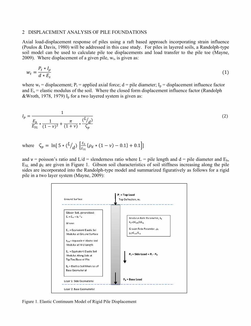
and ν = poisson’s ratio and L/d = slenderness ratio where L = pile length and d = pile diameter and Eb, ESL and ρE are given in Figure 1. Gibson soil characteristics of soil stiffness increasing along the pile sides are incorporated into the Randolph-type model and summarized figuratively as follows for a rigid pile in a two layer system (Mayne, 2009):
Figure 1. Elastic Continuum Model of Rigid Pile Displacement

3 NONLINEAR SOIL STIFFNESS
Under applied shear stress, a given material will exhibit deformation and distortion. Shear modulus (or Modulus of Rigidity), G, is a measure relating shear stress to shear strain. 𝐺 =
𝛥𝜏!𝛥𝛾!
3
where τs = shear stress and γs = shear strain.
For small strains, the shear modulus G is related to Young’s Modulus, E, as follows (Mayne, 2009): 𝐸 = 2 ∗ 𝐺 1 + ν 4
where ν, poisson’s ratio, represents the elastic character of a material:
ν = −𝜀!"#𝜀!"#$
(5)
where εlat = applied strain in the lateral direction and εlong = applied strain in the longitudinal direction. Gmax, the fundamental small strain soil stiffness at initial loading is: 𝐺!"# = 𝐺! = 𝜌! ∗ 𝑉!! (6)
where ρT = total soil mass density and Vs = shear wave velocity.
From Eq. 6 it can also be said for small strains, the initial Elastic Modulus Emax can be represented as:
𝐸!"# = 2 ∗ 𝐺!"# (1 + ν) (7) When applied loads produce strains that exceed the small strain limit of γs < 10-4, values of shear modulus G must utilize shear modulus reduction curves to dampen and obtain the appropriate value of G as the modulus softens with increased loading to model the nonlinear behavior of soils subject to increased stresses. A commonly used modulus reduction approach (Fahey, 1998) provides modulus reduction curves G/Gmax in terms of mobilized shear stress τ/τmax. The mobilized shear stress τ/τmax can also be represented as the reciprocal of Factor of Safety (Mayne, 2009)
𝜏𝜏!"#
=𝜏!""𝜏!"#
= 𝜏!""
𝐴𝜏!"#
𝐴=𝑃!""𝑃!"#
=1𝐹𝑆 (8)
where τapp = applied stress. Then, Fahey’s modulus reduction factor RF can be written as:
RF =𝐺
𝐺!"#= 1 − 𝜏 𝜏!"#
! = 1 − 1𝐹𝑆
! (9)
where g = 0.3 ± 0.1 for most soils exclusive of cemented, sensitive, highly structured materials (Mayne, 2009).

And the reduction for E/Emax can be assumed to follow a modified hyperbolic behavior of G/Gmax (Lee, et al., 2004). An expanded reduction scheme for E/Emax is provided by Lehane and Fahey (2002).
4 AXIAL CAPACITY OF AUGERCAST PILES
The axial capacity of augercast piles can be calculated using a number of analytical methods. Examples of indirect (rational) methods include well known alpha and beta methods in combination with conventional bearing capacity equations used to calculate side friction and end bearing, respectively. Direct CPT methods include Laboratoire Central des Ponts et Chaussées (LCPC), Imperial College Procedures (ICP), Norwegian Geotechnical Institute (NGI) method, Kajima Technical Research Institute (KTRI) method or Takesue method and the Unicode method. This case study utilizes the LCPC approach in calculating the axial capacity of 405 mm diameter augercast piles at the project site. The LCPC approach was chosen due to its reliability (albeit often conservative values) in local soils. The LCPC approach is based on 197 pile load and extraction tests in a wide range of soil types with a variety of pile types, lending to its acceptance as a valid method in a multitude of installations (Robertson and Cabal, 2012). The pile side friction and end bearing values are both calculated using tip resistance measurements (qc) taken from the CPT and do not incorporate friction sleeve measurements. The method can be calculated with relative ease using a spreadsheet for tabulations. Generally, the pile side friction, fp, is given as: f! =
𝑞!𝛼!"#"
10
where qc= measured tip resistance and αLCPC = LCPC method friction coefficient. End bearing, qb, is represented by: q! = 𝑘! ∗ 𝑞!" 11 where kc = LCPC end bearing coefficient based on pile and soil type and qca = average equivalent tip resistance. Complete details of the method and values for αLCPC, kc and qca can be found in the originating publication of Bustamante and Gianeselli (1982). 5 STATIC LOAD TEST
The working capacity of installed piles is most effectively determined using in place (field) load testing. Piles are loaded and corresponding displacements are then directly measured to evaluate pile performance. Load testing types include static, statnamic and dynamic testing. Static testing is the most fundamental of the testing types and involves the placement of a predetermined test load representing service, strength and/or failure conditions at the pile head. Compressive, tensile and/or lateral loading and behavior can be monitored with static load testing. The pile is loaded and then monitored. Displacements of the pile head are measured using dial gages as the pile is incrementally loaded and/or unloaded. Each load is held and monitored for a specific amount or time or until a specific amount of movement has been recorded. Static load testing most often uses a loading hydraulic jack operating against a reaction beam or a jack operating against a reaction mass or kentledge/dead weight to provide the specified test load. The pile and test loading system is restrained using a reaction frame composed of beams and piles. The results of field load testing are then used to determine the working capacity of tested piles.

6 CASE STUDY: OLD DOMINION UNIVERSITY
The construction of the 2,800 square meter one and two-story Student Success Center addition to the Perry Library at Old Dominion University in Norfolk, VA involved the installation of sixty-eight 405 mm cast-in-place (augercast) concrete piles. The test pile program for the project called for five 405 mm augercast piles to be installed and for static load tests to be performed on each of the test piles. The site was explored by 8 piezocone penetration test (CPTu) soundings pushed to depths of about 25 m below the ground surface. Seismic shear wave velocity testing (SCPTu) was conducted at one of the CPTu sounding locations. The geology of the site is typical of Coastal Plain sites found within and near Norfolk, Virginia. The site is located inland of the Elizabeth and Lafayette Rivers. Holocene age alluvium, sands and marsh sediment along with Pleistocene sands of the Sand Bridge Formation make up the interlayered very loose to firm sands and soft to stiff clays found in the upper soils at the site. Below about 13m lie firm to very dense Pleistocene age Norfolk Formation silty sands that are underlain by fossiliferous, firm, silty and clayey sands of the Pliocene age Yorktown formation. A summary of measured tip resistance, sleeve friction, porewater pressure and shear wave velocity from CPTu testing performed at the site is provided in Figure 2. The silty sands of the Norfolk and Yorktown Formation were recommended as bearing strata for deep foundations. Augercast piles were chosen at the bustling university due to their low-noise, low-vibration installation characteristics. Test piles measured 405 mm in diameter and were installed to depths ranging from about 14 to 15 meters below the existing ground surface at each of the five test pile locations. Recommended design capacities (FOS of 2) for the test piles were given as 444 kN compressive, 266 kN tensile and 44 kN lateral. Static top down compressive load tests were performed on the installed test piles following a 7 day set up period. Piles were loaded using a hydraulic jack and the reaction frame was secured with anchor piles. Maximum applied loads during testing measured about twice the design load at 890 kN. Predicted displacements were calculated for the project using elastic continuum methods. Parameters were calculated using a spreadsheet for tabulations as shown in Figure 3. Two approaches were used to establish the fundamental soil stiffness at initial loading, Emax. In the first, the measured shear wave velocity from SCPTu testing was used to calculate Emax. An empirical relationship for shear wave velocity to determine Emax was used in the second approach (Hegazy & Mayne, 1995):
V! = [10.1 ∗ log 𝑞! − 11.4]!.!" (𝑅!)!.! (12) where qt= corrected cone tip resistance and Rf = friction ratio
Measured displacements from load tests versus predicted displacements using the elastic continuum solution were plotted as shown in Figures 4 and 5 for the two approaches, respectively.

Figure 2. CPTu Testing Summary at Student Success Center Site
Figure 3. Spreadsheet Tabulation of Pile Displacement based on Modulus Reduction in Elastic Continuum
Pile Type = AugercastPile Diameter (d) = 0.4 m
Pile Length (l) = 13.7 mQsu = 429 kNQbu = 448 kNQtu = 888 kN
Qb/Qt = 0.50Eb/Esl = 1 base/side load bottom
E, or Esm/Esl = 0.663742247 middle pile/side load bottom
1 0.0 5.5 Sand Yes 0.2 1890 153 4.497916522 0.048418 1061832 5.5 13.1 Clay No 0.5 1826 165 4.027912892 0.054517 149139 M3 13.1 15.5 Sand Yes 0.2 1970 218 4.497916522 0.048418 224693 SL,B4 15.5 25.0 Sand Yes 0.2 1842 311 4.497916522 0.048418 4275845 0 6 0 7 0 8 0 9 0 10 0
Weighted Averages 0.05180641 135314
Q/Qtu Q(kN) E/Emax Emax E (kPa) wt (m) wt (mm)
0.00 0.00 1 135314 135314 0 00.01 8.88 0.748811357 135314 101325 1.1197E-‐05 0.0111970120.02 17.76 0.690750505 135314 93469 2.42763E-‐05 0.0242763480.03 26.64 0.650750031 135314 88056 3.86529E-‐05 0.0386528590.04 35.52 0.619269212 135314 83796 5.41571E-‐05 0.054157059
POISSON's RATIOLAYER
TOP DEPTH (m)
BOTTOM DEPTH (m)
SOIL TYPE DRAINED? I Emax (kPa)ρ
(kg/m3)
Vs(m/s) p

Figure 4. Measured vs. Predicted Displacement of Augercast Piles, Approach 1: Measured Vs
Figure 5. Measured vs. Predicted Displacement of Augercast Piles, Approach 2: Estimated Vs

As shown in Figures 4 and 5, the predicted values of pile displacement for the augercast test piles under varying applied compressive loads were well modeled by the elastic continuum solution. The measured load test data closely correlated the predicted data using both the measured and estimated values of Vs. The residual values of displacement (measured – predicted) for the two approaches were calculated and compared in Figure 6. The first approach, using measured Vs for elastic soil modulus, showed a better correlation for loads ranging from 0 to 60% of the applied test load (i.e. one times the design load). The second approach, using the estimated Vs (based on qt and Rf) for elastic soil modulus, showed a better correlation for loads ranging from 65 to 100% of the applied test load (i.e. one to two times the design load). Further validation of the approaches would involve nonlinear residual analysis.
Figure 6. Calculated Residuals of Measured Displacements Under Design Ultimate Load
Sensitivity analysis was applied to the load test results by examining ultimate load capacities of the augercast piles that were ±10-15% of the design ultimate load capacity. The first approach, using measured shear wave velocity, showed a better correlation for loads ranging from about 0 to 50% of the applied test load for ultimate loads less than the design ultimate load and a better correlation for loads ranging from about 0 to 90% of the applied test load for ultimate loads greater than the design ultimate load. In all cases, the second approach, using the estimated shear wave velocity, produced accurate estimates of measured load test results. In all cases, the first approach, using the calculated shear wave velocity, produced a closer estimate of measured load test results in the load range of 0 to 50% of the applied test load (up to about one times the design load).
6 CONCLUSIONS
The load-displacement-capacity response of augercast concrete piles within an elastic continuum framework was examined. A nonlinear (or quasilinear) response using shear modulus reduction was used to calculate theoretical pile displacements. The analytical method shown can be programmed using a spreadsheet. Application of the analysis to pile design is straightforward and can be performed with relative ease. The measured pile displacements from load testing were in close agreement with the calculated theoretical displacements using elastic methods. Theoretical displacements and measured displacements from load testing were compared using both directly measured shear wave velocities from SCPTu and estimated shear wave velocities. In this case study, theoretical displacements calculated using estimated shear wave velocities yielded acceptable approximations to measured displacements

when compared to theoretical displacements calculated using measured shear wave velocities from SCPTu based on comparison of residual values. The good agreement using estimated shear wave velocities may be due to the fact that the soils around the shaft of the pile were primarily of Holocene-age, similar to those used to develop the empirical CPT-Vs correlations.
7 REFERENCES
ASTM D 1143-07(2013): Standard Test Methods for Deep Foundations Under Static Axial Compressive Load. ASTM Standards. ASTM International. Philadelphia, PA. Bustamante, M. & Gianeselli, L. 1982. Pile bearing capacity prediction by means of static penetrometer CPT. Proc., 2nd European Symposium on Penetration Testing, Vol. 2: 493-500. Day, R.W. 2010. Foundation Engineering Handbook. 2nd Edition, New York: McGraw Hill. Fahey, M. 1998. Deformation and in-situ stress measurement. Geotechnical Site Characterization (Atlanta), Vol 1, Balkema, Rotterdam, 49-68. Fahey, M., & Carter, J. P. 1993. A finite element study of the pressuremeter test in sand using a nonlinear elastic plastic model. Canadian Geotechnical Journal, 30(2), 348-362. Lee, J., Salgado, R., & Carraro, J. A. H. 2004. Stiffness degradation and shear strength of silty sands. Canadian Geotechnical Journal, 41(5): 831-843. Lehane, B., & Fahey, M. 2002. A simplified nonlinear settlement prediction model for foundations on sand. Canadian Geotechnical Journal, 39(2): 293-303. Mayne, P.W. 2009. Engineering Design Using the Cone Penetration Test. ConeTec Mayne, P. W., Schneider, J. A., & Martin, G. K. 1999. Small-and large-strain soil properties from seismic flat dilatometer tests. Pre-failure Deformation characteristics of geomaterials, Balkema, M. Jamiolkowski; R. Lancelotta: LoPresti (eds). Poulos, H. G., & Davis, E. H. 1980. Pile Foundation Analysis And Design. New York: John Wiley & Sons . Randolph, M. F., & Wroth, C. P. 1978. Analysis of deformation of vertically loaded piles. Journal of the Geotechnical Engineering Division, 104(12): 1465-1488. Randolph, M. F., & Wroth, C. P. 1979. An analysis of the vertical deformation of pile groups. Geotechnique, 29(4): 423-439. Robertson, P.K. & Cabal, K.L. 2009. Guide to Cone Penetration Testing for Geotechnical Engineering Prepared for Gregg Drilling and Testing, Inc. 3rd Edition.