Embed Size (px)
Citation preview
Axial Movement Sensor Based on Chaotic Oscillator and Planar Coil
Timur Karimov, Olga Druzhina, Artur Karimov, Denis Butusov St. Petersburg Electrotechnical University “LETI”
St. Petersburg, Russia {tikarimov, osdruzhina, aikarimov, dnbutusov}@etu.ru
Abstract—Axial movement measurements are required in different technical tasks. At distances up to several centimeters, inductive sensors are widely used. However, cheap on-the-shelf sensors are often not suitable due to their low sensitivity. Instead of them, linear potentiometers, inductive sensors with moving cores, linear magnetic encoders or laser systems are used, but these solutions have their own limitations and higher costs. In this paper, we propose an inductive sensor consisting of a planar coil included in a chaotic circuit based on the Cang system. Coil inductance serves as a bifurcation parameter. When the target moves and inductance accordingly changes, the phase volume of system's attractor also changes. Nonlinearity of this system allows obtaining a steeper sensitivity characteristic comparing with a harmonic oscillator. The phase volume can be easily detected using analog means, which results in completely analog sensor design. We show that such a system is able to perform movement measurements with adjustable range and high accuracy.
I. INTRODUCTION Axial linear displacement measurements are common in
industry, therefore, many different means have been developed to perform it. The solutions are diverse and depend both on the magnitude of the linear displacement, as well as on the required accuracy and precision. One can list linear potentiometers, magnetic linear encoders, optical sensors based on lasers and CCDs, infrared optical sensors and inductive sensors: consisting of a single integrated unit, or a coil, sometimes with moving core, and a processing unit. The advantages of inductive proximity sensors are their robustness, reliability and longevity, the ability to measure distances to any conductive objects, resistance to aggressive environment and non-metal dust. The advances in the development of inductive sensors are impressive: they can have a range of up to 20 meters, sense through conducting obstacles and have a resolution of 10 nm. However, in many industrial tasks a wide range, resistance to disturbances and low costs along with sufficient accuracy are of prime importance [1]. One of the relatively new ways to meet these requirements is the design of inductive sensors with planar coils [2, 3]. Such coils are thin, cheap to manufacture and quite sensitive. In addition, they allow achieving the unique characteristics of the measuring device. E.g. in a recent paper [4] Arpaia et. al. offer to use flexible induction coil as a key part of a rotating coil magnetometer without sensitivity to the axial field component. The principle of operation of all such
sensors is the following: when the target appears near the coil, the oscillations in the sensitive circuit change as if the nominal value of the coil inductance changed.
Various methods can be used to convert inductance to distance. For example, special integrated circuits have been developed, such as LDC1312 or LX3301. Meanwhile, these ready-made solutions are acceptable not in every design, e.g. not in high-power long-range sensors. Also, sometimes a sensor with an analog, rather than a digital, output signal is preferred. For such tasks, the development of an analog sensor that converts inductance directly to the voltage without an intermediate digital frequency meter is attractive. Oscillatory circuits, the amplitude of which depends on the embedded inductance value, are known: these are chaotic circuits in which the inductance plays the role of a bifurcation parameter [5, 6]. In this study, we use the Cang chaotic system to design the sensor equipped with a 50 mm in diameter, 26 uH PCB coil.
The paper is organized as follows. Section II introduces the sensor schematic and the sensitive PCB coil description. Section III analyzes the dynamics of the sensor and compares it with the harmonic oscillator. Section IV discusses the properties of the obtained sensor and concludes the paper.
II. CHAOTIC CIRCUIT BASED ON CANG SYSTEM
A. Cang chaotic system The following chaotic system was proposed by Cang in [7]:
.xyRzxzdxyxzayx
(1)
System (1) has a constant term R , two linear terms x and y , and two quadratic terms xz and xy . This system has two
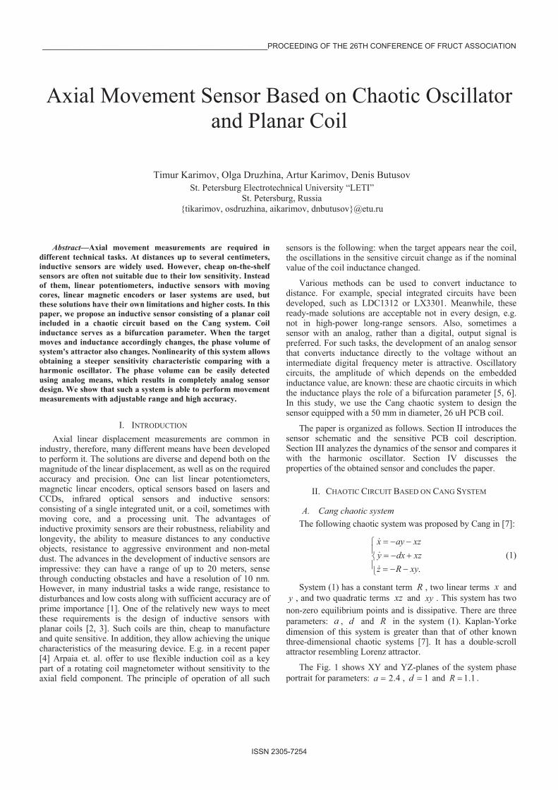
non-zero equilibrium points and is dissipative. There are three parameters: a , d and R in the system (1). Kaplan-Yorke dimension of this system is greater than that of other known three-dimensional chaotic systems [7]. It has a double-scroll attractor resembling Lorenz attractor.
The Fig. 1 shows XY and YZ-planes of the system phase portrait for parameters: 4.2a , 1d and 1.1R .
______________________________________________________PROCEEDING OF THE 26TH CONFERENCE OF FRUCT ASSOCIATION
ISSN 2305-7254
a) b)
Fig. 1. Phase portraits of the system (1)
a) b)
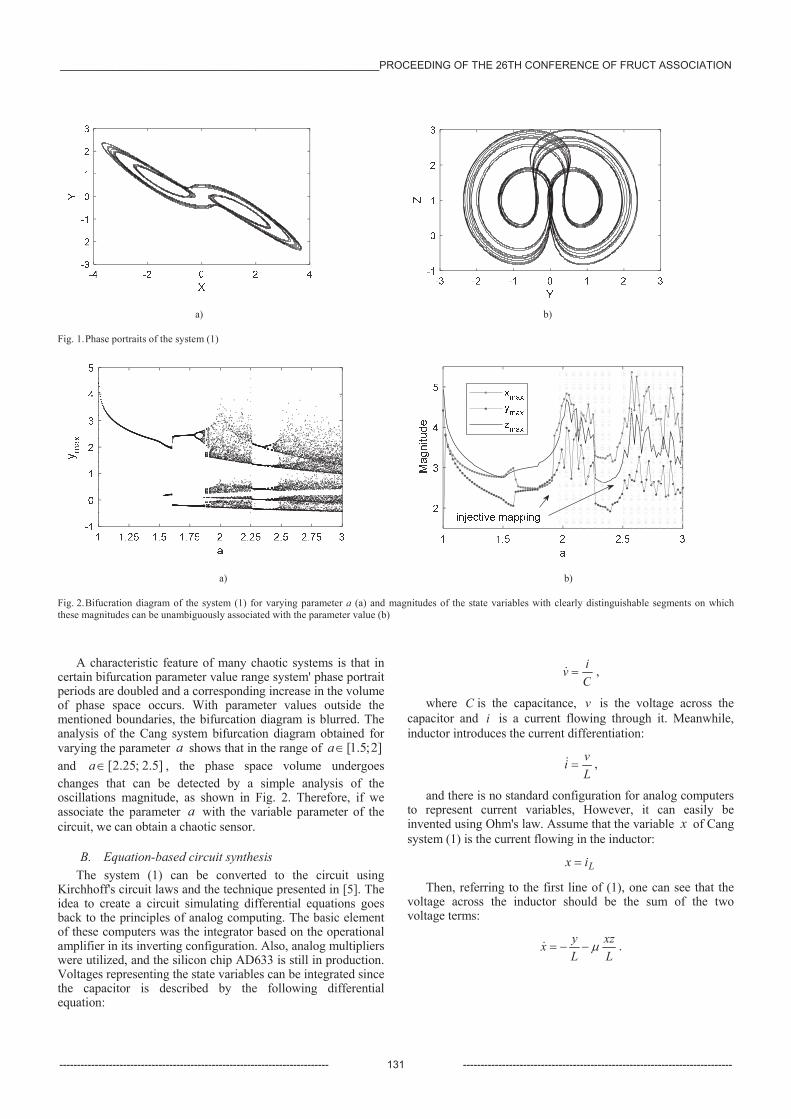
Fig. 2. Bifucration diagram of the system (1) for varying parameter a (a) and magnitudes of the state variables with clearly distinguishable segments on which these magnitudes can be unambiguously associated with the parameter value (b)
A characteristic feature of many chaotic systems is that in certain bifurcation parameter value range system' phase portrait periods are doubled and a corresponding increase in the volume of phase space occurs. With parameter values outside the mentioned boundaries, the bifurcation diagram is blurred. The analysis of the ang system bifurcation diagram obtained for varying the parameter a shows that in the range of ]2;5.1[a and ]5.2;25.2[a , the phase space volume undergoes changes that can be detected by a simple analysis of the oscillations magnitude, as shown in Fig. 2. Therefore, if we associate the parameter a with the variable parameter of the circuit, we can obtain a chaotic sensor.
B. Equation-based circuit synthesis The system (1) can be converted to the circuit using
Kirchhoff's circuit laws and the technique presented in [5]. The idea to create a circuit simulating differential equations goes back to the principles of analog computing. The basic element of these computers was the integrator based on the operational amplifier in its inverting configuration. Also, analog multipliers were utilized, and the silicon chip AD633 is still in production. Voltages representing the state variables can be integrated since the capacitor is described by the following differential equation:
Civ ,
where C is the capacitance, v is the voltage across the capacitor and i is a current flowing through it. Meanwhile, inductor introduces the current differentiation:
Lvi ,
and there is no standard configuration for analog computers to represent current variables, However, it can easily be invented using Ohm's law. Assume that the variable x of Cang system (1) is the current flowing in the inductor:
Lix
Then, referring to the first line of (1), one can see that the voltage across the inductor should be the sum of the two voltage terms:
Lxz
Lyx .
______________________________________________________PROCEEDING OF THE 26TH CONFERENCE OF FRUCT ASSOCIATION
---------------------------------------------------------------------------- 131 ----------------------------------------------------------------------------
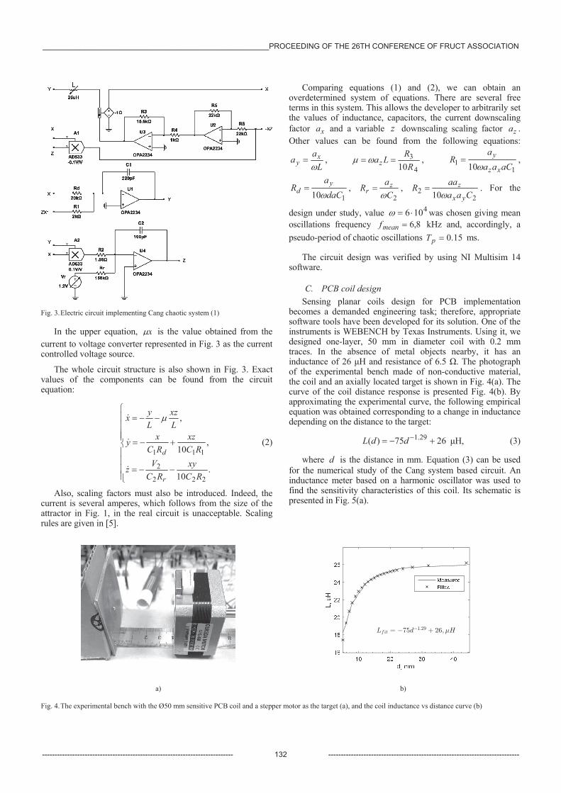
Fig. 3. Electric circuit implementing Cang chaotic system (1)
In the upper equation, x is the value obtained from the current to voltage converter represented in Fig. 3 as the current controlled voltage source.
The whole circuit structure is also shown in Fig. 3. Exact values of the components can be found from the circuit equation:
.10
,10
,
222
2
111
RCxy
RCVz
RCxz
RCxy
Lxz
Lyx
r
d (2)
Also, scaling factors must also be introduced. Indeed, the current is several amperes, which follows from the size of the attractor in Fig. 1, in the real circuit is unacceptable. Scaling rules are given in [5].
Comparing equations (1) and (2), we can obtain an overdetermined system of equations. There are several free terms in this system. This allows the developer to arbitrarily set the values of inductance, capacitors, the current downscaling factor xa and a variable z downscaling scaling factor za . Other values can be found from the following equations:
La
a xy ,
4
310R
RLaz , 1
1 10 aCaaa
Rxz
y ,
110 daCa
R yd ,
2CaR z
r , 2
2 10 CaaaaR
yx
z . For the
design under study, value 4106 was chosen giving mean oscillations frequency 8,6meanf kHz and, accordingly, a pseudo-period of chaotic oscillations 15.0pT ms.
The circuit design was verified by using NI Multisim 14 software.
C. PCB coil design Sensing planar coils design for PCB implementation
becomes a demanded engineering task; therefore, appropriate software tools have been developed for its solution. One of the instruments is WEBENCH by Texas Instruments. Using it, we designed one-layer, 50 mm in diameter coil with 0.2 mm traces. In the absence of metal objects nearby, it has an inductance of 26 H and resistance of 6.5 . The photograph of the experimental bench made of non-conductive material, the coil and an axially located target is shown in Fig. 4(a). The curve of the coil distance response is presented Fig. 4(b). By approximating the experimental curve, the following empirical equation was obtained corresponding to a change in inductance depending on the distance to the target:
2675)( 29.1ddL H, (3)
where d is the distance in mm. Equation (3) can be used for the numerical study of the Cang system based circuit. An inductance meter based on a harmonic oscillator was used to find the sensitivity characteristics of this coil. Its schematic is presented in Fig. 5(a).
a) b)
Fig. 4. The experimental bench with the Ø50 mm sensitive PCB coil and a stepper motor as the target (a), and the coil inductance vs distance curve (b)
______________________________________________________PROCEEDING OF THE 26TH CONFERENCE OF FRUCT ASSOCIATION
---------------------------------------------------------------------------- 132 ----------------------------------------------------------------------------
a) b)
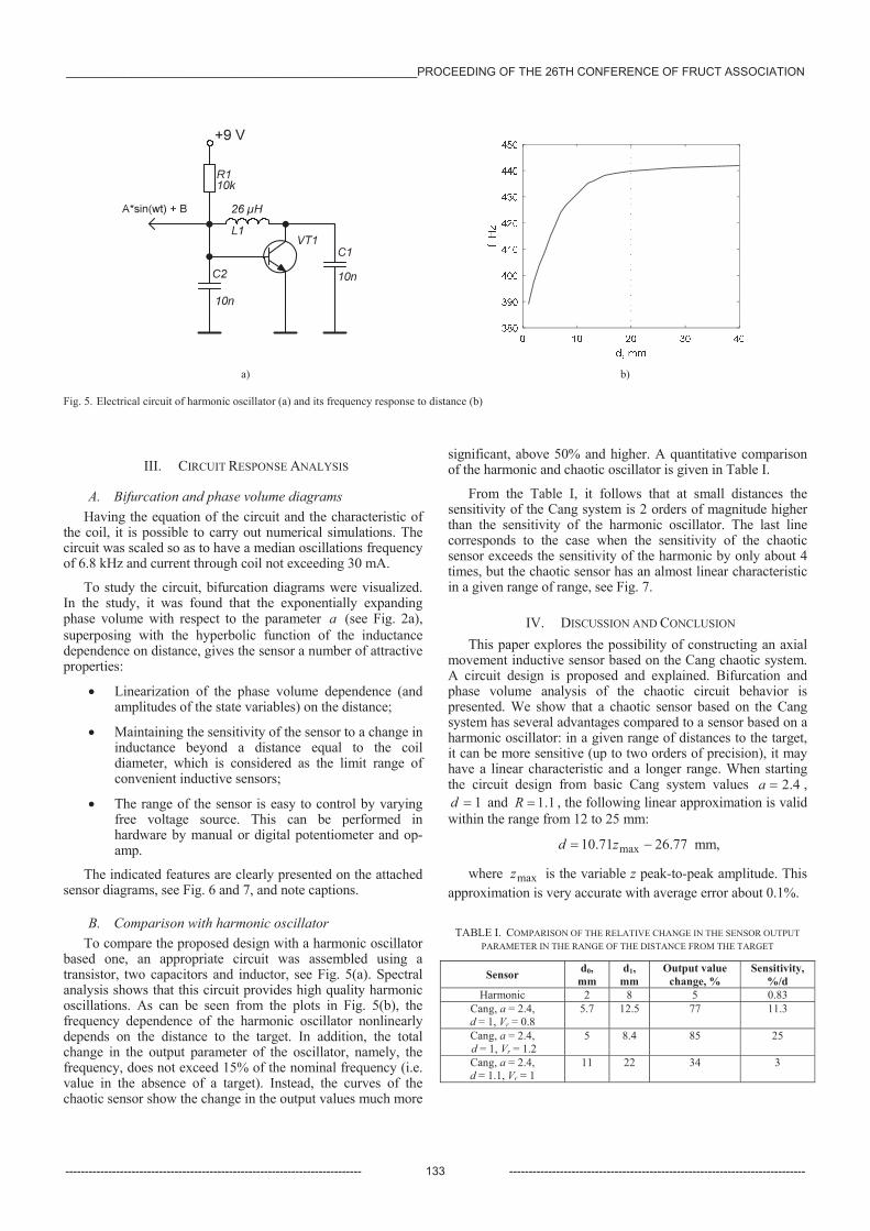
Fig. 5. Electrical circuit of harmonic oscillator (a) and its frequency response to distance (b)
III. CIRCUIT RESPONSE ANALYSIS
A. Bifurcation and phase volume diagrams Having the equation of the circuit and the characteristic of
the coil, it is possible to carry out numerical simulations. The circuit was scaled so as to have a median oscillations frequency of 6.8 kHz and current through coil not exceeding 30 mA.
To study the circuit, bifurcation diagrams were visualized. In the study, it was found that the exponentially expanding phase volume with respect to the parameter a (see Fig. 2a), superposing with the hyperbolic function of the inductance dependence on distance, gives the sensor a number of attractive properties:
Linearization of the phase volume dependence (and amplitudes of the state variables) on the distance;
Maintaining the sensitivity of the sensor to a change in inductance beyond a distance equal to the coil diameter, which is considered as the limit range of convenient inductive sensors;
The range of the sensor is easy to control by varying free voltage source. This can be performed in hardware by manual or digital potentiometer and op-amp.
The indicated features are clearly presented on the attached sensor diagrams, see Fig. 6 and 7, and note captions.
B. Comparison with harmonic oscillator To compare the proposed design with a harmonic oscillator
based one, an appropriate circuit was assembled using a transistor, two capacitors and inductor, see Fig. 5(a). Spectral analysis shows that this circuit provides high quality harmonic oscillations. As can be seen from the plots in Fig. 5(b), the frequency dependence of the harmonic oscillator nonlinearly depends on the distance to the target. In addition, the total change in the output parameter of the oscillator, namely, the frequency, does not exceed 15% of the nominal frequency (i.e. value in the absence of a target). Instead, the curves of the chaotic sensor show the change in the output values much more
significant, above 50% and higher. A quantitative comparison of the harmonic and chaotic oscillator is given in Table I.
From the Table I, it follows that at small distances the sensitivity of the Cang system is 2 orders of magnitude higher than the sensitivity of the harmonic oscillator. The last line corresponds to the case when the sensitivity of the chaotic sensor exceeds the sensitivity of the harmonic by only about 4 times, but the chaotic sensor has an almost linear characteristic in a given range of range, see Fig. 7.
IV. DISCUSSION AND CONCLUSION This paper explores the possibility of constructing an axial
movement inductive sensor based on the Cang chaotic system. A circuit design is proposed and explained. Bifurcation and phase volume analysis of the chaotic circuit behavior is presented. We show that a chaotic sensor based on the Cang system has several advantages compared to a sensor based on a harmonic oscillator: in a given range of distances to the target, it can be more sensitive (up to two orders of precision), it may have a linear characteristic and a longer range. When starting the circuit design from basic Cang system values 4.2a ,
1d and 1.1R , the following linear approximation is valid within the range from 12 to 25 mm:
.776210.71 maxzd mm,
where maxz is the variable z peak-to-peak amplitude. This approximation is very accurate with average error about 0.1%.
TABLE I. COMPARISON OF THE RELATIVE CHANGE IN THE SENSOR OUTPUT PARAMETER IN THE RANGE OF THE DISTANCE FROM THE TARGET
Sensor d0, mm
d1, mm
Output value change, %
Sensitivity, %/d
Harmonic 2 8 5 0.83 Cang, a = 2.4, d = 1, Vr = 0.8
5.7 12.5 77 11.3
Cang, a = 2.4, d = 1, Vr = 1.2
5 8.4 85 25
Cang, a = 2.4, d = 1.1, Vr = 1
11 22 34 3
______________________________________________________PROCEEDING OF THE 26TH CONFERENCE OF FRUCT ASSOCIATION
---------------------------------------------------------------------------- 133 ----------------------------------------------------------------------------
z max
, V
a) b)
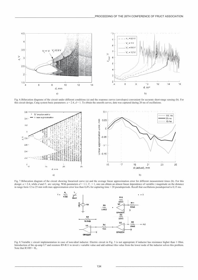
Fig. 6. Bifurcation diagrams of the circuit under different conditions (a) and the response curves (envelopes) convenient for accurate short-range sensing (b). For this circuit design, Cang system basic parameters: a = 2.4, d = 1. To obtain the smooth curves, data was captured during 20 ms of oscillations.
a) b)
Fig. 7. Bifurcation diagram of the circuit showing linearized curve (a) and the average linear approximation error for different measurement times (b). For this design: a = 2.4, while d and Vr are varying. With parameters d = 1.1, Vr = 1, one can obtain an almost linear dependence of variable z magnitude on the distance in range form 12 to 25 mm with max approximation error less than 0,4% for capturing time > 20 pseudoperiods. Recall that oscillations pseudoperiod is 0,15 ms.
Fig. 8. Variable x circuit implementation in case of non-ideal inductor. Electric circuit in Fig. 3 is not appropriate if inductor has resistance higher than 1 Ohm. Introduction of the op-amp U7 and resistors R9-R11 to invert x variable value and add subtract this value from the lower node of the inductor solves this problem. Note that R3/R9 = RL.
______________________________________________________PROCEEDING OF THE 26TH CONFERENCE OF FRUCT ASSOCIATION
---------------------------------------------------------------------------- 134 ----------------------------------------------------------------------------
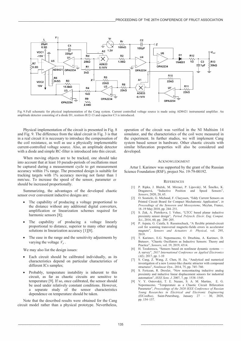
Fig. 9. Full schematic for physical implementation of the Cang system. Current controlled voltage source is made using AD8421 instrumental amplifier. An amplitude detector consisting of a diode D1, resitiors R12-13 and capacitor C3 is introduced.
Physical implementation of the circuit is presented in Fig. 8 and Fig. 9. The difference from the ideal circuit in Fig. 3 is that in a real circuit it is necessary to introduce the compensation of the coil resistance, as well as use a physically implementable current-controlled voltage source. Also, an amplitude detector with a diode and simple RC-filter is introduced into this circuit.
When moving objects are to be tracked, one should take into account that at least 10 pseudo-periods of oscillations must be captured during a measurement cycle to get measurement accuracy within 1% range. The presented design is suitable for tracking targets with 1% accuracy moving not faster than 1 mm/sec. To increase the speed of the sensor, parameter should be increased proportionally.
Summarizing, the advantages of the developed chaotic sensor over convenient inductive designs are:
The capability of producing a voltage proportional to the distance without any additional digital converters, amplification or linearization schemes required for harmonic sensors [8];
The capability of producing a voltage linearly proportional to distance, superior to many other analog solutions in linearization accuracy [1][8].
The ease in the range and the sensitivity adjustments by varying the voltage rV .
We may also list the design issues:
Each circuit should be calibrated individually, as its characteristics depend on particular characteristics of different ICs samples;
Probably, temperature instability is inherent to this circuit, as far as chaotic circuits are sensitive to temperature [9]. If so, once calibrated, the sensor should be used under relatively constant conditions. However, a separate study of the sensor characteristics dependence on temperature should be taken.
Note that the described results were obtained for the Cang circuit model rather than a physical prototype. Nevertheless,
operation of the circuit was verified in the NI Multisim 14 simulator, and the characteristics of the coil were measured in the experiment. In further studies, we will implement Cang system based sensor in hardware. Other chaotic circuits with similar bifurcation properties will also be considered and developed.
ACKNOWLEDGMENT Artur I. Karimov was supported by the grant of the Russian
Science Foundation (RSF), project No. 19-79-00192.
REFERENCES [1] P. Ripka, J. Blažek, M. Mirzaei, P. Lipovský, M. Šmelko, K.
Draganová, “Inductive Position and Speed Sensors”, Sensors, 2020, 20, 65.
[2] O. Sosnicki, G. Michaud, F. Claeyssen, “Eddy Current Sensors on Printed Circuit Board for Compact Mechatronic Application”, in Proceedings of the Sensoren und Messsysteme, Meylan, France, 18–19 May 2010, pp. 244–251.
[3] S. Zuk, A. Pietrikova, I. Vehec, “LTCC based planar inductive proximity sensor design”, Period. Polytech. Electr. Eng. Comput. Sci., 2016, 60, pp. 200–205.
[4] P. Arpaia, G. Caiafa, S. Russenschuck, “A flexible printed-circuit coil for scanning transversal magnetic-fields errors in accelerator magnets”, Sensors and Actuators A: Physical, vol. 295, 2019.
[5] T. Karimov, E.G. Nepomuceno, O. Druzhina, A. Karimov, D. Butusov. “Chaotic Oscillators as Inductive Sensors: Theory and Practice”, Sensors, vol. 19, 2019, 4314.
[6] H. Teodorescu, “Sensors based on nonlinear dynamic systems — A survey”, 2017 International Conference on Applied Electronics (AE), 2017, pp. 1-10
[7] S. Cang, Z. Wang, Z. Chen, H. Jia, “Analytical and numerical investigation of a new Lorenz-like chaotic attractor with compound structures”, Nonlinear Dyn., 2014, 75, pp. 745–760.
[8] S. Fericean, R. Droxler, “New noncontacting inductive analog proximity and inductive linear displacement sensors for industrial automation”, IEEE Sens. J. 2007, 7, pp. 1538–1545.
[9] V. Y. Ostrovskii, T. E. Nazare, S. A. M. Martins, E. G. Nepomuceno, “Temperature as a Chaotic Circuit Bifurcation Parameter”, Proceedings of the 2020 IEEE Conference of Russian Young Researches in Electrical and Electronic Engineering (ElConRus), Saint-Petersburg, January 27 – 30, 2020, pp. 154–157.
______________________________________________________PROCEEDING OF THE 26TH CONFERENCE OF FRUCT ASSOCIATION
---------------------------------------------------------------------------- 135 ----------------------------------------------------------------------------