Embed Size (px)
Citation preview
Advanced Technologies in Earth Sciences
Axel LiebscherUte Münch Editors
Geological Storage of CO2 – Long Term Security AspectsGEOTECHNOLOGIEN Science Report No. 22

Advanced Technologies in Earth Sciences
Series editors
Ute Münch, Potsdam, GermanyLudwig Stroink, Potsdam, GermanyVolker Mosbrugger, Frankfurt, GermanyGerold Wefer, Bremen, Germany

More information about this series at: http://www.springer.com/series/8384
Axel Liebscher • Ute MünchEditors
Geological Storageof CO2 – Long TermSecurity AspectsGEOTECHNOLOGIENScience Report No. 22
123
EditorsAxel LiebscherTelegrafenbergGFZ German Research Centrefor Geosciences
Centre for Geological Storage CGSPotsdamGermany
Ute MünchCoordination OfficeGEOTECHNOLOGIENPotsdamGermany
ISSN 2190-1635 ISSN 2190-1643 (electronic)Advanced Technologies in Earth SciencesISBN 978-3-319-13929-6 ISBN 978-3-319-13930-2 (eBook)DOI 10.1007/978-3-319-13930-2
Library of Congress Control Number: 2014960205
Springer Cham Heidelberg New York Dordrecht London© Springer International Publishing Switzerland 2015This work is subject to copyright. All rights are reserved by the Publisher, whether the whole or partof the material is concerned, specifically the rights of translation, reprinting, reuse of illustrations,recitation, broadcasting, reproduction on microfilms or in any other physical way, and transmissionor information storage and retrieval, electronic adaptation, computer software, or by similar ordissimilar methodology now known or hereafter developed.The use of general descriptive names, registered names, trademarks, service marks, etc. in thispublication does not imply, even in the absence of a specific statement, that such names are exemptfrom the relevant protective laws and regulations and therefore free for general use.The publisher, the authors and the editors are safe to assume that the advice and information in thisbook are believed to be true and accurate at the date of publication. Neither the publisher nor theauthors or the editors give a warranty, express or implied, with respect to the material containedherein or for any errors or omissions that may have been made.
Printed on acid-free paper
Springer International Publishing AG Switzerland is part of Springer Science+Business Media(www.springer.com)
Foreword
“Advanced Technologies in Earth Sciences” is based on the German GeoscientificResearch and Development Programme “GEOTECHNOLOGIEN” funded by theFederal Ministry of Education and Research (BMBF) and the German ResearchFoundation (DFG).
This programme comprises a nationwide network of transdisciplinary researchprojects and incorporates numerous universities, non-university research institu-tions and companies. The books in this series deal with research results fromdifferent innovative geoscientific research areas, interlinking a broad spectrum ofdisciplines with a view to documenting System Earth as a whole, including itsvarious sub-systems and cycles. The research topics are predefined to meet scien-tific, socio-political and economic demands for the future.
Ute MünchLudwig Stroink
Volker MosbruggerGerold Wefer
v
Preface
Over the next decades global energy consumption will continue to increase. Despiteadvances in the transition to renewable energy sources, fossil fuels will neverthelesscontinue to dominate global primary energy consumption and their combustion willfurther fuel atmospheric carbon dioxide (CO2) concentrations and global warming.While energy efficiency and increasing share of non-fossil energy generation willcontribute to the de-carbonization of the energy system, Carbon Capture andStorage (CCS) is the only available technology that allows reducing CO2 emissionsarising from usage of fossil fuels. CCS may be applied to fossil-fuel-based powergeneration, industrial processes (steel, cement, refineries) and power generationfrom biomass; in the latter case, CCS may also result in net negative CO2 emis-sions. Central to CCS is the secure and long-term storage of the captured CO2 indeep geological formations preventing the CO2 from escaping into the atmosphere.Although geological CO2 storage builds on experiences from hydrocarbon industryand underground storage of natural and town gas, it poses specific challenges on,amongst others, geochemical and geophysical reservoir understanding, reservoirengineering and storage operation, monitoring techniques, material properties,long-term security and risk assessment and management, as well as communicationstrategies with the different stakeholders. These challenges have to be addressedand solved to ensure industrial implementation readiness of CCS in the near future.
To address these challenges, the German Federal Ministry of Education andResearch (BMBF) has initiated and funded several scientific projects for thedevelopment of the necessary scientific and technological knowledge base forgeological CO2 storage in the framework of its Research and Development Pro-gramme GEOTECHNOLOGIEN. Since 2005, a total of 33 research projects on thedifferent aspects of geological CO2 storage have been and are still funded withinthree successive funding periods. Due to this effort, Germany has gained substantialscientific and technological know-how in the field of geological CO2 storage. Froma scientific and technological perspective, the results and outcomes of the differentprojects lay the fundamentals for secure and reliable implementation of demo-scaleprojects on CO2 storage.
vii
In eleven individual chapters, this volume compiles and reviews the main resultsfrom the most recent research and development projects on geological storage ofCO2 funded by the third funding period under the GEOTECHNOLOGIEN Pro-gramme. The projects concentrate on the development of innovative technologiesand processes for the reliable assessment of the operational/long-term safety ofpotential and existing CO2 storages. The main goals were the developmentof methods for the identification and comprehension of security relevant processesof possible weak points (e.g. faults) of the cap rock—from the reservoir to thesurface as well as the prognosis of the influence of industrially sequestered CO2 onreservoir rock and cap rock. Furthermore, experimental analysis of thermodynamicand kinetic data were carried out to model complex reactions between injected CO2,associate material, natural formation water and mineral phases. In addition, furtherdevelopments on reactive multiphase transport models were realized. In this con-text, the analysis of coupled hydraulic and geo-mechanical processes in the reser-voir and cap rock with regard to the deformation and mechanical reactions of thecap rock and alterations at the surface are explained in the volume. Furthermore,hydrodynamical reservoir modelling with regard to the replacement of formationfluids to avoid contaminations (e.g. of the groundwater) were developed to ensurethe long-term security of a CO2 storage site. Therefore, the development andrealization of effective and efficient technologies to monitor the lateral CO2 andpressure extension and footprint and the replacement of brines were investigated.
Geophysical methods, numerical modelling procedures, microbiological inves-tigations as well as the development of new optical sensor technologies and theircombination will be explained in detail in this volume. Laboratory as well as fieldstudies in Germany, e.g. at the Ketzin pilot site, but also with international partnersin Canada and Australia were carried out to merge the already existing expertise inthe field of Carbon Capture and Storage (CCS).
In addition to the technical natural science-dominated methods and techniques,social scientists were involved in several projects to evaluate the opportunities andlimits for the acceptance of CCS in Germany. On the basis of data from completedprojects, using new research approaches to close the existing gaps in acceptanceresearch were investigated. Furthermore, analyses of factors influencing acceptanceas well as an assessment of participatory methods were analysed.
Axel LiebscherHead of Centre for Geological Storage CGS,
GFZ German Research Centre for Geosciences
Ute MünchHead of the GEOTECHNOLOGIEN coordination office
viii Preface
Contents
Joint Research Project CO2MAN (CO2MAN ReservoirManagement): Continuation of Research and DevelopmentWork for CO2 Storage at the Ketzin Pilot Site . . . . . . . . . . . . . . . . . . 1Sonja Martens, Ronald Conze, Marco De Lucia, Jan Henninges,Thomas Kempka, Axel Liebscher, Stefan Lüth, Fabian Möller,Ben Norden, Bernhard Prevedel, Cornelia Schmidt-Hattenberger,Alexandra Szizybalski, Andrea Vieth-Hillebrand, Hilke Würdemann,Kornelia Zemke and Martin Zimmer
MONACO—Monitoring Approach for Geological CO2 StorageSites Using a Hierarchical Observation Concept . . . . . . . . . . . . . . . . . 33Claudia Schütze, Karin Bräuer, Peter Dietrich, Viktoria Engnath,Michael Gisi, Gunnar Horak, Carsten Leven, Alexander Lübben, Ingo Möller,Michael Nierychlo, Stefan Schlömer, Andreas Schuck, Ulrich Serfling,Arno Simon, Thomas Streil and Uta Sauer
Advances in Stable Isotope Monitoring of CO2 Under ElevatedPressures, Temperatures and Salinities: Selected Resultsfrom the Project CO2ISO-LABEL . . . . . . . . . . . . . . . . . . . . . . . . . . . 59Johannes A.C. Barth, Michael Mader, Anssi Myrttinen, Veith Becker,Robert van Geldern and Bernhard Mayer
CO2BioPerm—Influence of Bio-geochemical CO2-TransformationProcesses on the Long-Term Permeability. . . . . . . . . . . . . . . . . . . . . . 73Nils Hoth, Claudia Gniese, Jana Rakoczy, Anne Weber,Steffen Kümmel, Susan Reichel, Carsten Freese, Michaela Hache,Andrea Kassahun, Alexandra Schulz, Heike Fischer, Martin Mühling,Robert Starke, Rene Kahnt, Carsten Vogt, Hans-Hermann Richnow,Martin Krüger, Axel Schippers and Michael Schlömann
ix
Seismic and Sub-seismic Deformation Prediction in the Contextof Geological Carbon Trapping and Storage . . . . . . . . . . . . . . . . . . . . 97Charlotte M. Krawczyk, David C. Tanner, Andreas Henk,Henning Trappe, Jennifer Ziesch, Thies Beilecke, Chiara M. Aruffo,Bastian Weber, Andrea Lippmann, Uwe-Jens Görke, Lars Bilkeand Olaf Kolditz
Long-Term Safety of Well Abandonment: First Resultsfrom Large Scale Laboratory Experiments (COBRA) . . . . . . . . . . . . . 115Frank R. Schilling, Andreas Bieberstein, Jörg-Detlef Eckhardt,Michael Haist, Astrid Hirsch, Steffen Klumbach, Marco Kromer,Josephin Mühlbach, Birgit I.R. Müller, Harald S. Müller, Thomas Neumann,Stefan Schläger and Theodoros Triantafyllidis
“CO2RINA”—CO2 Storage Risk Integrated Analysis . . . . . . . . . . . . . 139René Kahnt, Alexander Kutzke, Mirko Martin, Michael Eckart,Ralph Schlüter, Thomas Kempka, Elena Tillner, Alexandra Hildenbrand,Bernhard M. Krooss, Yves Gensterblum, Markus Adams,Martin Feinendegen, Stefan Klebingat and Christoph Neukum
Saltwater Monitoring Using Long-Electrode ERT . . . . . . . . . . . . . . . . 167Thomas Günther, Mathias Ronczka and Thomas Voß
Joint Research Project Brine: Carbon Dioxide Storagein Eastern Brandenburg: Implications for Synergetic GeothermalHeat Recovery and Conceptualization of an Early WarningSystem Against Freshwater Salinization . . . . . . . . . . . . . . . . . . . . . . . 183Thomas Kempka, Rainer Herd, Ernst Huenges, Ricarda Endler,Christoph Jahnke, Silvio Janetz, Egbert Jolie, Michael Kühn,Fabien Magri, Peter Meinert, Inga Moeck, Marcus Möller,Gerard Munoz, Oliver Ritter, Wladislaw Schafrik,Cornelia Schmidt-Hattenberger, Elena Tillner, Hans-Jürgen Voigtand Günter Zimmermann
Combined Natural and Social Science Approachfor Regional-Scale Characterisation of CO2 StorageFormations and Brine Migration Risks (CO2BRIM) . . . . . . . . . . . . . . 209Holger Class, Alexander Kissinger, Stefan Knopf, Wilfried Konrad,Vera Noack and Dirk Scheer
Chances for and Limitations of Acceptance for CCS in Germany . . . . 229Elisabeth Dütschke, Diana Schumann and Katja Pietzner
x Contents
Joint Research Project CO2MAN(CO2MAN Reservoir Management):Continuation of Researchand Development Work for CO2 Storageat the Ketzin Pilot Site
Sonja Martens, Ronald Conze, Marco De Lucia, Jan Henninges,Thomas Kempka, Axel Liebscher, Stefan Lüth, Fabian Möller,Ben Norden, Bernhard Prevedel, Cornelia Schmidt-Hattenberger,Alexandra Szizybalski, Andrea Vieth-Hillebrand, Hilke Würdemann,Kornelia Zemke and Martin Zimmer
Abstract The joint project CO2MAN (CO2 Reservoir Management) was a scien-tific programme accompanying geological CO2 storage at the Ketzin pilot site in theGerman Federal State of Brandenburg. The project which was funded by theGerman Federal Ministry of Education and Research (BMBF) from 1 September2010 to 31 December 2013 enclosed six scientific institutions and seven industrypartners. The Ketzin pilot site is the longest-operating on-shore CO2 storage site inEurope. In advance of the CO2MAN project, CO2 injection had already started inJune 2008 and storage operation had been accompanied by one of the world’s mostextensive scientific research and development programmes. The CO2MAN projecttook advantage of this unique potential of the site in order to answer furthertechnical and scientific questions on CO2 storage and to inform about this highlydebated technology. The CO2MAN project demonstrates safe geological CO2
storage at the Ketzin site on a pilot scale.
1 Introduction
CO2MAN which stands for CO2 Reservoir Management was a scientific pro-gramme accompanying geological CO2 storage at the Ketzin pilot site. Within theframework of CO2MAN a total of six German scientific institutions and seven
S. Martens (&) � R. Conze �M. De Lucia � J. Henninges � T. Kempka � A. Liebscher � S. LüthF. Möller � B. Norden � B. Prevedel � C. Schmidt-Hattenberger � A. SzizybalskiA. Vieth-Hillebrand � H. Würdemann � K. Zemke � M. ZimmerHelmholtz Centre Potsdam, GFZ German Research Centre for Geosciences,Telegrafenberg, 14473 Potsdam, Germanye-mail: [email protected]
© Springer International Publishing Switzerland 2015A. Liebscher and U. Münch (eds.), Geological Storage of CO2 – Long TermSecurity Aspects, Advanced Technologies in Earth Sciences,DOI 10.1007/978-3-319-13930-2_1
1
industry partners from Norway, Austria and Germany participated (Fig. 1). Thejoint project was coordinated by the GFZ German Research Centre for Geosciencesin close cooperation with all partners.
The Ketzin pilot site for geological storage of CO2 is located about 25 km westof Berlin in the German Federal State of Brandenburg (Fig. 2). It is the longestoperating European on-shore CO2 storage pilot site and provides an in situ labo-ratory for CO2 storage in a saline aquifer of the Northeast German Basin. Injectionof CO2 at Ketzin started on 30 June 2008 and was accompanied by one of the mostcomprehensive scientific research and development (R&D) programmes worldwidewith key objectives being R&D on injection operation, monitoring and modelling.The first results that had been achieved at the pilot site Ketzin were promising(Schilling et al. 2009a; Würdemann et al. 2010). However, for a final assessment ofthe technology further investigations were necessary (Stroink et al. 2009). Hencethe aim of the CO2MAN project was to take advantage of the unique potential andthe infrastructure of the Ketzin pilot site and to continue CO2 injection and theR&D activities with a dedicated public outreach programme. The key objectives ofthe joint research project were:
• to monitor the migration of the injected CO2, to determine the sensitivity ofindividual monitoring methods and to test and develop geophysical monitoringconcepts for CO2 storage sites,
• to characterize and quantify CO2-induced interactions between fluid, rock andmicrobial community in the storage system,
• to validate tools for static modelling and dynamic simulations for the Ketzinpilot site, and
• to inform the public, stakeholders, decision makers and regulatory authoritiesabout CO2 storage.
Fig. 1 CO2MAN partners from academia and industry. The consortium includes GFZ GermanCentre Research for Geosciences (coordinator) in Potsdam, Friedrich-Alexander University ofErlangen-Nürnberg, University of Stuttgart (Department of Hydromechanics and Modelling ofHydrosystems (LH2)), University of Leipzig and the Helmholtz Centre for EnvironmentalResearch -UFZ in Leipzig. Industry partners are Dillinger Hüttenwerke, OMV, RWE, Saarstahl,Statoil, Vattenfall and VGS
2 S. Martens et al.
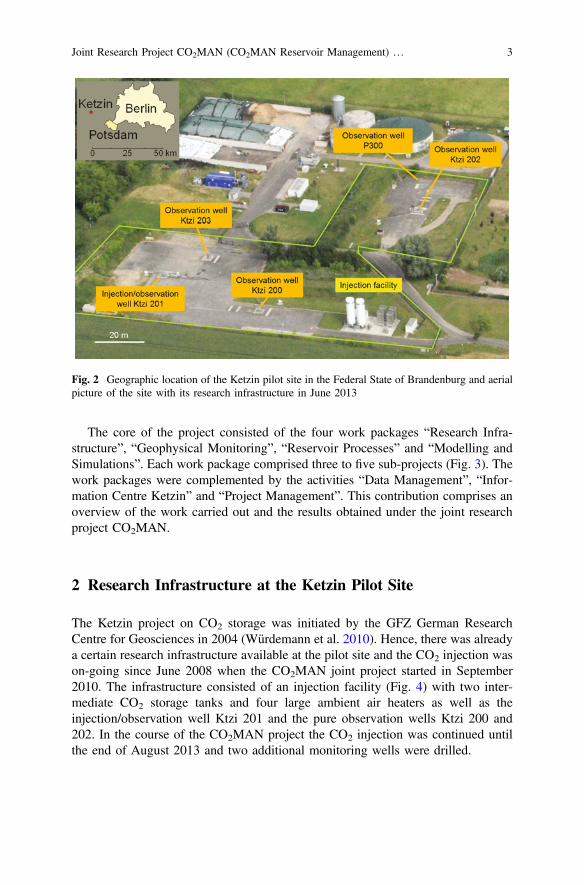
The core of the project consisted of the four work packages “Research Infra-structure”, “Geophysical Monitoring”, “Reservoir Processes” and “Modelling andSimulations”. Each work package comprised three to five sub-projects (Fig. 3). Thework packages were complemented by the activities “Data Management”, “Infor-mation Centre Ketzin” and “Project Management”. This contribution comprises anoverview of the work carried out and the results obtained under the joint researchproject CO2MAN.
2 Research Infrastructure at the Ketzin Pilot Site
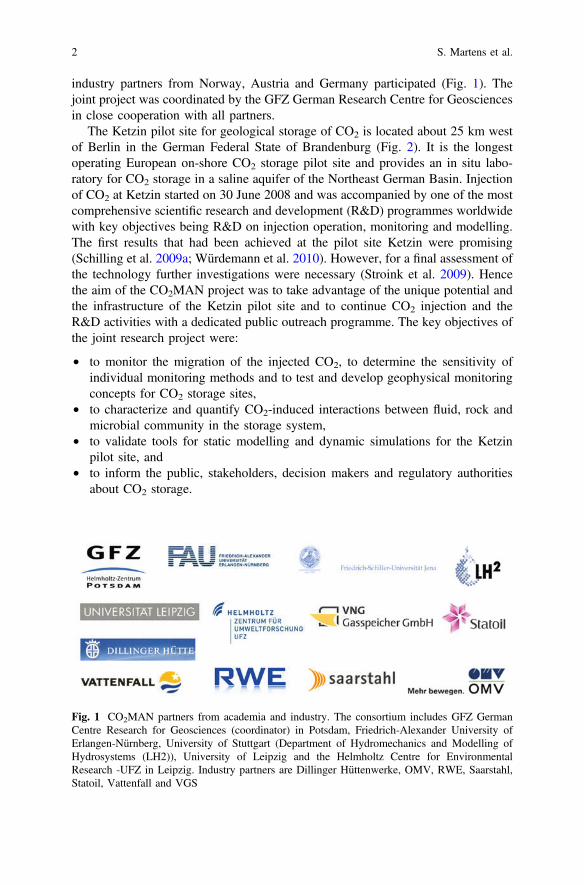
The Ketzin project on CO2 storage was initiated by the GFZ German ResearchCentre for Geosciences in 2004 (Würdemann et al. 2010). Hence, there was alreadya certain research infrastructure available at the pilot site and the CO2 injection wason-going since June 2008 when the CO2MAN joint project started in September2010. The infrastructure consisted of an injection facility (Fig. 4) with two inter-mediate CO2 storage tanks and four large ambient air heaters as well as theinjection/observation well Ktzi 201 and the pure observation wells Ktzi 200 and202. In the course of the CO2MAN project the CO2 injection was continued untilthe end of August 2013 and two additional monitoring wells were drilled.
Fig. 2 Geographic location of the Ketzin pilot site in the Federal State of Brandenburg and aerialpicture of the site with its research infrastructure in June 2013
Joint Research Project CO2MAN (CO2MAN Reservoir Management) … 3
2.1 Storage Operation
Injection of CO2 at the Ketzin pilot site started already prior to the CO2MANproject on 30 June 2008 and ended on 29 August 2013. The CO2 was delivered byroad tankers in a liquid state and stored at about −18 °C and 21 bars in the twointermediate storage tanks on site (Fig. 4). Prior to injection the pressure was raisedby plunger pumps to the necessary injection pressure and the CO2 was heated byambient air heaters and an electrical heater. Then the CO2 was transported via apipeline of about 100 m length to the injection well Ktzi 201. A total amount of67 kt of CO2 was safely injected over the more than 5 years period. Thereof,29,337 t were injected within the CO2MAN project (Fig. 5). During most of thetime food-grade CO2 (purity > 99.9 vol%) was used with monthly injection ratesbetween 1,000 and 2,300 t. From May to June 2011, 1,515 t of CO2 captured fromthe Vattenfall Schwarze Pumpe oxyfuel pilot plant (purity > 99.7 vol%) were used.
CO2 injection was accompanied by a comprehensive operational pressure-tem-perature monitoring programme (Liebscher et al. 2013). Due to CO2 injection thereservoir pressure increased to about 76–79 bars already after eighth months ofinjection (Fig. 5). After this initial increase the reservoir pressure slightly decreased
Fig. 3 Organization chart of the joint project CO2MAN, showing the different work packages,sub-projects and respective lead scientists
4 S. Martens et al.
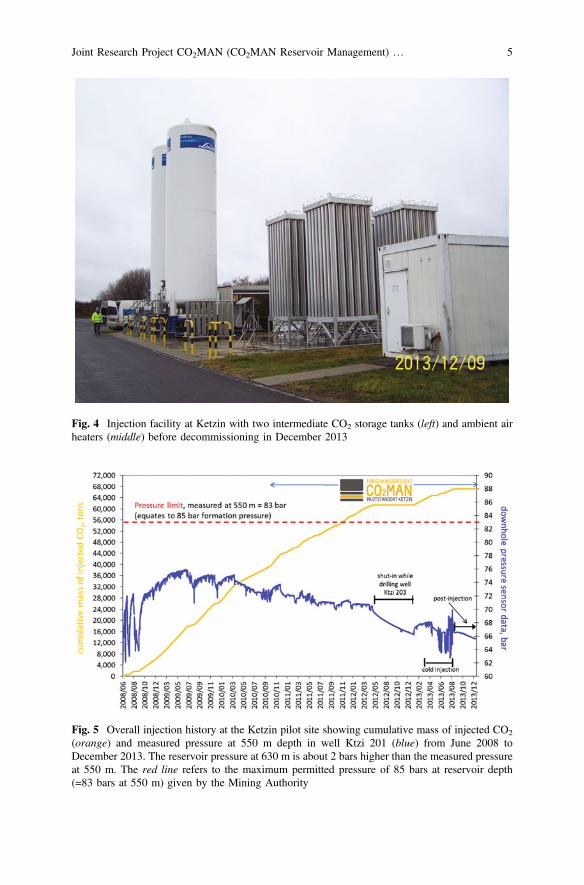
Fig. 4 Injection facility at Ketzin with two intermediate CO2 storage tanks (left) and ambient airheaters (middle) before decommissioning in December 2013
Fig. 5 Overall injection history at the Ketzin pilot site showing cumulative mass of injected CO2
(orange) and measured pressure at 550 m depth in well Ktzi 201 (blue) from June 2008 toDecember 2013. The reservoir pressure at 630 m is about 2 bars higher than the measured pressureat 550 m. The red line refers to the maximum permitted pressure of 85 bars at reservoir depth(=83 bars at 550 m) given by the Mining Authority
Joint Research Project CO2MAN (CO2MAN Reservoir Management) … 5
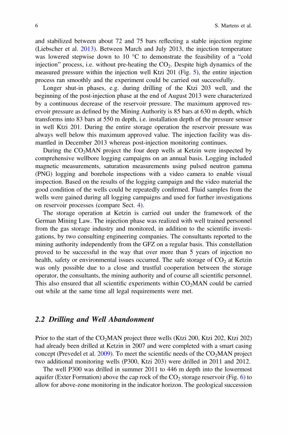
and stabilized between about 72 and 75 bars reflecting a stable injection regime(Liebscher et al. 2013). Between March and July 2013, the injection temperaturewas lowered stepwise down to 10 °C to demonstrate the feasibility of a “coldinjection” process, i.e. without pre-heating the CO2. Despite high dynamics of themeasured pressure within the injection well Ktzi 201 (Fig. 5), the entire injectionprocess ran smoothly and the experiment could be carried out successfully.
Longer shut-in phases, e.g. during drilling of the Ktzi 203 well, and thebeginning of the post-injection phase at the end of August 2013 were characterizedby a continuous decrease of the reservoir pressure. The maximum approved res-ervoir pressure as defined by the Mining Authority is 85 bars at 630 m depth, whichtransforms into 83 bars at 550 m depth, i.e. installation depth of the pressure sensorin well Ktzi 201. During the entire storage operation the reservoir pressure wasalways well below this maximum approved value. The injection facility was dis-mantled in December 2013 whereas post-injection monitoring continues.
During the CO2MAN project the four deep wells at Ketzin were inspected bycomprehensive wellbore logging campaigns on an annual basis. Logging includedmagnetic measurements, saturation measurements using pulsed neutron gamma(PNG) logging and borehole inspections with a video camera to enable visualinspection. Based on the results of the logging campaign and the video material thegood condition of the wells could be repeatedly confirmed. Fluid samples from thewells were gained during all logging campaigns and used for further investigationson reservoir processes (compare Sect. 4).
The storage operation at Ketzin is carried out under the framework of theGerman Mining Law. The injection phase was realized with well trained personnelfrom the gas storage industry and monitored, in addition to the scientific investi-gations, by two consulting engineering companies. The consultants reported to themining authority independently from the GFZ on a regular basis. This constellationproved to be successful in the way that over more than 5 years of injection nohealth, safety or environmental issues occurred. The safe storage of CO2 at Ketzinwas only possible due to a close and trustful cooperation between the storageoperator, the consultants, the mining authority and of course all scientific personnel.This also ensured that all scientific experiments within CO2MAN could be carriedout while at the same time all legal requirements were met.
2.2 Drilling and Well Abandonment
Prior to the start of the CO2MAN project three wells (Ktzi 200, Ktzi 202, Ktzi 202)had already been drilled at Ketzin in 2007 and were completed with a smart casingconcept (Prevedel et al. 2009). To meet the scientific needs of the CO2MAN projecttwo additional monitoring wells (P300, Ktzi 203) were drilled in 2011 and 2012.
The well P300 was drilled in summer 2011 to 446 m depth into the lowermostaquifer (Exter Formation) above the cap rock of the CO2 storage reservoir (Fig. 6) toallow for above-zone monitoring in the indicator horizon. The geological succession
6 S. Martens et al.
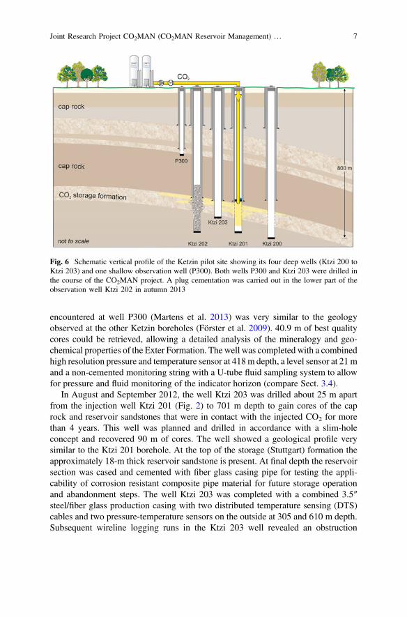
encountered at well P300 (Martens et al. 2013) was very similar to the geologyobserved at the other Ketzin boreholes (Förster et al. 2009). 40.9 m of best qualitycores could be retrieved, allowing a detailed analysis of the mineralogy and geo-chemical properties of the Exter Formation. The well was completed with a combinedhigh resolution pressure and temperature sensor at 418m depth, a level sensor at 21mand a non-cemented monitoring string with a U-tube fluid sampling system to allowfor pressure and fluid monitoring of the indicator horizon (compare Sect. 3.4).
In August and September 2012, the well Ktzi 203 was drilled about 25 m apartfrom the injection well Ktzi 201 (Fig. 2) to 701 m depth to gain cores of the caprock and reservoir sandstones that were in contact with the injected CO2 for morethan 4 years. This well was planned and drilled in accordance with a slim-holeconcept and recovered 90 m of cores. The well showed a geological profile verysimilar to the Ktzi 201 borehole. At the top of the storage (Stuttgart) formation theapproximately 18-m thick reservoir sandstone is present. At final depth the reservoirsection was cased and cemented with fiber glass casing pipe for testing the appli-cability of corrosion resistant composite pipe material for future storage operationand abandonment steps. The well Ktzi 203 was completed with a combined 3.5″steel/fiber glass production casing with two distributed temperature sensing (DTS)cables and two pressure-temperature sensors on the outside at 305 and 610 m depth.Subsequent wireline logging runs in the Ktzi 203 well revealed an obstruction
Fig. 6 Schematic vertical profile of the Ketzin pilot site showing its four deep wells (Ktzi 200 toKtzi 203) and one shallow observation well (P300). Both wells P300 and Ktzi 203 were drilled inthe course of the CO2MAN project. A plug cementation was carried out in the lower part of theobservation well Ktzi 202 in autumn 2013
Joint Research Project CO2MAN (CO2MAN Reservoir Management) … 7
inside the 3.5″ production casing at 557 m that required a work-over operation inorder to remove this section which was blocked by cement. This operation wasconducted in April/May 2013 and freed the inside of the casing so that logging toolsand a perforation gun could reach the CO2 injection horizons and finally connectthe well to the reservoir.
As the begin of a staged well abandonment at the Ketzin pilot site, a plugcementation in the form of a partial abandonment of well Ktzi 202 (Fig. 6) wascarried out in autumn 2013. As this well was a monitoring borehole since 2007 itwas entirely filled with CO2 under elevated pressure. In order to start the aban-donment the well had to be pressure killed by injecting NaCl brine from the surfaceinto the wellhead and such pushing the CO2 back into the storage formation. Bythat means a brine filled and secured borehole situation could be established and thewellhead could be safely removed and replaced by a blow-out preventer for thesubsequent plug cementing work in the reservoir section. A special CO2 resistantcement (EverCrete) was chosen which will be partly core-drilled and analyzed inthe course of the follow-up project COMPLETE in 2015.
3 Monitoring of the Ketzin Pilot Site
R&D on monitoring of the Ketzin pilot site was one of the key objectives of theCO2MAN project. Already in advance of this joint research project, a compre-hensive monitoring concept which combined operational, geophysical, geochemicaland microbiological monitoring techniques had been tested and established at thepilot site (Würdemann et al. 2010).
In the framework of CO2MAN, geophysical techniques including boreholemonitoring, active seismic and geoelectric methods were continued in order tofurther monitor the migration of the injected CO2 on different scales. Gas geo-chemical monitoring focused on CO2 soil flux measurements at the surface andfluid sampling from the wells via permanently installed capillary riser tubes and aU-tube system.
3.1 Borehole Monitoring
The migration of the injected CO2 close to the boreholes was monitored using acombination of different well logging techniques. The temperature distribution alongthe deep boreholes was continuously recorded with permanently installed distributedtemperature sensing (DTS) cables. The saturation conditions within the CO2 storagehorizon and the cap rock were investigated using pulsed neutron-gamma (PNG)logging. Furthermore, the heat-pulse method was tested for monitoring of saturationchanges. Here the formation thermal conductivity is determined based on temperaturechanges under the influence of a controlled heat source. For this purpose, a combined
8 S. Martens et al.
opto-electric sensor-heater cable was installed behind casing in the new observationwell Ktzi 203.
After filling up with CO2 the temperature conditions in the deep observationwells are controlled by a heat-pipe process (Henninges et al. 2011). Temperaturechanges are caused by phase transitions during evaporation and condensation ofCO2, and characteristic temperature gradients are established in the two-phase zone.The pressure evolution along the borehole depends on the composition and thephase distribution within the fluid column (Loizzo et al. 2013).
For the Ktzi 203 well, in situ thermal conductivities were calculated bynumerical inversion of the data acquired during heat-pulse measurements. Thethermal conductivity profiles show a good correlation with lithological changes,with values ranging between 1 and 4.5 Wm−1K−1. They display similar charac-teristics as the profiles previously determined for the other wells (Freifeld et al.2009). Within the storage horizon, changes of thermal conductivity in the order of20–30 % could be observed between different measurements, but the results show ahigh sensitivity against external thermal influences.
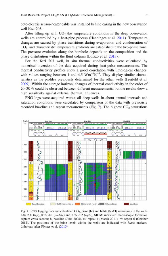
PNG logs were acquired within all deep wells in about annual intervals andsaturation conditions were calculated by comparison of the data with previouslyrecorded baseline and repeat measurements (Fig. 7). The highest CO2 saturations
Fig. 7 PNG logging data and calculated CO2, brine (br) and halite (NaCl) saturations in the wellsKtzi 200 (left), Ktzi 201 (middle) and Ktzi 202 (right). SIGM: measured macroscopic formationcapture cross-section; b: baseline (June 2008), r4: repeat 4 (March 2011), r6: repeat 6 (October2012). The positions of the brine levels within the wells are indicated with black markers.Lithology after Förster et al. (2010)
Joint Research Project CO2MAN (CO2MAN Reservoir Management) … 9
occur at the injection well Ktzi 201, with average values of 68 %, and up to 100 %locally. At the observation wells CO2 saturations are lower, with average values of> 60 % at well Ktzi 200, and a further decrease towards well Ktzi 202 (aver-ages < 60 %). A new PNG saturation model for CO2 and NaCl brine was developedwhich besides displacement also accounts for evaporation and precipitation pro-cesses (Baumann 2013; Baumann et al. 2014). Based on this model and the PNGmeasurements salt precipitation at the CO2-brine contact in the Ktzi 201 near-wellarea could be shown for the first time.
Within the cap rock, no indications for accumulation of CO2 in shalloweraquifers were observed. This is important evidence that no significant migration ofCO2 along the boreholes is occurring. The calculated saturations were used as inputparameters for estimates of the CO2 mass contained within the storage horizonbased on seismic data (Ivanova et al. 2012; see below) and for evaluation ofelectrical resistivity tomography data (Bergmann et al. 2012; see below). Theestablished fiber-optic sensor cable network also exhibits favorable properties forseismic surveys using the newly emerging method of distributed acoustic sensingDAS (Daley et al. 2013).
3.2 Seismics
The main task of seismic monitoring at the Ketzin pilot site is to image the lateraland vertical propagation of the injected CO2 in the reservoir. To this end, high-resolution vertical seismic profiling (VSP), star-profile surveys close to the injectionlocation (Ivandic et al. 2012) and large scale 3D surface seismic surveys (Ivanovaet al. 2012, 2013) were repeated providing time-lapse observations at variousscales. Additionally, the emerging technology applying a fiber optic cable as aseismic (acoustic) receiver array DAS was investigated on site (Daley et al. 2013).As all four deep wells on the site are equipped with a fiber optic cable, conditionsare ideal for a simultaneous four-well acquisition of multi-offset DAS-VSP data.
The VSP and star-profile surveys, acquired in February 2011, revealed a clearCO2 related amplitude signature at the top of the storage formation. Due to thelimited spatial aperture of these measurements the CO2 signature was restricted tothe close vicinity of the injection well and showed only a part of the complete CO2
signature imaged by the previous and subsequent full 3D repeat surveys. Ananalysis of time-lapse amplitude variations in the vertical direction showed clearlythat no CO2 signature was detected above the top of the storage (Stuttgart) for-mation indicating there is no leakage detected by high resolution reflection seismicsurveys. It could also be shown that the sparse acquisition geometry, concentratingon seven profiles (“star”) in the area close to the injection site, is able to detect theCO2 in the reservoir. However, the time-lapse data are characterized by a smallerdegree of repeatability than are the time-lapse data of the full 3D repeat measure-ments (Ivandic et al. 2012).
10 S. Martens et al.
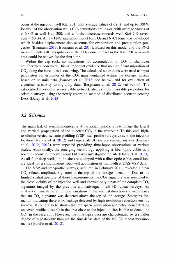
The second 3D repeat survey was acquired in autumn 2012 after 61 kt CO2
injected in the storage formation. The data were time-lapse processed and amplitudevariations were extracted for the top of the Stuttgart Formation. The lateral distri-bution of time-lapse amplitudes at the top of the Stuttgart Formation shows a highdegree of anisotropic propagation and confirms several features of propagationdetected by the first repeat survey (2009) which is shown in Fig. 8. After theinjection of 61 kt the CO2 could be imaged with a west-east extension of about700 m in autumn 2012 (Fig. 8, right).
For seismic reservoir monitoring, the use of fiber optic cables is currentlydiscussed as an emerging technology with considerable potential of replacingconventional wireline-based seismic acquisition in boreholes and also in surfaceapplications (Parker et al. 2014). In May 2013, a simultaneous DAS-VSP surveywas acquired using 23 vibro points and acquiring the seismic wave field along thefiber optic cable deployed in four wells and with a spatial sampling of 1 m. Thesurvey was performed within 4 days. The acquired DAS-VSP shot gathers showclear onsets of the downgoing compressional wave and of reflected upgoing waves.The data acquired in this survey are the basis for a high-resolution 3D imaging ofthe reservoir layer between the injection and monitoring wells of the Ketzin pilotsite.
Fig. 8 Map displaying the normalized time-lapse amplitudes at the top of the Stuttgart Formationfor the first 3D repeat survey in 2009 (left) and the second repeat survey in 2012 (right). Time-lapse amplitudes exceeding a background noise level of 0.3 are displayed in grey-scales. Thelocation of the injection well (Ktzi 201) is indicated by a white circle. For the comparison of thelateral extents of the CO2 in 2009 and 2012, the contour of the 2009 image (black line) has beenprojected onto the 2012 image
Joint Research Project CO2MAN (CO2MAN Reservoir Management) … 11
3.3 Geoelectrics
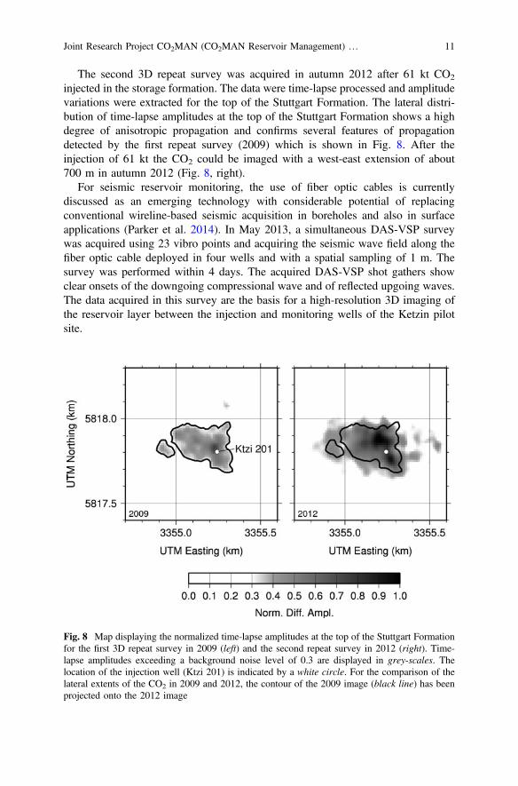
The geoelectrical monitoring programme at Ketzin comprised direct current (DC)geoelectric measurements in three different setups: (1) surface-to-surface, (2) sur-face-to-downhole and (3) crosshole data acquisition. The first two setups wereperformed as dipole-dipole measurements on two crossed profiles (length *4.8 kmeach of them) and two sparsely settled rings with radii of 0.8 km and 1.5 km,respectively. In addition, the setups (2) and (3) made use of 45 electrodes perma-nently installed in the wells Ktzi 200, Ktzi 201 and Ktzi 202 (Fig. 9).
At a detection level of about *600 t of injected CO2 the geoelectric measure-ments indicated relevant subsurface resistivity changes associated with the
Fig. 9 a Schematic of the DC geoelectric measurement concept at the Ketzin pilot site. Large-scale surveys were acquired in 2008, 2009, 2011 and 2012. Weekly-measured crosshole surveyswere conducted in the wells Ktzi 200, Ktzi 201 and Ktzi 202 (see inlay for the borehole distances).The major results are: b 3D resistivity distribution from inversion of the crossed profiles and thesurface-downhole survey in 2011, c Resistivity change (repeat 3/2009 vs. baseline) fromconstrained inversion of surface-downhole data (modified after Bergmann et al. 2014), andd Corresponding crosshole results in the major observation plane Ktzi 200–Ktzi 201
12 S. Martens et al.
migration of CO2 in a depth of about 630 m. The measured resistivity contrast wasin consistency with laboratory measurements on Ketzin sandstone core samples,where Archie fluid substitution revealed a resistivity increase of a factor of about 3(Kiessling et al. 2010). The permanent downhole electrode array was the subject ofengineering developments, such as modular system components, automated opti-mization of data pre-processing and remote-controlled data acquisition in order toachieve the operational requirements of CO2 storage sites. From the weekly-mea-sured crosshole data (Schmidt-Hattenberger et al. 2012) and the periodicallymeasured large-scale surface-downhole surveys (Bergmann et al. 2012) consistenttime-lapse images of the CO2 plume migration were derived which correlated fairlywell with other monitoring results obtained from seismic surveys, borehole loggingand geochemical data.
As a promising tool of geophysical data integration, a structurally constrainedinversion approach was applied that incorporates seismic structural information as apriori information into the resistivity inversion (Bergmann et al. 2014). Theresulting time-lapse resistivity signature of the constrained inversion was found tocollocate clearer with the time-lapse signature from the repeated 3D seismicinvestigations. The asymmetrical extension of this signature indicates preferentialCO2 migration towards the northwest direction which was also in good agreementwith the results from the seismic interpretation.
3.4 Gas Geochemistry
Long-term background data on the natural spatial and timely CO2 distribution andvariability are indispensable for a reliable monitoring and the detection of apotential leakage. In order to obtain this information for the Ketzin pilot site, gas-chemical and isotope investigations have been performed since 2005. Up to now,no indication of any CO2 leakage has been detected with this comprehensive gasmonitoring network system.
The monitoring network comprises 20 sampling locations for soil gas flux, soilmoisture and temperature measurements distributed across an area of approximately2 km × 2 km around the pilot site. In March 2011, eight permanent automated soilgas samplers were added in the direct vicinity of the boreholes together with ameteorological station. Since the start of injection in 2008, no change in soil CO2
gas flux could be detected as compared to the pre-injection baseline (Zimmer et al.2011a; Martens et al. 2013). Mean CO2 flux as averaged over all sampling locationsranged from 2.4 to 3.5 µmol/m2s for the pre-injection period and from 2.2 to2.5 µmol/m2s after the start of injection (Zimmer et al. 2011a). The spatial vari-ability of soil CO2 gas flux is 1.0–4.5 µmol/m2s for all sampling locations reflectingthe different organic carbon and nitrate contents, both serving as nutrients forbacterial life in the soil. The data show that soil temperature is the key factorcontrolling the biogenic CO2 production and subsequently the CO2 flux rate.
Joint Research Project CO2MAN (CO2MAN Reservoir Management) … 13
A U-tube system in the shallow observation well P300 enables above-zonemonitoring and the possible detection of a potential leakage through the first caprock at an earliest possible stage. Formation water from well P300 was permanentlysampled from a depth of 417 m (Exter Formation) and analyzed for dissolvedcations, anions, gases and 12C/13C isotope ratio of CO2 and revealed no impact ofthe injected CO2 on the Exter Formation.
From March 2010 to October 2011 a riser tube was installed in well Ktzi 200which allowed for continuous sampling and analyses of gas from 600 m depth. Themeasured gas composition was relatively constant with about 99 % CO2 and tracesof nitrogen, helium and methane. Two tracer tests were performed where bothkrypton and sulfur hexafluoride were added in the injection well Ktzi 201 in Mayand June 2011. Both gaseous tracers were detected in well Ktzi 200 after theinjection of 608 and 701 t of CO2, respectively, since the tracer test started. InOctober 2011 the riser tube was transferred to well Ktzi 202. The analyzed gascomposition from 600 m depth showed constant values until the end of the mea-surements in October 2013 and consists of 99.5 % CO2 with traces of nitrogen,helium and methane. Following the partial closure of the observation well Ktzi 202in autumn 2013, a gas membrane sensor (Zimmer et al. 2011b) for real timeobservation of gas at depth was installed at 500 m (21 m above the cement head) tomonitor the tightness of the cementation.
Since the beginning of the CO2 injection in 2008, stable isotope measurementshave been conducted for a detailed geochemical characterization of the reservoirand overlying formations, comprising δ13C and δ18O data of brine dissolvedinorganic carbon (DIC) and H2O (Nowak et al. 2013). Isotope measurements inconnection with gas tracer tests were also carried out when CO2 from the SchwarzePumpe oxyfuel pilot plant was used for injection in May and June 2011 (Martenset al. 2012). The δ13C of DIC proved to effectively trace the migration of theinjected CO2 at Ketzin (Myrttinen et al. 2010). When the δ13C CO2 isotopiccomposition of gas samples from the wellhead of Ktzi 201 and well Ktzi 200 wereanalyzed, a change in the 13C/12C composition of the CO2 was detected during thetemporary use of CO2 from Schwarze Pumpe (Martens et al. 2012).
4 Fluid Experiments and Processes in the StorageReservoir
In order to examine the potential interactions between injected CO2, formationfluid, the storage system and its microbial community at the Ketzin pilot site,laboratory experiments and investigations of samples from the site were carried out.On the one hand, the processes occurring in the reservoir should be characterizedand quantified. On the other hand measurements were taken to monitor theseprocesses. The main focus was on the study of fluid, gas and rock samples from
14 S. Martens et al.
Ketzin, especially from the newly drilled observation well Ktzi 203. The work onthe natural samples was supplemented by experimental studies under defined lab-oratory conditions.
4.1 Fluid Experiments and Petrophysics
Geochemical experiments on the fractionation of Fe, Cu and Zn between CO2 andformation fluid showed that CO2 acts as a solvent for trace elements and mobilizessmall but measurable amounts of Fe, Cu, Zn regardless of the CO2 density. By CO2
dissolved organic compounds act as potential complexing agents and increased theextraction ability for trace elements. In terms of long-term CO2 storage, thepotential consequences of these results include the precipitation of carbonateminerals in shallower, more distal regions of the aquifer and the transferal of metalsto adjacent aquifer systems (Rempel et al. 2011).
Several batch experiments under in situ conditions have been performed usingCO2, formation fluid and rock samples from Ketzin wells (Ktzi 201, 202). Resultsneither show clear changes nor uniform trends over time (up to 40 months) withregard to porosity, pore-size distribution, capillary pressure or geomechanicalparameters. Nuclear magnetic resonance (NMR) spectroscopy and mercury injec-tion porosimetry (MIP) were used to characterize samples before and after exper-iments. For two core sets geomechanical parameters were determined before andafter CO2 treatment. Baseline measurements are consistent with porosity loggingdata of corresponding wells and show high variability due to the heterogeneouslithology of the Stuttgart Formation. This natural variability of the reservoir ham-pers the comparability of whole rock samples before and after the experiments.Nonetheless, several lines of evidence indicate that mineralogical-geochemicalchanges occur due to CO2 exposure; but these are quantitatively subordinate. Inconclusion, effects of injected CO2 on the reservoir system integrity are minor(Fischer 2013; Fischer et al. 2013).
Porosity measurements on core samples recovered before the injection and thecorresponding NMR log (Ktzi 201) compared with porosity measurements ofapproximately 100 cores of the newly drilled well Ktzi 203 (gained after about4 years of CO2 exposure) show that the impact of CO2 injection on pore size relatedproperties of reservoir and cap rocks is minor and within the natural variability(Fig. 10). The variation of the porosity estimated by different methods is generallylow for the corresponding depths of the lithological sections. The mineralogicalinvestigations on the samples show also no significant dissolution or precipitationof minerals and find only minor quantities (usually < 2 vol%) of various species ofnewly precipitated carbonates with three potential CO3
2− sources: dolomite dis-solution, reactions of injected CO2 with the formation fluid, and the drill mud (Bocket al. 2013). The influence of the potash-containing drilling fluid of the well Ktzi203 could be determined by porosity investigation on twin samples from inner andouter parts of the cores. Especially for porous outer core samples NMR core
Joint Research Project CO2MAN (CO2MAN Reservoir Management) … 15
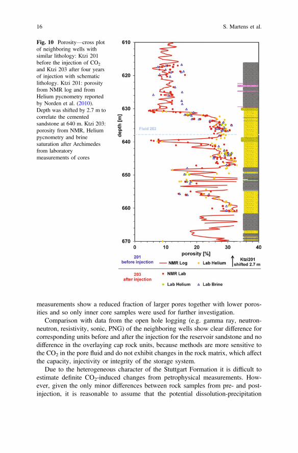
measurements show a reduced fraction of larger pores together with lower poros-ities and so only inner core samples were used for further investigation.
Comparison with data from the open hole logging (e.g. gamma ray, neutron-neutron, resistivity, sonic, PNG) of the neighboring wells show clear difference forcorresponding units before and after the injection for the reservoir sandstone and nodifference in the overlaying cap rock units, because methods are more sensitive tothe CO2 in the pore fluid and do not exhibit changes in the rock matrix, which affectthe capacity, injectivity or integrity of the storage system.
Due to the heterogeneous character of the Stuttgart Formation it is difficult toestimate definite CO2-induced changes from petrophysical measurements. How-ever, given the only minor differences between rock samples from pre- and post-injection, it is reasonable to assume that the potential dissolution-precipitation
Fig. 10 Porosity—cross plotof neighboring wells withsimilar lithology: Ktzi 201before the injection of CO2
and Ktzi 203 after four yearsof injection with schematiclithology. Ktzi 201: porosityfrom NMR log and fromHelium pycnometry reportedby Norden et al. (2010).Depth was shifted by 2.7 m tocorrelate the cementedsandstone at 640 m. Ktzi 203:porosity from NMR, Heliumpycnometry and brinesaturation after Archimedesfrom laboratorymeasurements of cores
16 S. Martens et al.