Embed Size (px)
Citation preview

1
Distal Lateral Femur
Operative Technique
AxSOSLocking Plate System
2
Introduction
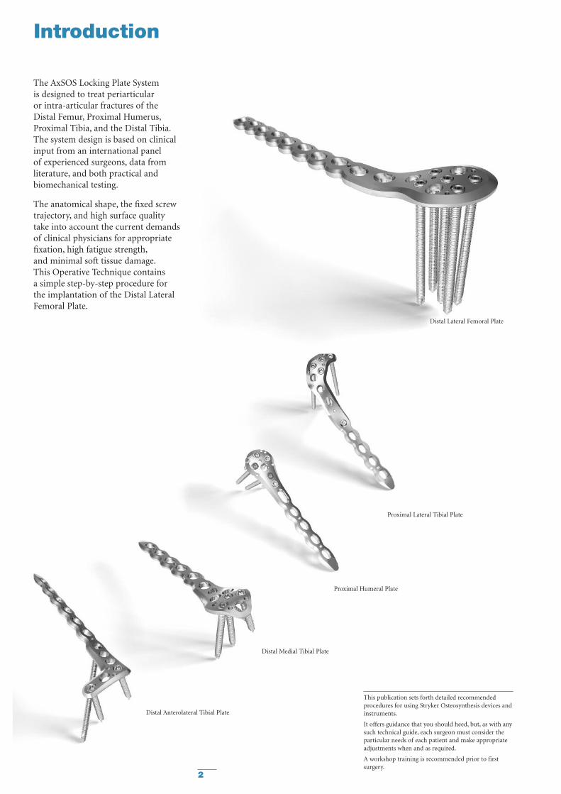
Distal Medial Tibial Plate
Distal Anterolateral Tibial Plate
Proximal Lateral Tibial Plate
Distal Lateral Femoral Plate
Proximal Humeral Plate
The AxSOS Locking Plate Systemis designed to treat periarticularor intra-articular fractures of theDistal Femur, Proximal Humerus,Proximal Tibia, and the Distal Tibia.The system design is based on clinicalinput from an international panelof experienced surgeons, data fromliterature, and both practical andbiomechanical testing.
The anatomical shape, the fixed screwtrajectory, and high surface qualitytake into account the current demandsof clinical physicians for appropriatefixation, high fatigue strength,and minimal soft tissue damage.This Operative Technique containsa simple step-by-step procedure forthe implantation of the Distal LateralFemoral Plate.
This publication sets forth detailed recommendedprocedures for using Stryker Osteosynthesis devices andinstruments.
It offers guidance that you should heed, but, as with anysuch technical guide, each surgeon must consider theparticular needs of each patient and make appropriateadjustments when and as required.
A workshop training is recommended prior to firstsurgery.

3
Features & Benefits
System
• The Distal Femoral Plate is designedwith optimised fixed-angled screwtrajectories which provide improvedbiomechanical stability and betterresistance to pull out. The metaphysealscrew pattern also avoids anyinterference in the intercondylarnotch and helps prevent loss ofreduction.
Instruments
• Simple technique, easyinstrumentation with minimalcomponents.
• Compatible with MIPO (MinimallyInvasive Plate Osteosynthesis)technique using state of the artinstrumentation.
Range
• Longer plates cover a wider rangeof fractures.
Unthreaded Freedom Holes
• Freehand placement of screws.
• Lag Screw possibility.
Rounded & Tapered Plate Ends
• Helps facilitate sliding of platessub-muscularly.
K-Wire/Reduction holes
• Primary/temporary plate andfracture fixation.
Anatomically contoured
• Little or no bending required.
• Reduced OR time.
Shaft Holes - Standard or Locking
• Bi-directional shaft holes
• Compression, neutral or buttressfixation.
• Accept Standard 4.5/6.5mmSPS screws.
• Accept Locking Insert for axiallystable screws.
Innovative Locking Screw design
• The single thread screw designallows easy insertion into the plate,reducing any potential for crossthreading or cold welding.
Monoaxial holes (5)
• Allow axially stable screw placement,bringing rigidity to construct.
Aiming Block
• Facilitates the placement of theDrill Sleeve.
‘Waisted’ plate shape
• Uniform load transfer.
Relative Indications & Contraindications
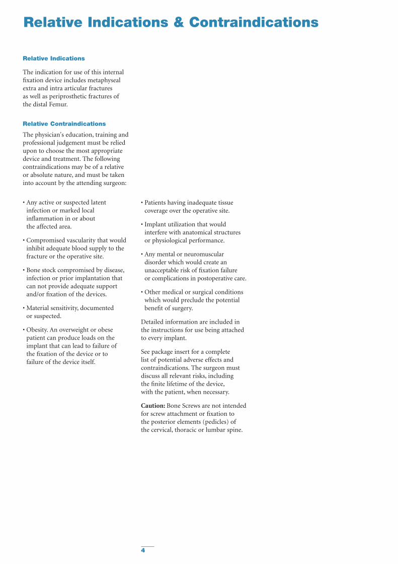
Relative Indications
The indication for use of this internalfixation device includes metaphysealextra and intra articular fracturesas well as periprosthetic fractures ofthe distal Femur.
Relative Contraindications
The physician's education, training andprofessional judgement must be reliedupon to choose the most appropriatedevice and treatment. The followingcontraindications may be of a relativeor absolute nature, and must be takeninto account by the attending surgeon:
• Any active or suspected latentinfection or marked localinflammation in or aboutthe affected area.
• Compromised vascularity that wouldinhibit adequate blood supply to thefracture or the operative site.
• Bone stock compromised by disease,infection or prior implantation thatcan not provide adequate supportand/or fixation of the devices.
• Material sensitivity, documentedor suspected.
• Obesity. An overweight or obesepatient can produce loads on theimplant that can lead to failure ofthe fixation of the device or tofailure of the device itself.
• Patients having inadequate tissuecoverage over the operative site.
• Implant utilization that wouldinterfere with anatomical structuresor physiological performance.
• Any mental or neuromusculardisorder which would create anunacceptable risk of fixation failureor complications in postoperative care.
• Other medical or surgical conditionswhich would preclude the potentialbenefit of surgery.
Detailed information are included inthe instructions for use being attachedto every implant.
See package insert for a completelist of potential adverse effects andcontraindications. The surgeon mustdiscuss all relevant risks, includingthe finite lifetime of the device,with the patient, when necessary.
Caution: Bone Screws are not intendedfor screw attachment or fixation tothe posterior elements (pedicles) ofthe cervical, thoracic or lumbar spine.
4

5
Operative Technique
Patient Positioning: Supine with option to flex the knee up to 60° over a leg support. Visualization of
the distal femur under fluoroscopy in both the lateral and AP views is necessary.
Surgical Approach: Standard Lateral, Modified Lateral or Lateral Parapatellar approach.
Instrument/Screw Set: 5.0mm
Reduction
Anatomical reduction of the fractureshould be performed either by directvisualization with the help ofpercutaneous clamps, or alternatively abridging external fixator can aid withindirect reduction to correct thelength, rotation, recurvatum andvarus-valgus.
Fracture reduction of the articularsurface should be confirmed by directvisualization, or fluoroscopy.Use K-Wires and/or lag screws asnecessary to temporarily secure thereduction. Typically, K-Wires setparallel to the joint axis will not onlyact to hold and support the reduction,but also help to visualize/identify thejoint.
Care must be taken that these do notinterfere with the required plate andscrew positions. Consideration mustalso be taken when positioningindependent lag screws prior to plateplacement to ensure that they do notinterfere with the planned platelocation or Locking Screw trajectories.
If any large bony defects are presentthey should be filled by either bonegraft or bone substitute material.
Note: If a sub-muscular techniquehas been used please see the relevantsection later in this Guide.
Bending
In most cases the pre-contoured platewill fit without the need for furtherbending. However, should additionalbending of the plate be required(generally at the junction from themetaphysis to the shaft) the Table PlateBender (REF 702900) should be used.Bending of the plate in the region ofthe metaphyseal locking holes willaffect the ability to correctly seatthe Locking Screws into the plateand is therefore not permitted.Plate contouring in the shaft regionshould be restricted to the areabetween the shaft holes.Plate contouring will affect the abilityto place a Locking Insert into the shaftholes adjacent to the bending point.
General Guidelines

6
Operative Technique
Measurement Options
Conventional direct
Measure off K-Wire Read off Calibration
Measure off Drill
General Guidelines
Locking Screw Measurement
There are four options to obtainthe proper Locking Screw lengthas illustrated below.
Correct Screw Selection
Select a screw approximately 2-3mmshorter than the measured length toavoid screw penetrations through themedial cortex in metaphyseal fixation.
Add 2-3mm to measured length foroptimal bi-cortical shaft fixation.

7
Step 1 – Pre Operative Planning
Use of the X-Ray Template(REF 981094) or Plate Trial(REF 702791) in association withfluoroscopy can help to assist in theselection of an appropriately sizedimplant (Fig. 1).
If the Plate Trial is more than 90mmaway from the bone, e.g. with obesepatients, a magnification factor of10-15% will occur and must becompensated for. Final intraoperativeverification should be made to ensurecorrect implant selection.
Operative Technique
Fig. 1
M-L ViewA-P View
LeftRight
Scale: 1.15 : 1Magnification: 15%
AxSOS™ Locking Plate SystemDistal Lateral Femoral Plate
Please Note:
Due to the multi-planar positioning of the screws thedetermination of the corresponding screw length andangle is difficult by means of single planar x-rays ingeneral.All dimensions resulting from the use of this templatehas to be verified intraoperatively, to ensure properimplant selection.
4 Hole
6 Hole
8 Hole
10 Hole
12 Hole
14 Hole
16 Hole
Ø 5mm Locking Screw, Self TappingREF 370314/-395
Ø 5mm Periprosthetic Locking Screw, Self TappingREF 370110/-120
Ø 4.5mm Cortical Screw, Self TappingREF 340614/-695
Ø 6.5mm Cancellous ScrewPartial Thread 16mm: REF 341060/-095Partial Thread 32mm: REF 342060/-095Full Thread: REF 343060/-095
REF 981094 Rev. 0
8
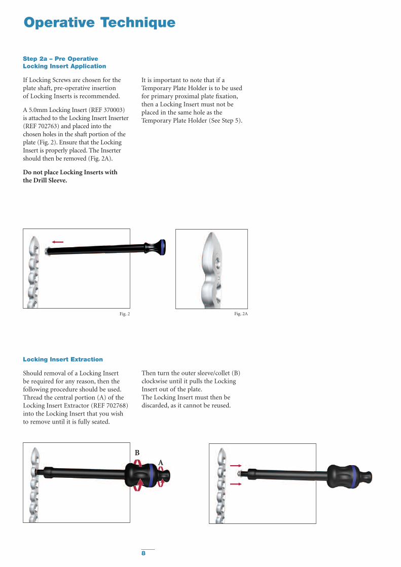
Step 2a – Pre OperativeLocking Insert Application
If Locking Screws are chosen for theplate shaft, pre-operative insertionof Locking Inserts is recommended.
A 5.0mm Locking Insert (REF 370003)is attached to the Locking Insert Inserter(REF 702763) and placed into thechosen holes in the shaft portion of theplate (Fig. 2). Ensure that the LockingInsert is properly placed. The Insertershould then be removed (Fig. 2A).
Do not place Locking Inserts withthe Drill Sleeve.
It is important to note that if aTemporary Plate Holder is to be usedfor primary proximal plate fixation,then a Locking Insert must not beplaced in the same hole as theTemporary Plate Holder (See Step 5).
Fig. 2 Fig. 2A
Operative Technique
Locking Insert Extraction
Should removal of a Locking Insertbe required for any reason, then thefollowing procedure should be used.Thread the central portion (A) of theLocking Insert Extractor (REF 702768)into the Locking Insert that you wishto remove until it is fully seated.
Then turn the outer sleeve/collet (B)clockwise until it pulls the LockingInsert out of the plate.The Locking Insert must then bediscarded, as it cannot be reused.
BA
9
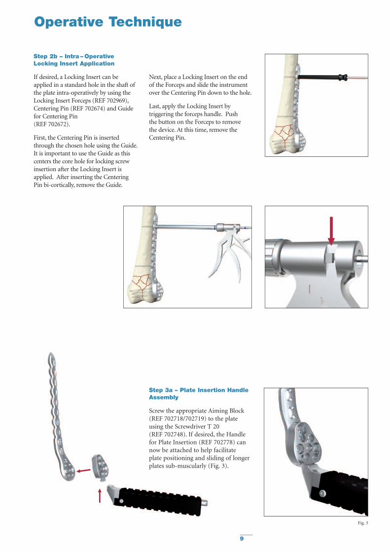
Step 3a – Plate Insertion HandleAssembly
Screw the appropriate Aiming Block(REF 702718/702719) to the plateusing the Screwdriver T 20(REF 702748). If desired, the Handlefor Plate Insertion (REF 702778) cannow be attached to help facilitateplate positioning and sliding of longerplates sub-muscularly (Fig. 3).
Fig. 3
Operative Technique
Step 2b – Intra – OperativeLocking Insert Application
If desired, a Locking Insert can beapplied in a standard hole in the shaft ofthe plate intra-operatively by using theLocking Insert Forceps (REF 702969),Centering Pin (REF 702674) and Guidefor Centering Pin(REF 702672).
First, the Centering Pin is insertedthrough the chosen hole using the Guide.It is important to use the Guide as thiscenters the core hole for locking screwinsertion after the Locking Insert isapplied. After inserting the CenteringPin bi-cortically, remove the Guide.
Next, place a Locking Insert on the endof the Forceps and slide the instrumentover the Centering Pin down to the hole.
Last, apply the Locking Insert bytriggering the forceps handle. Pushthe button on the Forceps to removethe device. At this time, remove theCentering Pin.

10
Step 3b – Plate Application
After the skin incision is performedand anatomical reduction is achieved,apply the plate to the lateral condyle.The proper position is when the distaland anterior margin of the plate isapprox. 10mm from the articularsurface. (Fig. 4).
This helps to ensure that the mostdistal Locking Screws are directlysupporting the joint surface.
Step 4 – Primary Plate Fixation –Distal
The K-Wire holes in the metaphysealPart of the plate allow for temporaryplate fixation to the articular block.(Fig. 5).
Remove the Handle for Insertion bypressing the metal button at the endof the Handle.
Using the K-Wire Sleeve (REF 702703)in conjunction with the Drill Sleeve(REF 702708), a 2.0 x 285mm K-Wirecan now be inserted into one of thedistal Locking Screw holes (Fig. 6A).This wire should be parallel to thejoint line to assure proper alignment ofthe distal femur.
This step also shows the position of alater placed screw and shows itsrelation to the joint surface.Furthermore, it will confirm the screwwill not be placed intra-articularly.
Using fluoroscopy, the position of thisK-Wire can be checked until theoptimal position is achieved and theplate is correctly positioned.Correct proximal placement shouldalso be re-confirmed at this point tomake sure the plate shaft is properlyaligned over the lateral surface of thefemoral shaft (Fig. 6B).
If the distal and axial alignment of theplate cannot be achieved, the K-Wiresshould be removed, the platereadjusted, and the above procedurerepeated until both the K-Wire and theplate are in the desired position.
Operative Technique
Fig. 4 – Lateral View
Fig. 6A – AP View
Fig. 5 – AP View Fig. 5 – Lateral View
Fig. 4 – AP View
Fig. 6B – Lateral View
Additional K-Wires can be inserted inthe K-Wire holes around the lockingholes to further help secure the plateto the bone and also support depressedareas in the articular surface. Do notremove the Drill Sleeve and K-WireSleeve at this point as it will cause aloss of the plate position or reduction.

11
Step 5 – Primary Plate Fixation –Proximal
The proximal end of the plate mustnow be secured. This can be achievedthrough one of four methods:
• A K-Wire inserted in the shaftK-Wire holes.
• A 4.5mm Cortical Screw usingthe standard technique.
• A 5.0mm Locking Screw witha Locking Insert(see Step 7 – Shaft Locking).
• The Temporary Plate Holder(REF 702776).
Using a 3.2mm Drill (REF 700357)and Double Drill Guide (REF 702417),drill a core hole through both corticesin the hole above the most proximalfracture line.
The length is then measured usingthe Depth Gauge for Standard Screws(REF 702877) and an appropriateSelf-Tapping 4.5mm Cortical Screwis then inserted using Screwdriver(REF 702843) (Fig. 7).
The Temporary Plate Holder(REF 702776) has a self drilling,self tapping tip for quick insertion intocortical bone. To help prevent thermalnecrosis during the drilling stage,it is recommended that this device isinserted by hand. Once the device hasbeen inserted through the far cortex,the threaded outer sleeve/collet isturned clockwise until it pushes theplate to the bone (Fig. 8).
The core diameter of this instrumentis 2.4mm to allow a 4.5mm CorticalScrew to be subsequently inserted inthe same shaft hole (overdrill hole with3.2mm Drill (REF 700357)).
Note: A Locking Insert and LockingScrew should not be used in the holewhere the Temporary Plate Holderis used.
Step 6 – Metaphyseal Locking
Locking Screws cannot act as LagScrews. Should an interfragmentarycompression effect be required in casesof intercondylar splits, 6.5mm StandardCancellous Screws or 4.5mm CorticalScrews must first be placed in theunthreaded metaphyseal plate holes(Fig. 9) prior to the placementof any Locking Screws. Using the4.5mm end of the Double Drill Guide(REF 702417), the near cortex isoverdrilled to accept the shaft orthe thread of the Lag Screw.Use the other end of the Drill Guideto drill the core diameter (3.2mm).Measure the length of the screw usingthe Depth Gauge for Standard Screws(REF 702877), and pre-tap the nearcortex with the Tap (REF 702807)if a Cancellous Screw has been selected.Consideration must also be taken whenpositioning these screws to ensure thatthey do not interfere with the givenLocking Screw trajectories (Fig.10).
Operative Technique
Fig. 9
Fig. 7 Fig. 8
Fig. 10

12
Fig. 11
Operative Technique
Locking Screws should initially beinserted manually to ensure properalignment.
If the Locking Screw thread does notimmediately engage in the platethread, reverse the screw a few turnsand re-insert the screw once itis properly aligned.
Final tightening of Locking Screwsshould always be performed manuallyusing the Torque Limiting Attachment(REF 702751) together with the SolidScrewdriver T20 (REF 702754) andT-Handle (REF 702430) (Fig. 13).This helps to prevent over-tighteningof Locking Screws, and also ensuresthat these Screws are tightened to atorque of 5.0Nm. The device will clickwhen the torque reaches 5Nm.
Note: The Torque Limiters requireroutine maintainance. Refer tothe Instructions forMaintainance of Torque Limiters(REF V15020).
Fixation of the metaphyseal portion ofthe plate can be started using the presetK-Wire in the distal locking hole asdescribed in Step 4.
The length of the screw can be takenby using the K-Wire side of the Drill/K-Wire Depth Gauge (REF 702712)(See Locking Screw MeasurementGuidelines on Page 6). Remove theK-Wire and K-Wire Sleeve leaving theDrill Sleeve in Place.
A 4.3mm Drill (REF 702743) is thenused to drill the core hole for theLocking Screw (Fig. 11).Using fluoroscopy, check the correctdepth of the drill, and measure thelength of the screw. The Drill Sleeveshould now be removed, and thecorrect length 5.0mm Locking Screwis inserted using the Screwdriver T20and Screw Holding Sleeve(REF 702733) (Fig. 12).
Fig. 13
If inserting Locking Screws underpower, make sure to use a low speedto avoid damage to the screw/plateinterface, and perform final tighteningby hand, as described above.The remaining proximal LockingScrews are inserted following the sametechnique with or without the use aK-Wire.
Always use the Drill Sleeve(REF 702708) when drillingfor Locking holes.
To ensure maximum stability, it isrecommended that all locking holesare filled with a Locking Screw of theappropriate length.
Fig. 12
Note: Ensure that the screwdriver tipis fully seated in the screw head, butdo not apply axial force during finaltightening

13
Operative Technique
Option 2 – Locking Screws
5.0mm Locking Screws can be placedin a shaft hole provided there is apre-placed Locking Insert in the hole.(See Step 1 or 2a).
The Drill Sleeve(REF 702708) isthreaded into the Locking Insert toensure initial fixation of the LockingInsert into the plate. This will alsofacilitate subsequent screw placement.A 4.3mm Drill Bit (REF 702743) isused to drill through both cortices(Fig. 14).
Avoid any angulation or excessiveforce on the drill, as this coulddislodge the Locking Insert.
The screw measurement is then taken.The appropriate sized Locking Screwis then inserted using the SolidScrewdriver T20 (REF 702754) andthe Screw Holding Sleeve (REF 702733)together with the Torque LimitingAttachment (REF 702751) andthe T-Handle (REF 702430).
Note: Ensure that the screwdriver tipis fully seated in the screw head, butdo not apply axial force during finaltightening.
This procedure is repeated for allholes chosen for locked shaft fixation.All provisional plate fixation devices(K-Wires, Temporary Plate Holder, etc)can now be removed.
Option 1 – Standard Screws
4.5mm Standard Cortical Screws canbe placed in neutral, compression orbuttress positions as desired using thestandard technique. These screws canalso act as lag screws.
Step 7 – Shaft Fixation
The shaft holes of this plate have beendesigned to accept either 4.5mmStandard Cortical Screws or 5.0mmLocking Screws together with thecorresponding Locking Inserts.
If a combination of Standard andLocking Screws is used in the shaft,then the Standard Cortical Screwsmust be placed prior to the LockingScrews.
Fig. 11
Buttress
Compression
Neutral Drill Sleeve Handle
20° Transverse Angulation70° Axial AngulationLocked Hole
Fig.15
Fig. 14

14
Fig. 18
Fig. 17
Operative Technique
Sub-Muscular Insertion Technique
When implanting longer plates,a minimally invasive technique canbe used. The Soft Tissue Elevator(REF 702782) can be used to createa pathway for the implant (Fig. 15).
The plate has a special rounded andtapered end, which allows a smoothinsertion under the soft tissue(Fig. 16).
Fig. 15 Fig. 16
Additionally, the Shaft Hole Locatorcan be used to help locate the shaftholes. Attach the appropriate side of theShaft Hole Locator (REF 702791) bysliding it over the top of the Handleuntil it seats in one of the grooves at aappropriate distance above the skin(Fig. 17 - 18). The slot and markings onthe Shaft Hole Locator act as a guide tothe respective holes in the plate.

15
Percutaneous Screw Insertion
A small stab incision can then be madethrough the slot to locate the holeselected for screw placement. The ShaftHole Locator can then be rotated outof the way or removed.
The Standard Percutaneous DrillSleeve (REF. 702710) or the NeutralPercutaneous Drill Sleeve(REF 702958) in conjunction withthe Drill Sleeve Handle (REF 702822)can be used to assist with drilling forStandard Screws. Use a 3.2mmdrill bit (REF 700357).
With the aid of the Soft TissueSpreader (REF 702918), the skin canbe opened to form a small window(Fig. 19–20) through which eithera Standard Screw or Locking Screw(provided a Locking Insert is present)can be placed. For Locking Screwinsertion, use the threaded DrillSleeve (REF 702708) together withthe 4.3mm drill bit (REF 702743)to drill the core hole.
Fig. 20Fig. 19
Operative Technique

16
Fig. 22 Fig. 23Fig. 21
Fig. 25Fig. 24
Periprosthetic Solution
Should the plate be used inconjunction with cables, e.g. withperiprosthetic fractures, The CablePlug (REF 370005) can be used.This Cable Plug fits into the shaft plateholes (Fig. 24) and facilitates a preciseand stable platform to support a CableCrimp. A range of shorter blunt endedPeriprosthetic Locking Screws (Fig. 25)are also available when a prosthesis ispresent. If these Periprosthetic LockingScrews are chosen for the plate shaft,pre-operative insertion of LockingInserts is recomended.
Operative Technique
Final plate and screw positions areshown in Figures 21–23.

17
Tips & Tricks
1. Always use the threaded Drill Sleevewhen drilling for Locking Screws(threaded plate hole or LockingInsert).
Free hand drilling will lead to amisalignment of the Screw andtherefore result in screw jammingduring insertion. It is essential, to drillthe core hole in the correct trajectoryto facilitate accurate insertion of theLocking Screws.
If the Locking Screw thread does notimmediately engage the plate thread,reverse the screw a few turns andre-insert the screw once it is properlyaligned.
2. Always start inserting the screwmanually to ensure properalignment in the plate thread andthe core hole.It is recommended to start insertingthe screw using “the two fingertechnique” on the Teardrop handle.Avoid any angulations or excessiveforce on the screwdriver, as thiscould cross-thread the screw.
Power can negatively affect screwinsertion, if used improperly,damaging the screw/plate interface(screw jamming). This can lead toscrew heads breaking or being stripped.
Again, if the Locking Screw does notadvance, reverse the screw a few turns,and realign it before you startre-insertion.
3. If power insertion is selected aftermanual start (see above), use lowspeed only, do not apply axialpressure, and never “push” thescrew through the plate!
Allow the single, continuousthreaded screw design to engage theplate and cut the thread in the boneon its own, as designed.
Stop power insertion approximately1cm before engaging the screw headin the plate.
4. It is advisable to tap hard (dense)cortical bone before inserting aLocking Screw. Use low-speedsetting for power tapping.
5. Do not use power for finalinsertion of Locking Screws.It is imperative to engage the screwhead into the plate using the TorqueLimiting Attachment. Ensure thatthe screwdriver tip is fully seated inthe screw head, but do not applyaxial force during final tightening.
If the screw stops short of finalposition, back up a few turnsand advance the screw again(with torque limiter on).
The spherical tip of the Tap preciselyaligns the instrument in the predrilledcore hole during thread cutting.This will facilitate subsequent screwplacement.

18
Ordering Information - Implants
Stainless Steel Plate Shaft LockingREF Length Holes Holes
Left Right mm
436504 436524 130 4 5436506 436526 166 6 5436508 436528 202 8 5436510 436530 238 10 5436512 436532 274 12 5436514 436534 310 14 5436516 436536 343 16 5
Stainless Steel SystemREF mm
370003 5.0
DISTAL LATERAL FEMURLocking Screws Ø5.0mmStandard Screws Ø4.5, 6.5mm
5.0MM LOCKING INSERT
Stainless Steel SystemREF mm
370005 5.0
5.0MM CABLE PLUG
Note: For Sterile Implants, add ‘S’ to REF

Stainless Steel ScrewREF Length mm
370314 14370316 16370318 18370320 20370322 22370324 24370326 26370328 28370330 30370332 32370334 34370336 36370338 38370340 40370342 42370344 44370346 46370348 48370350 50370355 55370360 60370365 65370370 70370375 75370380 80370385 85370390 90370395 95
Stainless Steel ScrewREF Length mm
340614 14340616 16340618 18340620 20340622 22340624 24340626 26340628 28340630 30340632 32340634 34340636 36340638 38340640 40340642 42340644 44340646 46340648 48340650 50340655 55340660 60340665 65340670 70340675 75340680 80340685 85340690 90340695 95
5.0MM LOCKING SCREW, SELF TAPPINGT20 DRIVE
4.5MM CORTICAL SCREW, SELF TAPPING3.5MM HEX DRIVE
Ordering Information - Implants
5.0MM PERIPROSTHETIC LOCKING SCREW, SELF TAPPINGT20 DRIVE
Stainless Steel ScrewREF Length mm
341060 60341065 65341070 70341075 75341080 80341085 85341090 90341095 95
Stainless Steel ScrewREF Length mm
342060 60342065 65342070 70342075 75342080 80342085 85342090 90342095 95
Stainless Steel ScrewREF Length mm
343060 60343065 65343070 70343075 75343080 80343085 85343090 90343095 95
6.5MM CANCELLOUS SCREW, 16MM THREAD3.5MM HEX DRIVE
6.5MM CANCELLOUS SCREW, 32MM THREAD3.5MM HEX DRIVE
6.5MM CANCELLOUS SCREW, FULL THREAD3.5MM HEX DRIVE
Stainless Steel ScrewREF Length mm
370110 10370112 12370114 14370116 16370118 18370120 20
Note: For Sterile Implants, add ‘S’ to REF
19

20
REF Description
5.0mm Locking Instruments
702743 Drill Ø4.3mm x 262mm
702773 Tap Ø5.0mm x 140mm
702748 Screwdriver T20, L300mm
702754 Solid Screwdriver T20, L180mm
702733 Screw Holding Sleeve
702703 K-wire Sleeve
702708 Drill Sleeve
702884 Direct Depth Gauge for Locking Screws
702751 Torque Limiter T20/5.0mm
702763 Locking Insert Inserter 5.0mm
702430 T-Handle medium, AO Fitting
390191 K-wire 2.0mm x 285mm
702768 Locking Insert Extractor
702778 Handle for Plate Insertion
702712 Drill/K-Wire Measure Gauge
702776 Temporary Plate Holder
702776-1 Spare Shaft for Temporary Plate Holder
702918 Soft Tissue Spreader
702962 Trocar (for Soft Tissue Spreader)
702782 Soft Tissue Elevator
Ordering Information - 5.0mm Instruments
Ordering Information - 5.0mm Instruments
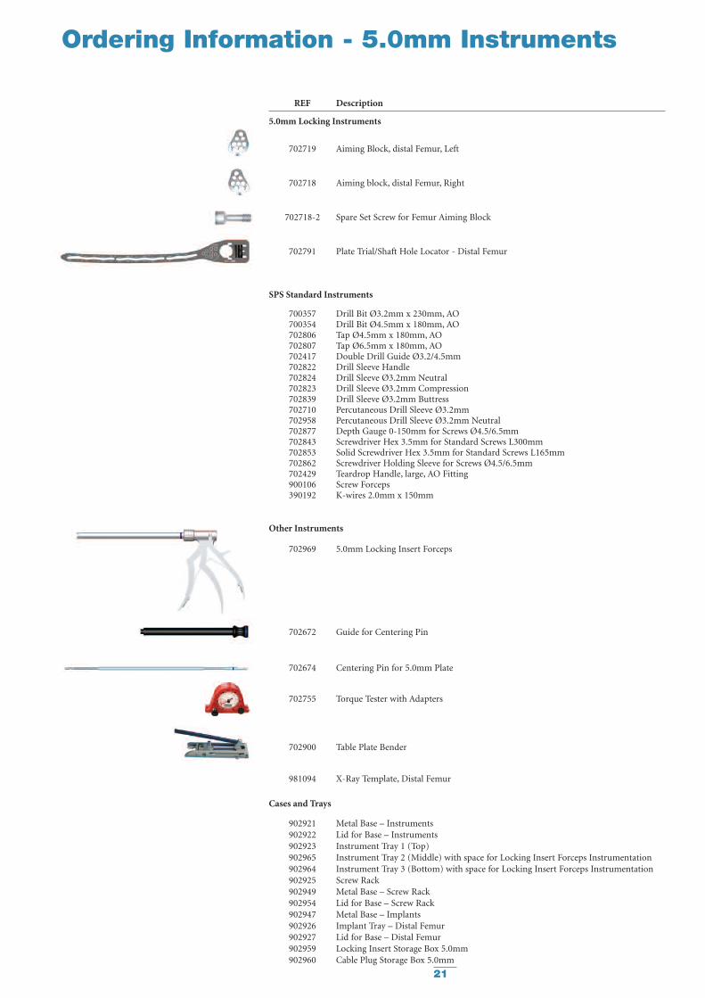
REF Description
5.0mm Locking Instruments
702719 Aiming Block, distal Femur, Left
702718 Aiming block, distal Femur, Right
702718-2 Spare Set Screw for Femur Aiming Block
702791 Plate Trial/Shaft Hole Locator - Distal Femur
SPS Standard Instruments
700357 Drill Bit Ø3.2mm x 230mm, AO700354 Drill Bit Ø4.5mm x 180mm, AO702806 Tap Ø4.5mm x 180mm, AO702807 Tap Ø6.5mm x 180mm, AO702417 Double Drill Guide Ø3.2/4.5mm702822 Drill Sleeve Handle702824 Drill Sleeve Ø3.2mm Neutral702823 Drill Sleeve Ø3.2mm Compression702839 Drill Sleeve Ø3.2mm Buttress702710 Percutaneous Drill Sleeve Ø3.2mm702958 Percutaneous Drill Sleeve Ø3.2mm Neutral702877 Depth Gauge 0-150mm for Screws Ø4.5/6.5mm702843 Screwdriver Hex 3.5mm for Standard Screws L300mm702853 Solid Screwdriver Hex 3.5mm for Standard Screws L165mm702862 Screwdriver Holding Sleeve for Screws Ø4.5/6.5mm702429 Teardrop Handle, large, AO Fitting900106 Screw Forceps390192 K-wires 2.0mm x 150mm
Other Instruments
702969 5.0mm Locking Insert Forceps
702672 Guide for Centering Pin
702674 Centering Pin for 5.0mm Plate
702755 Torque Tester with Adapters
702900 Table Plate Bender
981094 X-Ray Template, Distal Femur
Cases and Trays
902921 Metal Base – Instruments902922 Lid for Base – Instruments902923 Instrument Tray 1 (Top)902965 Instrument Tray 2 (Middle) with space for Locking Insert Forceps Instrumentation902964 Instrument Tray 3 (Bottom) with space for Locking Insert Forceps Instrumentation902925 Screw Rack902949 Metal Base – Screw Rack902954 Lid for Base – Screw Rack902947 Metal Base – Implants902926 Implant Tray – Distal Femur902927 Lid for Base – Distal Femur902959 Locking Insert Storage Box 5.0mm902960 Cable Plug Storage Box 5.0mm
21

22
Femoral Condyle Void Filling
Additional Information
Advantages
Injectable or Manual Implantation
HydroSet can be easily implanted viasimple injection or manual applicationtechniques for a variety of applications.
Fast Setting
HydroSet has been specificallydesigned to set quickly once implantedunder normal physiological conditions,potentially minimizing procedure time.
Isothermic
HydroSet does not release any heat asit sets, preventing potential thermalinjury.
Excellent Wet-FieldCharacteristics
HydroSet is chemically formulated toset in a wet field environmenteliminating the need to meticulouslydry the operative site prior toimplantation.2
Osteoconductive
The composition of hydroxyapititeclosely match that of bone mineralthus imparting osteoconductiveproperties.3
Augmentation of ProvisionalHardware during surgicalprocedure
HydroSet can be drilled and tapped toaccommodate the placement ofprovisional hardware.
Scanning Electron Microscope image of HydroSet materialcrystalline microstructure at 15000x magnification
HydroSet is an injectable, sculptableand fast-setting bone substitute.HydroSet is a calcium phosphatecement that converts to hydroxyapatite,the principle mineral component ofbone. The crystalline structure andporosity of HydroSet makes it aneffective osteoconductive andosteointegrative material, withexcellent biocompatibility andmechanical properties1. HydroSet wasspecifically formulated to set in a wetfield environment and exhibitsoutstanding wet-field characteristics.2
The chemical reaction that occurs asHydroSet hardens does not releaseheat that could be potentiallydamaging to the surrounding tissue.Once set, HydroSet can be drilledand tapped to augment provisionalhardware placement during thesurgical procedure. After implantation,the HydroSet is remodelled over timeat a rate that is dependent on the sizeof the defect and the average age andgeneral health of the patient.
Indications
HydroSet is a self-setting calciumphosphate cement indicated to fillbony voids or gaps of the skeletalsystem (i.e. extremities, craniofacial,spine, and pelvis). These defects maybe surgically created or osseous defectscreated from traumatic injury to thebone. HydroSet is indicated only forbony voids or gaps that are notintrinsic to the stability of the bonystructure.
HydroSet cured in situ provides anopen void/gap filler than can augmentprovisional hardware (e.g K-Wires,Plates, Screws) to help support bonefragments during the surgicalprocedure. The cured cement acts onlyas a temporary support media and isnot intended to provide structuralsupport during the healing process.
References1. Chow, L, Takagi, L. A Natural Bone Cement –
A Laboratory Novelty Led to the Development ofRevolutionary New Biomaterials. J. Res. Natl. Stand.Technolo. 106, 1029-1033 (2001).
2. 1808.E703. Wet field set penetration(Data on file at Stryker)
3. Dickson, K.F., et al. The Use of BoneSourceHydroxyapatite Cement for Traumatic MetaphysealBone Void Filling. J Trauma 2002; 53:1103-1108.
HydroSetInjectable HA
Note: For more detailed informationrefer to Literature No. 90-079001275
Note: Screw fixation mustbe provided by bone
Ordering Information
Ref Description397003 3cc HydroSet397005 5cc HydroSet397010 10cc HydroSet397015 15cc HydroSet

23

Stryker Trauma AGBohnackerweg 1CH-2545 SelzachSwitzerland
www.osteosynthesis.stryker.com
The information presented in this brochure is intended to demonstrate a Stryker product. Always refer to the packageinsert, product label and/or user instructions before using any Stryker product. Surgeons must always rely on their ownclinical judgment when deciding which products and techniques to use with their patients. Products may not be availablein all markets. Product availability is subject to the regulatory or medical practices that govern individual markets.Please contact your Stryker representative if you have questions about the availability of Stryker products in your area.
Stryker Corporation or its subsidiary owns the registered trademark: Stryker.Stryker Corporation or its subsidiary owns, uses or has applied for the following trademarks AxSOS.
US Patents Pending
Literature Number: 982277LOT D4507
Copyright © 2007 Stryker