Embed Size (px)
Citation preview
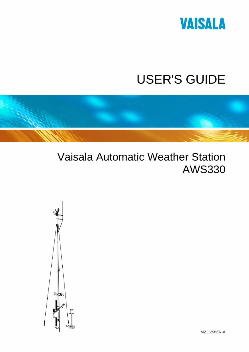
USER'S GUIDE
Vaisala Automatic Weather StationAWS330
M211296EN-A
PUBLISHED BY
Vaisala Oyj Phone (int.): +358 9 8949 1 P.O. Box 26 Fax: +358 9 8949 2227 FI-00421 Helsinki Finland
Visit our Internet pages at www.vaisala.com.
© Vaisala 2011
No part of this manual may be reproduced in any form or by any means, electronic or mechanical (including photocopying), nor may its contents be communicated to a third party without prior written permission of the copyright holder.
The contents are subject to change without prior notice.
Please observe that this manual does not create any legally binding obligations for Vaisala towards the customer or end user. All legally binding commitments and agreements are included exclusively in the applicable supply contract or Conditions of Sale.

________________________________________________________________________________
VAISALA ________________________________________________________________________ 1
Table of Contents
CHAPTER 1 GENERAL INFORMATION............................................................................ 9
About This Manual ................................................................... 9 Contents of This Manual ....................................................... 9 Version Information ............................................................. 10 Related Manuals ................................................................. 10 Documentation Conventions............................................... 10
Product-Related Safety Precautions .................................... 11 ESD Protection ....................................................................... 11 Recycling ................................................................................ 12 Regulatory Compliances ....................................................... 12 Trademarks ............................................................................. 12 License Agreement ................................................................ 12 Redistribution License Agreement....................................... 13 Warranty.................................................................................. 14
CHAPTER 2 PRODUCT OVERVIEW................................................................................ 15
Introduction to AWS330......................................................... 15 Product Nomenclature........................................................... 18
CHAPTER 3 FUNCTIONAL DESCRIPTION..................................................................... 19
Operating Principles .............................................................. 19 Sensor Reading ...................................................................... 21 Observation Values................................................................ 22
Air Temperature and Relative Humidity .............................. 22 Atmospheric Pressure/Vapor Pressure............................... 23 Wind .................................................................................... 24 Precipitation......................................................................... 24 Soil/Water Temperature ...................................................... 25 Solar Radiation/Sunshine.................................................... 25 Evapotranspiration .............................................................. 25 System Status ..................................................................... 25
Alarms ..................................................................................... 26 Message Formats ................................................................... 27
Observation Messages ....................................................... 27 CSV................................................................................ 27 Table .............................................................................. 28 SMS ............................................................................... 29
Alarm Messages ................................................................. 30
User's Guide ______________________________________________________________________
2 ___________________________________________________________________ M211296EN-A
CHAPTER 4 INSTALLATION............................................................................................31
Necessary Equipment ............................................................31 Requirements for Software Configuration...........................32 Selecting Location..................................................................33
Ambient Measurements ......................................................33 Tilt Direction of the Mast......................................................34 Soil Evaluation for the Mast.................................................34
Site Preparation ......................................................................35 Power Supply and Communication Lines ...........................35 Equipment Grounding and Lightning Protection .................36
Foundation ..............................................................................39 Soil and Frost Conditions ....................................................39 Orientation of the Mast ........................................................39 Concrete Foundations .........................................................41
Making a New Concrete Block .......................................42 Using an Existing Concrete Block ..................................44
Mechanical Installation Procedure .......................................45 Installing Mast DKP210 ..........................................................46
Tools Required for Mast Installation....................................47 Mast Installation Procedure.................................................48 Installing the Pedestal Tube ................................................49 Connecting the First Part of the Mast to the Pedestal Tube ....................................................................................50 Connecting the Lifting Rod to the Mast ...............................51 Assembling the Remaining Parts of the Mast .....................52 Connecting the Guy Wires to the Mast................................53 Installing the Lightning Rod .................................................54
Erecting Mast DKP210 ...........................................................56 Installing and Using the Winch ............................................56 Securing the Hinge..............................................................59 Connecting the Guy Wires to the Concrete Blocks .............60
Installing Ultrasonic Wind Sensor WMT703 ........................62 Mounting WMT703 ..............................................................64
Checklist for Connection Cables ....................................66 Aligning Ultrasonic Wind Sensor WMT703 ....................67
Installation Tips for Aligning Wind Sensors........................69 Installing Mechanical Wind Sensor Set WA15.....................70 Installing GSM/GPRS Antenna..............................................72 Installing Solar Panel SOLAR33............................................73 Installing Sensor Support......................................................77 Installing Air Temperature and Relative Humidity Probe HMP155....................................................................................80 Installing Pyranometer CMP6................................................82 Installing Snow Depth Sensor IRU-9429 ..............................85 Installing Soil Temperature Sensor QMT110.......................86 Installing Rain Gauge RG13(H) .............................................87 Installing Enclosure ...............................................................90
Enclosure Radiation Shield .................................................90 Installing Enclosure to the Mast ..........................................91 Alternative Installation Procedure (More than One Person Available) ......................................91 Installing Enclosure to the Wall ...........................................93
________________________________________________________________________________
VAISALA ________________________________________________________________________ 3
Grounding the Enclosure .................................................... 94 Installing Backup Batteries.................................................. 94 Preparing GSM/GPRS Modem ........................................... 96
Connecting Sensor Cables.................................................... 97 Static Pressure Head .......................................................... 97
Transient Protection Devices................................................ 98 Battery Regulator ................................................................... 98 Powering Up the System ....................................................... 99
CHAPTER 5 SOFTWARE CONFIGURATION AND OPERATION ................................ 101
Software Installation ............................................................ 101 Connecting AWS Client to AWS330 ................................... 102
Installing USB Driver ......................................................... 102 Connecting to AWS330..................................................... 103
General Instructions on Using AWS Client ....................... 104 Starting and Exiting AWS Client........................................ 104 Establishing a Connection................................................. 105
Configurations with AWS Client ......................................... 109 Software Configuration Procedure.................................... 111 Common Parameters ........................................................ 112 Location Parameters ......................................................... 113 Time and Time Zone ......................................................... 114 Sensor Parameters ........................................................... 116 Calculation Parameters..................................................... 117 Messaging Parameters ..................................................... 118
Message Intervals........................................................ 118 Messaging Protocols.................................................... 119 Alarming Protocols....................................................... 121 Protocol Parameters .................................................... 122
TCP-Socket (Virtual Com Port)............................... 122 File Transfer Protocol (FTP) ................................... 124 eMail (SMTP) .......................................................... 126 GSM SMS ............................................................... 129 Local Serial Line ..................................................... 130
Telemetry Parameters....................................................... 131 Connection Parameters ............................................... 131
GSM Modem........................................................... 131 GPRS...................................................................... 132 CSD Dial-In (Data Call)........................................... 134 Ethernet .................................................................. 135
Alarms ............................................................................... 136 AWS Client Main Window ................................................. 137 Defining AWS Client Settings............................................ 138
Read Only Mode .......................................................... 138 Using Address Book .................................................... 138
Serial Line Connections.......................................... 139 TCP/IP Socket Connections ................................... 140 Dial-Up Connections ............................................... 142
Options Window........................................................... 144 Number Format ............................................................ 146
Changing Sensor Configuration......................................... 147 Opening Service Connection ............................................ 148 Giving Commands............................................................. 150 Closing Service Connection.............................................. 151
User's Guide ______________________________________________________________________
4 ___________________________________________________________________ M211296EN-A
Station Parameter Backup and Restore............................151 Working with Data Log Files..............................................153
Downloading Log Files .................................................154 Converting Downloaded Log Files to CSV Format ......156
Using External Memory Card ..............................................160 Automatic Erase from External Memory Card...................161
Resetting the QML Logger...................................................162 Operating Local LCD Display QMD202 ..............................163
CHAPTER 6 MAINTENANCE..........................................................................................165
Overall Checking ..................................................................165 Site Maintenance ..................................................................166 Mast DKP210 Maintenance ..................................................166
Periodic Maintenance........................................................166 Tilting the Mast ..................................................................166
Disconnecting and Securing the Guy Wire ..................167 Using the Winch ...........................................................167
Erecting the Mast...............................................................168 Sensor Support Maintenance............................................168
Enclosure Maintenance .......................................................169 Visual Checking.................................................................169 Cleaning ............................................................................169
Inside Enclosure Maintenance............................................170 Checking Battery ...............................................................170 Pressure Sensor BARO-1 .................................................170
Periodic Maintenance...................................................170 Field Check ..................................................................171 Changing Pressure Sensor BARO-1............................172
GSM/GPRS Antenna Maintenance......................................173 AC (Mains) Power Supply Unit Maintenance .....................173 Ultrasonic Wind Sensor WMT703 Maintenance ................174
Periodic Maintenance........................................................174 Visual Inspection ...............................................................175 Cleaning ............................................................................175 Testing Proper Operation ..................................................175
Snow Depth Sensor IRU-9429 .............................................177 Periodic Maintenance........................................................177
Solar Panel SOLAR33 Maintenance ...................................177 Periodic Maintenance........................................................177
Air Temperature and Relative Humidity Probe HMP155 Maintenance..........................................................................178
Visual Check......................................................................178 Cleaning ............................................................................178 Changing the Probe Filter .................................................178 Sending for Calibration......................................................180 Changing HMP155 ............................................................180
Pyranometer CMP6...............................................................181 Periodic Maintenance........................................................181 Replacing CMP6................................................................182
Soil Temperature Sensor QMT110......................................183 Visual Checking.................................................................183
________________________________________________________________________________
VAISALA ________________________________________________________________________ 5
Mechanical Wind Sensor Set WA15 Maintenance ............ 184 Periodic Maintenance........................................................ 184 Cleaning ............................................................................ 184 Testing Proper Operation.................................................. 184 Replacing Bearings of WAV151........................................ 184 Replacing Bearings of WAA151........................................ 188
Rain Gauge RG13(H) Maintenance ..................................... 192 Periodic Maintenance........................................................ 192
Replacing Components ....................................................... 193 Changing Battery .............................................................. 193 Changing the QML201 Logger.......................................... 193 Changing Communication Modules .................................. 194 Changing the Power Supply Set ....................................... 195 Changing the Surge Protectors......................................... 196
Spare Parts ........................................................................... 198 QML Logger QML201C Maintenance.................................. 199
Updating AWS330 Configuration File ............................... 199 Updating Software to the Logger ...................................... 201
Copying New AWS330 Software with Loader Program ....................................................................... 201 Copying a New AWS330 Software from CF Memory Card ............................................................................. 203
CHAPTER 7 TROUBLESHOOTING ............................................................................... 205
Troubleshooting QML Logger QML201C........................... 205 Opening a Service Connection through QML Logger....... 206 Recording Terminal Connection Text ............................... 206 General Troubleshooting Procedure................................. 207 Visual Check ..................................................................... 210 Determining QML Logger Operation Mode....................... 211 Connection Problems........................................................ 211 Resetting QML Logger ...................................................... 212 Determining Sensor Status ............................................... 213 Technical Support for QML Logger................................... 214
Troubleshooting TCP/IP-Based Telemetry ........................ 215 Troubleshooting GSM/GPRS Modem................................. 218 Commands for Troubleshooting Purposes....................... 219
Warnings and Errors ......................................................... 219 Command SYSINFO......................................................... 221 Command netif .................................................................. 223 Command ipconfig ............................................................ 224 Command ping.................................................................. 224 Command net.................................................................... 225 Command ftp..................................................................... 227 Command ntp.................................................................... 228
Problem Situations for Ultrasonic Wind Sensor WMT703................................................................................. 229
Command Connection to WMT703................................... 230 Troubleshooting Mechanical Wind Sensor Set WA15...... 232
WA15 Cross Arm .............................................................. 232 WA15 Wind Vane.............................................................. 232 WA15 Anemometer........................................................... 233
Troubleshooting Power Supply Units ................................ 233
User's Guide ______________________________________________________________________
6 ___________________________________________________________________ M211296EN-A
Technical Support ................................................................234 Vaisala Service Centers .......................................................234 Product Returns....................................................................234 Requesting RMA...................................................................235
CHAPTER 8 TECHNICAL DATA ....................................................................................237
Wiring.....................................................................................237 QML Logger QML201C .....................................................237 Communication Modules...................................................240
Dual RS-485 Module DSI486.......................................240 Digital I/O Module QMI118...........................................243 Ethernet Communication Module DSE101 ..................245
Specifications .......................................................................246 QML Logger.......................................................................246 Barometric Pressure..........................................................247 AC (Mains) Power Supply .................................................247 Power Supply Accessories................................................248
Battery ..........................................................................248 Local Line Surge Protector QSA224DC.......................248 AC Power Surge Protector PT 2PE/S-230AC-ST........248 Battery Regulator QBR101C........................................249 Four-Wire Line Surge Protector PT5-HF-5DC-ST .......250 Power Supply Filter DRF06..........................................250
Solar Panel ........................................................................251 Mast...................................................................................251 Enclosure...........................................................................252 Displays .............................................................................252
Local LCD Display QMD202 (Optional) .......................252 Communication Modules...................................................253
RS-485 Module ............................................................253 Ethernet Communication Module DSE101 ..................253
Sensors .............................................................................254 Snow Depth Sensor IRU-9429.....................................254 Pyranometer CMP6......................................................254 Mechanical Wind Sensor Set WA15 ............................255
Vaisala Anemometer WAA151................................255 Vaisala Wind Vane WAV151...................................256
Ultrasonic Wind Sensor WMT703 ................................257 Dimensions..............................................................258
Rain Gauge RG13(H)...................................................259 Air Temperature and Relative Humidity Probe HMP155........................................................................260
Dimensions in mm (inches).....................................260 Soil Temperature QMT110...........................................261
GSM/GPRS Modem ..........................................................261
________________________________________________________________________________
VAISALA ________________________________________________________________________ 7
APPENDIX A WIRING DIAGRAMS.................................................................................. 263
AWS330 System Basic Wiring Diagrams ......................... 263
APPENDIX B CALCULATION FORMULAS .................................................................... 273
Dewpoint Temperature ........................................................ 273 Heat Index ............................................................................. 274 Wind Chill (NWS 2001) ......................................................... 275 Wet Bulb Temperature......................................................... 275 QFE/QFF Pressure ............................................................... 278 QNH Pressure ....................................................................... 279 Wind Calculation Formulas................................................. 280
Wind Speed Average ................................................... 280 Scalar Wind Direction Average Method....................... 281
Sunshine Duration ............................................................... 282 Evapotranspiration............................................................... 285
APPENDIX C EXAMPLE MESSAGES ............................................................................. 289
CSV Message........................................................................ 289 Table Message...................................................................... 290 SMS Message ....................................................................... 290 Alarm Messages ................................................................... 290 Table Message with Alarm List........................................... 291
APPENDIX D SENSOR STATUS VALUES...................................................................... 293

User's Guide ______________________________________________________________________
8 ___________________________________________________________________ M211296EN-A
This page intentionally left blank.
Chapter 1 ________________________________________________________ General Information
VAISALA ________________________________________________________________________ 9
CHAPTER 1
GENERAL INFORMATION
This chapter provides general notes for the manual and AWS330.
About This Manual
NOTE Your weather station delivery may include separate instructions for the individual sensors. For your convenience, refer to this manual for all information on AWS330.
This manual provides information for installing, operating, and maintaining Vaisala Automatic Weather Station AWS330.
Contents of This Manual
This manual consists of the following chapters:
- Chapter 1, General Information, provides general notes for the manual and AWS330.
- Chapter 2, Product Overview, introduces the features, advantages, and the product nomenclature.
- Chapter 3, Functional Description, describes the operating principles of AWS330.
- Chapter 4, Installation, provides you with information that is intended to help you install AWS330.
- Chapter 5, Software Configuration and Operation, contains information on operating AWS Client software and introduces optional Local Display QMD202.
- Chapter 6, Maintenance, provides information that is needed in the basic maintenance of AWS330.
- Chapter 7, Troubleshooting, describes common problems, their probable causes and remedies, and provides contact information for technical support.
- Chapter 8, Technical Data, provides the technical data of AWS330.
User's Guide ______________________________________________________________________
10 __________________________________________________________________ M211296EN-A
- Appendix A, Wiring Diagrams
- Appendix B, Calculation Formulas
- Appendix C, Example Messages
- Appendix D, Sensor Status Values
Version Information
Table 1 Manual Revisions Manual Code Description M211296EN-A First version of this manual.
Related Manuals
The related manuals are contained on your installation CD. It is recommended that you refer to this User's Guide as your primary source of information on AWS330.
Documentation Conventions
Throughout the manual, important safety considerations are highlighted as follows:
WARNING Warning alerts you to a serious hazard. If you do not read and follow instructions very carefully at this point, there is a risk of injury or even death.
CAUTION Caution warns you of a potential hazard. If you do not read and follow instructions carefully at this point, the product could be damaged or important data could be lost.
NOTE Note highlights important information on using the product.
Chapter 1 ________________________________________________________ General Information
VAISALA _______________________________________________________________________ 11
Product-Related Safety Precautions The Vaisala Automatic Weather Station AWS330 delivered to you has been tested for safety and approved as shipped from the factory. Note the following precautions:
WARNING All electrical installations must be carried by licensed experts as governed by local and state authorities, legislation, and regulations.
WARNING Failure to provide proper grounding may result in personnel injury or death from electrical shock and may severely damage equipment.
WARNING Lightning protection is required to prevent personnel injury and equipment damage due to direct lightning strikes and lightning-induced current surges.
ESD Protection Electrostatic Discharge (ESD) can cause immediate or latent damage to electronic circuits. Vaisala products are adequately protected against ESD for their intended use. It is possible to damage the product, however, by delivering electrostatic discharges when touching, removing, or inserting any objects inside the equipment housing.
To make sure you are not delivering high static voltages yourself:
- Handle ESD sensitive components on a properly grounded and protected ESD workbench.
- When an ESD workbench is not available, ground yourself to the equipment chassis with a wrist strap and a resistive connection cord.
- If you are unable to take either of the above precautions, touch a conductive part of the equipment chassis with your other hand before touching ESD sensitive components.
- Always hold component boards by the edges and avoid touching the component contacts.

User's Guide ______________________________________________________________________
12 __________________________________________________________________ M211296EN-A
Recycling
Recycle all applicable material.
Dispose of batteries and the unit according to statutory regulations. Do not dispose of with regular household refuse.
Regulatory Compliances The Vaisala Automatic Weather Station AWS330 complies with the following EU directives:
- Low Voltage Directive (2006/95/EC)
- EMC-Directive (2004/108/EC)
Trademarks HUMICAP®, WINDCAP®, RAINCAP® are registered trademarks of Vaisala Oyj. HydroMet™ is a trademark of Vaisala Oyj.
Windows® is a registered trademark of Microsoft Corporation in the United States and/or other countries.
License Agreement All rights to any software are held by Vaisala or third parties. The customer is allowed to use the software only to the extent that is provided by the applicable supply contract or Software License Agreement.
Chapter 1 ________________________________________________________ General Information
VAISALA _______________________________________________________________________ 13
Redistribution License Agreement The QML logger software uses the TCP/IP stack produced by the "lwIP Lightweight TCP/IP stack" -project with the following copyright and license:
Copyright © 2001, 2002 Swedish Institute of Computer Science. All rights reserved.
Redistribution and use in source and binary forms, with or without modification, are permitted provided that the following conditions are met:
1. Redistributions of source code must retain the above copyright notice, this list of conditions and the following disclaimer.
2. Redistributions in binary form must reproduce the above copyright notice, this list of conditions and the following disclaimer in the documentation and/or other materials provided with the distribution.
3. The name of the author may not be used to endorse or promote products derived from this software without specific prior written permission.
THIS SOFTWARE IS PROVIDED BY THE AUTHOR "AS IS" AND ANY EXPRESS OR IMPLIED WARRANTIES, INCLUDING, BUT NOT LIMITED TO, THE IMPLIED WARRANTIES OF MERCHANTABILITY AND FITNESS FOR A PARTICULAR PURPOSE ARE DISCLAIMED. IN NO EVENT SHALL THE AUTHOR BE LIABLE FOR ANY DIRECT, INDIRECT, INCIDENTAL, SPECIAL, EXEMPLARY, OR CONSEQUENTIAL DAMAGES (INCLUDING, BUT NOT LIMITED TO, PROCUREMENT OF SUBSTITUTE GOODS OR SERVICES; LOSS OF USE, DATA, OR PROFITS; OR BUSINESS INTERRUPTION) HOWEVER CAUSED AND ON ANY THEORY OF LIABILITY, WHETHER IN CONTRACT, STRICT LIABILITY, OR TORT (INCLUDING NEGLIGENCE OR OTHERWISE) ARISING IN ANY WAY OUT OF THE USE OF THIS SOFTWARE, EVEN IF ADVISED OF THE POSSIBILITY OF SUCH DAMAGE.

User's Guide ______________________________________________________________________
14 __________________________________________________________________ M211296EN-A
Warranty For certain products Vaisala normally gives a limited one-year warranty. Visit our Internet pages for more information and our standard warranty terms and conditions: www.vaisala.com/services/warranty.html.
Please observe that any such warranty may not be valid in case of damage due to normal wear and tear, exceptional operating conditions, negligent handling or installation, or unauthorized modifications. Please see the applicable supply contract or Conditions of Sale for details of the warranty for each product.
Chapter 2 __________________________________________________________ Product Overview
VAISALA _______________________________________________________________________ 15
CHAPTER 2
PRODUCT OVERVIEW
This chapter introduces the features, advantages, and the product nomenclature.
Introduction to AWS330 Vaisala Automatic Weather Station AWS330 is a WMO-compliant, standard weather station with a set selection of sensors. It highlights the experience of Vaisala as automatic weather station designer and manufacturer by combining the high-quality, field-proven reliability of Vaisala automatic weather stations with ease of use and durable design.
Automatic weather stations automatically measure, process and store meteorological data for demanding professional use, from meteorological and scientific research to synoptic observations. All measurements and calculations follow WMO guidelines. While operating as standalone units, compatible Vaisala weather stations can also be connected to form observation networks.
Vaisala Automatic Weather Station AWS330 requires only a minimal amount of maintenance and can be depended on to perform effectively in all weather conditions and climates. The modular design of the station allows easy integration of additional sensors even after the initial purchase and permits quick replacement of individual components, reducing downtime and overall operating cost.
By using the optional Observation Display software, data can be saved onto a PC and presented in visual format.
Vaisala offers a variety of services related to AWS330, including site survey, installation, high-quality sensor calibration (including ISO/IEC 17025-accredited) calibration, and extended warranty. Contact Vaisala for more details and an up-to-date listing of the current offering; see section Vaisala Service Centers on page 234.
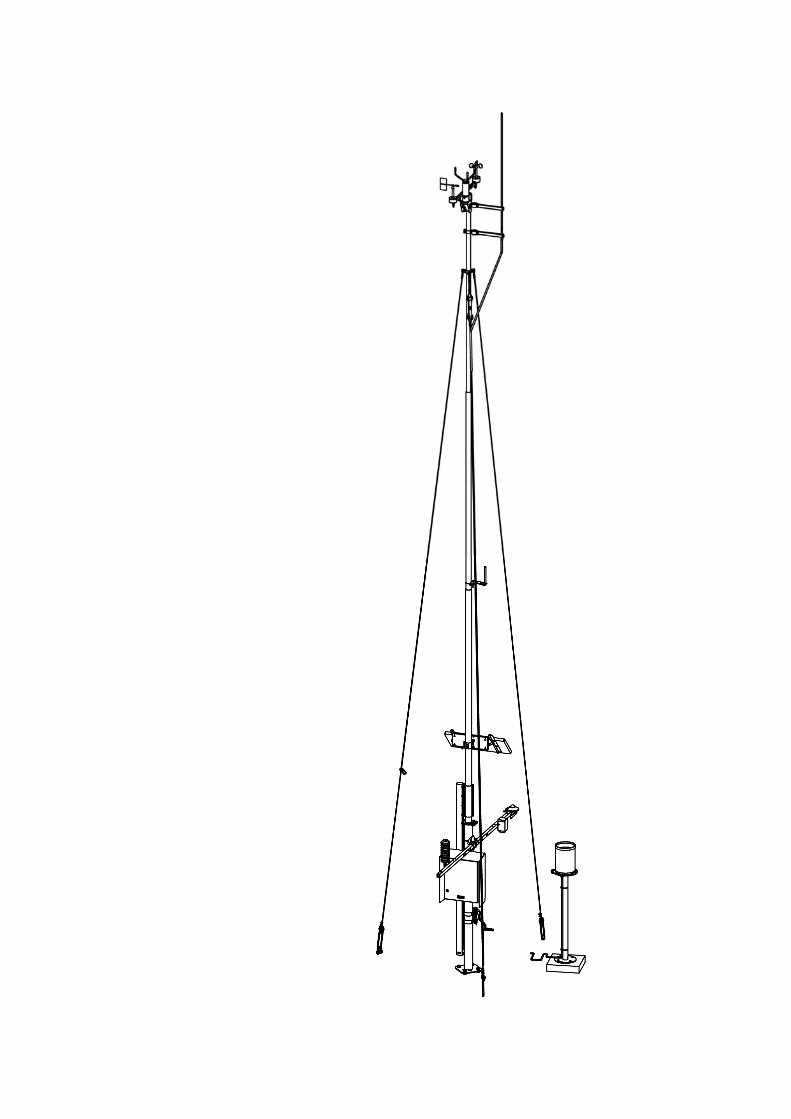
Figure 1 on page 17 presents Vaisala Automatic Weather Station AWS330.
User's Guide ______________________________________________________________________
16 __________________________________________________________________ M211296EN-A
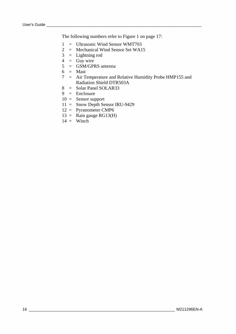
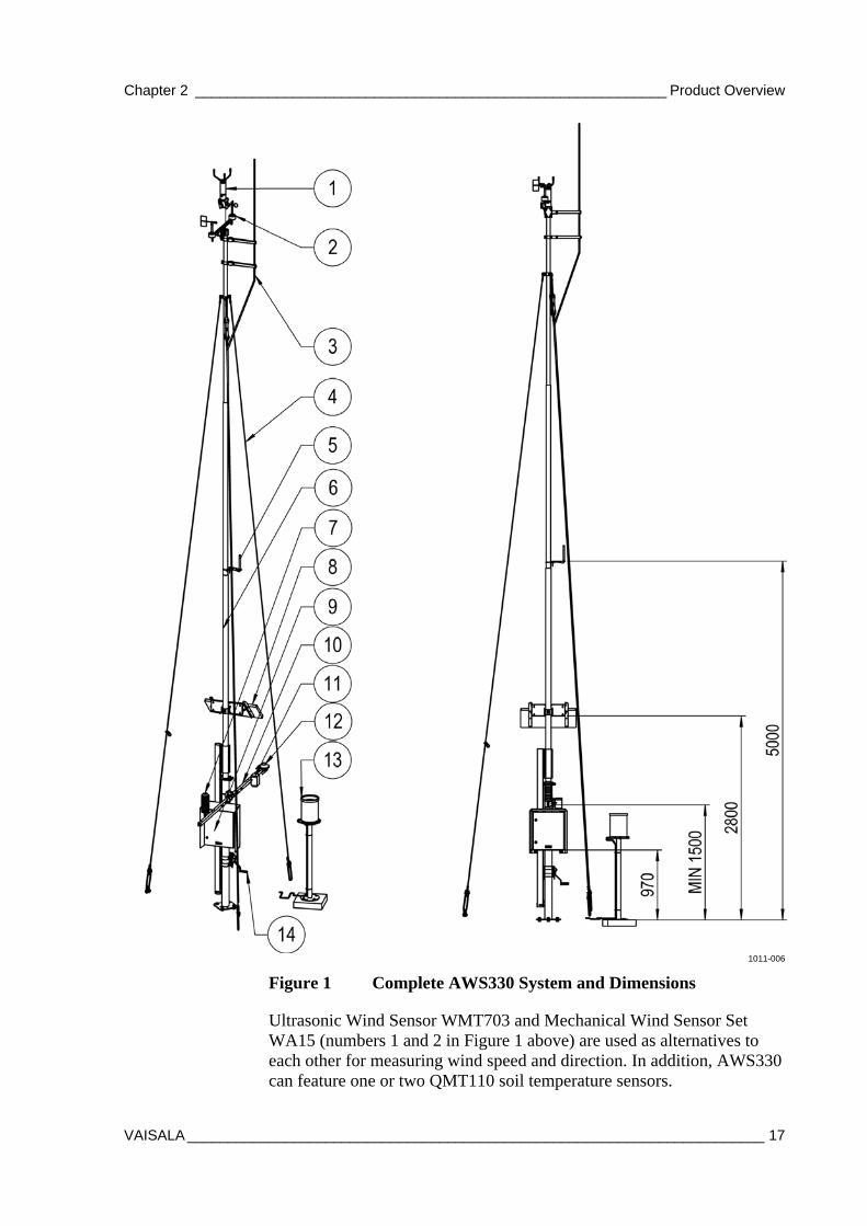
The following numbers refer to Figure 1 on page 17:
1 = Ultrasonic Wind Sensor WMT703 2 = Mechanical Wind Sensor Set WA15 3 = Lightning rod 4 = Guy wire 5 = GSM/GPRS antenna 6 = Mast 7 = Air Temperature and Relative Humidity Probe HMP155 and
Radiation Shield DTR503A 8 = Solar Panel SOLAR33 9 = Enclosure 10 = Sensor support 11 = Snow Depth Sensor IRU-9429 12 = Pyranometer CMP6 13 = Rain gauge RG13(H) 14 = Winch
Chapter 2 __________________________________________________________ Product Overview
VAISALA _______________________________________________________________________ 17
1011-006
Figure 1 Complete AWS330 System and Dimensions
Ultrasonic Wind Sensor WMT703 and Mechanical Wind Sensor Set WA15 (numbers 1 and 2 in Figure 1 above) are used as alternatives to each other for measuring wind speed and direction. In addition, AWS330 can feature one or two QMT110 soil temperature sensors.
User's Guide ______________________________________________________________________
18 __________________________________________________________________ M211296EN-A
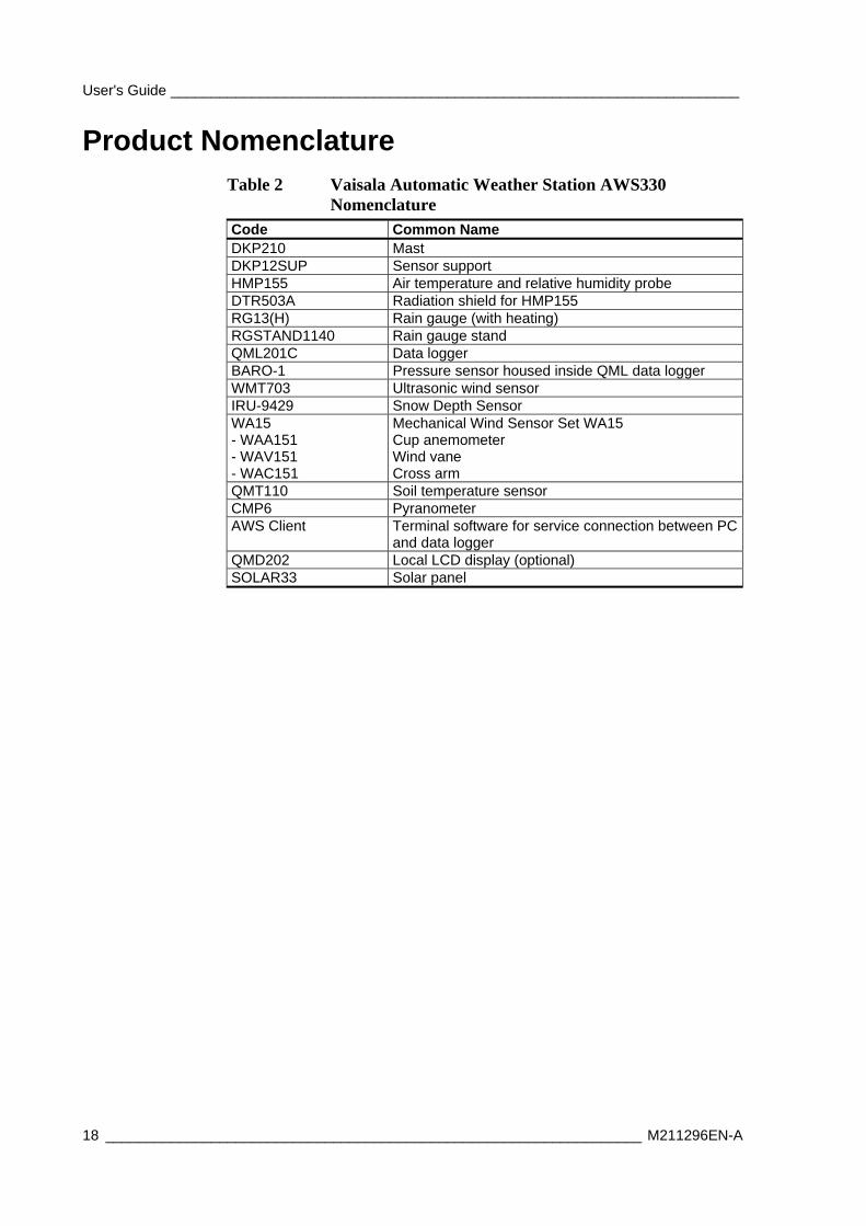
Product Nomenclature Table 2 Vaisala Automatic Weather Station AWS330
Nomenclature Code Common Name DKP210 Mast DKP12SUP Sensor support HMP155 Air temperature and relative humidity probe DTR503A Radiation shield for HMP155 RG13(H) Rain gauge (with heating) RGSTAND1140 Rain gauge stand QML201C Data logger BARO-1 Pressure sensor housed inside QML data logger WMT703 Ultrasonic wind sensor IRU-9429 Snow Depth Sensor WA15 - WAA151 - WAV151 - WAC151
Mechanical Wind Sensor Set WA15 Cup anemometer Wind vane Cross arm
QMT110 Soil temperature sensor CMP6 Pyranometer AWS Client Terminal software for service connection between PC
and data logger QMD202 Local LCD display (optional) SOLAR33 Solar panel
Chapter 3 ______________________________________________________ Functional Description
VAISALA _______________________________________________________________________ 19
CHAPTER 3
FUNCTIONAL DESCRIPTION
This section describes the operating principles of AWS330.
Operating Principles Sensors are measured by AWS330 system as:
- Voltage or resistance input converted to measurement value by analog to digital conversion. For example, Pt100 temperature.
- Discrete pulse input converted to measurement value by counter. For example, Rain Gauge RG13(H).
- Frequency converted to measurement value by frequency (counter/time) measurement. For example, Anemometer WAA15 (wind speed).
- Intelligent sensors providing observation values as messages through serial link. For example, WMT703 wind measurement.
Measurements are quality-checked against set limits to produce observation values.
Observation values are processed further to produce statistical and derived values.
Statistical and derived values are used to compose observation and alarms messages.
Messages are passed through communication devices to Observation Display or data collection system.
User's Guide ______________________________________________________________________
20 __________________________________________________________________ M211296EN-A
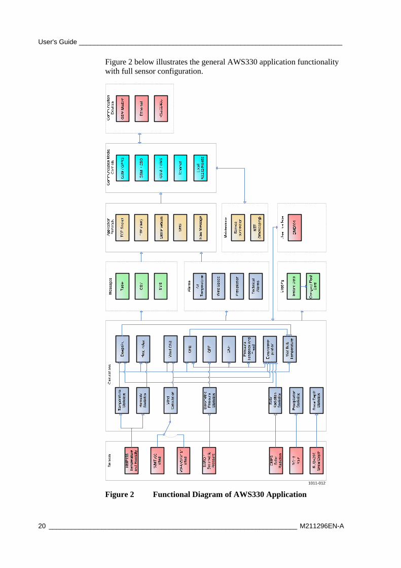
Figure 2 below illustrates the general AWS330 application functionality with full sensor configuration.
1011-012
Figure 2 Functional Diagram of AWS330 Application
Chapter 3 ______________________________________________________ Functional Description
VAISALA _______________________________________________________________________ 21
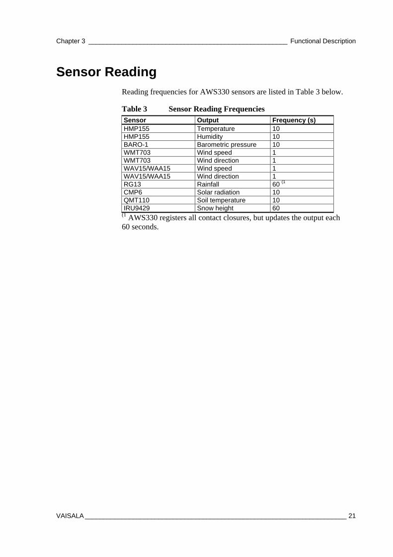
Sensor Reading Reading frequencies for AWS330 sensors are listed in Table 3 below.
Table 3 Sensor Reading Frequencies Sensor Output Frequency (s) HMP155 Temperature 10 HMP155 Humidity 10 BARO-1 Barometric pressure 10 WMT703 Wind speed 1 WMT703 Wind direction 1 WAV15/WAA15 Wind speed 1 WAV15/WAA15 Wind direction 1 RG13 Rainfall 60 (1 CMP6 Solar radiation 10 QMT110 Soil temperature 10 IRU9429 Snow height 60
(1 AWS330 registers all contact closures, but updates the output each 60 seconds.
User's Guide ______________________________________________________________________
22 __________________________________________________________________ M211296EN-A
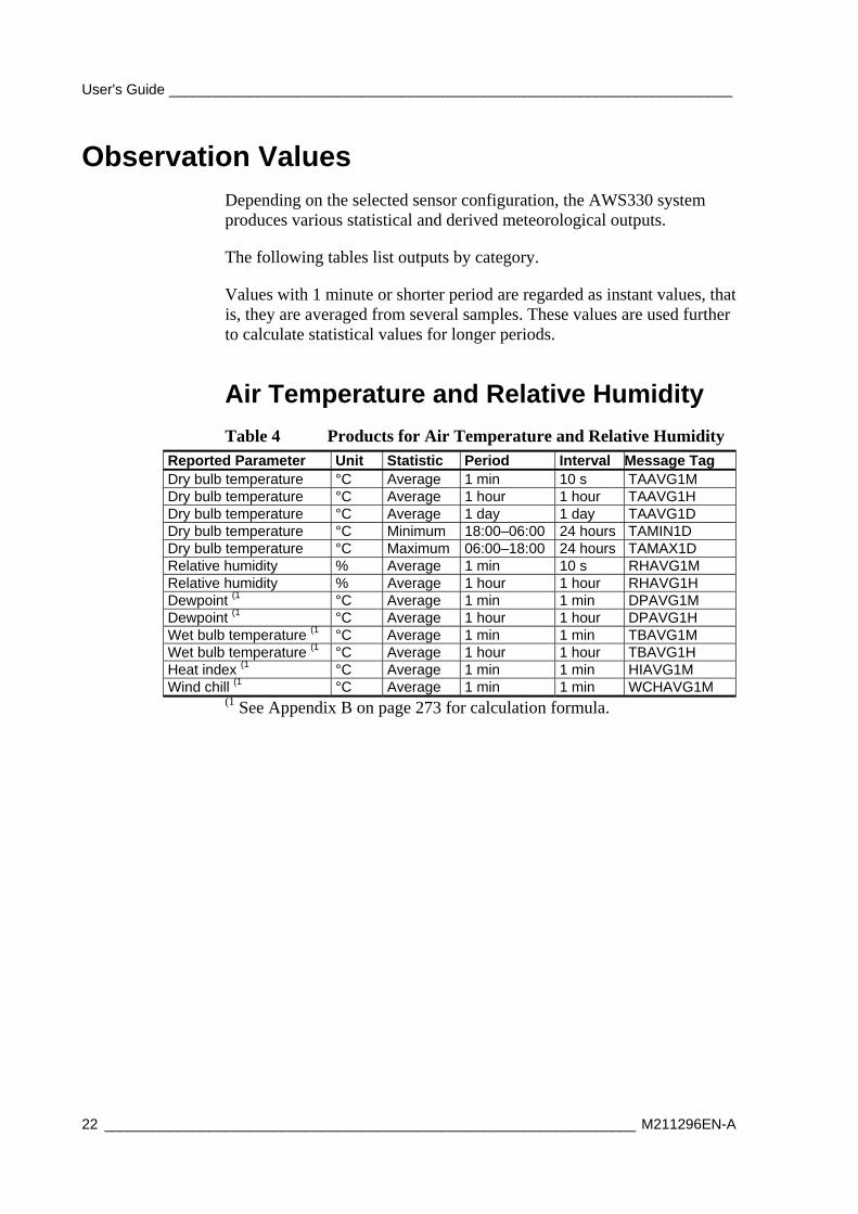
Observation Values Depending on the selected sensor configuration, the AWS330 system produces various statistical and derived meteorological outputs.
The following tables list outputs by category.
Values with 1 minute or shorter period are regarded as instant values, that is, they are averaged from several samples. These values are used further to calculate statistical values for longer periods.
Air Temperature and Relative Humidity
Table 4 Products for Air Temperature and Relative Humidity Reported Parameter Unit Statistic Period Interval Message Tag Dry bulb temperature °C Average 1 min 10 s TAAVG1M Dry bulb temperature °C Average 1 hour 1 hour TAAVG1H Dry bulb temperature °C Average 1 day 1 day TAAVG1D Dry bulb temperature °C Minimum 18:00–06:00 24 hours TAMIN1D Dry bulb temperature °C Maximum 06:00–18:00 24 hours TAMAX1D Relative humidity % Average 1 min 10 s RHAVG1M Relative humidity % Average 1 hour 1 hour RHAVG1H Dewpoint (1 °C Average 1 min 1 min DPAVG1M Dewpoint (1 °C Average 1 hour 1 hour DPAVG1H Wet bulb temperature (1 °C Average 1 min 1 min TBAVG1M Wet bulb temperature (1 °C Average 1 hour 1 hour TBAVG1H Heat index (1 °C Average 1 min 1 min HIAVG1M Wind chill (1 °C Average 1 min 1 min WCHAVG1M
(1 See Appendix B on page 273 for calculation formula.
Chapter 3 ______________________________________________________ Functional Description
VAISALA _______________________________________________________________________ 23
Atmospheric Pressure/Vapor Pressure
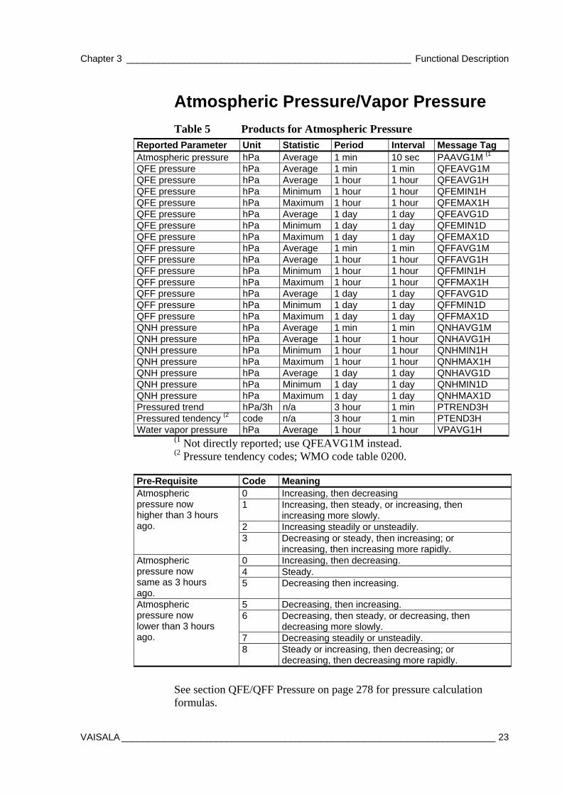
Table 5 Products for Atmospheric Pressure Reported Parameter Unit Statistic Period Interval Message Tag Atmospheric pressure hPa Average 1 min 10 sec PAAVG1M (1 QFE pressure hPa Average 1 min 1 min QFEAVG1M QFE pressure hPa Average 1 hour 1 hour QFEAVG1H QFE pressure hPa Minimum 1 hour 1 hour QFEMIN1H QFE pressure hPa Maximum 1 hour 1 hour QFEMAX1H QFE pressure hPa Average 1 day 1 day QFEAVG1D QFE pressure hPa Minimum 1 day 1 day QFEMIN1D QFE pressure hPa Maximum 1 day 1 day QFEMAX1D QFF pressure hPa Average 1 min 1 min QFFAVG1M QFF pressure hPa Average 1 hour 1 hour QFFAVG1H QFF pressure hPa Minimum 1 hour 1 hour QFFMIN1H QFF pressure hPa Maximum 1 hour 1 hour QFFMAX1H QFF pressure hPa Average 1 day 1 day QFFAVG1D QFF pressure hPa Minimum 1 day 1 day QFFMIN1D QFF pressure hPa Maximum 1 day 1 day QFFMAX1D QNH pressure hPa Average 1 min 1 min QNHAVG1M QNH pressure hPa Average 1 hour 1 hour QNHAVG1H QNH pressure hPa Minimum 1 hour 1 hour QNHMIN1H QNH pressure hPa Maximum 1 hour 1 hour QNHMAX1H QNH pressure hPa Average 1 day 1 day QNHAVG1D QNH pressure hPa Minimum 1 day 1 day QNHMIN1D QNH pressure hPa Maximum 1 day 1 day QNHMAX1D Pressured trend hPa/3h n/a 3 hour 1 min PTREND3H Pressured tendency (2 code n/a 3 hour 1 min PTEND3H Water vapor pressure hPa Average 1 hour 1 hour VPAVG1H
(1 Not directly reported; use QFEAVG1M instead. (2 Pressure tendency codes; WMO code table 0200.
Pre-Requisite Code Meaning 0 Increasing, then decreasing 1 Increasing, then steady, or increasing, then
increasing more slowly. 2 Increasing steadily or unsteadily.
Atmospheric pressure now higher than 3 hours ago.
3 Decreasing or steady, then increasing; or increasing, then increasing more rapidly.
0 Increasing, then decreasing. 4 Steady.
Atmospheric pressure now same as 3 hours ago.
5 Decreasing then increasing.
5 Decreasing, then increasing. 6 Decreasing, then steady, or decreasing, then
decreasing more slowly. 7 Decreasing steadily or unsteadily.
Atmospheric pressure now lower than 3 hours ago.
8 Steady or increasing, then decreasing; or decreasing, then decreasing more rapidly.
See section QFE/QFF Pressure on page 278 for pressure calculation formulas.
User's Guide ______________________________________________________________________
24 __________________________________________________________________ M211296EN-A
Wind
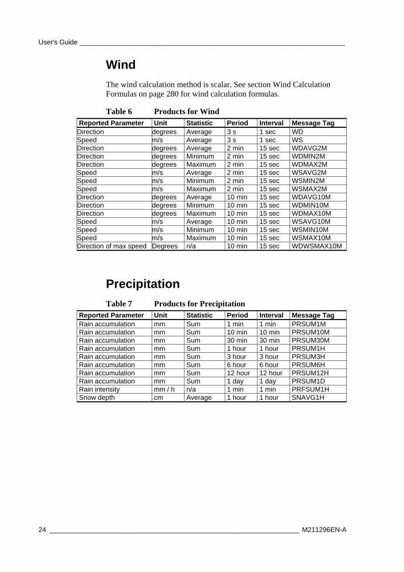
The wind calculation method is scalar. See section Wind Calculation Formulas on page 280 for wind calculation formulas.
Table 6 Products for Wind Reported Parameter Unit Statistic Period Interval Message Tag
Direction degrees Average 3 s 1 sec WD Speed m/s Average 3 s 1 sec WS Direction degrees Average 2 min 15 sec WDAVG2M Direction degrees Minimum 2 min 15 sec WDMIN2M Direction degrees Maximum 2 min 15 sec WDMAX2M Speed m/s Average 2 min 15 sec WSAVG2M Speed m/s Minimum 2 min 15 sec WSMIN2M Speed m/s Maximum 2 min 15 sec WSMAX2M Direction degrees Average 10 min 15 sec WDAVG10M Direction degrees Minimum 10 min 15 sec WDMIN10M Direction degrees Maximum 10 min 15 sec WDMAX10M Speed m/s Average 10 min 15 sec WSAVG10M Speed m/s Minimum 10 min 15 sec WSMIN10M Speed m/s Maximum 10 min 15 sec WSMAX10M Direction of max speed Degrees n/a 10 min 15 sec WDWSMAX10M
Precipitation
Table 7 Products for Precipitation Reported Parameter Unit Statistic Period Interval Message Tag Rain accumulation mm Sum 1 min 1 min PRSUM1M Rain accumulation mm Sum 10 min 10 min PRSUM10M Rain accumulation mm Sum 30 min 30 min PRSUM30M Rain accumulation mm Sum 1 hour 1 hour PRSUM1H Rain accumulation mm Sum 3 hour 3 hour PRSUM3H Rain accumulation mm Sum 6 hour 6 hour PRSUM6H Rain accumulation mm Sum 12 hour 12 hour PRSUM12H Rain accumulation mm Sum 1 day 1 day PRSUM1D Rain intensity mm / h n/a 1 min 1 min PRFSUM1H Snow depth cm Average 1 hour 1 hour SNAVG1H
Chapter 3 ______________________________________________________ Functional Description
VAISALA _______________________________________________________________________ 25
Soil/Water Temperature
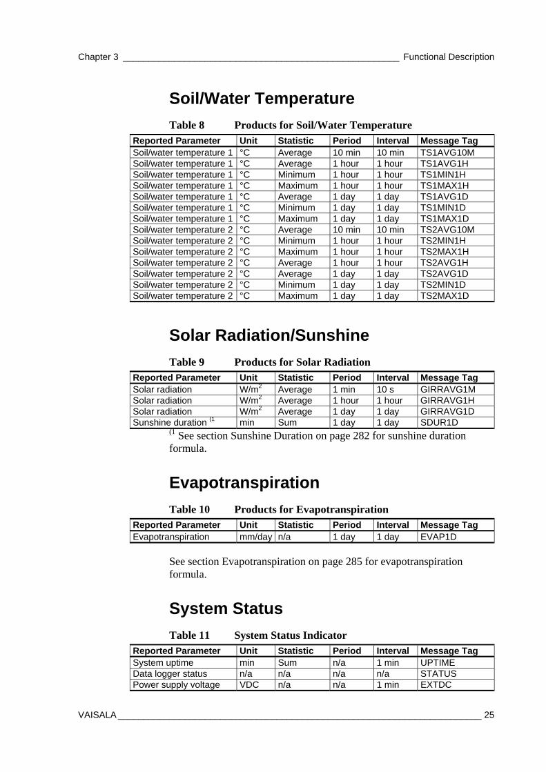
Table 8 Products for Soil/Water Temperature Reported Parameter Unit Statistic Period Interval Message Tag Soil/water temperature 1 °C Average 10 min 10 min TS1AVG10M Soil/water temperature 1 °C Average 1 hour 1 hour TS1AVG1H Soil/water temperature 1 °C Minimum 1 hour 1 hour TS1MIN1H Soil/water temperature 1 °C Maximum 1 hour 1 hour TS1MAX1H Soil/water temperature 1 °C Average 1 day 1 day TS1AVG1D Soil/water temperature 1 °C Minimum 1 day 1 day TS1MIN1D Soil/water temperature 1 °C Maximum 1 day 1 day TS1MAX1D Soil/water temperature 2 °C Average 10 min 10 min TS2AVG10M Soil/water temperature 2 °C Minimum 1 hour 1 hour TS2MIN1H Soil/water temperature 2 °C Maximum 1 hour 1 hour TS2MAX1H Soil/water temperature 2 °C Average 1 hour 1 hour TS2AVG1H Soil/water temperature 2 °C Average 1 day 1 day TS2AVG1D Soil/water temperature 2 °C Minimum 1 day 1 day TS2MIN1D Soil/water temperature 2 °C Maximum 1 day 1 day TS2MAX1D
Solar Radiation/Sunshine
Table 9 Products for Solar Radiation Reported Parameter Unit Statistic Period Interval Message Tag Solar radiation W/m2 Average 1 min 10 s GIRRAVG1M Solar radiation W/m2 Average 1 hour 1 hour GIRRAVG1H Solar radiation W/m2 Average 1 day 1 day GIRRAVG1D Sunshine duration (1 min Sum 1 day 1 day SDUR1D
(1 See section Sunshine Duration on page 282 for sunshine duration formula.
Evapotranspiration
Table 10 Products for Evapotranspiration Reported Parameter Unit Statistic Period Interval Message Tag Evapotranspiration mm/day n/a 1 day 1 day EVAP1D
See section Evapotranspiration on page 285 for evapotranspiration formula.
System Status
Table 11 System Status Indicator Reported Parameter Unit Statistic Period Interval Message Tag System uptime min Sum n/a 1 min UPTIME Data logger status n/a n/a n/a n/a STATUS Power supply voltage VDC n/a n/a 1 min EXTDC
User's Guide ______________________________________________________________________
26 __________________________________________________________________ M211296EN-A
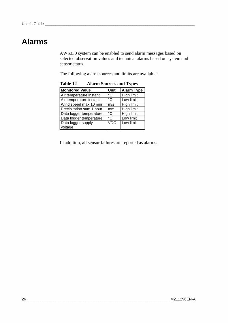
Alarms AWS330 system can be enabled to send alarm messages based on selected observation values and technical alarms based on system and sensor status.
The following alarm sources and limits are available:
Table 12 Alarm Sources and Types Monitored Value Unit Alarm TypeAir temperature instant °C High limit Air temperature instant °C Low limit Wind speed max 10 min m/s High limit Precipitation sum 1 hour mm High limit Data logger temperature °C High limit Data logger temperature °C Low limit Data logger supply voltage
VDC Low limit
In addition, all sensor failures are reported as alarms.
Chapter 3 ______________________________________________________ Functional Description
VAISALA _______________________________________________________________________ 27
Message Formats
Observation Messages
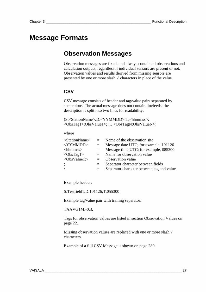
Observation messages are fixed, and always contain all observations and calculation outputs, regardless if individual sensors are present or not. Observation values and results derived from missing sensors are presented by one or more slash '/' characters in place of the value.
CSV
CSV message consists of header and tag/value pairs separated by semicolons. The actual message does not contain linefeeds; the description is split into two lines for readability.
(S:<StationName>;D:<YYMMDD>;T:<hhmmss>; <ObsTag1>:ObsValue1>; … <ObsTagN:ObsValueN>)
where
<StationName> = Name of the observation site <YYMMDD> = Message date UTC; for example, 101126 <hhmmss> = Message time UTC; for example, 085300 <ObsTag1> = Name for observation value <ObsValue1:> = Observation value ; = Separator character between fields : = Separator character between tag and value
Example header:
S:Testfield1;D:101126;T:055300
Example tag/value pair with trailing separator:
TAAVG1M:-0.3;
Tags for observation values are listed in section Observation Values on page 22.
Missing observation values are replaced with one or more slash '/' characters.
Example of a full CSV Message is shown on page 289.
User's Guide ______________________________________________________________________
28 __________________________________________________________________ M211296EN-A
Table
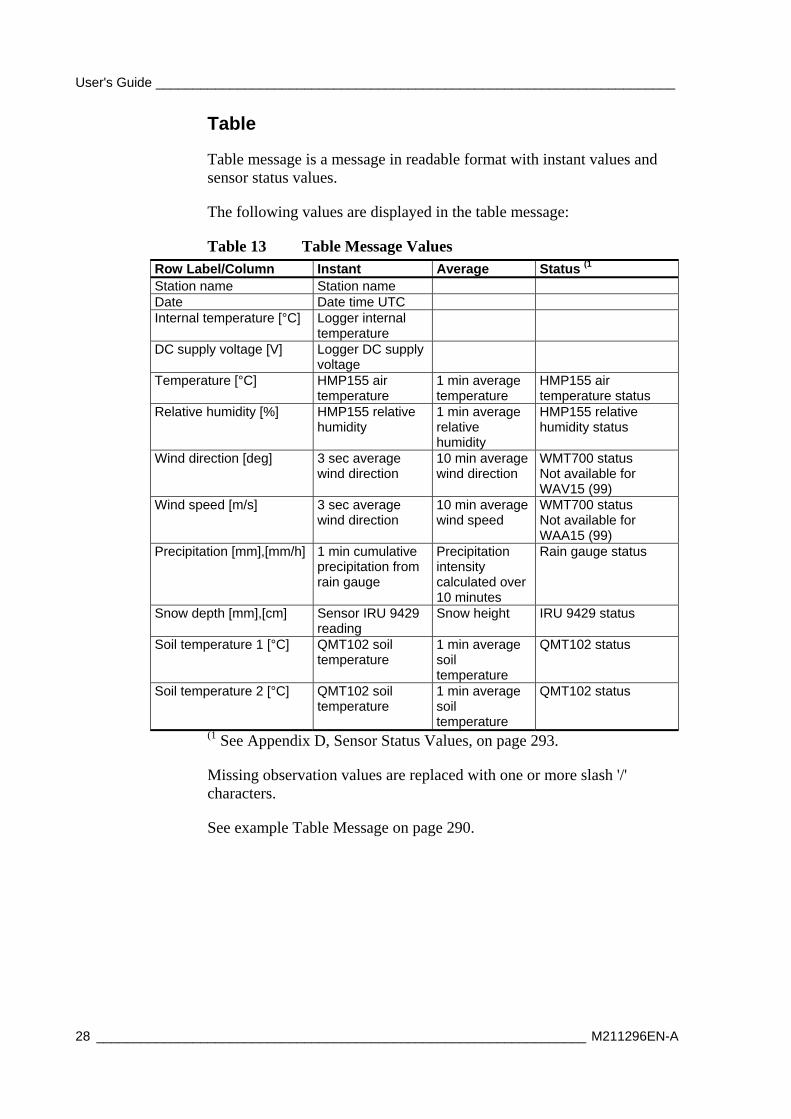
Table message is a message in readable format with instant values and sensor status values.
The following values are displayed in the table message:
Table 13 Table Message Values Row Label/Column Instant Average Status (1 Station name Station name Date Date time UTC Internal temperature [°C] Logger internal
temperature
DC supply voltage [V] Logger DC supply voltage
Temperature [°C] HMP155 air temperature
1 min average temperature
HMP155 air temperature status
Relative humidity [%] HMP155 relative humidity
1 min average relative humidity
HMP155 relative humidity status
Wind direction [deg] 3 sec average wind direction
10 min average wind direction
WMT700 status Not available for WAV15 (99)
Wind speed [m/s] 3 sec average wind direction
10 min average wind speed
WMT700 status Not available for WAA15 (99)
Precipitation [mm],[mm/h] 1 min cumulative precipitation from rain gauge
Precipitation intensity calculated over 10 minutes
Rain gauge status
Snow depth [mm],[cm] Sensor IRU 9429 reading
Snow height IRU 9429 status
Soil temperature 1 [°C] QMT102 soil temperature
1 min average soil temperature
QMT102 status
Soil temperature 2 [°C] QMT102 soil temperature
1 min average soil temperature
QMT102 status
(1 See Appendix D, Sensor Status Values, on page 293.
Missing observation values are replaced with one or more slash '/' characters.
See example Table Message on page 290.
Chapter 3 ______________________________________________________ Functional Description
VAISALA _______________________________________________________________________ 29
SMS
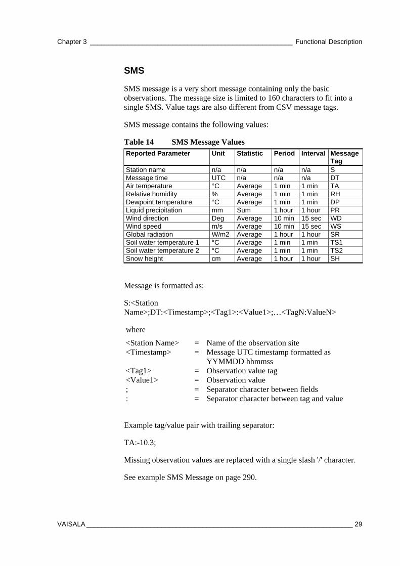
SMS message is a very short message containing only the basic observations. The message size is limited to 160 characters to fit into a single SMS. Value tags are also different from CSV message tags.
SMS message contains the following values:
Table 14 SMS Message Values Reported Parameter Unit Statistic Period Interval Message
Tag Station name n/a n/a n/a n/a S Message time UTC n/a n/a n/a DT Air temperature °C Average 1 min 1 min TA Relative humidity % Average 1 min 1 min RH Dewpoint temperature °C Average 1 min 1 min DP Liquid precipitation mm Sum 1 hour 1 hour PR Wind direction Deg Average 10 min 15 sec WD Wind speed m/s Average 10 min 15 sec WS Global radiation W/m2 Average 1 hour 1 hour SR Soil water temperature 1 °C Average 1 min 1 min TS1 Soil water temperature 2 °C Average 1 min 1 min TS2 Snow height cm Average 1 hour 1 hour SH
Message is formatted as:
S:<Station Name>;DT:<Timestamp>;<Tag1>:<Value1>;…<TagN:ValueN>
where
<Station Name> = Name of the observation site <Timestamp> = Message UTC timestamp formatted as
YYMMDD hhmmss <Tag1> = Observation value tag <Value1> = Observation value ; = Separator character between fields : = Separator character between tag and value
Example tag/value pair with trailing separator:
TA:-10.3;
Missing observation values are replaced with a single slash '/' character.
See example SMS Message on page 290.
User's Guide ______________________________________________________________________
30 __________________________________________________________________ M211296EN-A
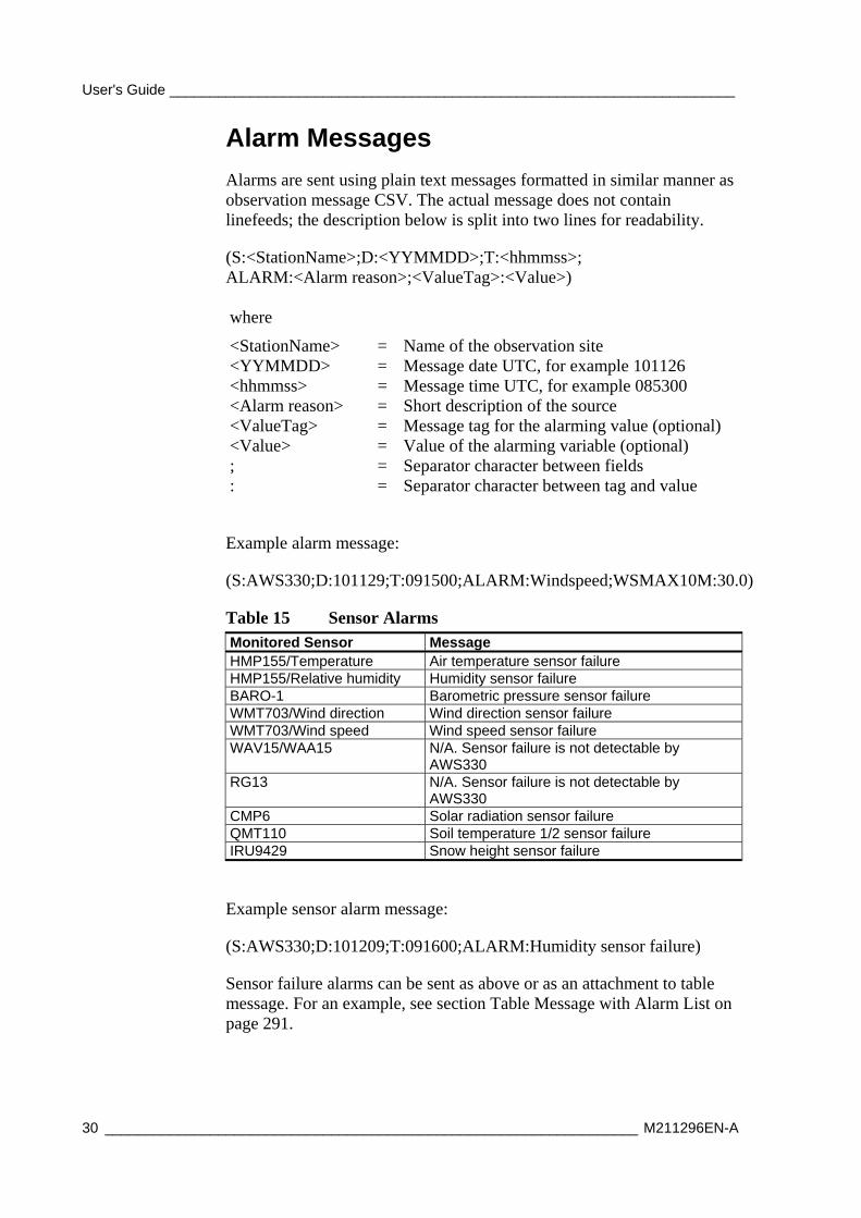
Alarm Messages
Alarms are sent using plain text messages formatted in similar manner as observation message CSV. The actual message does not contain linefeeds; the description below is split into two lines for readability.
(S:<StationName>;D:<YYMMDD>;T:<hhmmss>; ALARM:<Alarm reason>;<ValueTag>:<Value>) where
<StationName> = Name of the observation site <YYMMDD> = Message date UTC, for example 101126 <hhmmss> = Message time UTC, for example 085300 <Alarm reason> = Short description of the source <ValueTag> = Message tag for the alarming value (optional) <Value> = Value of the alarming variable (optional) ; = Separator character between fields : = Separator character between tag and value
Example alarm message:
(S:AWS330;D:101129;T:091500;ALARM:Windspeed;WSMAX10M:30.0)
Table 15 Sensor Alarms Monitored Sensor Message HMP155/Temperature Air temperature sensor failure HMP155/Relative humidity Humidity sensor failure BARO-1 Barometric pressure sensor failure WMT703/Wind direction Wind direction sensor failure WMT703/Wind speed Wind speed sensor failure WAV15/WAA15 N/A. Sensor failure is not detectable by
AWS330 RG13 N/A. Sensor failure is not detectable by
AWS330 CMP6 Solar radiation sensor failure QMT110 Soil temperature 1/2 sensor failure IRU9429 Snow height sensor failure
Example sensor alarm message:
(S:AWS330;D:101209;T:091600;ALARM:Humidity sensor failure)
Sensor failure alarms can be sent as above or as an attachment to table message. For an example, see section Table Message with Alarm List on page 291.
Chapter 4 _______________________________________________________________ Installation
VAISALA _______________________________________________________________________ 31
CHAPTER 4
INSTALLATION
This chapter provides you with information that is intended to help you install AWS330.
NOTE The individual sensors may come with their own instructions. However, refer to this manual for all installation instructions.
NOTE The delivery includes accessories, such as nuts and bolts, that can be used in other installations than mast installation. Not all have to be used.
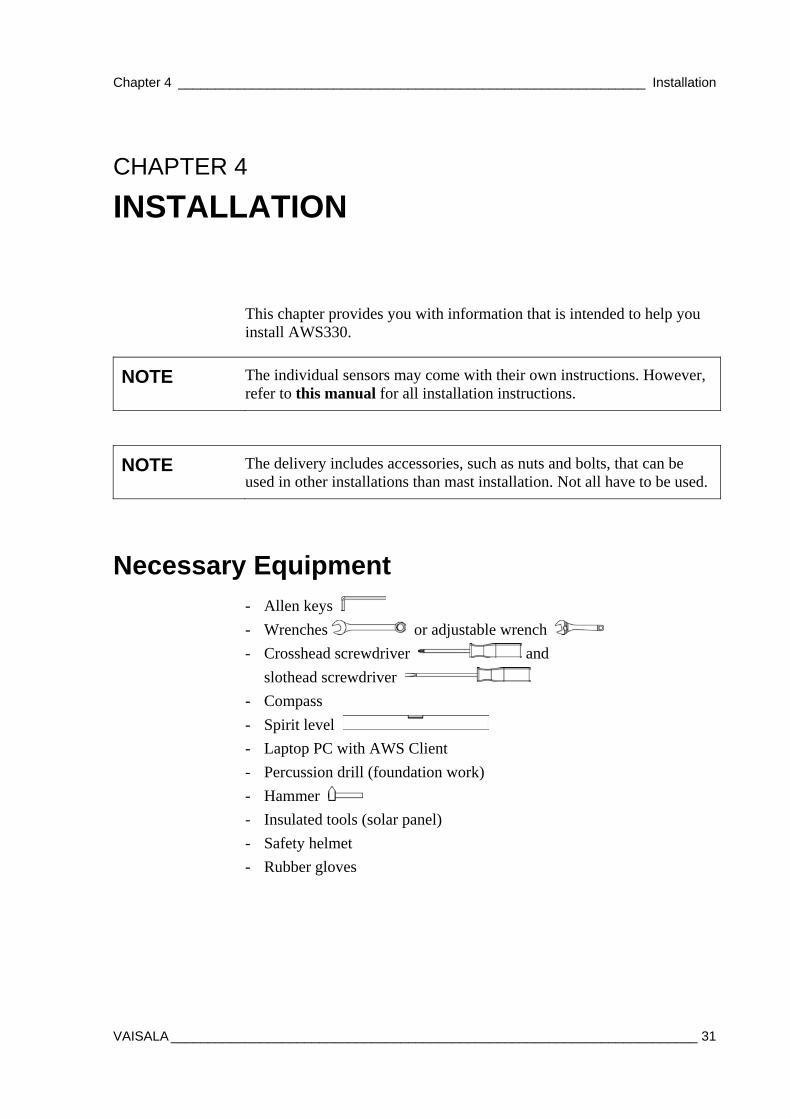
Necessary Equipment - Allen keys
- Wrenches or adjustable wrench
- Crosshead screwdriver and
slothead screwdriver
- Compass
- Spirit level
- Laptop PC with AWS Client
- Percussion drill (foundation work)
- Hammer
- Insulated tools (solar panel)
- Safety helmet
- Rubber gloves
User's Guide ______________________________________________________________________
32 __________________________________________________________________ M211296EN-A
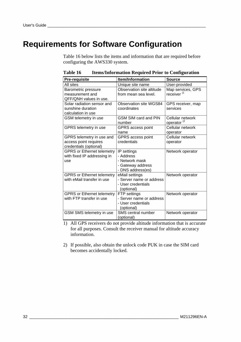
Requirements for Software Configuration Table 16 below lists the items and information that are required before configuring the AWS330 system.
Table 16 Items/Information Required Prior to Configuration Pre-requisite Item/Information Source All sites Unique site name User-provided Barometric pressure measurement and QFF/QNH values in use.
Observation site altitude from mean sea level.
Map services, GPS receiver (1
Solar radiation sensor and sunshine duration calculation in use
Observation site WGS84 coordinates
GPS receiver, map services
GSM telemetry in use GSM SIM card and PIN number
Cellular network operator (2
GPRS telemetry in use GPRS access point name
Cellular network operator
GPRS telemetry in use and access point requires credentials (optional)
GPRS access point credentials
Cellular network operator
GPRS or Ethernet telemetry with fixed IP addressing in use
IP settings - Address - Network mask - Gateway address - DNS address(es)
Network operator
GPRS or Ethernet telemetry with eMail transfer in use
eMail settings - Server name or address- User credentials (optional)
Network operator
GPRS or Ethernet telemetry with FTP transfer in use
FTP settings - Server name or address- User credentials (optional)
Network operator
GSM SMS telemetry in use SMS central number (optional)
Network operator
1) All GPS receivers do not provide altitude information that is accurate for all purposes. Consult the receiver manual for altitude accuracy information.
2) If possible, also obtain the unlock code PUK in case the SIM card becomes accidentally locked.
Chapter 4 _______________________________________________________________ Installation
VAISALA _______________________________________________________________________ 33
Selecting Location
Ambient Measurements
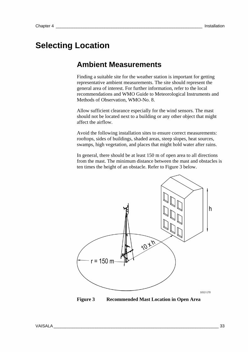
Finding a suitable site for the weather station is important for getting representative ambient measurements. The site should represent the general area of interest. For further information, refer to the local recommendations and WMO Guide to Meteorological Instruments and Methods of Observation, WMO-No. 8.
Allow sufficient clearance especially for the wind sensors. The mast should not be located next to a building or any other object that might affect the airflow.
Avoid the following installation sites to ensure correct measurements: rooftops, sides of buildings, shaded areas, steep slopes, heat sources, swamps, high vegetation, and places that might hold water after rains.
In general, there should be at least 150 m of open area to all directions from the mast. The minimum distance between the mast and obstacles is ten times the height of an obstacle. Refer to Figure 3 below.
1012-170
Figure 3 Recommended Mast Location in Open Area
User's Guide ______________________________________________________________________
34 __________________________________________________________________ M211296EN-A
Tilt Direction of the Mast
Also note the tilting direction of the mast. When installed in the northern hemisphere, the mast tilts to the west. There should be a clear area up to 9 m on the west side of the mast. The area should be free of obstacles preventing the mast from being erected and tilted.
Soil Evaluation for the Mast
Always evaluate the soil to determine the appropriate type of the foundation required. When designing the foundation, the local construction companies must be consulted to find out about the soil and frost conditions in your area. When the soil is frost-susceptible, make sure to always use proper insulation.
CAUTION For the mast base installation, the soil bearing capacity has to exceed 45 kPa (940 pounds-force/sq. foot).
Chapter 4 _______________________________________________________________ Installation
VAISALA _______________________________________________________________________ 35
Site Preparation
Power Supply and Communication Lines
Before assembling the mast, the power supply and communication lines must be available. The primary AC power service must comply with the National Electrical Code (NEC) or equivalent specifications for grounding the primary power service entrance. The AC (mains) power must be continuous, 110–230 V/50 Hz, and without spikes and blackouts. If the AC (mains) voltage is fluctuating more than the given tolerance allows, the AC (mains) voltage stabilizers are recommended.
WARNING All electrical installations must be carried by licensed experts as governed by local and state authorities, legislation, and regulations.
The following applies to all field cabling:
- Use armored field cables.
- Cables must be suitable for underground use.
- Check the cable core diameter according to maximum allowable drop.
- Route the cables through conduits to the equipment.
- Check cable conduit diameters or use additional termination boxes.
- Ground the cable shield at both ends.
- Use spike and overvoltage protection devices at both ends of field cables.
Always make a detailed cabling and wiring plan. Data transmission lines from the outdoor sites to indoor devices have to be prepared carefully. Also the power supply for the equipment used needs to be planned carefully.
It is recommended that you use a conduit to protect the cables that connect the indoor components to the outdoor components from damage and moisture. Also traffic, standing water, and the twist and stress caused by the connectors will damage the cables.
User's Guide ______________________________________________________________________
36 __________________________________________________________________ M211296EN-A
Equipment Grounding and Lightning Protection
WARNING Consult the local electricity professionals for the local grounding requirements. The customer is responsible for supplying grounding cables, rods, clamps, power cables, long distance signal cables, and conduits for cables.
With mast installations, equipment grounding and lightning protection must be done separately. The main principles are as follows:
- Proper equipment grounding is required for personnel safety and for equipment protection. A piece of equipment is grounded by connecting its metal structures and electrical equipment to an external buried ground rod. Individual site requirements may dictate changes in the procedures described in this manual. Changes are permissible as long as protection equivalent to the original requirements is provided for the system.
WARNING Failure to provide proper grounding may result in personnel injury or death from electrical shock and may severely damage the equipment.
WARNING Lightning protection is required to prevent personnel injury and equipment damage due to direct lightning strikes and lightning-induced current surges.
- The materials used in the manufacture of the grounding systems must be chosen to prevent them from forming an electrolytic couple. It is recommended that you use copper (Cu).
Chapter 4 _______________________________________________________________ Installation
VAISALA _______________________________________________________________________ 37
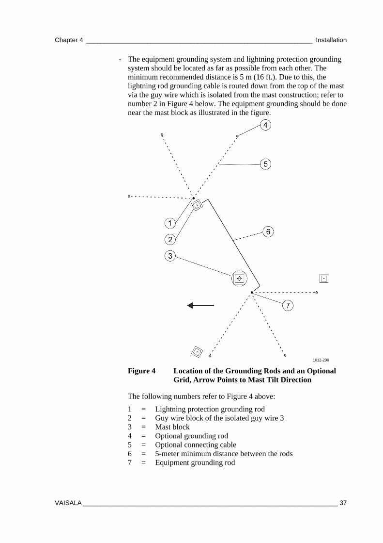
- The equipment grounding system and lightning protection grounding system should be located as far as possible from each other. The minimum recommended distance is 5 m (16 ft.). Due to this, the lightning rod grounding cable is routed down from the top of the mast via the guy wire which is isolated from the mast construction; refer to number 2 in Figure 4 below. The equipment grounding should be done near the mast block as illustrated in the figure.
1012-200
Figure 4 Location of the Grounding Rods and an Optional Grid, Arrow Points to Mast Tilt Direction
The following numbers refer to Figure 4 above:
1 = Lightning protection grounding rod 2 = Guy wire block of the isolated guy wire 3 3 = Mast block 4 = Optional grounding rod 5 = Optional connecting cable 6 = 5-meter minimum distance between the rods 7 = Equipment grounding rod
User's Guide ______________________________________________________________________
38 __________________________________________________________________ M211296EN-A
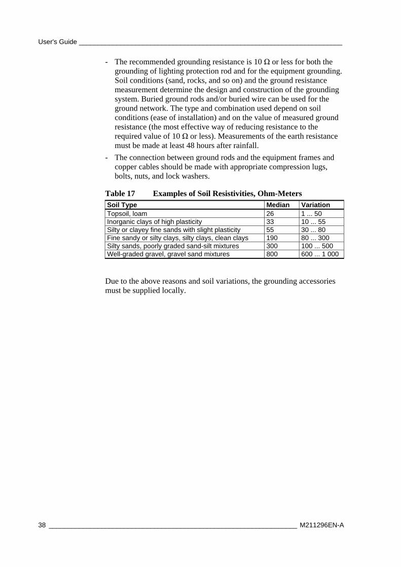
- The recommended grounding resistance is 10 Ω or less for both the grounding of lighting protection rod and for the equipment grounding. Soil conditions (sand, rocks, and so on) and the ground resistance measurement determine the design and construction of the grounding system. Buried ground rods and/or buried wire can be used for the ground network. The type and combination used depend on soil conditions (ease of installation) and on the value of measured ground resistance (the most effective way of reducing resistance to the required value of 10 Ω or less). Measurements of the earth resistance must be made at least 48 hours after rainfall.
- The connection between ground rods and the equipment frames and copper cables should be made with appropriate compression lugs, bolts, nuts, and lock washers.
Table 17 Examples of Soil Resistivities, Ohm-Meters Soil Type Median Variation Topsoil, loam 26 1 ... 50 Inorganic clays of high plasticity 33 10 ... 55 Silty or clayey fine sands with slight plasticity 55 30 ... 80 Fine sandy or silty clays, silty clays, clean clays 190 80 ... 300 Silty sands, poorly graded sand-silt mixtures 300 100 ... 500 Well-graded gravel, gravel sand mixtures 800 600 ... 1 000
Due to the above reasons and soil variations, the grounding accessories must be supplied locally.
Chapter 4 _______________________________________________________________ Installation
VAISALA _______________________________________________________________________ 39
Foundation
Soil and Frost Conditions
When designing the foundation, the local construction companies must be consulted to find out about the soil and frost conditions in your area. When the soil is frost-susceptible, make sure that you always use proper insulation.
Orientation of the Mast
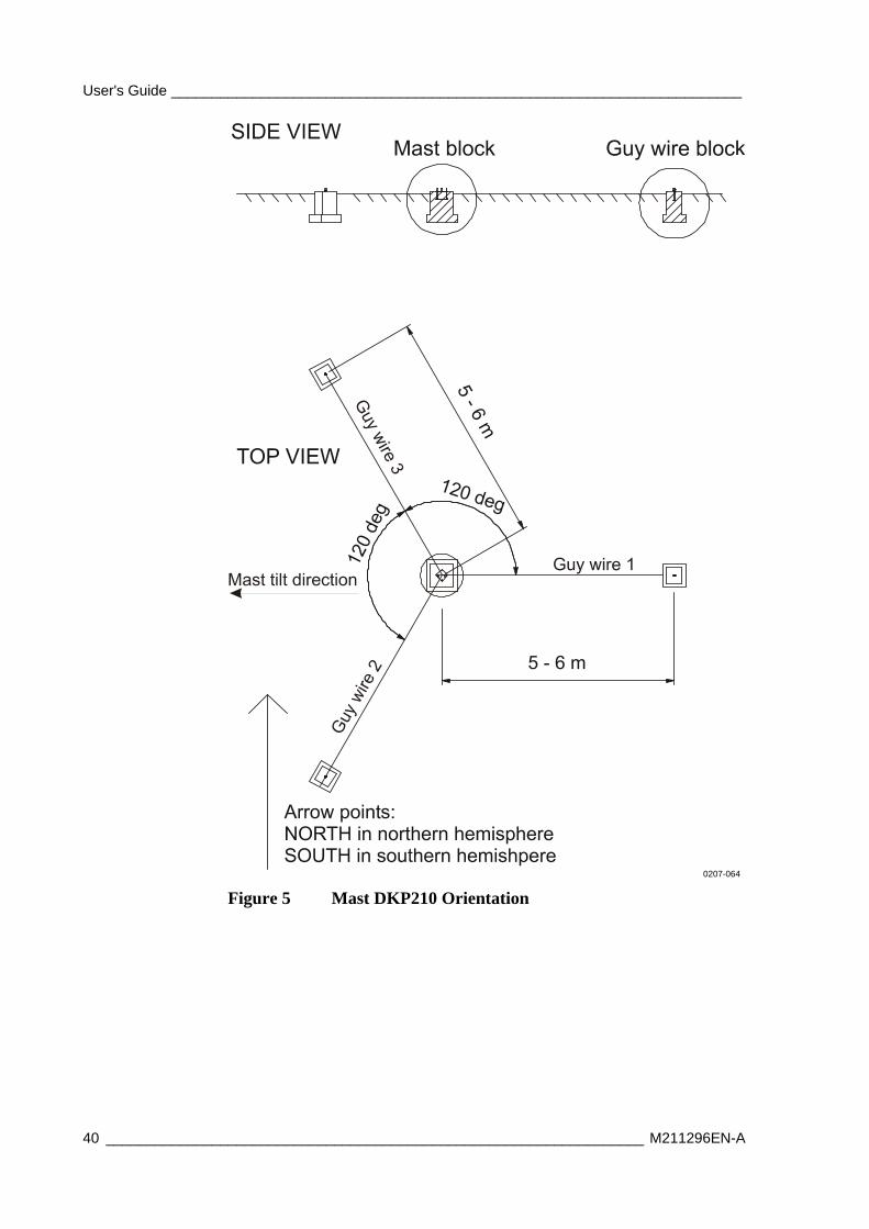
Refer to Figure 5 on page 40 for the orientation of the mast. The concrete blocks for guy wires have to be placed so that the pole mast can be tilted west (east in the southern hemisphere) by releasing only the detachable guy wire 1; see Figure 5 on page 40.
To ease the orientation of the mast, the two-headed arrow is cut on the orientation plate. "N" should face north and "S" should face south to ensure the aiming of the weather station devices to the correct position.
User's Guide ______________________________________________________________________
40 __________________________________________________________________ M211296EN-A
0207-064
Figure 5 Mast DKP210 Orientation
Chapter 4 _______________________________________________________________ Installation
VAISALA _______________________________________________________________________ 41
Concrete Foundations
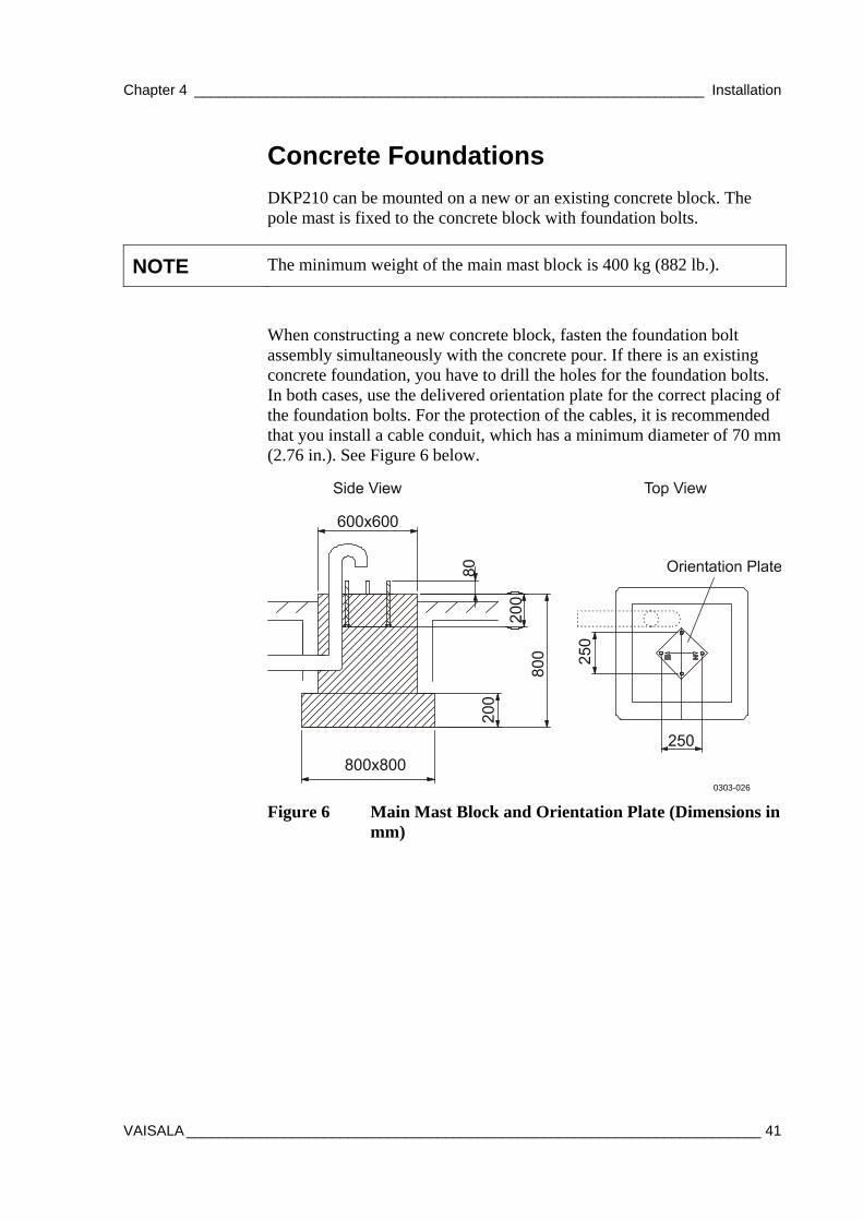
DKP210 can be mounted on a new or an existing concrete block. The pole mast is fixed to the concrete block with foundation bolts.
NOTE The minimum weight of the main mast block is 400 kg (882 lb.).
When constructing a new concrete block, fasten the foundation bolt assembly simultaneously with the concrete pour. If there is an existing concrete foundation, you have to drill the holes for the foundation bolts. In both cases, use the delivered orientation plate for the correct placing of the foundation bolts. For the protection of the cables, it is recommended that you install a cable conduit, which has a minimum diameter of 70 mm (2.76 in.). See Figure 6 below.
0303-026
Figure 6 Main Mast Block and Orientation Plate (Dimensions in mm)
User's Guide ______________________________________________________________________
42 __________________________________________________________________ M211296EN-A
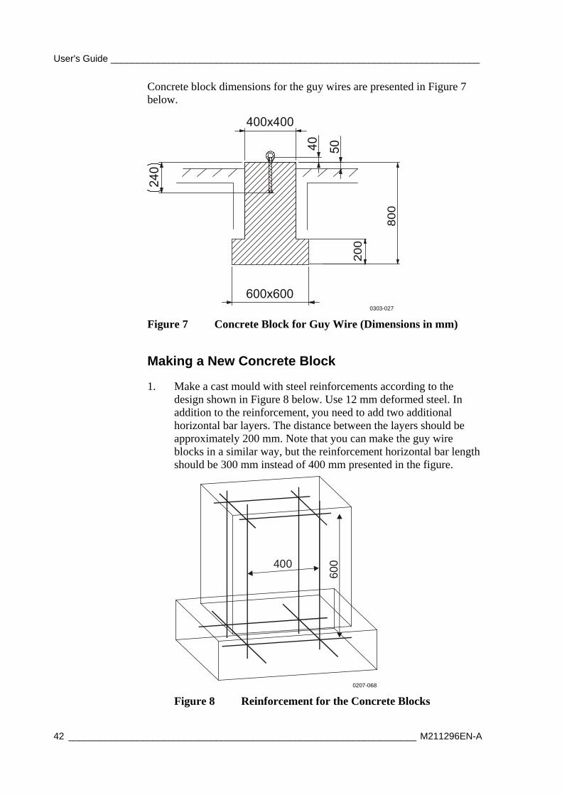
Concrete block dimensions for the guy wires are presented in Figure 7 below.
0303-027
Figure 7 Concrete Block for Guy Wire (Dimensions in mm)
Making a New Concrete Block
1. Make a cast mould with steel reinforcements according to the design shown in Figure 8 below. Use 12 mm deformed steel. In addition to the reinforcement, you need to add two additional horizontal bar layers. The distance between the layers should be approximately 200 mm. Note that you can make the guy wire blocks in a similar way, but the reinforcement horizontal bar length should be 300 mm instead of 400 mm presented in the figure.
400
600
0207-068
Figure 8 Reinforcement for the Concrete Blocks
Chapter 4 _______________________________________________________________ Installation
VAISALA _______________________________________________________________________ 43
2. If necessary, place the cable duct tubes into the casting mould prior to casting. The recommended inner diameter of the duct tube is 70 mm (2.76 in.).
3. Place the steel reinforcement into the casting mould.
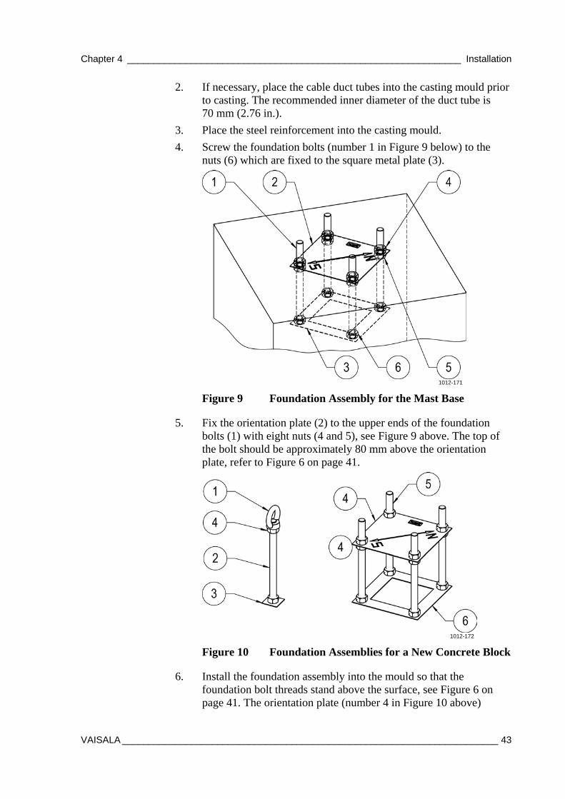
4. Screw the foundation bolts (number 1 in Figure 9 below) to the nuts (6) which are fixed to the square metal plate (3).
1012-171
Figure 9 Foundation Assembly for the Mast Base
5. Fix the orientation plate (2) to the upper ends of the foundation bolts (1) with eight nuts (4 and 5), see Figure 9 above. The top of the bolt should be approximately 80 mm above the orientation plate, refer to Figure 6 on page 41.
1012-172
Figure 10 Foundation Assemblies for a New Concrete Block
6. Install the foundation assembly into the mould so that the foundation bolt threads stand above the surface, see Figure 6 on page 41. The orientation plate (number 4 in Figure 10 above)
User's Guide ______________________________________________________________________
44 __________________________________________________________________ M211296EN-A
should be at the same height as the top of the finalized concrete block. Protect the threads of the bolts above the orientation plate, for example, by taping them. Also check the correct alignment of the foundation assembly with the orientation plate. "N" should face north and "S" should face south.
7. For the guy wires, fix the foundation bolt (number 2 in Figure 10 on page 43) to the plate with a nut (3). Fix the eye nut (1) to the other end of the foundation bolt. Level the assembly so that the top of the bolt will be 40 mm above the concrete in the finalized block. The eye nut will then be one centimeter above the finalized concrete block.
8. Pour in the concrete. Finish the concrete block.
Using an Existing Concrete Block
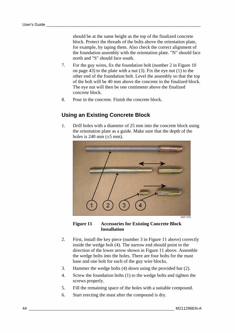
1. Drill holes with a diameter of 25 mm into the concrete block using the orientation plate as a guide. Make sure that the depth of the holes is 240 mm (±5 mm).
0207-070
Figure 11 Accessories for Existing Concrete Block Installation
2. First, install the key piece (number 3 in Figure 11 above) correctly inside the wedge bolt (4). The narrow end should point to the direction of the lower arrow shown in Figure 11 above. Assemble the wedge bolts into the holes. There are four bolts for the mast base and one bolt for each of the guy wire blocks.
3. Hammer the wedge bolts (4) down using the provided bar (2).
4. Screw the foundation bolts (1) to the wedge bolts and tighten the screws properly.
5. Fill the remaining space of the holes with a suitable compound.
6. Start erecting the mast after the compound is dry.
Chapter 4 _______________________________________________________________ Installation
VAISALA _______________________________________________________________________ 45
Mechanical Installation Procedure Reserve at least a full day for the mechanical installation, especially if you do not have previous experience with weather stations.
CAUTION Wear a safety helmet when installing the mast. Preferably do not install the mast alone.
The mechanical installation consists of the following phases:
1. Installing Mast DKP210 as described on page 46.
2. Installing Ultrasonic Wind Sensor WMT70 as described on page 62 or Installing Mechanical Wind Sensor Set WA15 as described on page 70.
3. Installing GSM/GPRS Antenna as described on page 72.
4. Installing Solar Panel as described on page 73.
5. Erecting Mast DKP210 as described on page 56.
6. Installing Sensor Support as described on page 77.
7. Installing Air Temperature and Relative Humidity Probe HMP155 as described on page 80.
8. Installing Snow Depth Sensor IRU-9429 as described on page 85.
9. Installing Pyranometer CMP6 as described on page 82.
10. Installing Soil Temperature Sensor QMT110 as described on page 86.
11. Installing Rain Gauge RG13(H) as described on page 87.
12. Installing Enclosure as described on page 90, comprising the following phases:
a. Installing Enclosure to the Mast as described on page 91 or Installing Enclosure to the Wall as described on page 93.
b. Grounding the Enclosure as described on page 94.
c. Installing Backup Batteries as described on page 94
d. Preparing GSM/GPRS Modem as described on page 96
13. Connecting Sensor Cables as described on page 97.
14. Powering Up the System as described on page 99.
After the mechanical installation, AWS330 is configured with a laptop PC and AWS Client software as described in Chapter 5, Software Configuration and Operation, on page 101.

User's Guide ______________________________________________________________________
46 __________________________________________________________________ M211296EN-A
Installing Mast DKP210 DKP210 is a 10-meter tiltable mast. The mast is designed to withstand high wind conditions, up to 50 m/s of maximum wind speed, with a standard set of guy wires. The plate of the pedestal tube is made of stainless steel with a powder coating resistant to corrosion. The material of the lifting rod and mast tubes is anodized aluminum.
CAUTION Do not install the mast when wind speed is over 7 m/s.
NOTE Wind sensors WMT703 and WA15 positioned on top of the mast require exact bearings (north, south). Take time to position the mast correctly, as instructed here, and verify the directions carefully. This will make correct aligning of the wind sensors significantly easier.
Chapter 4 _______________________________________________________________ Installation
VAISALA _______________________________________________________________________ 47
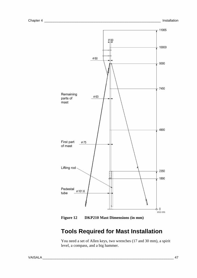
1012-201
Figure 12 DKP210 Mast Dimensions (in mm)
Tools Required for Mast Installation
You need a set of Allen keys, two wrenches (17 and 30 mm), a spirit level, a compass, and a big hammer.
User's Guide ______________________________________________________________________
48 __________________________________________________________________ M211296EN-A
Mast Installation Procedure
To assemble the mast, follow the work order below:
1. Attach the 2-meter-high pedestal tube to the concrete foundation.
2. Lift the first part of the mast to the upper end of the pedestal tube and assemble the hinge axle.
3. Attach the lifting rod to the clamp preinstalled to the first part of the mast.
4. Assemble the remaining parts of the mast.
5. Lift the upper end of the mast on the tilting support and secure the tilting support to the mast using the provided strap.
6. Attach the guy wires to the uppermost part of the mast.
7. Assemble the rod holders to the lightning rod and attach the assembly to the mast.
8. Attach the winch and route the winch wire to the appropriate guides.
9. Attach the jacketed copper grounding wire to the isolated guy wire 3 with the cable ties.
10. Erect the mast with the winch and secure the hinge with the bolts.
11. Connect the guy wires with fasteners to their foundations and mark them with the cable shrouds.
12. Tilt the mast down by opening the detachable guy wire 1 to verify that the installation is secure.
13. Install any other devices that will be installed to the tiltable part of the mast and attach the cables to the mast with cable ties.
14. Erect the mast with the winch and secure the hinge with the bolts.
15. Remove the winch and assemble the devices to the pedestal tube.
For detailed instructions, refer to the following sections.
Chapter 4 _______________________________________________________________ Installation
VAISALA _______________________________________________________________________ 49
Installing the Pedestal Tube
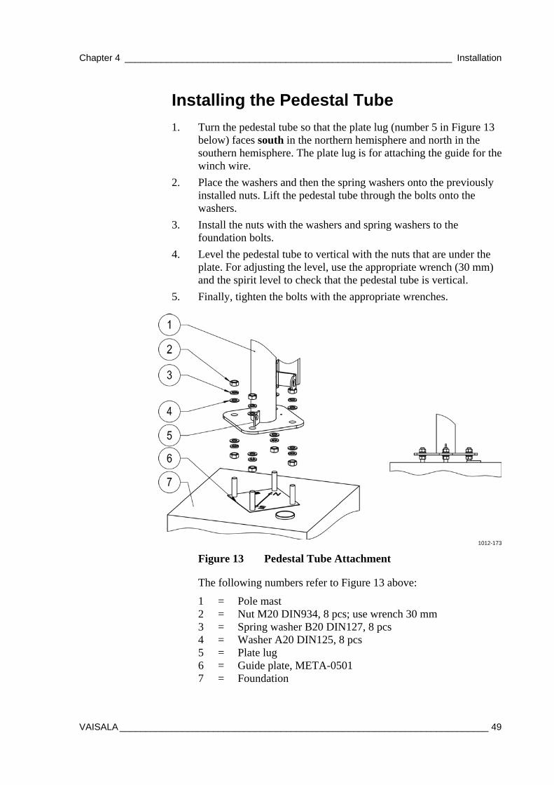
1. Turn the pedestal tube so that the plate lug (number 5 in Figure 13 below) faces south in the northern hemisphere and north in the southern hemisphere. The plate lug is for attaching the guide for the winch wire.
2. Place the washers and then the spring washers onto the previously installed nuts. Lift the pedestal tube through the bolts onto the washers.
3. Install the nuts with the washers and spring washers to the foundation bolts.
4. Level the pedestal tube to vertical with the nuts that are under the plate. For adjusting the level, use the appropriate wrench (30 mm) and the spirit level to check that the pedestal tube is vertical.
5. Finally, tighten the bolts with the appropriate wrenches.
1012-173
Figure 13 Pedestal Tube Attachment
The following numbers refer to Figure 13 above:
1 = Pole mast 2 = Nut M20 DIN934, 8 pcs; use wrench 30 mm 3 = Spring washer B20 DIN127, 8 pcs 4 = Washer A20 DIN125, 8 pcs 5 = Plate lug 6 = Guide plate, META-0501 7 = Foundation
User's Guide ______________________________________________________________________
50 __________________________________________________________________ M211296EN-A
Connecting the First Part of the Mast to the Pedestal Tube
To connect the first part of the mast to the pedestal tube, install the axle for the hinge. Take the axle (number 3 in Figure 14 below) from the plastic bag labeled "Hinge Set".
1. Thread the Allen bolt (4) with the washers to one end of the axle.
2. Lift the first part of the mast (1) end on the hinge and install the axle.
3. Thread the Allen bolt (4) with the washers to the other end of the axle and tighten both ends with an Allen key.
1012-174
Figure 14 Hinge Axle Installation
The following numbers refer to Figure 14 above:
1 = First part of the mast 2 = Pedestal tube 3 = Axle for hinge 4 = Allen bolt M8x25 DIN912 A4, 2 pcs; use Allen key 6 mm 5 = Spring washer B8 DIN127 A4, 2 pcs 6 = Washer A8.4 DIN9021 A4, 2 pcs
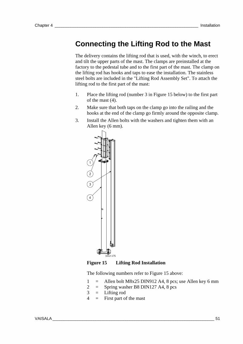
Chapter 4 _______________________________________________________________ Installation
VAISALA _______________________________________________________________________ 51
Connecting the Lifting Rod to the Mast
The delivery contains the lifting rod that is used, with the winch, to erect and tilt the upper parts of the mast. The clamps are preinstalled at the factory to the pedestal tube and to the first part of the mast. The clamp on the lifting rod has hooks and taps to ease the installation. The stainless steel bolts are included in the "Lifting Rod Assembly Set". To attach the lifting rod to the first part of the mast:
1. Place the lifting rod (number 3 in Figure 15 below) to the first part of the mast (4).
2. Make sure that both taps on the clamp go into the railing and the hooks at the end of the clamp go firmly around the opposite clamp.
3. Install the Allen bolts with the washers and tighten them with an Allen key (6 mm).
1012-175
Figure 15 Lifting Rod Installation
The following numbers refer to Figure 15 above:
1 = Allen bolt M8x25 DIN912 A4, 8 pcs; use Allen key 6 mm2 = Spring washer B8 DIN127 A4, 8 pcs 3 = Lifting rod 4 = First part of the mast
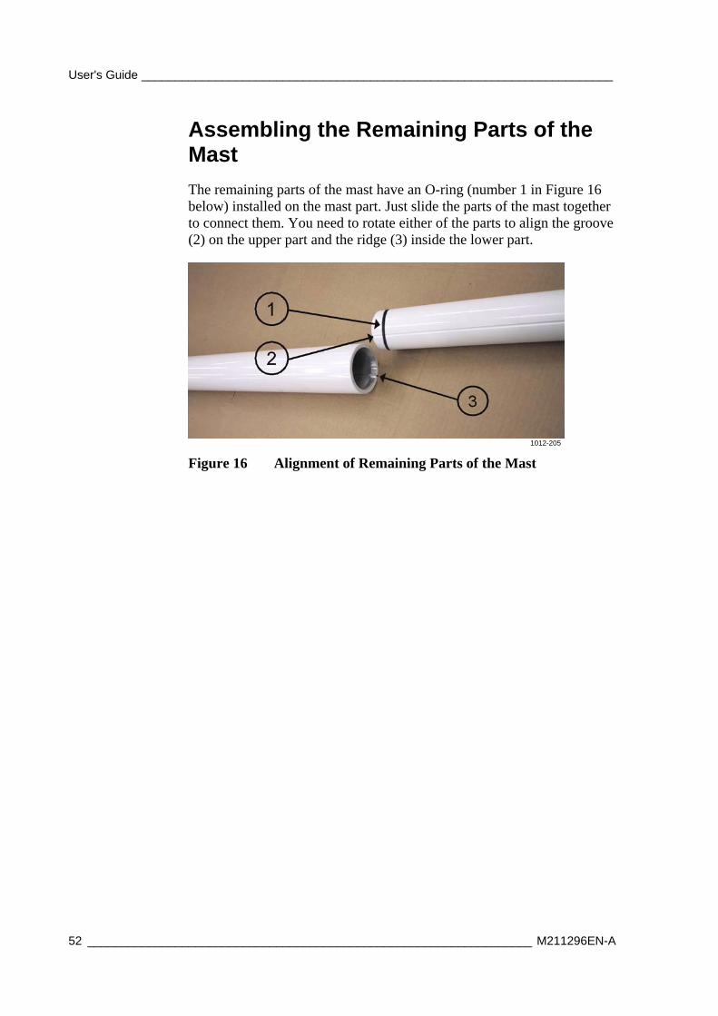
User's Guide ______________________________________________________________________
52 __________________________________________________________________ M211296EN-A
Assembling the Remaining Parts of the Mast
The remaining parts of the mast have an O-ring (number 1 in Figure 16 below) installed on the mast part. Just slide the parts of the mast together to connect them. You need to rotate either of the parts to align the groove (2) on the upper part and the ridge (3) inside the lower part.
1012-205
Figure 16 Alignment of Remaining Parts of the Mast
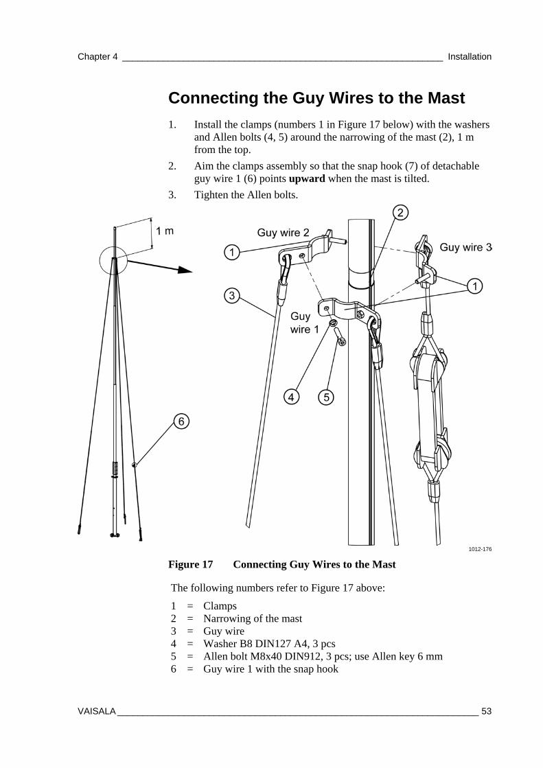
Chapter 4 _______________________________________________________________ Installation
VAISALA _______________________________________________________________________ 53
Connecting the Guy Wires to the Mast
1. Install the clamps (numbers 1 in Figure 17 below) with the washers and Allen bolts (4, 5) around the narrowing of the mast (2), 1 m from the top.
2. Aim the clamps assembly so that the snap hook (7) of detachable guy wire 1 (6) points upward when the mast is tilted.
3. Tighten the Allen bolts.
1012-176
Figure 17 Connecting Guy Wires to the Mast
The following numbers refer to Figure 17 above:
1 = Clamps 2 = Narrowing of the mast 3 = Guy wire 4 = Washer B8 DIN127 A4, 3 pcs 5 = Allen bolt M8x40 DIN912, 3 pcs; use Allen key 6 mm 6 = Guy wire 1 with the snap hook
User's Guide ______________________________________________________________________
54 __________________________________________________________________ M211296EN-A
Installing the Lightning Rod
To install the lightning rod, proceed as follows:
1. Slide the lightning rod (number 1 in Figure 18 on page 55) to the holes in the lightning rod holders (2) and attach the rod to the holders using the fastening plates (6).
2. Attach the lighting rod holders to the mast so that they point to the same direction as the isolated guy wire 3 (number 8 in Figure 18 on page 55; see also Figure 4 on page 37).
3. Before erecting the mast, attach the grounding cable to the isolated guy wire 3 with cable ties (9), starting below the isolation block.
NOTE Leave some extra cable between the lightning rod and the wire clip on the guy wire to ensure that the guy wire does not pull the lightning rod downward.
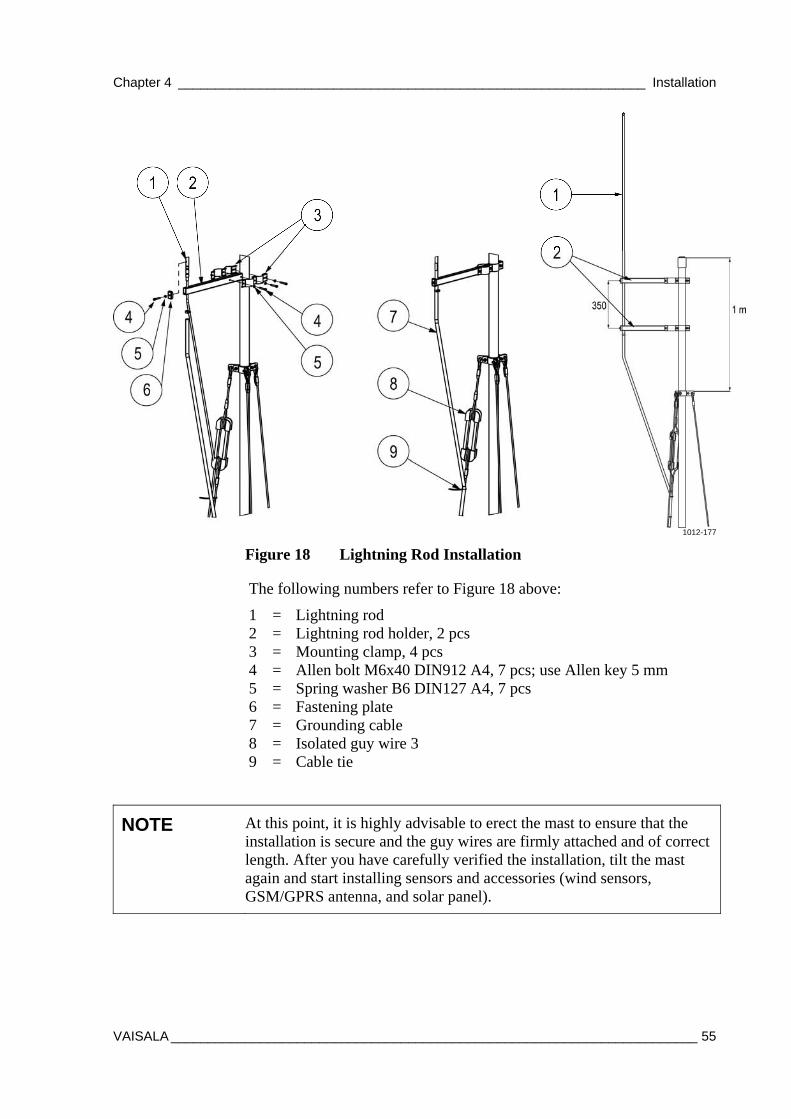
Chapter 4 _______________________________________________________________ Installation
VAISALA _______________________________________________________________________ 55
1012-177
Figure 18 Lightning Rod Installation
The following numbers refer to Figure 18 above:
1 = Lightning rod 2 = Lightning rod holder, 2 pcs 3 = Mounting clamp, 4 pcs 4 = Allen bolt M6x40 DIN912 A4, 7 pcs; use Allen key 5 mm 5 = Spring washer B6 DIN127 A4, 7 pcs 6 = Fastening plate 7 = Grounding cable 8 = Isolated guy wire 3 9 = Cable tie
NOTE At this point, it is highly advisable to erect the mast to ensure that the installation is secure and the guy wires are firmly attached and of correct length. After you have carefully verified the installation, tilt the mast again and start installing sensors and accessories (wind sensors, GSM/GPRS antenna, and solar panel).
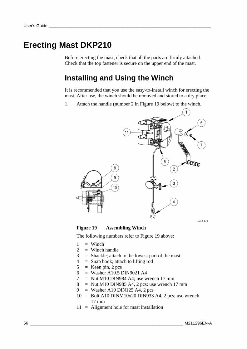
User's Guide ______________________________________________________________________
56 __________________________________________________________________ M211296EN-A
Erecting Mast DKP210 Before erecting the mast, check that all the parts are firmly attached. Check that the top fastener is secure on the upper end of the mast.
Installing and Using the Winch
It is recommended that you use the easy-to-install winch for erecting the mast. After use, the winch should be removed and stored to a dry place.
1. Attach the handle (number 2 in Figure 19 below) to the winch.
1012-179
Figure 19 Assembling Winch
The following numbers refer to Figure 19 above:
1 = Winch 2 = Winch handle 3 = Shackle; attach to the lowest part of the mast. 4 = Snap hook; attach to lifting rod 5 = Keen pin, 2 pcs 6 = Washer A10.5 DIN9021 A4 7 = Nut M10 DIN984 A4; use wrench 17 mm 8 = Nut M10 DIN985 A4, 2 pcs; use wrench 17 mm 9 = Washer A10 DIN125 A4, 2 pcs 10 = Bolt A10 DINM10x20 DIN933 A4, 2 pcs; use wrench
17 mm 11 = Alignment hole for mast installation
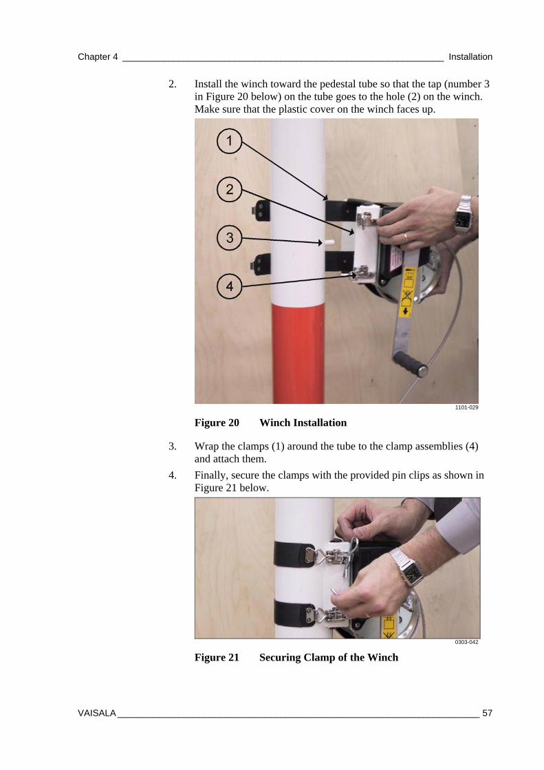
Chapter 4 _______________________________________________________________ Installation
VAISALA _______________________________________________________________________ 57
2. Install the winch toward the pedestal tube so that the tap (number 3 in Figure 20 below) on the tube goes to the hole (2) on the winch. Make sure that the plastic cover on the winch faces up.
1101-029
Figure 20 Winch Installation
3. Wrap the clamps (1) around the tube to the clamp assemblies (4) and attach them.
4. Finally, secure the clamps with the provided pin clips as shown in Figure 21 below.
0303-042
Figure 21 Securing Clamp of the Winch
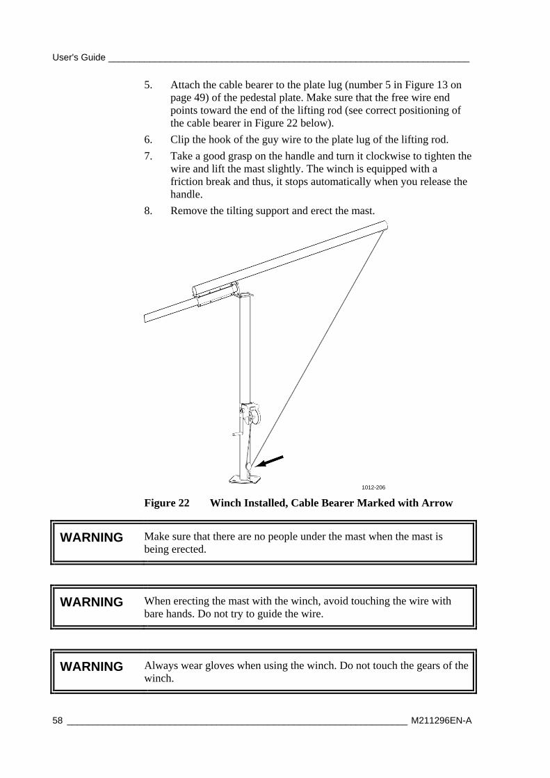
User's Guide ______________________________________________________________________
58 __________________________________________________________________ M211296EN-A
5. Attach the cable bearer to the plate lug (number 5 in Figure 13 on page 49) of the pedestal plate. Make sure that the free wire end points toward the end of the lifting rod (see correct positioning of the cable bearer in Figure 22 below).
6. Clip the hook of the guy wire to the plate lug of the lifting rod.
7. Take a good grasp on the handle and turn it clockwise to tighten the wire and lift the mast slightly. The winch is equipped with a friction break and thus, it stops automatically when you release the handle.
8. Remove the tilting support and erect the mast.
1012-206
Figure 22 Winch Installed, Cable Bearer Marked with Arrow
WARNING Make sure that there are no people under the mast when the mast is being erected.
WARNING When erecting the mast with the winch, avoid touching the wire with bare hands. Do not try to guide the wire.
WARNING Always wear gloves when using the winch. Do not touch the gears of the winch.
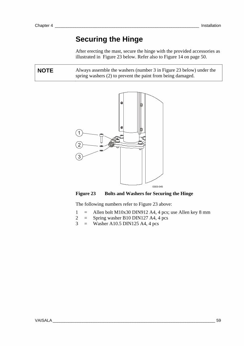
Chapter 4 _______________________________________________________________ Installation
VAISALA _______________________________________________________________________ 59
Securing the Hinge
After erecting the mast, secure the hinge with the provided accessories as illustrated in Figure 23 below. Refer also to Figure 14 on page 50.
NOTE Always assemble the washers (number 3 in Figure 23 below) under the spring washers (2) to prevent the paint from being damaged.
0303-045
Figure 23 Bolts and Washers for Securing the Hinge
The following numbers refer to Figure 23 above:
1 = Allen bolt M10x30 DIN912 A4, 4 pcs; use Allen key 8 mm 2 = Spring washer B10 DIN127 A4, 4 pcs 3 = Washer A10.5 DIN125 A4, 4 pcs
User's Guide ______________________________________________________________________
60 __________________________________________________________________ M211296EN-A
Connecting the Guy Wires to the Concrete Blocks
1. For the guy wires 2 and 3, connect the U-bolt (number 4 in Figure 24 on page 61) to the eye nut (5) installed on the concrete block. Slide the strap (3) onto the U-bolt and thread the nuts.
2. For the guy wire 1, connect the U-bolt to the eye nut with an additional bow shackle to enable easy releasing of the wire. The strap is used the same way as with the guy wires 2 and 3.
3. Guide the guy wire through the strap (3) around the wedge (9) and back through the strap. Pull the loose wire through the strap and secure it with wire clips.
4. After assembling the wire clips properly, tension the guy wire by tightening the nuts to slide the strap until the initial tension of the guy wires is sufficient.
NOTE When tensioning the guy wires, make sure that the mast remains straight and that all the guy wires are equally tensioned.
5. Finally, place the black and yellow cable shrouds around the guy wires. There is one package of shrouds for each wire. Place the extra guy wire inside the cable shrouds.
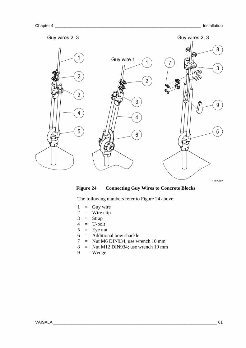
Chapter 4 _______________________________________________________________ Installation
VAISALA _______________________________________________________________________ 61
1012-207
Figure 24 Connecting Guy Wires to Concrete Blocks
The following numbers refer to Figure 24 above:
1 = Guy wire 2 = Wire clip 3 = Strap 4 = U-bolt 5 = Eye nut 6 = Additional bow shackle 7 = Nut M6 DIN934; use wrench 10 mm 8 = Nut M12 DIN934; use wrench 19 mm 9 = Wedge
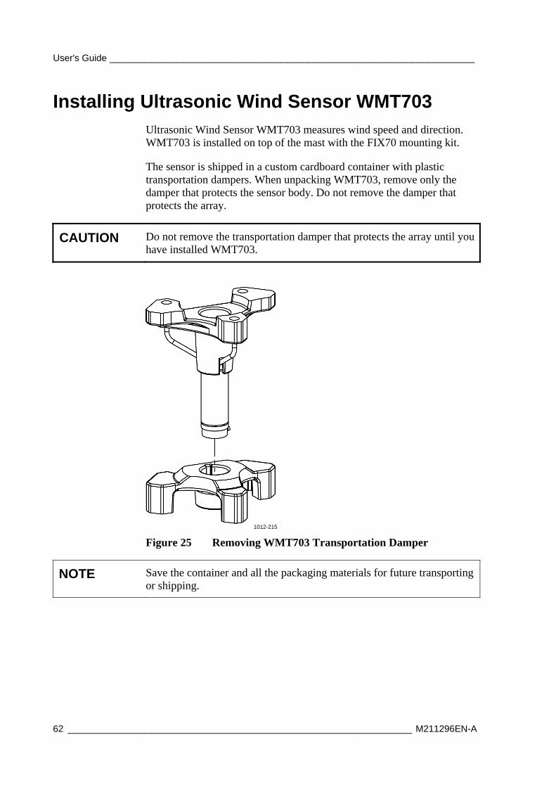
User's Guide ______________________________________________________________________
62 __________________________________________________________________ M211296EN-A
Installing Ultrasonic Wind Sensor WMT703 Ultrasonic Wind Sensor WMT703 measures wind speed and direction. WMT703 is installed on top of the mast with the FIX70 mounting kit.
The sensor is shipped in a custom cardboard container with plastic transportation dampers. When unpacking WMT703, remove only the damper that protects the sensor body. Do not remove the damper that protects the array.
CAUTION Do not remove the transportation damper that protects the array until you have installed WMT703.
1012-215
Figure 25 Removing WMT703 Transportation Damper
NOTE Save the container and all the packaging materials for future transporting or shipping.
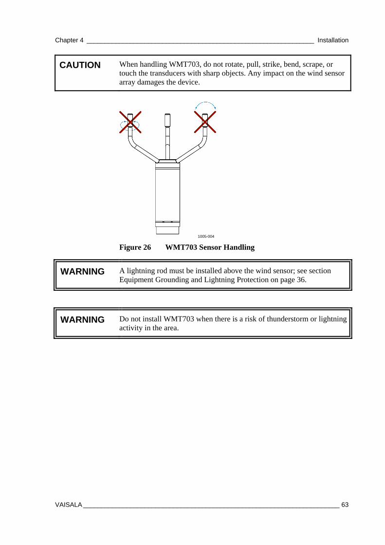
Chapter 4 _______________________________________________________________ Installation
VAISALA _______________________________________________________________________ 63
CAUTION When handling WMT703, do not rotate, pull, strike, bend, scrape, or touch the transducers with sharp objects. Any impact on the wind sensor array damages the device.
1005-004
Figure 26 WMT703 Sensor Handling
WARNING A lightning rod must be installed above the wind sensor; see section Equipment Grounding and Lightning Protection on page 36.
WARNING Do not install WMT703 when there is a risk of thunderstorm or lightning activity in the area.
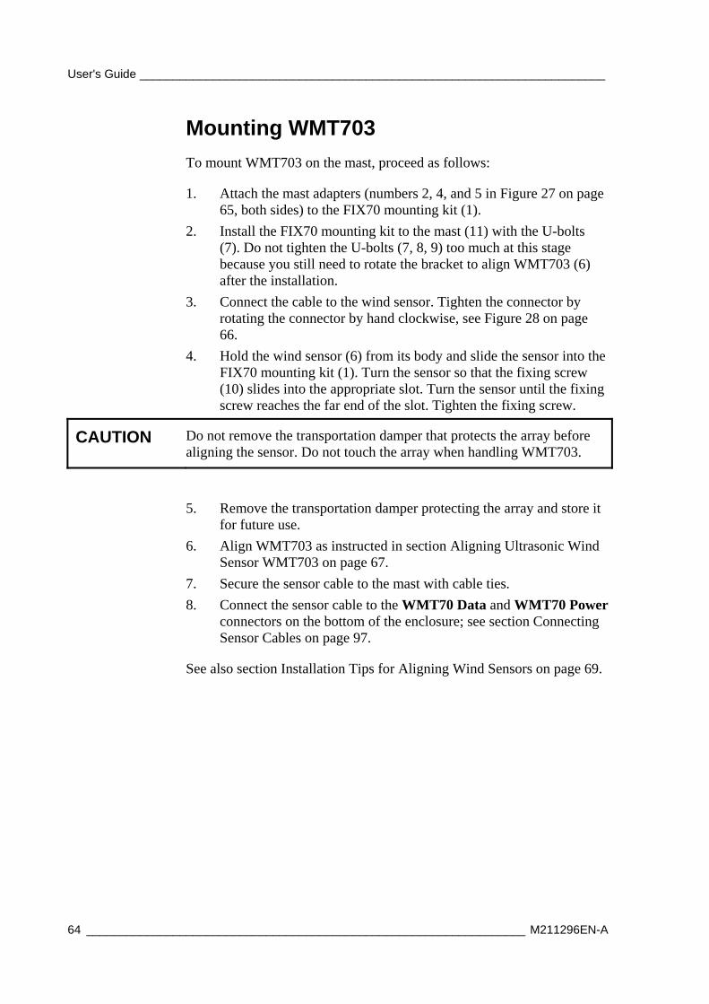
User's Guide ______________________________________________________________________
64 __________________________________________________________________ M211296EN-A
Mounting WMT703
To mount WMT703 on the mast, proceed as follows:
1. Attach the mast adapters (numbers 2, 4, and 5 in Figure 27 on page 65, both sides) to the FIX70 mounting kit (1).
2. Install the FIX70 mounting kit to the mast (11) with the U-bolts (7). Do not tighten the U-bolts (7, 8, 9) too much at this stage because you still need to rotate the bracket to align WMT703 (6) after the installation.
3. Connect the cable to the wind sensor. Tighten the connector by rotating the connector by hand clockwise, see Figure 28 on page 66.
4. Hold the wind sensor (6) from its body and slide the sensor into the FIX70 mounting kit (1). Turn the sensor so that the fixing screw (10) slides into the appropriate slot. Turn the sensor until the fixing screw reaches the far end of the slot. Tighten the fixing screw.
CAUTION Do not remove the transportation damper that protects the array before aligning the sensor. Do not touch the array when handling WMT703.
5. Remove the transportation damper protecting the array and store it for future use.
6. Align WMT703 as instructed in section Aligning Ultrasonic Wind Sensor WMT703 on page 67.
7. Secure the sensor cable to the mast with cable ties.
8. Connect the sensor cable to the WMT70 Data and WMT70 Power connectors on the bottom of the enclosure; see section Connecting Sensor Cables on page 97.
See also section Installation Tips for Aligning Wind Sensors on page 69.
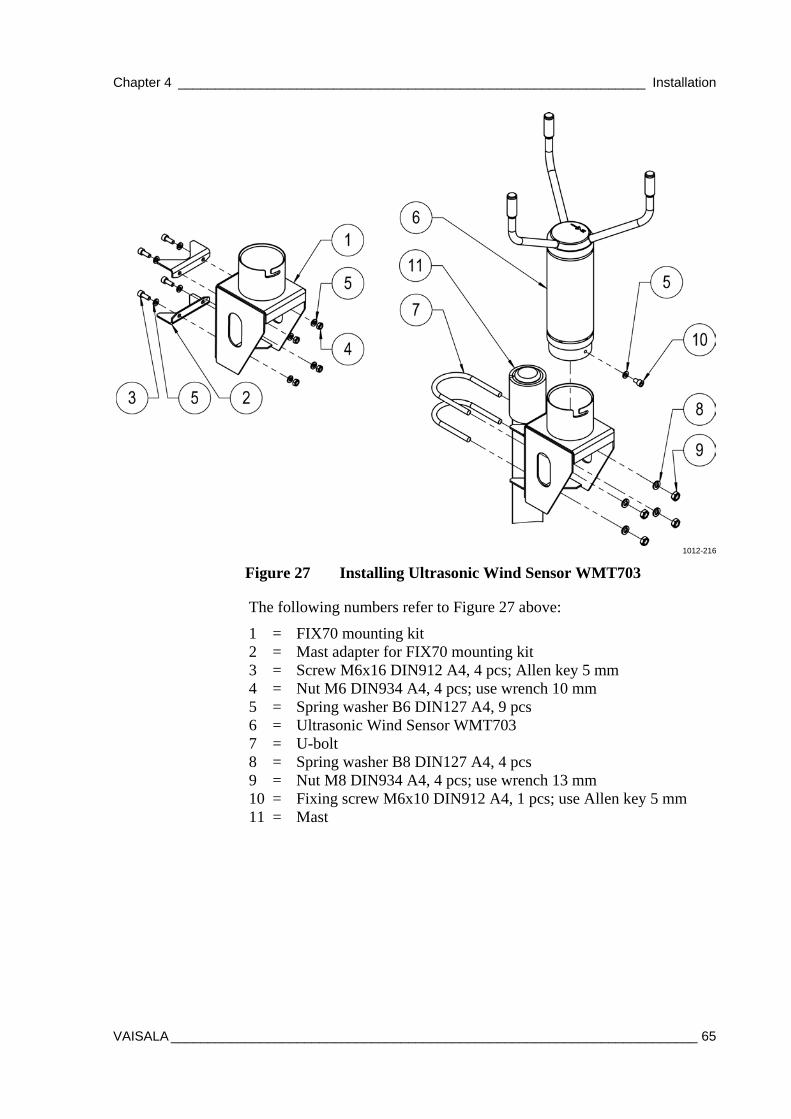
Chapter 4 _______________________________________________________________ Installation
VAISALA _______________________________________________________________________ 65
1012-216
Figure 27 Installing Ultrasonic Wind Sensor WMT703
The following numbers refer to Figure 27 above:
1 = FIX70 mounting kit 2 = Mast adapter for FIX70 mounting kit 3 = Screw M6x16 DIN912 A4, 4 pcs; Allen key 5 mm 4 = Nut M6 DIN934 A4, 4 pcs; use wrench 10 mm 5 = Spring washer B6 DIN127 A4, 9 pcs 6 = Ultrasonic Wind Sensor WMT703 7 = U-bolt 8 = Spring washer B8 DIN127 A4, 4 pcs 9 = Nut M8 DIN934 A4, 4 pcs; use wrench 13 mm 10 = Fixing screw M6x10 DIN912 A4, 1 pcs; use Allen key 5 mm 11 = Mast
User's Guide ______________________________________________________________________
66 __________________________________________________________________ M211296EN-A
1004-084
Figure 28 Tightening the Connector
The following number refers to Figure 28 above:
1 = Tighten the connector by rotating the ribbed part of the connector by hand. Do not use tools.
NOTE Verify that the connector is properly tightened to avoid water leakage and damage to the sensor. If water leaks into the connector, the warranty for WMT703 is voided.
Checklist for Connection Cables
Take the following issues into account when installing WMT703:
- Routing of the cables depends on the mounting option selected for WMT703. When mounting to a mast, the cable can be routed either outside or inside the mast, depending on the mast type and other equipment (for instance, lightning rods) installed to the mast.
- Make sure that the cable is properly attached to the mast or cross arm before starting the installation. Otherwise, it may slip and fall down during the installation.
- It is important to attach the cable properly to avoid strain to the connector. Too much strain may cause the cable to fall off, damage the cable or connector, or make the cable or connector susceptible to water leakage. The recommended minimum bending radius for the cable is 70 mm.
WARNING Make sure that you connect only de-energized wires.
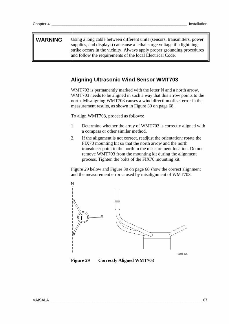
Chapter 4 _______________________________________________________________ Installation
VAISALA _______________________________________________________________________ 67
WARNING Using a long cable between different units (sensors, transmitters, power supplies, and displays) can cause a lethal surge voltage if a lightning strike occurs in the vicinity. Always apply proper grounding procedures and follow the requirements of the local Electrical Code.
Aligning Ultrasonic Wind Sensor WMT703
WMT703 is permanently marked with the letter N and a north arrow. WMT703 needs to be aligned in such a way that this arrow points to the north. Misaligning WMT703 causes a wind direction offset error in the measurement results, as shown in Figure 30 on page 68.
To align WMT703, proceed as follows:
1. Determine whether the array of WMT703 is correctly aligned with a compass or other similar method.
2. If the alignment is not correct, readjust the orientation: rotate the FIX70 mounting kit so that the north arrow and the north transducer point to the north in the measurement location. Do not remove WMT703 from the mounting kit during the alignment process. Tighten the bolts of the FIX70 mounting kit.
Figure 29 below and Figure 30 on page 68 show the correct alignment and the measurement error caused by misalignment of WMT703.
0208-025
Figure 29 Correctly Aligned WMT703
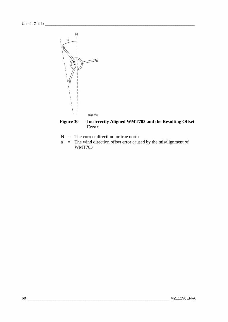
User's Guide ______________________________________________________________________
68 __________________________________________________________________ M211296EN-A
1001-018
Figure 30 Incorrectly Aligned WMT703 and the Resulting Offset Error
N = The correct direction for true north a = The wind direction offset error caused by the misalignment of
WMT703
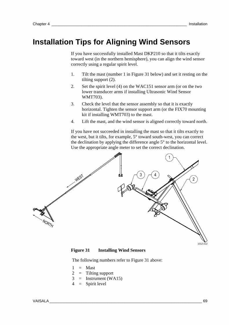
Chapter 4 _______________________________________________________________ Installation
VAISALA _______________________________________________________________________ 69
Installation Tips for Aligning Wind Sensors If you have successfully installed Mast DKP210 so that it tilts exactly toward west (in the northern hemisphere), you can align the wind sensor correctly using a regular spirit level.
1. Tilt the mast (number 1 in Figure 31 below) and set it resting on the tilting support (2).
2. Set the spirit level (4) on the WAC151 sensor arm (or on the two lower transducer arms if installing Ultrasonic Wind Sensor WMT703).
3. Check the level that the sensor assembly so that it is exactly horizontal. Tighten the sensor support arm (or the FIX70 mounting kit if installing WMT703) to the mast.
4. Lift the mast, and the wind sensor is aligned correctly toward north.
If you have not succeeded in installing the mast so that it tilts exactly to the west, but it tilts, for example, 5° toward south-west, you can correct the declination by applying the difference angle 5° to the horizontal level. Use the appropriate angle meter to set the correct declination.
1012-212
Figure 31 Installing Wind Sensors
The following numbers refer to Figure 31 above:
1 = Mast 2 = Tilting support 3 = Instrument (WA15) 4 = Spirit level
User's Guide ______________________________________________________________________
70 __________________________________________________________________ M211296EN-A
Installing Mechanical Wind Sensor Set WA15 Mechanical Wind Sensor Set WA15 consists of a Vaisala Anemometer WAA151, a Vaisala Wind Vane WAV151, a cross arm WAC151, a junction box, and cabling.
Install WA15 as follows:
1. Attach the cross arm to the top of a pole mast with the mounting clamp. Check that vane end of the cross arm is pointing north as shown in Figure 31 on page 69.
2. Mount the sensors onto the cross arm as shown in Figure 32 on page 71.
3. Bind the cables to the mast with cable ties.
WARNING Using a long cable between different units (sensors, transmitters, power supplies, and displays) can cause a lethal surge voltage if a lightning strike occurs in the vicinity. Always ground the mast equipment case close to the mast with a short, low-resistance cable.
4. Connect the sensor cables DRW222446 and DRW222447 to the WIND1 and WIND2 connectors on the bottom of the enclosure; see section Connecting Sensor Cables on page 97.
See also section Installation Tips for Aligning Wind Sensors on page 69.
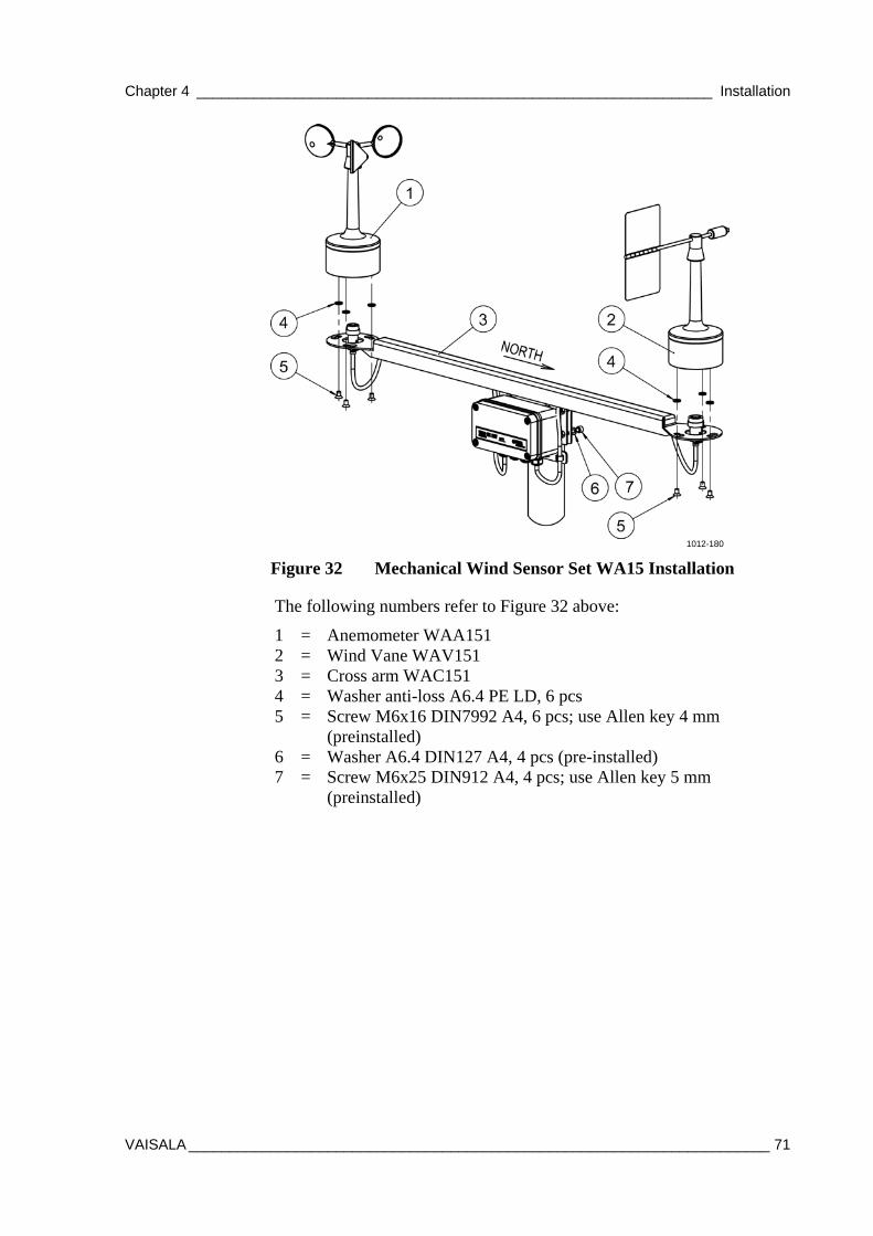
Chapter 4 _______________________________________________________________ Installation
VAISALA _______________________________________________________________________ 71
1012-180
Figure 32 Mechanical Wind Sensor Set WA15 Installation
The following numbers refer to Figure 32 above:
1 = Anemometer WAA151 2 = Wind Vane WAV151 3 = Cross arm WAC151 4 = Washer anti-loss A6.4 PE LD, 6 pcs 5 = Screw M6x16 DIN7992 A4, 6 pcs; use Allen key 4 mm
(preinstalled) 6 = Washer A6.4 DIN127 A4, 4 pcs (pre-installed) 7 = Screw M6x25 DIN912 A4, 4 pcs; use Allen key 5 mm
(preinstalled)
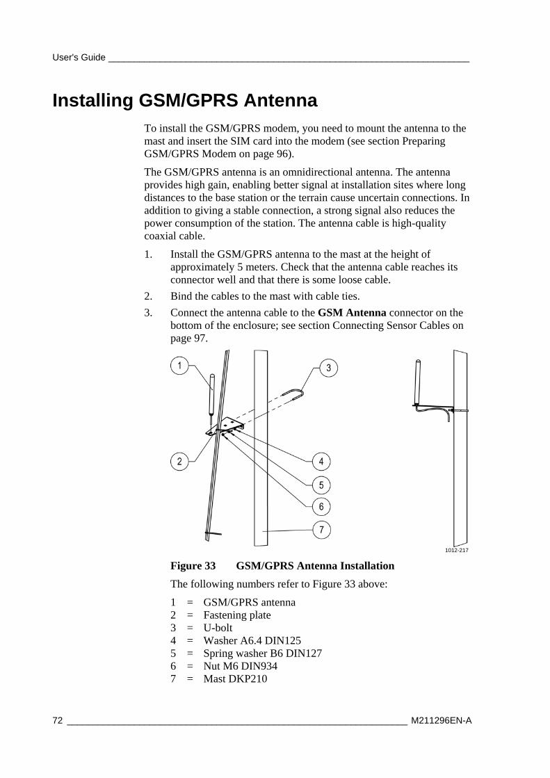
User's Guide ______________________________________________________________________
72 __________________________________________________________________ M211296EN-A
Installing GSM/GPRS Antenna To install the GSM/GPRS modem, you need to mount the antenna to the mast and insert the SIM card into the modem (see section Preparing GSM/GPRS Modem on page 96).
The GSM/GPRS antenna is an omnidirectional antenna. The antenna provides high gain, enabling better signal at installation sites where long distances to the base station or the terrain cause uncertain connections. In addition to giving a stable connection, a strong signal also reduces the power consumption of the station. The antenna cable is high-quality coaxial cable.
1. Install the GSM/GPRS antenna to the mast at the height of approximately 5 meters. Check that the antenna cable reaches its connector well and that there is some loose cable.
2. Bind the cables to the mast with cable ties.
3. Connect the antenna cable to the GSM Antenna connector on the bottom of the enclosure; see section Connecting Sensor Cables on page 97.
1012-217
Figure 33 GSM/GPRS Antenna Installation
The following numbers refer to Figure 33 above:
1 = GSM/GPRS antenna 2 = Fastening plate 3 = U-bolt 4 = Washer A6.4 DIN125 5 = Spring washer B6 DIN127 6 = Nut M6 DIN934 7 = Mast DKP210
Chapter 4 _______________________________________________________________ Installation
VAISALA _______________________________________________________________________ 73
Installing Solar Panel SOLAR33 Solar Panel SOLAR33 is a custom-designed module incorporating high-power efficiency and quality. The 33 W panel contains 36 polycrystalline silicon cells. The SOLAR33 modules are lightweight and have high power and a robust construction.
The cells are protected from dirt, moisture and mechanical impact using a tempered, low-iron glass front. The solar circuit is laminated using EVA (Ethylene Vinyl Acetate) between tempered glass and a durable, multi-layered polymer back sheet for superior moisture resistance.
WARNING Photovoltaic modules generate direct current (DC) when exposed to sunlight or other sources of light. Although single modules produce low voltage and current, shocks and burns can still result from contact with module output wiring.
CAUTION Handle the solar panel with care: impact on the front or rear surface can damage the module. Do not bend the panel.
CAUTION When working with the panel, use properly insulated tools and wear rubber gloves.
NOTE The rays of the sun should be perpendicular to the panel. In other words, sunlight should hit the panel at a 90° angle.
NOTE Do not concentrate light on the panel in an attempt to increase its power output.
User's Guide ______________________________________________________________________
74 __________________________________________________________________ M211296EN-A
Install the solar panel as follows:
1. Mount the panel to the mast using the provided brackets. Face the panel south (true south, not magnetic) on the northern hemisphere and north on the southern hemisphere. The recommended installation height is roughly 4 m from the ground level. Secure the bolts firmly.
2. Adjust the tilting of the solar panel by loosening the adjusting screws. Be careful not to damage the power cable during the tilting. Remember to tighten the screws in the end. Finding the correct angle, shown in Figure 35 on page 76:
a. The panel is tilted toward the sun. The further you are from the equator, the more vertical the panel.
b. Maximize the annual energy output by installing the panel at an angle recommended in Table 18 on page 76. In some installations, it may be effective to adjust the tilt seasonally. At most latitudes, performance can be improved during summer by using an angle smaller than the table's recommendation. Conversely, a larger angle can improve winter performance.
3. Guide the solar panel cable down the mast, keeping it away from the grounding cable. Secure the cable with cable ties.
Do not connect the solar panel cable to the enclosure until the mechanical installation of AWS330 is complete, the backup batteries are connected, and the weather station is ready for powering; see instructions in section Powering Up the System on page 99.
CAUTION Do not connect Solar Panel SOLAR33 before the mechanical installation of the entire AWS330 is complete.
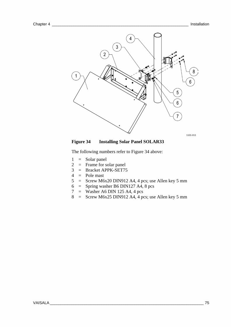
Chapter 4 _______________________________________________________________ Installation
VAISALA _______________________________________________________________________ 75
1101-011
Figure 34 Installing Solar Panel SOLAR33
The following numbers refer to Figure 34 above:
1 = Solar panel 2 = Frame for solar panel 3 = Bracket APPK-SET75 4 = Pole mast 5 = Screw M6x20 DIN912 A4, 4 pcs; use Allen key 5 mm 6 = Spring washer B6 DIN127 A4, 8 pcs 7 = Washer A6 DIN 125 A4, 4 pcs 8 = Screw M6x25 DIN912 A4, 4 pcs; use Allen key 5 mm
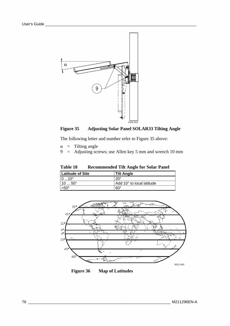
User's Guide ______________________________________________________________________
76 __________________________________________________________________ M211296EN-A
1101-012
Figure 35 Adjusting Solar Panel SOLAR33 Tilting Angle
The following letter and number refer to Figure 35 above:
α = Tilting angle 9 = Adjusting screws; use Allen key 5 mm and wrench 10 mm
Table 18 Recommended Tilt Angle for Solar Panel Latitude of Site Tilt Angle 0 ...10° 20° 10 ... 50° Add 10° to local latitude >50° 60°
0011-042
Figure 36 Map of Latitudes
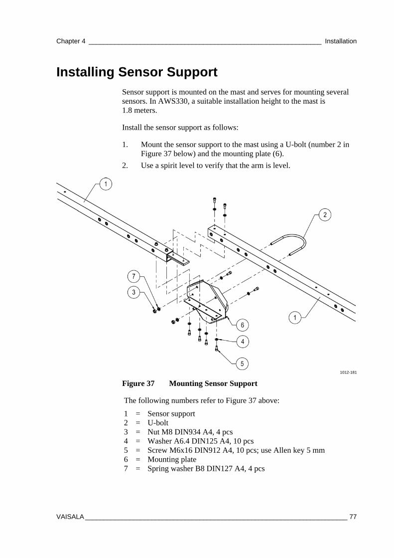
Chapter 4 _______________________________________________________________ Installation
VAISALA _______________________________________________________________________ 77
Installing Sensor Support Sensor support is mounted on the mast and serves for mounting several sensors. In AWS330, a suitable installation height to the mast is 1.8 meters.
Install the sensor support as follows:
1. Mount the sensor support to the mast using a U-bolt (number 2 in Figure 37 below) and the mounting plate (6).
2. Use a spirit level to verify that the arm is level.
1012-181
Figure 37 Mounting Sensor Support
The following numbers refer to Figure 37 above:
1 = Sensor support 2 = U-bolt 3 = Nut M8 DIN934 A4, 4 pcs 4 = Washer A6.4 DIN125 A4, 10 pcs 5 = Screw M6x16 DIN912 A4, 10 pcs; use Allen key 5 mm 6 = Mounting plate 7 = Spring washer B8 DIN127 A4, 4 pcs
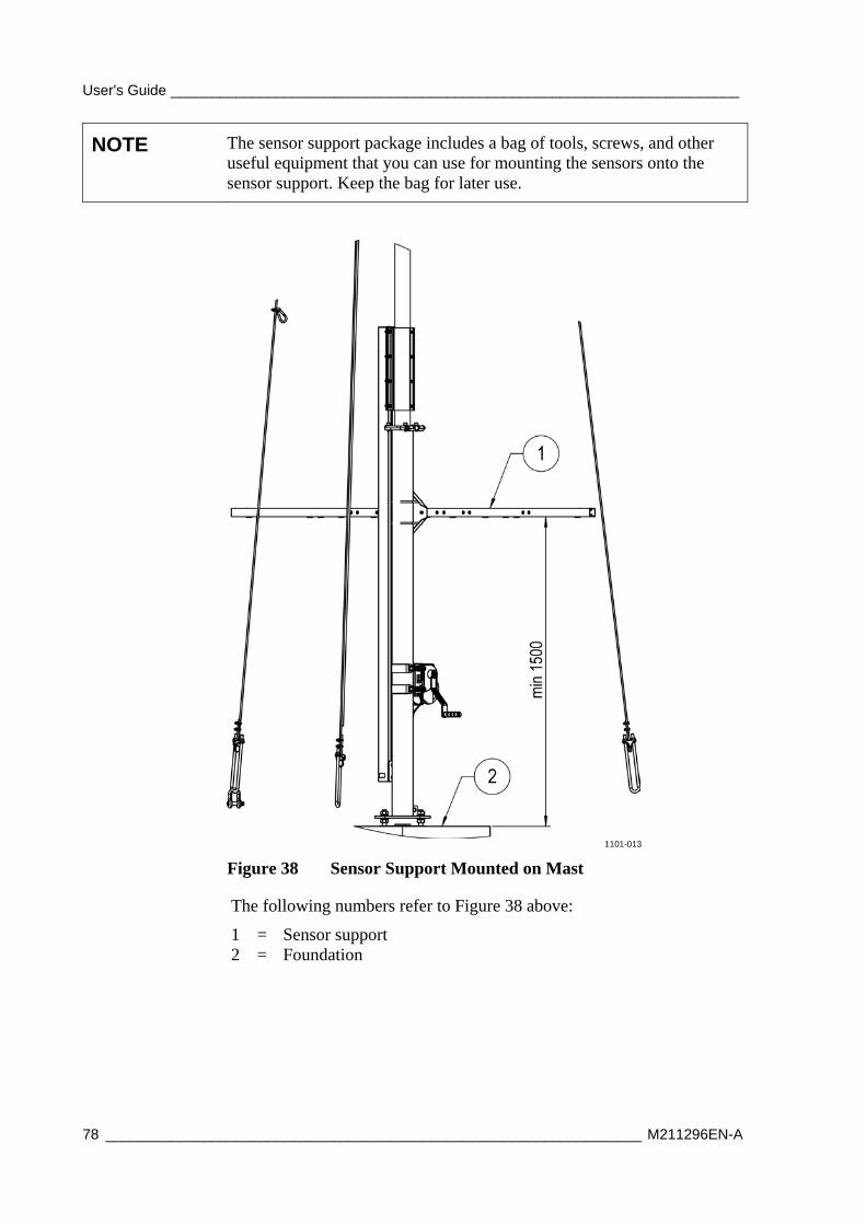
User's Guide ______________________________________________________________________
78 __________________________________________________________________ M211296EN-A
NOTE The sensor support package includes a bag of tools, screws, and other useful equipment that you can use for mounting the sensors onto the sensor support. Keep the bag for later use.
1101-013
Figure 38 Sensor Support Mounted on Mast
The following numbers refer to Figure 38 above:
1 = Sensor support 2 = Foundation
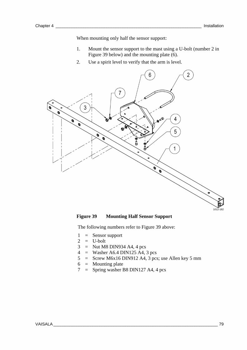
Chapter 4 _______________________________________________________________ Installation
VAISALA _______________________________________________________________________ 79
When mounting only half the sensor support:
1. Mount the sensor support to the mast using a U-bolt (number 2 in Figure 39 below) and the mounting plate (6).
2. Use a spirit level to verify that the arm is level.
1012-182
Figure 39 Mounting Half Sensor Support
The following numbers refer to Figure 39 above:
1 = Sensor support 2 = U-bolt 3 = Nut M8 DIN934 A4, 4 pcs 4 = Washer A6.4 DIN125 A4, 3 pcs 5 = Screw M6x16 DIN912 A4, 3 pcs; use Allen key 5 mm 6 = Mounting plate 7 = Spring washer B8 DIN127 A4, 4 pcs
User's Guide ______________________________________________________________________
80 __________________________________________________________________ M211296EN-A
Installing Air Temperature and Relative Humidity Probe HMP155
It is recommended that you install the HMP155 probe and Radiation Shield DTR503A onto a sensor support for WMO-compliant measurement results.
NOTE The radiation shield is important in protecting the sensor from direct sunlight, and must always be used.
1. Install the radiation shield DTR503A (number 2 in Figure 40 on page 81) onto the sensor support.
2. Remove the protecting cover from the HMP155 probe. Loosen the fastening ring of the sensor with your fingers and put the sensor inside the radiation shield. Tighten the fastening ring without using excessive force.
3. Lead the sensor cable along the sensor support and attach it with cable ties.
4. Connect the sensor cable to the Temp. / Hum. connector on the bottom of the enclosure; see section Connecting Sensor Cables on page 97.
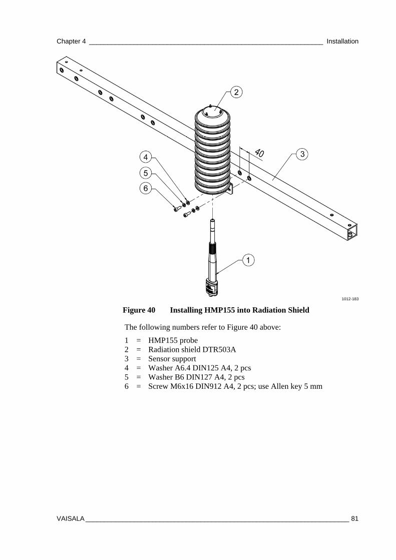
Chapter 4 _______________________________________________________________ Installation
VAISALA _______________________________________________________________________ 81
1012-183
Figure 40 Installing HMP155 into Radiation Shield
The following numbers refer to Figure 40 above:
1 = HMP155 probe 2 = Radiation shield DTR503A 3 = Sensor support 4 = Washer A6.4 DIN125 A4, 2 pcs 5 = Washer B6 DIN127 A4, 2 pcs 6 = Screw M6x16 DIN912 A4, 2 pcs; use Allen key 5 mm
User's Guide ______________________________________________________________________
82 __________________________________________________________________ M211296EN-A
Installing Pyranometer CMP6 Pyranometer CMP6 is installed on a mounting plate for thermal isolation.
1. Install the mounting plate (number 2 in Figure 41 on page 83) onto the sensor support (1).
2. Prepare the sensor (3):
a. Carefully remove the plastic cover of the sensor by pressing the clips on the cover.
b. Attach the cable to the sensor and push the plastic cover back into place.
NOTE Be careful not to drop the sensor when you remove the cover. The cover is attached tightly.
3. Attach the sensor onto the mounting plate1) on the sensor support. Place the pyranometer on the mounting plate so that the leveling screws (8) and the leg set in the small drillings on the mounting plate. Two long screws (6) and two nylon insulators (7) are provided for fixing the sensor on the mounting plate. The pyranometer should first be secured lightly with the screws to allow leveling.
4. Level the sensor by turning the leveling screws (8). Use the screw nearest to the spirit level first. When the sensor is straight according to the spirit level, the thermopile is horizontal within 0.05 °. This causes a maximum azimuthal variation of ±0.5% at a solar elevation of 10 °.
NOTE Correct leveling of the sensor is essential for obtaining accurate measurements. Use the spirit level on the CMP6 to level the sensor.
5. Secure the pyranometer tightly with the two screws (6). Ensure that the pyranometer maintains its leveled position.
6. Route the sensor cable along the sensor support and secure it with cable ties.
7. Connect the sensor cable to the Sol. Rad. connector on the bottom of the enclosure; see section Connecting Sensor Cables on page 97.
1) Temperature fluctuations of the pyranometer body can produce offset signals. Thus, the sensor is thermally isolated from its fixtures using non-conducting materials.
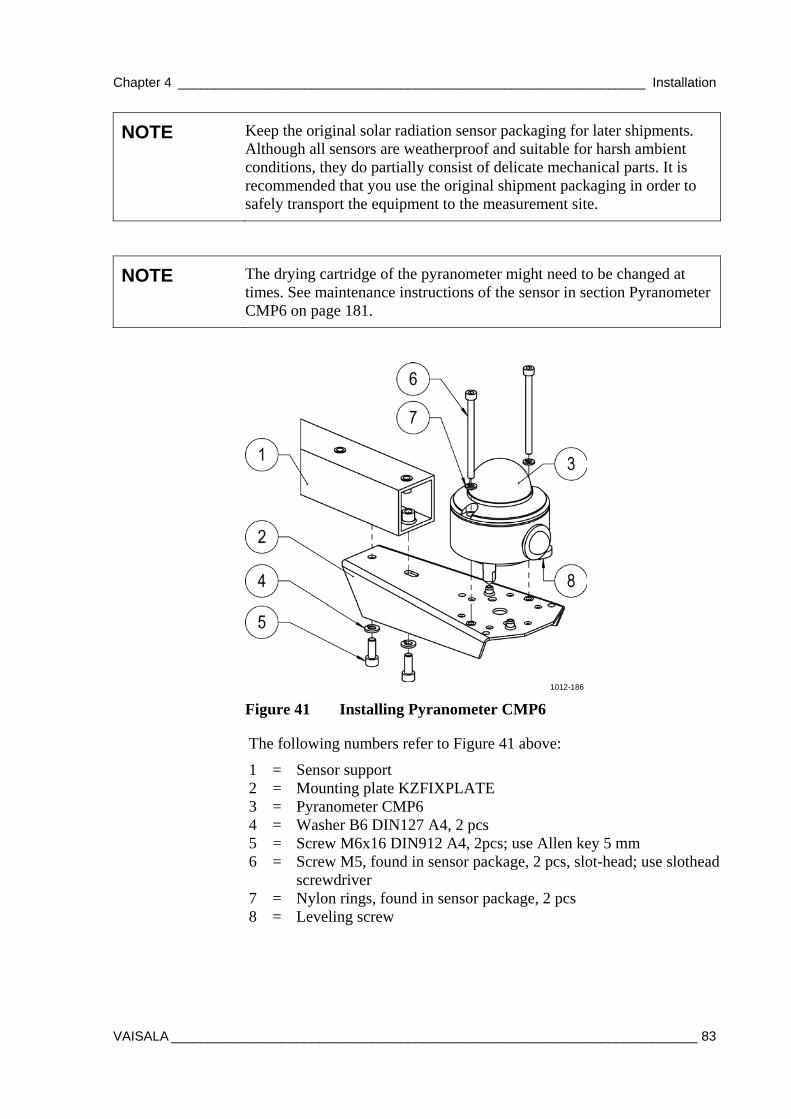
Chapter 4 _______________________________________________________________ Installation
VAISALA _______________________________________________________________________ 83
NOTE Keep the original solar radiation sensor packaging for later shipments. Although all sensors are weatherproof and suitable for harsh ambient conditions, they do partially consist of delicate mechanical parts. It is recommended that you use the original shipment packaging in order to safely transport the equipment to the measurement site.
NOTE The drying cartridge of the pyranometer might need to be changed at times. See maintenance instructions of the sensor in section Pyranometer CMP6 on page 181.
1012-186
Figure 41 Installing Pyranometer CMP6
The following numbers refer to Figure 41 above:
1 = Sensor support 2 = Mounting plate KZFIXPLATE 3 = Pyranometer CMP6 4 = Washer B6 DIN127 A4, 2 pcs 5 = Screw M6x16 DIN912 A4, 2pcs; use Allen key 5 mm 6 = Screw M5, found in sensor package, 2 pcs, slot-head; use slothead
screwdriver 7 = Nylon rings, found in sensor package, 2 pcs 8 = Leveling screw
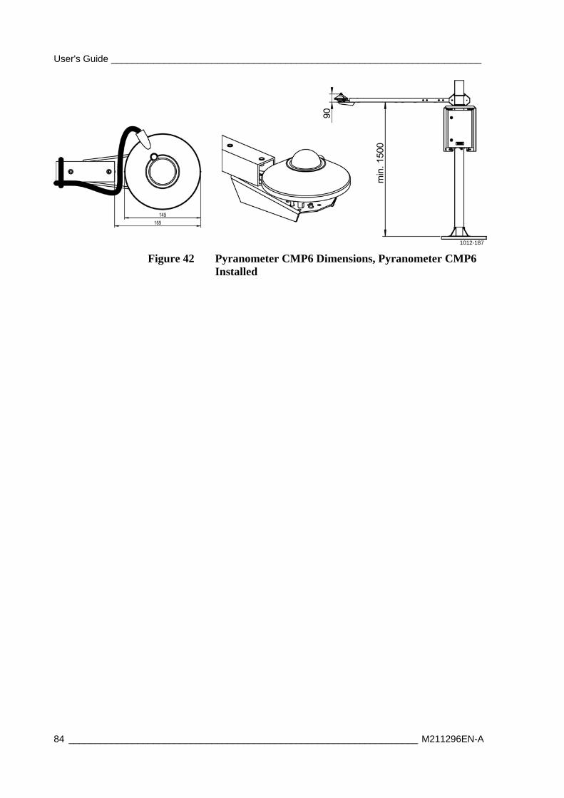
User's Guide ______________________________________________________________________
84 __________________________________________________________________ M211296EN-A
1012-187
Figure 42 Pyranometer CMP6 Dimensions, Pyranometer CMP6 Installed
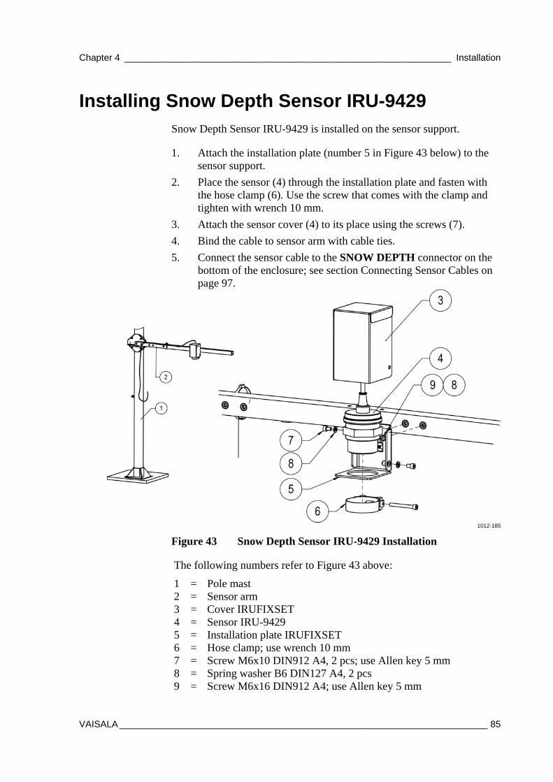
Chapter 4 _______________________________________________________________ Installation
VAISALA _______________________________________________________________________ 85
Installing Snow Depth Sensor IRU-9429 Snow Depth Sensor IRU-9429 is installed on the sensor support.
1. Attach the installation plate (number 5 in Figure 43 below) to the sensor support.
2. Place the sensor (4) through the installation plate and fasten with the hose clamp (6). Use the screw that comes with the clamp and tighten with wrench 10 mm.
3. Attach the sensor cover (4) to its place using the screws (7).
4. Bind the cable to sensor arm with cable ties.
5. Connect the sensor cable to the SNOW DEPTH connector on the bottom of the enclosure; see section Connecting Sensor Cables on page 97.
1012-185
Figure 43 Snow Depth Sensor IRU-9429 Installation
The following numbers refer to Figure 43 above:
1 = Pole mast 2 = Sensor arm 3 = Cover IRUFIXSET 4 = Sensor IRU-9429 5 = Installation plate IRUFIXSET 6 = Hose clamp; use wrench 10 mm 7 = Screw M6x10 DIN912 A4, 2 pcs; use Allen key 5 mm 8 = Spring washer B6 DIN127 A4, 2 pcs 9 = Screw M6x16 DIN912 A4; use Allen key 5 mm

User's Guide ______________________________________________________________________
86 __________________________________________________________________ M211296EN-A
Installing Soil Temperature Sensor QMT110 Vaisala Soil Temperature Probe QMT110 is used for precision measurement of ground and soil temperatures. In AWS330, you can have up to two QMT110 sensors.
1. Choose a desired location for the sensor. Measurement site should be undisturbed ground, 1 m², and typical of the surface of interest. The ground surface should be level with respect to the immediate (10 m radius) area.
2. Make a hole with a shovel to a depth slightly deeper than the desired installation depth of the sensor.
3. To have good sensor contact with the soil, push the sensor into the wall of the hole horizontally until set firmly.
4. Fill the hole with the dug-up soil.
5. Connect the sensor cable to the Soil T1 connector on the bottom of the enclosure. For two QMT110 sensors, use the Soil T2 connector as well; see section Connecting Sensor Cables on page 97.
1012-188
Figure 44 Installing Soil Temperature Sensor QMT110
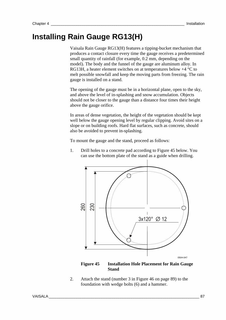
Chapter 4 _______________________________________________________________ Installation
VAISALA _______________________________________________________________________ 87
Installing Rain Gauge RG13(H) Vaisala Rain Gauge RG13(H) features a tipping-bucket mechanism that produces a contact closure every time the gauge receives a predetermined small quantity of rainfall (for example, 0.2 mm, depending on the model). The body and the funnel of the gauge are aluminum alloy. In RG13H, a heater element switches on at temperatures below +4 °C to melt possible snowfall and keep the moving parts from freezing. The rain gauge is installed on a stand.
The opening of the gauge must be in a horizontal plane, open to the sky, and above the level of in-splashing and snow accumulation. Objects should not be closer to the gauge than a distance four times their height above the gauge orifice.
In areas of dense vegetation, the height of the vegetation should be kept well below the gauge opening level by regular clipping. Avoid sites on a slope or on building roofs. Hard flat surfaces, such as concrete, should also be avoided to prevent in-splashing.
To mount the gauge and the stand, proceed as follows:
1. Drill holes to a concrete pad according to Figure 45 below. You can use the bottom plate of the stand as a guide when drilling.
0504-047
Figure 45 Installation Hole Placement for Rain Gauge Stand
2. Attach the stand (number 3 in Figure 46 on page 89) to the foundation with wedge bolts (6) and a hammer.
User's Guide ______________________________________________________________________
88 __________________________________________________________________ M211296EN-A
3. Place the base of the rain gauge (9) onto the stand and level it with the three leveling screws (2). Use the spirit level (13) on the rain gauge for the leveling. Finally, secure the locknuts (12).
NOTE Use the spirit level on the RG13(H) for the leveling (number 3 in Figure 46 on page 89).
4. Secure the base through the two holding lugs (14) with the provided Allen bolts, washers, and nuts (7, 8, and 10).
5. Carefully remove the rubber band (11), which is fitted for transit purposes, and check that the bucket pivots easily.
NOTE Remember to remove the rubber band from inside the RG13(H) (number 11 in Figure 46 on page 89).
6. Attach the outer tube of the rain gauge (1) onto the base and secure it with the locks.
7. Route the signal/power along the stand and secure it with cable ties (15 and 16).
8. Connect the signal/power cable to the Rain connector on the bottom of the enclosure; see section Connecting Sensor Cables on page 97.
The following numbers refer to Figure 46 on page 89:
1 = Outer tube of Rain Gauge RG13 2 = Leveling screw 3 = Pedestal 4 = Nut M10 DIN934 A4, 4 pcs; use wrench 17 mm 5 = Washer A10 DIN125 A4, 4 pcs 6 = Wedge bolts; use a hammer 7 = Allen bolt M8x30 DIN912 A4, 2 pcs; Allen key 6 mm 8 = Washer A8 DIN125 A4, 2 pcs 9 = Base of Rain Gauge RG13 10 = Nut M8 DIN985 A4, 2 pcs; use wrench 13 mm 11 = Rubber band 12 = Locknut 13 = Spirit level 14 = Holding lugs, 2 pcs 15 = Cable 16 = Cable tie
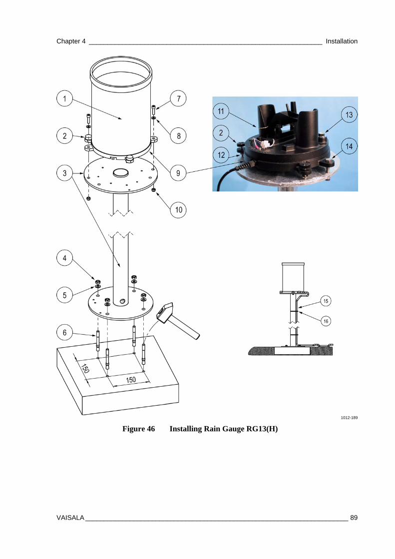
Chapter 4 _______________________________________________________________ Installation
VAISALA _______________________________________________________________________ 89
1012-189
Figure 46 Installing Rain Gauge RG13(H)
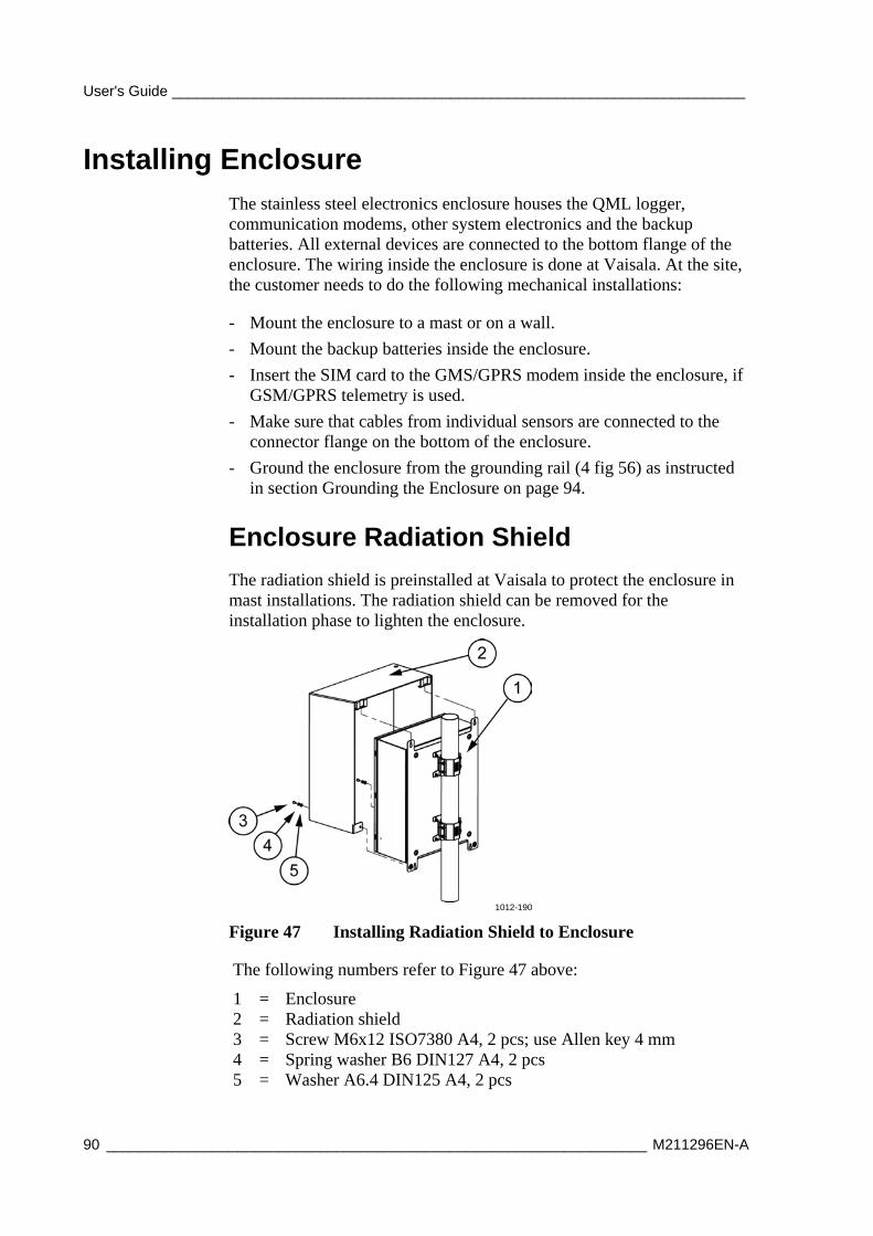
User's Guide ______________________________________________________________________
90 __________________________________________________________________ M211296EN-A
Installing Enclosure The stainless steel electronics enclosure houses the QML logger, communication modems, other system electronics and the backup batteries. All external devices are connected to the bottom flange of the enclosure. The wiring inside the enclosure is done at Vaisala. At the site, the customer needs to do the following mechanical installations:
- Mount the enclosure to a mast or on a wall.
- Mount the backup batteries inside the enclosure.
- Insert the SIM card to the GMS/GPRS modem inside the enclosure, if GSM/GPRS telemetry is used.
- Make sure that cables from individual sensors are connected to the connector flange on the bottom of the enclosure.
- Ground the enclosure from the grounding rail (4 fig 56) as instructed in section Grounding the Enclosure on page 94.
Enclosure Radiation Shield
The radiation shield is preinstalled at Vaisala to protect the enclosure in mast installations. The radiation shield can be removed for the installation phase to lighten the enclosure.
1012-190
Figure 47 Installing Radiation Shield to Enclosure
The following numbers refer to Figure 47 above:
1 = Enclosure 2 = Radiation shield 3 = Screw M6x12 ISO7380 A4, 2 pcs; use Allen key 4 mm 4 = Spring washer B6 DIN127 A4, 2 pcs 5 = Washer A6.4 DIN125 A4, 2 pcs
Chapter 4 _______________________________________________________________ Installation
VAISALA _______________________________________________________________________ 91
Installing Enclosure to the Mast
In a mast installation, the enclosure is mounted below the sensor support. The bottom of the enclosure comes roughly 1 m from the ground. Mast mounting sets (number 7 in Figure 48 on page 92) are used for the installation, and the enclosure door should face north (in the northern hemisphere) to avoid solar radiation heating the enclosure.
1. Install the mast mounting sets. Tighten the sets lightly.
2. Screw the two uppermost screws and washers to the enclosure. Do this for both mounting sets. Leave the screws out by about 10 mm.
3. Lift the enclosure to the upper mast mounting set so that the screws slide to the mounting set slots (1).
4. Slide the lower mounting set to fit the lower screws of the enclosure. Tighten the screws (5) and install rest of the mounting set screws.
5. Loose the mounting sets and slide the enclosure to the desired height (roughly 1 m from the ground to the bottom of the enclosure). Make sure that the enclosure door is toward north. Tighten all screws.
6. If you have removed the radiation shield before installation, attach it again to the enclosure; see section Enclosure Radiation Shield on page 90.
Alternative Installation Procedure (More than One Person Available)
1. Screw the two front-most halves of the mounting set (7) using screws and washers (5, 6) firmly to the enclosure. Do this for both mounting sets.
2. Lift the enclosure and press the open mounting set halves firmly to the mast.
3. Attach the remaining mounting set halves to the open halves using the screws and washers (4, 3).
4. If you have removed the radiation shield before installation, attach it again to the enclosure; see section Enclosure Radiation Shield on page 90.
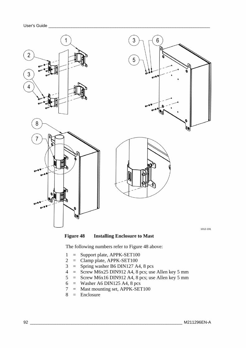
User's Guide ______________________________________________________________________
92 __________________________________________________________________ M211296EN-A
1012-191
Figure 48 Installing Enclosure to Mast
The following numbers refer to Figure 48 above:
1 = Support plate, APPK-SET100 2 = Clamp plate, APPK-SET100 3 = Spring washer B6 DIN127 A4, 8 pcs 4 = Screw M6x25 DIN912 A4, 8 pcs; use Allen key 5 mm 5 = Screw M6x16 DIN912 A4, 8 pcs; use Allen key 5 mm 6 = Washer A6 DIN125 A4, 8 pcs 7 = Mast mounting set, APPK-SET100 8 = Enclosure
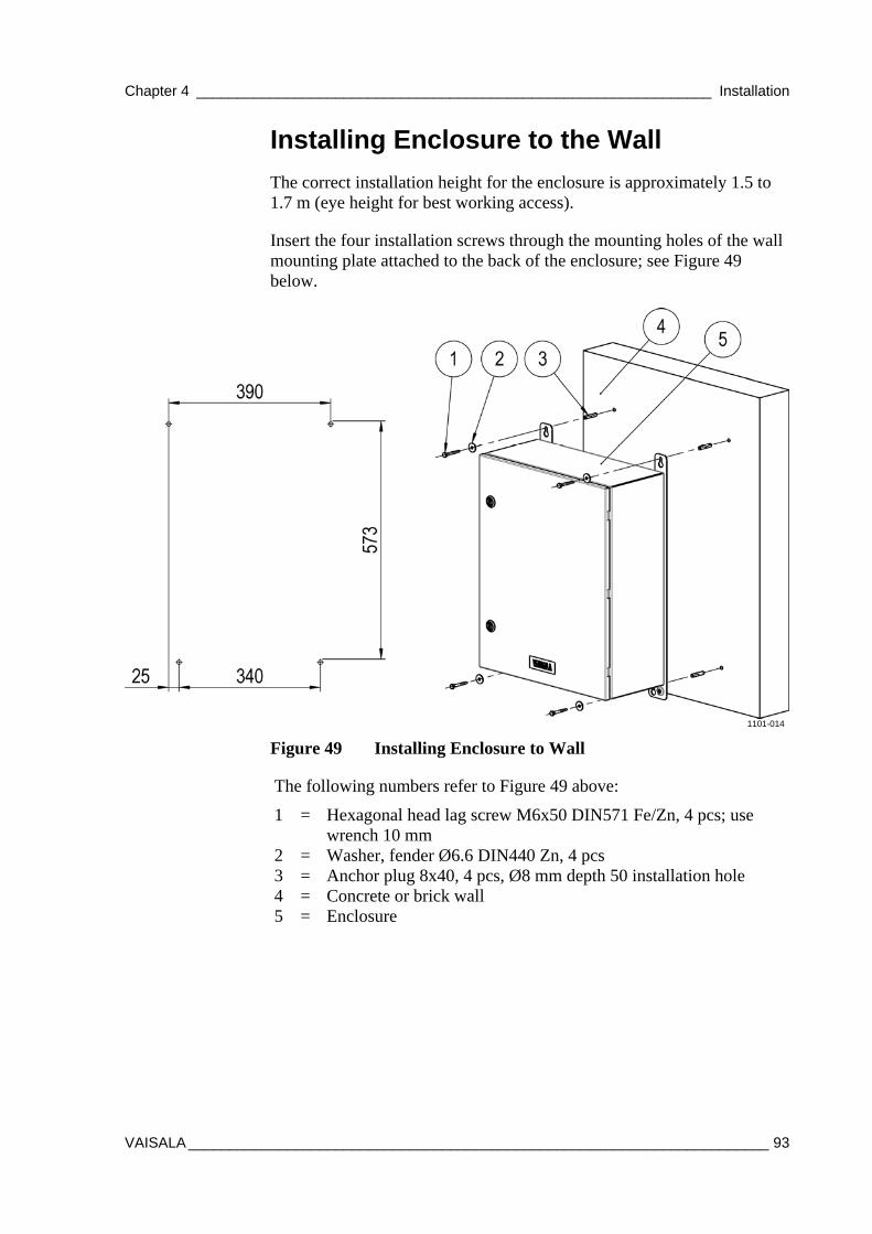
Chapter 4 _______________________________________________________________ Installation
VAISALA _______________________________________________________________________ 93
Installing Enclosure to the Wall
The correct installation height for the enclosure is approximately 1.5 to 1.7 m (eye height for best working access).
Insert the four installation screws through the mounting holes of the wall mounting plate attached to the back of the enclosure; see Figure 49 below.
1101-014
Figure 49 Installing Enclosure to Wall
The following numbers refer to Figure 49 above:
1 = Hexagonal head lag screw M6x50 DIN571 Fe/Zn, 4 pcs; use wrench 10 mm
2 = Washer, fender Ø6.6 DIN440 Zn, 4 pcs 3 = Anchor plug 8x40, 4 pcs, Ø8 mm depth 50 installation hole 4 = Concrete or brick wall 5 = Enclosure
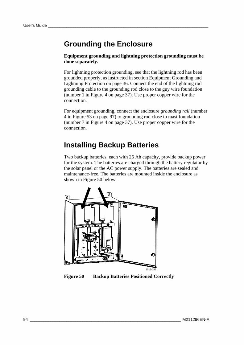
User's Guide ______________________________________________________________________
94 __________________________________________________________________ M211296EN-A
Grounding the Enclosure
Equipment grounding and lightning protection grounding must be done separately.
For lightning protection grounding, see that the lightning rod has been grounded properly, as instructed in section Equipment Grounding and Lightning Protection on page 36. Connect the end of the lightning rod grounding cable to the grounding rod close to the guy wire foundation (number 1 in Figure 4 on page 37). Use proper copper wire for the connection.
For equipment grounding, connect the enclosure grounding rail (number 4 in Figure 53 on page 97) to grounding rod close to mast foundation (number 7 in Figure 4 on page 37). Use proper copper wire for the connection.
Installing Backup Batteries
Two backup batteries, each with 26 Ah capacity, provide backup power for the system. The batteries are charged through the battery regulator by the solar panel or the AC power supply. The batteries are sealed and maintenance-free. The batteries are mounted inside the enclosure as shown in Figure 50 below.
1012-192
Figure 50 Backup Batteries Positioned Correctly
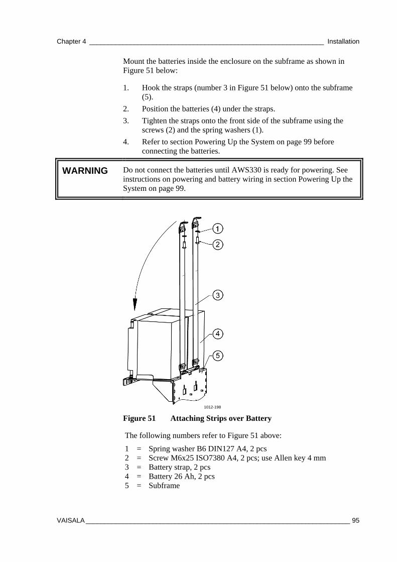
Chapter 4 _______________________________________________________________ Installation
VAISALA _______________________________________________________________________ 95
Mount the batteries inside the enclosure on the subframe as shown in Figure 51 below:
1. Hook the straps (number 3 in Figure 51 below) onto the subframe (5).
2. Position the batteries (4) under the straps.
3. Tighten the straps onto the front side of the subframe using the screws (2) and the spring washers (1).
4. Refer to section Powering Up the System on page 99 before connecting the batteries.
WARNING Do not connect the batteries until AWS330 is ready for powering. See instructions on powering and battery wiring in section Powering Up the System on page 99.
1012-198
Figure 51 Attaching Strips over Battery
The following numbers refer to Figure 51 above:
1 = Spring washer B6 DIN127 A4, 2 pcs 2 = Screw M6x25 ISO7380 A4, 2 pcs; use Allen key 4 mm 3 = Battery strap, 2 pcs 4 = Battery 26 Ah, 2 pcs 5 = Subframe
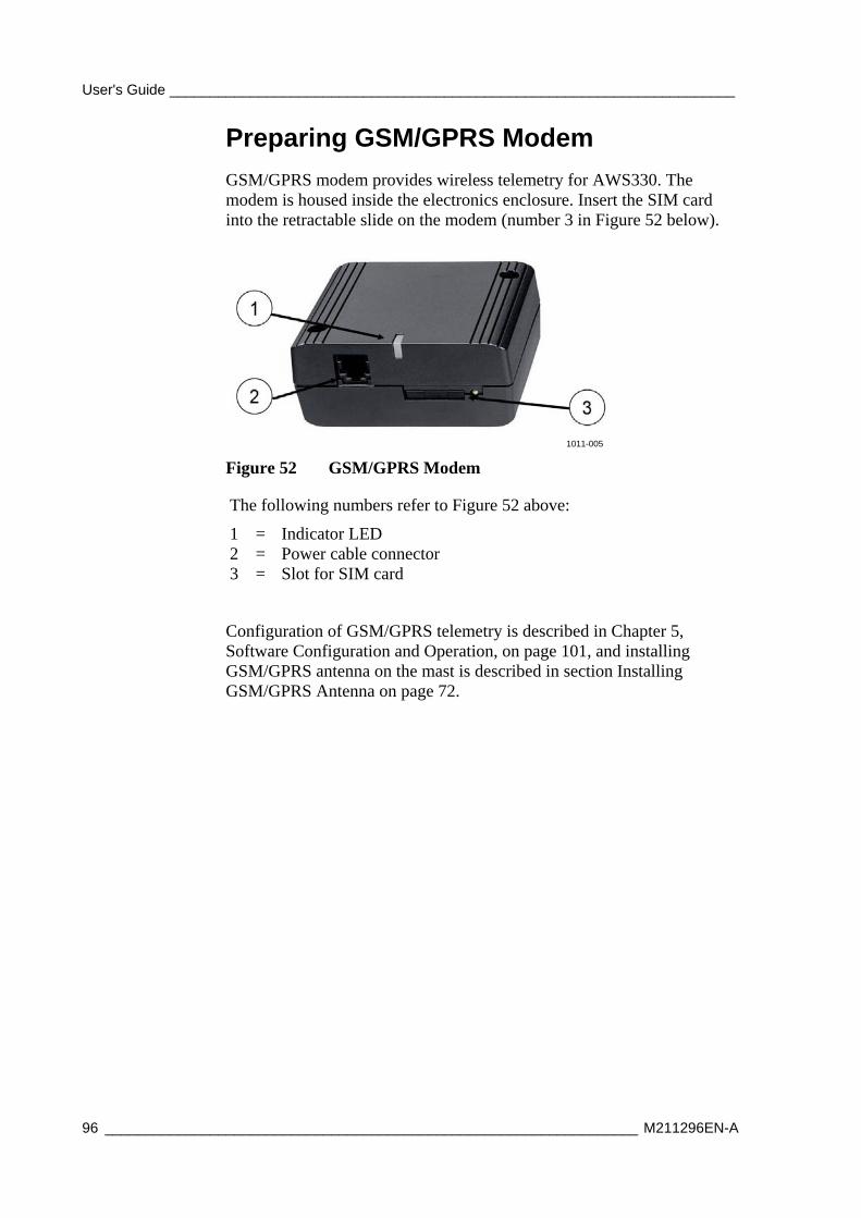
User's Guide ______________________________________________________________________
96 __________________________________________________________________ M211296EN-A
Preparing GSM/GPRS Modem
GSM/GPRS modem provides wireless telemetry for AWS330. The modem is housed inside the electronics enclosure. Insert the SIM card into the retractable slide on the modem (number 3 in Figure 52 below).
1011-005
Figure 52 GSM/GPRS Modem
The following numbers refer to Figure 52 above:
1 = Indicator LED 2 = Power cable connector 3 = Slot for SIM card
Configuration of GSM/GPRS telemetry is described in Chapter 5, Software Configuration and Operation, on page 101, and installing GSM/GPRS antenna on the mast is described in section Installing GSM/GPRS Antenna on page 72.
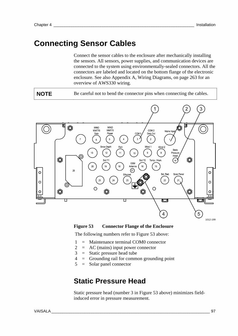
Chapter 4 _______________________________________________________________ Installation
VAISALA _______________________________________________________________________ 97
Connecting Sensor Cables Connect the sensor cables to the enclosure after mechanically installing the sensors. All sensors, power supplies, and communication devices are connected to the system using environmentally-sealed connectors. All the connectors are labeled and located on the bottom flange of the electronic enclosure. See also Appendix A, Wiring Diagrams, on page 263 for an overview of AWS330 wiring.
NOTE Be careful not to bend the connector pins when connecting the cables.
1012-199
Figure 53 Connector Flange of the Enclosure
The following numbers refer to Figure 53 above:
1 = Maintenance terminal COM0 connector 2 = AC (mains) input power connector 3 = Static pressure head tube 4 = Grounding rail for common grounding point 5 = Solar panel connector
Static Pressure Head
Static pressure head (number 3 in Figure 53 above) minimizes field-induced error in pressure measurement.
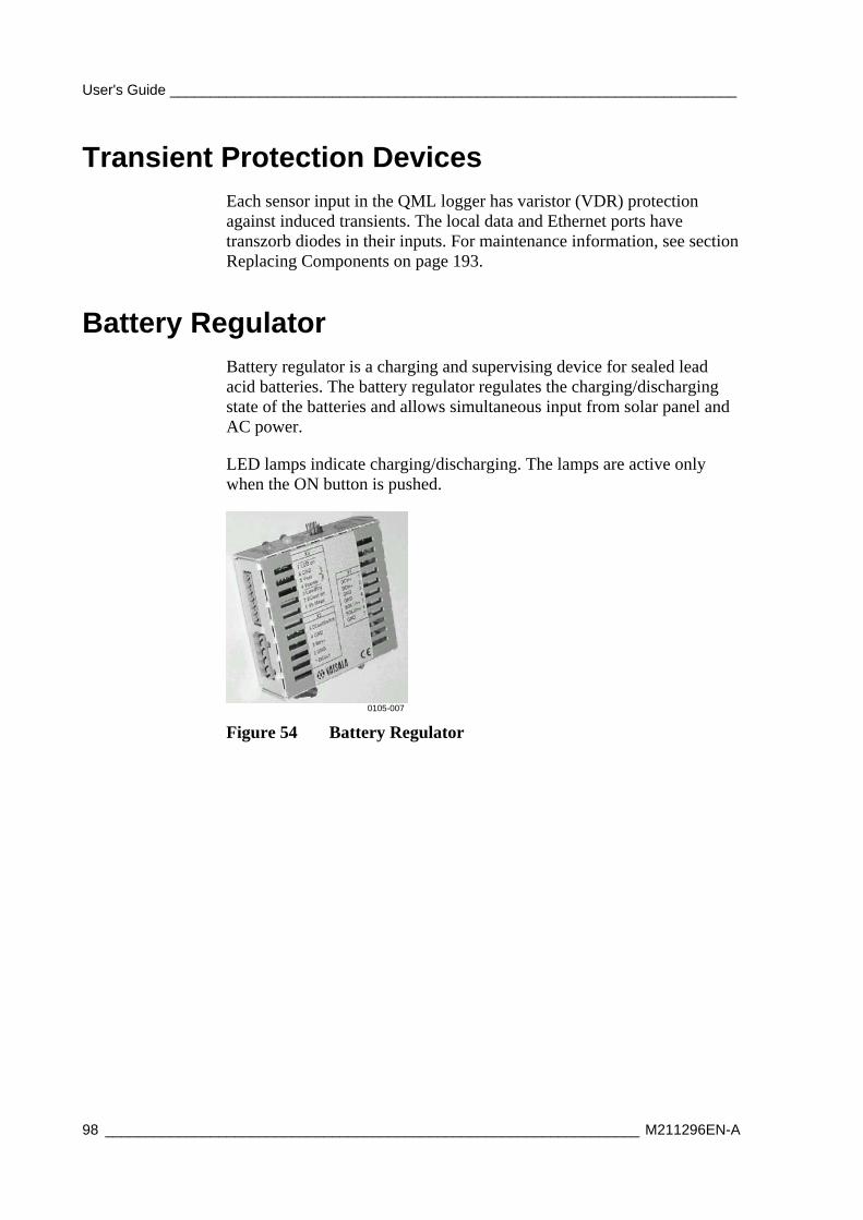
User's Guide ______________________________________________________________________
98 __________________________________________________________________ M211296EN-A
Transient Protection Devices Each sensor input in the QML logger has varistor (VDR) protection against induced transients. The local data and Ethernet ports have transzorb diodes in their inputs. For maintenance information, see section Replacing Components on page 193.
Battery Regulator Battery regulator is a charging and supervising device for sealed lead acid batteries. The battery regulator regulates the charging/discharging state of the batteries and allows simultaneous input from solar panel and AC power.
LED lamps indicate charging/discharging. The lamps are active only when the ON button is pushed.
0105-007
Figure 54 Battery Regulator
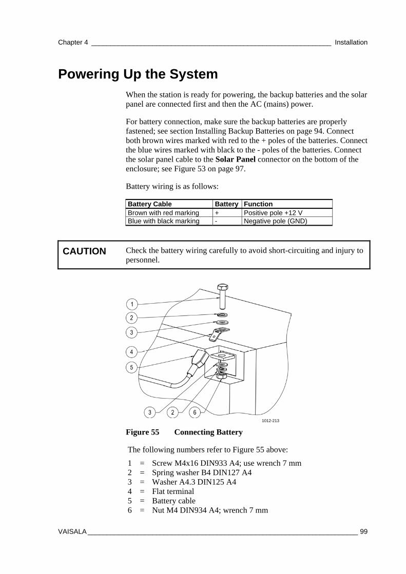
Chapter 4 _______________________________________________________________ Installation
VAISALA _______________________________________________________________________ 99
Powering Up the System When the station is ready for powering, the backup batteries and the solar panel are connected first and then the AC (mains) power.
For battery connection, make sure the backup batteries are properly fastened; see section Installing Backup Batteries on page 94. Connect both brown wires marked with red to the + poles of the batteries. Connect the blue wires marked with black to the - poles of the batteries. Connect the solar panel cable to the Solar Panel connector on the bottom of the enclosure; see Figure 53 on page 97.
Battery wiring is as follows:
Battery Cable Battery Function Brown with red marking + Positive pole +12 V Blue with black marking - Negative pole (GND)
CAUTION Check the battery wiring carefully to avoid short-circuiting and injury to personnel.
1012-213
Figure 55 Connecting Battery
The following numbers refer to Figure 55 above:
1 = Screw M4x16 DIN933 A4; use wrench 7 mm 2 = Spring washer B4 DIN127 A4 3 = Washer A4.3 DIN125 A4 4 = Flat terminal 5 = Battery cable 6 = Nut M4 DIN934 A4; wrench 7 mm

User's Guide ______________________________________________________________________
100 _________________________________________________________________ M211296EN-A
For AC (mains) powering, make sure the site has been prepared according the instructions in section Site Preparation on page 35. Before connecting the AC (mains) power cable, ensure there is no power connected to the cable (by turning down the fuse or turning off the power switch). Connect the AC (mains) power cable to the Mains Input connector on bottom of the enclosure; see Figure 53 on page 97. Turn on the AC power.

Chapter 5 __________________________________________ Software Configuration and Operation
VAISALA ______________________________________________________________________ 101
CHAPTER 5
SOFTWARE CONFIGURATION AND OPERATION
This chapter contains information on operating AWS Client software and introduces optional Local Display QMD202.
AWS Client is used for working with the QML logger, for example, for setting station-specific parameters to the setup file and for downloading the log files.
Software Installation To operate AWS Client software, you need a PC with Windows® operating system.
Install AWS Client as follows:
1. Insert the AWS Client installation CD-ROM disc into your computer's CD drive and run the file setup.exe.
2. The setup wizard will guide you during the installation process. Follow the instructions of the wizard to complete the setup.

User's Guide ______________________________________________________________________
102 _________________________________________________________________ M211296EN-A
Connecting AWS Client to AWS330
Installing USB Driver
If you are using a computer that does not have a RS232 serial port, such as most laptops, a USB to RS232 converter cable is provided for using a local connection to the AWS330 system. Install the driver for the cable as follows:
1. Insert Vaisala USB Instrument Driver CD to CD/DVD drive of your PC.
2. If the installation program is not started automatically, start it from the CD root directory, program setup.exe.
3. Follow the instructions given by the installation program.
4. When the driver installation is complete, connect the USB cable to a free slot on your PC. Allow the operating system to detect the driver for the cable automatically.
5. To check which port has been assigned for the USB serial port, launch program Vaisala USB Instrument Finder from the Start menu.
1012-209
Figure 56 Finding Port Number for USB Serial Port
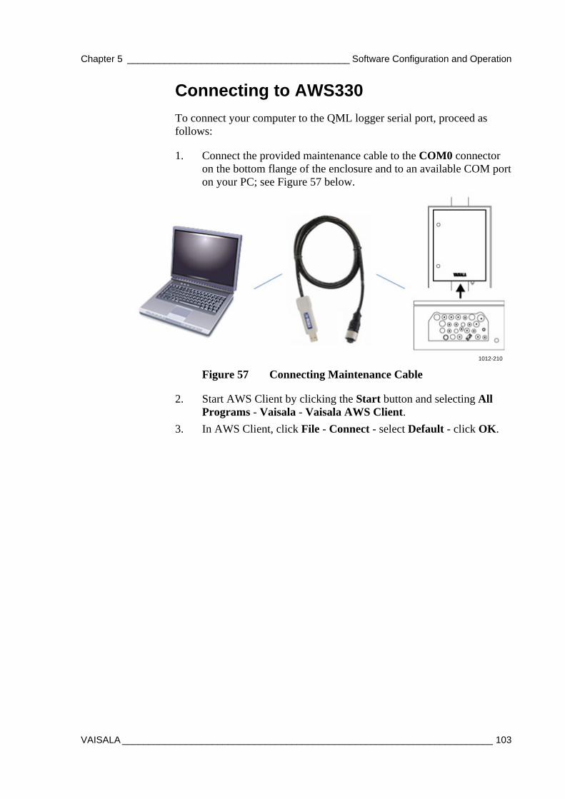
Chapter 5 __________________________________________ Software Configuration and Operation
VAISALA ______________________________________________________________________ 103
Connecting to AWS330
To connect your computer to the QML logger serial port, proceed as follows:
1. Connect the provided maintenance cable to the COM0 connector on the bottom flange of the enclosure and to an available COM port on your PC; see Figure 57 below.
1012-210
Figure 57 Connecting Maintenance Cable
2. Start AWS Client by clicking the Start button and selecting All Programs - Vaisala - Vaisala AWS Client.
3. In AWS Client, click File - Connect - select Default - click OK.
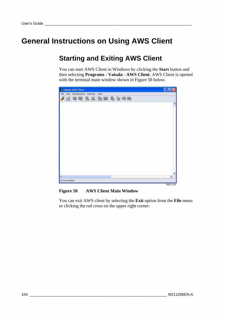
User's Guide ______________________________________________________________________
104 _________________________________________________________________ M211296EN-A
General Instructions on Using AWS Client
Starting and Exiting AWS Client
You can start AWS Client in Windows by clicking the Start button and then selecting Programs - Vaisala - AWS Client. AWS Client is opened with the terminal main window shown in Figure 58 below.
0802-134
Figure 58 AWS Client Main Window
You can exit AWS client by selecting the Exit option from the File menu or clicking the red cross on the upper right corner.
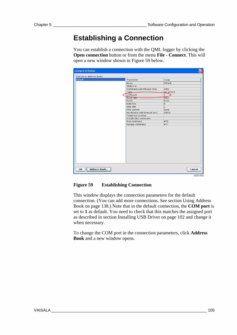
Chapter 5 __________________________________________ Software Configuration and Operation
VAISALA ______________________________________________________________________ 105
Establishing a Connection
You can establish a connection with the QML logger by clicking the Open connection button or from the menu File - Connect. This will open a new window shown in Figure 59 below.
1101-015
Figure 59 Establishing Connection
This window displays the connection parameters for the default connection. (You can add more connections. See section Using Address Book on page 138.) Note that in the default connection, the COM port is set to 1 as default. You need to check that this matches the assigned port as described in section Installing USB Driver on page 102 and change it when necessary.
To change the COM port in the connection parameters, click Address Book and a new window opens.
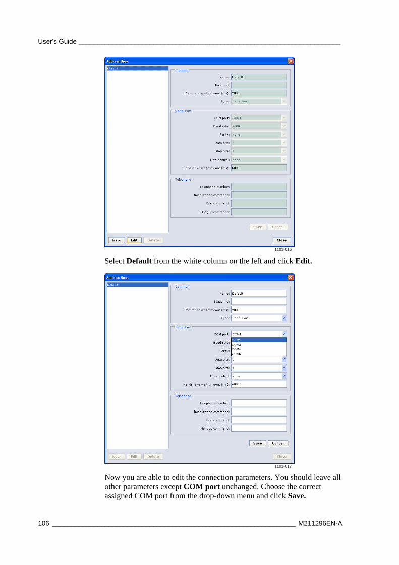
User's Guide ______________________________________________________________________
106 _________________________________________________________________ M211296EN-A
1101-016
Select Default from the white column on the left and click Edit.
1101-017
Now you are able to edit the connection parameters. You should leave all other parameters except COM port unchanged. Choose the correct assigned COM port from the drop-down menu and click Save.
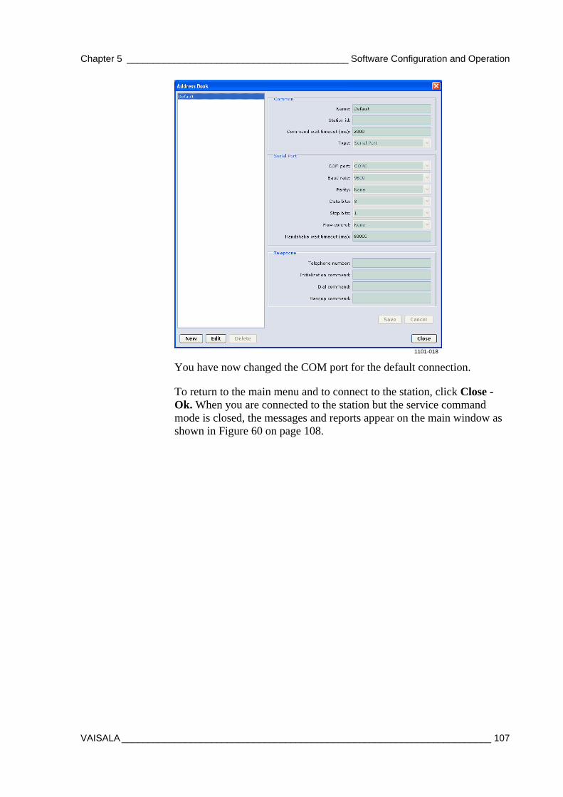
Chapter 5 __________________________________________ Software Configuration and Operation
VAISALA ______________________________________________________________________ 107
1101-018
You have now changed the COM port for the default connection.
To return to the main menu and to connect to the station, click Close - Ok. When you are connected to the station but the service command mode is closed, the messages and reports appear on the main window as shown in Figure 60 on page 108.
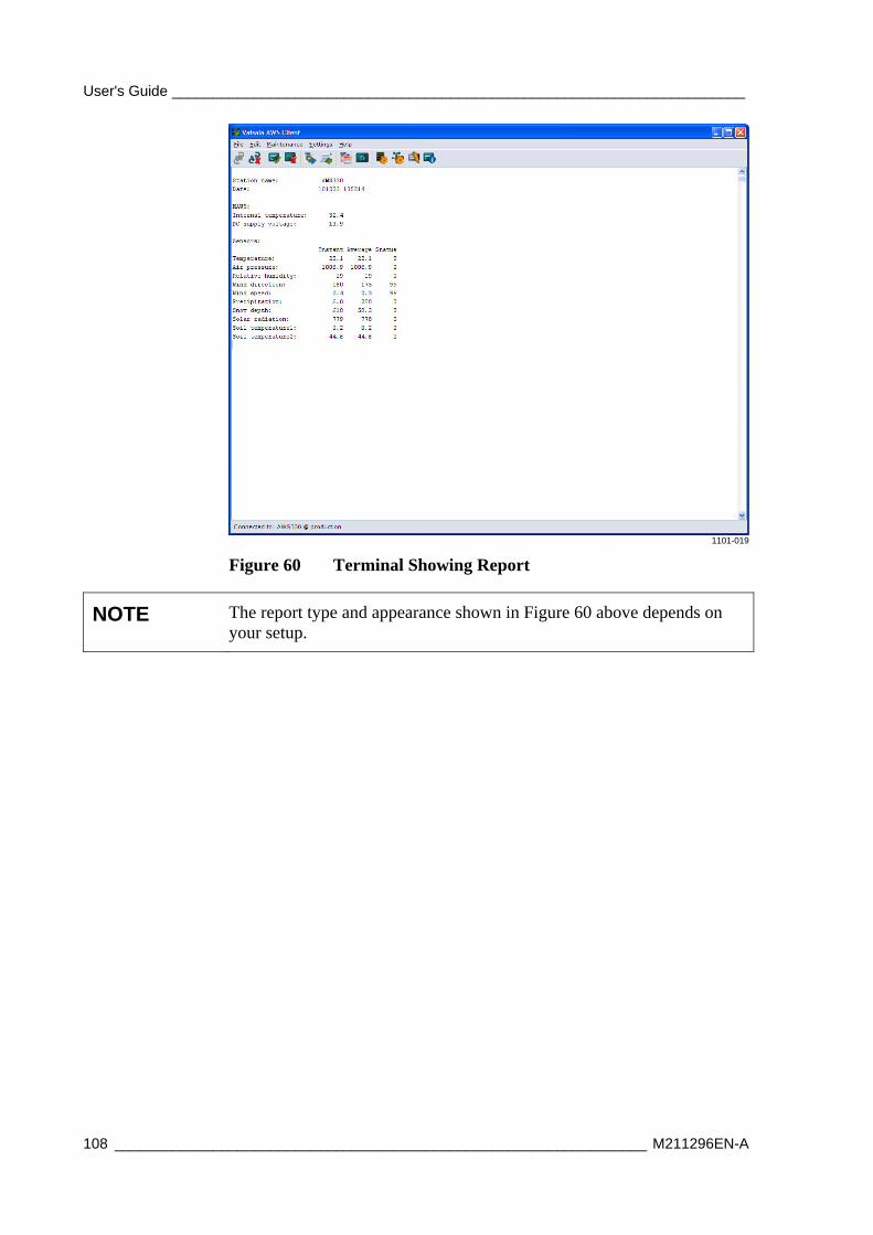
User's Guide ______________________________________________________________________
108 _________________________________________________________________ M211296EN-A
1101-019
Figure 60 Terminal Showing Report
NOTE The report type and appearance shown in Figure 60 above depends on your setup.
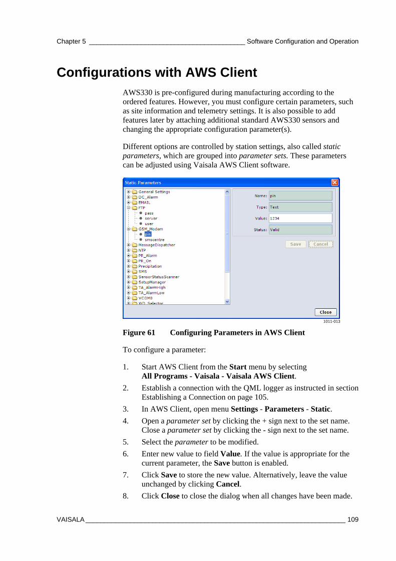
Chapter 5 __________________________________________ Software Configuration and Operation
VAISALA ______________________________________________________________________ 109
Configurations with AWS Client AWS330 is pre-configured during manufacturing according to the ordered features. However, you must configure certain parameters, such as site information and telemetry settings. It is also possible to add features later by attaching additional standard AWS330 sensors and changing the appropriate configuration parameter(s).
Different options are controlled by station settings, also called static parameters, which are grouped into parameter sets. These parameters can be adjusted using Vaisala AWS Client software.
1011-013
Figure 61 Configuring Parameters in AWS Client
To configure a parameter:
1. Start AWS Client from the Start menu by selecting All Programs - Vaisala - Vaisala AWS Client.
2. Establish a connection with the QML logger as instructed in section Establishing a Connection on page 105.
3. In AWS Client, open menu Settings - Parameters - Static.
4. Open a parameter set by clicking the + sign next to the set name. Close a parameter set by clicking the - sign next to the set name.
5. Select the parameter to be modified.
6. Enter new value to field Value. If the value is appropriate for the current parameter, the Save button is enabled.
7. Click Save to store the new value. Alternatively, leave the value unchanged by clicking Cancel.
8. Click Close to close the dialog when all changes have been made.
User's Guide ______________________________________________________________________
110 _________________________________________________________________ M211296EN-A
CAUTION Do not change values that are not instructed to be changed in this manual or by Vaisala personnel. Special care should be taken when updating parameters remotely, for example, over an IP connection. Incorrect settings can leave the AWS330 system inaccessible for further remote configuration and maintenance.
NOTE Even if some of the settings take effect immediately, it is always recommended that you reset the system when all planned changes to the settings have been completed.
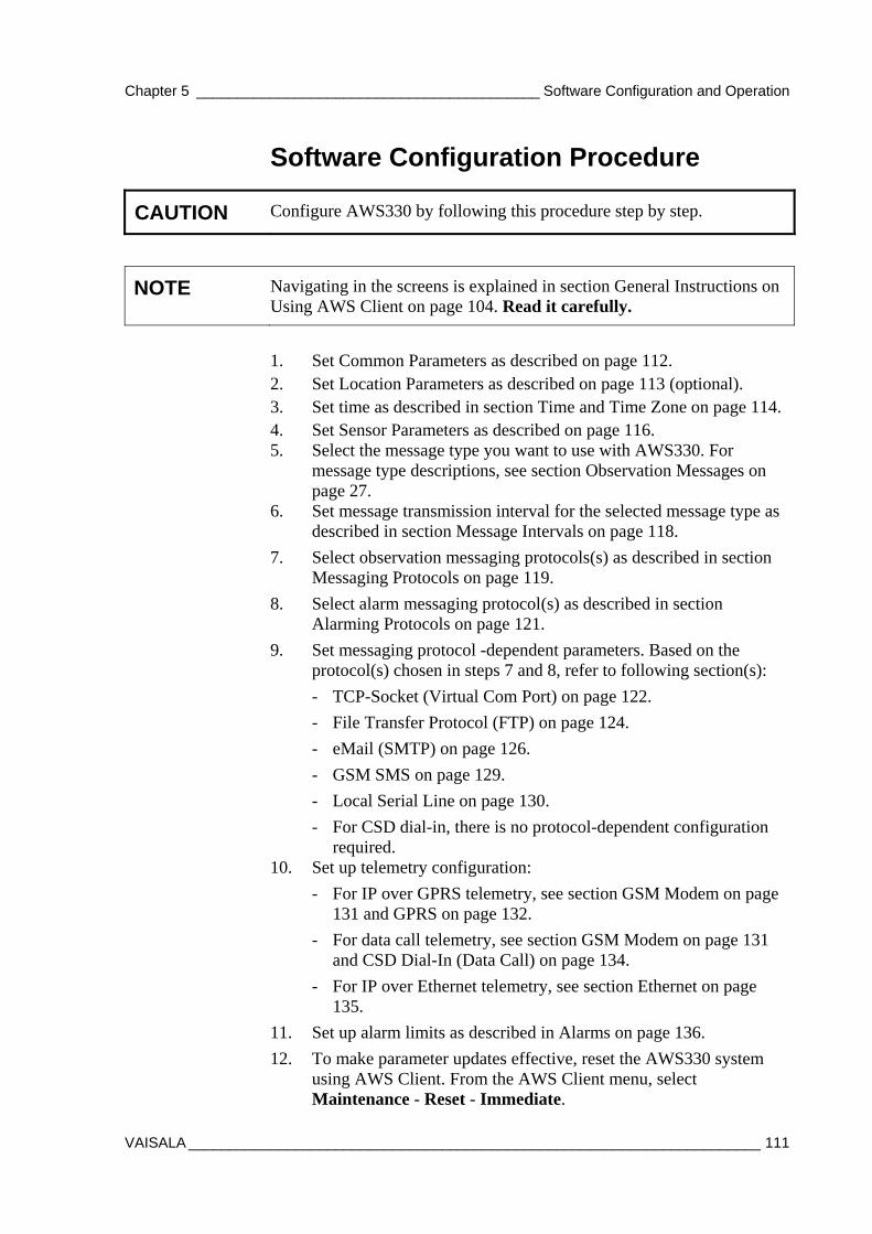
Chapter 5 __________________________________________ Software Configuration and Operation
VAISALA ______________________________________________________________________ 111
Software Configuration Procedure
CAUTION Configure AWS330 by following this procedure step by step.
NOTE Navigating in the screens is explained in section General Instructions on Using AWS Client on page 104. Read it carefully.
1. Set Common Parameters as described on page 112. 2. Set Location Parameters as described on page 113 (optional). 3. Set time as described in section Time and Time Zone on page 114. 4. Set Sensor Parameters as described on page 116. 5. Select the message type you want to use with AWS330. For
message type descriptions, see section Observation Messages on page 27.
6. Set message transmission interval for the selected message type as described in section Message Intervals on page 118.
7. Select observation messaging protocols(s) as described in section Messaging Protocols on page 119.
8. Select alarm messaging protocol(s) as described in section Alarming Protocols on page 121.
9. Set messaging protocol -dependent parameters. Based on the protocol(s) chosen in steps 7 and 8, refer to following section(s):
- TCP-Socket (Virtual Com Port) on page 122.
- File Transfer Protocol (FTP) on page 124.
- eMail (SMTP) on page 126.
- GSM SMS on page 129.
- Local Serial Line on page 130.
- For CSD dial-in, there is no protocol-dependent configuration required.
10. Set up telemetry configuration:
- For IP over GPRS telemetry, see section GSM Modem on page 131 and GPRS on page 132.
- For data call telemetry, see section GSM Modem on page 131 and CSD Dial-In (Data Call) on page 134.
- For IP over Ethernet telemetry, see section Ethernet on page 135.
11. Set up alarm limits as described in Alarms on page 136.
12. To make parameter updates effective, reset the AWS330 system using AWS Client. From the AWS Client menu, select Maintenance - Reset - Immediate.
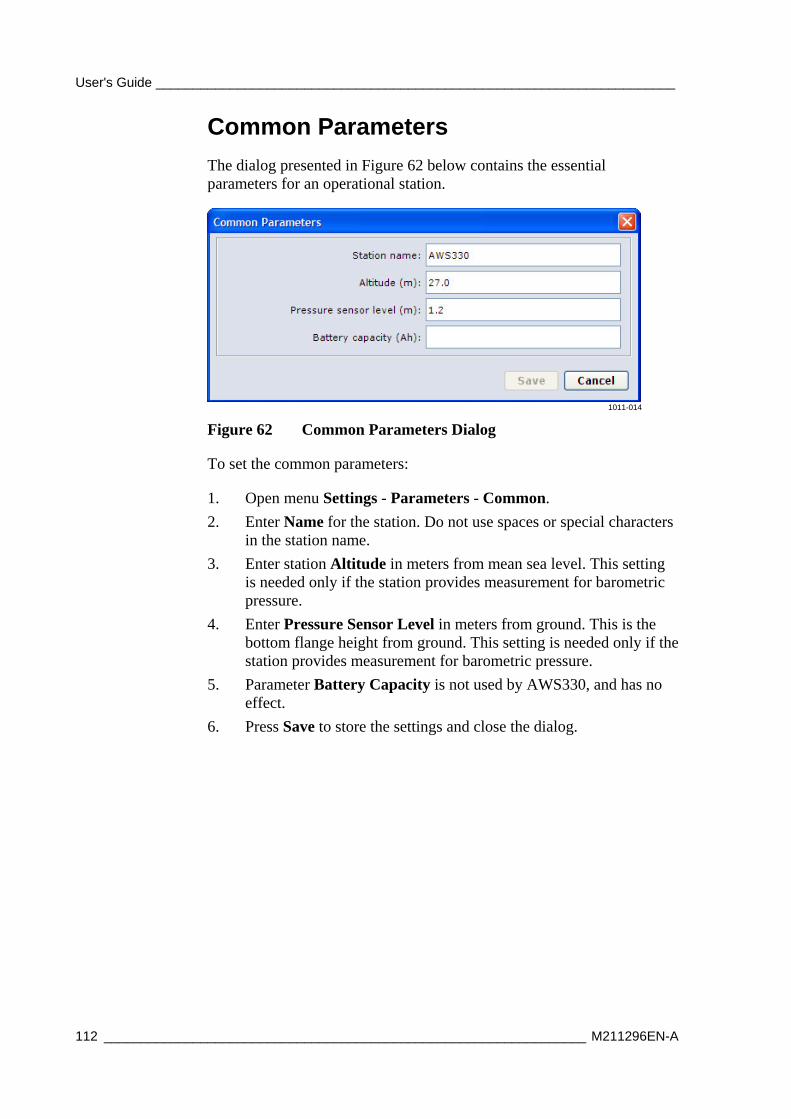
User's Guide ______________________________________________________________________
112 _________________________________________________________________ M211296EN-A
Common Parameters
The dialog presented in Figure 62 below contains the essential parameters for an operational station.
1011-014
Figure 62 Common Parameters Dialog
To set the common parameters:
1. Open menu Settings - Parameters - Common.
2. Enter Name for the station. Do not use spaces or special characters in the station name.
3. Enter station Altitude in meters from mean sea level. This setting is needed only if the station provides measurement for barometric pressure.
4. Enter Pressure Sensor Level in meters from ground. This is the bottom flange height from ground. This setting is needed only if the station provides measurement for barometric pressure.
5. Parameter Battery Capacity is not used by AWS330, and has no effect.
6. Press Save to store the settings and close the dialog.
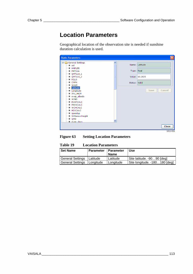
Chapter 5 __________________________________________ Software Configuration and Operation
VAISALA ______________________________________________________________________ 113
Location Parameters
Geographical location of the observation site is needed if sunshine duration calculation is used.
1011-015
Figure 63 Setting Location Parameters
Table 19 Location Parameters Set Name Parameter Parameter
Name Use
General Settings Latitude Latitude Site latitude. -90…90 [deg] General Settings Longitude Longitude Site longitude. -180…180 [deg]
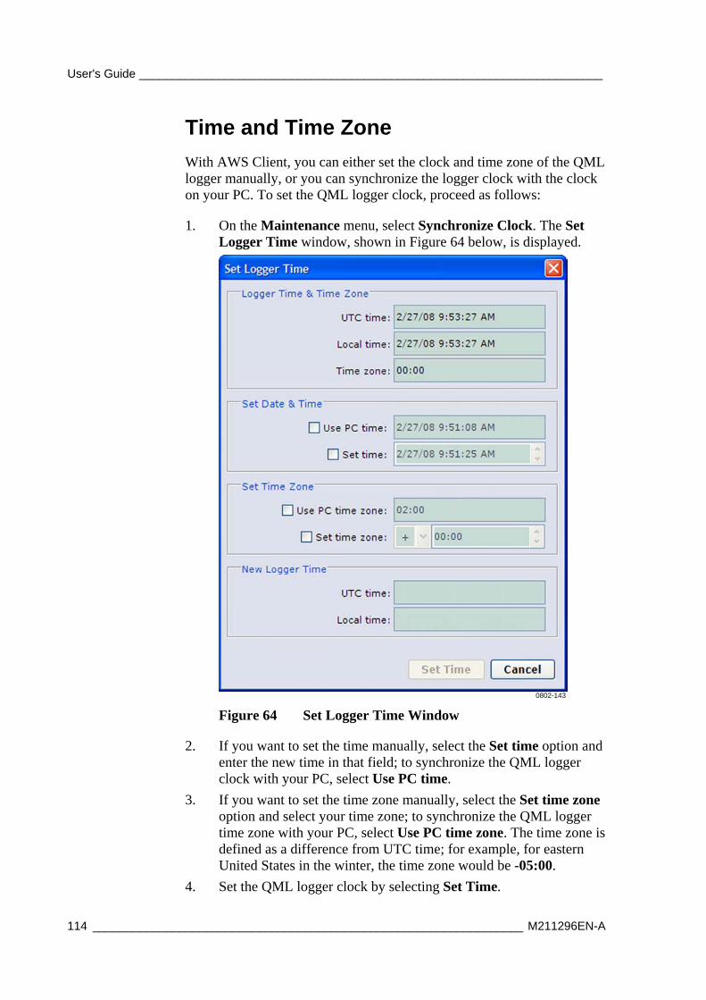
User's Guide ______________________________________________________________________
114 _________________________________________________________________ M211296EN-A
Time and Time Zone
With AWS Client, you can either set the clock and time zone of the QML logger manually, or you can synchronize the logger clock with the clock on your PC. To set the QML logger clock, proceed as follows:
1. On the Maintenance menu, select Synchronize Clock. The Set Logger Time window, shown in Figure 64 below, is displayed.
0802-143
Figure 64 Set Logger Time Window
2. If you want to set the time manually, select the Set time option and enter the new time in that field; to synchronize the QML logger clock with your PC, select Use PC time.
3. If you want to set the time zone manually, select the Set time zone option and select your time zone; to synchronize the QML logger time zone with your PC, select Use PC time zone. The time zone is defined as a difference from UTC time; for example, for eastern United States in the winter, the time zone would be -05:00.
4. Set the QML logger clock by selecting Set Time.
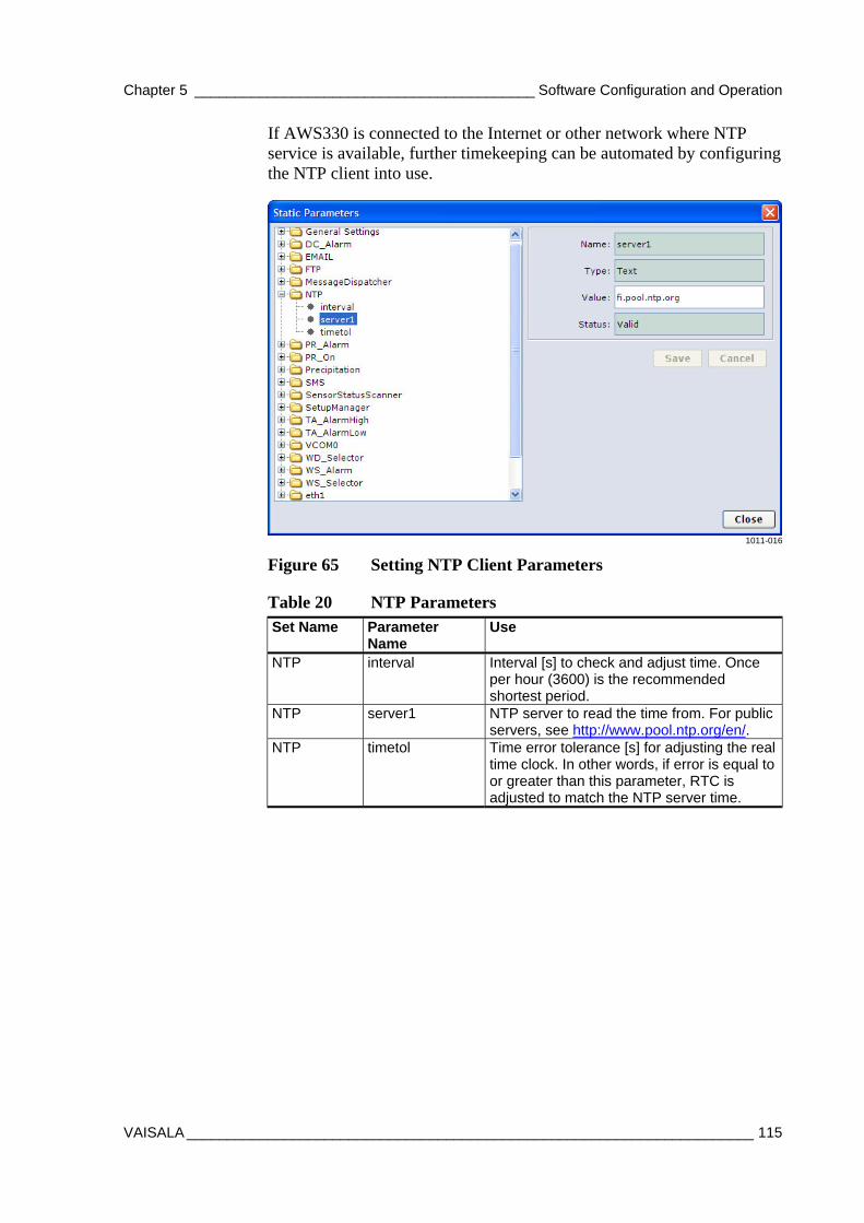
Chapter 5 __________________________________________ Software Configuration and Operation
VAISALA ______________________________________________________________________ 115
If AWS330 is connected to the Internet or other network where NTP service is available, further timekeeping can be automated by configuring the NTP client into use.
1011-016
Figure 65 Setting NTP Client Parameters
Table 20 NTP Parameters Set Name Parameter
Name Use
NTP interval Interval [s] to check and adjust time. Once per hour (3600) is the recommended shortest period.
NTP server1 NTP server to read the time from. For public servers, see http://www.pool.ntp.org/en/.
NTP timetol Time error tolerance [s] for adjusting the real time clock. In other words, if error is equal to or greater than this parameter, RTC is adjusted to match the NTP server time.
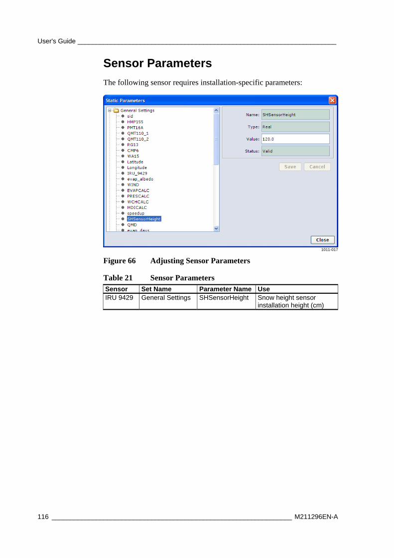
User's Guide ______________________________________________________________________
116 _________________________________________________________________ M211296EN-A
Sensor Parameters
The following sensor requires installation-specific parameters:
1011-017
Figure 66 Adjusting Sensor Parameters
Table 21 Sensor Parameters Sensor Set Name Parameter Name Use IRU 9429 General Settings SHSensorHeight Snow height sensor
installation height (cm)
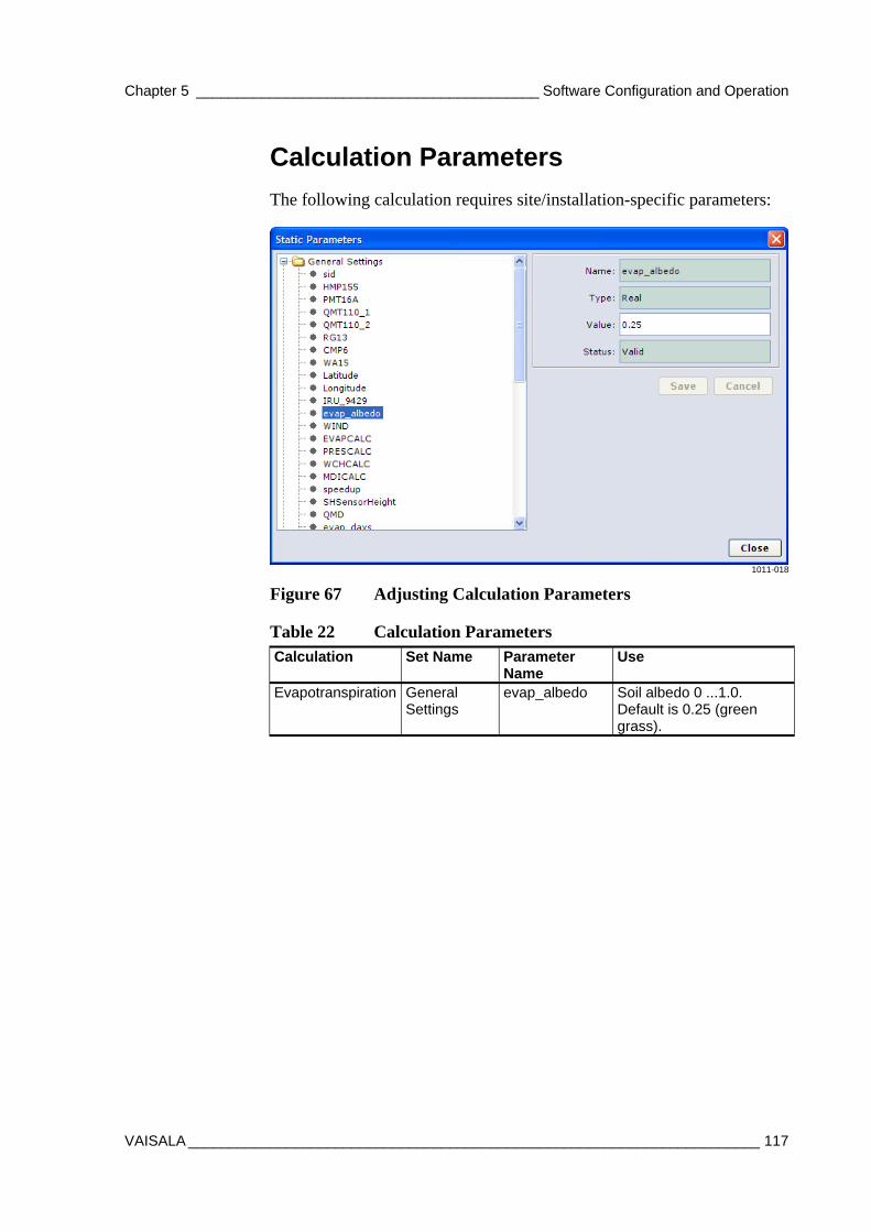
Chapter 5 __________________________________________ Software Configuration and Operation
VAISALA ______________________________________________________________________ 117
Calculation Parameters
The following calculation requires site/installation-specific parameters:
1011-018
Figure 67 Adjusting Calculation Parameters
Table 22 Calculation Parameters Calculation Set Name Parameter
Name Use
Evapotranspiration General Settings
evap_albedo Soil albedo 0 ...1.0. Default is 0.25 (green grass).
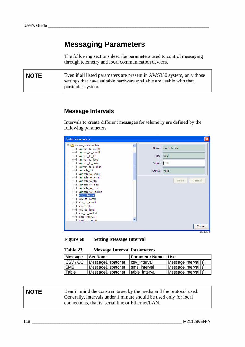
User's Guide ______________________________________________________________________
118 _________________________________________________________________ M211296EN-A
Messaging Parameters
The following sections describe parameters used to control messaging through telemetry and local communication devices.
NOTE Even if all listed parameters are present in AWS330 system, only those settings that have suitable hardware available are usable with that particular system.
Message Intervals
Intervals to create different messages for telemetry are defined by the following parameters:
1011-019
Figure 68 Setting Message Interval
Table 23 Message Interval Parameters Message Set Name Parameter Name Use CSV / OC MessageDispatcher csv_interval Message interval [s] SMS MessageDispatcher sms_interval Message interval [s] Table MessageDispatcher table_interval Message interval [s]
NOTE Bear in mind the constraints set by the media and the protocol used. Generally, intervals under 1 minute should be used only for local connections, that is, serial line or Ethernet/LAN.
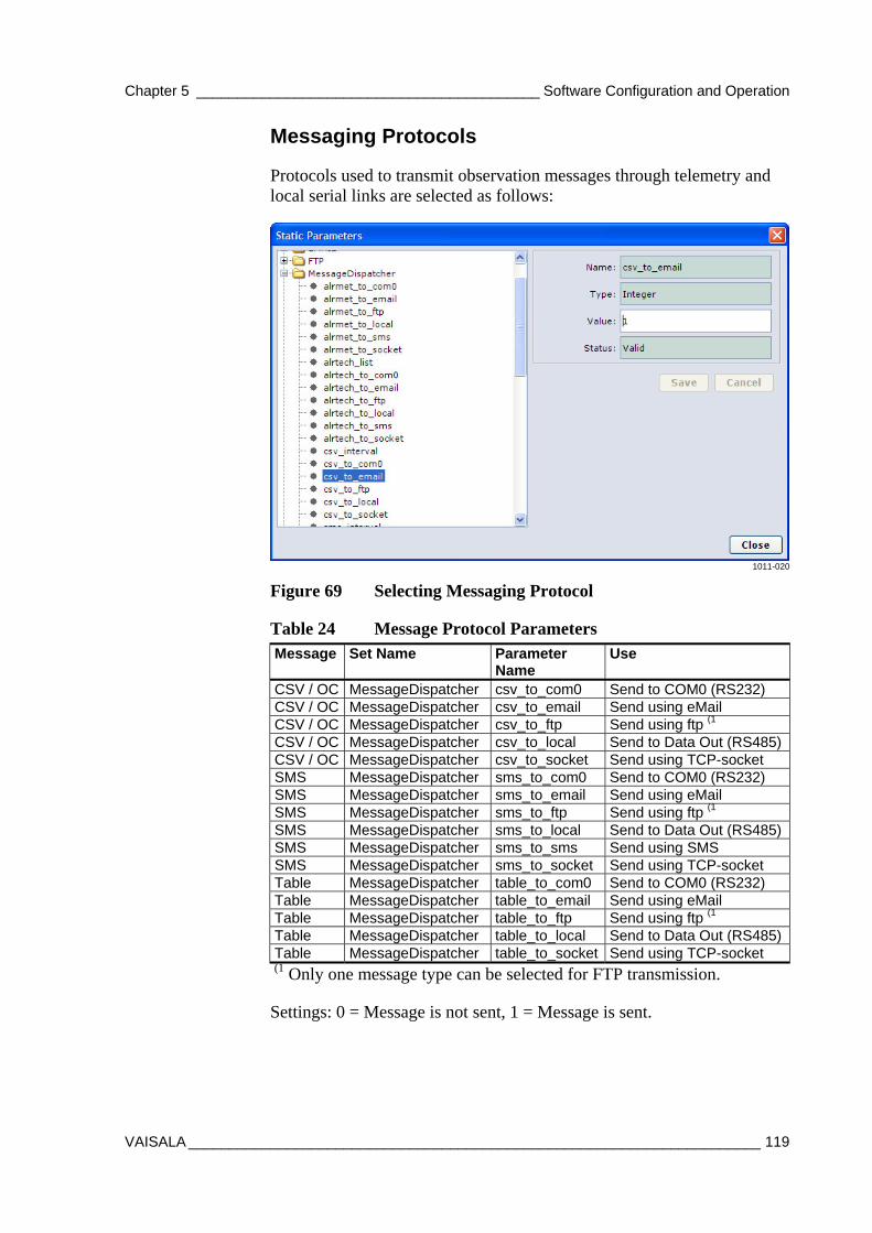
Chapter 5 __________________________________________ Software Configuration and Operation
VAISALA ______________________________________________________________________ 119
Messaging Protocols
Protocols used to transmit observation messages through telemetry and local serial links are selected as follows:
1011-020
Figure 69 Selecting Messaging Protocol
Table 24 Message Protocol Parameters Message Set Name Parameter
Name Use
CSV / OC MessageDispatcher csv_to_com0 Send to COM0 (RS232) CSV / OC MessageDispatcher csv_to_email Send using eMail CSV / OC MessageDispatcher csv_to_ftp Send using ftp (1 CSV / OC MessageDispatcher csv_to_local Send to Data Out (RS485)CSV / OC MessageDispatcher csv_to_socket Send using TCP-socket SMS MessageDispatcher sms_to_com0 Send to COM0 (RS232) SMS MessageDispatcher sms_to_email Send using eMail SMS MessageDispatcher sms_to_ftp Send using ftp (1 SMS MessageDispatcher sms_to_local Send to Data Out (RS485)SMS MessageDispatcher sms_to_sms Send using SMS SMS MessageDispatcher sms_to_socket Send using TCP-socket Table MessageDispatcher table_to_com0 Send to COM0 (RS232) Table MessageDispatcher table_to_email Send using eMail Table MessageDispatcher table_to_ftp Send using ftp (1 Table MessageDispatcher table_to_local Send to Data Out (RS485)Table MessageDispatcher table_to_socket Send using TCP-socket
(1 Only one message type can be selected for FTP transmission.
Settings: 0 = Message is not sent, 1 = Message is sent.
User's Guide ______________________________________________________________________
120 _________________________________________________________________ M211296EN-A
NOTE Socket, FTP, and eMail transmission require an IP-capable media, that is, Ethernet or GPRS.
NOTE All messages are not suitable for all protocols. CSV and Table messages cannot be transmitted using SMS due to the limited size of the SMS message (160 characters).
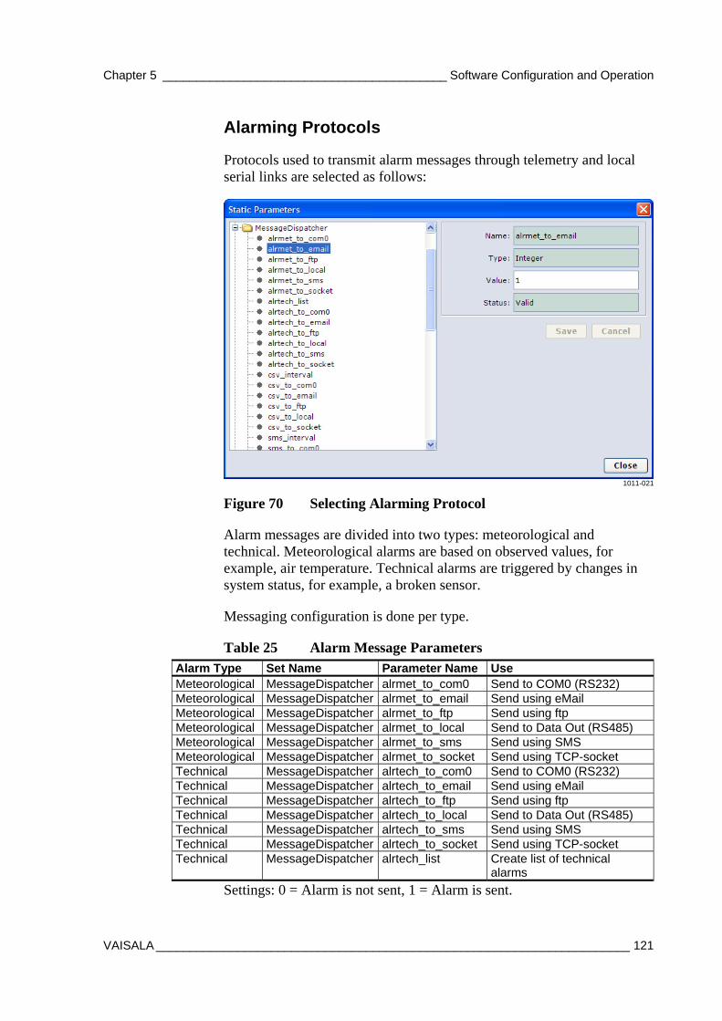
Chapter 5 __________________________________________ Software Configuration and Operation
VAISALA ______________________________________________________________________ 121
Alarming Protocols
Protocols used to transmit alarm messages through telemetry and local serial links are selected as follows:
1011-021
Figure 70 Selecting Alarming Protocol
Alarm messages are divided into two types: meteorological and technical. Meteorological alarms are based on observed values, for example, air temperature. Technical alarms are triggered by changes in system status, for example, a broken sensor.
Messaging configuration is done per type.
Table 25 Alarm Message Parameters Alarm Type Set Name Parameter Name Use Meteorological MessageDispatcher alrmet_to_com0 Send to COM0 (RS232) Meteorological MessageDispatcher alrmet_to_email Send using eMail Meteorological MessageDispatcher alrmet_to_ftp Send using ftp Meteorological MessageDispatcher alrmet_to_local Send to Data Out (RS485) Meteorological MessageDispatcher alrmet_to_sms Send using SMS Meteorological MessageDispatcher alrmet_to_socket Send using TCP-socket Technical MessageDispatcher alrtech_to_com0 Send to COM0 (RS232) Technical MessageDispatcher alrtech_to_email Send using eMail Technical MessageDispatcher alrtech_to_ftp Send using ftp Technical MessageDispatcher alrtech_to_local Send to Data Out (RS485) Technical MessageDispatcher alrtech_to_sms Send using SMS Technical MessageDispatcher alrtech_to_socket Send using TCP-socket Technical MessageDispatcher alrtech_list Create list of technical
alarms
Settings: 0 = Alarm is not sent, 1 = Alarm is sent.
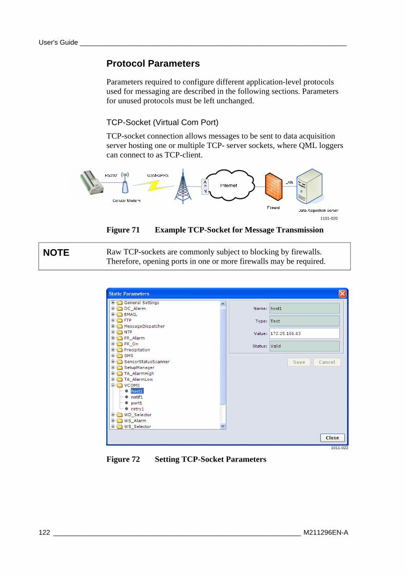
User's Guide ______________________________________________________________________
122 _________________________________________________________________ M211296EN-A
Protocol Parameters
Parameters required to configure different application-level protocols used for messaging are described in the following sections. Parameters for unused protocols must be left unchanged.
TCP-Socket (Virtual Com Port)
TCP-socket connection allows messages to be sent to data acquisition server hosting one or multiple TCP- server sockets, where QML loggers can connect to as TCP-client.
1101-020
Figure 71 Example TCP-Socket for Message Transmission
NOTE Raw TCP-sockets are commonly subject to blocking by firewalls. Therefore, opening ports in one or more firewalls may be required.
1011-022
Figure 72 Setting TCP-Socket Parameters
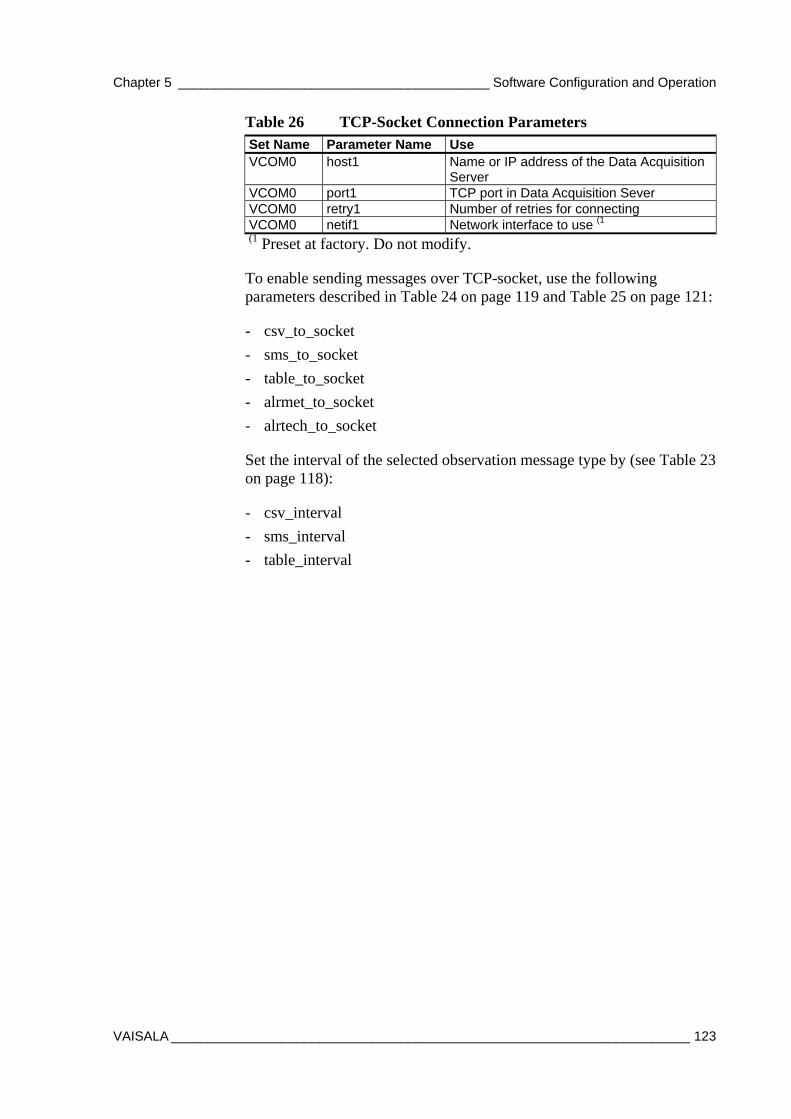
Chapter 5 __________________________________________ Software Configuration and Operation
VAISALA ______________________________________________________________________ 123
Table 26 TCP-Socket Connection Parameters Set Name Parameter Name Use VCOM0 host1 Name or IP address of the Data Acquisition
Server VCOM0 port1 TCP port in Data Acquisition Sever VCOM0 retry1 Number of retries for connecting VCOM0 netif1 Network interface to use (1 (1 Preset at factory. Do not modify.
To enable sending messages over TCP-socket, use the following parameters described in Table 24 on page 119 and Table 25 on page 121:
- csv_to_socket
- sms_to_socket
- table_to_socket
- alrmet_to_socket
- alrtech_to_socket
Set the interval of the selected observation message type by (see Table 23 on page 118):
- csv_interval
- sms_interval
- table_interval
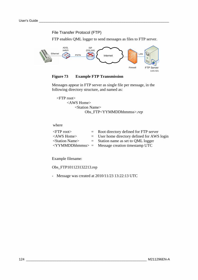
User's Guide ______________________________________________________________________
124 _________________________________________________________________ M211296EN-A
File Transfer Protocol (FTP)
FTP enables QML logger to send messages as files to FTP server.
InternetEthernet LAN
Firewall FTP Server
ADSL switch
ISP (DSLAM)
PSTN
1101-021
Figure 73 Example FTP Transmission
Messages appear in FTP server as single file per message, in the following directory structure, and named as:
<FTP root> <AWS Home> <Station Name> Obs_FTP<YYMMDDhhmmss>.rep
where
<FTP root> = Root directory defined for FTP server <AWS Home> = User home directory defined for AWS login <Station Name> = Station name as set to QML logger <YYMMDDhhmmss> = Message creation timestamp UTC
Example filename:
Obs_FTP101123132213.rep
- Message was created at 2010/11/23 13:22:13 UTC
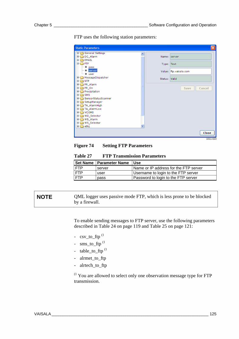
Chapter 5 __________________________________________ Software Configuration and Operation
VAISALA ______________________________________________________________________ 125
FTP uses the following station parameters:
1011-023
Figure 74 Setting FTP Parameters
Table 27 FTP Transmission Parameters Set Name Parameter Name Use FTP server Name or IP address for the FTP server FTP user Username to login to the FTP server FTP pass Password to login to the FTP server
NOTE QML logger uses passive mode FTP, which is less prone to be blocked by a firewall.
To enable sending messages to FTP server, use the following parameters described in Table 24 on page 119 and Table 25 on page 121:
- csv_to_ftp (1
- sms_to_ftp (1
- table_to_ftp (1
- alrmet_to_ftp
- alrtech_to_ftp
(1 You are allowed to select only one observation message type for FTP transmission.
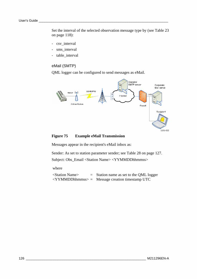
User's Guide ______________________________________________________________________
126 _________________________________________________________________ M211296EN-A
Set the interval of the selected observation message type by (see Table 23 on page 118):
- csv_interval
- sms_interval
- table_interval
eMail (SMTP)
QML logger can be configured to send messages as eMail.
1101-022
Figure 75 Example eMail Transmission
Messages appear in the recipient's eMail inbox as:
Sender: As set to station parameter sender; see Table 28 on page 127.
Subject: Obs_Email <Station Name> <YYMMDDhhmmss>
where
<Station Name> = Station name as set to the QML logger <YYMMDDhhmmss> = Message creation timestamp UTC
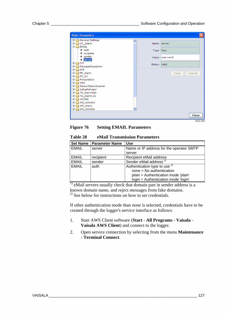
Chapter 5 __________________________________________ Software Configuration and Operation
VAISALA ______________________________________________________________________ 127
1012-163
Figure 76 Setting EMAIL Parameters
Table 28 eMail Transmission Parameters Set Name Parameter Name Use EMAIL server Name or IP address for the operator SMTP
server EMAIL recipient Recipient eMail address EMAIL sender Sender eMail address (1 EMAIL auth Authentication type to use (2
none = No authentication plain = Authentication mode 'plain' login = Authentication mode 'login'
1) eMail servers usually check that domain part in sender address is a known domain name, and reject messages from fake domains. 2) See below for instructions on how to set credentials.
If other authentication mode than none is selected, credentials have to be created through the logger's service interface as follows:
1. Start AWS Client software (Start - All Programs - Vaisala - Vaisala AWS Client) and connect to the logger.
2. Open service connection by selecting from the menu Maintenance - Terminal Connect.
User's Guide ______________________________________________________________________
128 _________________________________________________________________ M211296EN-A
3. Enter the following commands:
/> paramset hosts:<server>:smtp username <username> /> paramset hosts:<server>:smtp password <password> where
<server> = Name of the operator SMTP server <username> = Username to use for login <password> = Password to use for login
For example:
/> paramset hosts:mail.inet.fi:smtp username me /> paramset hosts:mail.inet.fi:smtp password mysecret
4. Close the service connection by selecting from the menu
Maintenance - Terminal Disconnect.
To enable sending messages via eMail server, use the following parameters described in on page 119 and Table 25 on page 121:
- csv_to_email (1
- sms_to_email (1
- table_to_email (1
- alrmet_to_email
- alrtech_to_email
(1 You are allowed to select only one observation message type for eMail transmission.
Set the interval of the selected observation message type by (see Table 23 on page 118):
- csv_interval
- sms_interval
- table_interval
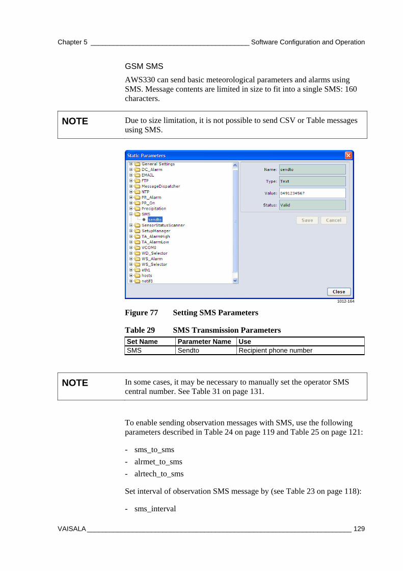
Chapter 5 __________________________________________ Software Configuration and Operation
VAISALA ______________________________________________________________________ 129
GSM SMS
AWS330 can send basic meteorological parameters and alarms using SMS. Message contents are limited in size to fit into a single SMS: 160 characters.
NOTE Due to size limitation, it is not possible to send CSV or Table messages using SMS.
1012-164
Figure 77 Setting SMS Parameters
Table 29 SMS Transmission Parameters Set Name Parameter Name Use SMS Sendto Recipient phone number
NOTE In some cases, it may be necessary to manually set the operator SMS central number. See Table 31 on page 131.
To enable sending observation messages with SMS, use the following parameters described in Table 24 on page 119 and Table 25 on page 121:
- sms_to_sms
- alrmet_to_sms
- alrtech_to_sms
Set interval of observation SMS message by (see Table 23 on page 118):
- sms_interval
User's Guide ______________________________________________________________________
130 _________________________________________________________________ M211296EN-A
Local Serial Line
Observation and alarm messages can be sent over local RS232 and RS485 lines. The following line parameters are fixed in AWS for both COM0 (RS232) and Data Out (RS485):
Table 30 Serial Line Parameters Parameter Value Speed 9600 bps Data bits 8 Stop bits 1 Parity None
Use the following parameters to control which messages are sent to local serial lines (see Table 24 on page 119 and Table 25 on page 121):
- csv_to_com0
- csv_to_local
- table_to_com0
- table_to_local
- sms_to_com0
- sms_to_local
- alrmet_to_local
- alrmet_to_com0
- alrtech_to_local
- alrtech_to_com0
Set interval of the selected observation message type by (see Table 23 on page 118):
- csv_interval
- sms_interval
- table_interval
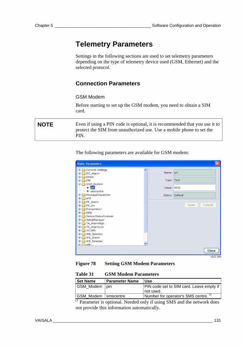
Chapter 5 __________________________________________ Software Configuration and Operation
VAISALA ______________________________________________________________________ 131
Telemetry Parameters
Settings in the following sections are used to set telemetry parameters depending on the type of telemetry device used (GSM, Ethernet) and the selected protocol.
Connection Parameters
GSM Modem
Before starting to set up the GSM modem, you need to obtain a SIM card.
NOTE Even if using a PIN code is optional, it is recommended that you use it to protect the SIM from unauthorized use. Use a mobile phone to set the PIN.
The following parameters are available for GSM modem:
1012-165
Figure 78 Setting GSM Modem Parameters
Table 31 GSM Modem Parameters Set Name Parameter Name Use GSM_Modem pin PIN code set to SIM card. Leave empty if
not used. GSM_Modem smscentre Number for operator's SMS centre. (1
(1 Parameter is optional. Needed only if using SMS and the network does not provide this information automatically.
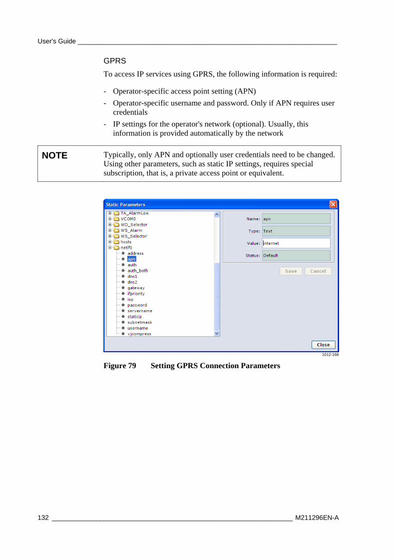
User's Guide ______________________________________________________________________
132 _________________________________________________________________ M211296EN-A
GPRS
To access IP services using GPRS, the following information is required:
- Operator-specific access point setting (APN)
- Operator-specific username and password. Only if APN requires user credentials
- IP settings for the operator's network (optional). Usually, this information is provided automatically by the network
NOTE Typically, only APN and optionally user credentials need to be changed. Using other parameters, such as static IP settings, requires special subscription, that is, a private access point or equivalent.
1012-166
Figure 79 Setting GPRS Connection Parameters
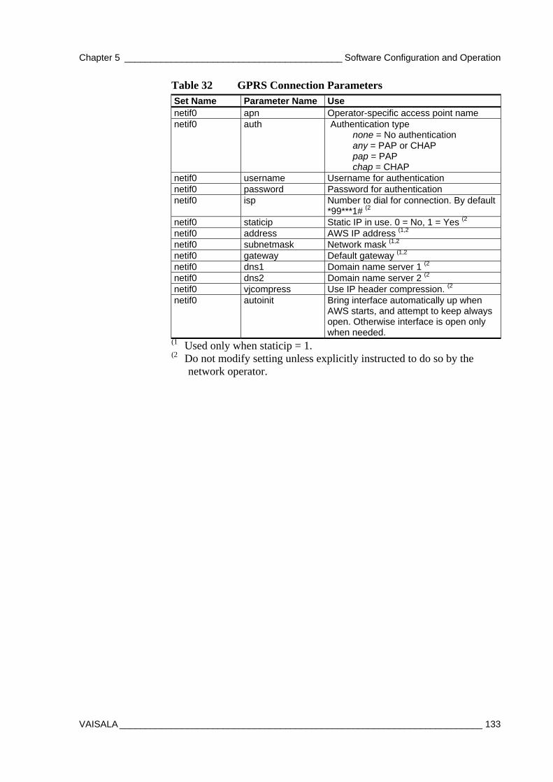
Chapter 5 __________________________________________ Software Configuration and Operation
VAISALA ______________________________________________________________________ 133
Table 32 GPRS Connection Parameters Set Name Parameter Name Use netif0 apn Operator-specific access point name netif0 auth Authentication type
none = No authentication any = PAP or CHAP pap = PAP chap = CHAP
netif0 username Username for authentication netif0 password Password for authentication netif0 isp Number to dial for connection. By default
*99***1# (2 netif0 staticip Static IP in use. 0 = No, 1 = Yes (2 netif0 address AWS IP address (1,2 netif0 subnetmask Network mask (1,2 netif0 gateway Default gateway (1,2 netif0 dns1 Domain name server 1 (2 netif0 dns2 Domain name server 2 (2 netif0 vjcompress Use IP header compression. (2 netif0 autoinit Bring interface automatically up when
AWS starts, and attempt to keep always open. Otherwise interface is open only when needed.
(1 Used only when staticip = 1. (2 Do not modify setting unless explicitly instructed to do so by the
network operator.
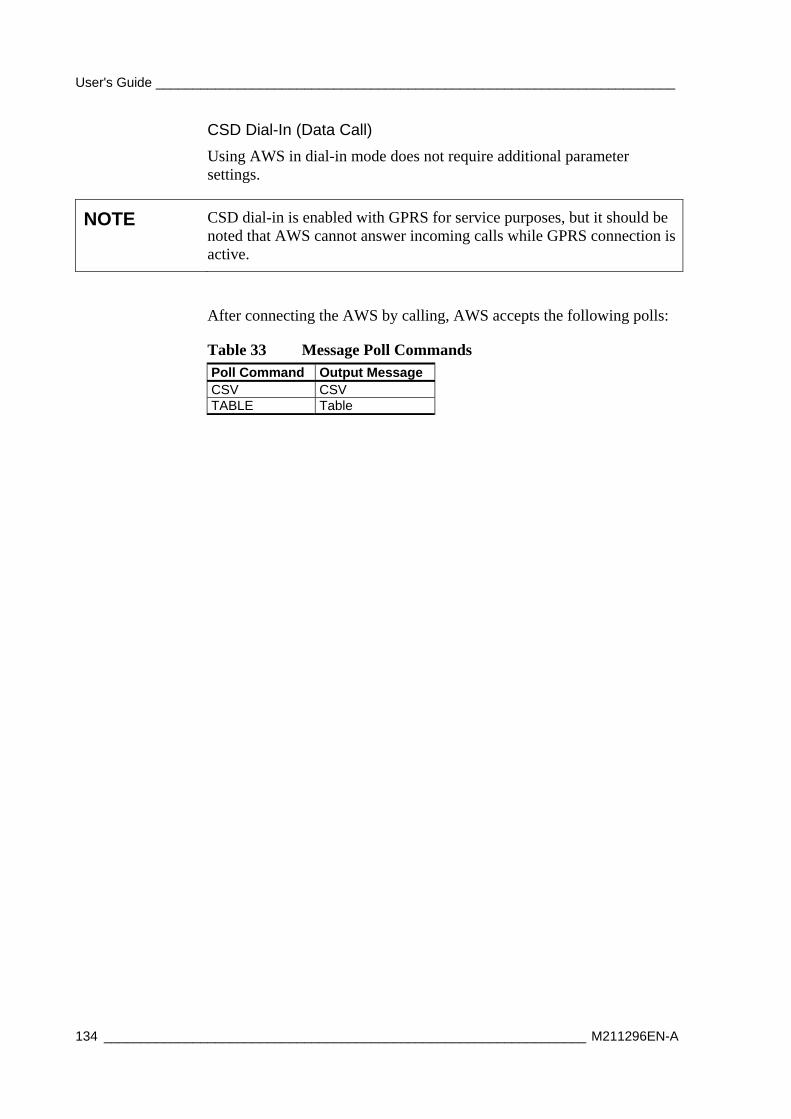
User's Guide ______________________________________________________________________
134 _________________________________________________________________ M211296EN-A
CSD Dial-In (Data Call)
Using AWS in dial-in mode does not require additional parameter settings.
NOTE CSD dial-in is enabled with GPRS for service purposes, but it should be noted that AWS cannot answer incoming calls while GPRS connection is active.
After connecting the AWS by calling, AWS accepts the following polls:
Table 33 Message Poll Commands Poll Command Output Message CSV CSV TABLE Table
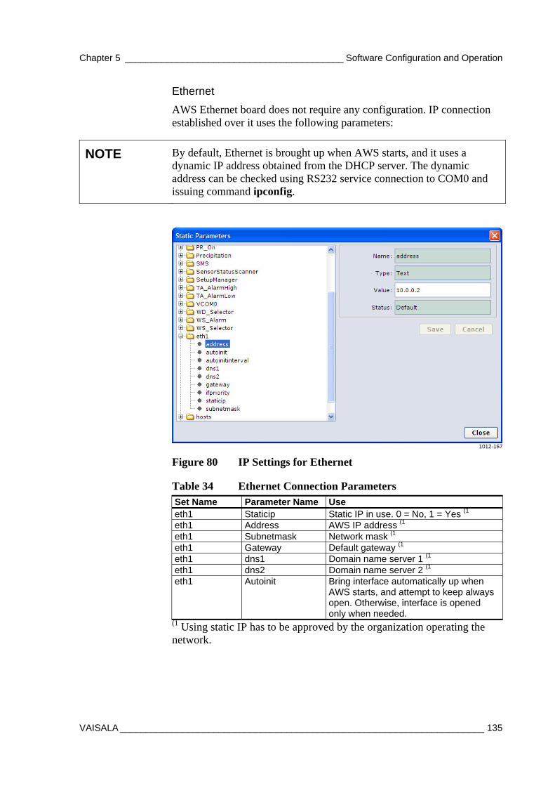
Chapter 5 __________________________________________ Software Configuration and Operation
VAISALA ______________________________________________________________________ 135
Ethernet
AWS Ethernet board does not require any configuration. IP connection established over it uses the following parameters:
NOTE By default, Ethernet is brought up when AWS starts, and it uses a dynamic IP address obtained from the DHCP server. The dynamic address can be checked using RS232 service connection to COM0 and issuing command ipconfig.
1012-167
Figure 80 IP Settings for Ethernet
Table 34 Ethernet Connection Parameters Set Name Parameter Name Use eth1 Staticip Static IP in use. 0 = No, 1 = Yes (1 eth1 Address AWS IP address (1 eth1 Subnetmask Network mask (1 eth1 Gateway Default gateway (1 eth1 dns1 Domain name server 1 (1 eth1 dns2 Domain name server 2 (1 eth1 Autoinit Bring interface automatically up when
AWS starts, and attempt to keep always open. Otherwise, interface is opened only when needed.
(1 Using static IP has to be approved by the organization operating the network.
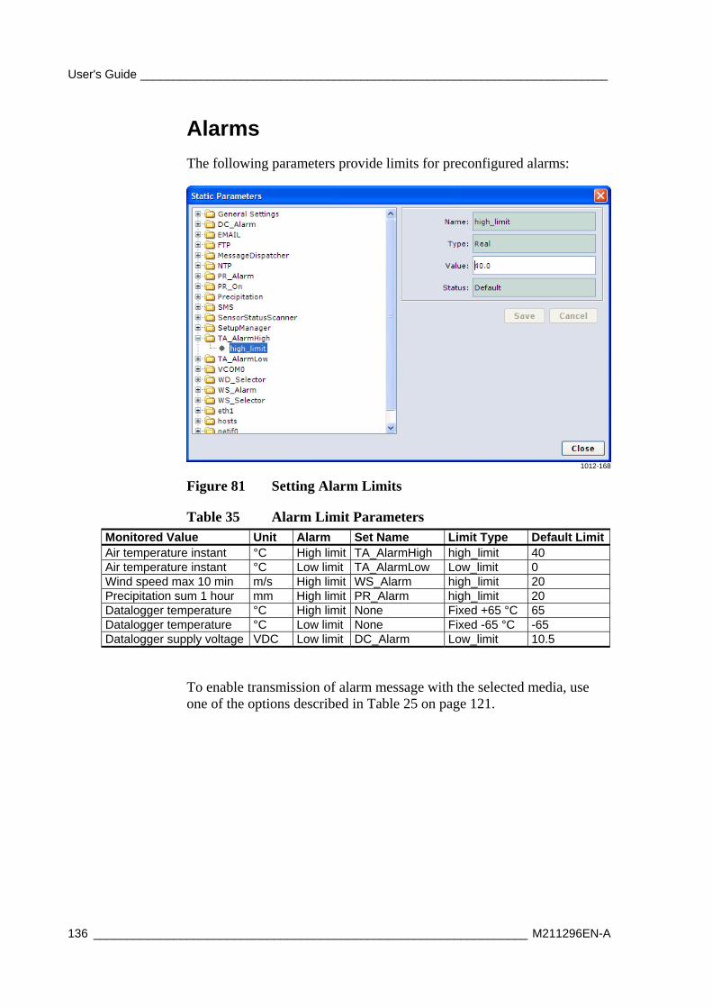
User's Guide ______________________________________________________________________
136 _________________________________________________________________ M211296EN-A
Alarms
The following parameters provide limits for preconfigured alarms:
1012-168
Figure 81 Setting Alarm Limits
Table 35 Alarm Limit Parameters Monitored Value Unit Alarm Set Name Limit Type Default LimitAir temperature instant °C High limit TA_AlarmHigh high_limit 40 Air temperature instant °C Low limit TA_AlarmLow Low_limit 0 Wind speed max 10 min m/s High limit WS_Alarm high_limit 20 Precipitation sum 1 hour mm High limit PR_Alarm high_limit 20 Datalogger temperature °C High limit None Fixed +65 °C 65 Datalogger temperature °C Low limit None Fixed -65 °C -65 Datalogger supply voltage VDC Low limit DC_Alarm Low_limit 10.5
To enable transmission of alarm message with the selected media, use one of the options described in Table 25 on page 121.
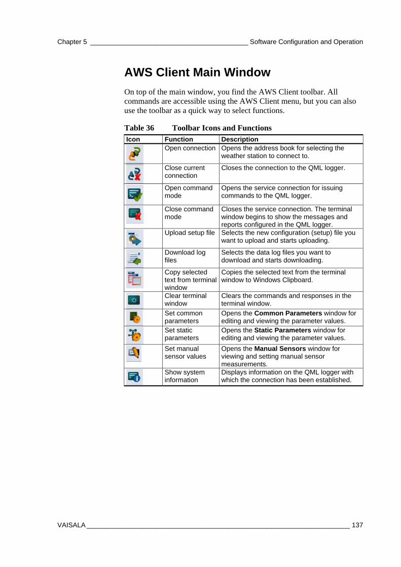
Chapter 5 __________________________________________ Software Configuration and Operation
VAISALA ______________________________________________________________________ 137
AWS Client Main Window
On top of the main window, you find the AWS Client toolbar. All commands are accessible using the AWS Client menu, but you can also use the toolbar as a quick way to select functions.
Table 36 Toolbar Icons and Functions Icon Function Description
Open connection Opens the address book for selecting the weather station to connect to.
Close current connection
Closes the connection to the QML logger.
Open command mode
Opens the service connection for issuing commands to the QML logger.
Close command mode
Closes the service connection. The terminal window begins to show the messages and reports configured in the QML logger.
Upload setup file Selects the new configuration (setup) file you want to upload and starts uploading.
Download log files
Selects the data log files you want to download and starts downloading.
Copy selected text from terminal window
Copies the selected text from the terminal window to Windows Clipboard.
Clear terminal window
Clears the commands and responses in the terminal window.
Set common parameters
Opens the Common Parameters window for editing and viewing the parameter values.
Set static parameters
Opens the Static Parameters window for editing and viewing the parameter values.
Set manual sensor values
Opens the Manual Sensors window for viewing and setting manual sensor measurements.
Show system information
Displays information on the QML logger with which the connection has been established.
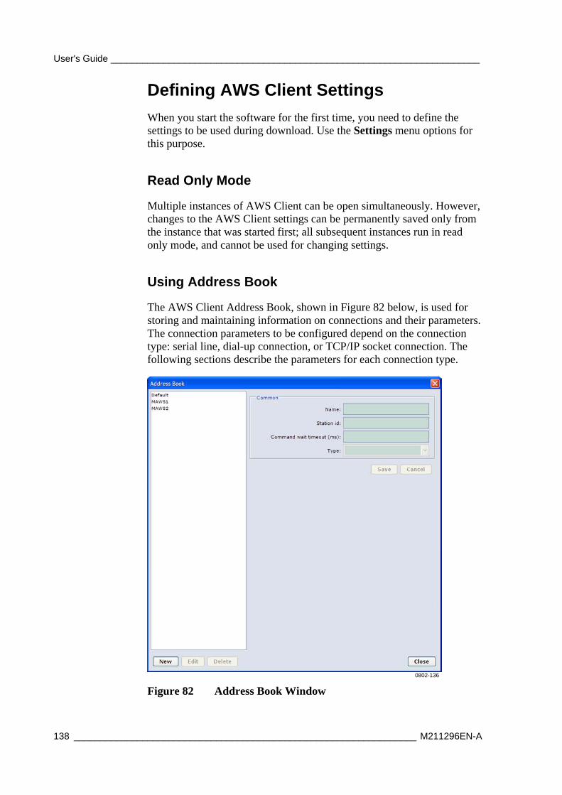
User's Guide ______________________________________________________________________
138 _________________________________________________________________ M211296EN-A
Defining AWS Client Settings
When you start the software for the first time, you need to define the settings to be used during download. Use the Settings menu options for this purpose.
Read Only Mode
Multiple instances of AWS Client can be open simultaneously. However, changes to the AWS Client settings can be permanently saved only from the instance that was started first; all subsequent instances run in read only mode, and cannot be used for changing settings.
Using Address Book
The AWS Client Address Book, shown in Figure 82 below, is used for storing and maintaining information on connections and their parameters. The connection parameters to be configured depend on the connection type: serial line, dial-up connection, or TCP/IP socket connection. The following sections describe the parameters for each connection type.
0802-136
Figure 82 Address Book Window
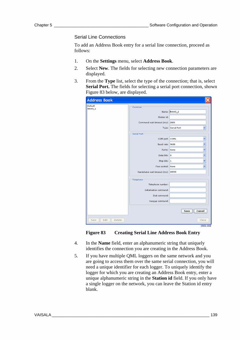
Chapter 5 __________________________________________ Software Configuration and Operation
VAISALA ______________________________________________________________________ 139
Serial Line Connections
To add an Address Book entry for a serial line connection, proceed as follows:
1. On the Settings menu, select Address Book.
2. Select New. The fields for selecting new connection parameters are displayed.
3. From the Type list, select the type of the connection; that is, select Serial Port. The fields for selecting a serial port connection, shown Figure 83 below, are displayed.
0905-008
Figure 83 Creating Serial Line Address Book Entry
4. In the Name field, enter an alphanumeric string that uniquely identifies the connection you are creating in the Address Book.
5. If you have multiple QML loggers on the same network and you are going to access them over the same serial connection, you will need a unique identifier for each logger. To uniquely identify the logger for which you are creating an Address Book entry, enter a unique alphanumeric string in the Station id field. If you only have a single logger on the network, you can leave the Station id entry blank.
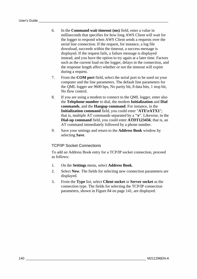
User's Guide ______________________________________________________________________
140 _________________________________________________________________ M211296EN-A
6. In the Command wait timeout (ms) field, enter a value in milliseconds that specifies for how long AWS Client will wait for the logger to respond when AWS Client sends a requests over the serial line connection. If the request, for instance, a log file download, succeeds within the timeout, a success message is displayed. If the request fails, a failure message is displayed instead, and you have the option to try again at a later time. Factors such as the current load on the logger, delays in the connection, and the response length affect whether or not the timeout will expire during a request.
7. From the COM port field, select the serial port to be used on your computer and the line parameters. The default line parameters for the QML logger are 9600 bps, No parity bit, 8 data bits, 1 stop bit, No flow control.
8. If you are using a modem to connect to the QML logger, enter also the Telephone number to dial, the modem Initialization and Dial commands, and the Hangup command. For instance, in the Initialization command field, you could enter "ATE\rATX1"; that is, multiple AT commands separated by a "\r". Likewise, in the Dial-up command field, you could enter ATDT123456; that is, an AT command immediately followed by a phone number.
9. Save your settings and return to the Address Book window by selecting Save.
TCP/IP Socket Connections
To add an Address Book entry for a TCP/IP socket connection, proceed as follows:
1. On the Settings menu, select Address Book.
2. Select New. The fields for selecting new connection parameters are displayed.
3. From the Type list, select Client socket or Server socket as the connection type. The fields for selecting the TCP/IP connection parameters, shown in Figure 84 on page 141, are displayed.
Chapter 5 __________________________________________ Software Configuration and Operation
VAISALA ______________________________________________________________________ 141
1101-023
Figure 84 Creating TCP/IP Socket Connection Address Book Entry
4. In the Name field, enter an alphanumeric string that uniquely identifies the connection you are creating in the Address Book.
5. If you have multiple QML loggers on the same network and you are going to access them over the same TCP/IP connection, you will need a unique identifier for each logger. To uniquely identify the logger for which you are creating an Address Book entry, enter a unique alphanumeric string in the Station id field. However, if you only have a single logger on the network, you can leave the Station id entry blank.
6. In the Command wait timeout (ms) field, enter a value in milliseconds that specifies for how long AWS Client will wait for the logger to respond when AWS Client sends a requests over the TCP/IP connection. If the request, for instance, a log file download, succeeds within the timeout, a success message is displayed. If the request fails, a failure message is displayed instead, and you have the option to try again at a later time. Factors such as the current load on the logger, delays in the connection, and the response length affect whether or not the timeout will expire during a request.
User's Guide ______________________________________________________________________
142 _________________________________________________________________ M211296EN-A
7. In the IP addr./DNS name field, enter the destination IP address or DNS name.
NOTE In order to use the DNS name, you must have access to a DNS server to be able to resolve the DNS name to the IP address of the destination host.
NOTE For Server socket, the target IP addr./DNS name is not available in the user interface.
8. Enter the port to be used in the Port field. Note that for Client socket, this must match the port set for incoming connections in the interface configuration in the QML logger. For Server socket, Host address and port defined for virtual COM port must match the AWS Client IP address and port.
9. If support for Telnet escape sequences for binary file transfer is required, select the Telnet option.
10. Save your settings and return to the Address Book window by selecting Save.
Dial-Up Connections
The dial-up connections are based on Windows Dial-Up Networking entries, so you first need to create the connection in Windows. For information on creating Windows Dial-Up Networking connections, please see the Windows online help. To add an Address Book entry for the dial-up connection, proceed as follows:
1. On the Settings menu, select Address Book.
2. Select New. The fields for selecting new connection parameters are displayed.
3. From the Type list, first select Socket. The field for selecting Windows Dial-Up Networking entries is available in the window shown in Figure 85 on page 143.
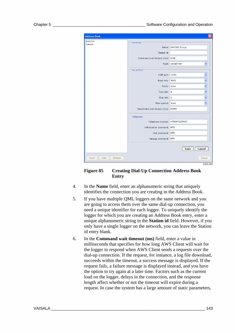
Chapter 5 __________________________________________ Software Configuration and Operation
VAISALA ______________________________________________________________________ 143
1101-024
Figure 85 Creating Dial-Up Connection Address Book Entry
4. In the Name field, enter an alphanumeric string that uniquely identifies the connection you are creating in the Address Book.
5. If you have multiple QML loggers on the same network and you are going to access them over the same dial-up connection, you need a unique identifier for each logger. To uniquely identify the logger for which you are creating an Address Book entry, enter a unique alphanumeric string in the Station id field. However, if you only have a single logger on the network, you can leave the Station id entry blank.
6. In the Command wait timeout (ms) field, enter a value in milliseconds that specifies for how long AWS Client will wait for the logger to respond when AWS Client sends a requests over the dial-up connection. If the request, for instance, a log file download, succeeds within the timeout, a success message is displayed. If the request fails, a failure message is displayed instead, and you have the option to try again at a later time. Factors such as the current load on the logger, delays in the connection, and the response length affect whether or not the timeout will expire during a request. In case the system has a large amount of static parameters,
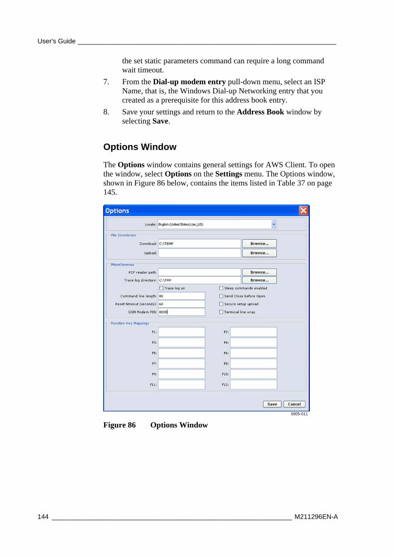
User's Guide ______________________________________________________________________
144 _________________________________________________________________ M211296EN-A
the set static parameters command can require a long command wait timeout.
7. From the Dial-up modem entry pull-down menu, select an ISP Name, that is, the Windows Dial-up Networking entry that you created as a prerequisite for this address book entry.
8. Save your settings and return to the Address Book window by selecting Save.
Options Window
The Options window contains general settings for AWS Client. To open the window, select Options on the Settings menu. The Options window, shown in Figure 86 below, contains the items listed in Table 37 on page 145.
0905-011
Figure 86 Options Window
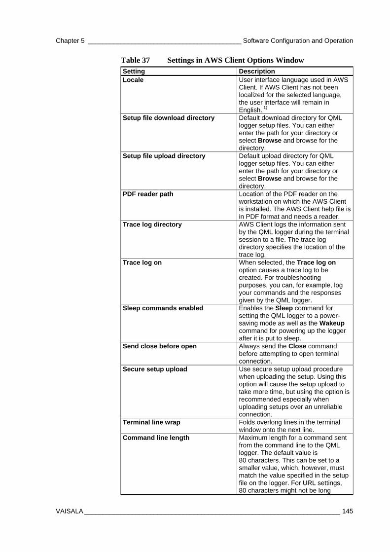
Chapter 5 __________________________________________ Software Configuration and Operation
VAISALA ______________________________________________________________________ 145
Table 37 Settings in AWS Client Options Window Setting Description Locale User interface language used in AWS
Client. If AWS Client has not been localized for the selected language, the user interface will remain in English. 1)
Setup file download directory Default download directory for QML logger setup files. You can either enter the path for your directory or select Browse and browse for the directory.
Setup file upload directory Default upload directory for QML logger setup files. You can either enter the path for your directory or select Browse and browse for the directory.
PDF reader path Location of the PDF reader on the workstation on which the AWS Client is installed. The AWS Client help file is in PDF format and needs a reader.
Trace log directory AWS Client logs the information sent by the QML logger during the terminal session to a file. The trace log directory specifies the location of the trace log.
Trace log on When selected, the Trace log on option causes a trace log to be created. For troubleshooting purposes, you can, for example, log your commands and the responses given by the QML logger.
Sleep commands enabled Enables the Sleep command for setting the QML logger to a power-saving mode as well as the Wakeup command for powering up the logger after it is put to sleep.
Send close before open Always send the Close command before attempting to open terminal connection.
Secure setup upload Use secure setup upload procedure when uploading the setup. Using this option will cause the setup upload to take more time, but using the option is recommended especially when uploading setups over an unreliable connection.
Terminal line wrap Folds overlong lines in the terminal window onto the next line.
Command line length Maximum length for a command sent from the command line to the QML logger. The default value is 80 characters. This can be set to a smaller value, which, however, must match the value specified in the setup file on the logger. For URL settings, 80 characters might not be long
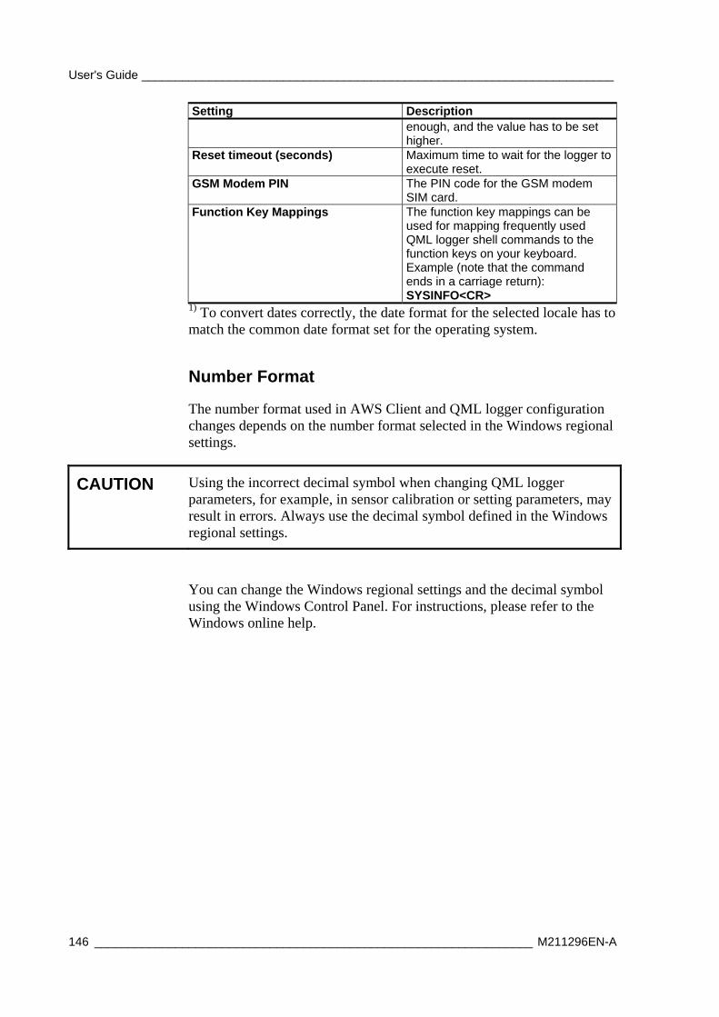
User's Guide ______________________________________________________________________
146 _________________________________________________________________ M211296EN-A
Setting Description enough, and the value has to be set higher.
Reset timeout (seconds) Maximum time to wait for the logger to execute reset.
GSM Modem PIN The PIN code for the GSM modem SIM card.
Function Key Mappings The function key mappings can be used for mapping frequently used QML logger shell commands to the function keys on your keyboard. Example (note that the command ends in a carriage return): SYSINFO<CR>
1) To convert dates correctly, the date format for the selected locale has to match the common date format set for the operating system.
Number Format
The number format used in AWS Client and QML logger configuration changes depends on the number format selected in the Windows regional settings.
CAUTION Using the incorrect decimal symbol when changing QML logger parameters, for example, in sensor calibration or setting parameters, may result in errors. Always use the decimal symbol defined in the Windows regional settings.
You can change the Windows regional settings and the decimal symbol using the Windows Control Panel. For instructions, please refer to the Windows online help.
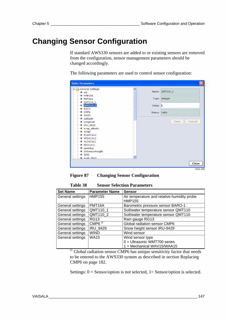
Chapter 5 __________________________________________ Software Configuration and Operation
VAISALA ______________________________________________________________________ 147
Changing Sensor Configuration If standard AWS330 sensors are added to or existing sensors are removed from the configuration, sensor management parameters should be changed accordingly.
The following parameters are used to control sensor configuration:
1012-169
Figure 87 Changing Sensor Configuration
Table 38 Sensor Selection Parameters Set Name Parameter Name Sensor General settings HMP155 Air temperature and relative humidity probe
HMP155 General settings PMT16A Barometric pressure sensor BARO-1 General settings QMT110_1 Soil/water temperature sensor QMT110 General settings QMT110_2 Soil/water temperature sensor QMT110 General settings RG13 Rain gauge RG13 General settings CMP6 (1 Global radiation sensor CMP6 General settings IRU_9429 Snow height sensor IRU-9429 General settings WIND Wind sensor General settings WA15 Wind sensor type
0 = Ultrasonic WMT700 series 1 = Mechanical WAV15/WAA15
(1 Global radiation sensor CMP6 has unique sensitivity factor that needs to be entered to the AWS330 system as described in section Replacing CMP6 on page 182.
Settings: 0 = Sensor/option is not selected, 1= Sensor/option is selected.
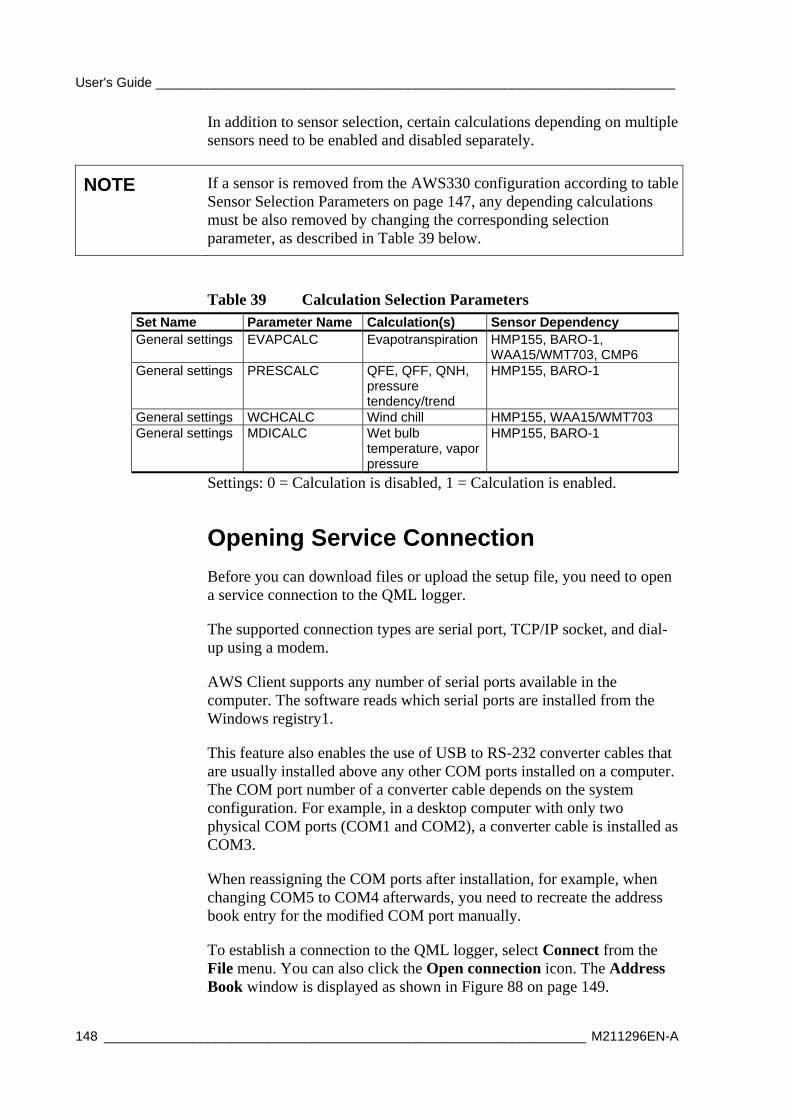
User's Guide ______________________________________________________________________
148 _________________________________________________________________ M211296EN-A
In addition to sensor selection, certain calculations depending on multiple sensors need to be enabled and disabled separately.
NOTE If a sensor is removed from the AWS330 configuration according to table Sensor Selection Parameters on page 147, any depending calculations must be also removed by changing the corresponding selection parameter, as described in Table 39 below.
Table 39 Calculation Selection Parameters Set Name Parameter Name Calculation(s) Sensor Dependency General settings EVAPCALC Evapotranspiration HMP155, BARO-1,
WAA15/WMT703, CMP6 General settings PRESCALC QFE, QFF, QNH,
pressure tendency/trend
HMP155, BARO-1
General settings WCHCALC Wind chill HMP155, WAA15/WMT703 General settings MDICALC Wet bulb
temperature, vapor pressure
HMP155, BARO-1
Settings: 0 = Calculation is disabled, 1 = Calculation is enabled.
Opening Service Connection
Before you can download files or upload the setup file, you need to open a service connection to the QML logger.
The supported connection types are serial port, TCP/IP socket, and dial-up using a modem.
AWS Client supports any number of serial ports available in the computer. The software reads which serial ports are installed from the Windows registry1.
This feature also enables the use of USB to RS-232 converter cables that are usually installed above any other COM ports installed on a computer. The COM port number of a converter cable depends on the system configuration. For example, in a desktop computer with only two physical COM ports (COM1 and COM2), a converter cable is installed as COM3.
When reassigning the COM ports after installation, for example, when changing COM5 to COM4 afterwards, you need to recreate the address book entry for the modified COM port manually.
To establish a connection to the QML logger, select Connect from the File menu. You can also click the Open connection icon. The Address Book window is displayed as shown in Figure 88 on page 149.
Chapter 5 __________________________________________ Software Configuration and Operation
VAISALA ______________________________________________________________________ 149
0802-141
Figure 88 Address Book Window
In the Address Book window, select the address book entry for the QML logger and click OK.
To open the service connection, select Terminal Connect on the Maintenance menu or click the Open command mode button on the toolbar. You can also type the open command with your keyboard and press enter. Note that the typed characters are not echoed on the screen.
When the connection is opened, the following text appears on your screen:
Service connection opened />
User's Guide ______________________________________________________________________
150 _________________________________________________________________ M211296EN-A
Giving Commands
When you have established the connection to the QML logger, you can use the commands described in Table 40 below to communicate with the QML logger. Commands are text strings sent from the PC or terminal to the logger.
To open the connection, select Terminal Connect on the Maintenance menu or click the Open command mode button on the toolbar. To close the terminal connection, select Terminal Disconnect on the Maintenance menu or click the Close command mode button on the toolbar. Logging is not affected unless it is stopped using the logstop command. In the closed mode, the serial line will be available for report sending.
NOTE Both open and close commands have to be typed in the exactly correct way before they can be executed. This means that you cannot use the BACKSPACE key to correct your typing. Simply retype the command and press ENTER to give the command again.
Most of the commands can be used for both setting a value for a parameter and viewing the set value of a parameter.
Type help to get a list of available commands. Each command must be entered using the correct syntax. You do not have to memorize complex commands since you can view a help text that shows the correct syntax at any time. Simply type help and the command name.
Table 40 Interpreting Help Texts (Correct Syntax) Generic Representation
Example Note
To see the warnings, type: warnings
Use the parameter name
warnings [clear]
To remove warnings, type: warnings clear To see current time, type: time To set new time, type for example: time 15 45 00
time [HH MM SS YY MM DD]
To set new time and date, for example: time 15 45 00 07 06 18
Parameters shown in [ ] can be omitted.
Replace parameter symbols with values
loggo <group_id> Parameters shown in < > cannot be omitted.
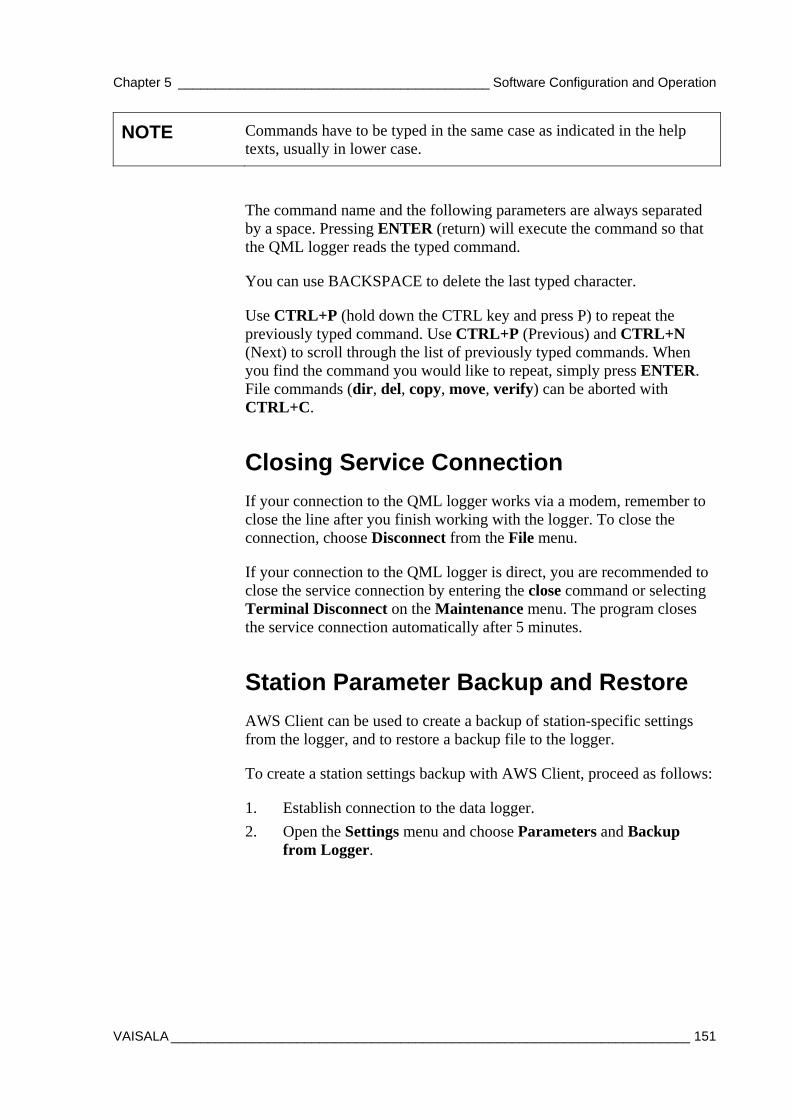
Chapter 5 __________________________________________ Software Configuration and Operation
VAISALA ______________________________________________________________________ 151
NOTE Commands have to be typed in the same case as indicated in the help texts, usually in lower case.
The command name and the following parameters are always separated by a space. Pressing ENTER (return) will execute the command so that the QML logger reads the typed command.
You can use BACKSPACE to delete the last typed character.
Use CTRL+P (hold down the CTRL key and press P) to repeat the previously typed command. Use CTRL+P (Previous) and CTRL+N (Next) to scroll through the list of previously typed commands. When you find the command you would like to repeat, simply press ENTER. File commands (dir, del, copy, move, verify) can be aborted with CTRL+C.
Closing Service Connection
If your connection to the QML logger works via a modem, remember to close the line after you finish working with the logger. To close the connection, choose Disconnect from the File menu.
If your connection to the QML logger is direct, you are recommended to close the service connection by entering the close command or selecting Terminal Disconnect on the Maintenance menu. The program closes the service connection automatically after 5 minutes.
Station Parameter Backup and Restore
AWS Client can be used to create a backup of station-specific settings from the logger, and to restore a backup file to the logger.
To create a station settings backup with AWS Client, proceed as follows:
1. Establish connection to the data logger.
2. Open the Settings menu and choose Parameters and Backup from Logger.
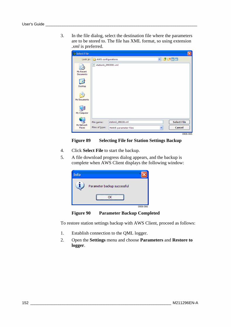
User's Guide ______________________________________________________________________
152 _________________________________________________________________ M211296EN-A
3. In the file dialog, select the destination file where the parameters are to be stored to. The file has XML format, so using extension .xml is preferred.
0906-065
Figure 89 Selecting File for Station Settings Backup
4. Click Select File to start the backup.
5. A file download progress dialog appears, and the backup is complete when AWS Client displays the following window:
0906-066
Figure 90 Parameter Backup Completed
To restore station settings backup with AWS Client, proceed as follows:
1. Establish connection to the QML logger.
2. Open the Settings menu and choose Parameters and Restore to logger.
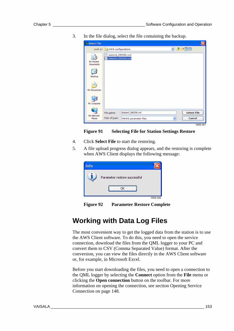
Chapter 5 __________________________________________ Software Configuration and Operation
VAISALA ______________________________________________________________________ 153
3. In the file dialog, select the file containing the backup.
0906-067
Figure 91 Selecting File for Station Settings Restore
4. Click Select File to start the restoring.
5. A file upload progress dialog appears, and the restoring is complete when AWS Client displays the following message:
0906-068
Figure 92 Parameter Restore Complete
Working with Data Log Files
The most convenient way to get the logged data from the station is to use the AWS Client software. To do this, you need to open the service connection, download the files from the QML logger to your PC and convert them to CSV (Comma Separated Value) format. After the conversion, you can view the files directly in the AWS Client software or, for example, in Microsoft Excel.
Before you start downloading the files, you need to open a connection to the QML logger by selecting the Connect option from the File menu or clicking the Open connection button on the toolbar. For more information on opening the connection, see section Opening Service Connection on page 148.
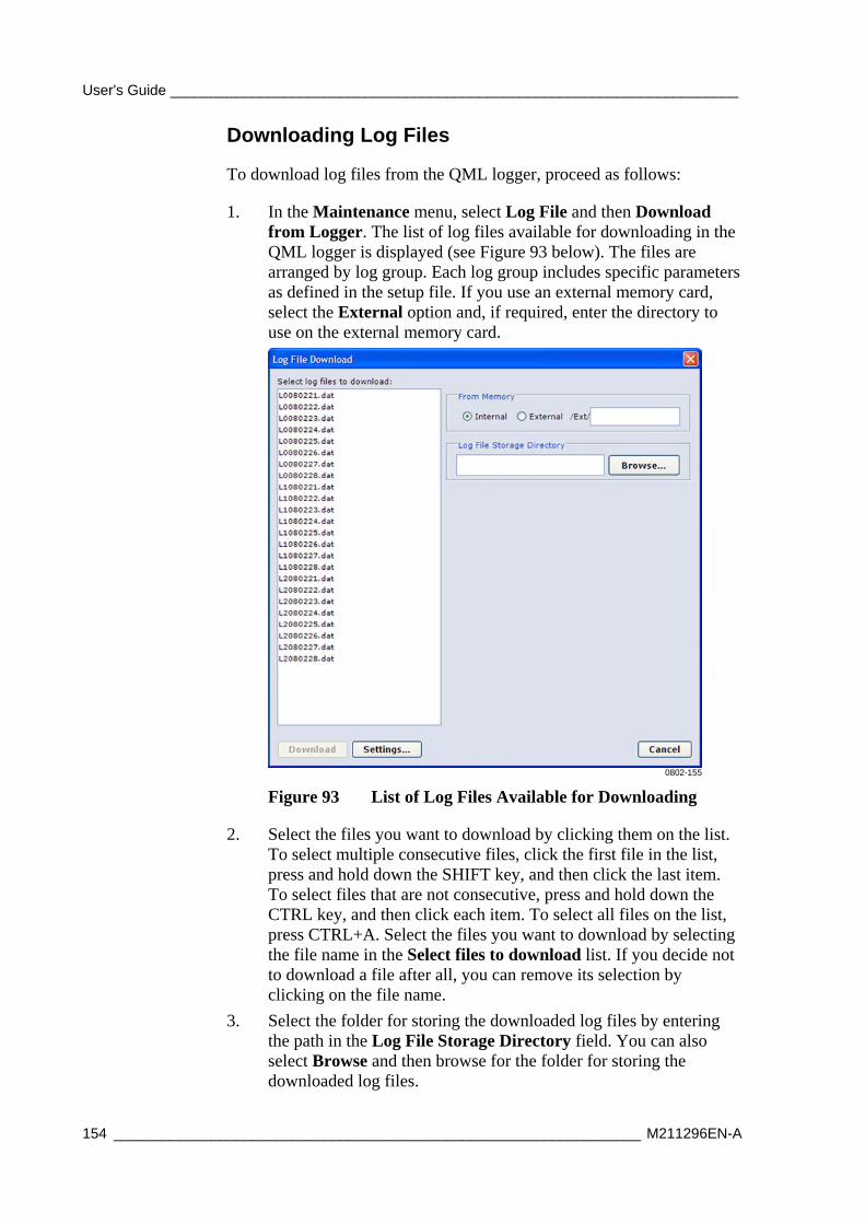
User's Guide ______________________________________________________________________
154 _________________________________________________________________ M211296EN-A
Downloading Log Files
To download log files from the QML logger, proceed as follows:
1. In the Maintenance menu, select Log File and then Download from Logger. The list of log files available for downloading in the QML logger is displayed (see Figure 93 below). The files are arranged by log group. Each log group includes specific parameters as defined in the setup file. If you use an external memory card, select the External option and, if required, enter the directory to use on the external memory card.
0802-155
Figure 93 List of Log Files Available for Downloading
2. Select the files you want to download by clicking them on the list. To select multiple consecutive files, click the first file in the list, press and hold down the SHIFT key, and then click the last item. To select files that are not consecutive, press and hold down the CTRL key, and then click each item. To select all files on the list, press CTRL+A. Select the files you want to download by selecting the file name in the Select files to download list. If you decide not to download a file after all, you can remove its selection by clicking on the file name.
3. Select the folder for storing the downloaded log files by entering the path in the Log File Storage Directory field. You can also select Browse and then browse for the folder for storing the downloaded log files.
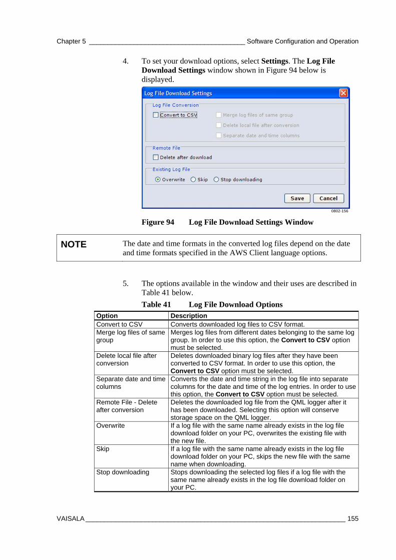
Chapter 5 __________________________________________ Software Configuration and Operation
VAISALA ______________________________________________________________________ 155
4. To set your download options, select Settings. The Log File Download Settings window shown in Figure 94 below is displayed.
0802-156
Figure 94 Log File Download Settings Window
NOTE The date and time formats in the converted log files depend on the date and time formats specified in the AWS Client language options.
5. The options available in the window and their uses are described in Table 41 below.
Table 41 Log File Download Options Option Description Convert to CSV Converts downloaded log files to CSV format. Merge log files of same group
Merges log files from different dates belonging to the same log group. In order to use this option, the Convert to CSV option must be selected.
Delete local file after conversion
Deletes downloaded binary log files after they have been converted to CSV format. In order to use this option, the Convert to CSV option must be selected.
Separate date and time columns
Converts the date and time string in the log file into separate columns for the date and time of the log entries. In order to use this option, the Convert to CSV option must be selected.
Remote File - Delete after conversion
Deletes the downloaded log file from the QML logger after it has been downloaded. Selecting this option will conserve storage space on the QML logger.
Overwrite If a log file with the same name already exists in the log file download folder on your PC, overwrites the existing file with the new file.
Skip If a log file with the same name already exists in the log file download folder on your PC, skips the new file with the same name when downloading.
Stop downloading Stops downloading the selected log files if a log file with the same name already exists in the log file download folder on your PC.
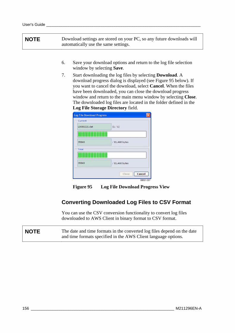
User's Guide ______________________________________________________________________
156 _________________________________________________________________ M211296EN-A
NOTE Download settings are stored on your PC, so any future downloads will automatically use the same settings.
6. Save your download options and return to the log file selection window by selecting Save.
7. Start downloading the log files by selecting Download. A download progress dialog is displayed (see Figure 95 below). If you want to cancel the download, select Cancel. When the files have been downloaded, you can close the download progress window and return to the main menu window by selecting Close. The downloaded log files are located in the folder defined in the Log File Storage Directory field.
0802-157
Figure 95 Log File Download Progress View
Converting Downloaded Log Files to CSV Format
You can use the CSV conversion functionality to convert log files downloaded to AWS Client in binary format to CSV format.
NOTE The date and time formats in the converted log files depend on the date and time formats specified in the AWS Client language options.
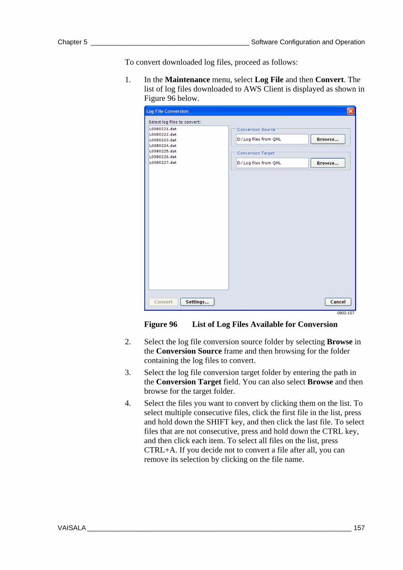
Chapter 5 __________________________________________ Software Configuration and Operation
VAISALA ______________________________________________________________________ 157
To convert downloaded log files, proceed as follows:
1. In the Maintenance menu, select Log File and then Convert. The list of log files downloaded to AWS Client is displayed as shown in Figure 96 below.
0802-157
Figure 96 List of Log Files Available for Conversion
2. Select the log file conversion source folder by selecting Browse in the Conversion Source frame and then browsing for the folder containing the log files to convert.
3. Select the log file conversion target folder by entering the path in the Conversion Target field. You can also select Browse and then browse for the target folder.
4. Select the files you want to convert by clicking them on the list. To select multiple consecutive files, click the first file in the list, press and hold down the SHIFT key, and then click the last file. To select files that are not consecutive, press and hold down the CTRL key, and then click each item. To select all files on the list, press CTRL+A. If you decide not to convert a file after all, you can remove its selection by clicking on the file name.
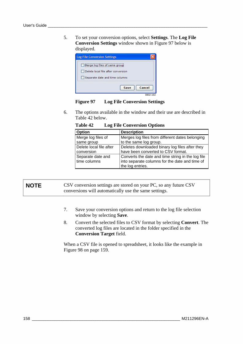
User's Guide ______________________________________________________________________
158 _________________________________________________________________ M211296EN-A
5. To set your conversion options, select Settings. The Log File Conversion Settings window shown in Figure 97 below is displayed.
0802-163
Figure 97 Log File Conversion Settings
6. The options available in the window and their use are described in Table 42 below.
Table 42 Log File Conversion Options Option Description Merge log files of same group
Merges log files from different dates belonging to the same log group.
Delete local file after conversion
Deletes downloaded binary log files after they have been converted to CSV format.
Separate date and time columns
Converts the date and time string in the log file into separate columns for the date and time of the log entries.
NOTE CSV conversion settings are stored on your PC, so any future CSV conversions will automatically use the same settings.
7. Save your conversion options and return to the log file selection window by selecting Save.
8. Convert the selected files to CSV format by selecting Convert. The converted log files are located in the folder specified in the Conversion Target field.
When a CSV file is opened to spreadsheet, it looks like the example in Figure 98 on page 159.
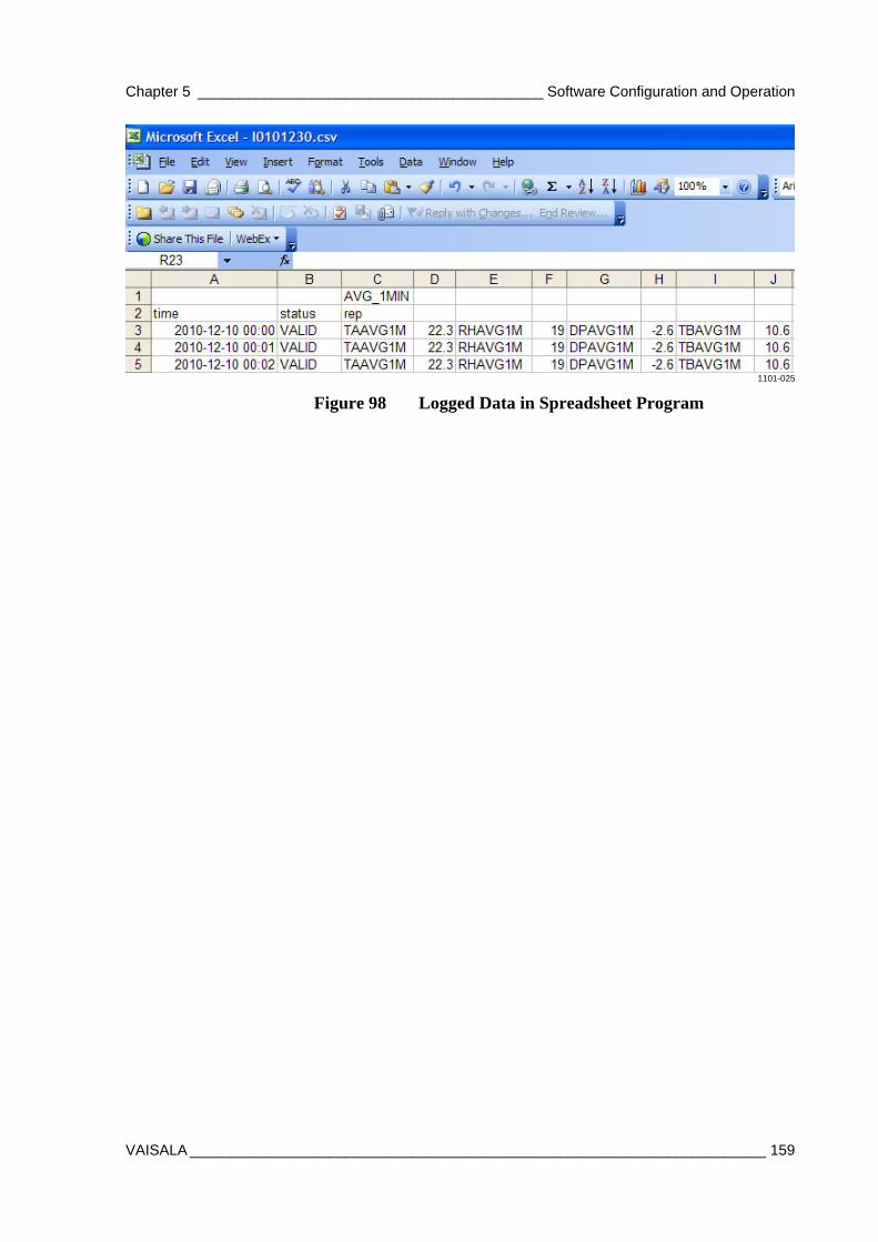
Chapter 5 __________________________________________ Software Configuration and Operation
VAISALA ______________________________________________________________________ 159
1101-025
Figure 98 Logged Data in Spreadsheet Program

User's Guide ______________________________________________________________________
160 _________________________________________________________________ M211296EN-A
Using External Memory Card The external memory card (CF card, CompactFlash) is used to store log files that have been copied or moved from the internal log directory. The data can be retrieved from the external memory card via terminal connection or by switching the memory card to an empty one.
NOTE If the CF card has not been formatted, it must be formatted before use.
It is recommended that you format the card in a Windows PC. The file system to use is FAT (not FAT32). Also, do not select the quick format option.
To format the CF card in the QML logger, insert it into the CF slot of the QML logger. Give the EXTFSERASE command. After the card has been formatted, you can remove it from the slot.
The external memory card can be removed from the QML logger for data retrieval without interruptions to operations. The logger copies data from the internal log directory to the memory card daily at midnight, the default time is 00:00:30. Data is being written when the LED on the logger cover to the left of the external memory card is constantly on.
CAUTION The memory card must not be removed from the QML logger while data is being written, or data may be lost. By default, data is transmitted to the memory card each day at 00:00:30.
When a new memory card is inserted into the QML logger, the software checks that the card is ready for use. The status of the memory card is indicated by a LED. Table 43 below describes the different blinking sequences and the card conditions they indicate.
Table 43 LED Blinking Sequences and Card Status Options Blinking Sequence Card Status Long-long Card is OK. Constantly on Data is being written. Short-short-short for 5 seconds Card is unformatted or corrupted.
Chapter 5 __________________________________________ Software Configuration and Operation
VAISALA ______________________________________________________________________ 161
Automatic Erase from External Memory Card
The log group -specific setting Number of days to preserve log files, specified in Lizard setup software, also affects the files stored to the external memory card. The functionality is the same as for internal log memory:
- Files older than the selected value [days] will be deleted automatically.
- Files are not erased, that is, the automatic cleanup is disabled.
When files are stored to the external memory card, the internal memory is used as the working memory for storing the log files of the current day. These working files are moved to the external card each day just after midnight when the new files have been created for writing.
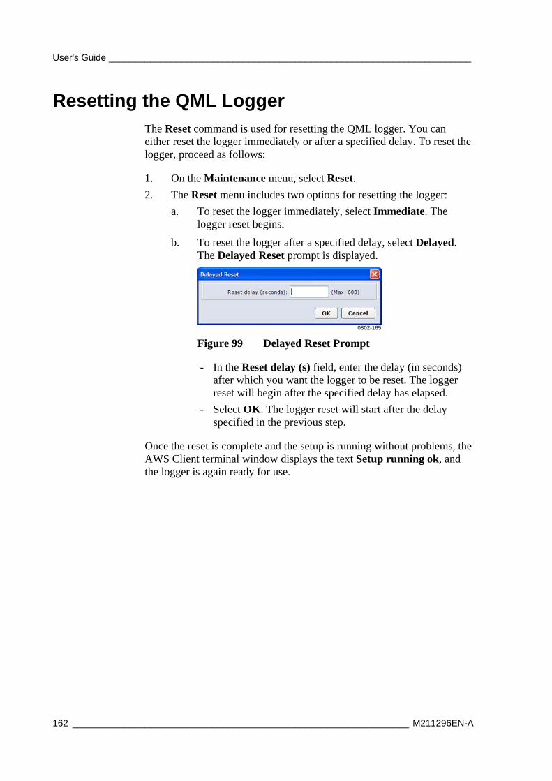
User's Guide ______________________________________________________________________
162 _________________________________________________________________ M211296EN-A
Resetting the QML Logger The Reset command is used for resetting the QML logger. You can either reset the logger immediately or after a specified delay. To reset the logger, proceed as follows:
1. On the Maintenance menu, select Reset.
2. The Reset menu includes two options for resetting the logger:
a. To reset the logger immediately, select Immediate. The logger reset begins.
b. To reset the logger after a specified delay, select Delayed. The Delayed Reset prompt is displayed.
0802-165
Figure 99 Delayed Reset Prompt
- In the Reset delay (s) field, enter the delay (in seconds) after which you want the logger to be reset. The logger reset will begin after the specified delay has elapsed.
- Select OK. The logger reset will start after the delay specified in the previous step.
Once the reset is complete and the setup is running without problems, the AWS Client terminal window displays the text Setup running ok, and the logger is again ready for use.
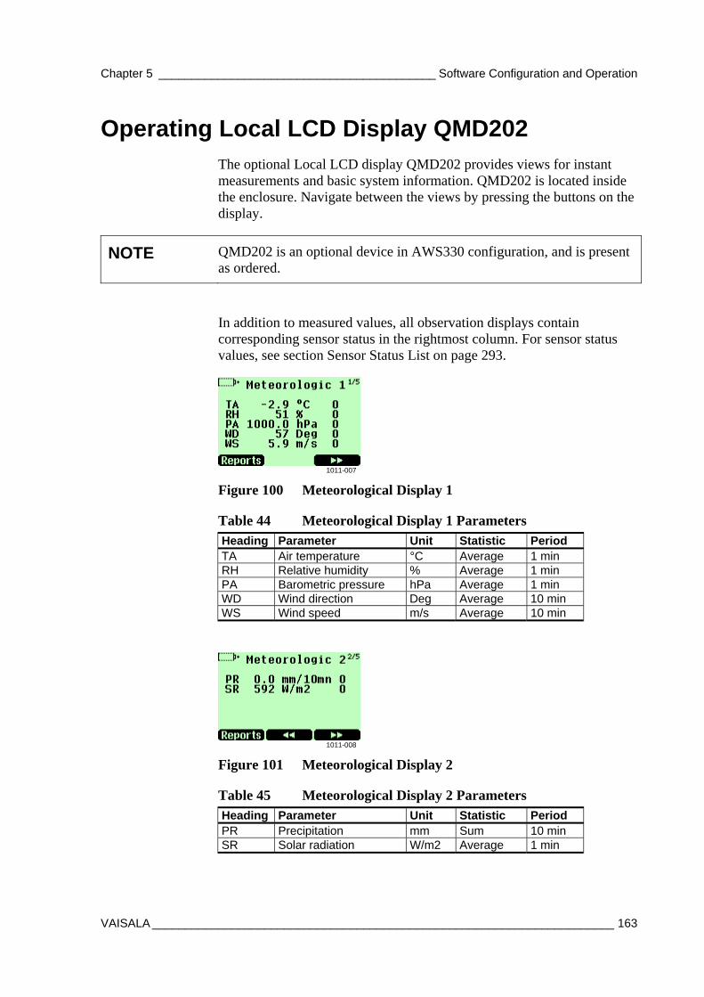
Chapter 5 __________________________________________ Software Configuration and Operation
VAISALA ______________________________________________________________________ 163
Operating Local LCD Display QMD202 The optional Local LCD display QMD202 provides views for instant measurements and basic system information. QMD202 is located inside the enclosure. Navigate between the views by pressing the buttons on the display.
NOTE QMD202 is an optional device in AWS330 configuration, and is present as ordered.
In addition to measured values, all observation displays contain corresponding sensor status in the rightmost column. For sensor status values, see section Sensor Status List on page 293.
1011-007
Figure 100 Meteorological Display 1
Table 44 Meteorological Display 1 Parameters Heading Parameter Unit Statistic Period TA Air temperature °C Average 1 min RH Relative humidity % Average 1 min PA Barometric pressure hPa Average 1 min WD Wind direction Deg Average 10 min WS Wind speed m/s Average 10 min
1011-008
Figure 101 Meteorological Display 2
Table 45 Meteorological Display 2 Parameters Heading Parameter Unit Statistic Period PR Precipitation mm Sum 10 min SR Solar radiation W/m2 Average 1 min
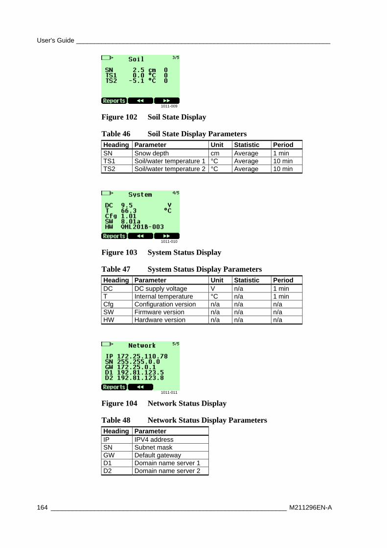
User's Guide ______________________________________________________________________
164 _________________________________________________________________ M211296EN-A
1011-009
Figure 102 Soil State Display
Table 46 Soil State Display Parameters Heading Parameter Unit Statistic Period SN Snow depth cm Average 1 min TS1 Soil/water temperature 1 °C Average 10 min TS2 Soil/water temperature 2 °C Average 10 min
1011-010
Figure 103 System Status Display
Table 47 System Status Display Parameters Heading Parameter Unit Statistic Period DC DC supply voltage V n/a 1 min T Internal temperature °C n/a 1 min Cfg Configuration version n/a n/a n/a SW Firmware version n/a n/a n/a HW Hardware version n/a n/a n/a
1011-011
Figure 104 Network Status Display
Table 48 Network Status Display Parameters Heading Parameter IP IPV4 address SN Subnet mask GW Default gateway D1 Domain name server 1 D2 Domain name server 2
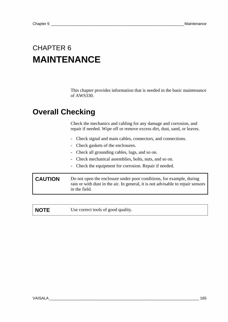
Chapter 6 ______________________________________________________________ Maintenance
VAISALA ______________________________________________________________________ 165
CHAPTER 6
MAINTENANCE
This chapter provides information that is needed in the basic maintenance of AWS330.
Overall Checking Check the mechanics and cabling for any damage and corrosion, and repair if needed. Wipe off or remove excess dirt, dust, sand, or leaves.
- Check signal and main cables, connectors, and connections.
- Check gaskets of the enclosures.
- Check all grounding cables, lugs, and so on.
- Check mechanical assemblies, bolts, nuts, and so on.
- Check the equipment for corrosion. Repair if needed.
CAUTION Do not open the enclosure under poor conditions, for example, during rain or with dust in the air. In general, it is not advisable to repair sensors in the field.
NOTE Use correct tools of good quality.
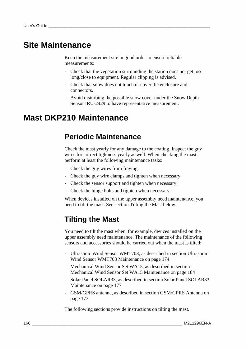
User's Guide ______________________________________________________________________
166 _________________________________________________________________ M211296EN-A
Site Maintenance Keep the measurement site in good order to ensure reliable measurements:
- Check that the vegetation surrounding the station does not get too long/close to equipment. Regular clipping is advised.
- Check that snow does not touch or cover the enclosure and connectors.
- Avoid disturbing the possible snow cover under the Snow Depth Sensor IRU-2429 to have representative measurement.
Mast DKP210 Maintenance
Periodic Maintenance
Check the mast yearly for any damage to the coating. Inspect the guy wires for correct tightness yearly as well. When checking the mast, perform at least the following maintenance tasks:
- Check the guy wires from fraying.
- Check the guy wire clamps and tighten when necessary.
- Check the sensor support and tighten when necessary.
- Check the hinge bolts and tighten when necessary.
When devices installed on the upper assembly need maintenance, you need to tilt the mast. See section Tilting the Mast below.
Tilting the Mast
You need to tilt the mast when, for example, devices installed on the upper assembly need maintenance. The maintenance of the following sensors and accessories should be carried out when the mast is tilted:
- Ultrasonic Wind Sensor WMT703, as described in section Ultrasonic Wind Sensor WMT703 Maintenance on page 174
- Mechanical Wind Sensor Set WA15, as described in section Mechanical Wind Sensor Set WA15 Maintenance on page 184
- Solar Panel SOLAR33, as described in section Solar Panel SOLAR33 Maintenance on page 177
- GSM/GPRS antenna, as described in section GSM/GPRS Antenna on page 173
The following sections provide instructions on tilting the mast.
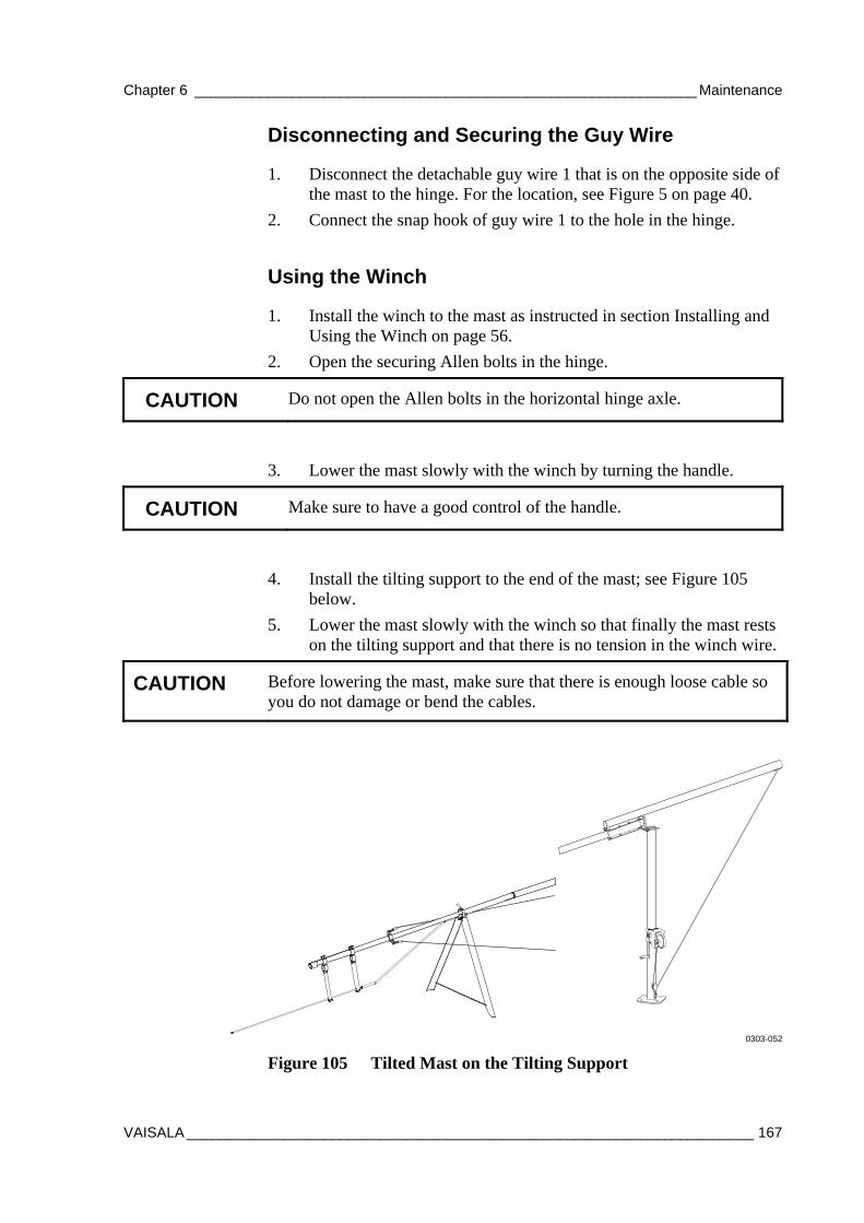
Chapter 6 ______________________________________________________________ Maintenance
VAISALA ______________________________________________________________________ 167
Disconnecting and Securing the Guy Wire
1. Disconnect the detachable guy wire 1 that is on the opposite side of the mast to the hinge. For the location, see Figure 5 on page 40.
2. Connect the snap hook of guy wire 1 to the hole in the hinge.
Using the Winch
1. Install the winch to the mast as instructed in section Installing and Using the Winch on page 56.
2. Open the securing Allen bolts in the hinge.
CAUTION Do not open the Allen bolts in the horizontal hinge axle.
3. Lower the mast slowly with the winch by turning the handle.
CAUTION Make sure to have a good control of the handle.
4. Install the tilting support to the end of the mast; see Figure 105 below.
5. Lower the mast slowly with the winch so that finally the mast rests on the tilting support and that there is no tension in the winch wire.
CAUTION Before lowering the mast, make sure that there is enough loose cable so you do not damage or bend the cables.
0303-052
Figure 105 Tilted Mast on the Tilting Support
User's Guide ______________________________________________________________________
168 _________________________________________________________________ M211296EN-A
Erecting the Mast
To erect the mast after maintenance operations, refer to the section Erecting Mast DKP210 on page 56.
CAUTION When erecting the mast, make sure that cables do not get damaged by the hinge.
Sensor Support Maintenance
When you check the mast, check that the sensor support is firmly attached. Check that the alignment is level with a spirit level.
Chapter 6 ______________________________________________________________ Maintenance
VAISALA ______________________________________________________________________ 169
Enclosure Maintenance
Visual Checking
The enclosure requires only a minimal amount of maintenance. Every six months, check that all screws of the mounting clamps are firmly tightened . Check also that the door gasket is undamaged. See also that the bottom connectors are not corroded and that they open easily. You can apply appropriate anti-corrosive/lubricant spray if required.
NOTE After a heavy storm, open the enclosure door and check for any water leakage or other damage.
Cleaning
- Check and clean the connectors from, for example, spider web.
- Check that the door is firmly closed.
- Check inside the enclosure for spider webs or other dirt.
- Check and clean the static pressure head; see location of the static pressure head in Figure 53 on page 97.
User's Guide ______________________________________________________________________
170 _________________________________________________________________ M211296EN-A
Inside Enclosure Maintenance
Checking Battery
Battery status should be checked every 3 months. This is done either using a multi-meter on the batteries' plus and minus ends, or by pressing the QBR101 battery charger. Press the QBR101C battery charger status button to see the battery status and if the system has any power (AC(mains)/battery):
- If the LED is green, the battery is OK.
- If the LED is yellow, the battery voltage is low (charge <11.5 V).
- If the LED is red, the battery is empty (charge <10 V).
If the battery status is red even after charging for a while, the battery is old and needs to be replaced. The lead acid battery may age in 3 to 5 years and needs to be replaced with a new one.
Pressure Sensor BARO-1
Periodic Maintenance
Under normal operating conditions, BARO-1 needs only a minimal amount of maintenance.
- Keep the pressure port clean. Check the pressure port every time when visiting the site.
- Annually, compare pressure values against a calibrated portable standard.
Chapter 6 ______________________________________________________________ Maintenance
VAISALA ______________________________________________________________________ 171
Field Check
NOTE Calibrating Pressure Sensor BARO-1 is a demanding, high-precision task that requires proper facilities. It is recommended that you have the sensor calibrated at Vaisala.
The AWS Client software provides means for one-point field check of the BARO-1 sensor.
Required equipment:
- Laptop PC with AWS Client software
- Traveling standard barometer (for example, Vaisala PTB330TS)
- Maintenance cable (included in the AWS330 delivery)
Field check procedure:
1. Establish terminal connection to AWS330 by connecting the maintenance cable to the COM0 port of AWS330 and to an available I/O port on your PC.
2. Lift the reference barometer to the same height as the pressure port.
NOTE Make sure that the wind does not interfere with the reading of the reference barometer.
3. Read the reference barometer reading.
4. Give this reference reading to AWS330:
- Type: BARO1CAL1003.7 (reference reading 1003.7 hPa).
5. Check the readings given by AWS330:
- Value = Reference reading
- Measured value = Measured by AWS330
- Offset = Measured value - reference reading
6. Repeat the calibration if necessary.
7. Close the terminal connection by giving the close command.
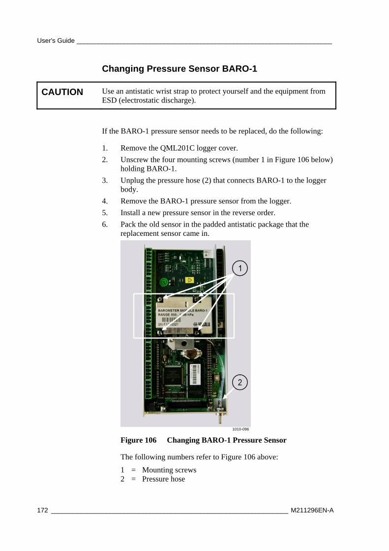
User's Guide ______________________________________________________________________
172 _________________________________________________________________ M211296EN-A
Changing Pressure Sensor BARO-1
CAUTION Use an antistatic wrist strap to protect yourself and the equipment from ESD (electrostatic discharge).
If the BARO-1 pressure sensor needs to be replaced, do the following:
1. Remove the QML201C logger cover.
2. Unscrew the four mounting screws (number 1 in Figure 106 below) holding BARO-1.
3. Unplug the pressure hose (2) that connects BARO-1 to the logger body.
4. Remove the BARO-1 pressure sensor from the logger.
5. Install a new pressure sensor in the reverse order.
6. Pack the old sensor in the padded antistatic package that the replacement sensor came in.
1010-096
Figure 106 Changing BARO-1 Pressure Sensor
The following numbers refer to Figure 106 above:
1 = Mounting screws 2 = Pressure hose
Chapter 6 ______________________________________________________________ Maintenance
VAISALA ______________________________________________________________________ 173
GSM/GPRS Antenna Maintenance The antenna requires minimal amount of maintenance. Field repairs are accomplished by changing the complete antenna.
AC (Mains) Power Supply Unit Maintenance The AC (mains) power supply unit requires a minimal amount of maintenance. Field repairs are accomplished by changing the complete module.
WARNING All electrical installations must be carried by licensed experts. The power supply unit transmits electric voltages up to 230 volts.
WARNING Do not open the AC (mains) power supply unit.
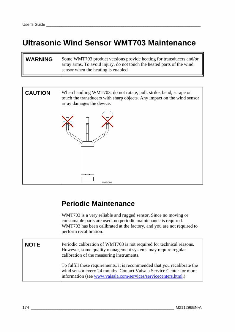
User's Guide ______________________________________________________________________
174 _________________________________________________________________ M211296EN-A
Ultrasonic Wind Sensor WMT703 Maintenance
WARNING Some WMT703 product versions provide heating for transducers and/or array arms. To avoid injury, do not touch the heated parts of the wind sensor when the heating is enabled.
CAUTION When handling WMT703, do not rotate, pull, strike, bend, scrape or touch the transducers with sharp objects. Any impact on the wind sensor array damages the device.
1005-004
Periodic Maintenance
WMT703 is a very reliable and rugged sensor. Since no moving or consumable parts are used, no periodic maintenance is required. WMT703 has been calibrated at the factory, and you are not required to perform recalibration.
NOTE Periodic calibration of WMT703 is not required for technical reasons. However, some quality management systems may require regular calibration of the measuring instruments.
To fulfill these requirements, it is recommended that you recalibrate the wind sensor every 24 months. Contact Vaisala Service Center for more information (see www.vaisala.com/services/servicecenters.html.).
Chapter 6 ______________________________________________________________ Maintenance
VAISALA ______________________________________________________________________ 175
Visual Inspection
It is recommended that you carry out a yearly visual inspection of the wind sensor to ensure correct operation and clean the wind sensor if it becomes contaminated. If necessary, you can also test the operation of WMT700 with an optional verifier, which is a small echo-free chamber.
If any of the transducers have been bent, twisted or rotated, the measurement results might not be accurate.
To avoid errors caused by damaged array, check the following:
- Array has not been hit or bent. All transducers must be parallel to each other.
- Transducers have not been scraped or touched with sharp objects. The silicon rubber transducer sleeve must be undamaged.
Cleaning
Regular cleaning of WMT703 is not required. If the wind sensor becomes contaminated, you can clean it with a soft cloth moistened with some mild detergent. Do not use solvents or a pressure washer to clean WMT703, since they may damage the silicon rubber transducer sleeve.
Testing Proper Operation
WMT703 measures how long it takes for an ultrasonic signal to travel from one transducer to receiver. Therefore, the accuracy of the sensor depends on the distance between the transducers and the time-of-flight measurement circuit, which uses a crystal oscillator for its time reference.
If necessary, you can verify the distance between the transducer arms with the optional verifier. You can order the verifier from Vaisala as an accessory (order code: WMT70VERIFIER).
It is recommended that you perform the test every 12 months or if you suspect that the transducers may have been damaged. The test can be performed either in the field or in a laboratory. Do not perform the test when the wind speed is more than 10 m/s or when there is a risk of thunderstorm in the area.
NOTE Disable heating before performing the verifier test. You can do this either by disconnecting the heater supply voltage or by setting the heaterOn parameter to 0.
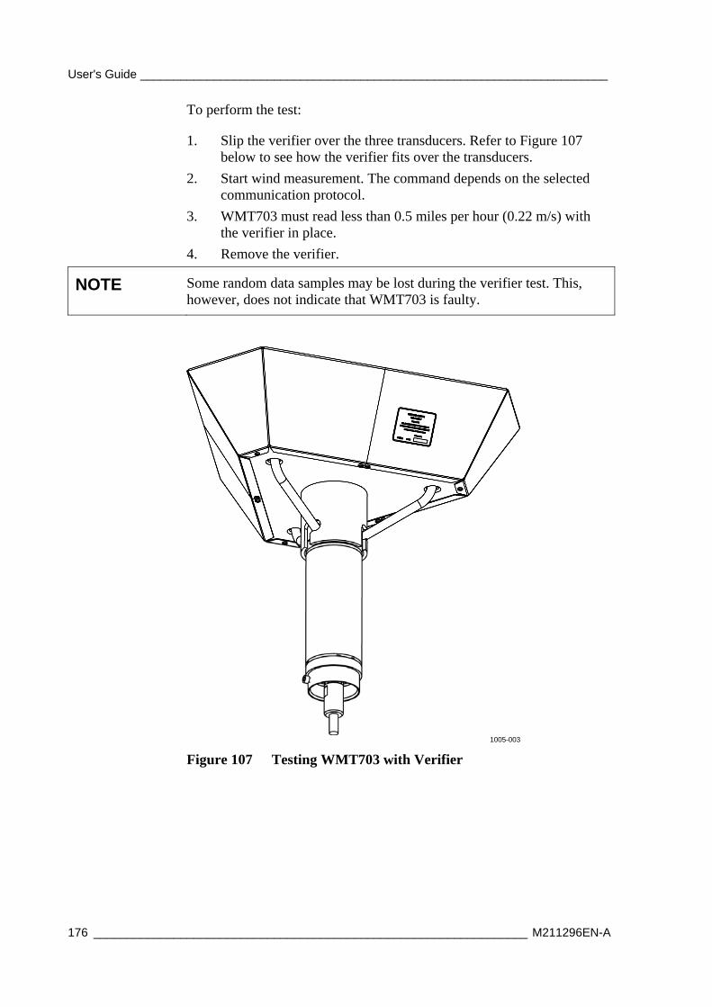
User's Guide ______________________________________________________________________
176 _________________________________________________________________ M211296EN-A
To perform the test:
1. Slip the verifier over the three transducers. Refer to Figure 107 below to see how the verifier fits over the transducers.
2. Start wind measurement. The command depends on the selected communication protocol.
3. WMT703 must read less than 0.5 miles per hour (0.22 m/s) with the verifier in place.
4. Remove the verifier.
NOTE Some random data samples may be lost during the verifier test. This, however, does not indicate that WMT703 is faulty.
1005-003
Figure 107 Testing WMT703 with Verifier
Chapter 6 ______________________________________________________________ Maintenance
VAISALA ______________________________________________________________________ 177
Snow Depth Sensor IRU-9429
Periodic Maintenance
Every month, check that the sensor alignment is correct and the sensor is firmly mounted. Check sensor operation if there is a reason to believe that the readings are erroneous or you receive a sensor status alarm. Check the sensor reading by measuring the depth of the snow with a ruler and comparing it with the reading given by the sensor. Clean the sensor from any dirt, spider webs, and so on with a lint-free cloth using water and mild detergent or alcohol.
Solar Panel SOLAR33 Maintenance
Periodic Maintenance
WARNING Wear rubber gloves to protect yourself against possible electric shock.
CAUTION Do not use a scrub brush; it can damage the module front surface.
Inspect the module at least twice a year for overall integrity. Make sure that connections to the battery are tight and free of corrosion.
Dirt accumulation on the module's front surface can reduce the light energy collected by the module. If the module surface is dirty, gently clean it with a soft cloth or sponge using water and a mild detergent.
User's Guide ______________________________________________________________________
178 _________________________________________________________________ M211296EN-A
Air Temperature and Relative Humidity Probe HMP155 Maintenance
Visual Check
Every three months, check that the temperature and humidity probe mounting is secured and that the cable is in good condition.
Cleaning
Clean the probe with a soft, lint-free cloth moistened with mild detergent.
Changing the Probe Filter
Every six months, change the probe filter:
NOTE Depending on the conditions of the measurement site, such as air pollution and dust, the probe filter may need to be changed more frequently.
NOTE When handling the probe, do not touch the sensor heads (numbers 3 and 4 in Figure 108 on page 179).
1. Remove the probe from inside the radiation shield.
1. Carefully remove the filter from the probe: screw it counter-clockwise, the pull it out without touching the sensor heads.
2. After removing the filter, check the O-ring and change it if necessary. See Figure 108 on page 179. Do not touch the sensor heads.
3. Without delay, install the new filter carefully on the probe without touching the sensor heads.
New filters can be ordered from Vaisala (order code: 219452SP, includes sintered Teflon filter and O-ring).
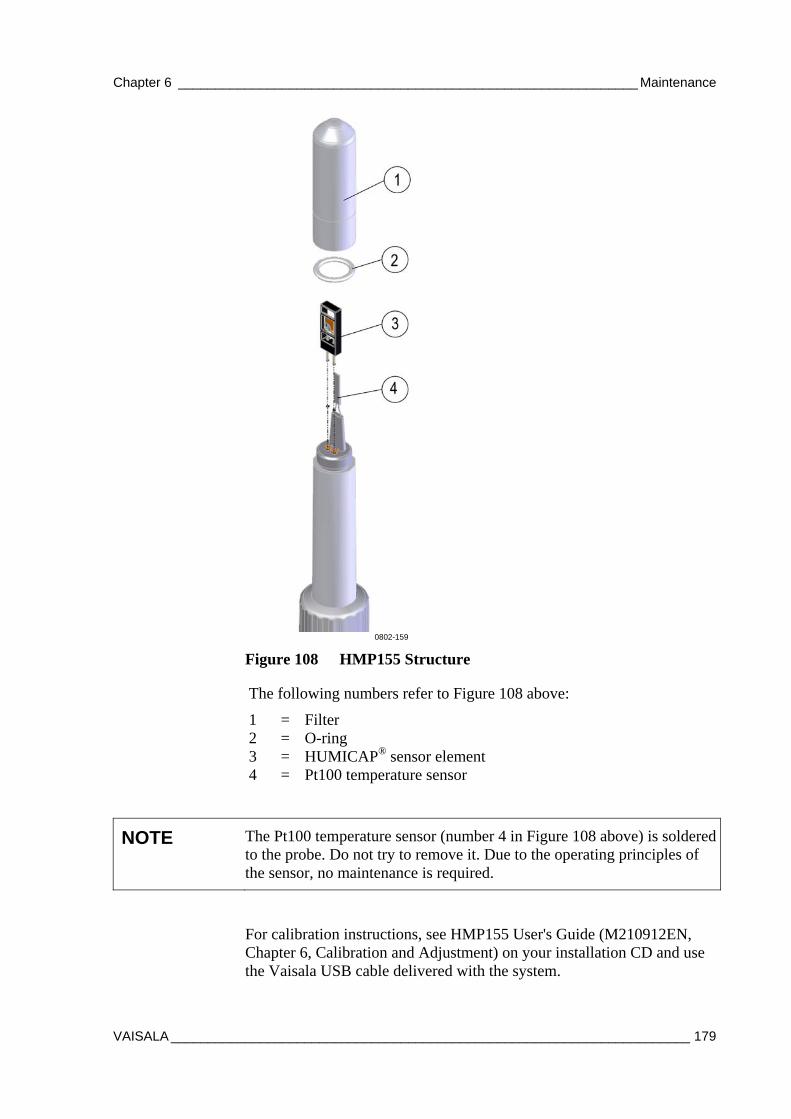
Chapter 6 ______________________________________________________________ Maintenance
VAISALA ______________________________________________________________________ 179
0802-159
Figure 108 HMP155 Structure
The following numbers refer to Figure 108 above:
1 = Filter 2 = O-ring 3 = HUMICAP® sensor element 4 = Pt100 temperature sensor
NOTE The Pt100 temperature sensor (number 4 in Figure 108 above) is soldered to the probe. Do not try to remove it. Due to the operating principles of the sensor, no maintenance is required.
For calibration instructions, see HMP155 User's Guide (M210912EN, Chapter 6, Calibration and Adjustment) on your installation CD and use the Vaisala USB cable delivered with the system.
User's Guide ______________________________________________________________________
180 _________________________________________________________________ M211296EN-A
Sending for Calibration
Every 12 months, send HMP155 to Vaisala for calibration and replace it with a calibrated spare probe:
1. Remove the old probe from inside the radiation shield.
2. Check the operation of the new probe by warming the sensor head with your hand, and monitor the value change.
3. Place the new probe inside the radiation shield.
4. Send the old probe to Vaisala for calibration.
Or, if a calibrated spare probe is not available, do the following:
1. Send the probe to Vaisala for calibration.
2. When the calibrated sensor arrives from Vaisala, check the operation of the probe by warming the sensor head with your hand, and monitor the value change.
3. Place the probe inside the radiation shield.
Calibration must always be done when there is reason to believe that the device is not within the accuracy specifications.
Changing HMP155
Contact Vaisala to replace HMP155.
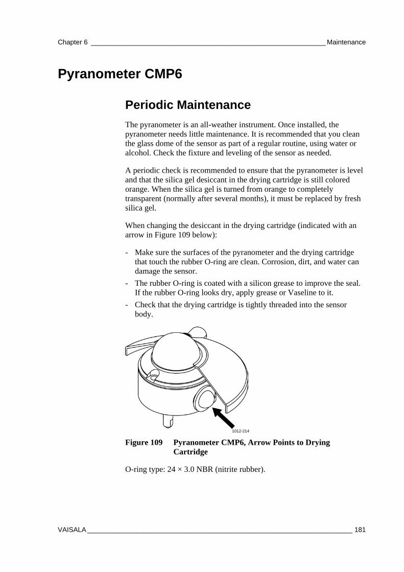
Chapter 6 ______________________________________________________________ Maintenance
VAISALA ______________________________________________________________________ 181
Pyranometer CMP6
Periodic Maintenance
The pyranometer is an all-weather instrument. Once installed, the pyranometer needs little maintenance. It is recommended that you clean the glass dome of the sensor as part of a regular routine, using water or alcohol. Check the fixture and leveling of the sensor as needed.
A periodic check is recommended to ensure that the pyranometer is level and that the silica gel desiccant in the drying cartridge is still colored orange. When the silica gel is turned from orange to completely transparent (normally after several months), it must be replaced by fresh silica gel.
When changing the desiccant in the drying cartridge (indicated with an arrow in Figure 109 below):
- Make sure the surfaces of the pyranometer and the drying cartridge that touch the rubber O-ring are clean. Corrosion, dirt, and water can damage the sensor.
- The rubber O-ring is coated with a silicon grease to improve the seal. If the rubber O-ring looks dry, apply grease or Vaseline to it.
- Check that the drying cartridge is tightly threaded into the sensor body.
1012-214
Figure 109 Pyranometer CMP6, Arrow Points to Drying Cartridge
O-ring type: 24 × 3.0 NBR (nitrite rubber).
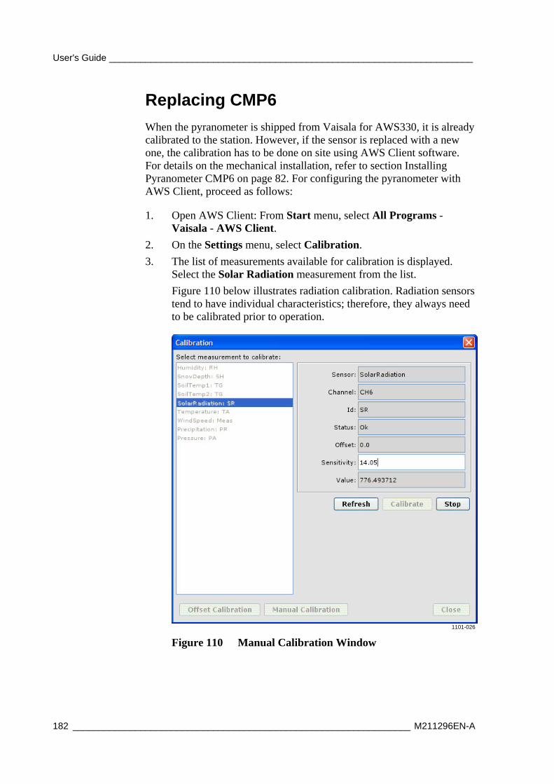
User's Guide ______________________________________________________________________
182 _________________________________________________________________ M211296EN-A
Replacing CMP6
When the pyranometer is shipped from Vaisala for AWS330, it is already calibrated to the station. However, if the sensor is replaced with a new one, the calibration has to be done on site using AWS Client software. For details on the mechanical installation, refer to section Installing Pyranometer CMP6 on page 82. For configuring the pyranometer with AWS Client, proceed as follows:
1. Open AWS Client: From Start menu, select All Programs - Vaisala - AWS Client.
2. On the Settings menu, select Calibration.
3. The list of measurements available for calibration is displayed. Select the Solar Radiation measurement from the list.
Figure 110 below illustrates radiation calibration. Radiation sensors tend to have individual characteristics; therefore, they always need to be calibrated prior to operation.
1101-026
Figure 110 Manual Calibration Window
Chapter 6 ______________________________________________________________ Maintenance
VAISALA ______________________________________________________________________ 183
4. The Factor parameter has sensor-dependent use. It affects the gain of the measurement or the sensitivity of the radiation sensor. To calibrate radiation, enter the sensor-dependent sensitivity factor [V/Wm-2], which is given in the type sticker or the calibration sheet of the particular sensor.
5. Calibrate the sensor by selecting Calibrate.
NOTE New sensor calibration values are taken into use in the QML logger after a reset with, for example, the Reset command. For further information on resetting the QML logger, see section Resetting the QML Logger on page 162.
Soil Temperature Sensor QMT110
Visual Checking
Check the connectors yearly. Check that the visible cable on the ground is in good shape.
The QMT110 sensor does not need any regular maintenance. Field repairs are accomplished by replacing the complete sensor. When the QMT110 sensor is extracted, clean the dirt accumulation on the sensor surface with a soft cloth or sponge using water and mild detergent. Field repairs are accomplished by replacing the complete sensor.
User's Guide ______________________________________________________________________
184 _________________________________________________________________ M211296EN-A
Mechanical Wind Sensor Set WA15 Maintenance
Periodic Maintenance
Replace the bearings yearly and check that the printed circuit board is not corroded. Check operation whenever you tilt the mast.
Cleaning
Heavy contamination in the vane, such as bird droplets or ice will deteriorate the accuracy of the wind vane. Clean the vane when necessary.
Testing Proper Operation
The sensor will hold its accuracy in all conditions for 1 year. If the rains are mostly casual and moderate, and the atmospheric corrosion is typical, the sensor accuracy will remain for 2 years.
However, the ball bearings must be checked once a year and the sensor shaft rotated manually. To do this, remove the vane assembly. To ensure proper operation, the shaft should spin smoothly and it should not create any detectable noise.
Replacing Bearings of WAV151
Replacement of the bearings should only be done by a trained technician. To replace the ball bearings, follow the procedure below and refer to Figure 111 on page 187 or send the wind set to Vaisala for maintenance.
1. Open the vane assembly fixing screw with a 2-mm Allen key. The correct screw is the lower one shown in Figure 111 on page 187. Remove the assembly.
CAUTION The vane assembly fixing screw has been treated with sealant. Do not remove the fixing screw to ensure perfect sealing.
2. Loosen the hex nut of the connector with a 27-mm tool.
Chapter 6 ______________________________________________________________ Maintenance
VAISALA ______________________________________________________________________ 185
CAUTION Be careful not to bend the connector pins.
3. Loosen the three pan head screws at the bottom of the sensor body with a 7-mm tool.
4. Remove the lower body assembly by pulling it straight outwards.
5. Loosen the spacer screws with a 7-mm tool and disconnect the heating element outlet.
6. Remove the printed circuit board.
CAUTION Do not twist or bend the connector. This may break the pins.
7. Loosen the fixing screw of the code disc with a 2-mm Allen key and remove the disc.
8. Remove the external retaining ring (using narrow-pointed pliers).
9. Remove the spacer ring.
10. Remove the internal retaining ring at the bottom of the shaft (using narrow-pointed pliers).
11. Remove the lower bearing.
12. Push out the shaft downwards through the upper body.
13. Remove the top bearing.
To reassemble the sensor, reverse the earlier work order.
1. Take the previous steps in reverse order until assembling the code disc.
NOTE Be careful when handling the new ball bearings. Do not drop them or force them onto the shaft.
2. Attach the code disc (number 7 in Figure 111 on page 187) back onto the shaft. The disc has to be positioned so that it does not touch the opto-coupler on the printed circuit board (6). Tighten the fixing screw of the code disc.
CAUTION Make sure that the code disc does not touch the opto-coupler.
3. Attach the heating element outlet to the printed circuit board. Put the printed circuit board in place and fasten it with spacers (5).
User's Guide ______________________________________________________________________
186 _________________________________________________________________ M211296EN-A
4. Put the lower body assembly (4) carefully into place. Fasten the three screws (3) at the bottom of the sensor. Make sure that the bigger O-ring (14) is correctly positioned between the upper and the lower sensor bodies. Check also that the connector O-ring (14) is in place. The O-ring is recommended to be replaced with a new one after each opening.
NOTE When placing the lower body assembly, make sure that the O-ring is correctly positioned between the upper and lower bodies. It is recommended to replace the O-rings with new ones before reassembling.
5. Tighten the hex nut of the connector (2).
6. Connect the cable plug to the sensor body connector. Fasten the sensor body on the cross arm with three screws.
7. Mount the vane assembly onto the sensor body. Tighten the screw.
CAUTION The heating resistance element cannot be removed without special tools. To avoid any damage, it is recommended that replacement of the heating element be carried out by a trained technician.
The following numbers refer to Figure 111 on page 187:
1 = Vane assembly 2 = Hex nut of the connector 3 = M6 x 16 DIN7991 (3 pcs) 4 = Lower body 5 = Spacer (3 pcs) 6 = Printed circuit board (PCB) 7 = Code disc 8 = External retaining ring, body 9 = Spacer 10 = Internal retaining ring, shaft 11 = Ball bearings 12 = Shaft and Upper body assembly 13 = Ball bearings 14 = O-rings, 2 pcs
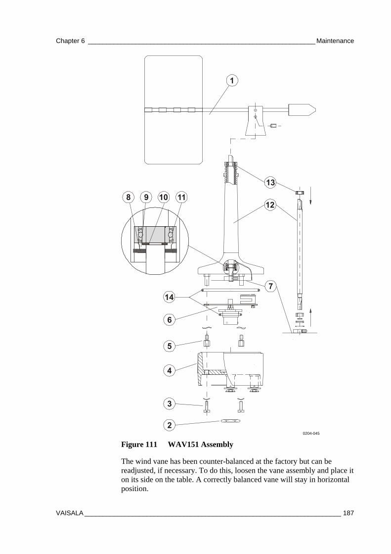
Chapter 6 ______________________________________________________________ Maintenance
VAISALA ______________________________________________________________________ 187
0204-045
Figure 111 WAV151 Assembly
The wind vane has been counter-balanced at the factory but can be readjusted, if necessary. To do this, loosen the vane assembly and place it on its side on the table. A correctly balanced vane will stay in horizontal position.
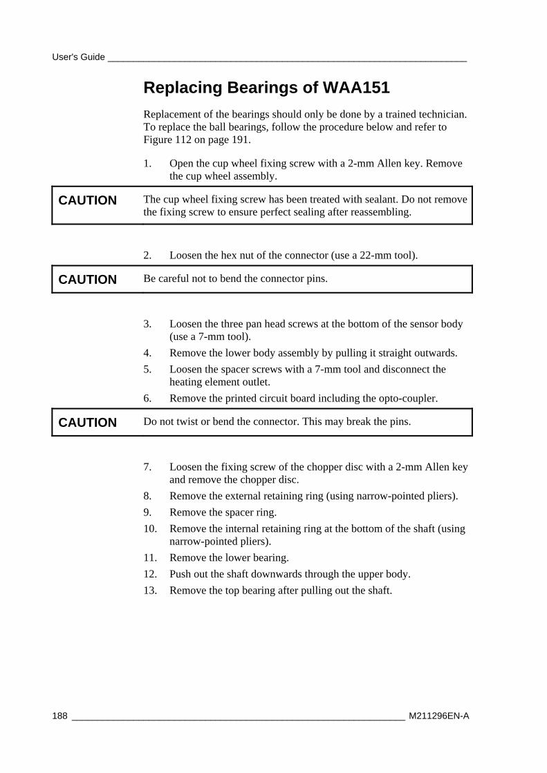
User's Guide ______________________________________________________________________
188 _________________________________________________________________ M211296EN-A
Replacing Bearings of WAA151
Replacement of the bearings should only be done by a trained technician. To replace the ball bearings, follow the procedure below and refer to Figure 112 on page 191.
1. Open the cup wheel fixing screw with a 2-mm Allen key. Remove the cup wheel assembly.
CAUTION The cup wheel fixing screw has been treated with sealant. Do not remove the fixing screw to ensure perfect sealing after reassembling.
2. Loosen the hex nut of the connector (use a 22-mm tool).
CAUTION Be careful not to bend the connector pins.
3. Loosen the three pan head screws at the bottom of the sensor body (use a 7-mm tool).
4. Remove the lower body assembly by pulling it straight outwards.
5. Loosen the spacer screws with a 7-mm tool and disconnect the heating element outlet.
6. Remove the printed circuit board including the opto-coupler.
CAUTION Do not twist or bend the connector. This may break the pins.
7. Loosen the fixing screw of the chopper disc with a 2-mm Allen key and remove the chopper disc.
8. Remove the external retaining ring (using narrow-pointed pliers).
9. Remove the spacer ring.
10. Remove the internal retaining ring at the bottom of the shaft (using narrow-pointed pliers).
11. Remove the lower bearing.
12. Push out the shaft downwards through the upper body.
13. Remove the top bearing after pulling out the shaft.
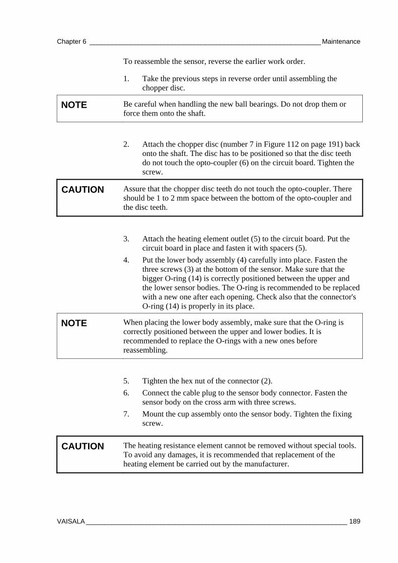
Chapter 6 ______________________________________________________________ Maintenance
VAISALA ______________________________________________________________________ 189
To reassemble the sensor, reverse the earlier work order.
1. Take the previous steps in reverse order until assembling the chopper disc.
NOTE Be careful when handling the new ball bearings. Do not drop them or force them onto the shaft.
2. Attach the chopper disc (number 7 in Figure 112 on page 191) back onto the shaft. The disc has to be positioned so that the disc teeth do not touch the opto-coupler (6) on the circuit board. Tighten the screw.
CAUTION Assure that the chopper disc teeth do not touch the opto-coupler. There should be 1 to 2 mm space between the bottom of the opto-coupler and the disc teeth.
3. Attach the heating element outlet (5) to the circuit board. Put the circuit board in place and fasten it with spacers (5).
4. Put the lower body assembly (4) carefully into place. Fasten the three screws (3) at the bottom of the sensor. Make sure that the bigger O-ring (14) is correctly positioned between the upper and the lower sensor bodies. The O-ring is recommended to be replaced with a new one after each opening. Check also that the connector's O-ring (14) is properly in its place.
NOTE When placing the lower body assembly, make sure that the O-ring is correctly positioned between the upper and lower bodies. It is recommended to replace the O-rings with a new ones before reassembling.
5. Tighten the hex nut of the connector (2).
6. Connect the cable plug to the sensor body connector. Fasten the sensor body on the cross arm with three screws.
7. Mount the cup assembly onto the sensor body. Tighten the fixing screw.
CAUTION The heating resistance element cannot be removed without special tools. To avoid any damages, it is recommended that replacement of the heating element be carried out by the manufacturer.
User's Guide ______________________________________________________________________
190 _________________________________________________________________ M211296EN-A
The following numbers refer to Figure 112 on page 191:
1 = Cup wheel assembly 2 = Hex nut of the connector 3 = M6x16 DIN7991 (3 pcs) 4 = Lower body 5 = Spacer (3 pcs) 6 = Printed circuit board (PCB) 7 = Chopper disc 8 = External retaining ring, body 9 = Spacer ring 10 = Internal retaining ring, shaft 11 = Ball bearings 12 = Shaft and Upper body assembly 13 = Ball bearings 14 = O-rings, 2 pcs
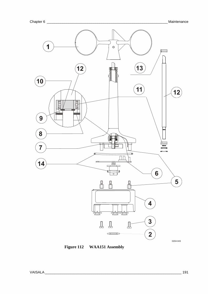
Chapter 6 ______________________________________________________________ Maintenance
VAISALA ______________________________________________________________________ 191
0204-043
Figure 112 WAA151 Assembly
User's Guide ______________________________________________________________________
192 _________________________________________________________________ M211296EN-A
Rain Gauge RG13(H) Maintenance
Periodic Maintenance
Check Rain Gauge RG13(H) once a week. In the fall, or when leaves are falling and there is a lot of debris in circulation, it is recommended that you check the sensor daily or, at minimum, once a week.
NOTE If the gauge is connected to the QML data logger and the data logger is operating, avoid tipping the cup assembly to avoid erroneous measurements.
- Inspect the funnel and filter for any damage or blockage. Remove any obstacles from the funnel, such as accumulated leaves, debris, dirt and dust. Clean the filter by removing the end cap from the filter tube.
- Yearly, remove the filter material carefully, clean and replace the filter and the cap.
- Once or twice a year, clean the spoon from dust and dirt once or twice a year to ensure precise measuring. Remove and clean any dirt from the bucket.
- Check that the gauge is still level. It is surprisingly easy for an apparently immovable gauge to become tilted as a result of small ground movements or vandalism.
If the rain gauge is disconnected from the logger or does not log data, it is a good idea to check the balance arm of the bucket for stiffness. The easiest way to do this in the field is to try to balance the bucket in its center position; doing this should be very difficult (if not impossible). If the bucket balances easily, examine the bucket closely for any dirt or wear on the pivot pin and bucket tubes.
Chapter 6 ______________________________________________________________ Maintenance
VAISALA ______________________________________________________________________ 193
Replacing Components In some overvoltage conditions, such as the case of a lightning strike, some protective components might get damaged and need replacement. To replace other components than the ones described here or in the previous sections, contact Vaisala.
Changing Battery
1. Turn the power off from the main switch.
2. Unplug the battery wires.
3. Unscrew the screw holding the battery clamp around the battery.
4. Slide the clamp to the left.
5. Remove the battery.
6. Install a new battery in reverse order.
Changing the QML201 Logger
NOTE This should only be done by a trained technician.
1. Turn the power off from the main switch.
2. Unplug the logger connectors. You might need to cut the cable ties holding the wires to have more slack in the wiring. Do this from the bottom side of the installation plate to avoid damaging the wiring.
3. Unplug the pressure tubing from the nozzle in the lower right corner of the logger.
4. Remove the logger from the DIN-rail in the installation plate by lifting from the left side of the logger bottom.
5. Install a new logger on the installation plate and connect the tubing and cabling in reverse order. Replace the cut cable ties with new ones.

User's Guide ______________________________________________________________________
194 _________________________________________________________________ M211296EN-A
Changing Communication Modules
CAUTION In general, it is not advisable to open the QML data logger cover in the field.
The communication modules of the QML201C data logger are attached to the circuit board of the logger. In case a communication module has to be replaced, remove the logger cover and the old module by pulling from the edges. Push the replacement module on the connector block MOD1 or MOD2. By default, the modules are installed as described in Table 49 below.
Table 49 Default Configuration for Communication Modules Module Connector Block Module Placement DSI486 MOD1 See Figure 113 below. DSE101 MOD2 See Figure 113 below.
CAUTION When inserting the modules, be careful not to bend the connector pins.
1005-010
Figure 113 Communication Module Placement
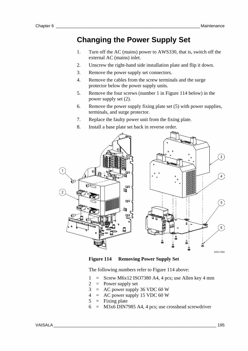
Chapter 6 ______________________________________________________________ Maintenance
VAISALA ______________________________________________________________________ 195
Changing the Power Supply Set
1. Turn off the AC (mains) power to AWS330, that is, switch off the external AC (mains) inlet.
2. Unscrew the right-hand side installation plate and flip it down.
3. Remove the power supply set connectors.
4. Remove the cables from the screw terminals and the surge protector below the power supply units.
5. Remove the four screws (number 1 in Figure 114 below) in the power supply set (2).
6. Remove the power supply fixing plate set (5) with power supplies, terminals, and surge protector.
7. Replace the faulty power unit from the fixing plate.
8. Install a base plate set back in reverse order.
1012-202
Figure 114 Removing Power Supply Set
The following numbers refer to Figure 114 above:
1 = Screw M6x12 ISO7380 A4, 4 pcs; use Allen key 4 mm 2 = Power supply set 3 = AC power supply 36 VDC 60 W 4 = AC power supply 15 VDC 60 W 5 = Fixing plate 6 = M3x6 DIN7985 A4, 4 pcs; use crosshead screwdriver
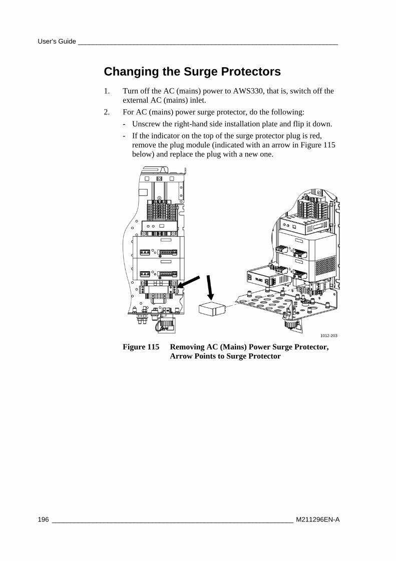
User's Guide ______________________________________________________________________
196 _________________________________________________________________ M211296EN-A
Changing the Surge Protectors
1. Turn off the AC (mains) power to AWS330, that is, switch off the external AC (mains) inlet.
2. For AC (mains) power surge protector, do the following:
- Unscrew the right-hand side installation plate and flip it down.
- If the indicator on the top of the surge protector plug is red, remove the plug module (indicated with an arrow in Figure 115 below) and replace the plug with a new one.
1012-203
Figure 115 Removing AC (Mains) Power Surge Protector, Arrow Points to Surge Protector
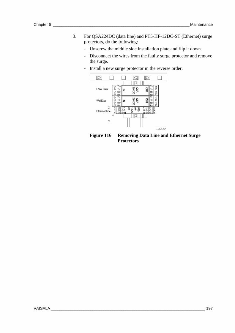
Chapter 6 ______________________________________________________________ Maintenance
VAISALA ______________________________________________________________________ 197
3. For QSA224DC (data line) and PT5-HF-12DC-ST (Ethernet) surge protectors, do the following:
- Unscrew the middle side installation plate and flip it down.
- Disconnect the wires from the faulty surge protector and remove the surge.
- Install a new surge protector in the reverse order.
1012-204
Figure 116 Removing Data Line and Ethernet Surge Protectors
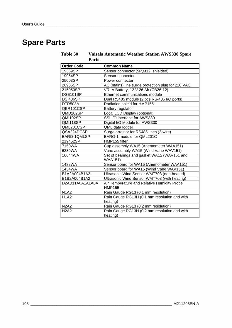
User's Guide ______________________________________________________________________
198 _________________________________________________________________ M211296EN-A
Spare Parts Table 50 Vaisala Automatic Weather Station AWS330 Spare
Parts Order Code Common Name 19369SP Sensor connector (5P,M12, shielded) 19954SP Sensor connector 25003SP Power connector 26935SP AC (mains) line surge protection plug for 220 VAC 215050SP VRLA Battery, 12 V 26 Ah (CB26-12) DSE101SP Ethernet communications module DSI486SP Dual RS485 module (2 pcs RS-485 I/O ports) DTR503A Radiation shield for HMP155 QBR101CSP Battery regulator QMD202SP Local LCD Display (optional) QMI102SP SSI I/O interface for AWS330 QMI118SP Digital I/O Module for AWS330 QML201CSP QML data logger QSA224DCSP Surge arrestor for RS485 lines (2-wire) BARO-1QMLSP BARO-1 module for QML201C 219452SP HMP155 filter 7150WA Cup assembly WA15 (Anemometer WAA151) 6389WA Vane assembly WA15 (Wind Vane WAV151) 16644WA Set of bearings and gasket WA15 (WAV151 and
WAA151) 1433WA Sensor board for WA15 (Anemometer WAA151) 1434WA Sensor board for WA15 (Wind Vane WAV151) B1A2A004B1A2 Ultrasonic Wind Sensor WMT703 (non-heated) B1B2A004B1A2 Ultrasonic Wind Sensor WMT703 (with heating) D2AB11A0A1A1A0A Air Temperature and Relative Humidity Probe
HMP155 N1A2 Rain Gauge RG13 (0.1 mm resolution) H1A2 Rain Gauge RG13H (0.1 mm resolution and with
heating) N2A2 Rain Gauge RG13 (0.2 mm resolution) H2A2 Rain Gauge RG13H (0.2 mm resolution and with
heating)
Chapter 6 ______________________________________________________________ Maintenance
VAISALA ______________________________________________________________________ 199
QML Logger QML201C Maintenance
Updating AWS330 Configuration File
AWS330 functionality is based on a configuration file that is pre-loaded to QML logger at factory. It may later become necessary to update the configuration file in the logger, for example to fix a problem or to introduce a new feature.
CAUTION Update the configuration file only when instructed by Vaisala, with a file received or downloaded from Vaisala. If the configuration file is updated otherwise, for example, by using a file modified by the end-user, Vaisala will no longer provide support for such a system free of charge.
To update the configuration file:
1. Start AWS Client.
2. Open menu Settings – Options, and make sure that option Secure Setup Upload is selected. Close the dialog by clicking the Save button.
3. On the Maintenance menu, select Setup File - Upload to Logger.
4. The Select File window is displayed as shown in Figure 117 on page 200. Select the appropriate setup file and click Select File. Note that the default folder for uploading setup files is defined in the AWS Client Options window.
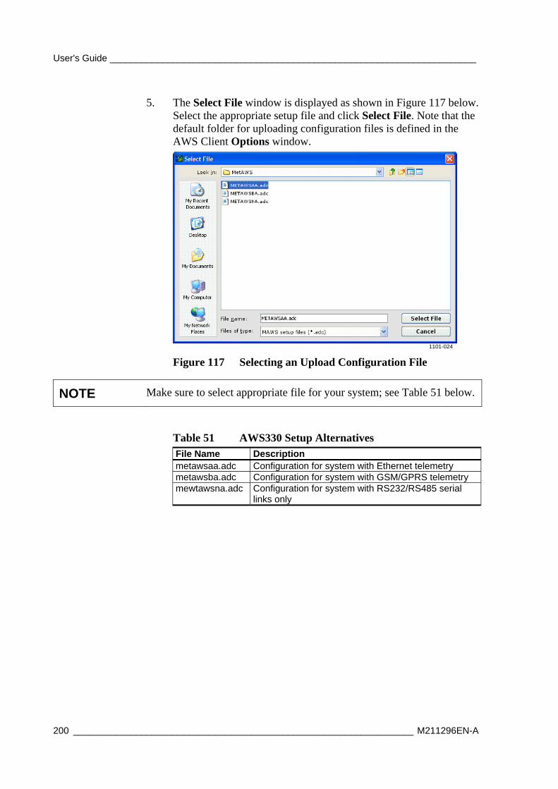
User's Guide ______________________________________________________________________
200 _________________________________________________________________ M211296EN-A
5. The Select File window is displayed as shown in Figure 117 below. Select the appropriate setup file and click Select File. Note that the default folder for uploading configuration files is defined in the AWS Client Options window.
1101-024
Figure 117 Selecting an Upload Configuration File
NOTE Make sure to select appropriate file for your system; see Table 51 below.
Table 51 AWS330 Setup Alternatives File Name Description metawsaa.adc Configuration for system with Ethernet telemetry metawsba.adc Configuration for system with GSM/GPRS telemetry mewtawsna.adc Configuration for system with RS232/RS485 serial
links only
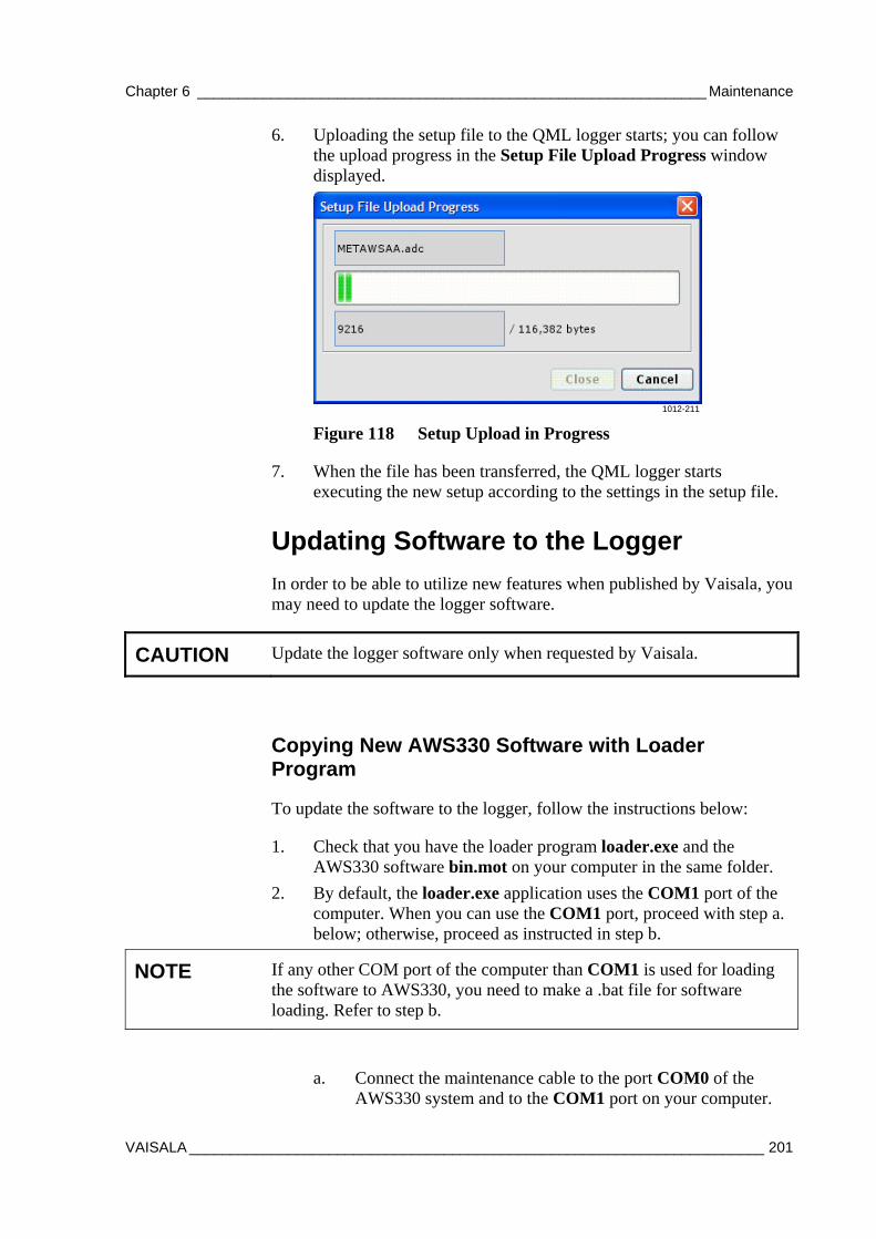
Chapter 6 ______________________________________________________________ Maintenance
VAISALA ______________________________________________________________________ 201
6. Uploading the setup file to the QML logger starts; you can follow the upload progress in the Setup File Upload Progress window displayed.
1012-211
Figure 118 Setup Upload in Progress
7. When the file has been transferred, the QML logger starts executing the new setup according to the settings in the setup file.
Updating Software to the Logger
In order to be able to utilize new features when published by Vaisala, you may need to update the logger software.
CAUTION Update the logger software only when requested by Vaisala.
Copying New AWS330 Software with Loader Program
To update the software to the logger, follow the instructions below:
1. Check that you have the loader program loader.exe and the AWS330 software bin.mot on your computer in the same folder.
2. By default, the loader.exe application uses the COM1 port of the computer. When you can use the COM1 port, proceed with step a. below; otherwise, proceed as instructed in step b.
NOTE If any other COM port of the computer than COM1 is used for loading the software to AWS330, you need to make a .bat file for software loading. Refer to step b.
a. Connect the maintenance cable to the port COM0 of the AWS330 system and to the COM1 port on your computer.
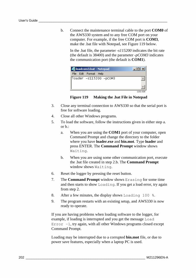
User's Guide ______________________________________________________________________
202 _________________________________________________________________ M211296EN-A
b. Connect the maintenance terminal cable to the port COM0 of the AWS330 system and to any free COM port on your computer. For example, if the free COM port is COM3, make the .bat file with Notepad, see Figure 119 below.
In the .bat file, the parameter -s115200 indicates the bit rate (the default is 38400) and the parameter -pCOM3 indicates the communication port (the default is COM1).
1101-028
Figure 119 Making the .bat File in Notepad
3. Close any terminal connection to AWS330 so that the serial port is free for software loading.
4. Close all other Windows programs.
5. To load the software, follow the instructions given in either step a. or b.:
a. When you are using the COM1 port of your computer, open Command Prompt and change the directory to the folder where you have loader.exe and bin.mot. Type loader and press ENTER. The Command Prompt window shows Waiting.
b. When you are using some other communication port, execute the .bat file created in step 2.b. The Command Prompt window shows Waiting.
6. Reset the logger by pressing the reset button.
7. The Command Prompt window shows Erasing for some time and then starts to show Loading. If you get a load error, try again from step 2.
8. After a few minutes, the display shows Loading 100 %.
9. The program restarts with an existing setup, and AWS330 is now ready to operate.
If you are having problems when loading software to the logger, for example, if loading is interrupted and you get the message Load Error -1, try again, with all other Windows programs closed except Command Prompt.
Loading may be interrupted due to a corrupted bin.mot file, or due to power save features, especially when a laptop PC is used.

Chapter 6 ______________________________________________________________ Maintenance
VAISALA ______________________________________________________________________ 203
Copying a New AWS330 Software from CF Memory Card
As an alternative for updating AWS330 software through the serial port using loader.exe you can receive a pre-programmed CF (CompactFlash) card from Vaisala including the latest software to be copied. Each time AWS330 starts up, the boot software checks if a new software is available for loading on the CF card.
To copy a new software into AWS330, proceed as follows:
1 Insert the CF card received from Vaisala into the CF card slot in the QML logger.
2. Launch copying the new software by issuing the command SWLOAD.
3. The AWS330 software checks that the boot code is valid and the CF includes Motorola's S-record at the specified address. The firmware also checks that the CF card is formatted and that there is a file on it named bin.mot.
4. When the application has been copied, the QML logger restarts automatically.
5. If SWLOAD refuses to copy the new software, the CF card does not include a valid software.
6. When the new application has been restarted, take the CF card out of the QML logger and store it for future use.

User's Guide ______________________________________________________________________
204 _________________________________________________________________ M211296EN-A
This page intentionally left blank.
Chapter 7 ___________________________________________________________ Troubleshooting
VAISALA ______________________________________________________________________ 205
CHAPTER 7
TROUBLESHOOTING
This chapter describes common problems, their probable causes and remedies, and provides contact information for technical support.
Troubleshooting QML Logger QML201C When troubleshooting the QML logger, make sure you have the tools listed in Table 52 below.
Table 52 Recommended Tools for Troubleshooting Tools List Maintenance cable and a laptop PC with the applicable versions of the setup files and the AWS Client software Keys for the enclosures Multimeter Flat head screwdrivers, especially small ones Phillips screwdrivers, especially small ones Set of open-end wrenches, different sizes Set of Allen keys Applicable spare parts, for example, a new QML logger Safety helmet when tilting the mast
User's Guide ______________________________________________________________________
206 _________________________________________________________________ M211296EN-A
Opening a Service Connection through QML Logger
For instructions on operating AWS Client, refer to Chapter 5, Software Configuration and Operation, on page 101.
The command interface of the modem or a serial sensor can be accessed through the QML logger, for example, to send the AT commands manually. To control the modem or sensor directly, first open the service connection to the logger. Then enter one of the following commands:
Table 53 Opening Connection to Devices Device Command GSM/GPRS modem open MOD1_1 Ultrasonic Wind Sensor WMT703 open COM1
To terminate this operation, type close. While the direct connection to the modem or sensor is open, any automatic operation through the connected port is blocked.
Recording Terminal Connection Text
In problem situations, you can save the commands and program responses that you see in the AWS Client terminal connection window.
To capture all the text shown in the terminal window into a file, first select Settings, then Options, then select the Trace log on option. The program starts saving all text into a file of format yyMMddHHmmSS.log, where yy stands for year, MM for month, dd for day, and so on. The file is stored in the Trace log directory you have defined in the Options window.
NOTE AWS Client software keeps recording terminal connection history until the Trace log on option is cleared. Do not neglect to clear this option once you have recorded enough messages; otherwise, log files will accumulate over time and unnecessarily reserve your disk space.
When you no longer need the capture files, you can delete them from your PC. The capture file is in format yyMMddHHmmSS.log, which name is a time stamp of the file's creation. The file is saved in the Trace log directory you have defined in the Options window.
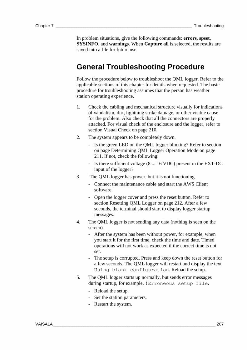
Chapter 7 ___________________________________________________________ Troubleshooting
VAISALA ______________________________________________________________________ 207
In problem situations, give the following commands: errors, spset, SYSINFO, and warnings. When Capture all is selected, the results are saved into a file for future use.
General Troubleshooting Procedure
Follow the procedure below to troubleshoot the QML logger. Refer to the applicable sections of this chapter for details when requested. The basic procedure for troubleshooting assumes that the person has weather station operating experience.
1. Check the cabling and mechanical structure visually for indications of vandalism, dirt, lightning strike damage, or other visible cause for the problem. Also check that all the connectors are properly attached. For visual check of the enclosure and the logger, refer to section Visual Check on page 210.
2. The system appears to be completely down.
- Is the green LED on the QML logger blinking? Refer to section on page Determining QML Logger Operation Mode on page 211. If not, check the following:
- Is there sufficient voltage (8 ... 16 VDC) present in the EXT-DC input of the logger?
3. The QML logger has power, but it is not functioning.
- Connect the maintenance cable and start the AWS Client software.
- Open the logger cover and press the reset button. Refer to section Resetting QML Logger on page 212. After a few seconds, the terminal should start to display logger startup messages.
4. The QML logger is not sending any data (nothing is seen on the screen). - After the system has been without power, for example, when
you start it for the first time, check the time and date. Timed operations will not work as expected if the correct time is not set.
- The setup is corrupted. Press and keep down the reset button for a few seconds. The QML logger will restart and display the text Using blank configuration. Reload the setup.
5. The QML logger starts up normally, but sends error messages during startup, for example, !Erroneous setup file.
- Reload the setup. - Set the station parameters. - Restart the system.
User's Guide ______________________________________________________________________
208 _________________________________________________________________ M211296EN-A
6. Disconnect the power and replace the communication modules.
- Replace one module at a time and try to restart the system to find out the damaged one.
- Restart the system.
7. The QML logger does not receive commands entered in the AWS Client software.
- Check the maintenance cable connection and that you have the correct maintenance cable in use.
- The terminal connection is not open.
- Type open and press ENTER. Note that the command must be typed exactly correctly before it can be executed and that the command is not echoed on the screen.
- The port settings on PC and QML logger are not matching
- Use settings 9600bps, 8 data, 1 stop, no parity on PC.
8. Has someone made any software or hardware changes to the station prior to malfunction? If so, could those changes have an effect on the operation?
a. When you have loaded a new setup: - Make sure you have the original setup and the new setup
saved as an .adc file. - Reload the original setup and verify that the system starts
and runs with the original setup.
b. When you have installed new hardware:
- Disconnect the new hardware. - Reload the original setup and verify that the system starts
and runs. - Connect the new hardware. - Reload the new setup and verify that the system starts and
runs.
9. Sensor(s) are not working properly.
a. Are there one or multiple malfunctioning sensors? Multiple simultaneous sensor malfunctions in the same QML logger often indicate a damaged logger.
b. Check the output of the warnings and errors commands for indication of the probable cause.
- Connect the maintenance cable and start the AWS Client software. Type commands warnings and errors. For details, see section Warnings and Errors on page 219.
- Pay also attention to the message related to the excitation voltages. If the damaged sensor is powered by the logger, it may cause an overload.
Chapter 7 ___________________________________________________________ Troubleshooting
VAISALA ______________________________________________________________________ 209
c. If the malfunctioning sensor is measured by the logger:
- Open the sensor calibration view in the AWS Client software; see section Determining Sensor Status on page 213
- Check the sensor status and compare the value against the sensor status list Appendix D, Sensor Status Values, on page 293.
d. If the malfunctioning sensor is a so-called intelligent sensor, for example, WMT703, use its own diagnostic features.
- Connect the maintenance cable and start the AWS Client software.
- Service interface for the intelligent sensors can be accessed through the QML logger as explained in section Opening a Service Connection through QML Logger on page 206.
10. Communication is not working properly.
- Whenever possible, use an external device to verify that the communication infrastructure is working properly. For example, use a cellular phone to verify that the signal strength in the site is sufficient or that the system SIM card has access to the network.
- See also section Troubleshooting TCP/IP-Based Telemetry on page 215.
11. Data is not stored to a memory card.
- Check the status of the memory card. It is indicated by a LED. Table 43 on page 160 describes the different blinking sequences and the card conditions they indicate.
Is the QML logger still not functioning? Replace the logger and return the damaged one to Vaisala for repair. For return instructions, refer to section Product Returns on page 234.

User's Guide ______________________________________________________________________
210 _________________________________________________________________ M211296EN-A
Visual Check
Open the enclosure and check that all the equipment is present. Check that the QML logger, power supply, and communication devices are connected properly. Remove the cover of the logger for visually checking the CPU board and other components located under the cover. In Figure 120 below, the logger is shown without the cover and the optional communication modules.
1004-120
Figure 120 QML Logger without Cover
The following numbers refer to Figure 120 above:
1 = Pressure sensor connector 2 = Communication module places MOD1 and MOD2 3 = SPI connector 4 = Status LED (green) 5 = Lithium battery for RTC 6 = Reset button 7 = CF Card connector
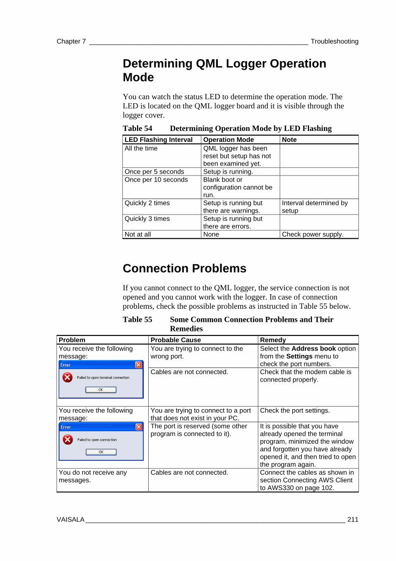
Chapter 7 ___________________________________________________________ Troubleshooting
VAISALA ______________________________________________________________________ 211
Determining QML Logger Operation Mode
You can watch the status LED to determine the operation mode. The LED is located on the QML logger board and it is visible through the logger cover.
Table 54 Determining Operation Mode by LED Flashing LED Flashing Interval Operation Mode Note All the time QML logger has been
reset but setup has not been examined yet.
Once per 5 seconds Setup is running. Once per 10 seconds Blank boot or
configuration cannot be run.
Quickly 2 times Setup is running but there are warnings.
Interval determined by setup
Quickly 3 times Setup is running but there are errors.
Not at all None Check power supply.
Connection Problems
If you cannot connect to the QML logger, the service connection is not opened and you cannot work with the logger. In case of connection problems, check the possible problems as instructed in Table 55 below.
Table 55 Some Common Connection Problems and Their Remedies
Problem Probable Cause Remedy You are trying to connect to the wrong port.
Select the Address book option from the Settings menu to check the port numbers.
You receive the following message:
Cables are not connected. Check that the modem cable is connected properly.
You are trying to connect to a port that does not exist in your PC.
Check the port settings. You receive the following message:
The port is reserved (some other program is connected to it).
It is possible that you have already opened the terminal program, minimized the window and forgotten you have already opened it, and then tried to open the program again.
You do not receive any messages.
Cables are not connected. Connect the cables as shown in section Connecting AWS Client to AWS330 on page 102.

User's Guide ______________________________________________________________________
212 _________________________________________________________________ M211296EN-A
Resetting QML Logger
To reset the QML logger, enter the reset command (recommended), or press the reset button indicated by number 1 in Figure 121 below.
1004-121
Figure 121 Reset Button on QML Logger
A short reset (pressing the reset button quickly) performs the same reset as giving the command and starts the program again. A long reset (pressing the reset button and keeping it down for a few seconds) restarts the program with a so-called blank setup. A blank setup does not run a setup file.
A blank setup may be useful if the setup is somehow defective and does not allow the opening of a terminal connection. When the blank setup is run, the QML logger communication parameters are restored to their defaults: 9600bps, 8 data, No parity, 1 stop bit.
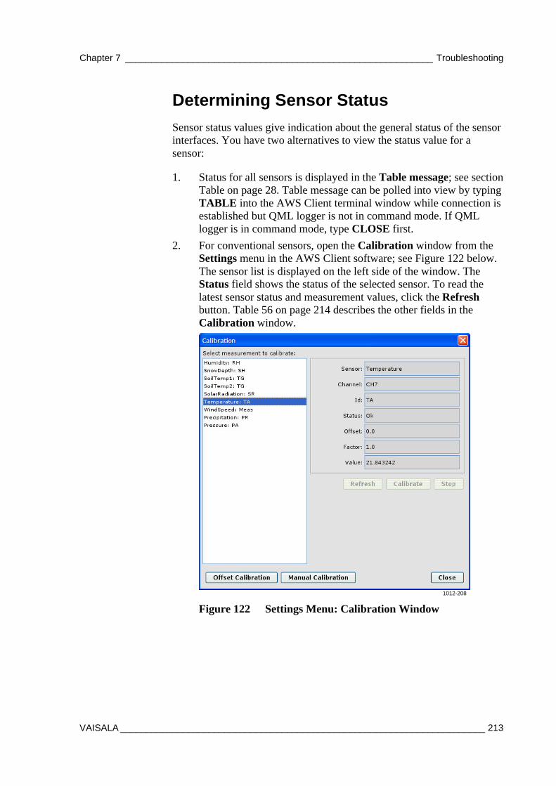
Chapter 7 ___________________________________________________________ Troubleshooting
VAISALA ______________________________________________________________________ 213
Determining Sensor Status
Sensor status values give indication about the general status of the sensor interfaces. You have two alternatives to view the status value for a sensor:
1. Status for all sensors is displayed in the Table message; see section Table on page 28. Table message can be polled into view by typing TABLE into the AWS Client terminal window while connection is established but QML logger is not in command mode. If QML logger is in command mode, type CLOSE first.
2. For conventional sensors, open the Calibration window from the Settings menu in the AWS Client software; see Figure 122 below. The sensor list is displayed on the left side of the window. The Status field shows the status of the selected sensor. To read the latest sensor status and measurement values, click the Refresh button. Table 56 on page 214 describes the other fields in the Calibration window.
1012-208
Figure 122 Settings Menu: Calibration Window
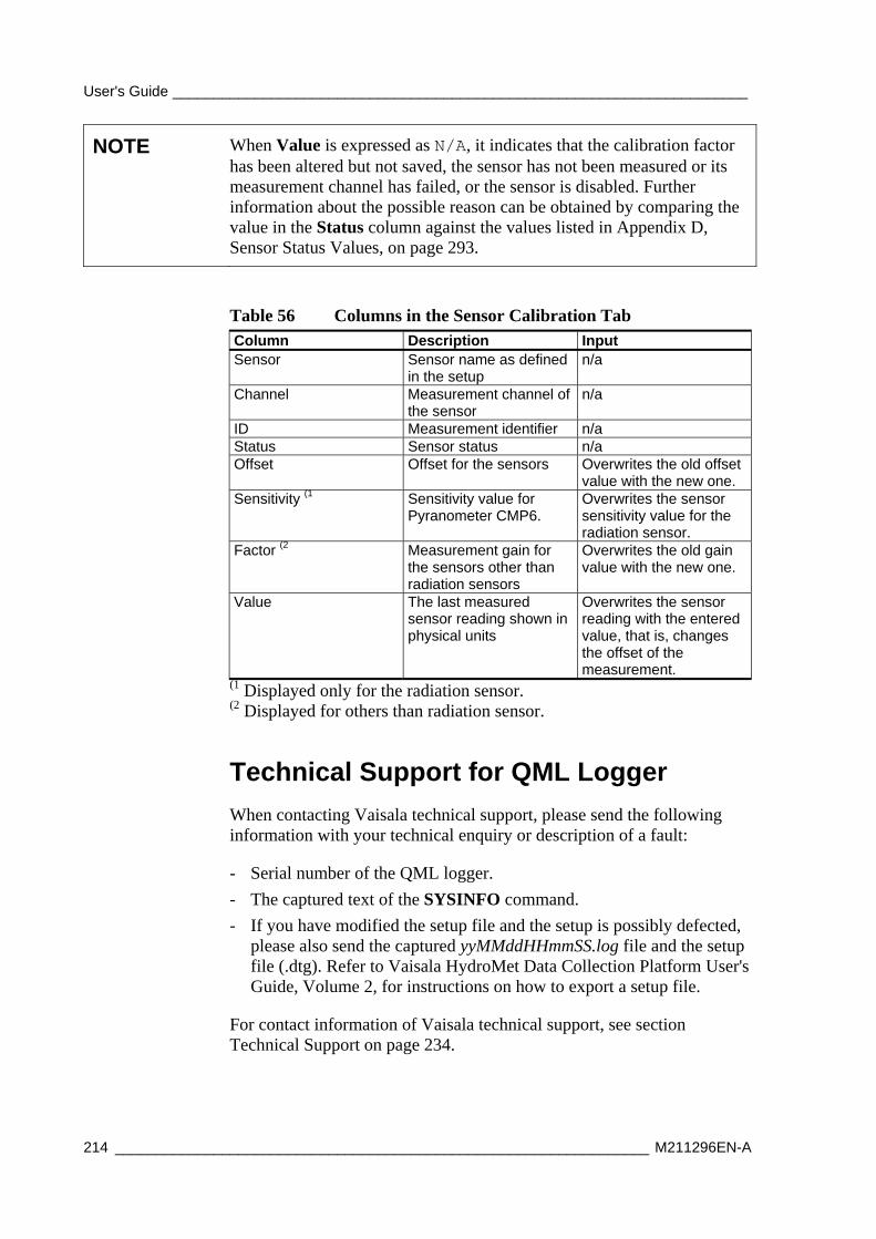
User's Guide ______________________________________________________________________
214 _________________________________________________________________ M211296EN-A
NOTE When Value is expressed as N/A, it indicates that the calibration factor has been altered but not saved, the sensor has not been measured or its measurement channel has failed, or the sensor is disabled. Further information about the possible reason can be obtained by comparing the value in the Status column against the values listed in Appendix D, Sensor Status Values, on page 293.
Table 56 Columns in the Sensor Calibration Tab Column Description Input Sensor Sensor name as defined
in the setup n/a
Channel Measurement channel of the sensor
n/a
ID Measurement identifier n/a Status Sensor status n/a Offset Offset for the sensors Overwrites the old offset
value with the new one. Sensitivity (1 Sensitivity value for
Pyranometer CMP6. Overwrites the sensor sensitivity value for the radiation sensor.
Factor (2 Measurement gain for the sensors other than radiation sensors
Overwrites the old gain value with the new one.
Value The last measured sensor reading shown in physical units
Overwrites the sensor reading with the entered value, that is, changes the offset of the measurement.
(1 Displayed only for the radiation sensor. (2 Displayed for others than radiation sensor.
Technical Support for QML Logger
When contacting Vaisala technical support, please send the following information with your technical enquiry or description of a fault:
- Serial number of the QML logger.
- The captured text of the SYSINFO command.
- If you have modified the setup file and the setup is possibly defected, please also send the captured yyMMddHHmmSS.log file and the setup file (.dtg). Refer to Vaisala HydroMet Data Collection Platform User's Guide, Volume 2, for instructions on how to export a setup file.
For contact information of Vaisala technical support, see section Technical Support on page 234.
Chapter 7 ___________________________________________________________ Troubleshooting
VAISALA ______________________________________________________________________ 215
Troubleshooting TCP/IP-Based Telemetry Typical possibilities for troubleshooting TCP/IP-based telemetry operation with the QML logger are as follows:
NOTE This manual will not attempt to give general guidelines on network design or troubleshooting issues, such as IP addressing. Troubleshooting IP networking usually also involves issues not related to the QML logger or its configuration; this section includes only the troubleshooting possibilities at the QML logger end.
1. Use the warnings command to check for any modem-related warnings.
2. Use the net warnings command to check for any IP-specific warnings.
3. Use the ipconfig command to see the current IP configuration in the QML logger. The command output gives you information on all open network interfaces and their configuration, such as IP addresses, gateways, and DNS servers.
4. Use the netif command to see whether the network interface you are trying to use is open. If required, the interface can be opened with the command netif open <interface name>.
5. Check that the IP addresses used for the QML logger interfaces are correct with respect to your overall network configuration.
6. Use the ping command to test the connection to the destination IP address or host. If the destination cannot be reached, you can test whether the connection to the gateway works; if it does, the problem might be in the connection between the gateway and the destination host.
7. For the FTP and NTP services, use the commands ftp test <server> and ntp test <server> to check the connection to the server. You can also use the ping command to check whether the server is reachable. Note that if you are accessing the destination server over the internet, the destination server needs to have a public IP address or port forwarding rules defined for NAT.
8. As applicable in your network, ensure that there are no firewalls blocking the traffic to/from the QML logger and the destination server.
User's Guide ______________________________________________________________________
216 _________________________________________________________________ M211296EN-A
9. To monitor different telemetry related services, a shell command can be used to enable extra output. Command format is
DO <Service Name> DEBUG_ON <Port>
where
<Service Name> = Name of the service to monitor; see Table 57 below
<Port> = Port where the information is sent to; see Table 58 below
For example, the following shows how this command can be used to monitor EMAIL operation remotely via TCP service connection:
/> DO EMAIL DEBUG_ON VCOM1
Debugging enabled->VCOM1
The following services can be monitored:
Table 57 List of Service Names Service name Description FTP FTP message transport VCOM0 TCP socket message transport EMAIL eMail message transport SMS SMS message transport GSM_Modem GSM modem control NTP NTP timekeeping
Depending on the used connection, the following ports are available:
Table 58 Debug Ports Connection Port Name Local service connection to COM0 COM0 Remote service connection using TCP socket VCOM1 Remote service connection using CSD dial-in DSI486_0_1
To stop monitoring a service, use the following command:
DO <Service Name> DEBUG_OFF
For example, to stop monitoring the EMAIL service:
/ > DO EMAIL DEBUG_OFF
Debugging disabled
Chapter 7 ___________________________________________________________ Troubleshooting
VAISALA ______________________________________________________________________ 217
10. To send the AT commands manually, the command interface of the modem can be directly accessed. To control the modem directly, open the service connection to the QML logger. With AWS330, the device is connected to the second DSI486 communication port at the module place MOD1, type open DSI486_0_1. To terminate this operation, type close. While the direct connection to the modem or sensor is open, any automatic operation through the connected port is blocked.
11. It is impossible to have default parameters that would work everywhere with all the different network infrastructures. If the default parameters do not seem to work, try to find out the correct parameters by establishing a manual connection between the weather station and the data collection system. Do this by, for example, using a PC terminal program. Also note that the default parameters are seldom optimal, for example, in minimizing the connection time.
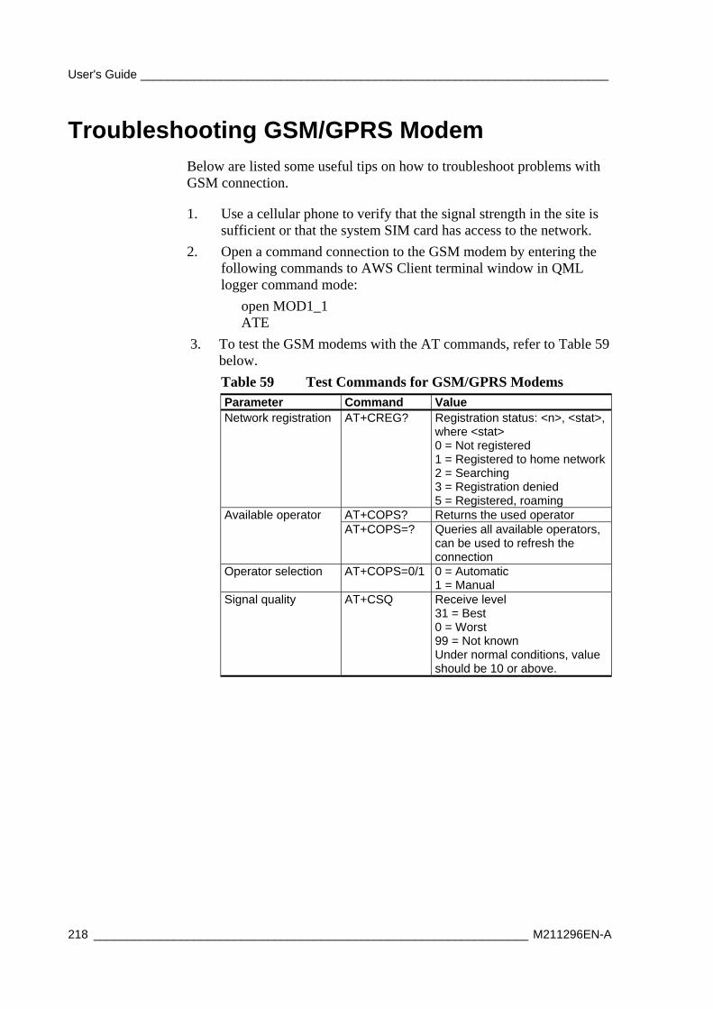
User's Guide ______________________________________________________________________
218 _________________________________________________________________ M211296EN-A
Troubleshooting GSM/GPRS Modem Below are listed some useful tips on how to troubleshoot problems with GSM connection.
1. Use a cellular phone to verify that the signal strength in the site is sufficient or that the system SIM card has access to the network.
2. Open a command connection to the GSM modem by entering the following commands to AWS Client terminal window in QML logger command mode:
open MOD1_1 ATE
3. To test the GSM modems with the AT commands, refer to Table 59 below.
Table 59 Test Commands for GSM/GPRS Modems Parameter Command Value Network registration AT+CREG? Registration status: <n>, <stat>,
where <stat> 0 = Not registered 1 = Registered to home network2 = Searching 3 = Registration denied 5 = Registered, roaming
AT+COPS? Returns the used operator Available operator AT+COPS=? Queries all available operators,
can be used to refresh the connection
Operator selection AT+COPS=0/1 0 = Automatic 1 = Manual
Signal quality AT+CSQ Receive level 31 = Best 0 = Worst 99 = Not known Under normal conditions, value should be 10 or above.
Chapter 7 ___________________________________________________________ Troubleshooting
VAISALA ______________________________________________________________________ 219
Commands for Troubleshooting Purposes For most of the sensor inputs, there are data validation parameters to check the following quality parameters for the measurement:
- Maximum value: the maximum climatological value for the sensor measurement.
- Minimum value: the minimum climatological value for the sensor measurement.
- Step change: the maximum step change for the sensor value between two consecutive measurements.
You can set all of these parameters with Lizard Setup Software. For more information, please refer to Vaisala HydroMet Data Collection Platform User's Guide, Volumes 2 and 3.
If the sensor value is outside the maximum or minimum values, or it has altered more than the maximum step change allowed, then data will be flagged as INVALID. Invalid data is typically displayed as ///// (this is a parameter that you can set). If a sensor displays invalid data, this is an indication that the sensor is faulty or out of calibration, or there is a problem in powering or measuring the sensor.
Warnings and Errors
There may be some problems if you see either of the following prompts:
/ E> / W>
/ E> means that there are errors, and / W> means that there are warnings.
It is normal to have one or two warnings after the serial connection to the QML logger has been reset; for example, if you have turned your PC off, you can ignore these warnings.
To see active warnings, type warnings. To clear active warnings, type warnings clear. Warnings indicate that there are some problems in the software.
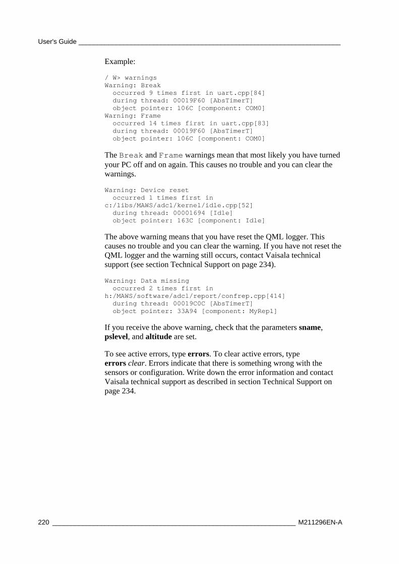
User's Guide ______________________________________________________________________
220 _________________________________________________________________ M211296EN-A
Example:
/ W> warnings Warning: Break occurred 9 times first in uart.cpp[84] during thread: 00019F60 [AbsTimerT] object pointer: 106C [component: COM0] Warning: Frame occurred 14 times first in uart.cpp[83] during thread: 00019F60 [AbsTimerT] object pointer: 106C [component: COM0]
The Break and Frame warnings mean that most likely you have turned your PC off and on again. This causes no trouble and you can clear the warnings.
Warning: Device reset occurred 1 times first in c:/libs/MAWS/adcl/kernel/idle.cpp[52] during thread: 00001694 [Idle] object pointer: 163C [component: Idle] The above warning means that you have reset the QML logger. This causes no trouble and you can clear the warning. If you have not reset the QML logger and the warning still occurs, contact Vaisala technical support (see section Technical Support on page 234).
Warning: Data missing occurred 2 times first in h:/MAWS/software/adcl/report/confrep.cpp[414] during thread: 00019C0C [AbsTimerT] object pointer: 33A94 [component: MyRep1] If you receive the above warning, check that the parameters sname, pslevel, and altitude are set.
To see active errors, type errors. To clear active errors, type errors clear. Errors indicate that there is something wrong with the sensors or configuration. Write down the error information and contact Vaisala technical support as described in section Technical Support on page 234.
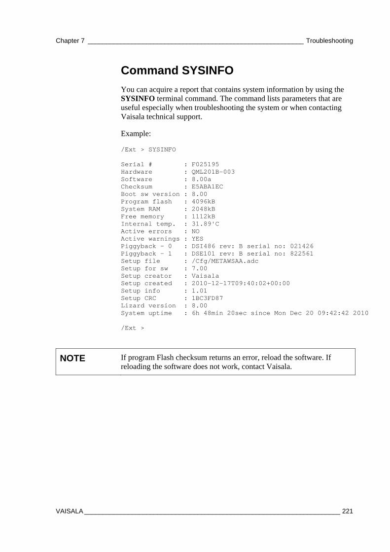
Chapter 7 ___________________________________________________________ Troubleshooting
VAISALA ______________________________________________________________________ 221
Command SYSINFO
You can acquire a report that contains system information by using the SYSINFO terminal command. The command lists parameters that are useful especially when troubleshooting the system or when contacting Vaisala technical support.
Example:
/Ext > SYSINFO Serial # : F025195 Hardware : QML201B-003 Software : 8.00a Checksum : E5ABA1EC Boot sw version : 8.00 Program flash : 4096kB System RAM : 2048kB Free memory : 1112kB Internal temp. : 31.89'C Active errors : NO Active warnings : YES Piggyback - 0 : DSI486 rev: B serial no: 021426 Piggyback - 1 : DSE101 rev: B serial no: 822561 Setup file : /Cfg/METAWSAA.adc Setup for sw : 7.00 Setup creator : Vaisala Setup created : 2010-12-17T09:40:02+00:00 Setup info : 1.01 Setup CRC : 1BC3FD87 Lizard version : 8.00 System uptime : 6h 48min 20sec since Mon Dec 20 09:42:42 2010 /Ext >
NOTE If program Flash checksum returns an error, reload the software. If reloading the software does not work, contact Vaisala.

User's Guide ______________________________________________________________________
222 _________________________________________________________________ M211296EN-A
where
Serial # = Serial number of the logger PCB Hardware = Hardware revision of the logger PCB Software = Software version for the operating software and
its checksum Boot sw version = Version of the QML logger boot software
Program flash = Total amount of program memory
System RAM = Total amount of memory on the logger Free memory = Amount of free memory on the logger Internal temp. = Internal temperature of the logger Active errors = Existence of active errors: YES/NO Active warnings = Existence of active warnings: YES/NO Piggyback - 0 = Type and serial number of the additional
module installed in the module slot 1 Piggyback - 1 = Type and serial number of the additional
module installed in the module slot 2 Setup file = File path of the running setup Setup for sw = Minimum logger firmware version required for
running the current setup Setup creator = Setup created by Setup created = Setup creation time Setup CRC = Setup checksum Lizard version = Lizard version used to create the setup System uptime = Total time that the system has been running,
calculated from the last reset
The versions of installed communication modules can be seen from SYSINFO output or in the startup message if, for example, you need to find out the version of a DSI486 module.
Example startup message from the logger:
COM0: QML201C Startup - Cold Boot Serial # : F1335009 Hardware : QML201C-003 Software : 8.00 Checksum : 815AED36 Boot sw version : 8.00 Program flash : 4096kB System RAM : 2048kB Free memory : 1626kB Internal temp. : 24.65'C Active errors : NO Active warnings : NO Piggyback - 0 : DSI486 rev: D serial no: 932365 Piggyback - 1 : DSE101 rev: B serial no: 822561 Program flash checksum (815AED36) verification...Passed
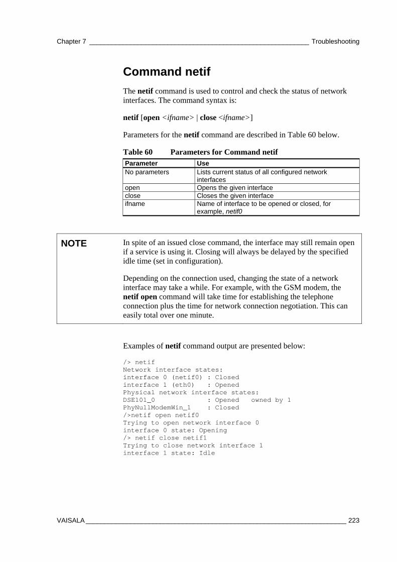
Chapter 7 ___________________________________________________________ Troubleshooting
VAISALA ______________________________________________________________________ 223
Command netif
The netif command is used to control and check the status of network interfaces. The command syntax is:
netif [open <ifname> | close <ifname>]
Parameters for the netif command are described in Table 60 below.
Table 60 Parameters for Command netif Parameter Use No parameters Lists current status of all configured network
interfaces open Opens the given interface close Closes the given interface ifname Name of interface to be opened or closed, for
example, netif0
NOTE In spite of an issued close command, the interface may still remain open if a service is using it. Closing will always be delayed by the specified idle time (set in configuration).
Depending on the connection used, changing the state of a network interface may take a while. For example, with the GSM modem, the netif open command will take time for establishing the telephone connection plus the time for network connection negotiation. This can easily total over one minute.
Examples of netif command output are presented below:
/> netif Network interface states: interface 0 (netif0) : Closed interface 1 (eth0) : Opened Physical network interface states: DSE101_0 : Opened owned by 1 PhyNullModemWin_1 : Closed />netif open netif0 Trying to open network interface 0 interface 0 state: Opening /> netif close netif1 Trying to close network interface 1 interface 1 state: Idle
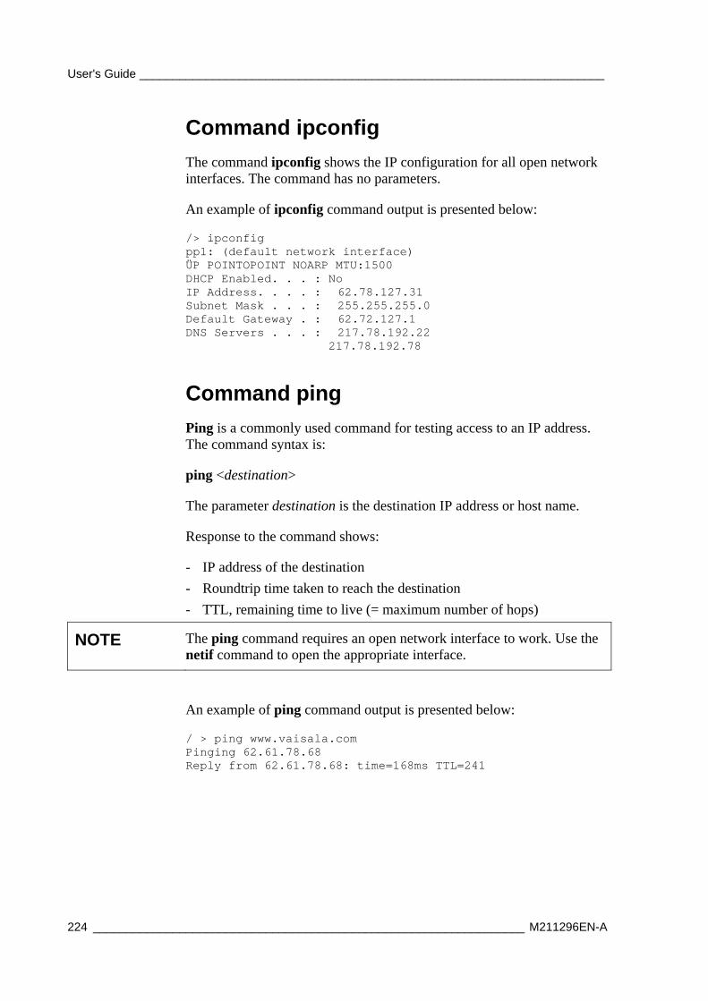
User's Guide ______________________________________________________________________
224 _________________________________________________________________ M211296EN-A
Command ipconfig
The command ipconfig shows the IP configuration for all open network interfaces. The command has no parameters.
An example of ipconfig command output is presented below:
/> ipconfig pp1: (default network interface) ÜP POINTOPOINT NOARP MTU:1500 DHCP Enabled. . . : No IP Address. . . . : 62.78.127.31 Subnet Mask . . . : 255.255.255.0 Default Gateway . : 62.72.127.1 DNS Servers . . . : 217.78.192.22 217.78.192.78
Command ping
Ping is a commonly used command for testing access to an IP address. The command syntax is:
ping <destination>
The parameter destination is the destination IP address or host name.
Response to the command shows:
- IP address of the destination
- Roundtrip time taken to reach the destination
- TTL, remaining time to live (= maximum number of hops)
NOTE The ping command requires an open network interface to work. Use the netif command to open the appropriate interface.
An example of ping command output is presented below:
/ > ping www.vaisala.com Pinging 62.61.78.68 Reply from 62.61.78.68: time=168ms TTL=241
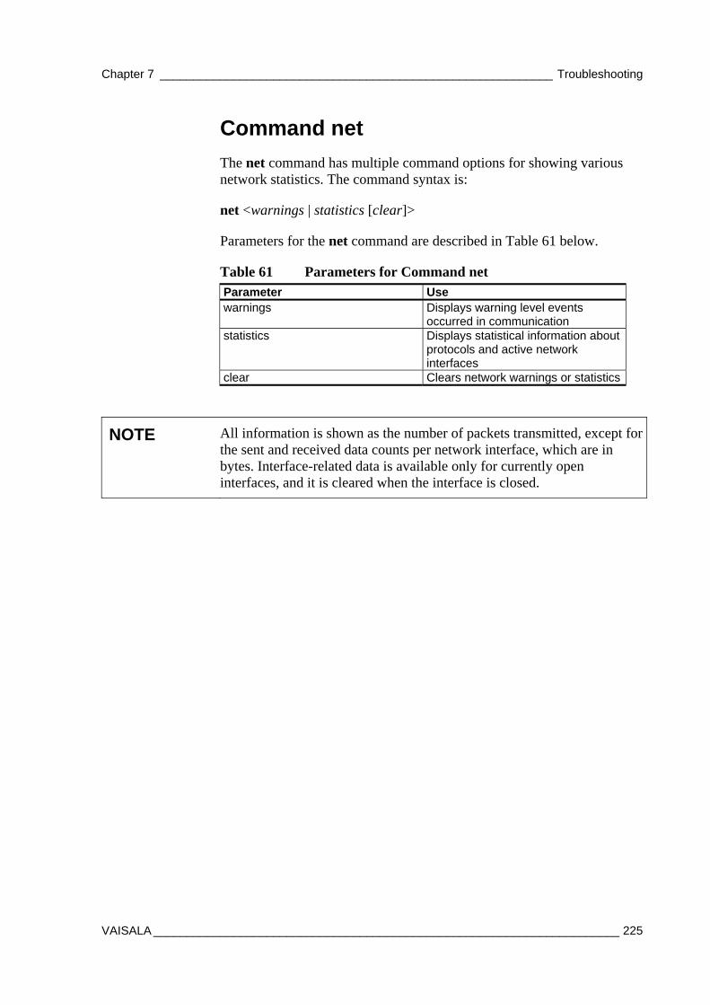
Chapter 7 ___________________________________________________________ Troubleshooting
VAISALA ______________________________________________________________________ 225
Command net
The net command has multiple command options for showing various network statistics. The command syntax is:
net <warnings | statistics [clear]>
Parameters for the net command are described in Table 61 below.
Table 61 Parameters for Command net Parameter Use warnings Displays warning level events
occurred in communication statistics Displays statistical information about
protocols and active network interfaces
clear Clears network warnings or statistics
NOTE All information is shown as the number of packets transmitted, except for the sent and received data counts per network interface, which are in bytes. Interface-related data is available only for currently open interfaces, and it is cleared when the interface is closed.
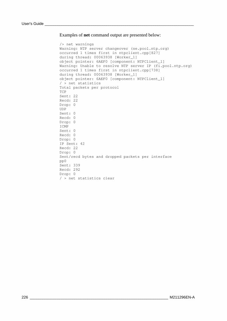
User's Guide ______________________________________________________________________
226 _________________________________________________________________ M211296EN-A
Examples of net command output are presented below:
/> net warnings Warning: NTP server changeover (se.pool.ntp.org) occurred 1 times first in ntpclient.cpp[827] during thread: 00063938 [Worker_1] object pointer: 6AEF0 [component: NTPClient_1] Warning: Unable to resolve NTP server IP (fi.pool.ntp.org) occurred 1 times first in ntpclient.cpp[738] during thread: 00063938 [Worker_1] object pointer: 6AEF0 [component: NTPClient_1] / > net statistics Total packets per protocol TCP Sent: 22 Recd: 22 Drop: 0 UDP Sent: 0 Recd: 0 Drop: 0 ICMP Sent: 0 Recd: 0 Drop: 0 IP Sent: 42 Recd: 22 Drop: 0 Sent/recd bytes and dropped packets per interface pp0 Sent: 339 Recd: 292 Drop: 0 / > net statistics clear
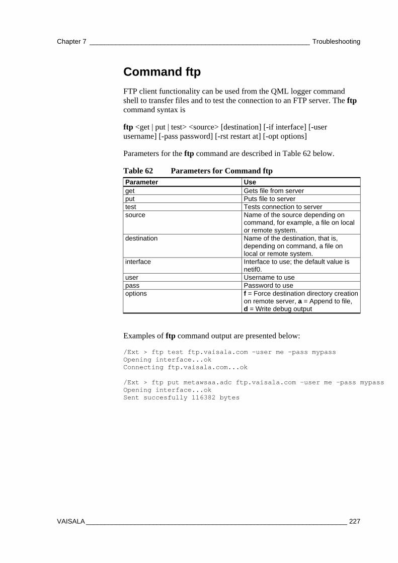
Chapter 7 ___________________________________________________________ Troubleshooting
VAISALA ______________________________________________________________________ 227
Command ftp
FTP client functionality can be used from the QML logger command shell to transfer files and to test the connection to an FTP server. The ftp command syntax is
ftp <get | put | test> <source> [destination] [-if interface] [-user username] [-pass password] [-rst restart at] [-opt options]
Parameters for the ftp command are described in Table 62 below.
Table 62 Parameters for Command ftp Parameter Use get Gets file from server put Puts file to server test Tests connection to server source Name of the source depending on
command, for example, a file on local or remote system.
destination Name of the destination, that is, depending on command, a file on local or remote system.
interface Interface to use; the default value is netif0.
user Username to use pass Password to use options f = Force destination directory creation
on remote server, a = Append to file, d = Write debug output
Examples of ftp command output are presented below:
/Ext > ftp test ftp.vaisala.com -user me -pass mypass Opening interface...ok Connecting ftp.vaisala.com...ok /Ext > ftp put metawsaa.adc ftp.vaisala.com -user me -pass mypass Opening interface...ok Sent succesfully 116382 bytes
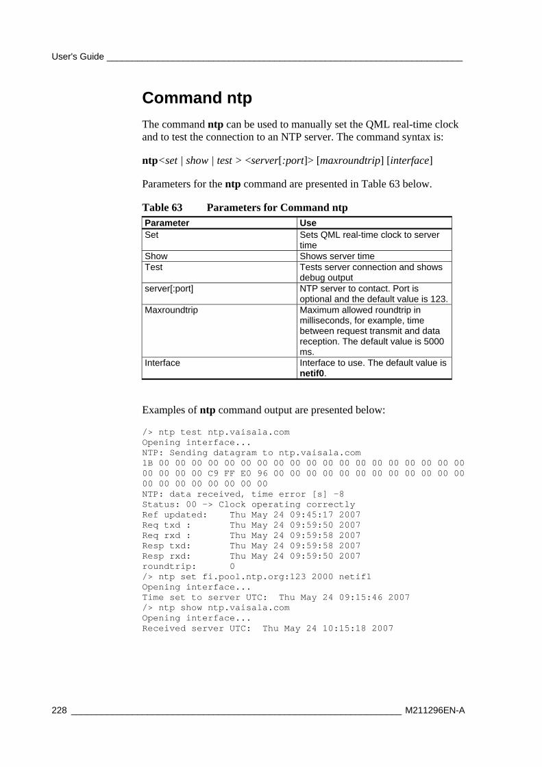
User's Guide ______________________________________________________________________
228 _________________________________________________________________ M211296EN-A
Command ntp
The command ntp can be used to manually set the QML real-time clock and to test the connection to an NTP server. The command syntax is:
ntp<set | show | test > <server[:port]> [maxroundtrip] [interface]
Parameters for the ntp command are presented in Table 63 below.
Table 63 Parameters for Command ntp Parameter Use Set Sets QML real-time clock to server
time Show Shows server time Test Tests server connection and shows
debug output server[:port] NTP server to contact. Port is
optional and the default value is 123.Maxroundtrip Maximum allowed roundtrip in
milliseconds, for example, time between request transmit and data reception. The default value is 5000 ms.
Interface Interface to use. The default value is netif0.
Examples of ntp command output are presented below:
/> ntp test ntp.vaisala.com Opening interface... NTP: Sending datagram to ntp.vaisala.com 1B 00 00 00 00 00 00 00 00 00 00 00 00 00 00 00 00 00 00 00 00 00 00 00 C9 FF E0 96 00 00 00 00 00 00 00 00 00 00 00 00 00 00 00 00 00 00 00 00 NTP: data received, time error [s] -8 Status: 00 -> Clock operating correctly Ref updated: Thu May 24 09:45:17 2007 Req txd : Thu May 24 09:59:50 2007 Req rxd : Thu May 24 09:59:58 2007 Resp txd: Thu May 24 09:59:58 2007 Resp rxd: Thu May 24 09:59:50 2007 roundtrip: 0 /> ntp set fi.pool.ntp.org:123 2000 netif1 Opening interface... Time set to server UTC: Thu May 24 09:15:46 2007 /> ntp show ntp.vaisala.com Opening interface... Received server UTC: Thu May 24 10:15:18 2007
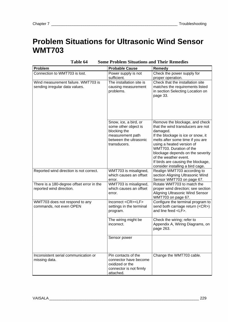
Chapter 7 ___________________________________________________________ Troubleshooting
VAISALA ______________________________________________________________________ 229
Problem Situations for Ultrasonic Wind Sensor WMT703
Table 64 Some Problem Situations and Their Remedies Problem Probable Cause Remedy Connection to WMT703 is lost. Power supply is not
sufficient. Check the power supply for proper operation.
The installation site is causing measurement problems.
Check that the installation site matches the requirements listed in section Selecting Location on page 33.
Wind measurement failure. WMT703 is sending irregular data values.
Snow, ice, a bird, or some other object is blocking the measurement path between the ultrasonic transducers.
Remove the blockage, and check that the wind transducers are not damaged. If the blockage is ice or snow, it melts after some time if you are using a heated version of WMT703. Duration of the blockage depends on the severity of the weather event. If birds are causing the blockage, consider installing a bird cage.
Reported wind direction is not correct. WMT703 is misaligned, which causes an offset error.
Realign WMT703 according to section Aligning Ultrasonic Wind Sensor WMT703 on page 67.
There is a 180-degree offset error in the reported wind direction.
WMT703 is misaligned, which causes an offset error.
Rotate WMT703 to match the proper wind direction; see section Aligning Ultrasonic Wind Sensor WMT703 on page 67.
Incorrect <CR><LF> settings in the terminal program.
Configure the terminal program to send both carriage return (<CR>) and line feed <LF>.
The wiring might be incorrect.
Check the wiring; refer to Appendix A, Wiring Diagrams, on page 263.
WMT703 does not respond to any commands, not even OPEN
Sensor power
Inconsistent serial communication or missing data.
Pin contacts of the connector have become oxidized or the connector is not firmly attached.
Change the WMT703 cable.
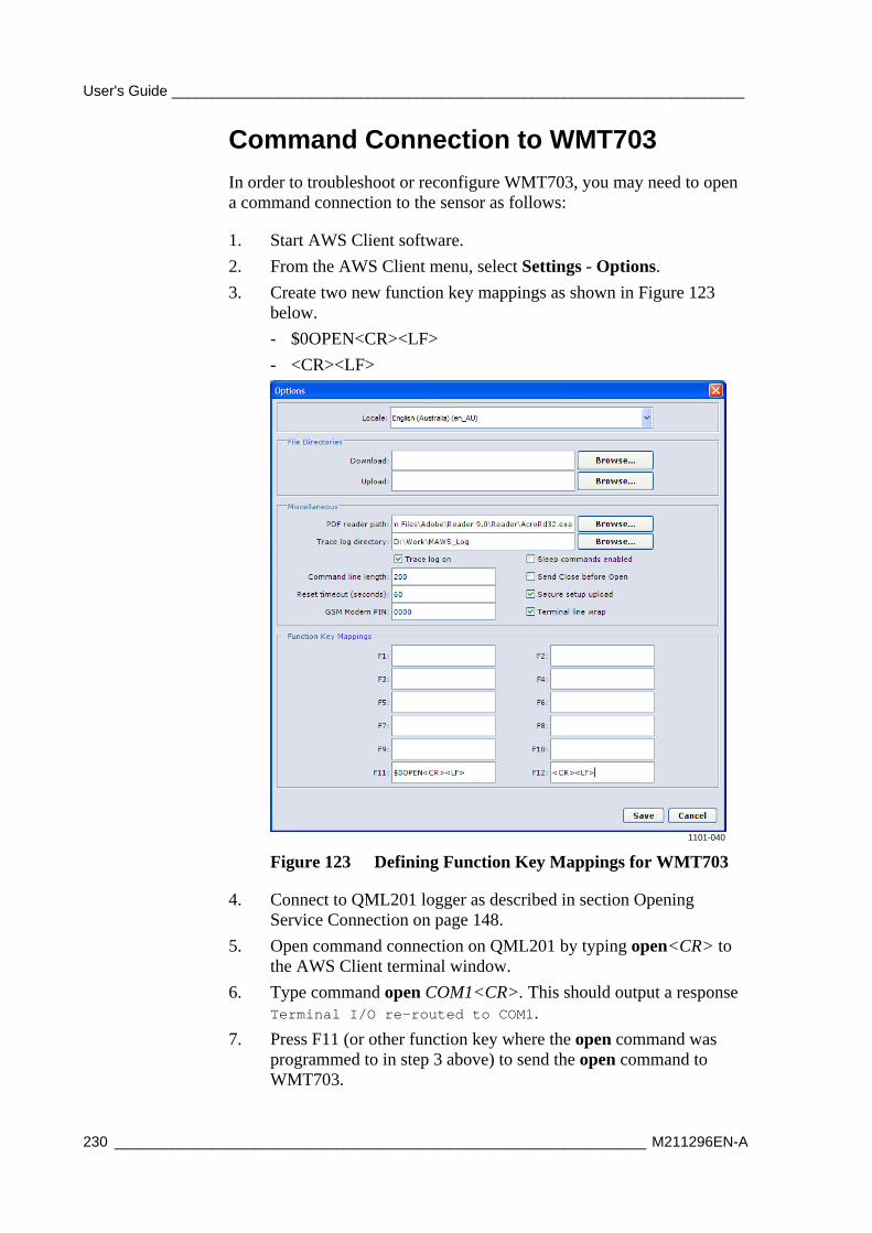
User's Guide ______________________________________________________________________
230 _________________________________________________________________ M211296EN-A
Command Connection to WMT703
In order to troubleshoot or reconfigure WMT703, you may need to open a command connection to the sensor as follows:
1. Start AWS Client software.
2. From the AWS Client menu, select Settings - Options.
3. Create two new function key mappings as shown in Figure 123 below.
- $0OPEN<CR><LF>
- <CR><LF>
1101-040
Figure 123 Defining Function Key Mappings for WMT703
4. Connect to QML201 logger as described in section Opening Service Connection on page 148.
5. Open command connection on QML201 by typing open<CR> to the AWS Client terminal window.
6. Type command open COM1<CR>. This should output a response Terminal I/O re-routed to COM1.
7. Press F11 (or other function key where the open command was programmed to in step 3 above) to send the open command to WMT703.
Chapter 7 ___________________________________________________________ Troubleshooting
VAISALA ______________________________________________________________________ 231
8. If WMT703 responds with prompt >, the connection has been successfully opened.
NOTE When entering commands for WMT703, instead of terminating command with ENTER, use the function key programmed in step 3 on page 230 to send <CR><LF> to the sensor. Also note that WMT703 does not echo characters when using RS485 link.
For additional troubleshooting instructions, see WMT700 User's Guide, manual M211095EN, included on the AWS330 installation CD.
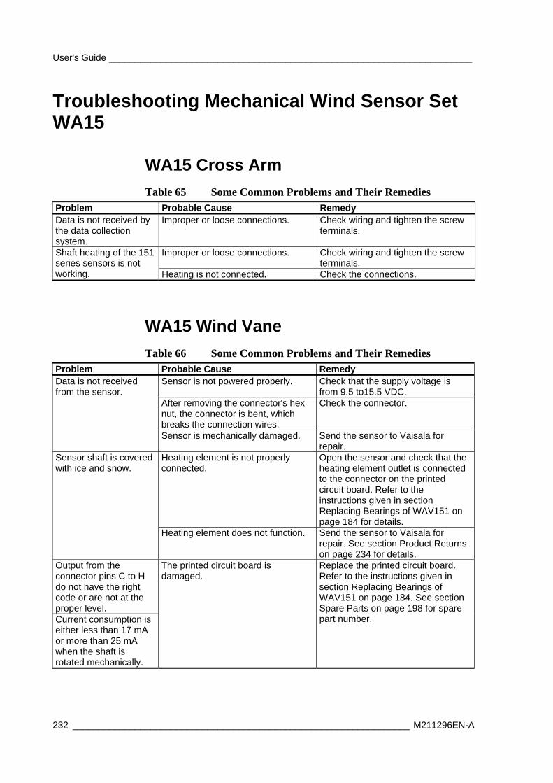
User's Guide ______________________________________________________________________
232 _________________________________________________________________ M211296EN-A
Troubleshooting Mechanical Wind Sensor Set WA15
WA15 Cross Arm
Table 65 Some Common Problems and Their Remedies Problem Probable Cause Remedy Data is not received by the data collection system.
Improper or loose connections. Check wiring and tighten the screw terminals.
Improper or loose connections. Check wiring and tighten the screw terminals.
Shaft heating of the 151 series sensors is not working. Heating is not connected. Check the connections.
WA15 Wind Vane
Table 66 Some Common Problems and Their Remedies Problem Probable Cause Remedy
Sensor is not powered properly. Check that the supply voltage is from 9.5 to15.5 VDC.
After removing the connector's hex nut, the connector is bent, which breaks the connection wires.
Check the connector.
Data is not received from the sensor.
Sensor is mechanically damaged. Send the sensor to Vaisala for repair.
Heating element is not properly connected.
Open the sensor and check that the heating element outlet is connected to the connector on the printed circuit board. Refer to the instructions given in section Replacing Bearings of WAV151 on page 184 for details.
Sensor shaft is covered with ice and snow.
Heating element does not function. Send the sensor to Vaisala for repair. See section Product Returns on page 234 for details.
Output from the connector pins C to H do not have the right code or are not at the proper level. Current consumption is either less than 17 mA or more than 25 mA when the shaft is rotated mechanically.
The printed circuit board is damaged.
Replace the printed circuit board. Refer to the instructions given in section Replacing Bearings of WAV151 on page 184. See section Spare Parts on page 198 for spare part number.
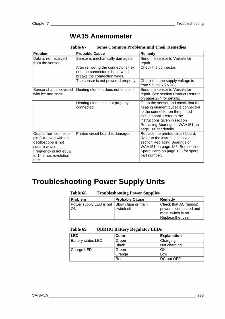
Chapter 7 ___________________________________________________________ Troubleshooting
VAISALA ______________________________________________________________________ 233
WA15 Anemometer
Table 67 Some Common Problems and Their Remedies Problem Probable Cause Remedy
Sensor is mechanically damaged. Send the sensor to Vaisala for repair.
After removing the connector's hex nut, the connector is bent, which breaks the connection wires.
Check the connector.
Data is not received from the sensor.
The sensor is not powered properly. Check that the supply voltage is from 9.5 to15.5 VDC.
Sensor shaft is covered with ice and snow.
Heating element does not function. Send the sensor to Vaisala for repair. See section Product Returns on page 234 for details.
Heating element is not properly connected.
Open the sensor and check that the heating element outlet is connected to the connector on the printed circuit board. Refer to the instructions given in section Replacing Bearings of WAA151 on page 188 for details.
Output from connector pin C tracked with an oscilloscope is not square wave. Frequency is not equal to 14 times revolution rate.
Printed circuit board is damaged. Replace the printed circuit board. Refer to the instructions given in section Replacing Bearings of WAA151 on page 188. See section Spare Parts on page 198 for spare part number.
Troubleshooting Power Supply Units Table 68 Troubleshooting Power Supplies Problem Probably Cause Remedy Power supply LED is not ON.
Blown fuse or main switch off
Check that AC (mains) power is connected and main switch is on. Replace the fuse.
Table 69 QBR101 Battery Regulator LEDs LED Color Explanation
Green Charging Battery status LED Blank Not charging Green OK Orange Low
Charge LED
Red DC out OFF
User's Guide ______________________________________________________________________
234 _________________________________________________________________ M211296EN-A
Technical Support For technical questions, contact the Vaisala technical support by e-mail at [email protected]. Provide at least the following supporting information:
- Name and model of the product in question
- Serial number of the product
- Name and location of the installation site
- Name and contact information of a technically competent person who can provide further information on the problem.
Before returning a product, please request an RMA from Vaisala technical support; see section Requesting RMA on page 235.
Vaisala Service Centers Vaisala Service Centers perform calibrations and adjustments as well as repair and spare part services. For contact information in your region, visit www.vaisala.com/services/servicecenters.html.
Vaisala Service Centers also offer accredited calibrations, maintenance contracts, and a calibration reminder program. Do not hesitate to contact them to get further information.
Product Returns If the product must be returned for service, see www.vaisala.com/services/return.html.
For contact information of Vaisala Service Centers, see www.vaisala.com/services/servicecenters.html.
Chapter 7 ___________________________________________________________ Troubleshooting
VAISALA ______________________________________________________________________ 235
Requesting RMA If the product needs repair, please follow the instructions below to speed up the process and to avoid extra costs to you.
1. Read the warranty information.
2. Contact Vaisala technical support via e-mail or fax and request for RMA (Return Material Authorization) and shipping instructions.
3. Proceed as instructed by Vaisala technical support; refer to section Technical Support on page 234.
NOTE RMA must always be requested from Vaisala technical support before returning any faulty material.

User's Guide ______________________________________________________________________
236 _________________________________________________________________ M211296EN-A
This page intentionally left blank.
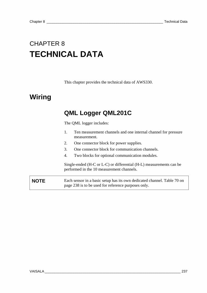
Chapter 8 ____________________________________________________________ Technical Data
VAISALA ______________________________________________________________________ 237
CHAPTER 8
TECHNICAL DATA
This chapter provides the technical data of AWS330.
Wiring
QML Logger QML201C
The QML logger includes:
1. Ten measurement channels and one internal channel for pressure measurement.
2. One connector block for power supplies.
3. One connector block for communication channels.
4. Two blocks for optional communication modules.
Single-ended (H-C or L-C) or differential (H-L) measurements can be performed in the 10 measurement channels.
NOTE Each sensor in a basic setup has its own dedicated channel. Table 70 on page 238 is to be used for reference purposes only.
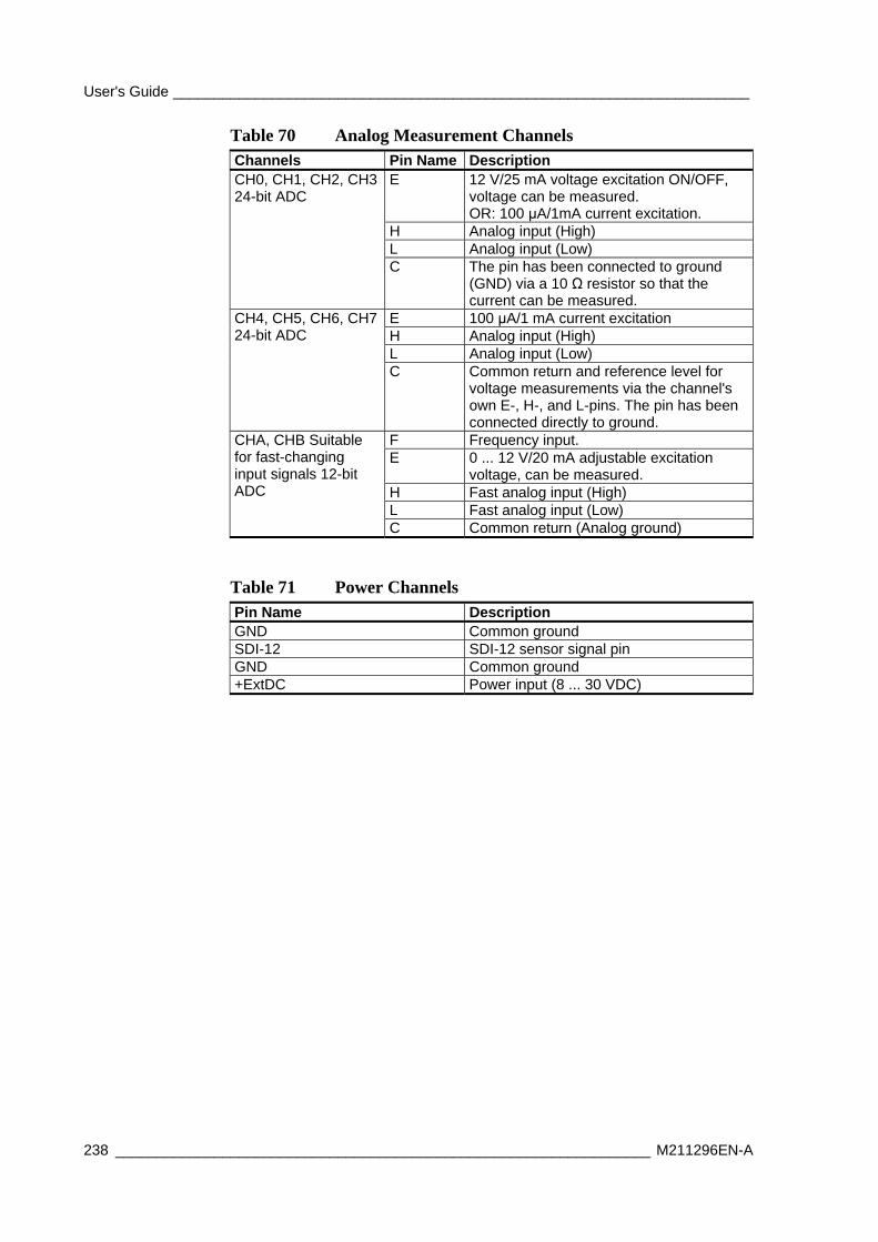
User's Guide ______________________________________________________________________
238 _________________________________________________________________ M211296EN-A
Table 70 Analog Measurement Channels Channels Pin Name Description
E 12 V/25 mA voltage excitation ON/OFF, voltage can be measured. OR: 100 μA/1mA current excitation.
H Analog input (High) L Analog input (Low)
CH0, CH1, CH2, CH3 24-bit ADC
C The pin has been connected to ground (GND) via a 10 Ω resistor so that the current can be measured.
E 100 μA/1 mA current excitation H Analog input (High) L Analog input (Low)
CH4, CH5, CH6, CH7 24-bit ADC
C Common return and reference level for voltage measurements via the channel's own E-, H-, and L-pins. The pin has been connected directly to ground.
F Frequency input. E 0 ... 12 V/20 mA adjustable excitation
voltage, can be measured. H Fast analog input (High) L Fast analog input (Low)
CHA, CHB Suitable for fast-changing input signals 12-bit ADC
C Common return (Analog ground)
Table 71 Power Channels Pin Name Description GND Common ground SDI-12 SDI-12 sensor signal pin GND Common ground +ExtDC Power input (8 ... 30 VDC)
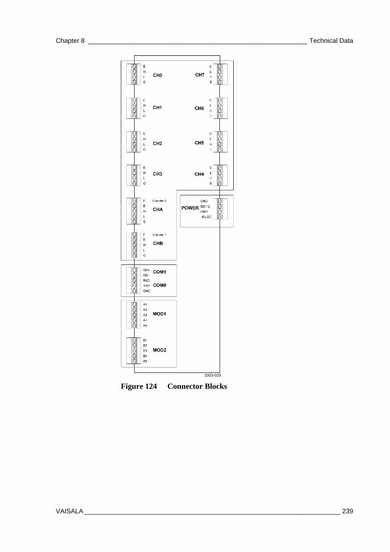
Chapter 8 ____________________________________________________________ Technical Data
VAISALA ______________________________________________________________________ 239
1003-029
Figure 124 Connector Blocks
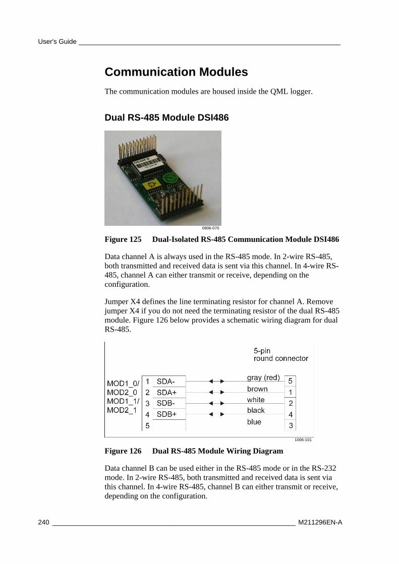
User's Guide ______________________________________________________________________
240 _________________________________________________________________ M211296EN-A
Communication Modules
The communication modules are housed inside the QML logger.
Dual RS-485 Module DSI486
0906-070
Figure 125 Dual-Isolated RS-485 Communication Module DSI486
Data channel A is always used in the RS-485 mode. In 2-wire RS-485, both transmitted and received data is sent via this channel. In 4-wire RS-485, channel A can either transmit or receive, depending on the configuration.
Jumper X4 defines the line terminating resistor for channel A. Remove jumper X4 if you do not need the terminating resistor of the dual RS-485 module. Figure 126 below provides a schematic wiring diagram for dual RS-485.
1006-101
Figure 126 Dual RS-485 Module Wiring Diagram
Data channel B can be used either in the RS-485 mode or in the RS-232 mode. In 2-wire RS-485, both transmitted and received data is sent via this channel. In 4-wire RS-485, channel B can either transmit or receive, depending on the configuration.
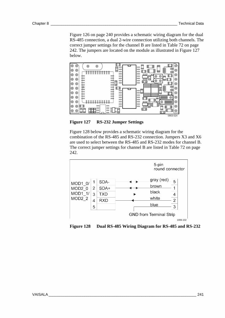
Chapter 8 ____________________________________________________________ Technical Data
VAISALA ______________________________________________________________________ 241
Figure 126 on page 240 provides a schematic wiring diagram for the dual RS-485 connection, a dual 2-wire connection utilizing both channels. The correct jumper settings for the channel B are listed in Table 72 on page 242. The jumpers are located on the module as illustrated in Figure 127 below.
0903-024
Figure 127 RS-232 Jumper Settings
Figure 128 below provides a schematic wiring diagram for the combination of the RS-485 and RS-232 connection. Jumpers X3 and X6 are used to select between the RS-485 and RS-232 modes for channel B. The correct jumper settings for channel B are listed in Table 72 on page 242.
1006-102
Figure 128 Dual RS-485 Wiring Diagram for RS-485 and RS-232
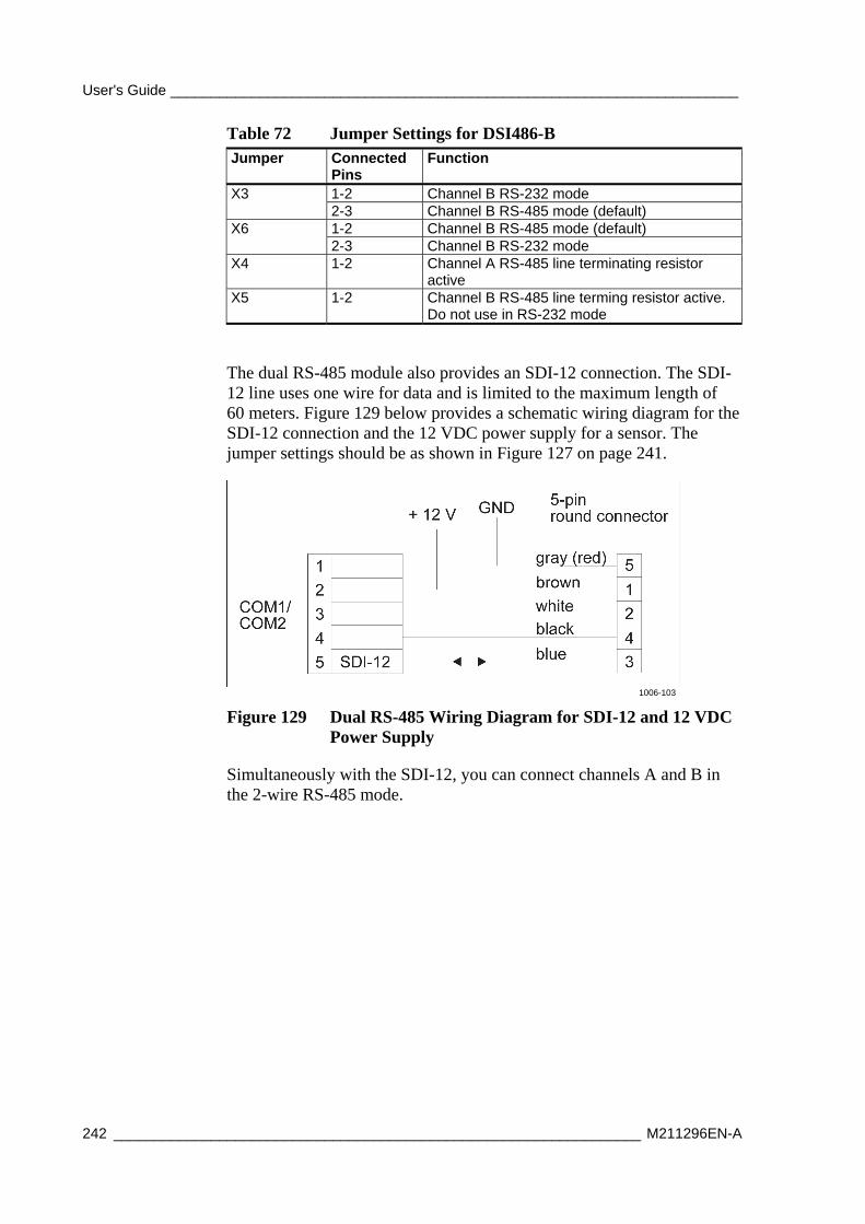
User's Guide ______________________________________________________________________
242 _________________________________________________________________ M211296EN-A
Table 72 Jumper Settings for DSI486-B Jumper Connected
Pins Function
1-2 Channel B RS-232 mode X3 2-3 Channel B RS-485 mode (default) 1-2 Channel B RS-485 mode (default) X6 2-3 Channel B RS-232 mode
X4 1-2 Channel A RS-485 line terminating resistor active
X5 1-2 Channel B RS-485 line terming resistor active. Do not use in RS-232 mode
The dual RS-485 module also provides an SDI-12 connection. The SDI-12 line uses one wire for data and is limited to the maximum length of 60 meters. Figure 129 below provides a schematic wiring diagram for the SDI-12 connection and the 12 VDC power supply for a sensor. The jumper settings should be as shown in Figure 127 on page 241.
1006-103
Figure 129 Dual RS-485 Wiring Diagram for SDI-12 and 12 VDC Power Supply
Simultaneously with the SDI-12, you can connect channels A and B in the 2-wire RS-485 mode.
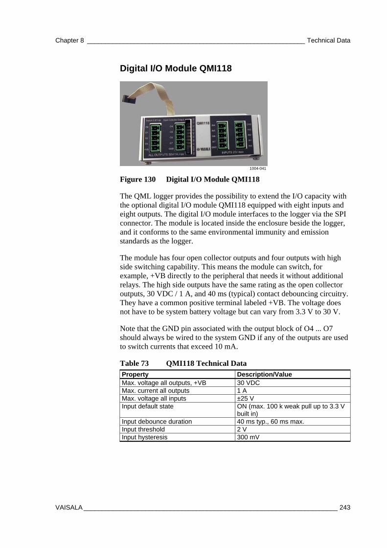
Chapter 8 ____________________________________________________________ Technical Data
VAISALA ______________________________________________________________________ 243
Digital I/O Module QMI118
1004-041
Figure 130 Digital I/O Module QMI118
The QML logger provides the possibility to extend the I/O capacity with the optional digital I/O module QMI118 equipped with eight inputs and eight outputs. The digital I/O module interfaces to the logger via the SPI connector. The module is located inside the enclosure beside the logger, and it conforms to the same environmental immunity and emission standards as the logger.
The module has four open collector outputs and four outputs with high side switching capability. This means the module can switch, for example, +VB directly to the peripheral that needs it without additional relays. The high side outputs have the same rating as the open collector outputs, 30 VDC / 1 A, and 40 ms (typical) contact debouncing circuitry. They have a common positive terminal labeled +VB. The voltage does not have to be system battery voltage but can vary from 3.3 V to 30 V.
Note that the GND pin associated with the output block of O4 ... O7 should always be wired to the system GND if any of the outputs are used to switch currents that exceed 10 mA.
Table 73 QMI118 Technical Data Property Description/Value Max. voltage all outputs, +VB 30 VDC Max. current all outputs 1 A Max. voltage all inputs ±25 V Input default state ON (max. 100 k weak pull up to 3.3 V
built in) Input debounce duration 40 ms typ., 60 ms max. Input threshold 2 V Input hysteresis 300 mV
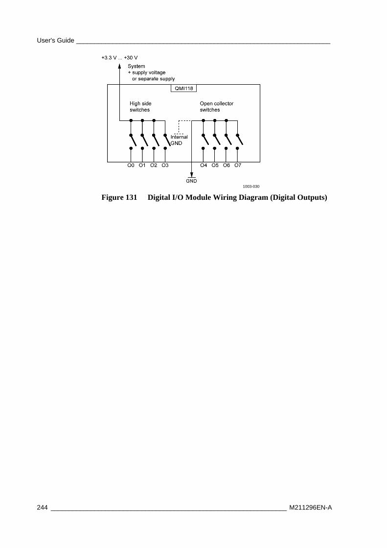
User's Guide ______________________________________________________________________
244 _________________________________________________________________ M211296EN-A
1003-030
Figure 131 Digital I/O Module Wiring Diagram (Digital Outputs)

Chapter 8 ____________________________________________________________ Technical Data
VAISALA ______________________________________________________________________ 245
Ethernet Communication Module DSE101
1004-122
Figure 132 Ethernet Communication Module DSE101
The Ethernet module DSE101 provides a 10base-T connection, which is compatible with 100 Mbps and 1 G switches; DSE101, however, operates at 10 Mbps. Supported by software, the module allows virtual serial port connections and socket connections to be established to the QML logger.
1003-031
Figure 133 DSE101 Ethernet Module Wiring Diagram
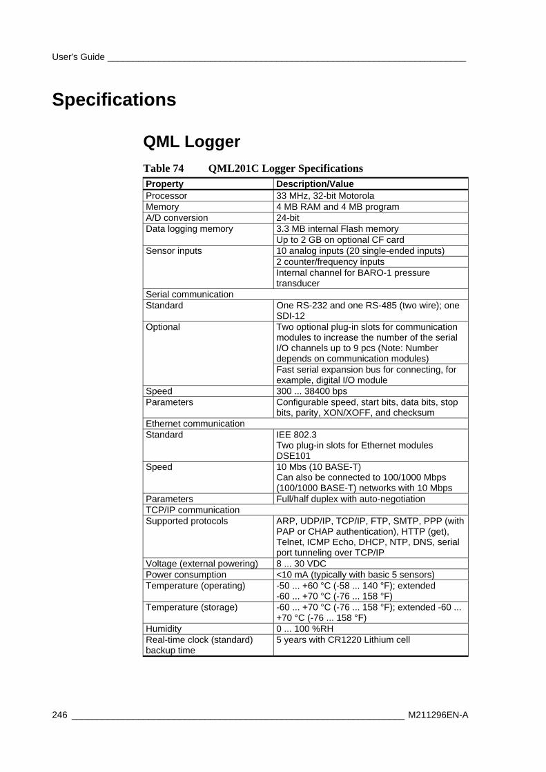
User's Guide ______________________________________________________________________
246 _________________________________________________________________ M211296EN-A
Specifications
QML Logger
Table 74 QML201C Logger Specifications Property Description/Value Processor 33 MHz, 32-bit Motorola Memory 4 MB RAM and 4 MB program A/D conversion 24-bit
3.3 MB internal Flash memory Data logging memory Up to 2 GB on optional CF card 10 analog inputs (20 single-ended inputs) 2 counter/frequency inputs
Sensor inputs
Internal channel for BARO-1 pressure transducer
Serial communication Standard One RS-232 and one RS-485 (two wire); one
SDI-12 Two optional plug-in slots for communication modules to increase the number of the serial I/O channels up to 9 pcs (Note: Number depends on communication modules)
Optional
Fast serial expansion bus for connecting, for example, digital I/O module
Speed 300 ... 38400 bps Parameters Configurable speed, start bits, data bits, stop
bits, parity, XON/XOFF, and checksum Ethernet communication Standard IEE 802.3
Two plug-in slots for Ethernet modules DSE101
Speed 10 Mbs (10 BASE-T) Can also be connected to 100/1000 Mbps (100/1000 BASE-T) networks with 10 Mbps
Parameters Full/half duplex with auto-negotiation TCP/IP communication Supported protocols ARP, UDP/IP, TCP/IP, FTP, SMTP, PPP (with
PAP or CHAP authentication), HTTP (get), Telnet, ICMP Echo, DHCP, NTP, DNS, serial port tunneling over TCP/IP
Voltage (external powering) 8 ... 30 VDC Power consumption <10 mA (typically with basic 5 sensors) Temperature (operating) -50 ... +60 °C (-58 ... 140 °F); extended
-60 ... +70 °C (-76 ... 158 °F) Temperature (storage) -60 ... +70 °C (-76 ... 158 °F); extended -60 ...
+70 °C (-76 ... 158 °F) Humidity 0 ... 100 %RH Real-time clock (standard) backup time
5 years with CR1220 Lithium cell
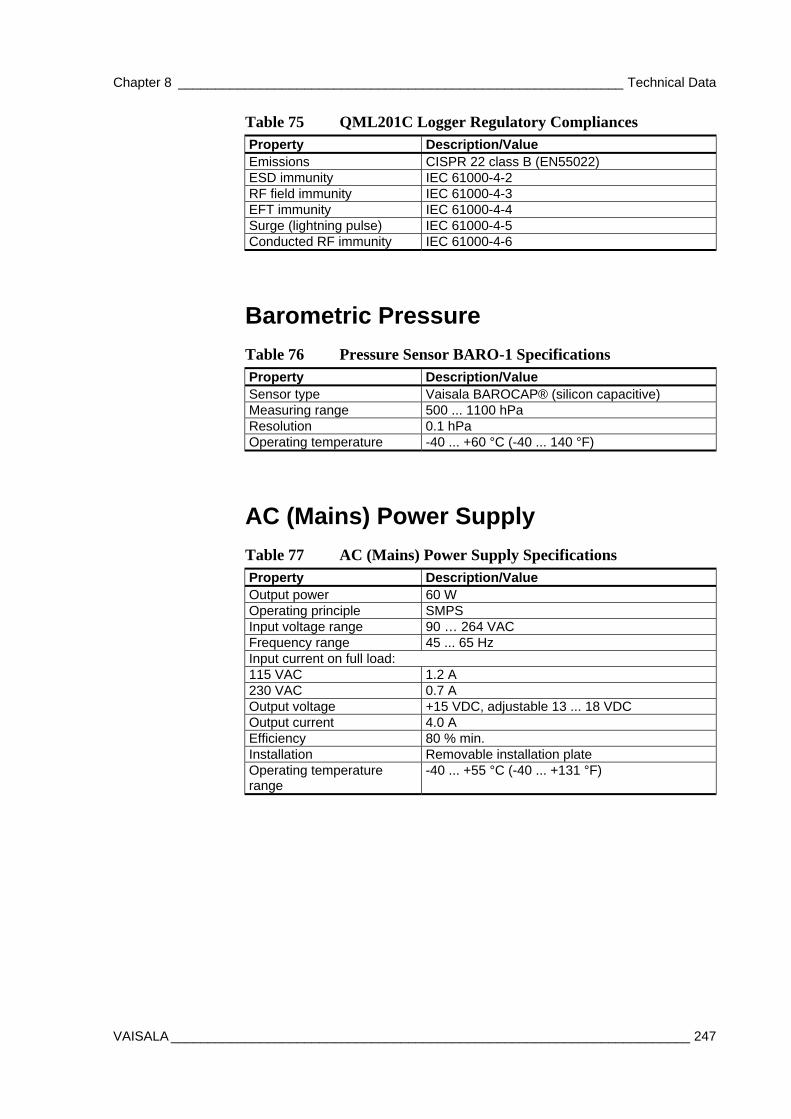
Chapter 8 ____________________________________________________________ Technical Data
VAISALA ______________________________________________________________________ 247
Table 75 QML201C Logger Regulatory Compliances Property Description/Value Emissions CISPR 22 class B (EN55022) ESD immunity IEC 61000-4-2 RF field immunity IEC 61000-4-3 EFT immunity IEC 61000-4-4 Surge (lightning pulse) IEC 61000-4-5 Conducted RF immunity IEC 61000-4-6
Barometric Pressure
Table 76 Pressure Sensor BARO-1 Specifications Property Description/Value Sensor type Vaisala BAROCAP® (silicon capacitive) Measuring range 500 ... 1100 hPa Resolution 0.1 hPa Operating temperature -40 ... +60 °C (-40 ... 140 °F)
AC (Mains) Power Supply
Table 77 AC (Mains) Power Supply Specifications Property Description/Value Output power 60 W Operating principle SMPS Input voltage range 90 … 264 VAC Frequency range 45 ... 65 Hz Input current on full load: 115 VAC 1.2 A 230 VAC 0.7 A Output voltage +15 VDC, adjustable 13 ... 18 VDC Output current 4.0 A Efficiency 80 % min. Installation Removable installation plate Operating temperature range
-40 ... +55 °C (-40 ... +131 °F)
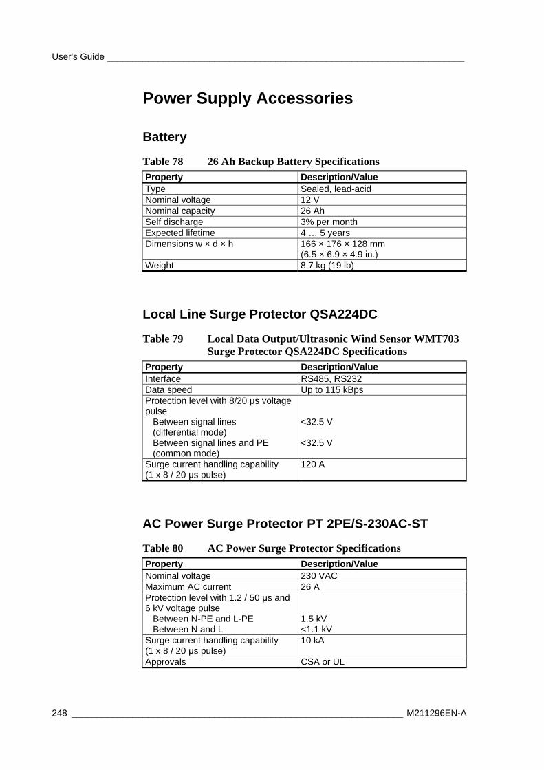
User's Guide ______________________________________________________________________
248 _________________________________________________________________ M211296EN-A
Power Supply Accessories
Battery
Table 78 26 Ah Backup Battery Specifications Property Description/Value Type Sealed, lead-acid Nominal voltage 12 V Nominal capacity 26 Ah Self discharge 3% per month Expected lifetime 4 … 5 years Dimensions w × d × h 166 × 176 × 128 mm
(6.5 × 6.9 × 4.9 in.) Weight 8.7 kg (19 lb)
Local Line Surge Protector QSA224DC
Table 79 Local Data Output/Ultrasonic Wind Sensor WMT703 Surge Protector QSA224DC Specifications
Property Description/Value Interface RS485, RS232 Data speed Up to 115 kBps Protection level with 8/20 μs voltage pulse Between signal lines (differential mode) Between signal lines and PE (common mode)
<32.5 V <32.5 V
Surge current handling capability (1 x 8 / 20 μs pulse)
120 A
AC Power Surge Protector PT 2PE/S-230AC-ST
Table 80 AC Power Surge Protector Specifications Property Description/Value Nominal voltage 230 VAC Maximum AC current 26 A Protection level with 1.2 / 50 μs and 6 kV voltage pulse Between N-PE and L-PE Between N and L
1.5 kV <1.1 kV
Surge current handling capability (1 x 8 / 20 μs pulse)
10 kA
Approvals CSA or UL
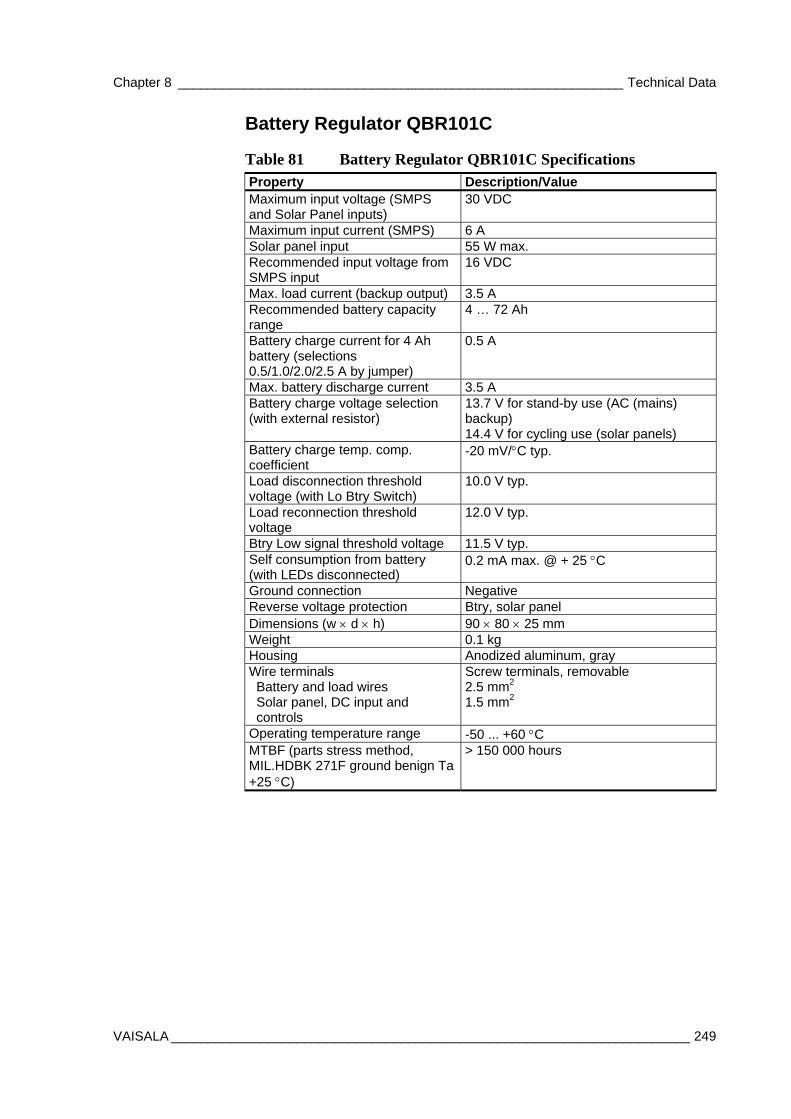
Chapter 8 ____________________________________________________________ Technical Data
VAISALA ______________________________________________________________________ 249
Battery Regulator QBR101C
Table 81 Battery Regulator QBR101C Specifications Property Description/Value Maximum input voltage (SMPS and Solar Panel inputs)
30 VDC
Maximum input current (SMPS) 6 A Solar panel input 55 W max. Recommended input voltage from SMPS input
16 VDC
Max. load current (backup output) 3.5 A Recommended battery capacity range
4 … 72 Ah
Battery charge current for 4 Ah battery (selections 0.5/1.0/2.0/2.5 A by jumper)
0.5 A
Max. battery discharge current 3.5 A Battery charge voltage selection (with external resistor)
13.7 V for stand-by use (AC (mains) backup) 14.4 V for cycling use (solar panels)
Battery charge temp. comp. coefficient
-20 mV/C typ.
Load disconnection threshold voltage (with Lo Btry Switch)
10.0 V typ.
Load reconnection threshold voltage
12.0 V typ.
Btry Low signal threshold voltage 11.5 V typ. Self consumption from battery (with LEDs disconnected)
0.2 mA max. @ + 25 C
Ground connection Negative Reverse voltage protection Btry, solar panel Dimensions (w d h) 90 80 25 mm Weight 0.1 kg Housing Anodized aluminum, gray Wire terminals Battery and load wires Solar panel, DC input and controls
Screw terminals, removable 2.5 mm2 1.5 mm2
Operating temperature range -50 ... +60 C MTBF (parts stress method, MIL.HDBK 271F ground benign Ta +25 C)
> 150 000 hours
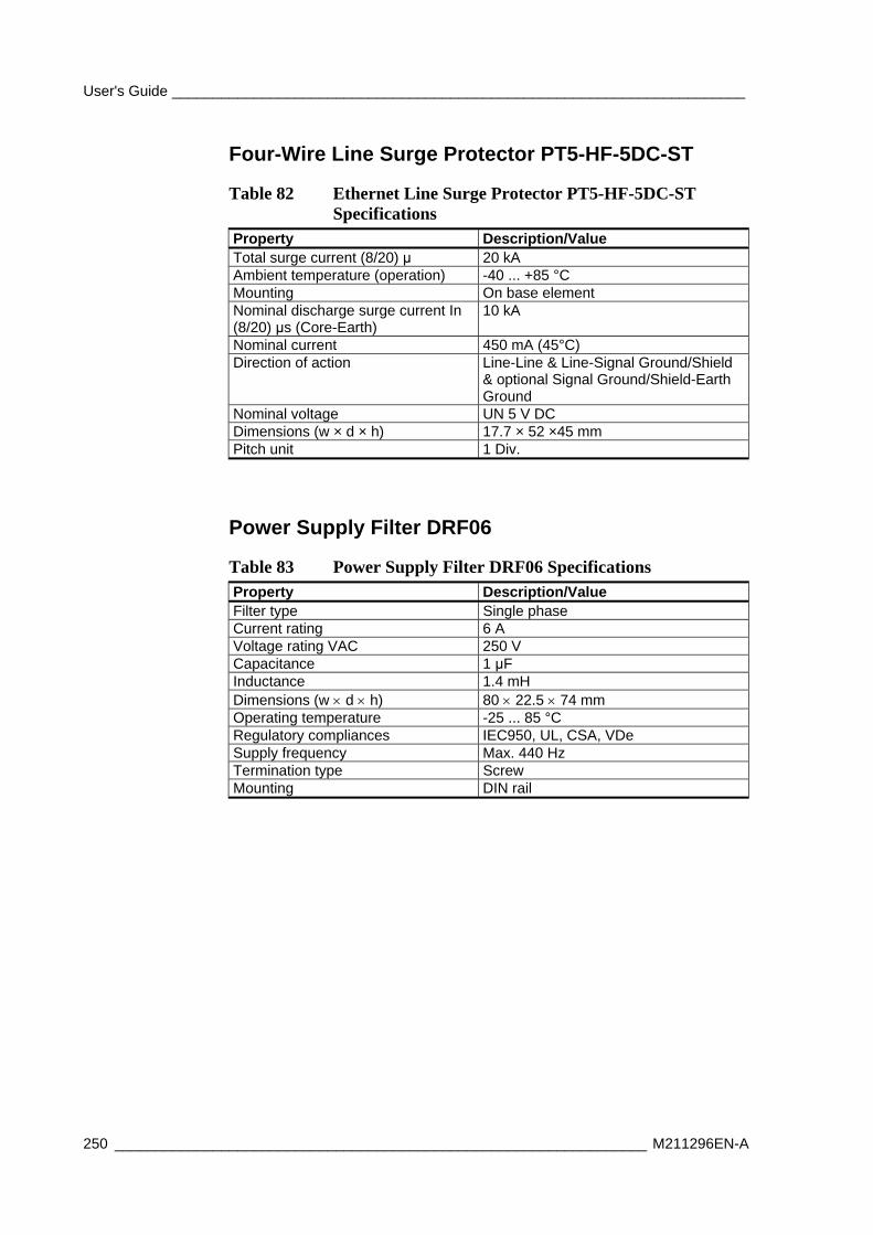
User's Guide ______________________________________________________________________
250 _________________________________________________________________ M211296EN-A
Four-Wire Line Surge Protector PT5-HF-5DC-ST
Table 82 Ethernet Line Surge Protector PT5-HF-5DC-ST Specifications
Property Description/Value Total surge current (8/20) μ 20 kA Ambient temperature (operation) -40 ... +85 °C Mounting On base element Nominal discharge surge current In (8/20) μs (Core-Earth)
10 kA
Nominal current 450 mA (45°C) Direction of action Line-Line & Line-Signal Ground/Shield
& optional Signal Ground/Shield-Earth Ground
Nominal voltage UN 5 V DC Dimensions (w × d × h) 17.7 × 52 ×45 mm Pitch unit 1 Div.
Power Supply Filter DRF06
Table 83 Power Supply Filter DRF06 Specifications Property Description/Value Filter type Single phase Current rating 6 A Voltage rating VAC 250 V Capacitance 1 μF Inductance 1.4 mH Dimensions (w d h) 80 22.5 74 mm Operating temperature -25 ... 85 °C Regulatory compliances IEC950, UL, CSA, VDe Supply frequency Max. 440 Hz Termination type Screw Mounting DIN rail
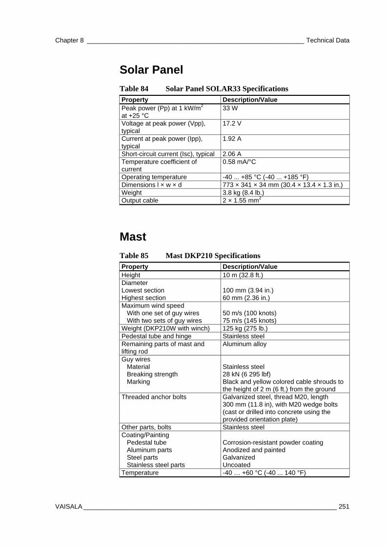
Chapter 8 ____________________________________________________________ Technical Data
VAISALA ______________________________________________________________________ 251
Solar Panel
Table 84 Solar Panel SOLAR33 Specifications Property Description/Value Peak power (Pp) at 1 kW/m2 at +25 °C
33 W
Voltage at peak power (Vpp), typical
17.2 V
Current at peak power (Ipp), typical
1.92 A
Short-circuit current (Isc), typical 2.06 A Temperature coefficient of current
0.58 mA/°C
Operating temperature -40 ... +85 °C (-40 ... +185 °F) Dimensions l × w × d 773 × 341 × 34 mm (30.4 × 13.4 × 1.3 in.) Weight 3.8 kg (8.4 lb.) Output cable 2 × 1.55 mm2
Mast
Table 85 Mast DKP210 Specifications Property Description/Value Height 10 m (32.8 ft.) Diameter Lowest section Highest section
100 mm (3.94 in.) 60 mm (2.36 in.)
Maximum wind speed With one set of guy wires With two sets of guy wires
50 m/s (100 knots) 75 m/s (145 knots)
Weight (DKP210W with winch) 125 kg (275 lb.) Pedestal tube and hinge Stainless steel Remaining parts of mast and lifting rod
Aluminum alloy
Guy wires Material Breaking strength Marking
Stainless steel 28 kN (6 295 lbf) Black and yellow colored cable shrouds to the height of 2 m (6 ft.) from the ground
Threaded anchor bolts Galvanized steel, thread M20, length 300 mm (11.8 in), with M20 wedge bolts (cast or drilled into concrete using the provided orientation plate)
Other parts, bolts Stainless steel Coating/Painting Pedestal tube Aluminum parts Steel parts Stainless steel parts
Corrosion-resistant powder coating Anodized and painted Galvanized Uncoated
Temperature -40 … +60 °C (-40 ... 140 °F)
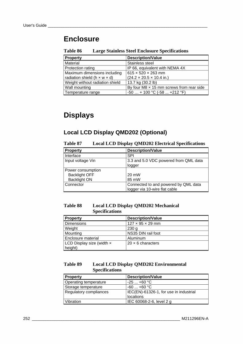
User's Guide ______________________________________________________________________
252 _________________________________________________________________ M211296EN-A
Enclosure
Table 86 Large Stainless Steel Enclosure Specifications Property Description/Value Material Stainless steel Protection rating IP 66, equivalent with NEMA 4X Maximum dimensions including radiation shield (h × w × d)
615 × 520 × 263 mm (24.2 × 20.5 × 10.4 in.)
Weight without radiation shield 13.7 kg (30.2 lb) Wall mounting By four M8 × 15 mm screws from rear side Temperature range -50 … + 100 °C (-58 ... +212 °F)
Displays
Local LCD Display QMD202 (Optional)
Table 87 Local LCD Display QMD202 Electrical Specifications Property Description/Value Interface SPI Input voltage Vin 3.3 and 5.0 VDC powered from QML data
logger Power consumption Backlight OFF Backlight ON
20 mW 85 mW
Connector Connected to and powered by QML data logger via 10-wire flat cable
Table 88 Local LCD Display QMD202 Mechanical Specifications
Property Description/Value Dimensions 127 × 95 × 29 mm Weight 230 g Mounting NS35 DIN rail foot Enclosure material Aluminum LCD Display size (width × height)
20 × 6 characters
Table 89 Local LCD Display QMD202 Environmental Specifications
Property Description/Value Operating temperature -25 ... +60 °C Storage temperature -60 ... +60 °C Regulatory compliances IEC(EN)-61326-1, for use in industrial
locations Vibration IEC 60068-2-6, level 2 g
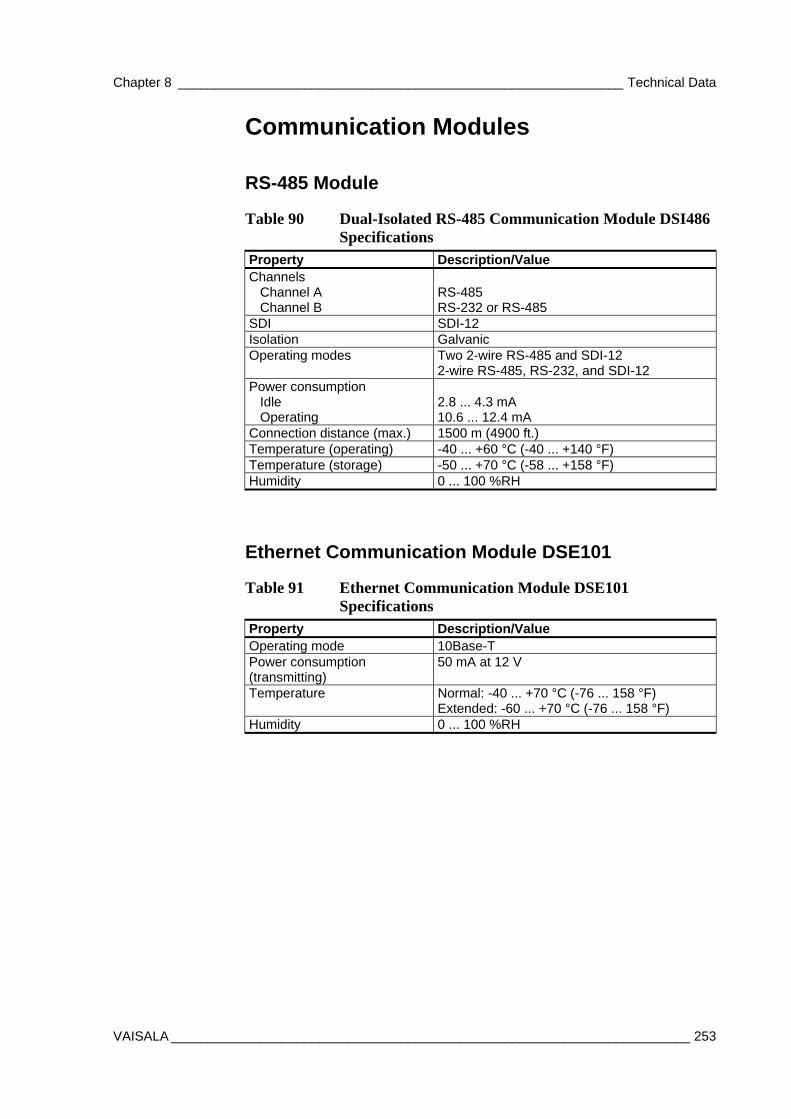
Chapter 8 ____________________________________________________________ Technical Data
VAISALA ______________________________________________________________________ 253
Communication Modules
RS-485 Module
Table 90 Dual-Isolated RS-485 Communication Module DSI486 Specifications
Property Description/Value Channels Channel A Channel B
RS-485 RS-232 or RS-485
SDI SDI-12 Isolation Galvanic Operating modes Two 2-wire RS-485 and SDI-12
2-wire RS-485, RS-232, and SDI-12 Power consumption Idle Operating
2.8 ... 4.3 mA 10.6 ... 12.4 mA
Connection distance (max.) 1500 m (4900 ft.) Temperature (operating) -40 ... +60 °C (-40 ... +140 °F) Temperature (storage) -50 ... +70 °C (-58 ... +158 °F) Humidity 0 ... 100 %RH
Ethernet Communication Module DSE101
Table 91 Ethernet Communication Module DSE101 Specifications
Property Description/Value Operating mode 10Base-T Power consumption (transmitting)
50 mA at 12 V
Temperature Normal: -40 ... +70 °C (-76 ... 158 °F) Extended: -60 ... +70 °C (-76 ... 158 °F)
Humidity 0 ... 100 %RH
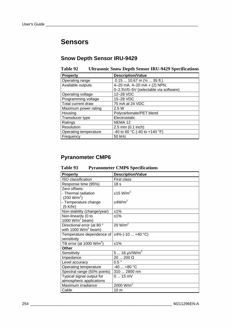
User's Guide ______________________________________________________________________
254 _________________________________________________________________ M211296EN-A
Sensors
Snow Depth Sensor IRU-9429
Table 92 Ultrasonic Snow Depth Sensor IRU-9429 Specifications Property Description/Value Operating range 0.15 ... 10.67 m (½ ... 35 ft.) Available outputs 4–20 mA, 4–20 mA + (2) NPN,
0–2.5V/0–5V (selectable via software) Operating voltage 12–28 VDC Programming voltage 15–28 VDC Total current draw 75 mA at 24 VDC Maximum power rating 2.5 W Housing Polycarbonate/PET blend Transducer type Electrostatic Ratings NEMA 12 Resolution 2.5 mm (0.1 inch) Operating temperature -40 to 60 °C (-40 to +140 °F) Frequency 50 kHz
Pyranometer CMP6
Table 93 Pyranometer CMP6 Specifications Property Description/Value ISO classification First class Response time (95%) 18 s Zero offsets: - Thermal radiation (200 W/m2) - Temperature change (5 K/hr)
±15 W/m2 ±4W/m2
Non-stability (change/year) ±1% Non-linearity (0 to 1000 W/m2 beam)
±1%
Directional error (at 80 ° with 1000 W/m2 beam)
20 W/m2
Temperature dependence of sensitivity
±4% (-10 ... +40 °C)
Tilt error (at 1000 W/m2) ±1% Other Sensitivity 5 ... 16 μV/W/m2 Impedance 20 ... 200 Ω Level accuracy 0.5 ° Operating temperature -40 ... +80 °C Spectral range (50% points) 310 ... 2800 nm Typical signal output for atmospheric applications
0 ... 15 mV
Maximum irradiance 2000 W/m2 Cable 10 m
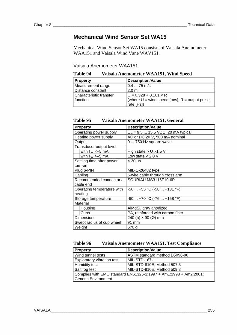
Chapter 8 ____________________________________________________________ Technical Data
VAISALA ______________________________________________________________________ 255
Mechanical Wind Sensor Set WA15
Mechanical Wind Sensor Set WA15 consists of Vaisala Anemometer WAA151 and Vaisala Wind Vane WAV151.
Vaisala Anemometer WAA151
Table 94 Vaisala Anemometer WAA151, Wind Speed Property Description/Value Measurement range 0.4 ... 75 m/s Distance constant 2.0 m Characteristic transfer function
U = 0.328 + 0.101 × R (where U = wind speed [m/s], R = output pulse rate [Hz])
Table 95 Vaisala Anemometer WAA151, General Property Description/Value Operating power supply Uin = 9.5 ... 15.5 VDC, 20 mA typical Heating power supply AC or DC 20 V, 500 mA nominal Output 0 ... 750 Hz square wave Transducer output level with Iout <+5 mA High state > Uin-1.5 V with Iout >–5 mA Low state < 2.0 V Settling time after power turn-on
< 30 µs
Plug 6-PIN MIL-C-26482 type Cabling 6-wire cable through cross arm Recommended connector at cable end
SOURIAU MS3116F10-6P
Operating temperature with heating
-50 ... +55 °C (-58 ... +131 °F)
Storage temperature -60 ... +70 °C (-76 ... +158 °F) Material Housing AlMgSi, gray anodized Cups PA, reinforced with carbon fiber Dimensions 240 (h) × 90 (Ø) mm Swept radius of cup wheel 91 mm Weight 570 g
Table 96 Vaisala Anemometer WAA151, Test Compliance Property Description/Value Wind tunnel tests ASTM standard method D5096-90 Exploratory vibration test MIL-STD-167-1 Humidity test MIL-STD-810E, Method 507.3 Salt fog test MIL-STD-810E, Method 509.3 Complies with EMC standard EN61326-1:1997 + Am1:1998 + Am2:2001; Generic Environment
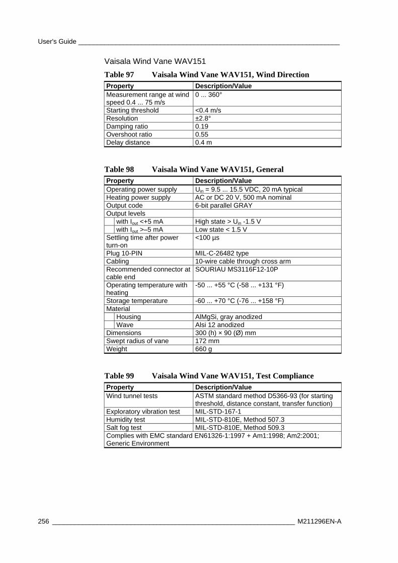
User's Guide ______________________________________________________________________
256 _________________________________________________________________ M211296EN-A
Vaisala Wind Vane WAV151
Table 97 Vaisala Wind Vane WAV151, Wind Direction Property Description/Value Measurement range at wind speed 0.4 ... 75 m/s
0 ... 360°
Starting threshold <0.4 m/s Resolution ±2.8° Damping ratio 0.19 Overshoot ratio 0.55 Delay distance 0.4 m
Table 98 Vaisala Wind Vane WAV151, General Property Description/Value Operating power supply Uin = 9.5 ... 15.5 VDC, 20 mA typical Heating power supply AC or DC 20 V, 500 mA nominal Output code 6-bit parallel GRAY Output levels with Iout <+5 mA High state > Uin -1.5 V with Iout >–5 mA Low state < 1.5 V Settling time after power turn-on
<100 µs
Plug 10-PIN MIL-C-26482 type Cabling 10-wire cable through cross arm Recommended connector at cable end
SOURIAU MS3116F12-10P
Operating temperature with heating
-50 ... +55 °C (-58 ... +131 °F)
Storage temperature -60 ... +70 °C (-76 ... +158 °F) Material Housing AlMgSi, gray anodized Wave Alsi 12 anodized Dimensions 300 (h) × 90 (Ø) mm Swept radius of vane 172 mm Weight 660 g
Table 99 Vaisala Wind Vane WAV151, Test Compliance Property Description/Value Wind tunnel tests ASTM standard method D5366-93 (for starting
threshold, distance constant, transfer function) Exploratory vibration test MIL-STD-167-1 Humidity test MIL-STD-810E, Method 507.3 Salt fog test MIL-STD-810E, Method 509.3 Complies with EMC standard EN61326-1:1997 + Am1:1998; Am2:2001; Generic Environment
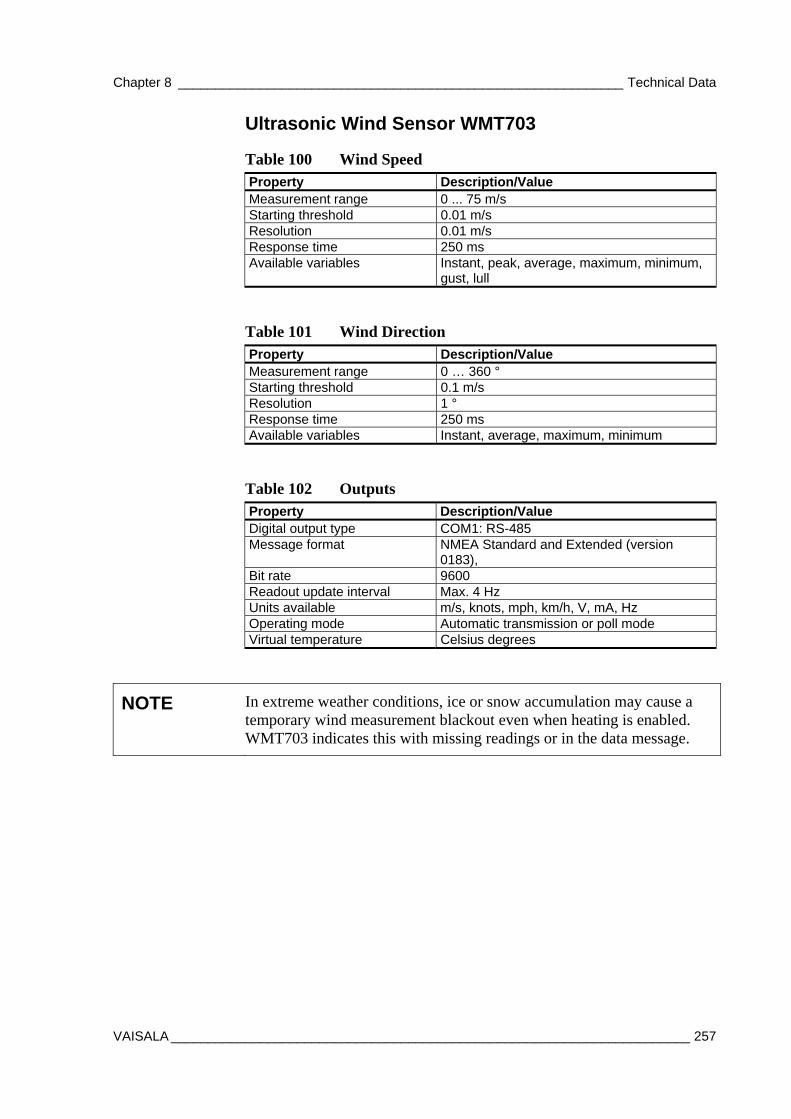
Chapter 8 ____________________________________________________________ Technical Data
VAISALA ______________________________________________________________________ 257
Ultrasonic Wind Sensor WMT703
Table 100 Wind Speed Property Description/Value Measurement range 0 ... 75 m/s Starting threshold 0.01 m/s Resolution 0.01 m/s Response time 250 ms Available variables Instant, peak, average, maximum, minimum,
gust, lull
Table 101 Wind Direction Property Description/Value Measurement range 0 … 360 ° Starting threshold 0.1 m/s Resolution 1 ° Response time 250 ms Available variables Instant, average, maximum, minimum
Table 102 Outputs Property Description/Value Digital output type COM1: RS-485 Message format NMEA Standard and Extended (version
0183), Bit rate 9600 Readout update interval Max. 4 Hz Units available m/s, knots, mph, km/h, V, mA, Hz Operating mode Automatic transmission or poll mode Virtual temperature Celsius degrees
NOTE In extreme weather conditions, ice or snow accumulation may cause a temporary wind measurement blackout even when heating is enabled. WMT703 indicates this with missing readings or in the data message.
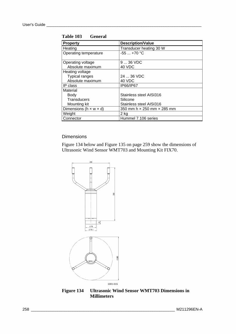
User's Guide ______________________________________________________________________
258 _________________________________________________________________ M211296EN-A
Table 103 General Property Description/Value Heating Transducer heating 30 W Operating temperature
-55 ... +70 °C
Operating voltage Absolute maximum
9 ... 36 VDC 40 VDC
Heating voltage Typical ranges Absolute maximum
24 ... 36 VDC 40 VDC
IP class IP66/IP67 Material Body Transducers Mounting kit
Stainless steel AISI316 Silicone Stainless steel AISI316
Dimensions (h × w × d) 350 mm h × 250 mm × 285 mm Weight 2 kg Connector Hummel 7.106 series
Dimensions
Figure 134 below and Figure 135 on page 259 show the dimensions of Ultrasonic Wind Sensor WMT703 and Mounting Kit FIX70.
1001-015
Figure 134 Ultrasonic Wind Sensor WMT703 Dimensions in Millimeters
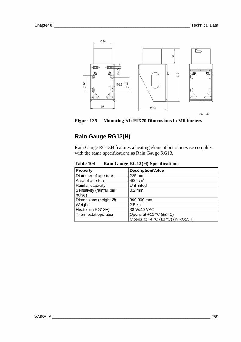
Chapter 8 ____________________________________________________________ Technical Data
VAISALA ______________________________________________________________________ 259
1004-117
Figure 135 Mounting Kit FIX70 Dimensions in Millimeters
Rain Gauge RG13(H)
Rain Gauge RG13H features a heating element but otherwise complies with the same specifications as Rain Gauge RG13.
Table 104 Rain Gauge RG13(H) Specifications Property Description/Value Diameter of aperture 225 mm Area of aperture 400 cm2 Rainfall capacity Unlimited Sensitivity (rainfall per pulse)
0.2 mm
Dimensions (height Ø) 390 300 mm Weight 2.5 kg Heater (in RG13H) 38 W/40 VAC Thermostat operation Opens at +11 °C (±3 °C)
Closes at +4 °C (±3 °C) (in RG13H)
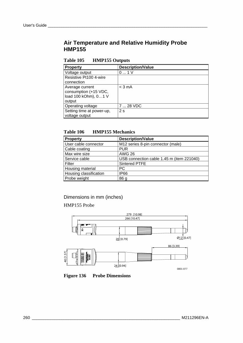
User's Guide ______________________________________________________________________
260 _________________________________________________________________ M211296EN-A
Air Temperature and Relative Humidity Probe HMP155
Table 105 HMP155 Outputs Property Description/Value Voltage output 0 ... 1 V Resistive Pt100 4-wire connection
Average current consumption (+15 VDC, load 100 kOhm), 0…1 V output
< 3 mA
Operating voltage 7 ... 28 VDC Setting time at power-up, voltage output
2 s
Table 106 HMP155 Mechanics Property Description/Value User cable connector M12 series 8-pin connector (male) Cable coating PUR Max wire size AWG 26 Service cable USB connection cable 1.45 m (item 221040) Filter Sintered PTFE Housing material PC Housing classification IP66 Probe weight 86 g
Dimensions in mm (inches)
HMP155 Probe
Ø12 [0.47]20 [0.79]
24 [0.94]
86 [3.39]
279266 [10.47]
40 [1
.57]
[10.98]
0801-077
Figure 136 Probe Dimensions
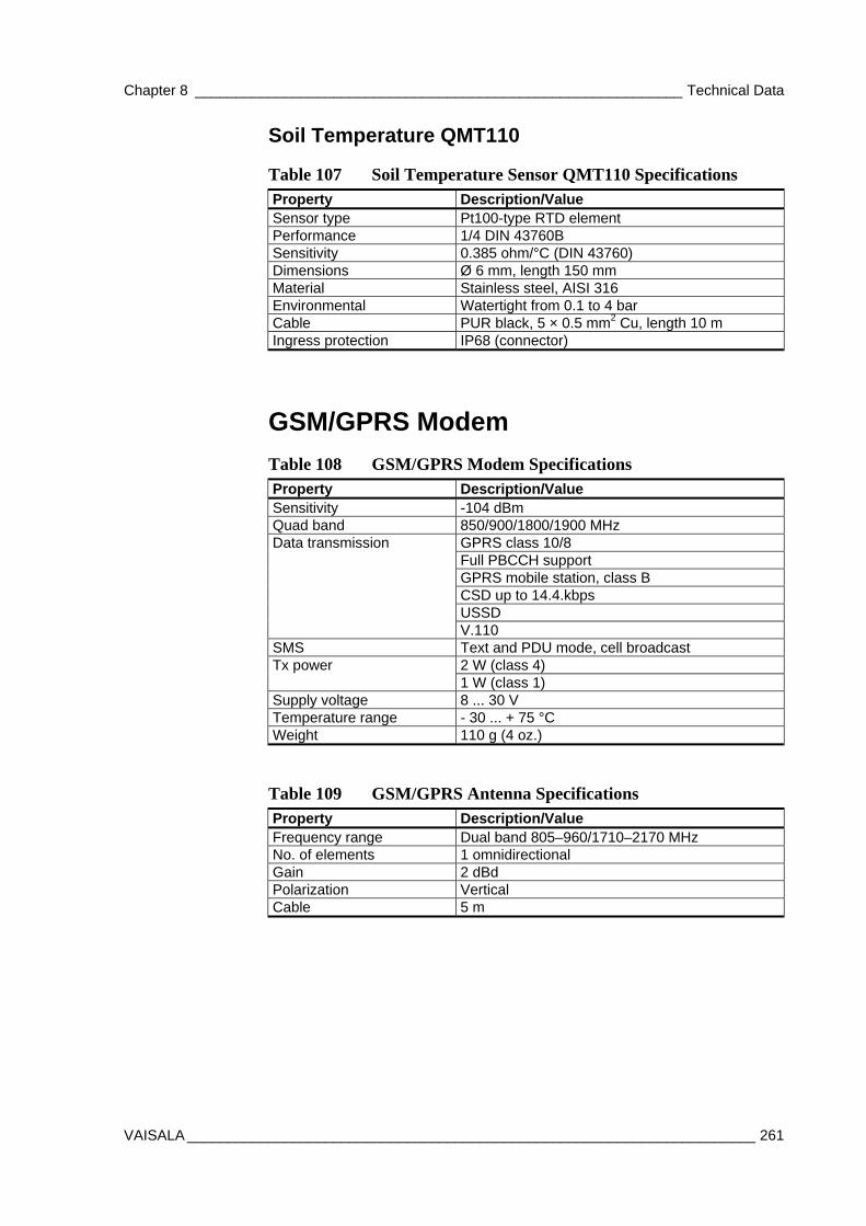
Chapter 8 ____________________________________________________________ Technical Data
VAISALA ______________________________________________________________________ 261
Soil Temperature QMT110
Table 107 Soil Temperature Sensor QMT110 Specifications Property Description/Value Sensor type Pt100-type RTD element Performance 1/4 DIN 43760B Sensitivity 0.385 ohm/°C (DIN 43760) Dimensions Ø 6 mm, length 150 mm Material Stainless steel, AISI 316 Environmental Watertight from 0.1 to 4 bar Cable PUR black, 5 × 0.5 mm2 Cu, length 10 m Ingress protection IP68 (connector)
GSM/GPRS Modem
Table 108 GSM/GPRS Modem Specifications Property Description/Value Sensitivity -104 dBm Quad band 850/900/1800/1900 MHz
GPRS class 10/8 Full PBCCH support GPRS mobile station, class B CSD up to 14.4.kbps USSD
Data transmission
V.110 SMS Text and PDU mode, cell broadcast
2 W (class 4) Tx power 1 W (class 1)
Supply voltage 8 ... 30 V Temperature range - 30 ... + 75 °C Weight 110 g (4 oz.)
Table 109 GSM/GPRS Antenna Specifications
Property Description/Value Frequency range Dual band 805–960/1710–2170 MHz No. of elements 1 omnidirectional Gain 2 dBd Polarization Vertical Cable 5 m

User's Guide ______________________________________________________________________
262 _________________________________________________________________ M211296EN-A
This page intentionally left blank.

Appendix A __________________________________________________________ Wiring Diagrams
VAISALA ______________________________________________________________________ 263
APPENDIX A
WIRING DIAGRAMS
This chapter contains the wiring diagrams for AWS330.
AWS330 System Basic Wiring Diagrams
The following pages contain the wiring diagrams for the AWS330 system:
- DRW235810, Block diagram
- DRW235936, Power and display
- DRW235937, Data lines
- DRW235938, Wind sensors
- DRW235939, Sensor connections
- DRW235992, Sensor cables
- DRW235993, Connector flange
- DRW236056, AWS330 Enclosure Layout, Cover installation plates
- DRW236056, AWS330 Enclosure Layout, Inside view
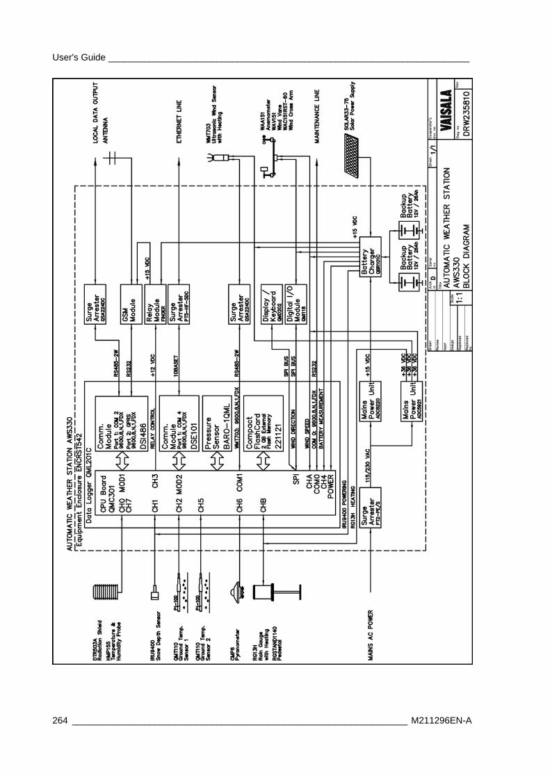
User's Guide ______________________________________________________________________
264 _________________________________________________________________ M211296EN-A
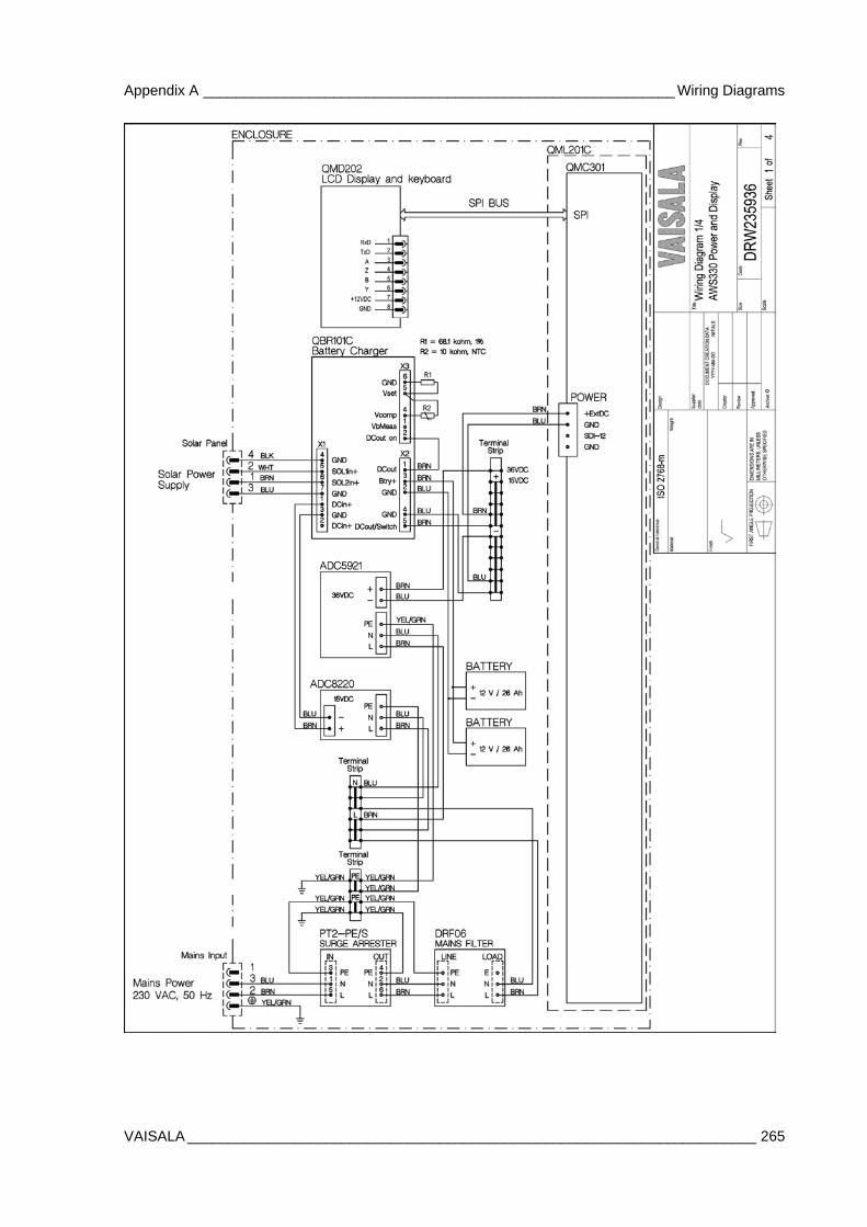
Appendix A __________________________________________________________ Wiring Diagrams
VAISALA ______________________________________________________________________ 265
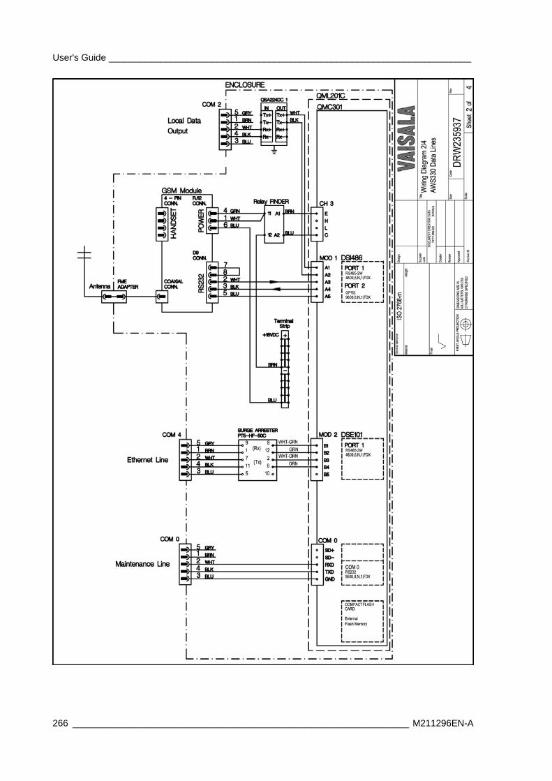
User's Guide ______________________________________________________________________
266 _________________________________________________________________ M211296EN-A
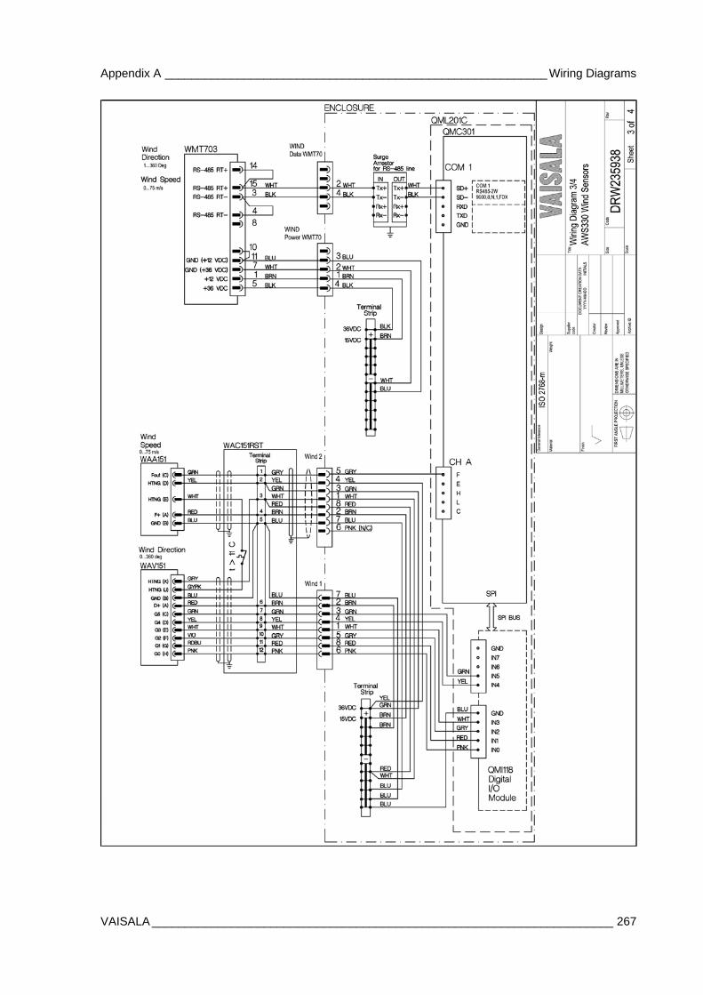
Appendix A __________________________________________________________ Wiring Diagrams
VAISALA ______________________________________________________________________ 267
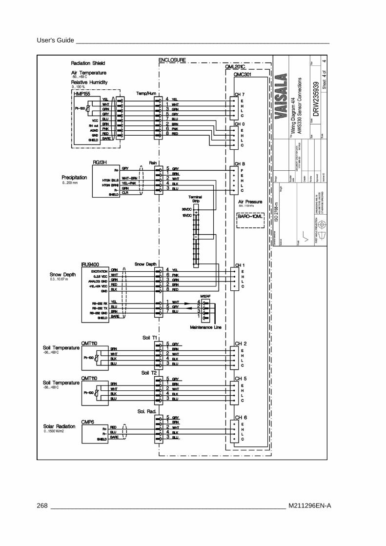
User's Guide ______________________________________________________________________
268 _________________________________________________________________ M211296EN-A
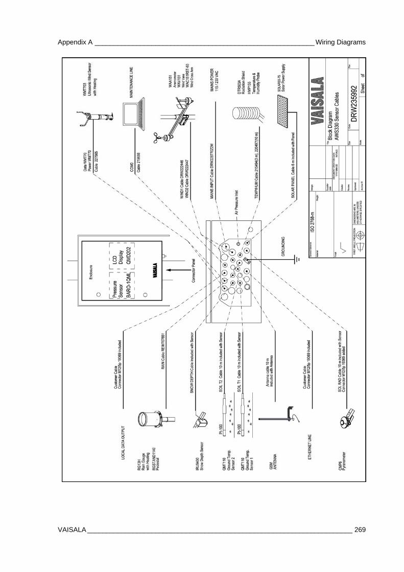
Appendix A __________________________________________________________ Wiring Diagrams
VAISALA ______________________________________________________________________ 269
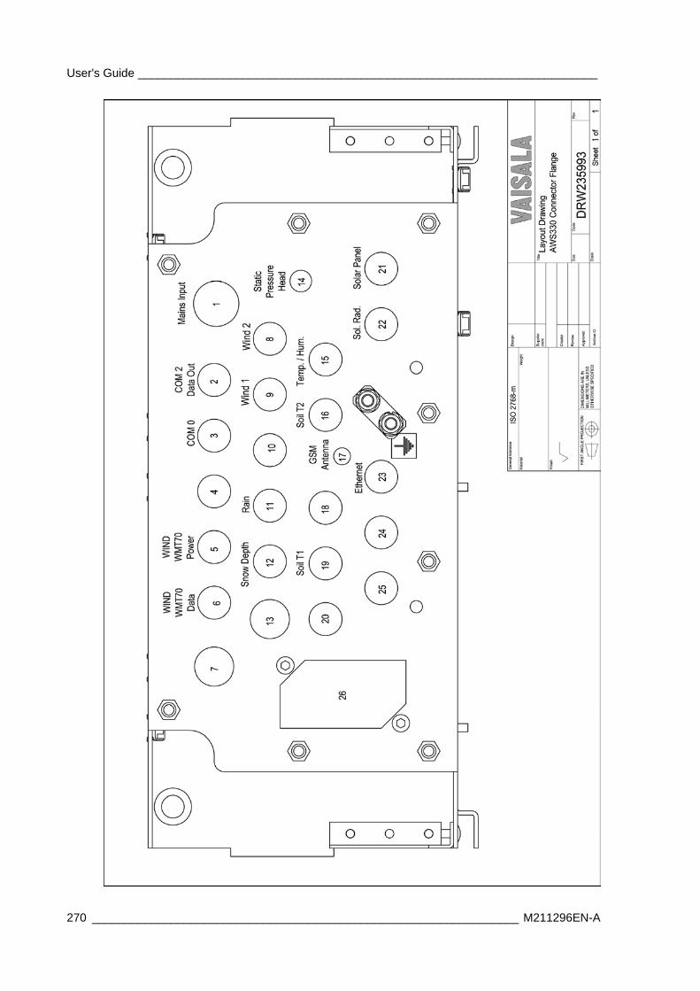
User's Guide ______________________________________________________________________
270 _________________________________________________________________ M211296EN-A
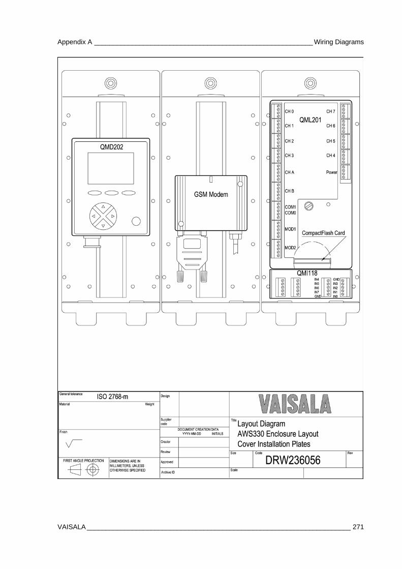
Appendix A __________________________________________________________ Wiring Diagrams
VAISALA ______________________________________________________________________ 271
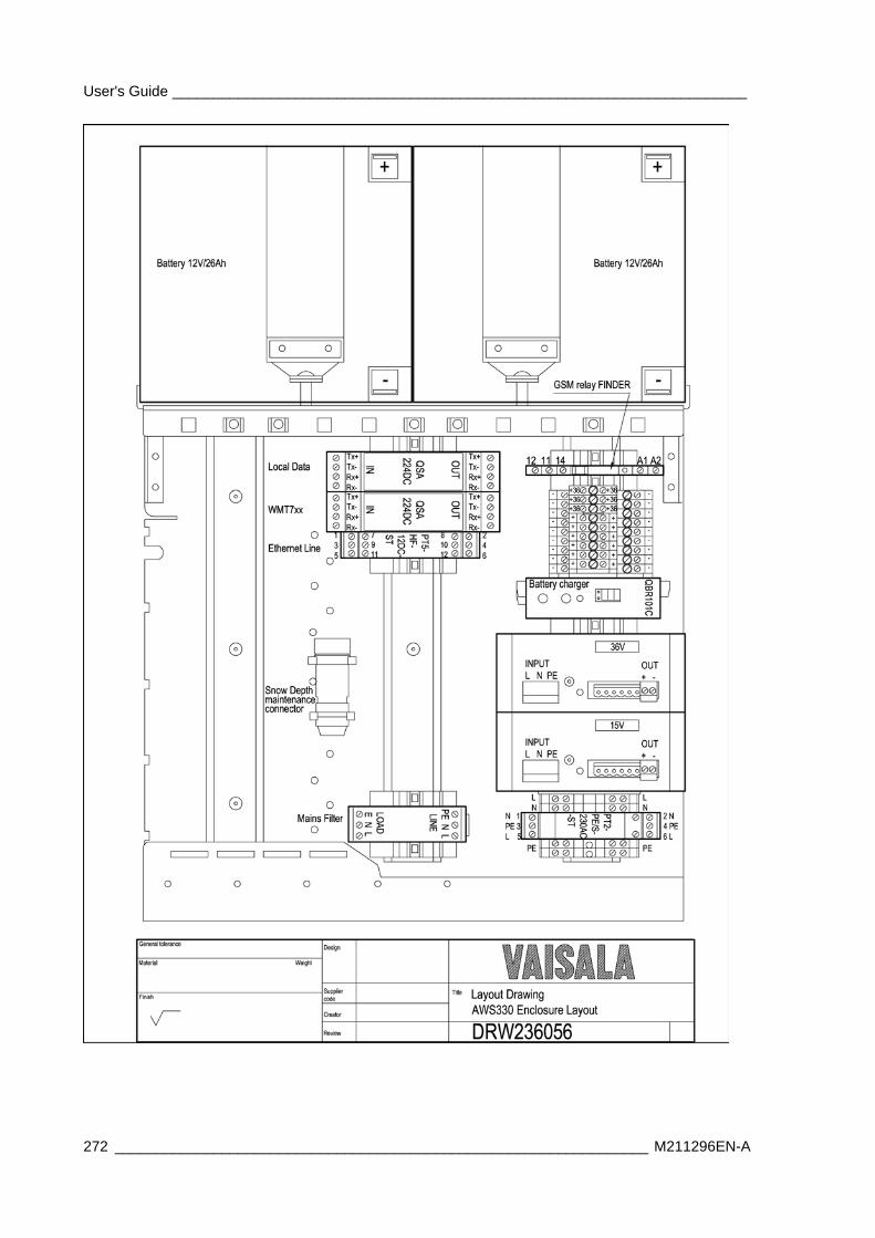
User's Guide ______________________________________________________________________
272 _________________________________________________________________ M211296EN-A
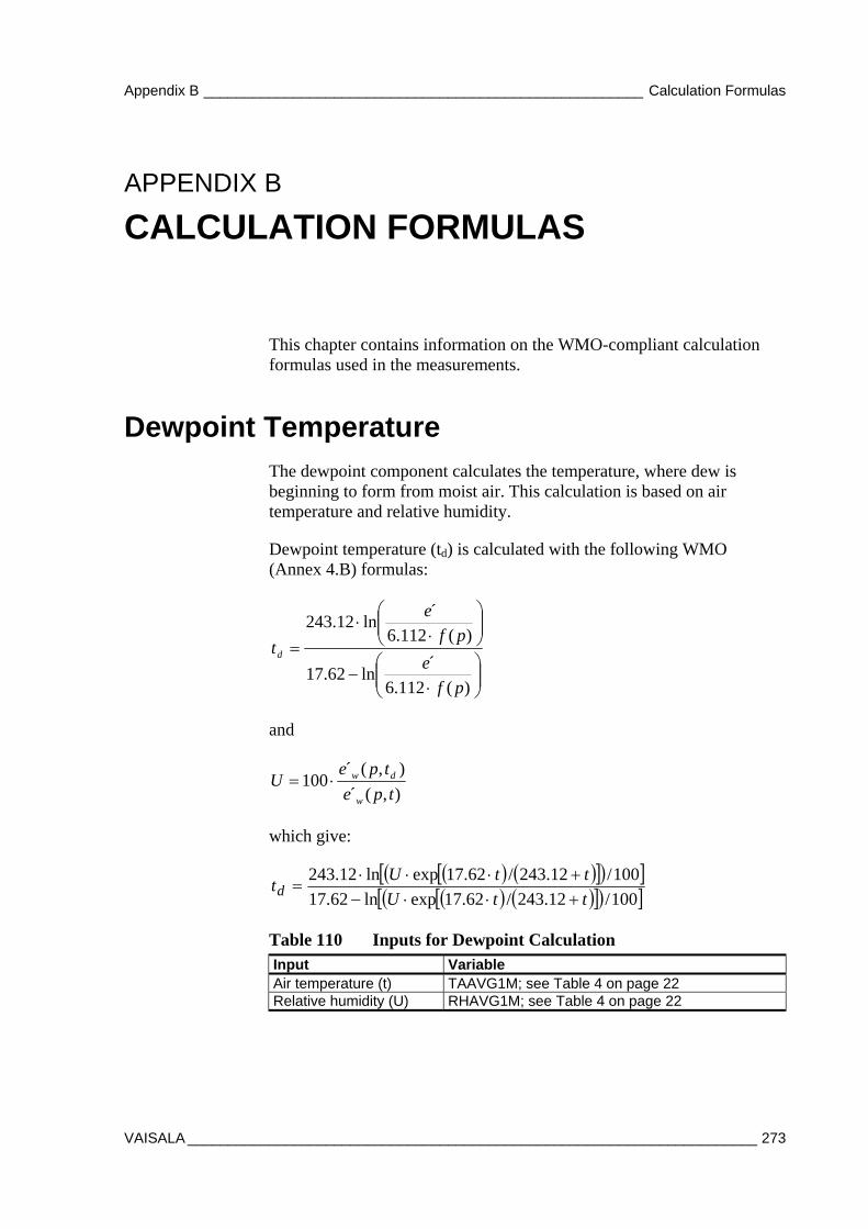
Appendix B ______________________________________________________ Calculation Formulas
VAISALA ______________________________________________________________________ 273
APPENDIX B
CALCULATION FORMULAS
This chapter contains information on the WMO-compliant calculation formulas used in the measurements.
Dewpoint Temperature The dewpoint component calculates the temperature, where dew is beginning to form from moist air. This calculation is based on air temperature and relative humidity.
Dewpoint temperature (td) is calculated with the following WMO (Annex 4.B) formulas:
)(112.6
´ln62.17
)(112.6
´ln12.243
pf
e
pf
e
td
and
),(´
),(´100
tpe
tpeU
w
dw
which give:
100/12.243/62.17expln62.17
100/12.243/62.17expln12.243
ttU
ttUtd
Table 110 Inputs for Dewpoint Calculation Input Variable Air temperature (t) TAAVG1M; see Table 4 on page 22 Relative humidity (U) RHAVG1M; see Table 4 on page 22
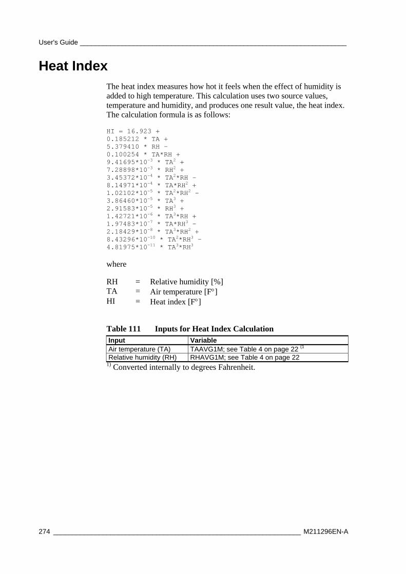
User's Guide ______________________________________________________________________
274 _________________________________________________________________ M211296EN-A
Heat Index The heat index measures how hot it feels when the effect of humidity is added to high temperature. This calculation uses two source values, temperature and humidity, and produces one result value, the heat index. The calculation formula is as follows:
HI = 16.923 + 0.185212 * TA + 5.379410 * RH – 0.100254 * TA*RH + 9.41695*10-3 * TA2 + 7.28898*10-3 * RH2 + 3.45372*10-4 * TA2*RH – 8.14971*10-4 * TA*RH2 + 1.02102*10-5 * TA2*RH2 – 3.86460*10-5 * TA3 + 2.91583*10-5 * RH3 + 1.42721*10-6 * TA3*RH + 1.97483*10-7 * TA*RH3 – 2.18429*10-8 * TA3*RH2 + 8.43296*10-10 * TA2*RH3 – 4.81975*10-11 * TA3*RH3
where
RH = Relative humidity [%] TA = Air temperature [F] HI = Heat index [F]
Table 111 Inputs for Heat Index Calculation Input Variable Air temperature (TA) TAAVG1M; see Table 4 on page 22 (1 Relative humidity (RH) RHAVG1M; see Table 4 on page 22
1) Converted internally to degrees Fahrenheit.
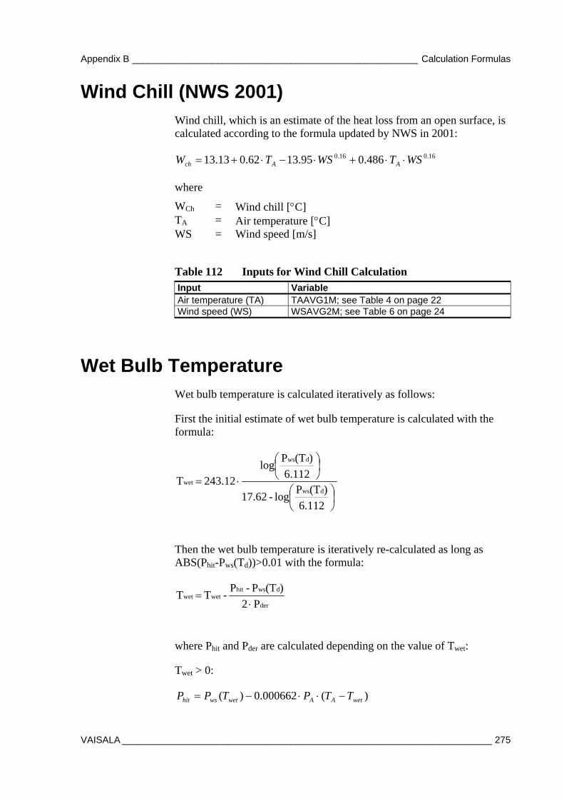
Appendix B ______________________________________________________ Calculation Formulas
VAISALA ______________________________________________________________________ 275
Wind Chill (NWS 2001) Wind chill, which is an estimate of the heat loss from an open surface, is calculated according to the formula updated by NWS in 2001:
16.016.0 486.095.1362.013.13 WSTWSTW AAch
where
WCh = Wind chill [C] TA = Air temperature [C] WS = Wind speed [m/s]
Table 112 Inputs for Wind Chill Calculation Input Variable Air temperature (TA) TAAVG1M; see Table 4 on page 22 Wind speed (WS) WSAVG2M; see Table 6 on page 24
Wet Bulb Temperature Wet bulb temperature is calculated iteratively as follows:
First the initial estimate of wet bulb temperature is calculated with the formula:
6.112
)(TPlog -17.62
6.112
)(TPlog
243.12 Tdws
dws
wet
Then the wet bulb temperature is iteratively re-calculated as long as ABS(Phit-Pws(Td))>0.01 with the formula:
P2
)(TP - P- T T
der
dwshitwetwet
where Phit and Pder are calculated depending on the value of Twet:
Twet > 0:
)(000662.0)( wetAAwetwshit TTPTPP
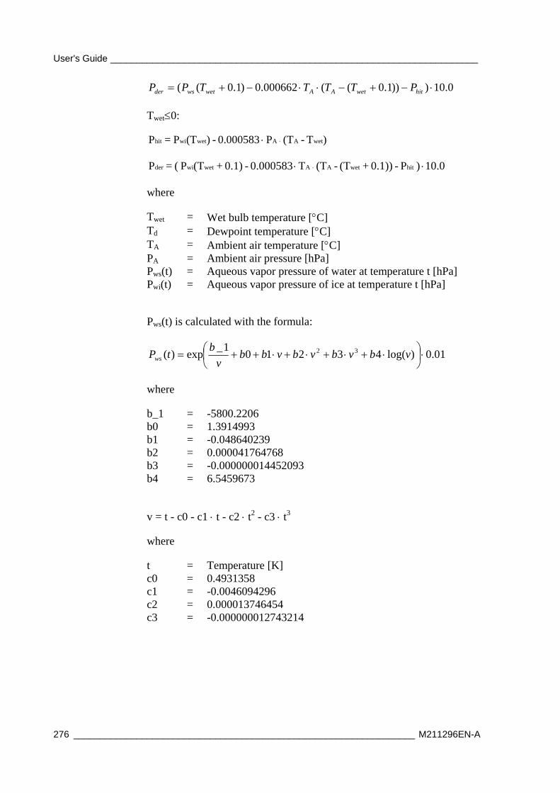
User's Guide ______________________________________________________________________
276 _________________________________________________________________ M211296EN-A
0.10)))1.0((000662.0)1.0(( hitwetAAwetwsder PTTTTPP
Twet0:
)T-(TP0.000583 - )(TP = P wetAAwetwihit
10.0) P - 0.1))+(T-(TT0.000583 - 0.1)+(TP ( = P hitwetAAwetwider
where
Twet = Wet bulb temperature [C] Td = Dewpoint temperature [C] TA = Ambient air temperature [C] PA = Ambient air pressure [hPa] Pws(t) = Aqueous vapor pressure of water at temperature t [hPa] Pwi(t) = Aqueous vapor pressure of ice at temperature t [hPa]
Pws(t) is calculated with the formula:
01.0)log(432101_
exp)( 32
vbvbvbvbb
v
btPws
where
b_1 = -5800.2206 b0 = 1.3914993 b1 = -0.048640239 b2 = 0.000041764768 b3 = -0.000000014452093 b4 = 6.5459673
v = t - c0 - c1 t - c2 t2 - c3 t3
where
t = Temperature [K] c0 = 0.4931358 c1 = -0.0046094296 c2 = 0.000013746454 c3 = -0.000000012743214
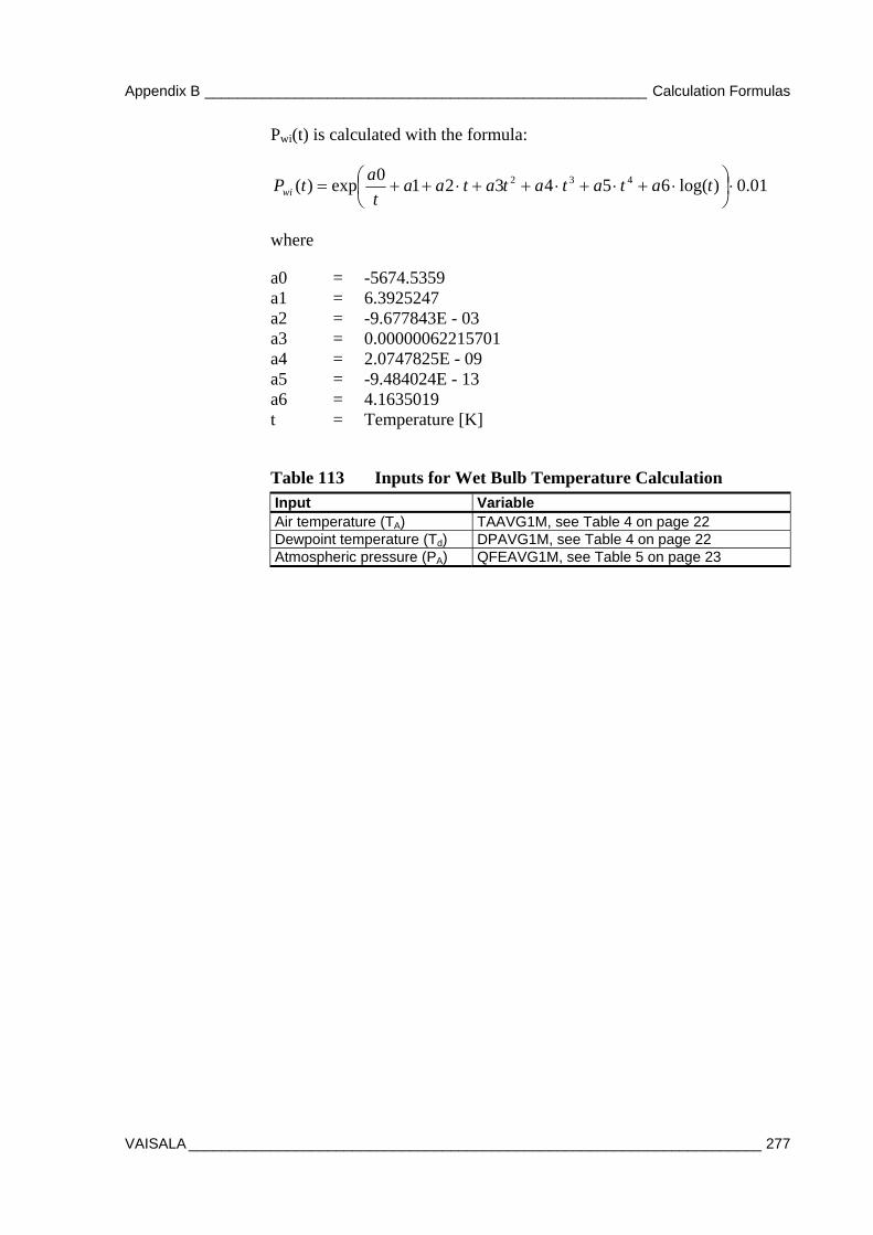
Appendix B ______________________________________________________ Calculation Formulas
VAISALA ______________________________________________________________________ 277
Pwi(t) is calculated with the formula:
01.0)log(6543210
exp)( 432
tatatatataa
t
atPwi
where
a0 = -5674.5359 a1 = 6.3925247 a2 = -9.677843E - 03 a3 = 0.00000062215701 a4 = 2.0747825E - 09 a5 = -9.484024E - 13 a6 = 4.1635019 t = Temperature [K]
Table 113 Inputs for Wet Bulb Temperature Calculation Input Variable Air temperature (TA) TAAVG1M, see Table 4 on page 22 Dewpoint temperature (Td) DPAVG1M, see Table 4 on page 22 Atmospheric pressure (PA) QFEAVG1M, see Table 5 on page 23
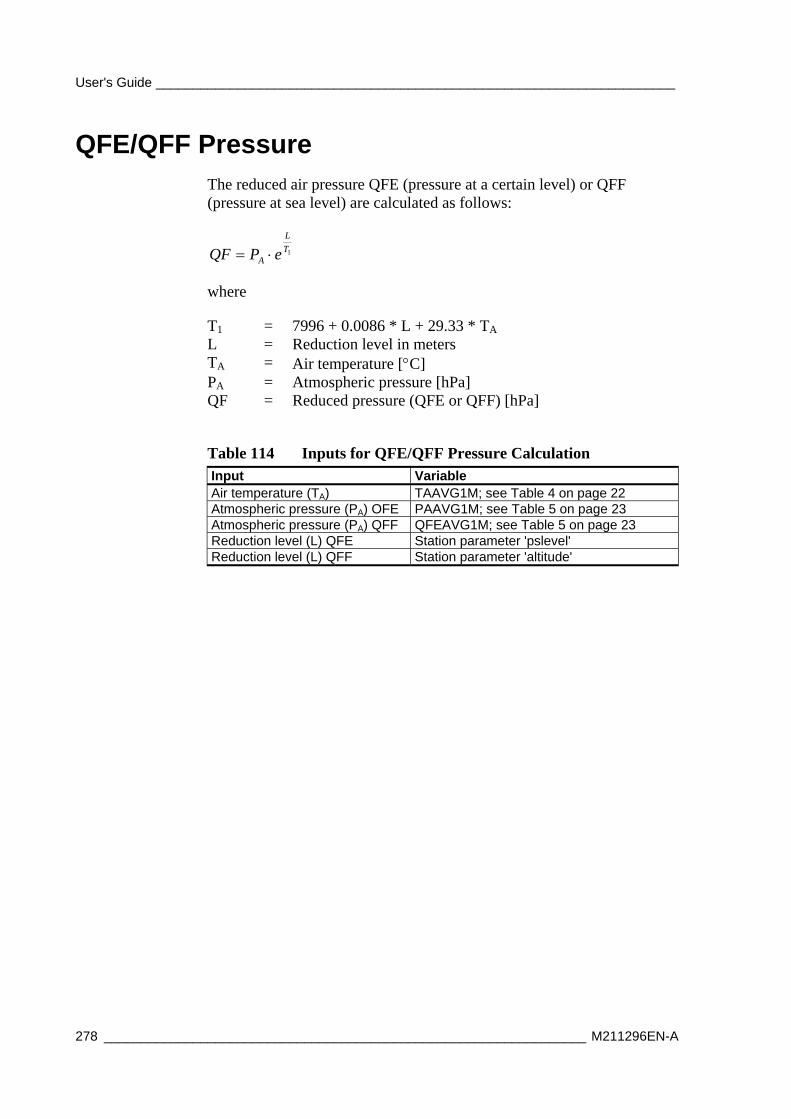
User's Guide ______________________________________________________________________
278 _________________________________________________________________ M211296EN-A
QFE/QFF Pressure The reduced air pressure QFE (pressure at a certain level) or QFF (pressure at sea level) are calculated as follows:
1T
L
A ePQF
where
T1 = 7996 + 0.0086 * L + 29.33 * TA L = Reduction level in meters TA = Air temperature [C] PA = Atmospheric pressure [hPa] QF = Reduced pressure (QFE or QFF) [hPa]
Table 114 Inputs for QFE/QFF Pressure Calculation Input Variable Air temperature (TA) TAAVG1M; see Table 4 on page 22 Atmospheric pressure (PA) OFE PAAVG1M; see Table 5 on page 23 Atmospheric pressure (PA) QFF QFEAVG1M; see Table 5 on page 23 Reduction level (L) QFE Station parameter 'pslevel' Reduction level (L) QFF Station parameter 'altitude'
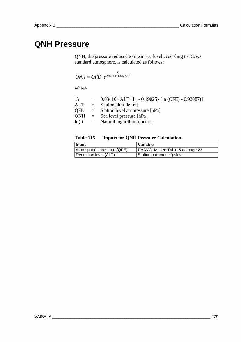
Appendix B ______________________________________________________ Calculation Formulas
VAISALA ______________________________________________________________________ 279
QNH Pressure QNH, the pressure reduced to mean sea level according to ICAO standard atmosphere, is calculated as follows:
ALT
T
eQFEQNH 00325.02.2881
where
T1 = 0.03416 ALT [1 - 0.19025 (ln (QFE) - 6.92087)] ALT = Station altitude [m] QFE = Station level air pressure [hPa] QNH = Sea level pressure [hPa] ln( ) = Natural logarithm function
Table 115 Inputs for QNH Pressure Calculation Input Variable Atmospheric pressure (QFE) PAAVG1M; see Table 5 on page 23 Reduction level (ALT) Station parameter 'pslevel'
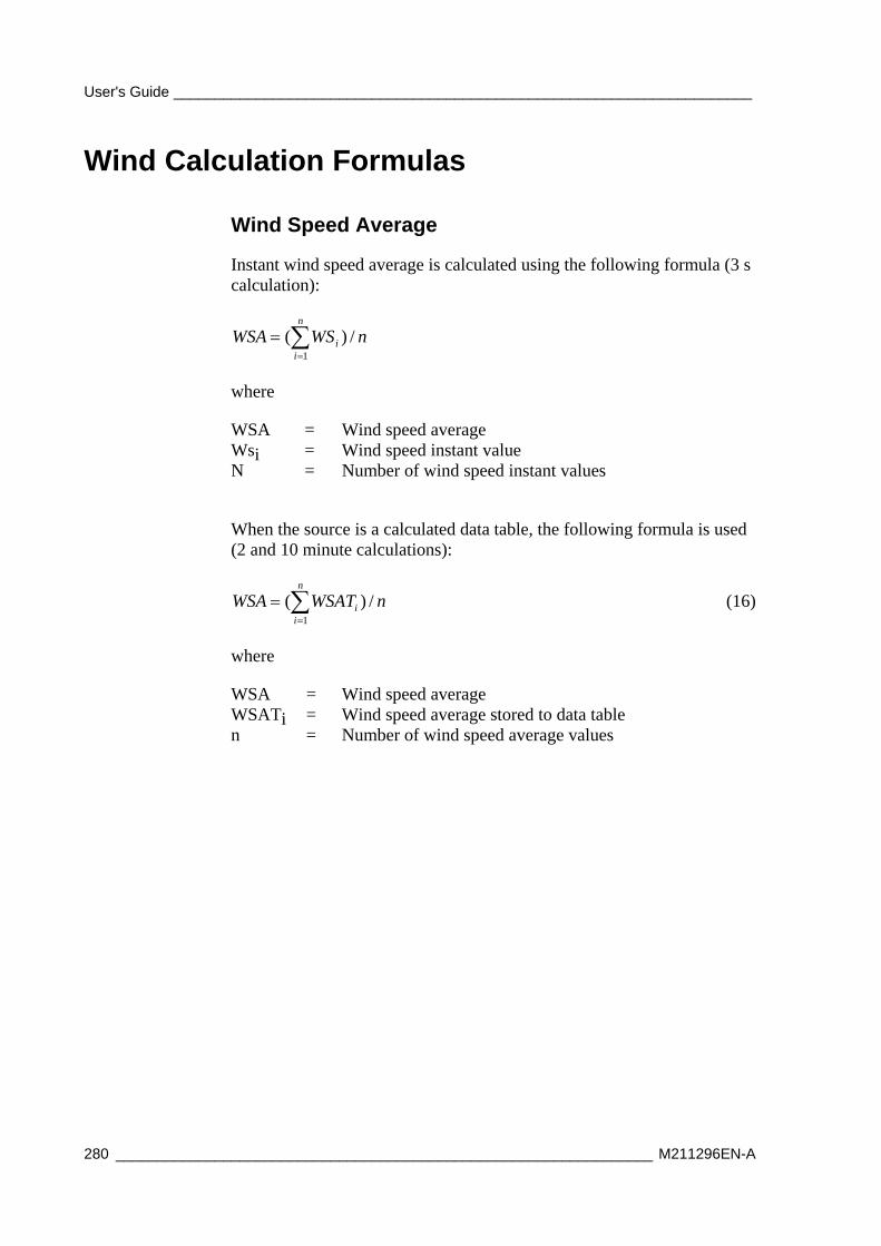
User's Guide ______________________________________________________________________
280 _________________________________________________________________ M211296EN-A
Wind Calculation Formulas
Wind Speed Average
Instant wind speed average is calculated using the following formula (3 s calculation):
n
ii nWSWSA
1
/)(
where
WSA = Wind speed average Wsi = Wind speed instant value N = Number of wind speed instant values
When the source is a calculated data table, the following formula is used (2 and 10 minute calculations):
n
ii nWSATWSA
1
/)( (16)
where
WSA = Wind speed average WSATi = Wind speed average stored to data table n = Number of wind speed average values
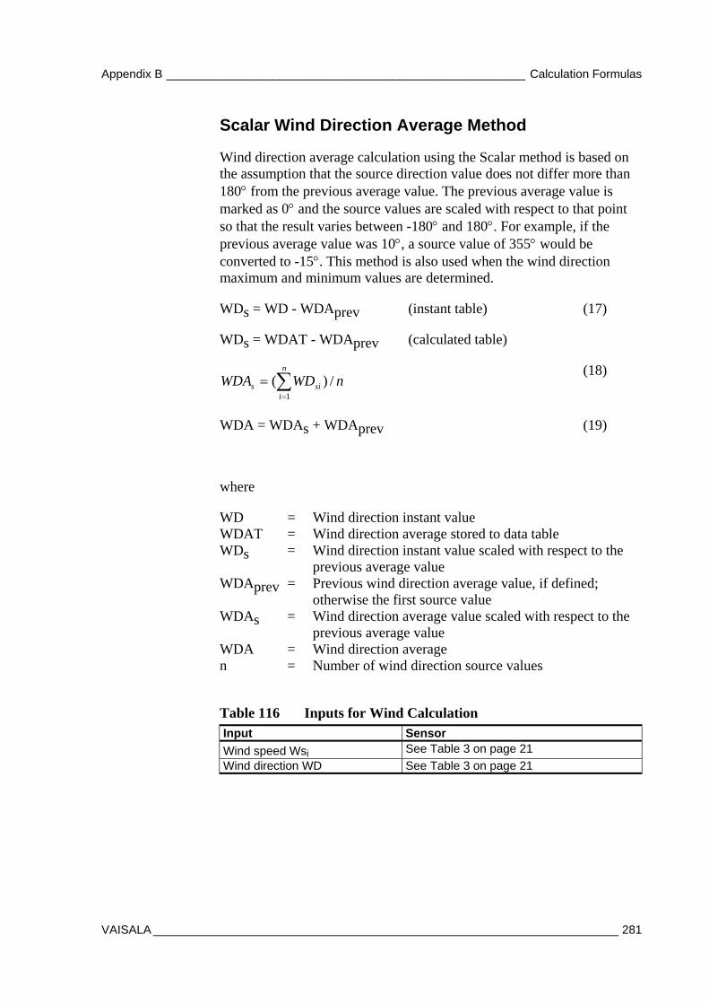
Appendix B ______________________________________________________ Calculation Formulas
VAISALA ______________________________________________________________________ 281
Scalar Wind Direction Average Method
Wind direction average calculation using the Scalar method is based on the assumption that the source direction value does not differ more than 180 from the previous average value. The previous average value is marked as 0 and the source values are scaled with respect to that point so that the result varies between -180 and 180. For example, if the previous average value was 10, a source value of 355 would be converted to -15. This method is also used when the wind direction maximum and minimum values are determined.
WDs = WD - WDAprev (instant table) (17)
WDs = WDAT - WDAprev (calculated table)
n
isis nWDWDA
1
/)( (18)
WDA = WDAs + WDAprev (19)
where
WD = Wind direction instant value WDAT = Wind direction average stored to data table WDs = Wind direction instant value scaled with respect to the
previous average value WDAprev = Previous wind direction average value, if defined;
otherwise the first source value WDAs = Wind direction average value scaled with respect to the
previous average value WDA = Wind direction average n = Number of wind direction source values
Table 116 Inputs for Wind Calculation Input Sensor
Wind speed Wsi See Table 3 on page 21
Wind direction WD See Table 3 on page 21

User's Guide ______________________________________________________________________
282 _________________________________________________________________ M211296EN-A
Sunshine Duration Sunshine duration calculation reports whether the sun is shining or not. The sun is considered to be shining, if global radiation (G) is more than 120 W/m2. Also, the ratio G/G0, where G0 is the calculated extraterrestrial global radiation (on top of the atmosphere), must be over 0.4. Calculation of G0 requires stations position (longitude and latitude), current (= local) time, and day number (0-365).
The global radiation G is measured with a pyranometer (CM6B is recommended), using an analog measuring channel. Time and day number are composed using the QML logger internal time functions. Of course, user must set local time and time zone correctly to ensure proper operation.
Before G0 can be calculated, the zenith angle of the sun, at station location, must be less than 85 degrees. The G/G0 limit, zenith angle limit, and radiation limit are configurable.
The sunshine duration component returns Boolean-type data '1' if the sun is shining and '0' if it is not. This data is supposed to be logged by the QML logger or external system to retrieve a history of sunshine duration.
Calculation of Extraterrestrial Global Radiation G0
)cos(
)365
4sin000077.0
365
4cos000719.0
365
2cos034221.0
000110.1(13670
e
DN
DN
DN
G
where
DN = Day number (1-366) e = Zenith angle (-90.0 - 90.0 degrees) G0 = Extraterrestrial global radiation (0 - 1422 W/m2)
Calculation of Zenith Angle e
coscos)cos(sin)(arccos(sin LatLate
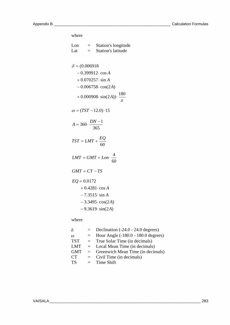
Appendix B ______________________________________________________ Calculation Formulas
VAISALA ______________________________________________________________________ 283
where
Lon = Station's longitude Lat = Station's latitude
180))2sin(000908.0
)2cos(006758.0
sin070257.0
cos399912.0
006918.0(
A
A
A
A
15)0.12( TST
365
1360
DNA
60
EQLMTTST
60
4 LonGMTLMT
TSCTGMT
)2sin(3619.9
)2cos(3495.3
sin3515.7
cos4281.0
0172.0
A
A
A
A
EQ
where
= Declination (-24.0 - 24.0 degrees) = Hour Angle (-180.0 - 180.0 degrees) TST = True Solar Time (in decimals) LMT = Local Mean Time (in decimals) GMT = Greenwich Mean Time (in decimals) CT = Civil Time (in decimals) TS = Time Shift

User's Guide ______________________________________________________________________
284 _________________________________________________________________ M211296EN-A
Table 117 Inputs for Sunshine Duration Calculation Input Variable Global radiation (G) GIRRAVG1M, see Table 9 on page 25 Latitude (Lat) Station parameter 'Latitude'; see section
Location Parameters on page 113 Longitude (Lon) Station parameter 'Longitude'; see section
Location Parameters on page 113
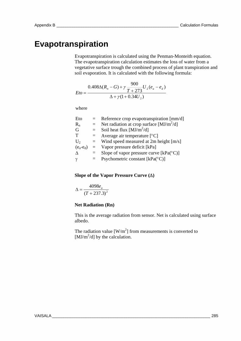
Appendix B ______________________________________________________ Calculation Formulas
VAISALA ______________________________________________________________________ 285
Evapotranspiration Evapotranspiration is calculated using the Penman-Monteith equation. The evapotranspiration calculation estimates the loss of water from a vegetative surface trough the combined process of plant transpiration and soil evaporation. It is calculated with the following formula:
)34.01(
)(273
900)(408.0
2
2
U
eeUT
GREto
dan
where
Eto = Reference crop evapotranspiration [mm/d] Rn = Net radiation at crop surface [MJ/m2/d] G = Soil heat flux [MJ/m2/d] T = Average air temperature [C] U2 = Wind speed measured at 2m height [m/s] (ea-ed) = Vapor pressure deficit [kPa] = Slope of vapor pressure curve [kPa(C)] = Psychometric constant [kPa(C)]
Slope of the Vapor Pressure Curve ()
2)3.237(
4098
T
ea
Net Radiation (Rn)
This is the average radiation from sensor. Net is calculated using surface albedo.
The radiation value [W/m2] from measurements is converted to [MJ/m2/d] by the calculation.
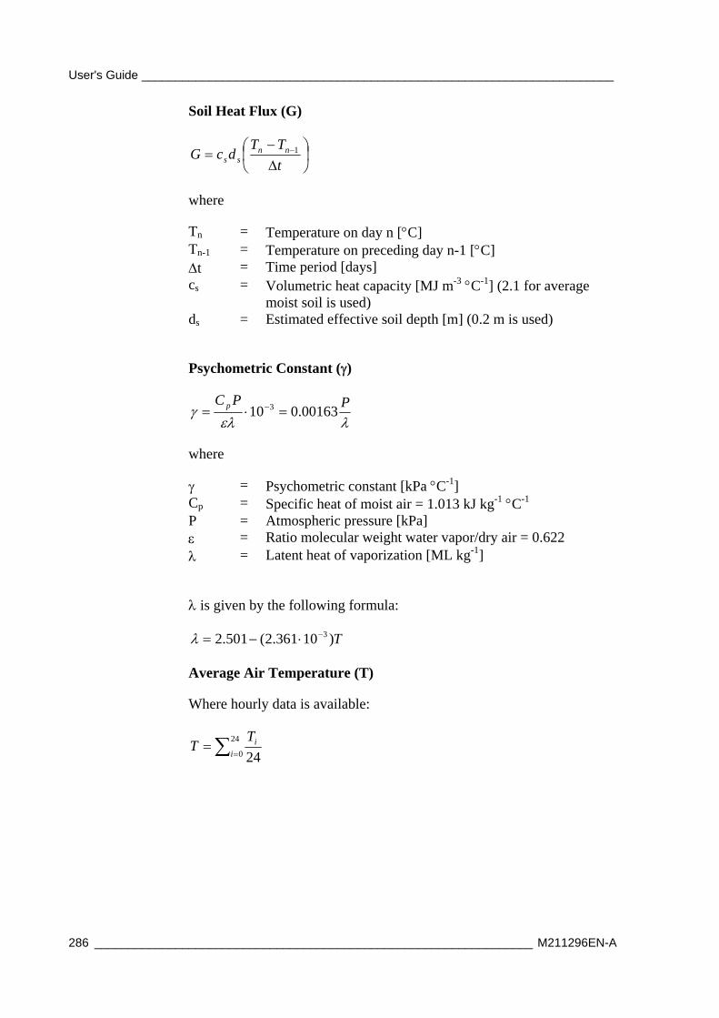
User's Guide ______________________________________________________________________
286 _________________________________________________________________ M211296EN-A
Soil Heat Flux (G)
t
TTdcG nn
ss1
where
Tn = Temperature on day n [C] Tn-1 = Temperature on preceding day n-1 [C] t = Time period [days] cs = Volumetric heat capacity [MJ m-3 C-1] (2.1 for average
moist soil is used) ds = Estimated effective soil depth [m] (0.2 m is used)
Psychometric Constant ()
PPC p 00163.010 3
where
= Psychometric constant [kPa C-1] Cp = Specific heat of moist air = 1.013 kJ kg-1 C-1 P = Atmospheric pressure [kPa] = Ratio molecular weight water vapor/dry air = 0.622 = Latent heat of vaporization [ML kg-1]
is given by the following formula:
T)10361.2(501.2 3
Average Air Temperature (T)
Where hourly data is available:
24
0 24i
iTT
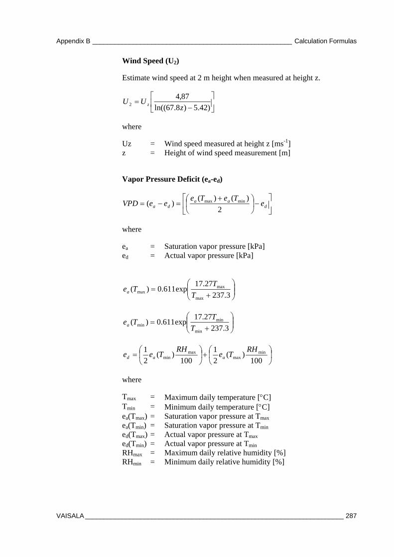
Appendix B ______________________________________________________ Calculation Formulas
VAISALA ______________________________________________________________________ 287
Wind Speed (U2)
Estimate wind speed at 2 m height when measured at height z.
)42.5)8.67ln((
87,42 z
UU z
where
Uz = Wind speed measured at height z [ms-1] z = Height of wind speed measurement [m]
Vapor Pressure Deficit (ea-ed)
daa
da eTeTe
eeVPD2
)()()( minmax
where
ea = Saturation vapor pressure [kPa] ed = Actual vapor pressure [kPa]
3.237
27.17exp611.0)(
max
maxmax T
TTea
3.237
27.17exp611.0)(
min
minmin T
TTea
100)(
2
1
100)(
2
1 minmax
maxmin
RHTe
RHTee aad
where
Tmax = Maximum daily temperature [C] Tmin = Minimum daily temperature [C] ea(Tmax) = Saturation vapor pressure at Tmax ea(Tmin) = Saturation vapor pressure at Tmin ed(Tmax) = Actual vapor pressure at Tmax ed(Tmin) = Actual vapor pressure at Tmin RHmax = Maximum daily relative humidity [%] RHmin = Minimum daily relative humidity [%]
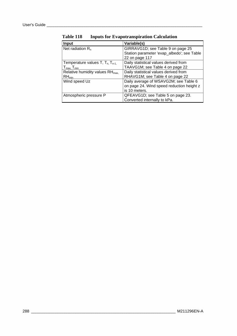
User's Guide ______________________________________________________________________
288 _________________________________________________________________ M211296EN-A
Table 118 Inputs for Evapotranspiration Calculation Input Variable(s) Net radiation Rn GIRRAVG1D; see Table 9 on page 25
Station parameter 'evap_albedo'; see Table 22 on page 117
Temperature values T, Tn, Tn-1, Tmax, Tmin
Daily statistical values derived from TAAVG1M; see Table 4 on page 22
Relative humidity values RHmax,
RHmin Daily statistical values derived from RHAVG1M; see Table 4 on page 22
Wind speed Uz Daily average of WSAVG2M; see Table 6 on page 24. Wind speed reduction height z is 10 meters.
Atmospheric pressure P QFEAVG1D; see Table 5 on page 23. Converted internally to kPa.

Appendix C _______________________________________________________ Example Messages
VAISALA ______________________________________________________________________ 289
APPENDIX C
EXAMPLE MESSAGES
This chapter contains example AWS330 messages.
CSV Message Note: The actual message does not contain linefeeds.
(S:AWS330;D:101129;T:061200;TAAVG1M:0.3;TAAVG1H:0.1; TAAVG1D:-0.3;TAMIN1D:-0.6;TAMAX1D:2.3;RHAVG1M:67; RHAVG1H:56;DPAVG1H:-7.4;DPAVG1M:-5.2;TBAVG1M:1.1; TBAVG1H:-2.2;HIAVG1M:0.3;WCHAVG1M:2.0; QFEAVG1M:1018.3;QFEAVG1H:1017.4;QFEMIN1H:1014.4; QFEMAX1H:1020.1;QFEAVG1D:1020.1;QFEMIN1D:1020.1; QFEMAX1D:1020.2;QFFAVG1M:1020.3;QFFAVG1H:1020.4; QFFMIN1H:1020.4;QFFMAX1H:1020.1;QFFMIN1D:1020.1; QFFAVG1D:1020.1;QFFMAX1D:1020.2;QNHAVG1M:1018.3; QNHAVG1H:1018.4;QNHMIN1H:1018.4;QNHMAX1H:1018.1; QNHAVG1D:1017.3;QNHMIN1D:1017.1;QNHMAX1D:1018.3; PTREND3H:1.8;PTEND3H:0;VPAVG1H:3.4;WS:0.9;WD:60; WDAVG2M:74;WDMIN2M:60;WDMAX2M:80;WSAVG2M:1.8; WSMIN2M:0.1;WSMAX2M:4.1;WDAVG10M:63;WDMIN10M:45; WDMAX10M:80;WSAVG10M:2.0;WSMIN10M:0.0;WSMAX10M:4.2;WDWSMAX10M:53;PRSUM1M:0.0;PRSUM10M:0.0; PRSUM30M:0.0; PRSUM1H:0.0;PRSUM3H:0.0;PRSUM6H:0.0; PRSUM12H:0.0;PRSUM1D:0.0;PRFSUM1H:0.0;SNAVG1H:1274.8; TS1AVG10M:-1.3;TS1AVG1H:-2.6;TS1MIN1H:-5.1;TS1MAX1H:0.0; TS1AVG1D:-2.6;TS1MIN1D:-5.0;TS1MAX1D:-0.1;TS2AVG10M:-3.6; TS2AVG1H:-4.5;TS2MIN1H:-4.5; TS2MAX1H:-2.8;TS2AVG1D:-4.5; TS2MIN1D:-6.3;TS2MAX1D:2.7;GIRRAVG1M:700; GIRRAVG1H:525;GIRRAVG1D:525;SDUR1D:244;EVAP1D:1.5; UPTIME:18200;STATUS:0;EXTDC:10.7)
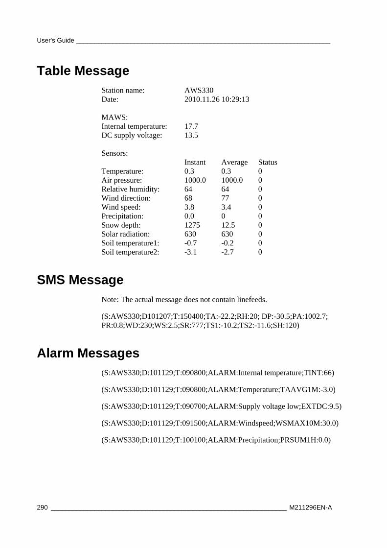
User's Guide ______________________________________________________________________
290 _________________________________________________________________ M211296EN-A
Table Message Station name: AWS330 Date: 2010.11.26 10:29:13 MAWS: Internal temperature: 17.7 DC supply voltage: 13.5 Sensors: Instant Average Status Temperature: 0.3 0.3 0 Air pressure: 1000.0 1000.0 0 Relative humidity: 64 64 0 Wind direction: 68 77 0 Wind speed: 3.8 3.4 0 Precipitation: 0.0 0 0 Snow depth: 1275 12.5 0 Solar radiation: 630 630 0 Soil temperature1: -0.7 -0.2 0 Soil temperature2: -3.1 -2.7 0
SMS Message Note: The actual message does not contain linefeeds.
(S:AWS330;D101207;T:150400;TA:-22.2;RH:20; DP:-30.5;PA:1002.7; PR:0.8;WD:230;WS:2.5;SR:777;TS1:-10.2;TS2:-11.6;SH:120)
Alarm Messages (S:AWS330;D:101129;T:090800;ALARM:Internal temperature;TINT:66)
(S:AWS330;D:101129;T:090800;ALARM:Temperature;TAAVG1M:-3.0)
(S:AWS330;D:101129;T:090700;ALARM:Supply voltage low;EXTDC:9.5)
(S:AWS330;D:101129;T:091500;ALARM:Windspeed;WSMAX10M:30.0)
(S:AWS330;D:101129;T:100100;ALARM:Precipitation;PRSUM1H:0.0)
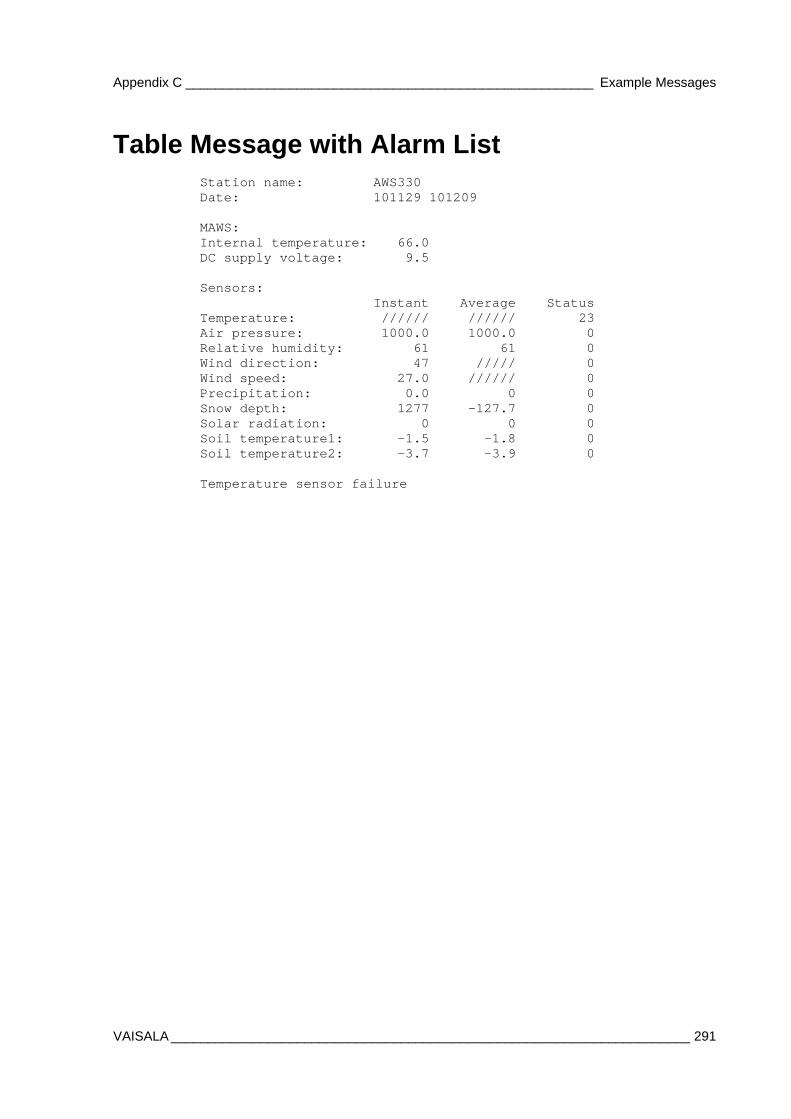
Appendix C _______________________________________________________ Example Messages
VAISALA ______________________________________________________________________ 291
Table Message with Alarm List Station name: AWS330 Date: 101129 101209 MAWS: Internal temperature: 66.0 DC supply voltage: 9.5 Sensors: Instant Average Status Temperature: ////// ////// 23 Air pressure: 1000.0 1000.0 0 Relative humidity: 61 61 0 Wind direction: 47 ///// 0 Wind speed: 27.0 ////// 0 Precipitation: 0.0 0 0 Snow depth: 1277 -127.7 0 Solar radiation: 0 0 0 Soil temperature1: -1.5 -1.8 0 Soil temperature2: -3.7 -3.9 0 Temperature sensor failure

User's Guide ______________________________________________________________________
292 _________________________________________________________________ M211296EN-A
This page intentionally left blank.
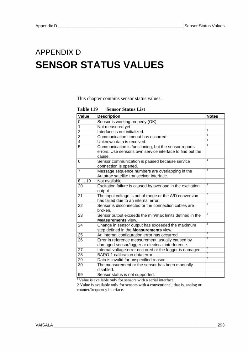
Appendix D ______________________________________________________ Sensor Status Values
VAISALA ______________________________________________________________________ 293
APPENDIX D
SENSOR STATUS VALUES
This chapter contains sensor status values.
Table 119 Sensor Status List Value Description Notes 0 Sensor is working properly (OK). 1 Not measured yet. 2 Interface is not initialized. 1 3 Communication timeout has occurred. 1 4 Unknown data is received. 1 5 Communication is functioning, but the sensor reports
errors. Use sensor's own service interface to find out the cause.
1
6 Sensor communication is paused because service connection is opened.
1
7 Message sequence numbers are overlapping in the Autotrac satellite transceiver interface.
1
8 ... 19 Not available.
20 Excitation failure is caused by overload in the excitation output.
1
21 The input voltage is out of range or the A/D conversion has failed due to an internal error.
2
22 Sensor is disconnected or the connection cables are broken.
2
23 Sensor output exceeds the min/max limits defined in the Measurements view.
2
24 Change in sensor output has exceeded the maximum step defined in the Measurements view.
2
25 An internal configuration error has occurred. 2
26 Error in reference measurement, usually caused by damaged sensor/logger or electrical interference.
2
27 Internal voltage error occurred or the logger is damaged. 2
28 BARO-1 calibration data error. 2
29 Data is invalid for unspecified reason. 2
30 The measurement or the sensor has been manually disabled.
99 Sensor status is not supported.
1 Value is available only for sensors with a serial interface. 2 Value is available only for sensors with a conventional, that is, analog or counter/frequency interface.

www.vaisala.com
*M211296EN*