Embed Size (px)
Citation preview
NCHRP Project 14-35
G-1
APPENDIX G 4977
AWS D1.5:2015 ANNEX K MARKUPS 4978
G.1 Annex K 4979
Annex K (Normative) 4980 Advanced Ultrasonic Examination 4981 4982 This annex is part of AWS D1.5M/D1.5:2015, Bridge Welding Code, and includes mandatory elements 4983
for use with this standard. 4984 4985 K1. Introduction 4986 This annex provides mandatory requirements that shall apply when phased array ultrasonic 4987
testing (PAUT) is used. The alternative techniques presented in this annex require written 4988 procedures, advanced operator training and qualification, and calibration methods specific to 4989 PAUT. 4990
4991 K2. Scope 4992 The procedures and standards set forth in this annex govern phased array examinations of groove 4993
welds (excluding tubular T-, Y-, and K-connection welds), including heat-affected zones (HAZ), 4994 for thicknesses between 5 mm and 100 mm [3/16 in and 4 in] using automatic data acquisition 4995 (encoded line scanning). 4996
4997 K3. Definitions 4998 4999 K3.1 Bandpass filtering. A function of the receiver circuit in most modern UT and PAUT 5000
equipment designed to filter out unwanted returned sound frequencies outside of that used for 5001 sound wave generation. The frequencies of sound on return are of much broader range than the 5002 range of frequencies put into the test piece. 5003
5004 K3.2 Channel. A send/receive circuit in the phased array unit. The number of channels dictates 5005
the maximum number of elements that the phased array unit can support as a whole. 5006 5007 K3.3 Dead elements. Individual elements that are no longer functional due to broken cables, 5008
connectors, or element failure. This can also include elements with substandard performance. 5009 5010 K3.4 E-Scan. A single focal law multiplexed across a grouping of active elements for a single 5011
beam angle that is stepped along the phased array probe length in defined incremental steps. 5012 5013 K3.5 Element. An individual crystal (piezo-composite material) within a phased array probe. 5014 5015

NCHRP Project 14-35
G-2
K3.6 Encoded. Done Performed with an encoder. 5016 5017 K3.7 Encoder. A device, normally in the form of a wheel or string, that records probe position 5018
for computer analysis for an automatic data acquisition system. 5019 5020 K3.8 Encoding. Using an encoder. 5021 5022 K3.9 Focal law. A phased array operational file defining search unit elements and time delays 5023
for transmitted and received signals. 5024 5025 K3.10 FSH. Full screen height. 5026 5027 K3.11 Imaging views. Images defined by different plane views between the ultrasonic path 5028
(ultrasonic axis), beam movement (index axis), and probe movement (scan axis) (see Figure K.1). 5029 Also called “scans” (see K3.11.1 ─ K3.11.5). 5030
5031 K3.11.1 A-Scan. A representation (view) of the received ultrasonic pulse amplitude versus time 5032
of flight in the ultrasonic path, also called a waveform. 5033 5034 K3.11.2 C-Scan. A 2-D plan or top view of the recorded A-scan data showing the beam 5035
movement (index axis) versus the probe movement (scan axis) path, using the maximum amplitude 5036 of the A scans at each transverse location. The C-scan may be presented in the volume-corrected 5037 or uncorrected form. 5038
5039 K3.11.3 Sectorial View. A 2D view of all A-scans from a specific set of elements corrected for 5040
delay and refracted angle. 5041 5042 K3.11.4 Side View. A 2-D view of the recorded A-scan data for one angle showing the 5043
ultrasonic path (ultrasonic axis) along the probe movement (scan axis) path. The A-scan amplitude 5044 is color coded. The side view may be presented in the volume-corrected or uncorrected form. 5045
5046 K3.11.5 End view. is aA 2-D view which is very similar to the side view. The end view is at 5047
90° to the side view and shows the ultrasonic path (ultrasonic axis) versus the beam movement 5048 axis (index axis). 5049
5050 K3.12 Line scan. The phased array scanning technique in which an E-scan, S-scan, or 5051
combination thereof is performed with the beams directed perpendicular to the weld, at a fixed 5052 distance from the welds, in a manner demonstrated to provide full weld coverage. Also called a 5053 linear scan. 5054
5055 K3.13 PAUT. Phased array ultrasonic testing. 5056 5057 K3.14 Phased array instrument. A multichannel test instrument used with multiple-element 5058
probes that enable the application of delay/focal laws when transmitting, and receiving, before 5059 summing. 5060
5061
NCHRP Project 14-35
G-3
K3.15 Phased array technique. A technique wherein UT data is generated by constructive 5062 phase interference formed by multiple elements controlled by accurate time delayed pulses. This 5063 technique can perform beam sweeping through an angular range (S-scans), beam scanning at fixed 5064 angle (E-scans), beam focusing, lateral scanning, and a variety of other scans depending on the 5065 array and programming. 5066
5067 K3.16 Phased array probe. A probe made up of several piezoelectric elements individually 5068
connected so that the signals they transmit or receive may be treated separately or combined as 5069 desired. The elements can be pulsed individually, simultaneously, or in a certain pattern relative 5070 to each other to create the desired beam angles or scan pattern. 5071
5072 K3.17 Pitch. The center to center distance between two successive phased array probe elements. 5073 5074 K3.18 Pulser. The instrument component that generates the electrical pulse. The number of 5075
pulsers dictates how many elements within a phased array probe may be applied within a given 5076 focal law. 5077
5078 K3.19 S-scan. The S-scan beam movement is a set of focal laws that provides a fan-like series 5079
of beams through a defined range of angles using the same set of elements. 5080 5081 K3.20 Saturated Signal. A signal in which the true peak amplitude cannot be measured in the 5082
stored data file due to bit depth of the phased array system. 5083 5084 K3.21 Scan plan. A document specifying key process elements such as equipment detail, focal 5085
law settings, and probe positions as necessary to complete an examination; also depicts weld and 5086 HAZ coverage. 5087
5088 K3.22 Scanner. A device used for holding the phased array probes in place while collecting 5089
data by means of an encoder. Scanners contain an encoder and may be automated or semi-5090 automated types as described below. 5091
5092 K3.22.1 Automated scanner. A mechanized device in which the PA probe movement is 5093
computerized or driven by remote control. 5094 5095 K3.22.2 Semi-Automated Scanner. A scanner that is manually driven along welds. 5096 5097 K3.23 Sound-path or depth calibration (horizontal linearity). A specific action used to 5098
compensate and adjust instrument time delay over all focal laws for specific wedge geometry for 5099 a depth or sound-path calibration. 5100
5101 K3.24 TCG. Time corrected gain. 5102 5103 K3.25 Time corrected gain (TCG). A calibration technique in which the search unit computes 5104
the dB gain difference needed to balance standard calibration reflectors (side drilled holes) at 5105 various material depths at one set screen amplitude. When completed, all side-drilled hole 5106 reflectors equal the same approximate amplitude regardless of their varying metal path distances. 5107
NCHRP Project 14-35
G-4
5108 K3.26 Virtual probe aperture (VPA). The number of elements in a phased array probe used 5109
for the examination. 5110 5111 K3.27 Volume-corrected scan. A presentation in which correction is made to the index axis A-5112
scan point locations based off true positional information relative to the beam angle or angles used 5113 during the inspection. 5114
5115 K3.28 VPA. Virtual probe aperture. 5116 5117 K4 Personnel Requirements. 5118 5119 K4.1 Personnel Qualification Requirements. Individuals who perform PAUT shall at a 5120
minimum be qualified for PAUT per 6.1.3.4. In satisfying the requirements of 6.1.3.4, the 5121 qualification of the PAUT operator shall include a specific and practical examination that shall be 5122 based on the requirements of this code. This examination shall require the PAUT operator to 5123 demonstrate the ability to apply the rules of this code in the accurate detection and disposition of 5124 discontinuities. 5125
5126 K4.2 Certification Requirements. Certification of Level II PAUT personnel shall be 5127
performed by an NDT UT Level III who both meets the requirements of 6.1.3.4 for PAUT and 5128 also has received a minimum of 80 hours of formal training in PAUT. A PAUT technician shall 5129 be deemed to be certified when the individual has: 5130
• Met the requirements in 6.1.3.4 for ASNT SNT-TC-1A as an NDT UT Level II including 5131 the Phased Array method. This includes, but not limited to, successful completion of the 5132 education, training, experience, and written examination prescribed in ASNT SNT-TC-5133 1A. 5134
• Successfully demonstrated through performance testing he or she is capable of: 5135 o Performing calibration, which includes accounting for the possible differences in 5136
acoustic properties between the calibration standard and the test piece used in the 5137 exam; 5138
o Developing scan plans for the test plates which meets the coverage requirements 5139 of this specification; 5140
o Reliably detecting and classifying known flaws according to this specification in 5141 the test plates; 5142
o Accurately reporting the results of the inspection of the test plates and 5143 documenting essential variables. 5144
5145 K5. Equipment 5146 5147 K5.1 Phased Array Instruments. Inspections shall be performed using phased array pulse-5148
echo equipment meeting the requirements of 6.15, qualified in accordance with K6. Phased array 5149 instruments shall also meet the following requirements: 5150
5151 K5.1.1 Number of Pulsers. The instrument shall be equipped with a minimum of 16 pulsers 5152
and channels (16:16 minimum). A minimum of 16:64 is required if E-scans are to be used. 5153

NCHRP Project 14-35
G-5
5154 K5.1.2 Imaging Views. The phased array instrument shall be equipped with sufficient display 5155
options, including A, C, sectorial and side views, and encoded scans, to provide thorough data 5156 analysis through the entire scan length and through all beams. 5157
5158 K5.2 Straight-Beam (Longitudinal Wave) Probes. The straight-beam (longitudinal wave) 5159
phased array probe shall produce frequencies in the range of 1 to 6 MHz. Probe dimensions shall 5160 be small enough that standing wave signals do not appear on the display. The phased array probe 5161 shall be a linear array probe capable of providing a resolution of three side drilled holes of the RC 5162 block. Alternatively, a UT search unit meeting the requirements of 6.15.6 may be used. 5163
5164 K5.3 Angle-Beam Search Units. Angle-beam search units shall consist of a phased array probe 5165
and an angle wedge to produce the desired refracted angles. 5166 5167 K5.3.1 Phased Array Probe. The probe shall be a linear array type with a minimum of 16 5168
elements. Nominal probe center and shall produce frequencies shall be between 1 2.25 MHz and 5169 6 5 MHz. Probe dimensions shall be chosen in order to optimize the beam formation within the 5170 area of the coverage. Difference in attenuation associated with different frequence probes must be 5171 accounted for during calibration. Probe pitch dimensions shall be small enough that standing wave 5172 signals do not appear on the display. 5173
5174 K5.3.2 Angled Phased Array Wedge. The wedge shall be of a sufficient incident angle to 5175
produce sound beams in the material between 45° 40° and 70° ±2°. Wedges shall be used within 5176 the angular range specified by the manufacturer. 5177
5178 K5.4 Encoder. The encoder shall be digital and capable of line scanning. 5179 5180 K5.5 Scanner. Encoding shall be performed by using a semi-automated or automated scanner 5181
as defined in K3.22. 5182 5183 K5.6 Couplant. A couplant material shall be used between the search unit and the test material. 5184
Any commercial couplant, water, or oil may be used when performing calibrations and 5185 examinations. The same couplant shall be used for calibration as for examination of the test object. 5186
5187 K5.7 Reference Standard for Determining SSL. The standard reflector used for test standard 5188
sensitivity level (SSL) shall be the 1.5 mm [0.06 in] diameter side drilled hole in an IIW block in 5189 conformance with ASTM E164, Standard Practice for Contact Ultrasonic Testing of Weldments. 5190
5191 K5.7 Calibration for Variation in Acoustic Properties. The following section includes 5192
requirements for calibration to account for differences in acoustic properties. 5193 5194 K5.7.1 Supplemental Calibration Block Geometric and Temperature Requirements. A 5195
supplemental The calibration block shall be used allowing allow for a minimum of a 3-point TCG 5196 establishment throughout the usable sound path range of all configured angles. The standard 5197 reflector used for setting the standard sensitivity level (SSL) shall be the 1.5 mm [0.06 in] diameter 5198 side drilled hole. A minimum spacing of 12.5 mm [0.5”] shall be provided between the center of 5199
NCHRP Project 14-35
G-6
the side drilled hole and the surface of the plate if TCG calibration will utilize sound propagation 5200 skipping off of the surface nearest to the hole. 5201
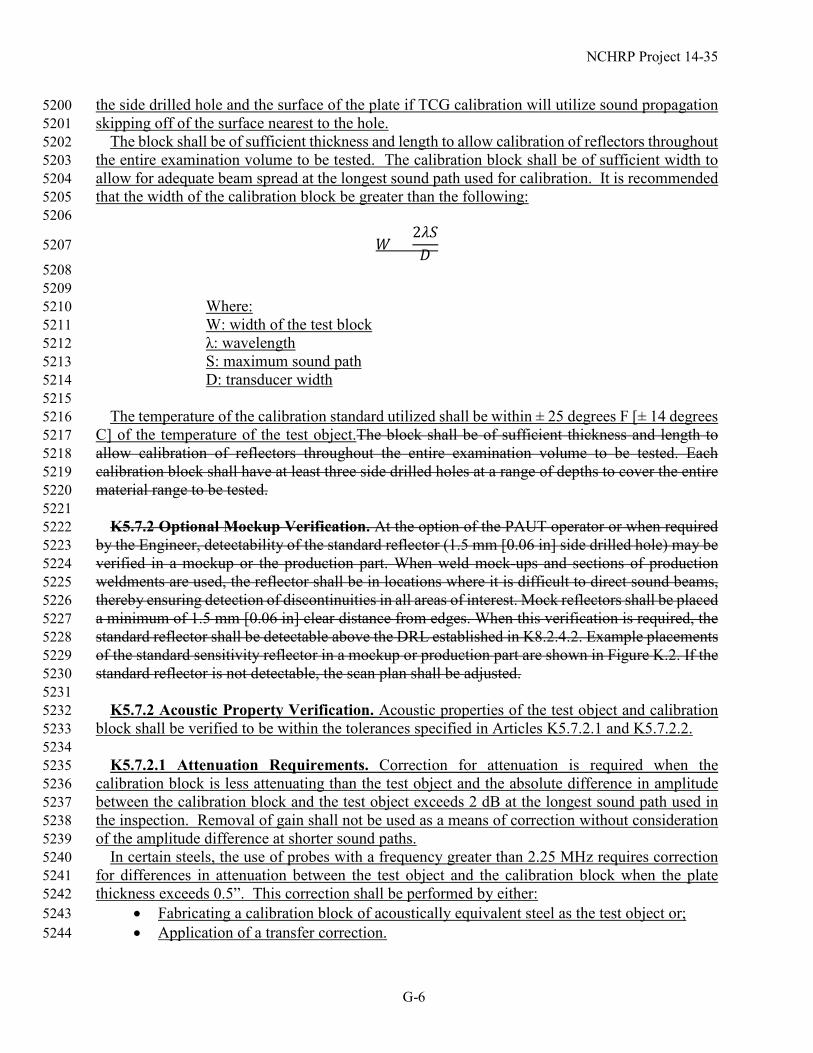
The block shall be of sufficient thickness and length to allow calibration of reflectors throughout 5202 the entire examination volume to be tested. The calibration block shall be of sufficient width to 5203 allow for adequate beam spread at the longest sound path used for calibration. It is recommended 5204 that the width of the calibration block be greater than the following: 5205
5206
𝑊𝑊 >2𝜆𝜆𝜆𝜆𝐷𝐷
5207
5208 5209 Where: 5210 W: width of the test block 5211 λ: wavelength 5212 S: maximum sound path 5213 D: transducer width 5214
5215 The temperature of the calibration standard utilized shall be within ± 25 degrees F [± 14 degrees 5216
C] of the temperature of the test object.The block shall be of sufficient thickness and length to 5217 allow calibration of reflectors throughout the entire examination volume to be tested. Each 5218 calibration block shall have at least three side drilled holes at a range of depths to cover the entire 5219 material range to be tested. 5220
5221 K5.7.2 Optional Mockup Verification. At the option of the PAUT operator or when required 5222
by the Engineer, detectability of the standard reflector (1.5 mm [0.06 in] side drilled hole) may be 5223 verified in a mockup or the production part. When weld mock-ups and sections of production 5224 weldments are used, the reflector shall be in locations where it is difficult to direct sound beams, 5225 thereby ensuring detection of discontinuities in all areas of interest. Mock reflectors shall be placed 5226 a minimum of 1.5 mm [0.06 in] clear distance from edges. When this verification is required, the 5227 standard reflector shall be detectable above the DRL established in K8.2.4.2. Example placements 5228 of the standard sensitivity reflector in a mockup or production part are shown in Figure K.2. If the 5229 standard reflector is not detectable, the scan plan shall be adjusted. 5230
5231 K5.7.2 Acoustic Property Verification. Acoustic properties of the test object and calibration 5232
block shall be verified to be within the tolerances specified in Articles K5.7.2.1 and K5.7.2.2. 5233 5234 K5.7.2.1 Attenuation Requirements. Correction for attenuation is required when the 5235
calibration block is less attenuating than the test object and the absolute difference in amplitude 5236 between the calibration block and the test object exceeds 2 dB at the longest sound path used in 5237 the inspection. Removal of gain shall not be used as a means of correction without consideration 5238 of the amplitude difference at shorter sound paths. 5239
In certain steels, the use of probes with a frequency greater than 2.25 MHz requires correction 5240 for differences in attenuation between the test object and the calibration block when the plate 5241 thickness exceeds 0.5”. This correction shall be performed by either: 5242
• Fabricating a calibration block of acoustically equivalent steel as the test object or; 5243 • Application of a transfer correction. 5244
NCHRP Project 14-35
G-7
If a transfer correction is selected, it shall be performed by a pitch-catch setup on the test object 5245 and calibration block. No correction is required if the greatest difference in amplitude between 5246 the calibration block and test object is 2 dB or less at the longest sound path. If the amplitude 5247 difference is greater than 2 dB but not greater than 12 dB, the difference may be compensated in 5248 the TCG gain. If the amplitude difference is greater than 12 dB, the roughness of the scanning 5249 surface of the test object shall either be reconditioned to better match the surface roughness of the 5250 calibration block or a calibration block which is more acoustically similar to the test object shall 5251 be used. 5252
5253 K5.7.2.2 Shear Wave Velocity Requirements. The shear wave velocity (vs) in the direction of 5254
sound propagation in the test object shall be measured and compared to the calibration block. 5255 Allowable incidence angles as a function of the percent difference in these velocities is given in 5256 Table K.1. 5257
When this difference exceeds 2.5%, calibration shall be performed using a different calibration 5258 block that is within 2.5% of the test object’s shear wave velocity in the direction of sound 5259 propagation. 5260 5261
K5.7.2.3 Acoustically Anisotropic Materials. It shall be verified the shear wave velocity in 5262 the rolling and transverse to rolling directions do not differ by more than 1%. Materials that have 5263 an anisotropic ratio (i.e., ratio of velocity in rolled and transverse to the rolling direction) of 1% or 5264 greater shall be defined as acoustically anisotropic. When inspecting acoustic anisotropic materials 5265 at an oblique orientation (i.e., neither parallel or perpendicular) to the rolling direction during line 5266 scanning or follow-up raster scanning the allowable incidence angles shall be limited to 40°-60° 5267 and +4 dB shall be added to the reference gain. 5268
5269 K5.7.2.4 Additional Requirements for ESW Welds. The amplitude and location associated 5270
with a 1.5 mm [0.06 in] diameter side drilled hole shall be measured and evaluated in a full-scale 5271 mockup of a portion of the weld using base metal of similar acoustic properties to the actual test 5272 object. The reflector shall be placed in a location which will maximize the sound path traveling 5273 through the weld metal. 5274
5275 K6. Equipment Qualification 5276 5277 K6.1 System Linearity. System linearity verifications shall be validated at a maximum of 12 5278
month intervals. Validation shall be performed as detailed in K14. 5279 5280 K6.2 Internal Reflections. Maximum internal reflections from each search unit shall be verified 5281
by the PAUT operator at a maximum time interval of 40 hours of instrument use and checked in 5282 accordance with 6.22.3. 5283
5284 K6.3 Resolution Requirements. Testing of the resolution of the combination of search unit and 5285
instrument shall be performed and documented per 6.16.3. 5286 5287 K6.4 Probe Operability Checks. An element operability check shall be performed by the 5288
PAUT operator prior to initial calibration and use and weekly on each phased array probe to 5289 determine if dead (inactive) or defective elements are present. No more than 10% of the elements 5290
NCHRP Project 14-35
G-8
may be dead and in a given aperture, and no more than two adjacent elements may be dead within 5291 a given aperture. This check shall also be performed upon each 8-hour period of use. In addition, 5292 each element within a phased array probe shall be evaluated to check for comparable amplitude 5293 responses throughout the aperture. Each element shall be verified to be within 6 dB of the element 5294 yielding the highest amplitude response. If the amplitude of any of the elements within the probe 5295 yields responses outside the 6 dB requirement, the element shall be declared dead. 5296
5297 K6.4.1 The probe operability check shall be performed by scanning through each element with 5298
the probe on the side of an IIW block or any reference block, and observing the back wall signal. 5299 5300 K7. Scan Plans 5301 5302 K7.1 Scan Plans. A scan plan, as defined in K3, shall be developed for the welds to be 5303
examined. The scan plan shall provide the specific attributes necessary to achieve examination 5304 coverage, including those variables subject to material and geometric variation that are not 5305 addressed in a general procedure. Scan plan contents shall consider all essential variables listed in 5306 Table K.52. 5307
5308 K7.1.1 The scan plan shall demonstrate by plotting or computer simulation the appropriate 5309
refracted angles to be used during the examination for the groove weld geometry and areas of 5310 concern with the requirements of K5.7.2 incorporated as needed. The scan plan shall demonstrate 5311 coverage of the required examination volume. Performance shall be verified through the 5312 calibration (i.e., beam index point and beam angle verifications). 5313
5314 K7.1.2 Whenever a scan plan is developed, values of essential variables shall be established and 5315
an initial calibration performed by a PAUT Level II or III to confirm adequate sound pressure 5316 throughout the configured ultrasonic range. A new calibration shall be required if an essential 5317 variable has changed. 5318
5319 K7.1.3 The scan plan shall document the examination volume covered. 5320 5321 K7.2 Focal Law Configuration. Focal laws shall be configured to provide the necessary 5322
coverage requirements stipulated in K7.4. Focal laws shall be created using 14 to a minimum of 5323 16 elements.; however, more elements may be used if additional penetration is shown to be needed 5324 during calibration. S-scans shall be used as the primary scan to optimize coverage and shall be 5325 configured in angular sweep increments of no greater than 1°. E-scans may be used as described 5326 below to supplement S-scans but shall not be used as a sole inspection technique. 5327
5328 K7.2.1 Index Positions. A sufficient number of index positions shall be configured to 5329
accomplish the coverage requirements of K7.4. These may be multiple physical index positions, 5330 multiple electronic index positions (grouping), or a combination of both. Scans shall contain 5331 sufficient overlap to demonstrate full coverage in the scan plan. The requirements of K5.7.2 shall 5332 be incorporated as needed. 5333
5334
NCHRP Project 14-35
G-9
K7.2.2 Focusing. An unfocused (naturally focused) sound beam shall be used for scanning. 5335 Focusing may be used to better define and dimension a given indication, but shall not be used 5336 during evaluation of the indication for acceptance. 5337
5338 K7.2.3 Supplemental E-Scans. E-scans may be used to supplement the S-scans. When E-scans 5339
are used, a minimum overlap of 50% of each VPA shall be configured for and specified in the scan 5340 plan. 5341
5342 K7.2.4 Grouping. Combinations of multiple S-scans or of S-scans and E-scans may be used 5343
through grouping features to assist in joint coverage. When combined, the minimum overlap 5344 between each scan shall be 10% of coverage. 5345
5346 K7.3 Procedure Variables. Essential examination parameters are listed in Table K.52. All 5347
essential variables shall be documented in the scan plan. Any changes to an essential variable shall 5348 require the development of a new scan plan. 5349
5350 K7.4 Testing of Welds. The entire base metal through which ultrasound must travel to test the 5351
weld shall be tested for laminar reflectors using a straight-beam search unit conforming to K5.2. 5352 If any area of base metal exhibits total loss of back reflection or an indication equal to or greater 5353 than the original back reflection, refer to 6.19.5. 5354
5355 The scan plan, utilizing array configurations specified in K7.2, shall demonstrate full ultrasonic 5356
coverage in two crossing directions to cover the HAZ and full weld volume including weld fusion 5357 face coverage within ±10° of perpendicular (90° to the weld fusion face) for S-scans or ±5° of 5358 perpendicular for supplemental E-scans. Welds shall be tested using an angle-beam search unit 5359 conforming to the requirements of K5.3. 5360
5361 All welds in butt joints examined by PAUT shall be tested from the same face but opposite side 5362
of the weld axis where access is possible. ESW welds shall be inspected from both sides of the 5363 weld with sound entering the plate from the outside of each HAZ. Welds in corner and T-joints 5364 shall be primarily tested from one side of the weld axis only. All welds shall be tested using 5365 applicable line scans or scanning patterns necessary to detect both longitudinal and transverse 5366 discontinuities. 5367
5368 K7.4.1 Scanning Near Edges. If edges and corners prevent access or result in other limitations 5369
for encoded PAUT, these areas may be scanned by running the scan in the opposite direction 5370 toward the edge, or by nonencoded PAUT using scanning patterns described in Clause 6. Use of 5371 nonencoded PAUT shall be noted in the examination report. 5372
5373 K7.4.2 Restricted Access Welds. Groove welds in butt joints that cannot be examined from 5374
both sides of the weld axis using the angle-beam technique shall be scanned from alternate faces 5375 where possible to assure full coverage of the weld and HAZ is obtained. These situations shall be 5376 addressed with a modified scan plan and noted in the examination report. 5377
5378
NCHRP Project 14-35
G-10
K7.4.3 Backing. For joint configurations that will contain backing that is left in place, the scan 5379 plan shall consider the effects of the backing (see C-6.26.12 of AWS D1.1 for additional guidance 5380 on inspecting welds with steel backing). 5381
5382 K7.4.4 Inspection for Transverse Indications. Welds that are ground flush shall be inspected 5383
for transverse indications using scanning pattern D as shown in Figure 6.7. Scanning pattern E 5384 shall be used on welds with reinforcement. Encoding is not required for the transverse indication 5385 inspection. 5386
5387 K7.5 Scan Plan Storage. Scan plan parameters shall be configured on the phased array system 5388
storage and stored in a manner that will allow repeatability for subsequent examinations. 5389 5390 K8. Calibration for Testing 5391 5392 The phased array configuration as prepared in the scan plan shall be verified at intervals in 5393
accordance with 6.18.3 and as described below. 5394 5395 K8.1 Straight Beam Calibration. The ultrasonic range of the search unit shall be adjusted, 5396
using an E-scan at 0° set-up (or conventional straight beam probe), such that it will produce the 5397 equivalent of at least two plate thicknesses on the display. The sensitivity shall be adjusted at a 5398 location free of indications so that the first back reflection from the far side of the plate will be 5399 80% ±5% of FSH. Minor sensitivity adjustments may be made to accommodate for surface 5400 roughness. 5401
5402 K8.2 Shear Wave Calibration 5403 5404 K8.2.1 Beam Angle Verification. The PAUT operator shall verify the beam angles to be within 5405
2° of the minimum and maximum angles configured in S-scans or within 2° of the first and last 5406 VPAs configured for E-scans using the procedure stipulated in 6.21.2.2. 5407
5408 K8.2.2 Horizontal Sweep. The horizontal sweep shall be adjusted to represent the actual 5409
material path distance throughout all the configured angles using an IIW block or other alternate 5410 block as detailed in 6.16.1. The screen range shall be set at 3 times the material thickness at the 5411 minimum configured angle in the true depth display mode. If the joint configuration or thickness 5412 prevents full examination of the weld at these settings, the distance calibration shall be made at 5413 increased screen ranges as depicted in the scan plan. 5414
5415 K8.2.3 Time Corrected Gain (TCG). By use of the supplemental calibration block as specified 5416
in K5.7.1, a TCG shall be established throughout all configured angles at a minimum of three 5417 points throughout the material range to be tested. The TCG shall balance all calibration points 5418 within ±5% amplitude of each other. 5419
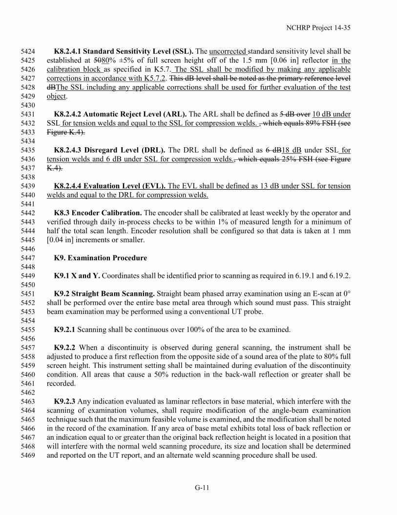
5420 K8.2.4 Amplitude Levels. The following amplitude levels shall be used when evaluating the 5421
test object for detection and rejection of indications (see Table K.2). 5422 5423
NCHRP Project 14-35
G-11
K8.2.4.1 Standard Sensitivity Level (SSL). The uncorrected standard sensitivity level shall be 5424 established at 5080% ±5% of full screen height off of the 1.5 mm [0.06 in] reflector in the 5425 calibration block as specified in K5.7. The SSL shall be modified by making any applicable 5426 corrections in accordance with K5.7.2. This dB level shall be noted as the primary reference level 5427 dBThe SSL including any applicable corrections shall be used for further evaluation of the test 5428 object. 5429
5430 K8.2.4.2 Automatic Reject Level (ARL). The ARL shall be defined as 5 dB over 10 dB under 5431
SSL for tension welds and equal to the SSL for compression welds. , which equals 89% FSH (see 5432 Figure K.4). 5433
5434 K8.2.4.3 Disregard Level (DRL). The DRL shall be defined as 6 dB18 dB under SSL for 5435
tension welds and 6 dB under SSL for compression welds., which equals 25% FSH (see Figure 5436 K.4). 5437
5438 K8.2.4.4 Evaluation Level (EVL). The EVL shall be defined as 13 dB under SSL for tension 5439
welds and equal to the DRL for compression welds. 5440 5441 K8.3 Encoder Calibration. The encoder shall be calibrated at least weekly by the operator and 5442
verified through daily in-process checks to be within 1% of measured length for a minimum of 5443 half the total scan length. Encoder resolution shall be configured so that data is taken at 1 mm 5444 [0.04 in] increments or smaller. 5445
5446 K9. Examination Procedure 5447 5448 K9.1 X and Y. Coordinates shall be identified prior to scanning as required in 6.19.1 and 6.19.2. 5449 5450 K9.2 Straight Beam Scanning. Straight beam phased array examination using an E-scan at 0° 5451
shall be performed over the entire base metal area through which sound must pass. This straight 5452 beam examination may be performed using a conventional UT probe. 5453
5454 K9.2.1 Scanning shall be continuous over 100% of the area to be examined. 5455 5456 K9.2.2 When a discontinuity is observed during general scanning, the instrument shall be 5457
adjusted to produce a first reflection from the opposite side of a sound area of the plate to 80% full 5458 screen height. This instrument setting shall be maintained during evaluation of the discontinuity 5459 condition. All areas that cause a 50% reduction in the back-wall reflection or greater shall be 5460 recorded. 5461
5462 K9.2.3 Any indication evaluated as laminar reflectors in base material, which interfere with the 5463
scanning of examination volumes, shall require modification of the angle-beam examination 5464 technique such that the maximum feasible volume is examined, and the modification shall be noted 5465 in the record of the examination. If any area of base metal exhibits total loss of back reflection or 5466 an indication equal to or greater than the original back reflection height is located in a position that 5467 will interfere with the normal weld scanning procedure, its size and location shall be determined 5468 and reported on the UT report, and an alternate weld scanning procedure shall be used. 5469

NCHRP Project 14-35
G-12
5470 K9.3 Angle-Beam Scanning. Tension and compression welds shall be evaluated differently 5471
using angle-beam scanning.Automatic computer recording of essential ultrasonic data in the 5472 manner of line scans shall be performed down the axial length of each weld. Scanning shall be 5473 performed in accordance with the documented and approved scan plan as detailed in K7. 5474
5475 K9.3.1 Angle-Beam Scanning of Tension Welds. Angle-beam inspection of tension welds 5476
shall be performed using a two-part inspection procedure: (1) encoded line scanning shall be 5477 performed along the longitudinal axis of each weld with automated recording of essential 5478 ultrasonic data and (2) follow-up manual raster scanning shall be performed at all locations where 5479 an indication observed during an encoded line scan exceeded the DRL. Line scanning shall be 5480 performed in accordance with the documented and approved scan plan as detailed in K7. 5481
5482 K9.3.2 Angle-Beam Scanning of Compression Welds. Encoded line scanning shall be 5483
performed along the longitudinal axis of each weld with automated recording of essential 5484 ultrasonic data. Line scanning shall be performed in accordance with the documented and 5485 approved scan plan as detailed in K7. 5486
5487 K9.3.31 Line Scanning Gain. Encoded line Sscanning shall be at SSL for compression welds 5488
and a minimum of 12 dB over SSL for tension welds. may be performed at primary reference level 5489 sensitivity as configured in K8.2.4, provided soft gain or color palette alterations are made during 5490 evaluation to aid in detection. If scanning is performed at primary reference level, soft gain shall 5491 be increased by 6dB or the color palette adjusted to end at 50% screen height during the evaluation 5492 of the weld data. If color palette adjustment or soft gain increase is not used, 6dB of additional 5493 gain over primary reference level shall be applied during scanning. For manual supplemental 5494 examinations such as for transverse flaw detection, scanning shall be a minimum of 6dB over 5495 primary reference level. 5496
5497 K9.3.42 Encoded Line Scanning. Scanning shall be doneperformed with an encoder. Encoded 5498
line scanning shall be performed by using and a mechanical fixture or apparatus which to help 5499 maintains fixed index offset positioning. 5500
5501 K9.3.53 Scanning Speed. The indicated speed of acquisition that is established for the 5502
instrument for the given setup shall not be exceeded. If data dropout is noted, it shall not exceed 5503 1% of the recorded data and no two consecutive lines of data shall be missed. 5504
5505 K9.3.64 Data Collection. The PAUT operator shall ensure that ultrasonic examination data is 5506
recorded in an unprocessed form. A full and complete data recording set of the original A-scan 5507 data with no exclusionary gating or filtering other than receiver bandpass shall be included in the 5508 data record. 5509
5510 K9.3.7 Manual Raster Scanning. Manual raster scanning of tension welds shall be performed 5511
by manual manipulation of the probe when required per K9.3.1. The manual raster scanning shall 5512 be performed using Movement A, B, and C shown in Figure 6.7 in order to sweep all possible 5513 incidence angles over the indication. A screenshot shall be recorded and data documented at the 5514

NCHRP Project 14-35
G-13
location of maximum indication amplitude for all indications exceeding the DRL regardless of 5515 whether they are acceptable or rejectable. 5516
5517 K10. Evaluation 5518 5519 K10.1 Length Measurements. Indication length to mark the limits of repair or for evaluation 5520
against the length limits in Table K.4 shall be determined by using the 6 dB drop method described 5521 in 6.23.2. For saturated indications, in which the true peak amplitude measurement cannot be 5522 obtained, additional scans at lower gain levels shall be performed. For tension welds, the indication 5523 length shall be determined from manual raster scanning. For compression welds, the indication 5524 length shall be determined from the encoded line scan data files. For saturated indications, in which 5525 the true peak amplitude measurement cannot be obtained, additional scans at lower gain levels 5526 shall be performed for Class B and C indications with near rejectable lengths or proximities to 5527 adjacent indications or weld intersections where applicable. The length may be determined from 5528 the stored data file. 5529
5530 K10.2 Acceptance Criteria. Except for additional requirements in K10.2.1 for T and corner 5531
joints loaded perpendicular to the weld, welds shall be acceptable provided they have no cracks, 5532 nor any indications that whose amplitude or amplitude and length exceed that specified in Table 5533 K.42 for the applicable type of loading. Discontinuities shall be classified based on their maximum 5534 amplitude in accordance with Table K.31. Acceptance evaluation is performed on the results of 5535 manual raster scanning for tension welds and encoded line scanning for compression welds. (also 5536 see Figure K.4): 5537
5538 Manual PAUT may be used to supplement the scan in order to determine whether a discontinuity 5539
is a crack. 5540 5541 Indications characterized as cracks shall be considered unacceptable regardless of length or 5542
amplitude. 5543 5544 Class B and C indications shall be separated by at least 2L, L being the length of the longer 5545
indication, except that when two or more such indications are not separated by at least 2L, but the 5546 combined length of indications and their separation distance is equal to or less than the maximum 5547 allowable length under the provisions of Class B or C, the flaw shall be considered a single 5548 acceptable indication. 5549
5550 Class B and C shall not begin at a distance less than 2L from the weld ends carrying primary 5551
tensile stresses, L being the indication length. 5552 5553 For Class C, determination of depth of discontinuity shall be determined by the location of the 5554
peak amplitude, at the angle producing the maximum signal amplitude. 5555 5556 K10.2.1 T and Corner Joints Loaded Perpendicular to the Weld. T and corner joints which 5557
are loaded in tension perpendicular to the weld axis shall be evaluated using the following 5558 acceptance criteria. 5559

NCHRP Project 14-35
G-14
• Indications located within the middle half of the plate thickness shall be evaluated per 5560 K10.2. 5561
• Indications located within the top or bottom quarter of the plate thickness (i.e., near the 5562 surface) shall be rejectable if the amplitude during follow-up raster scanning exceeds the 5563 EVL, regardless of the length. 5564
5565 K10.3 Repair. Repairs to welds found unacceptable by PAUT shall be made in accordance with 5566
3.7. Repaired areas shall be retested using the same scan plan and techniques as used for the 5567 original inspection, unless the scan plan does not provide coverage of the repaired area. In this 5568 case, a new scan plan shall be developed for the repair area. The minimum length of the repair that 5569 shall be reinspected shall be the length of the gouge plus 50 mm [2 in] on each end. 5570
5571 K11. Data Analysis 5572 5573 K11.1 Validation of Coverage. Recorded data shall be assessed to ensure full execution of the 5574
scan plan over 100% of the required examination length. 5575 5576 K11.2 Data Analysis and Recording Requirements. The following are requirements for 5577
evaluation of data: 5578 5579 (1) The entire exam volume shall be analyzed, using gates and available cursors, to locate and 5580
identify the source, location, and nature for all indications exceeding the DRL for both the 5581 longitudinal and transverse scans. Alternately, manual plotting may be used to augment on-board 5582 analysis, e.g., nonparallel or inconsistent geometries. 5583
5584 (2) Responses resulting from surface roughness, weld root, or and weld cap geometries shall be 5585
investigated and the basis for this classification should be noted on the report form. 5586 5587 (3) Any indication warranting evaluation shall be recorded to support the resultant disposition. 5588
The extent of recording shall be sufficient for reviewers and subsequent examiners to repeat the 5589 result and should stand alone as a written record. 5590
5591 (4) Rejectable indicationsWith the exception of indications noted in Item 2, all indications 5592
exceeding the DRL shall be reported as follows: 5593 • For tension welds, indications greater than the DRL but less than the EVL, the report 5594
shall include a screenshot with the peak amplitude obtained from the follow-up raster 5595 scan and the corresponding location in the plate cross-referenced to the encoded line 5596 scan. 5597
• For both tension and compression welds, indications greater than the EVL, the report 5598 shall include peak amplitude, discontinuity classification, length of indication, depth 5599 below the surface, and relative position to provide adequate information when repair is 5600 required. For tension welds the peak amplitude shall be documented with a a screenshot 5601 obtained from the follow-up raster scan and the corresponding location in the plate cross-5602 referenced to the encoded line scan. 5603 5604
NCHRP Project 14-35
G-15
the report shall include peak amplitude, indication rating, length of indication, depth below 5605 the surface, and relative position to provide adequate information for the repair. Cursor 5606 placement, measurement features, and annotations and comments shall clearly support 5607 disposition. 5608
5609 (5) For welds designated in the contract documents as being Fracture Critical, indication ratings 5610
up to and including 6 dB less critical (higher) than acceptance levels shall be recorded on the test 5611 report for informational purposes. 5612
5613 K12. Data Management 5614 5615 K12.1 Data Management System. There shall be a data management scheme established 5616
consistent with job requirements and size. 5617 5618 K12.2 File Nomenclature. A systematic file naming scheme shall be used to control data 5619
management of calibration and set-up files, phased array data files, and digitally generated data 5620 report forms. 5621
5622 K12.3 Raw Data. All phased array data shall be saved in the original raw A-scan format. 5623 5624 K12.4 Data Reviewing. Any review and evaluation of the phased array data shall not change or 5625
affect the original A-scan data. 5626 5627 K13. Documentation and Reporting 5628 5629 K13.1 Reporting. Examination reports shall meet the requirements of 6.20 and may be output 5630
from the on-board reporting feature of the phased array unit provided all necessary information is 5631 included. Reports may also be produced in the written manual UT conventional format or by 5632 external computer-generation. 5633
5634 If PAUT is being substituted for RT, tThe written report shall include, at a minimum, encoded 5635
C-scans covering the entire length inspected and A, C, and sectorial, and side views (see K3.11) 5636 of all reportable indications. All raw data for PAUT substituted for RT shall be retained for the 5637 same duration required for radiographic film. 5638
5639 K13.2 Repairs. Results from PAUT inspections of repaired welds shall be tabulated on the 5640
original form (if available) or additional report forms, and shall be indicated by the appropriate 5641 repair number (R1, R2, R3, etc.) 5642
5643 K13.3 Scan Plan Reporting. The scan plan used during inspection shall accompany the report 5644
form. 5645 5646 K14. System Linearity Verification 5647 5648 K14.1 General Requirements. Linearity verifications shall be conducted at a minimum of 5649
every 12 months and recorded on a form similar to that shown in Table K.64. The verifications 5650

NCHRP Project 14-35
G-16
shall be conducted by a PAUT Level II or III, or at the Contractor’s option, the equipment may be 5651 sent to the manufacturer for verification. 5652
5653 K14.1.1 The phased array instrument shall be configured to display an A-scan presentation. 5654 5655 K14.1.2 The time base of the A-scan shall be adjusted to a suitable range to display the pulse-5656
echo signals selected for the particular linearity verification to be performed. A standard IIW or 5657 other linearity block similar to that described in ASTM E317, Standard Practice for Evaluating 5658 Performance Characteristics of Ultrasonic Pulse-Echo Testing Instruments and Systems without 5659 the Use of Electronic Measurement Instruments, shall be selected to provide signals to assess 5660 linearity aspects of the instrument (see Figure 6.5). 5661
5662 K14.1.3 Pulser parameters shall be selected for the frequency and bandpass filter to optimize 5663
the response from the probe used for the linearity verifications. 5664 5665 K14.1.4 The receiver gain shall be set to display nonsaturating signals of interest for display 5666
height and amplitude control linearity assessments. 5667 5668 K14.2 Display Height Linearity Verification Procedure 5669 5670 (1) With the phased array instrument connected to a probe (shear or longitudinal) and coupled 5671
to any block that will produce two signals, the probe shall be adjusted such that the amplitude of 5672 the two signals are at 80% and 40% of the display screen height. 5673
5674 (2) The gain shall be increased using the receiver gain adjustment to obtain 100% of full screen 5675
height of the larger response. The height of the lower response is recorded at this gain setting as a 5676 percentage of full screen height. 5677
5678 (3) The height of the higher response shall be reduced in 10% steps to 10% of full screen height 5679
and record the height of the second response for each step. 5680 5681 (4) The larger signal shall be returned to 80% to ensure that the smaller signal has not drifted 5682
from its original 40% level due to coupling variation. Repeat the test if variation of the second 5683 signal is greater than 41% or less than 39% full screen height. 5684
5685 (5) For an acceptable tolerance, the responses from the two reflectors shall bear a 2-to-1 5686
relationship to within ±3% of full screen height throughout the range 10% to 100 % (99% if 100% 5687 is saturation) of full screen height. 5688
5689 (6) The results shall be recorded on an instrument linearity form as shown in Table K.64. 5690 5691 K14.3 Amplitude Control Linearity Verification Procedure 5692 5693 Each of the pulser-receiver components shall be checked to determine the linearity of the 5694
instrument amplification capabilities. For instruments configured to read amplitudes greater than 5695
NCHRP Project 14-35
G-17
can be seen on the display, a larger range of checkpoints may be used. For these instruments, the 5696 gated output instead of the A-scan display shall be verified for linearity. 5697
5698 (1) A flat (normal incidence) linear array phased array probe shall be selected having at least as 5699
many elements as the phased array ultrasonic instrument has pulsers. 5700 5701 (2) The phased-array ultrasonic instrument shall be configured using this probe to have an E-5702
scan at 0°. Each focal law will consist of one element. The scan will start at element number 1 and 5703 end at the element number that corresponds to the number of pulsers in the phased-array 5704 instrument. 5705
5706 (3) The probe shall be coupled to a suitable surface to obtain a pulse-echo response from each 5707
focal law. The backwall echo from the 25 mm [1 in] thickness of the IIW block or similar block 5708 provides a suitable target option. Alternatively, immersion testing may be used. 5709
5710 (4) Channel 1 of the pulser-receivers of the phased-array instrument shall be selected. Using the 5711
A-scan display, monitor the response from the selected target. Adjust the gain to bring the signal 5712 to 40% screen height. 5713
5714 (5) The gain shall be added to the receiver in the increments of 1 dB, then 2 dB, then 4 dB, and 5715
then 6 dB. Remove the gain added after each increment to ensure that the signal has returned to 5716 40% display height. Record the actual height of the signal as a percentage of the display height. 5717
5718 (6) The signal shall be adjusted to 100% display height, remove 6 dB gain and record the actual 5719
height of the signal as a percentage of the display height. 5720 5721 (7) Signal amplitudes shall fall within a range of +/- 3% of the display height required in the 5722
allowed height range of Table K.64. 5723 5724 (8) The sequence from (4) to (7) shall be repeated for all other pulser-receiver channels and 5725
record results on a linearity report form as shown in Table K.64. 5726 5727 K14.4 Time-Base Linearity (Horizontal Linearity) Verification Procedure 5728 5729 (1) The phased array instrument shall be configured to display an A-scan presentation using a 5730
250 mm [10 in] range. 5731 5732 (2) Any longitudinal (compression) wave probe shall be selected and the phased-array 5733
instrument shall be configured to display a range obtaining at least ten multiple back reflections 5734 from the 25 mm [1 in] wall thickness of the calibration block. 5735
5736 (3) The phased-array instrument shall be set to an analog-to-digital conversion rate of at least 80 5737
MHz. 5738 5739

NCHRP Project 14-35
G-18
(4) With the probe coupled to the block and the A-scan displaying 10 clearly defined multiples 5740 as illustrated in Figure K.25, the display software shall be used to assess the interval between 5741 adjacent backwall signals. 5742
5743 (5) The acoustic velocity of the test block shall be set by calibration (ASTM E494 may be used 5744
as a guide), the acoustic velocity in the display software shall be entered, and the display shall be 5745 configured to read out in distance (thickness). 5746
5747 (6) Using the reference and measurement cursors, the interval between each multiple shall be 5748
determined and the interval of the first 10 multiples shall be recorded. 5749 5750 (7) Each intermediate trace deflection shall be correct within 2% of the screen width. 5751 5752 K15. Background References 5753 5754 K15.1 ASTM E494, Standard Practice for Measuring Ultrasonic Velocity in Materials 5755 5756 K15.2 ASTM E2491, Standard Guide for Evaluating Performance Characteristics of Phased-5757
Array Ultrasonic Examination Instruments and Systems 5758 5759 K15.3 ASTM E2700, Standard Practice for Contact Ultrasonic Testing of Welds Using Phased 5760
Arrays 5761 5762 K15.4 ISO 2400, Non-destructive testing – Ultrasonic examination specification for calibration 5763
block No. 1 5764 5765 K15.5 NCHRP Project 14-35, Acceptance Criteria of Complete Joint Penetration Steel Bridge 5766
Welds Evaluated Using Enhanced Ultrasonic Methods 5767 5768
NCHRP Project 14-35
G-19
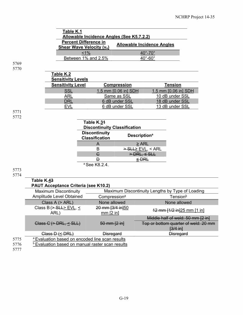
Table K.1 Allowable Incidence Angles (See K5.7.2.2) Percent Difference in
Shear Wave Velocity (vs) Allowable Incidence Angles
<1% 40°-70° Between 1% and 2.5% 40°-60°
5769 5770
Table K.2 Sensitivity Levels Sensitivity Level Compression Tension
SSL 1.5 mm [0.06 in] SDH 1.5 mm [0.06 in] SDH ARL Same as SSL 10 dB under SSL DRL 6 dB under SSL 18 dB under SSL EVL 6 dB under SSL 13 dB under SSL
5771 5772
Table K.31 Discontinuity Classification
Discontinuity Classification Descriptiona
A ≥ ARL B > SLL≥ EVL, < ARL C > DRL, ≤ SLL D ≤ DRL
a See K8.2.4. 5773 5774
Table K.43 PAUT Acceptance Criteria (see K10.2)
Maximum Discontinuity Amplitude Level Obtained
Maximum Discontinuity Lengths by Type of Loading Compressiona Tensionb
Class A (> ARL) None allowed None allowed Class B (> SLL> EVL, <
ARL) 20 mm [3/4 in]50
mm [2 in] 12 mm [1/2 in]25 mm [1 in]
Class C (> DRL, < SLL) 50 mm [2 in] Middle half of weld: 50 mm [2 in]
Top or bottom quarter of weld: 20 mm [3/4 in]
Class D (< DRL) Disregard Disregard a Evaluation based on encoded line scan results 5775 b Evaluation based on manual raster scan results 5776 5777
NCHRP Project 14-35
G-20
Table K.52 Essential Variables for PAUT (see K7.1 and K7.3) Element numbers used for focal laws Angular range of S-scan Calibration block geometry Direction of sound propagation in relation to rolling direction Acoustic property verification Attenuation correction, if required Manufacturer’s documented permitted wedge angular range Weld configurations to be examined, including thickness
dimensions and base material product form (pipe, plate, etc.) Weld type (ESW or non-ESW) Compression or tension scanning method Surface curvature along index axis (e.g., for longitudinal weld
in tubular member) The surfaces from which the examination is performed Techniques (straight beam, angle beam, contact) Search unit types, frequencies, element sizes and shapes Phased array units Manual vs. automated/semi-automated scanning Method for discriminating geometric from weld flawdefect
indications Decrease in scan overlap Method for determining focal/delay laws if other than on-board
equipment algorithms included in the software revision specified Acquisition or analysis software type Probe manufacturer and model Any increase in scanning speed Couplant, if not listed in 6.19.4 Computer enhanced data analysis
5778
NCHRP Project 14-35
G-21
5779 Table K.64 Linearity Verification Report Form (see K14) Location: Date: Operator: Signature: Instrument: Couplant: Pulser Voltage (V): Pulse Duration (ns): Receiver (band): Receiver Smoothing: Digitization Frequency (MHz): Averaging Display Height Linearity Amplitude Control Linearity Large % Small Allowed Range % Small Actual % Ind. Height % dB Allowed Range % 100 47-53 40 +1 42-47 90 42-48 40 +2 48-52 80 40 40 40 +3 60-66 70 32-38 40 +4 77-83 60 27-33 40 +6 47-53 50 22-28 40 17-23 30 12-18 20 7-13 10 2-8 Amplitude Control Linearity Channel Results: (Note any channels that do not fall in the allowed range) Channel (Add more if required for 32 or 64 pulser-receiver units) 1 2 3 4 5 6 7 8 9 10 11 12 13 14 15 16 Time Based (Horizontal) Linearity (for 25 mm [1 in] IIW Blocks) Multiple 1 2 3 4 5 6 7 8 9 10
Thickness 25 mm [1 in]
50 mm [2 in]
75 mm [3 in]
100 mm [4 in]
125 mm [5 in]
150 mm [6 in]
175 mm [7 in]
200 mm [8 in]
225 mm [9 in]
250 mm [10 in]
Measured Interval Allowed deviation (Yes/No)
5780

NCHRP Project 14-35
G-22
5781
Figure K.1―Phased Array Imaging Views (see K3.11)
5782 5783 5784
Figure K.2―Example Standard Reflector Locations in Weld Mockup (see K5.7) Source: Adapted from AWS D1.1/D1.1M:2015, Structural Welding Code—Steel, Figure Q.3, American Welding Society. Graphic
Artist: Figure K2(C): Replace “GROOVE CORNER WELD” with “GROOVE WELD IN
CORNER JOINT” Figure K2(D): Replace “GROOVE T-WELD” with “GROOVE WELD IN T-JOINT”
5785
NCHRP Project 14-35
G-23
Figure K.3―Example Phased Array Calibration Standard (PACS) Type Block (see K5.7.1) SECRETARY NOTE: If any of these units are measurements, we need to have both SI and US Customary shown. I do not know
what these numbers represent, so I will need a subcommittee member to do this. 5786
NCHRP Project 14-35
G-24
ARL (5 dB over SSL)
SSL
DRL (6dB under SSL)
Figure K.4―Sensitivity Levels (see K8.2.4 and K10.2) 5787 5788
Figure K.25―Example of Time Based Linearity Verification (see
K14.4)
NCHRP Project 14-35
G-25
G.2 Annex K Commentary 5789
C-Annex K 5790 5791 Advanced Ultrasonic Examination 5792 5793 C-K2 – Scope. The upper limit on thickness helps ensure that excessively long sound paths, 5794
especially at higher search angles, do not result. Further, Article K5.7.2 provides additional 5795 discussion regarding considerations during calibration associated with sound path. 5796
While these provisions are specifically intended to be used using PAUT, many of the provisions 5797 provide important considerations when using other methods of ultrasonic inspection. 5798
5799 C-K3.4 E-Scan. Also called an electronic scan. 5800 5801 C-K3.11.1 A-Scan. This is the view by which all other views are formed and is the basis for 5802
acceptance or rejection of ultrasonic indications. 5803 5804 C-K3.11.2 C-Scan. Normally the C-scan is uncorrected for angled beam inspections. 5805 5806 C-K3.11.3 Sectorial View. Also called S-scan or sectorial scan. Those terms are not used in this 5807
annex because they are also used to refer to a beam movement pattern (see K3.18). 5808 5809 C-K3.11.4 Side View. Sometimes called B-scan or D-scan. These terms are not used in this 5810
annex because there is no consensus on which letter corresponds to side view or end view. 5811 5812 C-K3.11.5 End View. Sometimes called B-scan or D-scan. These terms are not used in this 5813
annex because there is no consensus on which letter corresponds to side view or end view. 5814 5815 C-K3.12 Line Scan. Also called a linear scan. This term is not used in this annex because “linear 5816
scan” is also used to refer to an E-scan (see K3.4). 5817 5818 Certain types of PAUT operational software allow for the configuration of multiple scan types 5819
(e.g., S-scan + S-scan, or S-scan + E-scan) to be performed in a single line scan. This technology 5820 allows for data collection from multiple search units in a single line scan or from a single search 5821 unit but with multiple scan types generated in sequences. 5822
5823 C-K3.16 Multiple piezoelectric elements are sometimes arranged in patterns in a common 5824
housing; these are usually linear, matrix, or annular in shape. 5825 5826 C-K3.19 S-Scan. Also called a sector scan, sectorial scan, swept angle scan, or azimuthal scan. 5827
See C-K3.11.3 for the use of this term and some of its alternatives to mean a type of imaging view 5828 or data display. 5829
5830 C-K3.20 Saturated Signal. Some systems contain enough bit depth to read signal amplitudes 5831
above 100% FSH, but even then there is an upper voltage limitation that the system can adequately 5832 measure the true amount of voltage returned from the search unit. 5833
5834
NCHRP Project 14-35
G-26
C-K3.25 Time Corrected Gain. Also called time varied gain (TVG). 5835 5836 C-K3.26 Virtual Probe Aperture (VPA). Also called active aperture. 5837 5838 C-K3.27 Volume-Corrected Scan. This correction is found to be useful to compensate for 5839
surface path distance variations in angle-beam inspections. 5840 5841 C-K4.1 Personnel Qualification Requirements. While the specific requirements of the 5842
practical examination are not provided herein (i.e., the number and geometry of test plates, flaw 5843 type, orientation, size, etc.), the owner should verify that the performance testing represents to a 5844 reasonable degree the inspections that will be performed by the technician. For example, if 5845 transition butt welds will be inspected, it would be prudent to ensure the performance testing 5846 includes specimens that include transition butt welds. The number, type, and size of flaws should 5847 represent those which are possible with the given weld process. When developing a test matrix, 5848 the number of flaws should range between 5 and 15 and be distributed within 4 to 8 plates with 5849 consideration given to including blank specimens. Multiple flaw types should also be included 5850 (e.g., cracks, porosity, slag, etc.) The length of the scan should be sufficient to ensure the 5851 technician understands use of the encoder. A minimum length of 18 inches has been found to be 5852 reasonable. Performance testing should also include calibration, in particular as related to Article 5853 K5.7 and reporting tasks. 5854
5855 C-K4.2 Certification Requirements. Recently completed research has shown that the previous 5856
requirements for certification did not ensure operators were capable of reliably detecting and 5857 characterizing critical weld flaws. While formal training and time on the job are very important, 5858 these do not ensure capability and reliability. The objective of the inspection is to identify flaws 5859 and establish if they are rejectable or acceptable. The updated certification requirements are 5860 intended to better identify technicians, through more rigorous performance testing, that have 5861 demonstrated the skills needed to reliably meet this objective. 5862
5863 C-K5.3.1 Phase Array Probe. Optimal probe parameters for butt welds greater than 0.5” 5864
thickness can be achieved by selecting a 2.25 MHz frequency probe with an active aperture of 5865 14x14mm to 20x20mm (16x16mm optimal). For thin plates, smaller apertures for 2.25 MHz 5866 probes may be more appropriate. It is not recommended to use a 2.25 MHz probe with an active 5867 aperture smaller than 8x8mm due to the very short focal distance associated with such a 5868 configuration. 5869
Use of higher frequency probes, such as 5 MHz, may be appropriate, especially for thin 5870 materials. However, the significant difference in material attenuation between the test object and 5871 calibration block must be taken into account for plate thicknesses greater than 0.5”. The 5872 recommended aperture for 5 MHz probes is between 5x5mm – 10x10mm for plates under 0.5” 5873 thickness and 9x9mm -13x13mm for plates greater than 0.5” thickness. 5874
Use of probes with a frequency below 2 MHz is not recommended for most applications using 5875 A709 grades of steel. 5876
5877 C-K5.7 - Calibration for Variation in Acoustic Properties. Historically, it has been assumed 5878
that the acoustic properties (e.g., velocity, attenuation, etc.) of common bridge steels do not vary 5879 significantly. However, recently completed research has shown that this assumption is not always 5880

NCHRP Project 14-35
G-27
valid. For example, attenuation characteristics of the test object can be much different than the 5881 calibration block, in particular when higher frequency probes are used. The velocity of shear 5882 waves in some A709 steels produced using thermo-mechanical control process (TMCP) have been 5883 shown to be considerably different than the shear wave velocity of the calibration block. Further, 5884 some TMCP processed steels have been found to be acoustically anisotropic (i.e., the shear wave 5885 velocity varies between rolling and transverse rolling directions). Special caution and calibration 5886 steps must be taken when scanning acoustic anisotropic materials at an oblique orientation to the 5887 rolling direction. In these instances, the sound beam may split into two beams traveling at different 5888 speeds resulting in significant decreases amplitude and a specific indication showing up as two 5889 unique indications. 5890
5891 C-K5.7.1 Supplemental Calibration Block Geometric and Temperature Requirements. 5892 Calibration blocks are commonly removed from plate material and then rotated to increase the first 5893 leg sound path by directing sound into the edge of the plate (i.e., parallel to the plane of the plate). 5894 This is commonly done in order to minimize the thickness of the plate from which the calibration 5895 block is fabricated. Due to the effects of acoustically anisotropy, the acoustic properties of the 5896 calibration block may be different depending whether the block is scanned through the rolled 5897 surface or through the edge of the original plate. Therefore, the acoustic properties of the 5898 calibration block must be within the requirements of K5.7 for the direction of scanning that will 5899 be used during calibration. 5900
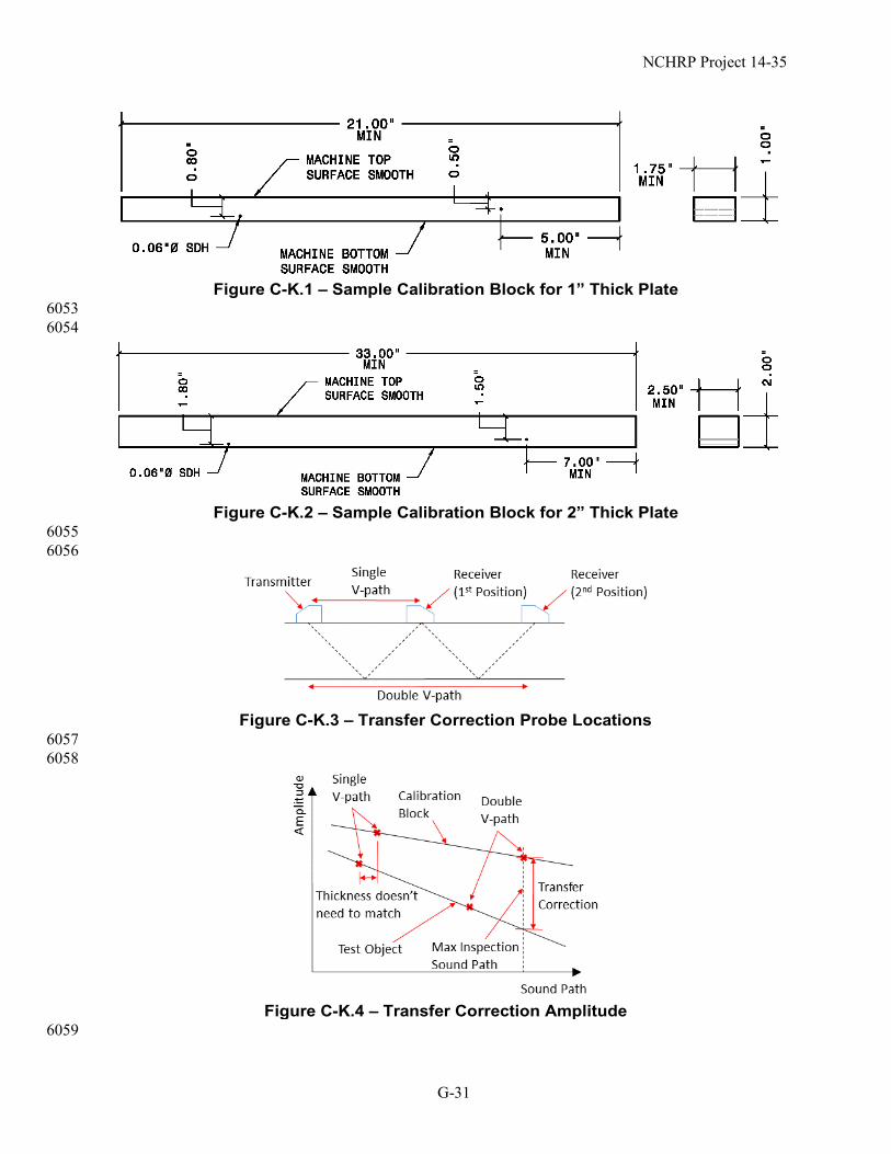
In order to establish TCG throughout the usable sound path range of all configured angles in the 5901 test object, the calibration block must be able to accommodate a TCG point at a sound path at or 5902 beyond the longest sound-path during the inspection. For full V-path examinations from one face 5903 of the joint (i.e., only from Face A as illustrated in Table 6.2), the sound path of the last TCG point 5904 in the calibration block must accommodate the second leg sound path in the test object. There are 5905 two possible methods to accomplish this (1) fabricating a calibration block which is at least 2.25 5906 times the thickness of the test object and performing all of the TCG calibration in the first leg (i.e., 5907 rotating the plate) or (2) fabricating a long calibration block and performing calibration using 5908 multiple backwall reflections (i.e., third leg). It is also recommended that the block be able to 5909 accommodate pitch-catch comparison to the test object. Sample calibration block geometry for 5910 the use of multiple backwall reflections for 1” and 2” thick plate material are shown in Figure C-5911 K.1 and Figure C-K.2, respectively. The dimensions for the plate length, width, side drilled hole 5912 depth, spacing, and placement may all be different depending on the plate thickness and transducer 5913 size and aperture. 5914
5915 C-K5.7.2.1 Attenuation Requirements. Transfer correction using the pitch-catch method 5916
involves two probes with one acting as a transmitter and the other as a receiver. The sound is 5917 skipped off of the backwall of the calibration block and the test object in a single-V and double-V 5918 path, as shown in Figure C-K.3, and the amplitude is measured at each location with the same 5919 transducer settings. These amplitude measurements are then plotted against the sound path and 5920 lines are drawn through the measurements corresponding to the calibration block and the test 5921 object, as shown in Figure C-K.4. The difference in amplitude at the maximum inspection sound 5922 path can be directly obtained from these lines. The thickness of the calibration block and the test 5923 object do not need to match, but the amplitude measurements must be made in the far field in order 5924 to ensure that the change in amplitude is due to attenuation. 5925
5926
NCHRP Project 14-35
G-28
C-K5.7.2.2 Shear Wave Velocity Requirements. Difference between the velocity of shear 5927 waves in the test object and the calibration block can lead to significant errors in measured 5928 amplitude and cause beam divergence, especially at higher search angles (e.g., >60 degrees) 5929 leading to mis-location of the indication. 5930
Measurement of the shear wave velocity in the test object and calibration may be provided either 5931 directly or indirectly. The direct method includes use of a normal incidence shear wave transducer 5932 which emits a polarized shear wave and can be used similar to a normal incidence compression 5933 wave (i.e., straight beam) probe to measure the shear wave velocity in a specific polarized direction 5934 by using successive backwall signals. Shear wave couplant is required in order to propagate shear 5935 waves directly from the transducer to the test piece. Use of this method can directly evaluate 5936 acoustic anisotropic behavior by rotating the polarized shear wave transducer between the rolled 5937 and transverse to rolled directions. 5938
The indirect method for measuring the shear wave velocity involves measuring the actual 5939 incidence angle of a shear wave probe in the test piece and using Snell’s Law, along with the 5940 standard wedge angle and velocity, to calculate the corresponding velocity in the test piece. The 5941 actual incidence angle may be determined through maximizing the amplitude of a reference 5942 reflector or pitch-catch measurement in a single-V path. The incidence angle is then measured 5943 using the horizontal and vertical components of the sound path (i.e., index offset and depth). 5944
5945 C-K7.1 Scan Plans. The same scan plan may be used for similar weld geometries with similar 5946
surrounding component geometries as long as the weld and HAZ are covered. It may be desirable 5947 to develop a library of scan plans that are applicable to common welded joints used in bridges. 5948 For example, a set of accepted scan plans for transition butt welds of plates of various thickness. 5949 However, the user must ensure that all calibration checks noted in Article 5.7.2 have been 5950 performed to account for various in acoustic properties of the base metal and weld metal. 5951
5952 C-K7.1.1 Caution should be applied when using computer modeling programs for creating scan 5953
plan because computation errors are possible, which can lead to inadequate coverage. Due to this, 5954 manual plotting should be used to verify scan plan coverage of the initial configuration when 5955 computer modeling is used. 5956
5957 C-K7.2.1 Index Positions. The number of index positions required will increase as the material 5958
thickness increases. For thinner materials of approximately 6 mm [1/4 in] or less, a single index 5959 may supply the proper coverage if the part configuration allows, but sound coverage must be 5960 provided in two crossing directions. For material thickness above this, 2 or more index positions 5961 are typically required. Ultimately, the adequacy of the number of index positions is determined by 5962 the coverage shown in the scan plan and dictated by the ability to meet the coverage requirements 5963 of K7.4. 5964
5965 C-K7.2.3 Supplemental E-Scans. E-scans may be useful for welds that can be accessed only 5966
from a single side, for welds in T-joints, or other configurations in which complete coverage of 5967 the weld, fusion face, or HAZ will be difficult. 5968
5969 C-K7.4 Testing of Welds. In plates greater than 2” thick, excessive beam spread and amplitude 5970
differences due to attenuation have been observed. In order to mitigate these effects, consideration 5971 should be given to scanning from both faces (i.e., Face A and Face B as illustrated in Table 6.2) in 5972
NCHRP Project 14-35
G-29
order to limit the sound path needed for full coverage in two crossing directions. For welds in 5973 corner or T-joints, the weld may be examined with a straight beam or low-angle longitudinal waves 5974 from an appropriate face to aid in obtaining coverage. 5975
5976 C-K7.4.4 Inspection for Transverse Indications. Encoded scanning is possible but not 5977
practical with scanning pattern D and not compatible with scanning pattern E. Therefore, encoding 5978 is not required for inspection for transverse indications. However, if an encoded line scan is used 5979 the coverage provided by the passive direction of the sound beam should be considered. 5980
5981 C-K8.2.4 Amplitude Levels. The amplitude levels used for evaluation of the test object for 5982
detection and rejection of indications are based on NCHRP Project 14-35. 5983 C-K8.2.4 Standard Sensitivity Level (SSL). SSL, ARL, and DRL are based on AWS D1.1 5984
Annex Q. Annex Q rejection level is 5 dB above SSL. 5 dB is a 1.78:1 ratio. 50% (height of SSL) 5985 × 1.78 = 89% (height of ARL). 5986
5987 C-K9.3.31 Line Scanning Gain. Additional scanning gain when TCG is applied is intended to 5988
aide in detection of relevant indications. for manual examinations. Most phased array equipment 5989 or evaluation software has the capabilities to increase gain (or similar with color palette 5990 adjustments) to serve the same purpose of aiding in detection of discontinuities. Additionally, gain 5991 settings greater than 6dB above SSL would produce saturated signals that would interfere with 5992 relevant signals for acceptance. 5993
5994 C-K9.3.53 Scanning Speed. Exceeding the indicated scanning speed can cause data dropout. 5995 5996 C-K10.2 Acceptance Criteria. The acceptance criteria are based on the research conducted 5997
through NCHRP Project 14-35. These limits are founded in fitness-for-service principles by 5998 correlating the amplitude levels associated with critical flaw sizes in steel bridge welds using 5999 numerical simulations and experimental testing. Characterizing defects as cracks is done by 6000 assessing the location of the indication, signal rise-fall time, pulse duration, echo dynamic patterns, 6001 and amplitude. If cracks are suspected but cannot be confidently characterized, alternate NDT 6002 methods should be used to help classify the indication. There are various resources and training 6003 available for defect characterization. One such resource is the ASME Boiler and Pressure Vessel 6004 Code, Section V, Nonmandatory Appendix P, “Phased Array (PAUT) Interpretation.” Annex Q of 6005 AWS D1.1 has diagrams that are useful to understanding these criteria. 6006
6007 C-K10.2.1 T and Corner Joints Loaded Perpendicular to the Weld. Smaller amplitude limits 6008
are necessary for indications near the surface of T and corner joints loaded perpendicular to the 6009 weld axis due to concentration of stresses in this region. The amount of stress concentration 6010 depends on the geometry of the joint and stiffness of the connecting elements. 6011
6012 C-K11.2 Data Analysis and Recording Requirements. Benign indications such as those 6013
confirmed to be due to geometry and metallurgy need only be noted on the report form. For other 6014 indications, which may be more critical, additional documentation is required for the permanent 6015 record. Previously, additional reporting requirements were in place for welds in Fracture Critical 6016 Members. Since the disregard level used for encoded line scanning and the acceptance criteria for 6017 tension welds are based on fracture mechanics and critical flaw sizes, those additional reporting 6018

NCHRP Project 14-35
G-30
requirements are not necessary. Post-acquisition data analysis will result in numerous evaluative 6019 actions and manipulations intended to characterize indication responses from benign geometries 6020 and metallurgical responses. This process, by its nature, will require modification to ensure 6021 complete and systematic disposition of the examination record. 6022
6023 C-K13.1 Reporting. For particularly long retention requirements, measures may need to be 6024
taken so that the data remains readable (not only that the storage medium is intact but that there is 6025 software to read it). 6026
6027 C-K14.2(1) The probe adjustment may be performed with an angle-beam or 0° technique. The 6028
two signals may be obtained by using a block with multiple side drilled holes located close in 6029 proximity, multiple signals from radius as in a standard IIW/DSC block, or multiple thicknesses 6030 such as the DS block shown in Figure 6.6. The probe is then manipulated to the optimum position 6031 over the reflectors to obtain a 2:1 signal ratio. Once the 2:1 ratio is established, the probe will 6032 remain in that position and gain adjustments are made to set the indications at the specified 6033 amplitude. 6034
6035 (2) The gain shall be increased using the receiver gain adjustment to obtain 100% of full screen 6036
height of the larger response. The height of the lower response is recorded at this gain setting as a 6037 percentage of full screen height. 6038
6039 (3) The height of the higher response shall be reduced in 10% steps to 10% of full screen height 6040
and record the height of the second response for each step. 6041 6042 (4) The larger signal shall be returned to 80% to ensure that the smaller signal has not drifted 6043
from its original 40% level due to coupling variation. Repeat the test if variation of the second 6044 signal is greater than 41% or less than 39% full screen height. 6045
6046 (5) For an acceptable tolerance, the responses from the two reflectors shall bear a 2 to 1 6047
relationship to within ±3% of full screen height throughout the range 10% to 100 % (99% if 100% 6048 is saturation) of full screen height. 6049
6050 (6) The results shall be recorded on an instrument linearity form as shown in Table K4. 6051
6052
NCHRP Project 14-35
G-31
Figure C-K.1 – Sample Calibration Block for 1” Thick Plate
6053 6054
Figure C-K.2 – Sample Calibration Block for 2” Thick Plate
6055 6056
Figure C-K.3 – Transfer Correction Probe Locations
6057 6058
Figure C-K.4 – Transfer Correction Amplitude
6059