Embed Size (px)
DESCRIPTION
AWS welding standard
Citation preview

Specification forFiller Metals forBrazing andBraze Welding
AWS A5.8/A5.8M:2004An American National Standard
Copyright American Welding Society Provided by IHS under license with AWS Licensee=Shell Global Solutions International B.V./5924979112
Not for Resale, 11/15/2006 07:05:48 MSTNo reproduction or networking permitted without license from IHS
--``,,,,,,````,`,`,,,,```,,``,-`-`,,`,,`,`,,`---

550 N.W. LeJeune Road, Miami, Florida 33126
AWS A5.8/A5.8M:2004An American National Standard
Approved byAmerican National Standards Institute
February 11, 2004
Specification for
Filler Metals for Brazing
and Braze Welding
Supersedes ANSI/AWS A5.8-92
Prepared byAWS A5 Committee on Filler Metals and Allied Materials
Under the Direction ofAWS Technical Activities Committee
Approved byAWS Board of Directors
AbstractThis specification prescribes the requirements for the classification of filler metals for brazing and braze welding. The
chemical composition, physical form, and packaging of more than 75 brazing filler metals are specified. The filler metalgroups described include aluminum, cobalt, copper, gold, magnesium, nickel, silver, and brazing filler metals for vacuumservice. Information is provided concerning the liquidus, the solidus, the brazing temperature range, and general areas ofapplication recommended for each filler metal. Additional requirements are included for manufacture, sizes, lengths, andpackaging. A guide is appended to the specification as a source of information concerning the classification systememployed and the intended use of the filler metals for brazing and braze welding.
This specification makes use of both U.S. Customary Units and the International System of Units (SI). Since these arenot equivalent, each must be used independently of the other.
Key Words—Brazing, brazing filler metals, braze welding filler metals, aluminum filler metals, cobalt filler metals, copper filler metals, gold filler metals, magnesium filler metals, nickel filler metals, silver filler metals
Copyright American Welding Society Provided by IHS under license with AWS Licensee=Shell Global Solutions International B.V./5924979112
Not for Resale, 11/15/2006 07:05:48 MSTNo reproduction or networking permitted without license from IHS
--``,,,,,,````,`,`,,,,```,,``,-`-`,,`,,`,`,,`---

Statement on Use of AWS American National StandardsAll standards (codes, specifications, recommended practices, methods, classifications, and guides) of the AmericanWelding Society (AWS) are voluntary consensus standards that have been developed in accordance with the rules of theAmerican National Standards Institute (ANSI). When AWS standards are either incorporated in, or made part of,documents that are included in federal or state laws and regulations, or the regulations of other governmental bodies,their provisions carry the full legal authority of the statute. In such cases, any changes in those AWS standards must beapproved by the governmental body having statutory jurisdiction before they can become a part of those laws andregulations. In all cases, these standards carry the full legal authority of the contract or other document that invokes theAWS standards. Where this contractual relationship exists, changes in or deviations from requirements of an AWSstandard must be by agreement between the contracting parties.
International Standard Book Number: 0-87171-722-0
American Welding Society, 550 N.W. LeJeune Road, Miami, FL 33126
© 2004 by American Welding Society. All rights reservedPrinted in the United States of America
Reprinted: September 2004
AWS American National Standards are developed through a consensus standards development process that bringstogether volunteers representing varied viewpoints and interests to achieve consensus. While AWS administers the processand establishes rules to promote fairness in the development of consensus, it does not independently test, evaluate, orverify the accuracy of any information or the soundness of any judgments contained in its standards.
AWS disclaims liability for any injury to persons or to property, or other damages of any nature whatsoever, whether spe-cial, indirect, consequential or compensatory, directly or indirectly resulting from the publication, use of, or reliance on thisstandard. AWS also makes no guaranty or warranty as to the accuracy or completeness of any information published herein.
In issuing and making this standard available, AWS is not undertaking to render professional or other services for or onbehalf of any person or entity. Nor is AWS undertaking to perform any duty owed by any person or entity to someoneelse. Anyone using these documents should rely on his or her own independent judgment or, as appropriate, seek the adviceof a competent professional in determining the exercise of reasonable care in any given circumstances.
This standard may be superseded by the issuance of new editions. Users should ensure that they have the latest edition.
Publication of this standard does not authorize infringement of any patent. AWS disclaims liability for the infringementof any patent resulting from the use or reliance on this standard.
Finally, AWS does not monitor, police, or enforce compliance with this standard, nor does it have the power to do so.
On occasion, text, tables, or figures are printed incorrectly, constituting errata. Such errata, when discovered, are postedon the AWS web page (www.aws.org).
Official interpretations of any of the technical requirements of this standard may only be obtained by sending a request, in writ-ing, to the Managing Director, Technical Services Division, American Welding Society, 550 N.W. LeJeune Road, Miami, FL33126 (see Annex A). With regard to technical inquiries made concerning AWS standards, oral opinions on AWS standardsmay be rendered. However, such opinions represent only the personal opinions of the particular individuals giving them. Theseindividuals do not speak on behalf of AWS, nor do these oral opinions constitute official or unofficial opinions or interpreta-tions of AWS. In addition, oral opinions are informal and should not be used as a substitute for an official interpretation.
This standard is subject to revision at any time by the AWS A5 Committee on Filler Metals and Allied Materials. It mustbe reviewed every five years, and if not revised, it must be either reaffirmed or withdrawn. Comments (recommenda-tions, additions, or deletions) and any pertinent data that may be of use in improving this standard are required andshould be addressed to AWS Headquarters. Such comments will receive careful consideration by the AWS A5 Committeeon Filler Metals and Allied Materials and the author of the comments will be informed of the Committee’s response tothe comments. Guests are invited to attend all meetings of the AWS A5 Committee on Filler Metals and Allied Materialsto express their comments verbally. Procedures for appeal of an adverse decision concerning all such comments are pro-vided in the Rules of Operation of the Technical Activities Committee. A copy of these Rules can be obtained from theAmerican Welding Society, 550 N.W. LeJeune Road, Miami, FL 33126.
Photocopy Rights
Authorization to photocopy items for internal, personal, or educational classroom use only, or the internal, personal, oreducational classroom use only of specific clients, is granted by the American Welding Society (AWS) provided that theappropriate fee is paid to the Copyright Clearance Center, 222 Rosewood Drive, Danvers, MA 01923, Tel: 978-750-8400;online: http://www.copyright.com.
Copyright American Welding Society Provided by IHS under license with AWS Licensee=Shell Global Solutions International B.V./5924979112
Not for Resale, 11/15/2006 07:05:48 MSTNo reproduction or networking permitted without license from IHS
--``,,,,,,````,`,`,,,,```,,``,-`-`,,`,,`,`,,`---

iii
Personnel
AWS A5 Committee on Filler Metals and Allied Materials
D. A. Fink, Chair The Lincoln Electric CompanyJ. S. Lee, 1st Vice Chair Chicago Bridge & Iron Company
H. D. Wehr, 2nd Vice Chair Arcos AlloysR. Gupta, Secretary American Welding Society
*R. L. Bateman Electromanufacturas, S.A.J. M. Blackburn Naval Surface Warfare Center
*B. S. Blum ConsultantR. S. Brown Carpenter Technology Corporation
*J. Caprarola ConsultantA. Chatterjee Caterpillar, Incorporated
R. J. Christoffel ConsultantG. Crisi Universidade Presbiteriana Mackenzie
D. D. Crockett The Lincoln Electric Company*R. A. Daemen Consultant
J. DeVito ESAB Welding and Cutting ProductsD. A. DelSignore Consultant
H. W. Ebert ConsultantJ. G. Feldstein Foster Wheeler Energy Corporation
S. E. Ferree ESAB Welding and CuttingR. D. Fuchs Bohler Thyssen Welding USA, Incorporated
C. E. Fuerstenau Lucas-Milhaupt, IncorporatedD. Haynie Kobelco Welding
J. A. Henning Deltak, Incorporated*J. P. Hunt Consultant
M. Q. Johnson Edison Welding InstituteR. B. Kadiyala Techalloy Company
S. D. Kiser Special MetalsP. J. Konkol Concurrent Technologies
D. J. Kotecki The Lincoln Electric CompanyD. Y. Ku American Bureau of Shipping
R. A. LaFave Elliott Turbomachinery CompanyA. S. Laurenson Consultant
G. H. MacShane MAC AssociatesW. A. Marttila Daimler Chrysler Corporation
R. Menon Stoody CompanyM. T. Merlo Select-Arc, IncorporatedA. R. Mertes Ampco Metal, IncorporatedM. D. Morin ABB Alstom Power
C. L. Null NAVSEAM. P. Parekh Hobart Brothers CompanyR. L. Peaslee Wall Colmonoy Corporation
M. A. Quintana The Lincoln Electric Company*S. D. Reynolds, Jr. Consultant
L. F. Roberts CWB Group
*Advisor
Copyright American Welding Society Provided by IHS under license with AWS Licensee=Shell Global Solutions International B.V./5924979112
Not for Resale, 11/15/2006 07:05:48 MSTNo reproduction or networking permitted without license from IHS
--``,,,,,,````,`,`,,,,```,,``,-`-`,,`,,`,`,,`---

iv
AWS A5 Committee on Filler Metals and Allied Materials (Continued)
P. K. Salvesen Det Norske Veritas (DNV)A. P. Seidler Armco Steel
W. S. Severance ESAB Welding and CuttingE. R. Stevens Consultant
R. A. Swain Euroweld, Limited*E. S. Surian Air Liquide Argentina, S.A.
R. D. Thomas, Jr. R. D. Thomas & CompanyK. P. Thornberry J. W. Harris Company, Incorporated
*S. Tsutsumi Kobe Steel, Ltd.L. T. Vernam AlcoTec Wire Corporation
G. J. Vytanovych ConsultantT. R. Warren Ingalls Shipbuilding, Incorporated*F. J. Winsor Consultant
AWS A5H Subcommittee on Filler Metals and Fluxes for Brazing and Braze Welding
C. E. Fuerstenau, Chair Lucas-Milhaupt, IncorporatedC. L. Jenney, Secretary American Welding Society
*G. A. Andreano Gana & Associates, IncorporatedY. Baskin The Superior Flux and Manufacturing Company
*R. E. Cook ConsultantT. P. Hirthe Kru-Mar Manufacturing Services, Incorporated
T. A. Kern ConsultantM. J. Lucas, Jr. G. E. Aircraft Engines
*J. A. Miller ConsultantR. L. Peaslee Wall Colmonoy Corporation
C. W. Philp Consultant*C. B. Pollock American Welding Society*W. D. Rupert Wolverine Joining TechnologiesJ. L. Schuster Omni Technologies Corporation
A. Severin Bradley CorporationJ. J. Stephens Sandia National Laboratories
*R. D. Thomas, Jr. R. D. Thomas and CompanyK. P. Thornberry J. W. Harris Company, Incorporated
*Advisor
Copyright American Welding Society Provided by IHS under license with AWS Licensee=Shell Global Solutions International B.V./5924979112
Not for Resale, 11/15/2006 07:05:48 MSTNo reproduction or networking permitted without license from IHS
--``,,,,,,````,`,`,,,,```,,``,-`-`,,`,,`,`,,`---

v
Foreword
(This Foreword is not a part of AWS A5.8/A5.8M:2004, Specification for Filler Metals forBrazing and Braze Welding, but is included for informational purposes only.)
This document is the first of the AWS A5.8 specification revisions that makes use of both the U.S. Customary Unitsand the International System of Units (SI). The measurements are not exact equivalents; therefore, each system mustbe used independently of the other without combining values in any way. In selecting rational metric units, AWS A1.1,Metric Practice Guide for the Welding Industry, and International Standard ISO 544, Welding Consumables—TechnicalDelivery Conditions for Welding Filler Materials—Type of Product, Dimensions, Tolerances, and Markings, are usedwhere suitable. Tables and figures make use of both U.S. Customary Units and SI units, which with the application of thespecified tolerances provides for interchangeability of products in both U.S. Customary Units and SI units.
The current document is the ninth revision of the initial joint filler metal specification for brazing issued by theAmerican Welding Society (AWS). The original specification was prepared by a joint committee of the AmericanWelding Society and the American Society for Testing and Materials (ASTM). This joint activity continued for 17 yearsuntil 1969, when AWS became solely responsible for the development and publishing of the specification
The evolution of AWS A5.8/A5.8M, Specification for Filler Metals for Brazing and Braze Welding, is shown below:
ASTM B260-52T, AWS A5.8-52T Tentative Specification for Brazing Filler MetalASTM B260-56T, AWS A5.8-56T Tentative Specification for Brazing Filler MetalAWS A5.8-62T, ASTM B260-62T Tentative Specification for Brazing Filler MetalAWS A5.8-69 Specification for Brazing Filler MetalANSI/AWS A5.8-76 Specification for Brazing Filler MetalANSI/AWS A5.8-81 Specification for Brazing Filler MetalANSI/AWS A5.8-89 Specification for Filler Metals for BrazingANSI/AWS A5.8-92 Specification for Filler Metals for Brazing and Braze Welding
The present edition, which supercedes ANSI/AWS A5.8-92, includes new filler metals. These are AWS BCu-1b;AWS BCu-3; AWS BCuP-8; AWS BCuP-9; AWS BNi-5b; AWS BNi-12; AWS BNi-13; AWS BVAu-3, Grades 1 and2; BVAu-9, Grades 1 and 2; and BVAu-10, Grades 1 and 2.
Comments and suggestions for the improvement of this standard are welcome. They should be sent to the Secretary,AWS A5 Committee on Filler Metals and Allied Materials, American Welding Society, 550 N.W. LeJeune Road, Miami,FL 33126.
Official interpretations of any of the technical requirements of this standard may only be obtained by sending arequest, in writing, to the Managing Director, Technical Services Division, American Welding Society. A formal replywill be issued after it has been reviewed by the appropriate personnel, following established procedures (see Annex C).
Errata(The following Errata have been identified and incorporated into the current reprint of this document.)
Page 6, in Table 4, Titled “Chemical Composition Requirements for Copper, Copper-Zinc, and Copper-PhosphorousFiller Metals,” change the UNS number for BCuP-9 to C55385.
Copyright American Welding Society Provided by IHS under license with AWS Licensee=Shell Global Solutions International B.V./5924979112
Not for Resale, 11/15/2006 07:05:48 MSTNo reproduction or networking permitted without license from IHS
--``,,,,,,````,`,`,,,,```,,``,-`-`,,`,,`,`,,`---

This page is intentionally blank.
Copyright American Welding Society Provided by IHS under license with AWS Licensee=Shell Global Solutions International B.V./5924979112
Not for Resale, 11/15/2006 07:05:48 MSTNo reproduction or networking permitted without license from IHS
--``,,,,,,````,`,`,,,,```,,``,-`-`,,`,,`,`,,`---

vii
Table of Contents
Page No.
Personnel .................................................................................................................................................................... iiiForeword ......................................................................................................................................................................vList of Tables ............................................................................................................................................................ viiiList of Figures........................................................................................................................................................... viii
1. Scope .....................................................................................................................................................................1
Part A—General Requirements ....................................................................................................................................1
2. Normative References ...........................................................................................................................................1
3. Classification.........................................................................................................................................................2
4. Acceptance ............................................................................................................................................................2
5. Certification...........................................................................................................................................................2
6. Rounding-Off Procedure .......................................................................................................................................2
Part B—Tests, Procedures, and Requirements ............................................................................................................2
7. Summary of Tests..................................................................................................................................................2
8. Retest .....................................................................................................................................................................2
9. Chemical Analysis.................................................................................................................................................4
10. Sieve Analysis .......................................................................................................................................................4
11. Melt Cleanliness Test ............................................................................................................................................4
12. Spatter Test............................................................................................................................................................9
13. Binder Content of Transfer Tape ..........................................................................................................................9
Part C—Manufacture, Identification, and Packaging ...............................................................................................10
14. Method of Manufacture.......................................................................................................................................10
15. Standard Forms, Sizes, and Tolerances...............................................................................................................10
16. Filler Metal Identification ...................................................................................................................................10
17. Packaging ............................................................................................................................................................10
18. Marking of Packages...........................................................................................................................................10
Nonmandatory Annexes..............................................................................................................................................15Annex A—Guide to AWS A5.8/A5.8M:2004, Specification for Filler Metals for Brazing and Braze Welding .........15Annex B—Analytical Methods ....................................................................................................................................29Annex C—Guidelines for Preparation of Technical Inquiries for American Welding Society (AWS)Annex C—Technical Committees ...............................................................................................................................31
AWS Filler Metal Specifications by Material and Welding Process..........................................................................33
AWS Filler Metal Specifications and Related Documents .........................................................................................35
List of AWS Documents on Brazing and Soldering ....................................................................................................37
Copyright American Welding Society Provided by IHS under license with AWS Licensee=Shell Global Solutions International B.V./5924979112
Not for Resale, 11/15/2006 07:05:48 MSTNo reproduction or networking permitted without license from IHS
--``,,,,,,````,`,`,,,,```,,``,-`-`,,`,,`,`,,`---

viii
List of Tables
Table Page No.
1 Chemical Composition Requirements for Silver Filler Metals......................................................................32 Chemical Composition Requirements for Gold Filler Metals .......................................................................43 Chemical Composition Requirements for Aluminum and Magnesium Filler Metals ...................................54 Chemical Composition Requirements for Copper, Copper-Zinc, and Copper-Phosphorus
Filler Metals ...................................................................................................................................................65 Chemical Composition Requirements for Nickel and Cobalt Filler Metals ..................................................76 Chemical Composition Requirements for Filler Metals for Vacuum Service ...............................................87 Powder Mesh Designations and Particle Size Distribution ...........................................................................98 Standard Forms and Sizes of Filler Metals ....................................................................................................19 Tolerances for Wrought Wire and Rod........................................................................................................14
10 Tolerances for Foil Strip and Sheet..............................................................................................................14A1 Solidus, Liquidus, and Brazing Temperature Ranges..................................................................................18A2 Discontinued Brazing Filler Metal Classifications ......................................................................................26
List of Figures
Figure Page No.
A1 Precautionary Information for Brazing Processes and Equipment ..............................................................28A2 Precautionary Information for Brazing Filler Metals Containing Cadmium...............................................28
Copyright American Welding Society Provided by IHS under license with AWS Licensee=Shell Global Solutions International B.V./5924979112
Not for Resale, 11/15/2006 07:05:48 MSTNo reproduction or networking permitted without license from IHS
--``,,,,,,````,`,`,,,,```,,``,-`-`,,`,,`,`,,`---

AWS A5.8/A5.8M:2004
1
1. Scope1.1 This specification prescribes requirements for theclassification of filler metals for brazing and braze weld-ing. It includes filler metals for brazing with or without aflux and in all protective atmospheres for various applica-tions, including those for vacuum service.1 The prefix“RB” indicates that the filler metal is suitable for use bothas brazing rod for braze welding and as a brazing fillermetal.
1.2 Safety and health issues and concerns are beyond thescope of this standard and, therefore, are not fully ad-dressed herein. Some safety and health information canbe found in the nonmandatory annex sections A5 andA10. Safety and health information is available fromother sources, including, but not limited to, ANSI Z49.1,Safety in Welding, Cutting, and Allied Processes, andapplicable federal and state regulations.
1.3 This specification makes use of both U.S. CustomaryUnits and the International System of Units (SI). Themeasurements are not exact equivalents; therefore, eachsystem must be used independently of the other withoutcombining in any way when referring to material proper-ties. The specification with the designation A5.8 uses U.S.Customary Units. The specification A5.8M uses SI Units.The latter are shown within brackets [ ] or in appropriatecolumns in tables and figures. Standard dimensions basedon either system may be used for sizing of filler metal orpackaging or both under A5.8 or A5.8M specifications.
Part AGeneral Requirements
2. Normative References2.1 The following standards contain provisions which,through reference in this text, constitute provisions of
1. Filler metals for vacuum service are for devices operating invacuum service, regardless of the atmosphere used in makingthe joint.
this AWS standard. For dated references, subsequentamendments to, or revisions of, any of these publicationsdo not apply. However, parties to agreements based onthis AWS standard are encouraged to investigate the pos-sibility of applying the most recent editions of the docu-ments shown below. For undated references, the latestedition of the standard referred to applies.
2.2 The following AWS standards2 are referenced in themandatory sections of this document:
(1) AWS A5.01, Filler Metal Procurement Guidelines.
2.3 The following ANSI standards3 are referenced in themandatory sections of this document:
(1) ANSI Z49.1, Safety in Welding, Cutting, andAllied Processes.
2.4 The following ASTM standards4 are referenced inthe mandatory sections of this document:
(1) Analytical Chemistry for Metals, Ores, and Re-lated Materials (I): C 571–E 354, Annual Book of ASTMStandards, Analytical Chemistry of Metals, Ores, andRelated Materials;
(2) Analytical Chemistry for Metals, Ores, and Re-lated Materials (II): E 356 to last; Molecular Spectros-copy; Surface Analysis, Annual Book of ASTMStandards, Analytical Chemistry of Metals, Ores, andRelated Materials;
2. AWS standards can be obtained from Global EngineeringDocuments, an Information Handling Services Group com-pany, 15 Inverness Way East, Englewood, Colorado 80112-5776; telephones: (800) 854-7179, (303) 397-7956; fax (303)397-2740; Internet: www.global.ihs.com.3. ANSI standards can be obtained from American NationalStandards Institute, 25 West 43 Street, Fourth Floor, NewYork, New York 10036 and Global Engineering Documents, anInformation Handling Services Group company, 15 InvernessWay East, Englewood, Colorado 80112-5776; telephones:(800) 854-7179, (303) 397-7956; fax (303) 397-2740; Internet:www.global.ihs.com.4. ASTM standards can be obtained from the American Societyfor Testing and Materials, 100 Barr Harbor Drive, West Con-shohocken, PA 19428-2959.
Specification for Filler Metals for Brazing and Braze Welding
Copyright American Welding Society Provided by IHS under license with AWS Licensee=Shell Global Solutions International B.V./5924979112
Not for Resale, 11/15/2006 07:05:48 MSTNo reproduction or networking permitted without license from IHS
--``,,,,,,````,`,`,,,,```,,``,-`-`,,`,,`,`,,`---

AWS A5.8/A5.8M:2004
2
(3) ASTM B 214, Standard Method for Sieve Analy-sis of Granular Metal Powders;
(4) ASTM DS-56, Metals and Alloys in the UnifiedNumbering System;
(5) ASTM E 11-01, Standard Specification for WireCloth and Sieves for Testing Purposes; and
(6) ASTM E 29, Standard Practice for Using Signifi-cant Digits in Test Data to Determine Conformance withSpecifications.
3. Classification 5
3.1 The brazing filler metals covered by the A5.8/A5.8Mspecification are classified using a system that is inde-pendent of U.S. Customary Units and the InternationalSystem of Units (SI). Classification is according to thechemical composition of the brazing filler metal as spec-ified in Tables 1 through 6.
3.2 Filler metal classified under one classification shallnot be classified under any other classification of thisspecification.
4. Acceptance 6
Acceptance of the brazing filler metal shall be in ac-cordance with the provisions of AWS A5.01, FillerMetal Procurement Guidelines.
5. Certification 7
By affixing the AWS specification and classificationdesignations to the packaging, or the classification to theproduct, the manufacturer certifies that the product meetsthe requirements of this specification.
6. Rounding-Off ProcedureFor the purpose of determining conformance with this
specification, an observed or calculated value shall berounded to the “nearest unit” in the last right-hand placeof figures used in expressing the limiting value in accor-dance with the rounding-off method given in ASTM E 29,
5. An explanation of the method of classification of the fillermetals is included in A2.6. See A3, “Acceptance,” for further information concerningacceptance and the testing of the material shipped, as well asAWS A5.01, Filler Metal Procurement Guidelines.7. See A4, “Certification,” for further information concerningcertification and the testing called for to meet this requirement.
Standard Practice for Using Significant Digits in TestData to Determine Conformance with Specifications.
Part BTests, Procedures, and Requirements
7. Summary of Tests
The tests required for each classification or productform are as follows:
7.1 Chemical analysis of the filler metal is required forall classifications.
7.2 Filler metals for vacuum service require a meltcleanliness test and a spatter test in addition to chemicalanalysis.
7.3 Sieve analysis is required for all powdered brazingfiller metal.
7.4 A binder content test for transfer tape used in con-junction with powdered brazing filler metals is required.
The material for the preparation of test samples, thebrazing and testing procedures to be employed, and theresults required are specified in Sections 9 through 13.
8. Retest
If the results of any test fail to meet the requirement,that test shall be repeated twice. The results of both re-tests shall meet the requirement. Samples for retest maybe taken from the original sample or from one or twonew samples. For chemical analysis, retest need be onlyfor the specific elements that failed to meet the require-ment. If the results of one or both retests fail to meet therequirement, the material under test shall be consideredas not meeting the requirements of this specification forthat classification.
In the event that during the preparation or after thecompletion of any test it is clearly determined that pre-scribed or proper procedures were not followed in pre-paring the test sample(s) or in conducting the test, thetest shall be considered invalid without regard to whetherthe test was actually completed or whether test resultsmet or failed to meet the requirement. That test shall berepeated following proper prescribed procedures. In thiscase, the requirement for doubling the number of testspecimens does not apply.
5
6
7
Copyright American Welding Society Provided by IHS under license with AWS Licensee=Shell Global Solutions International B.V./5924979112
Not for Resale, 11/15/2006 07:05:48 MSTNo reproduction or networking permitted without license from IHS
--``,,,,,,````,`,`,,,,```,,``,-`-`,,`,,`,`,,`---

AW
S A
5.8/A5.8M
:2004
3
Table 1a, b
Chemical Composition Requirements for Silver Filler Metals
AWS Classification
UNSNumberc
Composition, Weight Percent
Ag Cu Zn Cd Ni Sn Li Mn
OtherElements,
Totald
BAg-1 P07450 44.0–46.0 14.0–16.0 14.0–18.0 23.0–25.0 — — — — 0.15BAg-1a P07500 49.0–51.0 14.5–16.5 14.5–18.5 17.0–19.0 — — — — 0.15BAg-2 P07350 34.0–36.0 25.0–27.0 19.0–23.0 17.0–19.0 — — — — 0.15BAg-2a P07300 29.0–31.0 26.0–28.0 21.0–25.0 19.0–21.0 — — — — 0.15BAg-3 P07501 49.0–51.0 14.5–16.5 13.5–17.5 15.0–17.0 2.5–3.5 — — — 0.15BAg-4 P07400 39.0–41.0 29.0–31.0 26.0–30.0 — 1.5–2.5 — — — 0.15BAg-5 P07453 44.0–46.0 29.0–31.0 23.0–27.0 — — — — — 0.15BAg-6 P07503 49.0–51.0 33.0–35.0 14.0–18.0 — — — — — 0.15BAg-7 P07563 55.0–57.0 21.0–23.0 15.0–19.0 — — 4.5–5.5 — — 0.15BAg-8 P07720 71.0–73.0 Remainder — — — — — — 0.15BAg-8a P07723 71.0–73.0 Remainder — — — — 0.25–0.50 — 0.15BAg-9 P07650 64.0–66.0 19.0–21.0 13.0–17.0 — — — — — 0.15BAg-10 P07700 69.0–71.0 19.0–21.0 8.0–12.0 — — — — — 0.15BAg-13 P07540 53.0–55.0 Remainder 4.0–6.0 — 0.5–1.5 — — — 0.15BAg-13a P07560 55.0–57.0 Remainder — — 1.5–2.5 — — — 0.15BAg-18 P07600 59.0–61.0 Remainder — — — 9.5–10.5 — — 0.15BAg-19 P07925 92.0–93.0 Remainder — — — — 0.15–0.30 — 0.15BAg-20 P07301 29.0–31.0 37.0–39.0 30.0–34.0 — — — — — 0.15BAg-21 P07630 62.0–64.0 27.5–29.5 — — 2.0–3.0 5.0–7.0 — — 0.15BAg-22 P07490 48.0–50.0 15.0–17.0 21.0–25.0 — 4.0–5.0 — — 7.0–8.0 0.15BAg-23 P07850 84.0–86.0 — — — — — — Remainder 0.15BAg-24 P07505 49.0–51.0 19.0–21.0 26.0–30.0 — 1.5–2.5 — — — 0.15BAg-26 P07250 24.0–26.0 37.0–39.0 31.0–35.0 — 1.5–2.5 — — 1.5–2.5 0.15BAg-27 P07251 24.0–26.0 34.0–36.0 24.5–28.5 12.5–14.5 — — — — 0.15BAg-28 P07401 39.0–41.0 29.0–31.0 26.0–30.0 — — 1.5–2.5 — — 0.15BAg-33 P07252 24.0–26.0 29.0–31.0 25.5–29.5 16.5–18.5 — — — — 0.15BAg-34 P07380 37.0–39.0 31.0–33.0 26.0–30.0 — — 1.5–2.5 — — 0.15BAg-35 P07351 34.0–36.0 31.0–33.0 31.0–35.0 — — — — — 0.15BAg-36 P07454 44.0–46.0 26.0–28.0 23.0–27.0 — — 2.5–3.5 — — 0.15BAg-37 P07253 24.0–26.0 39.0–41.0 31.0–35.0 — — 1.5–2.5 — — 0.15Notes:a. See Table A2 for discontinued brazing filler metal classifications.b. See Table 6 for the following Ag classification not included here: BVAg-0, BVAg-6b, BVAg-8b, and BVAg-29 to BVAg-32.c. ASTM DS-56, Metals and Alloys in the Unified Numbering System.d. The brazing filler metal shall be analyzed for those specific elements for which values are shown in this table. If the presence of other elements is indicated in the course of this work, the amount of those
elements shall be determined to ensure that their total does not exceed the limit specified.
Copyright A
merican W
elding Society
Provided by IH
S under license w
ith AW
S
Licensee=S
hell Global S
olutions International B.V
./5924979112 N
ot for Resale, 11/15/2006 07:05:48 M
ST
No reproduction or netw
orking permitted w
ithout license from IH
S
--``,,,,,,````,`,`,,,,```,,``,-`-`,,`,,`,`,,`---
AWS A5.8/A5.8M:2004
4
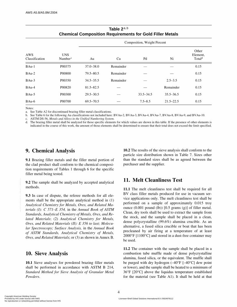
9. Chemical Analysis
9.1 Brazing filler metals and the filler metal portion ofthe clad product shall conform to the chemical composi-tion requirements of Tables 1 through 6 for the specificfiller metal being tested.
9.2 The sample shall be analyzed by accepted analyticalmethods.
9.3 In case of dispute, the referee methods for all ele-ments shall be the appropriate analytical method in (1)Analytical Chemistry for Metals, Ores, and Related Ma-terials (I): C 571–E 354, in the Annual Book of ASTMStandards, Analytical Chemistry of Metals, Ores, and Re-lated Materials; (2) Analytical Chemistry for Metals,Ores, and Related Materials (II): E 356 to last; Molecu-lar Spectroscopy; Surface Analysis, in the Annual Bookof ASTM Standards, Analytical Chemistry of Metals,Ores, and Related Materials; or (3) as shown in Annex B.
10. Sieve Analysis
10.1 Sieve analyses for powdered brazing filler metalsshall be performed in accordance with ASTM B 214,Standard Method for Sieve Analysis of Granular MetalPowders.
10.2 The results of the sieve analysis shall conform to theparticle size distribution shown in Table 7. Sizes otherthan the standard sizes shall be as agreed between thepurchaser and the supplier.
11. Melt Cleanliness Test
11.1 The melt cleanliness test shall be required for allBV class filler metals produced for use in vacuum ser-vice applications only. The melt cleanliness test shall beperformed on a sample of approximately 0.015 troyounce (0.001 pound (lb)) [0.5 grams (g)] of filler metal.Clean, dry tools shall be used to extract the sample fromthe stock, and the sample shall be placed in a clean,dense polycrystalline (99.6%) alumina crucible. As analternative, a fused silica crucible or boat that has beenprecleaned by air firing at a temperature of at least2000°F [1100°C] and stored in a dust-free container maybe used.
11.2 The container with the sample shall be placed in acombustion tube muffle made of dense polycrystallinealumina, fused silica, or the equivalent. The muffle shallbe purged with dry hydrogen (–40°F [–40°C] dew pointor lower), and the sample shall be heated to a minimum of36°F [20°C] above the liquidus temperature establishedfor the material (see Table A1). It shall be held at that
Table 2a, b
Chemical Composition Requirements for Gold Filler Metals
AWS Classification
UNSNumberc
Composition, Weight Percent
Au Cu Pd Ni
OtherElement,
Totald
BAu-1 P00375 37.0–38.0 Remainder — — 0.15
BAu-2 P00800 79.5–80.5 Remainder — — 0.15
BAu-3 P00350 34.5–35.5 Remainder — 2.5–3.5 0.15
BAu-4 P00820 81.5–82.5 — — Remainder 0.15
BAu-5 P00300 29.5–30.5 — 33.5–34.5 35.5–36.5 0.15
BAu-6 P00700 69.5–70.5 — 7.5–8.5 21.5–22.5 0.15
Notes:a. See Table A2 for discontinued brazing filler metal classifications.b. See Table 6 for the following Au classifications not included here: BVAu-2, BVAu-3, BVAu-4, BVAu-7, BVAu-8, BVAu-9, and BVAu-10.c. ASTM DS-56, Metals and Alloys in the Unified Numbering System.d. The brazing filler metal shall be analyzed for those specific elements for which values are shown in this table. If the presence of other elements is
indicated in the course of this work, the amount of those elements shall be determined to ensure that their total does not exceed the limit specified.
Copyright American Welding Society Provided by IHS under license with AWS Licensee=Shell Global Solutions International B.V./5924979112
Not for Resale, 11/15/2006 07:05:48 MSTNo reproduction or networking permitted without license from IHS
--``,,,,,,````,`,`,,,,```,,``,-`-`,,`,,`,`,,`---

AW
S A
5.8/A5.8M
:2004
5
Table 3a
Chemical Composition Requirements for Aluminum and Magnesium Filler Metals
AWS Classification
UNS Numberc
Chemical Composition, Weight Percentb
Si Cu Mg Bi Fe Zn Mn Cr Ni Ti Be Al
Other Elementsd
Each Total
BAlSi-2BAlSi-3BAlSi-4BAlSi-5BAlSi-7BAlSi-9BAlSi-11BMg-1
A94343A94145A94047A94045A94004A94147A94104Ml900l
6.8–8.29.3–10.711.0–13.0
9.0–11.09.0–10.5
11.0–13.09.0–10.5
0.05
0.253.3–4.7
0.300.300.250.250.250.05
—0.150.100.05
1.0–2.00.10–0.501.0–2.0
Remainder
——————
0.02–0.20—
0.8000.8000.8000.8000.8000.8000.8000.005
0.200.200.200.100.200.200.20
1.7–2.3
0.100.150.150.050.100.100.10
0.15–1.5
—0.15——————
———————
0.005
———
0.20————
———————
0.0002–0.00080
RemainderRemainderRemainderRemainderRemainderRemainderRemainder
8.3–9.7
0.050.050.050.050.050.050.05—
0.150.150.150.150.150.150.150.30
Notes:a. See Table A2 for discontinued brazing filler metal classifications.b. Single values are maximum unless noted.c. ASTM DS-56, Metals and Alloys in the Unified Numbering System.d. The brazing filler metal shall be analyzed for those specific elements for which values are shown in this table. If the presence of other elements is indicated in the course of this work, the amount of those
elements shall be determined to ensure that their total does not exceed the limit specified.
Copyright A
merican W
elding Society
Provided by IH
S under license w
ith AW
S
Licensee=S
hell Global S
olutions International B.V
./5924979112 N
ot for Resale, 11/15/2006 07:05:48 M
ST
No reproduction or netw
orking permitted w
ithout license from IH
S
--``,,,,,,````,`,`,,,,```,,``,-`-`,,`,,`,`,,`---

AW
S A
5.8/A5.8M
:2004
6
Table 4Chemical Composition Requirements for Copper, Copper-Zinc, and Copper-Phosphorus Filler Metalsa, b
AWS Classification
UNS Numberd
Composition, Weight Percentc
Cu Ag Zn Sn Fe Mn Ni P Pb Al Si
Other Elements
Totale
BCu-1BCu-1aBCu-1bBCu-2g
BCu-3k
RBCuZn-ARBCuZn-BRBCuZn-CRBCuZn-DBCuP-2BCuP-3BCuP-4BCuP-5BCuP-6BCuP-7BCuP-8BCuP-9
C14180—
C11000—
C10200C47000C68000C68100C77300C55181C55281C55283C55284C55280C55282C55285C55385
99.90 min.d99.00 min.f99.90 min.
d86.50 min.f99.95 min.57.0–61.0i
56.0–60.0i
56.0–60.0i
46.0–50.0i
RemainderRemainderRemainderRemainderRemainderRemainderRemainderRemainder
——————————
4.8–5.25.8–6.2
14.5–15.51.8–2.24.8–5.2
17.2–18.0—
—————
RemainderRemainderRemainderRemainder
————————
—————
0.25–1.000.80–1.100.80–1.10
————————
6.0–7.0
—————*
0.25–1.200.25–1.20
—————————
—————*
0.01–0.500.01–0.50
—————————
——————
0.20–0.80j
—9.0–11.0j
————————
0.075———————
0.257.0–7.55.8–6.27.0–7.54.8–5.26.8–7.26.5–7.06.0–6.76.0–7.0
0.02————
0.05*0.05*0.05*0.05*
————————
0.01*————
0.01*0.01*0.01*0.01*
————————
—————*
0.04–0.200.04–0.150.04–0.25
———————
0.01–0.4
f0.10h
0.300.100.500.05
f0.50h
f0.50h
f0.50h
f0.50h
0.150.150.150.150.150.150.150.15
Notes:a. See Table A2 for discontinued brazing filler metal classifications.b. See Table 6 for the following Cu classification not included here: BVCu-1x.c. Single values are maximum unless noted.d. ASTM DS-56, Metals and Alloys in the Unified Numbering System.e. The filler metal shall be analyzed for those specific elements for which values or asterisks (*) are shown in this table. If the presence of other elements is indicated in the course of this work, the amount
of those elements shall be determined to ensure that their total does not exceed the limit specified in “Other Elements, Total.”f. The balance is oxygen, which is present as cuprous oxide. Oxygen is not to be included in “Other Elements.”g. These chemical composition requirements pertain only to the cuprous oxide powder and do not include requirements for the organic vehicle in which the cuprous oxide is suspended, when supplied in
paste form.h. The total of all other elements, including those for which a maximum value or an asterisk (*) is shown, shall not exceed the value specified in “Other Elements, Total.”i. Includes residual silver.j. Includes residual cobalt.k. The maximum allowable percentage of oxygen for this alloy is 0.001%.
Copyright A
merican W
elding Society
Provided by IH
S under license w
ith AW
S
Licensee=S
hell Global S
olutions International B.V
./5924979112 N
ot for Resale, 11/15/2006 07:05:48 M
ST
No reproduction or netw
orking permitted w
ithout license from IH
S
--``,,,,,,````,`,`,,,,```,,``,-`-`,,`,,`,`,,`---

AW
S A
5.8/A5.8M
:2004
7
Table 5a
Chemical Composition Requirements for Nickel and Cobalt Filler Metals
AWS Classifi-cation
UNSNumberc
Composition, Weight Percentb
Ni Cr B Si Fe C P S Al Ti Mn Cu Zr W Co Mo Nb Se
Other Elements,
Totald
BNi-1 N99600 Rem. 13.0–15.0
2.75–3.50
4.0–5.0
4.0–5.0
0.60–0.90
0.02 0.02 0.05 0.05 — — 0.05 — 0.10 — — 0.005 0.50
BNi-1a N99610 Rem. 13.0–15.0
2.75–3.50
4.0–5.0
4.0–5.0
0.06 0.02 0.02 0.05 0.05 — — 0.05 — 0.10 — — 0.005 0.50
BNi-2 N99620 Rem. 6.0–8.0
2.75–3.50
4.0–5.0
2.5–3.5
0.06 0.02 0.02 0.05 0.05 — — 0.05 — 0.10 — — 0.005 0.50
BNi-3 N99630 Rem. — 2.75–3.50
4.0–5.0
0.5 0.06 0.02 0.02 0.05 0.05 — — 0.05 — 0.10 — — 0.005 0.50
BNi-4 N99640 Rem. — 1.50–2.20
3.0–4.0
1.5 0.06 0.02 0.02 0.05 0.05 — — 0.05 — 0.10 — — 0.005 0.50
BNi-5 N99650 Rem. 18.5–19.5
0.03 9.75–10.50
— 0.06 0.02 0.02 0.05 0.05 — — 0.05 — 0.10 — — 0.005 0.50
BNi-5a N99651 Rem. 18.5–19.5
1.0–1.50
7.0–7.5
0.5 0.10 0.02 0.02 0.05 0.05 — — 0.05 — 0.10 — — 0.005 0.50
BNi-5b N99652 Rem. 14.5–15.5
1.1–1.60
7.0–7.5
1.0 0.06 0.02 0.02 0.05 0.05 — — 0.05 — 1.00 — — 0.005 0.50
BNi-6 N99700 Rem. — — — — 0.06 10.0–012.000
0.02 0.05 0.05 — — 0.05 — 0.10 — — 0.005 0.50
BNi-7 N99710 Rem. 13.0–15.0
0.02 0.10 0.2 0.06 9.7–10.500
0.02 0.05 0.05 0.04 — 0.05 — 0.10 — — 0.005 0.50
BNi-8 N99800 Rem. — — 6.0–8.0
— 0.06 0.02 0.02 0.05 0.05 21.5–24.5
4.0–5.0
0.05 — 0.10 — — 0.005 0.50
BNi-9 N99612 Rem. 13.5–16.5
3.25–4.00
— 1.5 0.06 0.02 0.02 0.05 0.05 — — 0.05 — 0.10 — — 0.005 0.50
BNi-10 N99622 Rem. 10.0–13.0
2.0–3.00
3.0–4.0
2.5–4.5
0.40–0.55
0.02 0.02 0.05 0.05 — — 0.05 15.0–17.00
0.10 — — 0.005 0.50
BNi-11 N99624 Rem. 9.00–11.75
2.2–3.10
3.35–4.25
2.5–4.0
0.30–0.50
0.02 0.02 0.05 0.05 — — 0.05 11.00–12.75
0.10 — — 0.005 0.50
BNi-12 N99720 Rem. 24.0–26.0
0.02 0.1 0.2 0.06 9.0–11.000
0.02 0.05 0.05 — — 0.05 — 0.10 — — 0.005 0.50
BNi-13 N99810 Rem. 7.0–9.0
2.75–3.50
3.8–4.8
0.4 0.06 0.02 0.02 0.05 0.05 — 2.0–3.0
0.05 — 0.10 1.5–2.5
1.5–2.5
0.005 0.50
BCo-1 R39001 16.0–18.0
18.0–20.0
0.70–0.90
7.5–8.5
1.0 0.35–0.45
0.02 0.02 0.05 0.05 — — 0.05 3.5–4.5
Rem. — — 0.005 0.50
Notes:a. See Table A2 for discontinued brazing filler metal classifications.b. Single values are maximum.c. ASTM DS-56, Metals and Alloys in the Unified Numbering System.d. The filler metal shall be analyzed for those specific elements for which values are shown in this table. If the presence of other elements is indicated in the course of this work, the amount of those elements shall be
determined to ensure that their total does not exceed the limit specified.
Copyright A
merican W
elding Society
Provided by IH
S under license w
ith AW
S
Licensee=S
hell Global S
olutions International B.V
./5924979112 N
ot for Resale, 11/15/2006 07:05:48 M
ST
No reproduction or netw
orking permitted w
ithout license from IH
S
--``,,,,,,````,`,`,,,,```,,``,-`-`,,`,,`,`,,`---

AW
S A
5.8/A5.8M
:2004
8
Table 6Chemical Composition Requirements for Filler Metals for Vacuum Service
AWS Classification
UNSNumberc
Chemical Composition, Weight Percenta, b
Ag Au Cu Ni Co Sn Pd In Zn Cd Pb P C
Grade 1BVAg-0 P07017 99.95 min. — 0.05 — — — — — 0.001 0.001 0.002 0.002 0.005BVAg-6b P07507 49.0–51.0 — Remainder — — — — — 0.001 0.001 0.002 0.002 0.005BVAg-8 P07727 71.0–73.0 — Remainder — — — — — 0.001 0.001 0.002 0.002 0.005BVAg-8b P07728 70.5–72.5 — Remainder 0.3–0.7 — — — — 0.001 0.001 0.002 0.002 0.005BVAg-18 P07607 59.0–61.0 — Remainder — — 9.5–10.5 — — 0.001 0.001 0.002 0.002 0.005BVAg-29 P07627 60.5–62.5 — Remainder — — — — 14.0–15.0 0.001 0.001 0.002 0.002 0.005BVAg-30 P07687 67.0–69.0 — Remainder — — — 4.5–5.5 — 0.001 0.001 0.002 0.002 0.005BVAg-31 P07587 57.0–59.0 — 31.0–33.0 — — — Remainder — 0.001 0.001 0.002 0.002 0.005BVAg-32 P07547 53.0–55.0 — 20.0–22.0 — — — Remainder — 0.001 0.001 0.002 0.002 0.005BVAu-2 P00807 — 79.5–80.5 Remainder — — — — 0.001 0.001 0.002 0.002 0.005BVAu-3 P00351 — 34.5–35.5 Remainder 2.5–3.5 — — — — 0.001 0.001 0.002 0.002 0.005BVAu-4 P00827 — 81.5–82.5 — Remainder — — — — 0.001 0.001 0.002 0.002 0.005BVAu-7 P00507 — 49.5–50.5 — 24.5–25.5 0.06 — Remainder — 0.001 0.001 0.002 0.002 0.005BVAu-8 P00927 — 91.0–93.0 — — — — Remainder — 0.001 0.001 0.002 0.002 0.005BVAu-9 P00354 — 34.5–35.5 Remainder — — — — — 0.001 0.001 0.002 0.002 0.005BVAu-10 P00503 — 49.5–50.5 Remainder — — — — — 0.001 0.001 0.002 0.002 0.005BVPd-1 P03657 — — — 0.06 Remainder — 64.0–66.0 — 0.001 0.001 0.002 0.002 0.005
Grade 2BVAg-0 P07017 99.95 min. — 0.05 — — — — — 0.002 0.002 0.002 0.002 0.005BVAg-6b P07507 49.0–51.0 — Remainder — — — — — 0.002 0.002 0.002 0.020 0.005BVAg-8 P07727 71.0–73.0 — Remainder — — — — — 0.002 0.002 0.002 0.020 0.005BVAg-8b P07728 70.5–72.5 — Remainder 0.3–0.7 — — — — 0.002 0.002 0.002 0.020 0.005BVAg-18 P07607 59.0–61.0 — Remainder — — 9.5–10.5 — — 0.002 0.002 0.002 0.020 0.005BVAg-29 P07627 60.5–62.5 — Remainder — — — — 14.0–15.0 0.002 0.002 0.002 0.020 0.005BVAg-30 P07687 67.0–69.0 — Remainder — — — 4.5–5.5 — 0.002 0.002 0.002 0.002 0.005BVAg-31 P07587 57.0–59.0 — 31.0–33.0 — — — Remainder — 0.002 0.002 0.002 0.002 0.005BVAg-32 P07547 53.0–55.0 — 20.0–22.0 — — — Remainder — 0.002 0.002 0.002 0.002 0.005BVAu-2 P00807 — 79.5–80.5 Remainder — — — — — 0.002 0.002 0.002 0.002 0.005BVAu-3 P00351 — 34.5–35.5 Remainder 2.5–3.5 — — — — 0.002 0.002 0.002 0.002 0.005BVAu-4 P00827 — 81.5–82.5 — Remainder — — — — 0.002 0.002 0.002 0.002 0.005BVAu-7 P99507 — 49.5–50.5 — 24.5–25.5 0.06 — Remainder — 0.002 0.002 0.002 0.002 0.005BVAu-8 P00927 — 91.0–93.0 — — — — Remainder — 0.002 0.002 0.002 0.002 0.005BVAu-9 P00354 — 34.5–35.5 Remainder — — — — — 0.002 0.002 0.002 0.002 0.005BVAu-10 P00503 — 49.5–50.5 Remainder — — — — — 0.002 0.002 0.002 0.002 0.005BVPd-1 P03657 — — — 0.06 Remainder — 64.0–66.0 — 0.002 0.002 0.002 0.002 0.005BVCu-1x C14181 — — 99.99 min. — — — — — 0.002 0.002 0.002 0.002 —Notes:a. The filler metal shall be analyzed for those specific elements for which values are shown in this table. If the presence of other elements is indicated in the course of this work, the amount of those ele-
ments shall be determined. Elements detected that have a vapor pressure higher than 10–7 torr [1.3 × 10⁻⁵ Pa] at 932°F [500°C] are limited to 0.001% each for Grade1 filler metals and 0.002% each forGrade 2 filler metals. The total of all high vapor pressure elements (including zinc, cadmium, and lead) is limited to 0.010%. The total of all other impurity elements is 0.01% maximum for Grade 1 and0.05% maximum for Grade 2.
b. Single values are maximum unless noted. c. ASTM DS-56, Metals and Alloys in the Unified Numbering System.
Copyright A
merican W
elding Society
Provided by IH
S under license w
ith AW
S
Licensee=S
hell Global S
olutions International B.V
./5924979112 N
ot for Resale, 11/15/2006 07:05:48 M
ST
No reproduction or netw
orking permitted w
ithout license from IH
S
--``,,,,,,````,`,`,,,,```,,``,-`-`,,`,,`,`,,`---

AWS A5.8/A5.8M:2004
9
temperature for ten minutes and then allowed to cool inthe muffle to a temperature no higher than 150°F [65°C].At that time, the flow of hydrogen shall be stopped, andthe sample shall be removed for examination.
11.3 The fused sample shall be examined at a magnifica-tion of 5X. If it has melted completely and has no morethan a light smokiness on the surface and no discreteblack specks, it meets the requirements of the cleanlinesstest.
12. Spatter Test
The spatter test shall be required for all BV class fillermetals produced for use in vacuum service applicationsonly. Filler metal in the form of powder is exempt fromthe spatter test due to its high ratio of surface area to vol-ume and the oxides usually present on these surfaces.
12.1 The spatter test shall be performed at the same timeas the melt cleanliness test by bridging the crucible orboat with a nickel channel, the legs of which aredesigned to allow a small clearance, 0.06 inch (in)[l.5 millimeter (mm)] maximum, above the crucible.
The bridge shall be no more than 0.38 in [9.6 mm] abovethe filler metal.
12.2 Upon completion of the test, the bottom side of thenickel channel shall be examined at a 5X magnificationfor evidence of any spatter. If no evidence of spatterexists, the sample meets the requirements.
13. Binder Content of the Transfer Tape
13.1 The binder content of the transfer tape shall be de-termined by the following method:
13.1.1 A strip of Type 304 stainless steel approx-imately 0.031 in × 0.5 in × 2 in [0.8 mm × 13 mm ×50 mm] shall be weighed, and the weight shall be re-corded as “Weight A.”
13.1.2 The transfer tape shall be shaped to the dimen-sions of the stainless steel strip and applied to the strip.The plastic carrier shall be removed, and the compositeshall be weighed. This weight shall be recorded as“Weight B.”
Table 7Powder Mesh Designations and Particle Size Distributiona
Powder Meshb Designation
Particle Size Distribution
Sieve Size Distribution
U.S. Number µm U.S. Number µm %
100 mesh 150 Through 600Through 100
Through 250Through 150
10095 min.
140 Cc mesh 106 C On 100On 140
Through 325
On 150On 106
Through 45
0.5 max..10 max.20 max.
140 Fd mesh 106 F On 100On 140
Through 325
On 150On 106
Through 45
0.5 max..10 max.55 max.
325 mesh 45 On 200On 325
Through 325
On 75On 45
Through 45
0.5 max..10 max.90 min.
Notes:a. All of the above sieve sizes are standard ASTM sizes selected from Table 1 of ASTM E 11-01, Standard Specification for Wire Cloth and Sieves
for Testing Purposes.b. 140 F (106 µm F) mesh shall be supplied unless otherwise specified by the customer.c. C = Coarse.d. F = Fine.
Copyright American Welding Society Provided by IHS under license with AWS Licensee=Shell Global Solutions International B.V./5924979112
Not for Resale, 11/15/2006 07:05:48 MSTNo reproduction or networking permitted without license from IHS
--``,,,,,,````,`,`,,,,```,,``,-`-`,,`,,`,`,,`---

AWS A5.8/A5.8M:2004
10
13.1.3 The composite strip and transfer tape shall beheated in a protective atmosphere furnace (includingvacuum) to a temperature above 1000°F [538°C], thencooled in the protective atmosphere, and reweighed. Thisweight shall be recorded as “Weight C.”
13.1.4 The percentage of binder shall be calculated asfollows:
Percentage of binder =
13.2 To meet the requirements, the binder content oftransfer tape shall be 6.0% maximum, except when oth-erwise agreed by the purchaser and the supplier.
Part CManufacture, Identification,
and Packaging
14. Method of ManufactureThe brazing filler metals classified according to this
specification may be manufactured by any method thatwill produce filler metals that meet the requirements ofthis specification.
15. Standard Forms, Sizes, and Tolerances
15.1 Standard forms and sizes of brazing filler metalsshall be as shown in Table 8.
15.2 Dimensional tolerances of wrought wire, rod, sheet,and strip shall be in accordance with Tables 9 and 10, asapplicable.
15.3 Size and tolerances of cast rod, transfer tape,bonded sheet and bonded rope shall be as agreed uponbetween the purchaser and supplier.
16. Filler Metal Identification16.1 Filler metal identification is to be accomplished bytags, labels, or appropriate marking on the unit package.Unit packages include coils, spools, bundles, mandrels,and containers. Specific marking requirements are con-tained in Section 18.
Weight B – Weight C 100 (1)
Weight B – Weight A×
16.2 When required by the purchase order or contract,special identification of individual pieces of filler metalsshall be provided in addition to the identification of theunit package. When so prescribed, the use of pressure-sensitive labels or imprint marking shall become arequirement for conformance to this specification.
17. Packaging
Brazing filler metals shall be suitably packaged to en-sure against damage during shipment or storage undernormal conditions.
18. Marking of Packages
18.1 The following product information (as a minimum)shall be legibly marked on the outside of each unitpackage:
(1) AWS specification and classification designations(year of issue may be excluded);
(2) Supplier’s name and trade designation;
(3) Size and net weight;
(4) Lot, control, or heat number; and
(5) Date of manufacture for tape and paste.
18.2 Marking of any overpacking of unit packages onlyrequires conformance with regulations of DOT or othershipping agencies. Items listed in 18.1 are not required inany overpacking.
18.3 The appropriate precautionary information8 asgiven in ANSI Z49.1, Safety in Welding, Cutting, and Al-lied Practices, (as a minimum) or its equivalent shall beprominently displayed in legible print on all packages ofbrazing filler metal, including individual unit packagesenclosed within a larger package.
18.4 In addition to the precautionary information re-quired in 18.3, all packages (including individual unitpackages enclosed within a larger package and specialcontainers such as spools and mandrels) of filler metalsBAg-1, BAg-1a, BAg-2, BAg-2a, BAg-3, BAg-27, andBAg-33 shall have the appropriate precautionary infor-mation for cadmium as given in ANSI Z49.1 or its equiv-alent permanently affixed and prominently displayed inlegible print.
8. Typical examples of “warning labels” from ANSIZ49.1:1999 are shown in Figure A1 and Figure A2 for somecommon or specific consumables used with certain processes.
Copyright American Welding Society Provided by IHS under license with AWS Licensee=Shell Global Solutions International B.V./5924979112
Not for Resale, 11/15/2006 07:05:48 MSTNo reproduction or networking permitted without license from IHS
--``,,,,,,````,`,`,,,,```,,``,-`-`,,`,,`,`,,`---

AWS A5.8/A5.8M:2004
11
Table 8 (Continued)
AWSClassification Standard Form
Standard Sizes
Dimensions Specified
Width, Length,or Mesh Size
Thickness or Diameter
in mm
BAgAll classifications
Stripb
(coiled orspooled)
Width and thickness
0.25 in to 6.0 inin multiples of 0.25 in
or
6 mm to 150 mmin multiples of 1 mm
0.0020.003
0.005
0.0100.020
0.050.080.100.130.150.200.250.50
Round wire(coiled orspooled); rod (straight lengths)
Diameter forwire and rod
— 1/32 (0.031)
3/64 (0.047)
1/16 (0.062)
3/32 (0.094)
1/8 (0.125)
0.81.01.21.51.62.02.42.53.03.2
Length for rod 18 in and 36 inor450 mm and 900 mm
Powder andpaste
Mesh size(See Table 7)
100 [150 µm]140 C [106 µm coarse]140 F [106 µm fine]325 [45 µm]
BVAgAll classifications
Strip, wire (coiled or spooled), and powder
Dimensions shall be agreed upon by purchaser and supplier
BAu, BVAu, BVPd, BCuAll classifications
Strip, wire (coiled or spooled), and powder
Dimensions shall be agreed upon by purchaser and supplier
BAlSi, BMgAll classifications Sheet (coiled)c Thickness
0.0100.0150.020
0.250.380.50
BAlSi-3BAlSi-4BMg-1
Wire (coiled) orrod (straight lengths)
Length and diameterfor rod
36 inor900 mm
1/16 (0.062)3/32 (0.094)1/8 (0.125)
5/32 (0.156)3/16 (0.188)
1.62.43.24.04.8
BAlSi-4 Powder andpaste
Mesh size(See Table 7) 100 [150 µm]
BCuP-5 Strip (coiled or spooled)
Width and thickness
0.25 in to 6.0 inin multiples of0.25 in
0.0030.0050.0100.025
0.080.130.250.60
(Continued)
Table 8Standard Forms and Sizes of Filler Metalsa
Copyright American Welding Society Provided by IHS under license with AWS Licensee=Shell Global Solutions International B.V./5924979112
Not for Resale, 11/15/2006 07:05:48 MSTNo reproduction or networking permitted without license from IHS
--``,,,,,,````,`,`,,,,```,,``,-`-`,,`,,`,`,,`---

AWS A5.8/A5.8M:2004
12
BCuPAll classifications
Round wire(coiled or spooled)
Diameter —
Round rod(straight lengths)
Length anddiameter
18 in and 36 inor450 mm and 900 mm
Rectangular wire(coils or spools)
Width andthicknesses
1/16 in to 1/4 in widthin multiples of 1/32 inor1.6 mm to 6.4 mm widthin multiples of 0.8 mm
0.0500.062
0.094
1.31.62.02.4
Rectangularrod (straight lengths)
Width, length,and thickness
1/16 in, 3/32 in, and18 in width or1.6 mm, 2.4 mm, and3.2 mm
0.109 2.8
18 in and 36 in lengthsor 450 mm and 900 mm lengths
0.125
0.250
3.24.06.4
Powder andpaste
Mesh size(See Table 7)
100 mesh [150 µm]140 C mesh [106 µm coarse]140 F mesh [106 µm fine]325 mesh [45 µm]
BCu-1, BCu-1b, BCu-3RBCuZn-A
Strip (coiled orspooled Dimensions shall be agreed upon by purchaser and supplier
BCu-1, BCu-1b, BCu-3RBCuZn-ARBCuZn-BRBCuZn-CRBCuZn-D
Round wire(coiled)
Rod (straight lengths)
Diameter
Length anddiameter
18 in and 36 inor450 mm and 900 mm
1/32 (0.031)1/16 (0.062)3/32 (0.094)1/8 (0.125)
5/32 (0.156)3/16 (0.188)1/4 (0.250)
5/16 (0.312)3/8 (0.375)
0.81.62.43.24.04.86.48.09.5
BCu-1aBCu-2
Powder andpaste
Mesh size(See Table 7)
140 C mesh [106 µm coarse]140 F mesh [106 µm fine]325 mesh [45 µm]
BVCu-1x Strip, round wire(coils or spools) Dimensions shall be agreed upon by purchaser and supplier
Table 8 (Continued)
AWSClassification Standard Form
Standard Sizes
Dimensions Specified
Width, Length,or Mesh Size
Thickness or Diameter
in mm
(Continued)
Copyright American Welding Society Provided by IHS under license with AWS Licensee=Shell Global Solutions International B.V./5924979112
Not for Resale, 11/15/2006 07:05:48 MSTNo reproduction or networking permitted without license from IHS
--``,,,,,,````,`,`,,,,```,,``,-`-`,,`,,`,`,,`---

AWS A5.8/A5.8M:2004
13
BNi: Allclassificationsexcept BNi-5aand BNi-5b
Cast round rod (straight lengths)d foil
Diameter 1/16 (0.062)1/8 (0.125)
1.63.2
BCo-1 Cast and wrought (borided) foil
Width andthickness
1/8 in to 4.0 inor3.2 mm to 100 mm
0.00100.0015e
0.00200.0025
0.0250.0370.0500.060
Bonded Powder rope, sheet, and transfer tapef
Dimensions shall be agreed upon by purchaser and supplier
Powder andpaste
Mesh size(See Table 7)
140 C mesh [106 µm coarse]140 F mesh [106 µm fine]325 mesh [45 µm]
BNi-5a Foil1/8 in to 4.0 inor3.2 mm to 100 mm
0.00100.00150.00200.0025
0.0250.0370.0500.060
BNi-5b Foil1/8 in to 8.0 inor3.2 mm to 200 mm
0.00100.00150.00200.0025
0.0250.0370.0500.060
Notes:a. Dimensions, sizes, and package forms other than those shown shall be as agreed between purchaser and supplier.b. BAg-2, BAg-3, BAg-4 BAg-22, BAg-24, and BAg-26 as filler metal clad or bonded to each side of a copper core is also a standard form. The
standard thickness ratios of filler metal to copper core to filler metal cladding are 1:2:1 or 1:4:1.c. BAlSi-2, BAlSi-5, BAlSi-7, BAlSi-9, and BAlSi-11 filler metal clad or bonded to one or both sides of an aluminum alloy is also a standard form.
The standard thickness of the filler metal cladding is 5% to 10% of the thickness of the aluminum alloy core.d. Tolerances listen in Table 9 do not apply for cast rod forms.e. Available in widths up to 2 in [20 mm].f. Tolerances listed in Table 10 do not apply for these bonded powder forms.
Table 8 (Continued)
AWSClassification Standard Form
Standard Sizes
Dimensions Specified
Width, Length,or Mesh Size
Thickness or Diameter
in mm
Copyright American Welding Society Provided by IHS under license with AWS Licensee=Shell Global Solutions International B.V./5924979112
Not for Resale, 11/15/2006 07:05:48 MSTNo reproduction or networking permitted without license from IHS
--``,,,,,,````,`,`,,,,```,,``,-`-`,,`,,`,`,,`---

AWS A5.8/A5.8M:2004
14
Table 9Tolerances for Wrought Wire and Roda, b
Form Condition
Nominal Sizec
Tolerances, ±
Round
Rectangular
Thickness Width
in mm in mm in mm in mm
Wire Cold-drawn or cold-rolled
Over 0.010–0.020Over 0.020–0.030Over 0.030–0.040Over 0.040–0.050Over 0.050–0.060Over 0.060–0.080Over 0.080–0.250
Over 0.25–0.51Over 0.51–0.8Over 0.8–1.00Over 1.0–1.30Over 1.3–1.50Over 1.5–2.00Over 2.0–6.40
0.00030.00050.00070.00080.00100.00150.0020
0.0080.0130.0180.0200.0250.0380.051
0.00080.00160.00180.00200.00250.00300.0040
0.0200.0400.0450.0500.0640.0800.100
0.0050.0050.0050.0050.0050.0050.005
0.130.130.130.130.130.130.13
Rod Cold-drawn or cold-rolled
5/32 and under3/16 and over
4.0 and under4.8 and over
0.00300.0040
0.0800.100
0.00900.0100
0.2300.250
0.0100.010
0.250.25
Rod andwire
Hot-rolled or extruded
Over 3/64–1/16Over 1/16–1/8Over 1/8–3/16Over 3/16–1/4
Over 1.2–1.60Over 1.6–3.20Over 3.2–4.80Over 4.8–6.40
0.00500.00600.00700.0080
0.1300.1500.1800.200
0.00800.00900.00900.0100
0.2000.2300.2300.250
0.0100.0100.0100.010
0.250.250.250.25
Notes:a. Tolerances for cast rod shall be as agreed upon by the purchaser and the supplier.b. Length tolerance shall be ± 1/2 in [± 12 mm] for rod.c. Diameter for round; thickness or width for rectangular.
Table 10Tolerances for Foil Strip and Sheeta
Nominal Thickness
Thickness Tolerance, ±
Width 8 in [200 mm] and Under Width over 8 in [200 mm]
in mm in mm in mm
Over 0.006 and underOver 0.006–0.013 incl.Over 0.013–0.021 incl.Over 0.021–0.026 incl.
Over 0.15 and underOver 0.15–0.33 incl.Over 0.33–0.53 incl.Over 0.53–0.66 incl.
0.00060.00100.00150.0020
0.0150.0250.0380.050
0.00080.00100.00150.0020
0.0200.0250.0380.051
Nominal Width
Width Tolerance, ±
Thickness of 0.062 in[1.59 mm] and Under
Thickness of 0.063 in[1.6 mm] to 0.125 in [3.18 mm] incl.
in mm in mm in mm
Over 0.062–1.0Over 1.0–2.0 incl.Over 2.0–6.0 incl.Over 6.0–15.0 incl.Over 15.0
Over 1.6 to 25 incl.Over 25–50 incl.Over 50–150 incl.Over 150–380 incl.Over 380–500 incl.
0.0050.0050.0050.0070.007
0.130.130.130.180.18
0.0070.0090.0120.0170.017
0.180.230.300.430.43
Note:a. Length tolerance shall be 60% of as-ordered length and 10% of pieces in the order may be shorts.
Copyright American Welding Society Provided by IHS under license with AWS Licensee=Shell Global Solutions International B.V./5924979112
Not for Resale, 11/15/2006 07:05:48 MSTNo reproduction or networking permitted without license from IHS
--``,,,,,,````,`,`,,,,```,,``,-`-`,,`,,`,`,,`---

AWS A5.8/A5.8M:2004
15
A1. IntroductionA1.1 The purpose of this guide is to correlate the brazingfiller metal classifications with their intended applica-tions so the specification can be used effectively. TheAWS Brazing Handbook should be consulted for de-tailed information. If the component has critical applica-tions, AWS C3.3, Recommended Practices for theDesign, Manufacture, and Inspection of Critical BrazedComponents, should be followed.
A1.2 This specification is intended to provide both thesupplier and the user of brazing filler metals with a guidefor production control and a basis of acceptance throughmutually acceptable standard requirements. This specifi-cation classifies only those filler metals that were com-mercially significant at the time it was issued. As otherbrazing filler metals become commercially significant,they may be added to the specification. Those that losetheir commercial significance may be discontinued.
A1.3 Brazing is a group of joining processes that pro-duces the coalescence of materials by heating them to thebrazing temperature in the presence of a filler metal hav-ing a liquidus above 840°F [450°C] and below the soli-dus of the base metal. The filler metal is distributed intoor held in the closely fitted faying surfaces of the joint bycapillary action.
A2. Method of ClassificationA2.1 The classification of brazing filler metals is basedon chemical composition rather than on mechanicalproperty requirements. The mechanical properties of abrazed joint depend, among other things, on the base
metal, the filler metal, and the brazing conditions. There-fore, a classification method based on mechanical prop-erties would be misleading since it would only apply ifthe brazing filler metal were used on a given base metalusing specific brazing conditions. If the user of a brazingfiller metal desires to determine the mechanical proper-ties of a given base metal and filler metal combination,tests should be conducted using the latest edition ofAWS C3.2/C3.2M, Standard Method for Evaluating theStrength of Brazed Joints.
A2.2 Brazing filler metals are standardized into sevenclassifications as follows: silver, gold, aluminum, cop-per, nickel, cobalt, and magnesium filler metals. Manyfiller metals in these classifications are used for joiningassemblies for vacuum service applications, such as vac-uum tubes and other electronic devices. For these criticalapplications, it is desirable to hold the high vapor pres-sure elements to a minimum, as they usually contaminatethe vacuum with vaporized elements during the opera-tion of the device. Filler metals for electronic deviceshave been incorporated as additional “vacuum grade”classifications within this specification.
A2.3 The basic classifications of brazing filler metal areidentified by the principal element in their chemicalcomposition, as shown in Tables 1 through 6 (see alsoTable A1). For example, in the designation BCuP-2, the“B” denotes brazing filler metal (as the “E” denotes elec-trodes and the “R” denotes welding rods in other AWSspecifications). The “RB” in RBCuZn-A, RBCuZn-B,RBCuZn-C, and RBCuZn-D indicates that the fillermetal is suitable as a braze welding rod and as a brazingfiller metal. The term “CuP” denotes copper-phosphorus,the two principal elements in this particular brazing fillermetal (similarly, in other brazing filler metals, “Si”
Annex A
Guide to AWS A5.8/A5.8M:2004, Specification forFiller Metals for Brazing and Braze Welding
(This Annex is not a part of AWS A5.8/A5.8M:2003, Specification for Filler Metalsfor Brazing and Braze Welding, but is included for informational purposes only.)
Nonmandatory Annexes
Copyright American Welding Society Provided by IHS under license with AWS Licensee=Shell Global Solutions International B.V./5924979112
Not for Resale, 11/15/2006 07:05:48 MSTNo reproduction or networking permitted without license from IHS
--``,,,,,,````,`,`,,,,```,,``,-`-`,,`,,`,`,,`---

AWS A5.8/A5.8M:2004
16
denotes silicon, “Ag” denotes silver, and so forth, usingstandard chemical symbols). The designation followingthe chemical symbol indicates the chemical compositionwithin a group.
The nomenclature for the vacuum-grade filler metalsfollows the examples above, with two exceptions. Thefirst exception is the addition of the letter “V,” yieldingthe generic letters “BV,” denoting brazing filler metalsfor vacuum service. The second exception is the use ofthe grade suffix number; Grade 1 is used to indicate themore stringent requirements for high vapor pressure im-purities, and Grade 2 is used to indicate less stringentrequirements for high vapor pressure impurities.Vacuum-grade filler metals are considered to be spatterfree. Therefore, this specification no longer lists spatter-free and nonspatter-free vacuum grades. An example of afiller metal for vacuum service is BVAg-6b, Grade l.Table 6 lists filler metals for vacuum service.
A2.4 Request for Filler Metal Classification. When abrazing filler metal cannot be classified according to aclassification given in this specification, the manufac-turer may request that a classification be established forthat brazing filler metal. The manufacturer can do thisusing the following the procedure:
(1) A request to establish a new brazing filler metalclassification must be a written request and it needs toprovide sufficient detail to permit the Committee onFiller Metals and Allied Materials or the Subcommitteeto determine whether the new classification or the modi-fication of an existing classification is more appropriate,and whether either is necessary to satisfy the need.
In particular, the request needs to include:(a) All classification requirements as given for
existing classifications, such as chemical compositionranges and usability test requirements;
(b) Any testing conditions for conducting thetests used to demonstrate that the product meets the clas-sification requirements (it would be sufficient, for exam-ple, to state that the brazing conditions are the same asfor other classifications);
(c) Information on descriptions and intended useparalleling that for existing classifications for incorpora-tion in the Annex; and
(d) Proposed ASME “F” Number, if appropriate.A request for a new classification without the aboveinformation will be considered incomplete. The Secre-tary will return the request to the requestor for furtherinformation.
A request for a new classification that fails to includethe above information will be considered incomplete.The Secretary will return the request to the requestor forfurther information.
(2) The request should be sent to the Secretary of theCommittee on Filler Metals and Allied Materials at AWSHeadquarters. Upon receipt of the request, the Secretarywill:
(a) Assign an identifying number to the request.This number will include the date the request wasreceived;
(b) Confirm receipt of the request and give theidentification number to the person who made the request;
(c) Send a copy of the request to the Chair of theCommittee on Filler Metals and Allied Materials and theChair of the particular Subcommittee involved;
(d) File the original request; and(e) Add the request to the log of outstanding
requests.(3) All necessary action on each request will be com-
pleted as soon as possible. If more than 12 months lapse,the Secretary shall inform the requestor of the status ofthe request, with copies to the Chairs of the Committeeand of the Subcommittee. Requests that remain outstand-ing after 18 months shall be considered not to have beenanswered in a “timely manner,” and the Secretary shallreport these to the Chair of the Committee on Filler met-als and Allied Materials for action.
(4) The Secretary shall include a copy of the log of allrequests pending and those completed during the preced-ing year with the agenda for each Committee on FillerMetals and Allied Materials meeting. Any other publi-cation of requests that have been completed will be at theoption of the American Welding Society, as deemedappropriate.
A3. AcceptanceAcceptance of all brazing filler metals classified
under this specification is in accordance with AWSA5.01, Filler Metal Procurement Guidelines, as thisspecification states. Any sampling and testing a pur-chaser requires of the supplier for filler metal shipped inaccordance with this specification should be clearlystated in the purchase order, according to the provisionsof AWS A5.01.
In the absence of any such statement in the purchaseorder, the supplier may ship the filler metal with what-ever testing the supplier normally conducts on fillermetal of that classification, as specified in Schedule F,Table 1, of AWS A5.01, Filler Metal ProcurementGuidelines. Testing in accordance with any other sched-ule in Table 1 should be specifically required by thepurchase order. In such cases, the acceptance of the fillermetal shipped should be in accordance with thoserequirements.
Copyright American Welding Society Provided by IHS under license with AWS Licensee=Shell Global Solutions International B.V./5924979112
Not for Resale, 11/15/2006 07:05:48 MSTNo reproduction or networking permitted without license from IHS
--``,,,,,,````,`,`,,,,```,,``,-`-`,,`,,`,`,,`---

AWS A5.8/A5.8M:2004
17
A4. CertificationThe act of placing the AWS specification and classifi-
cation designations on the packaging enclosing the prod-uct or the classification on the product itself constitutesthe supplier’s or the manufacturer’s certification that theproduct meets all of the requirements of the specification.
The only testing requirement implicit in this “certifi-cation” is that the manufacturer has actually conductedthe tests required by the specification on material that isrepresentative of that being shipped and that the materialhas met the requirements of this specification. Represen-tative material, in this case, is any production run of thatclassification from the same formulation. “Certification”is not to be construed to mean that tests of any kind werenecessarily conducted on samples of the specific materialshipped. Tests on such material may or may not havebeen conducted. The basis for the certification requiredby the specification is the classification test of “repre-sentative material” cited above, and the “Manufacturer’sQuality Assurance Program” in AWS A5.01, FillerMetal Procurement Guidelines.
A5. Ventilation during BrazingA5.1 Five major factors govern the quantity of fumes towhich brazers and brazing operators can be exposed dur-ing brazing. They are:
(1) Dimensions of the space in which brazing is per-formed (with special regard to the height of the ceiling);
(2) Number of brazers and brazing operators workingin that space;
(3) Rate of evolution of fumes, gases, or dust, accord-ing to the materials and processes used;
(4) The proximity of the brazer or brazing operatorsto the fumes as these fumes issue from the brazing zoneand to the gases and dusts in the space in which they areworking; and
(5) The ventilation provided to the space in which thebrazing is performed.
A5.2 American National Standard ANSI Z49.1, Safety inWelding, Cutting, and Allied Processes, discusses theventilation that is required during brazing and brazewelding, and should be referred to for details. Particularattention should be paid to the section titled “Ventila-tion” in this document.
A6. Brazing ConsiderationsA6.1 To avoid confusion, solidus and liquidus arespecified instead of melting and flow points. The termssolidus and liquidus are defined as follows:
solidus. The highest temperature at which a metal oralloy is completely solid.9
liquidus. The lowest temperature at which a metal oralloy is completely liquid.10
A6.2 Table A1 lists the nominal solidus, liquidus, andthe recommended brazing temperature range for the vari-ous brazing filler metals. When brazing with some braz-ing filler metals (particularly those with a widetemperature range between solidus and liquidus), theseveral constituents of the filler metals tend to separateduring the melting process. The lower melting constitu-ent will flow, leaving behind an unmelted residue orskull of the high-melting constituent. This occurrence,termed liquation, is usually undesirable in that the un-melted skull does not readily flow into the joint. How-ever, when wide joint clearance occurs, a filler metalwith a wide temperature range will usually fill the capil-lary joint more easily.
A6.3 Brazing requires an understanding of several ele-ments of procedures that are beyond the scope of thisAnnex. The Brazing Handbook should be referred to forparticulars on such items as cleaning, brazing fluxes,brazing atmospheres, joint clearances, and so forth. Also,AWS C3.3, Recommended Practices for the Design,Manufacture, and Inspection of Critical Brazed Compo-nents, should be consulted for information on proceduresfor critical components.
A7. Brazing Characteristics and Applications
A7.1 BAg Classification (Silver). Brazing filler metalsin the BAg classification are used to join most ferrousand nonferrous metals, except aluminum and magne-sium. These filler metals have good brazing propertiesand are suitable for preplacement in the joint or for man-ual feeding into the joint. Although lap joints are gener-ally used, butt joints may be used if requirements are lessstringent. Joint clearances of 0.001 to 0.005 in [0.025 to0.13 mm] are recommended for the proper capillaryaction. Flux is generally required on most metals.
When furnace brazing in a protective atmosphere,flux is generally not required. If filler metals containing
9. American Welding Society (AWS) A2 Committee on Defi-nitions and Symbols, 2001, Standard Welding Terms and Defi-nitions, AWS A3.0:2001, Miami, American Welding Society,p. 36.10. American Welding Society (AWS) A2 Committee onDefinitions and Symbols, 2001, Standard Welding Terms andDefinitions, AWS A3.0:2001, Miami, American WeldingSociety, p. 23.
Copyright American Welding Society Provided by IHS under license with AWS Licensee=Shell Global Solutions International B.V./5924979112
Not for Resale, 11/15/2006 07:05:48 MSTNo reproduction or networking permitted without license from IHS
--``,,,,,,````,`,`,,,,```,,``,-`-`,,`,,`,`,,`---

AWS A5.8/A5.8M:2004
18
Table A1Solidus, Liquidus, and Brazing Temperature Ranges*
AWS Classification
Solidus Liquidus Brazing Temperature Range
°F °C °F °C °F °C
SILVER
BAg-1BAg-1aBAg-2BAg-2aBAg-3BAg-4BAg-5BAg-6BAg-7BAg-8BAg-8aBAg-9BAg-10BAg-13BAg-13aBAg-18BAg-19BAg-20BAg-21BAg-22BAg-23BAg-24BAg-26BAg-27BAg-28BAg-33BAg-34BAg-35BAg-36BAg-37BVAg-0BVAg-6bBVAg-8BVAg-8bBVAg-18BVAg-29BVAg-30BVAg-31BVAg-32
112511601125112511701240122512701145143514101240127513251420111514001250127512601760122013051125120011251200126511951270176114351435143511151155148515151650
607627607607632671663688618779766671691718771602760677691680960660707605649607649685646688961779779779602624806824900
114511751295131012701435137014251205143514101325136015751640132516351410147512901780130514751375131012601330139012511435176116021435146313251305149015651740
618635702710688779743774652779766718738857893718891766802699970707800745710682721754677779961872779795718707809852950
1145–14001175–14001295–15501310–15501270–15001435–16501370–15501425–16001205–14001435–16501410–16001325–15501360–15501575–17751600–18001325–15501610–18001410–16001475–16501290–15251780–19001305–15501475–16001375–15751310–15501260–14001330–15501390–15451251–14951435–16251761–19001600–18001435–16501470–16501325–15501305–14501490–16501565–16251740–1800
618–760635–760702–843710–843688–816779–899743–843774–871652–760779–899766–871718–843738–843857–968871–982718–843877–982766–871802–899699–830970–1038707–843800–870745–860710–843681–760721–843754–841677–813779–885961–1038871–982779–899799–899718–843707–788809–899852–885950–982
GOLD
BAu-1BAu-2BAu-3BAu-4BAu-5BAu-6BVAu-2BVAu-3BVAu-4BVAu-7BVAu-8BVAu-9BVAu-10
1815163518141740207518451635181417402015219018141751
991891990949
11351007891990949
11021200990955
1860163518501740213019151935185017402050226518501778
1016891
1010949
11661046891
1010949
112112401010970
1860–20001635–18501850–19501740–18402130–22501915–20501635–18501850–19501740–18402050–21102265–23251850–19401778–1868
1016–1093891–1010
1010–1072949–1004
1166–12321046–1121891–1010
1010–1072949–1004
1121–11541240–12741010–1060970–1020
(Continued)
Copyright American Welding Society Provided by IHS under license with AWS Licensee=Shell Global Solutions International B.V./5924979112
Not for Resale, 11/15/2006 07:05:48 MSTNo reproduction or networking permitted without license from IHS
--``,,,,,,````,`,`,,,,```,,``,-`-`,,`,,`,`,,`---

AWS A5.8/A5.8M:2004
19
PALLADIUM
BVPd-1 2245 1230 2255 1235 2255–2285 1235–1252
ALUMINUM
BAlSi-2BAlSi-3BAlSi-4BAlSi-5BAlSi-7BAlSi-9BAlSi-11
1070970
10701070103810441038
577521577577559562559
1142108510801110110510801105
617585582599596582596
1110–11501060–11201080–11201090–11201090–11201080–11201090–1120
599–621571–604582–604588–604588–604582–604588–604
COPPER
BCu-1BCu-1aBCu-1bBVCu-1XBCu-2BCu-3RBCuZn-ARBCuZn-BRBCuZn-CRBCuZn-DBCuP-2BCuP-3BCuP-4BCuP-5BCuP-6BCuP-7BCuP-8BCuP-9
198119811981198119811981163015901590169013101190119011901190119011901178
108310831083108310831083888866866921710643643643643643643637
198119811981198119811981165016201630171514601495132514751450142012301247
108310831083108310831083899882888935793813718802788771666675
2000–21002000–21002000–21502000–21002000–21002000–21001670–17501620–18001670–17501720–18001350–15501325–15001275–14501300–15001350–15001300–15001230–12701190–1280
1093–11491093–11491093–11771093–11491093–11491093–1149910–954882–982910–954938–982732–843718–816691–788704–816732–816704–816664–686643–693
NICKEL
BNi-1BNi-1aBNi-2BNi-3BNi-4BNi-5BNi-5aBNi-5bBNi-6BNi-7BNi-8BNi-9BNi-10BNi-11BNi-12BNi-13
1790179017801800180019751931188616101630180019301780178016201775
977977971982982
107910651030877888982
1055970970880970
1900197018301900195020752111205316101630185019302020200317401980
10381077999
10381066113511501126877888
1010105511051095950
1080
1950–22001970–22001850–21501850–21501850–21502100–22002100–22002100–22001700–20001700–20001850–20001950–22002100–22002100–22001800–20002000–2150
1066–12041077–12041010–11771010–11771010–11771149–12041149–12041149–1204927–1093927–1093
1010–10931066–12041149–12041149–1204980–1095
1095–1175
COBALT
BCo-1 2050 1120 2100 1149 2100–2250 1149–1232
MAGNESIUM
BMg-1 830 443 1110 599 1120–1160 604–627
*The solidus and liquidus shown are for the nominal composition in each classification.
Table A1Solidus, Liquidus, and Brazing Temperature Ranges*
AWS Classification
Solidus Liquidus Brazing Temperature Range
°F °C °F °C °F °C
Table A1 (Continued)
Copyright American Welding Society Provided by IHS under license with AWS Licensee=Shell Global Solutions International B.V./5924979112
Not for Resale, 11/15/2006 07:05:48 MSTNo reproduction or networking permitted without license from IHS
--``,,,,,,````,`,`,,,,```,,``,-`-`,,`,,`,`,,`---

AWS A5.8/A5.8M:2004
20
zinc or cadmium are used in a protective atmosphere fur-nace, the zinc or cadmium is vaporized, changing thechemical composition as well as the solidus and liquidus.Therefore, cadmium- and zinc-free filler metals are rec-ommended for furnace brazing in a protective atmo-sphere. Filler metals containing cadmium and/or zincshould not be used in a vacuum furnace.
Filler metals conforming to BAg-1, BAg-1a, BAg-2,BAg-2a, BAg-3, BAg-27, and BAg-33 contain cadmium.The special precautions in Figure A2 shall be followed.The balance of the BAg classifications are cadmiumfree.11
A7.1.1 Brazing filler metal BAg-1 has the lowestbrazing temperature range of the BAg filler metals. Italso flows most freely into narrow clearance capillaryjoints. Its narrow melting range is suitable for rapid orslow methods of heating. BAg-1 is more economical(less silver) than BAg-1a. DANGER! This filler metalcontains cadmium, and the fumes formed on heating aretoxic. Special precautions as shown in the requiredprecautionary information, as specified in 18.4 of thisspecification, shall be followed.
A7.1.2 Brazing filler metal BAg-1a has propertiessimilar to those of BAg-1. BAg-1a has a narrowermelting range than BAg-1, making it slightly more freeflowing. It also has a higher silver-plus-copper to zinc-plus-cadmium ratio, resulting in a slight increase in itsresistance to corrosion in chlorine, sulfur, and steamenvironments. Either composition may be used whenlow-temperature, free-flowing filler metals are desired.DANGER! This filler metal contains cadmium, and thefumes formed upon heating are toxic. Special pre-cautions as shown in the required precautionary informa-tion, as specified in 18.4 of this specification, shall befollowed.
A7.1.3 Brazing filler metal BAg-2, like BAg-1, is freeflowing and suited for general-purpose work. Its broadermelting range is helpful when clearances are wide or notuniform. Unless heating is rapid, care must be taken toprevent the lower melting constituents from separatingout due to liquation. DANGER! This filler metal con-tains cadmium, and the fumes formed upon heating aretoxic. Special precautions as shown in the requiredprecautionary information, as specified in 18.4 of thisspecification, shall be followed.
A7.1.4 Brazing filler metal BAg-2a is similar toBAg-2, but it is more economical than BAg-2 because itcontains 5% less silver. DANGER! This filler metal
11. Cadmium-free filler metal contains no intentionally addedcadmium and meets AWS specifications of 0.15% maximumfor all other elements including cadmium.
contains cadmium, and the fumes formed upon heatingare toxic. Special precautions as shown in the requiredprecautionary information, as specified in 18.4 of thisspecification, shall be followed.
A7.1.5 Brazing filler metal BAg-3 is a modificationof BAg-1a in that nickel is added. It has good corrosionresistance in marine environment and caustic media.When used on stainless steel, it inhibits crevice (inter-face) corrosion. Because its nickel content improveswettability on tungsten carbide tool tips, the largest use isin the brazing of carbide tool assemblies. Its meltingrange and low fluidity make BAg-3 suitable for forminglarger fillets or filling wide joint clearances. DANGER!This filler metal contains cadmium, and the fumesformed upon heating are toxic. Special precautions asshown in the required precautionary information, asspecified in 18.4 of this specification, shall be followed.
A7.1.6 Brazing filler metal BAg-4, like BAg-3, isused extensively for the brazing of carbide tips, but itflows less freely than BAg-3. This filler metal is cad-mium free.
A7.1.7 Brazing filler metals BAg-5 and BAg-6 arecadmium-free filler metals used especially for brazing inthe electrical industry. They are used, along with BAg-7and BAg-24, in the dairy and food industries, in whichthe use of cadmium-containing filler metals is prohib-ited. BAg-5 is an excellent filler metal for the brazing ofbrass components (e.g., ship piping, band instruments,lamps, and so forth). Since BAg-6 has a broad meltingrange and is not as free flowing as BAg-1 and BAg-2, itis a better filler metal for filling wide joint clearances orforming large fillets.
A7.1.8 Brazing filler metal BAg-7, a cadmium-freesubstitute for BAg-1, is low-melting with good flow andwetting properties. BAg-7 is typically used for foodequipment when cadmium must be avoided, when thewhite color will improve the color match with the basemetal, and to minimize the stress corrosion cracking ofnickel or nickel-based alloys at low brazing temperatures.
A7.1.9 Brazing filler metal BAg-8 is suitable for fur-nace brazing in a protective atmosphere without the useof a flux, as well as for brazing procedures requiring aflux. It is usually used on copper or copper alloys. Whenmolten, BAg-8 is very fluid and may flow out over theworkpiece surfaces during some furnace brazing applica-tions. It can also be used on stainless steel, nickel-basedalloys, and carbon steel, although its wetting action onthese metals is slow. Higher brazing temperatures im-prove flow and wetting. This filler metal is cadmiumfree.
Copyright American Welding Society Provided by IHS under license with AWS Licensee=Shell Global Solutions International B.V./5924979112
Not for Resale, 11/15/2006 07:05:48 MSTNo reproduction or networking permitted without license from IHS
--``,,,,,,````,`,`,,,,```,,``,-`-`,,`,,`,`,,`---

AWS A5.8/A5.8M:2004
21
A7.1.10 Brazing filler metal BAg-8a is used for braz-ing in a protective atmosphere and is advantageous whenbrazing precipitation-hardening and other stainless steelsin the l400°F to l600°F [760°C to 870°C] range. The lith-ium content serves to promote wetting and to increasethe flow of the filler metal on difficult-to-braze metalsand alloys. Lithium is particularly helpful on base metalscontaining minor amounts of titanium or aluminum. Thisfiller metal is cadmium free.
A7.1.11 Brazing filler metals BAg-9 and BAg-10 areused particularly for joining sterling silver. These fillermetals have different brazing temperatures. Therefore,they can be used for the step brazing of successive joints.After brazing, the color of the filler metal approximatesthe color of sterling silver. These filler metals are cad-mium free.
A7.1.12 Brazing filler metal BAg-13 is used for ser-vice temperatures up to 700°F [370°C]. Its low zinc con-tent makes it suitable for furnace brazing when used atthe low end of the temperature range and with flux.Without flux in a gaseous protective atmosphere or vac-uum, the zinc vaporizes. This filler metal is cadmiumfree.
A7.1.13 Brazing filler metal BAg-13a is similar toBAg-13, except that it contains no zinc, which is advan-tageous when volatilization is objectionable in furnacebrazing. This filler metal is cadmium free.
A7.1.14 Brazing filler metal BAg-18 is similar toBAg-8 in its applications. Its tin content helps promotewetting on stainless steel, nickel-base alloys, and carbonsteel. BAg-18 has a lower liquidus than BAg-8 and isused in step brazing applications in which fluxless braz-ing is important. This filler metal is cadmium free.
A7.1.15 Brazing filler metal BAg-19 is used for thesame applications as BAg-8a. BAg-19 is often used inhigher brazing temperature applications in which precip-itation-hardening heat treatment and brazing are com-bined. This filler metal is cadmium free.
A7.1.16 Brazing filler metal BAg-20 possesses goodwetting and flow characteristics and has a brazing tem-perature range higher than the popular Ag-Cu-Zn-Cdcompositions. Due to its good brazing properties andeconomical silver content, new uses for this filler metalare being developed. This filler metal is cadmium free.
A7.1.17 Brazing filler metal BAg-21 is used in braz-ing AISI 300- and 400-series stainless steels, as well asthe precipitation-hardening nickel and steel alloys. BAg-21 is particularly suited to furnace brazing in a protectiveatmosphere because of the absence of zinc and cadmium.It does not require a flux for proper brazing when thetemperature is 1850°F [1010°C] or above. It requires a
high brazing temperature, and it flows in a sluggish man-ner. The nickel-rich layer (halo) formed along the filletedges during melting and flow of the filler metal pre-vents crevice (interface) corrosion of stainless steels.This is particularly important for the 400-series steelsthat do not contain nickel and are, therefore, more sus-ceptible to crevice (interface) corrosion. BAg-21 hasbeen used for brazing stainless steel vanes of aircraft gasturbine engines. This filler metal is cadmium free.
A7.1.18 Brazing filler metal BAg-22 is a low-temperature filler metal with improved wetting charac-teristics, particularly in the brazing of tungsten carbidetools. This filler metal is cadmium free.
A7.1.19 Brazing filler metal BAg-23 is a high-temperature, free-flowing filler metal usable both fortorch brazing and furnace brazing in a protective atmo-sphere. This filler metal is mainly used in the brazing ofstainless steel, nickel-based, and cobalt-based alloys forhigh-temperature applications. If this filler metal is usedin a high vacuum atmosphere, a loss of manganese willoccur due to its high vapor pressure. Thus, a partial-pressure vacuum produced by inert gas backfilling and aflow to provide a vacuum of 500 to 2000 microns isdesirable when brazing with this filler metal. This fillermetal is cadmium free.
A7.1.20 Brazing filler metal BAg-24 is a low-melting,free-flowing brazing filler metal suitable for use in join-ing 300-series stainless steels (particularly food-handlingequipment and hospital utensils) and small tungsten car-bide inserts in cutting tools. This filler metal is cadmiumfree.
A7.1.21 Brazing filler metal BAg-26 is a low-silverfiller metal suitable for carbide and stainless steel braz-ing. The filler metal is characterized by its low brazingtemperature, good wetting and flow, and moderate-strength joints when used with these base metals. Thisfiller metal is cadmium free.
A7.1.22 Brazing filler metal BAg-27 is similar toBAg-2 but has a lower silver content and is somewhatmore subject to liquation due to a wider melting range.DANGER! This filler metal contains cadmium, and thefumes formed upon heating are toxic. Special pre-cautions as shown in the required precautionary informa-tion, as specified in 18.4 of this specification, shall befollowed.
A7.1.23 Brazing filler metal BAg-28 has a lowerbrazing temperature with a narrower melting range thanother cadmium-free classifications with similar silvercontent. BAg-28 also has free-flowing characteristics.This filler metal is cadmium free.
Copyright American Welding Society Provided by IHS under license with AWS Licensee=Shell Global Solutions International B.V./5924979112
Not for Resale, 11/15/2006 07:05:48 MSTNo reproduction or networking permitted without license from IHS
--``,,,,,,````,`,`,,,,```,,``,-`-`,,`,,`,`,,`---

AWS A5.8/A5.8M:2004
22
A7.1.24 Brazing filler metal BAg-33 was developedto minimize brazing temperature for a filler metal con-taining 25% silver. It has a lower liquidus and therefore anarrower melting range than BAg-27. Its higher totalzinc plus cadmium content may require more care duringbrazing. DANGER! This filler metal contains cadmium,and the fumes formed upon heating are toxic. Specialprecautions as shown in the required precautionary infor-mation, as specified in 18.4 of this specification, shall befollowed.
A7.1.25 Brazing filler metal BAg-34 is a filler metalwith free-flowing characteristics. Its brazing temperaturerange is similar to that of BAg-2 and BAg-2a, making itan ideal substitute for these filler metals. This filler metalis cadmium free.
A7.1.26 BAg-35 is a filler metal used for brazingferrous and nonferrous base metals. It is a moderate-temperature filler metal frequently used for productionbrazing applications. This filler metal is cadmium free.
A7.1.27 BAg-36 is a low-temperature filler metalsuitable for the brazing of ferrous and nonferrous basemetals. Its lower brazing temperature makes it a usefulreplacement for several of the cadmium-bearing classifi-cations. This filler metal is cadmium free.
A7.1.28 Brazing filler metal BAg-37 is frequentlyused for the brazing of steel, copper, and brass. The lowsilver content makes it an economical filler metal suit-able for applications in which lower ductility is accept-able. This filler metal is cadmium free.
A7.2 BAu Classification (Gold). Brazing filler metals inthe BAu classification are used for the brazing of iron,nickel, and cobalt base metals when better ductility or agreater resistance to oxidation and corrosion is required.Because of their low rate of interaction with the basemetal, they are commonly used on thin base metals.These filler metals are usually used with induction, fur-nace, or resistance brazing in a protective atmosphere. Inthese cases, no flux is used. Additional information isprovided in AWS A5.31, Specification for Fluxes forBrazing and Braze Welding, or the AWS Brazing Hand-book, Chapter 4, “Fluxes and Atmospheres.”
A7.2.1 Brazing filler metals BAu-1, BAu-2, andBAu-3, when used for different joints in the same assem-bly, permit variation in brazing temperature so that stepbrazing can be used.
A7.2.2 Brazing filler metal BAu-4 is used to braze awide range of high-temperature iron- and nickel-basedalloys.
A7.2.3 Brazing filler metal BAu-5 is primarily used tojoin heat- and corrosion-resistant base metals when
corrosion-resistant joints with good strength at hightemperatures are required. This filler metal is well suitedfor furnace brazing under protective atmospheres(including vacuum).
A7.2.4 Brazing filler metal BAu-6 is primarily usedfor the joining of iron and nickel-based superalloys forservice at elevated temperature. This filler metal is wellsuited for furnace brazing under protective atmospheres(including vacuum).
A7.3 BAlSi Classification (Aluminum-Silicon).Brazing filler metals in the BAlSi classification are usedfor joining the following grades of aluminum and alumi-num alloys; 1060,1350, 1100, 3003, 3004, 3005, 5005,5050, 6053, 6061, 6951, 7005, and cast alloys 710.0 and711.0. Joint clearances of 0.002 in to 0.008 in [0.05 mmto 0.20 mm] are common for members that overlap lessthan 0.25 in [6.4 mm]. Joint clearances up to 0.008 in to0.010 in [0.20 mm to 0.25 mm] are used for membersthat overlap more than 0.25 in [6.4 mm].
Fluxing is essential for all processes, except whenbrazing aluminum in a vacuum when clearances of0.000 in to 0.002 in [0.00 mm to 0.05 mm] are recom-mended. After brazing with flux, the brazed parts shouldbe cleaned thoroughly. Immersion in boiling water gen-erally removes the residue. If this is not adequate, theparts are usually immersed in a concentrated commercialnitric acid or other suitable acid solution and then rinsedthoroughly.
A7.3.1 Brazing filler metal BAlSi-2 is available assheet and as a cladding on one or both sides of a brazingsheet having a core of either 3003 or 6951 aluminumalloy. It is used for furnace and dip brazing only.
A7.3.2 BAlSi-3 is a general purpose brazing fillermetal. It is used with all brazing processes, with somecasting alloys, and when limited flow is desired.
A7.3.3 BAlSi-4 is a general purpose brazing fillermetal. It is used with all brazing processes requiring afree-flowing filler metal and good corrosion resistance.
A7.3.4 Brazing filler metal BAlSi-5 is available assheet and as a cladding on one side or both sides of abrazing sheet having a core of 6951 aluminum alloy.BAlSi-5 is used for furnace and dip brazing at a lowertemperature than BAlSi-2 is. The core alloy employed inbrazing sheet with this filler metal cladding can be solu-tion heat treated and aged.
A7.3.5 BAlSi-7 is a filler metal suitable for brazing ina vacuum. It is available as a cladding on one or bothsides of a brazing sheet having a core of 3003 or 6951aluminum alloy. The 6951 alloy core can be solutionheat treated and aged after brazing. This filler metal
Copyright American Welding Society Provided by IHS under license with AWS Licensee=Shell Global Solutions International B.V./5924979112
Not for Resale, 11/15/2006 07:05:48 MSTNo reproduction or networking permitted without license from IHS
--``,,,,,,````,`,`,,,,```,,``,-`-`,,`,,`,`,,`---

AWS A5.8/A5.8M:2004
23
contains additional magnesium, which is used as an oxy-gen getter to improve brazing.
A7.3.6 BAlSi-9 is a filler metal suitable for brazing ina vacuum. It is available as a cladding on one side orboth sides of a brazing sheet having a core of 3003 alu-minum alloy and is typically used in heat-exchangerapplications to join fins made from 5000- or 6000-seriesaluminum alloys. This filler metal contains additionalmagnesium, which is used as an oxygen getter to im-prove brazing.
A7.3.7 BAlSi-11 is a brazing sheet clad on one or twosides of alloy 3105 to form a composite sheet suitable forbrazing in a vacuum. It is designed for brazing in a multi-zone furnace in which the vacuum level is interruptedone or more times during the brazing cycle. The compos-ite can be used in batch-type vacuum furnaces; however,vacuum sheet suitable for brazing with a 3003 core ismore resistant to erosion. The maximum brazing temper-ature for the BAlSi-11/3105 composite is 1110°F[595°C]. This filler metal contains additional mag-nesium, which is used as an oxygen getter to improvebrazing.
A7.4 BCuP Classification (Copper-Phosphorus).Brazing filler metals in the BCuP classification are usedprimarily for joining copper and copper alloys, althoughthey have some limited use on silver, tungsten, andmolybdenum. These filler metals should not be used onferrous or nickel-based alloys or on copper-nickel alloyscontaining a nickel content in excess of 10%, as brittleintermetallic compounds are formed at the filler metal-base metal interface. They are suitable for all brazingprocesses. These filler metals have self-fluxing proper-ties when used on copper; however, a flux is recom-mended when used on all other base metals, includingalloys of copper. Corrosion resistance is satisfactory ex-cept when the joint is in contact with sulfurous atmo-spheres. It should be noted that the brazing temperatureranges begin below the liquidus (see Table A1).
A7.4.1 Brazing filler metals BCuP-2 and BCuP-4 arevery fluid at brazing temperatures and penetrate jointswith small clearances. Best results are obtained withclearances of 0.001 in to 0.003 in [0.03 mm to 0.08 mm].
A7.4.2 Brazing filler metals BCuP-3 and BCuP-5 canbe used when narrow joint clearances cannot be held.Joint clearances of 0.002 in to 0.005 in [0.05 mm to0.13 mm] are recommended.
A7.4.3 Brazing filler metal BCuP-6 combines someof the properties of BCuP-2 and BCuP-3. It has the abil-ity to fill wide joints clearances at the lower end of itsbrazing range. At the high end of the brazing range, it is
more fluid. Joint clearances of 0.002 in to 0.005 in[0.05 mm to 0.13 mm] are recommended.
A7.4.4 Brazing filler metal BCuP-7 is slightly morefluid than BCuP-3 or BCuP-5 and has a lower liquidustemperature. It is used extensively in the form of pre-placed rings in heat exchanger and tubing joints. Jointclearances of 0.002 in to 0.005 in [0.05 mm to 0.13 mm]are recommended.
A7.4.5 Brazing filler metal BCuP-8 is the most fluidand has the lowest brazing temperature of the BCuP se-ries filler metals. It is used primarily for tight clearances,0.001 in to 0.003 in [0.025 mm to 0.075 mm].
A7.4.6 Brazing filler metal BCuP-9 is used for thebrazing of copper, brass, and bronze. The addition ofsilicon lowers the melting temperature and produces asilver-colored braze that resists oxidation darkening dur-ing cooling. It also provides the ability to produce a largeshoulder or cap around the assembly. The phosphorousinclusion gives the filler metal a self-fluxing property oncopper. A flux is required when brazing brass or bronze.Joint clearances of 0.002 in to 0.005 in [0.051 mm to0.127 mm] are recommended.
A7.5 BCu and RBCuZn Classifications (Copper andCopper-Zinc). Brazing filler metals in the BCu and RB-CuZn classifications are used for joining various ferrousand nonferrous metals. They can also be used with vari-ous brazing processes. However, with the RBCuZn fillermetals, overheating should be avoided. Voids may beformed in the joint by entrapped zinc vapors.
A7.5.1 BCu-1 brazing filler metal is used for the join-ing of ferrous metals, nickel-based alloys and copper-nickel alloys. It is very free flowing and is often used infurnace brazing, with a protective atmosphere of par-tially combusted natural gas, hydrogen, dissociated am-monia or nitrogen-based atmosphere, generally withoutflux. On metals that have constituents with difficult-to-reduce oxides (chromium, manganese, silicon, titanium,vanadium, and aluminum) a flux may be required. How-ever, pure dry hydrogen, argon, dissociated ammonia,and vacuum atmospheres are suitable for base metalscontaining chromium, manganese, or silicon. Flux alsomay be used with zinc-containing base metals to retardvaporization. Vacuum atmospheres, electrolytic nickelplating, or both, are used for base metals containing tita-nium and aluminum. Mineral fluxes should not be usedin vacuum atmospheres.
A7.5.2 Brazing filler metal BCu-1a is a powder formsimilar to BCu-1. Its application and use are similar tothose of BCu-1.
A7.5.3 Brazing filler metal BCu-1b is very freeflowing. It is used most often in furnace brazing with a
Copyright American Welding Society Provided by IHS under license with AWS Licensee=Shell Global Solutions International B.V./5924979112
Not for Resale, 11/15/2006 07:05:48 MSTNo reproduction or networking permitted without license from IHS
--``,,,,,,````,`,`,,,,```,,``,-`-`,,`,,`,`,,`---

AWS A5.8/A5.8M:2004
24
protective atmosphere of partially combusted gas, hydro-gen, dissociated ammonia, or nitrogen-based atmo-sphere, usually without flux.
A7.5.4 BCu-2 brazing filler metal is supplied as acopper-oxide suspension in an organic vehicle. Its appli-cations are similar to those of BCu-1 and BCu-1a.
A7.5.5 Brazing filler metal BCu-3 is similar to BCu-1and may be used for the joining of ferrous metals, nickel-based alloys, and copper-nickel alloys. It is very freeflowing and is often used in furnace brazing, with a pro-tective atmosphere of partially combusted natural gas,hydrogen, dissociated ammonia or nitrogen-base atmo-sphere, generally without flux. On metals that haveconstituents with difficult-to-reduce oxides (chromium,manganese, silicon, titanium, vanadium, and aluminum),a flux may be required. However, pure dry hydrogen,argon, dissociated ammonia, and vacuum atmospheresare suitable for base metals containing chromium, man-ganese, or silicon. Flux also may be used with zinc-containing base metals to retard vaporization. Vacuumatmospheres, electrolytic nickel plating, or both, are usedfor base metals containing titanium and aluminum. Min-eral fluxes should not be used in vacuum atmospheres.
A7.5.6 Brazing filler metal RBCuZn-A12 is used onsteels, copper, copper alloys, nickel, nickel alloys, andstainless steel when corrosion resistance is not of impor-tance. It is used with torch, furnace, and inductionbrazing processes. Fluxing is generally required, and aborax-boric acid type flux is commonly used. Joint clear-ances from 0.002 in to 0.005 in [0.05 mm to 0.13 mm]are suitable.
A7.5.7 RBCuZn-B13 (low-fuming brass-nickel) brazewelding rods are similar to RBCuZn-A rods but containadditions of iron and manganese which serve to increasethe hardness and strength. In addition, a small amount ofsilicon [0.04% to 0.20%] serves to control the vaporiza-tion of the zinc, yielding the “low-fuming” property. Thenickel addition [0.2% to 0.8%] assures uniform distribu-tion of the iron in the deposit.
This filler metal is used for brazing and braze weldingof steel, cast iron, copper, copper alloys, nickel, nickelalloys, and stainless steel. RBCuZn-B filler metal also isused for the surfacing of steel. It is used with torch, in-duction, and furnace processes. Flux and joint clearancesare the same as those specified for RBCuZn-A.
12. For additional information, see AWS A5.31, Specificationfor Fluxes for Brazing and Braze Welding, or the AWS BrazingHandbook, Chapter 4, “Fluxes and Atmospheres.”13. See Footnote 12.
A7.5.8 Brazing filler metal RBCuZn-C14 is used onsteels, copper, copper alloys, nickel, nickel alloys, andstainless steel. It is used with the torch, furnace, and in-duction brazing processes. Fluxing is required, and aborax-boric acid flux is commonly used. Joint clearancesfrom 0.002 in to 0.005 in [0.05 mm to 0.13 mm] aresuitable.
A7.5.9 Brazing filler metal RBCuZn-D15 (referred toas nickel silver) is primarily used for brazing tungstencarbide. It is also used with steel, nickel, and nickel al-loys. It can be used with all brazing processes. This fillermetal is unsuitable for furnace brazing in a protectiveatmosphere.
A7.6 BNi Classification (Nickel). Brazing filler metalsin the BNi classification are generally used for theircorrosion-resistant and heat-resistant properties. TheBNi filler metals have excellent properties at high-service temperatures. They are also satisfactorily usedfor room-temperature applications and when the servicetemperatures are equal to the temperature of liquid oxy-gen, helium, or nitrogen. Best quality can be obtained bybrazing in an atmosphere that is reducing to both the basemetal and the brazing filler metal. Narrow joint clear-ances and postbraze thermal diffusion cycles are oftenemployed to minimize the presence of inermetallic com-pounds, increase joint ductility, and raise the remelttemperature. With complete diffusion, the remelt temper-ature can be increased to above 2500°F [1370°C].
When BNi filler metals are used with the torch, air-atmosphere furnace, and induction brazing processes, asuitable flux must be used. BNi filler metals are particu-larly suited to vacuum systems and vacuum tube applica-tions because of their low vapor pressure. Chromium isthe limiting element in metals to be used in vacuum ap-plications. It should be noted that when phosphorus iscombined with some other elements, these compoundshave very low vapor pressures and can be readily used ina vacuum brazing atmosphere of 1 × 10⁻³ torr [0.13 Pa]at 1950°F [1066°C] without removal of the phosphorus.Greater strength and ductility in this group of filler met-als is obtainable by diffusion brazing.
A7.6.1 Brazing filler metal BNi-1 was the first of thenickel filler metals to be developed. The nickel, chro-mium, and iron contents render it suitable for the brazingof nickel, chromium, or iron base metals. While high car-bon content in 300-series stainless steels is usually met-allurgically undesirable from a corrosion standpoint, thehigh carbon in BNi-1 would appear to make it undesir-able for brazing stainless steels. However, Strauss test
14. See Footnote 12.15. See Footnote 12.
Copyright American Welding Society Provided by IHS under license with AWS Licensee=Shell Global Solutions International B.V./5924979112
Not for Resale, 11/15/2006 07:05:48 MSTNo reproduction or networking permitted without license from IHS
--``,,,,,,````,`,`,,,,```,,``,-`-`,,`,,`,`,,`---

AWS A5.8/A5.8M:2004
25
results have not shown any adverse affects when used onbase metals such as AISI 347 stainless steel since the car-bon is already tied up with the chromium in the fillermetal.
A7.6.2 Brazing filler metal BNi-1a is a low-carbongrade of BNi-1 with an identical chemical composition,except that while the specified carbon content is 0.06%maximum, the carbon content is usually 0.03% or lower.While the carbon content is lower, corrosion testing re-sults with the Strauss and Huey tests are no better thanfor joints made with BNi-1. This filler metal producesstronger joints but is less fluid than the BNi-1 fillermetal.
A7.6.3 Brazing filler metal BNi-2 has a lower andnarrower melting range and better flow characteristicsthan BNi-1. These characteristics have made this fillermetal the most widely used of the nickel filler metals.
A7.6.4 Brazing filler metal BNi-3 is used for applica-tions similar to BNi-1 and BNi-2 and is less sensitive tomarginally protective atmospheres (includes vacuum).BNi-3 is a Ni-Si-B filler metal that does not containchromium.
A7.6.5 Brazing filler metal BNi-4 is similar to butmore ductile than BNi-3. It is used to form large fillets orjoints when large joint clearances are present.
A7.6.6 Brazing filler metal BNi-5 is used for applica-tions similar to those for BNi-1, except that it can beused in certain nuclear applications in which boroncannot be tolerated.
A7.6.7 BNi-5a is a modified BNi-5 composition witha reduced silicon content plus a small addition of boron.The presence of boron excludes this alloy from nuclearapplications. Otherwise, the applications are similar tothose of BNi-5. High-strength joints can be produced.BNi-5a material can be used in place of BNi-1 when areduced level of boron is desired. The brazing of thin-gauge honeycomb to sheet metal base parts is a typicalapplication.
A7.6.8 BNi-5b is a modified BNi-5 composition withreduced chromium. The presence of boron excludes thisalloy from nuclear applications. Otherwise, the applica-tions are similar to those of BNi-5. High-strength jointscan be produced. BNi-5b material can be used in place ofBNi-1 when a reduced level of boron is desired.
A7.6.9 Brazing filler metal BNi-6 is free flowing. It isused in marginally protective atmospheres and for thebrazing of low-carbon steels in exothermic atmospheres.
A7.6.10 Brazing filler metal BNi-7 is used for thebrazing of honeycomb structures, thin-walled tubeassemblies, and other structures that are used at high
temperatures. It is recommended for nuclear applicationswhen boron cannot be used. The best results are obtainedwhen it is used in the furnace brazing process. The mi-crostructure and ductility of the joint are improved by in-creasing the time at the brazing temperature.
A7.6.11 Brazing filler metal BNi-8 is used in honey-comb brazements and on stainless steels and othercorrosion-resistant base metals. Since this filler metalcontains a high percentage of manganese, special brazingprocedures should be observed. As manganese oxidizesmore readily than chromium, the hydrogen, argon, andhelium brazing atmospheres must be pure and very dry,with a dew point of –70°F [–57°C] or below. The vac-uum atmosphere must employ a partial pressure usingdry argon or nitrogen, and the furnace must have a lowleak rate to ensure a very low partial pressure of oxygen.It should be noted that the chemical composition and themelting characteristics of this filler metal change whenthe manganese is oxidized or vaporized during brazing ingas or vacuum atmospheres. However, the effect ofmanganese is not a concern in an atmosphere of properquality.
A7.6.12 Brazing filler metal BNi-9 is a eutecticnickel-chromium-boron filler metal that is particularlywell suited for diffusion brazing applications. As boronhas a small molecular diameter, it diffuses rapidly outof the brazed joint, leaving the more ductile nickel-chromium alloy in the joint along with elements thatdiffuse from the base metal into the joint, such as alumi-num, titanium, and so forth. Depending on the diffusiontime and temperature, the joint remelt temperature can beabove 2500°F [1370°C], and, depending on the basemetal, the hardness can be as low as HRB70. With fur-ther diffusion time, the grains can grow across the joint,and it may appear as all base metal. The single solidusand liquidus temperature (eutectic) eliminates the possi-bility of liquation and thus helps in brazing thick sectionsthat require slower heating.
A7.6.13 Brazing filler metal BNi-10 is a high-strengthmaterial for high-temperature applications. The tungstenis a matrix strengthener that makes it useful for brazingbase metals containing cobalt, molybdenum, and tung-sten. This filler metal has a wide melting range. It hasbeen used for brazing cracks in 0.020 in [0.5 mm] thickcombustion chambers. It results in a layer of filler metalacross the joint that acts as a doubler, while the lowermelting constituent is fluid enough to flow through thethin crack and produce a suitable brazement.
A7.6.14 Brazing filler metal BNi-11 is a strongmaterial for high-temperature brazement applications.The tungsten matrix hardener makes it suitable for braz-ing base metals containing cobalt, molybdenum, and
Copyright American Welding Society Provided by IHS under license with AWS Licensee=Shell Global Solutions International B.V./5924979112
Not for Resale, 11/15/2006 07:05:48 MSTNo reproduction or networking permitted without license from IHS
--``,,,,,,````,`,`,,,,```,,``,-`-`,,`,,`,`,,`---

AWS A5.8/A5.8M:2004
26
tungsten. With its wider melting range, it is suitable forslightly higher than normal brazing clearances.
A7.6.15 Brazing filler metal BNi-12 is formulated toimprove the oxidation resistance and corrosion resistanceof the brazed joint. It is recommended for nuclear appli-cations in which boron-containing filler metals cannot beused. This filler metal is also used to coat base metals,such as copper to protect against oxidation at tem-peratures such as 1500°F [816°C]. Best results areobtained when using the furnace brazing process. Themicrostructure, strength, and ductility of the joint areimproved by increasing the time and/or the temperatureof brazing.
A7.6.16 Brazing filler metal BNi-13 is formulated toimprove the corrosion resistance of the brazed joint. It isespecially used for brazing 300-series stainless steelswhen interfacial corrosion has occurred under some con-ditions. For best results, the brazing cycle should be asshort as possible with the brazing temperature as low aspractical. Alternatively, the diffusion brazing process isused, and the brazement is held at the highest practicalbrazing temperature for up to two hours.
A7.7 BCo Classification (Cobalt). Brazing filler metalsin the BCo-1 classification are generally used for theirhigh-temperature properties and their compatibility withcobalt-alloy base metals.
A7.8 BMg Classification (Magnesium). Brazing fillermetal BMg-1 is used for the joining of AZ10A, KlA, andM1A magnesium alloys.
A7.9 Filler Metals for Vacuum Service. The brazingfiller metals listed in Table 6 are specially controlled tofabricate high-quality electronic devices when the ser-vice life and operating characteristics are of prime im-portance. Brazing filler metals for vacuum serviceshould be brazed in a high-purity protective atmospherein order to maintain the purity of the filler metal and toassure proper brazing and final brazement quality. Insome applications, it is very important that the brazingfiller metal not spatter onto areas near the joint area. Forthis reason, this specification includes the spatter test re-quirements described in Section 12, “Spatter Test,” forthe vacuum grade classifications.
In addition to these filler metals tested and classifiedfor vacuum service, BCo-1 and all BNi-xx brazing fillermetals except BNi-8 may also be suitable for vacuumservice although they are not required to be tested perSection 12, “Spatter Test,” and are not alternativelyclassified in this specification as BVxx-xx, Grade y.
A8. Discontinued ClassificationsSome classifications have been discontinued, from
one revision of this specification to another. This resultseither from changes in commercial practice or changes inthe classification system used in the specification. Theclassifications that have been discontinued are listed inTable A2, along with the year in which they were lastincluded in the specification.
A9. Special MarkingStrip, wire, and rods may be identified by either in-
denting or imprinting on the surface of the brazing fillermetal. Spooled wire that is too small to be marked withimprinting or indenting may be identified with fade-proof ink on the flange of the spools and on the interiorand exterior of shipping containers. Preformed rings maybe identified with fade-proof ink on metal surfaces or,
Table A2Discontinued Brazing Filler Metal
Classifications
AWS ClassificationLast AWS A5.8Publication Date
RBCuZn-1RBCuZn-2RBCuZn-3RBCuZn-4RBCuZn-5RBCuZn-6RBCuZn-7BAgMnBAlSi-1BNiCrBCuAu-1BCuAu-2BAg-11BMg-2BMg-2aBAlSi-6BAlSi-8BAlSi-10BAg-25RBCuZn-ERBCuZn-FRBCuZn-GRBCuZn-HBCuP-1
195219521952195219521952195219561956195619561956196219621976198119811981198119811981198119811992
BAg-12BAg-14BAg-15BAg-16BAg-17
The Committee has chosen not to usethese numbers, as they improperlyappeared in another publication.
Copyright American Welding Society Provided by IHS under license with AWS Licensee=Shell Global Solutions International B.V./5924979112
Not for Resale, 11/15/2006 07:05:48 MSTNo reproduction or networking permitted without license from IHS
--``,,,,,,````,`,`,,,,```,,``,-`-`,,`,,`,`,,`---

AWS A5.8/A5.8M:2004
27
when in individual envelopes, on the envelope. Powdersmay be identified on the interior container. Fade-proofink shall be resistant to oils, solvents, and all atmosphericconditions and to the normal wear and tear encounteredduring shipping and handling. Marking by the use of agroup of impressed dots is not permitted.
A10. General Safety ConsiderationsNote: Safety and health issues and concerns are beyondthe scope of this standard and, therefore, are not fullyaddressed herein. Some safety and health informationcan be found in Annex Section A5. Safety and health in-formation is available from other sources, including,but not limited to the Safety and Health Fact Sheetslisted in A10.1; ANSI Z49.1, Safety in Welding, Cut-ting, and Allied Processes, and applicable federal andstate regulations.
A10.1 Safety and Health Fact Sheets. The Safety andHealth Fact Sheets listed below are published by theAmerican Welding Society (AWS). They may be down-loaded and printed directly from the AWS website athttp://www.aws.org. The Safety and Health Fact Sheetsare revised and additional sheets added periodically.
No. Title
1 Fumes and Gases2 Radiation3 Noise4 Chromium and Nickel in Welding Fume5 Electric Hazards6 Fire and Explosion Prevention7 Burn Protection8 Mechanical Hazards
No. Title
9 Tripping and Falling10 Falling Objects11 Confined Space12 Contact Lens Wear13 Ergonomics in the Welding Environment14 Graphic Symbols for Precautionary Labels15 Style Guidelines for Safety and Health
Documents16 Pacemakers and Welding17 Electric and Magnetic Fields (EMF)18 Lockout/Tagout19 Laser Welding and Cutting Safety20 Thermal Spraying Safety21 Resistance Spot Welding22 Cadmium Exposure from Welding and Allied
Processes23 California Proposition 6524 Fluxes for Arc Welding and Brazing: Safe
Handling and Use25 Metal Fume Fever
A11. General Label InformationA11.1 An example of the minimum appropriate precau-tionary information as given in ANSI Z49.1:1999 isshown in Figure A1.
A11.2 An example of the precautionary information usedfor filler metals containing cadmium (e.g., BAg-1, BAg-1a, BAg-2, BAg-2a, BAg-3, BAg-27, and BAg-33) isshown in Figure A2.
Copyright American Welding Society Provided by IHS under license with AWS Licensee=Shell Global Solutions International B.V./5924979112
Not for Resale, 11/15/2006 07:05:48 MSTNo reproduction or networking permitted without license from IHS
--``,,,,,,````,`,`,,,,```,,``,-`-`,,`,,`,`,,`---

AWS A5.8/A5.8M:2004
28
WARNING:
PROTECT yourself and others. Read and understand thisinformation.
FUMES AND GASES can be hazardous to your health.
ARC RAYS can injure eyes and burn skin.
ELECTRIC SHOCK can KILL.
• Before use, read and understand the manufacturer’sinstructions, Material Safety Data Sheets (MSDSs),and your employer’s safety practices.
• Keep your head out of the fumes.
• Use enough ventilation, exhaust at the arc, or both, tokeep fumes and gases from your breathing zone andthe general area.
• Wear correct eye, ear, and body protection.
• Do not touch live electrical parts.
• See American National Standard ANSI Z49.1, Safetyin Welding, Cutting, and Allied Processes, publishedby the American Welding Society, 550 N.W. LeJeuneRd., Miami, Florida 33126; OSHA Safety and HealthStandards, available from the U.S. Government Print-ing Office, Superintendent of Documents, P.O. Box371954, Pittsburgh, PA 15250-7954.
DO NOT REMOVE THIS INFORMATION
Source: American National Standards Institute AccreditedStandards Committee Z49, 1999, Safety in Welding, Cutting,and Allied Processes, ANSI Z49.1:1999, Miami: AmericanWelding Society, Figure 1.
Figure A1—Precautionary Information for Brazing Processes and Equipment
DANGER: CONTAINS CADMIUM
PROTECT yourself and others. Read and understand thisinformation.
FUMES ARE POISONOUS AND CAN KILL.
• Before use, read and understand the manufacturer’sinstructions, Material Safety Data Sheets (MSDSs),and your employer’s safety practices.
• Do not breathe fumes. Even brief exposure to highconcentrations should be avoided.
• Use enough ventilation, exhaust at the work or both,to keep fumes and gases from your breathing zoneand the general area. If this cannot be done, use airsupplied respirators
• Keep children away when using.
• See American National Standard ANSI Z49.1, Safetyin Welding, Cutting, and Allied Processes, publishedby the American Welding Society, 550 N.W. LeJeuneRd., Miami, Florida 33126; OSHA Safety and HealthStandards, available from the U.S. Government Print-ing Office, Superintendent of Documents, P.O. Box371954, Pittsburgh, PA 15250-7954.
First Aid: If chest pain, shortness of breath, cough, orfever develop after use, obtain medical help immediately.
DO NOT REMOVE THIS INFORMATION
Source: American National Standards Institute AccreditedStandards Committee Z49, 1999, Safety in Welding, Cutting,and Allied Processes, ANSI Z49.1:1999, Miami: AmericanWelding Society, Figure 3.
Figure A2—Precautionary Information for Brazing Filler Metals Containing Cadmium
Copyright American Welding Society Provided by IHS under license with AWS Licensee=Shell Global Solutions International B.V./5924979112
Not for Resale, 11/15/2006 07:05:48 MSTNo reproduction or networking permitted without license from IHS
--``,,,,,,````,`,`,,,,```,,``,-`-`,,`,,`,`,,`---

AWS A5.8/A5.8M:2004
29
In case of dispute, the referee methods for allelements shall be the appropriate analytical method inAnalytical Chemistry for Metals, Ores, and RelatedMaterials (I): C 571–E 354, in the Annual Book of ASTMStandards, and Analytical Chemistry for Metals, Ores,and Related Materials (II): E 356 to last; MolecularSpectroscopy; Surface Analysis, in the Annual Book ofASTM Standards, or as indicated in this annex.
The following methods are suggested for the analysisof various elements in silver brazing filler metals:
Phosphorous in Silver or Copper Filler Metals
Phosphorous range: Less than 0.030%, the VanadateColormetric method in accordance with ASTM E 78,Standard Test Method for Spectrographic Analysis ofSilver by the Powder Technique.
Phosphorous range: 4.0% to 8.0%, gravimetric asmagnesium pyrophosphate in accordance with ASTME 1371-90, Gravimetric Determination of Phosphorus inPhosphorus-Copper Alloys or Phosphorus-Copper-Silver Alloys.
Lithium in Silver Filler Metals
Lithium range: Less than 5%, atomic absorption inaccordance with ASTM E 663, Practice for FlameAtomic Absorption Analysis.
Manganese in Silver or Copper Filler Metals
Manganese range: Less than 0.1%, optical emissionspectroscopy in accordance with ASTM E 378, StandardTest Method for Spectrographic Analysis of Silver by thePowder Technique.
Manganese range: Greater than 0.1%, atomic absorp-tion in accordance with ASTM E 663, Practice forFlame Atomic Absorption Analysis.
Tin in Silver or Copper Filler Metals
Tin range: 1% or less, optical emission spectroscopy inaccordance with ASTM E 378, Standard Test Method forSpectrographic Analysis of Silver by the Powder Technique.
Tin range: Greater than 0.1%, gravimetric method inaccordance with Standard Methods of Chemical Analy-sis, 5th edition.16
Nickel in Silver or Palladium Filler Metals
Nickel range: 0% to 3.0%, atomic absorption in ac-cordance with ASTM E 663, Practice for Flame AtomicAbsorption Analysis.
Nickel range: 3% to 20%, gravimetric method asNidimetheylglyoxine, ASTM E 1473, Standard TestMethods for Chemical Analysis of Nickel, Cobalt, andHigh-Temperature Alloys.
Palladium in Silver, Gold, or Palladium Filler Metals
Palladium range: Less than 0.1%, optical emission spec-troscopy, ASTM E 378, Standard Test Method for Spectro-graphic Analysis of Silver by the Powder Technique.
Palladium range: 1% to 5%, atomic absorption inaccordance with ASTM E 663, Practice for FlameAtomic Absorption Analysis.
Palladium range: 5% to 90%, gravimetric method inaccordance with Standard Methods of Chemical Analy-sis, 5th edition.17
NOTE: Although several of the above-referenced specifi-cations have been discontinued, the bases for analysisare still derived from these standards.
16. Scott, W. W., and N. H. Furman, eds., 1939, Standard Meth-ods of Chemical Analysis, 5th ed., New York: D. Van Nostrand.17. See Footnote 16.
Annex B
Analytical Methods(This Annex is not a part of AWS A5.8/A5.8M:2004, Specification for Filler Metals for
Brazing and Braze Welding, but is included for informational purposes only.)
Copyright American Welding Society Provided by IHS under license with AWS Licensee=Shell Global Solutions International B.V./5924979112
Not for Resale, 11/15/2006 07:05:48 MSTNo reproduction or networking permitted without license from IHS
--``,,,,,,````,`,`,,,,```,,``,-`-`,,`,,`,`,,`---

This page is intentionally blank.
Copyright American Welding Society Provided by IHS under license with AWS Licensee=Shell Global Solutions International B.V./5924979112
Not for Resale, 11/15/2006 07:05:48 MSTNo reproduction or networking permitted without license from IHS
--``,,,,,,````,`,`,,,,```,,``,-`-`,,`,,`,`,,`---

AWS A5.8/A5.8M:2004
31
C1. IntroductionThe American Welding Society (AWS) Board of
Directors has adopted a policy whereby all official inter-pretations of AWS standards are handled in a formalmanner. Under this policy, all interpretations are madeby the committee that is responsible for the standard. Of-ficial communication concerning an interpretation is di-rected through the AWS staff member who works withthat committee. The policy requires that all requests foran interpretation be submitted in writing. Such requestswill be handled as expeditiously as possible, but due tothe complexity of the work and the procedures that mustbe followed, some interpretations may require consider-able time.
C2. ProcedureAll inquiries must be directed to:
Managing DirectorTechnical Services DivisionAmerican Welding Society550 N.W. LeJeune RoadMiami, FL 33126
All inquiries must contain the name, address, andaffiliation of the inquirer, and they must provide enoughinformation for the committee to understand the point ofconcern in the inquiry. When the point is not clearly de-fined, the inquiry will be returned for clarification. Forefficient handling, all inquiries should be typewritten andin the format specified below.
C2.1 Scope. Each inquiry must address one single pro-vision of the standard unless the point of the inquiry in-volves two or more interrelated provisions. Thatprovision must be identified in the scope of the inquiry,
along with the edition of the standard that contains theprovisions that the inquirer is addressing.
C2.2 Purpose of the Inquiry. The purpose of theinquiry must be stated in this portion of the inquiry. Thepurpose can be to obtain an interpretation of a standardrequirement or to request the revision of a particularprovision in the standard.
C2.3 Content of the Inquiry. The inquiry should beconcise, yet complete, to enable the committee to under-stand the point of the inquiry. Sketches should be usedwhenever appropriate, and all paragraphs, figures, andtables (or annex) that bear on the inquiry must be cited. Ifthe point of the inquiry is to obtain a revision of thestandard, the inquiry must provide technical justificationfor that revision.
C2.4 Proposed Reply. The inquirer should, as a pro-posed reply, state an interpretation of the provision thatis the point of the inquiry or provide the wording for aproposed revision, if this is what the inquirer seeks.
C3. Interpretation of Provisions of the Standard
Interpretations of provisions of the standard are madeby the relevant AWS technical committee. The secretaryof the committee refers all inquiries to the chair of theparticular subcommittee that has jurisdiction over theportion of the standard addressed by the inquiry. Thesubcommittee reviews the inquiry and the proposed replyto determine what the response to the inquiry should be.Following the subcommittee’s development of the re-sponse, the inquiry and the response are presented to theentire committee for review and approval. Upon ap-proval by the committee, the interpretation is an official
Annex C
Guidelines for the Preparation of Technical Inquiries for American Welding Society (AWS) Technical Committees
(This Annex is not a part of AWS A5.8/A5.8M:2004, Specification for Filler Metals forBrazing and Braze Welding, but is included for informational purposes only.)
Copyright American Welding Society Provided by IHS under license with AWS Licensee=Shell Global Solutions International B.V./5924979112
Not for Resale, 11/15/2006 07:05:48 MSTNo reproduction or networking permitted without license from IHS
--``,,,,,,````,`,`,,,,```,,``,-`-`,,`,,`,`,,`---

AWS A5.8/A5.8M:2004
32
interpretation of the Society, and the secretary transmitsthe response to the inquirer and to the Welding Journalfor publication.
C4. Publication of InterpretationsAll official interpretations will appear in the Welding
Journal.
C5. Telephone InquiriesTelephone inquiries to AWS Headquarters concern-
ing AWS standards should be limited to questions of ageneral nature or to matters directly related to the use ofthe standard. The AWS Board of Directors’ policyrequires that all AWS staff members respond to atelephone request for an official interpretation of anyAWS standard with the information that such an inter-
pretation can be obtained only through a written request.Headquarters staff cannot provide consulting services.However, the staff can refer a caller to any of those con-sultants whose names are on file at AWS Headquarters.
C6. AWS Technical CommitteesThe activities of AWS technical committees regarding
interpretations are limited strictly to the interpretation ofprovisions of standards prepared by the committee or toconsideration of revisions to existing provisions on thebasis of new data or technology. Neither the committeenor the staff is in a position to offer interpretive orconsulting services on (1) specific engineering problems,(2) requirements of standards applied to fabrications out-side the scope of the document or (3) points not specifi-cally covered by the standard. In such cases, the inquirershould seek assistance from a competent engineer experi-enced in the particular field of interest.
Copyright American Welding Society Provided by IHS under license with AWS Licensee=Shell Global Solutions International B.V./5924979112
Not for Resale, 11/15/2006 07:05:48 MSTNo reproduction or networking permitted without license from IHS
--``,,,,,,````,`,`,,,,```,,``,-`-`,,`,,`,`,,`---

AWS A5.8/A5.8M:2004
33
AWS Filler Metal Specifications by Material and Welding Process
OFW SMAW
GTAWGMAW
PAW FCAW SAW ESW EGW Brazing
Carbon Steel A5.20 A5.10 A5.18 A5.20 A5.17 A5.25 A5.26 A5.8, A5.31
Low-Alloy Steel A5.20 A5.50 A5.28 A5.29 A5.23 A5.25 A5.26 A5.8, A5.31
Stainless Steel A5.40 A5.9, A5.22 A5.22 A5.90 A5.90 A5.90 A5.8, A5.31
Cast Iron A5.15 A5.15 A5.15 A5.15 A5.8, A5.31
Nickel Alloys A5.11 A5.14 A5.14 A5.8, A5.31
Aluminum Alloys A5.30 A5.10 A5.8, A5.31
Copper Alloys A5.60 A5.70 A5.8, A5.31
Titanium Alloys A5.16 A5.8, A5.31
Zirconium Alloys A5.24 A5.8, A5.31
Magnesium Alloys A5.19 A5.8, A5.31
Tungsten Electrodes A5.12
Brazing Alloys and Fluxes A5.8, A5.31
Surfacing Alloys A5.21 A5.13 A5.21 A5.21 A5.21
Consumable Inserts A5.30
Shielding Gases A5.32 A5.32 A5.32
Copyright American Welding Society Provided by IHS under license with AWS Licensee=Shell Global Solutions International B.V./5924979112
Not for Resale, 11/15/2006 07:05:48 MSTNo reproduction or networking permitted without license from IHS
--``,,,,,,````,`,`,,,,```,,``,-`-`,,`,,`,`,,`---

This page is intentionally blank.
Copyright American Welding Society Provided by IHS under license with AWS Licensee=Shell Global Solutions International B.V./5924979112
Not for Resale, 11/15/2006 07:05:48 MSTNo reproduction or networking permitted without license from IHS
--``,,,,,,````,`,`,,,,```,,``,-`-`,,`,,`,`,,`---

AWS A5.8/A5.8M:2004
35
American Welding Society (AWS) Filler Metal Specifications and Related Documents
Designation Title
FMC Filler Metal Comparison Charts
IFS International Index of Welding Filler Metal Classifications
UGFM User’s Guide to Filler Metals
A4.2M/A4.2 Standard Procedures for Calibrating Magnetic Instruments to Measure the Delta Ferrite Content Austenitic andDuplex Ferritic-Austenitic Stainless Steel Weld Metal
A4.3 Standard Methods for Determination of the Diffusible Hydrogen Content of Martensitic, Bainitic, and FerriticSteel Weld Metal Produced by Arc Welding
A4.4M Standard Procedures for Determination of Moisture Content of Welding Fluxes and Welding Electrode Flux Coverings
A5.01 Filler Metal Procurement Guidelines
A5.1 Specification for Carbon Steel Electrodes for Shielded Metal Arc Welding
A5.2 Specification for Carbon and Low Alloy Steel Rods for Oxyfuel Gas Welding
A5.3/A5.3M Specification for Aluminum and Aluminum-Alloy Electrodes for Shielded Metal Arc Welding
A5.4 Specification for Stainless Steel Electrodes for Shielded Metal Arc Welding
A5.5 Specification for Low-Alloy Steel Electrodes for Shielded Metal Arc Welding
A5.6 Specification for Covered Copper and Copper Alloy Arc Welding Electrodes
A5.7 Specification for Copper and Copper Alloy Bare Welding Rods and Electrodes
A5.8 Specification for Filler Metals for Brazing and Braze Welding
A5.9 Specification for Bare Stainless Steel Welding Electrodes and Rods
A5.10/A5.10M Specification for Bare Aluminum and Aluminum-Alloy Welding Electrodes and Rods
A5.11/A5.11M Specification for Nickel and Nickel-Alloy Welding Electrodes for Shielded Metal Arc Welding
A5.12/A5.12M Specification for Tungsten and Tungsten-Alloy Electrodes for Arc Welding and Cutting
A5.13 Specification for Surfacing Electrodes for Shielded Metal Arc Welding
A5.14/A5.14M Specification for Nickel and Nickel-Alloy Bare Welding Electrodes and Rods
A5.15 Specification for Welding Electrodes and Rods for Cast Iron
A5.16/A5.16M Specification for Titanium and Titanium Alloy Welding Electrodes and Rods
A5.17/A5.17M Specification for Carbon Steel Electrodes and Fluxes for Submerged Arc Welding
A5.18/A5.18M Specification for Carbon Steel Electrodes and Rods for Gas Shielded Arc Welding
A5.19 Specification for Magnesium Alloy Welding Electrodes and Rods
A5.20 Specification for Carbon Steel Electrodes for Flux Cored Arc Welding
A5.21 Specification for Bare Electrodes and Rods for Surfacing
A5.22 Specification for Stainless Steel Electrodes for Flux Cored Arc Welding and Stainless Steel Flux Cored Rods forGas Tungsten Arc Welding
A5.23/A5.23M Specification for Low-Alloy Steel Electrodes and Fluxes for Submerged Arc Welding
A5.24 Specification for Zirconium and Zirconium Alloy Welding Electrodes and Rods
A5.25/A5.25M Specification for Carbon and Low-Alloy Steel Electrodes and Fluxes for Electroslag Welding
A5.26/A5.26M Specification for Carbon and Low-Alloy Steel Electrodes for Electrogas Welding
A5.28 Specification for Low-Alloy Steel Electrodes and Rods for Gas Shielded Arc Welding
A5.29 Specification for Low-Alloy Steel Electrodes for Flux Cored Arc Welding
A5.30 Specification for Consumable Inserts
A5.31 Specification for Fluxes for Brazing and Braze Welding
A5.32/A5.32M Specification for Welding Shielding Gases
For ordering information, contact Global Engineering Documents, an Information Handling Services (IFS) Group company, 15 InvernessWay East, Englewood, Colorado 80112-5776; telephones (800) 854-7179, (303) 397-7956; fax (303) 397-2740; Internet:www.global.ihs.com.
Copyright American Welding Society Provided by IHS under license with AWS Licensee=Shell Global Solutions International B.V./5924979112
Not for Resale, 11/15/2006 07:05:48 MSTNo reproduction or networking permitted without license from IHS
--``,,,,,,````,`,`,,,,```,,``,-`-`,,`,,`,`,,`---

This page is intentionally blank.
Copyright American Welding Society Provided by IHS under license with AWS Licensee=Shell Global Solutions International B.V./5924979112
Not for Resale, 11/15/2006 07:05:48 MSTNo reproduction or networking permitted without license from IHS
--``,,,,,,````,`,`,,,,```,,``,-`-`,,`,,`,`,,`---

AWS A5.8/A5.8M:2004
37
List of AWS Documents on Brazing and Soldering
Designation Title
A2.4 Standard Symbols for Welding, Brazing, and Nondestructive Examination
A3.0 Standard Welding Terms and Definitions, Including Terms for Brazing, Soldering, ThermalSpraying, and Thermal Cutting
A5.8 Specification for Filler Metals for Brazing and Braze Welding
A5.31 Specification for Fluxes for Brazing and Braze Welding
B2.2 Standard for Brazing Procedure and Performance Qualification
C3.2M/C3.2 Standard Method for Evaluating the Strength of Brazed Joints
C3.3 Recommended Practices for the Design, Manufacture, and Examination of Critical BrazedComponents
C3.4 Specification for Torch Brazing
C3.5 Specification for Induction Brazing
C3.6 Specification for Furnace Brazing
C3.7 Specification for Aluminum Brazing
C3.8 Recommended Practices for Ultrasonic Inspection of Brazed Joints
BRH Brazing Handbook
SHB Soldering Handbook
For ordering information, contact Global Engineering Documents, an Information Handling Services (IHS) Group com-pany, 15 Inverness Way East, Englewood, Colorado 80112-5776; telephones: (800) 854-7179, (303) 397-7956; fax(303) 397-2740; Internet: www.global.ihs.com.
Copyright American Welding Society Provided by IHS under license with AWS Licensee=Shell Global Solutions International B.V./5924979112
Not for Resale, 11/15/2006 07:05:48 MSTNo reproduction or networking permitted without license from IHS
--``,,,,,,````,`,`,,,,```,,``,-`-`,,`,,`,`,,`---

This page is intentionally blank.
Copyright American Welding Society Provided by IHS under license with AWS Licensee=Shell Global Solutions International B.V./5924979112
Not for Resale, 11/15/2006 07:05:48 MSTNo reproduction or networking permitted without license from IHS
--``,,,,,,````,`,`,,,,```,,``,-`-`,,`,,`,`,,`---