Embed Size (px)
Citation preview
Maximum reliability Premium “class A” efficiency
Extensive range of operation
Modular configuration Renewable energy for commercial installations
<
<
<
<
<
AWR_HT_0404_0604_201305_EN
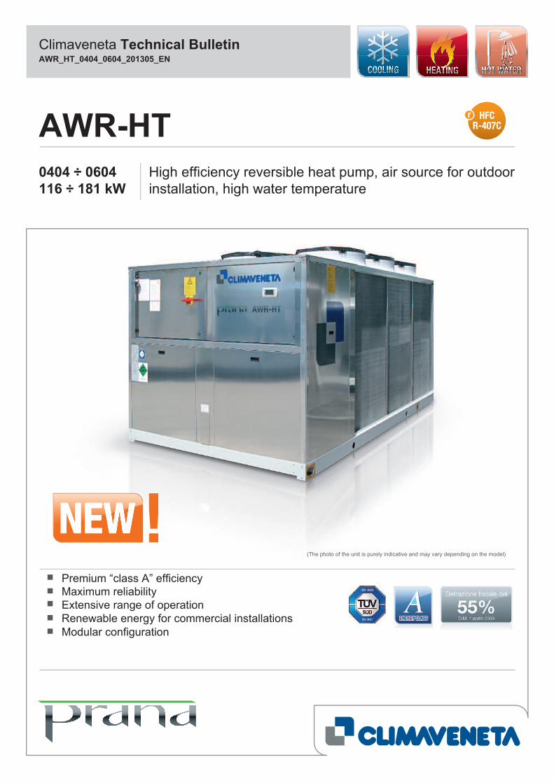
(The photo of the unit is purely indicative and may vary depending on the model)
Climaveneta Technical Bulletin
0404 ÷ 0604 High efficiency reversible heat pump, air source for outdoorinstallation, high water temperature116 ÷ 181 kW
AWR-HT
AWR-HT
SUMMARY
Waiver of liability
This publication represents a preliminary document, and is thesole property of Climaveneta. Any reproduction or disclosure ofsuch is strictly prohibited without the written authorisation of Cli-maveneta.This document has been prepared with maximum care andattention paid to the content shown. Nonetheless, Climavenetawaives all liability deriving from the use of such document.Read this document carefully.
All work must be performed, components selected and materi-als used professionally and in complete accordance with thelegislation in force in material in the country concerned, andconsidering the operating conditions and intended uses of thesystem, by qualified personnel.The data contained in this publication may be changed withoutprior notice.
HFC 407CAWR_HT_0404_0604_201305_EN2
Company quality system certified to UNI EN ISO 9001
and environmental certification UNI EN ISO 14001
1. GENERAL DESCRIPTION pg. 3
2. MODELS AND VERSIONS 4
3. ADVANTAGES OF THE HEAT PUMP 5
4. SPECIFICATIONS 8
5. CONTROL ELECTRONICS 9
6. ACCESSORIES 10
7. GENERAL TECHNICAL DATA 11
8. OPERATING LIMITS 13
9. ETHYLENE GLYCOL MIXTURE 15
10. FOULING FACTORS 15
11. HYDRAULIC DATA 16
12. HYDRONIC GROUP (Optional) 17
13. ELECTRICAL DATA 24
14. FULL LOAD SOUND LEVEL 25
15. DIMENSIONAL DRAWINGS 26
AWR-HT
1. GENERAL DESCRIPTION
AWR-HT represent the best solution for systems in which there isthe need to combine both high temperature water for space heat-ing and sanitary purposes, as well as air conditioning. With thissolution the space heating can be easily provided by using radia-tors, so without any major changes on the already existing distrib-ution system available on site. The EVI technology compressorwith additional steam injection in the compressing cycle assures awater temperature of 65°C and operating limits as low as -20°C.Neither probes nor connections pipes to wells are needed; theinstallation is simple, this is a suitable solution for all applications.
PREMIUM ´CLASS A’ EFFICIENCY
The full range is available with a premium efficiency rating, overthe Class A. AWR-HT/CA-E and AWR-HT/LN-CA-E guaranty pre-mium levels of efficiency and quietness, making this range thebest solution for both residential and light commercial markets.
MAXIMUM RELIABILITY
AWR-HT offer maximum operating reliability, thanks to their twomain features:- two independent circuits for all sizes;- system to prevent formation of ice on the coil, ensuring short-
er and more efficient defrost cycles
EXTENSIVE RANGE OF OPERATION
Production of high temperature hot water up to 65°C for spaceheating and sanitary purposes. The unit can operate as stan-dard down to -20°C outdoor temperature. The unique feature of this unit consists in the low loise operationin both summer and winter conditions, making this heat pumpthe most suitable and flexible solution for the commercial envi-ronment as well as for the most demanding residental contexts.
RENEWABLE ENERGY FOR COMMERCIAL INSTALLATIONS
Best solution in centralised residential systems such as apart-ment buildings, where the cost of renovation needs to be limitedby keeping the same distribution system with radiators, whileoffering a source of renewable energy.
MODULAR CONFIGURATION
Modular configuration with capacity extension up to about1.000kw for medium- and high-capacity installations. Ability ofmanaging different thermal loads according to the requirementsof both heating and the domestic hot water systems
CHILLED WATER PRODUCTION ONLY
The unit operates as a simple chiller and transfers the excessheat from the inside environment (heat of condensation) to theair via a finned coil heat exchanger. The system water is cooled in a freon-water plate heat exchang-er (evaporator).
HOT WATER PRODUCTION ONLY
The unit works as a heat pump that, by exploiting the heat ofthe source air via the finned coil heat exchanger, heats thewater delivered to the distribution system via a freon-water plateheat exchanger (condenser).
COMBINED PRODUCTION OF HOT AND CHILLED WATER
If the systems require simultaneous production of chilled waterand hot water for domestic use, the unit manages thechangeover in operating mode from chiller to heat pump anddeviates the flow of water to the two separate systems via athree way valve, based on the priority assigned.Changing the operating set point ensures the correct water pro-duction temperature for the different uses.Suitable storage tanks can be used for both chilled and hotwater to store the thermal energy produced for the systems,with consequent advantages in terms of running costs.
COMBINED PRODUCTION OF HOT WATER FOR HEATING
AND DOMESTIC USE
If the systems require simultaneous production of hot water forheating and for domestic use, the unit deviates the flow of waterto the two separate systems via a three way valve, based onthe priority assigned, changing the set point to ensure produc-tion of hot water with different temperatures based on the typeof use (heating or domestic).In this case too, storage tanks can be used to store the thermalenergy for the two systems, heating and domestic hot water,ensuring continuous operation by resolving the problem ofsimultaneous requests for hot water production.
AWR_HT_0404_0604_201305_EN HFC 407C3
AWR-HT
4AWR_HT_0404_0604_201305_EN HFC 407C
2. MODELS AND VERSIONS
AWR-HT/CA-E: high efficiency heat pump, reverse-cyclewith cooling operation
AWR-HT/LN-CA-E: low noise high efficiency heat pump,reverse-cycle with cooling operation
AWR-HT/D/CA-E: high efficiency heat pump, reverse-cyclewith cooling operation and partial heatrecovery
AWR-HT/D/LN-CA-E: low noise high efficiency heat pump,reverse-cycle with cooling operation andpartial heat recovery
AWR-HT: reverse-cycle heat pump with cooling operationReverse-cycle heat pump designed for outdoor installation pro-ducing chilled/hot water for the cooling/heating system and hotwater for domestic use, with vapour-injection EVI hermetic scrollcompressors operating on R407C, axial-flow fans, braze-weld-ed plate heat exchanger and thermostatic expansion valve.Peraluman external panelling and coated galvanised steelbase. The range features two compressors operating in twoseparate refrigerant circuits.
MODELS
Basic model
Standard reverse-cycle heat pump unit without heat recovery.
Model with partial heat recovery (D)
Reverse-cycle heat pump unit complete with partial heat recov-ery. In this configuration each refrigerant circuit, in addition tothe basic configuration, has a refrigerant/water heat exchangerlocated on the gas discharge line. This heat exchanger, placed in series downstream of the tradi-tional condenser in the refrigerant circuit, is suitably sized toensure heat recovery for hot water production at medium-hightemperatures, for domestic or other use. The heating capacity available is equal - as a rough approxima-tion - to compressor power consumption. Each heat exchanger is supplied as standard with frost protec-tion heater.Heat of condensation is recovered both during operation inheating mode and operation in cooling mode.
VERSIONS AVAILABLE
CA-E - Class A
High efficiency version that exceeds energy efficiency class A.
LN-CA-E - Low noise
High efficiency version in class A and low noise. This configuration features special soundproofing for the com-pressor compartments and a reduction in fan speed.Rotation speed is however automatically increased in especiallydemanding environmental conditions.The unique feature of this version consists in the low loise oper-ation in both summer and winter conditions.
AWR-HT
AWR_HT_0404_0604_201305_EN HFC 407C5
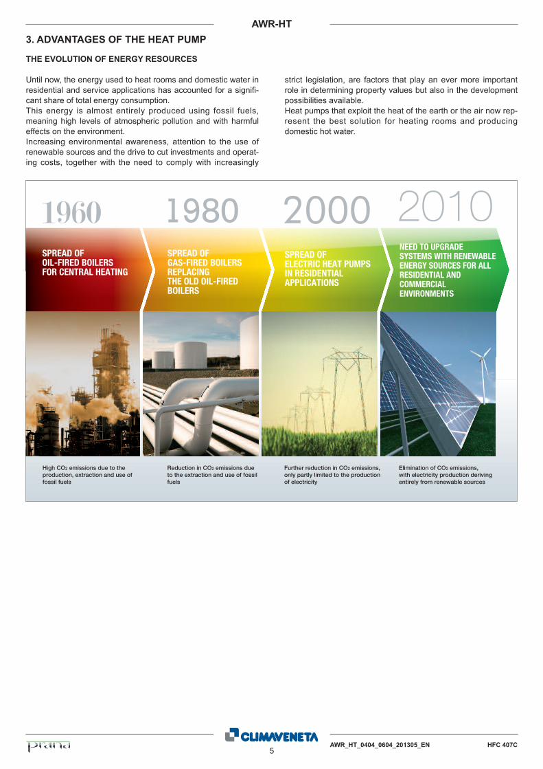
THE EVOLUTION OF ENERGY RESOURCES
Until now, the energy used to heat rooms and domestic water inresidential and service applications has accounted for a signifi-cant share of total energy consumption.This energy is almost entirely produced using fossil fuels,meaning high levels of atmospheric pollution and with harmfuleffects on the environment.Increasing environmental awareness, attention to the use ofrenewable sources and the drive to cut investments and operat-ing costs, together with the need to comply with increasingly
strict legislation, are factors that play an ever more importantrole in determining property values but also in the developmentpossibilities available.Heat pumps that exploit the heat of the earth or the air now rep-resent the best solution for heating rooms and producingdomestic hot water.
3. ADVANTAGES OF THE HEAT PUMP
SPREAD OFOIL-FIRED BOILERSFOR CENTRAL HEATING
SPREAD OFGAS-FIRED BOILERSREPLACINGTHE OLD OIL-FIREDBOILERS
SPREAD OFELECTRIC HEAT PUMPSIN RESIDENTIALAPPLICATIONS
NEED TO UPGRADESYSTEMS WITH RENEWABLEENERGY SOURCES FOR ALLRESIDENTIAL ANDCOMMERCIALENVIRONMENTS
High CO2 emissions due to theproduction, extraction and use offossil fuels
Reduction in CO2 emissions dueto the extraction and use of fossilfuels
Further reduction in CO2 emissions,only partly limited to the productionof electricity
Elimination of CO2 emissions,with electricity production derivingentirely from renewable sources
AWR-HT
6AWR_HT_0404_0604_201305_EN HFC 407C
OPERATING RELIABILITY AND CONTINUITY
The new Climaveneta heat pumps offer maximum operatingreliability, thanks to their two main features:- two independent circuits for all sizes;- system to prevent formation of ice on the coil, ensuring short-
er and more efficient defrosts.
Indeed it should be remembered that a heat pump used to heatrooms has to operate at maximum capacity when the outsideconditions are most adverse.
Typical night-time peaks in energy production must thereforealways be ensured, regardless of the outside temperature andhumidity conditions that may not allow a traditional heat pumpto operate effectively.For this reason, the Climaveneta AWR-HT units are designedand tested to ensure continuous operation and guarantee maxi-mum indoor comfort in all weather conditions.
THE IMPORTANCE OF HEAT PUMPS
High temperature heat pumps are ideal for the renovation ofbuildings where gas- or oil-fired central heating boilers need tobe replaced, however with the need to retain the existing hotwater distribution system based on radiators and, at the sametime, provide domestic hot water.This situation is typical of contexts involving public buildings,such as schools and government offices, as well as in cen-tralised residential systems such as apartment buildings, wherethe cost of renovation needs to be limited by keeping the samedistribution system while at the same time offering a source ofrenewable energy, represented by the heat pump.Renovating a building without involving the distribution systemalso solves the inconvenience relating to the building work thatwould otherwise be needed, meaning the building can still beused and consequently saving time and money.
One further advantage is represented by the possibility to usejust one compact unit to manage the production of high temper-ature hot water for central heating and for domestic use, butalso chilled water for air-conditioning in summer.This function becomes essential in hotels where just one unitcan satisfy the requirements of all the systems, ensuring theenergy needs of the entire installation completely and efficiently.
For medium- and high-capacity installations, system capacitycan be extended to about 1.000kW using a modular configura-tion. This type of installation allows differentiated managementof domestic water production so as to optimise the use of ener-gy resources without waste, likewise differentiating heatingcapacity from cooling capacity.
Its significant operating flexibility means high temperature heatpumps can be effectively used in the following applications:- centralised systems for apartments- public buildings- schools- hotels- hospitals and clinics- sports facilities and fitness centres
AWR-HT
AWR_HT_0404_0604_201305_EN HFC 407C7
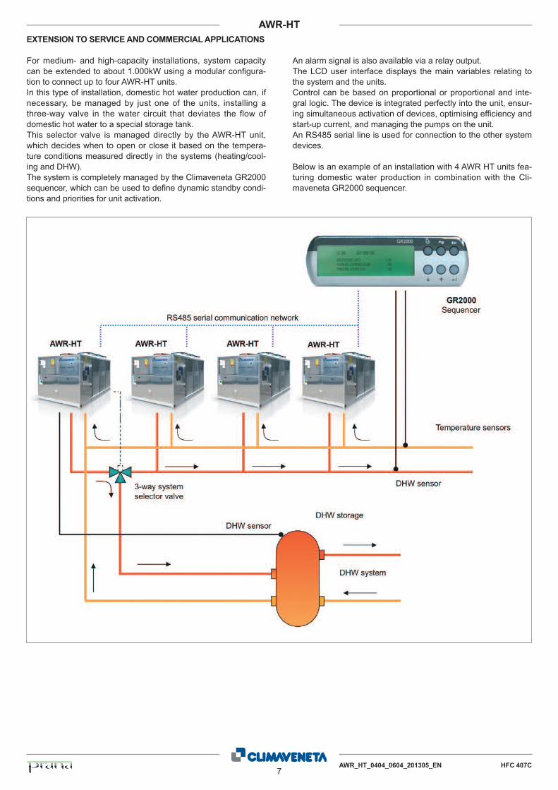
EXTENSION TO SERVICE AND COMMERCIAL APPLICATIONS
For medium- and high-capacity installations, system capacitycan be extended to about 1.000kW using a modular configura-tion to connect up to four AWR-HT units.In this type of installation, domestic hot water production can, ifnecessary, be managed by just one of the units, installing athree-way valve in the water circuit that deviates the flow ofdomestic hot water to a special storage tank.This selector valve is managed directly by the AWR-HT unit,which decides when to open or close it based on the tempera-ture conditions measured directly in the systems (heating/cool-ing and DHW).The system is completely managed by the Climaveneta GR2000sequencer, which can be used to define dynamic standby condi-tions and priorities for unit activation.
An alarm signal is also available via a relay output. The LCD user interface displays the main variables relating tothe system and the units. Control can be based on proportional or proportional and inte-gral logic. The device is integrated perfectly into the unit, ensur-ing simultaneous activation of devices, optimising efficiency andstart-up current, and managing the pumps on the unit.An RS485 serial line is used for connection to the other systemdevices.
Below is an example of an installation with 4 AWR HT units fea-turing domestic water production in combination with the Cli-maveneta GR2000 sequencer.
8AWR_HT_0404_0604_201305_EN HFC 407C
AWR-HT
DESCRIPTION
Reversible heat pump designed for outdoor installation produc-ing chilled and hot high-temperature water up to 65°C for centralheating and domestic use, with vapour-injection EVI hermeticscroll compressors operating on R407C, axial-flow fans, braze-welded plate heat exchanger and thermostatic expansion valve.Peraluman external paneling and coated galvanized steel base.Operating limit in summer mode: +40°C outdoor temperature Operating limit in winter mode: -20°C outdoor temperature
STRUCTURE
Specific structure for outdoor installation, with hot galvanizedsteel sheet base painted with polyester powder coat, perimeterframe made from aluminum section bars. Fan compartment sep-arate from the compressor compartments. Specific aluminumalloy paneling for outdoor installation, completely weatherproof,easily removable, designed to allow total access to internal com-ponents for inspection and maintenance (removal of front andside panels). Condensate collection and disposal system com-posed by double pan, insulated with closed-cell neoprene laggingand heated by dedicated electrical heaters. Double nozzle forwater expelling with a 1’1/4” diameter. Ventilation of compressorcompartments.
REFRIGERANT CIRCUIT
Main components of the refrigerant circuit: - two separated and independent circuits with two compressors
in tandem configuration on each circuit,- R407C refrigerant,- mechanical thermostatic valves,- filter dryer,- liquid flow indicator with moisture gauge, - high pressure safety valve,- low pressure safety valve - high and low pressure transducers, - high pressure safety switches, - liquid receivers, - 4-way reversing valves, - plate heat exchanger on subcooling line, - solenoid on liquid subcooling line.
COMPRESSOR
Hermetic rotary scroll compressor with vapour injection, com-plete with sump heater, electronic thermal protector with cen-tralised manual reset, two-pole electric motor.
SYSTEM HEAT EXCHANGER
Braze welded AISI 316 steel plate heat exchanger. The heatexchangers are lined on the outside with closed-cell neoprenelagging. When the unit is not operating, these are protectedagainst formation of ice on the inside by an electric heater withthermostat, while when the unit is operating protection isensured by a differential pressure switch on the water side. Theunit can also operate with non-freezing mixes, down to heatexchanger outlet temperatures of -8°C.
SOURCE HEAT EXCHANGER
Finned coil heat exchanger made from copper tubes and suit-ably spaced aluminum fins to guarantee maximum heatexchange efficiency, including subcooling circuit located in thebottom section of the coil.
POWER AND CONTROL ELECTRICAL PANEL
Power and control electrical panel, built in compliance withEN60204-1/IEC 204-1 standards, complete with: - transformer for the control circuit, - main door interlock disconnect switch, - fuses and contactors for compressors and fans. - cumulative alarm terminals (BCA), - remote ON/OFF terminals, - spring terminal blocks for control circuits, - 3 way valve control terminals, - electrical panel for outdoor installation, with two doors and
seal gaskets, - electronic controller. Unit power supply voltage: 400V~ ±10% - 50 Hz - 3N.
SOURCE FAN COMPARTMENT
Axial-flow fans with IP54 index of protection, external impeller,pressed metal blades, housed in aerodynamic tubes, completewith accident prevention grill. Six-pole electric motor with inte-grated thermal protector. Fan compartment divided into twozones to allow independent air flow for each circuit. Differentiat-ed ventilation control with fans on inactive circuit shut down.Condenser managed by continuous control of fan rotation speed.
CERTIFICATION
Unit compliant with the following directives and amendments: - Machinery Directive 2006/42/EC. - EMC 89/336/EEC + 2004/108/EC. - Low Voltage Directive 2006/95/EC. - Pressure Equipment Directive 97/23/EC. Model A1. TÜV Italy - Eurovent certification according to the program LCP/A/P/R
TESTS
Checks performed throughout the entire manufacturing processaccording to the procedures specified by ISO 9001. Perfor-mance or noise emission tests can be conducted by highlyqualified technical personnel with the customer present. Performance test involve measuring: - electrical data - water flow-rates - operating temperature - power consumption - capacity delivered - pressure drop on the water-source heat exchanger at both full
load (in rated conditions and at the most critical conditions forthe condenser) and at part load.
During performance testing the main alarm conditions can alsobe simulated. Noise emission tests verify the unit’s sound power levels accord-ing to ISO 3744.
4. SPECIFICATIONS
AWR_HT_0404_0604_201305_EN HFC 407C9
AWR-HT
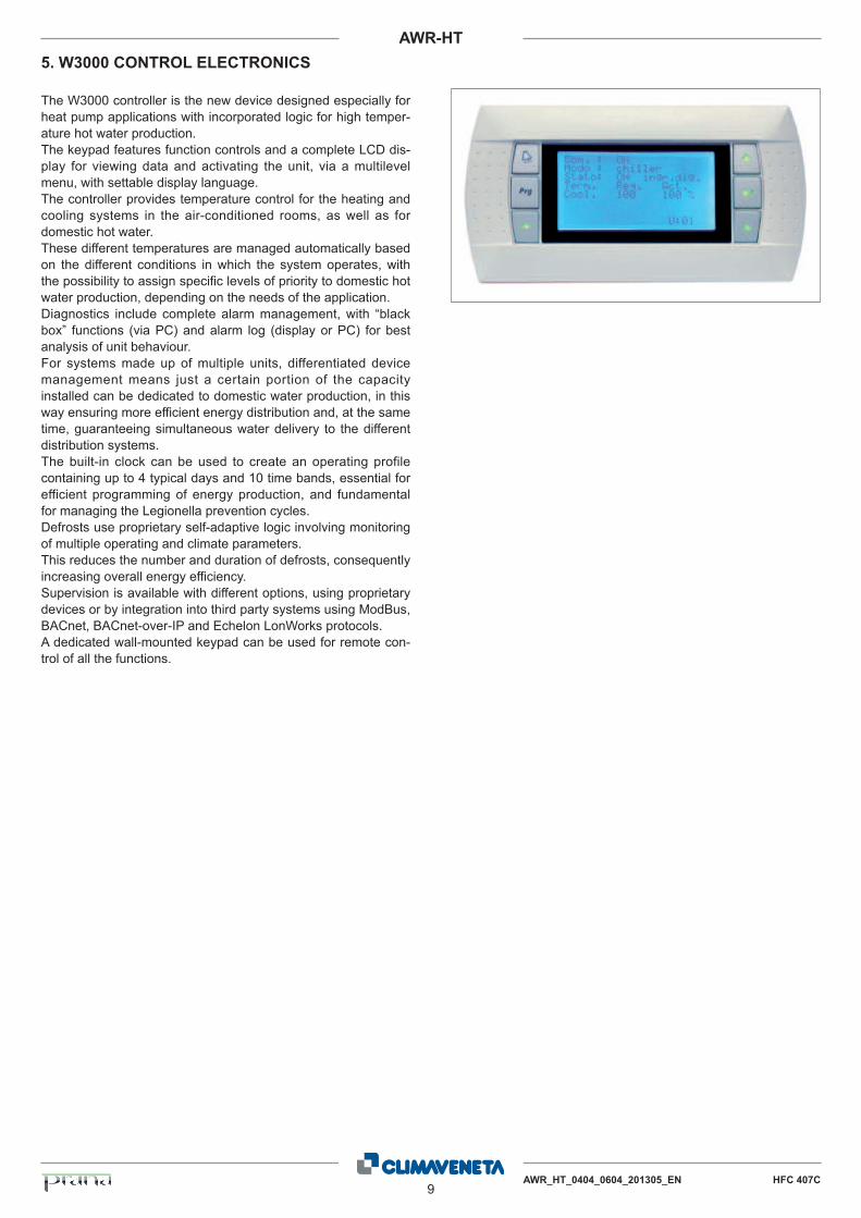
The W3000 controller is the new device designed especially forheat pump applications with incorporated logic for high temper-ature hot water production. The keypad features function controls and a complete LCD dis-play for viewing data and activating the unit, via a multilevelmenu, with settable display language.The controller provides temperature control for the heating andcooling systems in the air-conditioned rooms, as well as fordomestic hot water. These different temperatures are managed automatically basedon the different conditions in which the system operates, withthe possibility to assign specific levels of priority to domestic hotwater production, depending on the needs of the application.Diagnostics include complete alarm management, with “blackbox” functions (via PC) and alarm log (display or PC) for bestanalysis of unit behaviour.For systems made up of multiple units, differentiated devicemanagement means just a certain portion of the capacityinstalled can be dedicated to domestic water production, in thisway ensuring more efficient energy distribution and, at the sametime, guaranteeing simultaneous water delivery to the differentdistribution systems.The built-in clock can be used to create an operating profilecontaining up to 4 typical days and 10 time bands, essential forefficient programming of energy production, and fundamentalfor managing the Legionella prevention cycles.Defrosts use proprietary self-adaptive logic involving monitoringof multiple operating and climate parameters. This reduces the number and duration of defrosts, consequentlyincreasing overall energy efficiency.Supervision is available with different options, using proprietarydevices or by integration into third party systems using ModBus,BACnet, BACnet-over-IP and Echelon LonWorks protocols.A dedicated wall-mounted keypad can be used for remote con-trol of all the functions.
5. W3000 CONTROL ELECTRONICS
10AWR_HT_0404_0604_201305_EN HFC 407C
AWR-HT
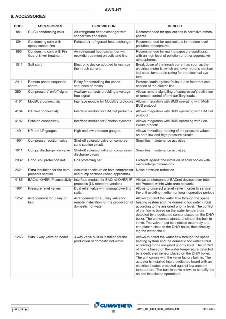
6. ACCESSORIES
CODE ACCESSORIES DESCRIPTION BENEFIT
881 Cu/Cu condensing coils Air-refrigerant heat exchanger withcopper fins and tubes.
Recommended for applications in corrosive atmos-pheres
894 Condensing coils withepoxy-coated fins
Painted air-refrigerant heat exchanger. Recommended for applications in medium levelpollution atmospheres.
895 Condensing coils with FinGuard Silver treatment
Air-refrigerant heat exchanger withepoxidic treatment on coils and fins.
Recommended for marine exposure conditions,with an high level of pollution or other aggressiveatmospheres.
1511 Soft start Electronic device adopted to managethe inrush current.
Break down of the inrush current as soon as theelectrical motor is switch on, lower motor's mechan-ical wear, favourable sizing for the electrical sys-tem.
2411 Remote phase-sequencecontrol
Relay for controlling the phase-sequence of mains.
Protects loads against faults due to incorrect con-nection of the electric line.
3601 Compressors' on/off signal Auxiliary contacts providing a voltage-free signal
Allows remote signalling of compressor's activationor remote control of any auxiliary loads.
4181 ModBUS connectivity Interface module for ModBUS protocols Allows integration with BMS operating with Mod-BUS protocol
4184 BACnet connectivity Interface module for BACnet protocols Allows integration with BMS operating with BACnetprotocol
4182 Echelon connectivity Interface module for Echelon systems Allows integration with BMS operating with Lon-Works procotls
1401 HP and LP gauges High and low pressure gauges. Allows immediate reading of the pressure valueson both low and high pressure circuits.
1901 Compressor suction valve Shut-off solenoid valve on compres-sor's suction circuit.
Simplifies maintenance activities
1911 Compr. discharge line valve Shut-off solenoid valve on compressordischarge circuit
Simplifies maintenance activities.
2032 Cond. coil protection net Coil protecting net Protects against the intrusion of solid bodies withmediumlarge dimensions.
2621 Extra insulation for the com-pressors section
Acoustic encolsure on both compressorand pump sections (when applicable)
Noise emission reduction
4185 BACnet OVER-IP connectivity Interface module for BACnet OVER-IPprotocols (LN standard version)
Allows to interconnect BACnet devices over Inter-net Protocol within wide-area networks
1961 Pressure relief valves Dual relief valve with manual divertingswitch
Allows to unselect a relief valve in order to servicethe unit avoiding medium or long inoperative periods
1252 Arrangement for 3 way onfield
Arrangement for a 3 way valve forremote installation for the production ofdomestic hot water
Allows to divert the water flow through the spaceheating system and the domestic hot water circuitaccording to the assigned priority level. The controlof the flow is based on the water temperaturedetected by a dedicated sensor placed on the DHWboiler. The unit comes standard without the built invalve. The valve must be installed externally andcan placed close to the DHW boiler, thus simplify-ing the water circuit.
1253 With 3 way valve on board 3 way valve built-in installed for theproduction of domestic hot water
Allows to divert the water flow through the spaceheating system and the domestic hot water circuitaccording to the assigned priority level. The controlof flow is based on the water temperature detectedby a dedicated sensor placed on the DHW boiler.The unit comes with the valve factory built in. Theactuator is installed into a dedicated board with anelectrical heater, protected against low ambienttemperature. The built in valve allows to simplify theon-site installation operations.
AWR_HT_0404_0604_201305_EN HFC 407C11
AWR-HT
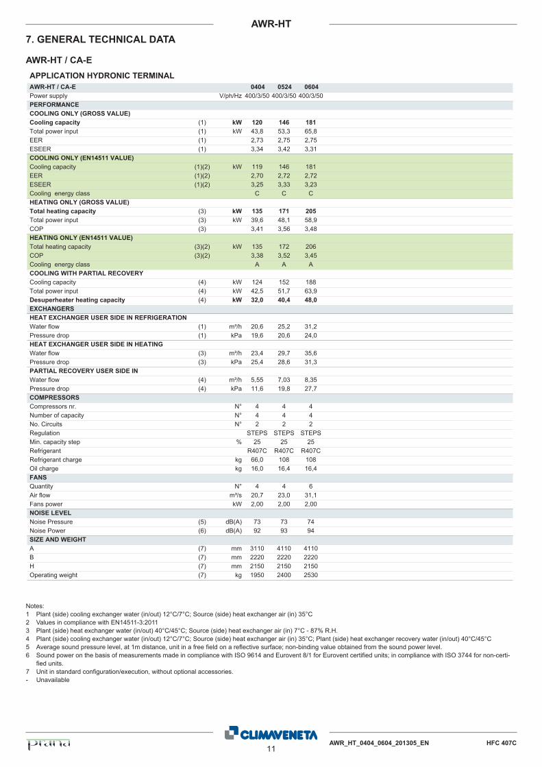
7. GENERAL TECHNICAL DATA
Notes:1 Plant (side) cooling exchanger water (in/out) 12°C/7°C; Source (side) heat exchanger air (in) 35°C2 Values in compliance with EN14511-3:20113 Plant (side) heat exchanger water (in/out) 40°C/45°C; Source (side) heat exchanger air (in) 7°C - 87% R.H.4 Plant (side) cooling exchanger water (in/out) 12°C/7°C; Source (side) heat exchanger air (in) 35°C; Plant (side) heat exchanger recovery water (in/out) 40°C/45°C5 Average sound pressure level, at 1m distance, unit in a free field on a reflective surface; non-binding value obtained from the sound power level.6 Sound power on the basis of measurements made in compliance with ISO 9614 and Eurovent 8/1 for Eurovent certified units; in compliance with ISO 3744 for non-certi-
fied units.7 Unit in standard configuration/execution, without optional accessories.- Unavailable
APPLICATION HYDRONIC TERMINALAWR-HT / CA-E 0404 0524 0604Power supply V/ph/Hz 400/3/50 400/3/50 400/3/50PERFORMANCECOOLING ONLY (GROSS VALUE)Cooling capacity (1) kW 120 146 181Total power input (1) kW 43,8 53,3 65,8EER (1) 2,73 2,75 2,75ESEER (1) 3,34 3,42 3,31COOLING ONLY (EN14511 VALUE)Cooling capacity (1)(2) kW 119 146 181EER (1)(2) 2,70 2,72 2,72ESEER (1)(2) 3,25 3,33 3,23Cooling energy class C C CHEATING ONLY (GROSS VALUE)Total heating capacity (3) kW 135 171 205Total power input (3) kW 39,6 48,1 58,9COP (3) 3,41 3,56 3,48HEATING ONLY (EN14511 VALUE)Total heating capacity (3)(2) kW 135 172 206COP (3)(2) 3,38 3,52 3,45Cooling energy class A A ACOOLING WITH PARTIAL RECOVERYCooling capacity (4) kW 124 152 188Total power input (4) kW 42,5 51,7 63,9Desuperheater heating capacity (4) kW 32,0 40,4 48,0EXCHANGERSHEAT EXCHANGER USER SIDE IN REFRIGERATIONWater flow (1) m³/h 20,6 25,2 31,2Pressure drop (1) kPa 19,6 20,6 24,0HEAT EXCHANGER USER SIDE IN HEATINGWater flow (3) m³/h 23,4 29,7 35,6Pressure drop (3) kPa 25,4 28,6 31,3PARTIAL RECOVERY USER SIDE INWater flow (4) m³/h 5,55 7,03 8,35Pressure drop (4) kPa 11,6 19,8 27,7COMPRESSORSCompressors nr. N° 4 4 4Number of capacity N° 4 4 4No. Circuits N° 2 2 2Regulation STEPS STEPS STEPSMin. capacity step % 25 25 25Refrigerant R407C R407C R407CRefrigerant charge kg 66,0 108 108Oil charge kg 16,0 16,4 16,4FANSQuantity N° 4 4 6Air flow m³/s 20,7 23,0 31,1Fans power kW 2,00 2,00 2,00NOISE LEVELNoise Pressure (5) dB(A) 73 73 74Noise Power (6) dB(A) 92 93 94SIZE AND WEIGHTA (7) mm 3110 4110 4110B (7) mm 2220 2220 2220H (7) mm 2150 2150 2150Operating weight (7) kg 1950 2400 2530
AWR-HT / CA-E

12AWR_HT_0404_0604_201305_EN HFC 407C
AWR-HT
7. GENERAL TECHNICAL DATA
Notes:1 Plant (side) cooling exchanger water (in/out) 12°C/7°C; Source (side) heat exchanger air (in) 35°C2 Values in compliance with EN14511-3:20113 Plant (side) heat exchanger water (in/out) 40°C/45°C; Source (side) heat exchanger air (in) 7°C - 87% R.H.4 Plant (side) cooling exchanger water (in/out) 12°C/7°C; Source (side) heat exchanger air (in) 35°C; Plant (side) heat exchanger recovery water (in/out) 40°C/45°C5 Average sound pressure level, at 1m distance, unit in a free field on a reflective surface; non-binding value obtained from the sound power level.6 Sound power on the basis of measurements made in compliance with ISO 9614 and Eurovent 8/1 for Eurovent certified units; in compliance with ISO 3744 for non-certi-
fied units.7 Unit in standard configuration/execution, without optional accessories.- Unavailable
APPLICATION HYDRONIC TERMINALAWR-HT / LN-CA-E 0404 0524 0604Power supply V/ph/Hz 400/3/50 400/3/50 400/3/50PERFORMANCECOOLING ONLY (GROSS VALUE)Cooling capacity (1) kW 116 145 176Total power input (1) kW 42,0 52,2 63,2EER (1) 2,77 2,77 2,78ESEER (1) 3,39 3,47 3,37COOLING ONLY (EN14511 VALUE)Cooling capacity (1)(2) kW 116 144 175EER (1)(2) 2,74 2,74 2,75ESEER (1)(2) 3,31 3,37 3,28Cooling energy class C C CHEATING ONLY (GROSS VALUE)Total heating capacity (3) kW 135 171 205Total power input (3) kW 39,6 48,1 58,9COP (3) 3,41 3,56 3,48HEATING ONLY (EN14511 VALUE)Total heating capacity (3)(2) kW 135 172 206COP (3)(2) 3,38 3,52 3,45Cooling energy class A A ACOOLING WITH PARTIAL RECOVERYCooling capacity (4) kW 121 150 182Total power input (4) kW 40,7 50,5 61,2Desuperheater heating capacity (4) kW 33,2 42,3 50,0EXCHANGERSHEAT EXCHANGER USER SIDE IN REFRIGERATIONWater flow (1) m³/h 20,0 24,9 30,3Pressure drop (1) kPa 18,5 20,1 22,6HEAT EXCHANGER USER SIDE IN HEATINGWater flow (3) m³/h 23,4 29,7 35,6Pressure drop (3) kPa 25,4 28,6 31,3PARTIAL RECOVERY USER SIDE INWater flow (4) m³/h 5,77 7,35 8,69Pressure drop (4) kPa 12,5 21,7 30,0COMPRESSORSCompressors nr. N° 4 4 4Number of capacity N° 4 4 4No. Circuits N° 2 2 2Regulation STEPS STEPS STEPSMin. capacity step % 25 25 25Refrigerant R407C R407C R407CRefrigerant charge kg 66,0 108 108Oil charge kg 16,0 16,4 16,4FANSQuantity N° 4 4 6Air flow m³/s 15,8 18,0 23,7Fans power kW 1,20 1,20 1,20NOISE LEVELNoise Pressure (5) dB(A) 67 66 67Noise Power (6) dB(A) 86 86 87SIZE AND WEIGHTA (7) mm 3110 4110 4110B (7) mm 2220 2220 2220H (7) mm 2150 2150 2150Operating weight (7) kg 1960 2410 2540
AWR-HT / LN-CA-E
AWR_HT_0404_0604_201305_EN HFC 407C13
AWR-HT
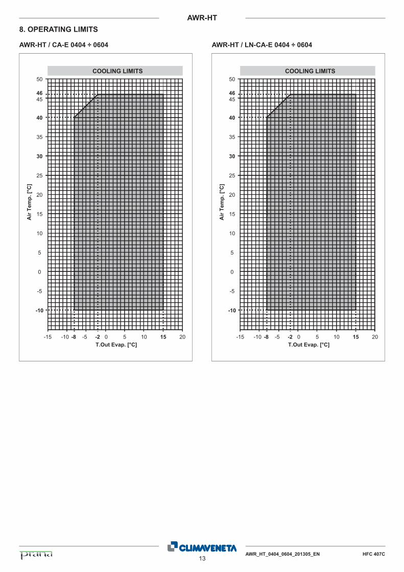
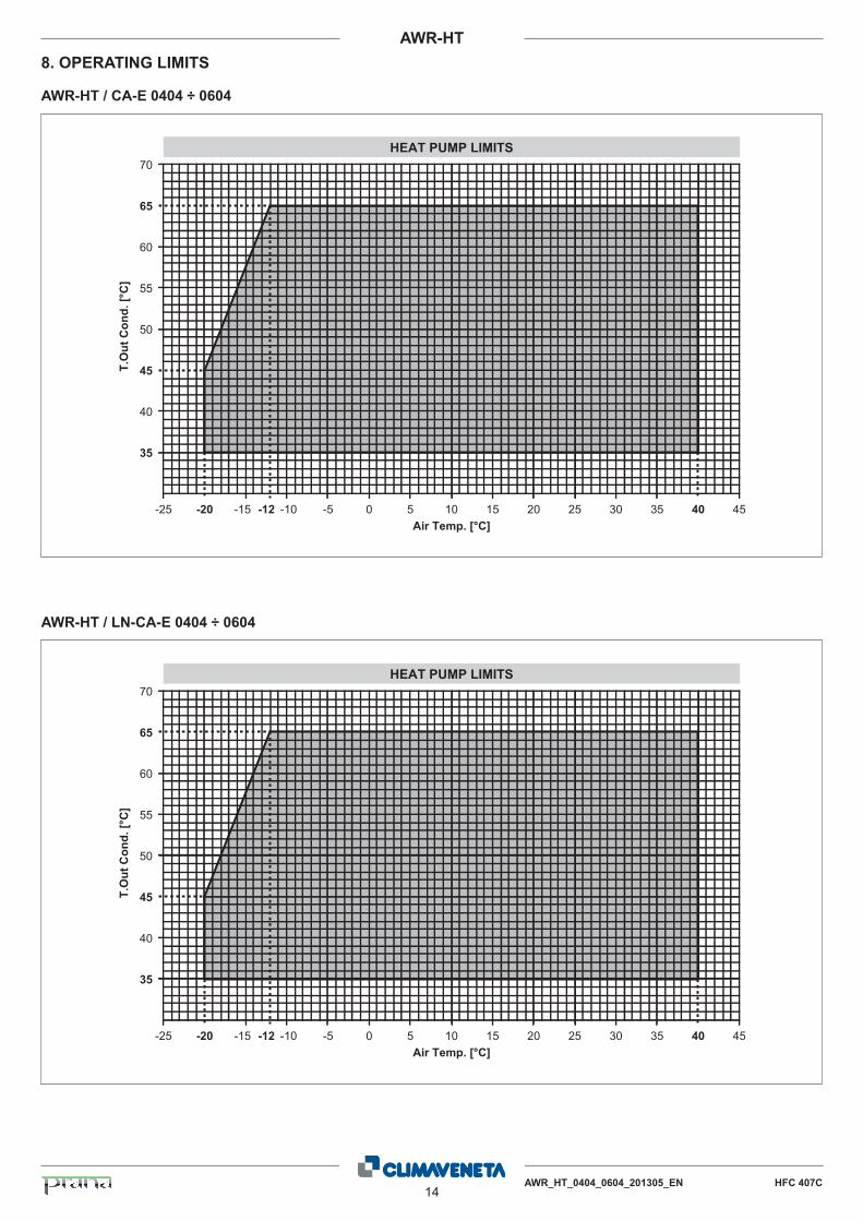
8. OPERATING LIMITS
AWR-HT / CA-E 0404 ÷ 0604 AWR-HT / LN-CA-E 0404 ÷ 0604
-15
20
15
10
5
0
-5
-10
25
30
35
40
4546
50
-10 -5-8 0-2 5 10 15 20
COOLING LIMITS
T.Out Evap. [°C]
Air
Tem
p. [°
C]
-15
20
15
10
5
0
-5
-10
25
30
35
40
4546
50
-10 -5-8 0-2 5 10 15 20
COOLING LIMITS
T.Out Evap. [°C]
Air
Tem
p. [°
C]
14AWR_HT_0404_0604_201305_EN HFC 407C
AWR-HT
8. OPERATING LIMITS
AWR-HT / CA-E 0404 ÷ 0604
AWR-HT / LN-CA-E 0404 ÷ 0604
-25
35
40
45
50
55
60
65
70
-20 -15 -10-12 -5 0 5 10 15 20 25 30 35 40 45
HEAT PUMP LIMITS
Air Temp. [°C]
T.O
ut C
ond.
[°C
]
-25
35
40
45
50
55
60
65
70
-20 -15 -10-12 -5 0 5 10 15 20 25 30 35 40 45
HEAT PUMP LIMITS
Air Temp. [°C]
T.O
ut C
ond.
[°C
]
AWR_HT_0404_0604_201305_EN HFC 407C15
AWR-HT
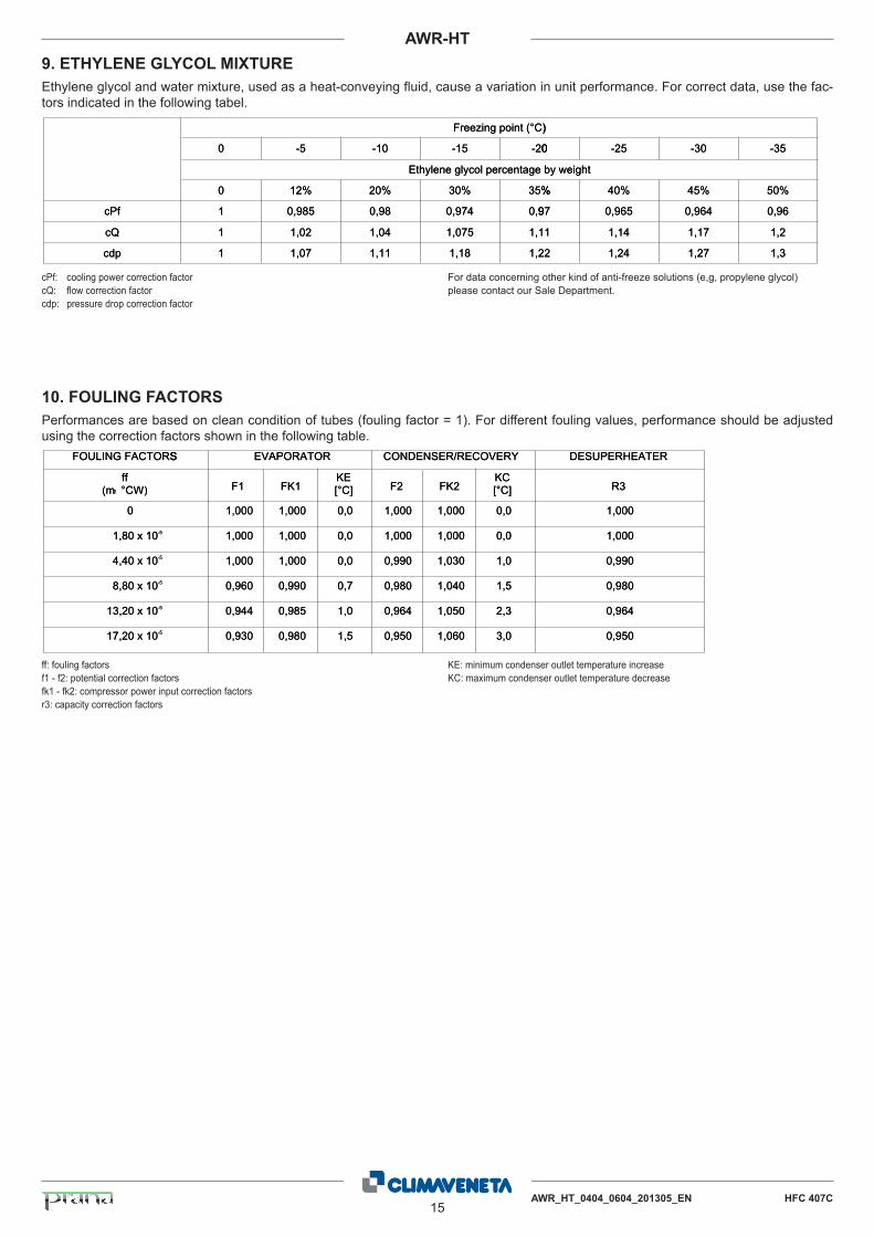
9. ETHYLENE GLYCOL MIXTURE
Ethylene glycol and water mixture, used as a heat-conveying fluid, cause a variation in unit performance. For correct data, use the fac-tors indicated in the following tabel.
cPf: cooling power correction factorcQ: flow correction factorcdp: pressure drop correction factor
For data concerning other kind of anti-freeze solutions (e,g, propylene glycol)please contact our Sale Department.
ff: fouling factorsf1 - f2: potential correction factorsfk1 - fk2: compressor power input correction factorsr3: capacity correction factors
KE: minimum condenser outlet temperature increaseKC: maximum condenser outlet temperature decrease
10. FOULING FACTORS
Performances are based on clean condition of tubes (fouling factor = 1). For different fouling values, performance should be adjustedusing the correction factors shown in the following table.
0 -5 -10 -15 -20 -25 -30 -35
50% 45% 40% 35% 30% 20% 12% 0
0,96 0,964 0,965 0,97 0,974 0,98 0,985 1
1,2 1,17 1,14 1,11 1,075 1,04 1,02 1
1,3 1,27 1,24 1,22 1,18 1,11 1,07 1 cdp
cQ
cPf
Freezing point (°C)
Ethylene glycol percentage by weight
pdc
Qc
fPc
0 -5
%210
589,01
20,11
70,11
- 01 - 51 - 02
%53%03%02
9,0479,089,0
1,1570,140,1
2,181,111,1
(tniopgnizeerF ° )C
egatnecreplocylgenelyhtE
0 - 52 - 03
%54%04%
469,0569,079
71,141,11
72,1,1 422
)
thgiewyb
- 53
%05
69,0
2,1
3,1
FOULING FACTORS EVAPORATOR CONDENSER/RECOVERY DESUPERHEATER
2 ff
(m °CW) F1 FK1 F2 FK2 KC [°C] R3
KE [°C]
1,000 1,000 0,0 1,000 1,000 0,0 1,000 0
1,000 1,000 0,0 1,000 1,000 0,0 1,000 1,80 x 10 -5
1,000 1,000 0,0 0,990 1,030 1,0 0,990 4,40 x 10 -5
0,960 0,990 0,7 0,980 1,040 1,5 0,980 8,80 x 10 -5
0,944 0,985 1,0 0,964 1,050 2,3 0,964 13,20 x 10 -5
0,930 0,980 1,5 0,950 1,060 3,0 0,950 17,20 x 10 -5
2m W)
SROTCAFGNILUOF
ffm2( ° )WC
0
01x08,1-5
S ROTAROPAVE
1F 1KFEK
[° ]C
000,1 000,1 0,0
000,1 000,1 0,0
YREVOCER/RESNEDNOC
2F 2KFCK
[° ]C
000,1 000,1 0,0
000,1 000,1 0,0
RETAEHREPUSED
3R
000,1
000,1
01x04,4-5
01x08,8-5
01x02,31-5
01x02,71-5
000,1 000,1 0,0
069,0 099,0 7,0
449,0 589,0 0,1
039,0 089,0 5,1
099,0 030,1 0,1
089,0 040,1 5,1
469,0 050,1 3,2
059,0 060,1 0,3
099,0
089,0
469,0
059,0
16AWR_HT_0404_0604_201305_EN HFC 407C
AWR-HT
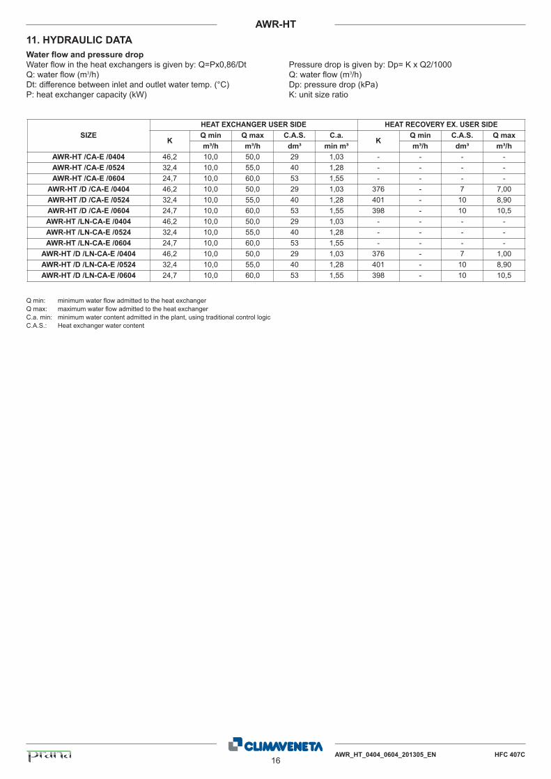
11. HYDRAULIC DATA
Water flow and pressure drop
Water flow in the heat exchangers is given by: Q=Px0,86/DtQ: water flow (m3/h)Dt: difference between inlet and outlet water temp. (°C)P: heat exchanger capacity (kW)
Pressure drop is given by: Dp= K x Q2/1000Q: water flow (m3/h)Dp: pressure drop (kPa)K: unit size ratio
Q min: minimum water flow admitted to the heat exchangerQ max: maximum water flow admitted to the heat exchangerC.a. min: minimum water content admitted in the plant, using traditional control logicC.A.S.: Heat exchanger water content
SIZE
HEAT EXCHANGER USER SIDE HEAT RECOVERY EX. USER SIDE
KQ min Q max C.A.S. C.a.
KQ min C.A.S. Q max
m³/h m³/h dm³ min m³ m³/h dm³ m³/h
AWR-HT /CA-E /0404 46,2 10,0 50,0 29 1,03 - - - -
AWR-HT /CA-E /0524 32,4 10,0 55,0 40 1,28 - - - -
AWR-HT /CA-E /0604 24,7 10,0 60,0 53 1,55 - - - -
AWR-HT /D /CA-E /0404 46,2 10,0 50,0 29 1,03 376 - 7 7,00
AWR-HT /D /CA-E /0524 32,4 10,0 55,0 40 1,28 401 - 10 8,90
AWR-HT /D /CA-E /0604 24,7 10,0 60,0 53 1,55 398 - 10 10,5
AWR-HT /LN-CA-E /0404 46,2 10,0 50,0 29 1,03 - - - -
AWR-HT /LN-CA-E /0524 32,4 10,0 55,0 40 1,28 - - - -
AWR-HT /LN-CA-E /0604 24,7 10,0 60,0 53 1,55 - - - -
AWR-HT /D /LN-CA-E /0404 46,2 10,0 50,0 29 1,03 376 - 7 1,00
AWR-HT /D /LN-CA-E /0524 32,4 10,0 55,0 40 1,28 401 - 10 8,90
AWR-HT /D /LN-CA-E /0604 24,7 10,0 60,0 53 1,55 398 - 10 10,5
AWR_HT_0404_0604_201305_EN HFC 407C17
AWR-HT
12. HYDRONIC GROUP (Optional)
The units can be supplied with a hydronic group. This housesall the main hydraulic components, thereby optimising hydraulicand electric installation space, time and cost.
Available pump configurations:
- Hydronic kit with one IN-LINE 2-pole low-head pump- Hydronic kit with one IN-LINE 2-pole high-head pump- Hydronic kit with IN-LINE 2-pole low-head twin pumps- Hydronic kit with IN-LINE 2-pole high-head twin pumps
2-pole low head pump
Centrifugal pumps with in-line suction and delivery flanges, insingle and twin versions. Pump body in cast iron and impeller inAISI 316L stainless steel or cast-iron, entirely laser technologywelded. Mechanical seal with components in ceramics, carbonand EPDM elastomers. Three-phase electric motor protected toIP55, insulation class F, suitable for continuous service.
2-pole high-head pump
All versions of the hydronic unit can be supplied with a highhead pump. In these cases, the pump features a two-polemotor even in the silent-running versions.
Twin pump
A second stand-by pump for high or low pressures is availableon request. The pumps are automatically exchanged on thebasis of a rotation programme and the stand-by pump cuts inautomatically if the primary pump fails.
GENERAL CHARACTERISTICS
Water connections
In the units without pumps, standard version, the connectionsfor the water inlet and outlet both in the evaporator and in thedesuperheater are inside the unit. As an accessory one canrequest these connections flush with the unit.For units with pumps, the connections are always flush with theunit.
3 way valve kit
Three way valve for the prodiction of domesti hot water (DHW)including water temperature sensor, voltage-free contact foractivating an integrating external heating source (gas boiler orelectrical heater). The kit comes with or without the 3 way valvefactory built-in.
Water-side mechanical filter (optional)
Y-filter designed and built to capture the impurities in thehydraulic circuit. It is fitted with a 0.9 mm stainless steel meshcartridge which can be replaced without removing the valve bodyfrom the piping.
Unit electrical panel
The unit electrical panel is fitted with fuses and a circuit breakercontactor.
Special pumps
For pumps with different configurations, please contact oursales department.
Additional components
The supply does not include the following accessories thoughthese are recommended to ensure correct system operation:- MA Pressure gauges upline and downline from the unit- GF Flexible joints on piping- RI On-off valves- T Outlet control thermometer
18AWR_HT_0404_0604_201305_EN HFC 407C
AWR-HT
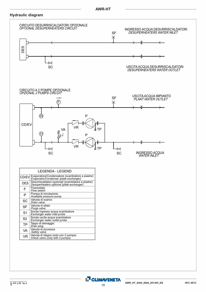
Hydraulic diagram
Sonda ingresso acqua scambiatore Exchanger water inlet probe
LEGENDA - LEGEND
SC
S1
S2 Sonda uscita acqua scambiatoreExchanger water outlet probe
CD/EV
Drain valveValvola di scarico
Evaporator/Condenser (plate exchanger)Evaporatore/Condensatore (scambiatore a piastre)
SF Purge valveValvola di sfiato
S2
S1
CD/EV
SF
SC
SF
SC
DE
S
DES Desuperheaters optional (plate exchanger)Desurriscaldatori opzionali (scambiatore a piastre)
CIRCUITO DESURRISCALDATORI OPZIONALEOPTIONAL DESUPERHEATERS CIRCUIT
F
FlussostatoFlow switchF
INGRESSO ACQUAWATER INLET
USCITA ACQUA IMPIANTOPLANT WATER OUTLET
INGRESSO ACQUA DESURRISCALDATORIDESUPERHEATERS WATER INLET
USCITA ACQUA DESURRISCALDATORIDESUPERHEATERS WATER OUTLET
VR
VR
PTP
TP
CIRCUITO A 2 POMPE OPZIONALEOPZIONAL 2 PUMPS CIRCUIT
P
SC
VA
Available pressure pumpPompa di circolazioneP
Drain plugTappo di drenaggio
Safety valveValvola di sicurezzaVA
TP
Valvola di ritegno (solo con 2 pompe)Check valve (only with 2 pumps)VR
AWR_HT_0404_0604_201305_EN HFC 407C19
AWR-HT
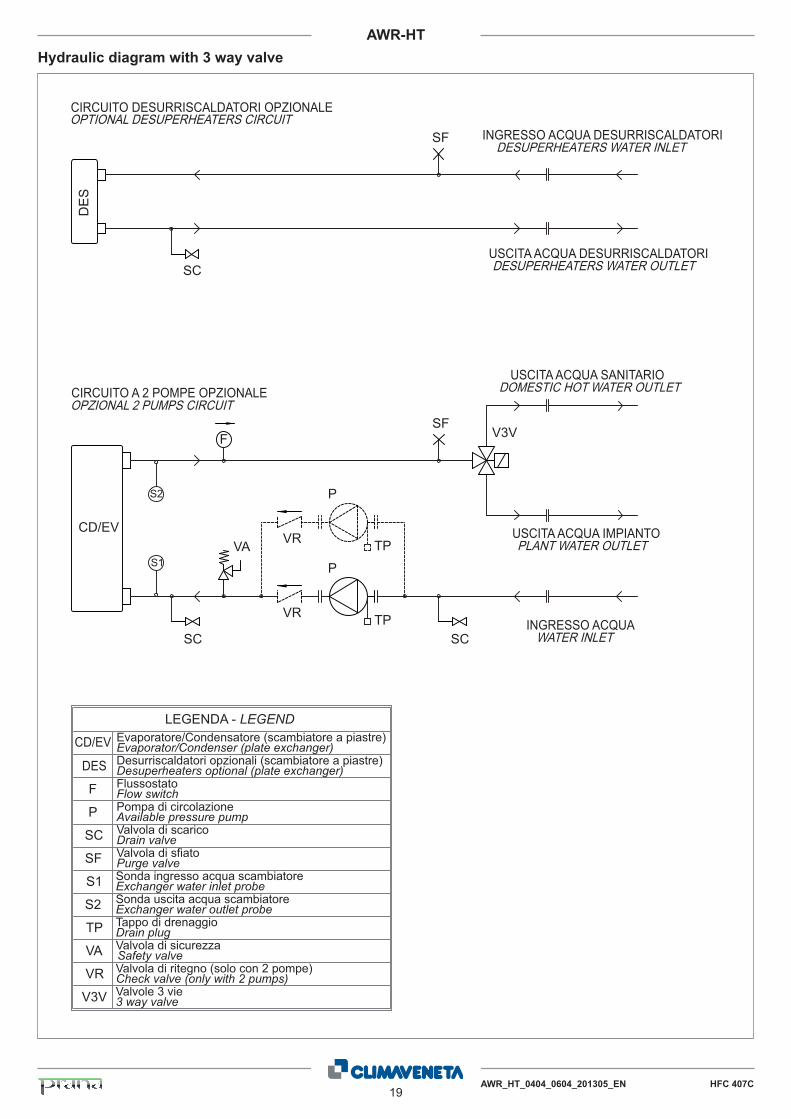
Hydraulic diagram with 3 way valve
Sonda ingresso acqua scambiatore Exchanger water inlet probe
LEGENDA - LEGEND
SC
S1
S2 Sonda uscita acqua scambiatoreExchanger water outlet probe
CD/EV
Drain valveValvola di scarico
Evaporator/Condenser (plate exchanger)Evaporatore/Condensatore (scambiatore a piastre)
SF Purge valveValvola di sfiato
S2
S1
CD/EV
SC
SF
SC
DE
S
DES Desuperheaters optional (plate exchanger)Desurriscaldatori opzionali (scambiatore a piastre)
CIRCUITO DESURRISCALDATORI OPZIONALEOPTIONAL DESUPERHEATERS CIRCUIT
F
FlussostatoFlow switchF
INGRESSO ACQUAWATER INLET
INGRESSO ACQUA DESURRISCALDATORIDESUPERHEATERS WATER INLET
USCITA ACQUA DESURRISCALDATORIDESUPERHEATERS WATER OUTLET
VR
VR
P
TP
TP
CIRCUITO A 2 POMPE OPZIONALEOPZIONAL 2 PUMPS CIRCUIT
P
SC
VA
Available pressure pumpPompa di circolazioneP
Drain plugTappo di drenaggio
Safety valveValvola di sicurezzaVA
TP
Valvola di ritegno (solo con 2 pompe)Check valve (only with 2 pumps)VR
SF
USCITA ACQUA SANITARIODOMESTIC HOT WATER OUTLET
USCITA ACQUA IMPIANTOPLANT WATER OUTLET
V3V
V3V Valvole 3 vie3 way valve
20AWR_HT_0404_0604_201305_EN HFC 407C
AWR-HT
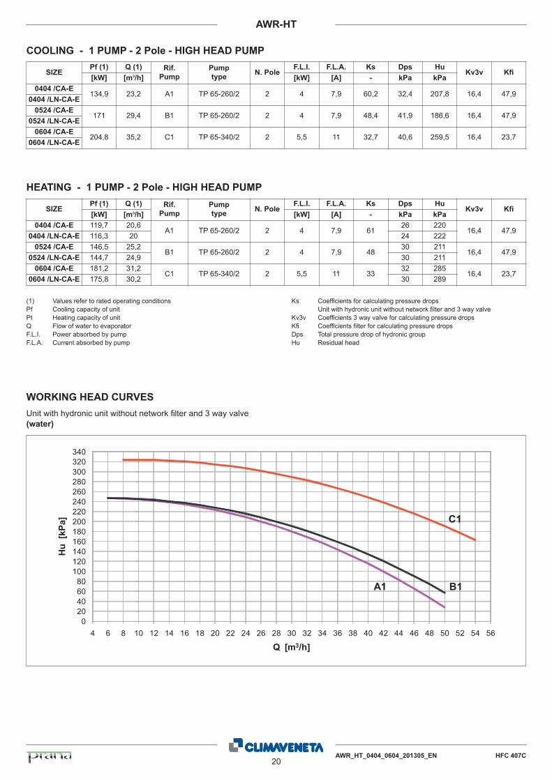
COOLING - 1 PUMP - 2 Pole - HIGH HEAD PUMP
SIZEPf (1) Q (1) Rif.
Pump
Pump
typeN. Pole
F.L.I. F.L.A. Ks Dps HuKv3v Kfi
[kW] [m3/h] [kW] [A] - kPa kPa
0404 /CA-E134,9 23,2 A1 TP 65-260/2 2 4 7,9 60,2 32,4 207,8 16,4 47,9
0404 /LN-CA-E
0524 /CA-E171 29,4 B1 TP 65-260/2 2 4 7,9 48,4 41,9 186,6 16,4 47,9
0524 /LN-CA-E
0604 /CA-E204,8 35,2 C1 TP 65-340/2 2 5,5 11 32,7 40,6 259,5 16,4 23,7
0604 /LN-CA-E
SIZEPf (1) Q (1) Rif.
Pump
Pump
typeN. Pole
F.L.I. F.L.A. Ks Dps HuKv3v Kfi
[kW] [m3/h] [kW] [A] - kPa kPa
0404 /CA-E 119,7 20,6A1 TP 65-260/2 2 4 7,9 61
26 22016,4 47,9
0404 /LN-CA-E 116,3 20 24 222
0524 /CA-E 146,5 25,2B1 TP 65-260/2 2 4 7,9 48
30 21116,4 47,9
0524 /LN-CA-E 144,7 24,9 30 211
0604 /CA-E 181,2 31,2C1 TP 65-340/2 2 5,5 11 33
32 28516,4 23,7
0604 /LN-CA-E 175,8 30,2 30 289
HEATING - 1 PUMP - 2 Pole - HIGH HEAD PUMP
(1) Values refer to rated operating conditions Pf Cooling capacity of unit Pt Heating capacity of unit Q Flow of water to evaporator F.L.I. Power absorbed by pump F.L.A. Current absorbed by pump
Ks Coefficients for calculating pressure dropsUnit with hydronic unit without network filter and 3 way valve
Kv3v Coefficients 3 way valve for calculating pressure dropsKfi Coefficients filter for calculating pressure dropsDps Total pressure drop of hydronic group Hu Residual head
020406080100120140160180200220240260280300320340
4 6 8 10 12 14 16 18 20 22 24 26 28 30 32 34 36 38 40 42 44 46 48 50 52 54 56
Hu
[kPa
]
Q [m3/h]
A1 B1
C1
WORKING HEAD CURVES
Unit with hydronic unit without network filter and 3 way valve(water)
AWR_HT_0404_0604_201305_EN HFC 407C21
AWR-HT
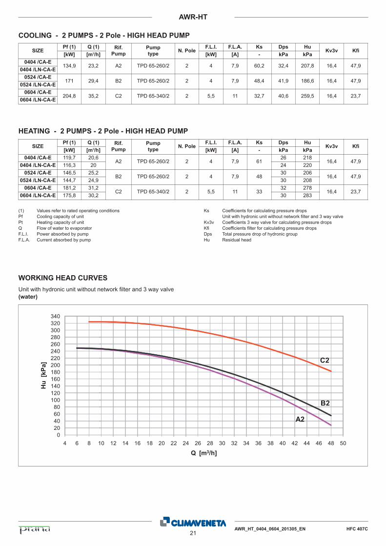
COOLING - 2 PUMPS - 2 Pole - HIGH HEAD PUMP
SIZEPf (1) Q (1) Rif.
Pump
Pump
typeN. Pole
F.L.I. F.L.A. Ks Dps HuKv3v Kfi
[kW] [m3/h] [kW] [A] - kPa kPa
0404 /CA-E134,9 23,2 A2 TPD 65-260/2 2 4 7,9 60,2 32,4 207,8 16,4 47,9
0404 /LN-CA-E
0524 /CA-E171 29,4 B2 TPD 65-260/2 2 4 7,9 48,4 41,9 186,6 16,4 47,9
0524 /LN-CA-E
0604 /CA-E204,8 35,2 C2 TPD 65-340/2 2 5,5 11 32,7 40,6 259,5 16,4 23,7
0604 /LN-CA-E
SIZEPf (1) Q (1) Rif.
Pump
Pump
typeN. Pole
F.L.I. F.L.A. Ks Dps HuKv3v Kfi
[kW] [m3/h] [kW] [A] - kPa kPa
0404 /CA-E 119,7 20,6A2 TPD 65-260/2 2 4 7,9 61
26 21816,4 47,9
0404 /LN-CA-E 116,3 20 24 220
0524 /CA-E 146,5 25,2B2 TPD 65-260/2 2 4 7,9 48
30 20616,4 47,9
0524 /LN-CA-E 144,7 24,9 30 208
0604 /CA-E 181,2 31,2C2 TPD 65-340/2 2 5,5 11 33
32 27816,4 23,7
0604 /LN-CA-E 175,8 30,2 30 283
HEATING - 2 PUMPS - 2 Pole - HIGH HEAD PUMP
(1) Values refer to rated operating conditions Pf Cooling capacity of unit Pt Heating capacity of unit Q Flow of water to evaporator F.L.I. Power absorbed by pump F.L.A. Current absorbed by pump
Ks Coefficients for calculating pressure dropsUnit with hydronic unit without network filter and 3 way valve
Kv3v Coefficients 3 way valve for calculating pressure dropsKfi Coefficients filter for calculating pressure dropsDps Total pressure drop of hydronic group Hu Residual head
020406080100120140160180200220240260280300320340
4 6 8 10 12 14 16 18 20 22 24 26 28 30 32 34 36 38 40 42 44 46 48 50
Hu
[kPa
]
Q [m3/h]
A2
B2
C2
WORKING HEAD CURVES
Unit with hydronic unit without network filter and 3 way valve(water)
22AWR_HT_0404_0604_201305_EN HFC 407C
AWR-HT
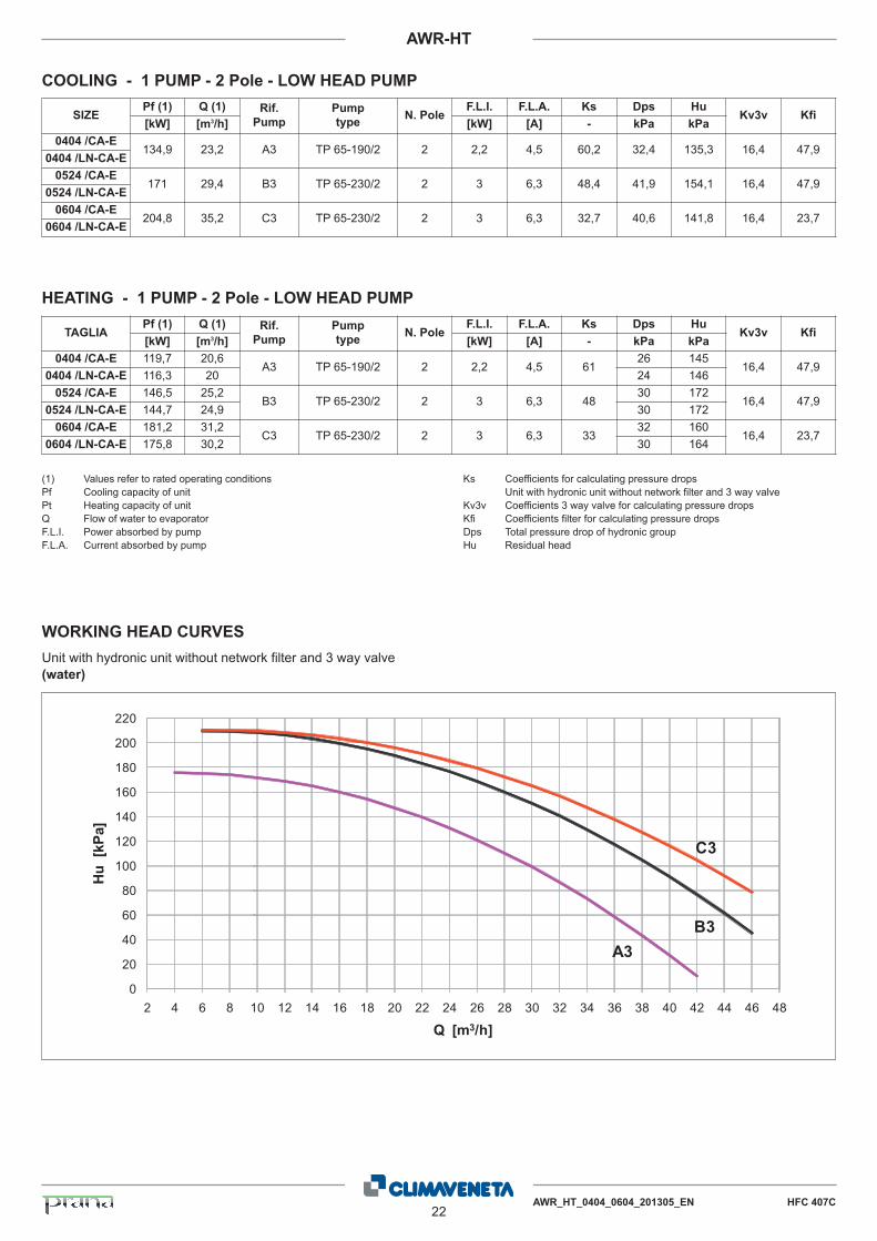
COOLING - 1 PUMP - 2 Pole - LOW HEAD PUMP
SIZEPf (1) Q (1) Rif.
Pump
Pump
typeN. Pole
F.L.I. F.L.A. Ks Dps HuKv3v Kfi
[kW] [m3/h] [kW] [A] - kPa kPa
0404 /CA-E134,9 23,2 A3 TP 65-190/2 2 2,2 4,5 60,2 32,4 135,3 16,4 47,9
0404 /LN-CA-E
0524 /CA-E171 29,4 B3 TP 65-230/2 2 3 6,3 48,4 41,9 154,1 16,4 47,9
0524 /LN-CA-E
0604 /CA-E204,8 35,2 C3 TP 65-230/2 2 3 6,3 32,7 40,6 141,8 16,4 23,7
0604 /LN-CA-E
TAGLIAPf (1) Q (1) Rif.
Pump
Pump
typeN. Pole
F.L.I. F.L.A. Ks Dps HuKv3v Kfi
[kW] [m3/h] [kW] [A] - kPa kPa
0404 /CA-E 119,7 20,6A3 TP 65-190/2 2 2,2 4,5 61
26 14516,4 47,9
0404 /LN-CA-E 116,3 20 24 146
0524 /CA-E 146,5 25,2B3 TP 65-230/2 2 3 6,3 48
30 17216,4 47,9
0524 /LN-CA-E 144,7 24,9 30 172
0604 /CA-E 181,2 31,2C3 TP 65-230/2 2 3 6,3 33
32 16016,4 23,7
0604 /LN-CA-E 175,8 30,2 30 164
HEATING - 1 PUMP - 2 Pole - LOW HEAD PUMP
(1) Values refer to rated operating conditions Pf Cooling capacity of unit Pt Heating capacity of unit Q Flow of water to evaporator F.L.I. Power absorbed by pump F.L.A. Current absorbed by pump
Ks Coefficients for calculating pressure dropsUnit with hydronic unit without network filter and 3 way valve
Kv3v Coefficients 3 way valve for calculating pressure dropsKfi Coefficients filter for calculating pressure dropsDps Total pressure drop of hydronic group Hu Residual head
0
20
40
60
80
100
120
140
160
180
200
220
2 4 6 8 10 12 14 16 18 20 22 24 26 28 30 32 34 36 38 40 42 44 46 48
Hu
[kPa
]
Q [m3/h]
C3
B3A3
WORKING HEAD CURVES
Unit with hydronic unit without network filter and 3 way valve (water)
AWR_HT_0404_0604_201305_EN HFC 407C23
AWR-HT
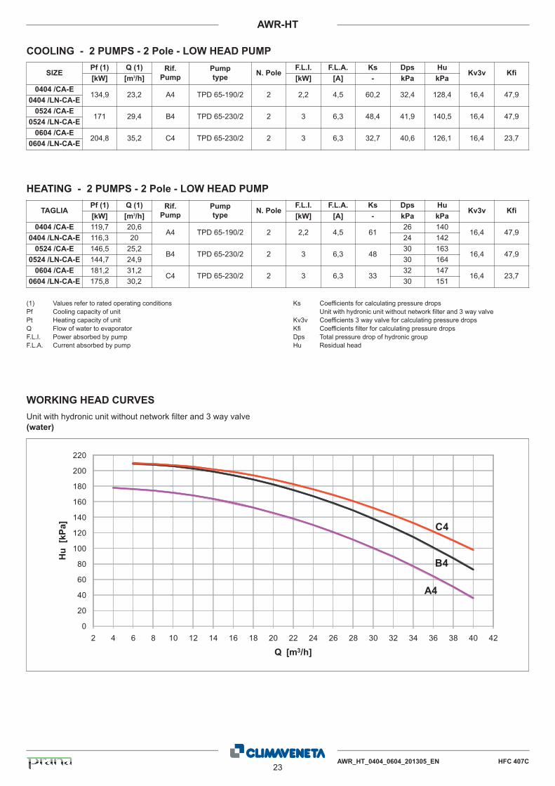
COOLING - 2 PUMPS - 2 Pole - LOW HEAD PUMP
SIZEPf (1) Q (1) Rif.
Pump
Pump
typeN. Pole
F.L.I. F.L.A. Ks Dps HuKv3v Kfi
[kW] [m3/h] [kW] [A] - kPa kPa
0404 /CA-E134,9 23,2 A4 TPD 65-190/2 2 2,2 4,5 60,2 32,4 128,4 16,4 47,9
0404 /LN-CA-E
0524 /CA-E171 29,4 B4 TPD 65-230/2 2 3 6,3 48,4 41,9 140,5 16,4 47,9
0524 /LN-CA-E
0604 /CA-E204,8 35,2 C4 TPD 65-230/2 2 3 6,3 32,7 40,6 126,1 16,4 23,7
0604 /LN-CA-E
TAGLIAPf (1) Q (1) Rif.
Pump
Pump
typeN. Pole
F.L.I. F.L.A. Ks Dps HuKv3v Kfi
[kW] [m3/h] [kW] [A] - kPa kPa
0404 /CA-E 119,7 20,6A4 TPD 65-190/2 2 2,2 4,5 61
26 14016,4 47,9
0404 /LN-CA-E 116,3 20 24 142
0524 /CA-E 146,5 25,2B4 TPD 65-230/2 2 3 6,3 48
30 16316,4 47,9
0524 /LN-CA-E 144,7 24,9 30 164
0604 /CA-E 181,2 31,2C4 TPD 65-230/2 2 3 6,3 33
32 14716,4 23,7
0604 /LN-CA-E 175,8 30,2 30 151
HEATING - 2 PUMPS - 2 Pole - LOW HEAD PUMP
(1) Values refer to rated operating conditions Pf Cooling capacity of unit Pt Heating capacity of unit Q Flow of water to evaporator F.L.I. Power absorbed by pump F.L.A. Current absorbed by pump
Ks Coefficients for calculating pressure dropsUnit with hydronic unit without network filter and 3 way valve
Kv3v Coefficients 3 way valve for calculating pressure dropsKfi Coefficients filter for calculating pressure dropsDps Total pressure drop of hydronic group Hu Residual head
0
20
40
60
80
100
120
140
160
180
200
220
2 4 6 8 10 12 14 16 18 20 22 24 26 28 30 32 34 36 38 40 42
Hu
[kPa
]
Q [m3/h]
A4
B4
C4
WORKING HEAD CURVES
Unit with hydronic unit without network filter and 3 way valve(water)
24AWR_HT_0404_0604_201305_EN HFC 407C
AWR-HT
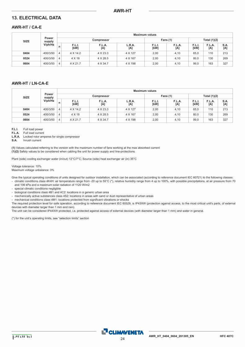
13. ELECTRICAL DATA
Maximum values
Compressor Fans (1) Total (1)(2)
n F.L.I.[kW]
F.L.A.[A]
L.R.A.[A]
F.L.I.[kW]
F.L.A.[A]
F.L.I.[kW]
F.L.A.[A]
S.A.[A]
SIZEPowersupplyV/ph/Hz
0404 400/3/50 4 4 X 14.2 4 X 23.3 4 X 127 2,00 4,10 11065,0 213
0524 400/3/50 4 4 X 18 4 X 28.5 4 X 167 2,00 4,10 13080,0 269
0604 400/3/50 4 4 X 21.7 4 X 34.7 4 X 198 2,00 4,10 16399,0 327
AWR-HT / CA-E
AWR-HT / LN-CA-E
F.L.I. Full load powerF.L.A. Full load currentL.R.A. Locked rotor amperes for single compressorS.A. Inrush current
(1) Values calculated referring to the version with the maximum number of fans working at the max absorbed current(1)(2) Safety values to be considered when cabling the unit for power supply and line-protections
Plant (side) cooling exchanger water (in/out) 12°C/7°C; Source (side) heat exchanger air (in) 35°C
Voltage tolerance: 10%Maximum voltage unbalance: 3%
Give the typical operating conditions of units designed for outdoor installation, which can be associated (according to reference document IEC 60721) to the following classes:- climatic conditions class 4K4H: air temperature range from -20 up to 55°C (*), relative humidity range from 4 up to 100%, with possible precipitations, at air pressure from 70
and 106 kPa and a maximum solar radiation of 1120 W/m2- special climatic conditions negligible- biological conditions class 4B1 and 4C2: locations in a generic urban area- mechanically active substances class 4S2: locations in areas with sand or dust representative of urban areas- mechanical conditions class 4M1: locations protected from significant vibrations or shocksThe required protection level for safe operation, according to reference document IEC 60529, is IP43XW (protection against access, to the most critical unit's parts, of externaldevices with diameter larger than 1 mm and rain).The unit can be considered IP44XW protected, i.e. protected against access of external devices (with diameter larger than 1 mm) and water in general.
(*) for the unit’s operating limits, see “selection limits” section
Maximum values
Compressor Fans (1) Total (1)(2)
n F.L.I.[kW]
F.L.A.[A]
L.R.A.[A]
F.L.I.[kW]
F.L.A.[A]
F.L.I.[kW]
F.L.A.[A]
S.A.[A]
SIZEPowersupplyV/ph/Hz
0404 400/3/50 4 4 X 14.2 4 X 23.3 4 X 127 2,00 4,10 11065,0 213
0524 400/3/50 4 4 X 18 4 X 28.5 4 X 167 2,00 4,10 13080,0 269
0604 400/3/50 4 4 X 21.7 4 X 34.7 4 X 198 2,00 4,10 16399,0 327
AWR_HT_0404_0604_201305_EN HFC 407C25
AWR-HT
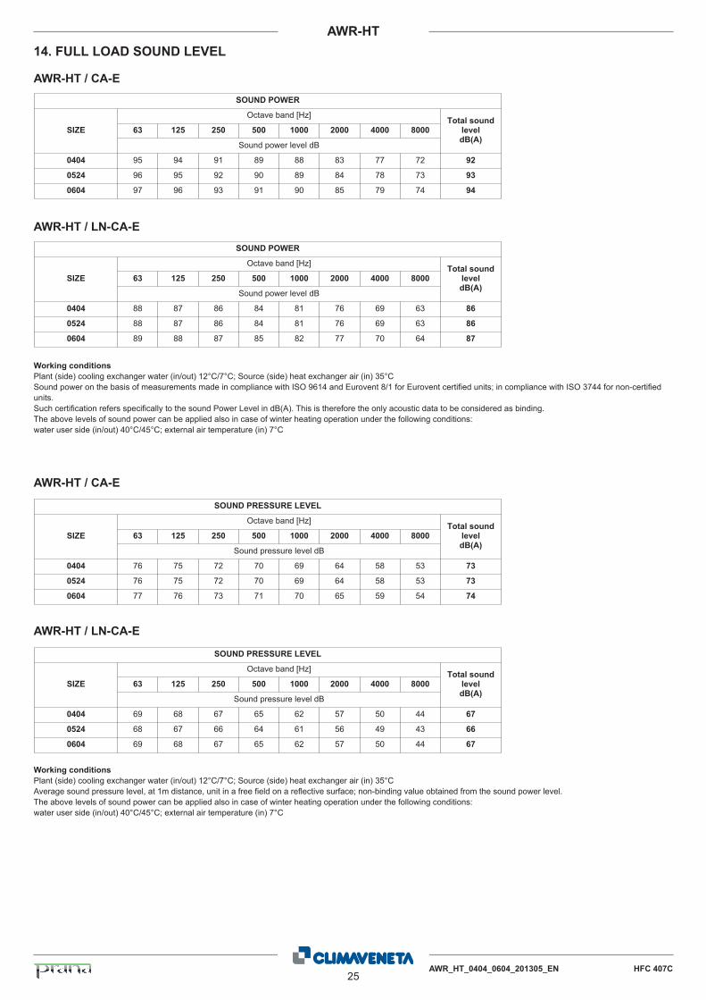
14. FULL LOAD SOUND LEVEL
SOUND POWER
Octave band [Hz]
63 125 250 500 1000 2000 4000 8000SIZETotal sound
leveldB(A)
Sound power level dB
0404 95 94 91 89 88 83 77 72 92
0524 96 95 92 90 89 84 78 73 93
0604 97 96 93 91 90 85 79 74 94
AWR-HT / CA-E
SOUND POWER
Octave band [Hz]
63 125 250 500 1000 2000 4000 8000SIZETotal sound
leveldB(A)
Sound power level dB
0404 88 87 86 84 81 76 69 63 86
0524 88 87 86 84 81 76 69 63 86
0604 89 88 87 85 82 77 70 64 87
AWR-HT / LN-CA-E
Working conditions
Plant (side) cooling exchanger water (in/out) 12°C/7°C; Source (side) heat exchanger air (in) 35°CSound power on the basis of measurements made in compliance with ISO 9614 and Eurovent 8/1 for Eurovent certified units; in compliance with ISO 3744 for non-certifiedunits.Such certification refers specifically to the sound Power Level in dB(A). This is therefore the only acoustic data to be considered as binding.The above levels of sound power can be applied also in case of winter heating operation under the following conditions:water user side (in/out) 40°C/45°C; external air temperature (in) 7°C
SOUND PRESSURE LEVEL
Octave band [Hz]
63 125 250 500 1000 2000 4000 8000SIZETotal sound
leveldB(A)
Sound pressure level dB
0404 76 75 72 70 69 64 58 53 73
0524 76 75 72 70 69 64 58 53 73
0604 77 76 73 71 70 65 59 54 74
AWR-HT / CA-E
SOUND PRESSURE LEVEL
Octave band [Hz]
63 125 250 500 1000 2000 4000 8000SIZETotal sound
leveldB(A)
Sound pressure level dB
0404 69 68 67 65 62 57 50 44 67
0524 68 67 66 64 61 56 49 43 66
0604 69 68 67 65 62 57 50 44 67
AWR-HT / LN-CA-E
Working conditions
Plant (side) cooling exchanger water (in/out) 12°C/7°C; Source (side) heat exchanger air (in) 35°CAverage sound pressure level, at 1m distance, unit in a free field on a reflective surface; non-binding value obtained from the sound power level.The above levels of sound power can be applied also in case of winter heating operation under the following conditions:water user side (in/out) 40°C/45°C; external air temperature (in) 7°C
26AWR_HT_0404_0604_201305_EN HFC 407C
AWR-HT
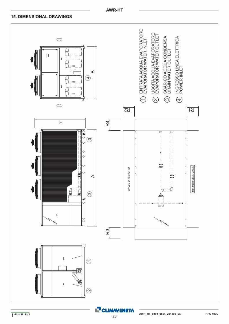
15. DIMENSIONAL DRAWINGS
R2
R3
R4
SPA
ZIO
DI R
ISP
ETT
O
MIN
IMU
M C
LEA
RA
NC
E
EN
TRAT
A A
CQ
UA
EVA
PO
RAT
OR
EE
VAP
OR
ATO
R W
ATE
R IN
LET
US
CIT
A A
CQ
UA
EVA
PO
RAT
OR
EE
VAP
OR
ATO
R W
ATE
R O
UTL
ET
SC
AR
ICO
AC
QU
A C
ON
DE
NS
AD
RA
IN W
ATE
R O
UTL
ET
ING
RE
SS
O L
INE
A E
LETT
RIC
A P
OW
ER
INLE
T
3 41 2
AB
R1
H
12
33
4
AWR_HT_0404_0604_201305_EN HFC 407C27
AWR-HT
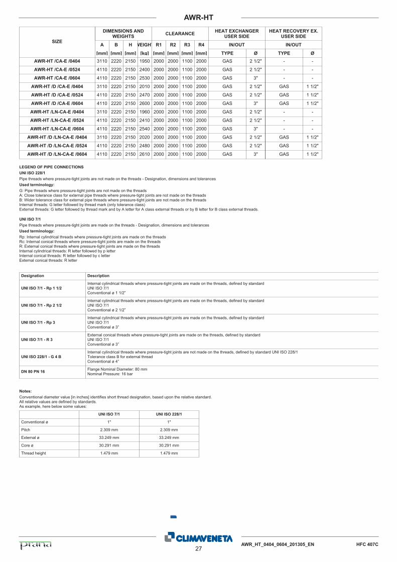
DIMENSIONS ANDWEIGHTS CLEARANCE HEAT EXCHANGER
USER SIDEHEAT RECOVERY EX.
USER SIDE
A B H WEIGHT R1 R2 R3 R4 IN/OUT IN/OUT
[mm] [mm] [mm] [kg] [mm] [mm] [mm] [mm] TYPE Ø TYPE Ø
SIZE
AWR-HT /CA-E /0404 3110 2220 2150 1950 2000 2000 1100 2000 GAS 2 1/2" - -
AWR-HT /CA-E /0524 4110 2220 2150 2400 2000 2000 1100 2000 GAS 2 1/2" - -
AWR-HT /CA-E /0604 4110 2220 2150 2530 2000 2000 1100 2000 GAS 3" - -
AWR-HT /D /CA-E /0404 3110 2220 2150 2010 2000 2000 1100 2000 GAS 2 1/2" GAS 1 1/2"
AWR-HT /D /CA-E /0524 4110 2220 2150 2470 2000 2000 1100 2000 GAS 2 1/2" GAS 1 1/2"
AWR-HT /D /CA-E /0604 4110 2220 2150 2600 2000 2000 1100 2000 GAS 3" GAS 1 1/2"
AWR-HT /LN-CA-E /0404 3110 2220 2150 1960 2000 2000 1100 2000 GAS 2 1/2" - -
AWR-HT /LN-CA-E /0524 4110 2220 2150 2410 2000 2000 1100 2000 GAS 2 1/2" - -
AWR-HT /LN-CA-E /0604 4110 2220 2150 2540 2000 2000 1100 2000 GAS 3" - -
AWR-HT /D /LN-CA-E /0404 3110 2220 2150 2020 2000 2000 1100 2000 GAS 2 1/2" GAS 1 1/2"
AWR-HT /D /LN-CA-E /0524 4110 2220 2150 2480 2000 2000 1100 2000 GAS 2 1/2" GAS 1 1/2"
AWR-HT /D /LN-CA-E /0604 4110 2220 2150 2610 2000 2000 1100 2000 GAS 3" GAS 1 1/2"
LEGEND OF PIPE CONNECTIONSUNI ISO 228/1Pipe threads where pressure-tight joints are not made on the threads - Designation, dimensions and tolerancesUsed terminology:G: Pipe threads where pressure-tight joints are not made on the threadsA: Close tolerance class for external pipe threads where pressure-tight joints are not made on the threadsB: Wider tolerance class for external pipe threads where pressure-tight joints are not made on the threadsInternal threads: G letter followed by thread mark (only tolerance class)External threads: G letter followed by thread mark and by A letter for A class external threads or by B letter for B class external threads.
UNI ISO 7/1Pipe threads where pressure-tight joints are made on the threads - Designation, dimensions and tolerancesUsed terminology:Rp: Internal cylindrical threads where pressure-tight joints are made on the threadsRc: Internal conical threads where pressure-tight joints are made on the threadsR: External conical threads where pressure-tight joints are made on the threadsInternal cylindrical threads: R letter followed by p letterInternal conical threads: R letter followed by c letterExternal conical threads: R letter
Designation Description
Internal cylindrical threads where pressure-tight joints are made on the threads, defined by standardUNI ISO 7/1Conventional ø 1 1/2”
UNI ISO 7/1 - Rp 1 1/2
Internal cylindrical threads where pressure-tight joints are made on the threads, defined by standardUNI ISO 7/1Conventional ø 2 1/2”
UNI ISO 7/1 - Rp 2 1/2
Internal cylindrical threads where pressure-tight joints are made on the threads, defined by standardUNI ISO 7/1Conventional ø 3”
UNI ISO 7/1 - Rp 3
External conical threads where pressure-tight joints are made on the threads, defined by standardUNI ISO 7/1Conventional ø 3”
UNI ISO 7/1 - R 3
Internal cylindrical threads where pressure-tight joints are not made on the threads, defined by standard UNI ISO 228/1Tolerance class B for external threadConventional ø 4”
UNI ISO 228/1 - G 4 B
Flange Nominal Diameter: 80 mmNominal Pressure: 16 barDN 80 PN 16
Notes:Conventional diameter value [in inches] identifies short thread designation, based upon the relative standard.All relative values are defined by standards.As example, here below some values:
UNI ISO 7/1 UNI ISO 228/1
Conventional ø 1" 1"
Pitch 2.309 mm 2.309 mm
External ø 33.249 mm 33.249 mm
Core ø 30.291 mm 30.291 mm
Thread height 1.479 mm 1.479 mm

Topqualität mit Spitzenservice
Grüezi, ich bin einer der über 40 Servicetechniker der CTA.
So sind sie, die «Botschafter» der CTA: freundlich und kom-petent. Immer da, wenn Sie sie brauchen. 24 Stunden, rund um die Uhr. Mit Servicestellen und über 40 Fahrzeugen in der ganzen Schweiz. Ein gutes Gefühl für die Kunden und für die Installateure, die sich in jedem Fall auf Unterstützung, Service und Support verlassen können.
Zu den Stärken in Planung, Produktion und Montage kom-men die Stärken in Service und Dienstleistungen, in Lager-haltung und Logistik, in Aus- und Weiterbildung. Sie sind es, die die CTA zu einem zuverlässigen Partner machen.
Aber CTA geht noch weiter: Mit wertvollen Zusatzleistungen wie zum Beispiel dem Support im Bereich der ChemRRV oder dem auf 12 Jahre angelegten Schutz- und Sicherheitsprogramm CTAplus für Wärmepumpen.
Solothurn
Münsingen
Kriens
Zürich
Buchs
Hauptsitz
Niederlassung
Geschäftsstellen
Servicestellen
Fribourg
Lausanne
BaselUzwil
Ce
rtified System
I S O 9 0 0 1
Ce
rtified System
I S O 1 4 0 0 1
www.cta.ch [email protected]
Freiburg CTA AGRoute André Piller 20 CH-1762 GivisiezTelefon +41 (0)26 475 55 90Fax +41 (0)26 475 55 91
Kriens CTA AG Grabenhofstrasse 6 CH-6010 KriensTelefon +41 (0)41 348 09 90 Fax +41 (0)41 348 09 95
Bern CTA AGHunzikenstrasse 2 CH-3110 MünsingenTelefon +41 (0)31 720 10 00Fax +41 (0)31 720 10 50
Uzwil CTA AGBahnhofstrasse 111 CH-9240 UzwilTelefon +41 (0)71 951 40 30Fax +41 (0)71 951 40 50
Solothurn CTA AGBernstrasse 1 CH-4573 Lohn-AmmannseggTelefon +41 (0)32 677 04 50Fax +41 (0)32 677 04 51
Zürich CTA AGAlbisriederstrasse 232 CH-8047 ZürichTelefon +41 (0)44 405 40 00 Fax +41 (0)44 405 40 50
Buchs CTA AGLangäulistrasse 35 CH-9470 BuchsTelefon +41 (0)81 740 36 40Fax +41 (0)81 740 36 41
Basel CTA AG Grabenackerstrasse 15 CH-4142 MünchensteinTelefon +41 (0)61 413 70 70 Fax +41 (0)61 413 70 79
Lausanne CTA AG En Budron B2 CH-1052 Le Mont s/LausanneTelefon +41 (0)21 654 99 00 Fax +41 (0)21 654 99 02
08.0
3.20
13/d
t Te
chni
sche
Änd
erun
gen
vorb
ehal
ten