Embed Size (px)
Citation preview

Agrident GmbH, Steinklippenstr. 11, D-30890 Barsing hausen
Phone +49 5105 582573-10 - Fax +49 5105 582573-17
AWR 100 Stickreader
F i r m w a r e 2 . 0 0 a n d h i g h e r
P C - D e m o s o f t w a r e 2 . 0 0 a n d h i g h e r
V10/02/10
10/02/10 Page 2 of 47
AWR100 Manual
© Copyright 2010 by Agrident GmbH Torsten Bade, Technical Support All rights reserved. No part of this publication may be reproduced, stored in a retrieval system, or transmitted, in any form or by any means, electronic, mechanical, photocopying, recording or otherwise, without prior written permission of Agrident GmbH. Agrident GmbH reserves the right to make changes to any and all parts of this documentation without obligation to notify any person or entity of such changes. February 2010 Agrident GmbH Steinklippenstr. 11 30890 Barsinghausen Germany Phone +49 (0) 51 05 582573-10 Fax +49 (0) 51 05 582573-17 E-Mail: [email protected] www.agrident.com
10/02/10 Page 3 of 47
AWR100 Manual
Content
1 Typical applications ............................................................................................. 5
2 Preparing for use ................................................................................................. 6
2.1 AWR signaling and interface ........................................................................ 7
2.2 Accessories .................................................................................................. 8
2.3 Installing or changing the battery pack ......................................................... 9
3 Trickle charging the battery pack....................................................................... 11
4 Battery pack fast charger .................................................................................. 12
5 Controlling the AWR .......................................................................................... 13
5.1 Switching on the AWR ............................................................................... 13
5.2 Reading transponders ................................................................................ 14
5.2.1 Reading transponders after the AWR is switched on .......................... 14
5.2.2 Reading transponders immediately ..................................................... 17
5.3 Reading range depending on the transponder orientation ......................... 17
5.4 Using the AWR menu................................................................................. 18
5.4.1 Next group........................................................................................... 19
5.4.2 Printer ................................................................................................. 19
5.4.3 Stored datasets ................................................................................... 19
5.4.4 Show last IDs ...................................................................................... 20
5.4.5 Date/Time ........................................................................................... 21
5.4.6 Online / offline mode .......................................................................... 21
5.4.7 Bluetooth ............................................................................................. 21
5.4.8 Start Inquiry ......................................................................................... 22
5.4.9 Custom config ..................................................................................... 23
5.4.10 Reset config ........................................................................................ 23
5.4.11 Clear datasets ..................................................................................... 24
5.5 High power mode ....................................................................................... 24
5.6 Permanent Read ........................................................................................ 24
5.7 Switch off time ............................................................................................ 25
5.8 Show Tag time ........................................................................................... 25
5.9 Battery management .................................................................................. 25
6 AWR100 Demo Software .................................................................................. 26
6.1 Installation .................................................................................................. 26
6.2 Comport settings ........................................................................................ 26
6.3 The file menu ............................................................................................. 27

10/02/10 Page 4 of 47
AWR100 Manual
6.4 The monitor window ................................................................................... 28
6.5 Diagnosis ................................................................................................... 28
6.6 Database .................................................................................................... 28
6.6.1 Database – Main ................................................................................. 29
6.6.2 Dataset – Amount of datasets ............................................................. 30
6.6.3 Database – Dataset ............................................................................ 30
6.6.4 Database – File ................................................................................... 30
6.6.5 Database – Separation ....................................................................... 31
6.7 Event Database .......................................................................................... 31
6.8 Received Tag ............................................................................................. 33
6.9 Configuration .............................................................................................. 33
6.9.1 Configuration – Reader ....................................................................... 35
6.9.1.1 Serial number - Firmware ................................................................ 35
6.9.1.2 Access level ..................................................................................... 35
6.9.1.3 Extra Settings - Timeouts ................................................................ 35
6.9.1.4 LCD – Second Display Line ............................................................. 36
6.9.1.5 LCD - Contrast ................................................................................. 37
6.9.1.6 LCD – Display Menu Language ....................................................... 37
6.9.2 Configuration – Operational ................................................................ 38
6.9.2.1 IO – Led and Beeper ....................................................................... 38
6.9.2.2 RF – Power Mode ............................................................................ 38
6.9.2.3 Check for double-reads ................................................................... 39
6.9.2.4 Permanent Read ............................................................................. 39
6.9.2.5 Wireless Synchronization ................................................................ 40
6.9.3 Configuration – Output Formats .......................................................... 42
6.9.4 Configuration – Bluetooth ................................................................... 43
6.9.5 Configuration – Printer ........................................................................ 44
6.9.6 Configuration – Real Time Clock ........................................................ 45
6.9.7 Configuration – Memory ...................................................................... 45
7 Safety and care ................................................................................................. 46
8 Warranty ............................................................................................................ 46
9 FCC digital device limitations ............................................................................ 47
10 CE MARKING ................................................................................................ 47
11. Trouble shooting ............................................................................................ 47
10/02/10 Page 5 of 47
AWR100 Manual
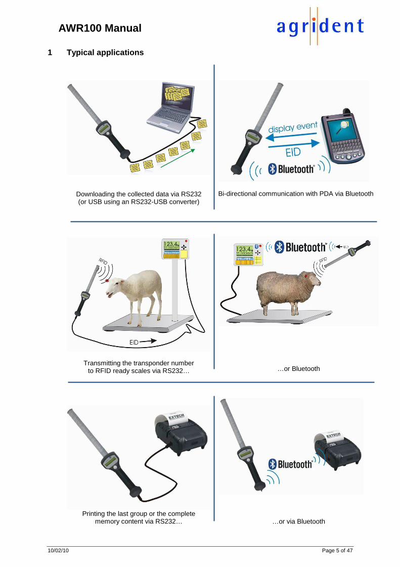
1 Typical applications
Downloading the collected data via RS232 (or USB using an RS232-USB converter)
Bi-directional communication with PDA via Bluetooth
Transmitting the transponder number to RFID ready scales via RS232…
…or Bluetooth
Printing the last group or the complete
memory content via RS232…
…or via Bluetooth

10/02/10 Page 6 of 47
AWR100 Manual
2 Preparing for use
Figure 1: AWR100 Stickreader
The AWR100 Stickreader is shipped with one rechargeable battery pack, one RS232 end cap plus RS232 cable (1,5m), one power supply for trickle charging and a CD containing all manuals and AWR100 demo software. Before starting to work with the reader, it is recommended to charge the battery pack completely. This can be done by using the power supply for trickle charging (takes up to 20 hours) or the external fast-charging station (please see chapters 2 and 3 for details).
When charging for the first time after long-term storage, the battery capacity might be decreased. Restore such batteries to original performance by repeating several cycles of charging and discharging. When storing batteries for more than 1 year, charge after 6 month to prevent leakage and deterioration in performance due to self- discharging.
antenna
RS232 cable battery pack
button
handle grip
beeper
display
blue LED
end cap with RS232 and power interface
red and green LED
protection cap
hand strap

10/02/10 Page 7 of 47
AWR100 Manual
2.1 AWR signaling and interface
Parameter
Setting
Red LED
The red LED is flashing while the AWR tries to read transponders. This feature can be disabled or enabled with AWR demo software.
Green LED
The Green LED is flashing after a transponder was read. This feature can be disabled or enabled with AWR demo software.
Beeper
The Beeper sounds, after a transponder was read. This option can be changed using the AWR demo software.
Blue LED
The blue LED is used for several events (e.g. transponder was read, low battery warning).
Display
The LCD displays all necessary information (e.g. number of read transponder, ready to work, menu items).
Read button
� is switching the reader on. � starts reading. � enters the menu by double pressing, if the AWR
is switched on � moves to the next menu item by a short press � confirms selections in the menu by a long press
Cable connector
� Interface for transferring data between AWR and
other devices � Trickle charging the battery via RS232 cable

10/02/10 Page 8 of 47
AWR100 Manual
2.2 Accessories
� Bluetooth end cap � External fast-charging station � Rechargeable battery pack � RS232 end cap � RS232 cable (1.5m) � Cigarette lighter cable (12V, for trickle charging only)
Figure 2: Accessories
Figure 3: External fast charging station
The power supply can vary country-specific.
end cap with RS232 and power interface AEC100
rechargeable battery pack ARB100
Bluetooth end cap ABE100
RS232 cable AIC115
cigarette lighter charging cable AAC100

10/02/10 Page 9 of 47
AWR100 Manual
2.3 Installing or changing the battery pack
If the Stick Reader is used for the first time, the battery pack has to be installed.
Turn the screw of the end cap anti clockwise.
Remove the end cap.
Remove the old battery pack.

10/02/10 Page 10 of 47
AWR100 Manual
Install the new battery pack.
Attach the end cap to the reader and turn the screw of the end cap clockwise.
The screw has to be fastened completely, otherwise contact problems can occur! Additionally the seal in the end cap is not functioning properly in that case and the AWR might not be watertight (IP67) anymore. Water damages due to the improper attachment of the end cap are not covered by the warranty!

10/02/10 Page 11 of 47
AWR100 Manual
3 Trickle charging the battery pack
Trickle charging can take up to 20 hours, depending on the remaining battery capacity. Longer charging is always allowed and does not damage the reader or the battery.
Connect the RS232 cable to the RS232 end cap.
Plug in the RS232 connector into the jack of the RS232 end cap and turn the connector clockwise. From the point, where the green indicator ring appears, the connection of the plug is correct and IP67.

10/02/10 Page 12 of 47
AWR100 Manual
Connect the power jack of the RS232 cable to the power supply for trickle charging. Also connect the power supply to the mains using the power cord.
Figure 4: Connections and accessories for trickle charging
The power cord can vary country-specific.
4 Battery pack fast charger
For faster battery charging, an external charging station is available.
Figure 5: Battery pack fast charger, the power supply can vary country-specific.
power supply for trickle charging
RS232 cable
RS232 end cap (attached to AWR)
power cord

10/02/10 Page 13 of 47
AWR100 Manual
Figure 6: Battery pack fast charger with battery pack inserted
5 Controlling the AWR
5.1 Switching on the AWR
In the off state, most parts of the electronic is separated from the battery. Only a few parts (e.g. the internal Real Time Clock) are supplied with power. Nothing is displayed on the LCD in that case. In order to activate the AWR, the button must be pressed for a short time. “Press key” appears on the first display line and a battery symbol on the right side indicates the approximate remaining battery capacity.
Figure 7: Activate the AWR by pressing the read button
battery symbol

10/02/10 Page 14 of 47
AWR100 Manual
After the AWR is ready to work, the following text appears on the display:
Press key
If no action happens, the AWR will power down after a certain time. This time is configurable from 5 seconds to 600 seconds, the default value is 10 seconds. If Bluetooth is activated and connected, a Bluetooth symbol appears on the right side of the second line of the display:
Press key
If a Bluetooth end cap is attached, the Bluetooth module is initialized after switching on. It can take a few seconds until the Bluetooth connection is established. Nevertheless the reader can start working and is able to read tags, the connection is made in the background. The reader remembers the IDs of the tags, which were read after switching on. As soon as the Bluetooth connection is established, the AWR will send all these IDs to the Bluetooth interface in case that the Online mode is activated.
5.2 Reading transponders
5.2.1 Reading transponders after the AWR is switche d on
Wait until
Press key
appears on the display. Press the button until
Read tag .
appears on the LCD. Now release the button. The AWR starts to read transponders for a certain time, which is also configurable (see chapter 6.9.1.3 “Extra Settings - Timeouts”). The reading procedure is signaled by a red flashing LED. Furthermore a progress bar appears in the second line of the display. The flashing of the red LED can enabled and disabled with the configuration software.

10/02/10 Page 15 of 47
AWR100 Manual
Figure 8: Reading Transponders

10/02/10 Page 16 of 47
AWR100 Manual
If no transponder has been read, the following message appears on the first line of the LCD:
No Transponder
While displaying this message, the backlight of the display is on. If a transponder has been read, the reading procedure is aborted immediately. A successful reading is signaled by a green flashing LED at the top of the AWR, a flashing blue LED above the display, and the beeper. The green LED and the beeper can be enabled and disabled using the demosoftware. In the first line of the LCD, the transponder number is displayed in decimal format. The second line is used to show the reading time and the transponder type, where “F” stands for FDX-B and “H” means HDX.
984 010900316360 F 12:41:26
The information in the second line can be changed for displaying an animal counter or the advanced ISO information of the transponder. Please see chapter 6.9.1.4 for further information. The maximum time in which this information is displayed, is configurable as well (Show Tag Time). This time can be configured from 1 second to 60 seconds, the default value is 5. For further information please see chapter 6.9.1.3) If an event is assigned to the read transponder via an external database, the corresponding string will be displayed in the second line of the LCD:
Selection Press Key
The maximum time in which the event string is displayed, is also configured via the “Show Tag Time”. Pressing the button will exit this screen before the time has elapsed. Chapter 6.7 explains the event-feature more detailed.
If no event is assigned to this transponder, the ID will be displayed according to the configured time. After this time, or if the button was pressed before, the start screen appears again:
Press key

10/02/10 Page 17 of 47
AWR100 Manual
5.2.2 Reading transponders immediately
If the AWR is switched off, press the button until
Read tag .
appears on the display. The reading procedure is the same as explained in chapter 5.2.1.
5.3 Reading range depending on the transponder orie ntation
Ferrite antennas have the following characteristics of flux lines:
Figure 9: Flux lines Thus the following best reading orientation for transponders is:
Figure 10: Best reading orientation

10/02/10 Page 18 of 47
AWR100 Manual
Accordingly there are is also a worst reading orientation:
Figure 11: Worst reading orientation
5.4 Using the AWR menu
After the message Press key
appears on the display, the menu of the reader can be entered by double pressing the button. With a short-press you can move to the next menu item. A long-press enters a submenu or confirms a selection within the corresponding menu. If the button is not pressed within 3 seconds, the menu will be left auto-matically.
The AWR menu has the following structure:
Menu item Complete Access
Medium Access Read only
Next group Printer * *
Stored datasets Show last IDs Date / Time Online mode Bluetooth on ** Start Inquiry **
Custom config *** *** Reset config
Clear datasets **** **** * only available if the printer option is enabled, default = disabled ** only visible if a Bluetooth end cap is attached to the AWR *** only available if a custom configuration has been set via the demosoftware first **** the checkbox “Clear Datasets” needs to be activated in addition to the Access level

10/02/10 Page 19 of 47
AWR100 Manual
The menu access level can be set via the AWR demosoftware (see chapter 6.9.1.2). The “Complete Access” level (factory default) shows all menu items, as far as available. If, for example, no Bluetooth end cap is attached to the reader, the Bluetooth options will not be displayed. The “Medium Access” level allows to enter the menu and to access all features, which do not change the configuration (except custom configuration). In these two modes it is possible, to activate the additional option “Clear datasets”.
Please exercise extreme caution with the “Clear datasets” option! This menu item allows to clear the complete memory content and thus important data might get lost irreversibly!
The “Read only” setting ensures that the menu cannot be accessed at all.
5.4.1 Next group
The “Next group” option allows to insert separators between the collected IDs and thus to divide the read transponders into groups. This is a helpful feature if, for example, the data are collected on different farms or the animals are sold to different places.
Agrident V2.00 ->Next group
Perform a long press in order to insert a new group. After the group was created successfully, you will see the following confirmation:
Agrident V2.00 Done
In addition the blue LED is switched on for appr. 1 second.
5.4.2 Printer
The printer menu is only visible, if the printer option is enabled, per factory default it is disabled. You can change this setting using the AWR demo-software. For further details about the printer option, please see the separate manual “AWR_printer_option”.
5.4.3 Stored datasets
The next menu item shows the number of stored datasets:
Stored datasets 5/ 138/5000

10/02/10 Page 20 of 47
AWR100 Manual
The first number shows the animal counter of the current group, in this example 5. The second number represents the sum of all stored datasets including group separators (in this example 138). The last number represents the amount of datasets which can be stored on the AWR (5000).
The readers memory allows to store 5000 datasets. If 5000 transponders and separators were stored, the datasets must be cleared before new transponders can be read.
In case that 5000 datasets are already stored and a new transponder is read, the following information appears on the LCD display:
Database out of memory
5.4.4 Show last IDs
This item allows you to review the complete memory content of the AWR.
Agrident V2.00 -> Show last IDs
Make a long-press while “Show last IDs” is displayed.
984 010900316360 G05#033 12:41:26
The first line of the displays shows the ID, the second line the group, in which the ID is saved (here: group 5), the consecutive number of the dataset in the current group (here: 33) and the timestamp of the transponder. The AWR starts with the latest read ID and then goes through the memory backwards. Perform a short press in order to move to the previous dataset, perform a long press in order to move to the previous group. If the last transponder in the group has been displayed, the reader will automatically move to the previous group after a short-press:
Previous group Group 0004
If you scrolled through the complete content of the memory, the display will show:
Agrident V2.00 No IDs available

10/02/10 Page 21 of 47
AWR100 Manual
5.4.5 Date/Time
The second line of the display shows the current setting of the integrated Real Time Clock:
Agrident V2.00 11.01.10 12:30
If date and time are incorrect, the Real Time Clock has to be synchronized using the AWR demosoftware or your corresponding management software.
5.4.6 Online / offline mode
In the Online mode the transponder data are transmitted to the interface (RS232 or Bluetooth) immediately after the tag was read. Additionally the data are stored in the internal memory of the reader. The Offline mode disables the immediate transmission, the data are only stored in the database of the AWR. Per factory default the AWR is set to Online mode:
Agrident V2.00 ->Online mode
In order to set the reader into the Offline mode, make a long press at his point. After the setting was changed, the display shows:
Agrident V2.00 ->Offline mode
5.4.7 Bluetooth
The Bluetooth options are only available, if a Bluetooth end cap is attached to the AWR. In the following menu item Bluetooth can be disabled or enabled.
Agrident V2.00 ->Bluetooth on
Perform a long-press in order to deactivate Bluetooth. This can make sense for saving battery power, if you do not want to use the Online mode and the stored datasets will be read out later in the office.
Agrident V2.00 ->Bluetooth off
If the key is pressed approximately 2 seconds again, the Bluetooth interface will be reactivated.

10/02/10 Page 22 of 47
AWR100 Manual
5.4.8 Start Inquiry
This menu offers an easy way of pairing the readers Bluetooth module with another Bluetooth device. The other device can be a PC, a PDA or a Bluetooth enabled scale. The advantage of this method is, that you do not need to know the address of the opposite module and you do not need a PC for pairing.
Agrident V2.00 ->Start Inquiry
A long-press starts the scan for other Bluetooth devices (Inquiry).
Drop connection
appr. 3 seconds
Scan for devices .....
appr. 15 seconds
1/3 device Agrident PDA
The first line of the display shows the number of the discovered device and how many devices have been found (in this case 3). The second line displays the name of the current device, here: “Agrident PDA”. Do a long-press for pairing the AWR with the displayed device. If the pairing procedure was successful, the AWR will display
Peer adr saved Adr=0015832A2938
where the second line shows the “BD-address” of the other device (Bluetooth slave). In this case, the AWR is the Bluetooth master and controls the connection.
Press the button for a short time in order move to the next discovered device, for example:
2/3 device Agrident PC
If you have moved through the list of devices, you have the option to leave the list without any action:
-> Leave
Devicelist
long-press = leave device-list

10/02/10 Page 23 of 47
AWR100 Manual
It is also possible to assign the address of the other Bluetooth device using the AWR demosoftware. The reader can also be configured to be the Bluetooth slave, which is not recommended unless there is a customized software which is able to control the connection in an “intelligent” way. For further details please see the “AWR100_Bluetooth_manual”, which is on the delivered AWR CD.
5.4.9 Custom config
This menu item allows to reset the AWR to customized settings. These settings have to be applied as custom settings using the AWR demosoftware first. The demosoftware allows to save modified reader settings in a file. Once these changed settings are applied to the AWR as custom settings, the reader can be reset to these settings via the menu, without the need for connecting to a PC:
Agrident V2.00 ->Custom config
Confirm your choice with a long-press:
Agrident V2.00 Reset config...
Agrident V2.00 Done
A short press moves to the next menu item. If the button is not pressed for 3 seconds at all, the menu will be left automatically.
5.4.10 Reset config
The “Reset config” submenu will reset the AWR to factory default settings:
Agrident V2.00 ->Reset config
Confirm your choice with a long-press:
Agrident V2.00 Reset config...
Agrident V2.00 Done

10/02/10 Page 24 of 47
AWR100 Manual
5.4.11 Clear datasets
If the corresponding setting is activated via the demosoftware, the last menu item in the AWRs menu is “Clear datasets”. It allows to clear the complete memory content without being connect to a PC:
Agrident V2.00 ->Clear datasets
Confirm with a long press. Because of the high risk of deleting data accidentally, the AWR will ask for another confirmation:
Clear all data? Long press = Yes
If the choice is confirmed again with another long-press, the AWR will delete the collected data and empty the memory:
Clear dataset 4993-5000
5.5 High power mode
If the reading range is to small for the application, the high power mode can be activated via configuration software (chapter 6.9.2.2). In high power mode the reading range increases, but the power consumption as well. That means a shorter operation time for the battery. If high power mode is selected, the string “HP” is displayed additionally to “Read tag”. The factory default setting is “Low power”.
Read tag HP .
The high power mode increases the reading range for HDX transponders up to 20 percent compared to low power. For FDX transponders it is less. The power consumption in high power mode is about three times higher, than in low power mode!
5.6 Permanent Read
For applications, where lots of transponders have to be read within a short time, the AWR offers a permanent read mode. In that mode the reader is activating the reading function for a longer time, independently of a successful reading. The permanent read mode can be activated in the AWR demosoftware, the settings can be changed there as well (please see chapter 6.9.2.4 – „Permanent Read“). Permanent read is deactivated per factory default.

10/02/10 Page 25 of 47
AWR100 Manual
5.7 Switch off time
The AWR is switched off after a certain time automatically, if no action has taken place (e.g. transponder reading or menu access). The switch off time is configurable between 5 and 600 seconds with the configuration software (see chapter 6.9.1.3 – “Extra Settings - Timeouts”). The default time is 10 seconds.
5.8 Show Tag time
The time for displaying the ID of a read tag (or for displaying events) can be configured between 1 and 60 seconds. This setting is called “Show Tag Time”, the default value is 5. Show Tag Time
984 010900316360 F 12:41:26
Press key
5.9 Battery management
Symbol Meaning solid The battery is charged completely � 100 % solid Battery capacity is appr. 80 % solid Battery capacity is appr. 60 % solid Battery capacity is appr. 40 % solid Battery capacity is appr. 20 % solid Battery capacity is appr. 10 % blinking Battery is down to appr. 5 %
The blinking symbol indicates that the battery should be replaced or recharged soon. If the AWR detects a too low voltage, the following information appears on the LCD display:
Low battery
After displaying the information the Stick Reader is switched off automatically. The AWR offers internal trickle charging. A complete charging cycle can take up to 20 hours (longer charging time is allowed). For rapid charging, an external battery charger is available. For the normal operation and internal trickle charging, only the delivered 12V power supply has to be used. If the voltage of the used power supply is too high, the following information appears on the display directly after power on:
Warning High voltage!
After displaying this information, the reader is switched off automatically.

10/02/10 Page 26 of 47
AWR100 Manual
6 AWR100 Demo Software
The AWR demosoftware is a configuration tool, which is supplied with every reader for free. With this software you can apply all possible settings to the AWR and demonstrate all reader features. AWR demo is for configuration and demonstration purposes only, it does not offer any management possibilities!
6.1 Installation
Please start “setup.exe”, select your language for the installation and follow the instructions of the setup assistant.
6.2 Comport settings
After the first start of the program, the correct comport has to be selected. Therefore choose “Comport” in the menu Settings:
The following dialog appears:
Select the correct Comport and press OK. If the AWR is not connected, the following status message is displayed at the bottom of the main window:
In this case press “Connect” if the Comport is chosen correctly.
Selected Comport

10/02/10 Page 27 of 47
AWR100 Manual
After pressing “Connect”, the demosoftware tries to communicate with the AWR, which is indicated by an orange status symbol. The “Connect” button changed its text to “Disconnect”:
If the reader was detected successfully, the color of the connection status symbol will turn into green:
6.3 The file menu
The file menu is mainly used for leaving the software, setting the comport and for opening additional windows:
...exits the demosoftware, you might also use
...opens the Comport-menu
...opens the Monitor window ...opens the Diagnosis window
...opens the Database window for downloading and saving data ...opens the Event-Database window
...information about the demosoftware version

10/02/10 Page 28 of 47
AWR100 Manual
6.4 The monitor window
The monitor window shows the serial communication from the PC to the AWR and back. It is more intended to be used by software developers than by end customers.
Since this manual is written for end users, the monitor is not explained any further here. The AWR protocol description explains the monitor window in detail.
6.5 Diagnosis
This window offers the possibility, to sample the receiver signals of the reader. The use of this feature requires deeper knowledge of RFID and thus it will not be explained in this manual.
6.6 Database
The AWR has an internal memory, in which up to 5000 transponder datasets can be stored. In order to download collected data or to clear the memory, choose “Database” in the file menu “Database”.

10/02/10 Page 29 of 47
AWR100 Manual
The following dialog appears:
6.6.1 Database – Main
With the button “Get all” the download sequence will be started. The demo-software will readout the complete memory content and all saved IDs will be displayed in the database window.
Before the collected data are being downloaded, the demosoftware will open a file dialog which allows to save the data in a txt-file. Choose a location and a filename if you want to save the data. Press “Save” in order to confirm. If you don´t want to save the data, press “Cancel”. In this case, the datasets will just be downloaded and displayed – not saved.
Shows the downloaded data after “Get all” was pressed or a previously downloaded (and saved) list was opened

10/02/10 Page 30 of 47
AWR100 Manual
The download options “Block” or “Single” decide about the way of downloading the data. If “Block” is selected, there is only one command for reading the complete database. “Single” will request every dataset separately. This option is more interesting for software developers and not for end users. The default option is block, which is also the faster way of downloading. The pushbutton “Clear all” will empty the readers memory. All collected data will be deleted!
6.6.2 Dataset – Amount of datasets
In order to request the amount of saved datasets from the reader, press “get”. In this case 83 IDs are saved in the AWRs memory.
6.6.3 Database – Dataset
With “Get” the current dataset will be requested and displayed. Via the up/down arrows in the “Number” box, the next/previous dataset is requested. Another possibility to request a particular dataset is to enter the number of the dataset to be requested into the “Number” box and to confirm by pressing “Get”.
6.6.4 Database – File
Load: opens a file dialog for opening a previously saved download Save: opens a file dialog for saving downloaded data New file on new group: automatically creates a new file if a group separator was
detected in the downloaded data

10/02/10 Page 31 of 47
AWR100 Manual
6.6.5 Database – Separation
The default text for a group separator is “Group”. For the first group, the demo-software will insert “Group 1”.
If another separator is downloaded, the string “Group 2” will be inserted. This string might be changed into another text, e.g. “Farm” or “Pen”.
6.7 Event Database
The AWR offers the feature of bi-directional communication. If the online mode is activated, the reader sends the ID of the read transponder directly to the interface, either RS232 or Bluetooth. If the reader is connected to a host (PC or PDA), the incoming ID can be compared with existing IDs in a database. If the database contains an assignment for the incoming ID, it is possible to send an event string (maximum 16 ASCII characters) to the AWR. The command back to the AWR for displaying a string also contains the ID. If no new ID was read meanwhile, the AWR will display the corresponding string, e.g. “Sale”. In order to use this feature, your management software has to support it. The “Event Database” in the AWR demosoftware simulates such a database and thus allows to test this option. The Event Database window is opened by choosing “Eventdatabase” in the Database file-menu:

10/02/10 Page 32 of 47
AWR100 Manual
The “Event Database” window opens. In order to create a new assignment, you have to read a transponder first. Make sure that the Online-mode is activated, otherwise the ID won´t be sent via the interface.
The 12 digit ID appears in the “ID” field. Click into the “Event” textbox and enter the desired string. Press “Assign” in order to confirm.
The assignment will be displayed in the “Event Database” list-box. Press “Show” in order to display the string on the AWRs LCD:
Sale Press key
You might assign more transponders if you want. Just read another - not assigned - tag and proceed as described above. The main window contains a status section which also informs you about the activation state of the Event Database. Per default it is activated:
In order to disable the Event Database, press “Deactivate” in the Event-Database window:
The status will change in the main window:

10/02/10 Page 33 of 47
AWR100 Manual
“Remove” deletes assignments, “Sort” will change the order according to the ID.
6.8 Received Tag
The main window also contains a section “Received Tag”. If the Online-mode is activated, this area will display the last read transponder ID.
� Country or manufacturer code
� 12 digit ID
� Transponder type (FDX-B or HDX) *
� Event (if existing and Event Database
activated) * … only if the selected output format contains information about tag type The text-fields light up green for a short time, if a transponder was received:
6.9 Configuration
In order to change the reader settings, the configuration window has to be opened:
This is only possible, if the AWR is connected via the correct comport. As the configuration window opens, all current reader settings are read out and displayed in the corresponding fields.

10/02/10 Page 34 of 47
AWR100 Manual
The configuration window opens:
The following part of the configuration window is visible in all tabs:
…will readout the complete configuration in one step
…sets the complete configuration in one step
…resets the AWR to factory default settings
…opens a previously saved configuration file
…saves the displayed configuration to a file
…sets the displayed configuration as custom config
…resets the AWR to declared custom configuration
…informs about the success of an action
…indicates the progress of the running action
“Read all” and “Apply all” influence the settings in all tabs, not only options of the currently selected tab. Thus it also allows to apply customized settings – loaded from a configuration file – to new readers in only one step.

10/02/10 Page 35 of 47
AWR100 Manual
6.9.1 Configuration – Reader
The configuration window consist of several tabs, the first is “Reader”. Here you can configure general settings like “Access level”, timeouts, the display language, etc.
6.9.1.1 Serial number - Firmware
“Ser.” requests the serial number of the AWR
“Version” returns the AWR firmware version
6.9.1.2 Access level
The “Access level” configures the accessibility of particular menu items in the AWRs menu. “Read only” blocks the menu completely, “Medium Access” allows menu items, which do not change the configuration and “Complete Access” shows all available menu items. “Clear Datasets” can be enabled in medium and complete access additionally. For details about the access level, see chapter 5.4.
6.9.1.3 Extra Settings - Timeouts
Extra Settings Meaning Switch off Time
The Reader is switched off automatically if no action has taken place (e.g. transponder read or menu access). The switch off time is configurable between 5 and 600 seconds. Type in the desired value in seconds into the corresponding field and press “Set”.
The current setting can be requested by pressing the “get” button. In this example the switch off time is set to 10 seconds, which is also the default value.
Timeout
The “Timeout” in milliseconds decides about the maximum time, the transmitter is activated, respectively the AWR is trying to read transponder in. The default value is 5000.

10/02/10 Page 36 of 47
AWR100 Manual
Extra Settings Meaning Show Tag Time
The “Show Tag Time” determines the maximum time, a read tag is displayed in. Pressing the AWRs button again or reading another transponder will abort the display event earlier, of course. Please ensure that the “Switch off Time” is always configured longer than the Show Tag Time, otherwise the AWR will switch off before the Show Tag Time has elapsed. The default value is 5 seconds.
LCD
The LCD group-box is divided into three sections: “Second Display Line”, “LCD Contrast” and “AWR menu language”. All these settings influence the behavior of the readers display. The “get” button will request all settings in this box.
6.9.1.4 LCD – Second Display Line
This setting decides about the information which is displayed in the second line of the LCD, after a transponder has been read. Per factory default the timestamp will be displayed.
Display animal counter Display timestamp Display tag info
984 010900316360 ID Counter 28
984 010900316360 F 12:41:26
984 010900316360 1 0 00 00 0
In order to allow the ID counter to work properly, the AWR has to check for double-reads. If the animal counter is selected, the reader will automatically set “Check double-reads” to 100.
The “F” on the left side of the second display line indicates, that the read tag was an FDX-B type. Accordingly the AWR will display “H” in case of a read HDX tag. Additionally the time of reading is displayed.
Using this setting the AWR will show the advanced ISO information in the second LCD line. 1. Animal Flag 2. Retagging Counter 3. Species Code 4. Reserved Fields 5. Trailer Bit

10/02/10 Page 37 of 47
AWR100 Manual
If the animal counter was used and the AWR should be configured for displaying the timestamp or the advanced ISO information, the demosoftware will ask, if “Check for double-reads” should be deactivated as well.
Press “Yes” in order to deactivate the check for double-reads, press “No” in order to keep the check.
6.9.1.5 LCD - Contrast
Set contrast
Set contrast
6.9.1.6 LCD – Display Menu Language
The AWR supports different display languages. In order to change the language, the demosoftware has to be used. Press “set” in order to select your desired language.
An additional window opens, select the language you want to upload using the drop-down list and start the upload by clicking the button “set language”. At the moment English (default), Dutch, French, German, Italian and Spanish language files are included.
A progress bar indicates the status of the update, the AWR displays:
Update device...
The info-box shows the result:

10/02/10 Page 38 of 47
AWR100 Manual
The “Open File” button allows to add new language files. Language files have the file extension “lng” and might be edited with a simple text editor. If you want to change particular strings, please pay attention on the length of the strings. The demosoftware will check every translated string for errors (illegal characters or too long strings) and will refuse to upload languages which contain errors. In case of a detected error, the demosoftware will open a message-box:
In this case String1 contained an error. AWR demo will set the language back to English. Please check your translations and try again.
6.9.2 Configuration – Operational
This tab contains settings like RF-power mode, Permanent read and Wireless Synchronization.
6.9.2.1 IO – Led and Beeper While the RF field is activated, the red LED at the top of the reader is flashing. After a successful read, the green LED in front of the Stick Reader is activated and the beeper sounds.
This section allows to enable or disable the LEDs at the top of the AWR and the beeper. Press “get” in order to see the current settings or “set” in order to apply changes.
6.9.2.2 RF – Power Mode
In order to choose the power mode, select one of the radio buttons and press the corresponding “set” pushbutton, “get” will request the currently selected setting.
Please see also chapter 5.5 for details regarding the High Power Mode.

10/02/10 Page 39 of 47
AWR100 Manual
6.9.2.3 Check for double-reads The AWR can check its database for double-reads. Transponders, which were already read within the selected range, are not stored in the database again and they won´t be sent to the interface. The range to check can be set from 0 up to 5000, where 5000 is the maximum number of datasets. If a value of 0 is selected, the reader will not scan for double-reads. The default setting is “0”.
In order to set the range for checking double-reads, enter the desired value and press the “set” button. By clicking “get”, the current value is requested.
Because of the serial readout of the data from the memory, it can take a few seconds to scan for double-reads if the memory is almost full and a too high value is chosen.
During the scan for double-reads, the following message appears on the display:
Scan for Double reads
If the AWR detected a double-read within the selected range of datasets, the reader will display the transponder number in the first line of the LCD and the string “Double read” in the second line.
984 010900316360 Double read
6.9.2.4 Permanent Read If lots of transponders have to be read within a short time, the AWRs Permanent Read mode is an useful feature. If this mode is activated, the readers button will initiate continuous reading, whereby continuous means: until the Timeout has elapsed. The timeout has to be chosen in minutes, the default is one minute. In case of reading a transponder, the counter for the timeout will be restarted.

10/02/10 Page 40 of 47
AWR100 Manual
select the desired timeout using the up/down arrows, in this case 5 minutes are selected
In order to apply the settings, please mark the checkbox “Active” and confirm by clicking “set”. The current setting can be requested with “get”.
The reading speed for Permanent Read mode might also be adjusted. The reading speed decides about the number of reading attempts per second. If the slide-control is set to fast, you have the maximum possible number of reading attempts, but also the highest power consumption and thus a shorter battery operating time.
Move the slide-control to the left in order to slow down the reading speed or to the right for faster reading. Press “set” in order to confirm the change.
In the “Fast” setting the AWR will not insert any breaks between the reading attempts and thus the power consumption is higher. The slowest setting inserts a break of 500 milliseconds after 5 reading attempts. It can take slightly longer until the tag was read, but the battery operation time in “slow permanent read” mode is more than doubled compared to the fast setting. The slide control allows to choose 10 different settings, where the interval for the breaks is adjusted in 50 milliseconds steps in each case. The checkbox “Advanced” allows to modify these settings even more detailed. Please see the additional document “AWR_Permanent_Read_Mode” for further explanations.
6.9.2.5 Wireless Synchronization If multiple ISO11784/11785 readers are working in close proximity, they interfere which each other, if they are not synchronized. As a result, the reading distance is reduced, which is particularly a problem for Half-Duplex. Stationary readers are normally synchronized via cable. Since this is not possible for portable readers, there has to be another way in order to solve that problem: Wireless Synchronization (“Wireless Sync.”). If Wireless Sync. is activated, the reader can detect the presence of other readers and tries to adapt its timing to the timing of the others. Therefore the AWR needs to know the so called “Sync. level”. This Sync. level is a threshold which helps the reader to find out the point, where other readers activate their RF-field.

10/02/10 Page 41 of 47
AWR100 Manual
The recommended Sync. level is 2.00V. Per factory default Wireless Sync. is not activated.
In order to activated Wireless Sync., select the desired value using the up/down arrows and confirm with “set”.
For deactivating Wireless Sync. you can decrease the level until the textbox shows “off” and then press “set”, or you just click the button “set Off”, which is the faster way.
Wireless Sync. works better, if the other readers are not working with variable timing. That means, they should use a fixed timing with HDX listening periods of 20 milliseconds only.
It is highly recommended, to use the default level of 2.00V, if Wireless Sync. is activated. Choosing the value too low or too high might decrease the reading performance.
For further information regarding Wireless Sync., please contact your Agrident dealer.

10/02/10 Page 42 of 47
AWR100 Manual
6.9.3 Configuration – Output Formats
The AWR offers a lot of different output formats for optimal adaptation to the application and to the customers needs. The output format can be configured using the “Output Format” tab in the configuration window of the demosoftware.
Choose the desired output format and press “set” in order to send the setting to the reader. The “get” button requests the currently chosen format.
This output format does not apply to the format, the data are being downloaded from the internal memory! It just decides about the format which is used, to send the ID to the interface directly after reading!
In the default output format “Short ASCII 15”, the ID is transmitted as follows: 980123456789012 <CR> <LF> New line 12-digit ID 3-digit manufacturer or country code This format is accepted by most scales on the market and outputs the ID without any additional information or control characters. Other formats offer more information, e.g. the timestamp, the advanced ISO information, different initial characters up to the transponder raw data and a transmission frame for higher safety regarding fault-free transmission. For details about all the output formats, please see the separate manual “AWR_ Output_Formats”.

10/02/10 Page 43 of 47
AWR100 Manual
6.9.4 Configuration – Bluetooth
With the optional Bluetooth interface, the AWR is able to communicate with other devices wireless using Bluetooth technology. The index “Bluetooth” allows to change the corresponding settings and to pair devices.
Enable or disable Bluetooth Decides if the AWR is the Bluetooth Master or the Bluetooth Slave Bluetooth address and name of the paired device, in case that the AWR is the Bluetooth master History of the 5 last used Bluetooth partners
The Bluetooth pairing can also be done from the readers menu pretty easy. In this case the reader will search for other Bluetooth devices and will display them after the inquiry is finished. With a short press you can scroll through the list of discovered devices, a long press is selecting the device as Bluetooth slave for the AWR (please see also chapter 5.4.8). For a detailed description of all Bluetooth options, please see the corresponding document “AWR_Bluetooth_Manual”.

10/02/10 Page 44 of 47
AWR100 Manual
6.9.5 Configuration – Printer
From Firmware version 2.00 on, the AWR offers the possibility, to send the memory content to a mobile printer via RS232 or Bluetooth. You can choose between sending the complete memory content or sending the IDs of the last group only.
In the factory default settings, the printer option is disabled. Thus you do not see the appropriate menu item in the AWR menu. In order to activate the printer option, change the status in the “Printer” group-box to “enable” and click “set”. For proper operation the correct printer type has to be selected as well. At the moment the AWR support printers from the “Zebra QL series” and the “Extech “Apex series”:
The “Connection” group-box allows to assign the Bluetooth address of the printer to the AWR. The “Printer Format” section decides about the format of the data to print. You can put together your output string like using a construction kit – you can decide to print particular information or not. For further information regarding the printer option, please see the manual “AWR_Printer_Option”.

10/02/10 Page 45 of 47
AWR100 Manual
6.9.6 Configuration – Real Time Clock
The AWR has an integrated Real Time Clock. As long as there is a battery inside the reader, the clock will not lose its time. If the battery is completely empty or it was removed for a longer time, the clock has to be set again in order to show and save the correct time. The index “Real Time Clock” in the AWR demosoftware can be used for setting the clock.
The button “Sync.” will take the system time from the PC and set it as the current time for the AWR Real Time Clock. You may also enter time and date in the appropriate text-boxes manually and press “set”, the button “get” requests the currently used time from the reader.
6.9.7 Configuration – Memory
In the “None Storage Mode” the AWR will not save the collected data in its internal memory. This is useful for applications, where only an “Online” data transmission is required and the data are saved externally anyway (e.g. using a PDA connected via Bluetooth). Thus it is also not necessary, to clear the memory at all. In order to use the AWR in Non Storage Mode, activate the corresponding checkbox and press “set”. The “Transmit year” setting decides whether to download the year from the saved datasets or not. In older firmware versions, the year was not saved in the datasets, although the internal Real Time Clock has the possibility. Now it is possible to download the year as well but the downloaded datasets are longer, which could be a problem for already existing management software. For compatibility reasons, the default setting is “not active”. In order to download the year in the timestamp for each dataset as well, check “Active” and apply with “set”.
10/02/10 Page 46 of 47
AWR100 Manual
7 Safety and care
The manufacturer accepts no liability for damage resulting from improper use or use not consistent with that described in these operating instructions. • The AWR100 Reader contains no parts that can be repaired by the user. For this reason the
Reader Electronic may only be repaired by authorized customer service personnel. • In both operation and storage of the reader please secure to comply with the environment
conditions specified in the technical data. • Clean the AWR100 Reader only with a damp cloth. Use only water and any commercially
available cleaning agent.
• If the reader is not used for a longer time, the battery should be taken out of the AWR100. The battery should be stored dry and cool separately.
Any modification to the AWR100 Reader will render t he warranty null and void.
8 Warranty
The manufacturer of the AWR100 Reader will provide a warranty of 12 months from the day the device is shipped and subject to the following conditions: a. Without submission of proof of purchase no warranty can be given. b. In the event that defects are detected the manufacturer is entitled to choose between up to
two attempts at repair or supplying a replacement device on one occasion. The warranty period for the repaired item or for a replacement item is 3 months but will always extend to the end of the original warranty period. No further claims can be entertained, especially claims for compensation for consequential losses. This exclusion of liability does not apply to claims made on the basis of the Product Liability Act.
c. Warranty claims cannot be entertained unless the Agrident system was installed properly and used properly and for the purpose intended.
No warranty obligations exist in particular when: 1. Damage is attributable to improper use of the device, to a incorrect connection or incorrect
operator action; 2. The device was not cared for and maintained in accordance with the manufacturer's
recommendations and this is the cause of the damage; 3. The damage is due to any modification to the device; 4. The damage is due to force majeure, for example, lightning strike; 5. The damage is due to wear resulting from overstressing mechanical parts.

10/02/10 Page 47 of 47
AWR100 Manual
9 FCC digital device limitations
Radio and Television Interference This equipment has been tested and found to comply with the limits for a digital device, pursuant to Part 15 of the FCC rules. These limits are designed to provide reasonable protection against harmful interference when the equipment is operated in a commercial environment. This equipment generates, uses, and can radiate radio frequency energy and, if not installed and used in accordance with the instruction manual, may cause harmful interference to radio communications. Operation of this equipment in a residential area is likely to cause harmful interference, in which case the user will be required to correct the interference at his own expense. This device complies with Part 15 of the FCC rules. Operation is subject to the following two conditions: (1) This device may not cause harmful interference, and (2) this device must accept any interference received, including interference that may cause undesired operation. In order to maintain compliance with FCC regulations, shielded cables must be used with this equipment. Operation with non-approved equipment or unshielded cables is likely to result in interference to radio and television reception. Caution! Changes or modifications not expressly approved by the manufacturer could void the user’s authority to operate this equipment.
10 CE MARKING
Hereby, Agrident BV declares that this equipment, if used according to the instructions, is in compliance with the essential requirements and other relevant provisions of the RTTE Directive 1999/5/EC. For use in all countries of the EU. To obtain a copy, contact Agrident BV and request the “Declaration of Conformity” document for Multi-technology readers. Agrident BV [email protected] In case of alteration of the product, not agreed to by us, this declaration will lose its validity. This symbol indicates proof of conformity to applicable European Economic Community Council directives and harmonized standards published in the official journal of the European Communities.
11. Trouble shooting
For any problem please contact us: Agrident GmbH Steinklippenstr. 10 30890 Barsinghausen Germany Telephone +49 5105 582573-10 FAX +49 5105 582573-17 e-mail [email protected]