Embed Size (px)
Citation preview

arX
iv:1
308.
4477
v2 [
cs.N
I] 1
3 S
ep 2
014
1
AWG-based Non-blocking Clos NetworksTong Ye,Member, IEEE, Tony T. Lee,Fellow, IEEE, and Weisheng Hu,Member, IEEE
Abstract—The three-stage Clos networks remain the mostpopular solution to many practical switching systems to date. Theaim of this paper is to show that the modular structure of Closnetworks is invariant with respect to the technological changes.Due to the wavelength routing property of arrayed-waveguidegratings (AWGs), non-blocking and contention-free wavelength-division-multiplexing (WDM) switches require that two callscarried by the same wavelength must be connected by separatedlinks; otherwise, they must be carried by different wavelengths.Thus, in addition to the non-blocking condition, the challengeof the design of AWG-based multistage switching networks isto scale down the wavelength granularity and to reduce theconversion range of tunable wavelength converters (TWCs).Wedevise a logic scheme to partition the WDM switch networkinto wavelength autonomous cells, and show that the wavelengthscalability problem can be solved by recursively reusing similar,but smaller, set of wavelengths in different cells. Furthermore, weprove that the rearrangeably non-blocking (RNB) condition androute assignments in these AWG-based three-stage networksareconsistent with that of classical Clos networks. Thus, the optimalAWG-based non-blocking Clos networks also can achieve 100%utilization when all input and output wavelength channels arebusy.
Index Terms—Clos network, rearrangeably non-blocking(RNB), wavelength-division-multiplexing (WDM), arrayed-waveguide grating (AWG), tunable wavelength converter (TWC)
I. I NTRODUCTION
A LONG with rapid developments in optoelectronictechnologies in recent years, wavelength-division-
multiplexing (WDM) optical networks have emerged in re-sponse to the exponentially growing demand for networkcapacity. Research in high-speed WDM switch technology isinspired by the immense transmission bandwidth offered bythe WDM networks: experiments have demonstrated that anindividual optical fiber can carry more than 96 wavelengthchannels, and each channel can support a data transmissionrate up to 100 Gbit/s [1]. Furthermore, considerable progresshas been made in photonic devices, among which the combina-tion of the arrayed-waveguide grating (AWG) and the tunablewavelength converters (TWCs) is considered a promisingcandidate to synthesize WDM switches.
The AWG is a passive optical component with a low inser-tion loss. Using wavelength routing, the AWG can forward thesignal from an input to an output without any contention [2].The TWC, on the other hand, can convert an input wavelengthto any of the output wavelengths in the conversion range.The results reported in [3]–[5] demonstrate that the TWC can
This work was supported by the National Science Foundation ofChina (61271215, 61172065, and 60825103), 973 program (2010CB328205,2010CB328204), and Shanghai 09XD1402200.
The authors are with the State Key Laboratory of Advanced Optical Com-munication Systems and Networks, Shanghai Jiao Tong University, Shanghai200030, China. (e-mail:yetong, ttlee, [email protected]
perform wavelength conversion at speeds of 40 Gb/s, 160 Gb/sand 320 Gb/s. In conjunction with the TWCs, the AWG canperform high-speed packet switching, as demonstrated by theintegrated8 × 8 AWG-based switching system described in[3].
Scalability is the key issue that challenges the design oflarge-scale AWG-based WDM switches. First, the AWG witha large port count suffers from serious coherent crosstalk ifthe same wavelength is simultaneously fed into more than 15inputs [6], [7]. This limitation is difficult to resolve throughphysical design [8]. Second, the cost sharply increases withthe conversion range of TWCs in practice [9]. Third, thewavelengths should be fully utilized because wavelengths arethe precious resource in the optical communication window[10]. In this paper, the size of the wavelength set associatedwith the switch is referred to aswavelength granularity.
Scalable large switching networks are usually made bycombining multiple stages of small-sized modular switches.The class of non-blocking multistage switching networks wasfirst proposed in 1953 by Charles Clos in his seminal paper[11]. The original three-stage Clos networks remain the mostpopular solution to many practical switching systems to date.In spite of the rapid developments in integrated circuit andphotonic technologies during the last several decades, thethe-ory of Clos networks retains its relevance. The most importantcharacteristic of a Clos network is its modular structure, whichis invariant with respect to the technological changes.
In an optimally designed rearrangeably non-blocking (RNB)Clos network, all modular switches and interconnection linksare fully utilized when all inputs and outputs are loaded. Asfor AWG-based Clos networks, the non-blocking conditionrequires that any two connections from inputs to outputsbe either space-interleaved or wavelength-interleaved, i.e.,two connections carried by the same wavelength must beconnected by separated links, otherwise they must be carriedby different wavelengths. To be consistent with the originalnon-blocking theory of Clos networks, another key issue forconstructing AWG-based non-blocking Clos networks is theoptimality criterion of network utilization: each component,including AWGs, TWCs, and internal interconnection links,should be fully utilized when all input and output wavelengthchannels are busy. In respect to these non-blocking criteria, acomparison between previous works and our approach on thedesign of AWG-based switching networks is described below.
A. Previous Works
A straightforward construction approach of anN × NAWG-based switching network is to install a TWC at eachinput of an N × N AWG [3], [12], [13]. The network islogically equivalent to anN × N crossbar and referred to
2
AWG
0
1
2
3
0
1
2
3
TWC
Fig. 1. A 4× 4 AWG-based crossbar.
as anAWG-based crossbar. Despite the fact that this networkis strictly non-blocking (SNB), it is not scalable because thesize of the AWG, the conversion range of the TWCs, andthe wavelength granularity are all equal toN . When N islarge, the wavelength granularity of the switching networkmay be greater than the number of the wavelengths carriedby each input or output fiber, and the network suffers fromsevere crosstalk in AWG and the high cost of the TWCconversion range. Furthermore, the utilization of the AWG isonly 1/N , because the AWG-based crossbar can only establishN connections at most while the AWG can provideN2
interconnections, or wavelength channels, between the inputsand outputs [2] at the same time. An underutilized4 × 4AWG-based crossbar is depicted in Fig. 1, the dotted graylines represent idle wavelength channels in the AWG whileall inputs are busy.
Several methods have been proposed to suppress thecrosstalk of AWG-based switches [7], [14], [15]. A crosstalk-preventing scheduling algorithm was introduced in [7] thatprohibits using the same wavelength at more than 15 inputsin an AWG. Despite suppressing coherent crosstalk, this algo-rithm significantly reduces the number of wavelength channelsin an AWG, and requires additional computation complexityto find admissible states. The method introduced in [14] canachieve a zero coherent crosstalk (ZCC) switch by using arestricted subset of AWG inputs. For example, according tothis method, a32×32 AWG is used to construct a8×8 ZCCswitch, in which the AWG is severely underutilized yet therequired conversion range of the TWCs is greater than 8. Thescheme proposed in [15] exploits the wavelengths in multiplefree spectrum ranges (FSRs) to prevent using the same wave-length at multiple inputs. This method is not practical becausethe AWG performs poorly outside the main FSR [16], [17],and the wavelength granularity of the switching network andthe conversion range of the TWCs could be several times largerthan the port countN .
A single-stage network, sandwiching an array ofW × WAWG-based crossbars betweenF input fibers andF outputfibers by a set of interconnection links, was proposed in [9],[18], where each fiber carriesW wavelengths. This network istypically internally blocking. It is not scalable because the portcount of the AWGs, the conversion range of the TWCs, andthe wavelength granularity are all equal toW , the numberof wavelengths per fiber, which could be large in practice.Moreover, the maximum utilization of each AWG is only1/W
even when all input and output channels are fully loaded.The multi-stage AWG-based switching networks were con-
sidered in [19]–[21], in which a set of AWG-based crossbarsare interconnected to form a three-stage rearrangeably non-blocking Clos type network [11]. This switch architecturescales down the size of the AWGs, the conversion range ofthe TWCs, and the wavelength granularity, but does not fullyutilize the wavelength routing properties of the AWGs. In fact,each internal link in this network only carries one wavelengthand the routing is performed in the same manner as thatin a pure space-division network. As a result, this designexhibits two drawbacks. First, the utilization of the AWGsremains low because each modular switch is an AWG-basedcrossbar. Second, the physical interconnection complexity ishigh because the number of links between two adjacent stagesis equal to the number of input wavelength channelsN .
Alternate AWG-based multi-stage networks were proposedin [22]–[25], in which each input of the AWGs is equippedwith an array of TWCs, such that each internal link carries aset of wavelength channels. These switch architectures weredesigned to fully utilize the wavelength routing properties ofthe AWGs and significantly reduce the physical interconnec-tion complexity. Though the switching networks proposed in[24], [25] are non-blocking, the relevant routing algorithmswere not presented. Moreover, the size of the AWGs, theconversion range of the TWCs, and the wavelength granularityin these networks are still increasing with respect to thenumber of the input wavelength channelsN .
B. Our Approach and Contribution
This paper illustrates the recursive construction principleof an AWG-based non-blocking Clos network, by taking thenetwork scalability and optimal utilization into consideration.We first apply the technique of modular decomposition ofAWGs developed in [2] to the three-stage AWG-based net-works. The initial goal of the design is to modularize theAWGs and partition the wavelength set while preserving thewavelength routing properties of AWGs. Next, we introducethe concept of wavelength independence based on the fictitiousboundaries that lie in the middle of TWCs. We show thatthe entire WDM switch network can be divided into wave-length autonomous cells. Consequently, both the wavelengthgranularity of the network and the conversion range of theTWCs can be substantially reduced by reusing the similar,yet smaller, sets of wavelengths. As for non-blocking routeassignments, we show that the rearrangeability of these AWG-based three-stage networks is the same as that of classical Closnetworks. In sum, the contribution of this paper is to showthat our proposed three-stage AWG-based Clos network canaccomplish the following desirable objectives:
NB1 The rearrangeably non-blocking (RNB) three-stage net-work with the minimum number of central modules canachieve 100% utilization when all inputs and outputsare fully loaded,
NB2 Modularize AWGs,NB3 Scale down the conversion range of TWCs, and

3
0
1
r-1
0
1
m-1
Fig. 2. A call in a WDM switch.
NB4 Reuse the same wavelength set in the recursive con-struction of the network to reduce the wavelengthgranularity.
The objective NB1 is consistent with the RNB condition ofthe traditional Clos networks, while NB2∼NB4 are additionalrequirements for WDM-based Clos networks.
The rest of this paper is organized as follows. In SectionII, we briefly introduce the function of the AWGs and TWCs,and show how a WDM switching network can be constructedfrom the combination of AWGs and TWCs. In Section III,we construct a three-stage AWG-based Clos network, basedon the non-blocking and contention-free principle of WDMswitches. We present the routing algorithm of this network,andshow that the network is fully utilized if all input and outputwavelength channels are busy. Section IV proposes a recursiveconstruction scheme to achieve the scalability of AWG-basedClos networks. We show that this scheme scales down theAWGs, and substantially reduces wavelength granularity ofthenetwork and, thus, the conversion range of the TWCs. SectionV concludes this paper with a comparison of our results toprevious results.
II. PRELIMINARIES
In this paper, we study the wavelength-based communi-cation model [9]. The WDM switch under consideration isillustrated in Fig. 2. This switch hasr input ports andmoutput ports, and each input port and each output port carriesm wavelengths andr wavelengths, respectively. Thus, thedimension of this WDM switching network isN ×N , whereN = rm is the number of input (output) wavelength channels.The input ports are numbered by0, 1, · · · , r− 1 from the topto the bottom. The set of wavelengths carried by the inputport α is denoted byΩα, for α = 0, 1, · · · , r − 1. Similarly,the output ports are labeled by0, 1, · · · ,m − 1, and the setof wavelengths associated with output portβ is denoted asΩ′
β for β = 0, 1, · · · ,m − 1. Furthermore, without loss ofgenerality, we assume that input wavelength sets are all thesame, (i.e.,Ωα = Ω), and the output wavelength sets are allthe same (i.e.,Ω′
β = Ω′).Let I(α, ω) denote the input channel at the input portα
carried by the wavelengthω ∈ Ω, andO(β, ω′) be the outputchannel at the output portβ carried by the wavelengthω′ ∈ Ω′.As illustrated by the dotted line in Fig. 2, a callC(α, ω, β, ω′)in the WDM switch is defined as a connection between
OUT 0 OUT 1 OUT 2 OUT 3
IN 0
IN 1
IN 2
0
1
2
0
1
2
3
Fig. 3. A 3× 4 AWG and its routing table.
the input channelI(α, ω) and the output channelO(β, ω′).This paper focuses on the AWG-based WDM switches withrearrangeably non-blocking (RNB) properties, meaning that acall can always be established between an idle input channelI(α, ω) and an idle output channelO(β, ω′) with possiblerearrangements of existing connections. To facilitate ourdis-cussion, we first describe the functions of AWG and TWC ina WDM switch.
A. AWG
An r ×m AWG is associated with a set of equally spacedwavelengthsΛ = λ0, · · · , λ|Λ|−1 in its principal FSR,where|Λ| = maxr,m. The AWG has a cyclic wavelengthrouting property: the signal carried by the wavelengthλi ∈ Λat inputj will be forwarded to outputk, if
[i− j]|Λ| = k, (1)
or equivalently,[j + k]|Λ| = i, (2)
where[x]y∆= (x mod y). From (2), it is easy to see that each
input port of the AWG is associated with a wavelength subsetof Λ. Let Λa be the wavelength subset associated with theathinput port, wherea = 0, 1, · · · , r − 1. According to (2), wehave
Λa = λa, λ[a+1]|Λ|, · · · , λ[a+m−1]|Λ|
.
Similarly, letΛ′b be the wavelength subset associated with the
bth output port, whereb = 0, 1, · · · ,m− 1. We have
Λ′b = λb, λ[b+1]|Λ|
, · · · , λ[b+r−1]|Λ|.
It is clear that⋃r−1
a=0 Λa =⋃m−1
b=0 Λ′b = Λ. We have shown
in [2] that such wavelength assignment of the AWGs iscontention-free. As an example, the wavelength assignmentsof the3×4 AWG shown in Fig. 3 are tabulated in a contention-free routing table, in which the output port 2 is associated withthe wavelength subsetΛ′
2 = λ2, λ3, λ0. For a symmetricAWG, the routing table is a Latin square.
Ther×m AWG provides a set ofrm fixed interconnectionchannels between its input ports and output ports via a groupof |Λ| wavelengths [2]. For example, the 12 interconnectionchannels between the inputs and the outputs of a3 × 4AWG are shown in Fig. 3. Larger AWGs can provide much

4
0
1
2
(b)
(a)
L-TWC-module R-TWC-module
boundary
Fig. 4. Illustration of a TWC-module: (a)4×3 TWC-module, and (b) spacerepresentation.
richer interconnection channels; however, the results in [6]show that the AWG with a large port count suffers seriouscoherent crosstalk, which eventually imposes a limitationonthe scalability of AWG-based optical switches [7].
B. TWC-Module
A set of n TWCs sandwiched by a1 × n demultiplexer(DeMux) and ans× 1 optical combiner (Mux) composes ann×s TWC-module, which can convert the wavelengths in thedomain setΠ = π0, · · · , πn−1 at the input of the DeMux tothe wavelengths in the range setΣ = σ0, · · · , σs−1 at theoutput of the Mux. Specifically, the function of a TWC-moduleis to perform a wavelength conversion mappingφ : Π → Σ.The conversion capability of each TWC is characterized by thesize of range setΣ, or s, which is referred to as theconversionrange. An example is the4 × 3 TWC-module shown in Fig.4(a), whereΠ = π0, π1, π2, π3 and Σ = σ0, σ1, σ2. Inthis TWC-module, the conversion range of each TWC is 3,and the wavelengthsπ0, π1, andπ3 are converted toσ2, σ0,andσ1, respectively. The wavelength conversion mapping of aTWC-module can also be viewed as a permutation pattern ina crossbar, as shown in Fig. 4(b), where each port representsa wavelength. A TWC with a larger conversion range is morepowerful but at a much higher cost [9].
In this paper, we focus on the recursive construction ofmodular WDM switch architectures, in which the wavelengthsets associated with different modular switches must be inde-pendent of each other. Therefore, it is sometimes necessaryto separate the domain setΠ and the range setΣ of aTWC-module. Logically, a TWC-module can be divided bya fictitious boundary into two parts, the L-TWC-module andthe R-TWC-module, as indicated by the dashed line displayedin Fig. 4(a), while the conversion mappingφ : Π → Σ isperformed at the boundary between the L-TWC-module andthe R-TWC-module.
C. Two-Stage AWG-Based Network
In this part, we consider a WDM switch that is composed ofa singler×m AWG and a set of TWC-modules. In this switch,each input port is equipped with ann×m input TWC-module,
switch region output regioninput region
m-1
0
1
r-1 m-1
0
0
1
m-1
(a)
(b)
1
00
1
m 1
1
2
r-1
0
1
1
2
r-1
r-1
0
1
m-1
0
1
r-1
1
2
Fig. 5. A two-stage AWG-based network: (a)T (n, r,m) and (b) spacerepresentation.
and each output port is equipped with anr × r output TWC-module. This WDM switch is associated with a wavelengthsetΛ = λ0, · · · , λ|Λ|−1, and thus its wavelength granularityis |Λ| = maxr,m. The labeling ofr input TWC-modulesandm output TWC-modules is displayed in Fig. 5(a). Thisnetwork is referred to as atwo-stage AWG-based network anddenoted byT (n, r,m).
The task of the TWC-modules is to perform wavelengthconversions. LetΩ andΩ′ be the wavelength sets carried byinput and output channels, respectively. In the input TWC-moduleα, the input channels carried by the wavelengths inthe setΩ are fully demultiplexed by the L-TWC-module, andtheir wavelengths are converted to the wavelengths in the setΛα, i.e., performing the wavelength mappingφα : Ω → Λα,where |Λα| = m. Similarly, in the output TWC-moduleβ,the wavelength mappingφ′
β : Λ′β → Ω′ is carried out at
the boundary. The wavelengths in the setΩ′ are multiplexedtogether by the R-TWC-module and fed to the output port.Therefore, through wavelength conversions, the input and out-put TWC-modules form two fictitious boundaries that separatethe network into three parts: input wavelength region, switchwavelength region, and output wavelength region, which are

5
associated withΩ, Λ, andΩ′, respectively.According to the wavelength routing property of AWGs
defined by (2), there is a unique connection between eachinput TWC-module and each output TWC-module in thisswitch. A call request from the input channelI(α, ω) to theoutput channelO(β, ω′), denoted asC(α, ω, β, ω′), can beestablished according to (2) by the wavelengthλx in the AWG,wherex = [α+β]|Λ|. The input TWC-moduleα translates theinput wavelengthω ∈ Ω to λx, and the output TWC-moduleβ convertsλx to the output wavelengthω′ ∈ Ω′. The routeand wavelength assignment (RWA) for the callC(α, ω, β, ω′)can be expressed as follows:
I(α, ω) → α︸︷︷︸
stage 1
λ[α+β]|Λ|−−−−−−→ β
︸︷︷︸
stage 2
→ O(β, ω′),
which is also illustrated in Fig. 5(a). On the other hand, sinceonly one wavelength can be assigned to a paired input TWC-module and output TWC-module, this two-stage AWG-basednetwork is internally blocking. Two input channels that sharethe same input TWC-module cannot be switched to the sameoutput TWC-module at the same time. The reason that the two-stage AWG network is blocking is logically equivalent to thatof a Banyan network [26]. The analogy between the two-stageAWG network and the Banyan network is shown in Fig. 5(b),which demonstrates the following one-to-one correspondencesbetween these two networks:(1) a crossbar module and a TWC-module,(2) an input/output port and an input/output wavelength,(3) a link between the crossbars at two adjacent stages and
a wavelength route in the AWG.Therefore, the two-stage AWG-based network is also referredto as AWG-based Banyan network in this paper. In the nextsection, we show that a non-blocking WDM switch can berealized by a three-stage AWG-based Clos network, whichis the cascaded combination of two AWG-based Banyannetworks.
III. R EARRANGEABLY NON-BLOCKING AWG-BASED
THREE-STAGE NETWORKS
In this section, we explore the recursive construction ofAWG-based three-stage networks. Since connections carriedby different wavelengths can be multiplexed into a single link,the non-blocking condition of a WDM switch is different fromthat of a space-division network. Specifically, the followingfundamental constraint is imposed on all connections in amulti-stage non-blocking WDM switch network:
Non-blocking and Contention-free Principle of WDMSwitches: If two connections share a common link, then theymust be carried by different wavelengths, or equivalently,calls carried by the same wavelength must be connected byseparated links.
As Section II illustrates, the AWG-based Banyan network isinternally blocking because there is only one link between eachinput TWC-module and each output TWC-module. In a three-stage network, similar to the space-division Clos network,thenumber of alternative paths between a pair of input and outputTWC-modules can be increased by the cascaded combination
of two AWG-based Banyan networks. Furthermore, we showin this section that the non-blocking three-stage AWG-basednetwork with the minimum number of central modules canaccomplish the desirable objectives NB1∼NB4 mentioned inSection I.
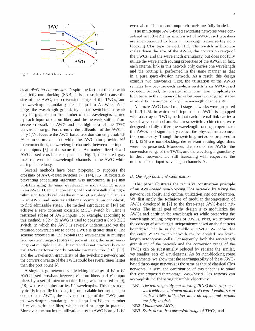
The N × N three-stage AWG-based network under con-sideration, as shown in Fig. 6(a), is a combination of aT (n, r,m) network and a reverseT (n, r,m) network, denotedasSA(n, r,m), whereN = rn is the number of wavelengthchannels andm is the number of central TWC-modules.The wavelength granularity of the networkSA(n, r,m) is|Λ|, which is the same as that of theT (n, r,m). The twofictitious boundaries in the middle of the input and outputTWC-modules are represented by the two dashed lines in Fig.6(a). They divide the entire network into three wavelengthindependent regions, corresponding to the external input wave-length setΩ, the switch wavelength setΛ, and the externaloutput wavelength setΩ′, respectively.
In the networkSA(n, r,m), an input channelI(α, ωi) onthe input TWC-moduleα and an output channelO(β, ω′
j) onthe output TWC-moduleβ can be connected via a centralTWC-module γ, for γ = 0, 1, · · · ,m − 1. According tothe wavelength routing property of the AWG, the centralTWC-moduleγ is connected to the input TWC-moduleα bywavelengthλx, and the output TWC-moduleβ by wavelengthλy, where the indices are given by
x = [α+ γ]|Λ|, (3)
andy = [β + γ]|Λ|. (4)
The wavelengthλx is converted toλy in the middle bythe central TWC-moduleγ. The connection of the callC(α, ωi, β, ω
′j), as shown in Fig. 6, is given by:
I(α, ωi)→ α︸︷︷︸
stage 1
λ[α+γ]|Λ|−−−−−−→ γ
︸︷︷︸
stage 2
λ[γ+β]|Λ|−−−−−−→ β
︸︷︷︸
stage 3
→O(β, ω′j),
which contains the following sequence of wavelength conver-sions:
• input TWC-moduleα : ωi → λx = λ[α+γ]|Λ|,
• central TWC-moduleγ : λx → λy,• output TWC-moduleβ : λy = λ[β+γ]|Λ|
→ ω′j .
Furthermore, if we replace every TWC with a crossbar switch,the SA(n, r,m) is logically equivalent to a symmetric three-stage Clos network [26] with the inter-stage connectionsspecified by (3) and (4) as shown Fig. 6(b).
Similar to the non-blocking condition of Clos networks,two callsC1(α1, ωi1 , β1, ω
′j1) andC2(α2, ωi2 , β2, ω
′j2) in the
SA(n, r,m) cannot share the same central TWC-module ifthey are from the same input TWC-module, i.e.,α1 = α2 = α,or if they are destined for the same output TWC-module,i.e., β1 = β2 = β. It follows that the contentions amongcalls in theSA(n, r,m) can be modeled as a bipartite graphG(V ∪ U,E), in which the vertexvα ∈ V and the vertexuβ ∈ U denote the input TWC-moduleα and the output TWC-moduleβ, respectively, and a callC(α, ω, β, ω′) is represented
6
0 0
m-1r-1
n×m
0
r-1
0
m-1
r×r
m×n
reverse
0
0
m-1
(b)
r-1
r-1
0
m-1
0
r-1
r-1
0
r-1
0
m-1
r-1
0
r-1
r-1
(a)
input TWC-module central TWC-module output TWC-module
switch region output regioninput region
Fig. 6. AWG-based three-stage network: (a)SA(n, r,m) and (b) space representation.
by an edgeeαβ ∈ E that connectsvα anduβ. The bipartitegraphG(V ∪U,E) is n-regular with2r vertices andrn edgesif all input and output wavelength channels in the networkSA(n, r,m) are busy.
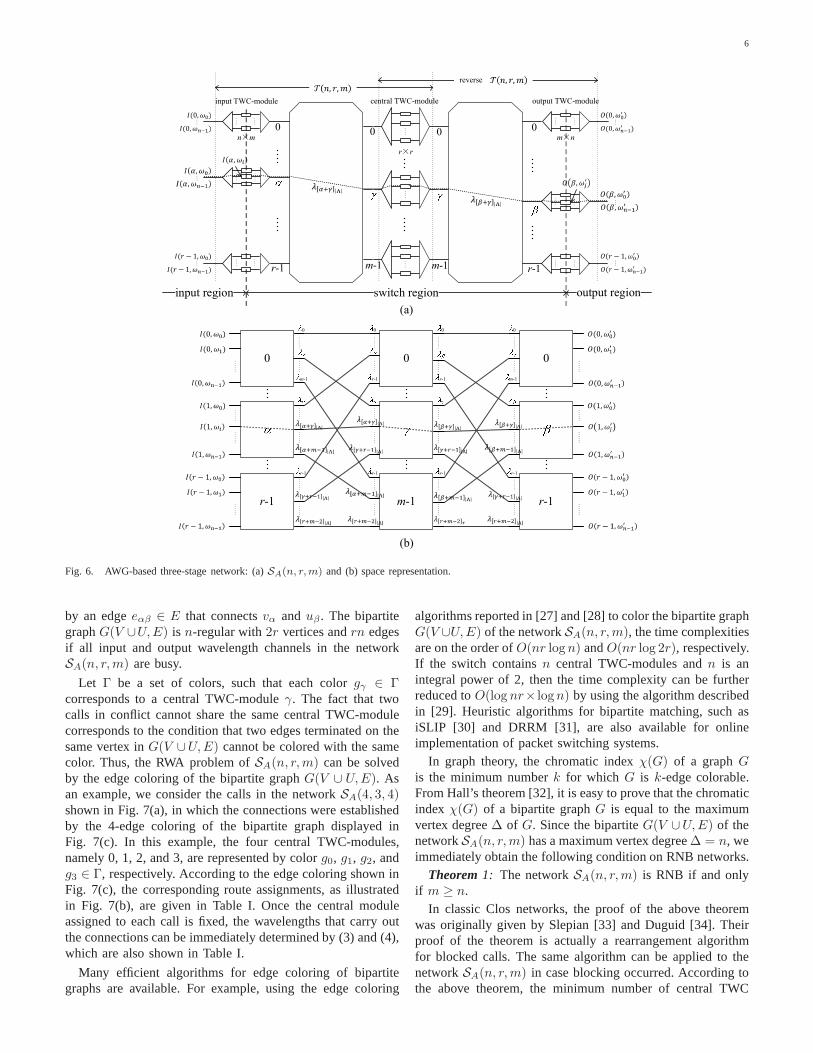
Let Γ be a set of colors, such that each colorgγ ∈ Γcorresponds to a central TWC-moduleγ. The fact that twocalls in conflict cannot share the same central TWC-modulecorresponds to the condition that two edges terminated on thesame vertex inG(V ∪U,E) cannot be colored with the samecolor. Thus, the RWA problem ofSA(n, r,m) can be solvedby the edge coloring of the bipartite graphG(V ∪ U,E). Asan example, we consider the calls in the networkSA(4, 3, 4)shown in Fig. 7(a), in which the connections were establishedby the 4-edge coloring of the bipartite graph displayed inFig. 7(c). In this example, the four central TWC-modules,namely 0, 1, 2, and 3, are represented by colorg0, g1, g2, andg3 ∈ Γ, respectively. According to the edge coloring shown inFig. 7(c), the corresponding route assignments, as illustratedin Fig. 7(b), are given in Table I. Once the central moduleassigned to each call is fixed, the wavelengths that carry outthe connections can be immediately determined by (3) and (4),which are also shown in Table I.
Many efficient algorithms for edge coloring of bipartitegraphs are available. For example, using the edge coloring
algorithms reported in [27] and [28] to color the bipartite graphG(V ∪U,E) of the networkSA(n, r,m), the time complexitiesare on the order ofO(nr logn) andO(nr log 2r), respectively.If the switch containsn central TWC-modules andn is anintegral power of 2, then the time complexity can be furtherreduced toO(log nr× logn) by using the algorithm describedin [29]. Heuristic algorithms for bipartite matching, suchasiSLIP [30] and DRRM [31], are also available for onlineimplementation of packet switching systems.
In graph theory, the chromatic indexχ(G) of a graphGis the minimum numberk for which G is k-edge colorable.From Hall’s theorem [32], it is easy to prove that the chromaticindex χ(G) of a bipartite graphG is equal to the maximumvertex degree∆ of G. Since the bipartiteG(V ∪U,E) of thenetworkSA(n, r,m) has a maximum vertex degree∆ = n, weimmediately obtain the following condition on RNB networks.
Theorem 1: The networkSA(n, r,m) is RNB if and onlyif m ≥ n.
In classic Clos networks, the proof of the above theoremwas originally given by Slepian [33] and Duguid [34]. Theirproof of the theorem is actually a rearrangement algorithmfor blocked calls. The same algorithm can be applied to thenetworkSA(n, r,m) in case blocking occurred. According tothe above theorem, the minimum number of central TWC

7
0
1
2
0
1
2
3
0
1
2
3
1
2
3
0
2
3
0
1
0
1
2
1
2
3
2
3
0
3
0
1
0
1
2
0
1
2
1
2
3
2
3
0
3
0
1
0
1
2
3
1
2
3
0
2
3
0
1
0
1
2
0
1
2
3
0
1
2
0
1
2
3
(a)
(b) (c)
V U
v0
v1
v2
u0
u1
u2
g
g
g
g
C0
C1
C2
C3
C8
C4
C10
C5C6
C7
C9
C11
C0
C1
C2
C3
C8
C4
C10
C5
C6
C7
C9
C11
C0
C1C2 C3
C8
C4
C10
C5
C6 C7
C9C11
Fig. 7. An AWG-based three-stage network: (a)SA(4, 3, 4), (b) space representation, and (c) conflict graph.
TABLE IROUTE AND WAVELENGTH ASSIGNMENT(RWA) FOR THE CALLS IN FIG. 7
Input Central TWC-module outputcall TWC-module (wavelength conversion) TWC-module
C0 0 0 (λ0 → λ0) 0C4 1 0 (λ1 → λ1) 1C8 2 0 (λ2 → λ2) 2
C1 0 1 (λ1 → λ2) 1C5 1 1 (λ2 → λ1) 0C9 2 1 (λ3 → λ3) 2
C2 0 2 (λ2 → λ2) 1C6 1 2 (λ3 → λ0) 0C10 2 2 (λ0 → λ3) 2
C3 0 3 (λ3 → λ1) 0C7 1 3 (λ0 → λ3) 1C11 2 3 (λ1 → λ0) 2
modules required by a rearrangeably non-blocking networkSA(n, r,m) is m = n, in which case the networkSA(n, r, n)has exactlyN = rn TWCs at each stage andN = rnwavelength channels within each AWG. Thus, similar to thesymmetric rearrangeably non-blocking (RNB) Clos networkswith minimum number of central modules, the optimal net-work SA(n, r, n) can also achieve 100% utilization when allinputs and outputs are fully loaded withN = rn calls.
The major goal of the classic three-stage Clos networks isto scale crossbar modules by using a recursive decompositionscheme. However, the AWGs and the conversion range ofcentral TWC-modules in the networkSA(n, r, n) are notscalable. It also emerged as the most intractable issue ofsimilar AWG-based three-stage networks proposed in [24] and
[25]. The complete recursive scheme to achieve the scalabilityof AWG-based Clos networks is described in the next section.
IV. RECURSIVE CONSTRUCTION: AWGMODULARIZATION AND WAVELENGTH REUSE
To achieve our objective NB2∼NB4, we focus our dis-cussion on the modularization of AWGs and the rule toreduce the conversion range of the central TWCs. Withoutloss of generality, we consider the recursive constructionofthe networkSA(n, r, n) with parameterr = nd−1. An examplenetwork is illustrated in Fig. 8, wheren = 2 andd = 4. Thisnd × nd three-stage switch network consists of annd−1 × ninput AWG and ann×nd−1 output AWG with the wavelengthsetΛ = λ0, λ1, · · · , λnd−1−1 in the switch region. Thus, thewavelength granularity of the networkSA(n, n
d−1, n) is nd−1.Also, the conversion range of each input or output TWC isn,while that of central TWCs isnd−1.
We first consider the decomposition of annd−1 × n AWGinto a two-stage network, denoted asNI(n
d−2, n). As shownin Fig. 9, the network consists ofnd−2 n × n AWGs in thefirst stage andn nd−2 × 1 Muxes in the second stage. In thetwo-stage network, the inputα is labeled by the two-tuple(A, a), whereA = ⌊α/n⌋ anda = [α]n, to indicate that it isthe ath input of theAth AWG module. Herein,⌊Y ⌋ denotesthe largest integer smaller thanY . The set of wavelengthsassociated with AWGA is a subsetΛA ⊆ Λ, defined by
ΛA = λAn, · · · , λ(A+1)n−1 (5)
for A = 0, 1, · · · , nd−2−1. In the second stage of the network,the γth output of the AWGA and theAth input of the Mux

8
0
0
1
1
2
3
4
5
6
7
0
1
2
3
4
5
6
7
Fig. 8. An AWG-based three-stage networkSA(2, 24−1, 2).
(0,0) 0
n-1
0
n-1
A
0
n-1
0
n-1
0
n-1
0
(0,n-1)
: (A,a)
(nd-2-1,0)
(nd-2
-1,n-1)
A
nd-2
-1
0
A
0
A
0
n-1
a
n wavelengths
n wavelengths
nd-1
wavelengths
nd-2
-1
nd-2
-1
Fig. 9. Two-stage AWG networkNI(nd−2, n).
γ are connected by an internal link, which carries a stream ofsignals with wavelength setΛA. The following path, denotedasL(A, a, γ), from input (A, a) to outputγ:
(A, a)→ the γth output port of AWGA
→ theAth input port of Muxγ
is connected through the wavelengthλx ∈ ΛA, where
x=An+ [a+ γ]n
= ⌊α/n⌋n+[[α]n + γ
]
n. (6)
Similar to the three-stage decomposition of AWGs describedin [2], the path L(A, a, γ) in the two-stageNI(n
d−2, n)determined by the wavelength routing (6) are contention-freeat both inputs and outputs, as illustrated in the proof of thefollowing lemma.
Lemma 1: The networkNI(nd−2, n) is functionally equiv-
alent to annd−1 × n AWG.Proof: Each input(A, a) and each outputγ of the network
NI(nd−2, n) are connected by the pathL(A, a, γ). We want
to show that these paths are contention-free at each input andeach output if wavelength routing follows the rule specifiedby (6).
Suppose that the two connectionsL1(A1, a1, γ1) andL2(A2, a2, γ2) are originated at the same inputα = (A, a),
0
1
2
3
4
5
6
7
0
1
2
3
0
1
2
3
4
5
6
7
0
1
0
1
0
1
0
1
0
1
0
1
0
1
0
1
0
1
0
1
0
1
2
3
4
5
6
7
OUT 0 OUT 2
IN 0
IN 1
IN 2
IN 3
IN 4
IN 5
IN 6
IN 7
OUT 0 OUT 2
IN 0
IN 1
IN 2
IN 3
IN 4
IN 5
IN 6
IN 7
(a) (b)
Fig. 10. Illustration of AWG decomposition: (a)8× 2 AWG and (b)8× 2two-stage AWG network.
then we have
A1 = A2 = A
a1 = a2 = a,
If L1 andL2 are routed by the same wavelengthλx ∈ ΛA,then, from (6), we have
x = An+ [a+ γ1]n = An+ [a+ γ2]n,
which impliesγ1 = γ2, becauseγ1, γ2 = 0, 1, · · · , n − 1. Itfollows that L1 and L2 are the same connection. Thus, allinputs are contention-free.
Similarly, suppose that the two connectionsL1(A1, a1, γ1)and L2(A2, a2, γ2) are destined for the same output, i.e.,γ1 = γ2 = γ and use the same wavelengthλx ∈ ΛA. Then,

9
0
1
2
3
4
5
6
7
0
1
0
1
2
3
0
1
2
3
0
1
2
3
0
1
2
3
0
1
2
3
4
5
6
7
0
1
0
1
0
1
0
1
0
1
0
1
0
1
0
1
0
1
0
1
0
1
0
1
0
1
0
1
0
1
0
1
central module2 wavelengths 2 wavelengths
8 wavelengths
input AWG output AWG
Fig. 11. Three-stage networkSB(2, 24−1, 2).
centralmodulethoutput
thinput
n×n
AWG
n×n
AWG
switch regionoutput
region
input
region
input AWG
A
output AWG
B
A
B
ath input
bth output
Fig. 12. Connection of a callC(α, ωi, β, ω′
j) in the networkSB(n, nd−1, n).
according to (6), we have
A1n+ [a1 + γ]n = A2n+ [a2 + γ]n,
which implies A1 = A2, because[a1 + γ]n, [a2 + γ]n =0, 1, · · · , n− 1. We therefore have
[a1 + γ]n = [a2 + γ]n,
which implies a1 = a2, becausea1, a2 = 0, 1, · · · , n − 1.Again, the two connectionsL1 andL2 must be the same, andall outputs are also contention-free.
The decomposition of an8 × 2 AWG into the two-stagenetwork NI(4, 2) is illustrated in Fig. 10. The networkNI(4, 2) consists of four2 × 2 AWGs in the first stageand two 4 × 1 Muxes in the second stage. The originalwavelength setΛ = λ0, · · · , λ7 is partitioned into foursubsetsΛ0 = λ0, λ1, Λ1 = λ2, λ3, Λ2 = λ4, λ5, andΛ3 = λ6, λ7, associated with the four corresponding2 × 2AWGs.
Similarly, it is easy to show that ann × nd−1 AWGcan be decomposed into a functionally equivalent two-stagenetworkNO(n, n
d−2), which is a mirror image of the networkNI(n
d−2, n). According to Lemma 1, if the two AWGs inSA(n, n
d−1, n) are replaced by the corresponding networksNI(n
d−2, n) andNO(nd−2, n), then we obtain an equivalent
three-stage network, denoted asSB(n, nd−1, n). For example,
the networkSB(2, 8, 2) shown in Fig. 11 is equivalent tothe network SA(2, 8, 2) displayed in Fig. 8. Then × nAWGs in NI(n
d−2, n) are referred to asinput AWGs, andthose in NO(n
d−2, n) are output AWGs. In the networkSB(n, n
d−1, n), there aren central modules and they possessthe following properties:
P1 There is a unique link between each n × n AWG andeach central module,
P2 Each central module is an nd−1 × nd−1 WDM switch,which consists of an nd−2 × 1 Mux, a central TWC-module, and a 1× nd−2 DeMux,

10
0
1
2
3
4
5
6
7
0
1
2
3
0
1
2
3
0
1
2
3
4
5
6
7
0
1
0
1
0
1
0
1
0
1
0
1
0
1
0
1
0
1
0
1
0
1
0
1
0
1
0
1
0
1
0
1
subnetwork 0
subnetwork 1
central module 1
central module 0longitude
latitude
Fig. 13. Recursive three-stage networkSC(2, 24−1, 2).
0
0
thoutput
thinput
n×n
AWG
n×n
AWG
subnetworkA
B
centralmodule
input AWG
A
output AWG
B
ath input
bth outputlongitude
latitude
0
’
Fig. 14. Connection of a callC(α, ωi, β, ω′
j) in the networkSC(n, nd−1, n).
P3 Each central module is functionally equivalent to annd−1 × nd−1 crossbar, where each input or output ofthe central module carries n wavelengths, and there arend−1 TWC converters with the conversion range of nd−1,
P4 Each central module employs the entire wavelength setΛ = λ0, λ1, · · · , λnd−1−1. According to the non-blocking and contention-free principle, this wavelengthset Λ is not scalable because the single link in eachMux/DeMux pair carries all wavelengths in Λ.
Note that the property P4 implies that the wavelength granu-larity of the networkSB(n, n
d−1, n) is nd−1, the same as thatof the networkSA(n, n
d−1, n).
In the networkSB(2, 8, 2) shown in Fig. 11, the connectionof the call C(3, ω1, 5, ω
′0) yields a sub-call fromI ′(1, λ2)
to O′(2, λ4) in the central module 1. Generally, in the net-work SB(n, n
d−1, n), a stereotyped connection of the callC(α, ω, β, ω′) via central moduleγ will incur a sub-call
C′(A, λx, B, λy), as shown in Fig. 12. In the central moduleγ, the parametersA, B, x, andy of this sub-call are given by
A = ⌊α/n⌋, (7)
B = ⌊β/n⌋, (8)
x = An+ [a+ γ]n = An+[[α]n + γ
]
n, (9)
andy = Bn+ [b+ γ]n = Bn+
[[β]n + γ
]
n. (10)
Despite the fact that the AWGs are modularized in the net-work SB(n, n
d−1, n), it is still not a recursive decompositionscheme because the central modules do not repeat the samethree-stage structure of the entire network. In addition, thewavelength set and the conversion range of TWCs are notscalable due to the properties P3 and P4 above. According to

11
subnetwork 0
subnetwork 1
subnetwork 2
subnetwork 3
Fig. 15. Recursive decomposition of the networkSC(2, 24−1, 2).
the non-blocking and contention-free principle, different input(output) AWGs can reuse the same wavelength set only if theyare either topologically independent or separated by fictitiousboundaries of TWCs.
To achieve the wavelength reuse and retain the propertiesP1 and P2 above, we can logically divide the network intodisjoint cells by the vertical fictitious boundaries in the middleof TWCs, and the horizontal dashed lines between AWG mod-ules. As Fig. 13 illustrates, the wavelengths used by the partof each central module between the two boundaries, referredto as asub-network, can be independent of those wavelengthsets associated with the AWGs and the TWCs outside theseboundaries. If each sub-network repeats the same three-stagestructure of the entire network, we then have a recursivelyconstructed three-stage network, denoted asSC(n, n
d−1, n).Moreover, in this three-stage network, all input and outputTWC-modules and all input and output AWGs can use thesame wavelength set, e.g.,Λ0 = λ0, · · · , λn−1, becausethey are either topologically independent or separated byfictitious boundaries. It follows that the wavelength granularityof the SC(n, n
d−1, n) is n − 1, much smaller than that ofthe networkSA(n, n
d−1, n) andSB(n, nd−1, n). For example,
every cell in theSC(2, 8, 2) shown in Fig. 13 uses the samewavelength setΛ0 = λ0, λ1.
The connection of a call in the networkSC(n, nd−1, n) is
similar to that in theSB(n, nd−1, n) described before. As
an example, Fig. 13 illustrates the connection of the callC(3, ω1, 5, ω
′0) in the networkSC(2, 8, 2). In general, the
connection of a callC(α, ωi, β, ω′j) via central moduleγ in the
networkSC(n, nd−1, n), as Fig. 14 shows, can be expressed
by
I(α, ωi) → α︸︷︷︸
stage 1
λx′
−−→ γ︸︷︷︸
stage 2
λy′
−−→ β︸︷︷︸
stage 3
→ O(β, ω′j),
wherex′ andy′ are given as follows:
x′ = [a+ γ]n =[[α]n + γ
]
n, (11)
andy′ = [b+ γ]n =
[[β]n + γ
]
n. (12)
Similarly, in the network SC(n, nd−1, n), a sub-call
C′(A, λx′ , B, λy′) will be incurred in the central moduleγby this connection of the callC(α, ω, β, ω′).
Collecting the above discussions, we conclude this sectionin the following theorem.
Theorem 2: The networkSC(n, nd−1, n) is an RNB net-
work that achieves the objective NB1∼NB4.Proof: Since the number of central modules in the three-
stage networkSC(n, nd−1, n) is n, according to Theorem
1, it is RNB if every central module is RNB. In addition,according to Lemma 1, the wavelength assignments based on(11) and (12) are contention-free. Next, we want to show thatthe objective NB1∼NB4 can be achieved by this recursivenetwork.
In the networkSC(n, nd−1, n), there arend−1 n× n input
(output) TWC-modules that totally containN = nd TWCs,and nd−2 n × n input (output) AWGs. When allN = nd
wavelength channels are active, all input (output) TWCs andall input (output) AWGs of the networkSC(n, n
d−1, n) arefully occupied. Also, as we discussed above, all TWCs andAWGs are associated with the same wavelength setΛ0, as Fig.14 illustrates. Thus, the first and third stages of the networkSC(n, n
d−1, n) fulfill the objective NB1∼NB4. Moreover,each sub-network in the central module repeats the same three-stage structure of the entire network, and the wavelengthsused by the sub-networks are independent of those wavelengthsets associated with the TWCs and AWGs outside theseboundaries. It follows that alln central modules can alsofulfill these objectives if we repeatedly apply the recursivedecomposition schemeSC(n, n
d−1, n) to each central module.
An example is illustrated in Fig. 15, which is obtained by thedecomposition of the central modules ofSC(2, 8, 2) networkshown in Fig. 13. It is clear that all TWC-modules and AWGmodules can be associated with the same wavelength setΛ0,and fulfill the objective NB1∼NB4.
Repeatedly applying the recursive scheme, a WDM networkwith N = nd input and output channels can be constructedby n × n TWC-modules andn × n AWGs associated with

12
stage 1 stage 2 stage 3 stage 4 stage 5 stage 6 stage 7
0
1
2
3
4
5
6
7
0
1
2
3
4
5
6
7
0
1
2
3
4
5
6
7
0
1
2
3
4
5
6
7
0
1
2
3
4
5
6
7
0
1
2
3
4
5
6
7
0
1
2
3
4
5
6
7
(a)
stage 1 stage 2 stage 3 stage 4 stage 5 stage 6 stage 7call TWC-module TWC-module TWC-module TWC-module TWC-module TWC-module TWC-module
(conversion) (conversion) (conversion) (conversion) (conversion) (conversion) (conversion)C0(0, ω0, 7, ω′
1) 0 (ω0 → λ0) 0 (λ0 → λ0) 0 (λ0 → λ1) 1 (λ1 → λ0) 1 (λ0 → λ1) 3 (λ1 → λ1) 7 (λ1 → ω′
1)
C1(0, ω1, 6, ω′
1) 0 (ω1 → λ1) 4 (λ1 → λ0) 4 (λ0 → λ0) 4 (λ0 → λ1) 5 (λ1 → λ1) 7 (λ1 → λ1) 6 (λ1 → ω′
1)
C2(1, ω0, 3, ω′
1) 1 (ω0 → λ0) 4 (λ0 → λ1) 6 (λ1 → λ0) 6 (λ0 → λ0) 6 (λ0 → λ0) 5 (λ0 → λ0) 3 (λ0 → ω′
1)
C3(1, ω1, 0, ω′
1) 1 (ω1 → λ1) 0 (λ1 → λ1) 2 (λ1 → λ1) 3 (λ1 → λ1) 2 (λ1 → λ1) 6 (λ1 → λ0) 0 (λ0 → ω′
1)
C4(2, ω0, 4, ω′
1) 2 (ω0 → λ1) 5 (λ1 → λ1) 4 (λ1 → λ1) 5 (λ1 → λ0) 5 (λ0 → λ0) 6 (λ0 → λ1) 4 (λ1 → ω′
1)
C5(2, ω1, 4, ω′
0) 2 (ω1 → λ0) 1 (λ0 → λ1) 0 (λ1 → λ0) 0 (λ0 → λ1) 1 (λ1 → λ0) 2 (λ0 → λ0) 4 (λ0 → ω′
0)
C6(3, ω0, 3, ω′
0) 3 (ω0 → λ1) 1 (λ1 → λ0) 2 (λ0 → λ0) 2 (λ0 → λ0) 2 (λ0 → λ0) 1 (λ0 → λ1) 3 (λ1 → ω′
0)
C7(3, ω1, 5, ω′
1) 3 (ω1 → λ0) 5 (λ0 → λ0) 6 (λ0 → λ1) 7 (λ1 → λ0) 7 (λ0 → λ1) 6 (λ1 → λ0) 5 (λ0 → ω′
1)
C8(4, ω0, 5, ω′
0) 4 (ω0 → λ0) 2 (λ0 → λ1) 3 (λ1 → λ1) 2 (λ1 → λ1) 3 (λ1 → λ1) 2 (λ1 → λ1) 5 (λ1 → ω′
0)
C9(4, ω1, 7, ω′
0) 4 (ω1 → λ1) 6 (λ1 → λ1) 7 (λ1 → λ1) 6 (λ1 → λ1) 7 (λ1 → λ0) 7 (λ0 → λ0) 7 (λ0 → ω′
0)
C10(5, ω0, 2, ω′
1) 5 (ω0 → λ0) 6 (λ0 → λ0) 5 (λ0 → λ1) 4 (λ1 → λ0) 4 (λ0 → λ1) 5 (λ1 → λ1) 2 (λ1 → ω′
1)
C11(5, ω1, 2, ω′
0) 5 (ω1 → λ1) 2 (λ1 → λ0) 1 (λ0 → λ0) 6 (λ0 → λ1) 0 (λ1 → λ1) 1 (λ1 → λ0) 2 (λ0 → ω′
0)
C12(6, ω0, 1, ω′
1) 6 (ω0 → λ0) 3 (λ0 → λ1) 1 (λ1 → λ1) 0 (λ1 → λ0) 0 (λ0 → λ0) 0 (λ0 → λ1) 1 (λ1 → ω′
1)
C13(6, ω1, 0, ω′
0) 6 (ω1 → λ1) 7 (λ1 → λ1) 5 (λ1 → λ0) 5 (λ0 → λ1) 4 (λ1 → λ0) 4 (λ0 → λ1) 0 (λ1 → ω′
0)
C14(7, ω0, 1, ω′
0) 7 (ω0 → λ0) 7 (λ0 → λ0) 7 (λ0 → λ0) 7 (λ0 → λ1) 6 (λ1 → λ1) 4 (λ1 → λ0) 1 (λ0 → ω′
0)
C15(7, ω1, 6, ω′
0) 7 (ω1 → λ1) 3 (λ1 → λ0) 3 (λ0 → λ0) 3 (λ0 → λ0) 3 (λ0 → λ0) 3 (λ0 → λ0) 6 (λ0 → ω′
0)
(b)
Fig. 16. A fully loaded AWG-based three-stage network: (a)B(2, 4) and (b) the route and wavelength assignment.
a set ofn wavelengthsΛ0 = λ0, · · · , λn−1. In particular,if we apply the decomposition schemed − 2 times to thenetworkSA(n, n
d−1, n), then we obtain an AWG-based three-stage network denoted asB(n, d), which consists of2d − 1columns of n × n TWC-modules and2d − 2 columns ofn × n AWGs. Clearly, the wavelength granularity of thenetwork B(n, d) is n, which is only 1/nd−2 of that of thenetwork SA(n, n
d−1, n). For example, the network shownin Fig. 16(a) is the AWG-based three-stage networkB(2, 4)with wavelength granularity 2. The route and wavelengthassignments tabulated in Fig. 16(b) illustrate that the AWG-based three-stage network can achieve 100% utilization whenall input wavelength channels are busy.
Therefore, anN × N AWG-based three-stage networkB(n, d) can be recursively constructed from a set ofn × nAWGs together with a collection of TWCs with conversionrangen, whereN = nd. There is an inherent tradeoff betweenthe physical interconnection complexity and the wavelengthgranularity in the AWG-based WDM switches, and this pointcan be demonstrated by a comparison between the networkB(2, 4) shown in Fig. 16(a) and the networkB(4, 2) displayedin Fig. 17. The number of interconnection links between two
0
1
2
3
0
1
2
3
0
1
2
3
0
1
2
3
Fig. 17. An AWG-based three-stage networkB(4, 2).
adjacent stages in anN ×N electronic three-stage network isN or nd, while the counterpart in an AWG-based three-stagenetwork B(n, d) is nd−1, because each link inB(n, d) cansimultaneously carryn wavelength channels. This reductionfactorn of interconnection complexity can be significant ifnis large, which is achieved at the expense of increasing thesize of AWG modules and the conversion range of TWCs.
In the practical implementation of the AWG-based three-

13
TABLE IICOMPARISON OF DIFFERENTAWG-BASED SWITCHING NETWORKS
NB1 NB2 NB3 NB4 physicalSchemes (100% utilization) (modular AWG) (scalable TWC) (wavelength reuse) interconnection complexity
AWG-based Crossbar[3], [7], [12]–[15] no no no no O(1)
Single-stage network[9] no no no no O(N)
Multi-stage network[19]–[21] no yes yes yes O(N)
SA(n, r,m)[24], [25], Theorem 1 yes no no no O(1)
SB(n, r,m) yes yes no no O(N/n)B(n, d), Theorem 2 yes yes yes yes O(N/n)
stage networkB(n, d), due to current state of art, we shouldtake the following limitations into consideration:
1) Coherent crosstalk: Letp (in dB) be the power penaltyinduced by the coherent crosstalk of ann × n AWGwhen all input wavelengths are the same. Since there are2 logn N stages ofn × n AWGs in anN × N B(n, d)network, the overall power penalty of each connection is2p logn N if there is no compensation mechanism withinthe network;
2) Amplified spontaneous emission (ASE) noise: Semi-conductor optical amplifiers (SOAs) are the key com-ponents of a compact all-optical TWC. The ASE noisegenerated by SOAs will decrease the optical signal-to-noise ratio (OSNR). Therefore, if SOA-based all-opticalTWCs without regenerative function are used, then theOSNR will be faded with the increasing number of stages;
3) Insertion loss: A typical AWG has a∼6-dB insertion loss.
These limitations could be relaxed as follows. First, keepnsmaller than 15 [6] such that the coherent crosstalk can becompensated at the outputs of eachn × n AWG. Second,use all-optical regenerative TWCs [35], [36] or optic-electron-optic (O-E-O) TWCs [3] in the network such that 3R signalregenerations can be performed stage by stage. In practice,it isfeasible to use O-E-O TWCs now because high-speed (∼100GHz) transceivers are already commercially available.
With the maturity of photonics integrated circuits, themodular construction of an optical switch by using opticalintegrated modules is gradually workable. For example, the8× 8 AWG-based crossbar on a III/V photonics chip reportedin [3] demonstrates the feasibility of the integration of eachstage of theB(n, d) network on a single photonics chip.However, it is still difficult to integrate the entire optical switchnetwork, including the optical switching fabric and the elec-tronic controller, on a single chip based on silicon-on-insulate(SOI) technology, despite the fact that the silicon-based AWGs[37], and the silicon-based modulator and detector [38], thekey component of the O-E-O TWC, are both commerciallyavailable. The bottleneck is the unexplored technique of asilicon-based optical laser, an essential component of theTWC. Another challenge of the integration on a single chipis that of the crosspoints of the interconnection links betweentwo adjacent stages, since additional crosstalk and loss couldbe incurred if the number of crosspoints is too large.
V. CONCLUSION
This paper proposes a recursive scheme for the constructionof AWG-based non-blocking Clos networks. In respect tothe network scalability and optimal utilization criteria,thisrecursive approach outperforms the previous schemes in thefollowing aspects. First, it can construct a large-scale networkby a collection of small-sized AWGs while preserving thecomplete wavelength routing property. Second, it logicallydivides the WDM switch network into wavelength independentcells, such that a similar, but smaller, set of wavelengths canbe reused by these cells, which substantially scales down thewavelength granularity and the conversion range of TWCs.Third, the route assignments in these recursive networks areconsistent with those in the classical Clos networks, and thusthe optimal AWG-based RNB Clos network can achieve 100%utilization when all input and output wavelength channels arebusy. For comparison purposes, Table II lists all known resultson the AWG-based multistage networks.
REFERENCES
[1] M. Salsi et al., “Transmission of 96×100Gb/s with 23% super-FECoverhead over 11,680km, using optical spectral engineering,” in Proc.OFC, 2011, p. OMR2.
[2] T. Ye, T. T. Lee, and W. Hu, “A study of modular AWGs for large-scale optical switching systems,”J. Lightw. Technol., vol. 30, no. 13,pp. 2125–2133, Jun. 2012.
[3] D. J. Blumenthalet al., “Integrated photonics for low-power packetnetworking,” IEEE J. Sel. Topics Quantum Electron., vol. 17, no. 2,pp. 458–471, Mar./Apr. 2011.
[4] Y. Liu et al., “Error-free all-optical wavelength conversion at 160 Gb/susing a semiconductor optical amplifier and an optical bandpass filter,”J. Lightw. Technol., vol. 24, no. 1, pp. 230–236, Jan. 2006.
[5] ——, “Error-free 320-Gb/s all-optical wavelength conversion using asingle semiconductor optical amplifier,”J. Lightw. Technol., vol. 25,no. 1, pp. 103–109, Jan. 2007.
[6] R. Gaudino, G. A. G. Castillo, F. Neri, and J. M. Finochietto, “Simpleoptical fabrics for scalable terabit packet switches,” inProc. IEEE ICC,2008, pp. 5331–5337.
[7] A. Bianco, D. Hay, and F. Neri, “Crosstalk-preventing scheduling insingle and two-stage AWG-based cell switches,”IEEE/ACM Trans.Netw., vol. 19, no. 1, pp. 142–155, Feb. 2011.
[8] V. Mikhailov, C. Doerr, and P. Bayvel, “Ultra low coherent crosstalk,high port-count free-space wavelength router,” inProc. OFC, Mar. 2003,pp. 257–258.
[9] A. Pattavina and R. Zanzottera, “Non-blocking WDM switches based onarrayed waveguide grating and shared wavelength conversion,” in Proc.IEEE INFOCOM, 2006.
[10] G. Weichenberg, V. W. S. Chan, and M. Gedard, “Design andanalysis ofoptical flow-switched networks,”IEEE J. Opt. Commun. Netw., vol. 1,no. 3, pp. B81–B97, Aug. 2009.
[11] C. Clos, “A study of nonblocking switching networks,”Bell SystemTechnology Journal, vol. 32, no. 2, pp. 406–424, Mar. 1953.

14
[12] J. Cheynset al., “Routing in an AWG-based optical packet switch,”Photon. Network Commun., vol. 5, pp. 69–80, Jan. 2003.
[13] Z. Panet al., “Advanced optical-label routing system supporting mul-ticast, optical TTL, and multimedia applications,”J. Lightw. Technol.,vol. 23, no. 10, pp. 3270–3281, Oct. 2005.
[14] D. Lucerna, G. Maier, and A. Pattavina, “AWG-based architecture foroptical interconnection in asynchronous systems,” inProc. IEEE HPSR,2011, pp. 250–255.
[15] M. Maier, M. Reisslein, and A.Wolisz, “High-performance switchlessWDM network using multiple free spectral ranges of an arrayed-waveguide grating,” inProc. SPIE Photonics East Terabit OpticalNetworking: Architecture, Control, and Management Issues, vol. 4213,2000, pp. 101–112.
[16] S. Kamei, M. Ishii, A. Kaneko, T. Shibata, and M. Itoh, “NxNcyclic-frequency router with improved performance based on arrayed-waveguide grating,”J. Lightw. Technol., vol. 27, no. 18, pp. 4097–4014,Sep. 2009.
[17] F. Liu, R. J. S. Pedersen, and P. Jeppesen, “Very low crosstalkwavelength router construction using arrayed-waveguide gratingmulti/demultiplexers,”Electron. Lett., vol. 35, pp. 839–840, May 1999.
[18] J. Ramamirtham and J. S. Turner, “Design of wavelength convertingswitches for optical burst switching,” inProc. IEEE INFOCOM, 2002,pp. 1162–1171.
[19] J. Cheynset al., “Clos lives on in optical packet switching,”IEEECommun. Mag., vol. 42, no. 2, pp. 114–121, Feb. 2004.
[20] H. Q. Ngo, D. Pan, and C. Qiao, “Constructions and analyses ofnonblocking WDM switches based on arrayed waveguide grating andlimited wavelength conversion,”IEEE/ACM Trans. Netw., vol. 14, no. 1,pp. 205–217, Feb. 2006.
[21] R. Zanzotteraet al., “Design of OXC architectures based on arrayedwaveguide gratings: Topological properties and physical performance,”in Proc. IEEE HPSR, 2006.
[22] S. Bregni, A. Pattavina, and G. Vegetti, “Architectures and performanceof AWG-based optical switching nodes for ip networks,”IEEE J. Sel.Areas Commun., vol. 21, no. 7, pp. 1113–1121, Sep. 2003.
[23] M. Maier and M. Reisslein, “AWG-based metro WDM networking,”IEEE Commun. Mag., vol. 42, no. 11, pp. s19–s26, Nov. 2004.
[24] W. D. Zhong, J. P. Lacey, and R. Tucker, “Multiwavelength cross-connects for optical transport networks,”J. Lightw. Technol., vol. 14,no. 7, pp. 1613–1620, Jul. 1996.
[25] J. J. G. Leonardus, “Non-blocking cyclic AWG-based node architec-tures,” EU patent: EP1761103, Mar. 2007.
[26] T. T. Lee and S. C. Liew,Principle of broadband switching andnetworking. Wiley-Interscience, 2010, ch. 2.
[27] R. Cole, K. Ost, and S. Schirra, “Edge-coloring bipartite multigraphs inO(ElogD) time,” Combinatorica, vol. 21, no. 1, pp. 5–12, Jan. 2001.
[28] T. T. Lee, Y. Wan, and H. Guan, “Randomized∆-edge colouringvia exchanges of complex colours,”International Journal of ComputerMathematics, vol. 90, no. 2, pp. 228–245, Feb. 2013.
[29] T. T. Lee and S. Y. Liew, “Parallel routing algorithms inBenes-Closnetwork,” IEEE Trans. Commun., vol. 50, no. 11, pp. 1841–1847, Nov.2002.
[30] N. McKeown, “The iSLIP scheduling algorithm for input-queuedswitches,” IEEE/ACM Trans. Netw., vol. 7, no. 2, pp. 188–201, Apr.1999.
[31] H. J. Chao, C. Lam, and E. Oki,Broadband packet switching technolo-gies - a practical guide to ATM switches and IP routers. Wiley, 2001.
[32] P. Hall, “On representatives of subsets,”J. London Math Soc., vol. 10,pp. 26–30, 2003.
[33] D. Slepian, “Two theorems on a particular crossbar switching network,”1952, unpublished manuscript.
[34] A. M. Duguid, “Structural properties of switching networks,” BrownUniversity, Tech. Rep., 1959, bTL-7.
[35] H. Chayetet al., “Regenerative all-optical wavelength converter basedon semiconductor optical amplifier and sharp frequency response filter,”in Proc. OFC, 2004, p. ThS2.
[36] C. Porzi, A. Bogoni, and G. Contestabile, “Regenerative wavelengthconversion of DPSK signals through FWM in an SOA,”IEEE Photon.Technol. Lett., vol. 25, no. 2, pp. 175–178, Jan. 2013.
[37] S. T. Cheunget al., “Low-loss and high contrast silicon-on-insulator(SOI) arrayed waveguide grating,” inProc. CLEO, 2012, p. CM4A.5.
[38] A. Dhiman, “Silicon photonics: a review,”IOSR Journal of AppliedPhysics, vol. 3, no. 5, pp. 67–79, Mar./Apr. 2013.