Embed Size (px)
Citation preview
AWE CORE™
INTEGRATION GUIDE
DSP Concepts, Inc. AWE Core™ Integration Guide
Back to Table of Contents Page: 2 of 49 (v13)
Copyright Information
© 2006-2018 DSP Concepts, Inc., ALL RIGHTS RESERVED. This document may not be
reproduced in any form without prior, express written consent from DSP Concepts, Inc.
Printed in the USA.
Disclaimer
DSP Concepts, Inc. reserves the right to change this product without prior notice. Information
furnished by DSP Concepts is believed to be accurate and reliable. However, no responsibility is
assumed by DSP Concepts for its use; nor for any infringement of patents or other rights of third
parties which may result from its use. No license is granted by implication or otherwise under the
patent rights of DSP Concepts, Inc.
DSP Concepts, Inc. AWE Core™ Integration Guide
Back to Table of Contents Page: 3 of 49 (v13)
Change Log
Version Date Description Author
01 2016.Oct.11 Updated for AWE v5 functionality MW
02 2016.Oct.28 Reorganization MW
03 2016.Nov.1 Expanded Theory of Operation / Control Model MW
04 2016.Nov.8 Added Figure cross-references and simplified control interface. MW
05 2016.Dec.20 Fixed typos AN
06 2017.Mar.24 Revised for AWE v6 functionality CHP
07 2017.Mar.27 Added some doc-navigation, corrected text, updated naming conventions MW
08 2017.Mar.29 Corrected prototype for awe_fwPacketExecuteArray() MW
09 2017.Aug.10 Updated Control Interface section with proper source structure fields MM
10 2017.Dec.17 Added detailed information on BSP prerequisities PB
11 2018.Jan.3 Added missing AWE-6 changes CHP
12 2018.Feb.11 Fixed typos and added missing details to audio processing code example CHP
13 2018.Jun.21 Added rev to footer MW
DSP Concepts, Inc. AWE Core™ Integration Guide
Back to Table of Contents Page: 4 of 49 (v13)
Table of Contents
Table of Contents ........................................ 4
Table of Figures .......................................... 5
1. Introduction ......................................... 7
2. Theory of Operation ............................ 7
2.1. Data Interfaces ............................ 7
2.2. Dynamic Instantiation ................. 8
2.3. Tuning Model .............................. 9
2.4. Control Model ........................... 14
2.5. Audio-Processing Model .......... 19
2.6. Threading / Priority Model ....... 22
3. Tuning Interface ................................ 24
3.1. Overview ................................... 24
3.2. Integration Quick Guide ............ 24
3.3. Tuning API ................................ 25
3.4. Message Structure ..................... 26
3.5. RS-232 Protocol ........................ 26
3.6. SPI Protocol .............................. 28
3.7. USB Protocol ............................ 29
3.8. Error Handling .......................... 29
4. Audio Interface ................................. 30
4.1. Overview ................................... 30
4.2. Audio Processing ...................... 31
4.3. Audio API ................................. 32
4.4. Detailed Integration Steps ......... 33
5. Control Interface ............................... 37
5.1. Overview ................................... 37
5.1. ObjectID allocation ................... 38
5.2. Control API ............................... 38
5.3. Detailed Integration Steps ......... 39
6. Global Variables and Data Structures 42
6.1. Memory Heaps .......................... 43
6.2. Module Table ............................ 43
6.3. Optimizing Memory Usage ....... 44
6.4. Target Info ................................. 45
6.5. Communication Buffer ............. 45
6.6. Memory Sections ...................... 46
7. Framework Prerequisites................... 47
7.1. Basic Processor and Board
Initialization .......................................... 47
7.2. Simple “Audio Passthru”
Application ............................................ 47
7.3. Simple “Echo-Back” Application
48
7.4. Basic Interrupts and Threading
Configured ............................................ 49
7.5. Optional: Flash memory ............ 49
DSP Concepts, Inc. AWE Core™ Integration Guide
Back to Table of Contents Page: 5 of 49 (v13)
Table of Figures
Figure 1. The three data interfaces to the AWE Core ..................................................................... 7
Figure 2. Example commands that dynamically create a signal processing Layout at runtime ...... 8
Figure 3. Standalone operation from compiled-in AWB. ............................................................. 11
Figure 4. InitCommands array generated by AWE Designer ........................................................ 12
Figure 5. AWB stored in SPI FLASH ........................................................................................... 12
Figure 6. External micro controller managing FLASH contents .................................................. 13
Figure 7. Example SOC implementation of Tuning interface ...................................................... 14
Figure 8. Simple example of Control data in a layout. ................................................................. 15
Figure 9. Multi-input control convention ...................................................................................... 16
Figure 10. Diagram of static DMA-blocksize versus ‘tunable’ processing-blocksize. ................. 20
Figure 11. Channel-count is in the Layout is independent of the hardware. ................................. 21
Figure 12. An audio design with multiple block sizes. ................................................................ 23
Figure 13. Processor activity when audio processing occurs in multiple threads. ....................... 24
Figure 14. Tuning Command and Reply Format .......................................................................... 26
Figure 15. Tuning protocol CRC Calculation ............................................................................... 26
Figure 16. Block based audio processing using double buffered DMA. ...................................... 31
Figure 17. Mapping ISR to interrupt on SHARC ......................................................................... 32
Figure 18. Simple system showing Source and Sink models as Layout Control I/O interfaces. .. 37
Figure 19. Assign a static ObjectID to a control interface module. .............................................. 38
Figure 20. Source and Sink Modules ............................................................................................ 39
Figure 21. Example code that writes control data into the Layout Error! Bookmark not defined.
Figure 22. Module Table ............................................................................................................... 43
Figure 23. List of Module Classes ................................................................................................ 44
DSP Concepts, Inc. AWE Core™ Integration Guide
Back to Table of Contents Page: 6 of 49 (v13)
Figure 24. Module Classes used in a layout .................................................................................. 45
DSP Concepts, Inc. AWE Core™ Integration Guide
Back to Table of Contents Page: 7 of 49 (v13)
1. Introduction
The AWE Core™ is an embedded, dynamically-configured audio-processing engine. This
document describes the theory of operation and how to integrate this software-engine into a
products’ embedded software. The intended audience is embedded software engineers familiar
with real-time embedded-audio systems.
2. Theory of Operation
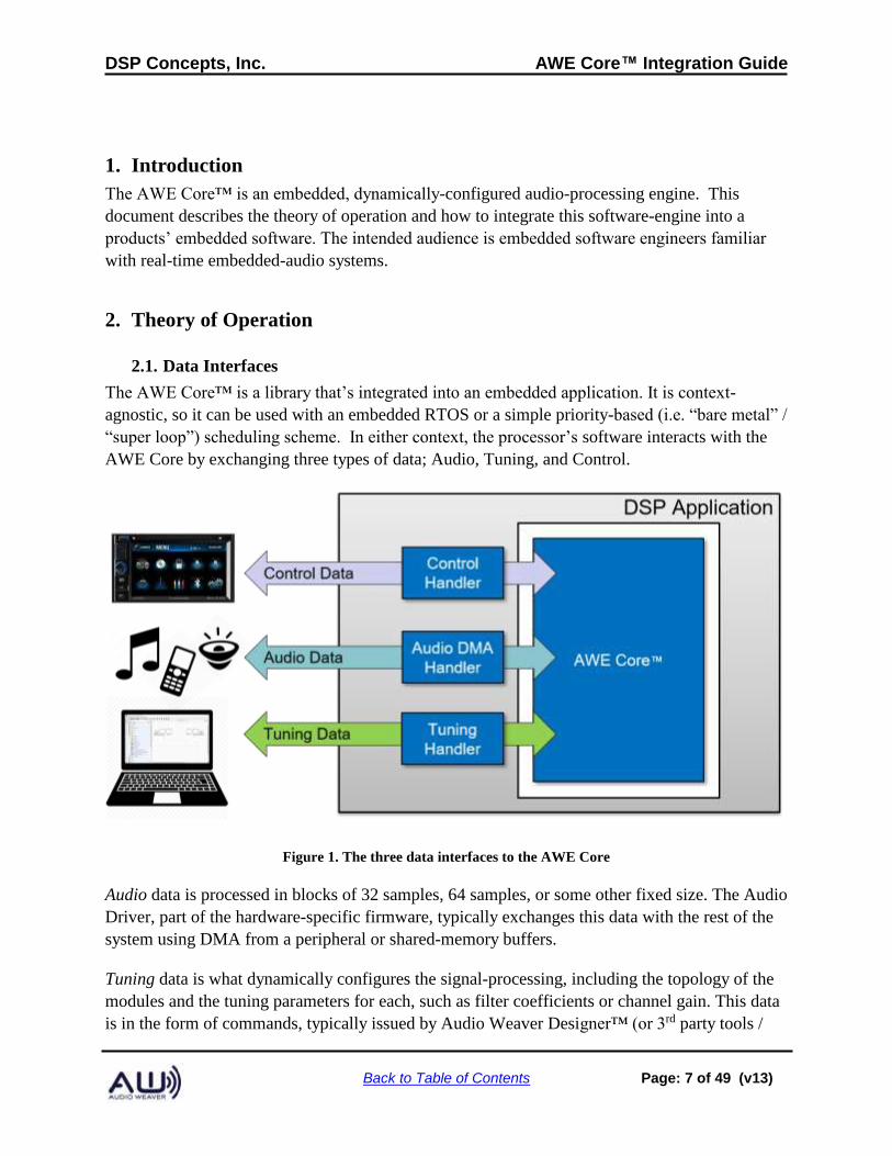
2.1. Data Interfaces
The AWE Core™ is a library that’s integrated into an embedded application. It is context-
agnostic, so it can be used with an embedded RTOS or a simple priority-based (i.e. “bare metal” /
“super loop”) scheduling scheme. In either context, the processor’s software interacts with the
AWE Core by exchanging three types of data; Audio, Tuning, and Control.
Figure 1. The three data interfaces to the AWE Core
Audio data is processed in blocks of 32 samples, 64 samples, or some other fixed size. The Audio
Driver, part of the hardware-specific firmware, typically exchanges this data with the rest of the
system using DMA from a peripheral or shared-memory buffers.
Tuning data is what dynamically configures the signal-processing, including the topology of the
modules and the tuning parameters for each, such as filter coefficients or channel gain. This data
is in the form of commands, typically issued by Audio Weaver Designer™ (or 3rd party tools /
DSP Concepts, Inc. AWE Core™ Integration Guide
Back to Table of Contents Page: 8 of 49 (v13)
scripts). The Audio Weaver Server manages the tuning interface on the PC side and supports the
following transport mechanisms:
• USB
• RS-232
• SPI
• Ethernet
The Tuning Driver, developed by the integrator, may control a peripheral, such as a UART or
USB port, or it may receive tuning commands via sockets, shared memory, or some other IPC
mechanism. The Tuning Driver exchanges commands and replies between the AWE Core using
one of the tuning transports listed above.
Control data typically represents HMI (human-machine interface) settings, such as volume,
balance, or system-state, such as battery-level. Being a bidirectional interface, data calculated in
the AWE Core (e.g. RMS level, event-detection flags, or a direction-of-arrival estimate) may also
be retrieved from the control interface.
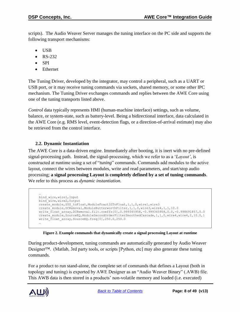
2.2. Dynamic Instantiation
The AWE Core is a data-driven engine. Immediately after booting, it is inert with no pre-defined
signal-processing path. Instead, the signal-processing, which we refer to as a ‘Layout’, is
constructed at runtime using a set of “tuning” commands. Commands add modules to the active
layout, connect the wires between modules, write and read parameters, and start/stop audio
processing; a signal processing Layout is completely defined by a set of tuning commands.
We refer to this process as dynamic instantiation.
…
bind_wire,wire1,Input
bind_wire,wire2,Output
create_module,SYS_toFloat,ModuleFract32ToFloat,1,1,0,wire1,wire3
create_module,DCRemoval,ModuleButterworthFilter,1,1,0,wire3,wire4,1,1,10.0
write_float_array,DCRemoval.filt.coeffs[0],0.999345958,-0.999345958,0.0,-0.998691857,0.0
create_module,SourceEQ,ModuleSecondOrderFilterSmoothedCascade,1,1,0,wire4,wire4,2,10.0,1
write_float_array,SourceEQ.freq[0],250.0,250.0
…
Figure 2. Example commands that dynamically create a signal processing Layout at runtime
During product-development, tuning commands are automatically generated by Audio Weaver
Designer™. (Matlab, 3rd party tools, or scripts [Python, etc] may also generate these tuning
commands.
For a product to run stand-alone, the complete set of commands that defines a Layout (both in
topology and tuning) is exported by AWE Designer as an “Audio Weaver Binary” (.AWB) file.
This AWB data is then stored in a products’ non-volatile memory and loaded (i.e. executed)
DSP Concepts, Inc. AWE Core™ Integration Guide
Back to Table of Contents Page: 9 of 49 (v13)
during post-boot init.
Note: To facilitate dynamic instantiation, the AWE Core has its own memory manager, with
three dedicated memory heaps: Fast, FastB, and Slow. As described in Section 6.1, the system
developer is expected to place these three heaps in appropriate memory.
2.3. Tuning Model
A signal-processing Layout is instantiated in the AWE core through a set of Tuning commands.
Fom the perspective of the integrator and system designer, there are two scenarios to understand -
based on the origin of the tuning commands.
First, while a new product is being developed, DSP Engineers, Acoustic Engineers, and System
Engineers will use PC-based tools like AWE Designer to create and refine the signal processing
Layout. During this phase, commands are sent to the AWE Core from the PC in realtime.
Later, when developers are done tweaking and tuning a product’s signal-processing Layout, it
must be stored in a product’s NVRAM so the product can operate standalone. The method of
storing and loading a Layout from NVRAM will vary from product to product and is an
engineering exercise for the integrator (though Reference Integrations of various forms are
available for free from DSP Concepts).
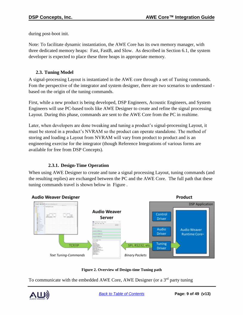
2.3.1. Design-Time Operation
When using AWE Designer to create and tune a signal processing Layout, tuning commands (and
the resulting replies) are exchanged between the PC and the AWE Core. The full path that these
tuning commands travel is shown below in Figure .
Figure 2. Overview of Design-time Tuning path
To communicate with the embedded AWE Core, AWE Designer (or a 3rd party tuning
DSP Concepts, Inc. AWE Core™ Integration Guide
Back to Table of Contents Page: 10 of 49 (v13)
application / script) first connects to a PC application called the Audio Weaver Server [using
TCP/IP]. The typical scenario is that both AWE Designer and AWE Server are running locally
on the same computer using “localhost”. Communication occurs using human-readable tuning
commands. Scripts containing these commands are called Audio Weaver Scripts (AWS). AWE
Server then converts each text command into a binary packet and sends them out over the
specified tuning transport (e.g. Ethernet, USB, RS232, etc.) to the target platform. Scripts
containing these binary commands are called Audio Weaver Binary (AWB) scripts.
Note: Figure 2 above shows some example AWS commands. The full list of commands and their
arguments is detailed in the Audio Weaver Server Command Syntax document
In the Application software on the target, a Tuning Driver must be developed to handle the
chosen tuning transport/peripheral. This tuning driver may respond to DMA interrupts from an
on-chip peripheral, such as UART or SPI, or it may process packets received via USB, network,
or shared-memory. The Tuning Driver passes the received tuning data to the AWE Core and
sends replies back to the PC when they are ready. The Tuning Driver is simply a data-handler,
exchanging messages between the tuning transport and the AWE Core. It may have to run at a
fairly high priority in order not to miss communication events but the actual command handling
must be done in a deferred procedure call at a priority lower than the signal processing. Note: this
command protocol is driven by AWE Server. The server issues a command and will not issue
another command until the original command is complete or times out. There are never
unsolicited commands or replies.
The API that the Tuning Driver uses to interact with AWE Core is described below in section 3.
2.3.2. Standalone Operation
Once configuration and tuning is complete, a Layout can be saved on the product to allow stand
alone operation. To do this, the Layout is exported as an Audio Weaver Binary (.AWB) file. (In
AWE Designer, select Tools / Generate Target Files). AWB’s may be stored in-product in two
ways: either ‘compiled-in’, where the AWB is embedded as static data in the processor’s
executable, or as a separate data-object stored in NVRAM.
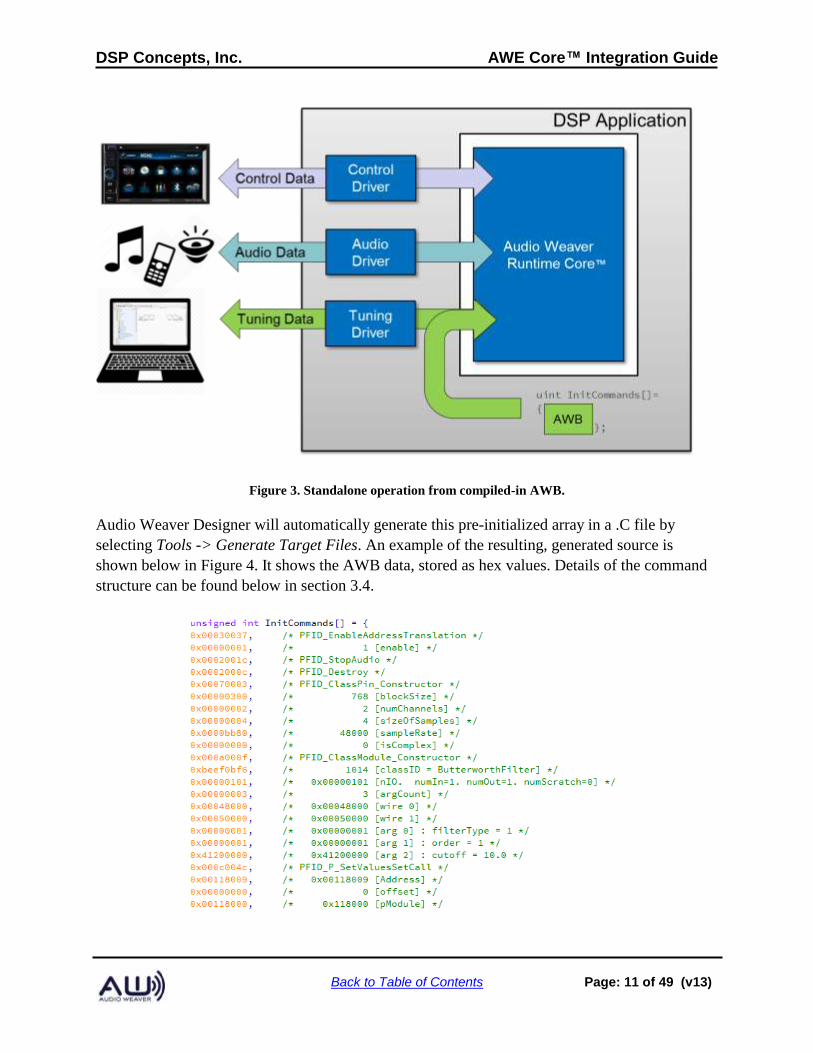
2.3.2.1. Compiled-in AWB
The simplest way to store and load an AWB is to initialize a C-array with the contents of the
AWB. The array is then loaded (i.e. executed) immediately after booting, and audio processing
starts immediately with no external activity. When integrating the AWE Core into an application,
compiling-in the AWB is the recommended first step towards standalone operation. This is
pictured below in Figure 3.
DSP Concepts, Inc. AWE Core™ Integration Guide
Back to Table of Contents Page: 11 of 49 (v13)
Figure 3. Standalone operation from compiled-in AWB.
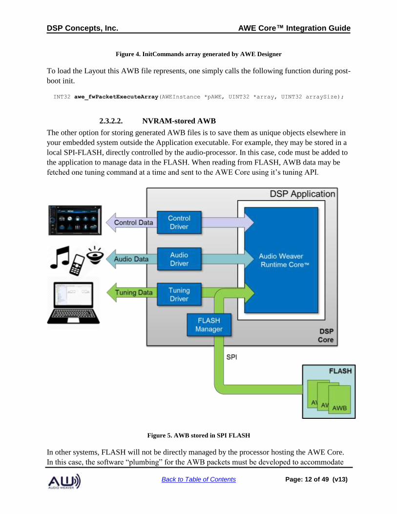
Audio Weaver Designer will automatically generate this pre-initialized array in a .C file by
selecting Tools -> Generate Target Files. An example of the resulting, generated source is
shown below in Figure 4. It shows the AWB data, stored as hex values. Details of the command
structure can be found below in section 3.4.
DSP Concepts, Inc. AWE Core™ Integration Guide
Back to Table of Contents Page: 12 of 49 (v13)
Figure 4. InitCommands array generated by AWE Designer
To load the Layout this AWB file represents, one simply calls the following function during post-
boot init.
INT32 awe_fwPacketExecuteArray(AWEInstance *pAWE, UINT32 *array, UINT32 arraySize);
2.3.2.2. NVRAM-stored AWB
The other option for storing generated AWB files is to save them as unique objects elsewhere in
your embedded system outside the Application executable. For example, they may be stored in a
local SPI-FLASH, directly controlled by the audio-processor. In this case, code must be added to
the application to manage data in the FLASH. When reading from FLASH, AWB data may be
fetched one tuning command at a time and sent to the AWE Core using it’s tuning API.
Figure 5. AWB stored in SPI FLASH
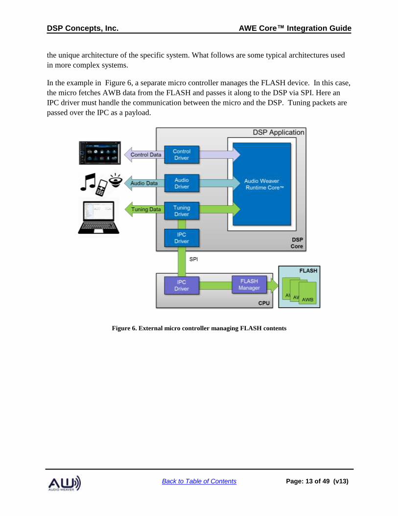
In other systems, FLASH will not be directly managed by the processor hosting the AWE Core.
In this case, the software “plumbing” for the AWB packets must be developed to accommodate
DSP Concepts, Inc. AWE Core™ Integration Guide
Back to Table of Contents Page: 13 of 49 (v13)
the unique architecture of the specific system. What follows are some typical architectures used
in more complex systems.
In the example in Figure 6, a separate micro controller manages the FLASH device. In this case,
the micro fetches AWB data from the FLASH and passes it along to the DSP via SPI. Here an
IPC driver must handle the communication between the micro and the DSP. Tuning packets are
passed over the IPC as a payload.
Figure 6. External micro controller managing FLASH contents
DSP Concepts, Inc. AWE Core™ Integration Guide
Back to Table of Contents Page: 14 of 49 (v13)
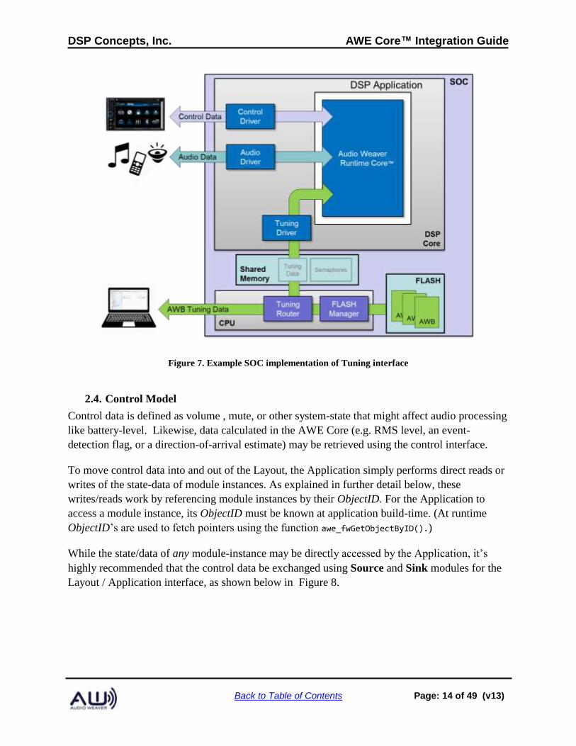
Figure 7. Example SOC implementation of Tuning interface
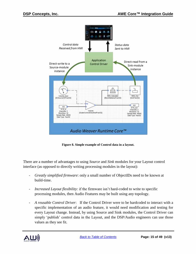
2.4. Control Model
Control data is defined as volume , mute, or other system-state that might affect audio processing
like battery-level. Likewise, data calculated in the AWE Core (e.g. RMS level, an event-
detection flag, or a direction-of-arrival estimate) may be retrieved using the control interface.
To move control data into and out of the Layout, the Application simply performs direct reads or
writes of the state-data of module instances. As explained in further detail below, these
writes/reads work by referencing module instances by their ObjectID. For the Application to
access a module instance, its ObjectID must be known at application build-time. (At runtime
ObjectID’s are used to fetch pointers using the function awe_fwGetObjectByID().)
While the state/data of any module-instance may be directly accessed by the Application, it’s
highly recommended that the control data be exchanged using Source and Sink modules for the
Layout / Application interface, as shown below in Figure 8.
DSP Concepts, Inc. AWE Core™ Integration Guide
Back to Table of Contents Page: 15 of 49 (v13)
Figure 8. Simple example of Control data in a layout.
There are a number of advantages to using Source and Sink modules for your Layout control
interface (as opposed to directly writing processing modules in the layout):
- Greatly simplified firmware: only a small number of ObjectIDs need to be known at
build-time.
- Increased Layout flexibility: if the firmware isn’t hard-coded to write to specific
processing modules, then Audio Features may be built using any topology.
- A reusable Control Driver: If the Control Driver were to be hardcoded to interact with a
specific implementation of an audio feature, it would need modification and testing for
every Layout change. Instead, by using Source and Sink modules, the Control Driver can
simply ‘publish’ control data in the Layout, and the DSP/Audio engineers can use those
values as they see fit.
DSP Concepts, Inc. AWE Core™ Integration Guide
Back to Table of Contents Page: 16 of 49 (v13)
- Increased Efficiency: The Control Driver only needs to write the control-data to the
Layout once. It can then be distributed and used throughout the Layout via control wires.
Layouts typically use one of two conventions for Source and Sink modules as a Layout control
interface. The first is to use unique Source/Sink modules for each control signal. The second is to
use a ‘multi-channel’ Source to effectively create a “control bus”. Greater detail and tradeoffs
are explained below:
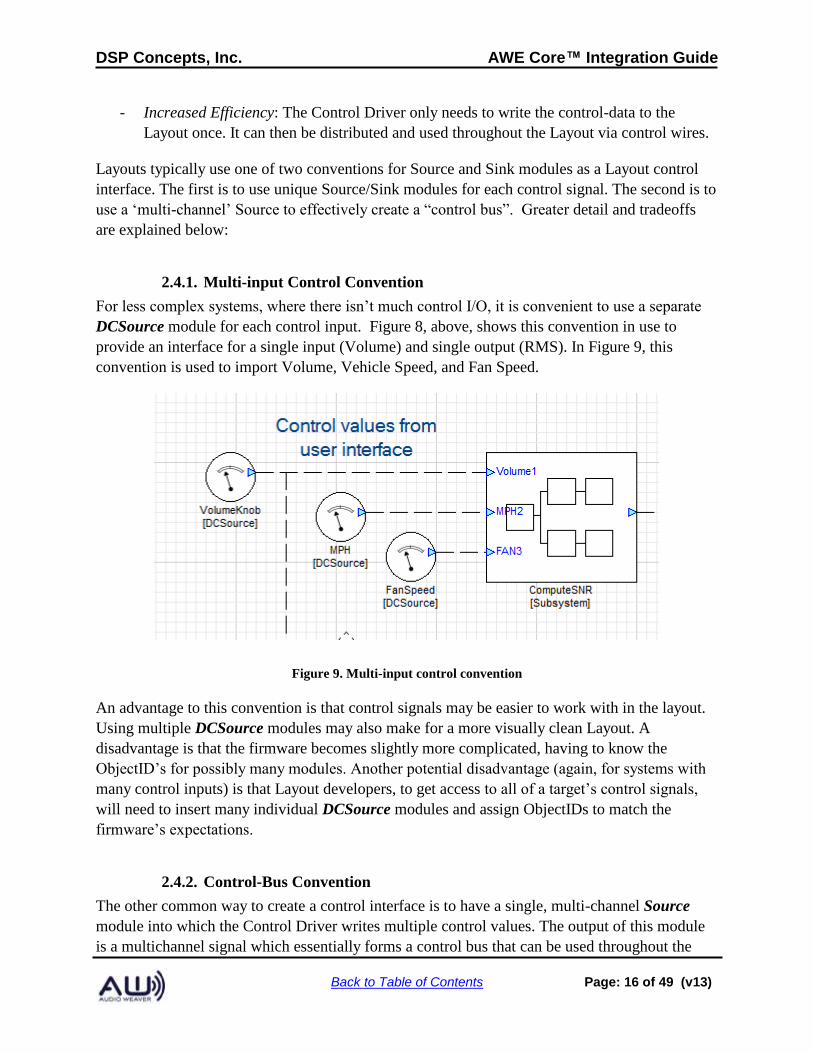
2.4.1. Multi-input Control Convention
For less complex systems, where there isn’t much control I/O, it is convenient to use a separate
DCSource module for each control input. Figure 8, above, shows this convention in use to
provide an interface for a single input (Volume) and single output (RMS). In Figure 9, this
convention is used to import Volume, Vehicle Speed, and Fan Speed.
Figure 9. Multi-input control convention
An advantage to this convention is that control signals may be easier to work with in the layout.
Using multiple DCSource modules may also make for a more visually clean Layout. A
disadvantage is that the firmware becomes slightly more complicated, having to know the
ObjectID’s for possibly many modules. Another potential disadvantage (again, for systems with
many control inputs) is that Layout developers, to get access to all of a target’s control signals,
will need to insert many individual DCSource modules and assign ObjectIDs to match the
firmware’s expectations.
2.4.2. Control-Bus Convention
The other common way to create a control interface is to have a single, multi-channel Source
module into which the Control Driver writes multiple control values. The output of this module
is a multichannel signal which essentially forms a control bus that can be used throughout the
DSP Concepts, Inc. AWE Core™ Integration Guide
Back to Table of Contents Page: 17 of 49 (v13)
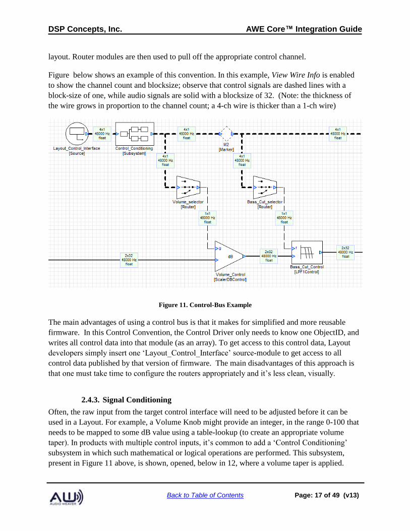
layout. Router modules are then used to pull off the appropriate control channel.
Figure below shows an example of this convention. In this example, View Wire Info is enabled
to show the channel count and blocksize; observe that control signals are dashed lines with a
block-size of one, while audio signals are solid with a blocksize of 32. (Note: the thickness of
the wire grows in proportion to the channel count; a 4-ch wire is thicker than a 1-ch wire)
Figure 11. Control-Bus Example
The main advantages of using a control bus is that it makes for simplified and more reusable
firmware. In this Control Convention, the Control Driver only needs to know one ObjectID, and
writes all control data into that module (as an array). To get access to this control data, Layout
developers simply insert one ‘Layout_Control_Interface’ source-module to get access to all
control data published by that version of firmware. The main disadvantages of this approach is
that one must take time to configure the routers appropriately and it’s less clean, visually.
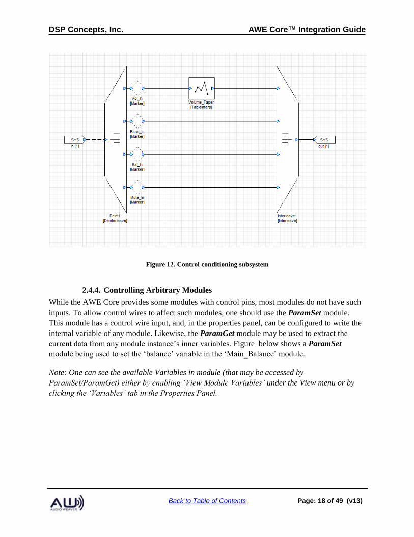
2.4.3. Signal Conditioning
Often, the raw input from the target control interface will need to be adjusted before it can be
used in a Layout. For example, a Volume Knob might provide an integer, in the range 0-100 that
needs to be mapped to some dB value using a table-lookup (to create an appropriate volume
taper). In products with multiple control inputs, it’s common to add a ‘Control Conditioning’
subsystem in which such mathematical or logical operations are performed. This subsystem,
present in Figure 11 above, is shown, opened, below in 12, where a volume taper is applied.
DSP Concepts, Inc. AWE Core™ Integration Guide
Back to Table of Contents Page: 18 of 49 (v13)
Figure 12. Control conditioning subsystem
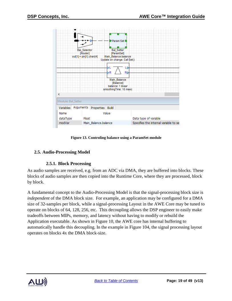
2.4.4. Controlling Arbitrary Modules
While the AWE Core provides some modules with control pins, most modules do not have such
inputs. To allow control wires to affect such modules, one should use the ParamSet module.
This module has a control wire input, and, in the properties panel, can be configured to write the
internal variable of any module. Likewise, the ParamGet module may be used to extract the
current data from any module instance’s inner variables. Figure below shows a ParamSet
module being used to set the ‘balance’ variable in the ‘Main_Balance’ module.
Note: One can see the available Variables in module (that may be accessed by
ParamSet/ParamGet) either by enabling ‘View Module Variables’ under the View menu or by
clicking the ‘Variables’ tab in the Properties Panel.
DSP Concepts, Inc. AWE Core™ Integration Guide
Back to Table of Contents Page: 19 of 49 (v13)
Figure 13. Controling balance using a ParamSet module
2.5. Audio-Processing Model
2.5.1. Block Processing
As audio samples are received, e.g. from an ADC via DMA, they are buffered into blocks. These
blocks of audio samples are then copied into the Runtime Core, where they are processed, block
by block.
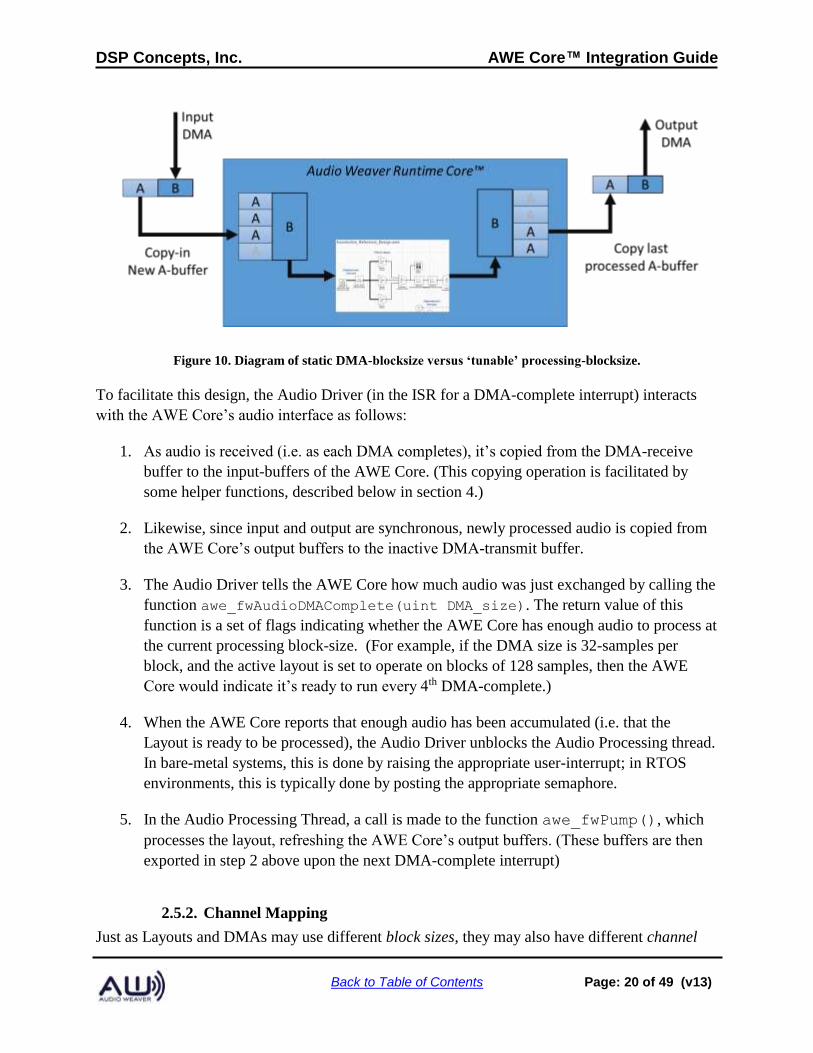
A fundamental concept to the Audio-Processing Model is that the signal-processing block size is
independent of the DMA block size. For example, an application may be configured for a DMA
size of 32-samples per block, while a signal-processing Layout in the AWE Core may be tuned to
operate on blocks of 64, 128, 256, etc. This decoupling allows the DSP engineer to easily make
tradeoffs between MIPs, memory, and latency without having to modify or rebuild the
Application executable. As shown in Figure 10, the AWE core has internal buffering to
automatically handle this decoupling. In the example in Figure 104, the signal processing layout
operates on blocks 4x the DMA block-size.
DSP Concepts, Inc. AWE Core™ Integration Guide
Back to Table of Contents Page: 20 of 49 (v13)
Figure 10. Diagram of static DMA-blocksize versus ‘tunable’ processing-blocksize.
To facilitate this design, the Audio Driver (in the ISR for a DMA-complete interrupt) interacts
with the AWE Core’s audio interface as follows:
1. As audio is received (i.e. as each DMA completes), it’s copied from the DMA-receive
buffer to the input-buffers of the AWE Core. (This copying operation is facilitated by
some helper functions, described below in section 4.)
2. Likewise, since input and output are synchronous, newly processed audio is copied from
the AWE Core’s output buffers to the inactive DMA-transmit buffer.
3. The Audio Driver tells the AWE Core how much audio was just exchanged by calling the
function awe_fwAudioDMAComplete(uint DMA_size). The return value of this
function is a set of flags indicating whether the AWE Core has enough audio to process at
the current processing block-size. (For example, if the DMA size is 32-samples per
block, and the active layout is set to operate on blocks of 128 samples, then the AWE
Core would indicate it’s ready to run every 4th DMA-complete.)
4. When the AWE Core reports that enough audio has been accumulated (i.e. that the
Layout is ready to be processed), the Audio Driver unblocks the Audio Processing thread.
In bare-metal systems, this is done by raising the appropriate user-interrupt; in RTOS
environments, this is typically done by posting the appropriate semaphore.
5. In the Audio Processing Thread, a call is made to the function awe_fwPump(), which
processes the layout, refreshing the AWE Core’s output buffers. (These buffers are then
exported in step 2 above upon the next DMA-complete interrupt)
2.5.2. Channel Mapping
Just as Layouts and DMAs may use different block sizes, they may also have different channel
DSP Concepts, Inc. AWE Core™ Integration Guide
Back to Table of Contents Page: 21 of 49 (v13)
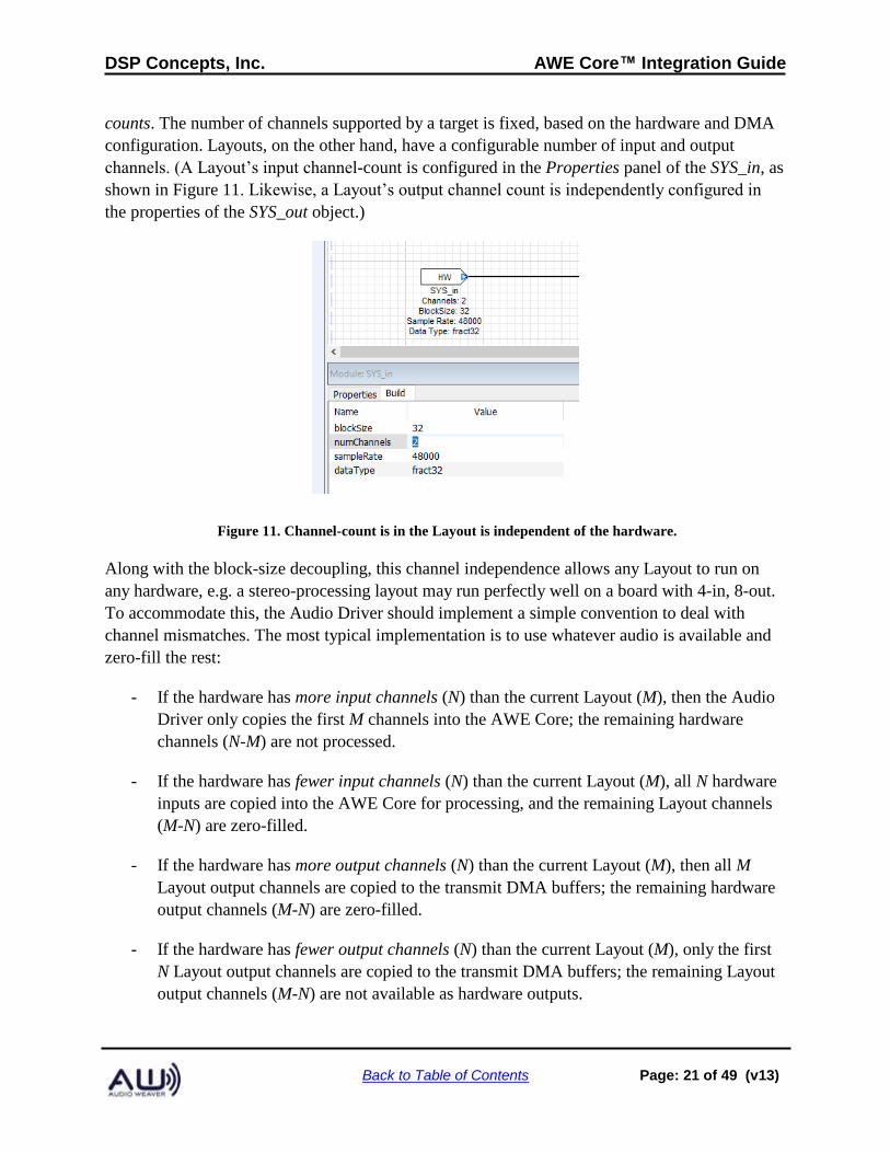
counts. The number of channels supported by a target is fixed, based on the hardware and DMA
configuration. Layouts, on the other hand, have a configurable number of input and output
channels. (A Layout’s input channel-count is configured in the Properties panel of the SYS_in, as
shown in Figure 11. Likewise, a Layout’s output channel count is independently configured in
the properties of the SYS_out object.)
Figure 11. Channel-count is in the Layout is independent of the hardware.
Along with the block-size decoupling, this channel independence allows any Layout to run on
any hardware, e.g. a stereo-processing layout may run perfectly well on a board with 4-in, 8-out.
To accommodate this, the Audio Driver should implement a simple convention to deal with
channel mismatches. The most typical implementation is to use whatever audio is available and
zero-fill the rest:
- If the hardware has more input channels (N) than the current Layout (M), then the Audio
Driver only copies the first M channels into the AWE Core; the remaining hardware
channels (N-M) are not processed.
- If the hardware has fewer input channels (N) than the current Layout (M), all N hardware
inputs are copied into the AWE Core for processing, and the remaining Layout channels
(M-N) are zero-filled.
- If the hardware has more output channels (N) than the current Layout (M), then all M
Layout output channels are copied to the transmit DMA buffers; the remaining hardware
output channels (M-N) are zero-filled.
- If the hardware has fewer output channels (N) than the current Layout (M), only the first
N Layout output channels are copied to the transmit DMA buffers; the remaining Layout
output channels (M-N) are not available as hardware outputs.
DSP Concepts, Inc. AWE Core™ Integration Guide
Back to Table of Contents Page: 22 of 49 (v13)
2.6. Threading / Priority Model
All threading and interrupt issues are managed outside of the AWE Core by the Application.
This approach allows Audio Weaver to run in virtually any embedded environment, from
lightweight targets running bare-metal to more sophisticated systems with an RTOS.
2.6.1. Basic Threading Model
A basic Audio Weaver platform has 4 threads. From highest priority to lowest priority, the
threads are arranged as:
• Audio I/O – Blocks of Audio Data are exchanged between DMA-buffers and the AWE
Core’s input and output buffers. Note: Audio is not processed in this thread; it’s simply
copied into and out of the AWE Core.
• Tuning I/O – Tuning Data, on a byte, word, or packet boundary is exchanged between
the Tuning Driver and the AWE core. Note: Tuning data is not processed in this thread;
it’s simply moved into and out of the AWE Core.
• Audio Processing – In this thread, the active Layout is processed. This thread is raised /
unblocked by the Audio I/O thread when sufficient audio data has been received.
• Background Processing – In the background / main() thread, non-real-time tasks are
processed. The AWE Core has a single function that must be called from this context:
awe_fwTick(); This function handles all background tasks in AWE Core, including,
among other things, the processing of tuning commands.
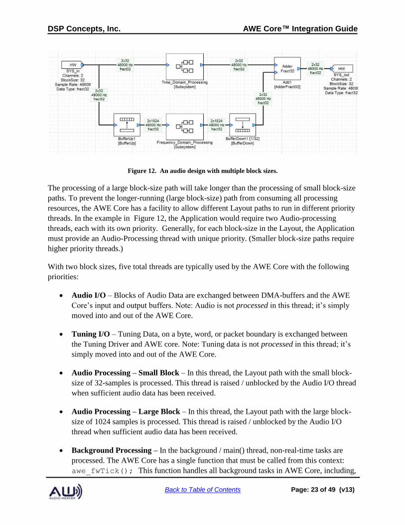
2.6.2. Advanced Threading Model
The AWE Core allows audio to be processed at multiple block sizes. For example, one path
through the layout might do time-domain processing on a block size of 32 samples while another
path through the Layout does frequency-domain processing on blocks of 1024 samples. A
system like this is built using the BufferUp and BufferDown modules in the layout to connect the
different block size domains as shown in Figure 12.
DSP Concepts, Inc. AWE Core™ Integration Guide
Back to Table of Contents Page: 23 of 49 (v13)
Figure 12. An audio design with multiple block sizes.
The processing of a large block-size path will take longer than the processing of small block-size
paths. To prevent the longer-running (large block-size) path from consuming all processing
resources, the AWE Core has a facility to allow different Layout paths to run in different priority
threads. In the example in Figure 12, the Application would require two Audio-processing
threads, each with its own priority. Generally, for each block-size in the Layout, the Application
must provide an Audio-Processing thread with unique priority. (Smaller block-size paths require
higher priority threads.)
With two block sizes, five total threads are typically used by the AWE Core with the following
priorities:
• Audio I/O – Blocks of Audio Data are exchanged between DMA-buffers and the AWE
Core’s input and output buffers. Note: Audio is not processed in this thread; it’s simply
moved into and out of the AWE Core.
• Tuning I/O – Tuning Data, on a byte, word, or packet boundary is exchanged between
the Tuning Driver and AWE core. Note: Tuning data is not processed in this thread; it’s
simply moved into and out of the AWE Core.
• Audio Processing – Small Block – In this thread, the Layout path with the small block-
size of 32-samples is processed. This thread is raised / unblocked by the Audio I/O thread
when sufficient audio data has been received.
• Audio Processing – Large Block – In this thread, the Layout path with the large block-
size of 1024 samples is processed. This thread is raised / unblocked by the Audio I/O
thread when sufficient audio data has been received.
• Background Processing – In the background / main() thread, non-real-time tasks are
processed. The AWE Core has a single function that must be called from this context:
awe_fwTick(); This function handles all background tasks in AWE Core, including,
DSP Concepts, Inc. AWE Core™ Integration Guide
Back to Table of Contents Page: 24 of 49 (v13)
among other things, the processing of tuning commands.
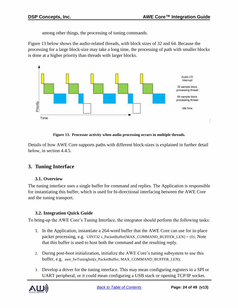
Figure 13 below shows the audio-related threads, with block sizes of 32 and 64. Because the
processing for a large block-size may take a long time, the processing of path with smaller blocks
is done at a higher priority than threads with larger blocks.
Figure 13. Processor activity when audio processing occurs in multiple threads.
Details of how AWE Core supports paths with different block-sizes is explained in further detail
below, in section 4.4.5.
3. Tuning Interface
3.1. Overview
The tuning interface uses a single buffer for command and replies. The Application is responsible
for instantiating this buffer, which is used for bi-directional interfacing between the AWE Core
and the tuning transport.
3.2. Integration Quick Guide
To bring-up the AWE Core’s Tuning Interface, the integrator should perform the following tasks:
1. In the Application, instantiate a 264-word buffer that the AWE Core can use for in-place
packet processing, e.g. UINT32 s_PacketBuffer[MAX_COMMAND_BUFFER_LEN] = {0}; Note
that this buffer is used to host both the command and the resulting reply.
2. During post-boot initialization, initialize the AWE Core’s tuning subsystem to use this
buffer, e.g. awe_fwTuningInit(s_PacketBuffer, MAX_COMMAND_BUFFER_LEN);
3. Develop a driver for the tuning interface. This may mean configuring registers in a SPI or
UART peripheral, or it could mean configuring a USB stack or opening TCP/IP socket.
DSP Concepts, Inc. AWE Core™ Integration Guide
Back to Table of Contents Page: 25 of 49 (v13)
4. Create a high-priority “Tuning I/O thread” to handle data from the tuning transport (e.g.
UART, USB, etc.).
5. Verify driver, protocol, and hardware functionality by implementing simple ‘echo-back’
functionality. In this step, simply copy all received data back to the transmit buffer.
6. Modify the “Tuning I/O thread” to send received into the AWE core using whichever
method is most convenient: awe_fwTuningRxByte(), awe_fwTuningRxWord(), or
awe_fwTuningRxPacket(). Note: tuning commands are not processed in this thread.
7. In the background thread, add repeated calls awe_fwTuningTick() to continually process
data as it arrives. This function will execute commands (once they’re fully received), and
will return REPLY_READY when a reply packet has been generated.
8. Develop a method to send the reply packet back over the tuning transport. The reply will
always reside in the tuning buffer allocated in step one. As shown below in section 3.4,
the length of the reply (in words) is in the upper 16-bits of the 32-bit header.
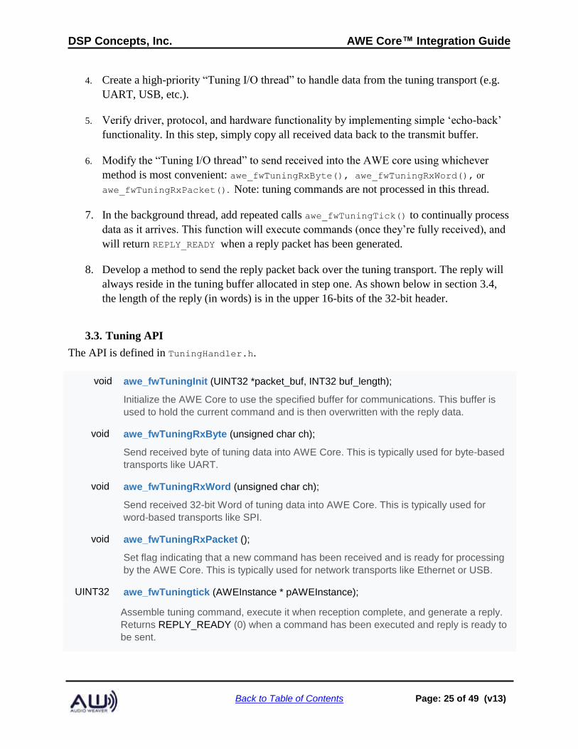
3.3. Tuning API
The API is defined in TuningHandler.h.
void awe_fwTuningInit (UINT32 *packet_buf, INT32 buf_length);
Initialize the AWE Core to use the specified buffer for communications. This buffer is
used to hold the current command and is then overwritten with the reply data.
void awe_fwTuningRxByte (unsigned char ch);
Send received byte of tuning data into AWE Core. This is typically used for byte-based
transports like UART.
void awe_fwTuningRxWord (unsigned char ch);
Send received 32-bit Word of tuning data into AWE Core. This is typically used for
word-based transports like SPI.
void awe_fwTuningRxPacket ();
Set flag indicating that a new command has been received and is ready for processing
by the AWE Core. This is typically used for network transports like Ethernet or USB.
UINT32 awe_fwTuningtick (AWEInstance * pAWEInstance);
Assemble tuning command, execute it when reception complete, and generate a reply.
Returns REPLY_READY (0) when a command has been executed and reply is ready to
be sent.
DSP Concepts, Inc. AWE Core™ Integration Guide
Back to Table of Contents Page: 26 of 49 (v13)
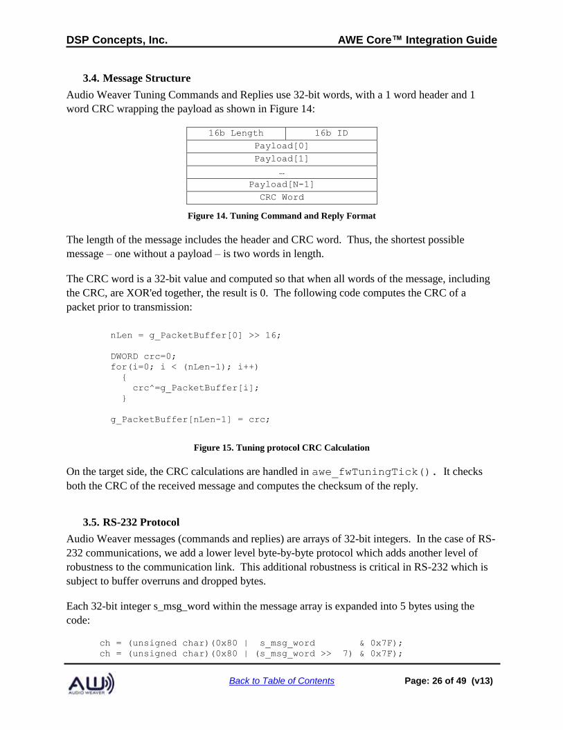
3.4. Message Structure
Audio Weaver Tuning Commands and Replies use 32-bit words, with a 1 word header and 1
word CRC wrapping the payload as shown in Figure 14:
16b Length 16b ID
Payload[0]
Payload[1]
…
Payload[N-1]
CRC Word
Figure 14. Tuning Command and Reply Format
The length of the message includes the header and CRC word. Thus, the shortest possible
message – one without a payload – is two words in length.
The CRC word is a 32-bit value and computed so that when all words of the message, including
the CRC, are XOR'ed together, the result is 0. The following code computes the CRC of a
packet prior to transmission:
nLen = g_PacketBuffer[0] >> 16;
DWORD crc=0;
for(i=0; i < (nLen-1); i++)
{
crc^=g_PacketBuffer[i];
}
g_PacketBuffer[nLen-1] = crc;
Figure 15. Tuning protocol CRC Calculation
On the target side, the CRC calculations are handled in awe_fwTuningTick(). It checks
both the CRC of the received message and computes the checksum of the reply.
3.5. RS-232 Protocol
Audio Weaver messages (commands and replies) are arrays of 32-bit integers. In the case of RS-
232 communications, we add a lower level byte-by-byte protocol which adds another level of
robustness to the communication link. This additional robustness is critical in RS-232 which is
subject to buffer overruns and dropped bytes.
Each 32-bit integer s_msg_word within the message array is expanded into 5 bytes using the
code:
ch = (unsigned char)(0x80 | s_msg_word & 0x7F);
ch = (unsigned char)(0x80 | (s_msg_word >> 7) & 0x7F);
DSP Concepts, Inc. AWE Core™ Integration Guide
Back to Table of Contents Page: 27 of 49 (v13)
ch = (unsigned char)(0x80 | (s_msg_word >> 14) & 0x7F);
ch = (unsigned char)(0x80 | (s_msg_word >> 21) & 0x7F);
ch = (unsigned char)(0x80 | (s_msg_word >> 28) & 0x7F);
7 data bits are taken at a time from each message word and the high bit is set. (For the last
character, only the low 4 data bits are used.)
The data is then encapsulated within a series of protocol bytes:
Start Byte 0x02
Sequence Byte 0x30 to 0x39 (ASCII “0” to “9”)
Message Bytes 0x80 to 0xFF. 5 bytes at a time.
Stop Byte 0x03
With this design, the protocol bytes are unique. That is, the protocol bytes (0x02, 0x03, 0x30-
0x39) are never found within the data bytes since the data bytes always have the high bit set.
This makes it easy to identify the start and end of data packets. The sequence byte starts at 0x30,
increments 1 for each successful transmission, and then wraps from 0x39 to 0x30. The sequence
byte is used to identify retransmissions.
For example, consider the command PFID_GetProfileValues with ID = 43. The message sent
from the PC to the target processor is:
Message Length = 2 ID = PFID_GetProfileValue
CRC
Which translates into the 32-bit words:
0x0002002b
0x0002002b (CRC is the same for 1 word payloads)
The 32-bit words are expanded into 5 bytes each:
0x0002002b → 0xAB 0x80 0x88 0x80 0x80
0x0002002b → 0xAB 0x80 0x88 0x80 0x80
Adding the remaining protocol bytes, the sequence sent is:
0x02 (start byte)
0x3X (sequence)
0xAB 0x80 0x88 0x80 0x80 (payload)
0xAB 0x80 0x88 0x80 0x80 (CRC)
DSP Concepts, Inc. AWE Core™ Integration Guide
Back to Table of Contents Page: 28 of 49 (v13)
0x03
3.6. SPI Protocol
The Audio Weaver SPI protocol mirrors the 32-bit packet structure. There are two differences:
1. The 32-bit synchronization word 0xDEADBEEF is sent before each message.
2. The 4 bytes within each 32-bit word as swapped. 0x12345678 it turned into 0x78563412.
For example, consider the command “PFID_GetProfileValues” with ID = 43 (0x2b). The
message sent from the PC to the target processor is:
Message Length = 2 ID = PFID_GetProfileValue
CRC
This translates into the 32-bit words:
0x0002002b
0x0002002b (CRC is the same for 1 word payloads)
The overall message sent is:
0xDEADBEEF → 0xEFBEADDE
0x0002002B → 0x2B000200
0x0002002B → 0x2B000200
After a message is received by the target processor and the message is being processed, the SPI
output buffer will be set to the “not ready” word 0xA3A3A3A3. This will allow a host processor
to poll the SPI interface waiting for the target processor to complete message processing. The
target processor will continue to transmit the not ready word until the message has been
processed. At this point, it will switch over to the sync word followed by the complete message.
If the host processor continues to read beyond the end of a reply from the target, then the target
will return 0xFFFFFFFF.
DSP Concepts, Inc. AWE Core™ Integration Guide
Back to Table of Contents Page: 29 of 49 (v13)
3.7. USB Protocol
Audio weaver USB communication is based on the USB HID protocol. Audio Weaver
commands and replies are encapsulated in one or more 56-byte HID report packets operating
over a 64-byte USB pipe. Each HID report packet starts with the HID report ID. Audio Weaver
uses HID Report ID 1. If USB HID communications are used for other firmware features, those
features must use a HID Report ID other than 1.
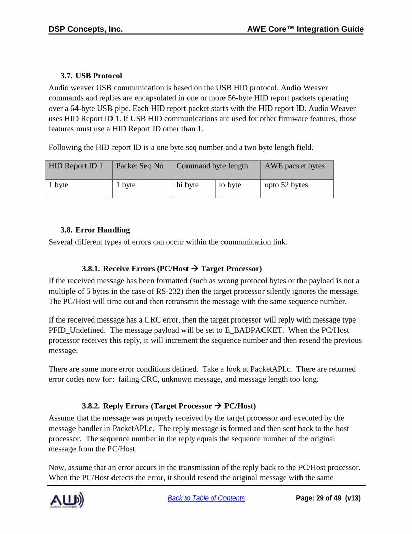
Following the HID report ID is a one byte seq number and a two byte length field.
HID Report ID 1 Packet Seq No Command byte length AWE packet bytes
1 byte 1 byte hi byte lo byte upto 52 bytes
3.8. Error Handling
Several different types of errors can occur within the communication link.
3.8.1. Receive Errors (PC/Host → Target Processor)
If the received message has been formatted (such as wrong protocol bytes or the payload is not a
multiple of 5 bytes in the case of RS-232) then the target processor silently ignores the message.
The PC/Host will time out and then retransmit the message with the same sequence number.
If the received message has a CRC error, then the target processor will reply with message type
PFID_Undefined. The message payload will be set to E_BADPACKET. When the PC/Host
processor receives this reply, it will increment the sequence number and then resend the previous
message.
There are some more error conditions defined. Take a look at PacketAPI.c. There are returned
error codes now for: failing CRC, unknown message, and message length too long.
3.8.2. Reply Errors (Target Processor → PC/Host)
Assume that the message was properly received by the target processor and executed by the
message handler in PacketAPI.c. The reply message is formed and then sent back to the host
processor. The sequence number in the reply equals the sequence number of the original
message from the PC/Host.
Now, assume that an error occurs in the transmission of the reply back to the PC/Host processor.
When the PC/Host detects the error, it should resend the original message with the same
DSP Concepts, Inc. AWE Core™ Integration Guide
Back to Table of Contents Page: 30 of 49 (v13)
sequence number. When the message is received by the target processor, the target processor
sees that the sequence number is unchanged from the last message; this flags an error in the
previous reply. The target processor does not re-execute the last command. Instead, it simply
sends the reply again.
Once a message is received through the tuning interface, it is processed by in the function
awe_fwTick(). The first step is to check the CRC. If there is a CRC error, the target processor
returns a 3 word message to the host (PC). The message type is:
PFID_Undefined
and the message payload is
E_BADPACKET
When this error is received by the host (PC) the last message should be retransmitted.
The Audio Weaver Server application does extensive error handling on the received data. If an
error occurs, the Server retransmits the packet 3 times before hard failing.
3.8.3. Time Outs and Resends
The Audio Weaver has several configurable timeouts. After a message is sent to the target
processor the Server waits for a reply. When using the RS232 protocol, if the start of the reply is
not received within 50 msec the Server declares a time out and resends the message
(SingleCharTimeout). If the entire reply is not received within 150 msec then a timeout is
declared (TotalTimeoutTimeout).
When a timeout occurs, the Server resends the message. If the same message has been sent 3
times (2 timeouts), then the Server will declare an error and inform the user.
The timeout periods can be modified to match your application. Edit the AWE_Server.ini file
and add the lines:
[TimeOut]
SingleCharTimeout=200
TotalTimeoutTimeout=1000
All times are in milliseconds.
4. Audio Interface
4.1. Overview
Audio I/O takes place outside of the AWE Core, in the high-priority Audio I/O Thread. In this

DSP Concepts, Inc. AWE Core™ Integration Guide
Back to Table of Contents Page: 31 of 49 (v13)
thread, audio-samples are buffered up into blocks and then passed into Audio Weaver. In typical
implementations, audio I/O uses ping-pong buffers and DMA, as shown in Figure 16. The
block-size of the DMA operation is called the fundamentalBlockSize and is typically 32 samples.
The AWE Core has additional internal buffering which allows processing to run at any multiple
of the fundamentalBlockSize.
Figure 16. Block based audio processing using double buffered DMA.
The Application is responsible for all DMA setup and buffering, including configuring the audio
codec, DMA, and managing interrupts. This section describes how audio data is exchanged with
and processed by the AWE Core.
4.2. Audio Processing
The Audio Interface is typically the second thing in a system to be brought up during integration
(after the Tuning Interface). To bring-up the AWE Core’s Audio Interface, the integrator should
perform the following tasks:
1. In the Application, instantiate DMA buffers for input and output.
2. During post-boot initialization, initialize the AWE Core’s audio subsystem using awe_fwInit();
3. Develop a driver for the audio interface. This may mean configuring a TDM or I2S
Serial-Port peripheral, A2B interface, or Shared-Memory IPC system.
4. Configure ‘chained’ Receive and Transmit DMAs.
5. Implement a basic high-priority “Audio I/O thread” (the ISR for a DMA-complete
interrupt in a bare-metal system) with ‘DMA pass-through’ functionality. The goal of this
step is to ensure that the rest of the Audio path (drivers, CODECs, network transceivers,
amplifiers, etc) is functional by simply copying from the DMA-receive buffer to the
DMA-transmit buffer.
DSP Concepts, Inc. AWE Core™ Integration Guide
Back to Table of Contents Page: 32 of 49 (v13)
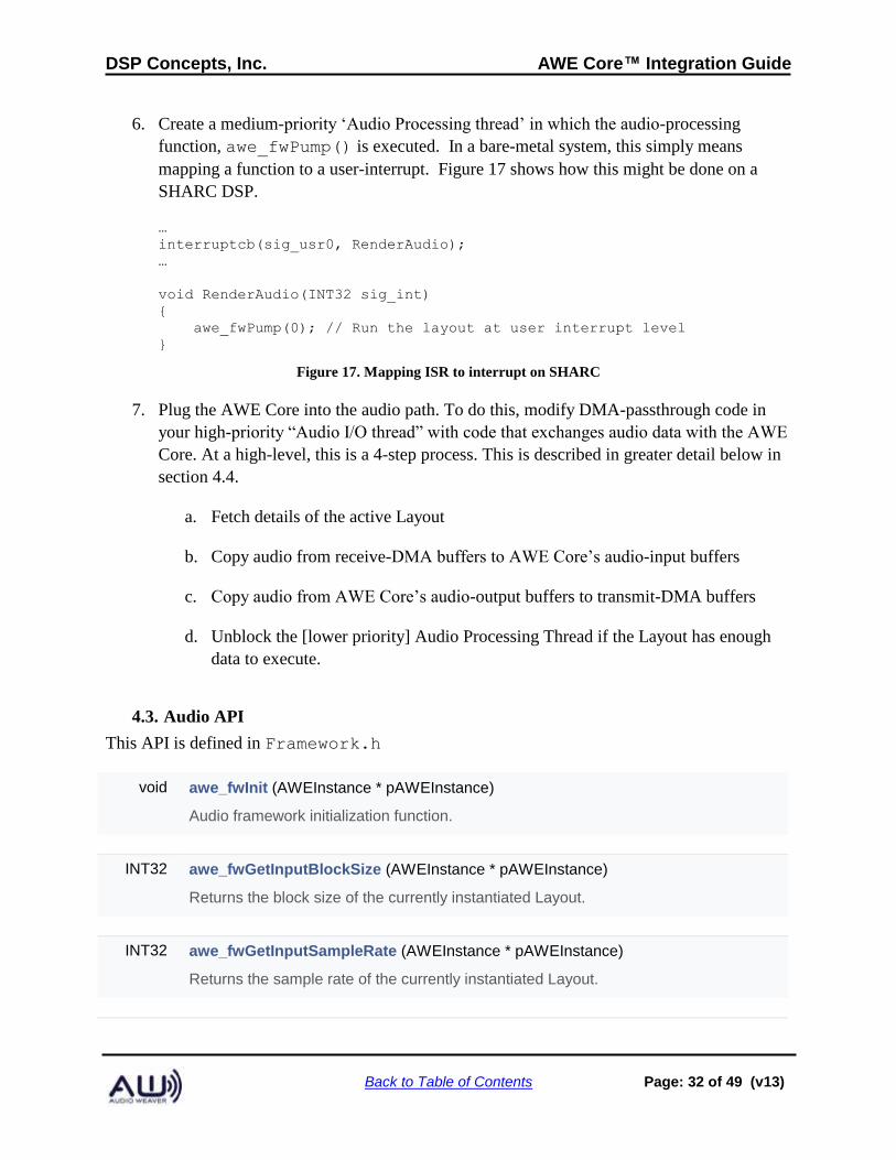
6. Create a medium-priority ‘Audio Processing thread’ in which the audio-processing
function, awe_fwPump() is executed. In a bare-metal system, this simply means
mapping a function to a user-interrupt. Figure 17 shows how this might be done on a
SHARC DSP.
…
interruptcb(sig_usr0, RenderAudio);
…
void RenderAudio(INT32 sig_int)
{
awe_fwPump(0); // Run the layout at user interrupt level
}
Figure 17. Mapping ISR to interrupt on SHARC
7. Plug the AWE Core into the audio path. To do this, modify DMA-passthrough code in
your high-priority “Audio I/O thread” with code that exchanges audio data with the AWE
Core. At a high-level, this is a 4-step process. This is described in greater detail below in
section 4.4.
a. Fetch details of the active Layout
b. Copy audio from receive-DMA buffers to AWE Core’s audio-input buffers
c. Copy audio from AWE Core’s audio-output buffers to transmit-DMA buffers
d. Unblock the [lower priority] Audio Processing Thread if the Layout has enough
data to execute.
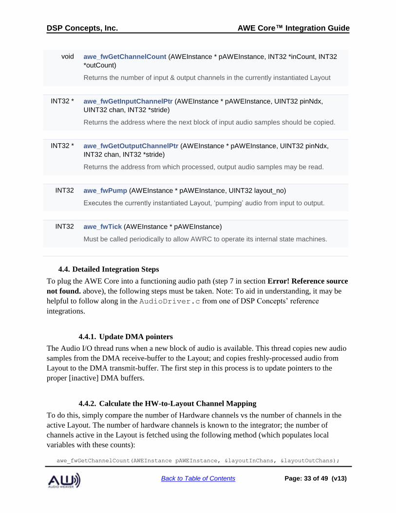
4.3. Audio API
This API is defined in Framework.h
void awe_fwInit (AWEInstance * pAWEInstance)
Audio framework initialization function.
INT32 awe_fwGetInputBlockSize (AWEInstance * pAWEInstance)
Returns the block size of the currently instantiated Layout.
INT32 awe_fwGetInputSampleRate (AWEInstance * pAWEInstance)
Returns the sample rate of the currently instantiated Layout.
DSP Concepts, Inc. AWE Core™ Integration Guide
Back to Table of Contents Page: 33 of 49 (v13)
void awe_fwGetChannelCount (AWEInstance * pAWEInstance, INT32 *inCount, INT32
*outCount)
Returns the number of input & output channels in the currently instantiated Layout
INT32 * awe_fwGetInputChannelPtr (AWEInstance * pAWEInstance, UINT32 pinNdx,
UINT32 chan, INT32 *stride)
Returns the address where the next block of input audio samples should be copied.
INT32 * awe_fwGetOutputChannelPtr (AWEInstance * pAWEInstance, UINT32 pinNdx,
INT32 chan, INT32 *stride)
Returns the address from which processed, output audio samples may be read.
INT32 awe_fwPump (AWEInstance * pAWEInstance, UINT32 layout_no)
Executes the currently instantiated Layout, ‘pumping’ audio from input to output.
INT32 awe_fwTick (AWEInstance * pAWEInstance)
Must be called periodically to allow AWRC to operate its internal state machines.
4.4. Detailed Integration Steps
To plug the AWE Core into a functioning audio path (step 7 in section Error! Reference source
not found. above), the following steps must be taken. Note: To aid in understanding, it may be
helpful to follow along in the AudioDriver.c from one of DSP Concepts’ reference
integrations.
4.4.1. Update DMA pointers
The Audio I/O thread runs when a new block of audio is available. This thread copies new audio
samples from the DMA receive-buffer to the Layout; and copies freshly-processed audio from
Layout to the DMA transmit-buffer. The first step in this process is to update pointers to the
proper [inactive] DMA buffers.
4.4.2. Calculate the HW-to-Layout Channel Mapping
To do this, simply compare the number of Hardware channels vs the number of channels in the
active Layout. The number of hardware channels is known to the integrator; the number of
channels active in the Layout is fetched using the following method (which populates local
variables with these counts):
awe_fwGetChannelCount(AWEInstance pAWEInstance, &layoutInChans, &layoutOutChans);
DSP Concepts, Inc. AWE Core™ Integration Guide
Back to Table of Contents Page: 34 of 49 (v13)
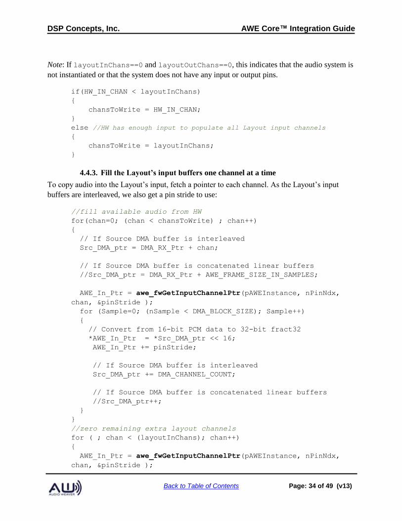
Note: If layoutInChans==0 and layoutOutChans==0, this indicates that the audio system is
not instantiated or that the system does not have any input or output pins.
if(HW_IN_CHAN < layoutInChans)
{
chansToWrite = HW_IN_CHAN;
}
else //HW has enough input to populate all Layout input channels
{
chansToWrite = layoutInChans;
}
4.4.3. Fill the Layout’s input buffers one channel at a time
To copy audio into the Layout’s input, fetch a pointer to each channel. As the Layout’s input
buffers are interleaved, we also get a pin stride to use:
//fill available audio from HW
for(chan=0; (chan < chansToWrite) ; chan++)
{
// If Source DMA buffer is interleaved
Src_DMA_ptr = DMA_RX_Ptr + chan;
// If Source DMA buffer is concatenated linear buffers
//Src_DMA_ptr = DMA_RX_Ptr + AWE_FRAME_SIZE_IN_SAMPLES;
AWE_In_Ptr = awe_fwGetInputChannelPtr(pAWEInstance, nPinNdx,
chan, &pinStride );
for (Sample=0; (nSample < DMA_BLOCK_SIZE); Sample++)
{
// Convert from 16-bit PCM data to 32-bit fract32
*AWE_In_Ptr = *Src_DMA_ptr << 16;
AWE_In_Ptr += pinStride;
// If Source DMA buffer is interleaved
Src_DMA_ptr += DMA_CHANNEL_COUNT;
// If Source DMA buffer is concatenated linear buffers
//Src_DMA_ptr++;
}
}
//zero remaining extra layout channels
for ( ; chan < (layoutInChans); chan++)
{
AWE_In_Ptr = awe_fwGetInputChannelPtr(pAWEInstance, nPinNdx,
chan, &pinStride );
DSP Concepts, Inc. AWE Core™ Integration Guide
Back to Table of Contents Page: 35 of 49 (v13)
for(Sample=0; Sample<FW_BLOCK_SIZE; Sample++)
{
AWE_In_Ptr[Sample * pinStride] = 0;
}
}
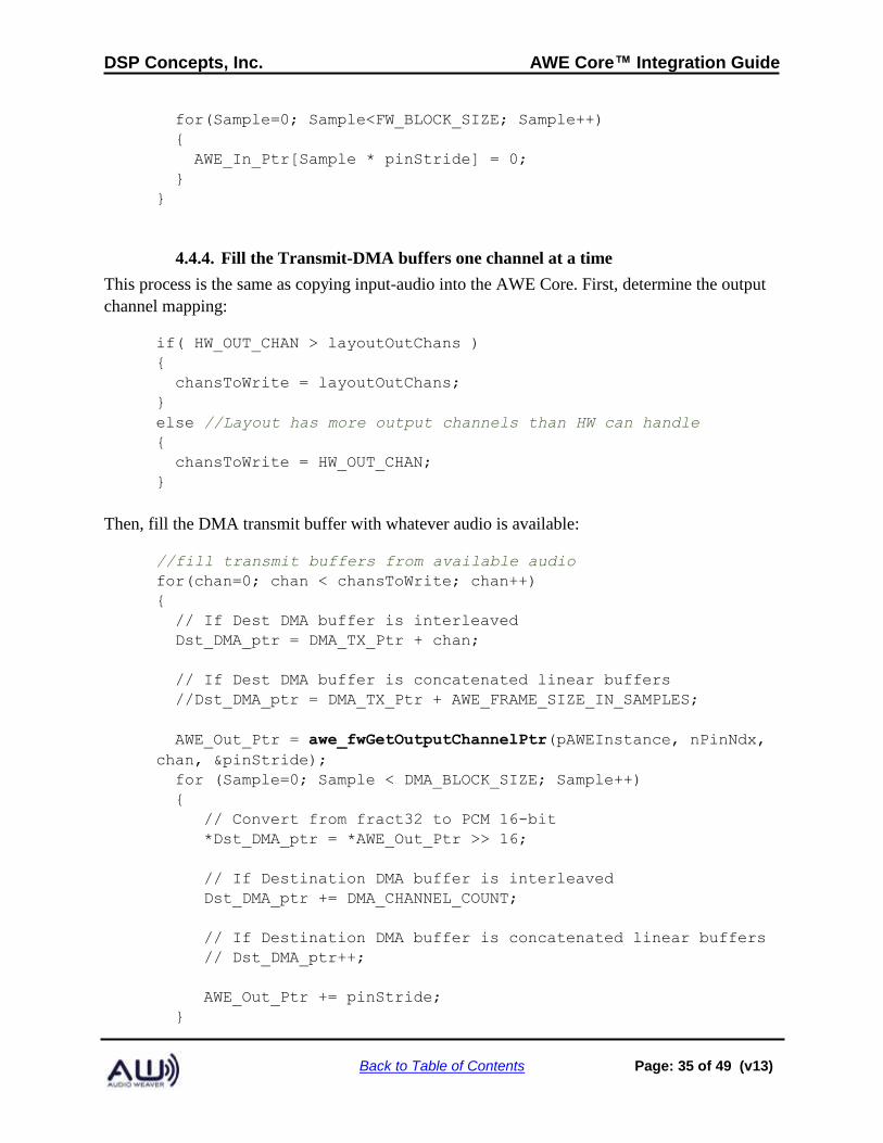
4.4.4. Fill the Transmit-DMA buffers one channel at a time
This process is the same as copying input-audio into the AWE Core. First, determine the output
channel mapping:
if( HW_OUT_CHAN > layoutOutChans )
{
chansToWrite = layoutOutChans;
}
else //Layout has more output channels than HW can handle
{
chansToWrite = HW_OUT_CHAN;
}
Then, fill the DMA transmit buffer with whatever audio is available:
//fill transmit buffers from available audio
for(chan=0; chan < chansToWrite; chan++)
{
// If Dest DMA buffer is interleaved
Dst_DMA_ptr = DMA_TX_Ptr + chan;
// If Dest DMA buffer is concatenated linear buffers
//Dst_DMA_ptr = DMA_TX_Ptr + AWE_FRAME_SIZE_IN_SAMPLES;
AWE_Out_Ptr = awe_fwGetOutputChannelPtr(pAWEInstance, nPinNdx,
chan, &pinStride);
for (Sample=0; Sample < DMA_BLOCK_SIZE; Sample++)
{
// Convert from fract32 to PCM 16-bit
*Dst_DMA_ptr = *AWE_Out_Ptr >> 16;
// If Destination DMA buffer is interleaved
Dst_DMA_ptr += DMA_CHANNEL_COUNT;
// If Destination DMA buffer is concatenated linear buffers
// Dst_DMA_ptr++;
AWE_Out_Ptr += pinStride;
}
DSP Concepts, Inc. AWE Core™ Integration Guide
Back to Table of Contents Page: 36 of 49 (v13)
}
//zero remaining extra layout channels
for ( ; chan < (layoutInChans); chan++)
{
// If Dest DMA buffer is interleaved
Dst_DMA_ptr = DMA_TX_Ptr + chan;
// If Dest DMA buffer is concatenated linear buffers
//Dst_DMA_ptr = DMA_TX_Ptr + AWE_FRAME_SIZE_IN_SAMPLES;
AWE_Out_Ptr = awe_fwGetOutputChannelPtr(pAWEInstance, nPinNdx,
chan, &pinStride);
for(samp=0;samp<FW_BLOCK_SIZE;samp++)
{
*Dst_DMA_ptr = 0;
// If Destination DMA buffer is interleaved
Dst_DMA_ptr += DMA_CHANNEL_COUNT;
// If Destination DMA buffer is concatenated linear buffers
// Dst_DMA_ptr++;
}
}
4.4.5. Tell the AWE Core how many samples were added / consumed
After handling the audio exchange between the DMA buffers and the AWE Core, we inform the
AWE core how many samples were exchanged using the following function:
unsigned int awe_fwAudioDMAComplete(AWEInstance pAWEInstance, int sampsPerTick);
The return value from this function indicates if any paths through the layout are now ready to run.
(For an explanation of this, see section 2.5.1, Block Processing and Section 2.6.2 Advanced
Threading Model)
4.4.6. Unblock the Audio Processing Thread(s) when appropriate
The return value from awe_fwAudioDMAComplete is a bit-field indicating when Layout paths
are ready to run. Bit 0 being set true means the smallest block-size (that of the input and output
pins) is ready to be processed. Bit 1 means the next larger block-size is ready to be processed,
etc.
In a bare-metal system, where thread priorities are managed using user-interrupts, this step is
done by raising the appropriate interrupt as follows:
LayoutMask = awe_fwAudioDMAComplete(pAWEInstance, FW_BLOCK_SIZE);
DSP Concepts, Inc. AWE Core™ Integration Guide
Back to Table of Contents Page: 37 of 49 (v13)
if (layoutMask & 0x01) //hi prio (small block) path ready
{
raise(SIG_USR0);
}
if (layoutMask & 0x02) //lo prio (large block) path ready
{
raise(SIG_USR1);
}
5. Control Interface
5.1. Overview
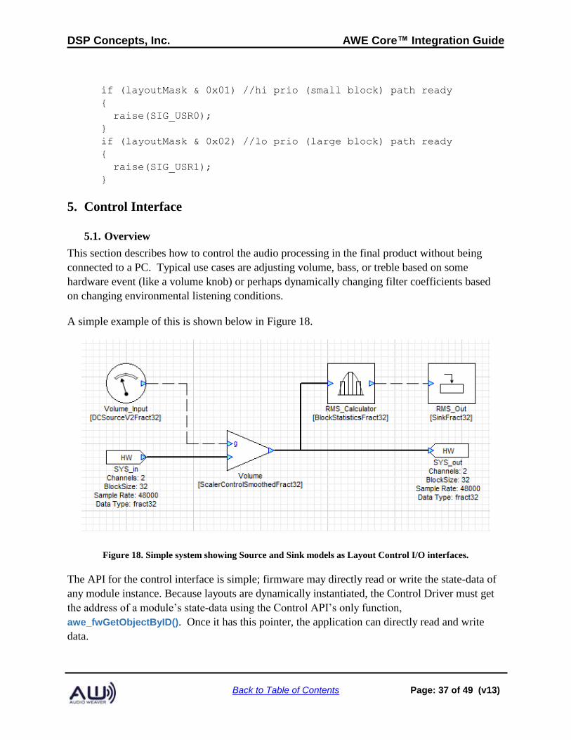
This section describes how to control the audio processing in the final product without being
connected to a PC. Typical use cases are adjusting volume, bass, or treble based on some
hardware event (like a volume knob) or perhaps dynamically changing filter coefficients based
on changing environmental listening conditions.
A simple example of this is shown below in Figure 18.
Figure 18. Simple system showing Source and Sink models as Layout Control I/O interfaces.
The API for the control interface is simple; firmware may directly read or write the state-data of
any module instance. Because layouts are dynamically instantiated, the Control Driver must get
the address of a module’s state-data using the Control API’s only function,
awe_fwGetObjectByID(). Once it has this pointer, the application can directly read and write
data.
DSP Concepts, Inc. AWE Core™ Integration Guide
Back to Table of Contents Page: 38 of 49 (v13)
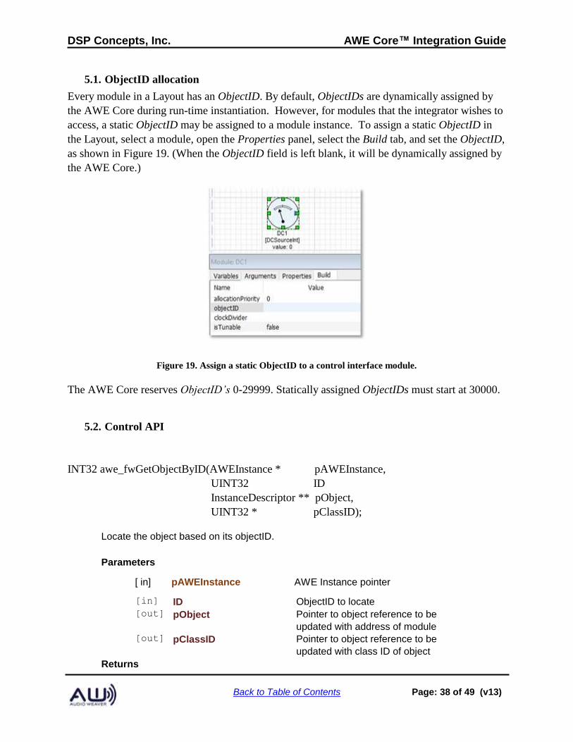
5.1. ObjectID allocation
Every module in a Layout has an ObjectID. By default, ObjectIDs are dynamically assigned by
the AWE Core during run-time instantiation. However, for modules that the integrator wishes to
access, a static ObjectID may be assigned to a module instance. To assign a static ObjectID in
the Layout, select a module, open the Properties panel, select the Build tab, and set the ObjectID,
as shown in Figure 19. (When the ObjectID field is left blank, it will be dynamically assigned by
the AWE Core.)
Figure 19. Assign a static ObjectID to a control interface module.
The AWE Core reserves ObjectID’s 0-29999. Statically assigned ObjectIDs must start at 30000.
5.2. Control API
INT32 awe_fwGetObjectByID(AWEInstance * pAWEInstance,
UINT32 ID
InstanceDescriptor ** pObject,
UINT32 * pClassID);
Locate the object based on its objectID.
Parameters
[ in] pAWEInstance AWE Instance pointer
[in] ID ObjectID to locate [out] pObject Pointer to object reference to be
updated with address of module [out] pClassID Pointer to object reference to be
updated with class ID of object Returns
DSP Concepts, Inc. AWE Core™ Integration Guide
Back to Table of Contents Page: 39 of 49 (v13)
E_SUCCESS or E_NO_MORE_OBJECTS
5.3. Detailed Integration Steps
5.3.1. Choose a control convention
As described above, in section 2.4, most integrators choose either the multi-input or control-bus
convention.
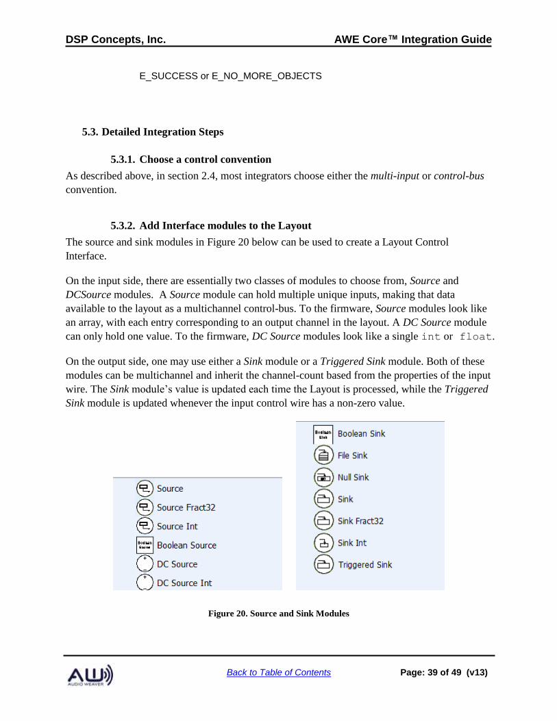
5.3.2. Add Interface modules to the Layout
The source and sink modules in Figure 20 below can be used to create a Layout Control
Interface.
On the input side, there are essentially two classes of modules to choose from, Source and
DCSource modules. A Source module can hold multiple unique inputs, making that data
available to the layout as a multichannel control-bus. To the firmware, Source modules look like
an array, with each entry corresponding to an output channel in the layout. A DC Source module
can only hold one value. To the firmware, DC Source modules look like a single int or float.
On the output side, one may use either a Sink module or a Triggered Sink module. Both of these
modules can be multichannel and inherit the channel-count based from the properties of the input
wire. The Sink module’s value is updated each time the Layout is processed, while the Triggered
Sink module is updated whenever the input control wire has a non-zero value.
Figure 20. Source and Sink Modules
DSP Concepts, Inc. AWE Core™ Integration Guide
Back to Table of Contents Page: 40 of 49 (v13)
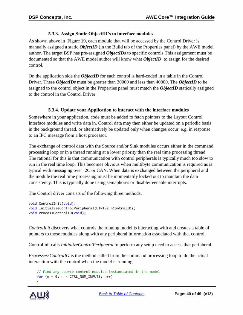
5.3.3. Assign Static ObjectID’s to interface modules
As shown above in Figure 19, each module that will be accessed by the Control Driver is
manually assigned a static ObjectID (in the Build tab of the Properties panel) by the AWE model
author. The target BSP has pre-assigned ObjectIDs to specific controls.This assignment must be
documented so that the AWE model author will know what ObjectID to assign for the desired
control.
On the application side the ObjectID for each control is hard-coded in a table in the Control
Driver. These ObjectIDs must be greater than 30000 and less than 40000. The ObjectID to be
assigned to the control object in the Properties panel must match the ObjectID statically assigned
to the control in the Control Driver.
5.3.4. Update your Application to interact with the interface modules
Somewhere in your application, code must be added to fetch pointers to the Layout Control
Interface modules and write data in. Control data may then either be updated on a periodic basis
in the background thread, or alternatively be updated only when changes occur, e.g. in response
to an IPC message from a host processor.
The exchange of control data with the Source and/or Sink modules occurs either in the command
processing loop or in a thread running at a lower priority than the real time processing thread.
The rational for this is that communication with control peripherals is typically much too slow to
run in the real time loop. This becomes obvious when multibyte communication is required as is
typical with messaging over I2C or CAN. When data is exchanged between the peripheral and
the module the real time processing must be momentatily locked out to maintain the data
consistency. This is typically done using semaphores or disable/reenable interrupts.
The Control driver consists of the following three methods:
void ControlInit(void);
void InitializeControlPeripheral(UINT32 nControlID);
void ProcessControlIO(void);
ControlInit discovers what controls the running model is interacting with and creates a table of
pointers to those modules along with any peripheral information associated with that control.
ControlInit calls InitializeControlPeripheral to perform any setup need to access that peripheral.
ProcessessControlIO is the method called from the command processing loop to do the actual
interaction with the control when the model is running.
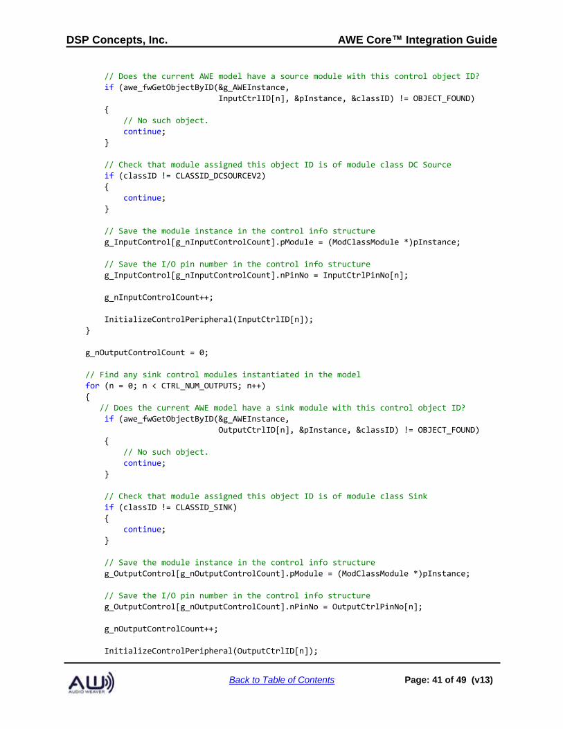
// Find any source control modules instantiated in the model
for (n = 0; n < CTRL_NUM_INPUTS; n++)
{
DSP Concepts, Inc. AWE Core™ Integration Guide
Back to Table of Contents Page: 41 of 49 (v13)
// Does the current AWE model have a source module with this control object ID?
if (awe_fwGetObjectByID(&g_AWEInstance,
InputCtrlID[n], &pInstance, &classID) != OBJECT_FOUND)
{
// No such object.
continue;
}
// Check that module assigned this object ID is of module class DC Source
if (classID != CLASSID_DCSOURCEV2)
{
continue;
}
// Save the module instance in the control info structure
g_InputControl[g_nInputControlCount].pModule = (ModClassModule *)pInstance;
// Save the I/O pin number in the control info structure
g_InputControl[g_nInputControlCount].nPinNo = InputCtrlPinNo[n];
g_nInputControlCount++;
InitializeControlPeripheral(InputCtrlID[n]);
}
g_nOutputControlCount = 0;
// Find any sink control modules instantiated in the model
for (n = 0; n < CTRL_NUM_OUTPUTS; n++)
{
// Does the current AWE model have a sink module with this control object ID?
if (awe_fwGetObjectByID(&g_AWEInstance,
OutputCtrlID[n], &pInstance, &classID) != OBJECT_FOUND)
{
// No such object.
continue;
}
// Check that module assigned this object ID is of module class Sink
if (classID != CLASSID_SINK)
{
continue;
}
// Save the module instance in the control info structure
g_OutputControl[g_nOutputControlCount].pModule = (ModClassModule *)pInstance;
// Save the I/O pin number in the control info structure
g_OutputControl[g_nOutputControlCount].nPinNo = OutputCtrlPinNo[n];
g_nOutputControlCount++;
InitializeControlPeripheral(OutputCtrlID[n]);
DSP Concepts, Inc. AWE Core™ Integration Guide
Back to Table of Contents Page: 42 of 49 (v13)
}
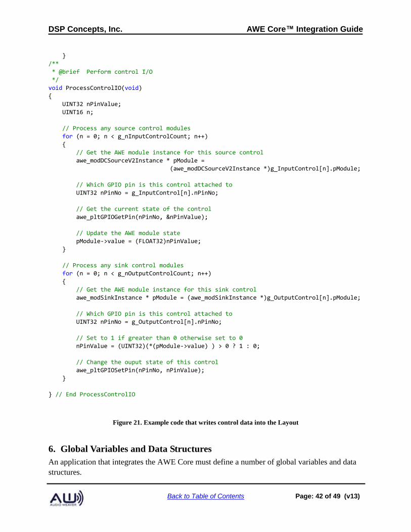
/**
* @brief Perform control I/O
*/
void ProcessControlIO(void)
{
UINT32 nPinValue;
UINT16 n;
// Process any source control modules
for (n = 0; n < g_nInputControlCount; n++)
{
// Get the AWE module instance for this source control
awe_modDCSourceV2Instance * pModule =
(awe_modDCSourceV2Instance *)g_InputControl[n].pModule;
// Which GPIO pin is this control attached to
UINT32 nPinNo = g_InputControl[n].nPinNo;
// Get the current state of the control
awe_pltGPIOGetPin(nPinNo, &nPinValue);
// Update the AWE module state
pModule->value = (FLOAT32)nPinValue;
}
// Process any sink control modules
for (n = 0; n < g_nOutputControlCount; n++)
{
// Get the AWE module instance for this sink control
awe_modSinkInstance * pModule = (awe_modSinkInstance *)g_OutputControl[n].pModule;
// Which GPIO pin is this control attached to
UINT32 nPinNo = g_OutputControl[n].nPinNo;
// Set to 1 if greater than 0 otherwise set to 0
nPinValue = (UINT32)(*(pModule->value) ) > 0 ? 1 : 0;
// Change the ouput state of this control
awe_pltGPIOSetPin(nPinNo, nPinValue);
}
} // End ProcessControlIO
Figure 21. Example code that writes control data into the Layout
6. Global Variables and Data Structures
An application that integrates the AWE Core must define a number of global variables and data
structures.
DSP Concepts, Inc. AWE Core™ Integration Guide
Back to Table of Contents Page: 43 of 49 (v13)
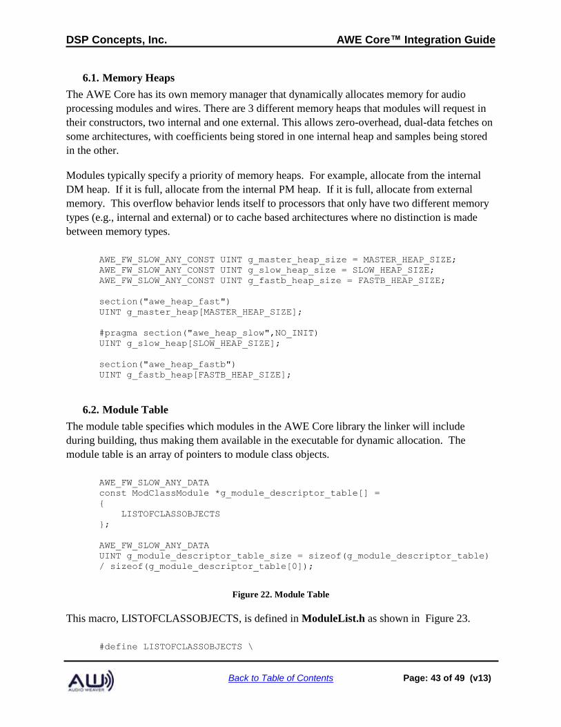
6.1. Memory Heaps
The AWE Core has its own memory manager that dynamically allocates memory for audio
processing modules and wires. There are 3 different memory heaps that modules will request in
their constructors, two internal and one external. This allows zero-overhead, dual-data fetches on
some architectures, with coefficients being stored in one internal heap and samples being stored
in the other.
Modules typically specify a priority of memory heaps. For example, allocate from the internal
DM heap. If it is full, allocate from the internal PM heap. If it is full, allocate from external
memory. This overflow behavior lends itself to processors that only have two different memory
types (e.g., internal and external) or to cache based architectures where no distinction is made
between memory types.
AWE_FW_SLOW_ANY_CONST UINT g_master_heap_size = MASTER_HEAP_SIZE;
AWE_FW_SLOW_ANY_CONST UINT g_slow_heap_size = SLOW_HEAP_SIZE;
AWE_FW_SLOW_ANY_CONST UINT g_fastb_heap_size = FASTB_HEAP_SIZE;
section("awe_heap_fast")
UINT g_master_heap[MASTER_HEAP_SIZE];
#pragma section("awe_heap_slow",NO_INIT)
UINT g_slow_heap[SLOW_HEAP_SIZE];
section("awe_heap_fastb")
UINT g_fastb_heap[FASTB_HEAP_SIZE];
6.2. Module Table
The module table specifies which modules in the AWE Core library the linker will include
during building, thus making them available in the executable for dynamic allocation. The
module table is an array of pointers to module class objects.
AWE_FW_SLOW_ANY_DATA
const ModClassModule *g_module_descriptor_table[] =
{
LISTOFCLASSOBJECTS
};
AWE_FW_SLOW_ANY_DATA
UINT g_module_descriptor_table_size = sizeof(g_module_descriptor_table)
/ sizeof(g_module_descriptor_table[0]);
Figure 22. Module Table
This macro, LISTOFCLASSOBJECTS, is defined in ModuleList.h as shown in Figure 23.
#define LISTOFCLASSOBJECTS \
DSP Concepts, Inc. AWE Core™ Integration Guide
Back to Table of Contents Page: 44 of 49 (v13)
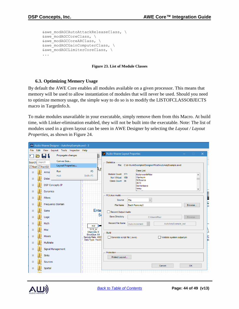
&awe_modAGCAutoAttackReleaseClass, \
&awe_modAGCCoreClass, \
&awe_modAGCCoreARClass, \
&awe_modAGCGainComputerClass, \
&awe_modAGCLimiterCoreClass, \
...
Figure 23. List of Module Classes
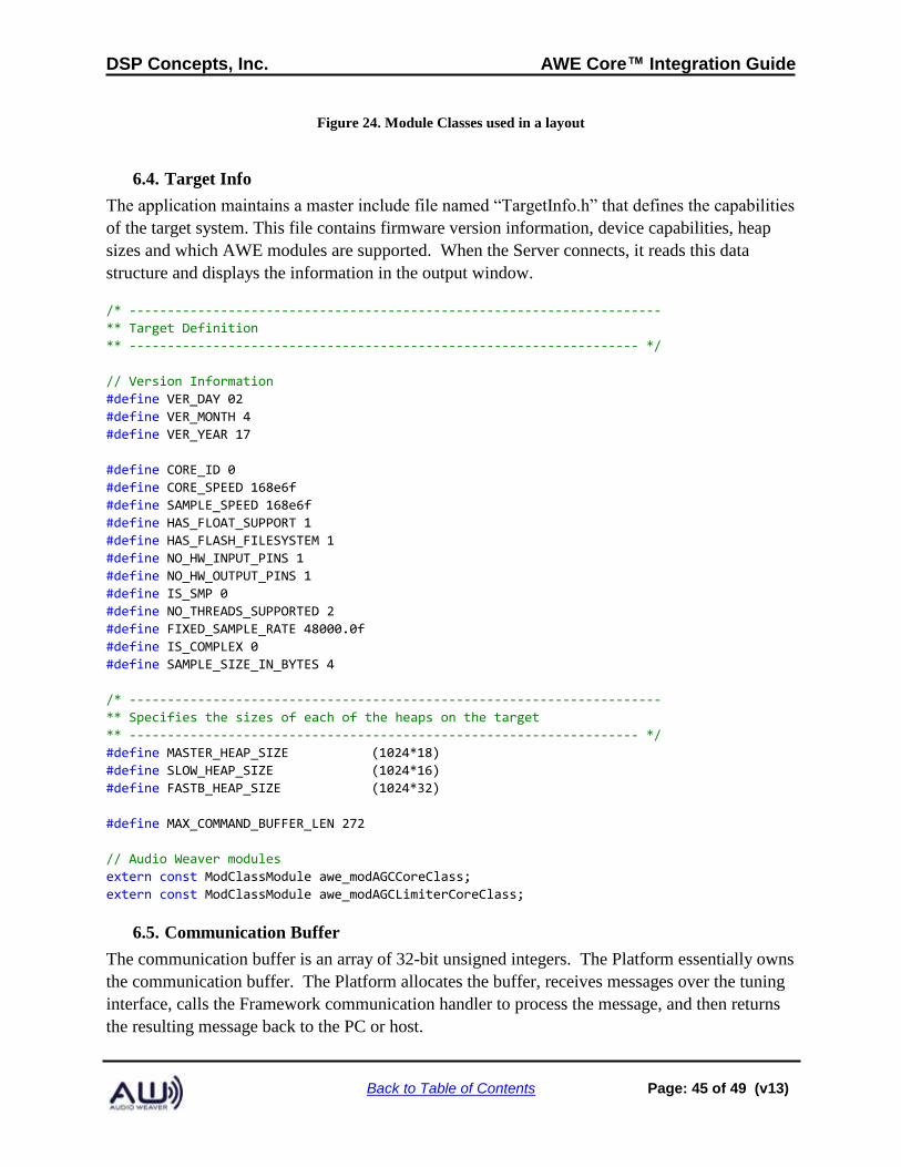
6.3. Optimizing Memory Usage
By default the AWE Core enables all modules available on a given processor. This means that
memory will be used to allow instantiation of modules that will never be used. Should you need
to optimize memory usage, the simple way to do so is to modify the LISTOFCLASSOBJECTS
macro in TargetInfo.h.
To make modules unavailable in your executable, simply remove them from this Macro. At build
time, with Linker-elimination enabled, they will not be built into the executable. Note: The list of
modules used in a given layout can be seen in AWE Designer by selecting the Layout / Layout
Properties, as shown in Figure 24.
DSP Concepts, Inc. AWE Core™ Integration Guide
Back to Table of Contents Page: 45 of 49 (v13)
Figure 24. Module Classes used in a layout
6.4. Target Info
The application maintains a master include file named “TargetInfo.h” that defines the capabilities
of the target system. This file contains firmware version information, device capabilities, heap
sizes and which AWE modules are supported. When the Server connects, it reads this data
structure and displays the information in the output window.
/* ----------------------------------------------------------------------
** Target Definition
** ------------------------------------------------------------------- */
// Version Information
#define VER_DAY 02
#define VER_MONTH 4
#define VER_YEAR 17
#define CORE_ID 0
#define CORE_SPEED 168e6f
#define SAMPLE_SPEED 168e6f
#define HAS_FLOAT_SUPPORT 1
#define HAS_FLASH_FILESYSTEM 1
#define NO_HW_INPUT_PINS 1
#define NO_HW_OUTPUT_PINS 1
#define IS_SMP 0
#define NO_THREADS_SUPPORTED 2
#define FIXED_SAMPLE_RATE 48000.0f
#define IS_COMPLEX 0
#define SAMPLE_SIZE_IN_BYTES 4
/* ----------------------------------------------------------------------
** Specifies the sizes of each of the heaps on the target
** ------------------------------------------------------------------- */
#define MASTER_HEAP_SIZE (1024*18)
#define SLOW_HEAP_SIZE (1024*16)
#define FASTB_HEAP_SIZE (1024*32)
#define MAX_COMMAND_BUFFER_LEN 272
// Audio Weaver modules
extern const ModClassModule awe_modAGCCoreClass;
extern const ModClassModule awe_modAGCLimiterCoreClass;
6.5. Communication Buffer
The communication buffer is an array of 32-bit unsigned integers. The Platform essentially owns
the communication buffer. The Platform allocates the buffer, receives messages over the tuning
interface, calls the Framework communication handler to process the message, and then returns
the resulting message back to the PC or host.
DSP Concepts, Inc. AWE Core™ Integration Guide
Back to Table of Contents Page: 46 of 49 (v13)
AWE_FW_SLOW_ANY_DATA DWORD s_PacketBuffer[MAX_COMMAND_BUFFER_LEN];
6.6. Memory Sections
The Audio Weaver module libraries and Framework code utilize a large number of memory
sections. The memory sections are defined using macros in Framework.h and appear within the
Linker Definition File (LDF). The sections related to code placement:
Macro Section Name Description
AWE_MOD_SLOW_CODE awe_mod_slowcode Non time-critical code used by the audio modules.
AWE_MOD_FAST_CODE awe_mod_fastcode Time-critical code used by the audio modules.
AWE_FW_SLOW_CODE awe_fw_slowcode Non time-critical Framework code.
AWE_FW_FAST_CODE awe_fw_fastcode Time-critical Framework code.
There are 24 memory sections related to data placement. The naming convention used by the
macros is:
AWE_{MOD/FW}_{SLOW/FAST}_{PM/DM/ANY}_{DATA/CONST}
There are 2 x 2 x 3 x 3 = 24 different permutations and each subfield has a specific meaning:
MOD/FW – specifies whether the section applies to modules (MOD) or to the
Framework (FW).
SLOW/FAST – specifies the time criticality of the memory section. SLOW memory is
referenced infrequently or from non-real-time code. It is suitable to be placed in
external memory with little loss of performance. FAST memory is time-critical
and should be placed internally. If internal placement of a FAST section is not
possible, then there will be a performance penalty.
PM/DM/ANY – specifies internal memory placement on the SHARC. PM and DM refer
to two distinct internal memory blocks and enable parallel memory accesses.
Traditionally, these are called "PM" and "DM" spaces on the SHARC. More
recent processors with more than 2 internal memory blocks require placement in
distinct blocks. ANY indicates that placement in PM or DM is unimportant; the
section can go anywhere.
DATA/CONST – DATA sections must be placed in RAM and hold variables that are
being updated. CONST sections store initialized constant data and are suitable for
DSP Concepts, Inc. AWE Core™ Integration Guide
Back to Table of Contents Page: 47 of 49 (v13)
inclusion into ROM.
The corresponding section names (which must appear within the LDF) are lower case. For
example, AWE_MOD_SLOW_DM_DATA is placed in the section awe_mod_slowdmdata.
7. Framework Prerequisites
We are often asked about integrating the Audio Weaver Core into an existing real-time
framework. This section lists the features and capabilities required of a framework to support
Audio Weaver. You can think of this information as a summary of the requirements and APIs
previously listed.
7.1. Basic Processor and Board Initialization
1. Processor can boot from NVRAM
2. PLL and all clocking subsystems initialized
3. Memory and Cache's configuredAudio Subsystem working
4. Audio drivers implemented (TMD/I2s serial ports configured with proper clock polarities,
etc)
5. DMA channels configured, with ping-pong buffers for DMA RX and TX
6. If there are multiple audio peripherals, all serial ports and DMA should be started
synchronously
7. Audio devices (CODECs, ADCs, DACs, network interfaces) configured and verified to
be passing clean audio
8. Proper sample rates, clock polarities, etc
9. CODEC gains, filters, and mixers have to be properly configured
10. Communications subsystem working
11. Communication drivers (SPI, USB, RS232, TCP/IP, etc) configured and verified to be
exchanging clean communications data with Windows PC.
12. Proper baud rates, clock polarities, etc
7.2. Simple “Audio Passthru” Application
To ensure we're integrating the AWE Core into a known-good environment, it's required that a
DSP Concepts, Inc. AWE Core™ Integration Guide
Back to Table of Contents Page: 48 of 49 (v13)
simple "Audio Passthru" application be functional. This "hello world" application should simply
pass audio from input to output, demonstrating that the PCB, audio peripherals, components, and
baseline configuration are all functional and stable.
1. CODEC (etc) configured properly
2. I2S/TDM serial port I/O is serviced by double buffered ("ping-pong"), block based DMA.
(The DMA needs to run in the background without needing processor intervention.)
3. The DMA must generate an interrupt at the end of each block transfer. (Polling for the
completion of a block transfer in the background/main loop won't work. The main loop is
reserved for non-real-time critical operations.)
4. In the DMA Interrupt handler, ping-pong buffers are toggled, and audio is simply copied
from RX to TX buffer
At this point, the audio I/O APIs described in Section 4 can be called from the DMA interrupt
handler.
7.3. Simple “Echo-Back” Application
Tuning commands (and replies) are exchanged in realtime between Audio Weaver Designer on
the PC and the AWE Core library on the embedded target. This communication can happen over
a number of different protocols, listed below in order of throughput (higher bandwidth interfaces
provide a better user experience).
1. Ethernet - standard TCPI/P interface.
2. USB - HID device
3. SPI - custom 32-bit protocol
4. UART - custom byte-based protocol
Similar to the requirements for the Audio subsystem, the example application should also include
'Echo-back' functionality on the chosen communications device. Here, each byte/word/packet
received should be immediately transmitted back to the PC, demonstrating that the PCB, comms
peripherals and components and baseline-configuration are all functional and stable.
• Comm peripheral is enabled and interrupts are triggered on a byte/word/packet boundary
(depending on protocol)
• In the Comm Interrupt handler, RX data should be copied to the TX buffer to be sent
back to PC.
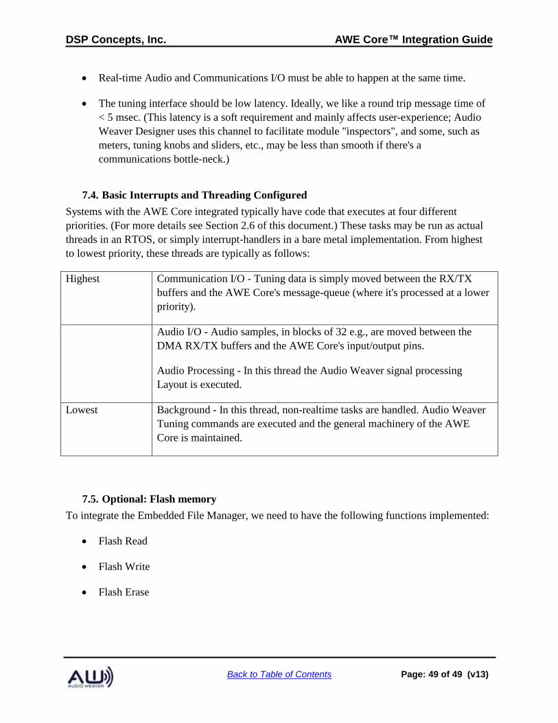
DSP Concepts, Inc. AWE Core™ Integration Guide
Back to Table of Contents Page: 49 of 49 (v13)
• Real-time Audio and Communications I/O must be able to happen at the same time.
• The tuning interface should be low latency. Ideally, we like a round trip message time of
< 5 msec. (This latency is a soft requirement and mainly affects user-experience; Audio
Weaver Designer uses this channel to facilitate module "inspectors", and some, such as
meters, tuning knobs and sliders, etc., may be less than smooth if there's a
communications bottle-neck.)
7.4. Basic Interrupts and Threading Configured
Systems with the AWE Core integrated typically have code that executes at four different
priorities. (For more details see Section 2.6 of this document.) These tasks may be run as actual
threads in an RTOS, or simply interrupt-handlers in a bare metal implementation. From highest
to lowest priority, these threads are typically as follows:
Highest Communication I/O - Tuning data is simply moved between the RX/TX
buffers and the AWE Core's message-queue (where it's processed at a lower
priority).
Audio I/O - Audio samples, in blocks of 32 e.g., are moved between the
DMA RX/TX buffers and the AWE Core's input/output pins.
Audio Processing - In this thread the Audio Weaver signal processing
Layout is executed.
Lowest Background - In this thread, non-realtime tasks are handled. Audio Weaver
Tuning commands are executed and the general machinery of the AWE
Core is maintained.
7.5. Optional: Flash memory
To integrate the Embedded File Manager, we need to have the following functions implemented:
• Flash Read
• Flash Write
• Flash Erase