Embed Size (px)
Citation preview

3-1
Chapter 3
Award BIOS
This chapter tells you how to configure the system parameters. You mayupdate your BIOS via AWARD Flash Utility.
Important: Because the BIOS code is the mostoften changed part of the mainboard design, theBIOS information contained in this chapter(especially the Chipset Setup parameters) may bea little different compared to the actual BIOS thatcame with your mainboard. These changes areimplemented to further enhance systemperformance.
AWARD BIOS
3-2
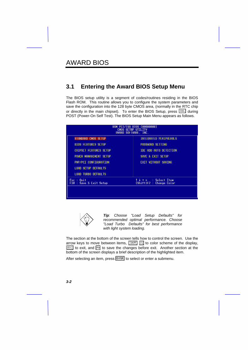
3.1 Entering the Award BIOS Setup Menu
The BIOS setup utility is a segment of codes/routines residing in the BIOSFlash ROM. This routine allows you to configure the system parameters andsave the configuration into the 128 byte CMOS area, (normally in the RTC chipor directly in the main chipset). To enter the BIOS Setup, press duringPOST (Power-On Self Test). The BIOS Setup Main Menu appears as follows.
Tip: Choose "Load Setup Defaults" forrecommended optimal performance. Choose"Load Turbo Defaults" for best performancewith light system loading.
The section at the bottom of the screen tells how to control the screen. Use thearrow keys to move between items, to color scheme of the display,
to exit, and to save the changes before exit. Another section at thebottom of the screen displays a brief description of the highlighted item.
After selecting an item, press to select or enter a submenu.

AWARD BIOS
3-3
3.2 Standard CMOS Setup
The "Standard CMOS Setup" sets the basic system parameters such as thedate, time, and the hard disk type. Use the arrow keys to highlight an item and
or to select the value for each item.
Standard CMOS à DateTo set the date, highlight the Date parameter. Press or to set thecurrent date. The date format is month, date, and year.
Standard CMOS à TimeTo set the time, highlight the Time parameter. Press or to set thecurrent time in hour, minute, and second format. The time is based on the 24hour military clock.
AWARD BIOS
3-4
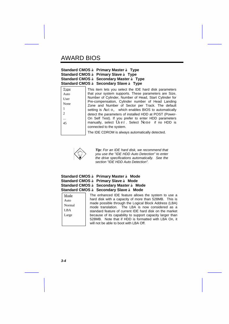
Standard CMOS à Primary Master à TypeStandard CMOS à Primary Slave à TypeStandard CMOS à Secondary Master à TypeStandard CMOS à Secondary Slave à Type
TypeAutoUserNone12...45
This item lets you select the IDE hard disk parametersthat your system supports. These parameters are Size,Number of Cylinder, Number of Head, Start Cylinder forPre-compensation, Cylinder number of Head LandingZone and Number of Sector per Track. The defaultsetting is Auto, which enables BIOS to automaticallydetect the parameters of installed HDD at POST (Power-On Self Test). If you prefer to enter HDD parametersmanually, select User. Select None if no HDD isconnected to the system.
The IDE CDROM is always automatically detected.
Tip: For an IDE hard disk, we recommend thatyou use the "IDE HDD Auto Detection" to enterthe drive specifications automatically. See thesection "IDE HDD Auto Detection".
Standard CMOS à Primary Master à ModeStandard CMOS à Primary Slave à ModeStandard CMOS à Secondary Master à ModeStandard CMOS à Secondary Slave à Mode
ModeAutoNormalLBALarge
The enhanced IDE feature allows the system to use ahard disk with a capacity of more than 528MB. This ismade possible through the Logical Block Address (LBA)mode translation. The LBA is now considered as astandard feature of current IDE hard disk on the marketbecause of its capability to support capacity larger than528MB. Note that if HDD is formatted with LBA On, itwill not be able to boot with LBA Off.

AWARD BIOS
3-5
Standard CMOS à Drive AStandard CMOS à Drive B
Drive ANone360KB 5.25"1.2MB 5.25"720KB 3.5"1.44MB 3.5"2.88MB 3.5"
These items select floppy drive type. The available settingsand types supported by the mainboard are listed on the left.
Standard CMOS à VideoVideoEGA/VGACGA40CGA80Mono
This item specifies the type of video card in use. Thedefault setting is VGA/EGA. Since current PCs use VGAonly, this function is almost useless and may bedisregarded in the future.
Standard CMOS à Halt OnHalt OnNo ErrorsAll ErrorsAll, But KeyboardAll, But DisketteAll, But Disk/Key
This parameter enables you to control the system stops incase of Power-On Self Test (POST) error.

AWARD BIOS
3-6
3.3 BIOS Features Setup
This screen appears when you select the option "BIOS Features Setup" fromthe main menu.
BIOS Features à Virus WarningVirusWarning
EnabledDisabled
Set this parameter to Enabled to activate the warningmessage. This feature protects the boot sector and partitiontable of your hard disk from virus intrusion.
Any attempt during boot up to write to the boot sector of thehard disk drive stops the system and the following warningmessage appears on the screen. Run an anti-virus program tolocate the problem.
! WARNING !Disk Boot Sector is to be modified
Type "Y" to accept write, or "N" to abort writeAward Software, Inc.

AWARD BIOS
3-7
BIOS Features à External Cache
External Cache
EnabledDisabled
Enabling this parameter activates the secondary cache(currently, PBSRAM cache). Disabling the parameterslows down the system. Therefore, we recommend thatyou leave it enabled unless you are troubleshooting aproblem.
BIOS Features à Power-On Self-TestQuick Power-onSelf-testEnableDisabled
This parameter speeds up POST by skipping someitems that are normally checked.
BIOS Features à Boot SequenceBoot SequenceA,C,SCSIC,A,SCSIC,CDROM,ACDROM,C,AD,A,SCSIE,A,SCSIF,A,SCSISCSI,A,CSCSI,C,AC onlyLS/ZIP,C
This parameter allows you to specify the system bootup search sequence. The hard disk ID are listed below:
C: Primary master
D: Primary slave
E: Secondary master
F: Secondary slave
LS: LS120
Zip: IOMEGA ZIP Drive
BIOS Features à Swap Floppy DriveSwap Floppy DriveEnabledDisabled
This item allows you to swap floppy drives. Forexample, if you have two floppy drives (A and B), youcan assign the first drive as drive B and the seconddrive as drive A or vice-versa.

AWARD BIOS
3-8
BIOS Features à Boot Up Floppy SeekBoot Up FloppySeekEnabledDisabled
When enabled, the BIOS issues the seek command tothe floppy drive during POST to move floppy drive headforward and backward.
BIOS Features à Boot Up NumLock StatusBoot UpNumLock StatusOnOff
Setting this parameter to On enables the numericfunction of the numeric keypad. Set this parameter toOff to disregard the function. Disabling the numericfunction allows you to use the numeric keypad for cursorcontrol.
BIOS Features à Boot Up System SpeedBoot Up SystemSpeedHighLow
Select High or Low system speed after boot.
BIOS Features à Gate A20 OptionGate A20 OptionNormalFast
This item is used to select Gate A20 Option.
BIOS Features à Memory Parity CheckMemory ParityCheckDisabledEnabled
This item is used to enable or disable DRAM paritycheck function.
BIOS Features à Typematic Rate SettingTypematic RateSettingEnabledDisabled
Set this parameter to Enable/Disable the keyboardrepeat function. When enabled, continually holding downa key on the keyboard will generate repeatedlykeystrokes.

AWARD BIOS
3-9
BIOS Features à Typematic Rate (Chars/Sec)Typematic Rate68101215202430
This item allows you to control the speed of repeatedkeystrokes. The default is 30 characters/sec.
BIOS Features à Typematic Delay (Msec)Typematic Delay2505007501000
This parameter allows you to control the delay timebetween the first and the second keystroke (where therepeated keystrokes begin). The typematic delaysettings are 250, 500, 750, and 1000 msec.
BIOS Features à Security OptionSecurity OptionSetupSystem
The System option limits access to both the Systemboot and BIOS setup. A prompt asking you to enteryour password appears on the screen every time youboot the system.
The Setup option limits access only to BIOS setup.
To disable the security option, select Password Settingfrom the main menu, don't type anything and just press<Enter>.
BIOS Features à PCI/VGA Palette SnoopPCI/VGA PaletteSnoopEnabledDisabled
Enabling this item informs the PCI VGA card to keepsilent (and to prevent conflict) when palette register isupdated (i.e., accepts data without responding anycommunication signals). This is useful only when twodisplay cards use the same palette address andplugged in the PCI bus at the same time (such asMPEQ or Video capture). In such case, PCI VGA issilent while MPEQ/Video capture is set to functionnormally.
AWARD BIOS
3-10
BIOS Features à OS Select for DRAM > 64MBOS Select forDRAM > 64MBOS/2Non-OS/2
Set to OS/2 if your system is utilizing an OS/2 operatingsystem and has a memory size of more than 64 MB.
BIOS Features à Video BIOS ShadowVideo BIOSShadowEnabledDisabled
VGA BIOS Shadowing means to copy video display cardBIOS into the DRAM area. This enhances systemperformance because DRAM access time is faster thanROM.
BIOS Features à C800-CBFF ShadowBIOS Features à CC00-CFFF ShadowBIOS Features à D000-D3FF ShadowBIOS Features à D400-D7FF ShadowBIOS Features à D800-DBFF ShadowBIOS Features à DC00-DFFF Shadow
C8000-CBFFFShadowEnabledDisabled
These six items are for shadowing ROM code on otherexpansion cards. Before you set these parameters, youneed to know the specific addresses of that ROM code.If you do not know this information, enable all the ROMshadow settings. Note that the F000 and E000segments are always shadowed because BIOS codeoccupies these areas.
AWARD BIOS
3-11
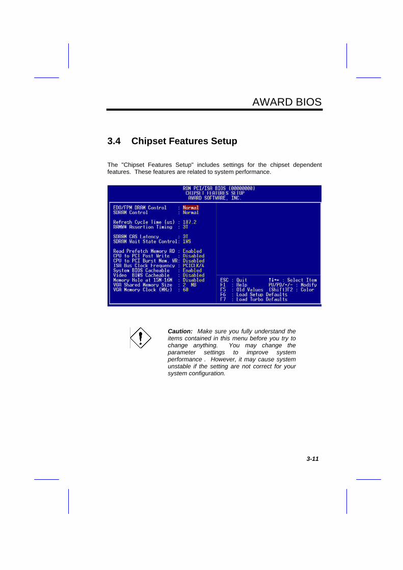
3.4 Chipset Features Setup
The "Chipset Features Setup" includes settings for the chipset dependentfeatures. These features are related to system performance.
Caution: Make sure you fully understand theitems contained in this menu before you try tochange anything. You may change theparameter settings to improve systemperformance . However, it may cause systemunstable if the setting are not correct for yoursystem configuration.

AWARD BIOS
3-12
Chipset Features à EDO/FPM DRAM ControlEDO/FPM TimingControlFastNormal
This item is used to control EDO/FPM timing. If youfind system unstable, please try to set this item toNormal.
Chipset Features à SDRAM ControlSDRAM TimingControlFastNormal
This item is used to control SDRAM timing. If youfind system unstable, please try to set this item toNormal.
Chipset Features à Refresh Cycle Time (us)Refresh Cycle Time(us)15.662.4124.8187.2
This option lets you set the cycle time for the chipsetto refresh DRAM to avoid losing data. The unit ismicro second (us).
Chipset Features à RAMW# Assertion TimingRAMW# AssertionTiming2T3T
This parameter specifies the number of clocksrequired to assert the DRAM write control signalwhen read cycle followed by write cycle.
Chipset Features à SDRAM CAS LatencySDRAM CASLatency2T3T
This parameter specifies the number of clocks ofSDRAM CAS Latency. This is very importantparameter affects SDRAM performance. If yourSDRAM has unstable problem, set to 3T.

AWARD BIOS
3-13
Chipset Features à SDRAM Wait State ControlSDRAM Wait StateControl0WS1WS
This parameter specifies the number of clocks ofSDRAM Wait State Control during Precharge.
0WS: zero wait state.1WS: one wait state.
Chipset Features à Read Prefetch Memory RDRead PrefetchMemory RDEnabledDisabled
This item lets you control the Read Prefetch of thememory read of PCI bus command. When enabled,Memory Read Multiple and Memory Read Line of PCIcommands always do prefetch.
Chipset Features à CPU to PCI Post WriteCPU to PCI PostWrite3T4TDisabled
This parameter specifies the number of clocks forCPU to PCI Post Write cycle.
Chipset Features à CPU to PCI Burst Mem. WRCPU to PCI BurstMem. WREnabledDisabled
This item lets you control the CPU to PCI BurstMemory Write.
Chipset Features à ISA Bus Clock FrequencyISA Bus ClockFrequencyPCICLK/3PCICLK/47.159MHz
This item lets you select the ISA bus clock. Normally,the PCI bus clock is the CPU bus (external) clockdivided by 2, PCICLK=CPUCLK/2. For example,CPUCLK=66MHz, PCICLK=66/2=33MHz, ISA busCLK=33/4=8.25MHz.
AWARD BIOS
3-14
Chipset Features à System BIOS CacheableSystem BIOSCacheableEnabledDisabled
Enabling this item allows you to cache the systemBIOS to further enhance system performance.
Chipset Features à Video BIOS CacheableVideo BIOSCacheableEnabledDisabled
Allows the video BIOS to be cached to allow fastervideo performance.
Chipset Features à Memory Hole At 15M-16MMemory Hole At15M-16MEnabledDisabled
This option lets you reserve system memory area forspecial ISA cards. The chipset accesses code/data ofthese areas from the ISA bus directly. Normally, theseareas are reserved for memory mapped I/O card.
Chipset Features à VGA Shared Memory SizeVGA SharedMemory Size0.5MB1MB1.5MB2MB2.5MB3MB3.5MB4MB
The onboard VGA need to share a memory size withthe system memory. You may set a larger size forgetting better performance. The shared memory sizeis up to 4MB.
Chipset Features à VGA Memory Clock (MHz)VGA Memory Clock556066
This item is used to set the VGA memory clock.You can get the best performance by setting thisitem to 66.
AWARD BIOS
3-15
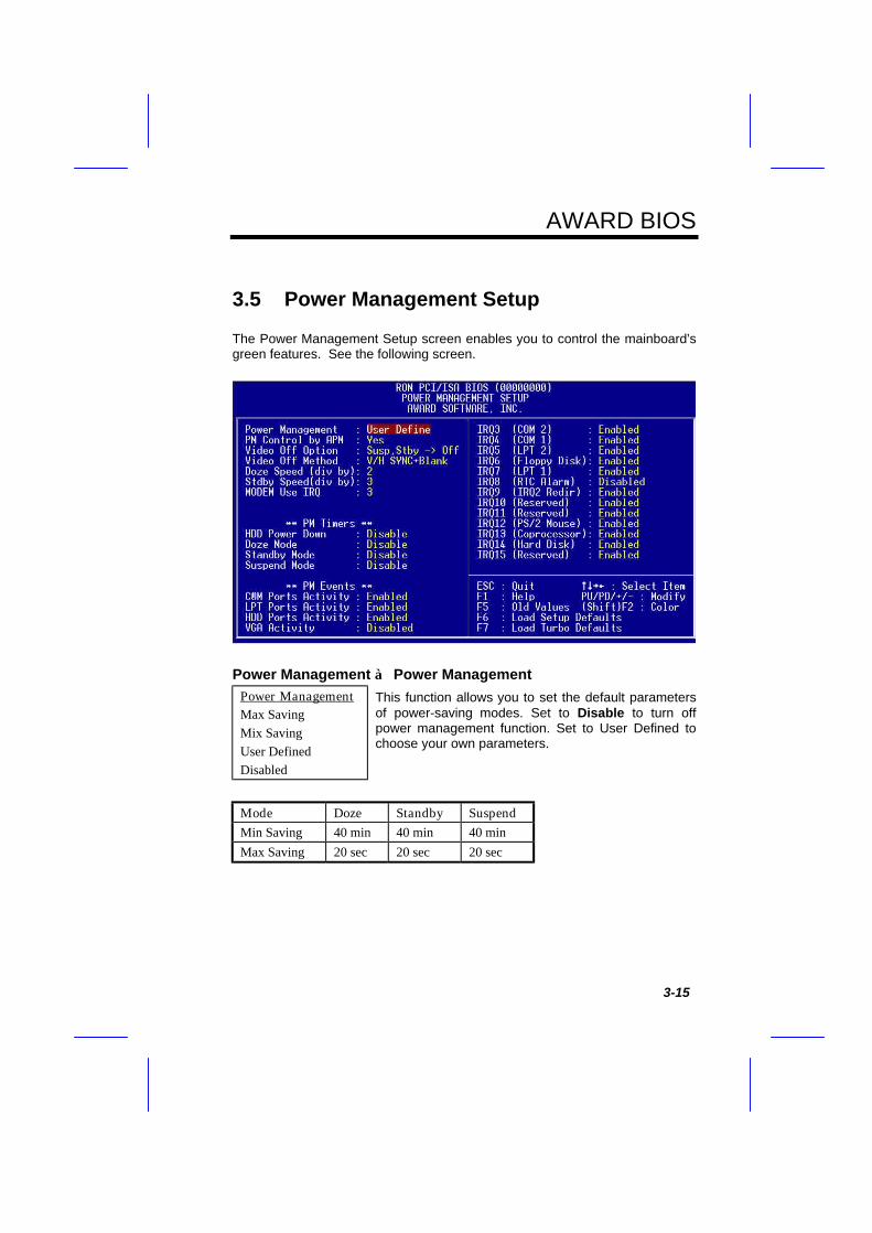
3.5 Power Management Setup
The Power Management Setup screen enables you to control the mainboard’sgreen features. See the following screen.
Power Management à Power ManagementPower ManagementMax SavingMix SavingUser DefinedDisabled
This function allows you to set the default parametersof power-saving modes. Set to Disable to turn offpower management function. Set to User Defined tochoose your own parameters.
Mode Doze Standby SuspendMin Saving 40 min 40 min 40 minMax Saving 20 sec 20 sec 20 sec
AWARD BIOS
3-16
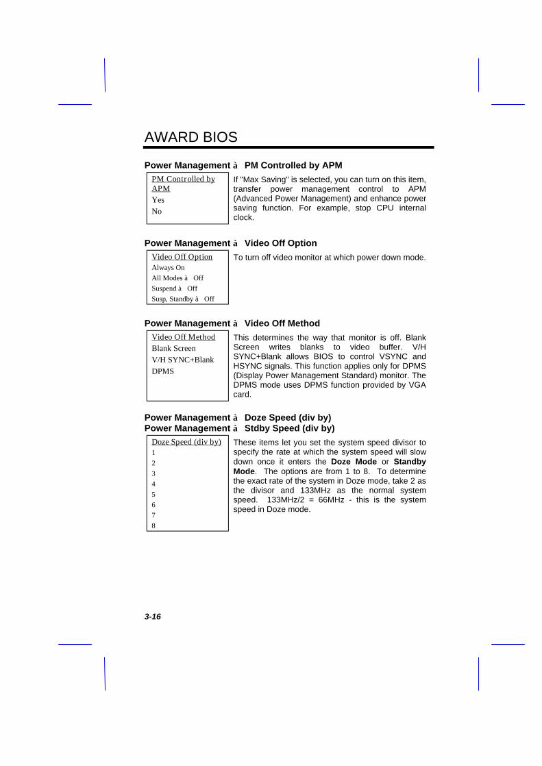
Power Management à PM Controlled by APMPM Controlled byAPMYesNo
If "Max Saving" is selected, you can turn on this item,transfer power management control to APM(Advanced Power Management) and enhance powersaving function. For example, stop CPU internalclock.
Power Management à Video Off OptionVideo Off OptionAlways OnAll Modes à OffSuspend à OffSusp, Standby à Off
To turn off video monitor at which power down mode.
Power Management à Video Off MethodVideo Off MethodBlank ScreenV/H SYNC+BlankDPMS
This determines the way that monitor is off. BlankScreen writes blanks to video buffer. V/HSYNC+Blank allows BIOS to control VSYNC andHSYNC signals. This function applies only for DPMS(Display Power Management Standard) monitor. TheDPMS mode uses DPMS function provided by VGAcard.
Power Management à Doze Speed (div by)Power Management à Stdby Speed (div by)
Doze Speed (div by)12345678
These items let you set the system speed divisor tospecify the rate at which the system speed will slowdown once it enters the Doze Mode or StandbyMode. The options are from 1 to 8. To determinethe exact rate of the system in Doze mode, take 2 asthe divisor and 133MHz as the normal systemspeed. 133MHz/2 = 66MHz - this is the systemspeed in Doze mode.

AWARD BIOS
3-17
Power Management à Modem Use IRQModem Use IRQNA3456791011
This item tells BIOS/Chipset the IRQ of your modem.This allows BIOS/Chipset to monitor the activities ofthe modem connected to your system.
Power Management à HDD Power DownHDD Power DownDisabled1 Min.....15 Min
This option lets you specify the IDE HDD idle timebefore the device enters the power down state. Thisitem is independent from the power states described inthis section (Standby and Suspend).
Power Management à Doze ModeDoze ModeDisabled20 Sec1 Min5 Min10 Min15 Min20 Min30 Min40 Min
This item lets you set the period of time after whichthe system enters into Doze mode. In this mode, theCPU clock slows down. The ratio is specified in the"Throttle Duty Cycle". Any activity detected returns thesystem to full power. The system activity (or event) isdetected by monitoring the IRQ signals.

AWARD BIOS
3-18
Power Management à Standby ModeStandby ModeDisabled20 Sec1 Min5 Min10 Min15 Min20 Min30 Min40 Min
This item lets you set the period of time after which thesystem enters into Standby mode. In this mode, CPUclock slows down, hard disk will be shut off and themonitor power-saving feature activates. Any activitydetected returns the system to full power. The systemactivity (or event) is detected by monitoring the IRQsignals.
Power Management à Suspend ModeSuspend ModeDisabled20 Sec1 Min5 Min10 Min15 Min20 Min30 Min40 Min
This item lets you set the period of time after which thesystem enters into Suspend mode. In this mode, CPUclock stops, all other devices will be shut off. Anyactivity detected returns the system to full power. Thesystem activity(or event) is detected by monitoring theIRQ signals.
Power Management à COM Ports ActivityPower Management à LPT Ports ActivityPower Management à HDD Ports ActivityPower Management à VGA Activity
COM Ports ActivityEnabledDisabled
To enable or disable the detection of COM port, LPT,HDD, VGA activities for power down state transition.

AWARD BIOS
3-19
Power Management à IRQ3 (COM2)Power Management à IRQ4 (COM1)Power Management à IRQ5 (LPT2)Power Management à IRQ6 (Floppy Disk)Power Management à IRQ8 (RTC Alarm)Power Management à IRQ9 (IRQ2 Redir)Power Management à IRQ10 (Reserved)Power Management à IRQ11 (Reserved)Power Management à IRQ12 (PS/2 Mouse)Power Management à IRQ13 (Coprocessor)Power Management à IRQ14 (Hard Disk)Power Management à IRQ15 (Reserved)
IRQ2 (COM2)EnabledDisabled
To enable or disable the detection of IRQ event forpower down state transition. Note that OS2 hasperiodically IRQ8 (RTC) interruptions, If IRQ8 is notset to Disabled, OS/2 may fail to go intoDoze/Standby/Suspend mode.

AWARD BIOS
3-20
3.6 PNP/PCI Configuration Setup
The PNP/PCI Configuration Setup allows you to configure the ISA and PCIdevices installed in your system. The following screen appears if you select theoption "PNP/PCI Configuration Setup" from the main menu.
PNP/PCI Configuration à PnP OS InstalledPnP OS InstalledYesNo
Normally, the PnP resources are allocated by BIOSduring POST (Power-On Self Test). If you are usinga PnP operating system (such as Windows 95), setthis item to Yes to inform BIOS to configure only theresources needed for booting (VGA/IDE or SCSI).The rest of system resources will be allocated byPnP operating system.
AWARD BIOS
3-21
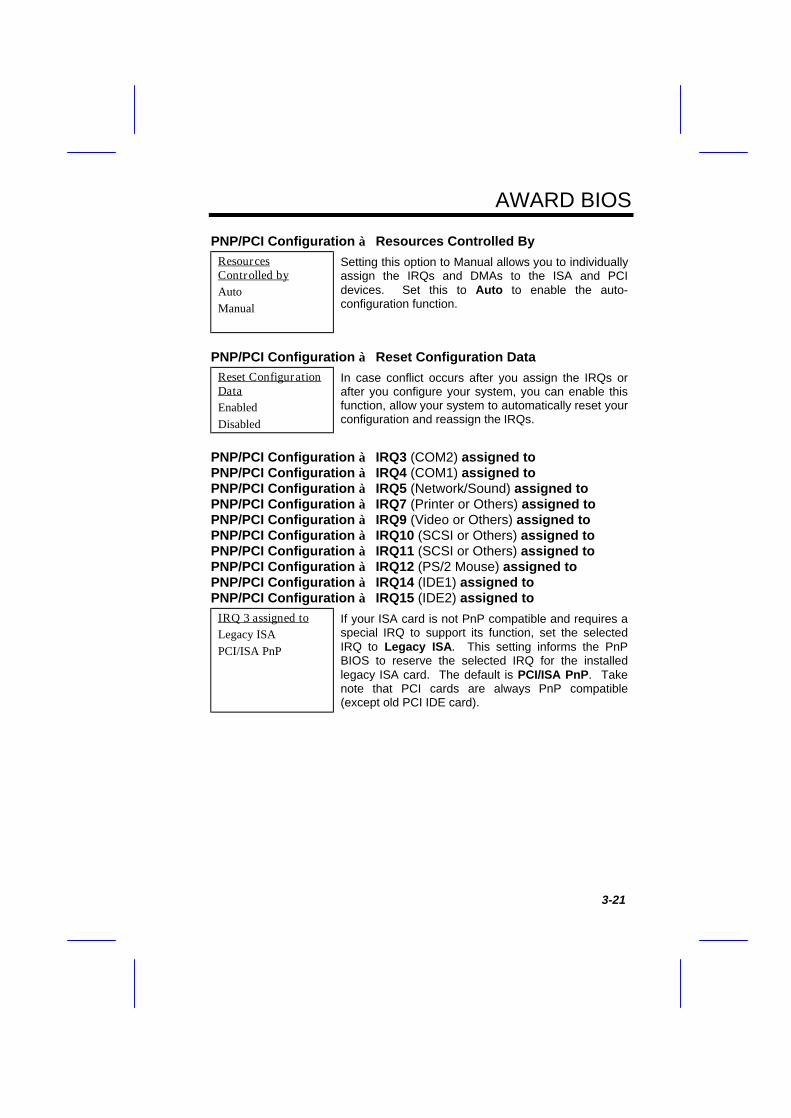
PNP/PCI Configuration à Resources Controlled ByResourcesControlled byAutoManual
Setting this option to Manual allows you to individuallyassign the IRQs and DMAs to the ISA and PCIdevices. Set this to Auto to enable the auto-configuration function.
PNP/PCI Configuration à Reset Configuration DataReset ConfigurationDataEnabledDisabled
In case conflict occurs after you assign the IRQs orafter you configure your system, you can enable thisfunction, allow your system to automatically reset yourconfiguration and reassign the IRQs.
PNP/PCI Configuration à IRQ3 (COM2) assigned toPNP/PCI Configuration à IRQ4 (COM1) assigned toPNP/PCI Configuration à IRQ5 (Network/Sound) assigned toPNP/PCI Configuration à IRQ7 (Printer or Others) assigned toPNP/PCI Configuration à IRQ9 (Video or Others) assigned toPNP/PCI Configuration à IRQ10 (SCSI or Others) assigned toPNP/PCI Configuration à IRQ11 (SCSI or Others) assigned toPNP/PCI Configuration à IRQ12 (PS/2 Mouse) assigned toPNP/PCI Configuration à IRQ14 (IDE1) assigned toPNP/PCI Configuration à IRQ15 (IDE2) assigned to
IRQ 3 assigned toLegacy ISAPCI/ISA PnP
If your ISA card is not PnP compatible and requires aspecial IRQ to support its function, set the selectedIRQ to Legacy ISA. This setting informs the PnPBIOS to reserve the selected IRQ for the installedlegacy ISA card. The default is PCI/ISA PnP. Takenote that PCI cards are always PnP compatible(except old PCI IDE card).
AWARD BIOS
3-22
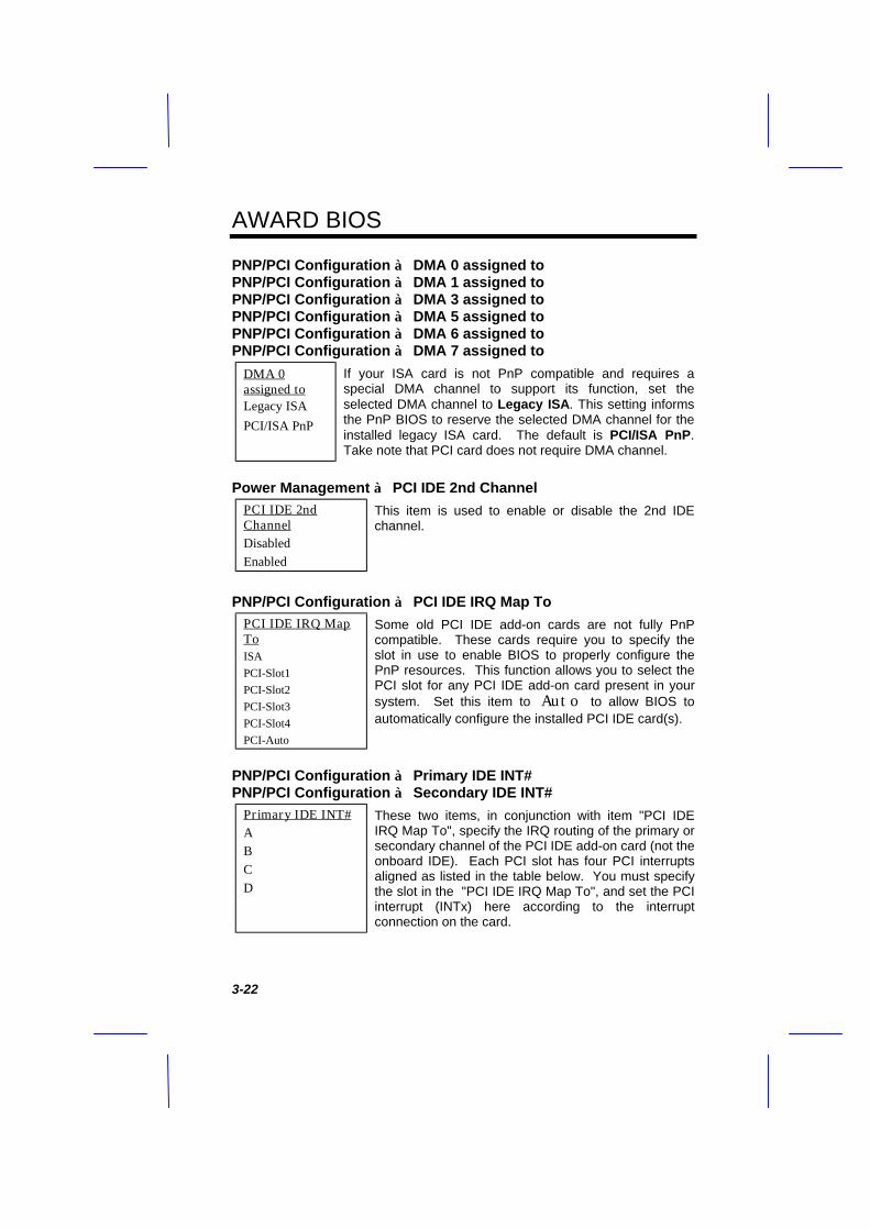
PNP/PCI Configuration à DMA 0 assigned toPNP/PCI Configuration à DMA 1 assigned toPNP/PCI Configuration à DMA 3 assigned toPNP/PCI Configuration à DMA 5 assigned toPNP/PCI Configuration à DMA 6 assigned toPNP/PCI Configuration à DMA 7 assigned to
DMA 0assigned toLegacy ISA
PCI/ISA PnP
If your ISA card is not PnP compatible and requires aspecial DMA channel to support its function, set theselected DMA channel to Legacy ISA. This setting informsthe PnP BIOS to reserve the selected DMA channel for theinstalled legacy ISA card. The default is PCI/ISA PnP.Take note that PCI card does not require DMA channel.
Power Management à PCI IDE 2nd ChannelPCI IDE 2ndChannelDisabledEnabled
This item is used to enable or disable the 2nd IDEchannel.
PNP/PCI Configuration à PCI IDE IRQ Map ToPCI IDE IRQ MapToISAPCI-Slot1PCI-Slot2PCI-Slot3PCI-Slot4PCI-Auto
Some old PCI IDE add-on cards are not fully PnPcompatible. These cards require you to specify theslot in use to enable BIOS to properly configure thePnP resources. This function allows you to select thePCI slot for any PCI IDE add-on card present in yoursystem. Set this item to Auto to allow BIOS toautomatically configure the installed PCI IDE card(s).
PNP/PCI Configuration à Primary IDE INT#PNP/PCI Configuration à Secondary IDE INT#
Primary IDE INT#ABCD
These two items, in conjunction with item "PCI IDEIRQ Map To", specify the IRQ routing of the primary orsecondary channel of the PCI IDE add-on card (not theonboard IDE). Each PCI slot has four PCI interruptsaligned as listed in the table below. You must specifythe slot in the "PCI IDE IRQ Map To", and set the PCIinterrupt (INTx) here according to the interruptconnection on the card.
AWARD BIOS
3-23
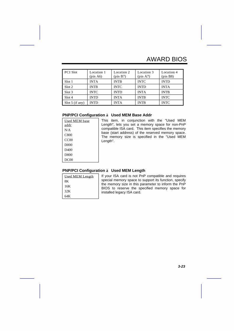
PCI Slot Location 1(pin A6)
Location 2(pin B7)
Location 3(pin A7)
Location 4(pin B8)
Slot 1 INTA INTB INTC INTDSlot 2 INTB INTC INTD INTASlot 3 INTC INTD INTA INTBSlot 4 INTD INTA INTB INTCSlot 5 (if any) INTD INTA INTB INTC
PNP/PCI Configuration à Used MEM Base AddrUsed MEM baseaddrN/AC800CC00D000D400D800DC00
This item, in conjunction with the "Used MEMLength", lets you set a memory space for non-PnPcompatible ISA card. This item specifies the memorybase (start address) of the reserved memory space.The memory size is specified in the "Used MEMLength".
PNP/PCI Configuration à Used MEM LengthUsed MEM Length8K16K32K64K
If your ISA card is not PnP compatible and requiresspecial memory space to support its function, specifythe memory size in this parameter to inform the PnPBIOS to reserve the specified memory space forinstalled legacy ISA card.

AWARD BIOS
3-24
3.7 Load Setup Defaults
The "Load Setup Defaults" option loads optimized settings for optimum systemperformance. Optimal settings are relatively safer than the Turbo settings. Werecommend you to use the Optimal settings if your system has large memorysize and fully loaded with add-on card (for example, a file server using double-sided 8MB SIMM x4 and SCSI plus Network card occupying the PCI and ISAslots).
Optimal is not the slowest setting for this mainboard. If you need to verify aunstable problem, you may manually set the parameter in the "BIOS FeaturesSetup" and "Chipset Features Setup" to get slowest and safer setting.
3.8 Load Turbo Defaults
The "Load Turbo Defaults" option gives better performance than Optimalvalues. However, Turbo values may not be the best setting of this mainboardbut these values are qualified by the AOpen RD and QA department as thereliable settings especially if you have limited loading of add-on card andmemory size (for example, a system that contains only a VGA/Sound card andtwo SIMMs).
To attain the best system performance, you may manually set the parametersin the "Chipset Features Setup" to get proprietary setting. Make sure that youknow and understand the functions of every item in Chipset Setup menu. Theperformance difference of Turbo from Optimal is normally around 3% to 10%,depending on the chipset and the application.
AWARD BIOS
3-25
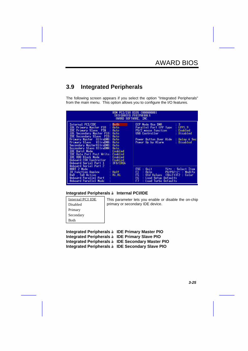
3.9 Integrated Peripherals
The following screen appears if you select the option "Integrated Peripherals"from the main menu. This option allows you to configure the I/O features.
Integrated Peripherals à Internal PCI/IDEInternal PCI IDEDisabledPrimarySecondaryBoth
This parameter lets you enable or disable the on-chipprimary or secondary IDE device.
Integrated Peripherals à IDE Primary Master PIOIntegrated Peripherals à IDE Primary Slave PIOIntegrated Peripherals à IDE Secondary Master PIOIntegrated Peripherals à IDE Secondary Slave PIO

AWARD BIOS
3-26
IDE PrimaryMaster PIOAutoMode 0Mode 1Mode 2Mode 3Mode 4
Setting this item to Auto activates the HDD speedauto-detect function. The PIO mode specifies thedata transfer rate of HDD. For example: mode 0data transfer rate is 3.3MB/s, mode 1 is 5.2MB/s,mode 2 is 8.3MB/s, mode 3 is 11.1MB/s and mode 4is 16.6MB/s. If your hard disk performance becomesunstable, you may manually try the slower mode.
Caution: It is recommended that youconnect the first IDE device of each channelto the endmost connector of the IDE cable.Refer to section 2.3 "Connectors" for detailson how to connect IDE device(s).
Integrated Peripherals à Primary Master UDMAIntegrated Peripherals à Primary Slave UDMAIntegrated Peripherals à Secondary Master UDMAIntegrated Peripherals à Secondary Slave UDMA
Primary MasterUDMAAutoDisabled
This item allows you to set the Ultra DMA/33 modesupported by the hard disk drive connected to yourprimary IDE connector.
Integrated Peripherals à IDE Burst ModeIDE Burst ModeEnabledDisabled
This item lets you control the bottom address of theISA address hole.
Integrated Peripherals à IDE Data Port Post WriteIDE Data Port PostWriteEnabledDisabled
This item lets you control the IDE Data Port Writefunction.
AWARD BIOS
3-27
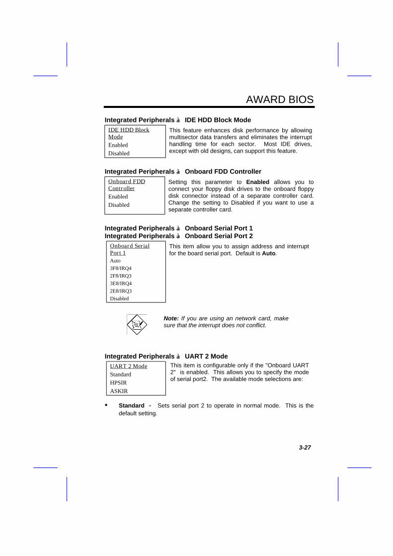
Integrated Peripherals à IDE HDD Block ModeIDE HDD BlockModeEnabledDisabled
This feature enhances disk performance by allowingmultisector data transfers and eliminates the interrupthandling time for each sector. Most IDE drives,except with old designs, can support this feature.
Integrated Peripherals à Onboard FDD ControllerOnboard FDDControllerEnabledDisabled
Setting this parameter to Enabled allows you toconnect your floppy disk drives to the onboard floppydisk connector instead of a separate controller card.Change the setting to Disabled if you want to use aseparate controller card.
Integrated Peripherals à Onboard Serial Port 1Integrated Peripherals à Onboard Serial Port 2
Onboard SerialPort 1Auto3F8/IRQ42F8/IRQ33E8/IRQ42E8/IRQ3Disabled
This item allow you to assign address and interruptfor the board serial port. Default is Auto.
Note: If you are using an network card, makesure that the interrupt does not conflict.
Integrated Peripherals à UART 2 ModeUART 2 ModeStandardHPSIRASKIR
This item is configurable only if the "Onboard UART2" is enabled. This allows you to specify the modeof serial port2. The available mode selections are:
• Standard - Sets serial port 2 to operate in normal mode. This is thedefault setting.

AWARD BIOS
3-28
• HPSIR - Select this setting if you installed an Infrared module in yoursystem via IrDA connector (refer to section 2.3 "Connectors"). Thissetting allows infrared serial communication at a maximum baud rate of115K baud.
• ASKIR - Select this setting if you installed an Infrared module via IrDAconnector (refer to section 2.3 "Connectors"). This setting allows infraredserial communication at a maximum baud rate of 19.2K baud.
Integrated Peripherals à IR Function DuplexIR Function DuplexFullHalf
This item lets you set the duplex mode for the IRcommunication. Full - Allows IR communication inbidirectional mode. Half - Allows IR communication insingle direction only.
Note: This option appears only if the IRfunction is activated and the Onboard UART 2Mode parameter is NOT set to Standard.
Integrated Peripherals à Onboard Parallel PortOnboard ParallelPort3BC/IRQ7378/IRQ7278/IRQ7Disabled
This item controls the onboard parallel port addressand interrupt.
Note: If you are using an I/O card with aparallel port, make sure that the addresses andIRQ do not conflict.
AWARD BIOS
3-29
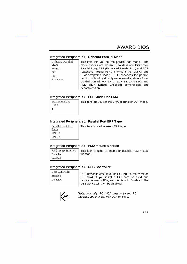
Integrated Peripherals à Onboard Parallel ModeOnboard ParallelModeNormalEPPECPECP + EPP
This item lets you set the parallel port mode. Themode options are Normal (Standard and BidirectionParallel Port), EPP (Enhanced Parallel Port) and ECP(Extended Parallel Port). Normal is the IBM AT andPS/2 compatible mode. EPP enhances the parallelport throughput by directly writing/reading data to/fromparallel port without latch. ECP supports DMA andRLE (Run Length Encoded) compression anddecompression.
Integrated Peripherals à ECP Mode Use DMAECP Mode UseDMA31
This item lets you set the DMA channel of ECP mode.
Integrated Peripherals à Parallel Port EPP TypeParallel Port EPPTypeEPP1.7EPP1.9
This item is used to select EPP type.
Integrated Peripherals à PS/2 mouse functionPS/2 mouse functionDisabledEnabled
This item is used to enable or disable PS/2 mousefunction.
Integrated Peripherals à USB ControllerUSB ControllerEnabledDisabled
USB device is default to use PCI INTD#, the same asPCI slot4. If you installed PCI card on slot4 andrequire to use INTD#, set this item to Disabled. TheUSB device will then be disabled.
Note: Normally, PCI VGA does not need PCIinterrupt, you may put PCI VGA on slot4.
AWARD BIOS
3-30
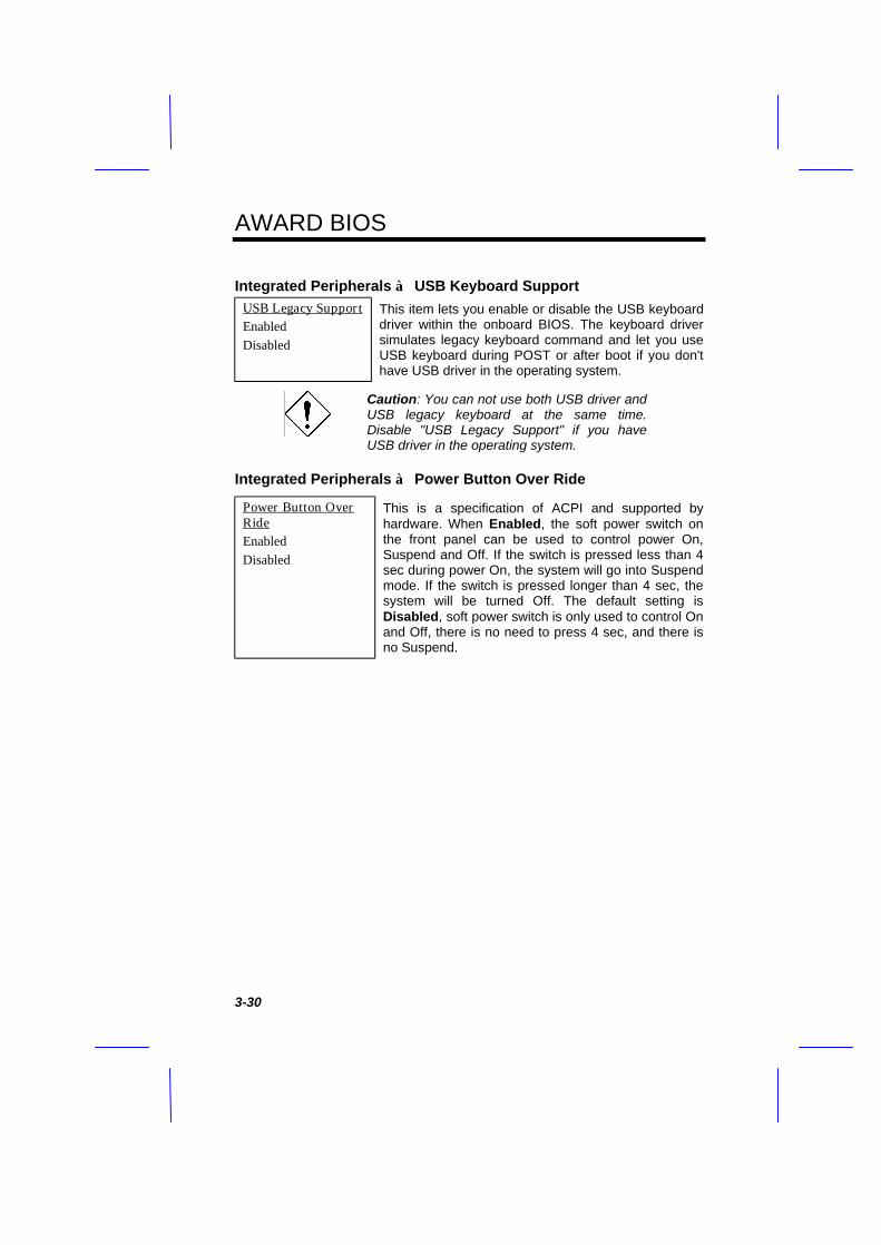
Integrated Peripherals à USB Keyboard SupportUSB Legacy SupportEnabledDisabled
This item lets you enable or disable the USB keyboarddriver within the onboard BIOS. The keyboard driversimulates legacy keyboard command and let you useUSB keyboard during POST or after boot if you don'thave USB driver in the operating system.
Caution: You can not use both USB driver andUSB legacy keyboard at the same time.Disable "USB Legacy Support" if you haveUSB driver in the operating system.
Integrated Peripherals à Power Button Over Ride
Power Button OverRideEnabledDisabled
This is a specification of ACPI and supported byhardware. When Enabled, the soft power switch onthe front panel can be used to control power On,Suspend and Off. If the switch is pressed less than 4sec during power On, the system will go into Suspendmode. If the switch is pressed longer than 4 sec, thesystem will be turned Off. The default setting isDisabled, soft power switch is only used to control Onand Off, there is no need to press 4 sec, and there isno Suspend.
AWARD BIOS
3-31
3.10 Password Setting
Password prevents unauthorized use of your computer. If you set a password,the system prompts for the correct password before boot or access to Setup.
To set a password:
1. At the prompt, type your password. Your password can be up to 8alphanumeric characters. When you type the characters, they appear asasterisks on the password screen box.
2. After typing the password, press.
3. At the next prompt, re-type your password and press again to confirm thenew password. After the password entry, the screen automatically revertsto the main screen.
To disable the password, press when prompted to enter the password. Thescreen displays a message confirming that the password has been disabled.
3.11 IDE HDD Auto Detection
If your system has an IDE hard drive, you can use this function to detect itsparameters and enter them into the "Standard CMOS Setup" automatically.
This routine only detects one set of parameters for your IDE hard drive. SomeIDE drives can use more than one set of parameters. If your hard disk isformatted using different parameters than those detected, you have to enter theparameters manually. If the parameters listed do not match the ones used toformat the disk, the information on that disk will not be accessible. If the auto-detected parameters displayed do not match those that used for your drive,ignore them. Type N to reject the values and enter the correct ones manuallyfrom the Standard CMOS Setup screen.
3.12 Save & Exit Setup
This function automatically saves all CMOS values before leaving Setup.

AWARD BIOS
3-32
3.13 Exit without Saving
Use this function to exit Setup without saving the CMOS value changes. Donot use this option if you want to save the new configuration.
3.14 NCR SCSI BIOS and Drivers
The NCR 53C810 SCSI BIOS resides in the same flash memory chip as thesystem BIOS. The onboard NCR SCSI BIOS is used to support NCR 53C810SCSI control card without BIOS code. The NCR SCSI BIOS directly supportsDOS, Windows 3.1 and OS/2. For better system performance, you may usethe drivers that come with the NCR SCSI card or with your operating system.For details, refer to the installation manual of your NCR 53C810 SCSI card.
3.15 BIOS Flash Utility
The BIOS Flash utility allows you to upgrade the system BIOS. To get theAOpen Flash utility and the upgrade BIOS file, contact your local distributor orvisit our homepage at http://www.aopen.com.tw. Please make sure that youhave the correct BIOS ready, the BIOS filename is normally likeMX58R110.BIN, which means model MX58 BIOS revision 1.10.
There are two useful programs, Checksum utility CHECKSUM.EXE and AOpenFlash utility AOFLASH.EXE. Follow the procedures below to upgrade yourBIOS.
[CHECKSUM.EXE]
This utility will help you to determine if the BIOS has been downloaded correctlyor not.
1. ExecuteC:> CHECKSUM Biosfile.bin
Biosfile.bin is the filename of the BIOS code. (for example, MX58R110.BIN)2. The utility will show "Checksum is ssss".

AWARD BIOS
3-33
3. Compare the "ssss" with original checksum posted on Web or BBS. If theyare different, please do not proceed any further and try to download theBIOS again.
[AOFLASH.EXE]
This utility will try to check the mainboard model, BIOS version and Super/UltraIO chip model. To ensure the correct BIOS file for the correct mainboard andIO chip. This utility will permanently replace your original BIOS content afterflashing.
1. Bootup DOS from floppy without loading any memory manager (HIMEM,EMM386, QEMM386, ...).
2. ExecuteC:> AOFLASH Biosfile.bin
Biosfile.bin is the filename of the BIOS code. (for example, MX58R110.BIN)3. After loading the new BIOS code, the utility will prompt you to save original
BIOS code into your HDD or floppy. Please press "Y" to store it as"BIOS.OLD".
4. After the old BIOS has been successfully saved, press "Y" to replace BIOS.5. DO NOT turn off the power during "FLASHING".6. Reboot the system by turn off the power after "FLASHING".7. Press "DEL" key to enter BIOS setup during POST.8. Reload the "BIOS SETUP DEFAULT" and reconfigure other items as
previous set.9. Save & Exit. Done!
Warning: DO NOT turn off the power during"FLASHING". If the BIOS programming is notsuccessfully finished, the system will not be bootagain, and you may need to physically replace theBIOS chip.
Tip: You may load back original BIOS "BIOS.OLD" bythe same procedure.