Embed Size (px)
Citation preview
Technical Manual
V2.0.3
08 April 2011
Allied Vision Technologies GmbHTaschenweg 2aD-07646 Stadtroda / Germany
AVT Guppy PRO
Guppy PRO Technical Manual V2.0.3
2
Legal noticeFor customers in the U.S.A.This equipment has been tested and found to comply with the limits for a Class B digital device, pursuant to Part 15 of the FCC Rules. These limits are designed to provide reasonable protection against harmful interference when the equipment is operated in a residential envi-ronment. This equipment generates, uses, and can radiate radio frequency energy and, if not installed and used in accordance with the instruction manual, may cause harmful interference to radio communications. However there is no guarantee that interferences will not occur in a particular installation. If the equipment does cause harmful interference to radio or televi-sion reception, the user is encouraged to try to correct the interference by one or more of the following measures:• Reorient or relocate the receiving antenna.• Increase the distance between the equipment and the receiver.• Use a different line outlet for the receiver.• Consult a radio or TV technician for help.
You are cautioned that any changes or modifications not expressly approved in this manual could void your authority to operate this equipment. The shielded interface cable recom-mended in this manual must be used with this equipment in order to comply with the limits for a computing device pursuant to Subpart B of Part 15 of FCC Rules.
For customers in CanadaThis apparatus complies with the Class B limits for radio noise emissions set out in the Radio Interference Regulations.
Pour utilisateurs au CanadaCet appareil est conforme aux normes classe B pour bruits radioélectriques, spécifiées dans le Règlement sur le brouillage radioélectrique.
Life support applicationsThese products are not designed for use in life support appliances, devices, or systems where malfunction of these products can reasonably be expected to result in personal injury. Allied customers using or selling these products for use in such applications do so at their own risk and agree to fully indemnify Allied for any damages resulting from such improper use or sale.
TrademarksMicrosoft, Windows, Windows 7, Windows Vista, and Windows XP are either registered trade-marks or trademarks of Microsoft Corporation in the United States and/or other countries.FireWire is a registered trademark of Apple Computers for the IEEE 1394 standard.IEEE 1394 standard is a trademark of the Institute of Electrical and Electronics Engineers, Inc. and licensed to the IEEE 1394 Standards Association.Apple is a trademark of Apple Inc., registered in the U.S. and other countries.Unless stated otherwise, all trademarks appearing in this document of Allied Vision Technologies are brands protected by law.
WarrantyThe information provided by Allied Vision Technologies is supplied without any guarantees or warranty whatsoever, be it specific or implicit. Also excluded are all implicit warranties con-cerning the negotiability, the suitability for specific applications or the non-breaking of laws and patents. Even if we assume that the information supplied to us is accurate, errors and inaccuracy may still occur.
CopyrightAll texts, pictures and graphics are protected by copyright and other laws protecting intellec-tual property. It is not permitted to copy or modify them for trade use or transfer, nor may they be used on web sites.
Allied Vision Technologies GmbH 04/2011All rights reserved.Managing Director: Mr. Frank GrubeTax ID: DE 184383113
Headquarters:
Taschenweg 2AD-07646 Stadtroda, GermanyTel.: +49 (0)36428 6770Fax: +49 (0)36428 677-28e-mail: [email protected]
Guppy PRO Technical Manual V2.0.3
3
Contents
Contacting Allied Vision Technologies ................................................... 9
Introduction ...........................................................................................................10Document history ......................................................................................................... 10Manual overview........................................................................................................... 13Conventions used in this manual..................................................................................... 14
Styles ..................................................................................................................... 14Symbols .................................................................................................................. 15
More information.......................................................................................................... 15Before operation .......................................................................................................... 16
Guppy PRO cameras .........................................................................................17
Conformity ..............................................................................................................18
FireWire ....................................................................................................................19Overview ..................................................................................................................... 19
Definition ............................................................................................................... 19IEEE 1394 standards ................................................................................................. 19Why use FireWire? .................................................................................................... 19
FireWire in detail .......................................................................................................... 20Serial bus................................................................................................................ 20FireWire connection capabilities ................................................................................. 21Capabilities of 1394a (FireWire 400)............................................................................ 22
IIDC V1.3 camera control standards ........................................................................ 22Capabilities of 1394b (FireWire 800) ........................................................................... 22
IIDC V1.31 camera control standards ...................................................................... 23Compatibility between 1394a and 1394b...................................................................... 23
Compatibility example .......................................................................................... 23Image transfer via 1394a and 1394b ........................................................................... 241394b bandwidths.................................................................................................... 25
Requirements for PC and 1394b.............................................................................. 25Requirements for laptop and 1394b ........................................................................ 26Example 1: 1394b bandwidth of Guppy PRO cameras.................................................. 28Example 2: More than one Guppy PRO camera at full speed ........................................ 28
FireWire Plug & play capabilities................................................................................. 29FireWire hot-plug and screw-lock precautions ............................................................... 29Operating system support .......................................................................................... 30
Filter and lenses .................................................................................................31IR cut filter: spectral transmission .................................................................................. 31Camera lenses .............................................................................................................. 32
Specifications .......................................................................................................35Guppy PRO F-031B/C ..................................................................................................... 35
Guppy PRO Technical Manual V2.0.3
4
Guppy PRO F-032B/C ..................................................................................................... 37Guppy PRO F-125B/C ..................................................................................................... 39Guppy PRO F-146B/C ..................................................................................................... 41Guppy PRO F-201B/C ..................................................................................................... 43Guppy PRO F-503B/C ..................................................................................................... 45Spectral sensitivity ....................................................................................................... 47
Camera dimensions ..........................................................................................54Guppy PRO standard housing (1 x 1394b copper)............................................................... 54Tripod adapter ............................................................................................................. 55Cross section: C-Mount .................................................................................................. 56Adjustment of C-Mount.................................................................................................. 57
Camera interfaces .............................................................................................58IEEE 1394b port pin assignment ..................................................................................... 58Camera I/O connector pin assignment ............................................................................. 59Status LEDs.................................................................................................................. 60
Normal conditions .................................................................................................... 61Error conditions ....................................................................................................... 61
Control and video data signals........................................................................................ 63Inputs .................................................................................................................... 63
Triggers.............................................................................................................. 63Input/output pin control........................................................................................... 64
IO_INP_CTRL 1 .................................................................................................... 65Trigger delay ....................................................................................................... 66
Outputs .................................................................................................................. 68IO_OUTP_CTRL 1-3 ............................................................................................... 70Output modes...................................................................................................... 71
Pulse-width modulation ............................................................................................ 73PWM: minimal and maximal periods and frequencies ................................................. 74PWM: Examples in practice .................................................................................... 75
Pixel data.................................................................................................................... 76Description of video data formats ............................................................................... 77
Description of the data path........................................................................82Block diagrams of the cameras ....................................................................................... 82
Black and white cameras ........................................................................................... 82Color cameras .......................................................................................................... 83
White balance .............................................................................................................. 84One-push white balance ............................................................................................ 86Auto white balance (AWB)......................................................................................... 88
Auto shutter ................................................................................................................ 89Auto gain .................................................................................................................... 91Manual gain................................................................................................................. 94Brightness (black level or offset) .................................................................................... 94Mirror function (only Guppy PRO F-503) ........................................................................... 96Look-up table (LUT) and gamma function......................................................................... 97
Loading an LUT into the camera ................................................................................. 99
Guppy PRO Technical Manual V2.0.3
5
Defect pixel correction(only Guppy PRO F-503B/C).......................................................................................... 100
Building defect pixel data ....................................................................................... 102Grab an image with defect pixel data .................................................................... 103Calculate defect pixel coordinates ........................................................................ 103Reset values (resolution, shutter, gain, brightness) ................................................ 103
Activate/deactivate defect pixel correction ................................................................ 104Store defect pixel data non-volatile .......................................................................... 104Load non-volatile stored defect pixel data ................................................................. 104Send defect pixel data to the host ............................................................................ 104Receive defect pixel data from the host ..................................................................... 104
Binning (only b/w cameras; F-503: also color cameras) .................................................... 1052 x binning (F-503 also 4 x) .................................................................................... 105Vertical binning ..................................................................................................... 106Horizontal binning ................................................................................................. 1092 x full binning (F-503 also 4 x full binning) .............................................................. 111
Sub-sampling (only F-503B/C and CCD cameras b/w)........................................................ 113What is sub-sampling? ............................................................................................ 113Which Guppy PRO models have sub-sampling? ............................................................ 113Description of sub-sampling..................................................................................... 113
Binning and sub-sampling access (F-503 only)................................................................ 118Packed 12-Bit Mode .................................................................................................... 121Color interpolation (BAYER demosaicing) ....................................................................... 122Hue and saturation ..................................................................................................... 123Color correction.......................................................................................................... 124
Why color correction? ......................................................................................... 124Color correction in AVT cameras ........................................................................... 124Color correction: formula..................................................................................... 124GretagMacbeth ColorChecker ................................................................................ 124Changing color correction coefficients .................................................................. 125Switch color correction on/off ............................................................................. 125
Color conversion (RGB to YUV)...................................................................................... 126Bulk Trigger ............................................................................................................... 126Level Trigger.............................................................................................................. 126
Controlling image capture ..........................................................................127Global shutter (CCD cameras only)................................................................................. 127Electronic rolling shutter (ERS) and global reset release shutter (GRR) (only Guppy PRO F-503) .... 128Trigger modes ............................................................................................................ 129
Trigger_Mode_0 (edge mode) and Trigger_Mode_1 (level mode).................................... 130Guppy PRO F-503, Trigger_Mode_0, electronic rolling shutter ................................... 131Guppy PRO F-503, Trigger_Mode_0, global reset release shutter ................................ 133
Bulk trigger (Trigger_Mode_15) ................................................................................ 134Trigger delay ......................................................................................................... 137
Trigger delay advanced register............................................................................ 138Software trigger ..................................................................................................... 139Debounce.............................................................................................................. 139Debounce time....................................................................................................... 140
Guppy PRO Technical Manual V2.0.3
6
Exposure time (shutter) and offset ................................................................................ 141Exposure time of Guppy PRO F-503 (CMOS)................................................................. 141Exposure time offset ............................................................................................... 141Minimum exposure time .......................................................................................... 142Extended shutter.................................................................................................... 142
One-shot ................................................................................................................... 144One-shot command on the bus to start of exposure ..................................................... 145End of exposure to first packet on the bus ................................................................. 146
Multi-shot ................................................................................................................. 147ISO_Enable / free-run.................................................................................................. 147Asynchronous broadcast .............................................................................................. 147Jitter at start of exposure ............................................................................................ 148
Video formats, modes and bandwidth .................................................150Guppy PRO F-031B / Guppy PRO F-031C.......................................................................... 151Guppy PRO F-032B / Guppy PRO F-032C.......................................................................... 153Guppy PRO F-125B / Guppy PRO F-125C.......................................................................... 155Guppy PRO F-146B / Guppy PRO F-146C.......................................................................... 157Guppy PRO F-201B / Guppy PRO F-201C.......................................................................... 159Guppy PRO F-503B / Guppy PRO F-503C.......................................................................... 161Area of interest (AOI) ................................................................................................. 163
Autofunction AOI ................................................................................................... 165Frame rates................................................................................................................ 166
Frame rates Format_7 ............................................................................................. 170Guppy PRO F-031: AOI frame rates ............................................................................ 171Guppy PRO F-032: AOI frame rates ............................................................................ 172Guppy PRO F-125: AOI frame rates ............................................................................ 173Guppy PRO F-146: AOI frame rates ............................................................................ 174Guppy PRO F-201: AOI frame rates ............................................................................ 175Guppy PRO F-503: AOI frame rates ............................................................................ 176
How does bandwidth affect the frame rate? ...................................178Example formula for the b/w camera..................................................................... 179
Test images ............................................................................................................... 180Loading test images ............................................................................................... 180Test images for b/w cameras.................................................................................... 180Test images for color cameras .................................................................................. 181
YUV4:2:2 mode.................................................................................................. 181Mono8 (raw data) .............................................................................................. 181
Configuration of the camera......................................................................182Camera_Status_Register............................................................................................... 182
Example................................................................................................................ 183Sample program ..................................................................................................... 185
Example FireGrab ............................................................................................... 185Example FireStack API ........................................................................................ 186
Configuration ROM...................................................................................................... 187Implemented registers (IIDC V1.31) .............................................................................. 190
Camera initialize register......................................................................................... 190
Guppy PRO Technical Manual V2.0.3
7
Inquiry register for video format............................................................................... 190Inquiry register for video mode ................................................................................ 191Inquiry register for video frame rate and base address ................................................. 192Inquiry register for basic function............................................................................. 201Inquiry register for feature presence ......................................................................... 202Inquiry register for feature elements ......................................................................... 204Status and control registers for camera...................................................................... 207Inquiry register for absolute value CSR offset address .................................................. 208Status and control register for one-push .................................................................... 209Feature control error status register .......................................................................... 212Video mode control and status registers for Format_7.................................................. 213
Quadlet offset Format_7 Mode_0 .......................................................................... 213Quadlet offset Format_7 Mode_1 .......................................................................... 213Format_7 control and status register (CSR) ............................................................ 213
Advanced features (AVT-specific) .................................................................................. 215Advanced registers summary .................................................................................... 215Extended version information register ....................................................................... 217Advanced feature inquiry......................................................................................... 220Camera status ........................................................................................................ 222Maximum resolution ............................................................................................... 223Time base ............................................................................................................. 223Extended shutter.................................................................................................... 225Test images ........................................................................................................... 226Look-up tables (LUT) .............................................................................................. 227
Loading a look-up table into the camera ............................................................... 228Defect pixel correction ............................................................................................ 229Input/output pin control......................................................................................... 231Delayed Integration Enable (IntEna) ......................................................................... 232Auto shutter control ............................................................................................... 233Auto gain control ................................................................................................... 234Autofunction AOI ................................................................................................... 235Color correction ..................................................................................................... 236Trigger delay ......................................................................................................... 237Mirror image.......................................................................................................... 237Soft reset.............................................................................................................. 238Maximum ISO packet size ........................................................................................ 239Format_7 mode mapping(only Guppy PRO F-503) .......................................................................................... 241
Example ........................................................................................................... 242Low-noise binning mode (2 x and 4 x binning)(only Guppy PRO F-503) .......................................................................................... 242Software feature control (disable LED)....................................................................... 243
Disable LEDs...................................................................................................... 243User profiles .......................................................................................................... 244
Error codes ....................................................................................................... 245Reset of error codes ........................................................................................... 246Stored settings .................................................................................................. 246
Pulse-width modulation (PWM)................................................................................. 247Global reset release shutter(only Guppy PRO F-503) .......................................................................................... 247

Guppy PRO Technical Manual V2.0.3
8
GPDATA_BUFFER..................................................................................................... 248Little endian vs. big endian byte order.................................................................. 248
Firmware update...............................................................................................250Extended version number (FPGA/µC).............................................................................. 250
Appendix ................................................................................................................251Sensor position accuracy of AVT Guppy PRO cameras ........................................................ 251
Index.........................................................................................................................252
Contacting Allied Vision Technologies
Guppy PRO Technical Manual V2.0.3
9
Contacting Allied Vision Technologies
Info
• Technical information:
http://www.alliedvisiontec.com
• Support:[email protected]
Allied Vision Technologies GmbH (Headquarters)Taschenweg 2a07646 Stadtroda, GermanyTel.: +49 36428-677-0Fax.: +49 36428-677-28e-mail: [email protected]
Allied Vision Technologies Canada Inc.101-3750 North Fraser WayBurnaby, BC, V5J 5E9, CanadaTel: +1 604-875-8855Fax: +1 604-875-8856e-mail: [email protected]
Allied Vision Technologies Inc.38 Washington StreetNewburyport, MA 01950, USAToll Free number +1-877-USA-1394Tel.: +1 978-225-2030Fax: +1 978-225-2029e-mail: [email protected]
Allied Vision Technologies Asia Pte. Ltd.82 Playfair Road#07-02 D’LithiumSingapore 368001Tel: +65 6634-9027Fax: +65 6634-902e-mail: [email protected]
Introduction
Guppy PRO Technical Manual V2.0.3
10
Introduction
This AVT Guppy PRO Technical Manual describes in depth the technical specifications, dimensions, all camera features (IIDC standard and AVT smart features) and their registers, trigger features, all video and color formats, bandwidth and frame rate calculation.
For information on hardware installation, safety warnings, pin assignments on I/O connectors and 1394b connectors read the Hardware Installation Guide.
Document history
Note
Please read through this manual carefully.
We assume that you have read already the Hardware Installation Guide and that you have installed the hard-ware and software on your PC or laptop (FireWire card, cables).
Version Date Remarks
V2.0.1 30.11.10 New Manual — RELEASE status
to be continued on next page
Table 1: Document history
Introduction
Guppy PRO Technical Manual V2.0.3
11
continued from last page
V2.0.2 05.04.11 • Revised video formats of Guppy PRO F-503 Table 76: Video Format_7 default modes Guppy PRO F-503B / F-503C on page 162
• Added exposure time offset for Guppy PRO F-503 Table 58: Camera-specific exposure time offset on page 141
• Added On request: power out 6 W (HIROSE) in all specification tables: see Chapter Specifications on page 35 to 46
• Revised advanced register: input control (only one input) in Table 20: Advanced register: Input control on page 64
• Revised IO_INP_CTRL: ID 0x3..0x1F is Reserved in Table 21: Input routing on page 65
• Revised advanced register: output control (3 outputs) in Table 26: Advanced register: Output control on page 70
• At register 0xF1000200 changed width and height: see Table 114: Advanced register: Maximum resolution inquiry on page 223
• YUV8: deleted description of data type straight binary: Figure 32: Data structure of YUV8; Source: IIDC V1.31 on page 80
• Y (Mono8/Raw8) are AVT own formats:see Table 33: Y (Mono8) format: Source: IIDC V1.31 / Y (Raw8) format: AVT on page 78
to be continued on next page
Version Date Remarks
Table 1: Document history
Introduction
Guppy PRO Technical Manual V2.0.3
12
continued from last page
[continued]
V2.0.2
[continued]
05.04.11
• Video data formats now with subscript letters instead of underscore as wrongly used in IIDC, see Chapter Description of video data formats on page 77
• Revised spectral sensitivity for Guppy PRO F-031C: see Figure 10: Spectral sensitivity of Guppy PRO F-031C (without IR cut filter) on page 48
• Defect pixel correction: you don’t need to set value for brightness to max. any more: see Figure 43: Defect pixel correction: build and store on page 102 and Chapter Grab an image with defect pixel data on page 103
• Max. resolution of Guppy PRO F-503B/C changed from 2592 x 1944 to 2588 x 1940:see Chapter Guppy PRO F-503B/C on page 45 and Chapter Video Format_7 default modes Guppy PRO F-503B / F-503C on page 162
• Added Guppy PRO F-503 frame rate and bandwidth: see Table 4: Bandwidth of Guppy PRO cameras on page 28
• Changed max. resolution of Guppy PRO F-503 from 2592 x 1944 to 2588 x 1940: see Chapter Guppy PRO F-503B/C on page 45
• Guppy PRO F-503: Mono8, YUV411 and YUV422 now in all F7 modes available: see Chapter Guppy PRO F-503B/C on page 45
• Guppy PRO F-503: added minimum exposure time in Table 59: Camera-specific minimum exposure time on page 142
• Guppy PRO F-503: added shutter speed at full resolution: see Chapter Guppy PRO F-503B/C on page 45
• Guppy PRO F-503: added shutter speed: see Chapter Guppy PRO F-503B/C on page 45
• Guppy PRO F-503: binning and sub-sampling in all F7 modes for b/w and color models: see Chapter Guppy PRO F-503B/C on page 45
• Guppy PRO F-503: added 800 Mbit/s: see Chapter Guppy PRO F-503B/C on page 45
• Guppy PRO F-503: added exposure time for long-term integration (extended shutter) up to 22 seconds: see Chapter Extended shutter on page 142
• Guppy PRO F-503: Revised chapter Chapter Mirror function (only Guppy PRO F-503) on page 96
to be continued on next page
Version Date Remarks
Table 1: Document history
Introduction
Guppy PRO Technical Manual V2.0.3
13
Manual overview
This manual overview describes each chapter of this manual shortly.• Chapter Contacting Allied Vision Technologies on page 9 lists AVT con-
tact data for both:– technical information / ordering– commercial information
• Chapter Introduction on page 10 (this chapter) gives you the document history, a manual overview and conventions used in this manual (styles and symbols). Furthermore you learn how to get more information on how to install hardware (Hardware Installation Guide), available AVT software (incl. documentation) and where to get it.
• Chapter Guppy PRO cameras on page 17 gives you a short introduction to the Guppy PRO cameras with their FireWire technology. Links are pro-vided to data sheets and brochures on AVT website.
• Chapter Conformity on page 18 gives you information about conformity of AVT cameras.
• Chapter FireWire on page 19 describes the FireWire standard in detail, explains the compatibility between 1394a and 1394b and explains bandwidth details (incl. Guppy PRO examples).– Read and follow the FireWire hot-plug and screw-lock precau-
tions in Chapter FireWire hot-plug and screw-lock precautions on page 29.
– Read Chapter Operating system support on page 30.• Chapter Filter and lenses on page 31 describes the IR cut filter and suit-
able camera lenses.• Chapter Specifications on page 35 lists camera details and spectral sen-
sitivity diagrams for each camera type.• Chapter Camera dimensions on page 54 provides CAD drawings of stan-
dard housing (copper and GOF) models, tripod adapter, available angled head models, cross sections of CS-Mount and C-Mount.
continued from last page
[continued]
V2.0.2
[continued]
05.04.11
• Guppy PRO F-503: manual gain range now 8 ... 48 (instead of 60): see Chapter Manual gain on page 94
• Guppy PRO F-503: manual gain range in db now 0 ... 18 dB (instead of 26 dB): see Chapter Guppy PRO F-503B/C on page 45
V2.0.3 08.04.11 • Revised Chapter Binning (only b/w cameras; F-503: also color cameras) on page 105
Version Date Remarks
Table 1: Document history
Introduction
Guppy PRO Technical Manual V2.0.3
14
• Chapter Camera interfaces on page 58 describes in detail the inputs/outputs of the cameras (incl. Trigger features). For a general description of the interfaces (FireWire and I/O connector) see Hardware Installa-tion Guide.
• Chapter Description of the data path on page 82 describes in detail IIDC conform as well as AVT-specific camera features.
• Chapter Controlling image capture on page 127 describes trigger modes, exposure time, one-shot/multi-shot/ISO_Enable features.
• Chapter Video formats, modes and bandwidth on page 150 lists all avail-able fixed and Format_7 modes (incl. color modes, frame rates, binning/sub-sampling, AOI=area of interest).
• Chapter How does bandwidth affect the frame rate? on page 178 gives some considerations on bandwidth details.
• Chapter Configuration of the camera on page 182 lists standard and advanced register descriptions of all camera features.
• Chapter Firmware update on page 250 explains where to get information on firmware updates and explains the extended version number scheme of FPGA/µC.
• Chapter Appendix on page 251 lists the sensor position accuracy of AVT cameras.
• Chapter Index on page 252 gives you quick access to all relevant data in this manual.
Conventions used in this manual
To give this manual an easily understood layout and to emphasize important information, the following typographical styles and symbols are used:
Styles
Style Function Example
Bold Programs, inputs or highlighting important things
bold
Courier Code listings etc. Input
Upper case Register REGISTER
Italics Modes, fields Mode
Parentheses and/or blue Links (Link)
Table 2: Styles
Introduction
Guppy PRO Technical Manual V2.0.3
15
Symbols
More information
For more information on hardware and software read the following:• Hardware Installation Guide describes the hardware installation proce-
dures for all 1394 AVT cameras (Oscar, Marlin, Guppy, Pike, Stingray, Guppy PRO). Additionally you get safety instructions and information about camera interfaces (IEEE 1394a/b copper and GOF, I/O connectors, input and output).
Note
This symbol highlights important information.
Caution
This symbol highlights important instructions. You have to follow these instructions to avoid malfunctions.
www
This symbol highlights URLs for further information. The URL itself is shown in blue.
Example:
http://www.alliedvisiontec.com
www
For downloading the Hardware Installation Guide go to:
http://www.alliedvisiontec.com/emea/support/downloads/product-literature.html
There is no product CD.
www
All software packages (including documentation and release notes) provided by AVT can be downloaded at:
http://www.alliedvisiontec.com/emea/products/software.html
All software packages are also on AVT’s product CD.
Introduction
Guppy PRO Technical Manual V2.0.3
16
Before operation
We place the highest demands for quality on our cameras.
Target group This Technical Manual is the guide to detailed technical information of the camera and is written for experts.
Getting started For a quick guide how to get started read Hardware Installation Guide first.
Note
Please read through this manual carefully before operating the camera.
For information on AVT accessories and AVT software read Hardware Installation Guide.
Caution
Before operating any AVT camera read safety instructions and ESD warnings in Hardware Installation Guide.
www
To demonstrate the properties of the camera, you find some samples on SmartView which is part of AVT FirePackage. A free version is available for download at:
http://www.alliedvisiontec.com/emea/products/software.html
Note
The camera also works with all IIDC (formerly DCAM) compatible IEEE 1394 programs and image processing libraries.
Guppy PRO cameras
Guppy PRO Technical Manual V2.0.3
17
Guppy PRO cameras
Guppy PRO With Guppy PRO cameras, entry into the world of digital image processing is simpler and more cost-effective than ever before. Guppy PRO cameras are the smallest 1394b cameras worldwide.
IEEE 1394b With the new Guppy PRO, Allied Vision Technologies presents a wide range of cameras with IEEE 1394b interfaces.
Image applications Allied Vision Technologies can provide users with a range of products that meet almost all the requirements of a very wide range of image applications.
FireWire The industry standard IEEE 1394 (FireWire or i.Link) facilitates the simplest computer compatibility and bidirectional data transfer. Further development of the IEEE 1394 standard has already made 800 Mbit/second possible. Investment in this standard is therefore secure for the future; each further development takes into account compatibility with the preceding standard, and vice versa, meaning that IEEE 1394b is backward-compatible with IEEE 1394a. Your applications will grow as technical progress advances.
Note
For further information on FireWire read Chapter FireWire on page 19.
www
For further information on the highlights of Guppy PRO types, the Guppy PRO family and the whole range of AVT FireWire cameras read the data sheets and brochures on the website of Allied Vision Technologies:
www.alliedvisiontec.com
Conformity
Guppy PRO Technical Manual V2.0.3
18
ConformityAllied Vision Technologies declares under its sole responsibility that all stan-dard cameras of the AVT Guppy PRO family to which this declaration relates are in conformity with the following standard(s) or other normative docu-ment(s):• CE, following the provisions of 2004/108/EG directive• FCC Part 15 Class B• RoHS (2002/95/EC)
CE
We declare, under our sole responsibility, that the previously described AVT Guppy PRO cameras conform to the directives of the CE.
FCC – Class B Device
Note: This equipment has been tested and found to comply with the limits for a Class B digital device, pursuant to part 15 of the FCC Rules. These limits are designed to provide reasonable protection against harmful interference in a residential environment. This equipment generates, uses, and can radi-ate radio frequency energy and, if not installed and used in accordance with the instructions, may cause harmful interference to radio communications. Operation of this equipment in a residential area is likely to cause harmful interference in which case the user will be required to correct the interfer-ence at his own expense. You are cautioned that any changes or modifica-tions not expressly approved in this manual could void your authority to operate this equipment.
FireWire
Guppy PRO Technical Manual V2.0.3
19
FireWire
Overview
FireWire provides one of the most comprehensive, high-performance, cost-effective solutions platforms. FireWire offers very impressive throughput at very affordable prices.
DefinitionFireWire (also known as i.Link or IEEE 1394) is a personal computer and digital video serial bus interface standard, offering high-speed communica-tions and isochronous real-time data services. FireWire has low implemen-tation costs and a simplified and adaptable cabling system.
IEEE 1394 standardsFireWire was developed by Apple Computer in the late 1990s, after work defining a slower version of the interface by the IEEE 1394 working commit-tee in the 1980s. Apple's development was completed in 1995. It is defined in IEEE standard 1394 which is currently a composite of three documents:• the original IEEE Std. 1394-1995• the IEEE Std. 1394a-2000 amendment• the IEEE Std. 1394b-2002 amendment
FireWire is used to connect digital cameras, especially in industrial systems for machine vision.
Why use FireWire?Digital cameras with on-board FireWire (IEEE 1394a or 1394b) communica-tions conforming to the IIDC standard (V1.3 or V1.31) have created cost-effective and powerful solutions options being used for thousands of differ-ent applications around the world. FireWire is currently the premier robust digital interface for industrial applications for many reasons, including:• Guaranteed bandwidth features to ensure fail-safe communications• Interoperability with multiple different camera types and vendors
Figure 1: FireWire Logo
FireWire
Guppy PRO Technical Manual V2.0.3
20
• Diverse camera powering options, including single-cable solutions up to 45 W
• Effective multiple-camera solutions• Large variety of FireWire accessories for industrial applications• Availability of repeaters and optical fibre cabling• Forwards and backward compatibility blending 1394a and 1394b• Both real-time (isochronous) and demand-driven asynchronous data
transmission capabilities
FireWire in detail
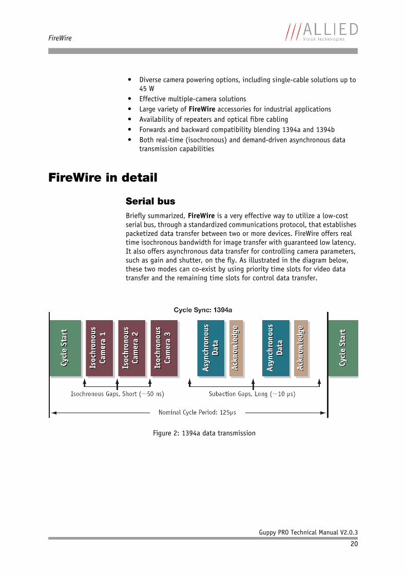
Serial busBriefly summarized, FireWire is a very effective way to utilize a low-cost serial bus, through a standardized communications protocol, that establishes packetized data transfer between two or more devices. FireWire offers real time isochronous bandwidth for image transfer with guaranteed low latency. It also offers asynchronous data transfer for controlling camera parameters, such as gain and shutter, on the fly. As illustrated in the diagram below, these two modes can co-exist by using priority time slots for video data transfer and the remaining time slots for control data transfer.
Figure 2: 1394a data transmission
FireWire
Guppy PRO Technical Manual V2.0.3
21
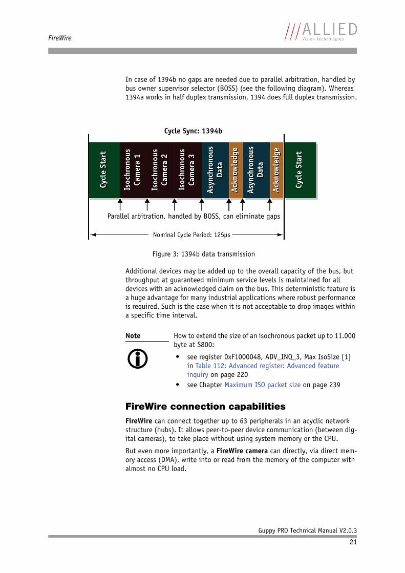
In case of 1394b no gaps are needed due to parallel arbitration, handled by bus owner supervisor selector (BOSS) (see the following diagram). Whereas 1394a works in half duplex transmission, 1394 does full duplex transmission.
Additional devices may be added up to the overall capacity of the bus, but throughput at guaranteed minimum service levels is maintained for all devices with an acknowledged claim on the bus. This deterministic feature is a huge advantage for many industrial applications where robust performance is required. Such is the case when it is not acceptable to drop images within a specific time interval.
FireWire connection capabilitiesFireWire can connect together up to 63 peripherals in an acyclic network structure (hubs). It allows peer-to-peer device communication (between dig-ital cameras), to take place without using system memory or the CPU.
But even more importantly, a FireWire camera can directly, via direct mem-ory access (DMA), write into or read from the memory of the computer with almost no CPU load.
Figure 3: 1394b data transmission
Note
How to extend the size of an isochronous packet up to 11.000 byte at S800:
• see register 0xF1000048, ADV_INQ_3, Max IsoSize [1] in Table 112: Advanced register: Advanced feature inquiry on page 220
• see Chapter Maximum ISO packet size on page 239
Cycle Sync: 1394b
Parallel arbitration, handled by BOSS, can eliminate gaps
FireWire
Guppy PRO Technical Manual V2.0.3
22
FireWire also supports multiple hosts per bus. FireWire requires only a cable with the correct number of pins on either end (normally 6 or 9). It is designed to support plug-and-play and hot swapping. It can supply up to 45 W of power per port at 30 V, allowing high consumption devices to oper-ate without a separate power cord.
Capabilities of 1394a (FireWire 400)FireWire 400 (S400) is able to transfer data between devices at 100, 200 or 400 MBit/s data rates. Although USB 2.0 claims to be capable of higher speeds (480 Mbit/s), FireWire is, in practice, not slower than USB 2.0.
The 1394a capabilities in detail:• 400 Mbit/s• Hot-pluggable devices• Peer-to-peer communications• Direct Memory Access (DMA) to host memory• Guaranteed bandwidth• Multiple devices (up to 45 W) powered via FireWire bus
IIDC V1.3 camera control standards
IIDC V1.3 released a set of camera control standards via 1394a which estab-lished a common communications protocol on which most current FireWire cameras are based.
In addition to common standards shared across manufacturers, a special Format_7 mode also provided a means by which a manufacturer could offer special features (smart features), such as:• higher resolutions• higher frame rates• diverse color modes
as extensions (advanced registers) to the prescribed common set.
Capabilities of 1394b (FireWire 800)FireWire 800 (S800) was introduced commercially by Apple in 2003 and has a 9-pin FireWire 800 connector (see details in Hardware Installation Guide and in Chapter IEEE 1394b port pin assignment on page 58). This newer 1394b specification allows a transfer rate of 800 MBit/s with backward com-patibilities to the slower rates and 6-pin connectors of FireWire 400.
Caution
While supplying such an amount of bus power is clearly a beneficial feature, it is very important not to exceed the inrush current of 18 mJoule in 3 ms.
Higher inrush current may damage the Phy chip of the camera and/or the Phy chip in your PC.
FireWire
Guppy PRO Technical Manual V2.0.3
23
The 1394b capabilities in detail:• 800 Mbit/s• All previous benefits of 1394a (see above)• Interoperability with 1394a devices• Longer communications distances (up to 500 m using GOF cables)
IIDC V1.31 camera control standards
Twinned with 1394b, the IIDC V1.31 standard arrived in January 2004, evolv-ing the industry standards for digital imaging communications to includeI/O and RS232 handling, and adding further formats. At such high band-widths it has become possible to transmit high-resolution images to the PC’s memory at very high frame rates.
Compatibility between 1394a and 1394b
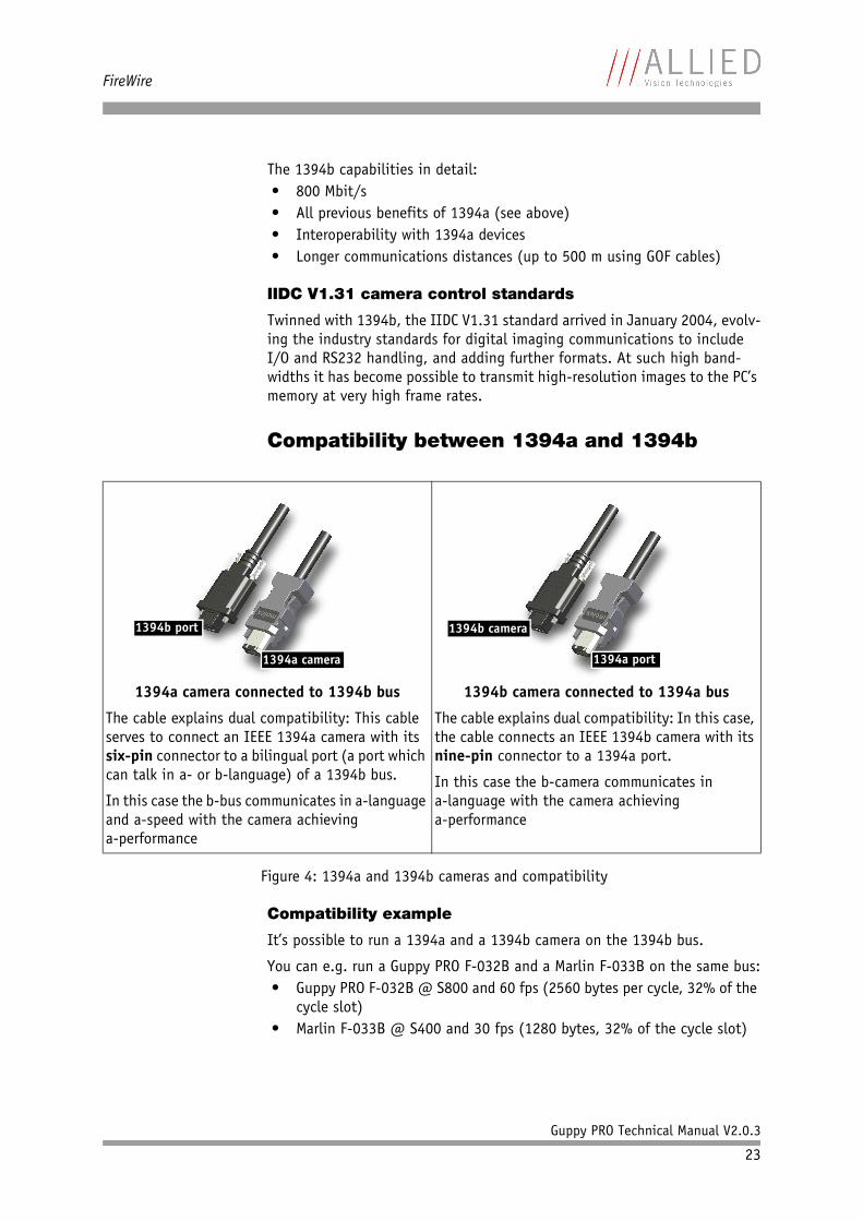
Compatibility example
It’s possible to run a 1394a and a 1394b camera on the 1394b bus.
You can e.g. run a Guppy PRO F-032B and a Marlin F-033B on the same bus:• Guppy PRO F-032B @ S800 and 60 fps (2560 bytes per cycle, 32% of the
cycle slot)• Marlin F-033B @ S400 and 30 fps (1280 bytes, 32% of the cycle slot)
1394a camera connected to 1394b bus
The cable explains dual compatibility: This cable serves to connect an IEEE 1394a camera with its six-pin connector to a bilingual port (a port which can talk in a- or b-language) of a 1394b bus.
In this case the b-bus communicates in a-language and a-speed with the camera achievinga-performance
1394b camera connected to 1394a bus
The cable explains dual compatibility: In this case, the cable connects an IEEE 1394b camera with its nine-pin connector to a 1394a port.
In this case the b-camera communicates ina-language with the camera achievinga-performance
Figure 4: 1394a and 1394b cameras and compatibility
1394b port
1394a camera 1394a port
1394b camera
FireWire
Guppy PRO Technical Manual V2.0.3
24
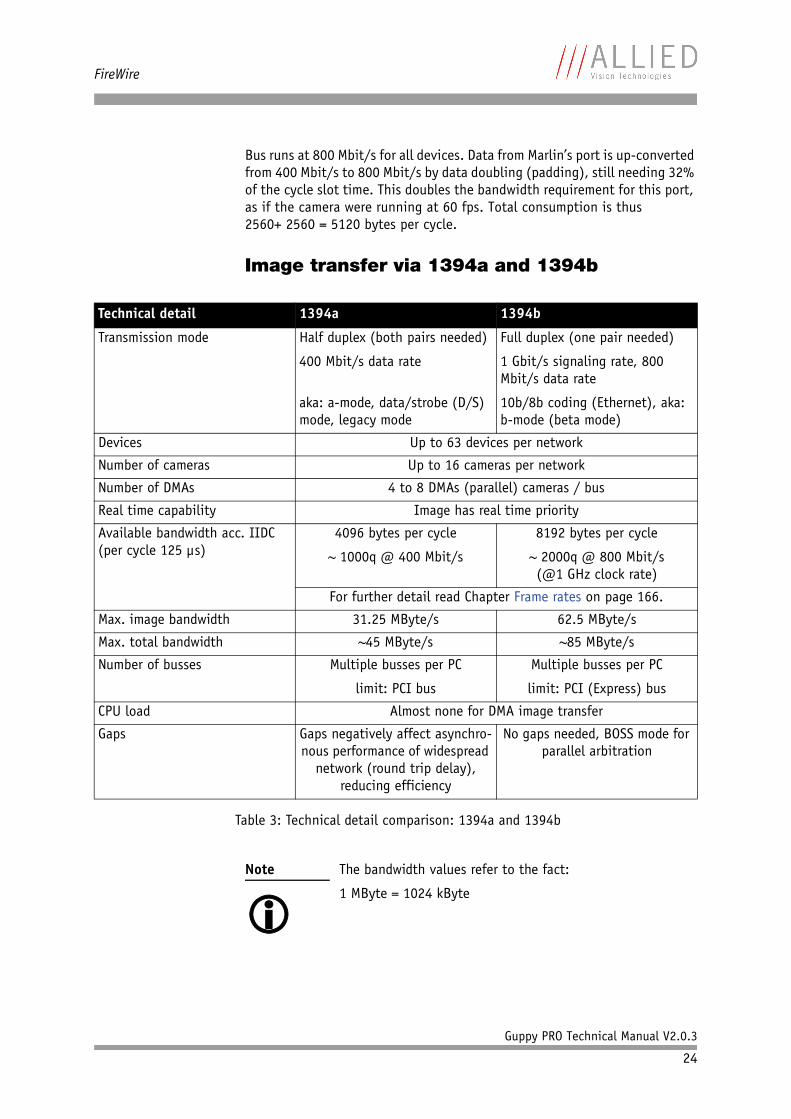
Bus runs at 800 Mbit/s for all devices. Data from Marlin’s port is up-converted from 400 Mbit/s to 800 Mbit/s by data doubling (padding), still needing 32% of the cycle slot time. This doubles the bandwidth requirement for this port, as if the camera were running at 60 fps. Total consumption is thus2560+ 2560 = 5120 bytes per cycle.
Image transfer via 1394a and 1394b
Technical detail 1394a 1394b
Transmission mode Half duplex (both pairs needed)
400 Mbit/s data rate
aka: a-mode, data/strobe (D/S) mode, legacy mode
Full duplex (one pair needed)
1 Gbit/s signaling rate, 800 Mbit/s data rate
10b/8b coding (Ethernet), aka: b-mode (beta mode)
Devices Up to 63 devices per network
Number of cameras Up to 16 cameras per network
Number of DMAs 4 to 8 DMAs (parallel) cameras / bus
Real time capability Image has real time priority
Available bandwidth acc. IIDC (per cycle 125 µs)
4096 bytes per cycle
~ 1000q @ 400 Mbit/s
8192 bytes per cycle
~ 2000q @ 800 Mbit/s(@1 GHz clock rate)
For further detail read Chapter Frame rates on page 166.
Max. image bandwidth 31.25 MByte/s 62.5 MByte/s
Max. total bandwidth ~45 MByte/s ~85 MByte/s
Number of busses Multiple busses per PC
limit: PCI bus
Multiple busses per PC
limit: PCI (Express) bus
CPU load Almost none for DMA image transfer
Gaps Gaps negatively affect asynchro-nous performance of widespread
network (round trip delay), reducing efficiency
No gaps needed, BOSS mode for parallel arbitration
Table 3: Technical detail comparison: 1394a and 1394b
Note
The bandwidth values refer to the fact:
1 MByte = 1024 kByte
FireWire
Guppy PRO Technical Manual V2.0.3
25
1394b bandwidthsAccording to the 1394b specification on isochronous transfer, the largest recommended data payload size is 8192 bytes per 125 µs cycle at a band-width of 800 Mbit/s.
For further details read Chapter How does bandwidth affect the frame rate? on page 178.
Requirements for PC and 1394b
One Guppy PRO camera connected to a PC’s 1394b bus can saturate the stan-dard PCI bus.
1394b also requires low latency for data transmission (due to small receive-FIFO). In order to get the most out of your camera-to-PC configuration, we recommend the following chipsets for your PC:• For Intel-based desktops, chipset 945 (or higher)• For non-Intel based desktops (e.g. AMD), PCI Express compatible chip-
set
For multi-camera applications one of the following bus cards is needed:• PCI ExpressCard with potential 250 MByte/s per lane (up to 6 supported
by chipset) or• 64-bit PCI-X card (160 MByte/s)
Note
Certain cameras may offer, depending on their settings in combination with the use of AVT FirePackage higher packet sizes.
Consult your local dealer's support team, if you require addi-tional information on this feature.
www
For more information:
http://support.intel.com/support/chipsets/#desktop
Caution
As mentioned earlier, it is very important not to exceed an inrush current of 18 mJoule in 3 ms. (This means that a device, when powered via 12 V bus power must never draw more than 1.5 A, even not in the first 3 ms.)
Higher inrush current may damage the physical interface chip of the camera and/or the phy chip in your PC.
Whereas inrush current is not a problem for one 1394b cam-era, supplying bus power via (optional) HIROSE power out to circuitry with unknown inrush currents needs careful design considerations to be on the safe side.
FireWire
Guppy PRO Technical Manual V2.0.3
26
Requirements for laptop and 1394b
As mentioned above, 1394b requires low latency for data transmission (small receive-FIFO). In order to get the most out of your camera-to-laptop config-uration, we recommend the following chipset for your laptop:• For Intel-based laptops, chipset 915 (or higher)• For non-Intel based laptops (e.g. AMD), PCI Express compatible chipset
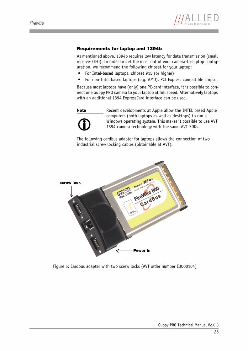
Because most laptops have (only) one PC-card interface, it is possible to con-nect one Guppy PRO camera to your laptop at full speed. Alternatively laptops with an additional 1394 ExpressCard interface can be used.
The following cardbus adapter for laptops allows the connection of two industrial screw locking cables (obtainable at AVT).
Note
Recent developments at Apple allow the INTEL based Apple computers (both laptops as well as desktops) to run a Windows operating system. This makes it possible to use AVT 1394 camera technology with the same AVT-SDKs.
Figure 5: Cardbus adapter with two screw locks (AVT order number E3000104)
FireWire
Guppy PRO Technical Manual V2.0.3
27
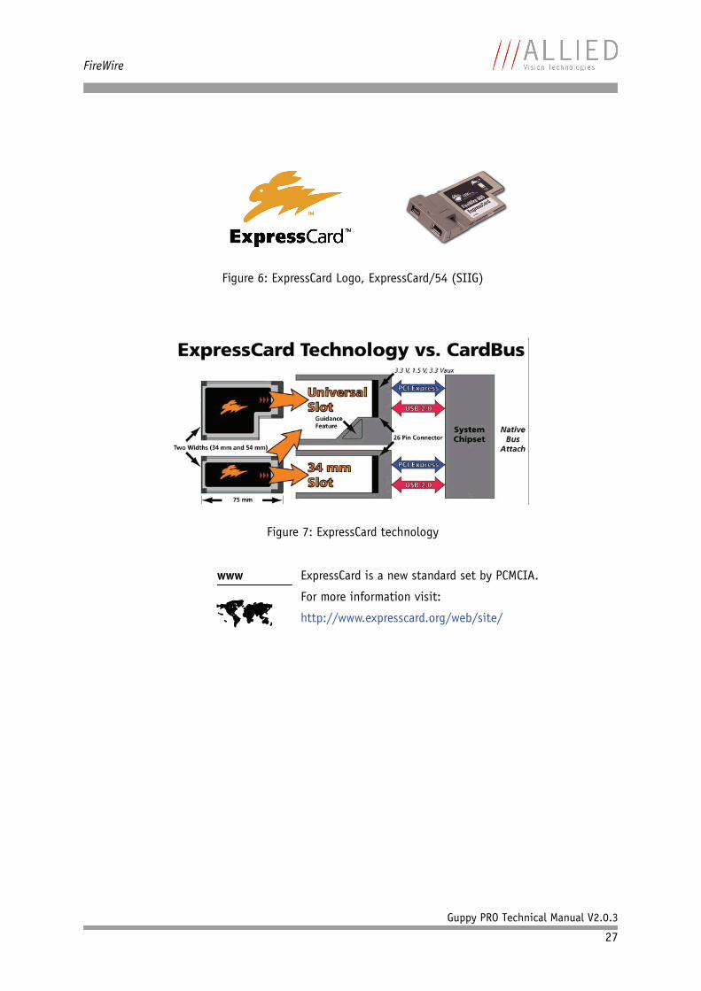
Figure 6: ExpressCard Logo, ExpressCard/54 (SIIG)
Figure 7: ExpressCard technology
www
ExpressCard is a new standard set by PCMCIA.
For more information visit:
http://www.expresscard.org/web/site/
FireWire
Guppy PRO Technical Manual V2.0.3
28
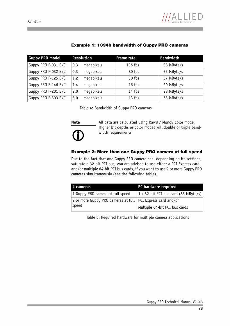
Example 1: 1394b bandwidth of Guppy PRO cameras
Example 2: More than one Guppy PRO camera at full speed
Due to the fact that one Guppy PRO camera can, depending on its settings, saturate a 32-bit PCI bus, you are advised to use either a PCI Express card and/or multiple 64-bit PCI bus cards, if you want to use 2 or more Guppy PRO cameras simultaneously (see the following table).
Guppy PRO model Resolution Frame rate Bandwidth
Guppy PRO F-031 B/C 0.3 megapixels 136 fps 38 MByte/s
Guppy PRO F-032 B/C 0.3 megapixels 80 fps 22 MByte/s
Guppy PRO F-125 B/C 1.2 megapixels 30 fps 37 MByte/s
Guppy PRO F-146 B/C 1.4 megapixels 16 fps 20 MByte/s
Guppy PRO F-201 B/C 2.0 megapixels 14 fps 28 MByte/s
Guppy PRO F-503 B/C 5.0 megapixels 13 fps 65 MByte/s
Table 4: Bandwidth of Guppy PRO cameras
Note
All data are calculated using Raw8 / Mono8 color mode. Higher bit depths or color modes will double or triple band-width requirements.
# cameras PC hardware required
1 Guppy PRO camera at full speed 1 x 32-bit PCI bus card (85 MByte/s)
2 or more Guppy PRO cameras at full speed
PCI Express card and/or
Multiple 64-bit PCI bus cards
Table 5: Required hardware for multiple camera applications
FireWire
Guppy PRO Technical Manual V2.0.3
29
FireWire Plug & play capabilitiesFireWire devices implement the ISO/IEC 13213 configuration ROM model for device configuration and identification, to provide plug & play capability. All FireWire devices are identified by an IEEE EUI-64 unique identifier (an exten-sion of the 48-bit Ethernet MAC address format) in addition to well-known codes indicating the type of device and protocols it supports. For further details read Chapter Configuration of the camera on page 182.
FireWire hot-plug and screw-lock precautions
Caution
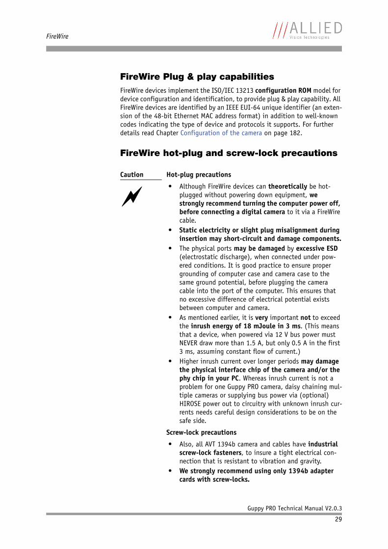
Hot-plug precautions
• Although FireWire devices can theoretically be hot-plugged without powering down equipment, we strongly recommend turning the computer power off, before connecting a digital camera to it via a FireWire cable.
• Static electricity or slight plug misalignment during insertion may short-circuit and damage components.
• The physical ports may be damaged by excessive ESD (electrostatic discharge), when connected under pow-ered conditions. It is good practice to ensure proper grounding of computer case and camera case to the same ground potential, before plugging the camera cable into the port of the computer. This ensures that no excessive difference of electrical potential exists between computer and camera.
• As mentioned earlier, it is very important not to exceed the inrush energy of 18 mJoule in 3 ms. (This means that a device, when powered via 12 V bus power must NEVER draw more than 1.5 A, but only 0.5 A in the first 3 ms, assuming constant flow of current.)
• Higher inrush current over longer periods may damage the physical interface chip of the camera and/or the phy chip in your PC. Whereas inrush current is not a problem for one Guppy PRO camera, daisy chaining mul-tiple cameras or supplying bus power via (optional) HIROSE power out to circuitry with unknown inrush cur-rents needs careful design considerations to be on the safe side.
Screw-lock precautions
• Also, all AVT 1394b camera and cables have industrial screw-lock fasteners, to insure a tight electrical con-nection that is resistant to vibration and gravity.
• We strongly recommend using only 1394b adapter cards with screw-locks.
FireWire
Guppy PRO Technical Manual V2.0.3
30
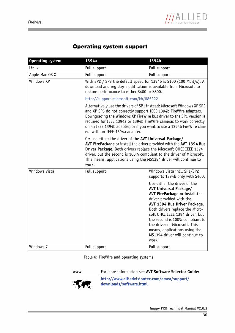
Operating system support
Operating system 1394a 1394b
Linux Full support Full support
Apple Mac OS X Full support Full support
Windows XP With SP2 / SP3 the default speed for 1394b is S100 (100 Mbit/s). A download and registry modification is available from Microsoft to restore performance to either S400 or S800.
http://support.microsoft.com/kb/885222
Alternatively use the drivers of SP1 instead: Microsoft Windows XP SP2 and XP SP3 do not correctly support IEEE 1394b FireWire adapters. Downgrading the Windows XP FireWire bus driver to the SP1 version is required for IEEE 1394a or 1394b FireWire cameras to work correctly on an IEEE 1394b adapter, or if you want to use a 1394b FireWire cam-era with an IEEE 1394a adapter.
Or: use either the driver of the AVT Universal Package/AVT FirePackage or install the driver provided with the AVT 1394 Bus Driver Package. Both drivers replace the Microsoft OHCI IEEE 1394 driver, but the second is 100% compliant to the driver of Microsoft. This means, applications using the MS1394 driver will continue to work.
Windows Vista Full support Windows Vista incl. SP1/SP2 supports 1394b only with S400.
Use either the driver of the AVT Universal Package/AVT FirePackage or install the driver provided with the AVT 1394 Bus Driver Package. Both drivers replace the Micro-soft OHCI IEEE 1394 driver, but the second is 100% compliant to the driver of Microsoft. This means, applications using the MS1394 driver will continue to work.
Windows 7 Full support Full support
Table 6: FireWire and operating systems
www
For more information see AVT Software Selector Guide:
http://www.alliedvisiontec.com/emea/support/downloads/software.html
Filter and lenses
Guppy PRO Technical Manual V2.0.3
31
Filter and lenses
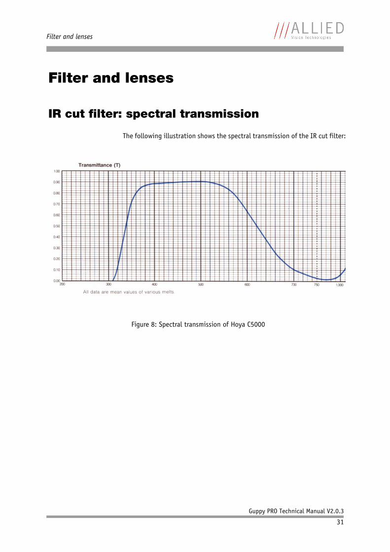
IR cut filter: spectral transmission
The following illustration shows the spectral transmission of the IR cut filter:
Figure 8: Spectral transmission of Hoya C5000
Filter and lenses
Guppy PRO Technical Manual V2.0.3
32
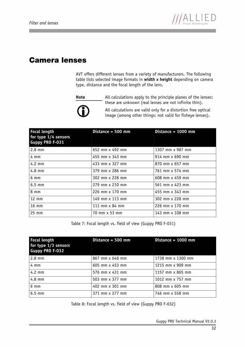
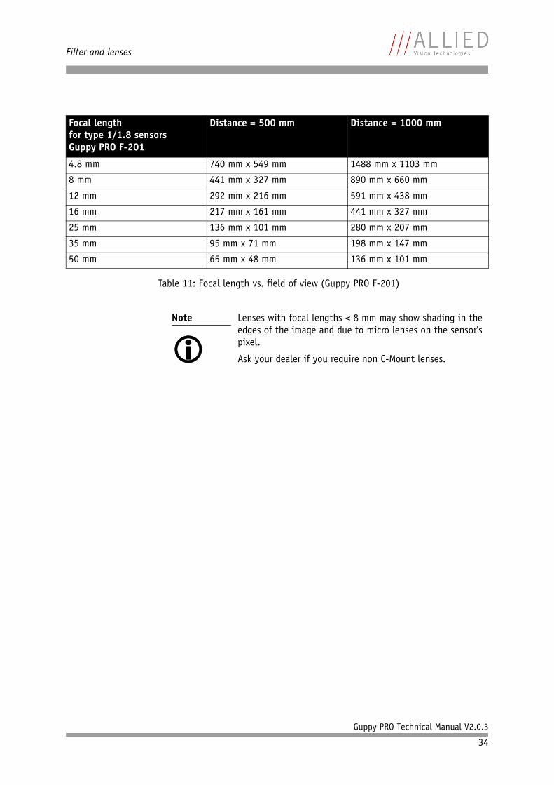
Camera lenses
AVT offers different lenses from a variety of manufacturers. The following table lists selected image formats in width x height depending on camera type, distance and the focal length of the lens.
Note
All calculations apply to the principle planes of the lenses: these are unknown (real lenses are not infinite thin).
All calculations are valid only for a distortion free optical image (among other things: not valid for fisheye lenses).
Focal lengthfor type 1/4 sensorsGuppy PRO F-031
Distance = 500 mm Distance = 1000 mm
2.8 mm 652 mm x 492 mm 1307 mm x 987 mm
4 mm 455 mm x 343 mm 914 mm x 690 mm
4.2 mm 433 mm x 327 mm 870 mm x 657 mm
4.8 mm 379 mm x 286 mm 761 mm x 574 mm
6 mm 302 mm x 228 mm 608 mm x 459 mm
6.5 mm 279 mm x 210 mm 561 mm x 423 mm
8 mm 226 mm x 170 mm 455 mm x 343 mm
12 mm 149 mm x 113 mm 302 mm x 228 mm
16 mm 111 mm x 84 mm 226 mm x 170 mm
25 mm 70 mm x 53 mm 143 mm x 108 mm
Table 7: Focal length vs. field of view (Guppy PRO F-031)
Focal lengthfor type 1/3 sensorsGuppy PRO F-032
Distance = 500 mm Distance = 1000 mm
2.8 mm 867 mm x 648 mm 1738 mm x 1300 mm
4 mm 605 mm x 453 mm 1215 mm x 909 mm
4.2 mm 576 mm x 431 mm 1157 mm x 865 mm
4.8 mm 503 mm x 377 mm 1012 mm x 757 mm
6 mm 402 mm x 301 mm 808 mm x 605 mm
6.5 mm 371 mm x 277 mm 746 mm x 558 mm
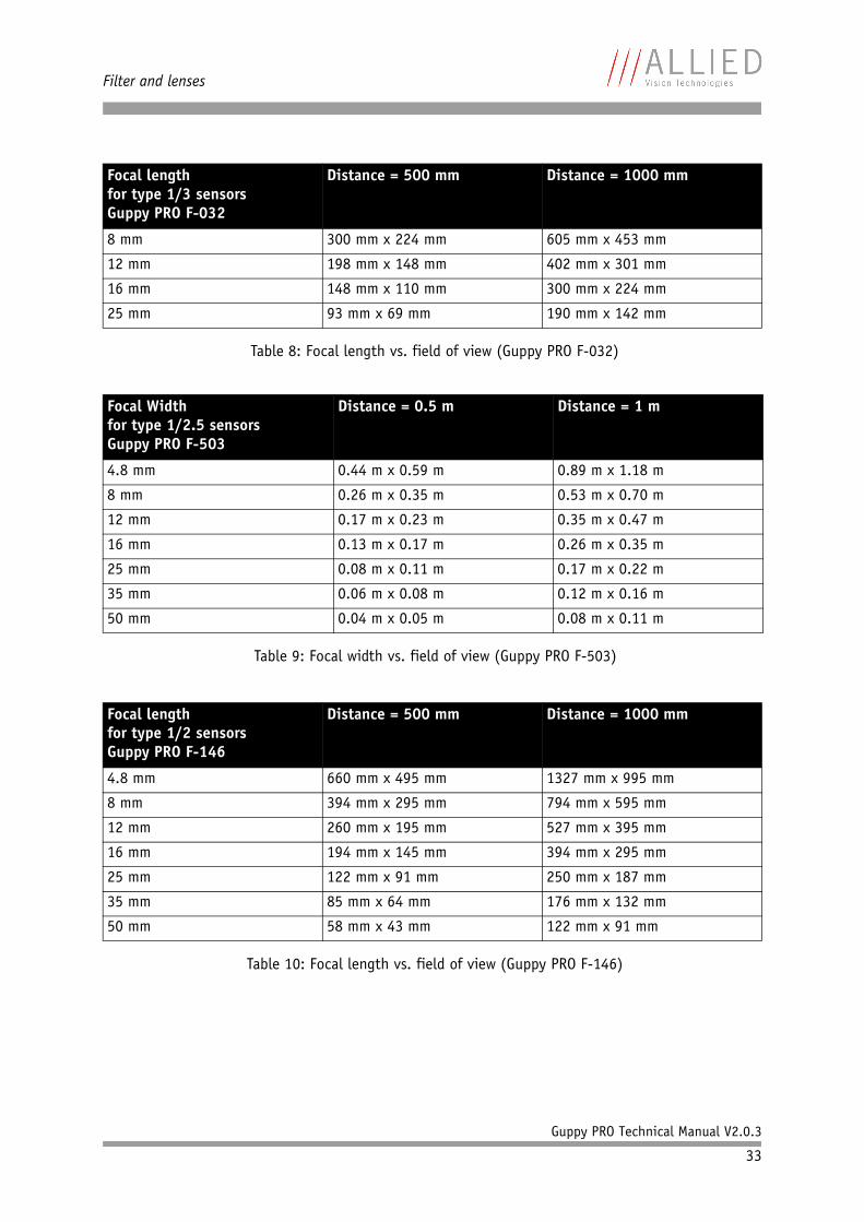
Table 8: Focal length vs. field of view (Guppy PRO F-032)
Filter and lenses
Guppy PRO Technical Manual V2.0.3
33
8 mm 300 mm x 224 mm 605 mm x 453 mm
12 mm 198 mm x 148 mm 402 mm x 301 mm
16 mm 148 mm x 110 mm 300 mm x 224 mm
25 mm 93 mm x 69 mm 190 mm x 142 mm
Focal Widthfor type 1/2.5 sensorsGuppy PRO F-503
Distance = 0.5 m Distance = 1 m
4.8 mm 0.44 m x 0.59 m 0.89 m x 1.18 m
8 mm 0.26 m x 0.35 m 0.53 m x 0.70 m
12 mm 0.17 m x 0.23 m 0.35 m x 0.47 m
16 mm 0.13 m x 0.17 m 0.26 m x 0.35 m
25 mm 0.08 m x 0.11 m 0.17 m x 0.22 m
35 mm 0.06 m x 0.08 m 0.12 m x 0.16 m
50 mm 0.04 m x 0.05 m 0.08 m x 0.11 m
Table 9: Focal width vs. field of view (Guppy PRO F-503)
Focal lengthfor type 1/2 sensorsGuppy PRO F-146
Distance = 500 mm Distance = 1000 mm
4.8 mm 660 mm x 495 mm 1327 mm x 995 mm
8 mm 394 mm x 295 mm 794 mm x 595 mm
12 mm 260 mm x 195 mm 527 mm x 395 mm
16 mm 194 mm x 145 mm 394 mm x 295 mm
25 mm 122 mm x 91 mm 250 mm x 187 mm
35 mm 85 mm x 64 mm 176 mm x 132 mm
50 mm 58 mm x 43 mm 122 mm x 91 mm
Table 10: Focal length vs. field of view (Guppy PRO F-146)
Focal lengthfor type 1/3 sensorsGuppy PRO F-032
Distance = 500 mm Distance = 1000 mm
Table 8: Focal length vs. field of view (Guppy PRO F-032)
Filter and lenses
Guppy PRO Technical Manual V2.0.3
34
Focal lengthfor type 1/1.8 sensorsGuppy PRO F-201
Distance = 500 mm Distance = 1000 mm
4.8 mm 740 mm x 549 mm 1488 mm x 1103 mm
8 mm 441 mm x 327 mm 890 mm x 660 mm
12 mm 292 mm x 216 mm 591 mm x 438 mm
16 mm 217 mm x 161 mm 441 mm x 327 mm
25 mm 136 mm x 101 mm 280 mm x 207 mm
35 mm 95 mm x 71 mm 198 mm x 147 mm
50 mm 65 mm x 48 mm 136 mm x 101 mm
Table 11: Focal length vs. field of view (Guppy PRO F-201)
Note
Lenses with focal lengths < 8 mm may show shading in the edges of the image and due to micro lenses on the sensor's pixel.
Ask your dealer if you require non C-Mount lenses.
Specifications
Guppy PRO Technical Manual V2.0.3
35
Specifications
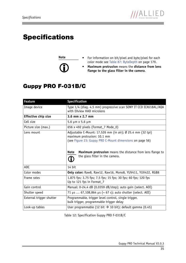
Guppy PRO F-031B/C
Note
• For information on bit/pixel and byte/pixel for each
color mode see Table 87: ByteDepth on page 179.• Maximum protrusion means the distance from lens
flange to the glass filter in the camera.
Feature Specification
Image device Type 1/4 (diag. 4.5 mm) progressive scan SONY IT CCD ICX618AL/AQA with EXview HAD microlens
Effective chip size 3.6 mm x 2.7 mm
Cell size 5.6 µm x 5.6 µm
Picture size (max.) 656 x 492 pixels (Format_7 Mode_0)
Lens mount Adjustable C-Mount: 17.526 mm (in air); Ø 25.4 mm (32 tpi)maximum protrusion: 10.1 mm(see Figure 23: Guppy PRO C-Mount dimensions on page 56)
ADC 14 bit
Color modes Only color: Raw8, Raw12, Raw16, Mono8, YUV411, YUV422, RGB8
Frame rates 1.875 fps; 3.75 fps; 7.5 fps; 15 fps; 30 fps; 60 fps; 120 fps Up to 121 fps in Format_7
Gain control Manual: 0-24.4 dB (0.0359 dB/step); auto gain (select. AOI)
Shutter speed 71 µs … 67,108,864 µs (~ 67 s); auto shutter (select. AOI)
External trigger shutter Programmable, trigger level control, single trigger,bulk trigger, programmable trigger delay
Look-up tables User programmable (12 bit 10 bit); default gamma (0.45)
Table 12: Specification Guppy PRO F-031B/C
Note
Maximum protrusion means the distance from lens flange to the glass filter in the camera.
Specifications
Guppy PRO Technical Manual V2.0.3
36
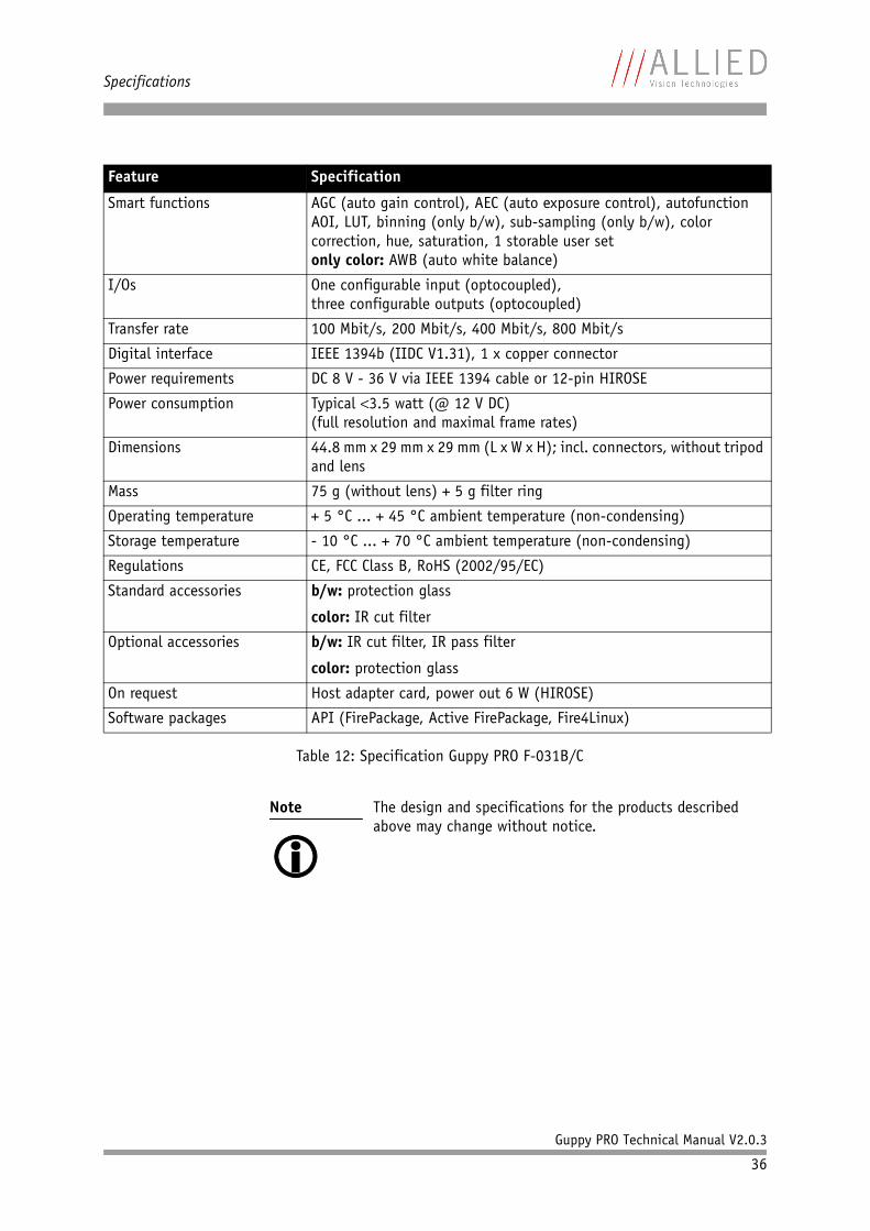
Smart functions AGC (auto gain control), AEC (auto exposure control), autofunction AOI, LUT, binning (only b/w), sub-sampling (only b/w), color correction, hue, saturation, 1 storable user setonly color: AWB (auto white balance)
I/Os One configurable input (optocoupled),three configurable outputs (optocoupled)
Transfer rate 100 Mbit/s, 200 Mbit/s, 400 Mbit/s, 800 Mbit/s
Digital interface IEEE 1394b (IIDC V1.31), 1 x copper connector
Power requirements DC 8 V - 36 V via IEEE 1394 cable or 12-pin HIROSE
Power consumption Typical 3.5 watt (@ 12 V DC)(full resolution and maximal frame rates)
Dimensions 44.8 mm x 29 mm x 29 mm (L x W x H); incl. connectors, without tripod and lens
Mass 75 g (without lens) + 5 g filter ring
Operating temperature + 5 °C ... + 45 °C ambient temperature (non-condensing)
Storage temperature - 10 °C ... + 70 °C ambient temperature (non-condensing)
Regulations CE, FCC Class B, RoHS (2002/95/EC)
Standard accessories b/w: protection glass
color: IR cut filter
Optional accessories b/w: IR cut filter, IR pass filter
color: protection glass
On request Host adapter card, power out 6 W (HIROSE)
Software packages API (FirePackage, Active FirePackage, Fire4Linux)
Note
The design and specifications for the products described above may change without notice.
Feature Specification
Table 12: Specification Guppy PRO F-031B/C

Specifications
Guppy PRO Technical Manual V2.0.3
37
Guppy PRO F-032B/C
Feature Specification
Image device Type 1/3 (diag. 6 mm) progressive scan SONY IT CCD ICX424AL/AQ with HAD microlens
Effective chip size 4.9 mm x 3.7 mm
Cell size 7.4 µm x 7.4 µm
Picture size (max.) 656 x 492 pixels (Format_7 Mode_0)
Lens mount Adjustable C-Mount: 17.526 mm (in air); Ø 25.4 mm (32 tpi)maximum protrusion: 10.1 mm(see Figure 23: Guppy PRO C-Mount dimensions on page 56)
ADC 12 bit
Color modes Only color: Raw8, Raw12, Raw16, Mono8, YUV411, YUV422, RGB8
Frame rates 1.875 fps; 3.75 fps; 7.5 fps; 15 fps; 30 fps; 60 fpsUp to 79 fps in Format_7
Gain control Manual: 0-24.4 dB (0.0359 dB/step); auto gain (select. AOI)
Shutter speed 27 µs … 67,108,864 µs (~ 67 s); auto shutter (select. AOI)
External trigger shutter Programmable, trigger level control, single trigger,bulk trigger, programmable trigger delay
Look-up tables User programmable (12 bit 10 bit); default gamma (0.45)
Smart functions AGC (auto gain control), AEC (auto exposure control), autofunction AOI, LUT, binning (only b/w), sub-sampling (only b/w), color correction, hue, saturation, 1 storable user setonly color: AWB (auto white balance)
I/Os One configurable input (optocoupled),three configurable outputs (optocoupled)
Transfer rate 100 Mbit/s, 200 Mbit/s, 400 Mbit/s, 800 Mbit/s
Digital interface IEEE 1394b (IIDC V1.31), 1 x copper connector
Power requirements DC 8 V - 36 V via IEEE 1394 cable or 12-pin HIROSE
Power consumption Typical 3.5 watt (@ 12 V DC)
(full resolution and maximal frame rates)
Dimensions 44.8 mm x 29 mm x 29 mm (L x W x H); incl. connectors, without tripod and lens
Table 13: Specification Guppy PRO F-032B/C
Note
Maximum protrusion means the distance from lens flange to the glass filter in the camera.

Specifications
Guppy PRO Technical Manual V2.0.3
38
Mass 75 g (without lens) + 5 g filter ring
Operating temperature + 5 °C ... + 45 °C ambient temperature (non-condensing)
Storage temperature - 10 °C ... + 70 °C ambient temperature (non-condensing)
Regulations CE, FCC Class B, RoHS (2002/95/EC)
Standard accessories b/w: protection glass
color: IR cut filter
Optional accessories b/w: IR cut filter, IR pass filter
color: protection glass
On request Host adapter card, power out 6 W (HIROSE)
Software packages API (FirePackage, Active FirePackage, Fire4Linux)
Note
The design and specifications for the products described above may change without notice.
Feature Specification
Table 13: Specification Guppy PRO F-032B/C
Specifications
Guppy PRO Technical Manual V2.0.3
39
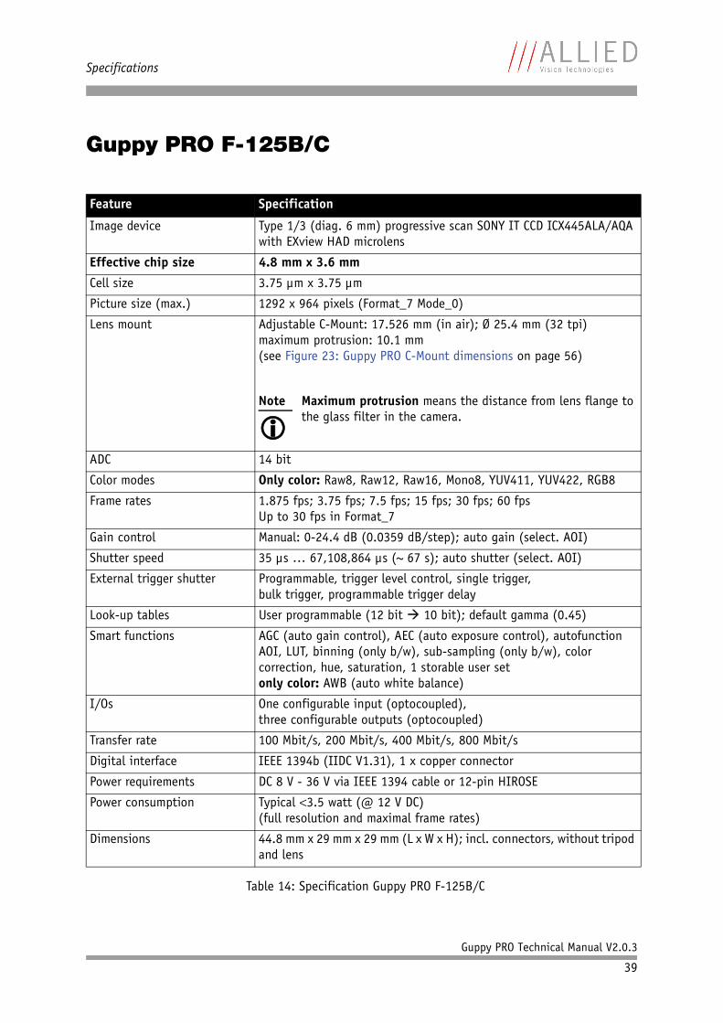
Guppy PRO F-125B/C
Feature Specification
Image device Type 1/3 (diag. 6 mm) progressive scan SONY IT CCD ICX445ALA/AQA with EXview HAD microlens
Effective chip size 4.8 mm x 3.6 mm
Cell size 3.75 µm x 3.75 µm
Picture size (max.) 1292 x 964 pixels (Format_7 Mode_0)
Lens mount Adjustable C-Mount: 17.526 mm (in air); Ø 25.4 mm (32 tpi)maximum protrusion: 10.1 mm(see Figure 23: Guppy PRO C-Mount dimensions on page 56)
ADC 14 bit
Color modes Only color: Raw8, Raw12, Raw16, Mono8, YUV411, YUV422, RGB8
Frame rates 1.875 fps; 3.75 fps; 7.5 fps; 15 fps; 30 fps; 60 fpsUp to 30 fps in Format_7
Gain control Manual: 0-24.4 dB (0.0359 dB/step); auto gain (select. AOI)
Shutter speed 35 µs … 67,108,864 µs (~ 67 s); auto shutter (select. AOI)
External trigger shutter Programmable, trigger level control, single trigger,bulk trigger, programmable trigger delay
Look-up tables User programmable (12 bit 10 bit); default gamma (0.45)
Smart functions AGC (auto gain control), AEC (auto exposure control), autofunction AOI, LUT, binning (only b/w), sub-sampling (only b/w), color correction, hue, saturation, 1 storable user setonly color: AWB (auto white balance)
I/Os One configurable input (optocoupled),three configurable outputs (optocoupled)
Transfer rate 100 Mbit/s, 200 Mbit/s, 400 Mbit/s, 800 Mbit/s
Digital interface IEEE 1394b (IIDC V1.31), 1 x copper connector
Power requirements DC 8 V - 36 V via IEEE 1394 cable or 12-pin HIROSE
Power consumption Typical 3.5 watt (@ 12 V DC)(full resolution and maximal frame rates)
Dimensions 44.8 mm x 29 mm x 29 mm (L x W x H); incl. connectors, without tripod and lens
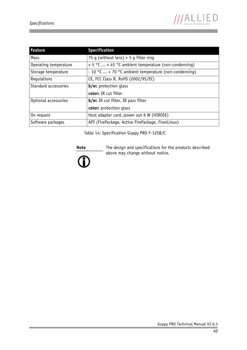
Table 14: Specification Guppy PRO F-125B/C
Note
Maximum protrusion means the distance from lens flange to the glass filter in the camera.
Specifications
Guppy PRO Technical Manual V2.0.3
40
Mass 75 g (without lens) + 5 g filter ring
Operating temperature + 5 °C ... + 45 °C ambient temperature (non-condensing)
Storage temperature - 10 °C ... + 70 °C ambient temperature (non-condensing)
Regulations CE, FCC Class B, RoHS (2002/95/EC)
Standard accessories b/w: protection glass
color: IR cut filter
Optional accessories b/w: IR cut filter, IR pass filter
color: protection glass
On request Host adapter card, power out 6 W (HIROSE)
Software packages API (FirePackage, Active FirePackage, Fire4Linux)
Note
The design and specifications for the products described above may change without notice.
Feature Specification
Table 14: Specification Guppy PRO F-125B/C
Specifications
Guppy PRO Technical Manual V2.0.3
41
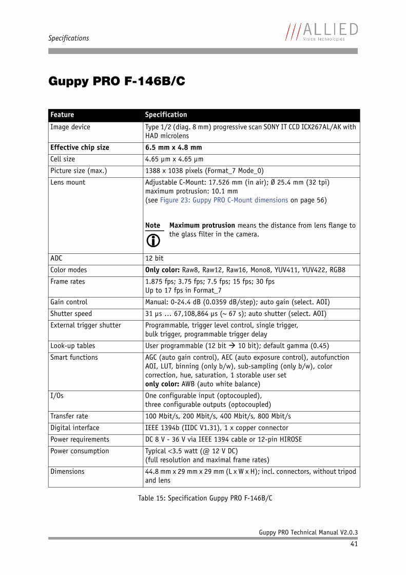
Guppy PRO F-146B/C
Feature Specification
Image device Type 1/2 (diag. 8 mm) progressive scan SONY IT CCD ICX267AL/AK with HAD microlens
Effective chip size 6.5 mm x 4.8 mm
Cell size 4.65 µm x 4.65 µm
Picture size (max.) 1388 x 1038 pixels (Format_7 Mode_0)
Lens mount Adjustable C-Mount: 17.526 mm (in air); Ø 25.4 mm (32 tpi)maximum protrusion: 10.1 mm(see Figure 23: Guppy PRO C-Mount dimensions on page 56)
ADC 12 bit
Color modes Only color: Raw8, Raw12, Raw16, Mono8, YUV411, YUV422, RGB8
Frame rates 1.875 fps; 3.75 fps; 7.5 fps; 15 fps; 30 fpsUp to 17 fps in Format_7
Gain control Manual: 0-24.4 dB (0.0359 dB/step); auto gain (select. AOI)
Shutter speed 31 µs … 67,108,864 µs (~ 67 s); auto shutter (select. AOI)
External trigger shutter Programmable, trigger level control, single trigger,bulk trigger, programmable trigger delay
Look-up tables User programmable (12 bit 10 bit); default gamma (0.45)
Smart functions AGC (auto gain control), AEC (auto exposure control), autofunction AOI, LUT, binning (only b/w), sub-sampling (only b/w), color correction, hue, saturation, 1 storable user setonly color: AWB (auto white balance)
I/Os One configurable input (optocoupled),three configurable outputs (optocoupled)
Transfer rate 100 Mbit/s, 200 Mbit/s, 400 Mbit/s, 800 Mbit/s
Digital interface IEEE 1394b (IIDC V1.31), 1 x copper connector
Power requirements DC 8 V - 36 V via IEEE 1394 cable or 12-pin HIROSE
Power consumption Typical 3.5 watt (@ 12 V DC)(full resolution and maximal frame rates)
Dimensions 44.8 mm x 29 mm x 29 mm (L x W x H); incl. connectors, without tripod and lens
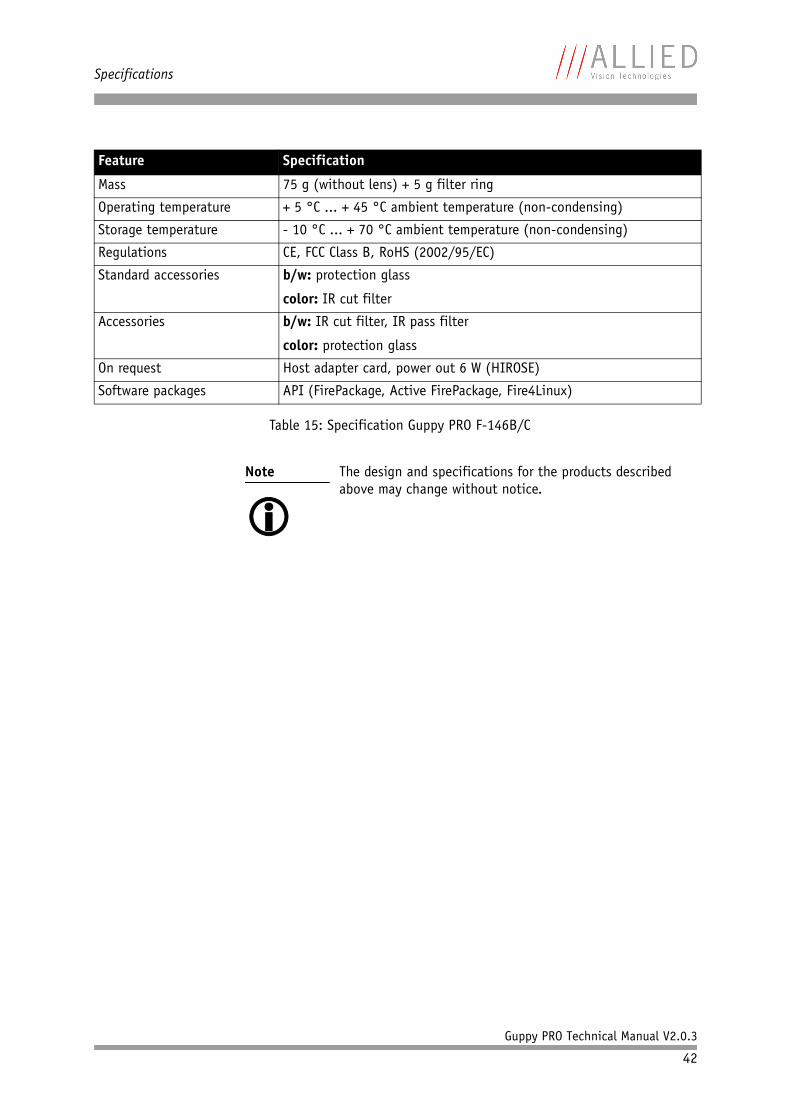
Table 15: Specification Guppy PRO F-146B/C
Note
Maximum protrusion means the distance from lens flange to the glass filter in the camera.
Specifications
Guppy PRO Technical Manual V2.0.3
42
Mass 75 g (without lens) + 5 g filter ring
Operating temperature + 5 °C ... + 45 °C ambient temperature (non-condensing)
Storage temperature - 10 °C ... + 70 °C ambient temperature (non-condensing)
Regulations CE, FCC Class B, RoHS (2002/95/EC)
Standard accessories b/w: protection glass
color: IR cut filter
Accessories b/w: IR cut filter, IR pass filter
color: protection glass
On request Host adapter card, power out 6 W (HIROSE)
Software packages API (FirePackage, Active FirePackage, Fire4Linux)
Note
The design and specifications for the products described above may change without notice.
Feature Specification
Table 15: Specification Guppy PRO F-146B/C

Specifications
Guppy PRO Technical Manual V2.0.3
43
Guppy PRO F-201B/C
Feature Specification
Image device Type 1/1.8 (diag. 8.9 mm) progressive scan SONY IT CCD ICX274AL/AQ with Super HAD microlens
Effective chip size 7.1 mm x 5.4 mm
Cell size 4.40 µm x 4.40 µm
Picture size (max.) 1624 x 1234 pixels (Format_7 Mode_0)
Lens mount Adjustable C-Mount: 17.526 mm (in air); Ø 25.4 mm (32 tpi)maximum protrusion: 10.1 mm(see Figure 23: Guppy PRO C-Mount dimensions on page 56)
ADC 12 bit
Color modes Only color: Raw8, Raw12, Raw16, Mono8, YUV411, YUV422, RGB8
Frame rates 1.875 fps; 3.75 fps; 7.5 fps; 30 fpsUp to 14 fps in Format_7
Gain control Manual: 0-24.4 dB (0.0359 dB/step); auto gain (select. AOI)
Shutter speed 45 µs … 67,108,864 µs (~ 67 s); auto shutter (select. AOI)
External trigger shutter Programmable, trigger level control, single trigger,bulk trigger, programmable trigger delay
Look-up tables User programmable (12 bit 10 bit); default gamma (0.45)
Smart functions AGC (auto gain control), AEC (auto exposure control), autofunction AOI, LUT, binning (only b/w), sub-sampling (only b/w), color correction, hue, saturation, 1 storable user setonly color: AWB (auto white balance)
I/Os One configurable input (optocoupled),three configurable outputs (optocoupled)
Transfer rate 100 Mbit/s, 200 Mbit/s, 400 Mbit/s, 800 Mbit/s
Digital interface IEEE 1394b (IIDC V1.31), 1 x copper connector
Power requirements DC 8 V - 36 V via IEEE 1394 cable or 12-pin HIROSE
Power consumption Typical 3.5 watt (@ 12 V DC)(full resolution and maximal frame rates)
Dimensions 44.8 mm x 29 mm x 29 mm (L x W x H); incl. connectors, without tripod and lens
Table 16: Specification Guppy PRO F-201B/C
Note
Maximum protrusion means the distance from lens flange to the glass filter in the camera.

Specifications
Guppy PRO Technical Manual V2.0.3
44
Mass 75 g (without lens) + 5 g filter ring
Operating temperature + 5 °C ... + 45 °C ambient temperature (non-condensing)
Storage temperature - 10 °C ... + 70 °C ambient temperature (non-condensing)
Regulations CE, FCC Class B, RoHS (2002/95/EC)
Standard accessories b/w: protection glass
color: IR cut filter
Optional accessories b/w: IR cut filter, IR pass filter
color: protection glass
On request Host adapter card, power out 6 W (HIROSE)
Software packages API (FirePackage, Active FirePackage, Fire4Linux)
Note
The design and specifications for the products described above may change without notice.
Feature Specification
Table 16: Specification Guppy PRO F-201B/C
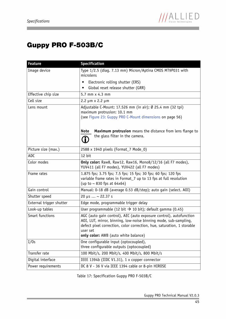
Specifications
Guppy PRO Technical Manual V2.0.3
45
Guppy PRO F-503B/C
Feature Specification
Image device Type 1/2.5 (diag. 7.13 mm) Micron/Aptina CMOS MT9P031 with microlens
• Electronic rolling shutter (ERS)• Global reset release shutter (GRR)
Effective chip size 5.7 mm x 4.3 mm
Cell size 2.2 µm x 2.2 µm
Lens mount Adjustable C-Mount: 17.526 mm (in air); Ø 25.4 mm (32 tpi)maximum protrusion: 10.1 mm(see Figure 23: Guppy PRO C-Mount dimensions on page 56)
Picture size (max.) 2588 x 1940 pixels (Format_7 Mode_0)
ADC 12 bit
Color modes Only color: Raw8, Raw12, Raw16, Mono8/12/16 (all F7 modes), YUV411 (all F7 modes), YUV422 (all F7 modes)
Frame rates 1.875 fps; 3.75 fps; 7.5 fps; 15 fps; 30 fps; 60 fps; 120 fpsvariable frame rates in Format_7 up to 13 fps at full resolution(up to ~ 830 fps at 64x64)
Gain control Manual: 0-18 dB (average 0.53 dB/step); auto gain (select. AOI)
Shutter speed 20 µs … ~ 22.37 s
External trigger shutter Edge mode, programmable trigger delay
Look-up tables User programmable (12 bit 10 bit); default gamma (0.45)
Smart functions AGC (auto gain control), AEC (auto exposure control), autofunction AOI, LUT, mirror, binning, low-noise binning mode, sub-sampling, defect pixel correction, color correction, hue, saturation, 1 storable user setonly color: AWB (auto white balance)
I/Os One configurable input (optocoupled),three configurable outputs (optocoupled)
Transfer rate 100 Mbit/s, 200 Mbit/s, 400 Mbit/s, 800 Mbit/s
Digital interface IEEE 1394b (IIDC V1.31), 1 x copper connector
Power requirements DC 8 V - 36 V via IEEE 1394 cable or 8-pin HIROSE
Table 17: Specification Guppy PRO F-503B/C
Note
Maximum protrusion means the distance from lens flange to the glass filter in the camera.
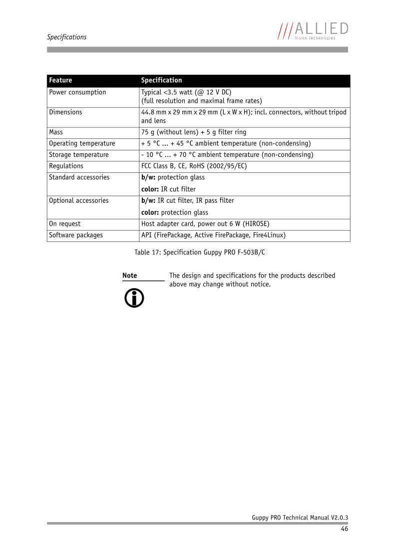
Specifications
Guppy PRO Technical Manual V2.0.3
46
Power consumption Typical 3.5 watt (@ 12 V DC)(full resolution and maximal frame rates)
Dimensions 44.8 mm x 29 mm x 29 mm (L x W x H); incl. connectors, without tripod and lens
Mass 75 g (without lens) + 5 g filter ring
Operating temperature + 5 °C ... + 45 °C ambient temperature (non-condensing)
Storage temperature - 10 °C ... + 70 °C ambient temperature (non-condensing)
Regulations FCC Class B, CE, RoHS (2002/95/EC)
Standard accessories b/w: protection glass
color: IR cut filter
Optional accessories b/w: IR cut filter, IR pass filter
color: protection glass
On request Host adapter card, power out 6 W (HIROSE)
Software packages API (FirePackage, Active FirePackage, Fire4Linux)
Note
The design and specifications for the products described above may change without notice.
Feature Specification
Table 17: Specification Guppy PRO F-503B/C
Specifications
Guppy PRO Technical Manual V2.0.3
47
Spectral sensitivity
Note
All measurements were done without protection glass / without filter.
The uncertainty in measurement of the QE values is 10%.(QE = Quantum Efficiency)
This is due to:
• Manufacturing tolerance of the sensor• Uncertainties in the measuring apparatus itself
(Ulbricht-Kugel/Ulbricht sphere, optometer, etc.)
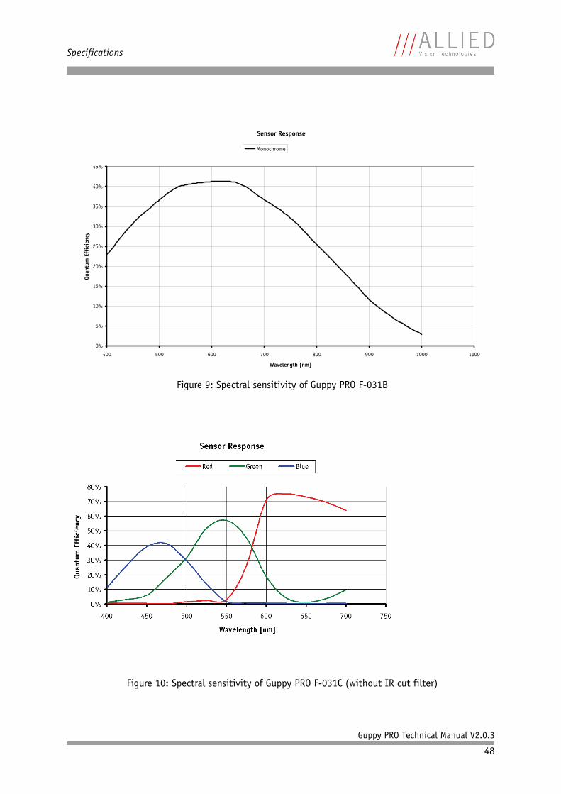
Specifications
Guppy PRO Technical Manual V2.0.3
48
Figure 9: Spectral sensitivity of Guppy PRO F-031B
Figure 10: Spectral sensitivity of Guppy PRO F-031C (without IR cut filter)
Sensor Response
0%
5%
10%
15%
20%
25%
30%
35%
40%
45%
400 500 600 700 800 900 1000 1100
Wavelength [nm]
Quan
tum
Eff
icie
ncy
Monochrome
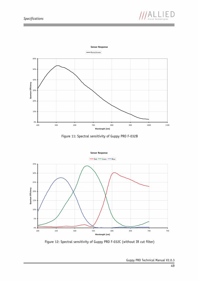
Specifications
Guppy PRO Technical Manual V2.0.3
49
Figure 11: Spectral sensitivity of Guppy PRO F-032B
Figure 12: Spectral sensitivity of Guppy PRO F-032C (without IR cut filter)
Sensor Response
0%
10%
20%
30%
40%
50%
60%
400 500 600 700 800 900 1000 1100
Wavelength [nm]
Quan
tum
Eff
icie
ncy
Monochrome
Sensor Response
0%
5%
10%
15%
20%
25%
30%
35%
400 450 500 550 600 650 700 750
Wavelength [nm]
Quan
tum
Eff
icie
ncy
Red Green Blue
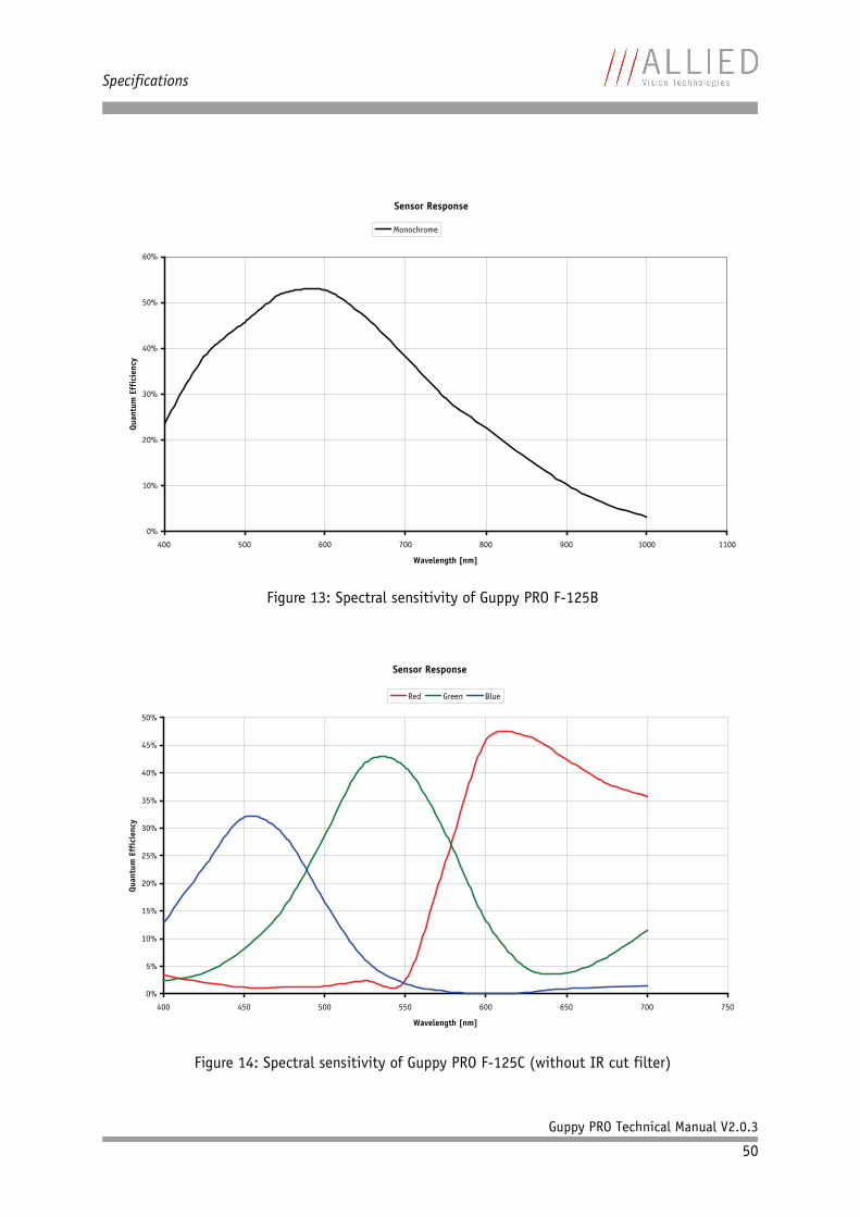
Specifications
Guppy PRO Technical Manual V2.0.3
50
Figure 13: Spectral sensitivity of Guppy PRO F-125B
Figure 14: Spectral sensitivity of Guppy PRO F-125C (without IR cut filter)
Sensor Response
0%
10%
20%
30%
40%
50%
60%
400 500 600 700 800 900 1000 1100
Wavelength [nm]
Quan
tum
Eff
icie
ncy
Monochrome
Sensor Response
0%
5%
10%
15%
20%
25%
30%
35%
40%
45%
50%
400 450 500 550 600 650 700 750
Wavelength [nm]
Quan
tum
Eff
icie
ncy
Red Green Blue
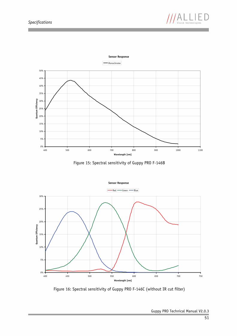
Specifications
Guppy PRO Technical Manual V2.0.3
51
Figure 15: Spectral sensitivity of Guppy PRO F-146B
Figure 16: Spectral sensitivity of Guppy PRO F-146C (without IR cut filter)
Sensor Response
0%
5%
10%
15%
20%
25%
30%
35%
40%
45%
50%
400 500 600 700 800 900 1000 1100
Wavelength [nm]
Quan
tum
Eff
icie
ncy
Monochrome
Sensor Response
0%
5%
10%
15%
20%
25%
30%
400 450 500 550 600 650 700 750
Wavelength [nm]
Quan
tum
Eff
icie
ncy
Red Green Blue
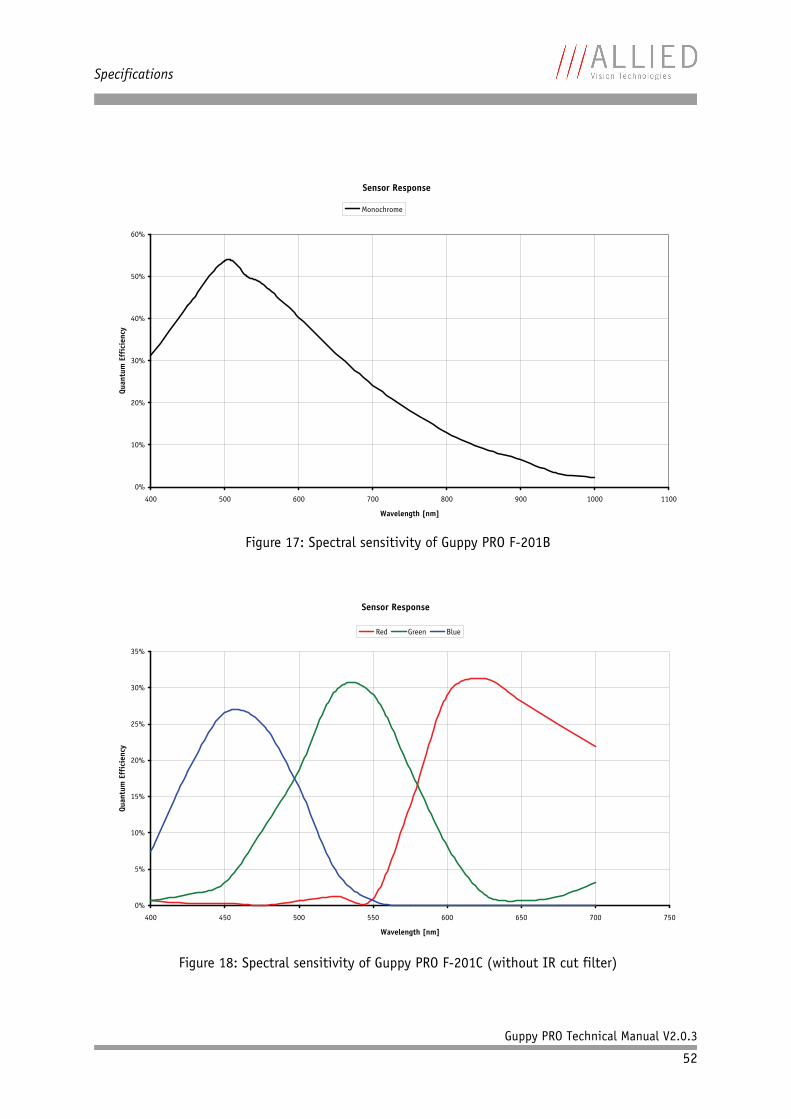
Specifications
Guppy PRO Technical Manual V2.0.3
52
Figure 17: Spectral sensitivity of Guppy PRO F-201B
Figure 18: Spectral sensitivity of Guppy PRO F-201C (without IR cut filter)
Sensor Response
0%
10%
20%
30%
40%
50%
60%
400 500 600 700 800 900 1000 1100
Wavelength [nm]
Quan
tum
Eff
icie
ncy
Monochrome
Sensor Response
0%
5%
10%
15%
20%
25%
30%
35%
400 450 500 550 600 650 700 750
Wavelength [nm]
Quan
tum
Eff
icie
ncy
Red Green Blue
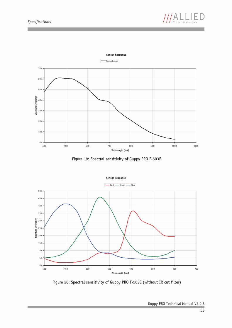
Specifications
Guppy PRO Technical Manual V2.0.3
53
Figure 19: Spectral sensitivity of Guppy PRO F-503B
Figure 20: Spectral sensitivity of Guppy PRO F-503C (without IR cut filter)
Sensor Response
0%
10%
20%
30%
40%
50%
60%
70%
400 500 600 700 800 900 1000 1100
Wavelength [nm]
Quan
tum
Eff
icie
ncy
Monochrome
Sensor Response
0%
5%
10%
15%
20%
25%
30%
35%
40%
45%
50%
400 450 500 550 600 650 700 750
Wavelength [nm]
Quan
tum
Eff
icie
ncy
Red Green Blue
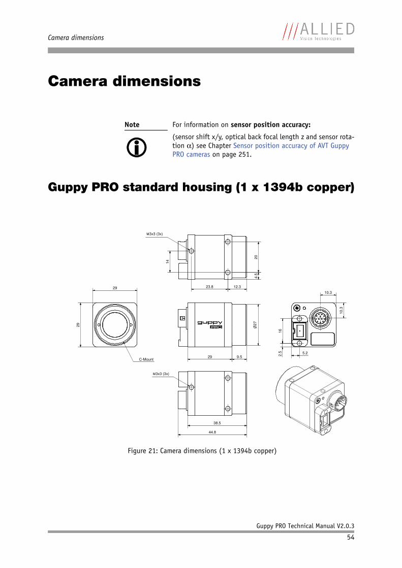
Camera dimensions
Guppy PRO Technical Manual V2.0.3
54
Camera dimensions
Guppy PRO standard housing (1 x 1394b copper)
Note
For information on sensor position accuracy:
(sensor shift x/y, optical back focal length z and sensor rota-tion ) see Chapter Sensor position accuracy of AVT Guppy PRO cameras on page 251.
Figure 21: Camera dimensions (1 x 1394b copper)
29
C-Mount
29
29 9.5
�27
10.3
10.3
5.22.5
16
38.5
44.8
�3x3 (3x)
�3x3 (3x)
14
23.8 12.3
204.
5
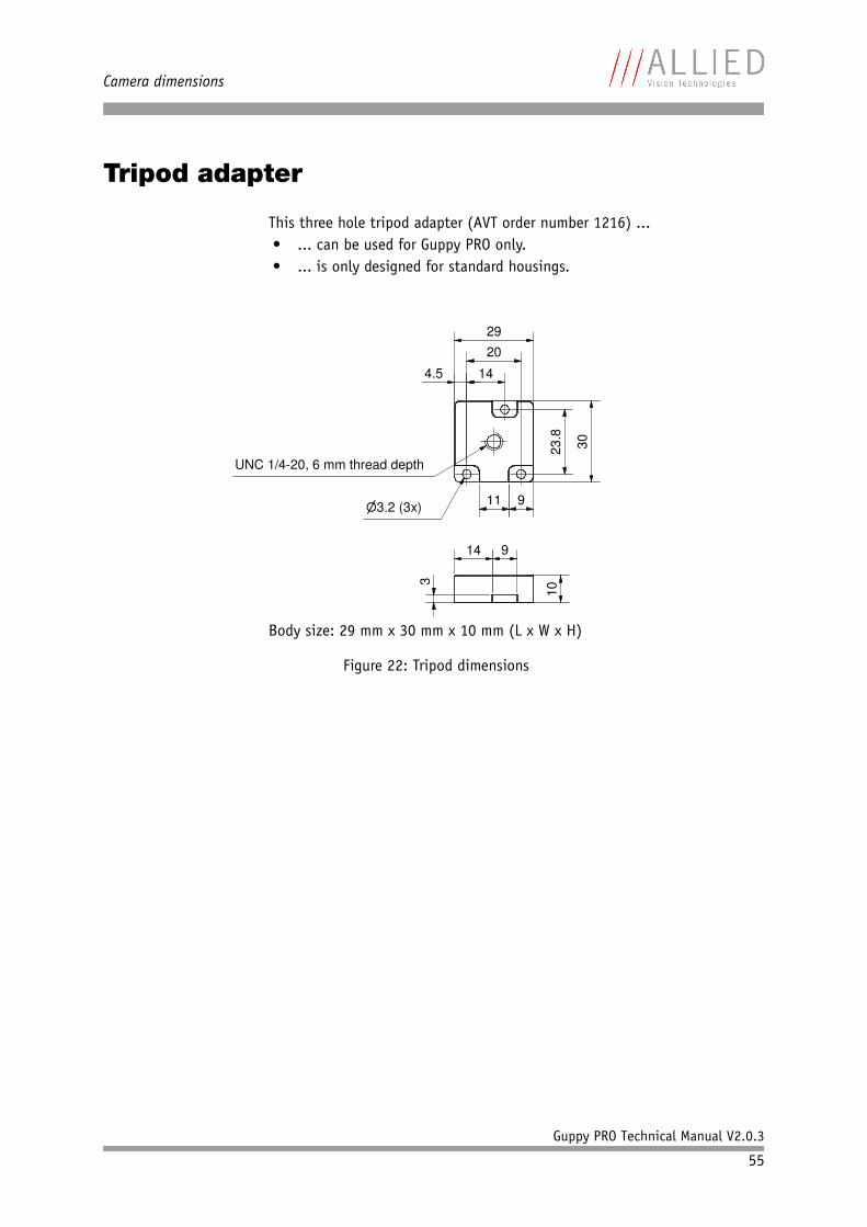
Camera dimensions
Guppy PRO Technical Manual V2.0.3
55
Tripod adapter
This three hole tripod adapter (AVT order number 1216) ...• ... can be used for Guppy PRO only.• ... is only designed for standard housings.
Body size: 29 mm x 30 mm x 10 mm (L x W x H)
Figure 22: Tripod dimensions
29
20
14
23.8
30
�3.2 (3x)
10
3
14 9
UNC 1/4-20, 6 mm thread depth
4.5
11 9
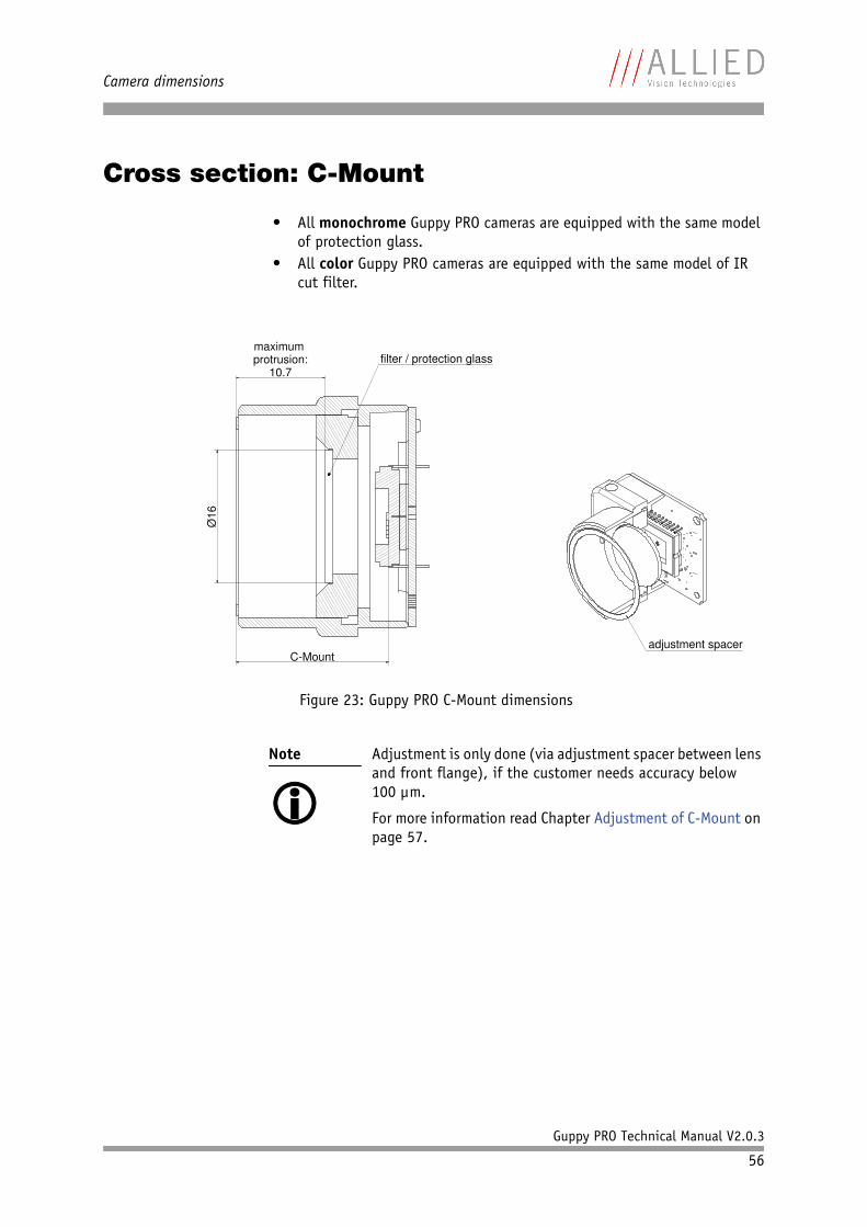
Camera dimensions
Guppy PRO Technical Manual V2.0.3
56
Cross section: C-Mount
• All monochrome Guppy PRO cameras are equipped with the same model of protection glass.
• All color Guppy PRO cameras are equipped with the same model of IR cut filter.
Figure 23: Guppy PRO C-Mount dimensions
Note
Adjustment is only done (via adjustment spacer between lens and front flange), if the customer needs accuracy below 100 µm.
For more information read Chapter Adjustment of C-Mount on page 57.
�
C-Mount
maximum protrusion:
10.7
Ø16
filter / protection glass
adjustment spacer
Camera dimensions
Guppy PRO Technical Manual V2.0.3
57
Adjustment of C-Mount
The dimensional adjustment cannot be done any more by the customer. All adjustments have to be done by the AVT factory.
Adjustment is only done (via adjustment spacer between lens and front flange), if the customer needs accuracy below 100 µm.
If you need any adjustments, please contact Customer Care: For phone numbers and e-mail: See Chapter Contacting Allied Vision Technologies on page 9.
Note
For all customers who know the C-Mount adjustment proce-dure from Pike and Oscar cameras:
The front flange of Guppy PRO cameras is a fixed part of the camera (and cannot be screwed).
As mentioned above: adjustment of C-Mount with Guppy PRO cameras can only be done by the AVT factory.
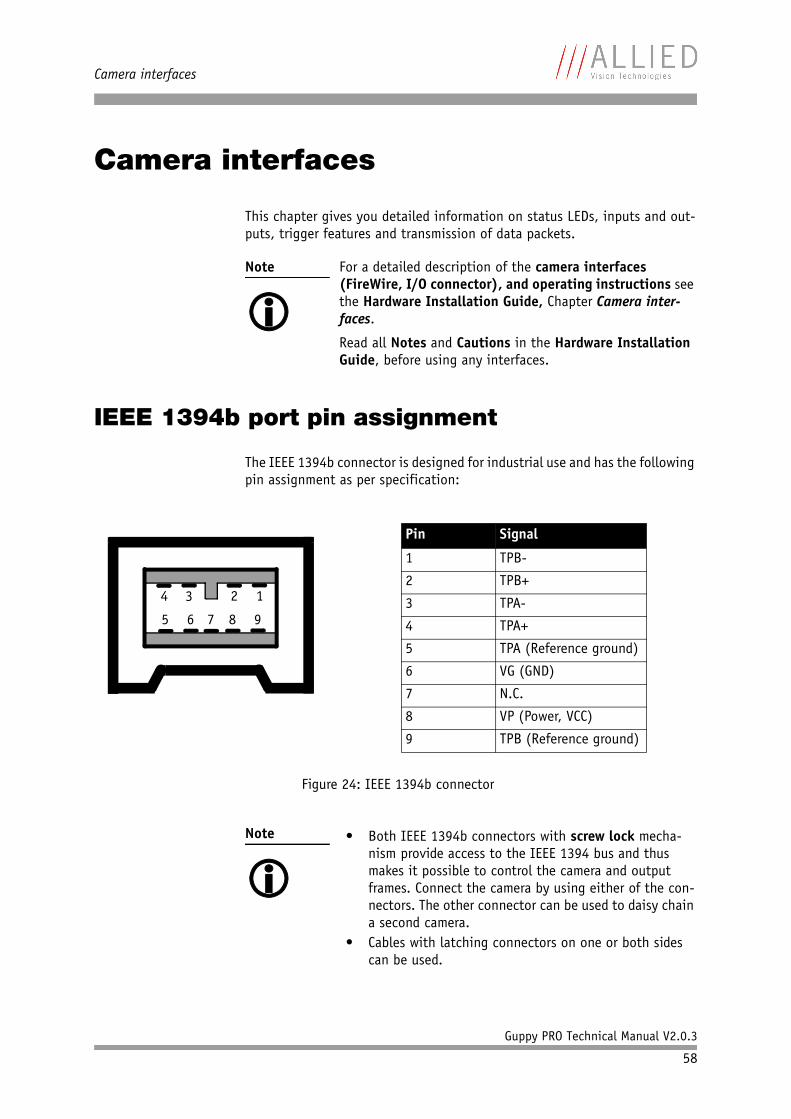
Camera interfaces
Guppy PRO Technical Manual V2.0.3
58
Camera interfaces
This chapter gives you detailed information on status LEDs, inputs and out-puts, trigger features and transmission of data packets.
IEEE 1394b port pin assignment
The IEEE 1394b connector is designed for industrial use and has the following pin assignment as per specification:
Note
For a detailed description of the camera interfaces (FireWire, I/O connector), and operating instructions see the Hardware Installation Guide, Chapter Camera inter-faces.
Read all Notes and Cautions in the Hardware Installation Guide, before using any interfaces.
Figure 24: IEEE 1394b connector
Note
• Both IEEE 1394b connectors with screw lock mecha-
nism provide access to the IEEE 1394 bus and thus makes it possible to control the camera and output frames. Connect the camera by using either of the con-nectors. The other connector can be used to daisy chain a second camera.
• Cables with latching connectors on one or both sides can be used.
1234
5 6 7 8 9
Pin Signal
1 TPB-
2 TPB+
3 TPA-
4 TPA+
5 TPA (Reference ground)
6 VG (GND)
7 N.C.
8 VP (Power, VCC)
9 TPB (Reference ground)
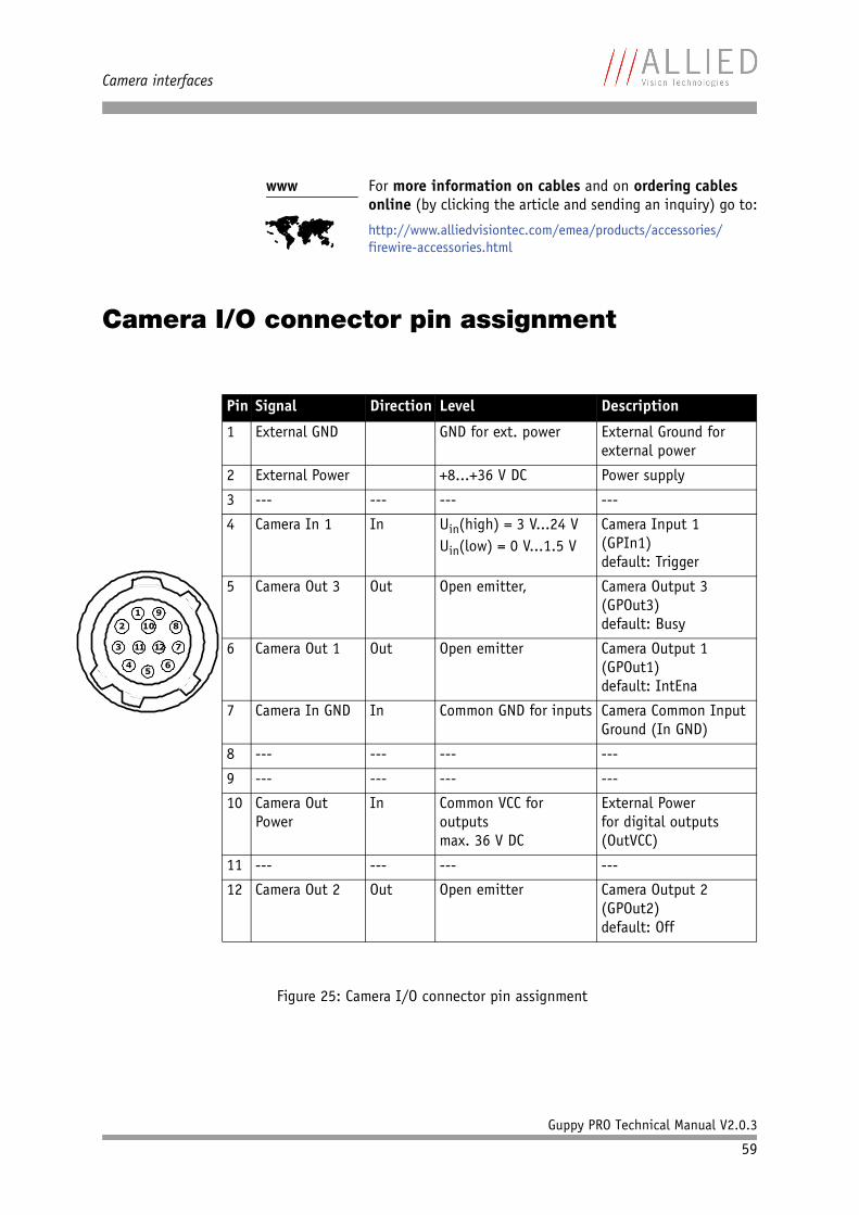
Camera interfaces
Guppy PRO Technical Manual V2.0.3
59
Camera I/O connector pin assignment
www
For more information on cables and on ordering cables online (by clicking the article and sending an inquiry) go to:
http://www.alliedvisiontec.com/emea/products/accessories/firewire-accessories.html
Figure 25: Camera I/O connector pin assignment
11029
8
7
6
12113
45
Pin Signal Direction Level Description
1 External GND GND for ext. power External Ground for external power
2 External Power +8...+36 V DC Power supply
3 --- --- --- ---
4 Camera In 1 In Uin(high) = 3 V...24 VUin(low) = 0 V...1.5 V
Camera Input 1(GPIn1)default: Trigger
5 Camera Out 3 Out Open emitter, Camera Output 3(GPOut3)default: Busy
6 Camera Out 1 Out Open emitter Camera Output 1(GPOut1)default: IntEna
7 Camera In GND In Common GND for inputs Camera Common Input Ground (In GND)
8 --- --- --- ---
9 --- --- --- ---
10 Camera Out Power
In Common VCC foroutputsmax. 36 V DC
External Powerfor digital outputs(OutVCC)
11 --- --- --- ---
12 Camera Out 2 Out Open emitter Camera Output 2(GPOut2)default: Off
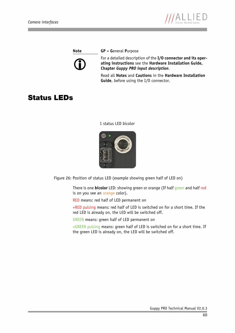
Camera interfaces
Guppy PRO Technical Manual V2.0.3
60
Status LEDs
There is one bicolor LED: showing green or orange (If half green and half red is on you see an orange color).
RED means: red half of LED permanent on
+RED pulsing means: red half of LED is switched on for a short time. If the red LED is already on, the LED will be switched off.
GREEN means: green half of LED permanent on
+GREEN pulsing means: green half of LED is switched on for a short time. If the green LED is already on, the LED will be switched off.
Note
GP = General Purpose
For a detailed description of the I/O connector and its oper-ating instructions see the Hardware Installation Guide, Chapter Guppy PRO input description.
Read all Notes and Cautions in the Hardware Installation Guide, before using the I/O connector.
Figure 26: Position of status LED (example showing green half of LED on)
1 status LED bicolor
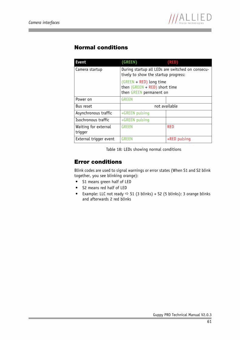
Camera interfaces
Guppy PRO Technical Manual V2.0.3
61
Normal conditions
Error conditionsBlink codes are used to signal warnings or error states (When S1 and S2 blink together, you see blinking orange):• S1 means green half of LED• S2 means red half of LED• Example: LLC not ready S1 (3 blinks) + S2 (5 blinks): 3 orange blinks
and afterwards 2 red blinks
Event (GREEN) (RED)
Camera startup During startup all LEDs are switched on consecu-tively to show the startup progress:
(GREEN + RED) long timethen (GREEN + RED) short timethen GREEN permanent on
Power on GREEN
Bus reset not available
Asynchronous traffic +GREEN pulsing
Isochronous traffic +GREEN pulsing
Waiting for external trigger
GREEN RED
External trigger event GREEN +RED pulsing
Table 18: LEDs showing normal conditions
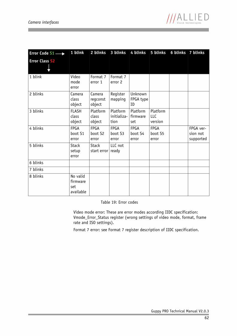
Camera interfaces
Guppy PRO Technical Manual V2.0.3
62
Video mode error: These are error modes according IIDC specification: Vmode_Error_Status register (wrong settings of video mode, format, frame rate and ISO settings).
Format 7 error: see Format 7 register description of IIDC specification.
Error Code S1
Error Class S2
1 blink 2 blinks 3 blinks 4 blinks 5 blinks 6 blinks 7 blinks
1 blink Video mode error
Format 7 error 1
Format 7 error 2
2 blinks Camera class object
Camera regconst object
Register mapping
Unknown FPGA type ID
3 blinks FLASH class object
Platform class object
Platform initializa-tion
Platform firmware set
Platform LLCversion
4 blinks FPGA boot S1 error
FPGA boot S2 error
FPGA boot S3 error
FPGA boot S4 error
FPGA boot S5 error
FPGA ver-sion not supported
5 blinks Stack setup error
Stack start error
LLC not ready
6 blinks
7 blinks
8 blinks No valid firmware setavailable
Table 19: Error codes
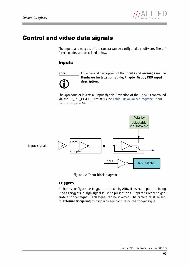
Camera interfaces
Guppy PRO Technical Manual V2.0.3
63
Control and video data signals
The inputs and outputs of the camera can be configured by software. The dif-ferent modes are described below.
Inputs
The optocoupler inverts all input signals. Inversion of the signal is controlled via the IO_INP_CTRL1..2 register (see Table 20: Advanced register: Input control on page 64).
Triggers
All inputs configured as triggers are linked by AND. If several inputs are being used as triggers, a high signal must be present on all inputs in order to gen-erate a trigger signal. Each signal can be inverted. The camera must be set to external triggering to trigger image capture by the trigger signal.
Note
For a general description of the inputs and warnings see the Hardware Installation Guide, Chapter Guppy PRO input description.
Figure 27: Input block diagram
Input
Polarity
selectablevia software
Input state
Opto-
Coupler
Input signal
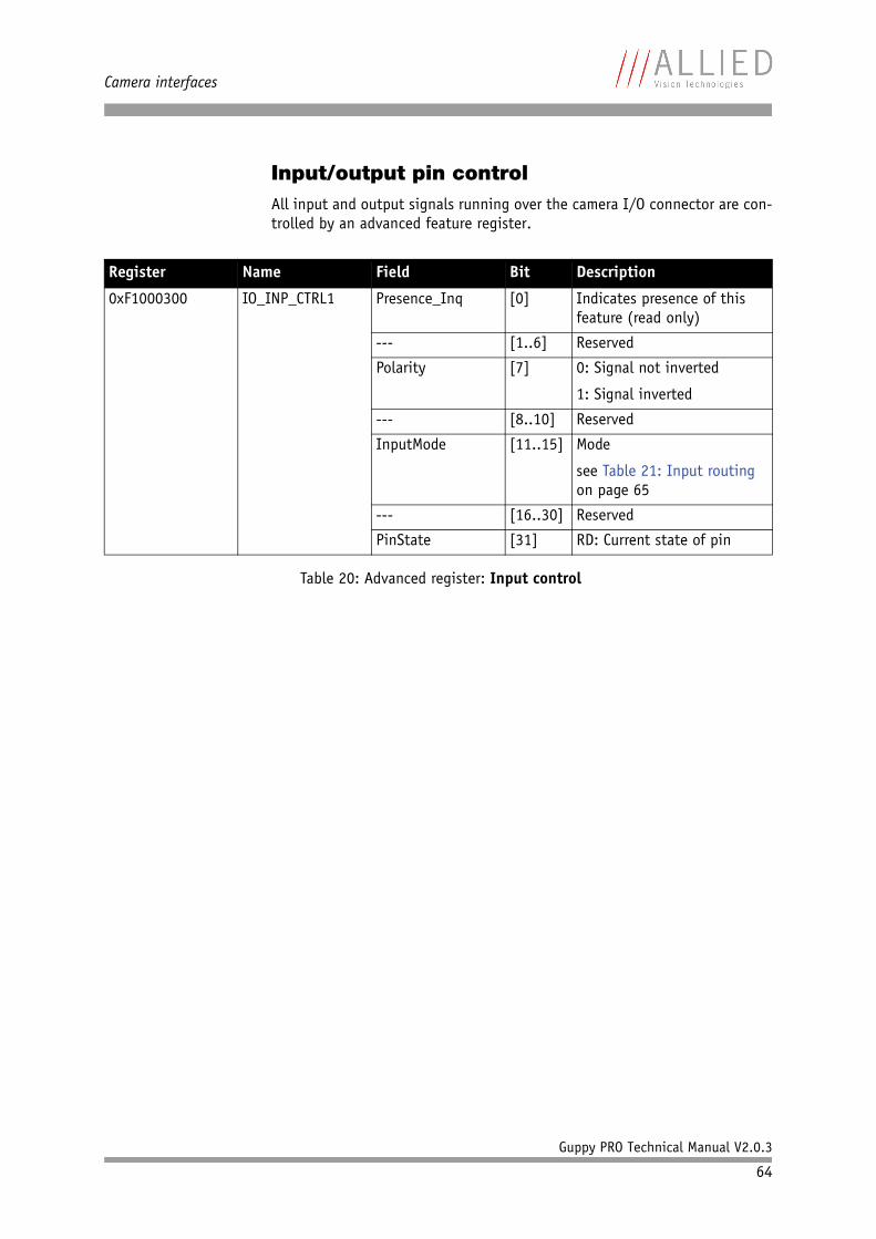
Camera interfaces
Guppy PRO Technical Manual V2.0.3
64
Input/output pin controlAll input and output signals running over the camera I/O connector are con-trolled by an advanced feature register.
Register Name Field Bit Description
0xF1000300 IO_INP_CTRL1 Presence_Inq [0] Indicates presence of this feature (read only)
--- [1..6] Reserved
Polarity [7] 0: Signal not inverted
1: Signal inverted
--- [8..10] Reserved
InputMode [11..15] Mode
see Table 21: Input routing on page 65
--- [16..30] Reserved
PinState [31] RD: Current state of pin
Table 20: Advanced register: Input control
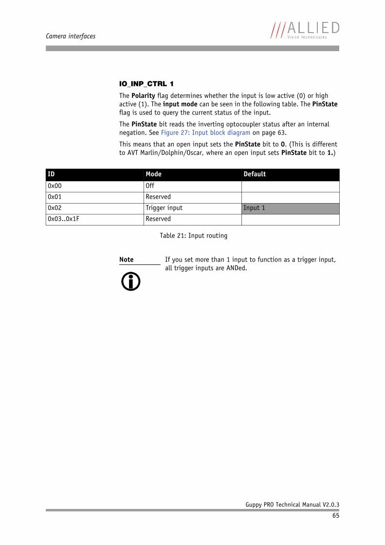
Camera interfaces
Guppy PRO Technical Manual V2.0.3
65
IO_INP_CTRL 1
The Polarity flag determines whether the input is low active (0) or high active (1). The input mode can be seen in the following table. The PinState flag is used to query the current status of the input.
The PinState bit reads the inverting optocoupler status after an internal negation. See Figure 27: Input block diagram on page 63.
This means that an open input sets the PinState bit to 0. (This is different to AVT Marlin/Dolphin/Oscar, where an open input sets PinState bit to 1.)
ID Mode Default
0x00 Off
0x01 Reserved
0x02 Trigger input Input 1
0x03..0x1F Reserved
Table 21: Input routing
Note
If you set more than 1 input to function as a trigger input, all trigger inputs are ANDed.
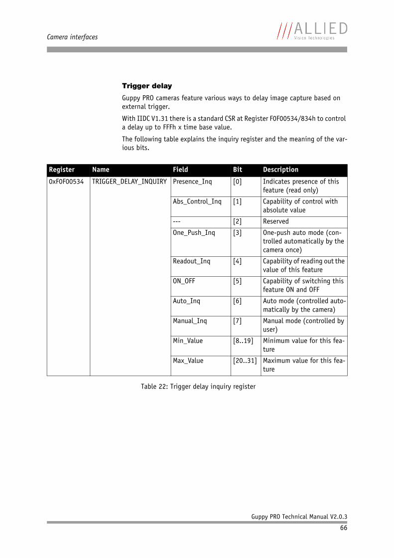
Camera interfaces
Guppy PRO Technical Manual V2.0.3
66
Trigger delay
Guppy PRO cameras feature various ways to delay image capture based on external trigger.
With IIDC V1.31 there is a standard CSR at Register F0F00534/834h to control a delay up to FFFh x time base value.
The following table explains the inquiry register and the meaning of the var-ious bits.
Register Name Field Bit Description
0xF0F00534 TRIGGER_DELAY_INQUIRY Presence_Inq [0] Indicates presence of this feature (read only)
Abs_Control_Inq [1] Capability of control with absolute value
--- [2] Reserved
One_Push_Inq [3] One-push auto mode (con-trolled automatically by the camera once)
Readout_Inq [4] Capability of reading out the value of this feature
ON_OFF [5] Capability of switching this feature ON and OFF
Auto_Inq [6] Auto mode (controlled auto-matically by the camera)
Manual_Inq [7] Manual mode (controlled by user)
Min_Value [8..19] Minimum value for this fea-ture
Max_Value [20..31] Maximum value for this fea-ture
Table 22: Trigger delay inquiry register
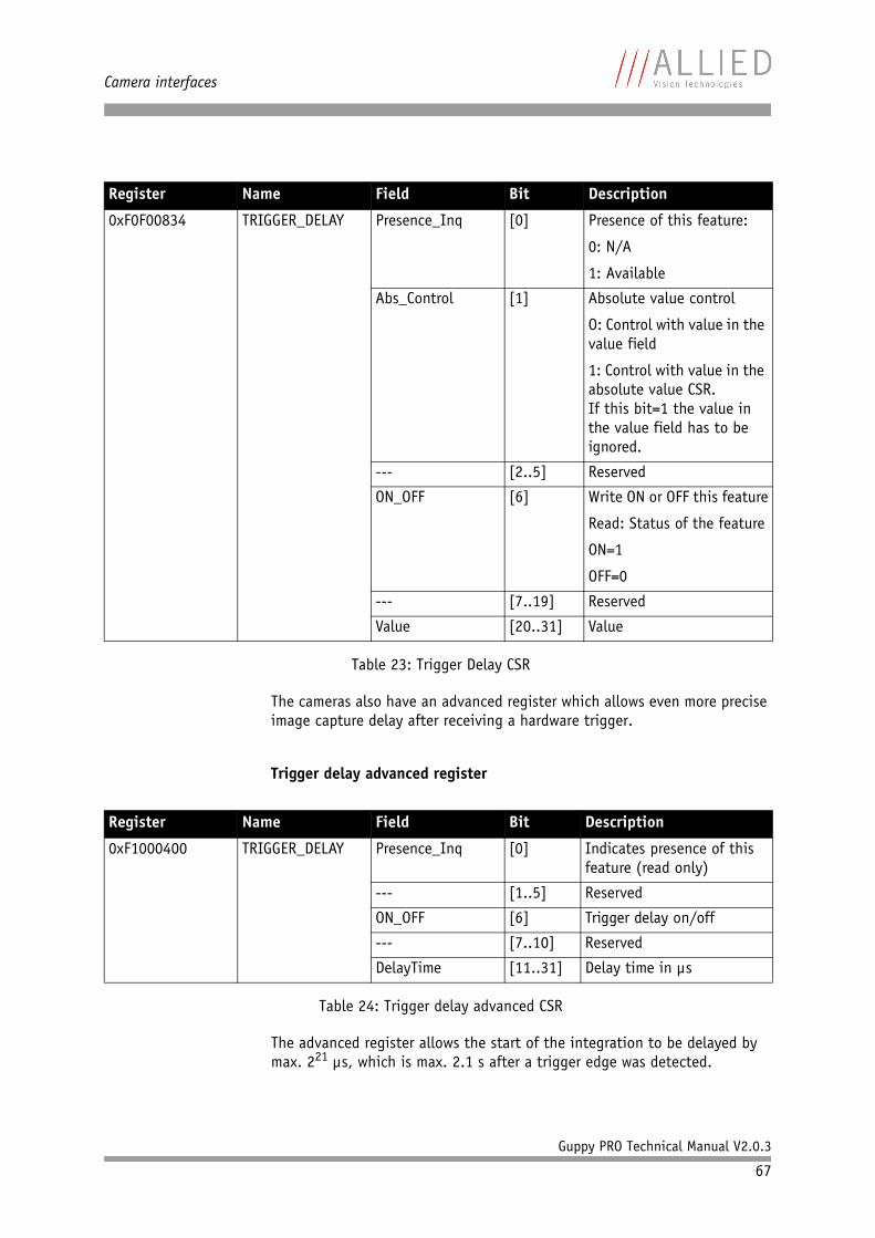
Camera interfaces
Guppy PRO Technical Manual V2.0.3
67
The cameras also have an advanced register which allows even more precise image capture delay after receiving a hardware trigger.
Trigger delay advanced register
The advanced register allows the start of the integration to be delayed by max. 221 µs, which is max. 2.1 s after a trigger edge was detected.
Register Name Field Bit Description
0xF0F00834 TRIGGER_DELAY Presence_Inq [0] Presence of this feature:
0: N/A
1: Available
Abs_Control [1] Absolute value control
O: Control with value in the value field
1: Control with value in the absolute value CSR.If this bit=1 the value in the value field has to be ignored.
--- [2..5] Reserved
ON_OFF [6] Write ON or OFF this feature
Read: Status of the feature
ON=1
OFF=0
--- [7..19] Reserved
Value [20..31] Value
Table 23: Trigger Delay CSR
Register Name Field Bit Description
0xF1000400 TRIGGER_DELAY Presence_Inq [0] Indicates presence of this feature (read only)
--- [1..5] Reserved
ON_OFF [6] Trigger delay on/off
--- [7..10] Reserved
DelayTime [11..31] Delay time in µs
Table 24: Trigger delay advanced CSR
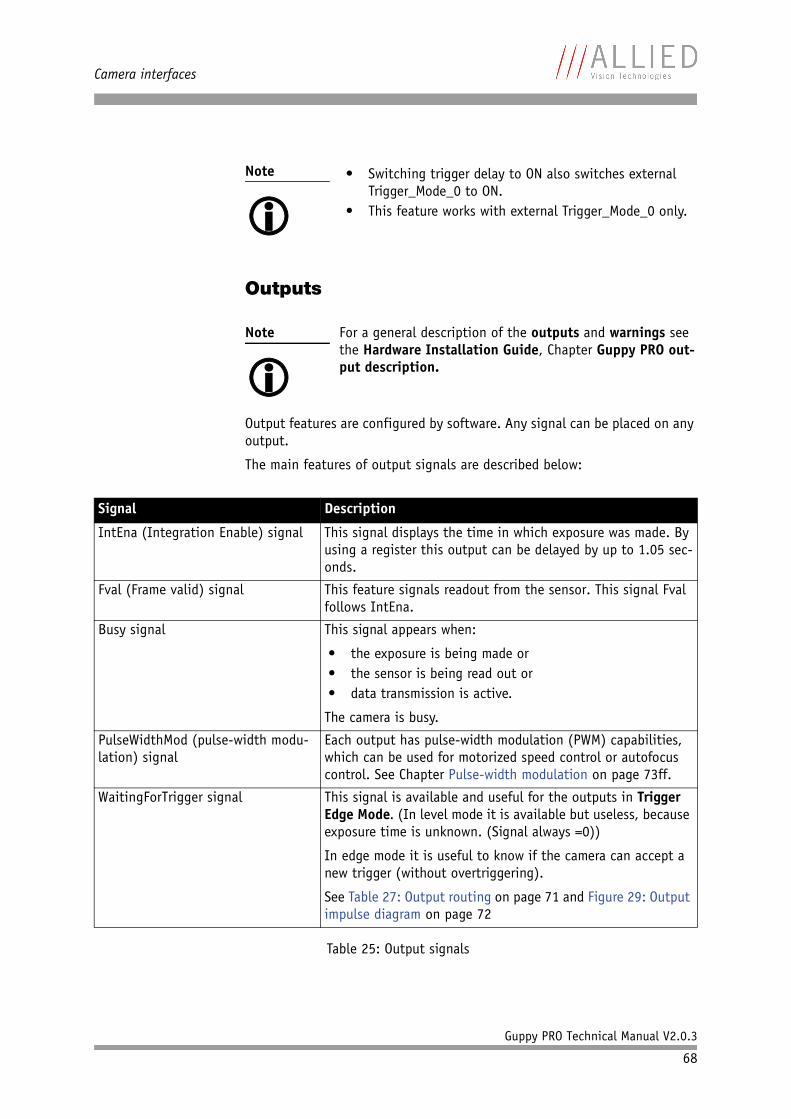
Camera interfaces
Guppy PRO Technical Manual V2.0.3
68
Outputs
Output features are configured by software. Any signal can be placed on any output.
The main features of output signals are described below:
Note
• Switching trigger delay to ON also switches external
Trigger_Mode_0 to ON.• This feature works with external Trigger_Mode_0 only.
Note
For a general description of the outputs and warnings see the Hardware Installation Guide, Chapter Guppy PRO out-put description.
Signal Description
IntEna (Integration Enable) signal This signal displays the time in which exposure was made. By using a register this output can be delayed by up to 1.05 sec-onds.
Fval (Frame valid) signal This feature signals readout from the sensor. This signal Fval follows IntEna.
Busy signal This signal appears when:
• the exposure is being made or• the sensor is being read out or• data transmission is active.
The camera is busy.
PulseWidthMod (pulse-width modu-lation) signal
Each output has pulse-width modulation (PWM) capabilities, which can be used for motorized speed control or autofocus control. See Chapter Pulse-width modulation on page 73ff.
WaitingForTrigger signal This signal is available and useful for the outputs in Trigger Edge Mode. (In level mode it is available but useless, because exposure time is unknown. (Signal always =0))
In edge mode it is useful to know if the camera can accept a new trigger (without overtriggering).
See Table 27: Output routing on page 71 and Figure 29: Output impulse diagram on page 72
Table 25: Output signals
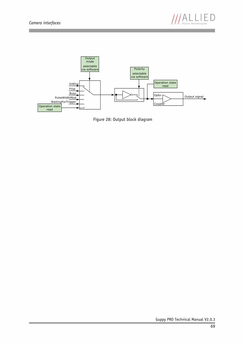
Camera interfaces
Guppy PRO Technical Manual V2.0.3
69
Figure 28: Output block diagram
IntEna
Output signalOpto-
Coupler
Polarity
selectablevia software
Operation state read
Output mode
selectablevia software
FValBusy
PulseWidthModWaitingForTrigger
Operation state read
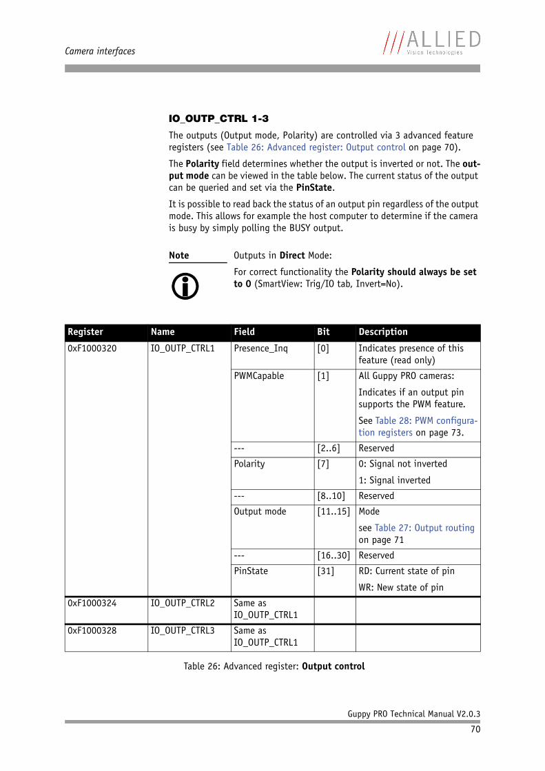
Camera interfaces
Guppy PRO Technical Manual V2.0.3
70
IO_OUTP_CTRL 1-3
The outputs (Output mode, Polarity) are controlled via 3 advanced feature registers (see Table 26: Advanced register: Output control on page 70).
The Polarity field determines whether the output is inverted or not. The out-put mode can be viewed in the table below. The current status of the output can be queried and set via the PinState.
It is possible to read back the status of an output pin regardless of the output mode. This allows for example the host computer to determine if the camera is busy by simply polling the BUSY output.
Note
Outputs in Direct Mode:
For correct functionality the Polarity should always be set to 0 (SmartView: Trig/IO tab, Invert=No).
Register Name Field Bit Description
0xF1000320 IO_OUTP_CTRL1 Presence_Inq [0] Indicates presence of this feature (read only)
PWMCapable [1] All Guppy PRO cameras:
Indicates if an output pin supports the PWM feature.
See Table 28: PWM configura-tion registers on page 73.
--- [2..6] Reserved
Polarity [7] 0: Signal not inverted
1: Signal inverted
--- [8..10] Reserved
Output mode [11..15] Mode
see Table 27: Output routing on page 71
--- [16..30] Reserved
PinState [31] RD: Current state of pin
WR: New state of pin
0xF1000324 IO_OUTP_CTRL2 Same as IO_OUTP_CTRL1
0xF1000328 IO_OUTP_CTRL3 Same as IO_OUTP_CTRL1
Table 26: Advanced register: Output control
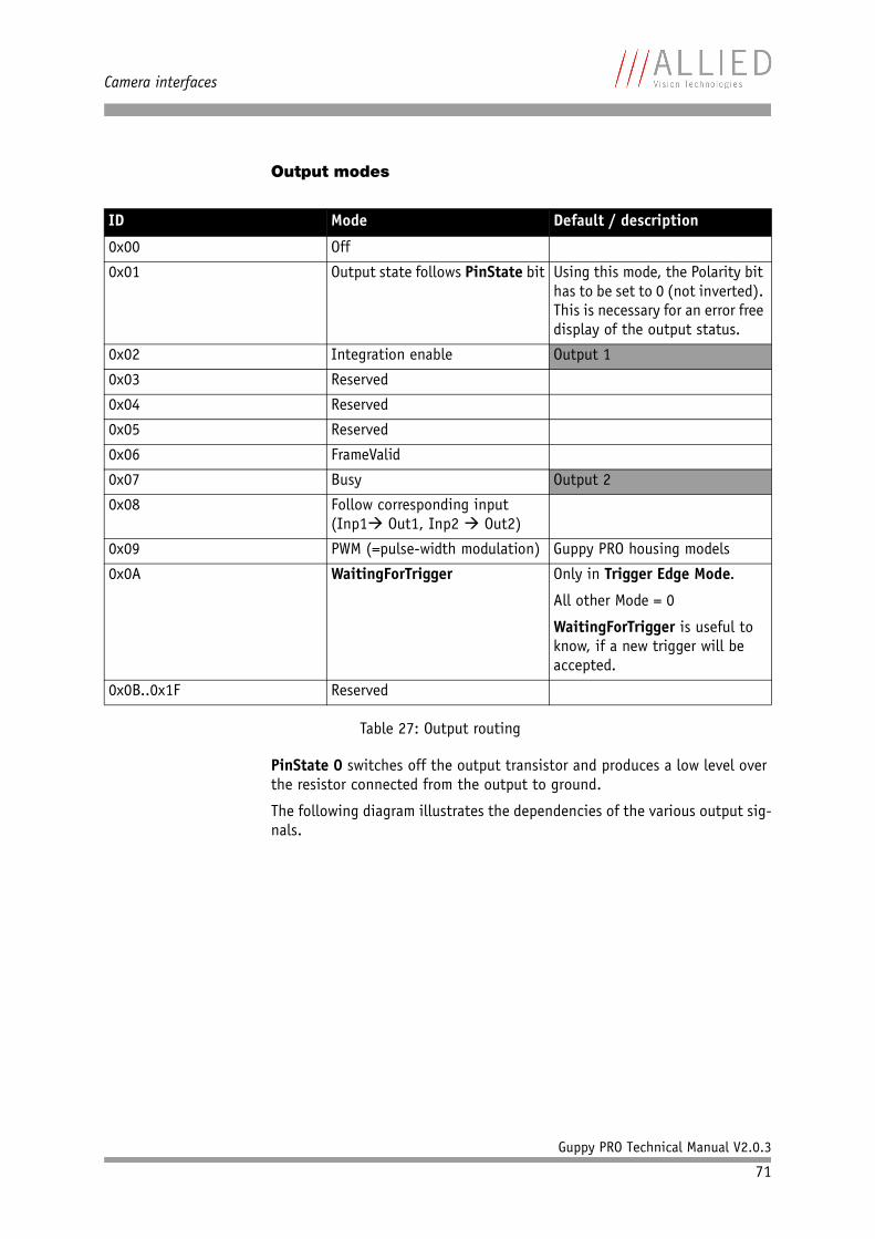
Camera interfaces
Guppy PRO Technical Manual V2.0.3
71
Output modes
PinState 0 switches off the output transistor and produces a low level over the resistor connected from the output to ground.
The following diagram illustrates the dependencies of the various output sig-nals.
ID Mode Default / description
0x00 Off
0x01 Output state follows PinState bit Using this mode, the Polarity bit has to be set to 0 (not inverted). This is necessary for an error free display of the output status.
0x02 Integration enable Output 1
0x03 Reserved
0x04 Reserved
0x05 Reserved
0x06 FrameValid
0x07 Busy Output 2
0x08 Follow corresponding input(Inp1 Out1, Inp2 Out2)
0x09 PWM (=pulse-width modulation) Guppy PRO housing models
0x0A WaitingForTrigger Only in Trigger Edge Mode.
All other Mode = 0
WaitingForTrigger is useful to know, if a new trigger will be accepted.
0x0B..0x1F Reserved
Table 27: Output routing
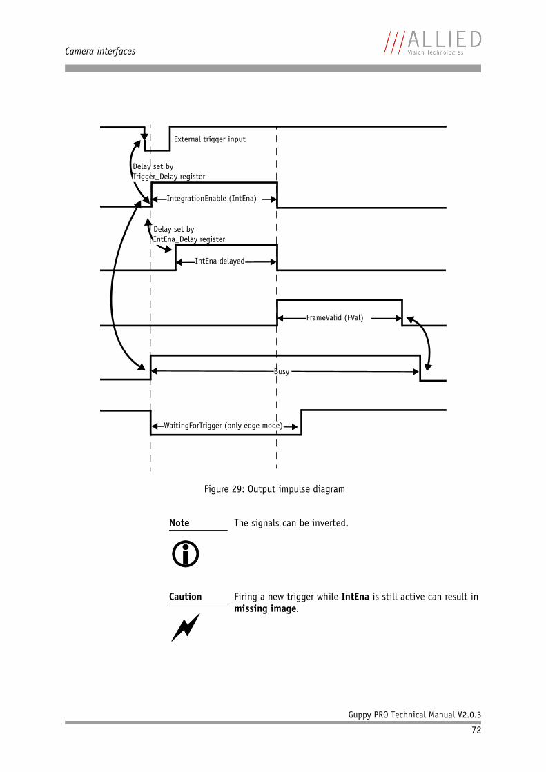
Camera interfaces
Guppy PRO Technical Manual V2.0.3
72
Figure 29: Output impulse diagram
Note
The signals can be inverted.
Caution
Firing a new trigger while IntEna is still active can result in missing image.
External trigger input
IntEna delayed
IntegrationEnable (IntEna)
Busy
FrameValid (FVal)
Delay set byTrigger_Delay register
Delay set byIntEna_Delay register
WaitingForTrigger (only edge mode)
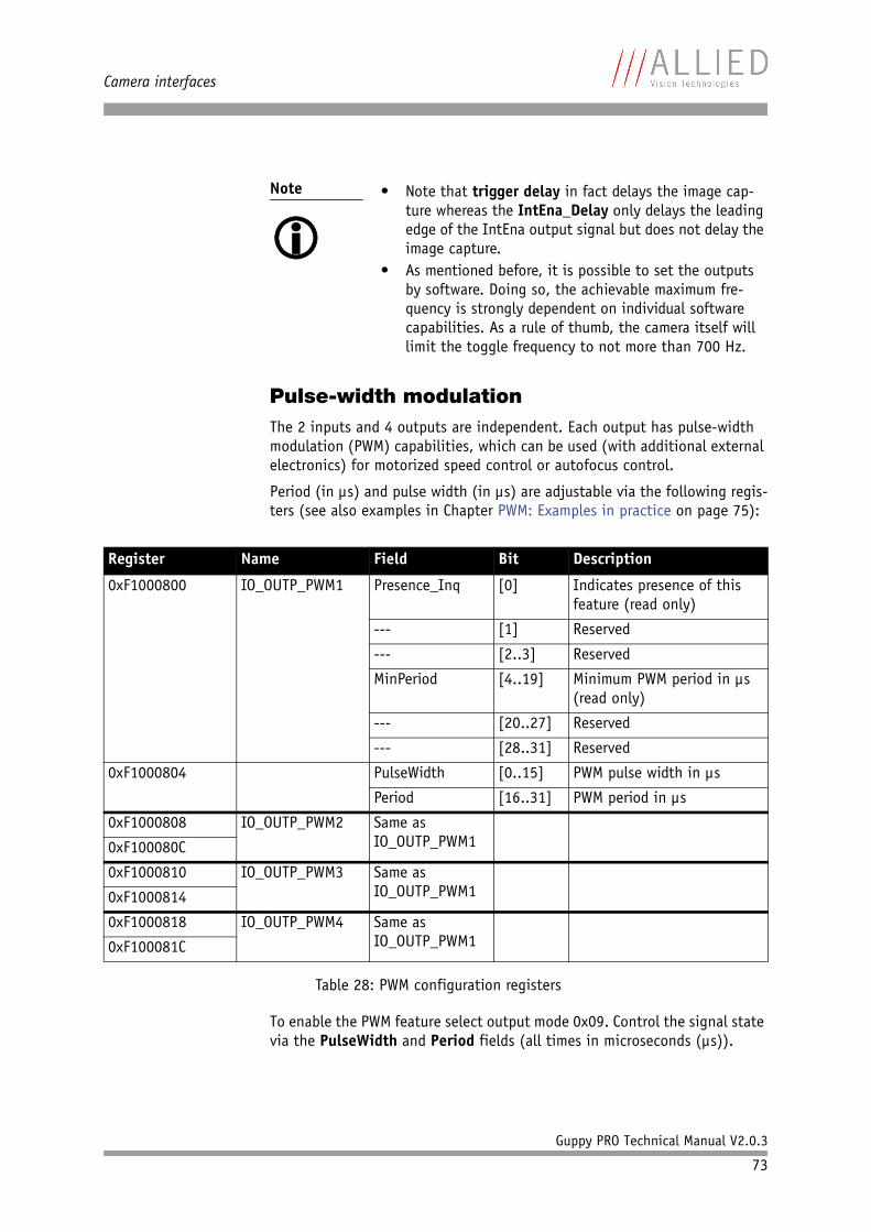
Camera interfaces
Guppy PRO Technical Manual V2.0.3
73
Pulse-width modulationThe 2 inputs and 4 outputs are independent. Each output has pulse-width modulation (PWM) capabilities, which can be used (with additional external electronics) for motorized speed control or autofocus control.
Period (in µs) and pulse width (in µs) are adjustable via the following regis-ters (see also examples in Chapter PWM: Examples in practice on page 75):
To enable the PWM feature select output mode 0x09. Control the signal state via the PulseWidth and Period fields (all times in microseconds (µs)).
Note
• Note that trigger delay in fact delays the image cap-
ture whereas the IntEna_Delay only delays the leading edge of the IntEna output signal but does not delay the image capture.
• As mentioned before, it is possible to set the outputs by software. Doing so, the achievable maximum fre-quency is strongly dependent on individual software capabilities. As a rule of thumb, the camera itself will limit the toggle frequency to not more than 700 Hz.
Register Name Field Bit Description
0xF1000800 IO_OUTP_PWM1 Presence_Inq [0] Indicates presence of this feature (read only)
--- [1] Reserved
--- [2..3] Reserved
MinPeriod [4..19] Minimum PWM period in µs (read only)
--- [20..27] Reserved
--- [28..31] Reserved
0xF1000804 PulseWidth [0..15] PWM pulse width in µs
Period [16..31] PWM period in µs
0xF1000808 IO_OUTP_PWM2 Same as IO_OUTP_PWM10xF100080C
0xF1000810 IO_OUTP_PWM3 Same as IO_OUTP_PWM10xF1000814
0xF1000818 IO_OUTP_PWM4 Same as IO_OUTP_PWM10xF100081C
Table 28: PWM configuration registers
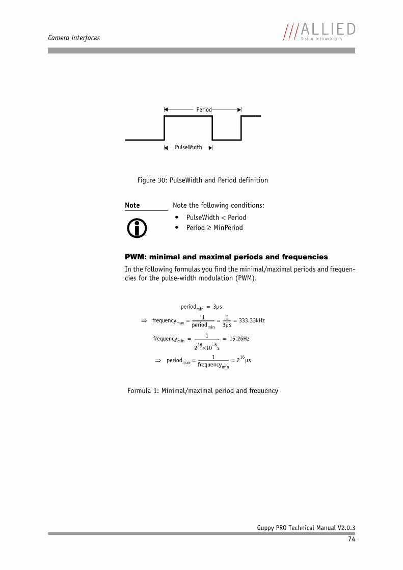
Camera interfaces
Guppy PRO Technical Manual V2.0.3
74
PWM: minimal and maximal periods and frequencies
In the following formulas you find the minimal/maximal periods and frequen-cies for the pulse-width modulation (PWM).
Figure 30: PulseWidth and Period definition
Note
Note the following conditions:
• PulseWidth Period• Period MinPeriod
Formula 1: Minimal/maximal period and frequency
PulseWidth
Period
periodmin 3µs=
frequencymax1
periodmin---------------------- 1
3µs-------- 333.33kHz= = =
frequencymin1
216 6–10 s
------------------------- 15.26Hz= =
periodmax1
frequencymin------------------------------ 216µs= =
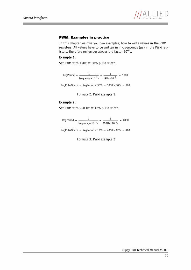
Camera interfaces
Guppy PRO Technical Manual V2.0.3
75
PWM: Examples in practice
In this chapter we give you two examples, how to write values in the PWM registers. All values have to be written in microseconds (µs) in the PWM reg-isters, therefore remember always the factor 10-6s.
Example 1:
Set PWM with 1kHz at 30% pulse width.
Example 2:
Set PWM with 250 Hz at 12% pulse width.
Formula 2: PWM example 1
Formula 3: PWM example 2
RegPeriod 1
frequency 6–10 s---------------------------------------- 1
1kHz 6–10 s----------------------------- 1000= = =
RegPulseWidth RegPeriod 30% 1000 30% 300= = =
RegPeriod 1
frequency 6–10 s---------------------------------------- 1
250Hz 6–10 s-------------------------------- 4000= = =
RegPulseWidth RegPeriod 12% 4000 12% 480= = =
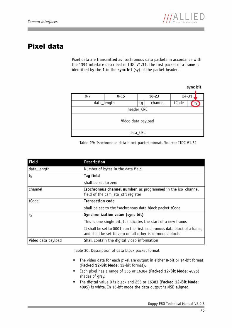
Camera interfaces
Guppy PRO Technical Manual V2.0.3
76
Pixel data
Pixel data are transmitted as isochronous data packets in accordance with the 1394 interface described in IIDC V1.31. The first packet of a frame is identified by the 1 in the sync bit (sy) of the packet header.
• The video data for each pixel are output in either 8-bit or 14-bit format (Packed 12-Bit Mode: 12-bit format).
• Each pixel has a range of 256 or 16384 (Packed 12-Bit Mode: 4096) shades of grey.
• The digital value 0 is black and 255 or 16383 (Packed 12-Bit Mode: 4095) is white. In 16-bit mode the data output is MSB aligned.
Field Description
data_length Number of bytes in the data field
tg Tag field
shall be set to zero
channel Isochronous channel number, as programmed in the iso_channel field of the cam_sta_ctrl register
tCode Transaction code
shall be set to the isochronous data block packet tCode
sy Synchronization value (sync bit)
This is one single bit. It indicates the start of a new frame.
It shall be set to 0001h on the first isochronous data block of a frame, and shall be set to zero on all other isochronous blocks
Video data payload Shall contain the digital video information
Table 30: Description of data block packet format
0-7 8-15 16-23 24-31
data_length tg channel tCode sy
header_CRC
Video data payload
data_CRC
Table 29: Isochronous data block packet format. Source: IIDC V1.31
sync bit
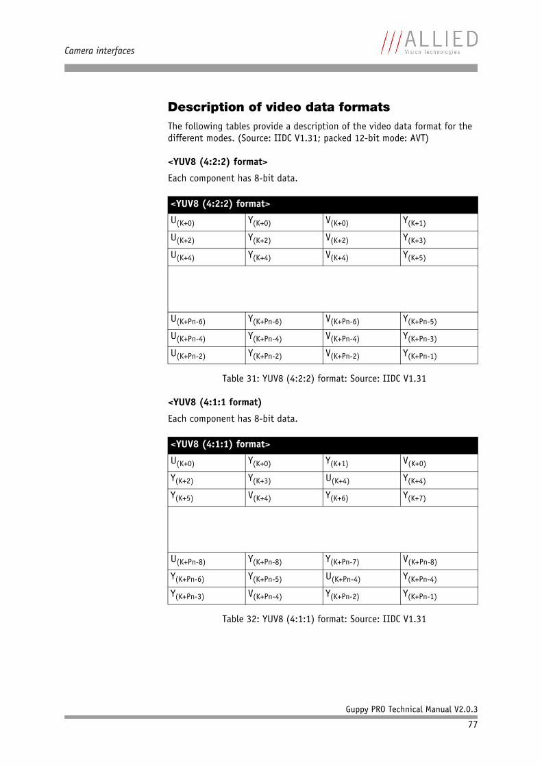
Camera interfaces
Guppy PRO Technical Manual V2.0.3
77
Description of video data formatsThe following tables provide a description of the video data format for the different modes. (Source: IIDC V1.31; packed 12-bit mode: AVT)
<YUV8 (4:2:2) format>
Each component has 8-bit data.
<YUV8 (4:1:1 format)
Each component has 8-bit data.
<YUV8 (4:2:2) format>
U(K+0) Y(K+0) V(K+0) Y(K+1)
U(K+2) Y(K+2) V(K+2) Y(K+3)
U(K+4) Y(K+4) V(K+4) Y(K+5)
U(K+Pn-6) Y(K+Pn-6) V(K+Pn-6) Y(K+Pn-5)
U(K+Pn-4) Y(K+Pn-4) V(K+Pn-4) Y(K+Pn-3)
U(K+Pn-2) Y(K+Pn-2) V(K+Pn-2) Y(K+Pn-1)
Table 31: YUV8 (4:2:2) format: Source: IIDC V1.31
<YUV8 (4:1:1) format>
U(K+0) Y(K+0) Y(K+1) V(K+0)
Y(K+2) Y(K+3) U(K+4) Y(K+4)
Y(K+5) V(K+4) Y(K+6) Y(K+7)
U(K+Pn-8) Y(K+Pn-8) Y(K+Pn-7) V(K+Pn-8)
Y(K+Pn-6) Y(K+Pn-5) U(K+Pn-4) Y(K+Pn-4)
Y(K+Pn-3) V(K+Pn-4) Y(K+Pn-2) Y(K+Pn-1)
Table 32: YUV8 (4:1:1) format: Source: IIDC V1.31
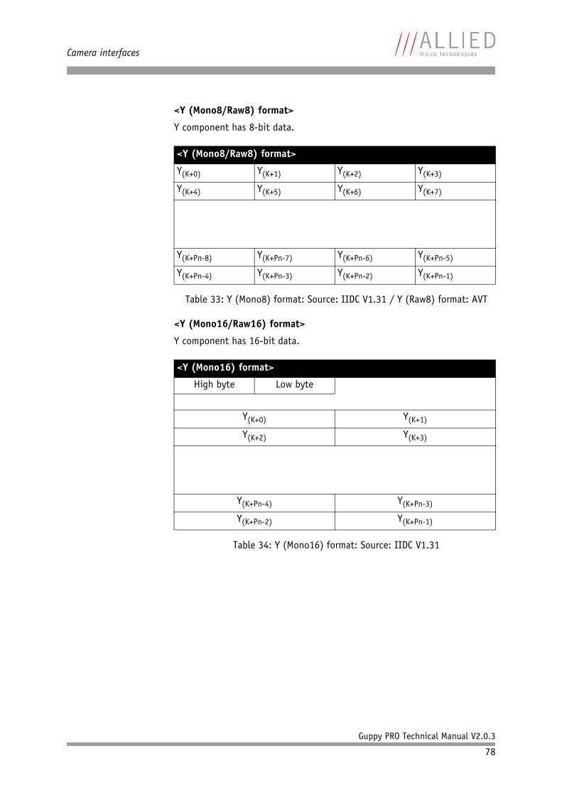
Camera interfaces
Guppy PRO Technical Manual V2.0.3
78
<Y (Mono8/Raw8) format>
Y component has 8-bit data.
<Y (Mono16/Raw16) format>
Y component has 16-bit data.
<Y (Mono8/Raw8) format>
Y(K+0) Y(K+1) Y(K+2) Y(K+3)
Y(K+4) Y(K+5) Y(K+6) Y(K+7)
Y(K+Pn-8) Y(K+Pn-7) Y(K+Pn-6) Y(K+Pn-5)
Y(K+Pn-4) Y(K+Pn-3) Y(K+Pn-2) Y(K+Pn-1)
Table 33: Y (Mono8) format: Source: IIDC V1.31 / Y (Raw8) format: AVT
<Y (Mono16) format>
High byte Low byte
Y(K+0) Y(K+1)
Y(K+2) Y(K+3)
Y(K+Pn-4) Y(K+Pn-3)
Y(K+Pn-2) Y(K+Pn-1)
Table 34: Y (Mono16) format: Source: IIDC V1.31
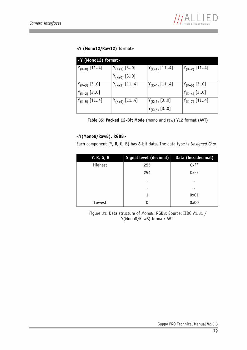
Camera interfaces
Guppy PRO Technical Manual V2.0.3
79
<Y (Mono12/Raw12) format>
<Y(Mono8/Raw8), RGB8>
Each component (Y, R, G, B) has 8-bit data. The data type is Unsigned Char.
<Y (Mono12) format>
Y(K+0) [11..4] Y(K+1) [3..0]
Y(K+0) [3..0]
Y(K+1) [11..4] Y(K+2) [11..4]
Y(K+3) [3..0]
Y(K+2) [3..0]
Y(K+3) [11..4] Y(K+4) [11..4] Y(K+5) [3..0]
Y(K+4) [3..0]
Y(K+5) [11..4] Y(K+6) [11..4] Y(K+7) [3..0]
Y(K+6) [3..0]
Y(K+7) [11..4]
Table 35: Packed 12-Bit Mode (mono and raw) Y12 format (AVT)
Y, R, G, B Signal level (decimal) Data (hexadecimal)
Highest
Lowest
255
254
.
.
1
0
0xFF
0xFE
.
.
0x01
0x00
Figure 31: Data structure of Mono8, RGB8; Source: IIDC V1.31 /Y(Mono8/Raw8) format: AVT
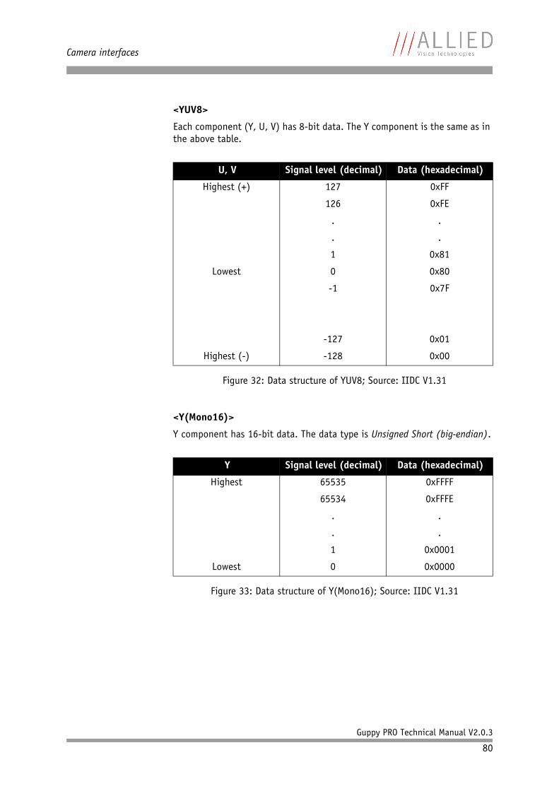
Camera interfaces
Guppy PRO Technical Manual V2.0.3
80
<YUV8>
Each component (Y, U, V) has 8-bit data. The Y component is the same as in the above table.
<Y(Mono16)>
Y component has 16-bit data. The data type is Unsigned Short (big-endian).
U, V Signal level (decimal) Data (hexadecimal)
Highest (+)
Lowest
Highest (-)
127
126
.
.
1
0
-1
-127
-128
0xFF
0xFE
.
.
0x81
0x80
0x7F
0x01
0x00
Figure 32: Data structure of YUV8; Source: IIDC V1.31
Y Signal level (decimal) Data (hexadecimal)
Highest
Lowest
65535
65534
.
.
1
0
0xFFFF
0xFFFE
.
.
0x0001
0x0000
Figure 33: Data structure of Y(Mono16); Source: IIDC V1.31

Camera interfaces
Guppy PRO Technical Manual V2.0.3
81
<Y(Mono12)>
Y component has 12-bit data. The data type is unsigned.
Y Signal level (decimal) Data (hexadecimal)
Highest
Lowest
4095
4094
.
.
1
0
0x0FFF
0x0FFE
.
.
0x0001
0x0000
Table 36: Data structure of Packed 12-Bit Mode (mono and raw) (AVT)
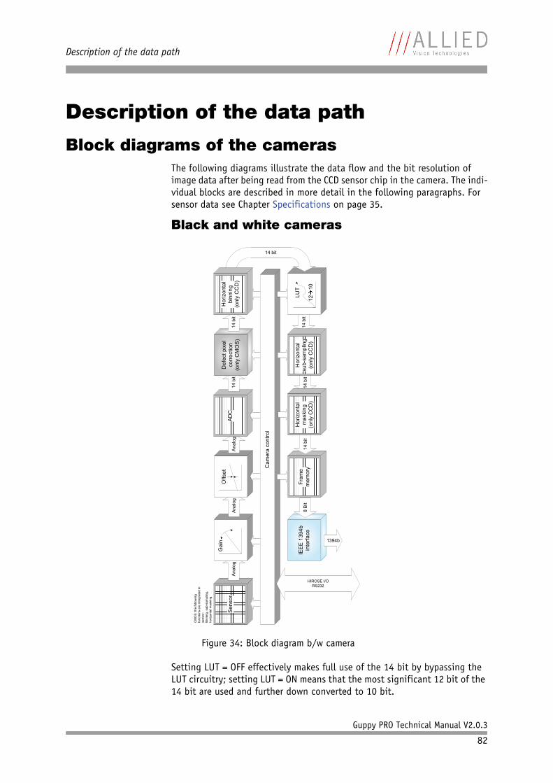
Description of the data path
Guppy PRO Technical Manual V2.0.3
82
Description of the data path
Block diagrams of the camerasThe following diagrams illustrate the data flow and the bit resolution of image data after being read from the CCD sensor chip in the camera. The indi-vidual blocks are described in more detail in the following paragraphs. For sensor data see Chapter Specifications on page 35.
Black and white cameras
Setting LUT = OFF effectively makes full use of the 14 bit by bypassing the LUT circuitry; setting LUT = ON means that the most significant 12 bit of the 14 bit are used and further down converted to 10 bit.
Figure 34: Block diagram b/w camera
Sen
sor
Ana
log
G
ain
Anal
og
Offs
et
Ana
log
AD
C
IEE
E 1
394b
in
terfa
ce
1394b
14 b
it
Def
ect p
ixel
co
rrect
ion
(onl
y C
MO
S)
14 b
it
Cam
era
cont
rol
HIROSE I/ORS232
8 B
itFr
ame
mem
ory
14 b
it14
bit
14 b
it L
UT
12
10
14 bit
CM
OS:
the
follo
win
g fu
nctio
ns a
re in
tegr
ated
in
sens
or:
Bin
ning
, sub
-sam
plin
g,
horiz
onta
l mas
king
Hor
izon
tal
sub-
sam
plin
g(o
nly
CC
D)
Hor
izon
tal
binn
ing
(onl
y C
CD
)
Hor
izon
tal
mas
king
(onl
y C
CD
)
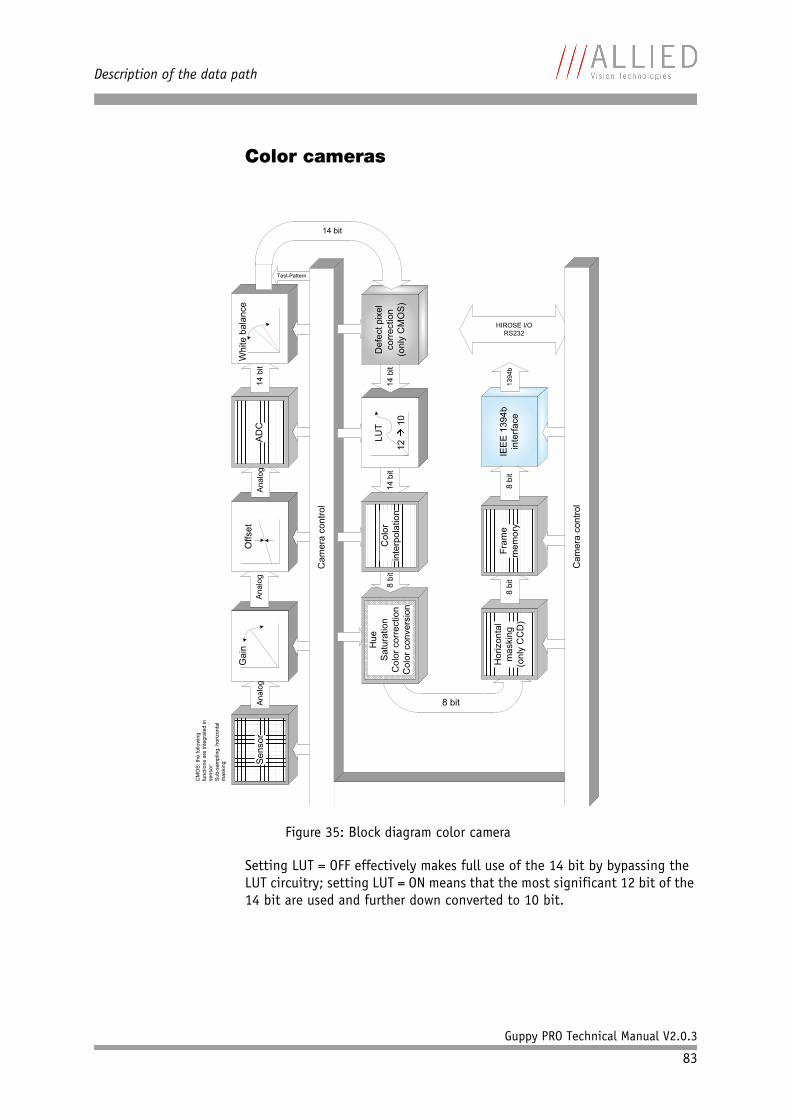
Description of the data path
Guppy PRO Technical Manual V2.0.3
83
Color cameras
Setting LUT = OFF effectively makes full use of the 14 bit by bypassing the LUT circuitry; setting LUT = ON means that the most significant 12 bit of the 14 bit are used and further down converted to 10 bit.
Figure 35: Block diagram color camera
Sen
sor
Ana
log
G
ain
Ana
log
Offs
etA
nalo
g14
bit
Whi
te b
alan
ce
HIROSE I/ORS232
Test-Pattern
8 bit
Cam
era
cont
rol
14 b
itLU
T
12 1
014
bit
Def
ect p
ixel
co
rrec
tion
(onl
y C
MO
S)
14 bit
Hor
izon
tal
mas
king
(onl
y C
CD
)
AD
C
CM
OS
: the
follo
win
g fu
nctio
ns a
re in
tegr
ated
in
sens
or:
Sub
-sam
plin
g, h
oriz
onta
l m
aski
ng
Hue
Sat
urat
ion
Col
or c
orre
ctio
nC
olor
con
vers
ion
8 bi
tC
olor
inte
rpol
atio
n
8 bi
tFr
ame
mem
ory
8 bi
tIE
EE
139
4b
inte
rface
1394
b
Cam
era
cont
rol
Description of the data path
Guppy PRO Technical Manual V2.0.3
84
White balance
There are two types of white balance:• one-push white balance: white balance is done only once (not contin-
uously)• auto white balance (AWB): continuously optimizes the color character-
istics of the image
Guppy PRO color cameras have both one-push white balance and auto white balance.
White balance is applied so that non-colored image parts are displayed non-colored.
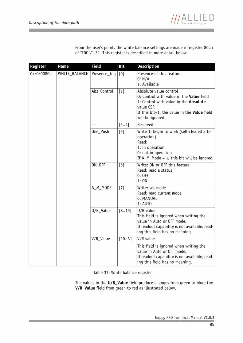
Description of the data path
Guppy PRO Technical Manual V2.0.3
85
From the user's point, the white balance settings are made in register 80Ch of IIDC V1.31. This register is described in more detail below.
The values in the U/B_Value field produce changes from green to blue; the V/R_Value field from green to red as illustrated below.
Register Name Field Bit Description
0xF0F0080C WHITE_BALANCE Presence_Inq [0] Presence of this feature:0: N/A1: Available
Abs_Control [1] Absolute value controlO: Control with value in the Value field1: Control with value in the Absolute value CSRIf this bit=1, the value in the Value field will be ignored.
--- [2..4] Reserved
One_Push [5] Write 1: begin to work (self-cleared after operation)Read:1: in operation0: not in operationIf A_M_Mode = 1, this bit will be ignored.
ON_OFF [6] Write: ON or OFF this featureRead: read a status0: OFF1: ON
A_M_MODE [7] Write: set modeRead: read current mode0: MANUAL1: AUTO
U/B_Value [8..19] U/B valueThis field is ignored when writing the value in Auto or OFF mode.If readout capability is not available, read-ing this field has no meaning.
V/R_Value [20..31] V/R value
This field is ignored when writing the value in Auto or OFF mode.If readout capability is not available, read-ing this field has no meaning.
Table 37: White balance register
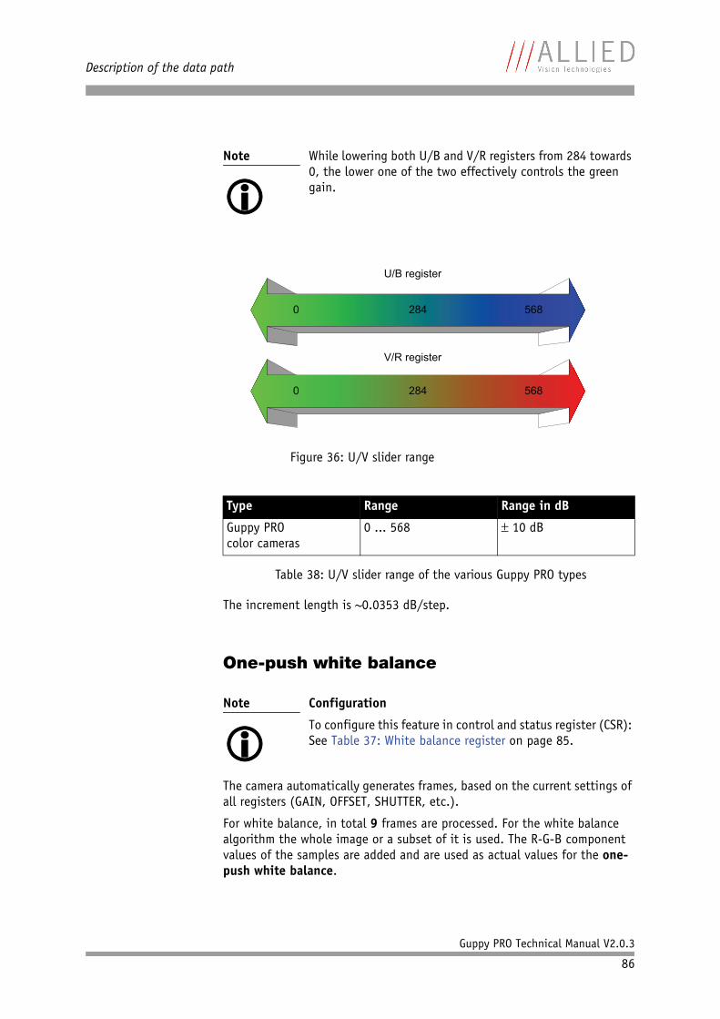
Description of the data path
Guppy PRO Technical Manual V2.0.3
86
The increment length is ~0.0353 dB/step.
One-push white balance
The camera automatically generates frames, based on the current settings of all registers (GAIN, OFFSET, SHUTTER, etc.).
For white balance, in total 9 frames are processed. For the white balance algorithm the whole image or a subset of it is used. The R-G-B component values of the samples are added and are used as actual values for the one-push white balance.
Note
While lowering both U/B and V/R registers from 284 towards 0, the lower one of the two effectively controls the green gain.
Figure 36: U/V slider range
Type Range Range in dB
Guppy PROcolor cameras
0 ... 568 10 dB
Table 38: U/V slider range of the various Guppy PRO types
Note
Configuration
To configure this feature in control and status register (CSR): See Table 37: White balance register on page 85.
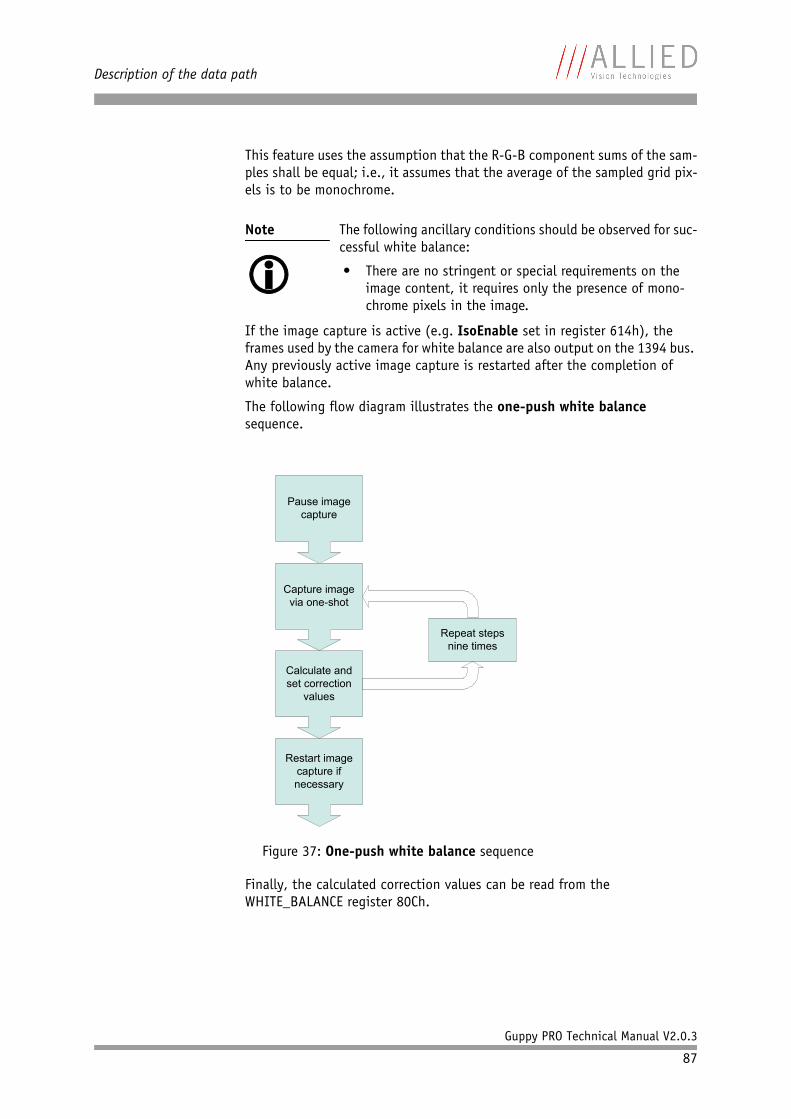
Description of the data path
Guppy PRO Technical Manual V2.0.3
87
This feature uses the assumption that the R-G-B component sums of the sam-ples shall be equal; i.e., it assumes that the average of the sampled grid pix-els is to be monochrome.
If the image capture is active (e.g. IsoEnable set in register 614h), the frames used by the camera for white balance are also output on the 1394 bus. Any previously active image capture is restarted after the completion of white balance.
The following flow diagram illustrates the one-push white balance sequence.
Finally, the calculated correction values can be read from the WHITE_BALANCE register 80Ch.
Note
The following ancillary conditions should be observed for suc-cessful white balance:
• There are no stringent or special requirements on the image content, it requires only the presence of mono-chrome pixels in the image.
Figure 37: One-push white balance sequence
Pause image capture
Capture image via one-shot
Calculate and set correction
values
Restart image capture if necessary
Repeat steps nine times
Description of the data path
Guppy PRO Technical Manual V2.0.3
88
Auto white balance (AWB)The auto white balance feature continuously optimizes the color character-istics of the image.
For the white balance algorithm the whole image or a subset of it is used.
Auto white balance can also be enabled by using an external trigger. How-ever, if there is a pause of >10 seconds between capturing individual frames this process is aborted.
AUTOFNC_AOI affects the auto shutter, auto gain and auto white balance fea-tures and is independent of the Format_7 AOI settings. If this feature is switched off the work area position and size will follow the current active image size.
Within this area, the R-G-B component values of the samples are added and used as actual values for the feedback.
The following drawing illustrates the AUTOFNC_AOI settings in greater detail.
Note
The following ancillary conditions should be observed for suc-cessful white balance:
• There are no stringent or special requirements on the image content, it requires only the presence of equally weighted RGB pixels in the image.
• Auto white balance can be started both during active image capture and when the camera is in idle state.
Note
Configuration
To set position and size of the control area (Auto_Function_AOI) in an advanced register: see Table 124: Advanced register: Autofunction AOI on page 235.
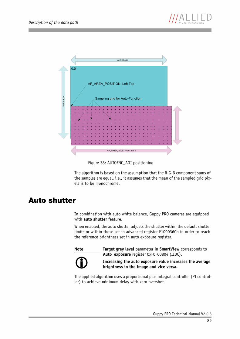
Description of the data path
Guppy PRO Technical Manual V2.0.3
89
The algorithm is based on the assumption that the R-G-B component sums of the samples are equal, i.e., it assumes that the mean of the sampled grid pix-els is to be monochrome.
Auto shutter
In combination with auto white balance, Guppy PRO cameras are equipped with auto shutter feature.
When enabled, the auto shutter adjusts the shutter within the default shutter limits or within those set in advanced register F1000360h in order to reach the reference brightness set in auto exposure register.
The applied algorithm uses a proportional plus integral controller (PI control-ler) to achieve minimum delay with zero overshot.
Figure 38: AUTOFNC_AOI positioning
Note
Target grey level parameter in SmartView corresponds to Auto_exposure register 0xF0F00804 (IIDC).
Increasing the auto exposure value increases the average brightness in the image and vice versa.
AF
_AR
EA
_S
IZE
: Heigh
t: n x 4
AO
I: Y-size
AOI: X-size
AF_AREA_SIZE: Width: n x 4
0,0
AF_AREA_POSITION: Left,Top
Sampling grid for Auto-Function
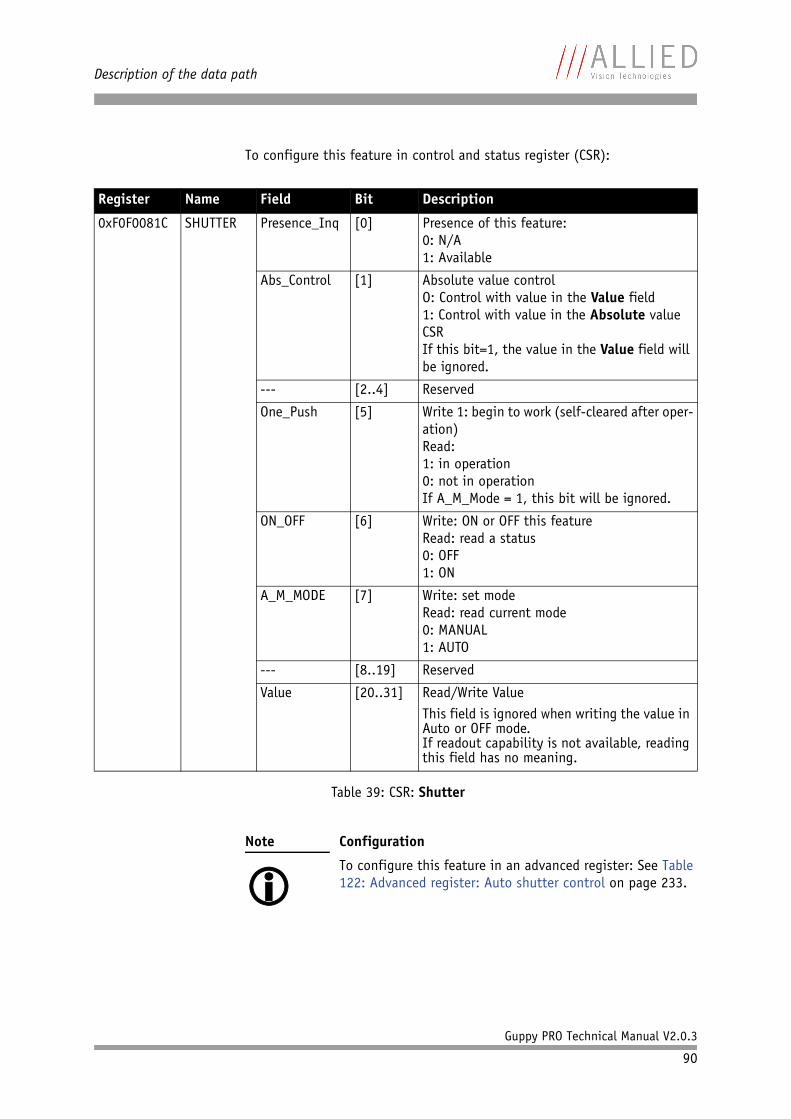
Description of the data path
Guppy PRO Technical Manual V2.0.3
90
To configure this feature in control and status register (CSR):
Register Name Field Bit Description
0xF0F0081C SHUTTER Presence_Inq [0] Presence of this feature:0: N/A1: Available
Abs_Control [1] Absolute value controlO: Control with value in the Value field1: Control with value in the Absolute value CSRIf this bit=1, the value in the Value field will be ignored.
--- [2..4] Reserved
One_Push [5] Write 1: begin to work (self-cleared after oper-ation)Read:1: in operation0: not in operationIf A_M_Mode = 1, this bit will be ignored.
ON_OFF [6] Write: ON or OFF this featureRead: read a status0: OFF1: ON
A_M_MODE [7] Write: set modeRead: read current mode0: MANUAL1: AUTO
--- [8..19] Reserved
Value [20..31] Read/Write ValueThis field is ignored when writing the value in Auto or OFF mode.If readout capability is not available, reading this field has no meaning.
Table 39: CSR: Shutter
Note
Configuration
To configure this feature in an advanced register: See Table 122: Advanced register: Auto shutter control on page 233.
Description of the data path
Guppy PRO Technical Manual V2.0.3
91
Auto gain
All Guppy PRO cameras are equipped with auto gain feature.
When enabled auto gain adjusts the gain within the default gain limits or within the limits set in advanced register F1000370h in order to reach the brightness set in auto exposure register as reference.
Increasing the auto exposure value (aka target grey value) increases the average brightness in the image and vice versa.
The applied algorithm uses a proportional plus integral controller (PI control-ler) to achieve minimum delay with zero overshot.
The following tables show the gain and auto exposure CSR.
Note
Configuration
To configure this feature in an advanced register: See Table 123: Advanced register: Auto gain control on page 234.
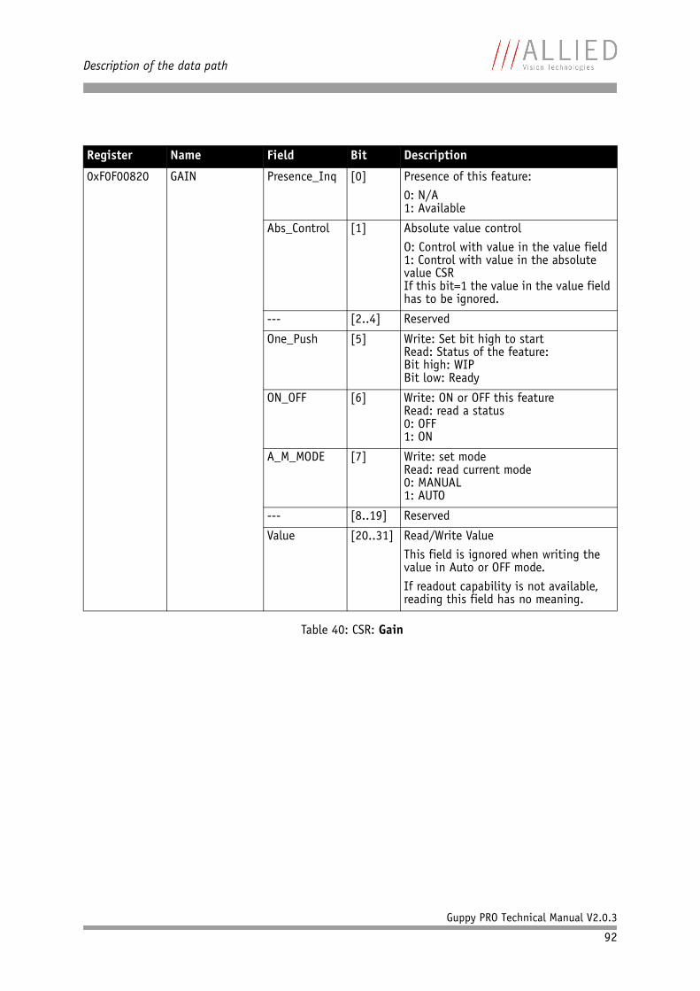
Description of the data path
Guppy PRO Technical Manual V2.0.3
92
Register Name Field Bit Description
0xF0F00820 GAIN Presence_Inq [0] Presence of this feature:0: N/A1: Available
Abs_Control [1] Absolute value controlO: Control with value in the value field1: Control with value in the absolute value CSRIf this bit=1 the value in the value field has to be ignored.
--- [2..4] Reserved
One_Push [5] Write: Set bit high to startRead: Status of the feature:Bit high: WIPBit low: Ready
ON_OFF [6] Write: ON or OFF this featureRead: read a status0: OFF1: ON
A_M_MODE [7] Write: set modeRead: read current mode0: MANUAL1: AUTO
--- [8..19] Reserved
Value [20..31] Read/Write ValueThis field is ignored when writing the value in Auto or OFF mode.If readout capability is not available, reading this field has no meaning.
Table 40: CSR: Gain
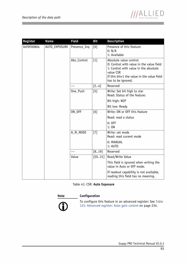
Description of the data path
Guppy PRO Technical Manual V2.0.3
93
Register Name Field Bit Description
0xF0F00804 AUTO_EXPOSURE Presence_Inq [0] Presence of this feature:0: N/A1: Available
Abs_Control [1] Absolute value controlO: Control with value in the value field1: Control with value in the absolute value CSRIf this bit=1 the value in the value field has to be ignored.
--- [2..4] Reserved
One_Push [5] Write: Set bit high to starRead: Status of the feature:
Bit high: WIP
Bit low: Ready
ON_OFF [6] Write: ON or OFF this feature
Read: read a status
0: OFF1: ON
A_M_MODE [7] Write: set modeRead: read current mode
0: MANUAL1: AUTO
--- [8..19] Reserved
Value [20..31] Read/Write Value
This field is ignored when writing the value in Auto or OFF mode.
If readout capability is not available, reading this field has no meaning.
Table 41: CSR: Auto Exposure
Note
Configuration
To configure this feature in an advanced register: See Table 123: Advanced register: Auto gain control on page 234.
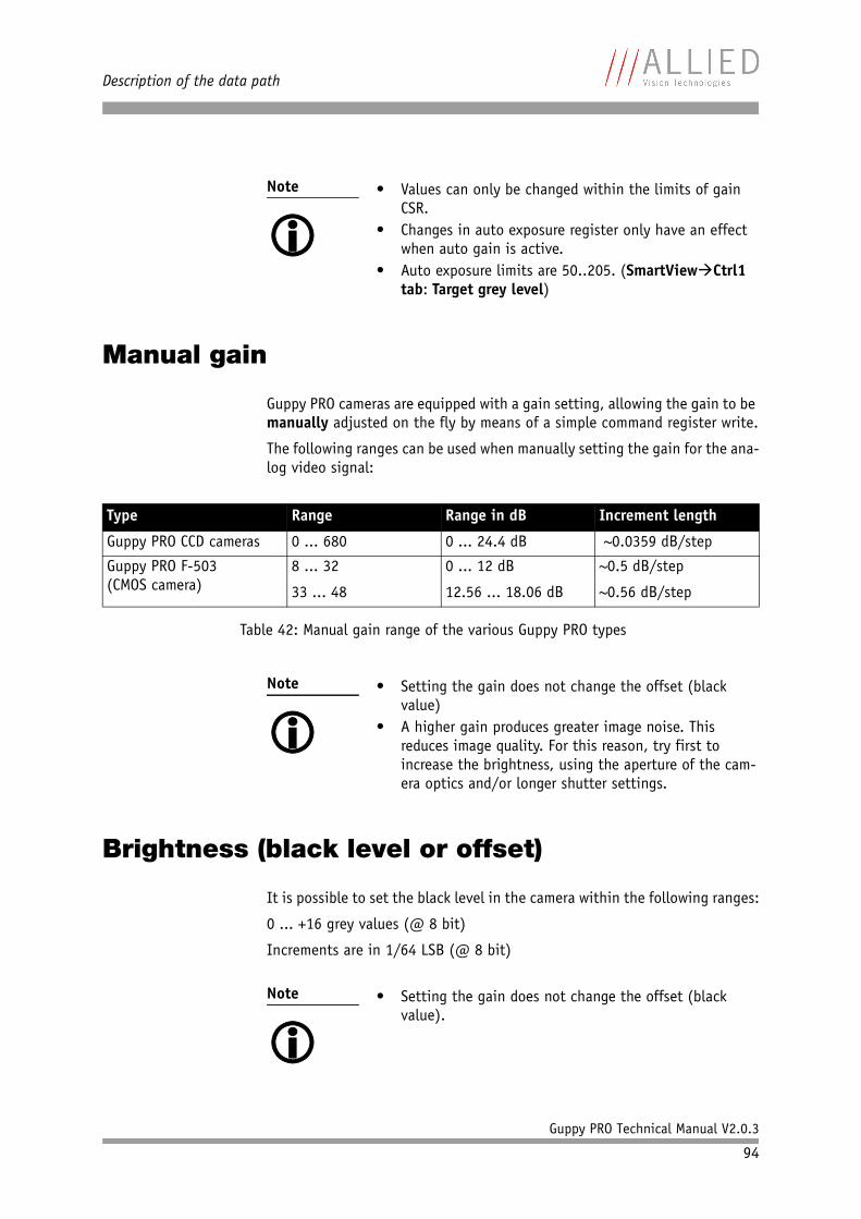
Description of the data path
Guppy PRO Technical Manual V2.0.3
94
Manual gain
Guppy PRO cameras are equipped with a gain setting, allowing the gain to be manually adjusted on the fly by means of a simple command register write.
The following ranges can be used when manually setting the gain for the ana-log video signal:
Brightness (black level or offset)
It is possible to set the black level in the camera within the following ranges:
0 ... +16 grey values (@ 8 bit)
Increments are in 1/64 LSB (@ 8 bit)
Note
• Values can only be changed within the limits of gain
CSR.• Changes in auto exposure register only have an effect
when auto gain is active.• Auto exposure limits are 50..205. (SmartViewCtrl1
tab: Target grey level)
Type Range Range in dB Increment length
Guppy PRO CCD cameras 0 ... 680 0 ... 24.4 dB ~0.0359 dB/step
Guppy PRO F-503(CMOS camera)
8 ... 32
33 ... 48
0 ... 12 dB
12.56 ... 18.06 dB
~0.5 dB/step
~0.56 dB/step
Table 42: Manual gain range of the various Guppy PRO types
Note
• Setting the gain does not change the offset (black
value)• A higher gain produces greater image noise. This
reduces image quality. For this reason, try first to increase the brightness, using the aperture of the cam-era optics and/or longer shutter settings.
Note
• Setting the gain does not change the offset (black
value).
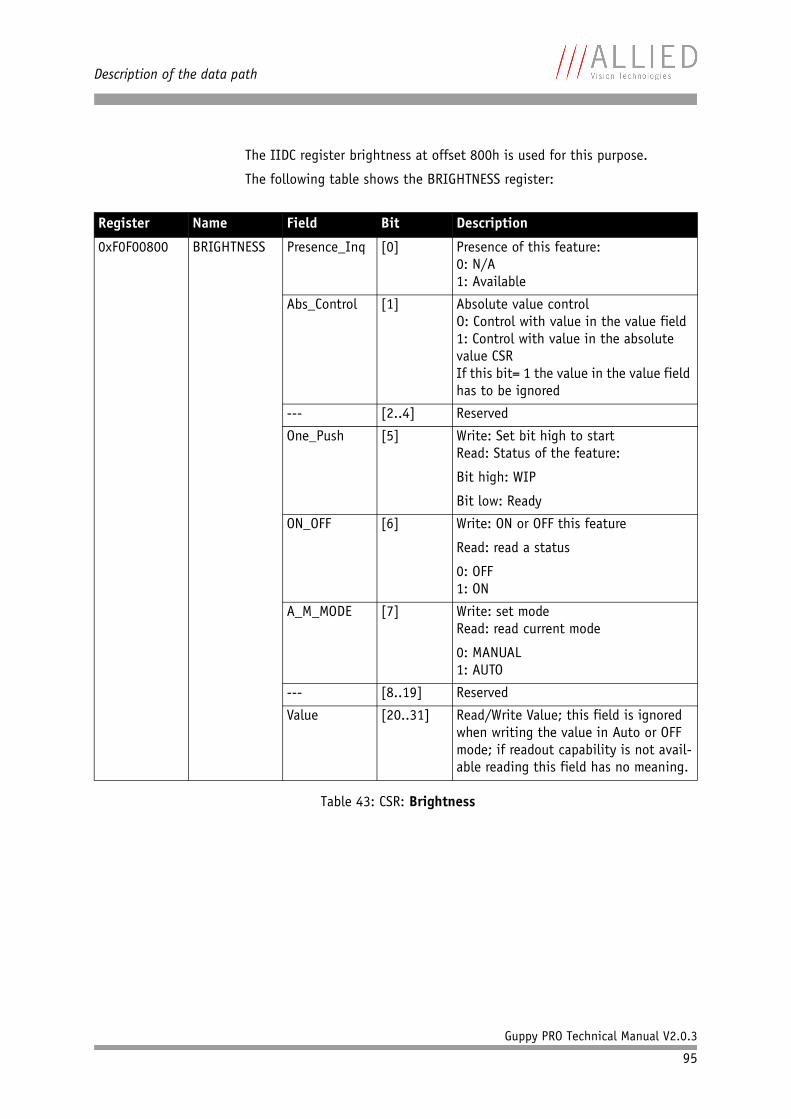
Description of the data path
Guppy PRO Technical Manual V2.0.3
95
The IIDC register brightness at offset 800h is used for this purpose.
The following table shows the BRIGHTNESS register:
Register Name Field Bit Description
0xF0F00800 BRIGHTNESS Presence_Inq [0] Presence of this feature:0: N/A1: Available
Abs_Control [1] Absolute value controlO: Control with value in the value field1: Control with value in the absolute value CSRIf this bit= 1 the value in the value field has to be ignored
--- [2..4] Reserved
One_Push [5] Write: Set bit high to startRead: Status of the feature:
Bit high: WIP
Bit low: Ready
ON_OFF [6] Write: ON or OFF this feature
Read: read a status
0: OFF1: ON
A_M_MODE [7] Write: set modeRead: read current mode
0: MANUAL1: AUTO
--- [8..19] Reserved
Value [20..31] Read/Write Value; this field is ignored when writing the value in Auto or OFF mode; if readout capability is not avail-able reading this field has no meaning.
Table 43: CSR: Brightness
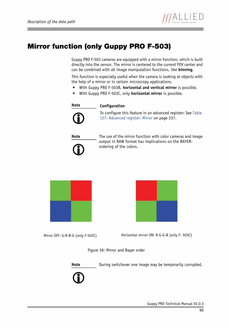
Description of the data path
Guppy PRO Technical Manual V2.0.3
96
Mirror function (only Guppy PRO F-503)
Guppy PRO F-503 cameras are equipped with a mirror function, which is built directly into the sensor. The mirror is centered to the current FOV center and can be combined with all image manipulation functions, like binning.
This function is especially useful when the camera is looking at objects with the help of a mirror or in certain microscopy applications.• With Guppy PRO F-503B, horizontal and vertical mirror is possible.• With Guppy PRO F-503C, only horizontal mirror is possible.
Note
Configuration
To configure this feature in an advanced register: See Table 127: Advanced register: Mirror on page 237.
Note
The use of the mirror function with color cameras and image output in RAW format has implications on the BAYER-ordering of the colors.
Figure 39: Mirror and Bayer order
Note
During switchover one image may be temporarily corrupted.
Horizontal mirror ON: R-G-G-B (only F- 503C)Mirror OFF: G-R-B-G (only F-503C)
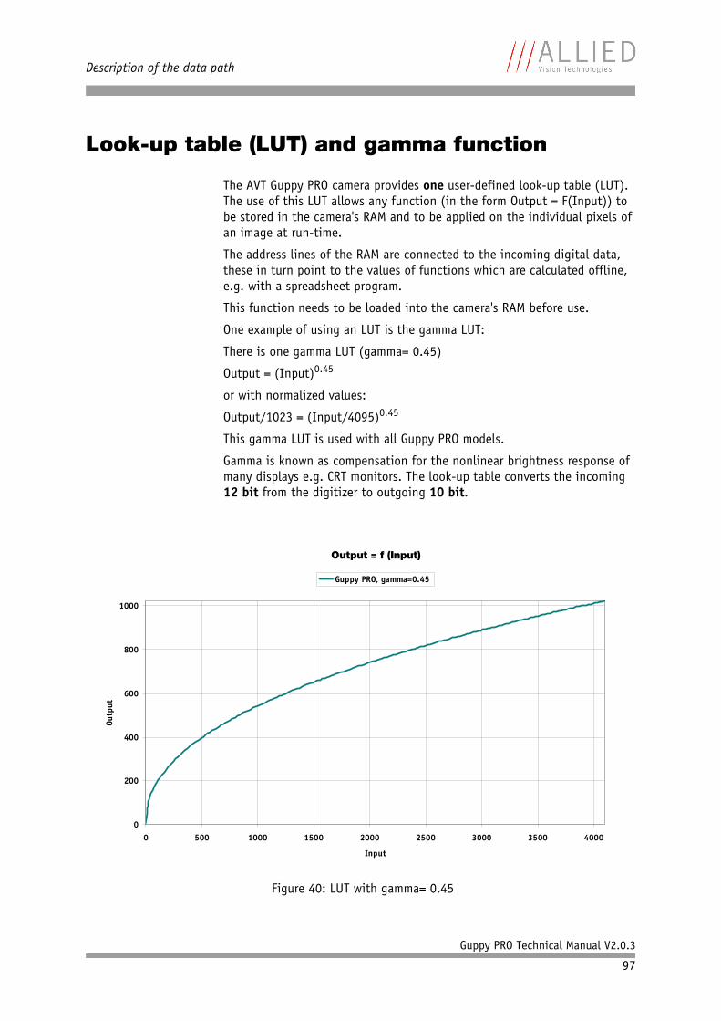
Description of the data path
Guppy PRO Technical Manual V2.0.3
97
Look-up table (LUT) and gamma function
The AVT Guppy PRO camera provides one user-defined look-up table (LUT). The use of this LUT allows any function (in the form Output = F(Input)) to be stored in the camera's RAM and to be applied on the individual pixels of an image at run-time.
The address lines of the RAM are connected to the incoming digital data, these in turn point to the values of functions which are calculated offline, e.g. with a spreadsheet program.
This function needs to be loaded into the camera's RAM before use.
One example of using an LUT is the gamma LUT:
There is one gamma LUT (gamma= 0.45)
Output = (Input)0.45
or with normalized values:
Output/1023 = (Input/4095)0.45
This gamma LUT is used with all Guppy PRO models.
Gamma is known as compensation for the nonlinear brightness response of many displays e.g. CRT monitors. The look-up table converts the incoming 12 bit from the digitizer to outgoing 10 bit.
Figure 40: LUT with gamma= 0.45
Output = f (Input)
0
200
400
600
800
1000
0 500 1000 1500 2000 2500 3000 3500 4000
Input
Outp
ut
Guppy PRO, gamma=0.45
Description of the data path
Guppy PRO Technical Manual V2.0.3
98
Note
• The input value is the most significant 12-bit value
from the digitizer.• Gamma 1 (gamma= 0.45) switches on the LUT. After
overriding the LUT with a user defined content, gamma functionality is no longer available until the next full initialization of the camera.
• LUT content is volatile if you do not use the user pro-files to save the LUT.
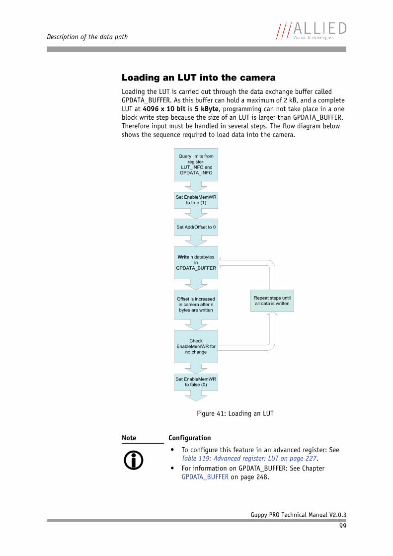
Description of the data path
Guppy PRO Technical Manual V2.0.3
99
Loading an LUT into the cameraLoading the LUT is carried out through the data exchange buffer called GPDATA_BUFFER. As this buffer can hold a maximum of 2 kB, and a complete LUT at 4096 x 10 bit is 5 kByte, programming can not take place in a one block write step because the size of an LUT is larger than GPDATA_BUFFER. Therefore input must be handled in several steps. The flow diagram below shows the sequence required to load data into the camera.
Figure 41: Loading an LUT
Note
Configuration
• To configure this feature in an advanced register: See Table 119: Advanced register: LUT on page 227.
• For information on GPDATA_BUFFER: See Chapter GPDATA_BUFFER on page 248.
Query limits from register:
LUT_INFO and GPDATA_INFO
Set EnableMemWR to true (1)
Set AddrOffset to 0
Write n databytes in
GPDATA_BUFFER
Offset is increased in camera after n bytes are written
Check EnableMemWR for
no change
Repeat steps until all data is written
Set EnableMemWR to false (0)
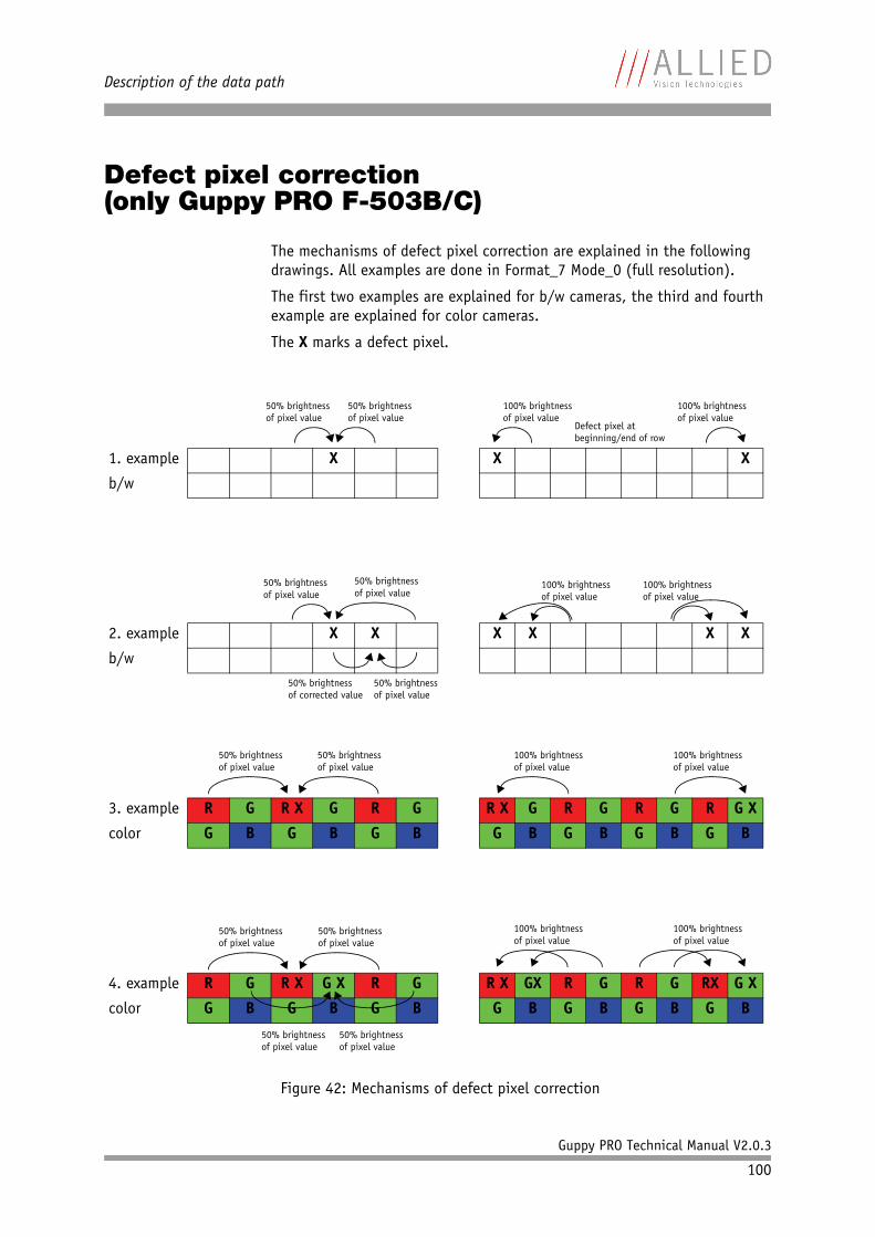
Description of the data path
Guppy PRO Technical Manual V2.0.3
100
Defect pixel correction(only Guppy PRO F-503B/C)
The mechanisms of defect pixel correction are explained in the following drawings. All examples are done in Format_7 Mode_0 (full resolution).
The first two examples are explained for b/w cameras, the third and fourth example are explained for color cameras.
The X marks a defect pixel.
Figure 42: Mechanisms of defect pixel correction
1. example X X X
b/w
2. example X X X X X X
b/w
3. example R G R X G R G R X G R G R G R G X
color G B G B G B G B G B G B G B
4. example R G R X G X R G R X GX R G R G RX G X
color G B G B G B G B G B G B G B
50% brightnessof pixel value
50% brightnessof pixel value
50% brightnessof pixel value
50% brightnessof pixel value
50% brightnessof pixel value
50% brightnessof corrected value
50% brightnessof pixel value
50% brightnessof pixel value
100% brightnessof pixel value
100% brightnessof pixel value
Defect pixel atbeginning/end of row
100% brightnessof pixel value
100% brightnessof pixel value
100% brightnessof pixel value
100% brightnessof pixel value
50% brightnessof pixel value
50% brightnessof pixel value
50% brightnessof pixel value
50% brightnessof pixel value
100% brightnessof pixel value
100% brightnessof pixel value
Description of the data path
Guppy PRO Technical Manual V2.0.3
101
Note
While building defect pixel correction data or uploading them from host, the defect pixel correction data are stored volatile in FPGA.
Optionally you can store the data in a non-volatile memory (Set MemSave to 1).
Note
Configuration
To configure this feature in an advanced register: See Table 120: Advanced register: Defect pixel correction on page 229.
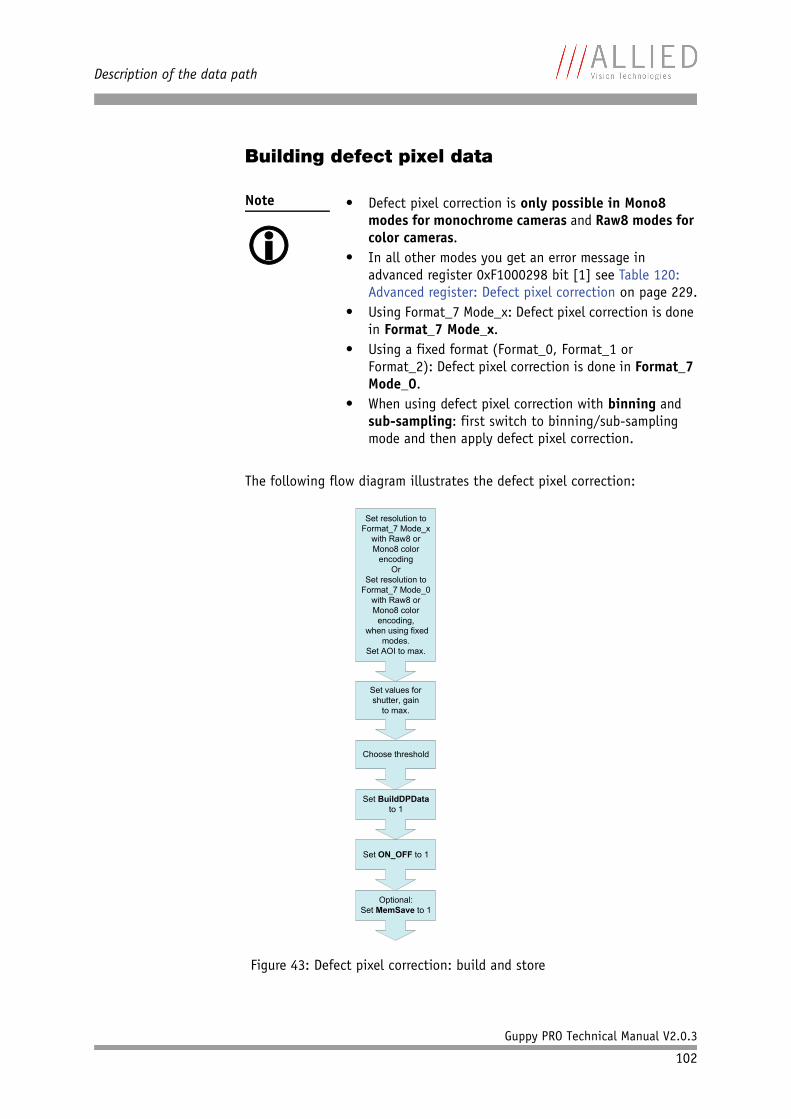
Description of the data path
Guppy PRO Technical Manual V2.0.3
102
Building defect pixel data
The following flow diagram illustrates the defect pixel correction:
Note
• Defect pixel correction is only possible in Mono8
modes for monochrome cameras and Raw8 modes for color cameras.
• In all other modes you get an error message in advanced register 0xF1000298 bit [1] see Table 120: Advanced register: Defect pixel correction on page 229.
• Using Format_7 Mode_x: Defect pixel correction is done in Format_7 Mode_x.
• Using a fixed format (Format_0, Format_1 or Format_2): Defect pixel correction is done in Format_7 Mode_0.
• When using defect pixel correction with binning and sub-sampling: first switch to binning/sub-sampling mode and then apply defect pixel correction.
Figure 43: Defect pixel correction: build and store
Set resolution to Format_7 Mode_x
with Raw8 or Mono8 color
encodingOr
Set resolution to Format_7 Mode_0
with Raw8 or Mono8 color
encoding, when using fixed
modes.Set AOI to max.
Choose threshold
Set BuildDPData to 1
Set ON_OFF to 1
Optional:Set MemSave to 1
Set values for shutter, gain
to max.
Description of the data path
Guppy PRO Technical Manual V2.0.3
103
To build defect pixel data perform the following steps:
Grab an image with defect pixel data
1. Take the camera, remove lens and put on lens cap.
2. Set image resolution to Format_7 Mode_x or Format_7 Mode_0 (when using fixed modes) with Raw8 or Mono8 color encoding, and set AOI to maximum.
3. Set values for shutter and gain to maximum.
4. Grab a single image (one-shot).
Calculate defect pixel coordinates
5. Accept default threshold from system or choose own threshold.
6. Set the BuildDPData flag to 1.
In microcontroller the defect pixel calculation is started. The detected defect pixel coordinates are stored.
Defect pixel coordinates are:– 16-bit y-coordinate and– 16-bit x-coordinate
DPC data are organized like this:
The calculated mean value is written in advanced register Mean field (0xF1000298 bit [18..24]).
The number of defect pixels is written in advanced register DPDataSize (0xF100029C bit [4..17]). Due to 16-bit format: to get the number of defect pixels read out this value and divide through 4. For more infor-mation see Table 120: Advanced register: Defect pixel correction on page 229f.
Reset values (resolution, shutter, gain, brightness)
7. Take the camera, remove lens cap and thread the lens onto the camera.
8. Reset values for image resolution, shutter, gain and brightness (offset) to their previous values.
Note
A mean value is calculated over the entire image that was grabbed previously.
Definition: A defect pixel is every pixel value of this previously grabbed image that is:
• greater than (mean value + threshold)or• less than (mean value - threshold)
31 16 15 0
y-coordinate x-coordinate
Description of the data path
Guppy PRO Technical Manual V2.0.3
104
9. Grab a single image (one-shot).
Activate/deactivate defect pixel correctionActivate:
1. Set ON_OFF flag to 1.
Deactivate:
1. Set ON_OFF flag to 0.
Store defect pixel data non-volatile1. Set the MemSave flag to 1.
Load non-volatile stored defect pixel data1. Set the MemLoad flag to 1.
All non-volatile stored defect pixel coordinates are loaded.
Send defect pixel data to the host1. Set EnaMemRD flag to 1.
Defect pixel data is transferred from dual port RAM to host.
2. Read DPDataSize.
This is the current defect pixel count from the camera.
Receive defect pixel data from the host1. Set EnaMemWR flag to 1.
Note
• Switch off camera and switch on again: defect pixel data will get lost
• Initialize camera (start-up or soft reset): non-volatile stored defect pixel data are loaded automatically
Description of the data path
Guppy PRO Technical Manual V2.0.3
105
Binning (only b/w cameras; F-503: also color cameras)
2 x binning (F-503 also 4 x)Definition Binning is the process of combining neighboring pixels while being read out
from the sensor.
Binning is used primarily for 3 reasons:• a reduction in the number of pixels and thus the amount of data while
retaining the original image area angle• an increase in the frame rate (CCD models: vertical binning only; CMOS
models: also horizontal binning)• a brighter image, also resulting in an improvement in the signal-to-
noise ratio of the image
Signal-to-noise ratio (SNR) and signal-to-noise separation specify the quality of a signal with regard to its reproduction of intensities. The value signifies how high the ratio of noise is in regard to the maximum achievable signal intensity.
The higher this value, the better the signal quality. The unit of measurement used is generally known as the decibel (dB), a logarithmic power level. 6 dB is the signal level at approximately a factor of 2.
However, the advantages of increasing signal quality are accompanied by a reduction in resolution.
Only Format_7 Binning is possible only in video Format_7. The type of binning used depends on the video mode.
Types In general, we distinguish between the following types of binning(H=horizontal, V=vertical):• 2 x H-binning• 2 x V-binning• 4 x H-binning (only F-503)• 4 x V-binning (only F-503)
and the full binning modes:• 2 x full binning (a combination of 2 x H-binning and 2 x V-binning)• 4 x full binning (a combination of 4 x H-binning and 4 x V-binning)
(only F-503)
Note
• Binning does not change offset, brightness or black-
level.
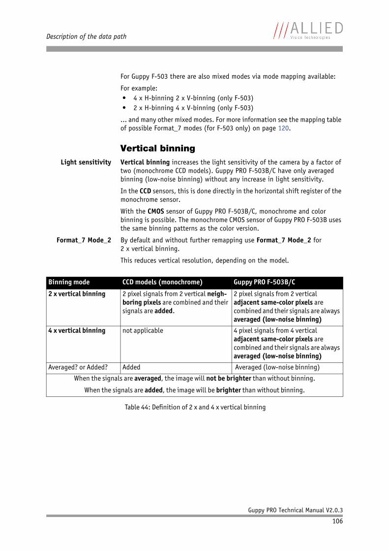
Description of the data path
Guppy PRO Technical Manual V2.0.3
106
For Guppy F-503 there are also mixed modes via mode mapping available:
For example:• 4 x H-binning 2 x V-binning (only F-503)• 2 x H-binning 4 x V-binning (only F-503)
... and many other mixed modes. For more information see the mapping table of possible Format_7 modes (for F-503 only) on page 120.
Vertical binningLight sensitivity Vertical binning increases the light sensitivity of the camera by a factor of
two (monochrome CCD models). Guppy PRO F-503B/C have only averaged binning (low-noise binning) without any increase in light sensitivity.
In the CCD sensors, this is done directly in the horizontal shift register of the monochrome sensor.
With the CMOS sensor of Guppy PRO F-503B/C, monochrome and color binning is possible. The monochrome CMOS sensor of Guppy PRO F-503B uses the same binning patterns as the color version.
Format_7 Mode_2 By default and without further remapping use Format_7 Mode_2 for2 x vertical binning.
This reduces vertical resolution, depending on the model.
Binning mode CCD models (monochrome) Guppy PRO F-503B/C
2 x vertical binning 2 pixel signals from 2 vertical neigh-boring pixels are combined and their signals are added.
2 pixel signals from 2 vertical adjacent same-color pixels are combined and their signals are always averaged (low-noise binning)
4 x vertical binning not applicable 4 pixel signals from 4 vertical adjacent same-color pixels are combined and their signals are always averaged (low-noise binning)
Averaged? or Added? Added Averaged (low-noise binning)
When the signals are averaged, the image will not be brighter than without binning.
When the signals are added, the image will be brighter than without binning.
Table 44: Definition of 2 x and 4 x vertical binning
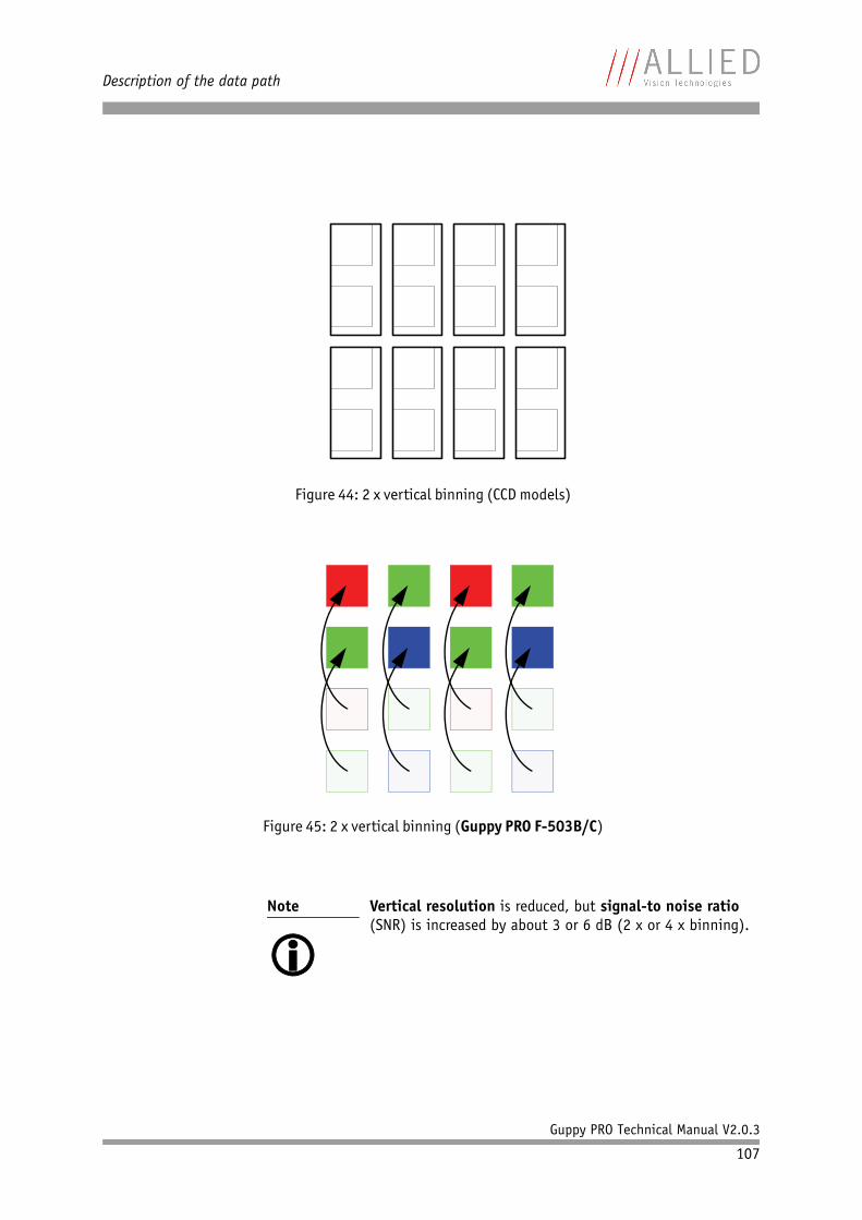
Description of the data path
Guppy PRO Technical Manual V2.0.3
107
Figure 44: 2 x vertical binning (CCD models)
Figure 45: 2 x vertical binning (Guppy PRO F-503B/C)
Note
Vertical resolution is reduced, but signal-to noise ratio (SNR) is increased by about 3 or 6 dB (2 x or 4 x binning).

Description of the data path
Guppy PRO Technical Manual V2.0.3
108
Note
The image appears vertically compressed in this mode and no longer exhibits a true aspect ratio.
If vertical binning is activated the image may appear to be over-exposed and may require correction.
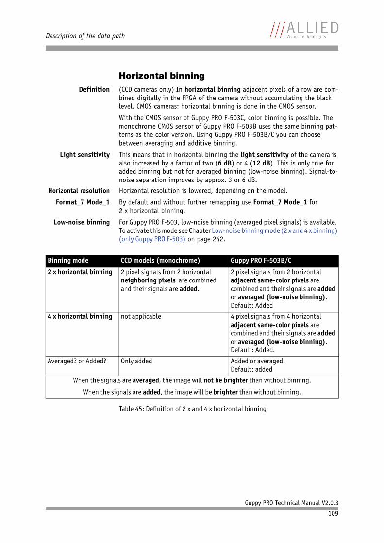
Description of the data path
Guppy PRO Technical Manual V2.0.3
109
Horizontal binningDefinition (CCD cameras only) In horizontal binning adjacent pixels of a row are com-
bined digitally in the FPGA of the camera without accumulating the black level. CMOS cameras: horizontal binning is done in the CMOS sensor.
With the CMOS sensor of Guppy PRO F-503C, color binning is possible. The monochrome CMOS sensor of Guppy PRO F-503B uses the same binning pat-terns as the color version. Using Guppy PRO F-503B/C you can choose between averaging and additive binning.
Light sensitivity This means that in horizontal binning the light sensitivity of the camera is also increased by a factor of two (6 dB) or 4 (12 dB). This is only true for added binning but not for averaged binning (low-noise binning). Signal-to-noise separation improves by approx. 3 or 6 dB.
Horizontal resolution Horizontal resolution is lowered, depending on the model.
Format_7 Mode_1 By default and without further remapping use Format_7 Mode_1 for2 x horizontal binning.
Low-noise binning For Guppy PRO F-503, low-noise binning (averaged pixel signals) is available. To activate this mode see Chapter Low-noise binning mode (2 x and 4 x binning) (only Guppy PRO F-503) on page 242.
Binning mode CCD models (monochrome) Guppy PRO F-503B/C
2 x horizontal binning 2 pixel signals from 2 horizontal neighboring pixels are combined and their signals are added.
2 pixel signals from 2 horizontal adjacent same-color pixels are combined and their signals are added or averaged (low-noise binning).Default: Added
4 x horizontal binning not applicable 4 pixel signals from 4 horizontal adjacent same-color pixels are combined and their signals are added or averaged (low-noise binning).Default: Added.
Averaged? or Added? Only added Added or averaged.Default: added
When the signals are averaged, the image will not be brighter than without binning.
When the signals are added, the image will be brighter than without binning.
Table 45: Definition of 2 x and 4 x horizontal binning
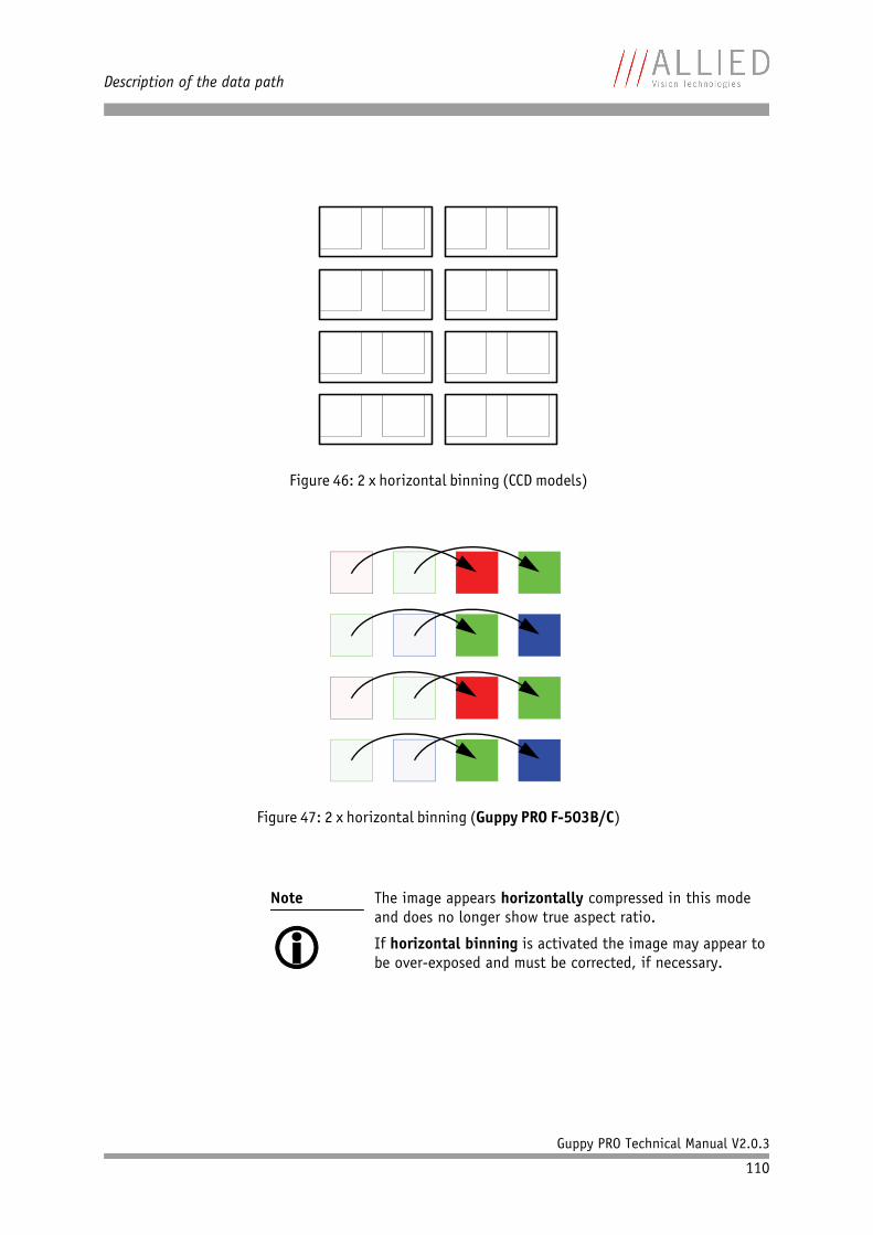
Description of the data path
Guppy PRO Technical Manual V2.0.3
110
Figure 46: 2 x horizontal binning (CCD models)
Figure 47: 2 x horizontal binning (Guppy PRO F-503B/C)
Note
The image appears horizontally compressed in this mode and does no longer show true aspect ratio.
If horizontal binning is activated the image may appear to be over-exposed and must be corrected, if necessary.
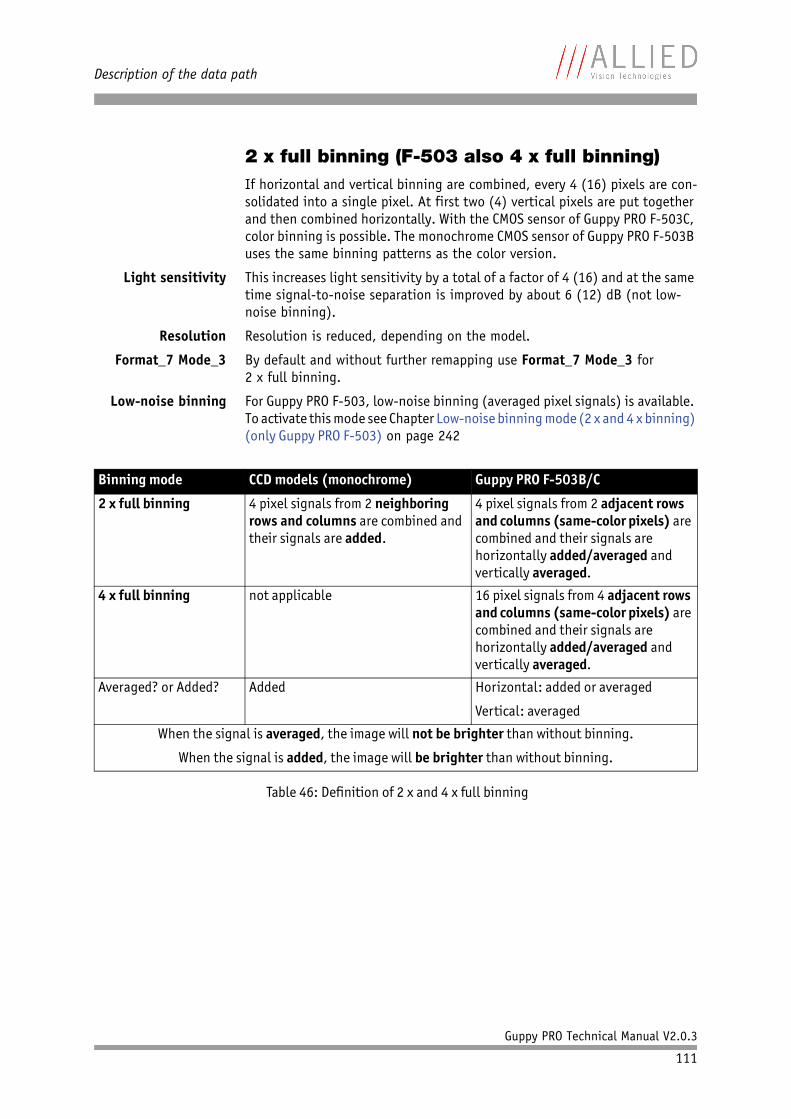
Description of the data path
Guppy PRO Technical Manual V2.0.3
111
2 x full binning (F-503 also 4 x full binning)If horizontal and vertical binning are combined, every 4 (16) pixels are con-solidated into a single pixel. At first two (4) vertical pixels are put together and then combined horizontally. With the CMOS sensor of Guppy PRO F-503C, color binning is possible. The monochrome CMOS sensor of Guppy PRO F-503B uses the same binning patterns as the color version.
Light sensitivity This increases light sensitivity by a total of a factor of 4 (16) and at the same time signal-to-noise separation is improved by about 6 (12) dB (not low-noise binning).
Resolution Resolution is reduced, depending on the model.
Format_7 Mode_3 By default and without further remapping use Format_7 Mode_3 for2 x full binning.
Low-noise binning For Guppy PRO F-503, low-noise binning (averaged pixel signals) is available. To activate this mode see Chapter Low-noise binning mode (2 x and 4 x binning) (only Guppy PRO F-503) on page 242
Binning mode CCD models (monochrome) Guppy PRO F-503B/C
2 x full binning 4 pixel signals from 2 neighboring rows and columns are combined and their signals are added.
4 pixel signals from 2 adjacent rows and columns (same-color pixels) are combined and their signals are horizontally added/averaged and vertically averaged.
4 x full binning not applicable 16 pixel signals from 4 adjacent rows and columns (same-color pixels) are combined and their signals are horizontally added/averaged and vertically averaged.
Averaged? or Added? Added Horizontal: added or averaged
Vertical: averaged
When the signal is averaged, the image will not be brighter than without binning.
When the signal is added, the image will be brighter than without binning.
Table 46: Definition of 2 x and 4 x full binning
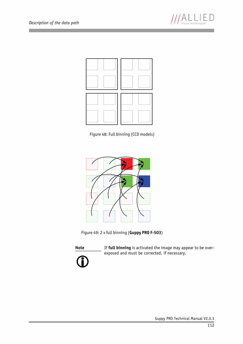
Description of the data path
Guppy PRO Technical Manual V2.0.3
112
Figure 48: Full binning (CCD models)
Figure 49: 2 x full binning (Guppy PRO F-503)
Note
If full binning is activated the image may appear to be over-exposed and must be corrected, if necessary.
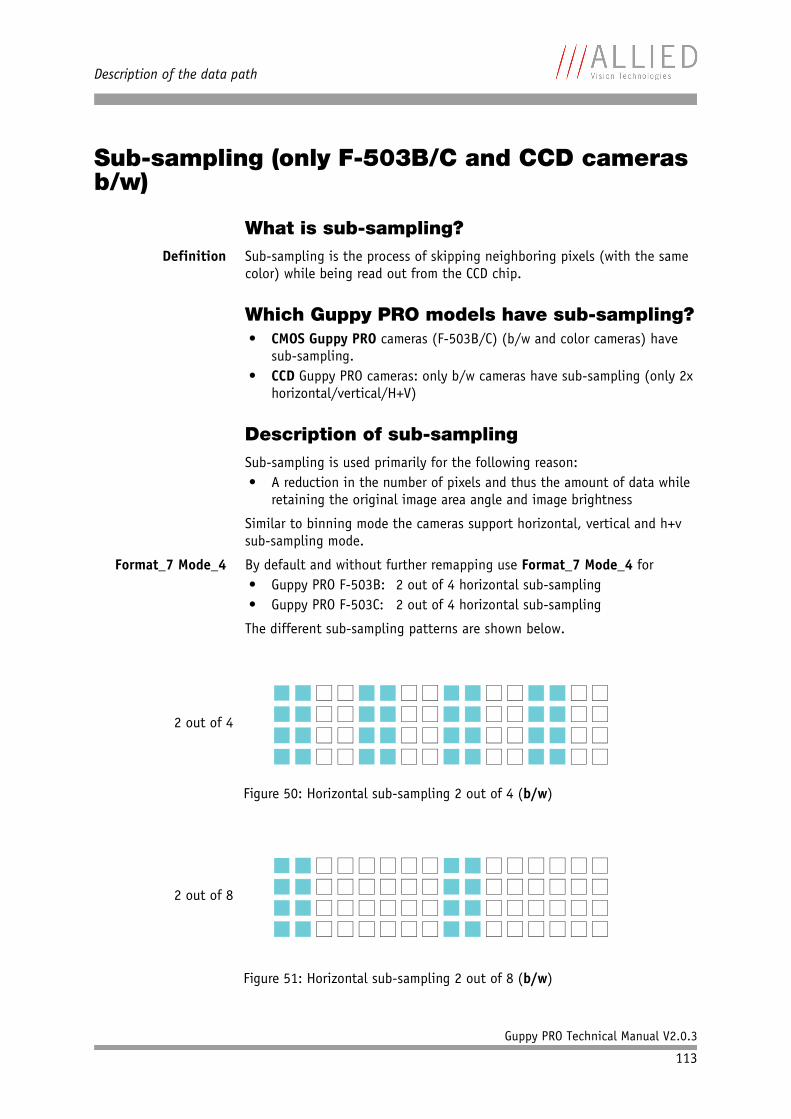
Description of the data path
Guppy PRO Technical Manual V2.0.3
113
Sub-sampling (only F-503B/C and CCD cameras b/w)
What is sub-sampling?Definition Sub-sampling is the process of skipping neighboring pixels (with the same
color) while being read out from the CCD chip.
Which Guppy PRO models have sub-sampling?• CMOS Guppy PRO cameras (F-503B/C) (b/w and color cameras) have
sub-sampling.• CCD Guppy PRO cameras: only b/w cameras have sub-sampling (only 2x
horizontal/vertical/H+V)
Description of sub-samplingSub-sampling is used primarily for the following reason:• A reduction in the number of pixels and thus the amount of data while
retaining the original image area angle and image brightness
Similar to binning mode the cameras support horizontal, vertical and h+v sub-sampling mode.
Format_7 Mode_4 By default and without further remapping use Format_7 Mode_4 for• Guppy PRO F-503B: 2 out of 4 horizontal sub-sampling• Guppy PRO F-503C: 2 out of 4 horizontal sub-sampling
The different sub-sampling patterns are shown below.
Figure 50: Horizontal sub-sampling 2 out of 4 (b/w)
Figure 51: Horizontal sub-sampling 2 out of 8 (b/w)
2 out of 4
2 out of 8
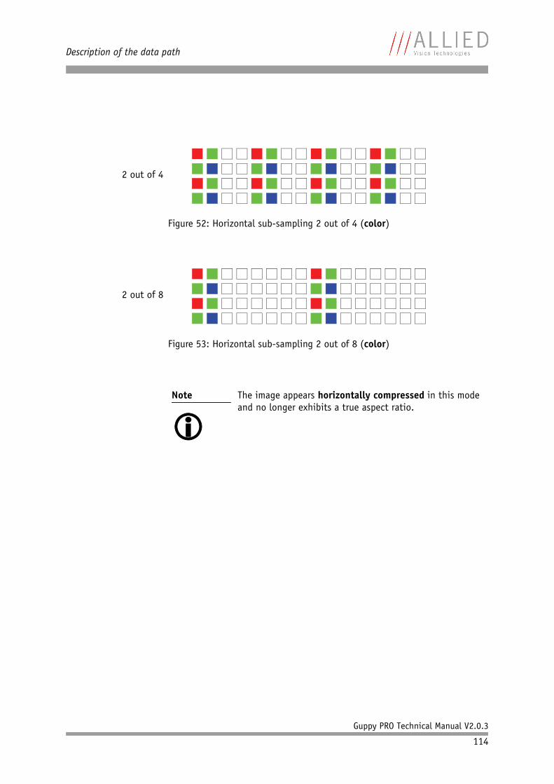
Description of the data path
Guppy PRO Technical Manual V2.0.3
114
Figure 52: Horizontal sub-sampling 2 out of 4 (color)
Figure 53: Horizontal sub-sampling 2 out of 8 (color)
Note
The image appears horizontally compressed in this mode and no longer exhibits a true aspect ratio.
2 out of 4
2 out of 8
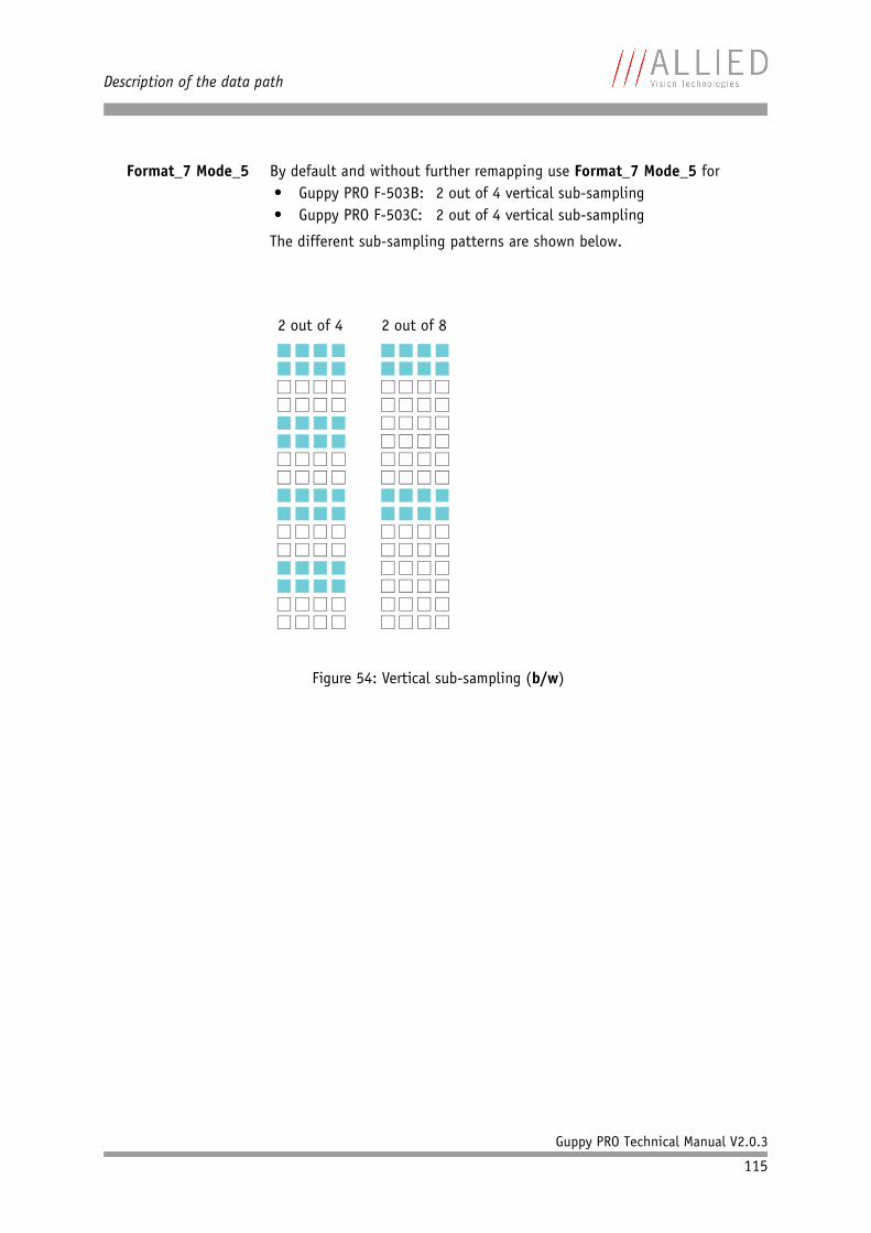
Description of the data path
Guppy PRO Technical Manual V2.0.3
115
Format_7 Mode_5 By default and without further remapping use Format_7 Mode_5 for• Guppy PRO F-503B: 2 out of 4 vertical sub-sampling• Guppy PRO F-503C: 2 out of 4 vertical sub-sampling
The different sub-sampling patterns are shown below.
Figure 54: Vertical sub-sampling (b/w)
2 out of 4 2 out of 8
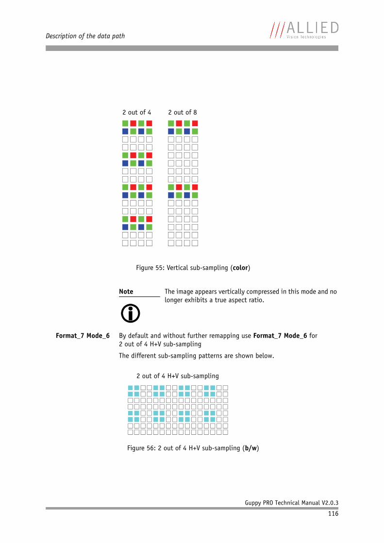
Description of the data path
Guppy PRO Technical Manual V2.0.3
116
Format_7 Mode_6 By default and without further remapping use Format_7 Mode_6 for2 out of 4 H+V sub-sampling
The different sub-sampling patterns are shown below.
Figure 55: Vertical sub-sampling (color)
Note
The image appears vertically compressed in this mode and no longer exhibits a true aspect ratio.
Figure 56: 2 out of 4 H+V sub-sampling (b/w)
2 out of 4 2 out of 8
2 out of 4 H+V sub-sampling
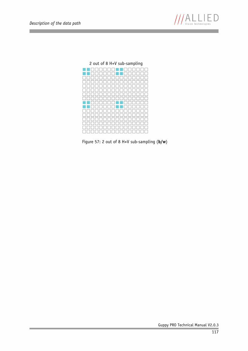
Description of the data path
Guppy PRO Technical Manual V2.0.3
117
Figure 57: 2 out of 8 H+V sub-sampling (b/w)
2 out of 8 H+V sub-sampling
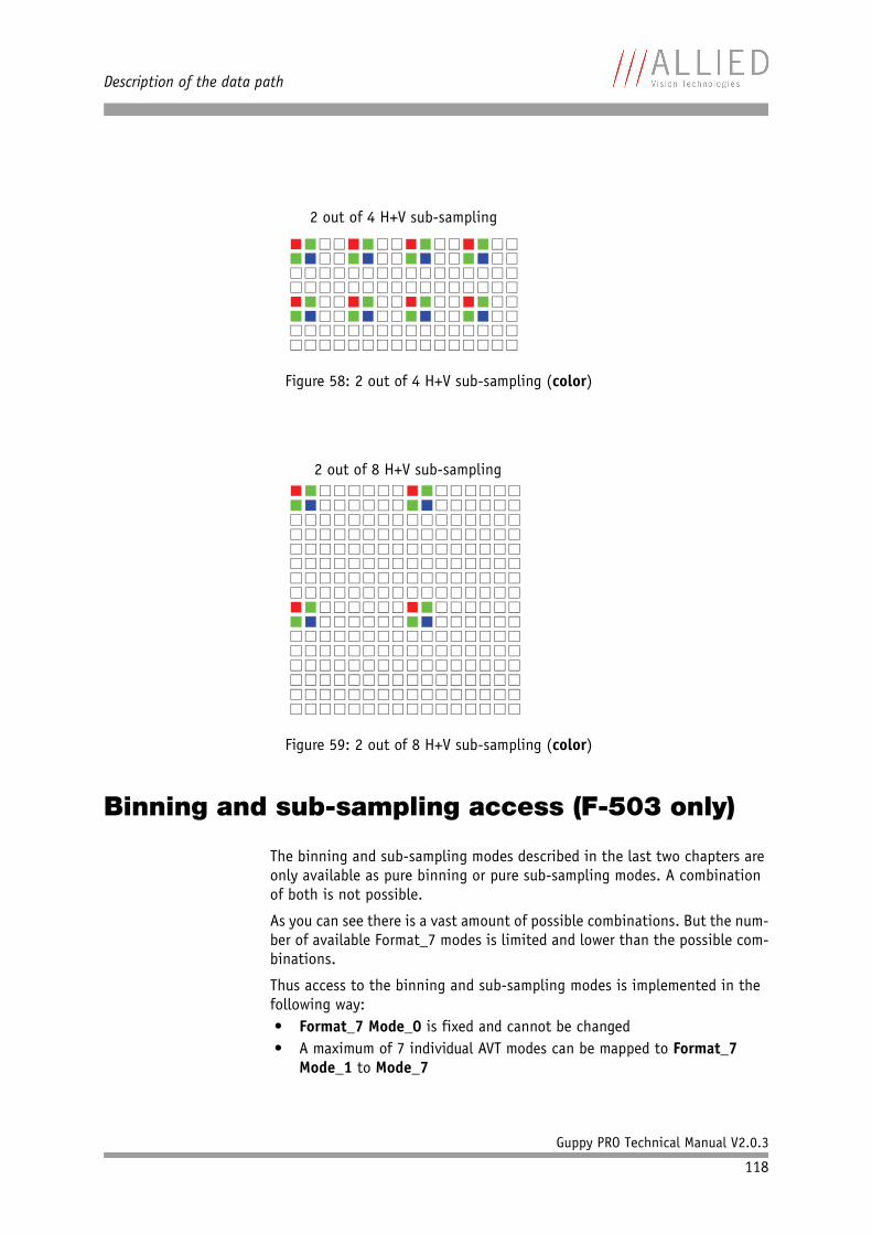
Description of the data path
Guppy PRO Technical Manual V2.0.3
118
Binning and sub-sampling access (F-503 only)
The binning and sub-sampling modes described in the last two chapters are only available as pure binning or pure sub-sampling modes. A combination of both is not possible.
As you can see there is a vast amount of possible combinations. But the num-ber of available Format_7 modes is limited and lower than the possible com-binations.
Thus access to the binning and sub-sampling modes is implemented in the following way:• Format_7 Mode_0 is fixed and cannot be changed• A maximum of 7 individual AVT modes can be mapped to Format_7
Mode_1 to Mode_7
Figure 58: 2 out of 4 H+V sub-sampling (color)
Figure 59: 2 out of 8 H+V sub-sampling (color)
2 out of 4 H+V sub-sampling
2 out of 8 H+V sub-sampling
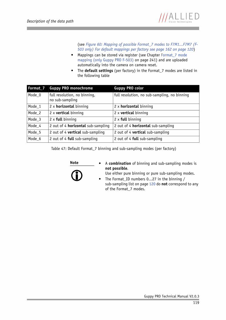
Description of the data path
Guppy PRO Technical Manual V2.0.3
119
(see Figure 60: Mapping of possible Format_7 modes to F7M1...F7M7 (F-503 only) For default mappings per factory see page 162 on page 120)
• Mappings can be stored via register (see Chapter Format_7 mode mapping (only Guppy PRO F-503) on page 241) and are uploaded automatically into the camera on camera reset.
• The default settings (per factory) in the Format_7 modes are listed in the following table
Format_7 Guppy PRO monochrome Guppy PRO color
Mode_0 full resolution, no binning,no sub-sampling
full resolution, no sub-sampling, no binning
Mode_1 2 x horizontal binning 2 x horizontal binning
Mode_2 2 x vertical binning 2 x vertical binning
Mode_3 2 x full binning 2 x full binning
Mode_4 2 out of 4 horizontal sub-sampling 2 out of 4 horizontal sub-sampling
Mode_5 2 out of 4 vertical sub-sampling 2 out of 4 vertical sub-sampling
Mode_6 2 out of 4 full sub-sampling 2 out of 4 full sub-sampling
Table 47: Default Format_7 binning and sub-sampling modes (per factory)
Note
• A combination of binning and sub-sampling modes is
not possible.Use either pure binning or pure sub-sampling modes.
• The Format_ID numbers 0...27 in the binning / sub-sampling list on page 120 do not correspond to any of the Format_7 modes.
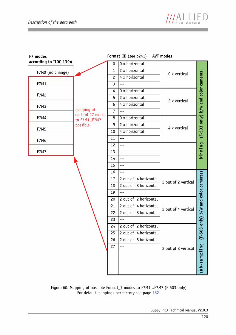
Description of the data path
Guppy PRO Technical Manual V2.0.3
120
Figure 60: Mapping of possible Format_7 modes to F7M1...F7M7 (F-503 only)For default mappings per factory see page 162
F7M0 (no change)
F7M6
F7M5
F7M4
F7M3
F7M2
F7M1
F7M7
Format_ID (see p241) AVT modes
0 0 x horizontal
0 x vertical
bin
nin
g (F
-503
onl
y) b
/w a
nd c
olor
cam
eras
1 2 x horizontal
2 4 x horizontal
3 ---
4 0 x horizontal
2 x vertical5 2 x horizontal
6 4 x horizontal
7 ---
8 0 x horizontal
4 x vertical9 2 x horizontal
10 4 x horizontal
11 ---
12 ---
13 ---
14 ---
15 ---
16 ---
2 out of 2 vertical
sub
-sam
pli
ng
(F-5
03 o
nly)
b/w
and
col
or c
amer
ass
17 2 out of 4 horizontal
18 2 out of 8 horizontal
19 ---
20 2 out of 2 horizontal
2 out of 4 vertical21 2 out of 4 horizontal
22 2 out of 8 horizontal
23 ---
24 2 out of 2 horizontal
2 out of 8 vertical
25 2 out of 4 horizontal
26 2 out of 8 horizontal
27 ---
F7 modes
mapping ofeach of 27 modesto F7M1..F7M7possible
according to IIDC 1394
Description of the data path
Guppy PRO Technical Manual V2.0.3
121
Packed 12-Bit Mode
All Guppy PRO cameras have the so-called Packed 12-Bit Mode. This means: two 12-bit pixel values are packed into 3 bytes instead of 4 bytes.
The color codings are implemented via Vendor Unique Color_Coding accord-ing to IIDC V1.31: COLOR_CODING_INQ @ 024h...033h, IDs=128-255)
See Table 108: Format_7 control and status register on page 213.
Note
Configuration
To configure this feature in an advanced register: See Table 131: Advanced register: Format_7 mode mapping on page 241.
B/w cameras Color cameras
Packed 12-Bit MONO camera mode
SmartView: MONO12
Packed 12-Bit RAW camera mode
SmartView: RAW12
Mono and raw mode have the same implementation.
Table 48: Packed 12-Bit Mode
Note
For data block packet format see Table 35: Packed 12-Bit Mode (mono and raw) Y12 format (AVT) on page 79.
For data structure see Table 36: Data structure of Packed 12-Bit Mode (mono and raw) (AVT) on page 81.
Mode Color_Coding ID
Packed 12-Bit MONO ECCID_MONO12 ID=132
Packed 12-Bit RAW ECCID_RAW12 ID=136
Table 49: Packed 12-Bit Mode: color coding
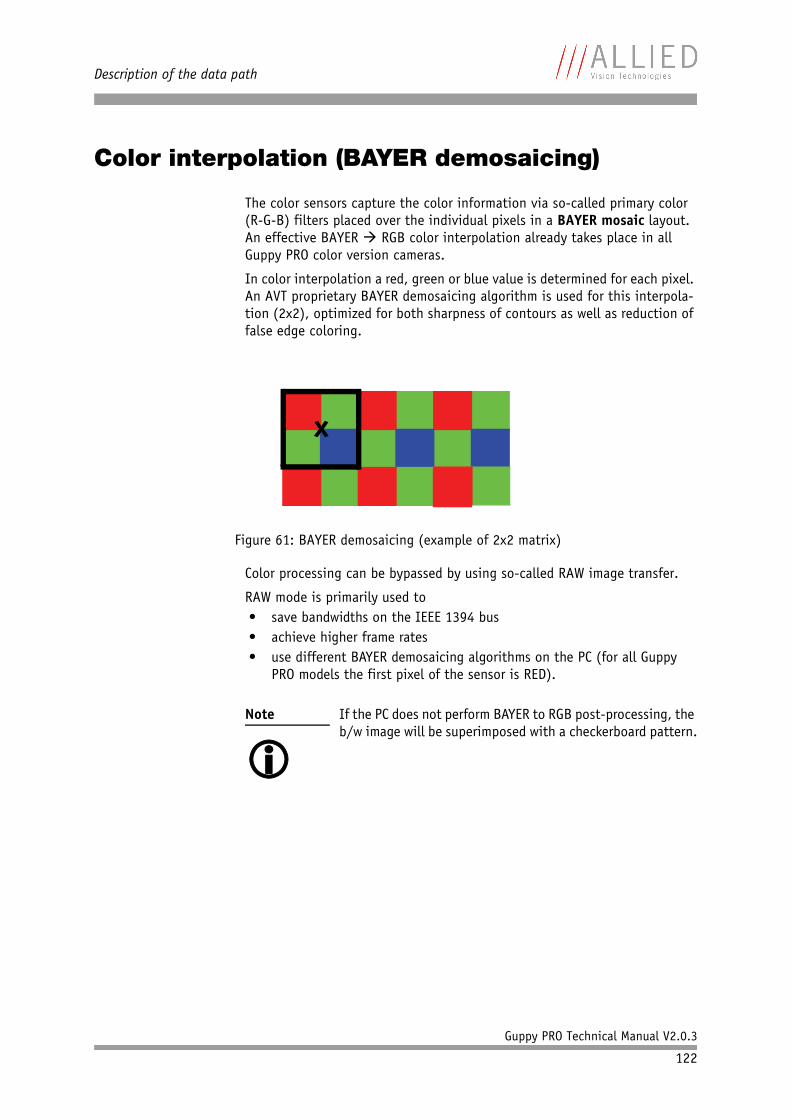
Description of the data path
Guppy PRO Technical Manual V2.0.3
122
Color interpolation (BAYER demosaicing)
The color sensors capture the color information via so-called primary color (R-G-B) filters placed over the individual pixels in a BAYER mosaic layout. An effective BAYER RGB color interpolation already takes place in all Guppy PRO color version cameras.
In color interpolation a red, green or blue value is determined for each pixel. An AVT proprietary BAYER demosaicing algorithm is used for this interpola-tion (2x2), optimized for both sharpness of contours as well as reduction of false edge coloring.
Color processing can be bypassed by using so-called RAW image transfer.
RAW mode is primarily used to• save bandwidths on the IEEE 1394 bus• achieve higher frame rates• use different BAYER demosaicing algorithms on the PC (for all Guppy
PRO models the first pixel of the sensor is RED).
Figure 61: BAYER demosaicing (example of 2x2 matrix)
Note
If the PC does not perform BAYER to RGB post-processing, the b/w image will be superimposed with a checkerboard pattern.
x
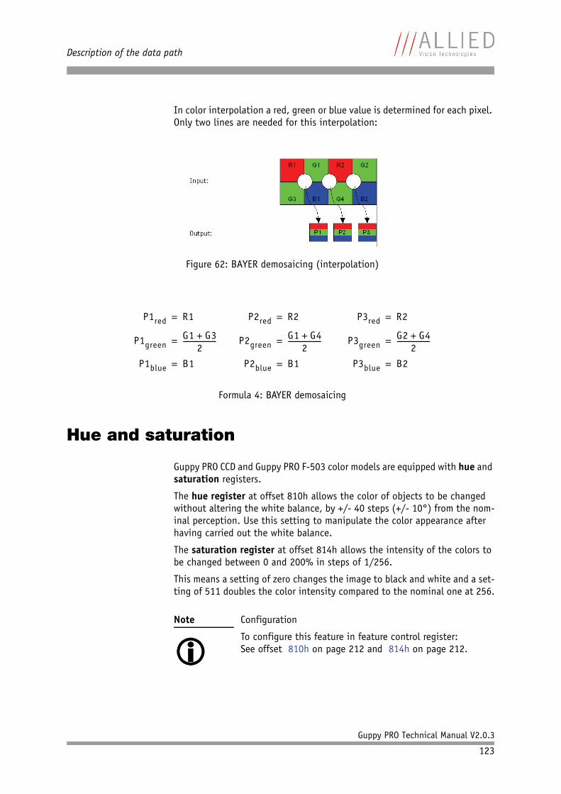
Description of the data path
Guppy PRO Technical Manual V2.0.3
123
In color interpolation a red, green or blue value is determined for each pixel. Only two lines are needed for this interpolation:
Hue and saturation
Guppy PRO CCD and Guppy PRO F-503 color models are equipped with hue and saturation registers.
The hue register at offset 810h allows the color of objects to be changed without altering the white balance, by +/- 40 steps (+/- 10°) from the nom-inal perception. Use this setting to manipulate the color appearance after having carried out the white balance.
The saturation register at offset 814h allows the intensity of the colors to be changed between 0 and 200% in steps of 1/256.
This means a setting of zero changes the image to black and white and a set-ting of 511 doubles the color intensity compared to the nominal one at 256.
Figure 62: BAYER demosaicing (interpolation)
Formula 4: BAYER demosaicing
Note
Configuration
To configure this feature in feature control register:See offset 810h on page 212 and 814h on page 212.
P1red R1=
P1greenG1 G3+
2-------------------=
P1blue B1=
P2red R2=
P2greenG1 G4+
2-------------------=
P2blue B1=
P3red R2=
P3greenG2 G4+
2-------------------=
P3blue B2=
Description of the data path
Guppy PRO Technical Manual V2.0.3
124
Color correction
Why color correction?
The spectral response of a CCD is different of those of an output device or the human eye. This is the reason for the fact that perfect color reproduction is not possible. In each Guppy PRO camera there is a factory setting for the color correction coefficients, see Chapter GretagMacbeth ColorChecker on page 124.
Color correction is needed to eliminate the overlap in the color channels. This overlap is caused by the fact that:• Blue light: is seen by the red and green pixels on the CCD• Red light: is seen by the blue and green pixels on the CCD• Green light: is seen by the red and blue pixels on the CCD
The color correction matrix subtracts out this overlap.
Color correction in AVT cameras
In AVT cameras the color correction is realized as an additional step in the process from the sensor data to color output.
Color correction is used to harmonize colors for the human eye.
Guppy PRO cameras have the so-called color correction matrix. This means: you are able to manipulate the color-correction coefficients yourself.
Color correction: formula
Before converting to the YUV format, color correction on all color models is carried out after BAYER demosaicing via a matrix as follows:
GretagMacbeth ColorChecker
Sensor-specific coefficients Cxy are scientifically generated to ensure that GretagMacbeth™ ColorChecker® colors are displayed with highest color fidel-ity and color balance.
Note
Configuration
Hue and saturation do not show any effect on Guppy PRO color models in the Raw8 and Raw16 format, because color processing is switched off in all Raw formats.
Formula 5: Color correction
red* Crr red Cgr green Cbr blue+ +=
green* Crg red Cgg green Cbg blue+ +=
blue* Crb red Cgb green Cbb blue+ +=
Description of the data path
Guppy PRO Technical Manual V2.0.3
125
These coefficients are stored in user set 0 and can not be overwritten (factory setting).
Changing color correction coefficients
You can change the color-correction coefficients according to your own needs. Changes are stored in the user settings.
To change the color-correction coefficients in SmartView, go to Adv3 tab.
Switch color correction on/off
Color correction can also be switched off in YUV mode:
Note
• A number of 1000 equals a color correction coefficient
of 1.• To obtain an identity matrix set values of 1000 for the
diagonal elements an 0 for all others. As a result you get colors like in the RAW modes.
• The sums of all rows should be equal to each other. If not, you get tinted images.
• Color correction values range -1000 ... +2000 and are signed 32 bit.
• In order for white balance to work properly ensure that the row sum equals 1000.
• Each row should sum up to 1000. If not, images are less or more colorful.
• The maximum row sum is limited to 2000.
Note
Configuration
To configure the color-correction coefficients in an advanced register: See Table 125: Advanced register: Color correction on page 236.
Note
Configuration
To configure this feature in an advanced register: See Table 125: Advanced register: Color correction on page 236.
Note
Color correction is deactivated in RAW mode.
Description of the data path
Guppy PRO Technical Manual V2.0.3
126
Color conversion (RGB to YUV)
The conversion from RGB to YUV is made using the following formulae:
Bulk Trigger
See Chapter Trigger modes on page 129 and the following pages.
Level Trigger
See Trigger Mode 1 in Chapter Trigger modes on page 129.
Formula 6: RGB to YUV conversion
Note
• As mentioned above: Color processing can be bypassed
by using so-called RAW image transfer.• RGB YUV conversion can be bypassed by using RGB8
format and mode. This is advantageous for edge color definition but needs more bandwidth (300% instead of 200% relative to b/w or RAW consumption) for the transmission, so that the maximal frame frequency will drop.
Y 0.3 R 0.59 G 0.11 B+ +=
U 0.169– R 0.33 G 0.498 B 128 (@ 8 bit)+ +–=
V 0.498 R 0.420 G– 0.082 B– 128 (@ 8 bit)+=
Controlling image capture
Guppy PRO Technical Manual V2.0.3
127
Controlling image capture
Global shutter (CCD cameras only)
Shutter modes The cameras support the SHUTTER_MODES specified in IIDC V1.31. For all models (except Guppy PRO F-503) this shutter is a global shutter; meaning that all pixels are exposed to the light at the same moment and for the same time span.
Pipelined Pipelined means that the shutter for a new image can already happen, while the preceding image is transmitted.
Continuous mode In continuous modes the shutter is opened shortly before the vertical reset happens, thus acting in a frame-synchronous way.
External trigger Combined with an external trigger, it becomes asynchronous in the sense that it occurs whenever the external trigger occurs. Individual images are recorded when an external trigger impulse is present. This ensures that even fast moving objects can be grabbed with no image lag and with minimal image blur.
Software trigger Guppy PRO cameras know also a trigger initiated by software (status and control register 62Ch on page 207 or in SmartView by Trig/IO tab, Stop trigger button).
Camera I/O The external trigger is fed as a TTL signal through Pin 4 of the cameraI/O connector.
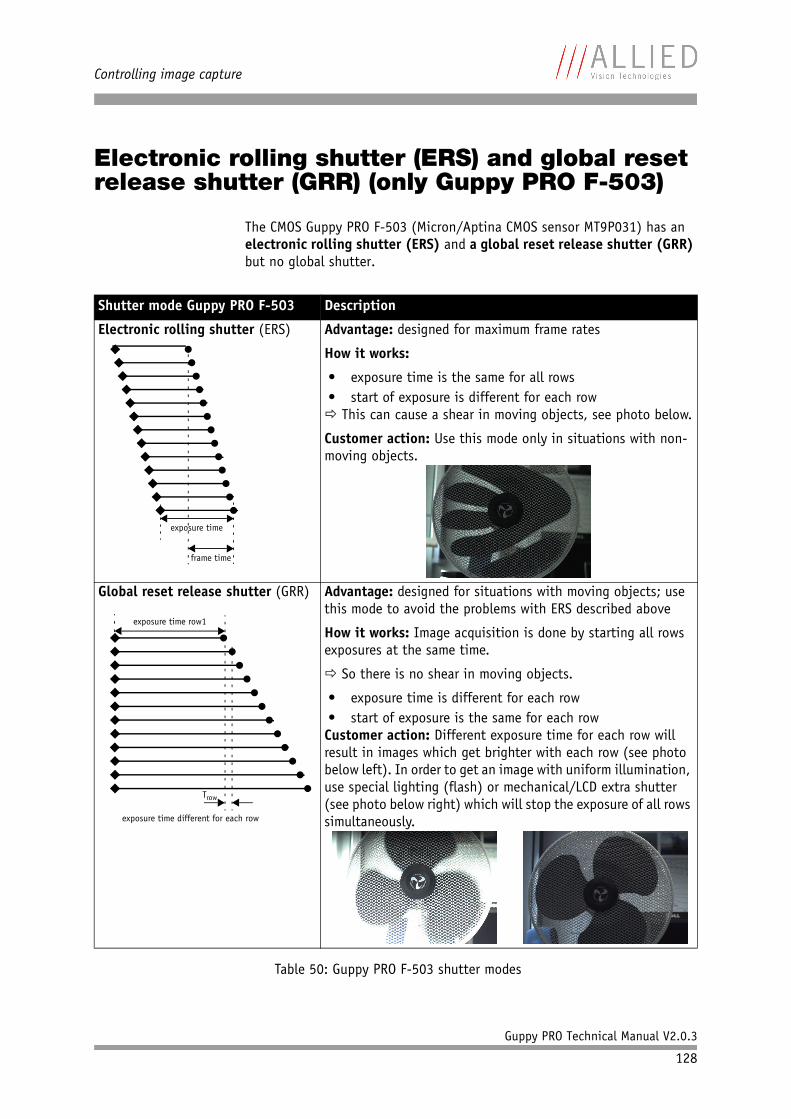
Controlling image capture
Guppy PRO Technical Manual V2.0.3
128
Electronic rolling shutter (ERS) and global reset release shutter (GRR) (only Guppy PRO F-503)
The CMOS Guppy PRO F-503 (Micron/Aptina CMOS sensor MT9P031) has an electronic rolling shutter (ERS) and a global reset release shutter (GRR) but no global shutter.
Shutter mode Guppy PRO F-503 Description
Electronic rolling shutter (ERS) Advantage: designed for maximum frame rates
How it works:
• exposure time is the same for all rows• start of exposure is different for each row This can cause a shear in moving objects, see photo below.
Customer action: Use this mode only in situations with non-moving objects.
Global reset release shutter (GRR) Advantage: designed for situations with moving objects; use this mode to avoid the problems with ERS described above
How it works: Image acquisition is done by starting all rows exposures at the same time.
So there is no shear in moving objects.
• exposure time is different for each row• start of exposure is the same for each rowCustomer action: Different exposure time for each row will result in images which get brighter with each row (see photo below left). In order to get an image with uniform illumination, use special lighting (flash) or mechanical/LCD extra shutter (see photo below right) which will stop the exposure of all rows simultaneously.
Table 50: Guppy PRO F-503 shutter modes
frame time
exposure time
exposure time different for each row
Trow
exposure time row1
Controlling image capture
Guppy PRO Technical Manual V2.0.3
129
Trigger modes
Guppy PRO cameras support IIDC conforming Trigger_Mode_0 and Trigger_Mode_1 and special Trigger_Mode_15 (bulk trigger).
Note
CMOS cameras Guppy PRO F-503 support only Trigger_Mode_0.
Trigger mode also known as Description
Trigger_Mode_0 Edge mode Sets the shutter time according to the value set in the shutter (or extended shutter) register
Trigger_Mode_1 Level mode Sets the shutter time according to the active low time of the pulse applied (or active high time in the case of an inverting input)
Trigger_Mode_15 Programmable mode Is a bulk trigger, combining one external trigger event with continuous or one-shot or multi-shot internal trigger
Table 51: Trigger modes
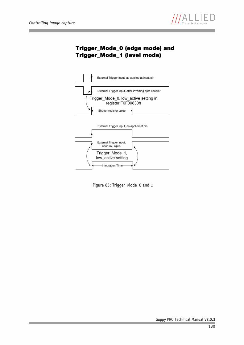
Controlling image capture
Guppy PRO Technical Manual V2.0.3
130
Trigger_Mode_0 (edge mode) and Trigger_Mode_1 (level mode)
Figure 63: Trigger_Mode_0 and 1
Shutter register value
External Trigger input, after inverting opto coupler
Integration Time
External Trigger input, after inv. Opto.
External Trigger input, as applied at input pin
External Trigger input, as applied at pin
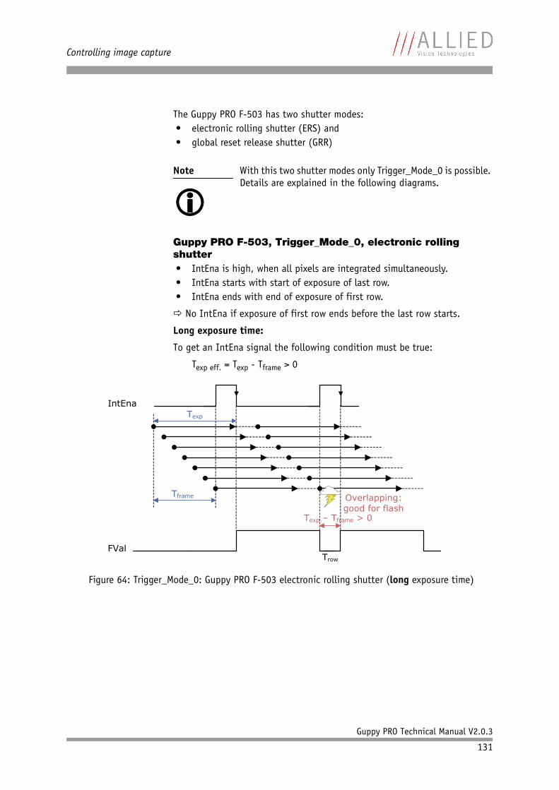
Controlling image capture
Guppy PRO Technical Manual V2.0.3
131
The Guppy PRO F-503 has two shutter modes:• electronic rolling shutter (ERS) and• global reset release shutter (GRR)
Guppy PRO F-503, Trigger_Mode_0, electronic rolling shutter• IntEna is high, when all pixels are integrated simultaneously.• IntEna starts with start of exposure of last row.• IntEna ends with end of exposure of first row.
No IntEna if exposure of first row ends before the last row starts.
Long exposure time:
To get an IntEna signal the following condition must be true:
Texp eff. = Texp - Tframe > 0
Note
With this two shutter modes only Trigger_Mode_0 is possible. Details are explained in the following diagrams.
Figure 64: Trigger_Mode_0: Guppy PRO F-503 electronic rolling shutter (long exposure time)
IntEna
Trow
FVal
Texp
Tframe Overlapping: good for flash
Texp – Tframe > 0
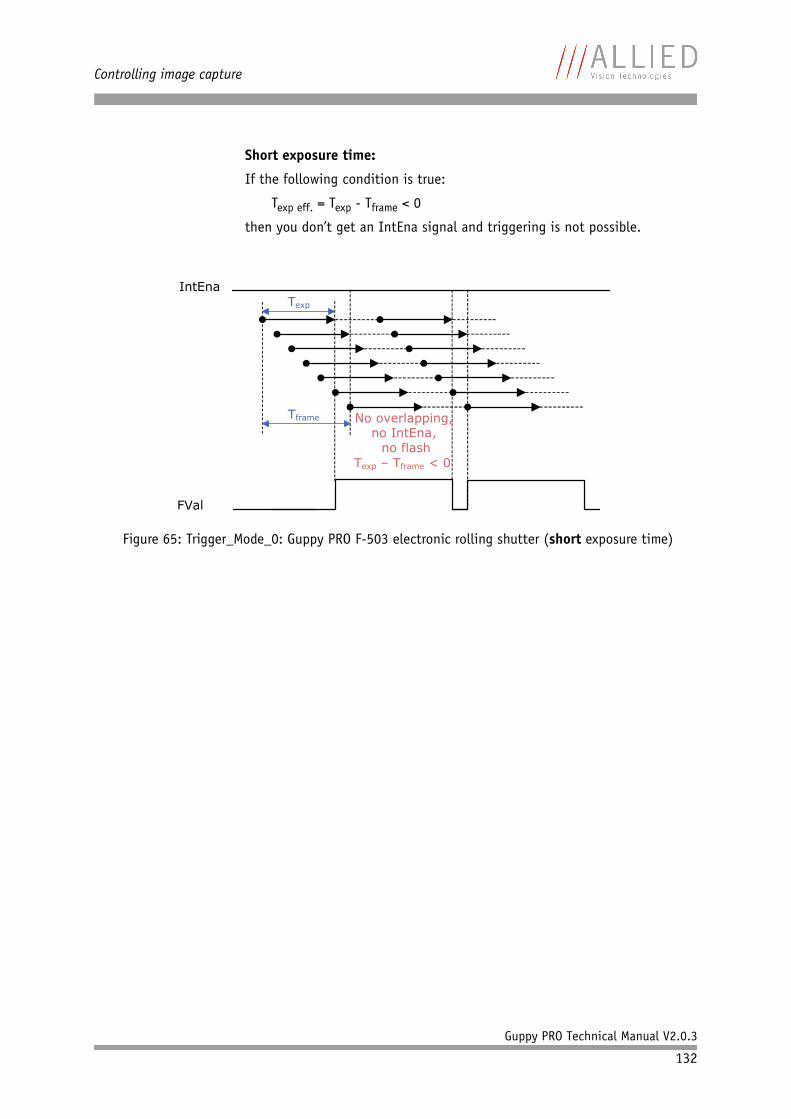
Controlling image capture
Guppy PRO Technical Manual V2.0.3
132
Short exposure time:
If the following condition is true:
Texp eff. = Texp - Tframe < 0
then you don’t get an IntEna signal and triggering is not possible.
Figure 65: Trigger_Mode_0: Guppy PRO F-503 electronic rolling shutter (short exposure time)
IntEnaTexp
Tframe No overlapping,no IntEna, no flash
Texp – Tframe < 0
FVal
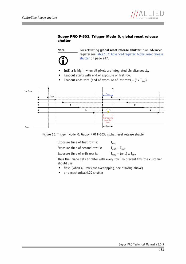
Controlling image capture
Guppy PRO Technical Manual V2.0.3
133
Guppy PRO F-503, Trigger_Mode_0, global reset release shutter
• IntEna is high, when all pixels are integrated simultaneously.• Readout starts with end of exposure of first row.• Readout ends with (end of exposure of last row) + (1x Trow).
Exposure time of first row is: Texp
Exposure time of second row is: Texp + Trow
Exposure time of n-th row is: Texp + (n-1) x Trow
Thus the image gets brighter with every row. To prevent this the customer should use:• flash (when all rows are overlapping, see drawing above)• or a mechanical/LCD shutter
Note
For activating global reset release shutter in an advanced register see Table 137: Advanced register: Global reset release shutter on page 247.
Figure 66: Trigger_Mode_0: Guppy PRO F-503: global reset release shutter
IntEna
FVal
Trow
Texp
Overlappinggood for
flash
Texp
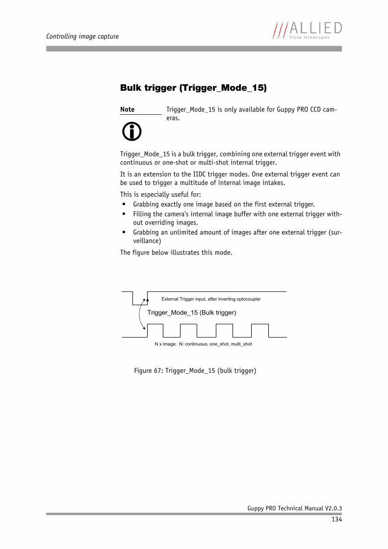
Controlling image capture
Guppy PRO Technical Manual V2.0.3
134
Bulk trigger (Trigger_Mode_15)
Trigger_Mode_15 is a bulk trigger, combining one external trigger event with continuous or one-shot or multi-shot internal trigger.
It is an extension to the IIDC trigger modes. One external trigger event can be used to trigger a multitude of internal image intakes.
This is especially useful for:• Grabbing exactly one image based on the first external trigger.• Filling the camera's internal image buffer with one external trigger with-
out overriding images.• Grabbing an unlimited amount of images after one external trigger (sur-
veillance)
The figure below illustrates this mode.
Note
Trigger_Mode_15 is only available for Guppy PRO CCD cam-eras.
Figure 67: Trigger_Mode_15 (bulk trigger)
External Trigger input, after inverting optocoupler
N x image; N: continuous, one_shot, multi_shot
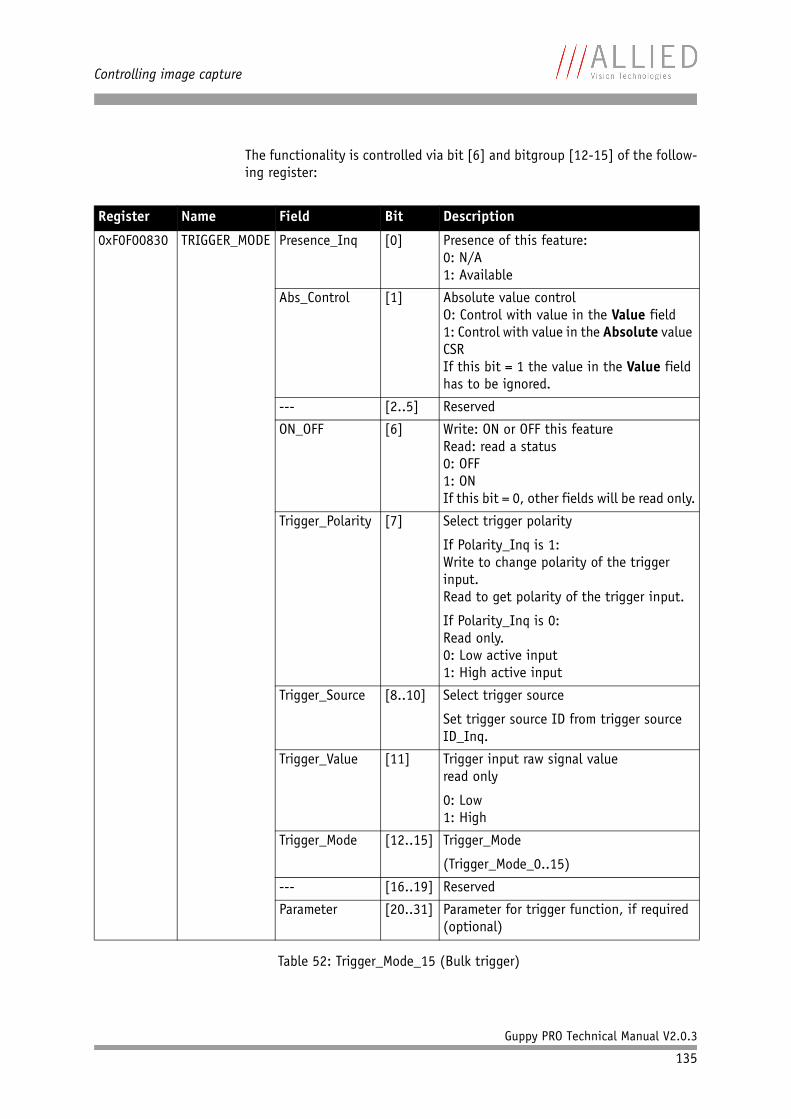
Controlling image capture
Guppy PRO Technical Manual V2.0.3
135
The functionality is controlled via bit [6] and bitgroup [12-15] of the follow-ing register:
Register Name Field Bit Description
0xF0F00830 TRIGGER_MODE Presence_Inq [0] Presence of this feature:0: N/A1: Available
Abs_Control [1] Absolute value controlO: Control with value in the Value field1: Control with value in the Absolute value CSRIf this bit = 1 the value in the Value field has to be ignored.
--- [2..5] Reserved
ON_OFF [6] Write: ON or OFF this featureRead: read a status0: OFF1: ONIf this bit = 0, other fields will be read only.
Trigger_Polarity [7] Select trigger polarity
If Polarity_Inq is 1:Write to change polarity of the trigger input.Read to get polarity of the trigger input.
If Polarity_Inq is 0:Read only.0: Low active input1: High active input
Trigger_Source [8..10] Select trigger source
Set trigger source ID from trigger source ID_Inq.
Trigger_Value [11] Trigger input raw signal valueread only
0: Low1: High
Trigger_Mode [12..15] Trigger_Mode
(Trigger_Mode_0..15)
--- [16..19] Reserved
Parameter [20..31] Parameter for trigger function, if required (optional)
Table 52: Trigger_Mode_15 (Bulk trigger)
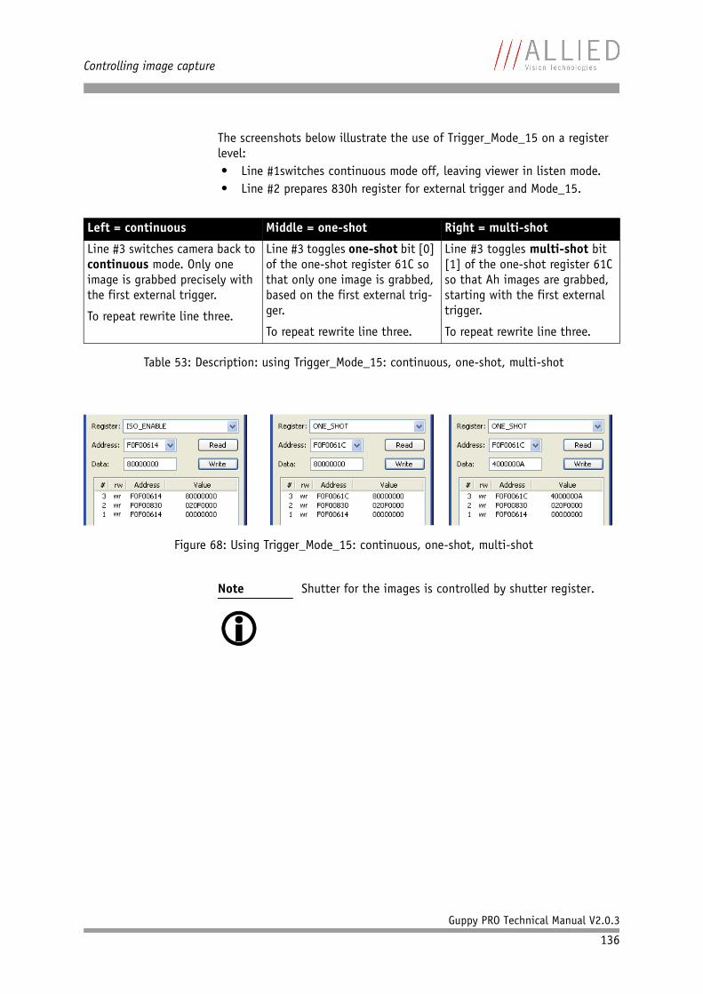
Controlling image capture
Guppy PRO Technical Manual V2.0.3
136
The screenshots below illustrate the use of Trigger_Mode_15 on a register level:• Line #1switches continuous mode off, leaving viewer in listen mode.• Line #2 prepares 830h register for external trigger and Mode_15.
Left = continuous Middle = one-shot Right = multi-shot
Line #3 switches camera back to continuous mode. Only one image is grabbed precisely with the first external trigger.
To repeat rewrite line three.
Line #3 toggles one-shot bit [0] of the one-shot register 61C so that only one image is grabbed, based on the first external trig-ger.
To repeat rewrite line three.
Line #3 toggles multi-shot bit [1] of the one-shot register 61C so that Ah images are grabbed, starting with the first external trigger.
To repeat rewrite line three.
Table 53: Description: using Trigger_Mode_15: continuous, one-shot, multi-shot
Figure 68: Using Trigger_Mode_15: continuous, one-shot, multi-shot
Note
Shutter for the images is controlled by shutter register.
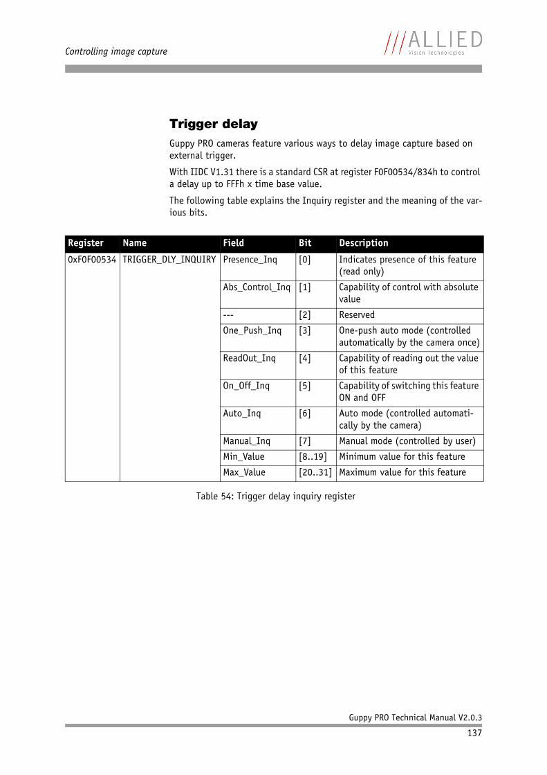
Controlling image capture
Guppy PRO Technical Manual V2.0.3
137
Trigger delayGuppy PRO cameras feature various ways to delay image capture based on external trigger.
With IIDC V1.31 there is a standard CSR at register F0F00534/834h to control a delay up to FFFh x time base value.
The following table explains the Inquiry register and the meaning of the var-ious bits.
Register Name Field Bit Description
0xF0F00534 TRIGGER_DLY_INQUIRY Presence_Inq [0] Indicates presence of this feature (read only)
Abs_Control_Inq [1] Capability of control with absolute value
--- [2] Reserved
One_Push_Inq [3] One-push auto mode (controlled automatically by the camera once)
ReadOut_Inq [4] Capability of reading out the value of this feature
On_Off_Inq [5] Capability of switching this feature ON and OFF
Auto_Inq [6] Auto mode (controlled automati-cally by the camera)
Manual_Inq [7] Manual mode (controlled by user)
Min_Value [8..19] Minimum value for this feature
Max_Value [20..31] Maximum value for this feature
Table 54: Trigger delay inquiry register
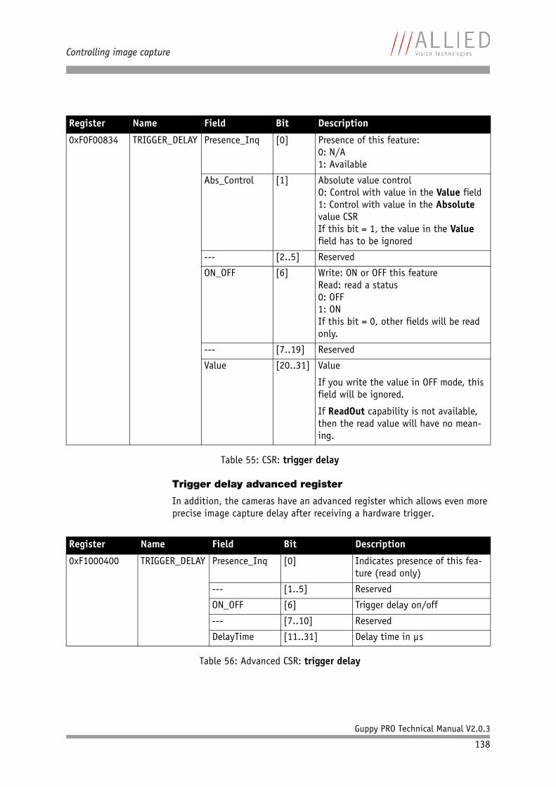
Controlling image capture
Guppy PRO Technical Manual V2.0.3
138
Trigger delay advanced register
In addition, the cameras have an advanced register which allows even more precise image capture delay after receiving a hardware trigger.
Register Name Field Bit Description
0xF0F00834 TRIGGER_DELAY Presence_Inq [0] Presence of this feature:0: N/A1: Available
Abs_Control [1] Absolute value controlO: Control with value in the Value field1: Control with value in the Absolute value CSRIf this bit = 1, the value in the Value field has to be ignored
--- [2..5] Reserved
ON_OFF [6] Write: ON or OFF this featureRead: read a status0: OFF1: ONIf this bit = 0, other fields will be read only.
--- [7..19] Reserved
Value [20..31] Value
If you write the value in OFF mode, this field will be ignored.
If ReadOut capability is not available, then the read value will have no mean-ing.
Table 55: CSR: trigger delay
Register Name Field Bit Description
0xF1000400 TRIGGER_DELAY Presence_Inq [0] Indicates presence of this fea-ture (read only)
--- [1..5] Reserved
ON_OFF [6] Trigger delay on/off
--- [7..10] Reserved
DelayTime [11..31] Delay time in µs
Table 56: Advanced CSR: trigger delay
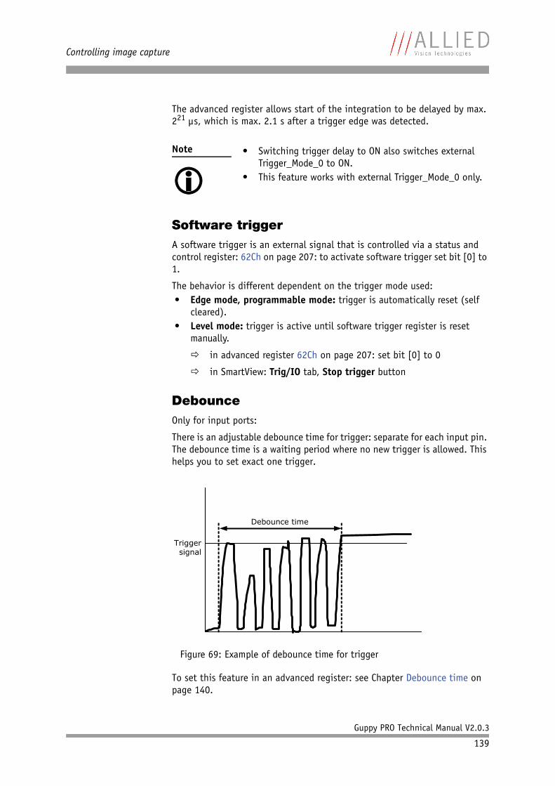
Controlling image capture
Guppy PRO Technical Manual V2.0.3
139
The advanced register allows start of the integration to be delayed by max. 221 µs, which is max. 2.1 s after a trigger edge was detected.
Software triggerA software trigger is an external signal that is controlled via a status and control register: 62Ch on page 207: to activate software trigger set bit [0] to 1.
The behavior is different dependent on the trigger mode used:• Edge mode, programmable mode: trigger is automatically reset (self
cleared).• Level mode: trigger is active until software trigger register is reset
manually.
in advanced register 62Ch on page 207: set bit [0] to 0
in SmartView: Trig/IO tab, Stop trigger button
DebounceOnly for input ports:
There is an adjustable debounce time for trigger: separate for each input pin. The debounce time is a waiting period where no new trigger is allowed. This helps you to set exact one trigger.
To set this feature in an advanced register: see Chapter Debounce time on page 140.
Note
• Switching trigger delay to ON also switches external
Trigger_Mode_0 to ON.• This feature works with external Trigger_Mode_0 only.
Figure 69: Example of debounce time for trigger
Triggersignal
Debounce time
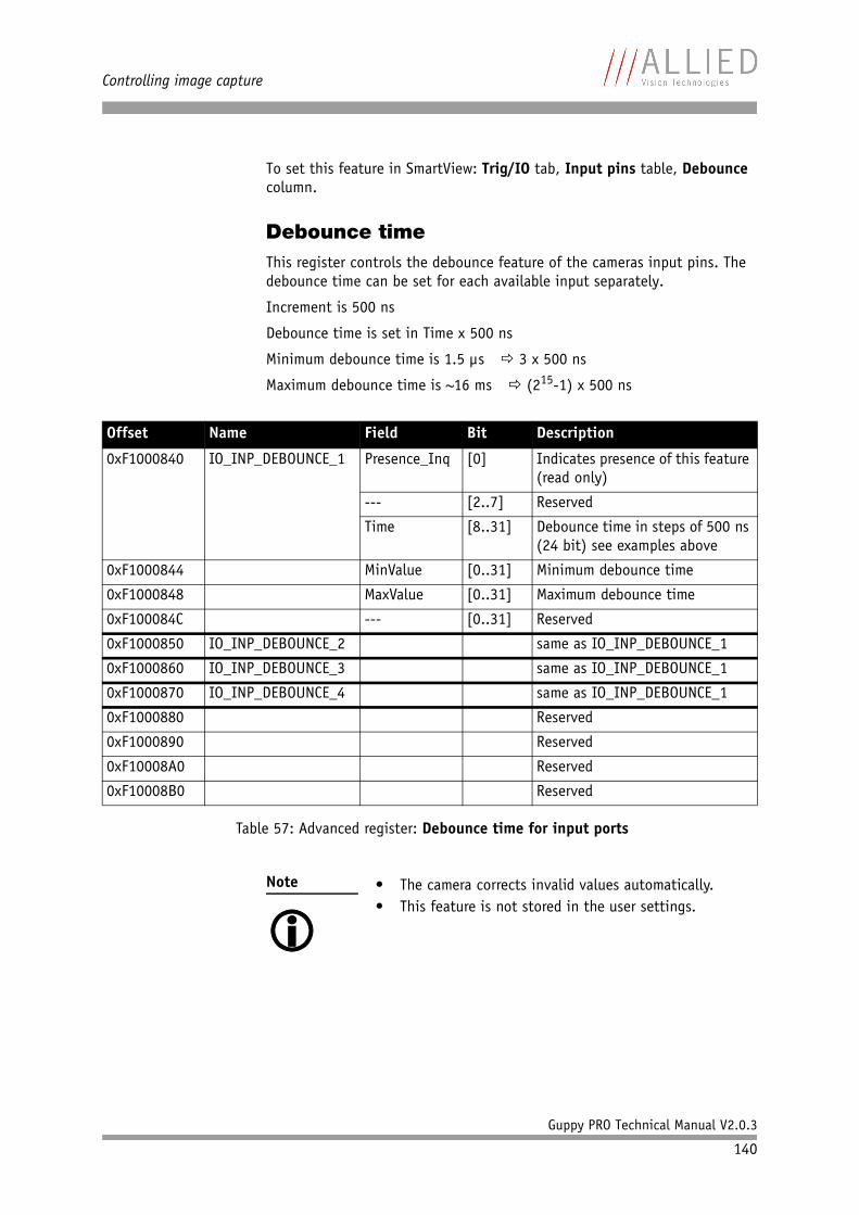
Controlling image capture
Guppy PRO Technical Manual V2.0.3
140
To set this feature in SmartView: Trig/IO tab, Input pins table, Debounce column.
Debounce timeThis register controls the debounce feature of the cameras input pins. The debounce time can be set for each available input separately.
Increment is 500 ns
Debounce time is set in Time x 500 ns
Minimum debounce time is 1.5 µs 3 x 500 ns
Maximum debounce time is ~16 ms (215-1) x 500 ns
Offset Name Field Bit Description
0xF1000840 IO_INP_DEBOUNCE_1 Presence_Inq [0] Indicates presence of this feature (read only)
--- [2..7] Reserved
Time [8..31] Debounce time in steps of 500 ns (24 bit) see examples above
0xF1000844 MinValue [0..31] Minimum debounce time
0xF1000848 MaxValue [0..31] Maximum debounce time
0xF100084C --- [0..31] Reserved
0xF1000850 IO_INP_DEBOUNCE_2 same as IO_INP_DEBOUNCE_1
0xF1000860 IO_INP_DEBOUNCE_3 same as IO_INP_DEBOUNCE_1
0xF1000870 IO_INP_DEBOUNCE_4 same as IO_INP_DEBOUNCE_1
0xF1000880 Reserved
0xF1000890 Reserved
0xF10008A0 Reserved
0xF10008B0 Reserved
Table 57: Advanced register: Debounce time for input ports
Note
• The camera corrects invalid values automatically.• This feature is not stored in the user settings.
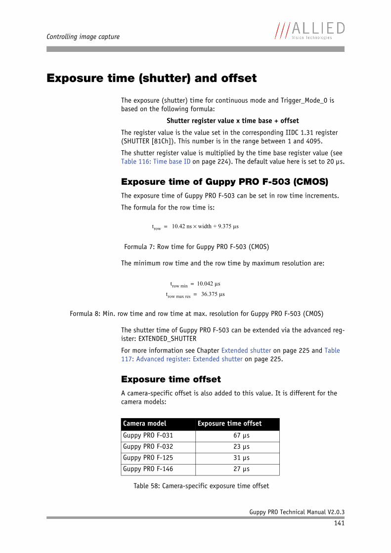
Controlling image capture
Guppy PRO Technical Manual V2.0.3
141
Exposure time (shutter) and offset
The exposure (shutter) time for continuous mode and Trigger_Mode_0 is based on the following formula:
Shutter register value x time base + offset
The register value is the value set in the corresponding IIDC 1.31 register (SHUTTER [81Ch]). This number is in the range between 1 and 4095.
The shutter register value is multiplied by the time base register value (see Table 116: Time base ID on page 224). The default value here is set to 20 µs.
Exposure time of Guppy PRO F-503 (CMOS)The exposure time of Guppy PRO F-503 can be set in row time increments.
The formula for the row time is:
The minimum row time and the row time by maximum resolution are:
The shutter time of Guppy PRO F-503 can be extended via the advanced reg-ister: EXTENDED_SHUTTER
For more information see Chapter Extended shutter on page 225 and Table 117: Advanced register: Extended shutter on page 225.
Exposure time offsetA camera-specific offset is also added to this value. It is different for the camera models:
Formula 7: Row time for Guppy PRO F-503 (CMOS)
Formula 8: Min. row time and row time at max. resolution for Guppy PRO F-503 (CMOS)
Camera model Exposure time offset
Guppy PRO F-031 67 µs
Guppy PRO F-032 23 µs
Guppy PRO F-125 31 µs
Guppy PRO F-146 27 µs
Table 58: Camera-specific exposure time offset
trow 10.42 ns width + 9.375 µs=
trow min 10.042 µs=
trow max res 36.375 µs=
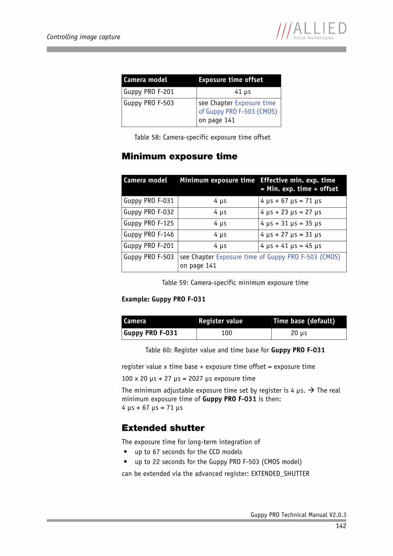
Controlling image capture
Guppy PRO Technical Manual V2.0.3
142
Minimum exposure time
Example: Guppy PRO F-031
register value x time base + exposure time offset = exposure time
100 x 20 µs + 27 µs = 2027 µs exposure time
The minimum adjustable exposure time set by register is 4 µs. The real minimum exposure time of Guppy PRO F-031 is then:4 µs + 67 µs = 71 µs
Extended shutterThe exposure time for long-term integration of• up to 67 seconds for the CCD models• up to 22 seconds for the Guppy PRO F-503 (CMOS model)
can be extended via the advanced register: EXTENDED_SHUTTER
Guppy PRO F-201 41 µs
Guppy PRO F-503 see Chapter Exposure time of Guppy PRO F-503 (CMOS) on page 141
Camera model Minimum exposure time Effective min. exp. time= Min. exp. time + offset
Guppy PRO F-031 4 µs 4 µs + 67 µs = 71 µs
Guppy PRO F-032 4 µs 4 µs + 23 µs = 27 µs
Guppy PRO F-125 4 µs 4 µs + 31 µs = 35 µs
Guppy PRO F-146 4 µs 4 µs + 27 µs = 31 µs
Guppy PRO F-201 4 µs 4 µs + 41 µs = 45 µs
Guppy PRO F-503 see Chapter Exposure time of Guppy PRO F-503 (CMOS) on page 141
Table 59: Camera-specific minimum exposure time
Camera Register value Time base (default)
Guppy PRO F-031 100 20 µs
Table 60: Register value and time base for Guppy PRO F-031
Camera model Exposure time offset
Table 58: Camera-specific exposure time offset
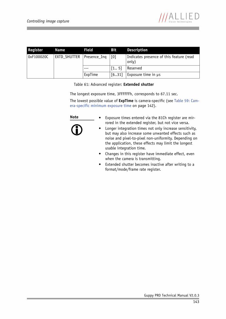
Controlling image capture
Guppy PRO Technical Manual V2.0.3
143
The longest exposure time, 3FFFFFFh, corresponds to 67.11 sec.
The lowest possible value of ExpTime is camera-specific (see Table 59: Cam-era-specific minimum exposure time on page 142).
Register Name Field Bit Description
0xF100020C EXTD_SHUTTER Presence_Inq [0] Indicates presence of this feature (read only)
--- [1.. 5] Reserved
ExpTime [6..31] Exposure time in µs
Table 61: Advanced register: Extended shutter
Note
• Exposure times entered via the 81Ch register are mir-
rored in the extended register, but not vice versa.• Longer integration times not only increase sensitivity,
but may also increase some unwanted effects such as noise and pixel-to-pixel non-uniformity. Depending on the application, these effects may limit the longest usable integration time.
• Changes in this register have immediate effect, even when the camera is transmitting.
• Extended shutter becomes inactive after writing to a format/mode/frame rate register.
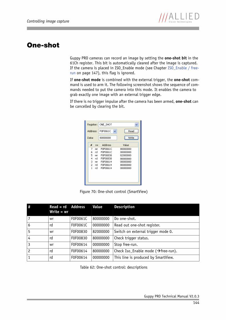
Controlling image capture
Guppy PRO Technical Manual V2.0.3
144
One-shot
Guppy PRO cameras can record an image by setting the one-shot bit in the 61Ch register. This bit is automatically cleared after the image is captured. If the camera is placed in ISO_Enable mode (see Chapter ISO_Enable / free-run on page 147), this flag is ignored.
If one-shot mode is combined with the external trigger, the one-shot com-mand is used to arm it. The following screenshot shows the sequence of com-mands needed to put the camera into this mode. It enables the camera to grab exactly one image with an external trigger edge.
If there is no trigger impulse after the camera has been armed, one-shot can be cancelled by clearing the bit.
Figure 70: One-shot control (SmartView)
# Read = rdWrite = wr
Address Value Description
7 wr F0F0061C 80000000 Do one-shot.
6 rd F0F0061C 00000000 Read out one-shot register.
5 wr F0F00830 82000000 Switch on external trigger mode 0.
4 rd F0F00830 80000000 Check trigger status.
3 wr F0F00614 00000000 Stop free-run.
2 rd F0F00614 80000000 Check Iso_Enable mode (free-run).
1 rd F0F00614 00000000 This line is produced by SmartView.
Table 62: One-shot control: descriptions
Controlling image capture
Guppy PRO Technical Manual V2.0.3
145
One-shot command on the bus to start of exposureThe following sections describe the time response of the camera using a sin-gle frame (one-shot) command. As set out in the IIDC specification, this is a software command that causes the camera to record and transmit a single frame.
The following values apply only when the camera is idle and ready for use. Full resolution must also be set.
Microcontroller sync is an internal signal. It is generated by the microcon-troller to initiate a trigger. This can either be a direct trigger or a release for ExSync if the camera is externally triggered.
Feature Value
One-shot microcontroller sync 150 µs (processing time in the microcontroller)
µC-Sync/ExSync integration start 8 µs
Table 63: Values for one-shot
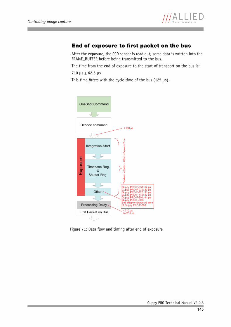
Controlling image capture
Guppy PRO Technical Manual V2.0.3
146
End of exposure to first packet on the busAfter the exposure, the CCD sensor is read out; some data is written into the FRAME_BUFFER before being transmitted to the bus.
The time from the end of exposure to the start of transport on the bus is:
710 µs ± 62.5 µs
This time jitters with the cycle time of the bus (125 µs).
Figure 71: Data flow and timing after end of exposure
OneShot Command
Decode command
Exp
osur
e
Integration-Start
Timebase Reg. X
Shutter-Reg.
Offset
Processing Delay
< 150s
Guppy PRO F-031: 67 µsGuppy PRO F-032: 23 µsGuppy PRO F-125: 31 µsGuppy PRO F-146: 27 µsGuppy PRO F-201: 41 µsGuppy PRO F-503: See chapter Exposure time of Guppy PRO F-503
Tim
eba
se x
Shu
tter
+ O
ffse
t = E
xpos
ure
Tim
e
First Packet on Bus< 710s+/-62.5 s
Controlling image capture
Guppy PRO Technical Manual V2.0.3
147
Multi-shot
Setting multi-shot and entering a quantity of images in Count_Number in the 61Ch register enables the camera to record a specified number of images.
The number is indicated in bits 16 to 31. If the camera is put into ISO_Enable mode (see Chapter ISO_Enable / free-run on page 147), this flag is ignored and deleted automatically once all the images have been recorded.
If multi-shot mode is activated and the images have not yet all been cap-tured, it can be cancelled by resetting the flag. The same result can be achieved by setting the number of images to 0.
Multi-shot can also be combined with the external trigger in order to grab a certain number of images based on an external trigger.
ISO_Enable / free-run
Setting the MSB (bit 0) in the 614h register (ISO_ENA) puts the camera into ISO_Enable mode or Continuous_Shot (free-run). The camera captures an infinite series of images. This operation can be quit by deleting the 0 bit.
Asynchronous broadcast
The camera accepts asynchronous broadcasts. This involves asynchronous write requests that use node number 63 as the target node with no acknowledge.
This makes it possible for all cameras on a bus to be triggered by software simultaneously - e.g. by broadcasting a one-shot. All cameras receive the one-shot command in the same IEEE 1394 bus cycle. This creates uncertainty for all cameras in the range of 125 µs.
Inter-camera latency is described in Chapter Jitter at start of exposure on page 148.
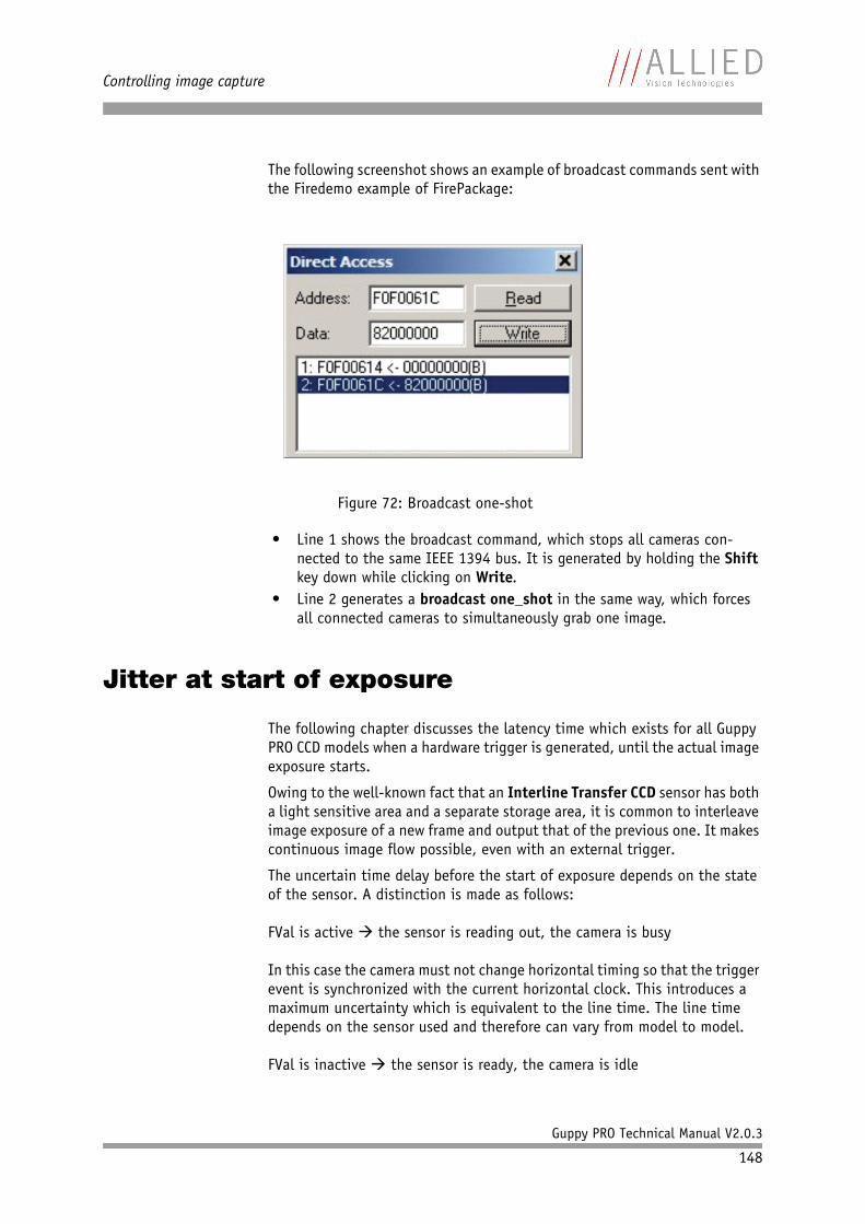
Controlling image capture
Guppy PRO Technical Manual V2.0.3
148
The following screenshot shows an example of broadcast commands sent with the Firedemo example of FirePackage:
• Line 1 shows the broadcast command, which stops all cameras con-nected to the same IEEE 1394 bus. It is generated by holding the Shift key down while clicking on Write.
• Line 2 generates a broadcast one_shot in the same way, which forces all connected cameras to simultaneously grab one image.
Jitter at start of exposure
The following chapter discusses the latency time which exists for all Guppy PRO CCD models when a hardware trigger is generated, until the actual image exposure starts.
Owing to the well-known fact that an Interline Transfer CCD sensor has both a light sensitive area and a separate storage area, it is common to interleave image exposure of a new frame and output that of the previous one. It makes continuous image flow possible, even with an external trigger.
The uncertain time delay before the start of exposure depends on the state of the sensor. A distinction is made as follows:
FVal is active the sensor is reading out, the camera is busy
In this case the camera must not change horizontal timing so that the trigger event is synchronized with the current horizontal clock. This introduces a maximum uncertainty which is equivalent to the line time. The line time depends on the sensor used and therefore can vary from model to model.
FVal is inactive the sensor is ready, the camera is idle
Figure 72: Broadcast one-shot
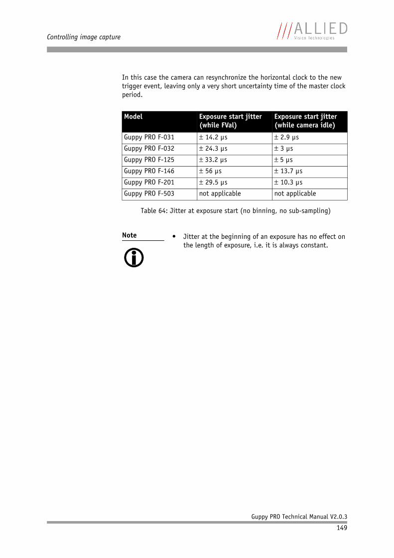
Controlling image capture
Guppy PRO Technical Manual V2.0.3
149
In this case the camera can resynchronize the horizontal clock to the new trigger event, leaving only a very short uncertainty time of the master clock period.
Model Exposure start jitter (while FVal)
Exposure start jitter (while camera idle)
Guppy PRO F-031 14.2 µs 2.9 µs
Guppy PRO F-032 24.3 µs 3 µs
Guppy PRO F-125 33.2 µs 5 µs
Guppy PRO F-146 56 µs 13.7 µs
Guppy PRO F-201 29.5 µs 10.3 µs
Guppy PRO F-503 not applicable not applicable
Table 64: Jitter at exposure start (no binning, no sub-sampling)
Note
• Jitter at the beginning of an exposure has no effect on
the length of exposure, i.e. it is always constant.
Video formats, modes and bandwidth
Guppy PRO Technical Manual V2.0.3
150
Video formats, modes and bandwidth
The different Guppy PRO models support different video formats, modes and frame rates.
These formats and modes are standardized in the IIDC (formerly DCAM) specification.
Resolutions smaller than the generic sensor resolution are generated from the center of the sensor and without binning.
Note
• The maximum frame rates can only be achieved with
shutter settings lower than 1/framerate. This means that with default shutter time of 40 ms, a camera will not achieve frame rates higher than 25 frames/s. In order to achieve higher frame rates, please reduce the shutter time proportionally.
• The following tables assume that bus speed is 800 Mbit/s. With lower bus speeds (e.g. 400, 200 or 100 Mbit/s) not all frame rates may be achieved.
• For information on bit/pixel and byte/pixel for each color mode see Table 87: ByteDepth on page 179.
Note
The following Format_7 tables show default Format_7 modes without Format_7 mode mapping.
For information on Format_7 mode mapping ...
• ... see Chapter Mapping of possible Format_7 modes to F7M1...F7M7 (F-503 only) For default mappings per factory see page 162 on page 120
• ... see Chapter Format_7 mode mapping (only Guppy PRO F-503) on page 241
Note
H-binning means horizontal binning.
V-binning means vertical binning.
Full binning (H+V) means horizontal + vertical binning
2 x binning means: 2 neighboring pixels are combined.
4 x binning means: 4 neighboring pixels are combined.
• Binning increases signal-to-noise ratio (SNR), but decreases resolution.
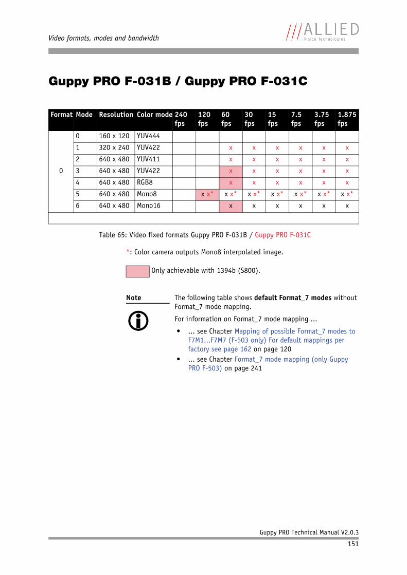
Video formats, modes and bandwidth
Guppy PRO Technical Manual V2.0.3
151
Guppy PRO F-031B / Guppy PRO F-031C
*: Color camera outputs Mono8 interpolated image.
Format Mode Resolution Color mode 240 fps
120 fps
60 fps
30 fps
15 fps
7.5 fps
3.75 fps
1.875 fps
0
0 160 x 120 YUV444
1 320 x 240 YUV422 x x x x x x
2 640 x 480 YUV411 x x x x x x
3 640 x 480 YUV422 x x x x x x
4 640 x 480 RGB8 x x x x x x
5 640 x 480 Mono8 x x* x x* x x* x x* x x* x x* x x*
6 640 x 480 Mono16 x x x x x x
Table 65: Video fixed formats Guppy PRO F-031B / Guppy PRO F-031C
Only achievable with 1394b (S800).
Note
The following table shows default Format_7 modes without Format_7 mode mapping.
For information on Format_7 mode mapping ...
• ... see Chapter Mapping of possible Format_7 modes to F7M1...F7M7 (F-503 only) For default mappings per factory see page 162 on page 120
• ... see Chapter Format_7 mode mapping (only Guppy PRO F-503) on page 241

Video formats, modes and bandwidth
Guppy PRO Technical Manual V2.0.3
152
Format Mode Resolution Color mode Maximal S800 frame rates for Format_7 modes
7
0 656 x 492
656 x 492
Mono8Mono12Mono16
YUV411YUV422,Raw16Mono8,Raw8RGB8Raw12
121 fps121 fps121 fps
121 fps121 fps121 fps66 fps121 fps
1 328 x 492 Mono8Mono12Mono16
123 fps 2x H-binning122 fps 2x H-binning121 fps 2x H-binning
2 656 x 246 Mono8Mono12Mono16
204 fps 2x V-binning204 fps 2x V-binning194 fps 2x V-binning
3 328 x 246 Mono8Mono12Mono16
204 fps 2x H+V binning205 fps 2x H+V binning205 fps 2x H+V binning
4 328 x 492
Mono8Mono12Mono16
123 fps 2 out of 4 H-sub-sampling123 fps 2 out of 4 H-sub-sampling121 fps 2 out of 4 H-sub-sampling
5 656 x 246
Mono8Mono12Mono16
153 fps 2 out of 4 V-sub-sampling153 fps 2 out of 4 V-sub-sampling153 fps 2 out of 4 V-sub-sampling
6 328 x 246
Mono8Mono12Mono16
153 fps 2 out of 4 H+V sub-sampling153 fps 2 out of 4 H+V sub-sampling153 fps 2 out of 4 H+V sub-sampling
Table 66: Video Format_7 default modes Guppy PRO F-031B / Guppy PRO F-031C
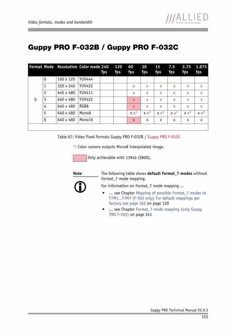
Video formats, modes and bandwidth
Guppy PRO Technical Manual V2.0.3
153
Guppy PRO F-032B / Guppy PRO F-032C
*: Color camera outputs Mono8 interpolated image.
Format Mode Resolution Color mode 240 fps
120 fps
60 fps
30 fps
15 fps
7.5 fps
3.75 fps
1.875 fps
0
0 160 x 120 YUV444
1 320 x 240 YUV422 x x x x x x
2 640 x 480 YUV411 x x x x x x
3 640 x 480 YUV422 x x x x x x
4 640 x 480 RGB8 x x x x x x
5 640 x 480 Mono8 x x* x x* x x* x x* x x* x x*
6 640 x 480 Mono16 x x x x x x
Table 67: Video fixed formats Guppy PRO F-032B / Guppy PRO F-032C
Only achievable with 1394b (S800).
Note
The following table shows default Format_7 modes without Format_7 mode mapping.
For information on Format_7 mode mapping ...
• ... see Chapter Mapping of possible Format_7 modes to F7M1...F7M7 (F-503 only) For default mappings per factory see page 162 on page 120
• ... see Chapter Format_7 mode mapping (only Guppy PRO F-503) on page 241
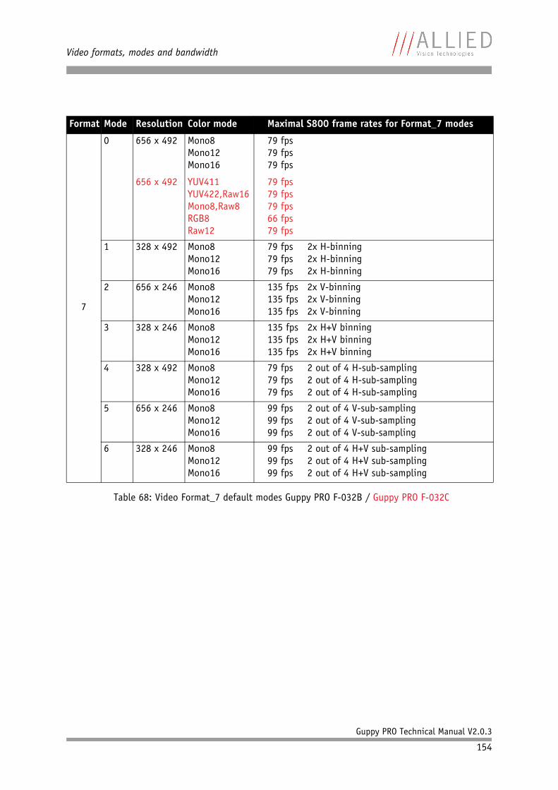
Video formats, modes and bandwidth
Guppy PRO Technical Manual V2.0.3
154
Format Mode Resolution Color mode Maximal S800 frame rates for Format_7 modes
7
0 656 x 492
656 x 492
Mono8Mono12Mono16
YUV411YUV422,Raw16Mono8,Raw8RGB8Raw12
79 fps79 fps79 fps
79 fps79 fps79 fps66 fps79 fps
1 328 x 492 Mono8Mono12Mono16
79 fps 2x H-binning79 fps 2x H-binning79 fps 2x H-binning
2 656 x 246 Mono8Mono12Mono16
135 fps 2x V-binning135 fps 2x V-binning135 fps 2x V-binning
3 328 x 246 Mono8Mono12Mono16
135 fps 2x H+V binning135 fps 2x H+V binning135 fps 2x H+V binning
4 328 x 492
Mono8Mono12Mono16
79 fps 2 out of 4 H-sub-sampling79 fps 2 out of 4 H-sub-sampling79 fps 2 out of 4 H-sub-sampling
5 656 x 246
Mono8Mono12Mono16
99 fps 2 out of 4 V-sub-sampling99 fps 2 out of 4 V-sub-sampling99 fps 2 out of 4 V-sub-sampling
6 328 x 246
Mono8Mono12Mono16
99 fps 2 out of 4 H+V sub-sampling99 fps 2 out of 4 H+V sub-sampling99 fps 2 out of 4 H+V sub-sampling
Table 68: Video Format_7 default modes Guppy PRO F-032B / Guppy PRO F-032C
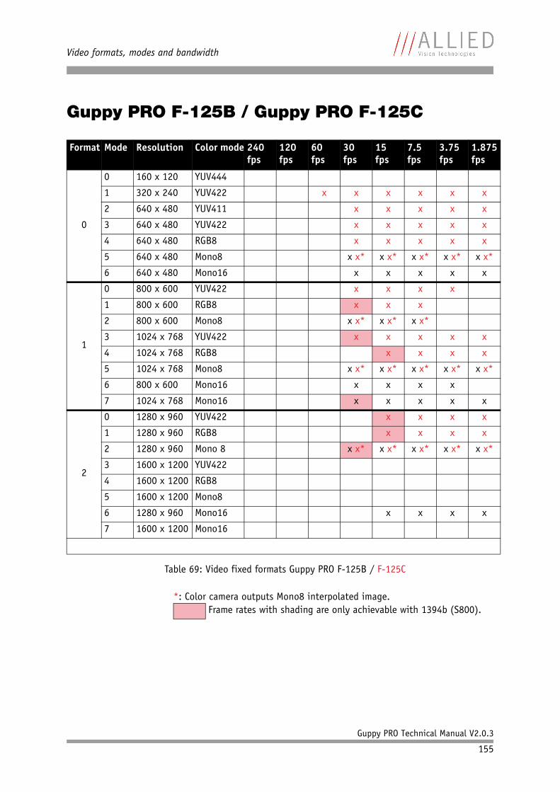
Video formats, modes and bandwidth
Guppy PRO Technical Manual V2.0.3
155
Guppy PRO F-125B / Guppy PRO F-125C
*: Color camera outputs Mono8 interpolated image.
Format Mode Resolution Color mode 240 fps
120 fps
60 fps
30 fps
15 fps
7.5 fps
3.75 fps
1.875 fps
0
0 160 x 120 YUV444
1 320 x 240 YUV422 x x x x x x
2 640 x 480 YUV411 x x x x x
3 640 x 480 YUV422 x x x x x
4 640 x 480 RGB8 x x x x x
5 640 x 480 Mono8 x x* x x* x x* x x* x x*
6 640 x 480 Mono16 x x x x x
1
0 800 x 600 YUV422 x x x x
1 800 x 600 RGB8 x x x
2 800 x 600 Mono8 x x* x x* x x*
3 1024 x 768 YUV422 x x x x x
4 1024 x 768 RGB8 x x x x
5 1024 x 768 Mono8 x x* x x* x x* x x* x x*
6 800 x 600 Mono16 x x x x
7 1024 x 768 Mono16 x x x x x
2
0 1280 x 960 YUV422 x x x x
1 1280 x 960 RGB8 x x x x
2 1280 x 960 Mono 8 x x* x x* x x* x x* x x*
3 1600 x 1200 YUV422
4 1600 x 1200 RGB8
5 1600 x 1200 Mono8
6 1280 x 960 Mono16 x x x x
7 1600 x 1200 Mono16
Table 69: Video fixed formats Guppy PRO F-125B / F-125C
Frame rates with shading are only achievable with 1394b (S800).
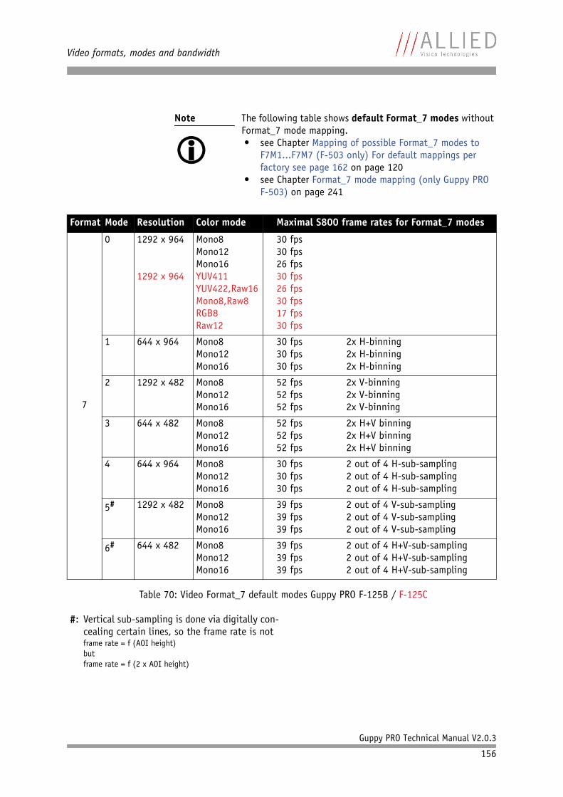
Video formats, modes and bandwidth
Guppy PRO Technical Manual V2.0.3
156
Note
The following table shows default Format_7 modes without Format_7 mode mapping.• see Chapter Mapping of possible Format_7 modes to
F7M1...F7M7 (F-503 only) For default mappings per factory see page 162 on page 120
• see Chapter Format_7 mode mapping (only Guppy PRO F-503) on page 241
Format Mode Resolution Color mode Maximal S800 frame rates for Format_7 modes
7
0 1292 x 964
1292 x 964
Mono8Mono12Mono16YUV411YUV422,Raw16Mono8,Raw8RGB8Raw12
30 fps30 fps26 fps30 fps26 fps30 fps17 fps30 fps
1 644 x 964 Mono8Mono12Mono16
30 fps 2x H-binning30 fps 2x H-binning30 fps 2x H-binning
2 1292 x 482 Mono8Mono12Mono16
52 fps 2x V-binning52 fps 2x V-binning52 fps 2x V-binning
3 644 x 482 Mono8Mono12Mono16
52 fps 2x H+V binning52 fps 2x H+V binning52 fps 2x H+V binning
4 644 x 964
Mono8Mono12Mono16
30 fps 2 out of 4 H-sub-sampling30 fps 2 out of 4 H-sub-sampling30 fps 2 out of 4 H-sub-sampling
5# 1292 x 482
Mono8Mono12Mono16
39 fps 2 out of 4 V-sub-sampling39 fps 2 out of 4 V-sub-sampling39 fps 2 out of 4 V-sub-sampling
6# 644 x 482
Mono8Mono12Mono16
39 fps 2 out of 4 H+V-sub-sampling39 fps 2 out of 4 H+V-sub-sampling39 fps 2 out of 4 H+V-sub-sampling
Table 70: Video Format_7 default modes Guppy PRO F-125B / F-125C
#: Vertical sub-sampling is done via digitally con-cealing certain lines, so the frame rate is notframe rate = f (AOI height)butframe rate = f (2 x AOI height)
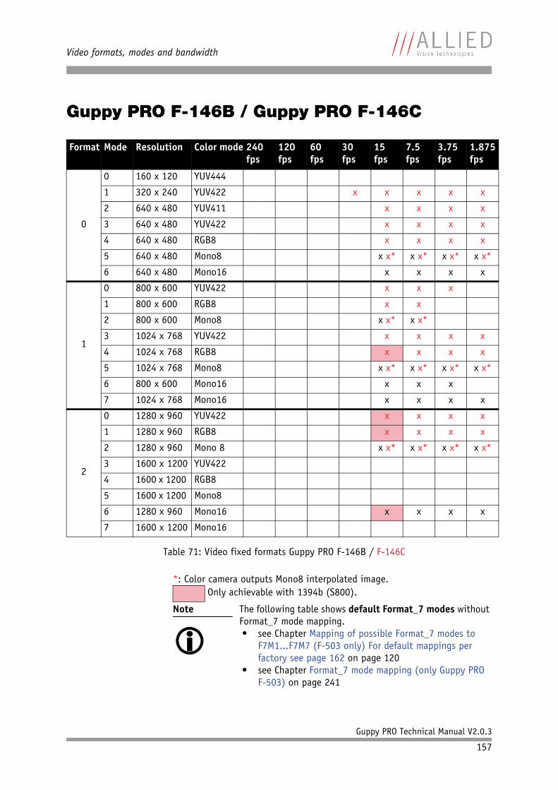
Video formats, modes and bandwidth
Guppy PRO Technical Manual V2.0.3
157
Guppy PRO F-146B / Guppy PRO F-146C
*: Color camera outputs Mono8 interpolated image.
Format Mode Resolution Color mode 240 fps
120 fps
60 fps
30 fps
15 fps
7.5 fps
3.75 fps
1.875 fps
0
0 160 x 120 YUV444
1 320 x 240 YUV422 x x x x x
2 640 x 480 YUV411 x x x x
3 640 x 480 YUV422 x x x x
4 640 x 480 RGB8 x x x x
5 640 x 480 Mono8 x x* x x* x x* x x*
6 640 x 480 Mono16 x x x x
1
0 800 x 600 YUV422 x x x
1 800 x 600 RGB8 x x
2 800 x 600 Mono8 x x* x x*
3 1024 x 768 YUV422 x x x x
4 1024 x 768 RGB8 x x x x
5 1024 x 768 Mono8 x x* x x* x x* x x*
6 800 x 600 Mono16 x x x
7 1024 x 768 Mono16 x x x x
2
0 1280 x 960 YUV422 x x x x
1 1280 x 960 RGB8 x x x x
2 1280 x 960 Mono 8 x x* x x* x x* x x*
3 1600 x 1200 YUV422
4 1600 x 1200 RGB8
5 1600 x 1200 Mono8
6 1280 x 960 Mono16 x x x x
7 1600 x 1200 Mono16
Table 71: Video fixed formats Guppy PRO F-146B / F-146C
Only achievable with 1394b (S800).
Note
The following table shows default Format_7 modes without Format_7 mode mapping.• see Chapter Mapping of possible Format_7 modes to
F7M1...F7M7 (F-503 only) For default mappings per factory see page 162 on page 120
• see Chapter Format_7 mode mapping (only Guppy PRO F-503) on page 241
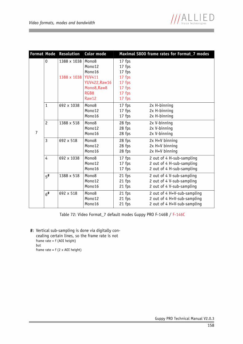
Video formats, modes and bandwidth
Guppy PRO Technical Manual V2.0.3
158
Format Mode Resolution Color mode Maximal S800 frame rates for Format_7 modes
7
0 1388 x 1038
1388 x 1038
Mono8Mono12Mono16YUV411YUV422,Raw16Mono8,Raw8RGB8Raw12
17 fps17 fps17 fps17 fps17 fps17 fps17 fps17 fps
1 692 x 1038 Mono8Mono12Mono16
17 fps 2x H-binning17 fps 2x H-binning17 fps 2x H-binning
2 1388 x 518 Mono8Mono12Mono16
28 fps 2x V-binning28 fps 2x V-binning28 fps 2x V-binning
3 692 x 518 Mono8Mono12Mono16
28 fps 2x H+V binning28 fps 2x H+V binning28 fps 2x H+V binning
4 692 x 1038
Mono8Mono12Mono16
17 fps 2 out of 4 H-sub-sampling17 fps 2 out of 4 H-sub-sampling17 fps 2 out of 4 H-sub-sampling
5# 1388 x 518
Mono8Mono12Mono16
21 fps 2 out of 4 V-sub-sampling21 fps 2 out of 4 V-sub-sampling21 fps 2 out of 4 V-sub-sampling
6# 692 x 518
Mono8Mono12Mono16
21 fps 2 out of 4 H+V-sub-sampling21 fps 2 out of 4 H+V-sub-sampling21 fps 2 out of 4 H+V-sub-sampling
Table 72: Video Format_7 default modes Guppy PRO F-146B / F-146C
#: Vertical sub-sampling is done via digitally con-cealing certain lines, so the frame rate is notframe rate = f (AOI height)butframe rate = f (2 x AOI height)
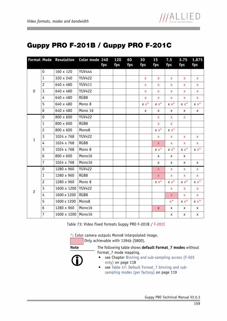
Video formats, modes and bandwidth
Guppy PRO Technical Manual V2.0.3
159
Guppy PRO F-201B / Guppy PRO F-201C
*: Color camera outputs Mono8 interpolated image.
Format Mode Resolution Color mode 240 fps
120 fps
60 fps
30 fps
15 fps
7.5 fps
3.75 fps
1.875 fps
0
0 160 x 120 YUV444
1 320 x 240 YUV422 x x x x x
2 640 x 480 YUV411 x x x x x
3 640 x 480 YUV422 x x x x x
4 640 x 480 RGB8 x x x x x
5 640 x 480 Mono 8 x x* x x* x x* x x* x x*
6 640 x 480 Mono 16 x x x x x
1
0 800 x 600 YUV422 x x x
1 800 x 600 RGB8 x x
2 800 x 600 Mono8 x x* x x*
3 1024 x 768 YUV422 x x x x
4 1024 x 768 RGB8 x x x x
5 1024 x 768 Mono 8 x x* x x* x x* x x*
6 800 x 600 Mono16 x x x
7 1024 x 768 Mono16 x x x x
2
0 1280 x 960 YUV422 x x x x
1 1280 x 960 RGB8 x x x x
2 1280 x 960 Mono 8 x x* x x* x x* x x*
3 1600 x 1200 YUV422 x x x
4 1600 x 1200 RGB8 x x x
5 1600 x 1200 Mono8 x* x x* x x*
6 1280 x 960 Mono16 x x x x
7 1600 x 1200 Mono16 x x x
Table 73: Video fixed formats Guppy PRO F-201B / F-201C
Only achievable with 1394b (S800).
Note
The following table shows default Format_7 modes without Format_7 mode mapping.• see Chapter Binning and sub-sampling access (F-503
only) on page 118• see Table 47: Default Format_7 binning and sub-
sampling modes (per factory) on page 119
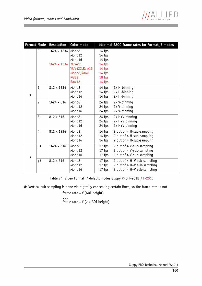
Video formats, modes and bandwidth
Guppy PRO Technical Manual V2.0.3
160
#: Vertical sub-sampling is done via digitally concealing certain lines, so the frame rate is not
frame rate = f (AOI height)butframe rate = f (2 x AOI height)
Format Mode Resolution Color mode Maximal S800 frame rates for Format_7 modes
7
0 1624 x 1234
1624 x 1234
Mono8Mono12Mono16YUV411YUV422,Raw16Mono8,Raw8RGB8Raw12
14 fps14 fps14 fps14 fps14 fps14 fps10 fps14 fps
1 812 x 1234
Mono8Mono12Mono16
14 fps 2x H-binning14 fps 2x H-binning14 fps 2x H-binning
2 1624 x 616
Mono8Mono12Mono16
24 fps 2x V-binning24 fps 2x V-binning24 fps 2x V-binning
3 812 x 616
Mono8Mono12Mono16
24 fps 2x H+V binning24 fps 2x H+V binning24 fps 2x H+V binning
4 812 x 1234
Mono8Mono12Mono16
14 fps 2 out of 4 H-sub-sampling14 fps 2 out of 4 H-sub-sampling14 fps 2 out of 4 H-sub-sampling
7
5# 1624 x 616
Mono8Mono12Mono16
17 fps 2 out of 4 V-sub-sampling17 fps 2 out of 4 V-sub-sampling17 fps 2 out of 4 V-sub-sampling
6# 812 x 616
Mono8Mono12Mono16
17 fps 2 out of 4 H+V sub-sampling17 fps 2 out of 4 H+V sub-sampling17 fps 2 out of 4 H+V sub-sampling
Table 74: Video Format_7 default modes Guppy PRO F-201B / F-201C
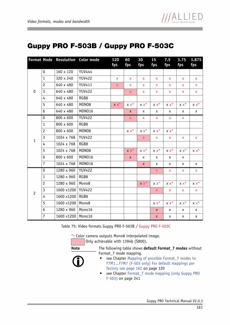
Video formats, modes and bandwidth
Guppy PRO Technical Manual V2.0.3
161
Guppy PRO F-503B / Guppy PRO F-503C
*: Color camera outputs Mono8 interpolated image.
Format Mode Resolution Color mode 120fps
60fps
30fps
15fps
7.5fps
3.75fps
1.875 fps
0
0 160 x 120 YUV444
1 320 x 240 YUV422 x x x x x x x
2 640 x 480 YUV411 x x x x x x x
3 640 x 480 YUV422 x x x x x x
4 640 x 480 RGB8
5 640 x 480 MONO8 x x* x x* x x* x x* x x* x x* x x*
6 640 x 480 MONO16 x x x x x x
1
0 800 x 600 YUV422 x x x x x
1 800 x 600 RGB8
2 800 x 600 MONO8 x x* x x* x x* x x*
3 1024 x 768 YUV422 x x x x x
4 1024 x 768 RGB8
5 1024 x 768 MONO8 x x* x x* x x* x x* x x* x x*
6 800 x 600 MONO16 x x x x x
7 1024 x 768 MONO16 x x x x x
2
0 1280 x 960 YUV422 x x x x
1 1280 x 960 RGB8
2 1280 x 960 Mono8 x x* x x* x x* x x* x x*
3 1600 x1200 YUV422 x x x x
4 1600 x1200 RGB8
5 1600 x1200 Mono8 x x* x x* x x* x x*
6 1280 x 960 Mono16 x x x x
7 1600 x1200 Mono16 x x x x
Table 75: Video formats Guppy PRO F-503B / Guppy PRO F-503C
Only achievable with 1394b (S800).
Note
The following table shows default Format_7 modes without Format_7 mode mapping.• see Chapter Mapping of possible Format_7 modes to
F7M1...F7M7 (F-503 only) For default mappings per factory see page 162 on page 120
• see Chapter Format_7 mode mapping (only Guppy PRO F-503) on page 241
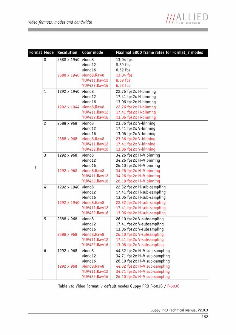
Video formats, modes and bandwidth
Guppy PRO Technical Manual V2.0.3
162
Format Mode Resolution Color mode Maximal S800 frame rates for Format_7 modes
7
0 2588 x 1940
2588 x 1940
Mono8Mono12Mono16Mono8,Raw8YUV411,Raw12YUV422,Raw16
13.04 fps8.69 fps6.52 fps13.04 fps8.69 fps6.52 fps
1 1292 x 1940
1292 x 1944
Mono8Mono12Mono16Mono8,Raw8YUV411,Raw12YUV422,Raw16
22.76 fps2x H-binning17.41 fps2x H-binning13.06 fps2x H-binning22.76 fps2x H-binning17.41 fps2x H-binning13.06 fps2x H-binning
2 2588 x 968
2588 x 968
Mono8Mono12Mono16Mono8,Raw8YUV411,Raw12YUV422,Raw16
23.36 fps2x V-binning17.41 fps2x V-binning13.06 fps2x V-binning23.36 fps2x V-binning17.41 fps2x V-binning13.06 fps2x V-binning
3 1292 x 968
1292 x 968
Mono8Mono12Mono16Mono8,Raw8YUV411,Raw12YUV422,Raw16
34.26 fps2x H+V binning34.26 fps2x H+V binning26.10 fps2x H+V binning34.26 fps2x H+V binning34.26 fps2x H+V binning26.10 fps2x H+V binning
4 1292 x 1940
1292 x 1940
Mono8Mono12Mono16Mono8,Raw8YUV411,Raw12YUV422,Raw16
22.32 fps2x H-sub-sampling17.41 fps2x H-sub-sampling13.06 fps2x H-sub-sampling22.32 fps2x H-sub-sampling17.41 fps2x H-sub-sampling13.06 fps2x H-sub-sampling
5 2588 x 968
2588 x 968
Mono8Mono12Mono16Mono8,Raw8YUV411,Raw12YUV422,Raw16
26.10 fps2x V-subsampling17.41 fps2x V-subsampling13.06 fps2x V-subsampling26.10 fps2x V-subsampling17.41 fps2x V-subsampling13.06 fps2x V-subsampling
6 1292 x 968
1292 x 968
Mono8Mono12Mono16Mono8,Raw8YUV411,Raw12YUV422,Raw16
44.32 fps2x H+V sub-sampling34.71 fps2x H+V sub-sampling26.10 fps2x H+V sub-sampling44.32 fps2x H+V sub-sampling34.71 fps2x H+V sub-sampling26.10 fps2x H+V sub-sampling
Table 76: Video Format_7 default modes Guppy PRO F-503B / F-503C
Video formats, modes and bandwidth
Guppy PRO Technical Manual V2.0.3
163
Area of interest (AOI)
The camera’s image sensor has a defined resolution. This indicates the max-imum number of lines and pixels per line that the recorded image may have.
However, often only a certain section of the entire image is of interest. The amount of data to be transferred can be decreased by limiting the image to a section when reading it out from the camera. At a lower vertical resolution the sensor can be read out faster and thus the frame rate is increased.
While the size of the image read out for most other video formats and modes is fixed by the IIDC specification, thereby determining the highest possible frame rate, in Format_7 mode the user can set the upper left corner and width and height of the section (area of interest = AOI) he is interested in to determine the size and thus the highest possible frame rate.
Setting the AOI is done in the IMAGE_POSITION and IMAGE_SIZE registers.
AF_AREA_POSITION and AF_AREA_SIZE contain in the respective bits values for the column and line of the upper left corner and values for the width and height.
Note
The setting of AOIs is supported only in video Format_7.
Note
Pay attention to the increments entering in the UNIT_SIZE_INQ and UNIT_POSITION_INQ registers when con-figuring IMAGE_POSITION and IMAGE_SIZE.
Note
For more information see Table 108: Format_7 control and status register on page 213.
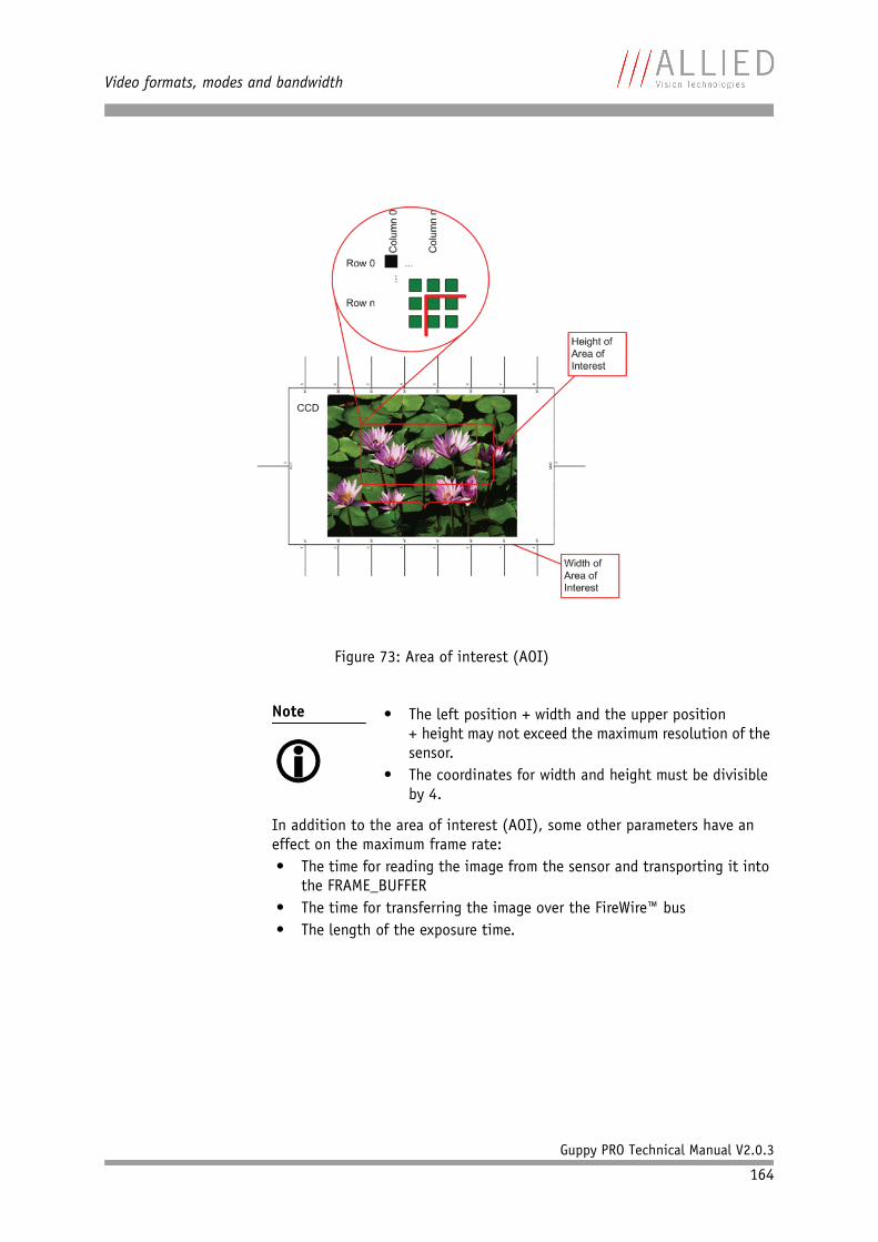
Video formats, modes and bandwidth
Guppy PRO Technical Manual V2.0.3
164
In addition to the area of interest (AOI), some other parameters have an effect on the maximum frame rate:• The time for reading the image from the sensor and transporting it into
the FRAME_BUFFER• The time for transferring the image over the FireWire™ bus• The length of the exposure time.
Figure 73: Area of interest (AOI)
Note
• The left position + width and the upper position
+ height may not exceed the maximum resolution of the sensor.
• The coordinates for width and height must be divisible by 4.
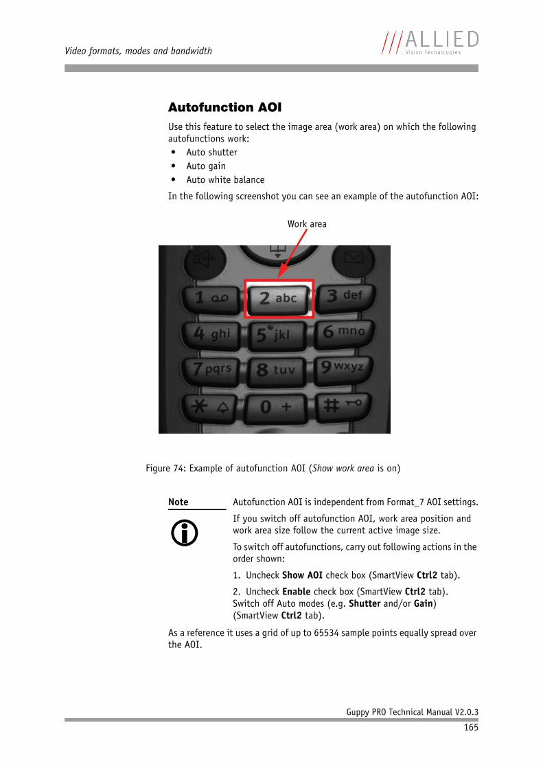
Video formats, modes and bandwidth
Guppy PRO Technical Manual V2.0.3
165
Autofunction AOIUse this feature to select the image area (work area) on which the following autofunctions work:• Auto shutter• Auto gain• Auto white balance
In the following screenshot you can see an example of the autofunction AOI:
As a reference it uses a grid of up to 65534 sample points equally spread over the AOI.
Figure 74: Example of autofunction AOI (Show work area is on)
Note
Autofunction AOI is independent from Format_7 AOI settings.
If you switch off autofunction AOI, work area position and work area size follow the current active image size.
To switch off autofunctions, carry out following actions in the order shown:
1. Uncheck Show AOI check box (SmartView Ctrl2 tab).
2. Uncheck Enable check box (SmartView Ctrl2 tab).Switch off Auto modes (e.g. Shutter and/or Gain) (SmartView Ctrl2 tab).
Work area
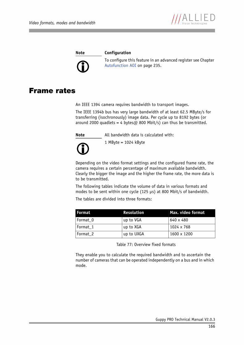
Video formats, modes and bandwidth
Guppy PRO Technical Manual V2.0.3
166
Frame rates
An IEEE 1394 camera requires bandwidth to transport images.
The IEEE 1394b bus has very large bandwidth of at least 62.5 MByte/s for transferring (isochronously) image data. Per cycle up to 8192 bytes (or around 2000 quadlets = 4 bytes@ 800 Mbit/s) can thus be transmitted.
Depending on the video format settings and the configured frame rate, the camera requires a certain percentage of maximum available bandwidth. Clearly the bigger the image and the higher the frame rate, the more data is to be transmitted.
The following tables indicate the volume of data in various formats and modes to be sent within one cycle (125 µs) at 800 Mbit/s of bandwidth.
The tables are divided into three formats:
They enable you to calculate the required bandwidth and to ascertain the number of cameras that can be operated independently on a bus and in which mode.
Note
Configuration
To configure this feature in an advanced register see Chapter Autofunction AOI on page 235.
Note
All bandwidth data is calculated with:
1 MByte = 1024 kByte
Format Resolution Max. video format
Format_0 up to VGA 640 x 480
Format_1 up to XGA 1024 x 768
Format_2 up to UXGA 1600 x 1200
Table 77: Overview fixed formats
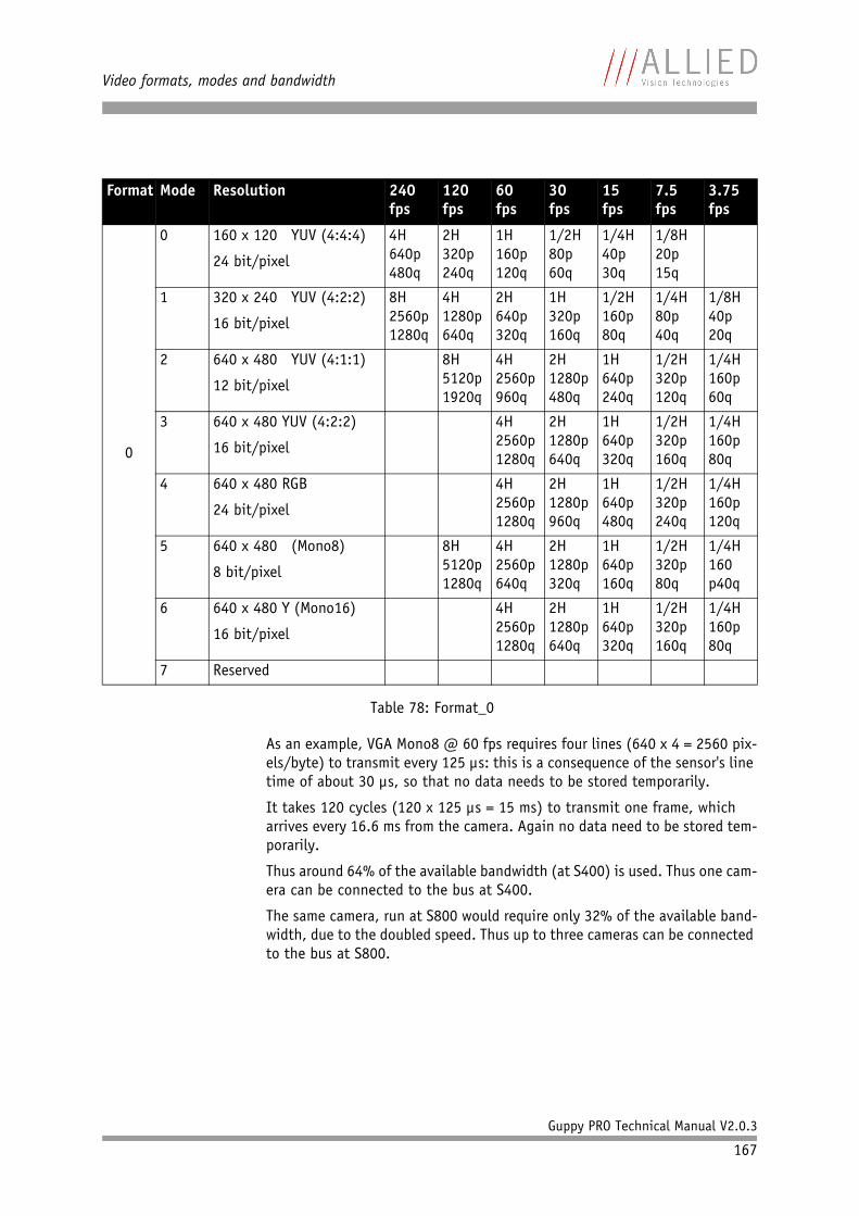
Video formats, modes and bandwidth
Guppy PRO Technical Manual V2.0.3
167
As an example, VGA Mono8 @ 60 fps requires four lines (640 x 4 = 2560 pix-els/byte) to transmit every 125 µs: this is a consequence of the sensor's line time of about 30 µs, so that no data needs to be stored temporarily.
It takes 120 cycles (120 x 125 µs = 15 ms) to transmit one frame, which arrives every 16.6 ms from the camera. Again no data need to be stored tem-porarily.
Thus around 64% of the available bandwidth (at S400) is used. Thus one cam-era can be connected to the bus at S400.
The same camera, run at S800 would require only 32% of the available band-width, due to the doubled speed. Thus up to three cameras can be connected to the bus at S800.
Format Mode Resolution 240fps
120fps
60fps
30fps
15fps
7.5fps
3.75fps
0
0 160 x 120 YUV (4:4:4)
24 bit/pixel
4H640p480q
2H320p240q
1H160p120q
1/2H80p60q
1/4H40p30q
1/8H20p15q
1 320 x 240 YUV (4:2:2)
16 bit/pixel
8H2560p1280q
4H1280p640q
2H640p320q
1H320p160q
1/2H160p80q
1/4H80p40q
1/8H40p20q
2 640 x 480 YUV (4:1:1)
12 bit/pixel
8H5120p1920q
4H2560p960q
2H1280p480q
1H640p240q
1/2H320p120q
1/4H160p60q
3 640 x 480 YUV (4:2:2)
16 bit/pixel
4H2560p1280q
2H1280p640q
1H640p320q
1/2H320p160q
1/4H160p80q
4 640 x 480 RGB
24 bit/pixel
4H2560p1280q
2H1280p960q
1H640p480q
1/2H320p240q
1/4H160p120q
5 640 x 480 (Mono8)
8 bit/pixel
8H5120p1280q
4H2560p640q
2H1280p320q
1H640p160q
1/2H320p80q
1/4H160p40q
6 640 x 480 Y (Mono16)
16 bit/pixel
4H2560p1280q
2H1280p640q
1H640p320q
1/2H320p160q
1/4H160p80q
7 Reserved
Table 78: Format_0
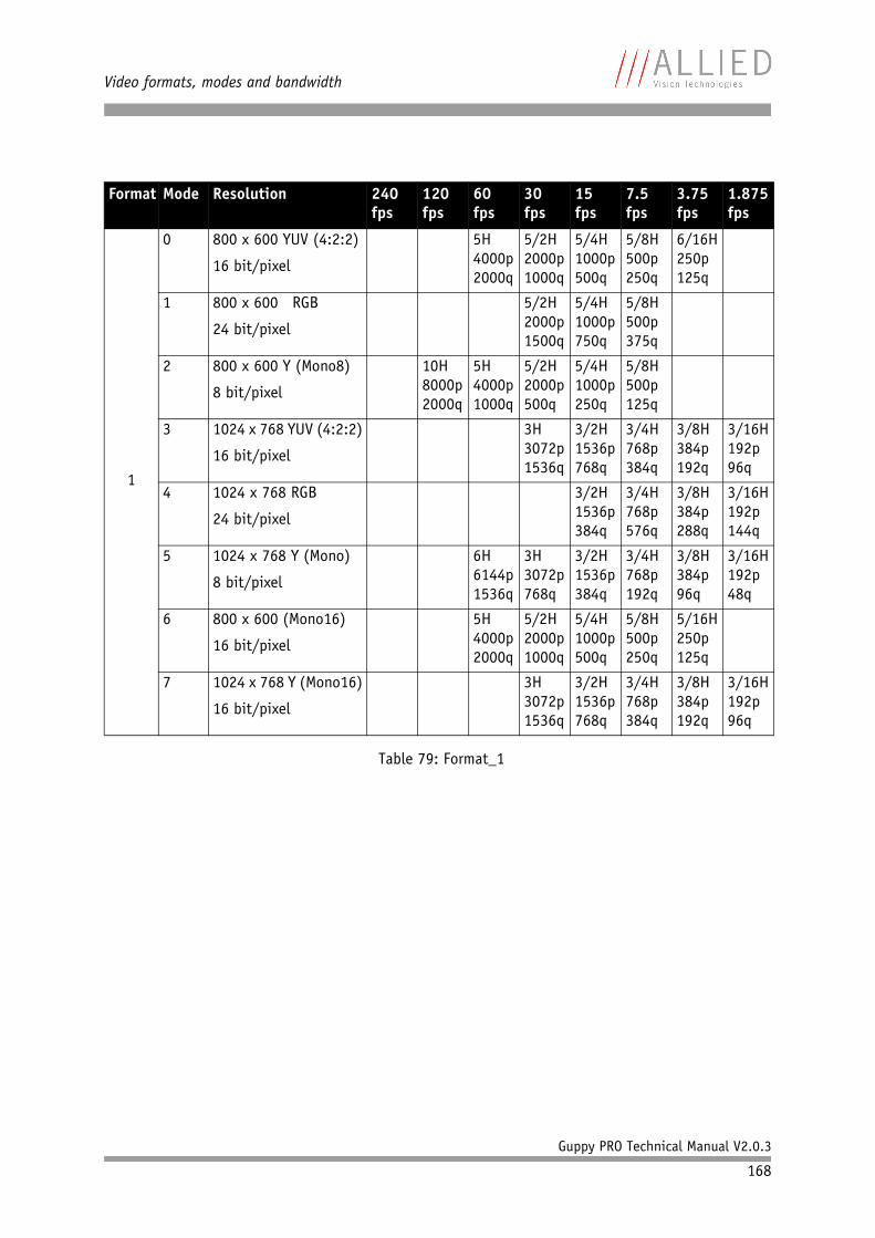
Video formats, modes and bandwidth
Guppy PRO Technical Manual V2.0.3
168
Format Mode Resolution 240 fps
120 fps
60 fps
30 fps
15 fps
7.5 fps
3.75 fps
1.875 fps
1
0 800 x 600 YUV (4:2:2)
16 bit/pixel
5H4000p2000q
5/2H 2000p 1000q
5/4H 1000p 500q
5/8H 500p 250q
6/16H 250p 125q
1 800 x 600 RGB
24 bit/pixel
5/2H2000p1500q
5/4H 1000p 750q
5/8H 500p 375q
2 800 x 600 Y (Mono8)
8 bit/pixel
10H8000p2000q
5H 4000p 1000q
5/2H 2000p 500q
5/4H 1000p 250q
5/8H 500p 125q
3 1024 x 768 YUV (4:2:2)
16 bit/pixel
3H3072p1536q
3/2H 1536p 768q
3/4H 768p 384q
3/8H 384p 192q
3/16H 192p 96q
4 1024 x 768 RGB
24 bit/pixel
3/2H1536p384q
3/4H 768p 576q
3/8H 384p 288q
3/16H 192p 144q
5 1024 x 768 Y (Mono)
8 bit/pixel
6H6144p1536q
3H 3072p 768q
3/2H 1536p 384q
3/4H 768p 192q
3/8H 384p 96q
3/16H 192p 48q
6 800 x 600 (Mono16)
16 bit/pixel
5H4000p2000q
5/2H 2000p 1000q
5/4H 1000p 500q
5/8H 500p 250q
5/16H 250p 125q
7 1024 x 768 Y (Mono16)
16 bit/pixel
3H3072p1536q
3/2H 1536p 768q
3/4H 768p 384q
3/8H 384p 192q
3/16H 192p 96q
Table 79: Format_1
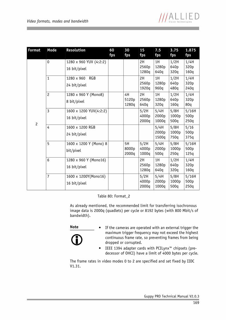
Video formats, modes and bandwidth
Guppy PRO Technical Manual V2.0.3
169
As already mentioned, the recommended limit for transferring isochronous image data is 2000q (quadlets) per cycle or 8192 bytes (with 800 Mbit/s of bandwidth).
The frame rates in video modes 0 to 2 are specified and set fixed by IIDC V1.31.
Format Mode Resolution 60 fps
30 fps
15 fps
7.5 fps
3.75 fps
1.875 fps
2
0 1280 x 960 YUV (4:2:2)
16 bit/pixel
2H2560p1280q
1H 1280p 640q
1/2H 640p 320q
1/4H 320p 160q
1 1280 x 960 RGB
24 bit/pixel
2H2560p1920q
1H 1280p 960q
1/2H 640p 480q
1/4H 320p 240q
2 1280 x 960 Y (Mono8)
8 bit/pixel
4H5120p1280q
2H 2560p 640q
1H 1280p 320q
1/2H 640p 160q
1/4H 320p 80q
3 1600 x 1200 YUV(4:2:2)
16 bit/pixel
5/2H4000p2000q
5/4H 2000p 1000q
5/8H 1000p 500q
5/16H 500p 250q
4 1600 x 1200 RGB
24 bit/pixel
5/4H2000p1500q
5/8H 1000p 750q
5/16 500p 375q
5 1600 x 1200 Y (Mono) 8
bit/pixel
5H8000p2000q
5/2H 4000p 1000q
5/4H 2000p 500q
5/8H 1000p 250q
5/16H 500p 125q
6 1280 x 960 Y (Mono16)
16 bit/pixel
2H2560p1280q
1H 1280p 640q
1/2H 640p 320q
1/4H 320p 160q
7 1600 x 1200Y(Mono16)
16 bit/pixel
5/2H4000p2000q
5/4H 2000p 1000q
5/8H 1000p 500q
5/16H 500p 250q
Table 80: Format_2
Note
• If the cameras are operated with an external trigger the
maximum trigger frequency may not exceed the highest continuous frame rate, so preventing frames from being dropped or corrupted.
• IEEE 1394 adapter cards with PCILynx™ chipsets (pre-decessor of OHCI) have a limit of 4000 bytes per cycle.
Video formats, modes and bandwidth
Guppy PRO Technical Manual V2.0.3
170
Frame rates Format_7In video Format_7 frame rates are no longer fixed.
Details are described in the next chapters:• Max. frame rate of CCD (theoretical formula)• Diagram of frame rates as function of AOI by constant width: the curves
describe RAW8, RAW12/YUV411, RAW16/YUV422, RGB8 and max. frame rate of CCD
• Table with max. frame rates as function of AOI by constant width
Note
• Different values apply for the different sensors.• Frame rates may be further limited by longer shutter
times and/or bandwidth limitation from the IEEE 1394 bus.
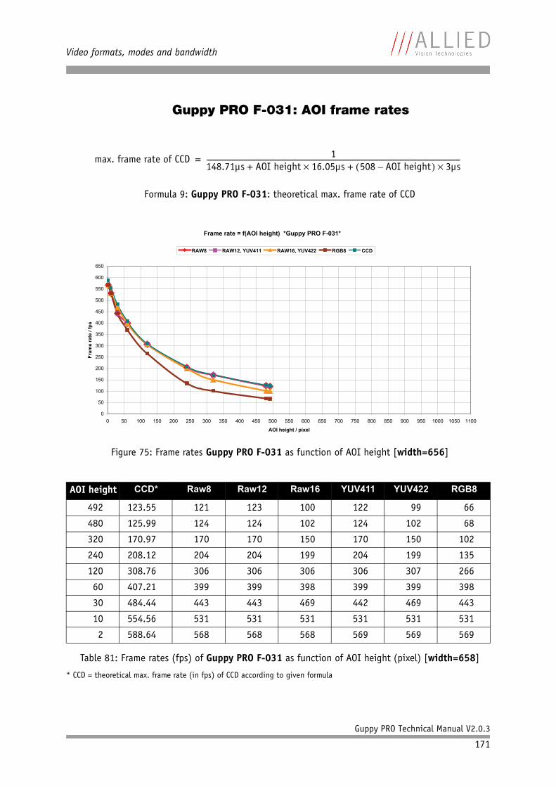
Video formats, modes and bandwidth
Guppy PRO Technical Manual V2.0.3
171
Guppy PRO F-031: AOI frame rates
* CCD = theoretical max. frame rate (in fps) of CCD according to given formula
Formula 9: Guppy PRO F-031: theoretical max. frame rate of CCD
Figure 75: Frame rates Guppy PRO F-031 as function of AOI height [width=656]
AOI height CCD* Raw8 Raw12 Raw16 YUV411 YUV422 RGB8
492 123.55 121 123 100 122 99 66
480 125.99 124 124 102 124 102 68
320 170.97 170 170 150 170 150 102
240 208.12 204 204 199 204 199 135
120 308.76 306 306 306 306 307 266
60 407.21 399 399 398 399 399 398
30 484.44 443 443 469 442 469 443
10 554.56 531 531 531 531 531 531
2 588.64 568 568 568 569 569 569
Table 81: Frame rates (fps) of Guppy PRO F-031 as function of AOI height (pixel) [width=658]
max. frame rate of CCD 1148.71µs AOI height 16.05µs 508 AOI height– 3µs+ +----------------------------------------------------------------------------------------------------------------------------------------------------=
Frame rate = f(AOI height) *Guppy PRO F-031*
0
50
100
150
200
250
300
350
400
450
500
550
600
650
0 50 100 150 200 250 300 350 400 450 500 550 600 650 700 750 800 850 900 950 1000 1050 1100
AOI height / pixel
Fram
e ra
te /
fps
RAW8 RAW12, YUV411 RAW16, YUV422 RGB8 CCD
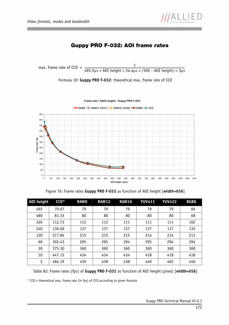
Video formats, modes and bandwidth
Guppy PRO Technical Manual V2.0.3
172
Guppy PRO F-032: AOI frame rates
* CCD = theoretical max. frame rate (in fps) of CCD according to given formula
Formula 10: Guppy PRO F-032: theoretical max. frame rate of CCD
Figure 76: Frame rates Guppy PRO F-032 as function of AOI height [width=656]
AOI height CCD* RAW8 RAW12 RAW16 YUV411 YUV422 RGB8
492 79.67 79 79 79 79 79 66
480 81.33 80 80 80 80 80 68
320 112.73 112 112 111 111 111 102
240 139.69 137 137 137 137 137 135
120 217.84 215 215 215 214 214 213
60 302.43 295 295 294 295 294 294
30 375.30 360 360 360 360 360 360
10 447.12 434 434 434 418 418 418
2 484.19 439 438 438 440 465 440
Table 82: Frame rates (fps) of Guppy PRO F-032 as function of AOI height (pixel) [width=656]
max. frame rate of CCD 1495.5µs AOI height 24.4µs 509 AOI height– 3µs+ +----------------------------------------------------------------------------------------------------------------------------------------------=
Frame rate = f(AOI height) *Guppy PRO F-032*
0
50
100
150
200
250
300
350
400
450
500
550
0 50 100 150 200 250 300 350 400 450 500 550 600 650 700 750 800 850 900 950 1000 1050 1100
AOI height / pixel
Fram
e ra
te /
fps
RAW8 RAW12, YUV411 RAW16, YUV422 RGB8 CCD
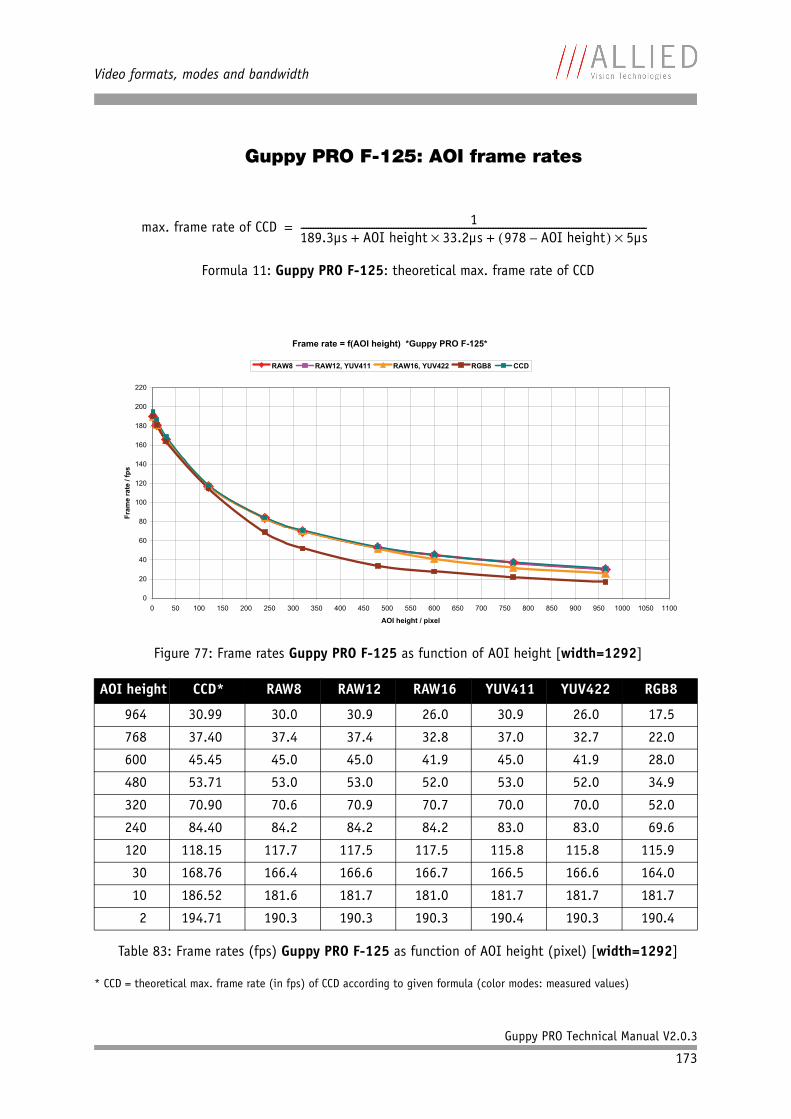
Video formats, modes and bandwidth
Guppy PRO Technical Manual V2.0.3
173
Guppy PRO F-125: AOI frame rates
* CCD = theoretical max. frame rate (in fps) of CCD according to given formula (color modes: measured values)
Formula 11: Guppy PRO F-125: theoretical max. frame rate of CCD
Figure 77: Frame rates Guppy PRO F-125 as function of AOI height [width=1292]
AOI height CCD* RAW8 RAW12 RAW16 YUV411 YUV422 RGB8
964 30.99 30.0 30.9 26.0 30.9 26.0 17.5
768 37.40 37.4 37.4 32.8 37.0 32.7 22.0
600 45.45 45.0 45.0 41.9 45.0 41.9 28.0
480 53.71 53.0 53.0 52.0 53.0 52.0 34.9
320 70.90 70.6 70.9 70.7 70.0 70.0 52.0
240 84.40 84.2 84.2 84.2 83.0 83.0 69.6
120 118.15 117.7 117.5 117.5 115.8 115.8 115.9
30 168.76 166.4 166.6 166.7 166.5 166.6 164.0
10 186.52 181.6 181.7 181.0 181.7 181.7 181.7
2 194.71 190.3 190.3 190.3 190.4 190.3 190.4
Table 83: Frame rates (fps) Guppy PRO F-125 as function of AOI height (pixel) [width=1292]
max. frame rate of CCD 1189.3µs AOI height 33.2µs 978 AOI height– 5µs+ +----------------------------------------------------------------------------------------------------------------------------------------------=
Frame rate = f(AOI height) *Guppy PRO F-125*
0
20
40
60
80
100
120
140
160
180
200
220
0 50 100 150 200 250 300 350 400 450 500 550 600 650 700 750 800 850 900 950 1000 1050 1100
AOI height / pixel
Fram
e ra
te /
fps
RAW8 RAW12, YUV411 RAW16, YUV422 RGB8 CCD
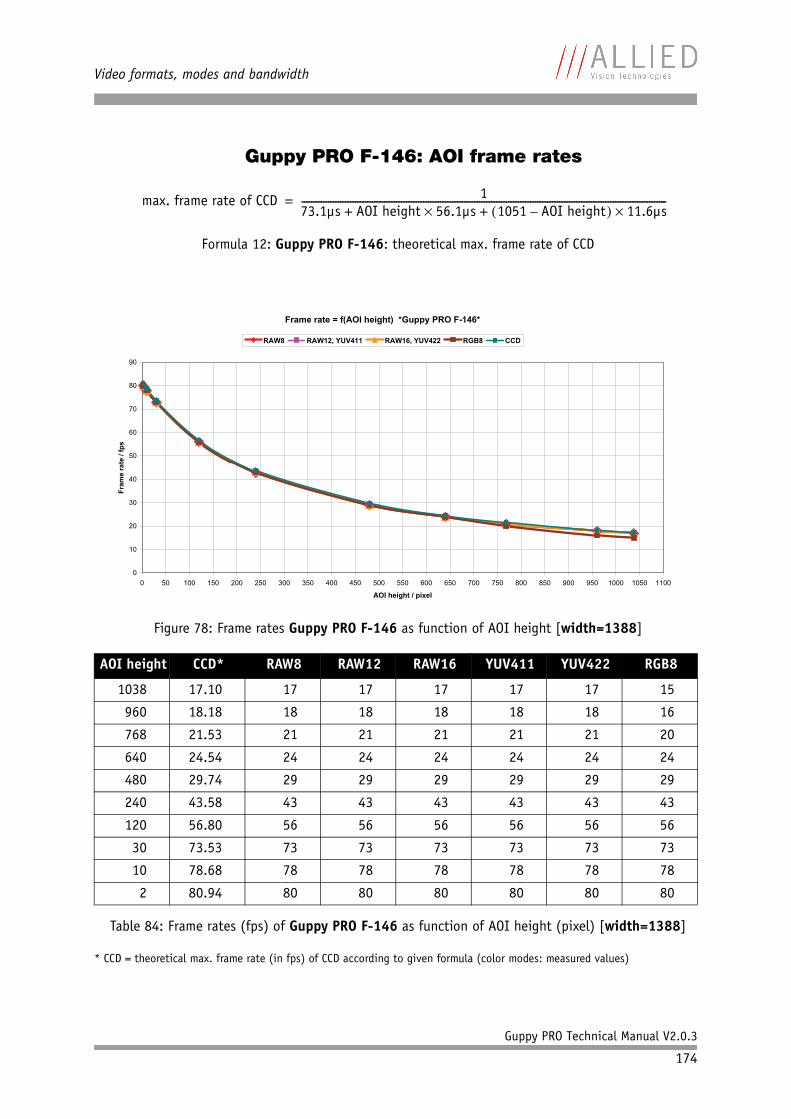
Video formats, modes and bandwidth
Guppy PRO Technical Manual V2.0.3
174
Guppy PRO F-146: AOI frame rates
* CCD = theoretical max. frame rate (in fps) of CCD according to given formula (color modes: measured values)
Formula 12: Guppy PRO F-146: theoretical max. frame rate of CCD
Figure 78: Frame rates Guppy PRO F-146 as function of AOI height [width=1388]
AOI height CCD* RAW8 RAW12 RAW16 YUV411 YUV422 RGB8
1038 17.10 17 17 17 17 17 15
960 18.18 18 18 18 18 18 16
768 21.53 21 21 21 21 21 20
640 24.54 24 24 24 24 24 24
480 29.74 29 29 29 29 29 29
240 43.58 43 43 43 43 43 43
120 56.80 56 56 56 56 56 56
30 73.53 73 73 73 73 73 73
10 78.68 78 78 78 78 78 78
2 80.94 80 80 80 80 80 80
Table 84: Frame rates (fps) of Guppy PRO F-146 as function of AOI height (pixel) [width=1388]
max. frame rate of CCD 173.1µs AOI height 56.1µs 1051 AOI height– 11.6µs+ +------------------------------------------------------------------------------------------------------------------------------------------------------=
Frame rate = f(AOI height) *Guppy PRO F-146*
0
10
20
30
40
50
60
70
80
90
0 50 100 150 200 250 300 350 400 450 500 550 600 650 700 750 800 850 900 950 1000 1050 1100
AOI height / pixel
Fram
e ra
te /
fps
RAW8 RAW12, YUV411 RAW16, YUV422 RGB8 CCD
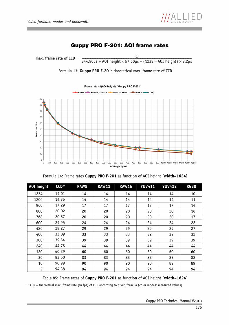
Video formats, modes and bandwidth
Guppy PRO Technical Manual V2.0.3
175
Guppy PRO F-201: AOI frame rates
* CCD = theoretical max. frame rate (in fps) of CCD according to given formula (color modes: measured values)
Formula 13: Guppy PRO F-201: theoretical max. frame rate of CCD
Formula 14: Frame rates Guppy PRO F-201 as function of AOI height [width=1624]
AOI height CCD* RAW8 RAW12 RAW16 YUV411 YUV422 RGB8
1234 14.01 14 14 14 14 14 101200 14.35 14 14 14 14 14 11960 17.29 17 17 17 17 17 14800 20.02 20 20 20 20 20 16768 20.67 20 20 20 20 20 17600 24.95 24 24 24 24 24 22480 29.27 29 29 29 29 29 27400 33.09 33 33 33 32 32 32300 39.54 39 39 39 39 39 39240 44.78 44 44 44 44 44 44120 60.29 60 60 60 60 60 6030 83.50 83 83 83 82 82 8210 90.99 90 90 90 90 89 892 94.38 94 94 94 94 94 94
Table 85: Frame rates of Guppy PRO F-201 as function of AOI height [width=1624]
max. frame rate of CCD 1344.90µs AOI height 57.50µs 1238 AOI height– 8.2µs+ +------------------------------------------------------------------------------------------------------------------------------------------------------------=
Frame rate = f(AOI height) *Guppy PRO F-201*
0
10
20
30
40
50
60
70
80
90
100
0 50 100 150 200 250 300 350 400 450 500 550 600 650 700 750 800 850 900 950 1000 1050 1100 1150 1200 1250
AOI height / pixel
Fram
e ra
te /
fps
RAW8 RAW12, YUV411 RAW16, YUV422 RGB8 CCD
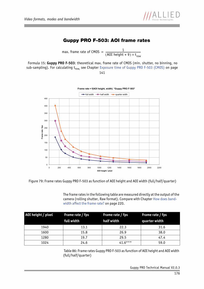
Video formats, modes and bandwidth
Guppy PRO Technical Manual V2.0.3
176
Guppy PRO F-503: AOI frame rates
The frame rates in the following table are measured directly at the output of the camera (rolling shutter, Raw format). Compare with Chapter How does band-width affect the frame rate? on page 220.
Formula 15: Guppy PRO F-503: theoretical max. frame rate of CMOS (min. shutter, no binning, no sub-sampling). For calculating trow, see Chapter Exposure time of Guppy PRO F-503 (CMOS) on page
141
Figure 79: Frame rates Guppy PRO F-503 as function of AOI height and AOI width (full/half/quarter)
AOI height / pixel Frame rate / fps
full width
Frame rate / fps
half width
Frame rate / fps
quarter width
1940 13.1 22.3 31.61600 15.8 26.9 38.01280 19.7 29.5 47.41024 24.6 41.6*** 59.0
Table 86: Frame rates Guppy PRO F-503 as function of AOI height and AOI width (full/half/quarter)
max. frame rate of CMOS 1AOI height + 9 trow
--------------------------------------------------------=
0
50
100
150
200
250
300
350
400
450
0 200 400 600 800 1000 1200 1400 1600 1800 2000 2200
Fram
e ra
te /
fps
AOI height / pixel
Frame rate = f(AOI height, width) *Guppy PRO F-503*
full width half width quarter width
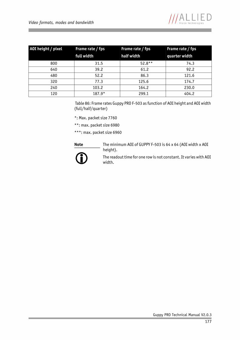
Video formats, modes and bandwidth
Guppy PRO Technical Manual V2.0.3
177
*: Max. packet size 7760
**: max. packet size 6980
***: max. packet size 6960
800 31.5 52.8** 74.3640 39.2 61.2 92.2480 52.2 86.3 121.6320 77.3 125.6 174.7240 103.2 164.2 230.0120 187.9* 299.1 404.2
Note
The minimum AOI of GUPPY F-503 is 64 x 64 (AOI width x AOI height).
The readout time for one row is not constant. It varies with AOI width.
AOI height / pixel Frame rate / fps
full width
Frame rate / fps
half width
Frame rate / fps
quarter width
Table 86: Frame rates Guppy PRO F-503 as function of AOI height and AOI width (full/half/quarter)

How does bandwidth affect the frame rate?
Guppy PRO Technical Manual V2.0.3
178
How does bandwidth affect the frame rate?
In some modes the IEEE 1394b bus limits the attainable frame rate. Accord-ing to the 1394b specification on isochronous transfer, the largest data pay-load size of 8192 bytes per 125 µs cycle is possible with bandwidth of 800 Mbit/s. In addition, there is a limitation, only a maximum number of 65535 (216 -1) packets per frame are allowed.
The following formula establishes the relationship between the required Byte_Per_Packet size and certain variables for the image. It is valid only for Format_7.
If the value for BYTE_PER_PACKET is greater than 8192 (the maximum data payload), the sought-after frame rate cannot be attained.
The attainable frame rate can be calculated using this formula:
(Provision: BYTE_PER_PACKET is divisible by 4):
Note
Certain cameras may offer, depending on their settings in combination with the use of AVT FirePackage higher packet sizes.
Consult your local dealer's support team, if you require addi-tional information on this feature.
Formula 16: Byte_per_Packet calculation (only Format_7)
Formula 17: Maximum frame rate calculation
BYTE_PER_PACKET frame rate AOI_WIDTH AOI_HEIGHT ByteDepth 125µs=
frame rateBYTE_PER_PACKET
AOI_WIDTH AOI_HEIGHT ByteDepth 125µs---------------------------------------------------------------------------------------------------------------------
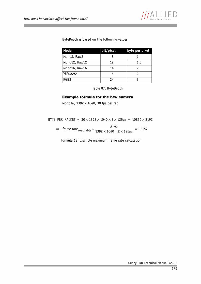
How does bandwidth affect the frame rate?
Guppy PRO Technical Manual V2.0.3
179
ByteDepth is based on the following values:
Example formula for the b/w camera
Mono16, 1392 x 1040, 30 fps desired
Mode bit/pixel byte per pixel
Mono8, Raw8 8 1
Mono12, Raw12 12 1.5
Mono16, Raw16 14 2
YUV4:2:2 16 2
RGB8 24 3
Table 87: ByteDepth
Formula 18: Example maximum frame rate calculation
BYTE_PER_PACKET 30 1392 1040 2 125µs 10856 8192= =
frame ratereachable8192
1392 1040 2 125µs------------------------------------------------------------ 22.64=
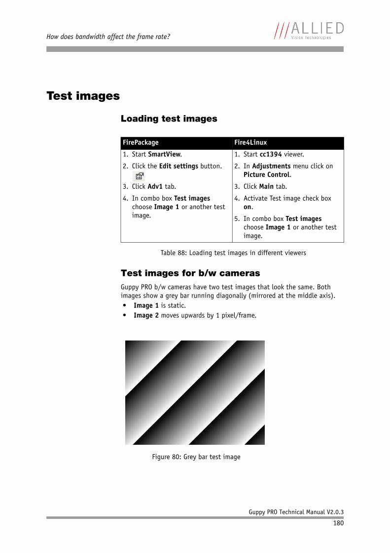
How does bandwidth affect the frame rate?
Guppy PRO Technical Manual V2.0.3
180
Test images
Loading test images
Test images for b/w camerasGuppy PRO b/w cameras have two test images that look the same. Both images show a grey bar running diagonally (mirrored at the middle axis).• Image 1 is static.• Image 2 moves upwards by 1 pixel/frame.
FirePackage Fire4Linux
1. Start SmartView.
2. Click the Edit settings button.
3. Click Adv1 tab.
4. In combo box Test images choose Image 1 or another test image.
1. Start cc1394 viewer.
2. In Adjustments menu click on Picture Control.
3. Click Main tab.
4. Activate Test image check box on.
5. In combo box Test images choose Image 1 or another test image.
Table 88: Loading test images in different viewers
Figure 80: Grey bar test image
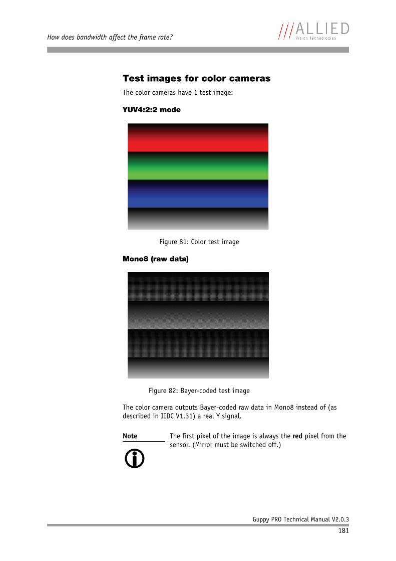
How does bandwidth affect the frame rate?
Guppy PRO Technical Manual V2.0.3
181
Test images for color camerasThe color cameras have 1 test image:
YUV4:2:2 mode
Mono8 (raw data)
The color camera outputs Bayer-coded raw data in Mono8 instead of (as described in IIDC V1.31) a real Y signal.
Figure 81: Color test image
Figure 82: Bayer-coded test image
Note
The first pixel of the image is always the red pixel from the sensor. (Mirror must be switched off.)
Configuration of the camera
Guppy PRO Technical Manual V2.0.3
182
Configuration of the camera
All camera settings are made by writing specific values into the correspond-ing registers.
This applies to:• values for general operating states such as video formats and modes,
exposure times, etc.• extended features of the camera that are turned on and off and con-
trolled via corresponding registers (so-called advanced registers).
Camera_Status_Register
The interoperability of cameras from different manufacturers is ensured by IIDC, formerly DCAM (Digital Camera Specification), published by the IEEE 1394 Trade Association.
IIDC is primarily concerned with setting memory addresses (e.g. CSR: Camera_Status_Register) and their meaning.
In principle all addresses in IEEE 1394 networks are 64 bits long.
The first 10 bits describe the Bus_Id, the next 6 bits the Node_Id.
Of the subsequent 48 bit, the first 16 bit are always FFFFh, leaving the description for the Camera_Status_Register in the last 32 bit.
If a CSR F0F00600h is mentioned below this means in full:
Bus_Id, Node_Id, FFFF F0F00600h
Writing and reading to and from the register can be done with programs such as FireView or by other programs developed using an API library (e.g. FirePackage).10Every register is 32 bit (big endian) and implemented as follows (MSB = Most Significant Bit; LSB = Least Significant Bit):
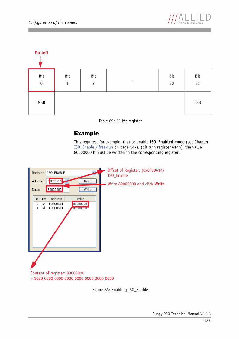
Configuration of the camera
Guppy PRO Technical Manual V2.0.3
183
ExampleThis requires, for example, that to enable ISO_Enabled mode (see Chapter ISO_Enable / free-run on page 147), (bit 0 in register 614h), the value 80000000 h must be written in the corresponding register.
Far left
Bit
0
Bit
1
Bit
2...
Bit
30
Bit
31
MSB LSB
Table 89: 32-bit register
Figure 83: Enabling ISO_Enable
Offset of Register: (0x0F00614)ISO_Enable
Write 80000000 and click Write
Content of register: 80000000= 1000 0000 0000 0000 0000 0000 0000 0000
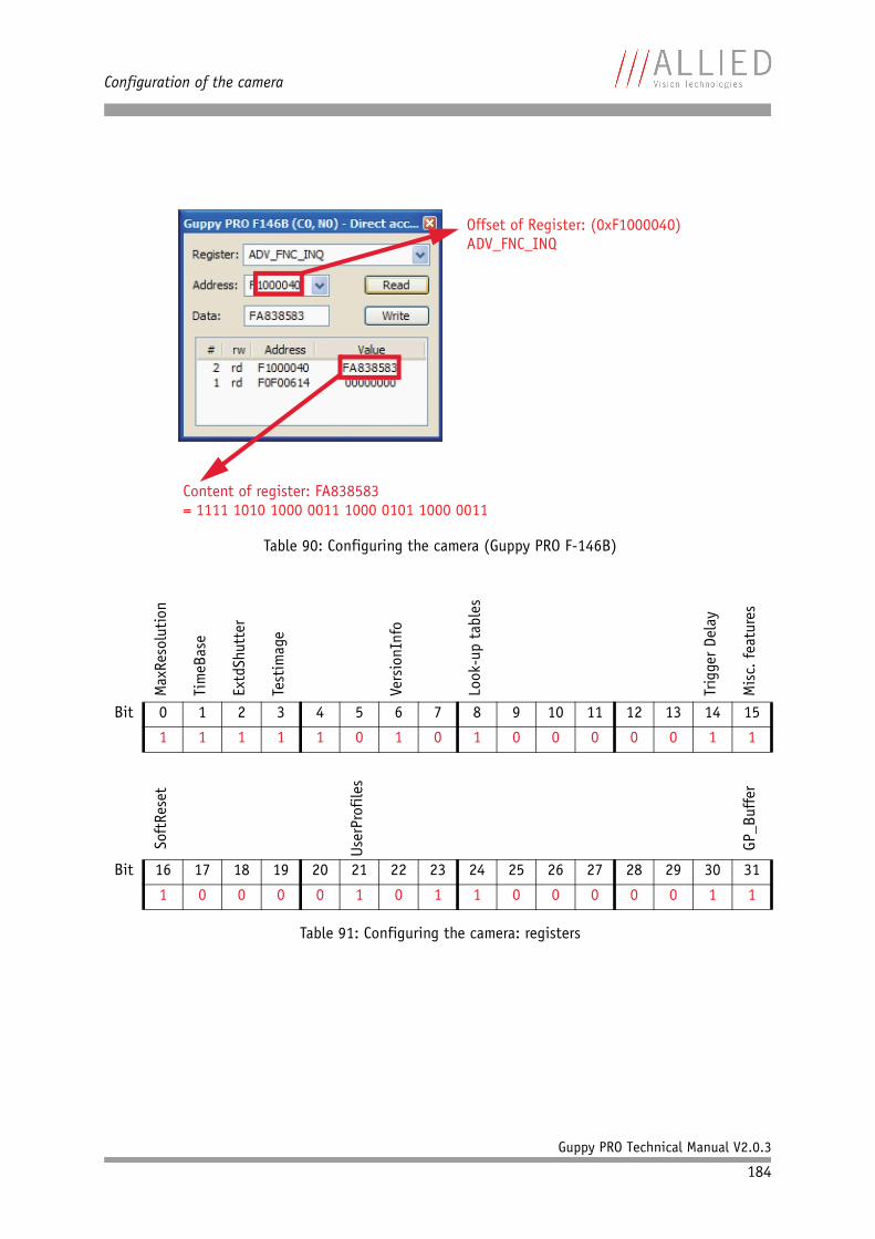
Configuration of the camera
Guppy PRO Technical Manual V2.0.3
184
Table 90: Configuring the camera (Guppy PRO F-146B)
Max
Reso
luti
on
Tim
eBas
e
Extd
Shut
ter
Test
imag
e
Vers
ionI
nfo
Look
-up
tabl
es
Trig
ger
Dela
y
Mis
c. f
eatu
res
Bit 0 1 2 3 4 5 6 7 8 9 10 11 12 13 14 15
1 1 1 1 1 0 1 0 1 0 0 0 0 0 1 1
Soft
Rese
t
User
Prof
iles
GP_B
uffe
r
Bit 16 17 18 19 20 21 22 23 24 25 26 27 28 29 30 31
1 0 0 0 0 1 0 1 1 0 0 0 0 0 1 1
Table 91: Configuring the camera: registers
Content of register: FA838583= 1111 1010 1000 0011 1000 0101 1000 0011
Offset of Register: (0xF1000040)ADV_FNC_INQ
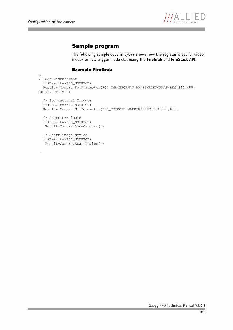
Configuration of the camera
Guppy PRO Technical Manual V2.0.3
185
Sample programThe following sample code in C/C++ shows how the register is set for video mode/format, trigger mode etc. using the FireGrab and FireStack API.
Example FireGrab…// Set Videoformat if(Result==FCE_NOERROR) Result= Camera.SetParameter(FGP_IMAGEFORMAT,MAKEIMAGEFORMAT(RES_640_480, CM_Y8, FR_15));
// Set external Trigger if(Result==FCE_NOERROR) Result= Camera.SetParameter(FGP_TRIGGER,MAKETRIGGER(1,0,0,0,0));
// Start DMA logic if(Result==FCE_NOERROR) Result=Camera.OpenCapture();
// Start image device if(Result==FCE_NOERROR) Result=Camera.StartDevice();
…
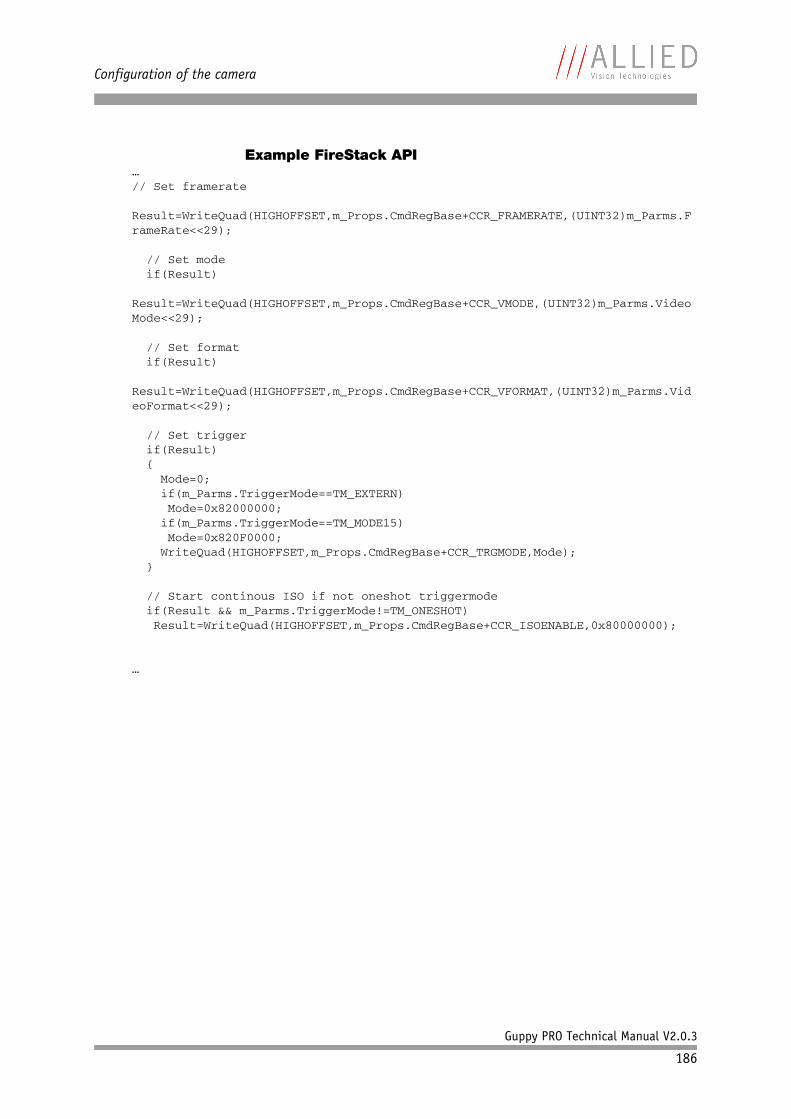
Configuration of the camera
Guppy PRO Technical Manual V2.0.3
186
Example FireStack API…// Set framerate Result=WriteQuad(HIGHOFFSET,m_Props.CmdRegBase+CCR_FRAMERATE,(UINT32)m_Parms.FrameRate<<29);
// Set mode if(Result) Result=WriteQuad(HIGHOFFSET,m_Props.CmdRegBase+CCR_VMODE,(UINT32)m_Parms.VideoMode<<29);
// Set format if(Result) Result=WriteQuad(HIGHOFFSET,m_Props.CmdRegBase+CCR_VFORMAT,(UINT32)m_Parms.VideoFormat<<29);
// Set trigger if(Result) { Mode=0; if(m_Parms.TriggerMode==TM_EXTERN) Mode=0x82000000; if(m_Parms.TriggerMode==TM_MODE15) Mode=0x820F0000; WriteQuad(HIGHOFFSET,m_Props.CmdRegBase+CCR_TRGMODE,Mode); }
// Start continous ISO if not oneshot triggermode if(Result && m_Parms.TriggerMode!=TM_ONESHOT) Result=WriteQuad(HIGHOFFSET,m_Props.CmdRegBase+CCR_ISOENABLE,0x80000000);
…
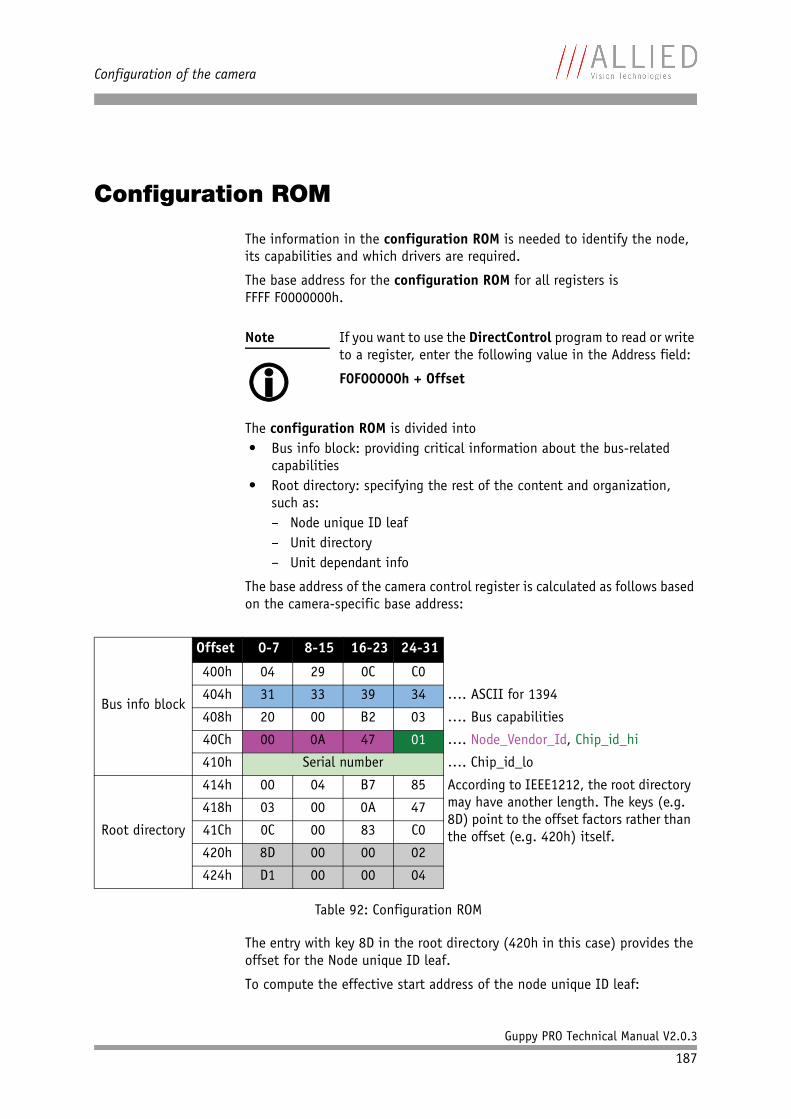
Configuration of the camera
Guppy PRO Technical Manual V2.0.3
187
Configuration ROM
The information in the configuration ROM is needed to identify the node, its capabilities and which drivers are required.
The base address for the configuration ROM for all registers is FFFF F0000000h.
The configuration ROM is divided into• Bus info block: providing critical information about the bus-related
capabilities• Root directory: specifying the rest of the content and organization,
such as:– Node unique ID leaf– Unit directory– Unit dependant info
The base address of the camera control register is calculated as follows based on the camera-specific base address:
The entry with key 8D in the root directory (420h in this case) provides the offset for the Node unique ID leaf.
To compute the effective start address of the node unique ID leaf:
Note
If you want to use the DirectControl program to read or write to a register, enter the following value in the Address field:
F0F00000h + Offset
Bus info block
Offset 0-7 8-15 16-23 24-31
400h 04 29 0C C0
404h 31 33 39 34 …. ASCII for 1394
408h 20 00 B2 03 …. Bus capabilities
40Ch 00 0A 47 01 …. Node_Vendor_Id, Chip_id_hi
410h Serial number …. Chip_id_lo
Root directory
414h 00 04 B7 85 According to IEEE1212, the root directory may have another length. The keys (e.g. 8D) point to the offset factors rather than the offset (e.g. 420h) itself.
418h 03 00 0A 47
41Ch 0C 00 83 C0
420h 8D 00 00 02
424h D1 00 00 04
Table 92: Configuration ROM
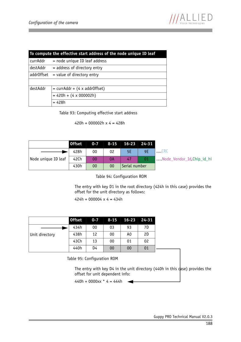
Configuration of the camera
Guppy PRO Technical Manual V2.0.3
188
420h + 000002h x 4 = 428h
The entry with key D1 in the root directory (424h in this case) provides the offset for the unit directory as follows:
424h + 000004 x 4 = 434h
The entry with key D4 in the unit directory (440h in this case) provides the offset for unit dependent info:
440h + 0000xx * 4 = 444h
To compute the effective start address of the node unique ID leaf
currAddr = node unique ID leaf address
destAddr = address of directory entry
addrOffset = value of directory entry
destAddr = currAddr + (4 x addrOffset)
= 420h + (4 x 000002h)
= 428h
Table 93: Computing effective start address
Offset 0-7 8-15 16-23 24-31
428h 00 02 5E 9E ....CRC
Node unique ID leaf 42Ch 00 0A 47 01 ….Node_Vendor_Id,Chip_id_hi
430h 00 00 Serial number
Table 94: Configuration ROM
Offset 0-7 8-15 16-23 24-31
Unit directory
434h 00 03 93 7D
438h 12 00 A0 2D
43Ch 13 00 01 02
440h D4 00 00 01
Table 95: Configuration ROM
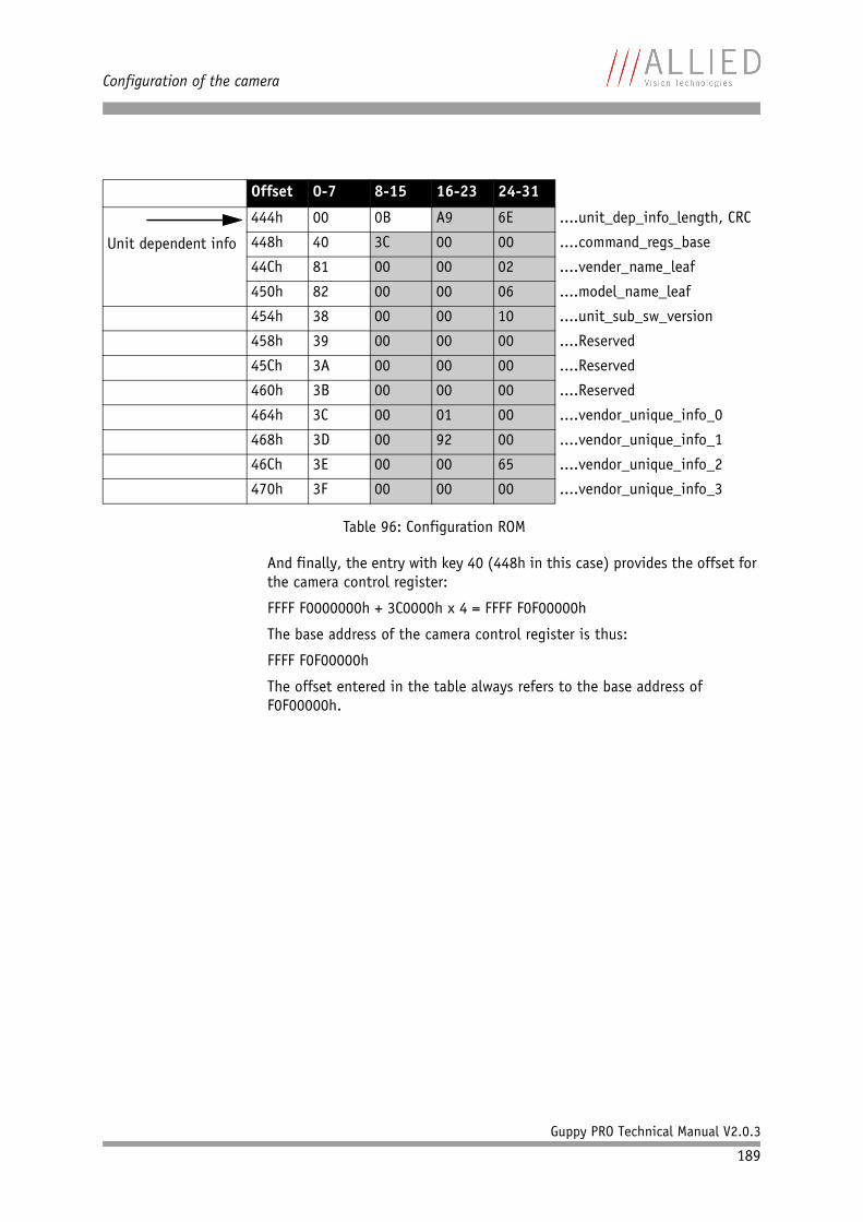
Configuration of the camera
Guppy PRO Technical Manual V2.0.3
189
And finally, the entry with key 40 (448h in this case) provides the offset for the camera control register:
FFFF F0000000h + 3C0000h x 4 = FFFF F0F00000h
The base address of the camera control register is thus:
FFFF F0F00000h
The offset entered in the table always refers to the base address of F0F00000h.
Offset 0-7 8-15 16-23 24-31
Unit dependent info
444h 00 0B A9 6E ....unit_dep_info_length, CRC
448h 40 3C 00 00 ....command_regs_base
44Ch 81 00 00 02 ....vender_name_leaf
450h 82 00 00 06 ....model_name_leaf
454h 38 00 00 10 ....unit_sub_sw_version
458h 39 00 00 00 ....Reserved
45Ch 3A 00 00 00 ....Reserved
460h 3B 00 00 00 ....Reserved
464h 3C 00 01 00 ....vendor_unique_info_0
468h 3D 00 92 00 ....vendor_unique_info_1
46Ch 3E 00 00 65 ....vendor_unique_info_2
470h 3F 00 00 00 ....vendor_unique_info_3
Table 96: Configuration ROM
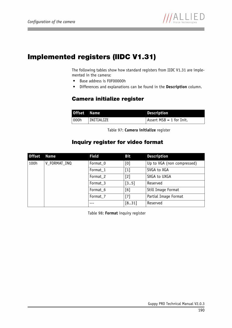
Configuration of the camera
Guppy PRO Technical Manual V2.0.3
190
Implemented registers (IIDC V1.31)
The following tables show how standard registers from IIDC V1.31 are imple-mented in the camera:• Base address is F0F00000h• Differences and explanations can be found in the Description column.
Camera initialize register
Inquiry register for video format
Offset Name Description
000h INITIALIZE Assert MSB = 1 for Init.
Table 97: Camera initialize register
Offset Name Field Bit Description
100h V_FORMAT_INQ Format_0 [0] Up to VGA (non compressed)
Format_1 [1] SVGA to XGA
Format_2 [2] SXGA to UXGA
Format_3 [3..5] Reserved
Format_6 [6] Still Image Format
Format_7 [7] Partial Image Format
--- [8..31] Reserved
Table 98: Format inquiry register
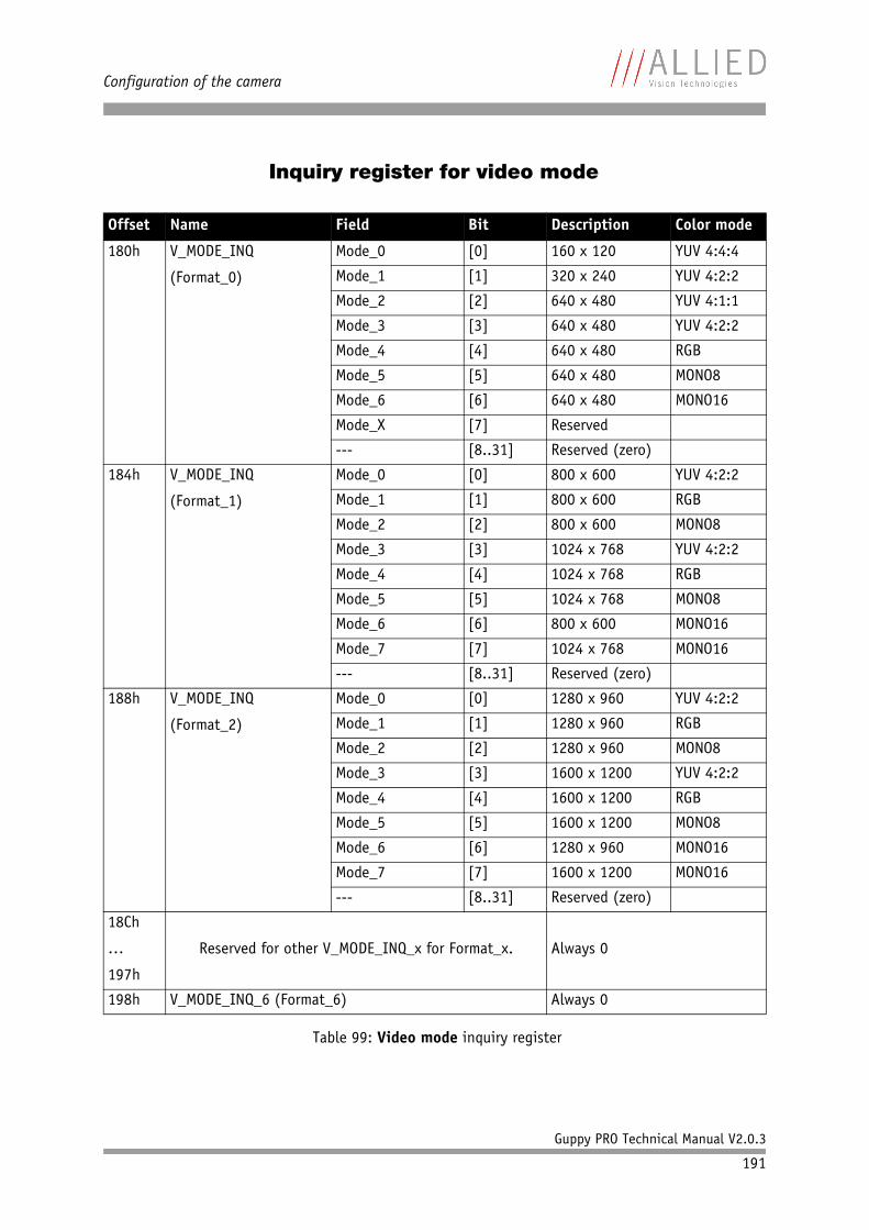
Configuration of the camera
Guppy PRO Technical Manual V2.0.3
191
Inquiry register for video mode
Offset Name Field Bit Description Color mode
180h V_MODE_INQ
(Format_0)
Mode_0 [0] 160 x 120 YUV 4:4:4
Mode_1 [1] 320 x 240 YUV 4:2:2
Mode_2 [2] 640 x 480 YUV 4:1:1
Mode_3 [3] 640 x 480 YUV 4:2:2
Mode_4 [4] 640 x 480 RGB
Mode_5 [5] 640 x 480 MONO8
Mode_6 [6] 640 x 480 MONO16
Mode_X [7] Reserved
--- [8..31] Reserved (zero)
184h V_MODE_INQ
(Format_1)
Mode_0 [0] 800 x 600 YUV 4:2:2
Mode_1 [1] 800 x 600 RGB
Mode_2 [2] 800 x 600 MONO8
Mode_3 [3] 1024 x 768 YUV 4:2:2
Mode_4 [4] 1024 x 768 RGB
Mode_5 [5] 1024 x 768 MONO8
Mode_6 [6] 800 x 600 MONO16
Mode_7 [7] 1024 x 768 MONO16
--- [8..31] Reserved (zero)
188h V_MODE_INQ
(Format_2)
Mode_0 [0] 1280 x 960 YUV 4:2:2
Mode_1 [1] 1280 x 960 RGB
Mode_2 [2] 1280 x 960 MONO8
Mode_3 [3] 1600 x 1200 YUV 4:2:2
Mode_4 [4] 1600 x 1200 RGB
Mode_5 [5] 1600 x 1200 MONO8
Mode_6 [6] 1280 x 960 MONO16
Mode_7 [7] 1600 x 1200 MONO16
--- [8..31] Reserved (zero)
18Ch
…
197h
Reserved for other V_MODE_INQ_x for Format_x. Always 0
198h V_MODE_INQ_6 (Format_6) Always 0
Table 99: Video mode inquiry register
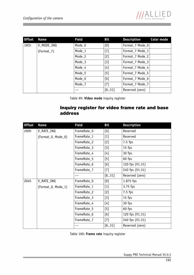
Configuration of the camera
Guppy PRO Technical Manual V2.0.3
192
Inquiry register for video frame rate and base address
19Ch V_MODE_INQ
(Format_7)
Mode_0 [0] Format_7 Mode_0
Mode_1 [1] Format_7 Mode_1
Mode_2 [2] Format_7 Mode_2
Mode_3 [3] Format_7 Mode_3
Mode_4 [4] Format_7 Mode_4
Mode_5 [5] Format_7 Mode_5
Mode_6 [6] Format_7 Mode_6
Mode_7 [7] Format_7 Mode_7
--- [8..31] Reserved (zero)
Offset Name Field Bit Description
200h V_RATE_INQ
(Format_0, Mode_0)
FrameRate_0 [0] Reserved
FrameRate_1 [1] Reserved
FrameRate_2 [2] 7.5 fps
FrameRate_3 [3] 15 fps
FrameRate_4 [4] 30 fps
FrameRate_5 [5] 60 fps
FrameRate_6 [6] 120 fps (V1.31)
FrameRate_7 [7] 240 fps (V1.31)
--- [8..31] Reserved (zero)
204h V_RATE_INQ
(Format_0, Mode_1)
FrameRate_0 [0] 1.875 fps
FrameRate_1 [1] 3.75 fps
FrameRate_2 [2] 7.5 fps
FrameRate_3 [3] 15 fps
FrameRate_4 [4] 30 fps
FrameRate_5 [5] 60 fps
FrameRate_6 [6] 120 fps (V1.31)
FrameRate_7 [7] 240 fps (V1.31)
--- [8..31] Reserved (zero)
Table 100: Frame rate inquiry register
Offset Name Field Bit Description Color mode
Table 99: Video mode inquiry register

Configuration of the camera
Guppy PRO Technical Manual V2.0.3
193
208h V_RATE_INQ
(Format_0, Mode_2)
FrameRate_0 [0] 1.875 fps
FrameRate_1 [1] 3.75 fps
FrameRate_2 [2] 7.5 fps
FrameRate_3 [3] 15 fps
FrameRate_4 [4] 30 fps
FrameRate_5 [5] 60 fps
FrameRate_6 [6] 120 fps (V1.31)
FrameRate_7 [7] 240 fps (V1.31)
--- [8..31] Reserved (zero)
20Ch V_RATE_INQ
(Format_0, Mode_3)
FrameRate_0 [0] 1.875 fps
FrameRate_1 [1] 3.75 fps
FrameRate_2 [2] 7.5 fps
FrameRate_3 [3] 15 fps
FrameRate_4 [4] 30 fps
FrameRate_5 [5] 60 fps
FrameRate_6 [6] 120 fps (V1.31)
FrameRate_7 [7] 240 fps (V1.31)
--- [8..31] Reserved (zero)
210h V_RATE_INQ
(Format_0, Mode_4)
FrameRate_0 [0] 1.875 fps
FrameRate_1 [1] 3.75 fps
FrameRate_2 [2] 7.5 fps
FrameRate_3 [3] 15 fps
FrameRate_4 [4] 30 fps
FrameRate_5 [5] 60 fps
FrameRate_6 [6] 120 fps (V1.31)
FrameRate_7 [7] 240 fps (V1.31)
--- [8..31] Reserved (zero)
Offset Name Field Bit Description
Table 100: Frame rate inquiry register
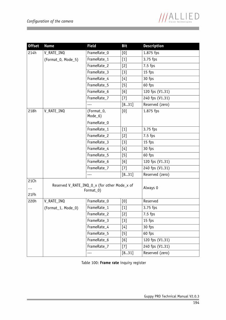
Configuration of the camera
Guppy PRO Technical Manual V2.0.3
194
214h V_RATE_INQ
(Format_0, Mode_5)
FrameRate_0 [0] 1.875 fps
FrameRate_1 [1] 3.75 fps
FrameRate_2 [2] 7.5 fps
FrameRate_3 [3] 15 fps
FrameRate_4 [4] 30 fps
FrameRate_5 [5] 60 fps
FrameRate_6 [6] 120 fps (V1.31)
FrameRate_7 [7] 240 fps (V1.31)
--- [8..31] Reserved (zero)
218h V_RATE_INQ (Format_0, Mode_6)
FrameRate_0
[0] 1.875 fps
FrameRate_1 [1] 3.75 fps
FrameRate_2 [2] 7.5 fps
FrameRate_3 [3] 15 fps
FrameRate_4 [4] 30 fps
FrameRate_5 [5] 60 fps
FrameRate_6 [6] 120 fps (V1.31)
FrameRate_7 [7] 240 fps (V1.31)
--- [8..31] Reserved (zero)
21Ch
…
21Fh
Reserved V_RATE_INQ_0_x (for other Mode_x of Format_0)
Always 0
220h V_RATE_INQ
(Format_1, Mode_0)
FrameRate_0 [0] Reserved
FrameRate_1 [1] 3.75 fps
FrameRate_2 [2] 7.5 fps
FrameRate_3 [3] 15 fps
FrameRate_4 [4] 30 fps
FrameRate_5 [5] 60 fps
FrameRate_6 [6] 120 fps (V1.31)
FrameRate_7 [7] 240 fps (V1.31)
--- [8..31] Reserved (zero)
Offset Name Field Bit Description
Table 100: Frame rate inquiry register

Configuration of the camera
Guppy PRO Technical Manual V2.0.3
195
224h V_RATE_INQ
(Format_1, Mode_1)
FrameRate_0 [0] Reserved
FrameRate_1 [1] Reserved
FrameRate_2 [2] 7.5 fps
FrameRate_3 [3] 15 fps
FrameRate_4 [4] 30 fps
FrameRate_5 [5] 60 fps
FrameRate_6 [6] 120 fps (V1.31)
FrameRate_7 [7] 240 fps (V1.31)
--- [8..31] Reserved (zero)
228h V_RATE_INQ
(Format_1, Mode_2)
FrameRate_0 [0] Reserved
FrameRate_1 [1] Reserved
FrameRate_2 [2] 7.5 fps
FrameRate_3 [3] 15 fps
FrameRate_4 [4] 30 fps
FrameRate_5 [5] 60 fps
FrameRate_6 [6] 120 fps (V1.31)
FrameRate_7 [7] 240 fps (V1.31)
--- [8..31] Reserved (zero)
22Ch V_RATE_INQ (Format_1, Mode_3)
FrameRate_0 [0] 1.875 fps
FrameRate_1 [1] 3.75 fps
FrameRate_2 [2] 7.5 fps
FrameRate_3 [3] 15 fps
FrameRate_4 [4] 30 fps
FrameRate_5 [5] 60 fps
FrameRate_6 [6] 120 fps (V1.31)
FrameRate_7 [7] 240 fps (V1.31)
--- [8..31] Reserved (zero)
Offset Name Field Bit Description
Table 100: Frame rate inquiry register
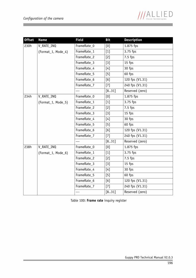
Configuration of the camera
Guppy PRO Technical Manual V2.0.3
196
230h V_RATE_INQ
(Format_1, Mode_4)
FrameRate_0 [0] 1.875 fps
FrameRate_1 [1] 3.75 fps
FrameRate_2 [2] 7.5 fps
FrameRate_3 [3] 15 fps
FrameRate_4 [4] 30 fps
FrameRate_5 [5] 60 fps
FrameRate_6 [6] 120 fps (V1.31)
FrameRate_7 [7] 240 fps (V1.31)
--- [8..31] Reserved (zero)
234h V_RATE_INQ
(Format_1, Mode_5)
FrameRate_0 [0] 1.875 fps
FrameRate_1 [1] 3.75 fps
FrameRate_2 [2] 7.5 fps
FrameRate_3 [3] 15 fps
FrameRate_4 [4] 30 fps
FrameRate_5 [5] 60 fps
FrameRate_6 [6] 120 fps (V1.31)
FrameRate_7 [7] 240 fps (V1.31)
--- [8..31] Reserved (zero)
238h V_RATE_INQ
(Format_1, Mode_6)
FrameRate_0 [0] 1.875 fps
FrameRate_1 [1] 3.75 fps
FrameRate_2 [2] 7.5 fps
FrameRate_3 [3] 15 fps
FrameRate_4 [4] 30 fps
FrameRate_5 [5] 60 fps
FrameRate_6 [6] 120 fps (V1.31)
FrameRate_7 [7] 240 fps (V1.31)
--- [8..31] Reserved (zero)
Offset Name Field Bit Description
Table 100: Frame rate inquiry register

Configuration of the camera
Guppy PRO Technical Manual V2.0.3
197
23Ch V_RATE_INQ
(Format_1, Mode_7)
FrameRate_0 [0] 1.875 fps
FrameRate_1 [1] 3.75 fps
FrameRate_2 [2] 7.5 fps
FrameRate_3 [3] 15 fps
FrameRate_4 [4] 30 fps
FrameRate_5 [5] 60 fps
FrameRate_6 [6] 120 fps (V1.31)
FrameRate_7 [7] Reserved
--- [8..31] Reserved (zero)
240h V_RATE_INQ
(Format_2, Mode_0)
FrameRate_0 [0] 1.875 fps
FrameRate_1 [1] 3.75 fps
FrameRate_2 [2] 7.5 fps
FrameRate_3 [3] 15 fps
FrameRate_4 [4] 30 fps
FrameRate_5 [5] 60 fps
FrameRate_6 [6] Reserved
FrameRate_7 [7] Reserved
--- [8..31] Reserved (zero)
244h V_RATE_INQ
(Format_2, Mode_1)
FrameRate_0 [0] 1.875 fps
FrameRate_1 [1] 3.75 fps
FrameRate_2 [2] 7.5 fps
FrameRate_3 [3] 15 fps
FrameRate_4 [4] 30 fps
FrameRate_5 [5] 60 fps
FrameRate_6 [6] Reserved
FrameRate_7 [7] Reserved
--- [8..31] Reserved (zero)
Offset Name Field Bit Description
Table 100: Frame rate inquiry register
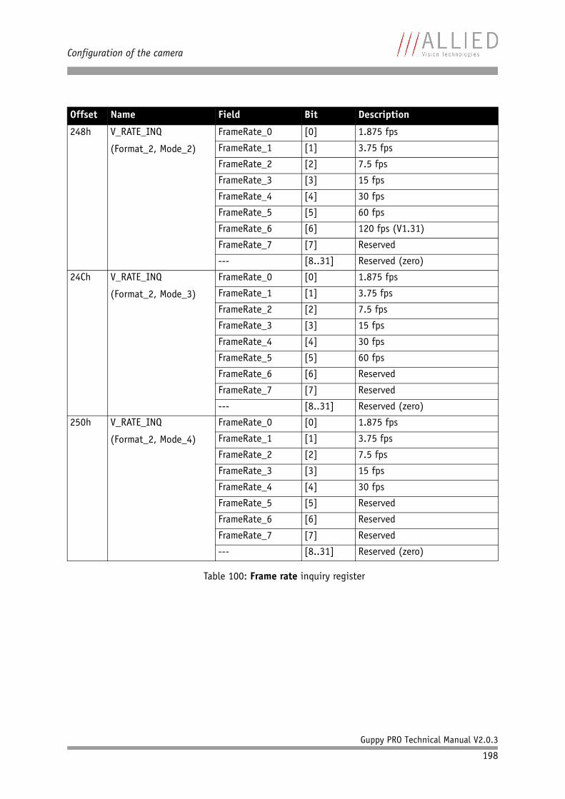
Configuration of the camera
Guppy PRO Technical Manual V2.0.3
198
248h V_RATE_INQ
(Format_2, Mode_2)
FrameRate_0 [0] 1.875 fps
FrameRate_1 [1] 3.75 fps
FrameRate_2 [2] 7.5 fps
FrameRate_3 [3] 15 fps
FrameRate_4 [4] 30 fps
FrameRate_5 [5] 60 fps
FrameRate_6 [6] 120 fps (V1.31)
FrameRate_7 [7] Reserved
--- [8..31] Reserved (zero)
24Ch V_RATE_INQ
(Format_2, Mode_3)
FrameRate_0 [0] 1.875 fps
FrameRate_1 [1] 3.75 fps
FrameRate_2 [2] 7.5 fps
FrameRate_3 [3] 15 fps
FrameRate_4 [4] 30 fps
FrameRate_5 [5] 60 fps
FrameRate_6 [6] Reserved
FrameRate_7 [7] Reserved
--- [8..31] Reserved (zero)
250h V_RATE_INQ
(Format_2, Mode_4)
FrameRate_0 [0] 1.875 fps
FrameRate_1 [1] 3.75 fps
FrameRate_2 [2] 7.5 fps
FrameRate_3 [3] 15 fps
FrameRate_4 [4] 30 fps
FrameRate_5 [5] Reserved
FrameRate_6 [6] Reserved
FrameRate_7 [7] Reserved
--- [8..31] Reserved (zero)
Offset Name Field Bit Description
Table 100: Frame rate inquiry register
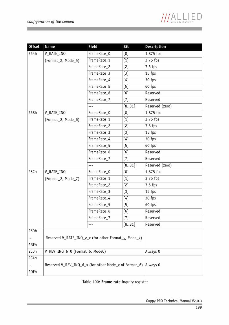
Configuration of the camera
Guppy PRO Technical Manual V2.0.3
199
254h V_RATE_INQ
(Format_2, Mode_5)
FrameRate_0 [0] 1.875 fps
FrameRate_1 [1] 3.75 fps
FrameRate_2 [2] 7.5 fps
FrameRate_3 [3] 15 fps
FrameRate_4 [4] 30 fps
FrameRate_5 [5] 60 fps
FrameRate_6 [6] Reserved
FrameRate_7 [7] Reserved
--- [8..31] Reserved (zero)
258h V_RATE_INQ
(Format_2, Mode_6)
FrameRate_0 [0] 1.875 fps
FrameRate_1 [1] 3.75 fps
FrameRate_2 [2] 7.5 fps
FrameRate_3 [3] 15 fps
FrameRate_4 [4] 30 fps
FrameRate_5 [5] 60 fps
FrameRate_6 [6] Reserved
FrameRate_7 [7] Reserved
--- [8..31] Reserved (zero)
25Ch V_RATE_INQ
(Format_2, Mode_7)
FrameRate_0 [0] 1.875 fps
FrameRate_1 [1] 3.75 fps
FrameRate_2 [2] 7.5 fps
FrameRate_3 [3] 15 fps
FrameRate_4 [4] 30 fps
FrameRate_5 [5] 60 fps
FrameRate_6 [6] Reserved
FrameRate_7 [7] Reserved
--- [8..31] Reserved
260h
…
2BFh
Reserved V_RATE_INQ_y_x (for other Format_y, Mode_x)
2C0h V_REV_INQ_6_0 (Format_6, Mode0) Always 0
2C4h
..
2DFh
Reserved V_REV_INQ_6_x (for other Mode_x of Format_6) Always 0
Offset Name Field Bit Description
Table 100: Frame rate inquiry register
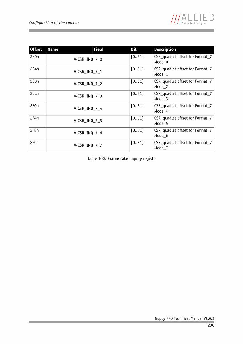
Configuration of the camera
Guppy PRO Technical Manual V2.0.3
200
2E0hV-CSR_INQ_7_0
[0..31] CSR_quadlet offset for Format_7 Mode_0
2E4hV-CSR_INQ_7_1
[0..31] CSR_quadlet offset for Format_7 Mode_1
2E8hV-CSR_INQ_7_2
[0..31] CSR_quadlet offset for Format_7 Mode_2
2EChV-CSR_INQ_7_3
[0..31] CSR_quadlet offset for Format_7 Mode_3
2F0hV-CSR_INQ_7_4
[0..31] CSR_quadlet offset for Format_7 Mode_4
2F4hV-CSR_INQ_7_5
[0..31] CSR_quadlet offset for Format_7 Mode_5
2F8hV-CSR_INQ_7_6
[0..31] CSR_quadlet offset for Format_7 Mode_6
2FChV-CSR_INQ_7_7
[0..31] CSR_quadlet offset for Format_7 Mode_7
Offset Name Field Bit Description
Table 100: Frame rate inquiry register
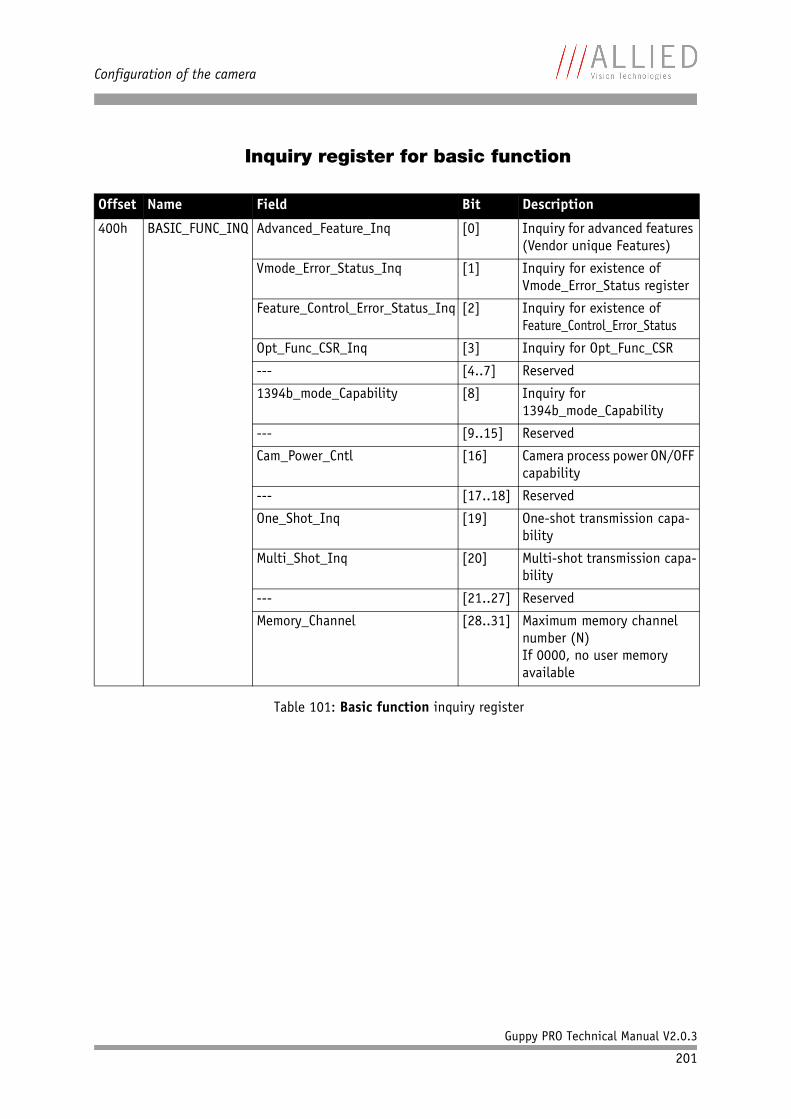
Configuration of the camera
Guppy PRO Technical Manual V2.0.3
201
Inquiry register for basic function
Offset Name Field Bit Description
400h BASIC_FUNC_INQ Advanced_Feature_Inq [0] Inquiry for advanced features (Vendor unique Features)
Vmode_Error_Status_Inq [1] Inquiry for existence of Vmode_Error_Status register
Feature_Control_Error_Status_Inq [2] Inquiry for existence of Feature_Control_Error_Status
Opt_Func_CSR_Inq [3] Inquiry for Opt_Func_CSR
--- [4..7] Reserved
1394b_mode_Capability [8] Inquiry for 1394b_mode_Capability
--- [9..15] Reserved
Cam_Power_Cntl [16] Camera process power ON/OFF capability
--- [17..18] Reserved
One_Shot_Inq [19] One-shot transmission capa-bility
Multi_Shot_Inq [20] Multi-shot transmission capa-bility
--- [21..27] Reserved
Memory_Channel [28..31] Maximum memory channel number (N)If 0000, no user memory available
Table 101: Basic function inquiry register
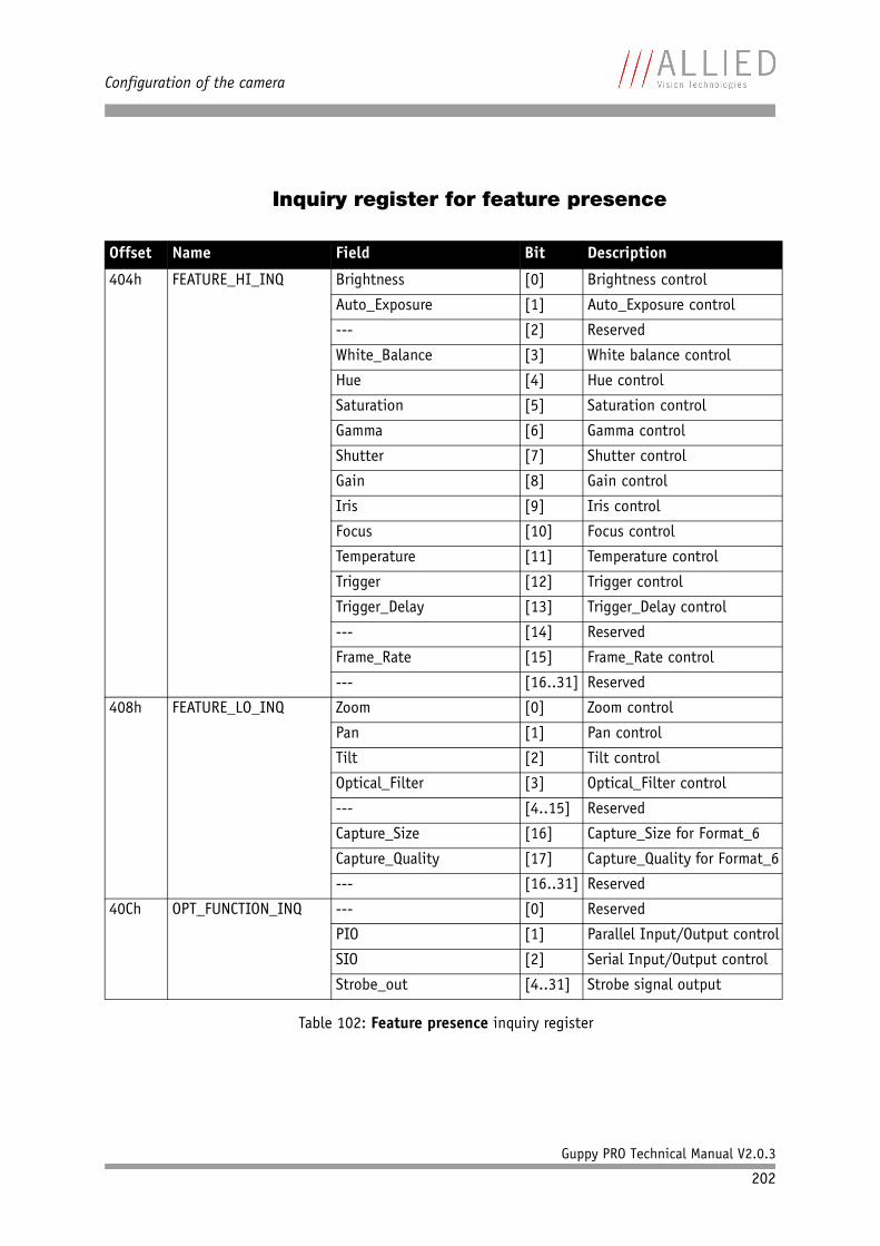
Configuration of the camera
Guppy PRO Technical Manual V2.0.3
202
Inquiry register for feature presence
Offset Name Field Bit Description
404h FEATURE_HI_INQ Brightness [0] Brightness control
Auto_Exposure [1] Auto_Exposure control
--- [2] Reserved
White_Balance [3] White balance control
Hue [4] Hue control
Saturation [5] Saturation control
Gamma [6] Gamma control
Shutter [7] Shutter control
Gain [8] Gain control
Iris [9] Iris control
Focus [10] Focus control
Temperature [11] Temperature control
Trigger [12] Trigger control
Trigger_Delay [13] Trigger_Delay control
--- [14] Reserved
Frame_Rate [15] Frame_Rate control
--- [16..31] Reserved
408h FEATURE_LO_INQ Zoom [0] Zoom control
Pan [1] Pan control
Tilt [2] Tilt control
Optical_Filter [3] Optical_Filter control
--- [4..15] Reserved
Capture_Size [16] Capture_Size for Format_6
Capture_Quality [17] Capture_Quality for Format_6
--- [16..31] Reserved
40Ch OPT_FUNCTION_INQ --- [0] Reserved
PIO [1] Parallel Input/Output control
SIO [2] Serial Input/Output control
Strobe_out [4..31] Strobe signal output
Table 102: Feature presence inquiry register
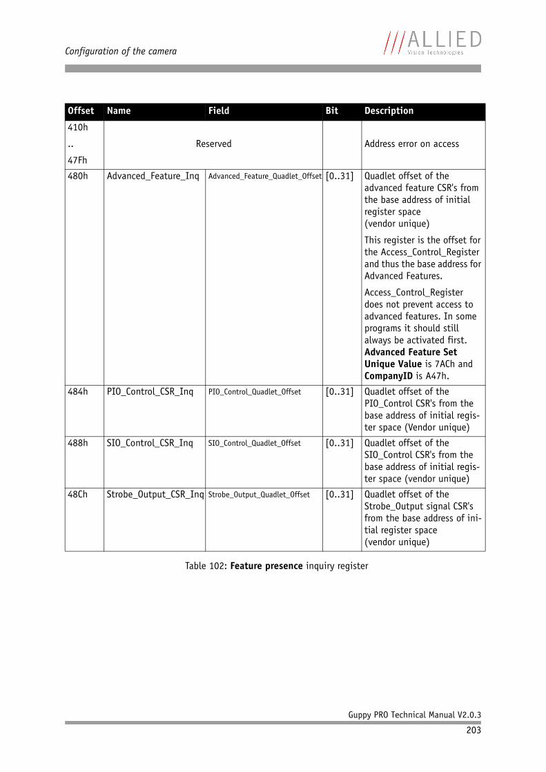
Configuration of the camera
Guppy PRO Technical Manual V2.0.3
203
410h
..
47Fh
Reserved Address error on access
480h Advanced_Feature_Inq Advanced_Feature_Quadlet_Offset [0..31] Quadlet offset of the advanced feature CSR's from the base address of initial register space(vendor unique)
This register is the offset for the Access_Control_Register and thus the base address for Advanced Features.
Access_Control_Register does not prevent access to advanced features. In some programs it should still always be activated first.Advanced Feature Set Unique Value is 7ACh and CompanyID is A47h.
484h PIO_Control_CSR_Inq PIO_Control_Quadlet_Offset [0..31] Quadlet offset of the PIO_Control CSR's from the base address of initial regis-ter space (Vendor unique)
488h SIO_Control_CSR_Inq SIO_Control_Quadlet_Offset [0..31] Quadlet offset of the SIO_Control CSR's from the base address of initial regis-ter space (vendor unique)
48Ch Strobe_Output_CSR_Inq Strobe_Output_Quadlet_Offset [0..31] Quadlet offset of the Strobe_Output signal CSR's from the base address of ini-tial register space(vendor unique)
Offset Name Field Bit Description
Table 102: Feature presence inquiry register
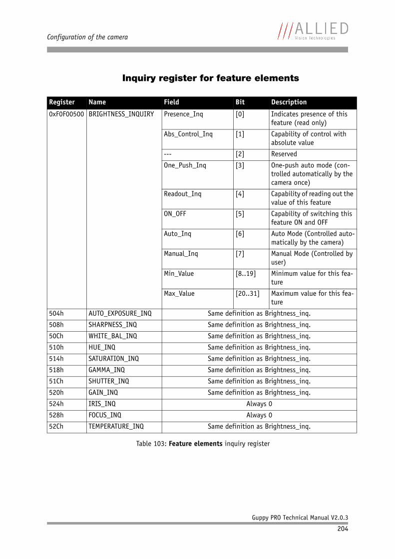
Configuration of the camera
Guppy PRO Technical Manual V2.0.3
204
Inquiry register for feature elements
Register Name Field Bit Description
0xF0F00500 BRIGHTNESS_INQUIRY Presence_Inq [0] Indicates presence of this feature (read only)
Abs_Control_Inq [1] Capability of control with absolute value
--- [2] Reserved
One_Push_Inq [3] One-push auto mode (con-trolled automatically by the camera once)
Readout_Inq [4] Capability of reading out the value of this feature
ON_OFF [5] Capability of switching this feature ON and OFF
Auto_Inq [6] Auto Mode (Controlled auto-matically by the camera)
Manual_Inq [7] Manual Mode (Controlled by user)
Min_Value [8..19] Minimum value for this fea-ture
Max_Value [20..31] Maximum value for this fea-ture
504h AUTO_EXPOSURE_INQ Same definition as Brightness_inq.
508h SHARPNESS_INQ Same definition as Brightness_inq.
50Ch WHITE_BAL_INQ Same definition as Brightness_inq.
510h HUE_INQ Same definition as Brightness_inq.
514h SATURATION_INQ Same definition as Brightness_inq.
518h GAMMA_INQ Same definition as Brightness_inq.
51Ch SHUTTER_INQ Same definition as Brightness_inq.
520h GAIN_INQ Same definition as Brightness_inq.
524h IRIS_INQ Always 0
528h FOCUS_INQ Always 0
52Ch TEMPERATURE_INQ Same definition as Brightness_inq.
Table 103: Feature elements inquiry register
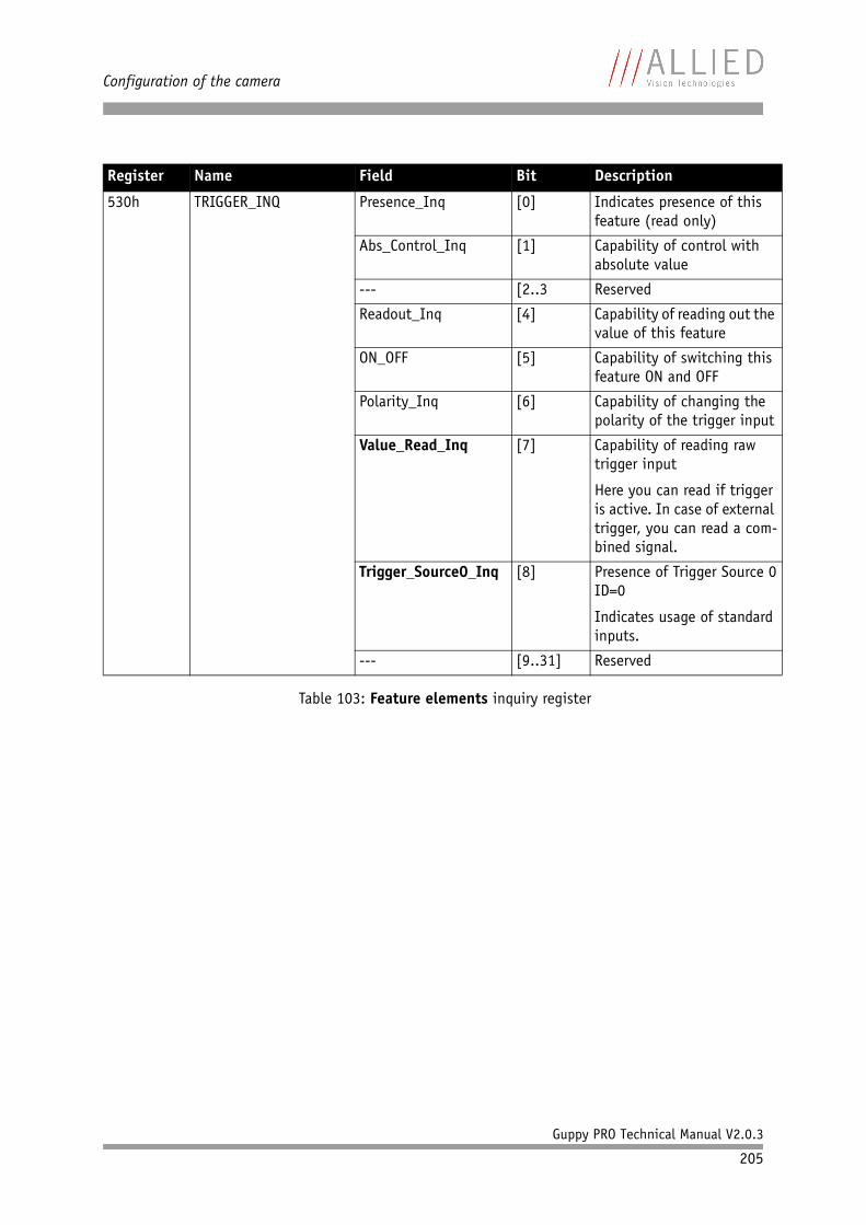
Configuration of the camera
Guppy PRO Technical Manual V2.0.3
205
530h TRIGGER_INQ Presence_Inq [0] Indicates presence of this feature (read only)
Abs_Control_Inq [1] Capability of control with absolute value
--- [2..3 Reserved
Readout_Inq [4] Capability of reading out the value of this feature
ON_OFF [5] Capability of switching this feature ON and OFF
Polarity_Inq [6] Capability of changing the polarity of the trigger input
Value_Read_Inq [7] Capability of reading raw trigger input
Here you can read if trigger is active. In case of external trigger, you can read a com-bined signal.
Trigger_Source0_Inq [8] Presence of Trigger Source 0ID=0
Indicates usage of standard inputs.
--- [9..31] Reserved
Register Name Field Bit Description
Table 103: Feature elements inquiry register
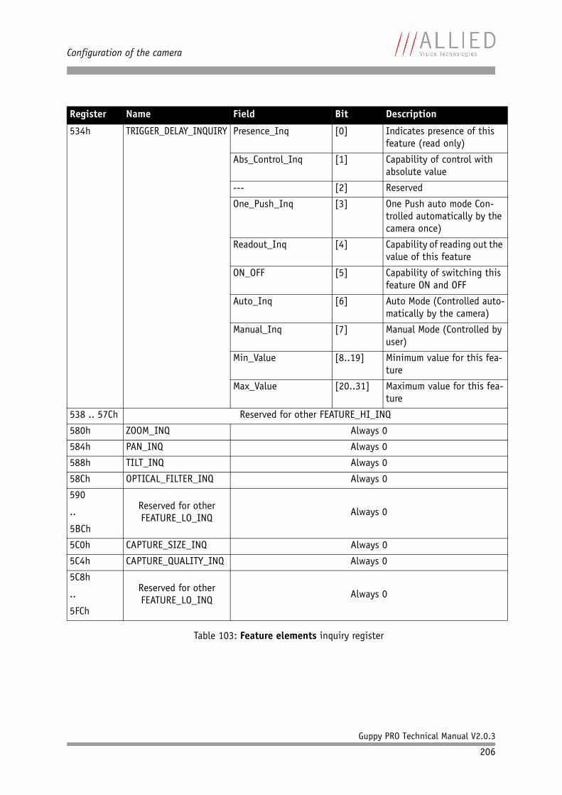
Configuration of the camera
Guppy PRO Technical Manual V2.0.3
206
534h TRIGGER_DELAY_INQUIRY Presence_Inq [0] Indicates presence of this feature (read only)
Abs_Control_Inq [1] Capability of control with absolute value
--- [2] Reserved
One_Push_Inq [3] One Push auto mode Con-trolled automatically by the camera once)
Readout_Inq [4] Capability of reading out the value of this feature
ON_OFF [5] Capability of switching this feature ON and OFF
Auto_Inq [6] Auto Mode (Controlled auto-matically by the camera)
Manual_Inq [7] Manual Mode (Controlled by user)
Min_Value [8..19] Minimum value for this fea-ture
Max_Value [20..31] Maximum value for this fea-ture
538 .. 57Ch Reserved for other FEATURE_HI_INQ
580h ZOOM_INQ Always 0
584h PAN_INQ Always 0
588h TILT_INQ Always 0
58Ch OPTICAL_FILTER_INQ Always 0
590
..
5BCh
Reserved for other FEATURE_LO_INQ
Always 0
5C0h CAPTURE_SIZE_INQ Always 0
5C4h CAPTURE_QUALITY_INQ Always 0
5C8h
..
5FCh
Reserved for other FEATURE_LO_INQ
Always 0
Register Name Field Bit Description
Table 103: Feature elements inquiry register
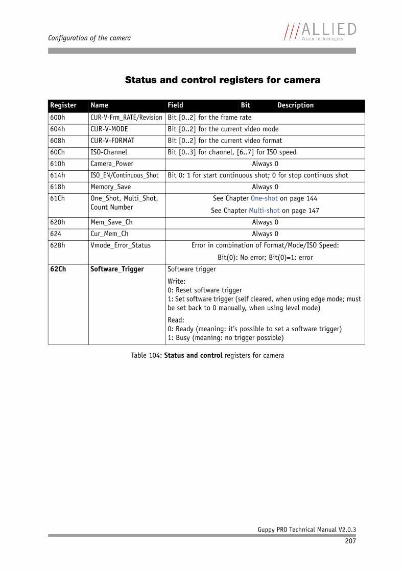
Configuration of the camera
Guppy PRO Technical Manual V2.0.3
207
Status and control registers for camera
Register Name Field Bit Description
600h CUR-V-Frm_RATE/Revision Bit [0..2] for the frame rate
604h CUR-V-MODE Bit [0..2] for the current video mode
608h CUR-V-FORMAT Bit [0..2] for the current video format
60Ch ISO-Channel Bit [0..3] for channel, [6..7] for ISO speed
610h Camera_Power Always 0
614h ISO_EN/Continuous_Shot Bit 0: 1 for start continuous shot; 0 for stop continuos shot
618h Memory_Save Always 0
61Ch One_Shot, Multi_Shot, Count Number
See Chapter One-shot on page 144
See Chapter Multi-shot on page 147
620h Mem_Save_Ch Always 0
624 Cur_Mem_Ch Always 0
628h Vmode_Error_Status Error in combination of Format/Mode/ISO Speed:
Bit(0): No error; Bit(0)=1: error
62Ch Software_Trigger Software trigger
Write:0: Reset software trigger1: Set software trigger (self cleared, when using edge mode; must be set back to 0 manually, when using level mode)
Read:0: Ready (meaning: it’s possible to set a software trigger)1: Busy (meaning: no trigger possible)
Table 104: Status and control registers for camera
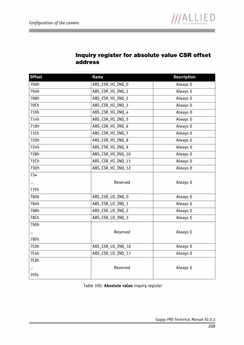
Configuration of the camera
Guppy PRO Technical Manual V2.0.3
208
Inquiry register for absolute value CSR offset address
Offset Name Description
700h ABS_CSR_HI_INQ_0 Always 0
704h ABS_CSR_HI_INQ_1 Always 0
708h ABS_CSR_HI_INQ_2 Always 0
70Ch ABS_CSR_HI_INQ_3 Always 0
710h ABS_CSR_HI_INQ_4 Always 0
714h ABS_CSR_HI_INQ_5 Always 0
718h ABS_CSR_HI_INQ_6 Always 0
71Ch ABS_CSR_HI_INQ_7 Always 0
720h ABS_CSR_HI_INQ_8 Always 0
724h ABS_CSR_HI_INQ_9 Always 0
728h ABS_CSR_HI_INQ_10 Always 0
72Ch ABS_CSR_HI_INQ_11 Always 0
730h ABS_CSR_HI_INQ_12 Always 0
734
..
77Fh
Reserved Always 0
780h ABS_CSR_LO_INQ_0 Always 0
784h ABS_CSR_LO_INQ_1 Always 0
788h ABS_CSR_LO_INQ_2 Always 0
78Ch ABS_CSR_LO_INQ_3 Always 0
790h
..
7BFh
Reserved Always 0
7C0h ABS_CSR_LO_INQ_16 Always 0
7C4h ABS_CSR_LO_INQ_17 Always 0
7C8h
..
7FFh
Reserved Always 0
Table 105: Absolute value inquiry register
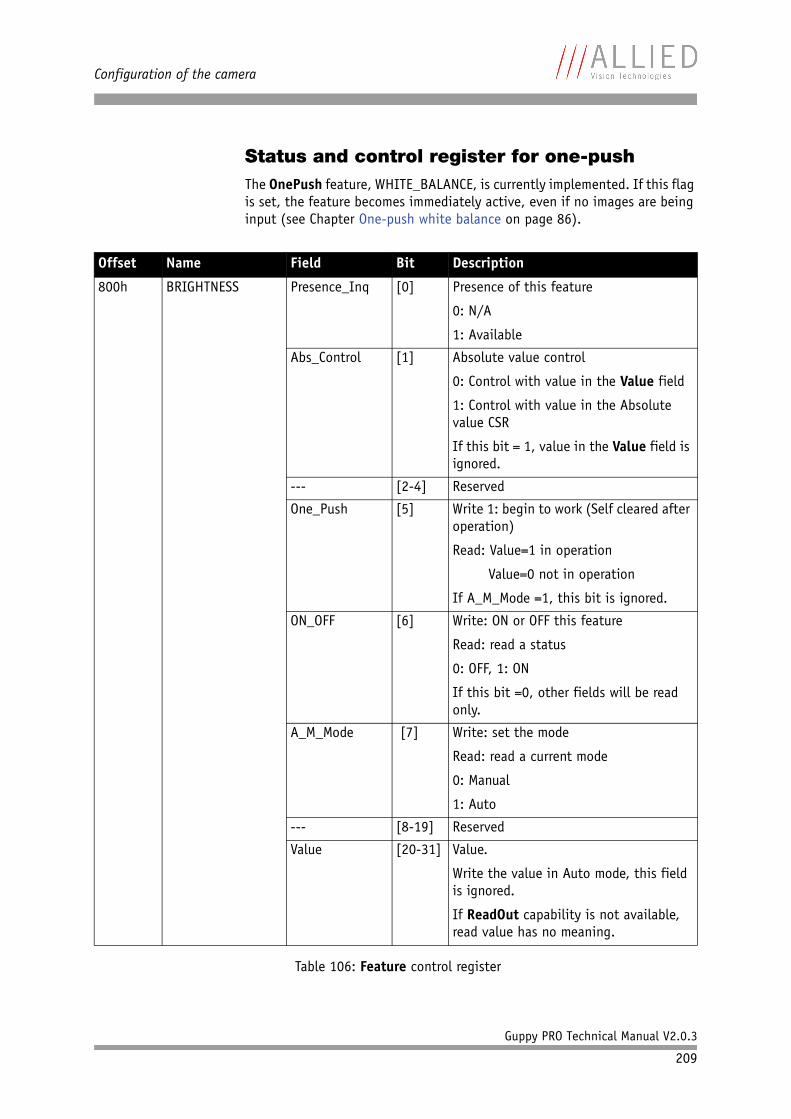
Configuration of the camera
Guppy PRO Technical Manual V2.0.3
209
Status and control register for one-pushThe OnePush feature, WHITE_BALANCE, is currently implemented. If this flag is set, the feature becomes immediately active, even if no images are being input (see Chapter One-push white balance on page 86).
Offset Name Field Bit Description
800h BRIGHTNESS Presence_Inq [0] Presence of this feature
0: N/A
1: Available
Abs_Control [1] Absolute value control
0: Control with value in the Value field
1: Control with value in the Absolute value CSR
If this bit = 1, value in the Value field is ignored.
--- [2-4] Reserved
One_Push [5] Write 1: begin to work (Self cleared after operation)
Read: Value=1 in operation
Value=0 not in operation
If A_M_Mode =1, this bit is ignored.
ON_OFF [6] Write: ON or OFF this feature
Read: read a status
0: OFF, 1: ON
If this bit =0, other fields will be read only.
A_M_Mode [7] Write: set the mode
Read: read a current mode
0: Manual
1: Auto
--- [8-19] Reserved
Value [20-31] Value.
Write the value in Auto mode, this field is ignored.
If ReadOut capability is not available, read value has no meaning.
Table 106: Feature control register

Configuration of the camera
Guppy PRO Technical Manual V2.0.3
210
804h AUTO-EXPOSURE See above
Note: Target grey level parameter in SmartView corresponds to Auto_exposure register 0xF0F00804 (IIDC).
Offset Name Field Bit Description
Table 106: Feature control register
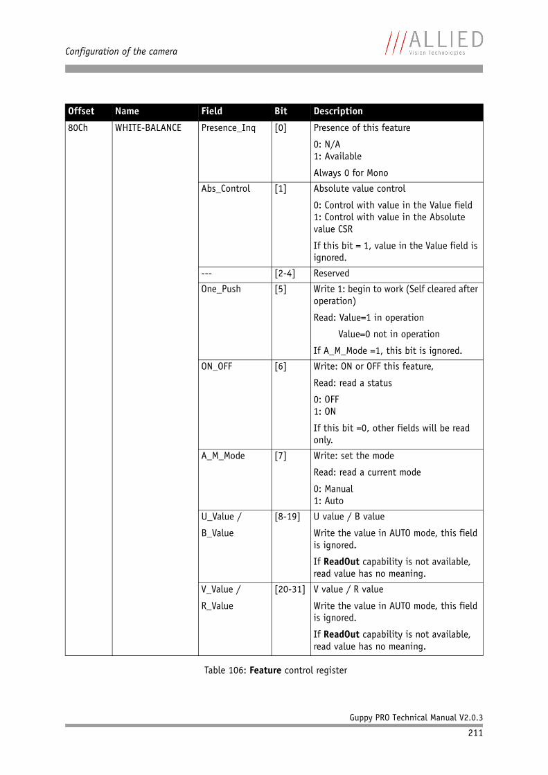
Configuration of the camera
Guppy PRO Technical Manual V2.0.3
211
80Ch WHITE-BALANCE Presence_Inq [0] Presence of this feature
0: N/A1: Available
Always 0 for Mono
Abs_Control [1] Absolute value control
0: Control with value in the Value field1: Control with value in the Absolute value CSR
If this bit = 1, value in the Value field is ignored.
--- [2-4] Reserved
One_Push [5] Write 1: begin to work (Self cleared after operation)
Read: Value=1 in operation
Value=0 not in operation
If A_M_Mode =1, this bit is ignored.
ON_OFF [6] Write: ON or OFF this feature,
Read: read a status
0: OFF1: ON
If this bit =0, other fields will be read only.
A_M_Mode [7] Write: set the mode
Read: read a current mode
0: Manual1: Auto
U_Value /
B_Value
[8-19] U value / B value
Write the value in AUTO mode, this field is ignored.
If ReadOut capability is not available, read value has no meaning.
V_Value /
R_Value
[20-31] V value / R value
Write the value in AUTO mode, this field is ignored.
If ReadOut capability is not available, read value has no meaning.
Offset Name Field Bit Description
Table 106: Feature control register
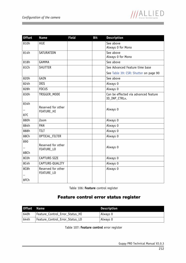
Configuration of the camera
Guppy PRO Technical Manual V2.0.3
212
Feature control error status register
810h HUE See aboveAlways 0 for Mono
814h SATURATION See aboveAlways 0 for Mono
818h GAMMA See above
81Ch SHUTTER See Advanced Feature time base
See Table 39: CSR: Shutter on page 90
820h GAIN See above
824h IRIS Always 0
828h FOCUS Always 0
830h TRIGGER_MODE Can be effected via advanced feature IO_INP_CTRLx.
834h
..
87C
Reserved for other FEATURE_HI
Always 0
880h Zoom Always 0
884h PAN Always 0
888h TILT Always 0
88Ch OPTICAL_FILTER Always 0
890
..
8BCh
Reserved for other FEATURE_LO
Always 0
8C0h CAPTURE-SIZE Always 0
8C4h CAPTURE-QUALITY Always 0
8C8h
..
8FCh
Reserved for other FEATURE_LO
Always 0
Offset Name Description
640h Feature_Control_Error_Status_HI Always 0
644h Feature_Control_Error_Status_LO Always 0
Table 107: Feature control error register
Offset Name Field Bit Description
Table 106: Feature control register
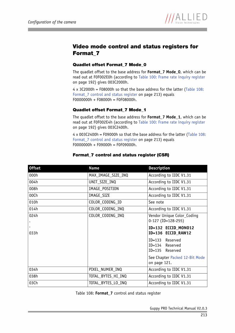
Configuration of the camera
Guppy PRO Technical Manual V2.0.3
213
Video mode control and status registers for Format_7
Quadlet offset Format_7 Mode_0
The quadlet offset to the base address for Format_7 Mode_0, which can be read out at F0F002E0h (according to Table 100: Frame rate inquiry register on page 192) gives 003C2000h.
4 x 3C2000h = F08000h so that the base address for the latter (Table 108: Format_7 control and status register on page 213) equalsF0000000h + F08000h = F0F08000h.
Quadlet offset Format_7 Mode_1
The quadlet offset to the base address for Format_7 Mode_1, which can be read out at F0F002E4h (according to Table 100: Frame rate inquiry register on page 192) gives 003C2400h.
4 x 003C2400h = F09000h so that the base address for the latter (Table 108: Format_7 control and status register on page 213) equalsF0000000h + F09000h = F0F09000h.
Format_7 control and status register (CSR)
Offset Name Description
000h MAX_IMAGE_SIZE_INQ According to IIDC V1.31
004h UNIT_SIZE_INQ According to IIDC V1.31
008h IMAGE_POSITION According to IIDC V1.31
00Ch IMAGE_SIZE According to IIDC V1.31
010h COLOR_CODING_ID See note
014h COLOR_CODING_INQ According to IIDC V1.31
024h..
033h
COLOR_CODING_INQ Vendor Unique Color_Coding0-127 (ID=128-255)
ID=132 ECCID_MONO12ID=136 ECCID_RAW12
ID=133 ReservedID=134 ReservedID=135 Reserved
See Chapter Packed 12-Bit Mode on page 121.
034h PIXEL_NUMER_INQ According to IIDC V1.31
038h TOTAL_BYTES_HI_INQ According to IIDC V1.31
03Ch TOTAL_BYTES_LO_INQ According to IIDC V1.31
Table 108: Format_7 control and status register
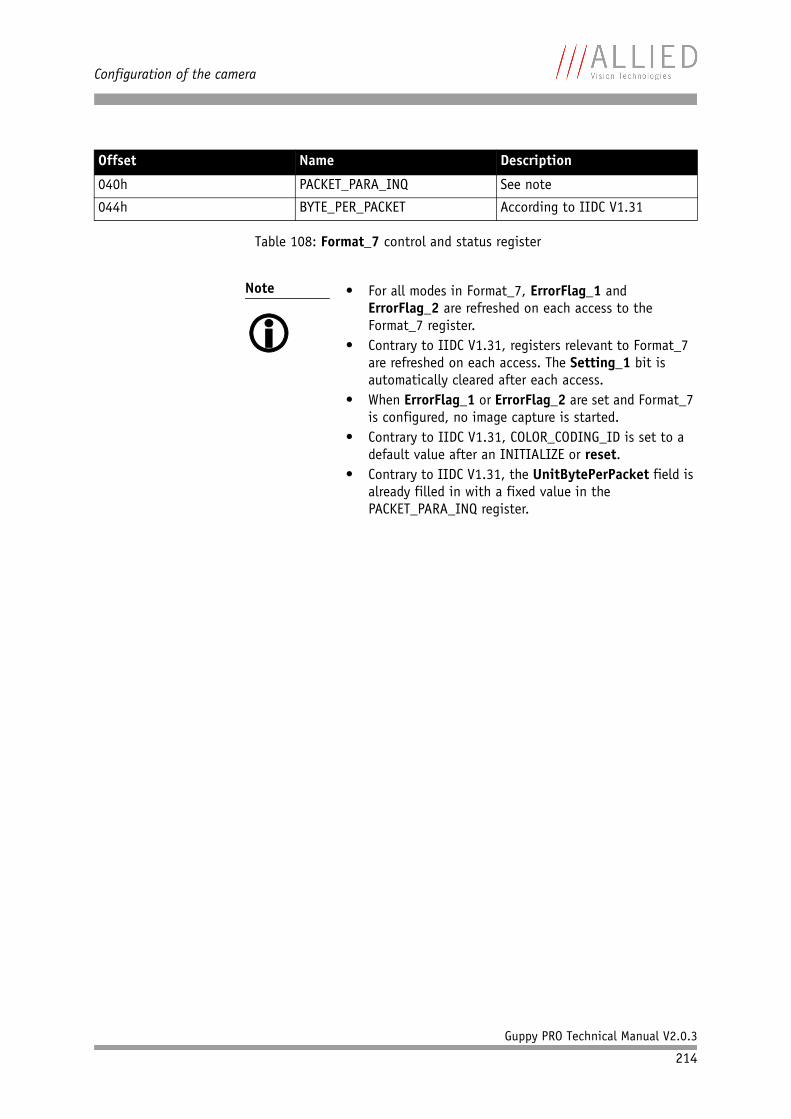
Configuration of the camera
Guppy PRO Technical Manual V2.0.3
214
040h PACKET_PARA_INQ See note
044h BYTE_PER_PACKET According to IIDC V1.31
Note
• For all modes in Format_7, ErrorFlag_1 and
ErrorFlag_2 are refreshed on each access to the Format_7 register.
• Contrary to IIDC V1.31, registers relevant to Format_7 are refreshed on each access. The Setting_1 bit is automatically cleared after each access.
• When ErrorFlag_1 or ErrorFlag_2 are set and Format_7 is configured, no image capture is started.
• Contrary to IIDC V1.31, COLOR_CODING_ID is set to a default value after an INITIALIZE or reset.
• Contrary to IIDC V1.31, the UnitBytePerPacket field is already filled in with a fixed value in the PACKET_PARA_INQ register.
Offset Name Description
Table 108: Format_7 control and status register
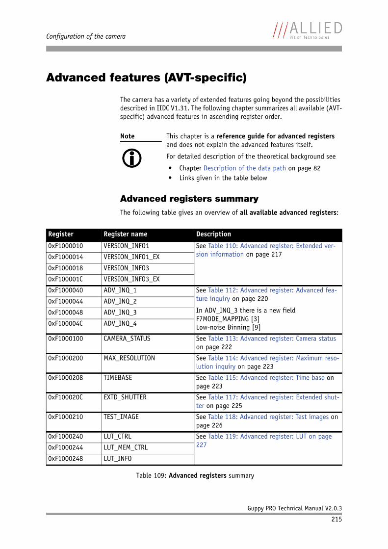
Configuration of the camera
Guppy PRO Technical Manual V2.0.3
215
Advanced features (AVT-specific)
The camera has a variety of extended features going beyond the possibilities described in IIDC V1.31. The following chapter summarizes all available (AVT-specific) advanced features in ascending register order.
Advanced registers summaryThe following table gives an overview of all available advanced registers:
Note
This chapter is a reference guide for advanced registers and does not explain the advanced features itself.
For detailed description of the theoretical background see
• Chapter Description of the data path on page 82• Links given in the table below
Register Register name Description
0xF1000010 VERSION_INFO1 See Table 110: Advanced register: Extended ver-sion information on page 2170xF1000014 VERSION_INFO1_EX
0xF1000018 VERSION_INFO3
0xF100001C VERSION_INFO3_EX
0xF1000040 ADV_INQ_1 See Table 112: Advanced register: Advanced fea-ture inquiry on page 220
In ADV_INQ_3 there is a new field F7MODE_MAPPING [3]Low-noise Binning [9]
0xF1000044 ADV_INQ_2
0xF1000048 ADV_INQ_3
0xF100004C ADV_INQ_4
0xF1000100 CAMERA_STATUS See Table 113: Advanced register: Camera status on page 222
0xF1000200 MAX_RESOLUTION See Table 114: Advanced register: Maximum reso-lution inquiry on page 223
0xF1000208 TIMEBASE See Table 115: Advanced register: Time base on page 223
0xF100020C EXTD_SHUTTER See Table 117: Advanced register: Extended shut-ter on page 225
0xF1000210 TEST_IMAGE See Table 118: Advanced register: Test images on page 226
0xF1000240 LUT_CTRL See Table 119: Advanced register: LUT on page 2270xF1000244 LUT_MEM_CTRL
0xF1000248 LUT_INFO
Table 109: Advanced registers summary
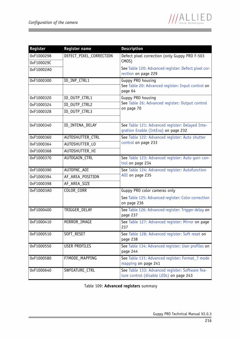
Configuration of the camera
Guppy PRO Technical Manual V2.0.3
216
0xF1000298 DEFECT_PIXEL_CORRECTION Defect pixel correction (only Guppy PRO F-503 CMOS)
See Table 120: Advanced register: Defect pixel cor-rection on page 229
0xF100029C
0xF10002A0
0xF1000300 IO_INP_CTRL1 Guppy PRO housingSee Table 20: Advanced register: Input control on page 64
0xF1000320 IO_OUTP_CTRL1 Guppy PRO housingSee Table 26: Advanced register: Output control on page 70
0xF1000324 IO_OUTP_CTRL2
0xF1000328 IO_OUTP_CTRL3
0xF1000340 IO_INTENA_DELAY See Table 121: Advanced register: Delayed Inte-gration Enable (IntEna) on page 232
0xF1000360 AUTOSHUTTER_CTRL See Table 122: Advanced register: Auto shutter control on page 2330xF1000364 AUTOSHUTTER_LO
0xF1000368 AUTOSHUTTER_HI
0xF1000370 AUTOGAIN_CTRL See Table 123: Advanced register: Auto gain con-trol on page 234
0xF1000390 AUTOFNC_AOI See Table 124: Advanced register: Autofunction AOI on page 2350xF1000394 AF_AREA_POSITION
0xF1000398 AF_AREA_SIZE
0xF10003A0 COLOR_CORR Guppy PRO color cameras only
See Table 125: Advanced register: Color correction on page 236
0xF1000400 TRIGGER_DELAY See Table 126: Advanced register: Trigger delay on page 237
0xF1000410 MIRROR_IMAGE See Table 127: Advanced register: Mirror on page 237
0xF1000510 SOFT_RESET See Table 128: Advanced register: Soft reset on page 238
0xF1000550 USER PROFILES See Table 134: Advanced register: User profiles on page 244
0xF1000580 F7MODE_MAPPING See Table 131: Advanced register: Format_7 mode mapping on page 241
0xF1000640 SWFEATURE_CTRL See Table 133: Advanced register: Software fea-ture control (disable LEDs) on page 243
Register Register name Description
Table 109: Advanced registers summary
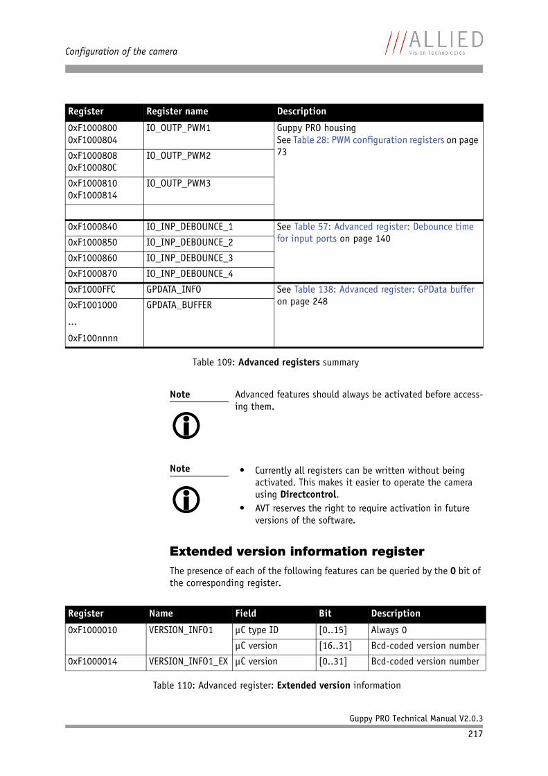
Configuration of the camera
Guppy PRO Technical Manual V2.0.3
217
Extended version information registerThe presence of each of the following features can be queried by the 0 bit of the corresponding register.
0xF10008000xF1000804
IO_OUTP_PWM1 Guppy PRO housingSee Table 28: PWM configuration registers on page 730xF1000808
0xF100080CIO_OUTP_PWM2
0xF10008100xF1000814
IO_OUTP_PWM3
0xF1000840 IO_INP_DEBOUNCE_1 See Table 57: Advanced register: Debounce time for input ports on page 1400xF1000850 IO_INP_DEBOUNCE_2
0xF1000860 IO_INP_DEBOUNCE_3
0xF1000870 IO_INP_DEBOUNCE_4
0xF1000FFC GPDATA_INFO See Table 138: Advanced register: GPData buffer on page 2480xF1001000
...
0xF100nnnn
GPDATA_BUFFER
Note
Advanced features should always be activated before access-ing them.
Note
• Currently all registers can be written without being
activated. This makes it easier to operate the camera using Directcontrol.
• AVT reserves the right to require activation in future versions of the software.
Register Name Field Bit Description
0xF1000010 VERSION_INFO1 µC type ID [0..15] Always 0
µC version [16..31] Bcd-coded version number
0xF1000014 VERSION_INFO1_EX µC version [0..31] Bcd-coded version number
Table 110: Advanced register: Extended version information
Register Register name Description
Table 109: Advanced registers summary
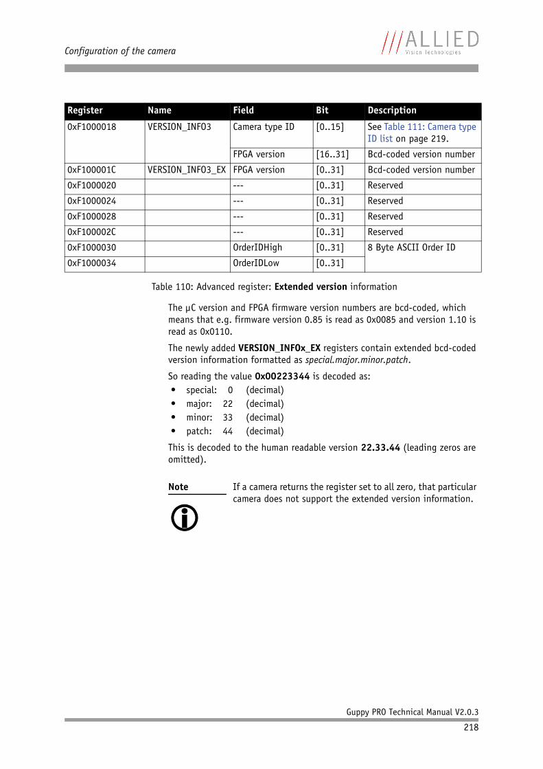
Configuration of the camera
Guppy PRO Technical Manual V2.0.3
218
The µC version and FPGA firmware version numbers are bcd-coded, which means that e.g. firmware version 0.85 is read as 0x0085 and version 1.10 is read as 0x0110.
The newly added VERSION_INFOx_EX registers contain extended bcd-coded version information formatted as special.major.minor.patch.
So reading the value 0x00223344 is decoded as:• special: 0 (decimal)• major: 22 (decimal)• minor: 33 (decimal)• patch: 44 (decimal)
This is decoded to the human readable version 22.33.44 (leading zeros are omitted).
0xF1000018 VERSION_INFO3 Camera type ID [0..15] See Table 111: Camera type ID list on page 219.
FPGA version [16..31] Bcd-coded version number
0xF100001C VERSION_INFO3_EX FPGA version [0..31] Bcd-coded version number
0xF1000020 --- [0..31] Reserved
0xF1000024 --- [0..31] Reserved
0xF1000028 --- [0..31] Reserved
0xF100002C --- [0..31] Reserved
0xF1000030 OrderIDHigh [0..31] 8 Byte ASCII Order ID
0xF1000034 OrderIDLow [0..31]
Note
If a camera returns the register set to all zero, that particular camera does not support the extended version information.
Register Name Field Bit Description
Table 110: Advanced register: Extended version information
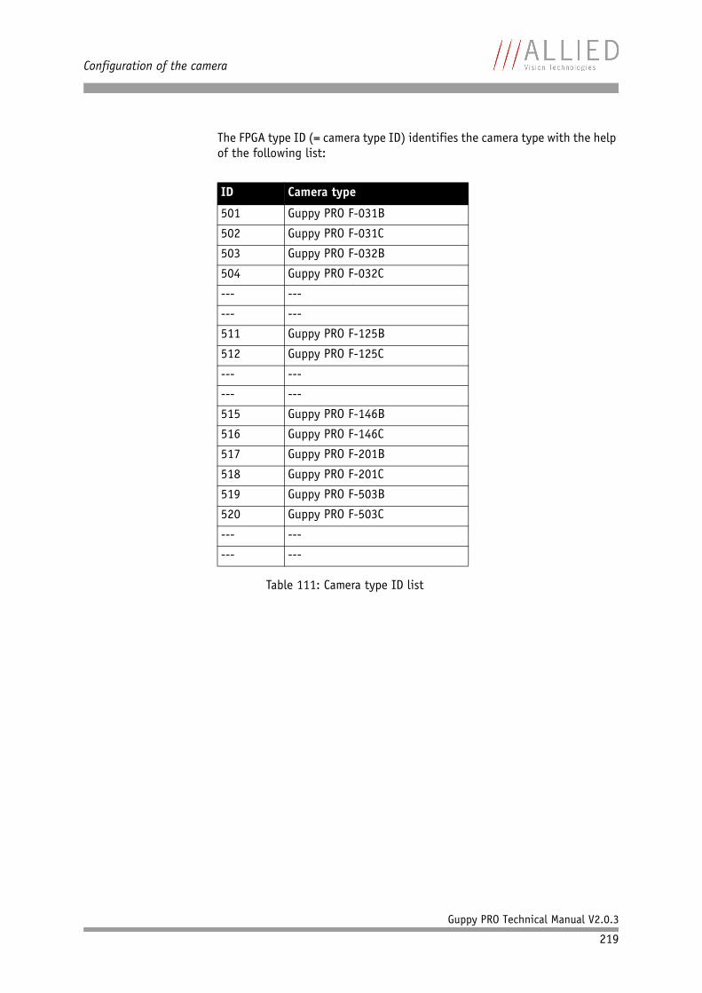
Configuration of the camera
Guppy PRO Technical Manual V2.0.3
219
The FPGA type ID (= camera type ID) identifies the camera type with the help of the following list:
ID Camera type
501 Guppy PRO F-031B
502 Guppy PRO F-031C
503 Guppy PRO F-032B
504 Guppy PRO F-032C
--- ---
--- ---
511 Guppy PRO F-125B
512 Guppy PRO F-125C
--- ---
--- ---
515 Guppy PRO F-146B
516 Guppy PRO F-146C
517 Guppy PRO F-201B
518 Guppy PRO F-201C
519 Guppy PRO F-503B
520 Guppy PRO F-503C
--- ---
--- ---
Table 111: Camera type ID list
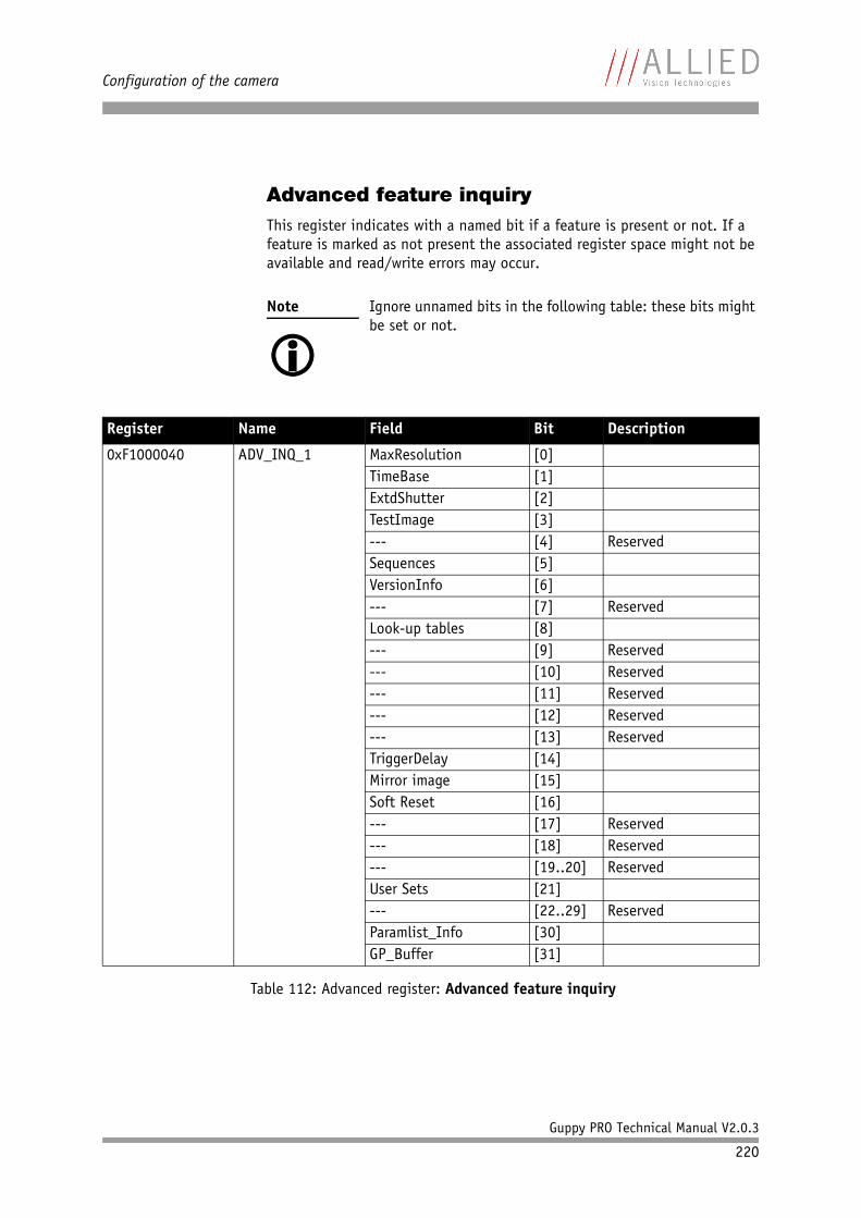
Configuration of the camera
Guppy PRO Technical Manual V2.0.3
220
Advanced feature inquiryThis register indicates with a named bit if a feature is present or not. If a feature is marked as not present the associated register space might not be available and read/write errors may occur.
Note
Ignore unnamed bits in the following table: these bits might be set or not.
Register Name Field Bit Description
0xF1000040 ADV_INQ_1 MaxResolution [0]TimeBase [1]ExtdShutter [2]TestImage [3]--- [4] ReservedSequences [5]VersionInfo [6]--- [7] ReservedLook-up tables [8]--- [9] Reserved--- [10] Reserved--- [11] Reserved--- [12] Reserved--- [13] ReservedTriggerDelay [14]Mirror image [15]Soft Reset [16]--- [17] Reserved--- [18] Reserved--- [19..20] ReservedUser Sets [21]--- [22..29] ReservedParamlist_Info [30]GP_Buffer [31]
Table 112: Advanced register: Advanced feature inquiry
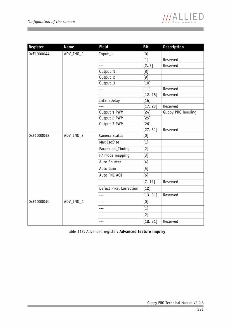
Configuration of the camera
Guppy PRO Technical Manual V2.0.3
221
0xF1000044 ADV_INQ_2 Input_1 [0]--- [1] Reserved--- [2..7] ReservedOutput_1 [8]Output_2 [9]Output_3 [10]--- [11] Reserved--- [12..15] ReservedIntEnaDelay [16]--- [17..23] ReservedOutput 1 PWM [24] Guppy PRO housingOutput 2 PWM [25]Output 3 PWM [26]--- [27..31] Reserved
0xF1000048 ADV_INQ_3 Camera Status [0]
Max IsoSize [1]
Paramupd_Timing [2]
F7 mode mapping [3]
Auto Shutter [4]
Auto Gain [5]
Auto FNC AOI [6]
--- [7..11] Reserved
Defect Pixel Correction [12]
--- [13..31] Reserved
0xF100004C ADV_INQ_4 --- [0]
--- [1]
--- [2]
--- [18..31] Reserved
Register Name Field Bit Description
Table 112: Advanced register: Advanced feature inquiry
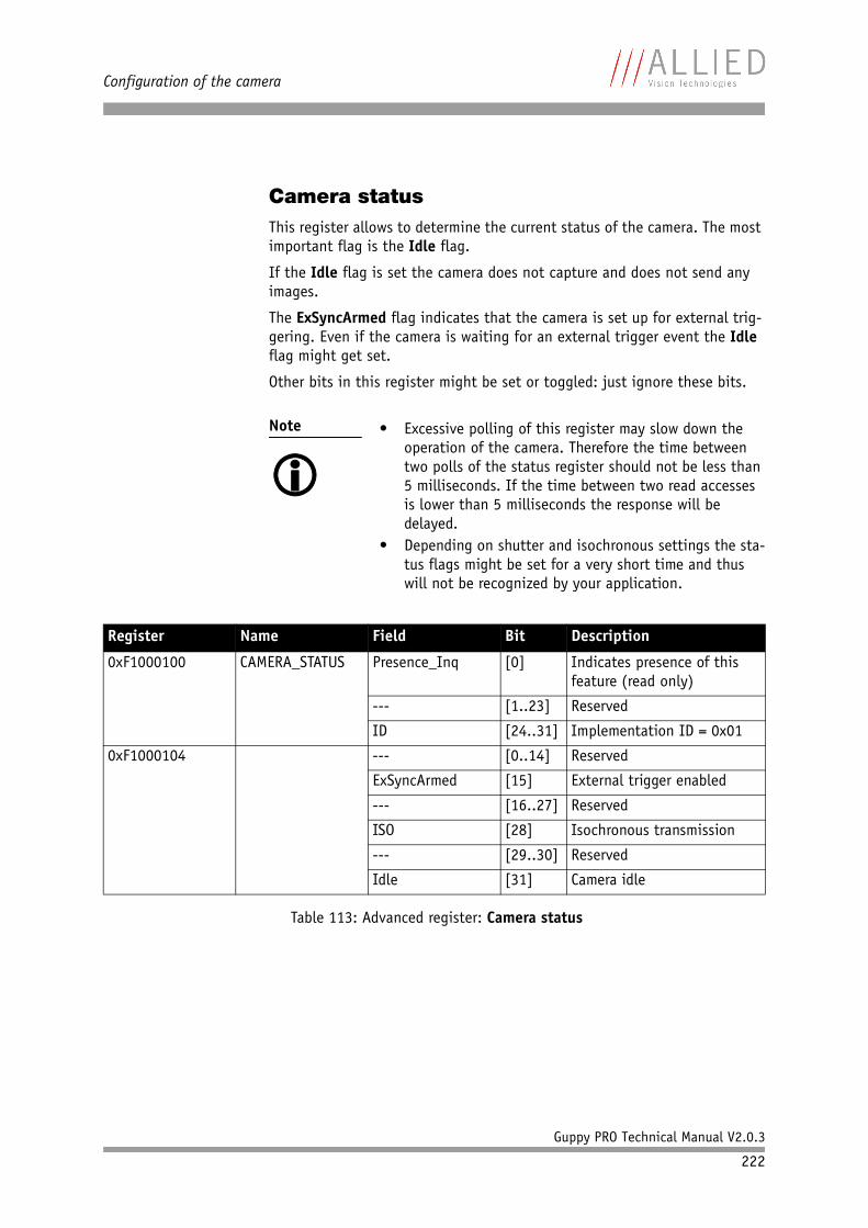
Configuration of the camera
Guppy PRO Technical Manual V2.0.3
222
Camera statusThis register allows to determine the current status of the camera. The most important flag is the Idle flag.
If the Idle flag is set the camera does not capture and does not send any images.
The ExSyncArmed flag indicates that the camera is set up for external trig-gering. Even if the camera is waiting for an external trigger event the Idle flag might get set.
Other bits in this register might be set or toggled: just ignore these bits.
Note
• Excessive polling of this register may slow down the
operation of the camera. Therefore the time between two polls of the status register should not be less than 5 milliseconds. If the time between two read accesses is lower than 5 milliseconds the response will be delayed.
• Depending on shutter and isochronous settings the sta-tus flags might be set for a very short time and thus will not be recognized by your application.
Register Name Field Bit Description
0xF1000100 CAMERA_STATUS Presence_Inq [0] Indicates presence of this feature (read only)
--- [1..23] Reserved
ID [24..31] Implementation ID = 0x01
0xF1000104 --- [0..14] Reserved
ExSyncArmed [15] External trigger enabled
--- [16..27] Reserved
ISO [28] Isochronous transmission
--- [29..30] Reserved
Idle [31] Camera idle
Table 113: Advanced register: Camera status
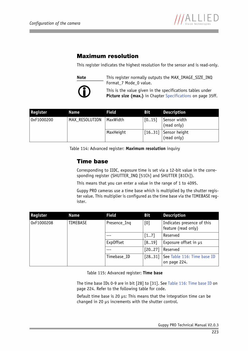
Configuration of the camera
Guppy PRO Technical Manual V2.0.3
223
Maximum resolutionThis register indicates the highest resolution for the sensor and is read-only.
Time baseCorresponding to IIDC, exposure time is set via a 12-bit value in the corre-sponding register (SHUTTER_INQ [51Ch] and SHUTTER [81Ch]).
This means that you can enter a value in the range of 1 to 4095.
Guppy PRO cameras use a time base which is multiplied by the shutter regis-ter value. This multiplier is configured as the time base via the TIMEBASE reg-ister.
The time base IDs 0-9 are in bit [28] to [31]. See Table 116: Time base ID on page 224. Refer to the following table for code.
Default time base is 20 µs: This means that the integration time can be changed in 20 µs increments with the shutter control.
Note
This register normally outputs the MAX_IMAGE_SIZE_INQ Format_7 Mode_0 value.
This is the value given in the specifications tables under Picture size (max.) in Chapter Specifications on page 35ff.
Register Name Field Bit Description
0xF1000200 MAX_RESOLUTION MaxWidth [0..15] Sensor width(read only)
MaxHeight [16..31] Sensor height(read only)
Table 114: Advanced register: Maximum resolution inquiry
Register Name Field Bit Description
0xF1000208 TIMEBASE Presence_Inq [0] Indicates presence of this feature (read only)
--- [1..7] Reserved
ExpOffset [8..19] Exposure offset in µs
--- [20..27] Reserved
Timebase_ID [28..31] See Table 116: Time base ID on page 224.
Table 115: Advanced register: Time base
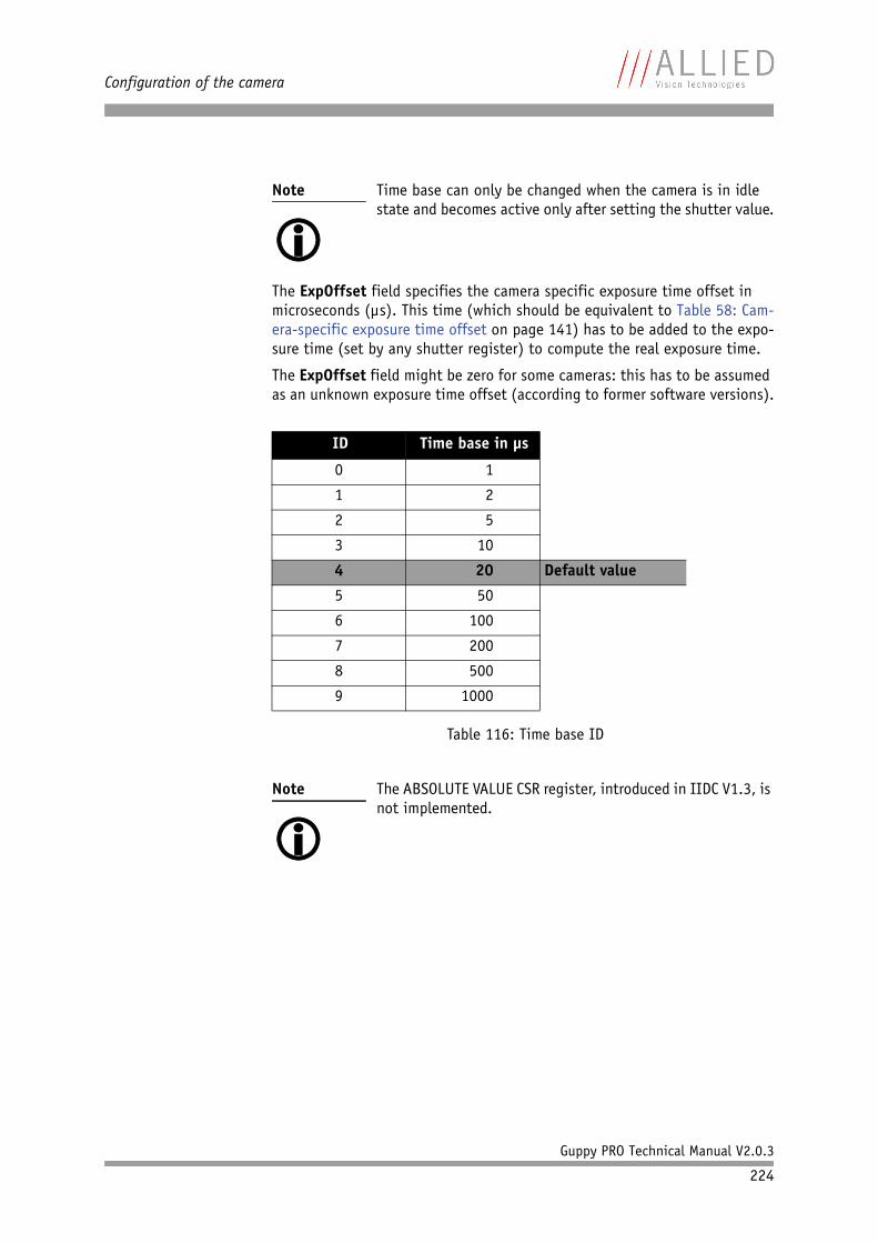
Configuration of the camera
Guppy PRO Technical Manual V2.0.3
224
The ExpOffset field specifies the camera specific exposure time offset in microseconds (µs). This time (which should be equivalent to Table 58: Cam-era-specific exposure time offset on page 141) has to be added to the expo-sure time (set by any shutter register) to compute the real exposure time.
The ExpOffset field might be zero for some cameras: this has to be assumed as an unknown exposure time offset (according to former software versions).
Note
Time base can only be changed when the camera is in idle state and becomes active only after setting the shutter value.
ID Time base in µs
0 1
1 2
2 5
3 10
4 20 Default value
5 50
6 100
7 200
8 500
9 1000
Table 116: Time base ID
Note
The ABSOLUTE VALUE CSR register, introduced in IIDC V1.3, is not implemented.
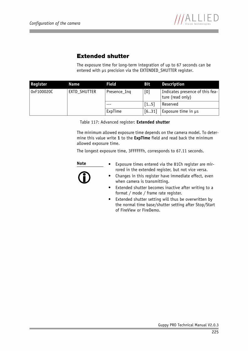
Configuration of the camera
Guppy PRO Technical Manual V2.0.3
225
Extended shutterThe exposure time for long-term integration of up to 67 seconds can be entered with µs precision via the EXTENDED_SHUTTER register.
The minimum allowed exposure time depends on the camera model. To deter-mine this value write 1 to the ExpTime field and read back the minimum allowed exposure time.
The longest exposure time, 3FFFFFFh, corresponds to 67.11 seconds.
Register Name Field Bit Description
0xF100020C EXTD_SHUTTER Presence_Inq [0] Indicates presence of this fea-ture (read only)
--- [1..5] Reserved
ExpTime [6..31] Exposure time in µs
Table 117: Advanced register: Extended shutter
Note
• Exposure times entered via the 81Ch register are mir-
rored in the extended register, but not vice versa.• Changes in this register have immediate effect, even
when camera is transmitting.• Extended shutter becomes inactive after writing to a
format / mode / frame rate register.• Extended shutter setting will thus be overwritten by
the normal time base/shutter setting after Stop/Start of FireView or FireDemo.
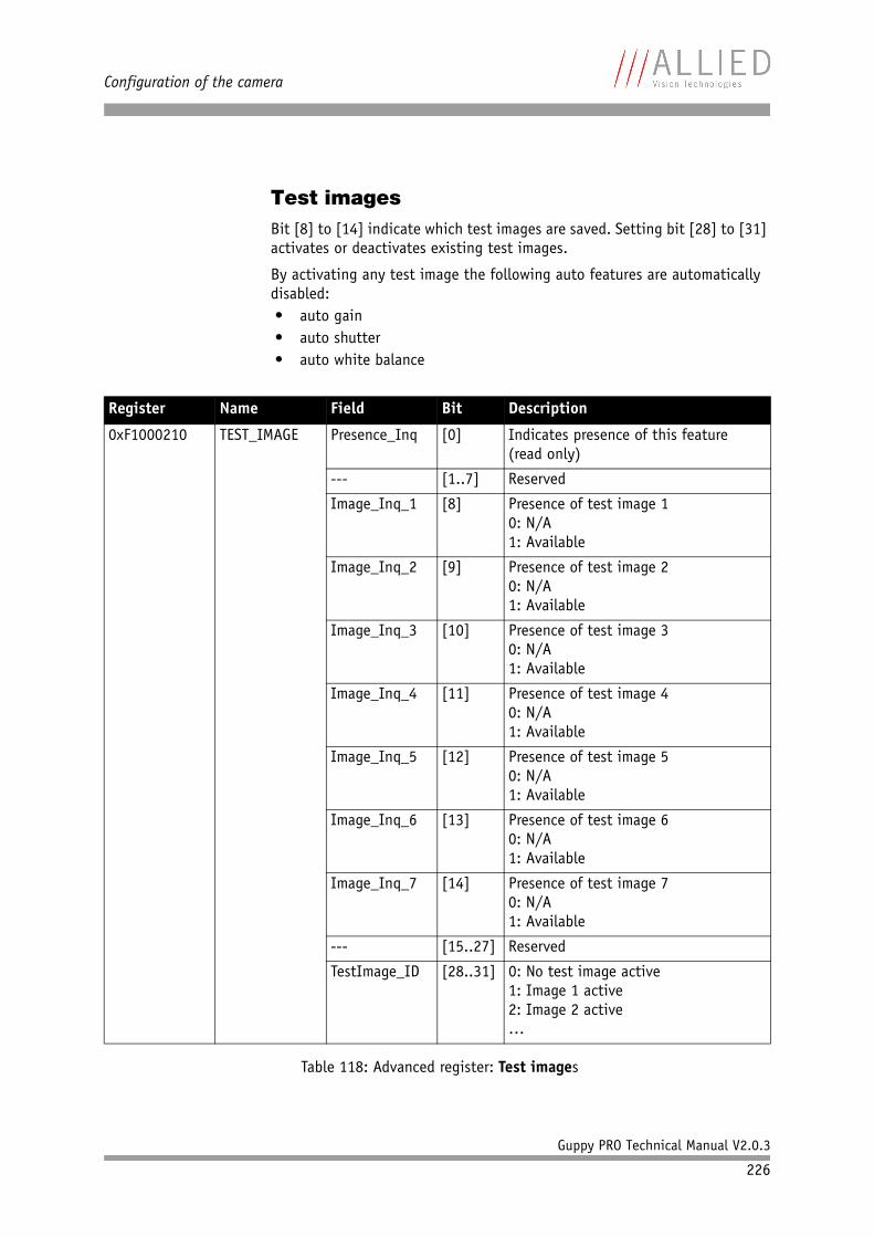
Configuration of the camera
Guppy PRO Technical Manual V2.0.3
226
Test imagesBit [8] to [14] indicate which test images are saved. Setting bit [28] to [31] activates or deactivates existing test images.
By activating any test image the following auto features are automatically disabled:• auto gain• auto shutter• auto white balance
Register Name Field Bit Description
0xF1000210 TEST_IMAGE Presence_Inq [0] Indicates presence of this feature(read only)
--- [1..7] Reserved
Image_Inq_1 [8] Presence of test image 10: N/A1: Available
Image_Inq_2 [9] Presence of test image 20: N/A1: Available
Image_Inq_3 [10] Presence of test image 30: N/A1: Available
Image_Inq_4 [11] Presence of test image 40: N/A1: Available
Image_Inq_5 [12] Presence of test image 50: N/A1: Available
Image_Inq_6 [13] Presence of test image 60: N/A1: Available
Image_Inq_7 [14] Presence of test image 70: N/A1: Available
--- [15..27] Reserved
TestImage_ID [28..31] 0: No test image active1: Image 1 active2: Image 2 active…
Table 118: Advanced register: Test images
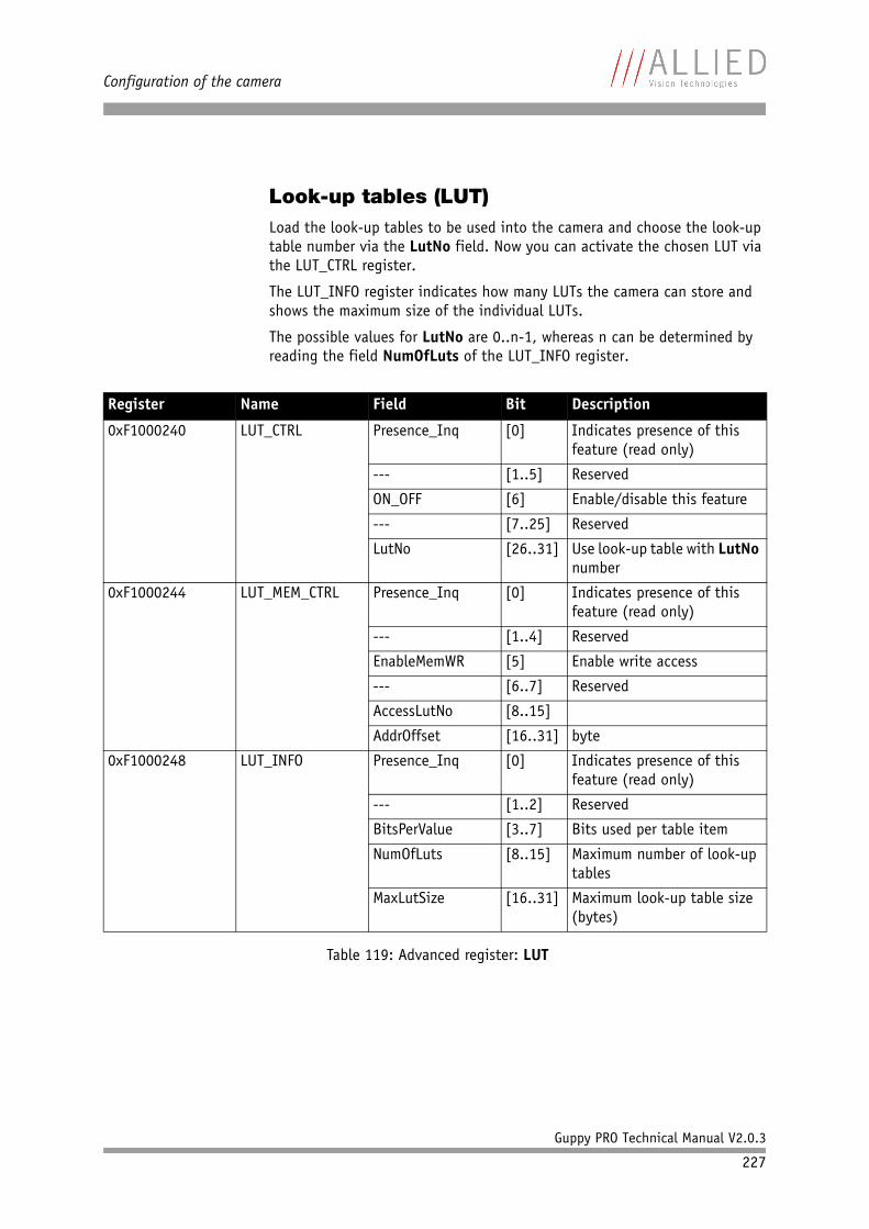
Configuration of the camera
Guppy PRO Technical Manual V2.0.3
227
Look-up tables (LUT)Load the look-up tables to be used into the camera and choose the look-up table number via the LutNo field. Now you can activate the chosen LUT via the LUT_CTRL register.
The LUT_INFO register indicates how many LUTs the camera can store and shows the maximum size of the individual LUTs.
The possible values for LutNo are 0..n-1, whereas n can be determined by reading the field NumOfLuts of the LUT_INFO register.
Register Name Field Bit Description
0xF1000240 LUT_CTRL Presence_Inq [0] Indicates presence of this feature (read only)
--- [1..5] Reserved
ON_OFF [6] Enable/disable this feature
--- [7..25] Reserved
LutNo [26..31] Use look-up table with LutNo number
0xF1000244 LUT_MEM_CTRL Presence_Inq [0] Indicates presence of this feature (read only)
--- [1..4] Reserved
EnableMemWR [5] Enable write access
--- [6..7] Reserved
AccessLutNo [8..15]
AddrOffset [16..31] byte
0xF1000248 LUT_INFO Presence_Inq [0] Indicates presence of this feature (read only)
--- [1..2] Reserved
BitsPerValue [3..7] Bits used per table item
NumOfLuts [8..15] Maximum number of look-up tables
MaxLutSize [16..31] Maximum look-up table size (bytes)
Table 119: Advanced register: LUT
Configuration of the camera
Guppy PRO Technical Manual V2.0.3
228
Loading a look-up table into the camera
Loading a look-up table into the camera is done through the GPDATA_BUFFER. Because the size of the GPDATA_BUFFER is smaller than a complete look-up table the data must be written in multiple steps.
To load a lookup table into the camera:
1. Query the limits and ranges by reading LUT_INFO and GPDATA_INFO.
2. Set EnableMemWR to true (1).
3. Set AccessLutNo to the desired number.
4. Set AddrOffset to 0.
5. Write n lookup table data bytes to GPDATA_BUFFER (n might be lower than the size of the GPDATA_BUFFER; AddrOffset is automatically adjusted inside the camera).
6. Repeat step 5 until all data is written into the camera.
7. Set EnableMemWR to false (0).
Note
The BitsPerValue field indicates how many bits are read from the LUT for any grey-value read from the sensor. To determine the number of bytes occupied for each grey-value round-up the BitsPerValue field to the next byte boundary.
Examples:
• BitsPerValue = 8 1 byte per grey-value• BitsPerValue = 14 2 byte per grey-value
Divide MaxLutSize by the number of bytes per grey-value in order to get the number of LUT entries (grey levels): that is 2n with n=number of bits read from sensor.
Note
Guppy PRO cameras have the gamma feature implemented via a built-in look-up table. Therefore you can not use gamma and your own look-up table at the same time. Nevertheless you may combine a gamma look-up table into your own look-up table.
Note
When using the LUT feature and the gamma feature pay attention to the following:
• gamma ON look-up table is switched ON also• gamma OFF look-up table is switched OFF also• look-up table OFF gamma is switched OFF also• look-up table ON gamma is switched OFF
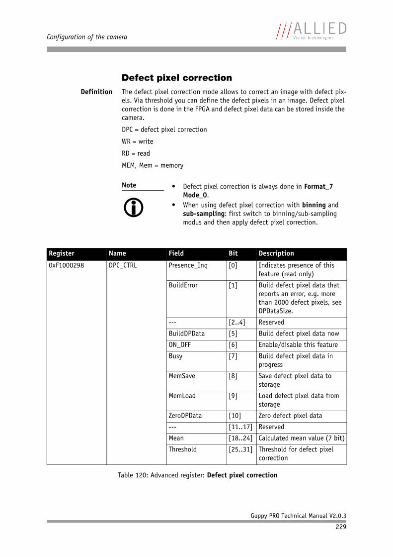
Configuration of the camera
Guppy PRO Technical Manual V2.0.3
229
Defect pixel correctionDefinition The defect pixel correction mode allows to correct an image with defect pix-
els. Via threshold you can define the defect pixels in an image. Defect pixel correction is done in the FPGA and defect pixel data can be stored inside the camera.
DPC = defect pixel correction
WR = write
RD = read
MEM, Mem = memory
Note
• Defect pixel correction is always done in Format_7
Mode_0.• When using defect pixel correction with binning and
sub-sampling: first switch to binning/sub-sampling modus and then apply defect pixel correction.
Register Name Field Bit Description
0xF1000298 DPC_CTRL Presence_Inq [0] Indicates presence of this feature (read only)
BuildError [1] Build defect pixel data that reports an error, e.g. more than 2000 defect pixels, see DPDataSize.
--- [2..4] Reserved
BuildDPData [5] Build defect pixel data now
ON_OFF [6] Enable/disable this feature
Busy [7] Build defect pixel data in progress
MemSave [8] Save defect pixel data to storage
MemLoad [9] Load defect pixel data from storage
ZeroDPData [10] Zero defect pixel data
--- [11..17] Reserved
Mean [18..24] Calculated mean value (7 bit)
Threshold [25..31] Threshold for defect pixel correction
Table 120: Advanced register: Defect pixel correction
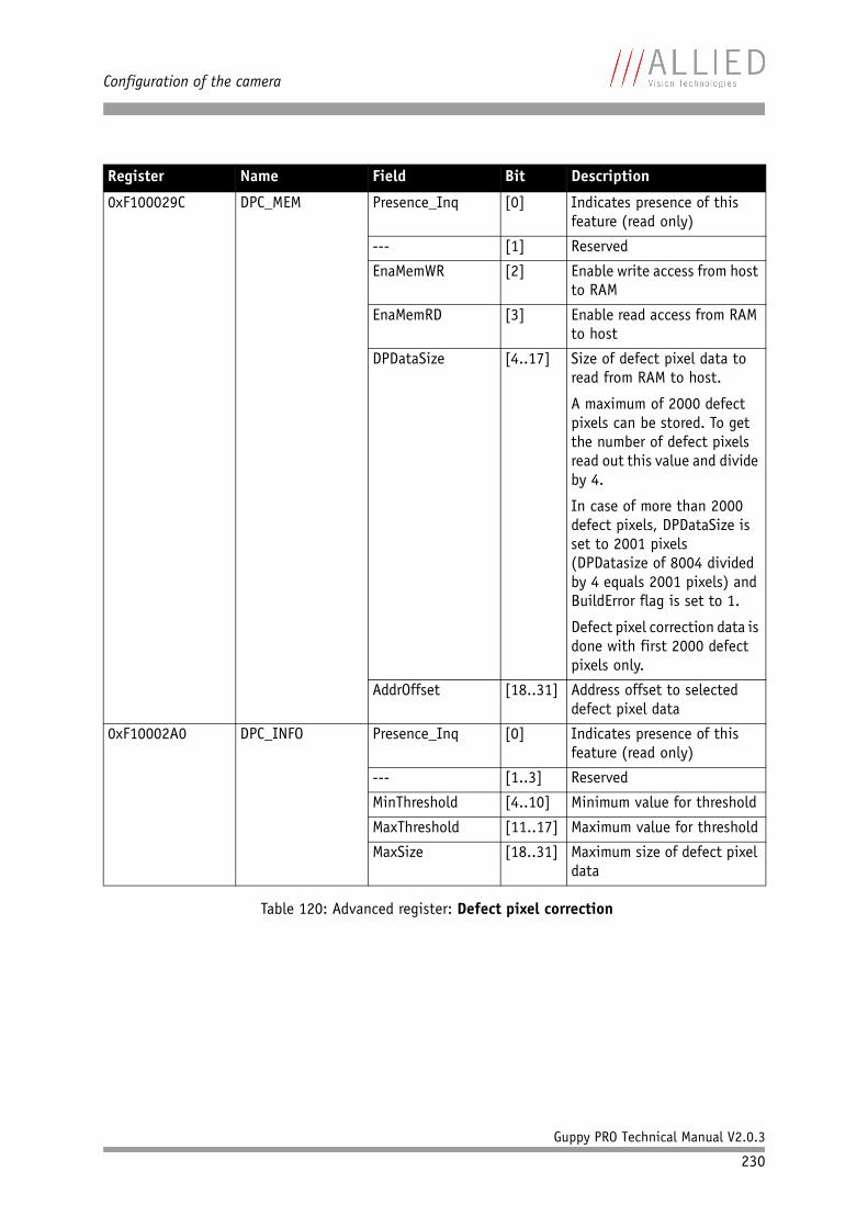
Configuration of the camera
Guppy PRO Technical Manual V2.0.3
230
0xF100029C DPC_MEM Presence_Inq [0] Indicates presence of this feature (read only)
--- [1] Reserved
EnaMemWR [2] Enable write access from host to RAM
EnaMemRD [3] Enable read access from RAM to host
DPDataSize [4..17] Size of defect pixel data to read from RAM to host.
A maximum of 2000 defect pixels can be stored. To get the number of defect pixels read out this value and divide by 4.
In case of more than 2000 defect pixels, DPDataSize is set to 2001 pixels(DPDatasize of 8004 divided by 4 equals 2001 pixels) and BuildError flag is set to 1.
Defect pixel correction data is done with first 2000 defect pixels only.
AddrOffset [18..31] Address offset to selected defect pixel data
0xF10002A0 DPC_INFO Presence_Inq [0] Indicates presence of this feature (read only)
--- [1..3] Reserved
MinThreshold [4..10] Minimum value for threshold
MaxThreshold [11..17] Maximum value for threshold
MaxSize [18..31] Maximum size of defect pixel data
Register Name Field Bit Description
Table 120: Advanced register: Defect pixel correction

Configuration of the camera
Guppy PRO Technical Manual V2.0.3
231
Input/output pin control
Note
• See Chapter Input/output pin control on page 64• See Chapter IO_INP_CTRL 1 on page 65• See Chapter IO_OUTP_CTRL 1-3 on page 70• See Chapter Output modes on page 71
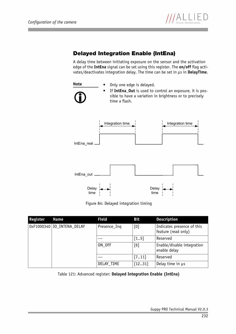
Configuration of the camera
Guppy PRO Technical Manual V2.0.3
232
Delayed Integration Enable (IntEna)A delay time between initiating exposure on the sensor and the activation edge of the IntEna signal can be set using this register. The on/off flag acti-vates/deactivates integration delay. The time can be set in µs in DelayTime.
Note
• Only one edge is delayed.• If IntEna_Out is used to control an exposure, it is pos-
sible to have a variation in brightness or to precisely time a flash.
Figure 84: Delayed integration timing
Register Name Field Bit Description
0xF1000340 IO_INTENA_DELAY Presence_Inq [0] Indicates presence of this feature (read only)
--- [1..5] Reserved
ON_OFF [6] Enable/disable integration enable delay
--- [7..11] Reserved
DELAY_TIME [12..31] Delay time in µs
Table 121: Advanced register: Delayed Integration Enable (IntEna)
Integration time Integration time
IntEna_real
IntEna_out
Delay time
Delay time
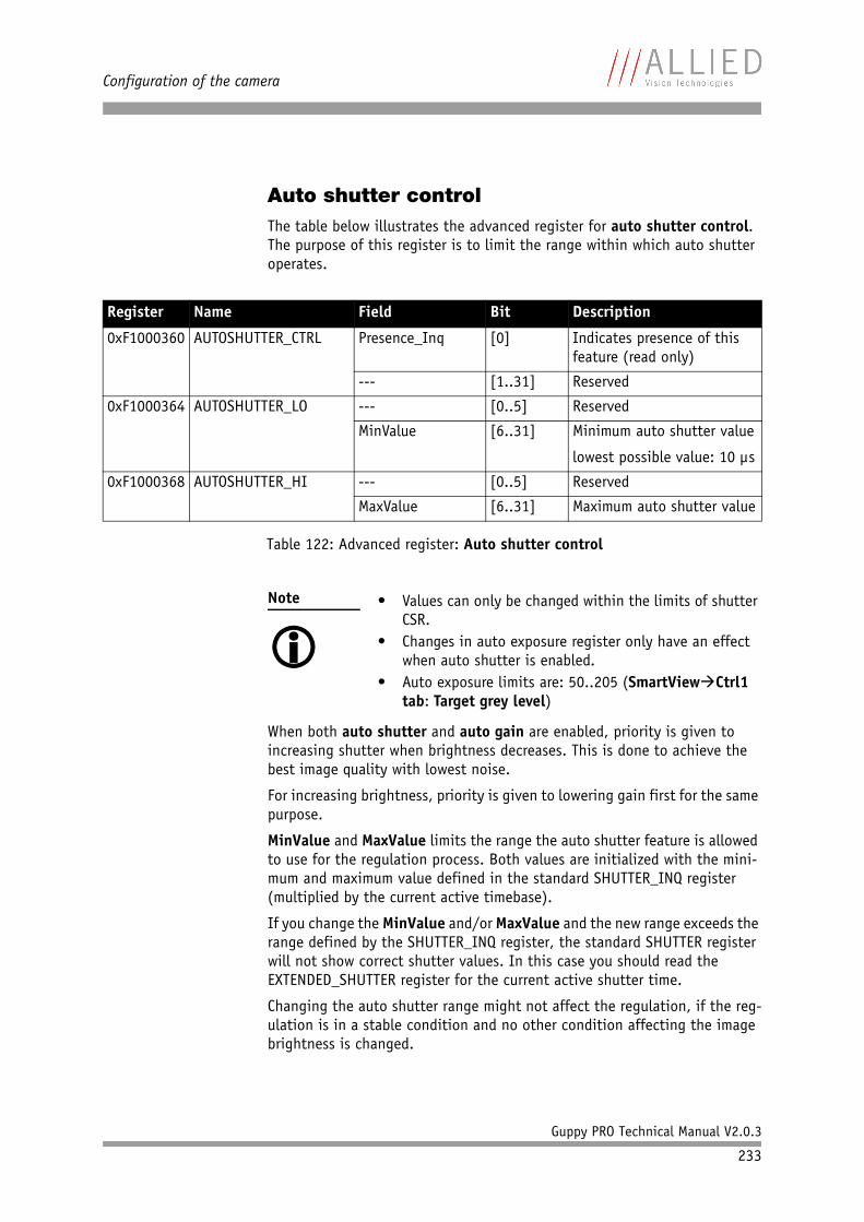
Configuration of the camera
Guppy PRO Technical Manual V2.0.3
233
Auto shutter controlThe table below illustrates the advanced register for auto shutter control. The purpose of this register is to limit the range within which auto shutter operates.
When both auto shutter and auto gain are enabled, priority is given to increasing shutter when brightness decreases. This is done to achieve the best image quality with lowest noise.
For increasing brightness, priority is given to lowering gain first for the same purpose.
MinValue and MaxValue limits the range the auto shutter feature is allowed to use for the regulation process. Both values are initialized with the mini-mum and maximum value defined in the standard SHUTTER_INQ register (multiplied by the current active timebase).
If you change the MinValue and/or MaxValue and the new range exceeds the range defined by the SHUTTER_INQ register, the standard SHUTTER register will not show correct shutter values. In this case you should read the EXTENDED_SHUTTER register for the current active shutter time.
Changing the auto shutter range might not affect the regulation, if the reg-ulation is in a stable condition and no other condition affecting the image brightness is changed.
Register Name Field Bit Description
0xF1000360 AUTOSHUTTER_CTRL Presence_Inq [0] Indicates presence of this feature (read only)
--- [1..31] Reserved
0xF1000364 AUTOSHUTTER_LO --- [0..5] Reserved
MinValue [6..31] Minimum auto shutter value
lowest possible value: 10 µs
0xF1000368 AUTOSHUTTER_HI --- [0..5] Reserved
MaxValue [6..31] Maximum auto shutter value
Table 122: Advanced register: Auto shutter control
Note
• Values can only be changed within the limits of shutter
CSR.• Changes in auto exposure register only have an effect
when auto shutter is enabled.• Auto exposure limits are: 50..205 (SmartViewCtrl1
tab: Target grey level)
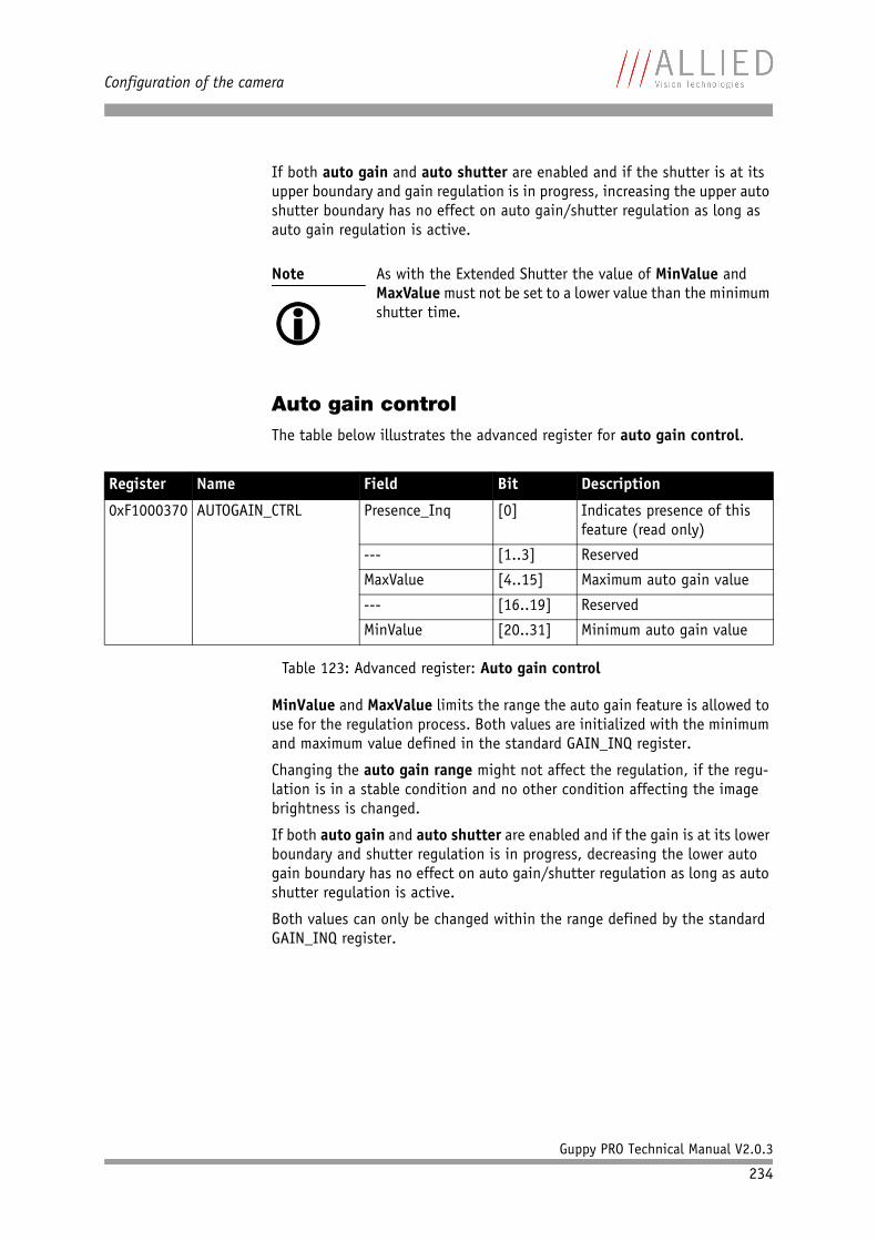
Configuration of the camera
Guppy PRO Technical Manual V2.0.3
234
If both auto gain and auto shutter are enabled and if the shutter is at its upper boundary and gain regulation is in progress, increasing the upper auto shutter boundary has no effect on auto gain/shutter regulation as long as auto gain regulation is active.
Auto gain controlThe table below illustrates the advanced register for auto gain control.
MinValue and MaxValue limits the range the auto gain feature is allowed to use for the regulation process. Both values are initialized with the minimum and maximum value defined in the standard GAIN_INQ register.
Changing the auto gain range might not affect the regulation, if the regu-lation is in a stable condition and no other condition affecting the image brightness is changed.
If both auto gain and auto shutter are enabled and if the gain is at its lower boundary and shutter regulation is in progress, decreasing the lower auto gain boundary has no effect on auto gain/shutter regulation as long as auto shutter regulation is active.
Both values can only be changed within the range defined by the standard GAIN_INQ register.
Note
As with the Extended Shutter the value of MinValue and MaxValue must not be set to a lower value than the minimum shutter time.
Register Name Field Bit Description
0xF1000370 AUTOGAIN_CTRL Presence_Inq [0] Indicates presence of this feature (read only)
--- [1..3] Reserved
MaxValue [4..15] Maximum auto gain value
--- [16..19] Reserved
MinValue [20..31] Minimum auto gain value
Table 123: Advanced register: Auto gain control
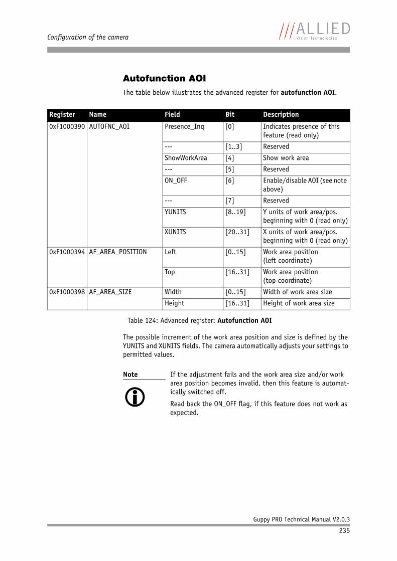
Configuration of the camera
Guppy PRO Technical Manual V2.0.3
235
Autofunction AOIThe table below illustrates the advanced register for autofunction AOI.
The possible increment of the work area position and size is defined by the YUNITS and XUNITS fields. The camera automatically adjusts your settings to permitted values.
Register Name Field Bit Description
0xF1000390 AUTOFNC_AOI Presence_Inq [0] Indicates presence of this feature (read only)
--- [1..3] Reserved
ShowWorkArea [4] Show work area
--- [5] Reserved
ON_OFF [6] Enable/disable AOI (see note above)
--- [7] Reserved
YUNITS [8..19] Y units of work area/pos. beginning with 0 (read only)
XUNITS [20..31] X units of work area/pos. beginning with 0 (read only)
0xF1000394 AF_AREA_POSITION Left [0..15] Work area position(left coordinate)
Top [16..31] Work area position(top coordinate)
0xF1000398 AF_AREA_SIZE Width [0..15] Width of work area size
Height [16..31] Height of work area size
Table 124: Advanced register: Autofunction AOI
Note
If the adjustment fails and the work area size and/or work area position becomes invalid, then this feature is automat-ically switched off.
Read back the ON_OFF flag, if this feature does not work as expected.
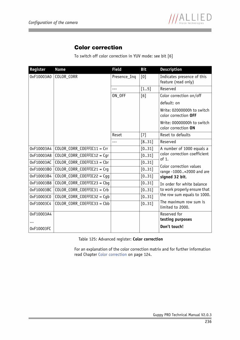
Configuration of the camera
Guppy PRO Technical Manual V2.0.3
236
Color correctionTo switch off color correction in YUV mode: see bit [6]
For an explanation of the color correction matrix and for further information read Chapter Color correction on page 124.
Register Name Field Bit Description
0xF10003A0 COLOR_CORR Presence_Inq [0] Indicates presence of this feature (read only)
--- [1..5] Reserved
ON_OFF [6] Color correction on/off
default: on
Write: 02000000h to switch color correction OFF
Write: 00000000h to switch color correction ON
Reset [7] Reset to defaults
--- [8..31] Reserved
0xF10003A4 COLOR_CORR_COEFFIC11 = Crr [0..31] A number of 1000 equals a color correction coefficient of 1.
Color correction values range -1000..+2000 and are signed 32 bit.
In order for white balance to work properly ensure that the row sum equals to 1000.
The maximum row sum is limited to 2000.
0xF10003A8 COLOR_CORR_COEFFIC12 = Cgr [0..31]
0xF10003AC COLOR_CORR_COEFFIC13 = Cbr [0..31]
0xF10003B0 COLOR_CORR_COEFFIC21 = Crg [0..31]
0xF10003B4 COLOR_CORR_COEFFIC22 = Cgg [0..31]
0xF10003B8 COLOR_CORR_COEFFIC23 = Cbg [0..31]
0xF10003BC COLOR_CORR_COEFFIC31 = Crb [0..31]
0xF10003C0 COLOR_CORR_COEFFIC32 = Cgb [0..31]
0xF10003C4 COLOR_CORR_COEFFIC33 = Cbb [0..31]
0xF10003A4
...
0xF10003FC
Reserved fortesting purposes
Don’t touch!
Table 125: Advanced register: Color correction
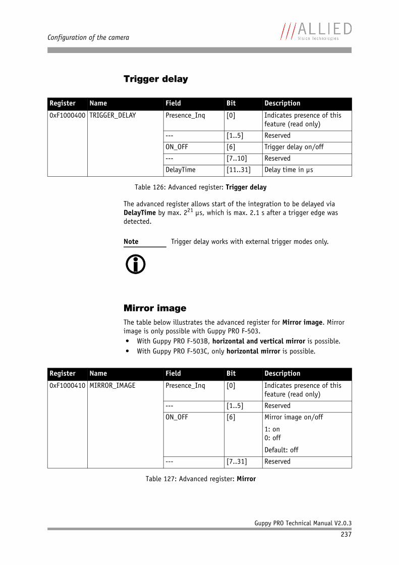
Configuration of the camera
Guppy PRO Technical Manual V2.0.3
237
Trigger delay
The advanced register allows start of the integration to be delayed via DelayTime by max. 221 µs, which is max. 2.1 s after a trigger edge was detected.
Mirror imageThe table below illustrates the advanced register for Mirror image. Mirror image is only possible with Guppy PRO F-503.• With Guppy PRO F-503B, horizontal and vertical mirror is possible.• With Guppy PRO F-503C, only horizontal mirror is possible.
Register Name Field Bit Description
0xF1000400 TRIGGER_DELAY Presence_Inq [0] Indicates presence of this feature (read only)
--- [1..5] Reserved
ON_OFF [6] Trigger delay on/off
--- [7..10] Reserved
DelayTime [11..31] Delay time in µs
Table 126: Advanced register: Trigger delay
Note
Trigger delay works with external trigger modes only.
Register Name Field Bit Description
0xF1000410 MIRROR_IMAGE Presence_Inq [0] Indicates presence of this feature (read only)
--- [1..5] Reserved
ON_OFF [6] Mirror image on/off
1: on0: off
Default: off
--- [7..31] Reserved
Table 127: Advanced register: Mirror
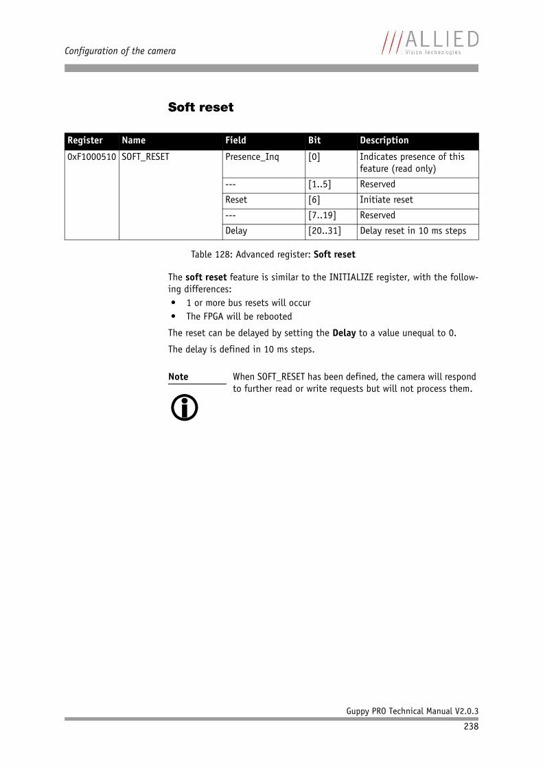
Configuration of the camera
Guppy PRO Technical Manual V2.0.3
238
Soft reset
The soft reset feature is similar to the INITIALIZE register, with the follow-ing differences:• 1 or more bus resets will occur• The FPGA will be rebooted
The reset can be delayed by setting the Delay to a value unequal to 0.
The delay is defined in 10 ms steps.
Register Name Field Bit Description
0xF1000510 SOFT_RESET Presence_Inq [0] Indicates presence of this feature (read only)
--- [1..5] Reserved
Reset [6] Initiate reset
--- [7..19] Reserved
Delay [20..31] Delay reset in 10 ms steps
Table 128: Advanced register: Soft reset
Note
When SOFT_RESET has been defined, the camera will respond to further read or write requests but will not process them.
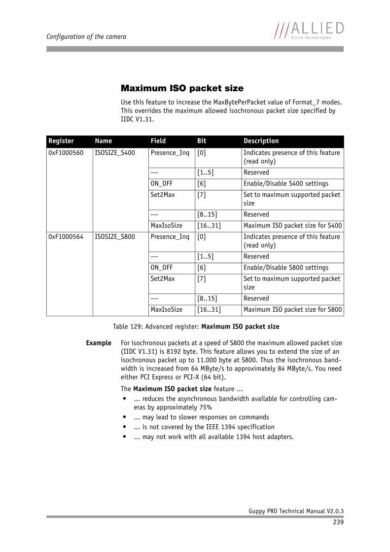
Configuration of the camera
Guppy PRO Technical Manual V2.0.3
239
Maximum ISO packet sizeUse this feature to increase the MaxBytePerPacket value of Format_7 modes. This overrides the maximum allowed isochronous packet size specified by IIDC V1.31.
Example For isochronous packets at a speed of S800 the maximum allowed packet size (IIDC V1.31) is 8192 byte. This feature allows you to extend the size of an isochronous packet up to 11.000 byte at S800. Thus the isochronous band-width is increased from 64 MByte/s to approximately 84 MByte/s. You need either PCI Express or PCI-X (64 bit).
The Maximum ISO packet size feature ...• ... reduces the asynchronous bandwidth available for controlling cam-
eras by approximately 75%• ... may lead to slower responses on commands• ... is not covered by the IEEE 1394 specification• ... may not work with all available 1394 host adapters.
Register Name Field Bit Description
0xF1000560 ISOSIZE_S400 Presence_Inq [0] Indicates presence of this feature (read only)
--- [1..5] Reserved
ON_OFF [6] Enable/Disable S400 settings
Set2Max [7] Set to maximum supported packet size
--- [8..15] Reserved
MaxIsoSize [16..31] Maximum ISO packet size for S400
0xF1000564 ISOSIZE_S800 Presence_Inq [0] Indicates presence of this feature (read only)
--- [1..5] Reserved
ON_OFF [6] Enable/Disable S800 settings
Set2Max [7] Set to maximum supported packet size
--- [8..15] Reserved
MaxIsoSize [16..31] Maximum ISO packet size for S800
Table 129: Advanced register: Maximum ISO packet size
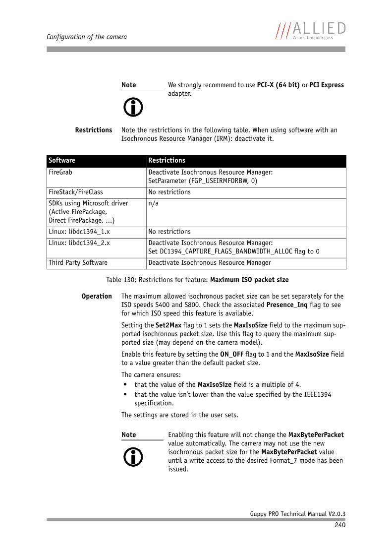
Configuration of the camera
Guppy PRO Technical Manual V2.0.3
240
Restrictions Note the restrictions in the following table. When using software with an Isochronous Resource Manager (IRM): deactivate it.
Operation The maximum allowed isochronous packet size can be set separately for the ISO speeds S400 and S800. Check the associated Presence_Inq flag to see for which ISO speed this feature is available.
Setting the Set2Max flag to 1 sets the MaxIsoSize field to the maximum sup-ported isochronous packet size. Use this flag to query the maximum sup-ported size (may depend on the camera model).
Enable this feature by setting the ON_OFF flag to 1 and the MaxIsoSize field to a value greater than the default packet size.
The camera ensures:• that the value of the MaxIsoSize field is a multiple of 4.• that the value isn’t lower than the value specified by the IEEE1394
specification.
The settings are stored in the user sets.
Note
We strongly recommend to use PCI-X (64 bit) or PCI Express adapter.
Software Restrictions
FireGrab Deactivate Isochronous Resource Manager:SetParameter (FGP_USEIRMFORBW, 0)
FireStack/FireClass No restrictions
SDKs using Microsoft driver (Active FirePackage,Direct FirePackage, ...)
n/a
Linux: libdc1394_1.x No restrictions
Linux: libdc1394_2.x Deactivate Isochronous Resource Manager:Set DC1394_CAPTURE_FLAGS_BANDWIDTH_ALLOC flag to 0
Third Party Software Deactivate Isochronous Resource Manager
Table 130: Restrictions for feature: Maximum ISO packet size
Note
Enabling this feature will not change the MaxBytePerPacket value automatically. The camera may not use the new isochronous packet size for the MaxBytePerPacket value until a write access to the desired Format_7 mode has been issued.
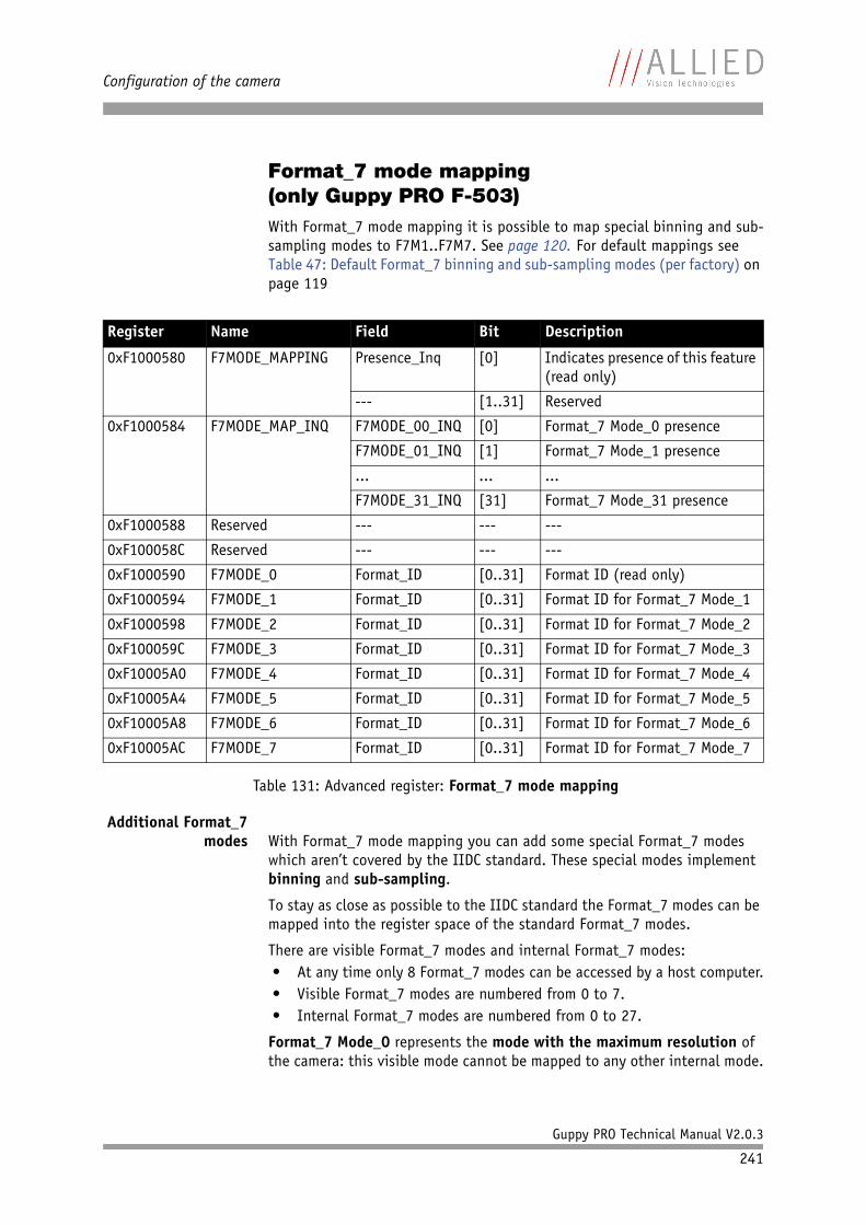
Configuration of the camera
Guppy PRO Technical Manual V2.0.3
241
Format_7 mode mapping(only Guppy PRO F-503)With Format_7 mode mapping it is possible to map special binning and sub-sampling modes to F7M1..F7M7. See page 120. For default mappings see Table 47: Default Format_7 binning and sub-sampling modes (per factory) on page 119
Additional Format_7 modes With Format_7 mode mapping you can add some special Format_7 modes
which aren’t covered by the IIDC standard. These special modes implement binning and sub-sampling.
To stay as close as possible to the IIDC standard the Format_7 modes can be mapped into the register space of the standard Format_7 modes.
There are visible Format_7 modes and internal Format_7 modes:• At any time only 8 Format_7 modes can be accessed by a host computer.• Visible Format_7 modes are numbered from 0 to 7.• Internal Format_7 modes are numbered from 0 to 27.
Format_7 Mode_0 represents the mode with the maximum resolution of the camera: this visible mode cannot be mapped to any other internal mode.
Register Name Field Bit Description
0xF1000580 F7MODE_MAPPING Presence_Inq [0] Indicates presence of this feature (read only)
--- [1..31] Reserved
0xF1000584 F7MODE_MAP_INQ F7MODE_00_INQ [0] Format_7 Mode_0 presence
F7MODE_01_INQ [1] Format_7 Mode_1 presence
... ... ...
F7MODE_31_INQ [31] Format_7 Mode_31 presence
0xF1000588 Reserved --- --- ---
0xF100058C Reserved --- --- ---
0xF1000590 F7MODE_0 Format_ID [0..31] Format ID (read only)
0xF1000594 F7MODE_1 Format_ID [0..31] Format ID for Format_7 Mode_1
0xF1000598 F7MODE_2 Format_ID [0..31] Format ID for Format_7 Mode_2
0xF100059C F7MODE_3 Format_ID [0..31] Format ID for Format_7 Mode_3
0xF10005A0 F7MODE_4 Format_ID [0..31] Format ID for Format_7 Mode_4
0xF10005A4 F7MODE_5 Format_ID [0..31] Format ID for Format_7 Mode_5
0xF10005A8 F7MODE_6 Format_ID [0..31] Format ID for Format_7 Mode_6
0xF10005AC F7MODE_7 Format_ID [0..31] Format ID for Format_7 Mode_7
Table 131: Advanced register: Format_7 mode mapping
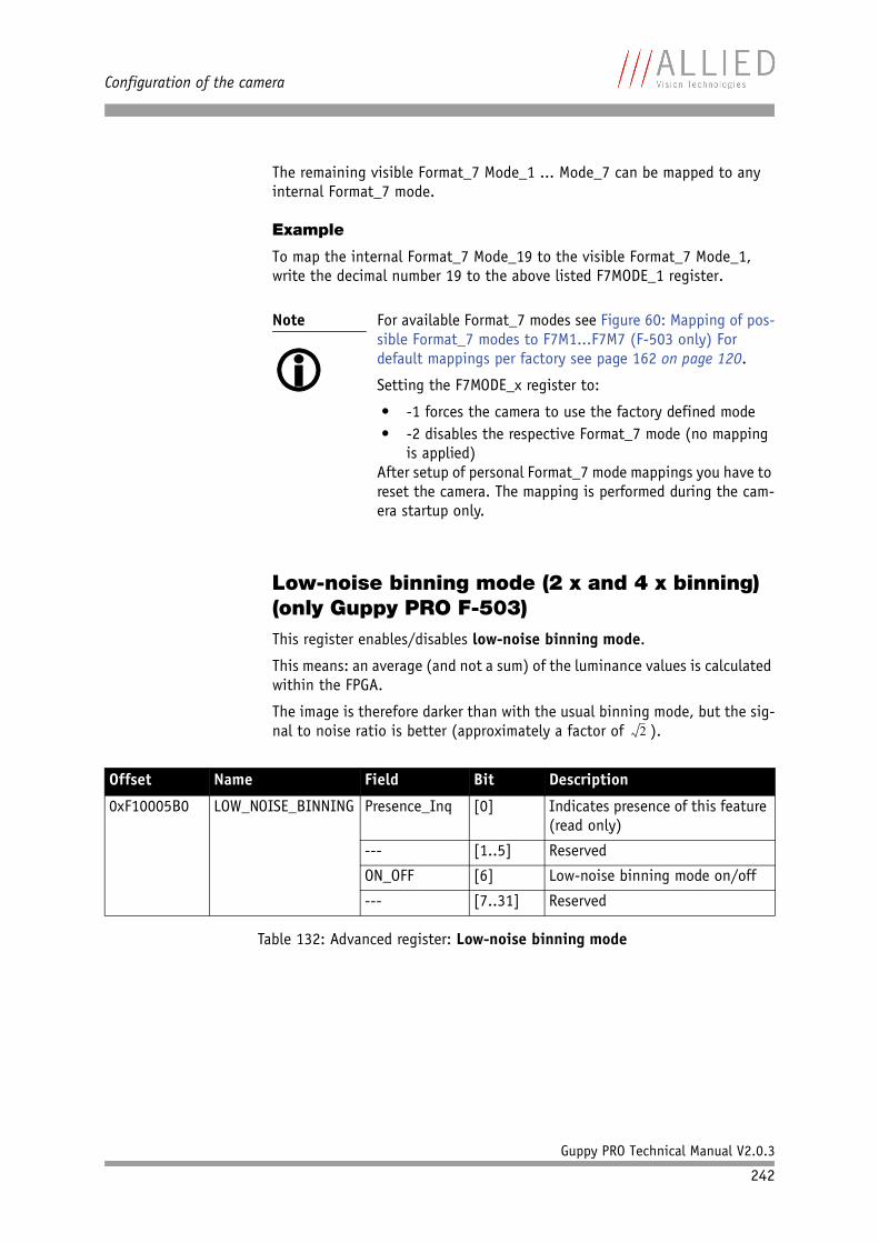
Configuration of the camera
Guppy PRO Technical Manual V2.0.3
242
The remaining visible Format_7 Mode_1 ... Mode_7 can be mapped to any internal Format_7 mode.
Example
To map the internal Format_7 Mode_19 to the visible Format_7 Mode_1, write the decimal number 19 to the above listed F7MODE_1 register.
Low-noise binning mode (2 x and 4 x binning)(only Guppy PRO F-503)This register enables/disables low-noise binning mode.
This means: an average (and not a sum) of the luminance values is calculated within the FPGA.
The image is therefore darker than with the usual binning mode, but the sig-nal to noise ratio is better (approximately a factor of ).
Note
For available Format_7 modes see Figure 60: Mapping of pos-sible Format_7 modes to F7M1...F7M7 (F-503 only) For default mappings per factory see page 162 on page 120.
Setting the F7MODE_x register to:
• -1 forces the camera to use the factory defined mode• -2 disables the respective Format_7 mode (no mapping
is applied)After setup of personal Format_7 mode mappings you have to reset the camera. The mapping is performed during the cam-era startup only.
Offset Name Field Bit Description
0xF10005B0 LOW_NOISE_BINNING Presence_Inq [0] Indicates presence of this feature (read only)
--- [1..5] Reserved
ON_OFF [6] Low-noise binning mode on/off
--- [7..31] Reserved
Table 132: Advanced register: Low-noise binning mode
2
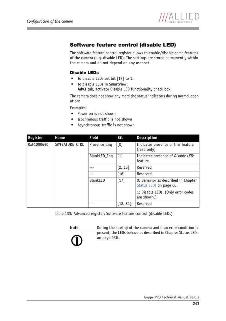
Configuration of the camera
Guppy PRO Technical Manual V2.0.3
243
Software feature control (disable LED)The software feature control register allows to enable/disable some features of the camera (e.g. disable LED). The settings are stored permanently within the camera and do not depend on any user set.
Disable LEDs• To disable LEDs set bit [17] to 1.• To disable LEDs in SmartView:
Adv3 tab, activate Disable LED functionality check box.
The camera does not show any more the status indicators during normal oper-ation:
Examples:• Power on is not shown• Isochronous traffic is not shown• Asynchronous traffic is not shown
Register Name Field Bit Description
0xF1000640 SWFEATURE_CTRL Presence_Inq [0] Indicates presence of this feature (read only)
BlankLED_Inq [1] Indicates presence of Disable LEDs feature.
--- [2..15] Reserved
--- [16] Reserved
BlankLED [17] 0: Behavior as described in Chapter Status LEDs on page 60.
1: Disable LEDs. (Only error codes are shown.)
--- [18..31] Reserved
Table 133: Advanced register: Software feature control (disable LEDs)
Note
During the startup of the camera and if an error condition is present, the LEDs behave as described in Chapter Status LEDs on page 93ff.
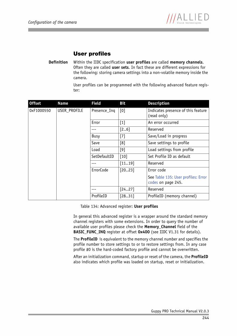
Configuration of the camera
Guppy PRO Technical Manual V2.0.3
244
User profilesDefinition Within the IIDC specification user profiles are called memory channels.
Often they are called user sets. In fact these are different expressions for the following: storing camera settings into a non-volatile memory inside the camera.
User profiles can be programmed with the following advanced feature regis-ter:
In general this advanced register is a wrapper around the standard memory channel registers with some extensions. In order to query the number of available user profiles please check the Memory_Channel field of the BASIC_FUNC_INQ register at offset 0x400 (see IIDC V1.31 for details).
The ProfileID is equivalent to the memory channel number and specifies the profile number to store settings to or to restore settings from. In any case profile #0 is the hard-coded factory profile and cannot be overwritten.
After an initialization command, startup or reset of the camera, the ProfileID also indicates which profile was loaded on startup, reset or initialization.
Offset Name Field Bit Description
0xF1000550 USER_PROFILE Presence_Inq [0] Indicates presence of this feature (read only)
Error [1] An error occurred
--- [2..6] Reserved
Busy [7] Save/Load in progress
Save [8] Save settings to profile
Load [9] Load settings from profile
SetDefaultID [10] Set Profile ID as default
--- [11..19] Reserved
ErrorCode [20..23] Error code
See Table 135: User profiles: Error codes on page 245.
--- [24..27] Reserved
ProfileID [28..31] ProfileID (memory channel)
Table 134: Advanced register: User profiles
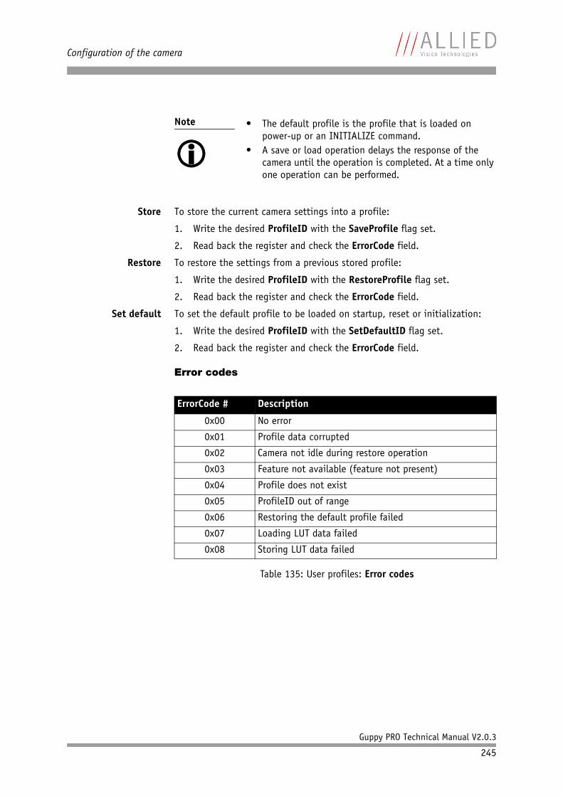
Configuration of the camera
Guppy PRO Technical Manual V2.0.3
245
Store To store the current camera settings into a profile:
1. Write the desired ProfileID with the SaveProfile flag set.
2. Read back the register and check the ErrorCode field.
Restore To restore the settings from a previous stored profile:
1. Write the desired ProfileID with the RestoreProfile flag set.
2. Read back the register and check the ErrorCode field.
Set default To set the default profile to be loaded on startup, reset or initialization:
1. Write the desired ProfileID with the SetDefaultID flag set.
2. Read back the register and check the ErrorCode field.
Error codes
Note
• The default profile is the profile that is loaded on
power-up or an INITIALIZE command.• A save or load operation delays the response of the
camera until the operation is completed. At a time only one operation can be performed.
ErrorCode # Description
0x00 No error
0x01 Profile data corrupted
0x02 Camera not idle during restore operation
0x03 Feature not available (feature not present)
0x04 Profile does not exist
0x05 ProfileID out of range
0x06 Restoring the default profile failed
0x07 Loading LUT data failed
0x08 Storing LUT data failed
Table 135: User profiles: Error codes
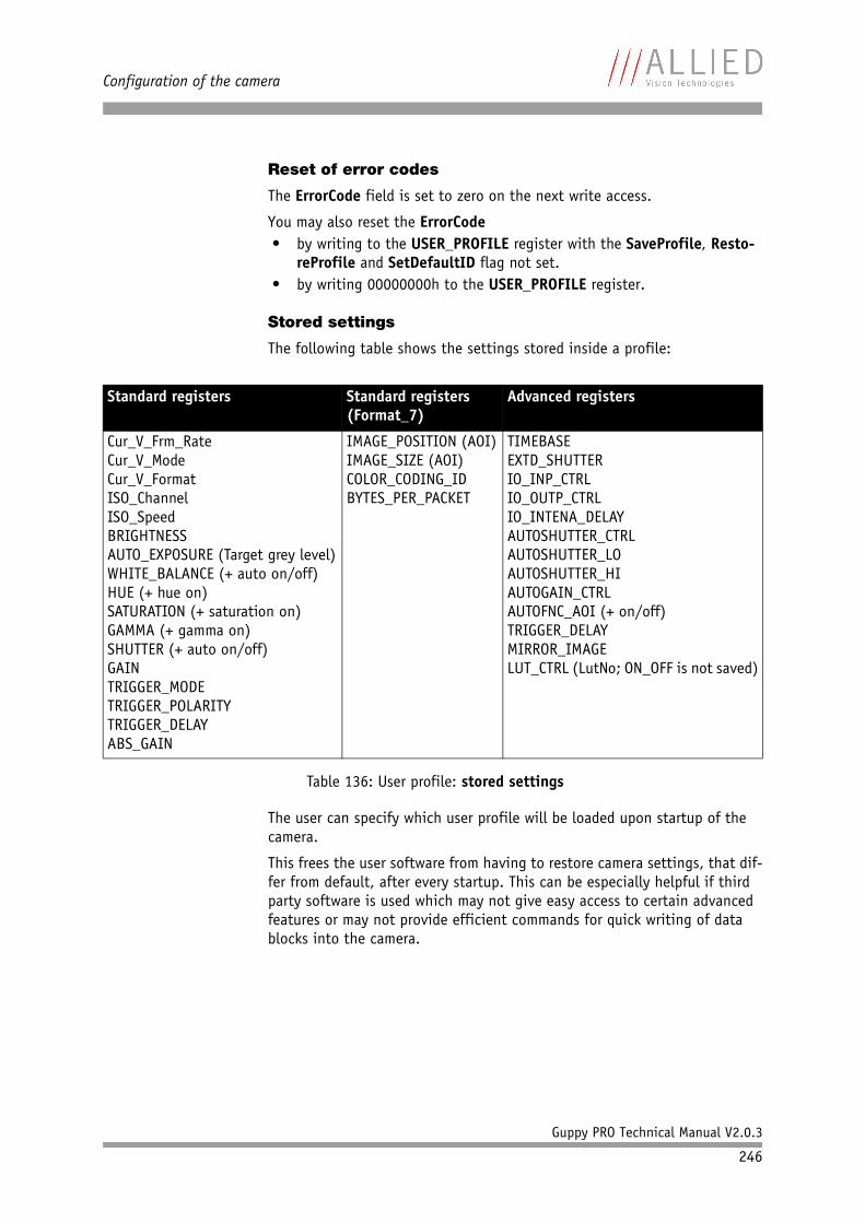
Configuration of the camera
Guppy PRO Technical Manual V2.0.3
246
Reset of error codes
The ErrorCode field is set to zero on the next write access.
You may also reset the ErrorCode• by writing to the USER_PROFILE register with the SaveProfile, Resto-
reProfile and SetDefaultID flag not set.• by writing 00000000h to the USER_PROFILE register.
Stored settings
The following table shows the settings stored inside a profile:
The user can specify which user profile will be loaded upon startup of the camera.
This frees the user software from having to restore camera settings, that dif-fer from default, after every startup. This can be especially helpful if third party software is used which may not give easy access to certain advanced features or may not provide efficient commands for quick writing of data blocks into the camera.
Standard registers Standard registers(Format_7)
Advanced registers
Cur_V_Frm_RateCur_V_ModeCur_V_FormatISO_ChannelISO_SpeedBRIGHTNESSAUTO_EXPOSURE (Target grey level)WHITE_BALANCE (+ auto on/off)HUE (+ hue on)SATURATION (+ saturation on)GAMMA (+ gamma on)SHUTTER (+ auto on/off)GAINTRIGGER_MODETRIGGER_POLARITYTRIGGER_DELAYABS_GAIN
IMAGE_POSITION (AOI)IMAGE_SIZE (AOI)COLOR_CODING_IDBYTES_PER_PACKET
TIMEBASEEXTD_SHUTTERIO_INP_CTRLIO_OUTP_CTRLIO_INTENA_DELAYAUTOSHUTTER_CTRLAUTOSHUTTER_LOAUTOSHUTTER_HIAUTOGAIN_CTRLAUTOFNC_AOI (+ on/off)TRIGGER_DELAYMIRROR_IMAGELUT_CTRL (LutNo; ON_OFF is not saved)
Table 136: User profile: stored settings
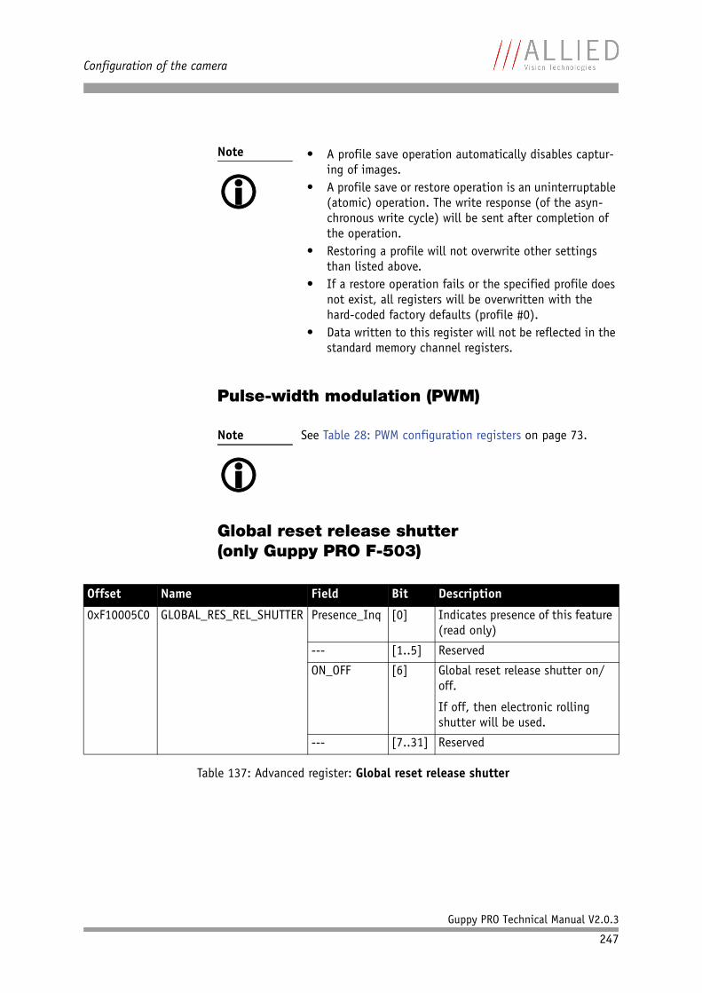
Configuration of the camera
Guppy PRO Technical Manual V2.0.3
247
Pulse-width modulation (PWM)
Global reset release shutter(only Guppy PRO F-503)
Note
• A profile save operation automatically disables captur-
ing of images.• A profile save or restore operation is an uninterruptable
(atomic) operation. The write response (of the asyn-chronous write cycle) will be sent after completion of the operation.
• Restoring a profile will not overwrite other settings than listed above.
• If a restore operation fails or the specified profile does not exist, all registers will be overwritten with the hard-coded factory defaults (profile #0).
• Data written to this register will not be reflected in the standard memory channel registers.
Note
See Table 28: PWM configuration registers on page 73.
Offset Name Field Bit Description
0xF10005C0 GLOBAL_RES_REL_SHUTTER Presence_Inq [0] Indicates presence of this feature (read only)
--- [1..5] Reserved
ON_OFF [6] Global reset release shutter on/off.
If off, then electronic rolling shutter will be used.
--- [7..31] Reserved
Table 137: Advanced register: Global reset release shutter
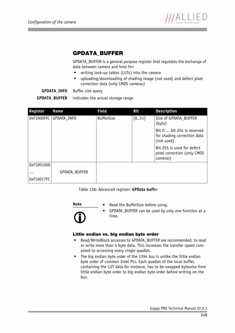
Configuration of the camera
Guppy PRO Technical Manual V2.0.3
248
GPDATA_BUFFERGPDATA_BUFFER is a general purpose register that regulates the exchange of data between camera and host for:• writing look-up tables (LUTs) into the camera• uploading/downloading of shading image (not used) and defect pixel
correction data (only CMOS cameras)
GPDATA_INFO Buffer size query
GPDATA_BUFFER indicates the actual storage range
Little endian vs. big endian byte order• Read/WriteBlock accesses to GPDATA_BUFFER are recommended, to read
or write more than 4 byte data. This increases the transfer speed com-pared to accessing every single quadlet.
• The big endian byte order of the 1394 bus is unlike the little endian byte order of common Intel PCs. Each quadlet of the local buffer, containing the LUT data for instance, has to be swapped bytewise from little endian byte order to big endian byte order before writing on the bus.
Register Name Field Bit Description
0xF1000FFC GPDATA_INFO BufferSize [0..31] Size of GPDATA_BUFFER (byte)
Bit 0 ... bit 254 is reserved for shading correction data (not used)
Bit 255 is used for defect pixel correction (only CMOS cameras)
0xF1001000
…
0xF10017FC
GPDATA_BUFFER
Table 138: Advanced register: GPData buffer
Note
• Read the BufferSize before using.• GPDATA_BUFFER can be used by only one function at a
time.
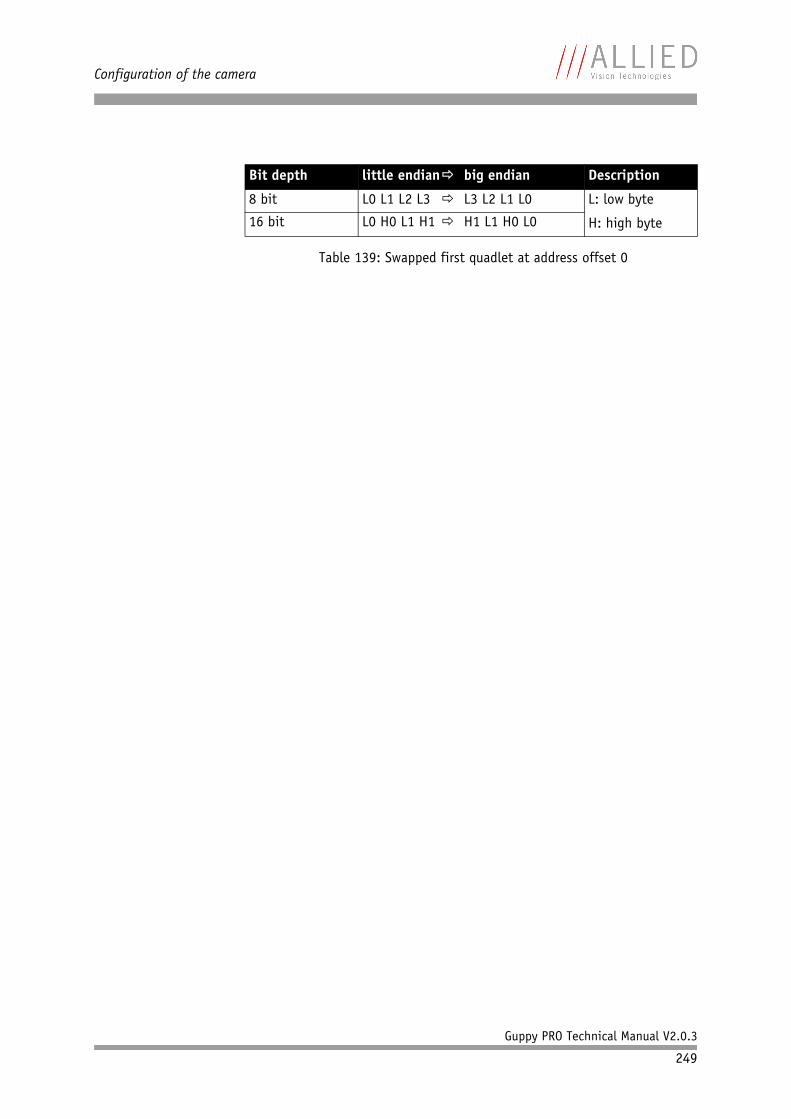
Configuration of the camera
Guppy PRO Technical Manual V2.0.3
249
Bit depth little endian big endian Description
8 bit L0 L1 L2 L3 L3 L2 L1 L0 L: low byte
H: high byte16 bit L0 H0 L1 H1 H1 L1 H0 L0
Table 139: Swapped first quadlet at address offset 0
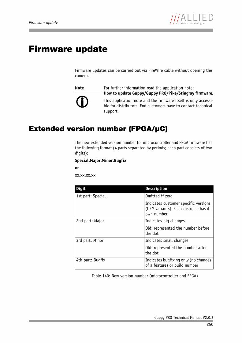
Firmware update
Guppy PRO Technical Manual V2.0.3
250
Firmware update
Firmware updates can be carried out via FireWire cable without opening the camera.
Extended version number (FPGA/µC)
The new extended version number for microcontroller and FPGA firmware has the following format (4 parts separated by periods; each part consists of two digits):
Special.Major.Minor.Bugfix
or
xx.xx.xx.xx
Note
For further information read the application note:How to update Guppy/Guppy PRO/Pike/Stingray firmware.
This application note and the firmware itself is only accessi-ble for distributors. End customers have to contact technical support.
Digit Description
1st part: Special Omitted if zero
Indicates customer specific versions (OEM variants). Each customer has its own number.
2nd part: Major Indicates big changes
Old: represented the number before the dot
3rd part: Minor Indicates small changes
Old: represented the number after the dot
4th part: Bugfix Indicates bugfixing only (no changes of a feature) or build number
Table 140: New version number (microcontroller and FPGA)
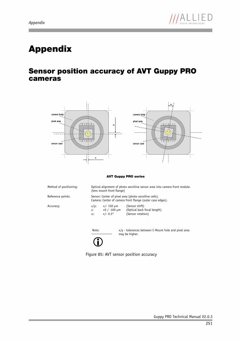
Appendix
Guppy PRO Technical Manual V2.0.3
251
Appendix
Sensor position accuracy of AVT Guppy PRO cameras
Figure 85: AVT sensor position accuracy
x
ycamera body
sensor case
pixel area
x
ycamera body
sensor case
pixel area
sensor case
�
camera body
pixel area
sensor case
�
camera body
pixel area
AVT Guppy PRO series
Method of positioning: Optical alignment of photo sensitive sensor area into camera front module.
(lens mount front flange)
Reference points: Sensor: Center of pixel area (photo sensitive cells). Camera: Center of camera front flange (outer case edges).
Accuracy: x/y: +/- 150 μm (Sensor shift) z: +0 / -100 μm (Optical back focal length) �: +/- 0.5° (Sensor rotation)
Note:
� x/y - tolerances between C-Mount hole and pixel area may be higher.
Guppy PRO Technical Manual V2.0.3
252
Index
Index
Numbers
0xF1000010 (version info) .......................2170xF1000040 (advanced feature inquiry)......2200xF1000100 (camera status) .....................2220xF1000200 (max. resolution) ..................2230xF1000208 (time base) ..........................2230xF100020C (extended shutter)..........143, 2250xF1000210 (test image) .........................2260xF1000240 (LUT)...................................2270xF1000298 (DPC_CTRL)...........................2290xF1000300 (input control)....................... 640xF1000340 (Delayed IntEna) ...................2320xF1000360 (auto shutter control) ............2330xF1000370 (auto gain control) ................2340xF1000390 (autofunction AOI) ................2350xF10003A0 (color correction) ..................2360xF1000400 (trigger delay) ......................2370xF1000410 (mirror image) ......................2370xF1000510 (soft reset)...........................2380xF1000550 (user profiles/memory channels/user sets) ..............................................2440xF1000560 (Max. ISO size S400) ..............2390xF1000564 (Max. ISO size S800) ..............2390xF10005B0 (low- noise binning mode)......2420xF10005C0 (global reset release shutter)...2470xF1000840 (debounce)...........................1400xF1000FFC (GPData buffer)......................2481394a data transmission ........................... 201394b
bandwidths ....................................... 25requirements laptop............................ 26
1394b data transmission ........................... 212 out of 4 H+V sub-sampling (b/w)
drawing ...........................................1162 out of 4 H+V sub-sampling (color)
drawing ...........................................1182 out of 8 H+V sub-sampling (b/w)
drawing ...........................................1172 out of 8 H+V sub-sampling (color)
drawing ...........................................118
A
Abs_Control (Field) .............. 85, 90, 92, 93, 95
Abs_Control_Inq (Field) ............................ 66access
binning and sub-sampling ..................118AccessLutNo (Field).................................227Access_Control_Register ..........................203accuracy
sensor position .................................251AddrOffset (Field) ...................................227Advanced feature inquiry .........................220Advanced feature inquiry (advanced register)...220Advanced features...................................215
activate ...........................................217base address.....................................203inquiry.............................................201
advanced registerAdvanced feature inquiry....................220Auto gain control ..............................234Auto shutter control ..........................233Autofunction AOI ..............................235Camera status ...................................222Color correction ................................236defect pixel correction .......................229Delayed Integration Enable (IntEna) ....232Extended shutter........................ 143, 225Extended version...............................217Format_7 mode mapping ....................241global reset release shutter.................247GPData buffer ...................................248Input control..................................... 64low-noise binning mode .....................242LUT .................................................227Max. ISO packet ................................239Max. resolution .................................223Mirror ..............................................237Mirror image.....................................237Output control ................................... 70Soft reset .........................................238Test images ......................................226Time base.........................................223Trigger delay ....................................237User profiles .....................................244
AOI.......................................................163area of interest (AOI) ..............................165
Guppy PRO Technical Manual V2.0.3
253
Index
asynchronous broadcast ...........................147auto exposure
limits ..............................................233target grey level...........................94, 233
Auto Exposure (CSR register) ..................... 93auto gain..........................................91, 233Auto gain control (advanced register) ........234auto shutter................................ 88, 89, 233Auto shutter control (advanced register) ....233auto white balance................................... 88
external trigger .................................. 88AUTOFNC_AOI....................................88, 235AUTOFNC_AOI positioning ......................... 89Autofunction AOI (advanced register) ........235AUTOGAIN_CTRL......................................234AUTOSHUTTER_CTRL ................................233AUTOSHUTTER_HI ...................................233AUTOSHUTTER_LO ...................................233AUTO_EXPOSURE ...................................... 93Auto_Inq ................................................ 66AVT sensor position accuracy ....................251A_M_MODE (Field)................ 85, 90, 92, 93, 95
B
bandwidth .............................................150affect frame rate ...............................178available ..........................................167frame rates.......................................166RGB8 format .....................................126save in RAW-mode .............................122
BAYER demosaicing ..........................122, 124BAYER mosaic.........................................122BAYER to RGB
color interpretation ...........................122binning .................................................105
access..............................................118full..................................................111horizontal ........................................109only Guppy PRO b/w ..........................105vertical ............................................106
BitsPerValue...........................................227black level .............................................. 94black value ............................................. 94black/white camera
block diagram .................................... 82blink codes ............................................. 61block diagram
b/w camera ....................................... 82
color camera...................................... 83block diagrams
cameras ............................................ 82BOSS...................................................... 21BRIGHTNESS......................................95, 209Brightness
inquiry register .................................202brightness
auto shutter ...................................... 89average............................................. 91decrease ..........................................233IIDC register...................................... 95increase ......................................94, 233LUT .................................................. 97nonlinear .......................................... 97reference ..................................... 89, 91setting ............................................. 94sub-sampling ....................................113variation ..........................................232
Brightness Control ..................................202Brightness (CSR register) .......................... 95BRIGHTNESS_INQUIRY .............................204Brightness_inq. ......................................204buffer
LUT .................................................. 99BuildDPData flag.....................................103
advanced register ..............................229bulk trigger.....................................129, 134bulk trigger (Trigger_Mode_15).................134bus owner supervisor selector (BOSS).......... 21busy signal ............................................. 68Bus_Id ..................................................182
C
camera dimensions................................... 542 x 1394b copper ............................... 54
camera interfaces..................................... 58camera lenses.......................................... 32Camera status (advanced register) .............222cameras
block diagram .................................... 82CAMERA_STATUS .....................................222Camera_Status_Register ...........................182CE ......................................................... 18channel .................................................. 76color camera
block diagram .................................... 83color coding...........................................121
Guppy PRO Technical Manual V2.0.3
254
Index
color codings .........................................121color correction ...............................124, 125
AVT cameras .....................................124formula............................................124why? ...............................................124
Color correction (advanced register) ..........236color information....................................122Color_Coding..........................................121COLOR_CODING_INQ ................................121common GND
inputs............................................... 59common vcc
outputs............................................. 59continuous
using Trigger_Mode_15 ......................136controlling
image capture...................................127CSR.......................................................182
shutter ............................................. 90CSR register
Auto Exposure.................................... 93Brightness......................................... 95GAIN ................................................ 92
D
data block packet format........................... 76description ........................................ 76
data exchange bufferLUT .................................................. 99
data packets ........................................... 76data path................................................ 82data payload size ...............................25, 178data_length ............................................ 76DCAM ........................................16, 150, 182debounce time
for input ports ..................................140debounce time for trigger ........................139declaration of conformity .......................... 18defect pixel correction
advanced register ..............................229build and store .................................102building defect pixel data...................102calculated mean value........................229max. 2000 defect pixels......................230mechanisms......................................100
defect pixel correction (advanced register) .229defect pixel correction (DPC) ....................229
Delayed Integration Enable (IntEna) (advanced register) ................................................232DelayTime..............................................232Digital Camera Specification (DCAM) ..........182digital video information .......................... 76digitizer ................................................. 98document history..................................... 10DPC (defect pixel correction) ....................229DPC_CTRL ..............................................229DPC_INFO ..............................................230DPC_MEM...............................................230DPDataSize
defect pixel data size (max. 2000) .......230
E
edge mode (Trigger_Mode_0) ..............68, 129effective min. exp. time...........................142electronic rolling shutter (ERS) .................128EnableMemWR (Field) ..............................227End of exposure......................................146error code
user profiles .....................................245error codes
LED .................................................. 62error states ............................................. 61ERS (=electronic rolling shutter) ...............128ExpOffset...............................................224Exposure time
(Field) .............................................143exposure time ........................................141
81 Ch register ...................................143example ...........................................142extended shutter...............................225formula............................................141longest ............................................143long-term integration ........................142minimum .........................................142
ExpressCard............................................. 27technology ........................................ 27
ExpressCard/54........................................ 27ExpTime (Field) ......................................143EXTD_SHUTTER .......................................225extended shutter ....................................142
FireDemo..........................................225FireView...........................................225inactive .................................... 143, 225register............................................225trigger mode ....................................129
Guppy PRO Technical Manual V2.0.3
255
Index
Extended shutter (advanced register)..143, 225Extended version (advanced register).........217EXTENDED_SHUTTER..........................141, 142External GND ........................................... 59external trigger ....................................... 63
F
FCC Class B.............................................. 18FireDemo
extended shutter ...............................225FireView
extended shutter ...............................225FireWire
connecting capabilities ....................... 21definition.......................................... 19serial bus .......................................... 20
FireWire 400............................................ 22FireWire 800............................................ 22firmware update ..............................250, 251flash .....................................................128focal length ............................................ 32focal width
MF-033/046/145/146.......................... 33Format_7 mode mapping (advanced register) ....241Format_7 modes
mapping ..........................................120formula
color correction.................................124frame rates ............................................150
bandwidth........................................166bus speed.........................................150Format_7 .........................................170maximum .........................................150tables ..............................................166video mode 0....................................169video mode 2....................................169
Frame valid ............................................. 68free-run.................................................147full binning............................................111Fval ....................................................... 68Fval signal .............................................. 68
G
gainauto ................................................. 91auto exposure CSR .............................. 91
AUTOFNC_AOI .................................... 88manual ............................................. 94manual gain range.............................. 94ranges .............................................. 94
gain CSR................................................. 94GAIN (CSR register) .................................. 92GAIN (name) ........................................... 92GAIN (register) ........................................ 86gamma function ...................................... 97gamma LUT ............................................. 97global reset release shutter (GRR)
advanced register ..............................247description.......................................128
global shutter ........................................127GPData buffer (advanced register) .............248GPDATA_BUFFER ...................................... 99GRR (global reset release shutter)
description.......................................128Guppy PRO F-031B/C fiber (Specification).... 35Guppy PRO F-031B/C (Specification) ........... 35Guppy PRO F-032B/C fiber (Specification).... 37Guppy PRO F-032B/C (Specification) ........... 37Guppy PRO F-125B/C (Specification) ........... 39Guppy PRO F-146B (Specification) .............. 41Guppy PRO F-201B/C (Specification) ........... 43Guppy PRO F-503B/C (Specification) ........... 45Guppy PRO types...................................... 17
H
hardware trigger ................................67, 138horizontal binning ..................................109horizontal sub-sampling (b/w)
drawing ...........................................113horizontal sub-sampling (color)
drawing ...........................................114hue.......................................................123
offset ..............................................123
I
IDcolor coding .....................................121
IEEE 1394 ............................................... 16IEEE 1394 standards................................. 19IEEE 1394 Trade Association.....................182IEEE 1394b connector............................... 58IIDC..........................................16, 150, 182
data structure ............................... 79, 80
Guppy PRO Technical Manual V2.0.3
256
Index
isochronous data block packet format.... 76pixel data.......................................... 76trigger delay...................................... 66video data format............................... 77YUV 4:1:1..................................... 77, 78YUV 4:2:2..................................... 77, 78
IIDC V1.31 .............................................127IIDC V1.31 camera control standards........... 23image capture
controlling .......................................127IMAGE_POSITION ....................................163IMAGE_SIZE ...........................................163input
block diagram .................................... 63signals.............................................. 63
Input control (advanced register)............... 64input mode ............................................. 65InputMode (Field) .................................... 64inputs
common GND ..................................... 59general ............................................. 63in detail............................................ 63triggers............................................. 63
input/output pin control..........................231inquiry
trigger source 0.................................205Inquiry register
basic function...................................201Integration Enable signal .......................... 68IntEna............................................... 59, 72IntEna signal ....................................68, 232IntEna_Delay........................................... 73IntEna_Out ............................................232internal trigger................................129, 134interpolation
BAYER demosaicing ....................122, 123BAYER to RGB ...................................122color ...............................................122
IO_INP_CTRL1 ......................................... 64IO_OUTP_CTRL1 ....................................... 70IO_OUTP_CTRL2 ....................................... 70IO_OUTP_CTRL3 ....................................... 70isochronous blocks ................................... 76isochronous channel number ..................... 76isochronous data block packet format ......... 76isochronous data packets .......................... 76Isochronous Resource Manager (IRM).........240IsoEnable
white balance .................................... 87
ISO_Enable ............................................147ISO_Enable mode....................................147
multi-shot........................................147one-shot ..........................................144
J
jitter..............................................146, 148at exposure start ...............................149
L
latching connectors.................................. 58LCD shutter ............................................133LED
error codes ........................................ 62indication ......................................... 61status............................................... 60
Legal notice.............................................. 2level mode (Trigger_Mode_1)....................129look-up table (LUT) ............................97, 227
user-defined ...................................... 97low-noise binning mode (advanced register) ....242LUT.......................................................227
data exchange buffer .......................... 99example ............................................ 97gamma ............................................. 97general ............................................. 97loading into camera............................ 99volatile ............................................. 98
LUT (advanced register) ...........................227LutNo....................................................227LutNo (Field)..........................................227LUT_CTRL...............................................227LUT_INFO ..............................................227LUT_MEM_CTRL.......................................227
M
Manual_Inq............................................. 66Maximum resolution (Register) .................223MaxLutSize (Field) ..................................227MaxResolution (Field) ..............................220MaxSize (Field) .......................................230MaxValue ...............................................234MAX_RESOLUTION ...................................223Max_Value .............................................. 66Max. ISO packet (advanced register) ..........239Max. resolution (advanced register) ...........223
Guppy PRO Technical Manual V2.0.3
257
Index
Meandefect pixel mean value......................229
mechanical shutter..................................133memory channels ....................................244memory channels (user profiles)................244Micron/Aptina CMOS sensor ......................128minimum exposure time...........................142MinValue ...............................................234Min_Value............................................... 66Min. exp. time + offset ............................142Mirror image (advanced register)...............237Mirror (advanced register) ........................237MSB aligned ............................................ 76multi-shot .............................................147
external trigger .................................147using Trigger_Mode_15 ......................136
N
Node_Id ................................................182NumOfLuts .............................................227NumOfLuts (Field) ...................................227
O
OFFSETautomatic white balance ..................... 86
offset....................................................141800h ................................................ 95CCD .................................................. 94configuration ROM.............................187factors .............................................187hue .................................................123initialize register...............................190inquiry register video format ...............190inquiry register video mode.................191saturation ........................................123setting brightness .............................. 94setting gain....................................... 94
one-push white balance ....................... 86, 87one-shot................................................144
Trigger_Mode_15........................129, 134using Trigger_Mode_15 ......................136values..............................................145
one-shot bit...........................................144one-shot mode .......................................144One_Push (Field) ................. 85, 90, 92, 93, 95One_Push_Inq ......................................... 66ON_OFF .................................................. 66
ON_OFF (Field) ........................................ 85optocoupler ............................................ 63output
block diagram .................................... 69signals.............................................. 68
Output control (advanced register) ............. 70output impulse diagram
WaitingForTrigger ............................... 72output mode ........................................... 70
ID .................................................... 71Output mode (Field) ................................. 70output pin control ................................... 71outputs .................................................. 68
common vcc ...................................... 59general ............................................. 63registers ........................................... 70set by software .................................. 73
OutVCC ................................................... 59
P
Packed 12-Bit Mode ................................121Packed 12-Bit MONO................................121Packed 12-Bit RAW..................................121packet format.......................................... 76PI controller ........................................... 91pin control.............................................231PinState flag ........................................... 70PinState (Field) ....................................... 64pixel data ............................................... 76plus integral controller ............................. 91Polarity (Field) ................................... 64, 70Power
IEEE 1394b........................................ 58power
GND ................................................. 59presence
trigger source 0 ................................205Presence_Inq .......................................... 64Presence_Inq (Field) ........................... 66, 85programmable mode (Trigger_Mode_15) .....129pulse-width modulation
signal ............................................... 68PulseWidthMod signal............................... 68
R
read valuetrigger input.....................................205
Guppy PRO Technical Manual V2.0.3
258
Index
Readout_Inq ........................................... 66RGB to YUV
formula............................................126RGB8 format...........................................126RoHS (2002/95/EC) .................................. 18row time
Guppy PRO F-503...............................141
S
saturation..............................................123offset ..............................................123
sensor position accuracy ..........................251sequence
loading a LUT .................................... 99one-push white balance....................... 87OneShot...........................................144
SHUTTER................................................. 90Shutter CSR............................................. 90shutter time
formula............................................141SHUTTER_MODES .....................................127signal-to noise ratio (SNR)
vertical binning.................................107signal-to-noise ratio (SNR).......................105signal-to-noise separation........................105SNR ......................................................105Soft reset (advanced register) ...................238software trigger ......................................139Software_Trigger (CSR) ............................207specifications.......................................... 35spectral sensitivity
Guppy PRO F-031B.............................. 48Guppy PRO F-031C .............................. 48Guppy PRO F-032B.............................. 49Guppy PRO F-032C .............................. 49Guppy PRO F-125B.............................. 50Guppy PRO F-125C .............................. 50Guppy PRO F-146B.............................. 51Guppy PRO F-146C .............................. 51Guppy PRO F-201B.............................. 52Guppy PRO F-201C .............................. 52Guppy PRO F-503B.............................. 53Guppy PRO F-503C .............................. 53
spectral transmissionHoya C5000 ....................................... 31IR cut filter ....................................... 31
standard housing ..................................... 54status LED............................................... 60
stored settingsuser profile.......................................246
styles ..................................................... 14sub-sampling
access .............................................118brightness........................................113b/w and color ...................................113definition.........................................113
sy (sync bit) ........................................... 76symbols............................................. 14, 15sync bit (sy) ........................................... 76synchronization value (sync bit) ................ 76system components.................................. 31
T
tag field ................................................. 76target grey level
corresponds to Auto_exposure.............210Target grey level (auto exposure) .........94, 233Target grey level (SmartView)
corresponds to auto exposure............... 89tCode ..................................................... 76test image .............................................180
Bayer-coded .....................................181b/w cameras.....................................180color ...............................................181color cameras ...................................181configuration register ........................226grey bar ...........................................180save ................................................226
Test images (advanced register) ................226TEST_IMAGE ...........................................226tg.......................................................... 76threshold
defect pixel correction ................ 103, 229time base ..............................................142
exposure time...................................141setting ............................................225trigger delay................................66, 137
time base ID ..........................................224Time base (advanced register) ..................223time base (Register)................................223time response.........................................145TIMEBASE ....................................... 215, 223TimeBase (Field) .....................................220TPA-
IEEE 1394b........................................ 58TPA(R)
Guppy PRO Technical Manual V2.0.3
259
Index
IEEE 1394b........................................ 58TPA+ ...................................................... 58TPB-
IEEE-1394b........................................ 58TPB(R)
IEEE 1394b........................................ 58TPB+ ...................................................... 58
IEEE 1394b........................................ 58transaction code (tCode)........................... 76trigger
bulk .........................................129, 134control image capture ........................127delay ........................................... 66, 73edge................................................. 67external ...........................................127hardware.....................................67, 138impulse............................................144IntEna .............................................. 72internal ....................................129, 134latency time .....................................148microcontroller .................................145one-shot ..........................................144signal ............................................... 63software...........................................147synchronize ......................................148
trigger delay ..........................................137advanced CSR...............................67, 138advanced register .........................67, 138off ................................................... 67on.................................................... 67
Trigger Delay CSR ..................................... 67trigger delay CSR ....................................138Trigger delay inquiry register ....................137trigger delay inquiry register ..................... 66Trigger delay (advanced register) ..............237trigger function ......................................135trigger input
read raw data....................................205trigger modes.........................................129trigger source 0
inquiry.............................................205triggers .................................................. 63
input ................................................ 63TRIGGER_DELAY .................................67, 138TRIGGER_DELAY_INQUIRY....................66, 137TRIGGER_MODE .......................................135Trigger_Mode .........................................135Trigger_Mode_0 Guppy PRO F-503
electronic rolling shutter .............131, 132
global reset release shutter.................133Trigger_Mode_0 (edge mode) ..............68, 129Trigger_Mode_1 (level mode)....................129Trigger_Mode_15 (bulk trigger).......... 129, 134Trigger_Mode_15 (programmable mode) .....129Trigger_Polarity ......................................135Trigger_Source .......................................135Trigger_Source0_Inq ...............................205Trigger_Value .........................................135tripod adapter ......................................... 55tripod dimensions .................................... 55types
Guppy PRO cameras ............................ 17
U
UNIT_POSITION_INQ................................163UNIT_SIZE_INQ.......................................163user profile
stored settings..................................246user profiles...........................................244
error code ........................................245User profiles (advanced register) ...............244user sets................................................244U/B_Value (Field) .................................... 85U/V slider range ...................................... 86
V
VCCIEEE 1394b........................................ 58
Vendor Unique Color_Coding.....................121Vendor unique Features............................201vertical binning ......................................106
SNR.................................................107vertical sub-sampling (b/w)
drawing ...........................................115vertical sub-sampling (color)
drawing ...........................................116VG (GND)
IEEE 1394b........................................ 58video data format
IIDC V1.31 ........................................ 77Video data payload .................................. 76video format
available bandwidth...........................166frame rate ........................................166
video formats .........................................150Guppy F-503 .....................................161
Guppy PRO Technical Manual V2.0.3
260
Index
video Format_7AOI .................................................163
video information .................................... 76video mode
CUR-V-MODE .....................................207Format_7 .........................................213inquiry register .................................191sample C code...................................185
video mode 0 .........................................169video mode 2 .........................................169VP
IEEE 1394b........................................ 58VP (Power, VCC)
IEEE 1394b........................................ 58V/R_Value (Field)..................................... 85
W
WaitingForTriggerID 0x0A ............................................ 71output impulse diagram....................... 72
WaitingForTrigger signal ........................... 68white balance
auto ................................................. 88auto shutter ...................................... 89AUTOFNC_AOI .................................... 88conditions.................................... 87, 88general ............................................. 84one-push...................................... 86, 87register 80Ch ..................................... 85six frames ......................................... 86
WHITE_BALANCE ................................. 85, 87www.alliedvisiontec.com...................... 16, 17


![[Aviation] SNS-2 GUPPY Ultralight Plans](https://img.pdfslide.us/doc/110x75/5571f37249795947648e0942/aviation-sns-2-guppy-ultralight-plans.jpg)


![[Aviation] SNS-2 GUPPY Ultralight Plans.pdf](https://img.pdfslide.us/doc/110x75/577c81dd1a28abe054ae7355/aviation-sns-2-guppy-ultralight-planspdf.jpg)