Embed Size (px)
Citation preview
AVSI-12 Interview Room System Setup and User Guide
PLEASE READ THIS MANUAL BEFORE USING YOUR SYSTEM, and always follow the instructions for safety and proper use. Save this manual for future reference.
AVSI-12_SM 200302

ii www.Observint.com
CAUTION�
Operate this system only in environments where the temperature and humidity is within the recommended range. Operation in temperatures or at humidity levels outside the recommended range may cause electric shock and shorten the life of the product. Refer to the specifications for each system component for more information.
LEGAL NOTICE
Observint products are designed to meet safety and performance standards with the use of specific Observint authorized accessories. Observint disclaims liability associated with the use of unapproved accessories.
The recording, transmission, or broadcast of any person’s voice without their consent or a court order is strictly prohibited by law.
Observint makes no representations concerning the legality of certain product applications such as the making, transmission, or recording of video and/or audio signals of others without their knowledge and/or consent. We encourage you to check and comply with all applicable local, state, and federal laws and regulations before engaging in any form of surveillance or any transmission of radio frequencies.
Microsoft, Windows, and Internet Explorer are either registered trademarks or trademarks of Microsoft Corporation in the United States and/or other countries. Android is a trademark of Google Inc. Use of this trademark is subject to Google Permissions. Apple, iPhone, iPod touch, and iPad are registered trademarks of Apple Inc.
Other trademarks and trade names may be used in this document to refer to either the entities claiming the marks and names or their products. Observint, Inc. disclaims any proprietary interest in trademarks and trade names other than its own.
No part of this document may be reproduced or distributed in any form or by any means without the express written permission of Observint, Inc.
© 2017, 2018, 2019. 2020 Observint Technologies. All rights reserved. 15505 Long Vista Drive, Suite 250, Austin, TX 78728 For Sales and Support, please contact your provider.

iiiAVSI-12 Interview Room System Setup and User Guide
TABLE OF CONTENTS
Table of Contents
SECTION 1 Systems Overview . . . . . . . . . . . . . . . . . . . . . . . . . . . . . . . . . . . . . . . . . . . . . . . . . . . . . . . . . . . . . . . . . . . 11.1 System components* . . . . . . . . . . . . . . . . . . . . . . . . . . . . . . . . . . . . . . . . . . . . . . . . . . . . . . . . . . . . . . . . .21.2 Optional equipment . . . . . . . . . . . . . . . . . . . . . . . . . . . . . . . . . . . . . . . . . . . . . . . . . . . . . . . . . . . . . . . . . .5
SECTION 2 Getting Started . . . . . . . . . . . . . . . . . . . . . . . . . . . . . . . . . . . . . . . . . . . . . . . . . . . . . . . . . . . . . . . . . . . . . 62.1 Unpacking the equipment . . . . . . . . . . . . . . . . . . . . . . . . . . . . . . . . . . . . . . . . . . . . . . . . . . . . . . . . . . . . .62.2 What you need . . . . . . . . . . . . . . . . . . . . . . . . . . . . . . . . . . . . . . . . . . . . . . . . . . . . . . . . . . . . . . . . . . . . . .6
SECTION 3 System Setup . . . . . . . . . . . . . . . . . . . . . . . . . . . . . . . . . . . . . . . . . . . . . . . . . . . . . . . . . . . . . . . . . . . . . . . 73.1 Install the recorder hardware . . . . . . . . . . . . . . . . . . . . . . . . . . . . . . . . . . . . . . . . . . . . . . . . . . . . . . . . . .73.2 Mount and wire the AVSI switch . . . . . . . . . . . . . . . . . . . . . . . . . . . . . . . . . . . . . . . . . . . . . . . . . . . . . . . .83.3 Connect the CAB-ASK cable to the recorder Alarm In terminals . . . . . . . . . . . . . . . . . . . . . . . . . . . . . .93.4 Connect the speakers to the recorder . . . . . . . . . . . . . . . . . . . . . . . . . . . . . . . . . . . . . . . . . . . . . . . . . . .103.5 Install the ALI-TS1012R camera and PA6IL microphone . . . . . . . . . . . . . . . . . . . . . . . . . . . . . . . . . . .113.6 Powering on the system for the first time . . . . . . . . . . . . . . . . . . . . . . . . . . . . . . . . . . . . . . . . . . . . . .133.7 System activation . . . . . . . . . . . . . . . . . . . . . . . . . . . . . . . . . . . . . . . . . . . . . . . . . . . . . . . . . . . . . . . . . . .143.8 Using the setup Wizard . . . . . . . . . . . . . . . . . . . . . . . . . . . . . . . . . . . . . . . . . . . . . . . . . . . . . . . . . . . . . .183.9 Opening the Menu system. . . . . . . . . . . . . . . . . . . . . . . . . . . . . . . . . . . . . . . . . . . . . . . . . . . . . . . . . . . .23
3.9.1 Camera OSD setup . . . . . . . . . . . . . . . . . . . . . . . . . . . . . . . . . . . . . . . . . . . . . . . . . . . . . . . . . . . . . .233.9.2 Camera Image Settings . . . . . . . . . . . . . . . . . . . . . . . . . . . . . . . . . . . . . . . . . . . . . . . . . . . . . . . . . .253.9.3 Camera Video Parameters . . . . . . . . . . . . . . . . . . . . . . . . . . . . . . . . . . . . . . . . . . . . . . . . . . . . . . . .26
3.10 Setup alarm triggered recording. . . . . . . . . . . . . . . . . . . . . . . . . . . . . . . . . . . . . . . . . . . . . . . . . . . . . . .283.10.1 Configuring Record schedule . . . . . . . . . . . . . . . . . . . . . . . . . . . . . . . . . . . . . . . . . . . . . . . . . . . . .283.10.2 Configure Alarm IN 1 and recording trigger . . . . . . . . . . . . . . . . . . . . . . . . . . . . . . . . . . . . . . . . .32
SECTION 4 Test/Use the Interview Room System . . . . . . . . . . . . . . . . . . . . . . . . . . . . . . . . . . . . . . . . . . . . . . . . . 354.1 Test System . . . . . . . . . . . . . . . . . . . . . . . . . . . . . . . . . . . . . . . . . . . . . . . . . . . . . . . . . . . . . . . . . . . . . . . .354.2 Playback recorded video . . . . . . . . . . . . . . . . . . . . . . . . . . . . . . . . . . . . . . . . . . . . . . . . . . . . . . . . . . . . .364.3 Export recorded video . . . . . . . . . . . . . . . . . . . . . . . . . . . . . . . . . . . . . . . . . . . . . . . . . . . . . . . . . . . . . . .394.4 Tagging and locking recorded video clips . . . . . . . . . . . . . . . . . . . . . . . . . . . . . . . . . . . . . . . . . . . . . . .44
4.4.1 Tagging video files . . . . . . . . . . . . . . . . . . . . . . . . . . . . . . . . . . . . . . . . . . . . . . . . . . . . . . . . . . . . . .444.4.2 Locking a video file . . . . . . . . . . . . . . . . . . . . . . . . . . . . . . . . . . . . . . . . . . . . . . . . . . . . . . . . . . . . .464.4.3 Search for and Playback a Tagged file . . . . . . . . . . . . . . . . . . . . . . . . . . . . . . . . . . . . . . . . . . . . .464.4.4 Search for and play locked files . . . . . . . . . . . . . . . . . . . . . . . . . . . . . . . . . . . . . . . . . . . . . . . . . . .48
4.5 Manual recording . . . . . . . . . . . . . . . . . . . . . . . . . . . . . . . . . . . . . . . . . . . . . . . . . . . . . . . . . . . . . . . . . . .504.6 Export system configuration . . . . . . . . . . . . . . . . . . . . . . . . . . . . . . . . . . . . . . . . . . . . . . . . . . . . . . . . . .504.7 Import system configuration. . . . . . . . . . . . . . . . . . . . . . . . . . . . . . . . . . . . . . . . . . . . . . . . . . . . . . . . . .52
APPENDIX A Playback Screen Controls . . . . . . . . . . . . . . . . . . . . . . . . . . . . . . . . . . . . . . . . . . . . . . . . . . . . . . . . . . . . 54A.1 Playback screen basic controls . . . . . . . . . . . . . . . . . . . . . . . . . . . . . . . . . . . . . . . . . . . . . . . . . . . . . . . .54

iv www.Observint.com
TABLE OF CONTENTS
A.2 Normal Playback . . . . . . . . . . . . . . . . . . . . . . . . . . . . . . . . . . . . . . . . . . . . . . . . . . . . . . . . . . . . . . . . . . . .55APPENDIX B Advanced Recorder Features . . . . . . . . . . . . . . . . . . . . . . . . . . . . . . . . . . . . . . . . . . . . . . . . . . . . . . . . . 57
B.1 User Management . . . . . . . . . . . . . . . . . . . . . . . . . . . . . . . . . . . . . . . . . . . . . . . . . . . . . . . . . . . . . . . . . .57B.2 Remote Access . . . . . . . . . . . . . . . . . . . . . . . . . . . . . . . . . . . . . . . . . . . . . . . . . . . . . . . . . . . . . . . . . . . . . .58B.3 System Maintenance . . . . . . . . . . . . . . . . . . . . . . . . . . . . . . . . . . . . . . . . . . . . . . . . . . . . . . . . . . . . . . . .58

1AVSI-12 Interview Room Switch Systems Setup Guide
SECTION 1 Systems OverviewThe AVSI-12 Interview Room system is a premium quality scalable video and audio digital recording system ideally suited for indoor installation in rooms where interviews or interrogations occur. The digital recording system allows you to search and playback live video and audio, and export recordings locally or download them remotely. Additionally, you can expand the system to monitor and record up to 4 interview rooms simultaneously.
This document include complete instructions for setting up your AVSI-12 Interview Room System. These instructions will configure the system to record video and audio on Channel 1 when the AVSI switch is ON. While recording, the video stream from Channel 01 will expand to full screen. Also included here are instructions for playing back video and downloading it. After configuring and testing the system, ALIBI Support highly recommended that the system configuration file be saved to an external device. The Configuration file can be use to quickly restore the system to its saved configuration, if necessary.
The recorder can be networked on a LAN and configured for remote access, providing live view, playback, download and manual recording capabilities.
PA6IL microphone
AVSI-SW switch
ALI-TS1012R camera
24LGLED monitor
ALI-QVR4108H recorder
AVSI-SPEAKER speakers
AVSI-12 System Components
SECTION 1: SYSTEM OVERVIEW

2 www.Observint.com
SECTION 1: SYSTEM OVERVIEW
1.1 System components*
The interview room system components include:
Quantity SKU Description
1 24LGLED LG™ 24” 1080p Full-HD Widescreen Commercial Grade LED Monitor
1 ALI-QVR4108H1TB AKI-QVR4100 series 8-channel HD-TVI Hybrid+ security DVR
1 ALI-TS1012R HD-TVI 2MP indoor dome camera
1 AUDIOADAPTER Mono audio 3.5mm female to RCA male adapter
1 AVSI-SPEAKER Powered stereo speaker set
1 AVSI-STEREO Adapter cable
1 AVSI-SWITCH AVSI system control switch
1 CAB-ASK 100 ft 3 conductor
1 DC12-2000R 12 Vdc 2A power adapter
1 EXT100 100 ft Video/Audio/Power extension cable
1 PA6IL High Fidelity, Low Noise microphone with DC IN/OUT
* This list subject to change.
24LGLED Monitor
This Alibi 24 Inch widescreen security-grade LED Monitor offers high-resolution viewing and is engineered for 24/7 surveillance environments. The slim 16.7 million color LED display brings your surveillance video to life with vivid, colorful images. The anti-glare monitor features a 1920 x 1080 (1080p) full-HD display resolution enabling you to view your security video with exceptional clarity and detail on a high-resolution screen.

3AVSI-12 Interview Room System Setup and User Guide
SECTION 1: SYSTEM OVERVIEW
ALI-QVR4108H1TB Recorder
The ALI-QVR4108H hybrid+ digital video recorder supports 1080p HD-TVI, analog and IP cameras and includes a pre-configured 1TB HDD. It can be contain up to two HDDs, each with a capacity of 8TB for a maximum system capacity of 16TB.
ALI-TS1012R Camera
The ALI-TS1012R HD-TVI 2MP indoor dome camera include a new generation sensor with high sensitivity and advanced circuit design technology. It feature low image distortion and low noise which makes them suitable for surveillance and image processing systems.
AUDIOADAPTER
Converts 3.5 mm plug go RCA male.
AVSI-SPEAKER Speakers
The AVSI-SPEAKER is a high quality computer compatible powered stereo speaker set. It connects to the audio out jack on the back of the ALI-QVR4108H recorder.
4 www.Observint.com
SECTION 1: SYSTEM OVERVIEW
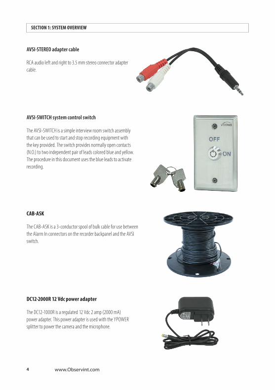
AVSI-STEREO adapter cable
RCA audio left and right to 3.5 mm stereo connector adapter cable.
AVSI-SWITCH system control switch
The AVSI-SWITCH is a simple interview room switch assembly that can be used to start and stop recording equipment with the key provided. The switch provides normally open contacts (N.O.) to two independent pair of leads colored blue and yellow. The procedure in this document uses the blue leads to activate recording.
CAB-ASK
The CAB-ASK is a 3-conductor spool of bulk cable for use between the Alarm In connectors on the recorder backpanel and the AVSI switch.
DC12-2000R 12 Vdc power adapter
The DC12-1000R is a regulated 12 Vdc 2 amp (2000 mA) power adapter. This power adapter is used with the YPOWER splitter to power the camera and the microphone.
5AVSI-12 Interview Room System Setup and User Guide
SECTION 1: SYSTEM OVERVIEW
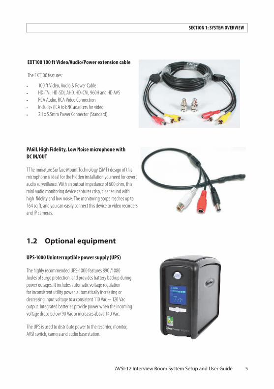
EXT100 100 ft Video/Audio/Power extension cable
The EXT100 features:
• 100 ft Video, Audio & Power Cable• HD-TVI, HD-SDI, AHD, HD-CVI, 960H and HD AVS• RCA Audio, RCA Video Connection• Includes RCA to BNC adapters for video • 2.1 x 5.5mm Power Connector (Standard)
PA6IL High Fidelity, Low Noise microphone with DC IN/OUT
TThe miniature Surface Mount Technology (SMT) design of this microphone is ideal for the hidden installation you need for covert audio surveillance. With an output impedance of 600 ohm, this mini audio monitoring device captures crisp, clear sound with high-fidelity and low noise. The monitoring scope reaches up to 164 sq ft, and you can easily connect this device to video recorders and IP cameras.
1.2 Optional equipment
UPS-1000 Uninterruptible power supply (UPS)
The highly recommended UPS-1000 features 890 /1080 Joules of surge protection, and provides battery backup during power outages. It includes automatic voltage regulation for inconsistent utility power, automatically increasing or decreasing input voltage to a consistent 110 Vac ~ 120 Vac output. Integrated batteries provide power when the incoming voltage drops below 90 Vac or increases above 140 Vac.
The UPS is used to distribute power to the recorder, monitor, AVSI switch, camera and audio base station.
6 www.Observint.com
SECTION 2: GETTING STARTED
SECTION 2 Getting Started
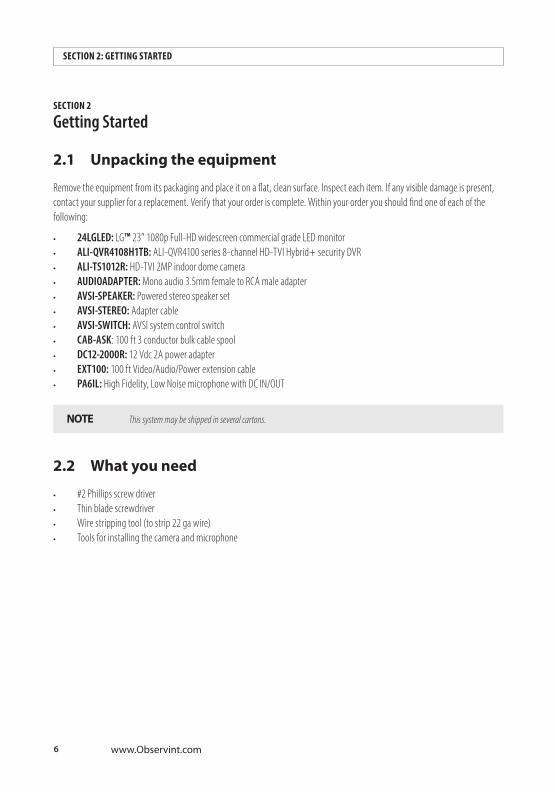
2.1 Unpacking the equipment
Remove the equipment from its packaging and place it on a flat, clean surface. Inspect each item. If any visible damage is present, contact your supplier for a replacement. Verify that your order is complete. Within your order you should find one of each of the following:
• 24LGLED: LG™ 23” 1080p Full-HD widescreen commercial grade LED monitor• ALI-QVR4108H1TB: ALI-QVR4100 series 8-channel HD-TVI Hybrid+ security DVR• ALI-TS1012R: HD-TVI 2MP indoor dome camera• AUDIOADAPTER: Mono audio 3.5mm female to RCA male adapter • AVSI-SPEAKER: Powered stereo speaker set• AVSI-STEREO: Adapter cable • AVSI-SWITCH: AVSI system control switch• CAB-ASK: 100 ft 3 conductor bulk cable spool• DC12-2000R: 12 Vdc 2A power adapter• EXT100: 100 ft Video/Audio/Power extension cable• PA6IL: High Fidelity, Low Noise microphone with DC IN/OUT
NOTE This system may be shipped in several cartons.
2.2 What you need
• #2 Phillips screw driver• Thin blade screwdriver• Wire stripping tool (to strip 22 ga wire)• Tools for installing the camera and microphone

7AVSI-12 Interview Room Systems Setup Guide
SECTION 3: SYSTEM SETUP
SECTION 3 System SetupThe basic Interview Room System system includes an ALI-QVR4108H HD-TVI digital video recorder, an HD-TVI 1080p high definition camera, a hi-gain microphone and speakers.
3.1 Install the recorder hardware
Installing the recorder hardware includes the ALI-QVR4108H HD-TVI recorder and the 24LGLED monitor. A uninterruptible power supply (UPS), not provided, is strongly recommended. When installing this equipment, refer to the ALI-QVR4100H 8/16-Channel AHD, HD-TVI, Analog and IP Camera Recorder Quick Setup Guide and documentation provided with the monitor and other system components for more information.
NOTE Powering the interview room system through a 1000 VA uninterruptible power supply (UPS) is strongly recommended. A UPS is not provided.
1. Place the ALI-QVR4108H unit in a secure location that is within cable distance to the interview room(s) you are monitoring, and in a location that has restricted access. Using the cables provide:
— Cable (EXT100) between the recorder and the camera and microphone is 100 feet. (Longer cables are available. The ALI-TS1012R camera can be extended with a cable length up to 1600 feet.
— Cable (CAB-ASK) between the recorder and the switch is 100 feet.
2. Become familiar with the back panel of the ALI-QVR4108H recorder. The connection points for the devices included in this interview room system are shown in the images below.
12 VDC Plug for power adapter
VIDEO IN CH 1 for camera
AUDIO OUT to speakers
AUDIO IN CH 1 input from microphone
LAN
Ground terminal
Power switch
HDMI/VGA to monitor
Alarm Terminations (See image below)
ALARM IN 1 GROUND (G)
8 www.Observint.com
SECTION 3: SYSTEM SETUP
3. Connect a ground cable to the ground terminal on the back of the recorder. Follow local electrical codes to ensure the recorder is properly grounded.
4. Plug the mouse provided into the USB port on either the front or back of the recorder.
5. Position the monitor in an appropriate viewing location and connect it to the recorder using either the VGA or HDMI interface. A VGA cable is provided with the 24LGLED monitor, but the HDMI interface provides the best performance.
6. If the recorder will be accessible across a local LAN, connect it to a LAN at this time.
NOTE Do not power on the recorder or monitor at this time. The power switch on the recorder is located on the back panel near the 12V power adapter input.
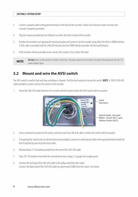
3.2 Mount and wire the AVSI switch
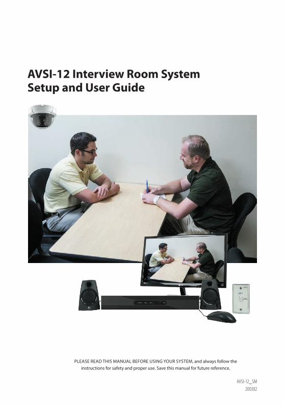
The AVSI switch is used to start and stop recording on channel. Find the best location to locate the switch. NOTE: A 100 ft CAB-ASK cable provided is used to connect the switch to the recorder.
1. Route the CAB-ASK cable between the recorder and the location where the AVSI switch will be mounted.
Switch leads, two pair: White - Green (N.C.) and Yellow-Green (N.O.)
Lead functions
2. Find a convenient location for the switch, and then route the CAB-ASK cable to where the switch will be mounted.
3. If mounting the switch onto an electrical box (not provided), connect an earth ground cable to the ground terminal inside the box if required by your local electrical codes.
4. Remove about 2” of insulating sheath from the end of the CAB-ASK cable.
5. Strip 1/4” of insulation from both the red and black wires using a 22 gauge wire stripping tool.
6. Connect the red lead of the CAB-ASK cable to the yellow lead from the switch. Connect the black lead of the CAB-ASK cable to a green lead (COM) from the switch. See below.

9AVSI-12 Interview Room System Setup and User Guide
SECTION 3: SYSTEM SETUP
NOTE Functions of the wires attached to the switch may change. Always wire the switch so that it functions as a Normally Open (N.O.) switch.
CAB-ASK cable to recorder
White and green leads (unused)
7. Insulate the ends of the white lead and one green lead from the switch using electrical tape. Be certain that they are not electrically connected together.
8. Anchor the CAB-ASK cable to electrical box (if used) or to a wall to prevent it from being pulled away from the switch. Leave a few inches of extra cable between the anchor and the switch for maintenance when needed.
9. Mount the switch plate securely to a wall or electrical box, as determined earlier.
3.3 Connect the CAB-ASK cable to the recorder Alarm In termi-nals
At the back panel of the recorder, do the following:
1. Remove about 2” of insulating sheath from the end of the CAB-ASK cable.
2. Strip 1/4” of insulation from both the red and black wires using a 22 gauge wire stripping tool.
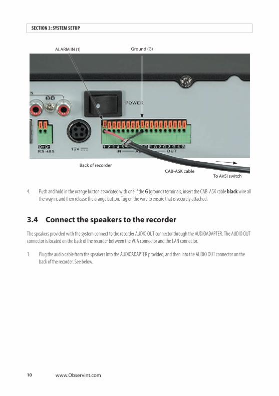
3. At the alarm terminations, push and hold in the orange button associated with the ALARM IN 1 terminal, insert the CAB-ASK cable red wire all the way in, and then release the orange button. Tug on the wire to ensure that is securely attached.
10 www.Observint.com
SECTION 3: SYSTEM SETUP
ALARM IN (1)
CAB-ASK cableTo AVSI switch
Back of recorder
Ground (G)
4. Push and hold in the orange button associated with one if the G (ground) terminals, insert the CAB-ASK cable black wire all the way in, and then release the orange button. Tug on the wire to ensure that is securely attached.
3.4 Connect the speakers to the recorder
The speakers provided with the system connect to the recorder AUDIO OUT connector through the AUDIOADAPTER. The AUDIO OUT connector is located on the back of the recorder between the VGA connector and the LAN connector.
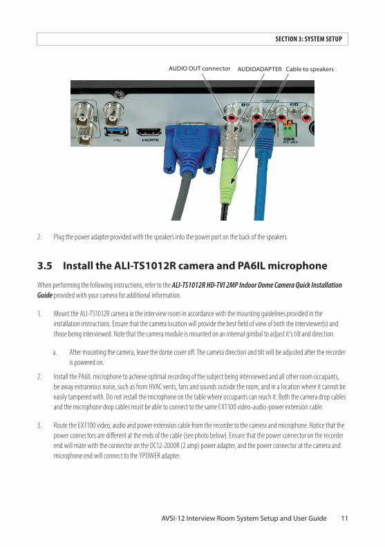
1. Plug the audio cable from the speakers into the AUDIOADAPTER provided, and then into the AUDIO OUT connector on the back of the recorder. See below.
11AVSI-12 Interview Room System Setup and User Guide
SECTION 3: SYSTEM SETUP
AUDIOADAPTER Cable to speakersAUDIO OUT connector
2. Plug the power adapter provided with the speakers into the power port on the back of the speakers.
3.5 Install the ALI-TS1012R camera and PA6IL microphone
When performing the following instructions, refer to the ALI-TS1012R HD-TVI 2MP Indoor Dome Camera Quick Installation Guide provided with your camera for additional information.
1. Mount the ALI-TS1012R camera in the interview room in accordance with the mounting guidelines provided in the installation instructions. Ensure that the camera location will provide the best field of view of both the interviewer(s) and those being interviewed. Note that the camera module is mounted on an internal gimbal to adjust it’s tilt and direction.
a. After mounting the camera, leave the dome cover off. The camera direction and tilt will be adjusted after the recorder is powered on.
2. Install the PA6IL microphone to achieve optimal recording of the subject being interviewed and all other room occupants, be away extraneous noise, such as from HVAC vents, fans and sounds outside the room, and in a location where it cannot be easily tampered with. Do not install the microphone on the table where occupants can reach it. Both the camera drop cables and the microphone drop cables must be able to connect to the same EXT100 video-audio-power extension cable.
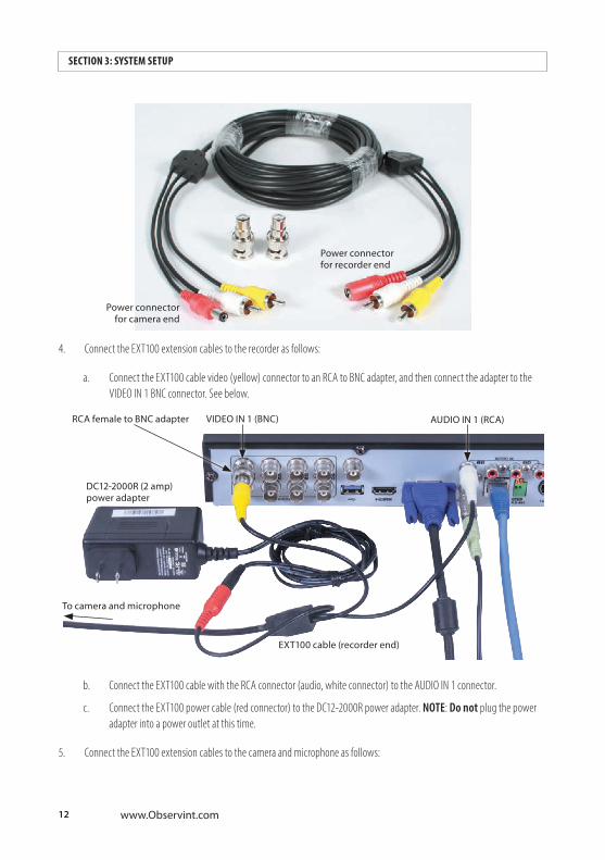
3. Route the EXT100 video, audio and power extension cable from the recorder to the camera and microphone. Notice that the power connectors are different at the ends of the cable (see photo below). Ensure that the power connector on the recorder end will mate with the connector on the DC12-2000R (2 amp) power adapter, and the power connector at the camera and microphone end will connect to the YPOWER adapter.
12 www.Observint.com
SECTION 3: SYSTEM SETUP
Power connector for recorder end
Power connector for camera end
4. Connect the EXT100 extension cables to the recorder as follows:
a. Connect the EXT100 cable video (yellow) connector to an RCA to BNC adapter, and then connect the adapter to the VIDEO IN 1 BNC connector. See below.
DC12-2000R (2 amp) power adapter
EXT100 cable (recorder end)
To camera and microphone
RCA female to BNC adapter VIDEO IN 1 (BNC) AUDIO IN 1 (RCA)
b. Connect the EXT100 cable with the RCA connector (audio, white connector) to the AUDIO IN 1 connector.
c. Connect the EXT100 power cable (red connector) to the DC12-2000R power adapter. NOTE: Do not plug the power adapter into a power outlet at this time.
5. Connect the EXT100 extension cables to the camera and microphone as follows:
13AVSI-12 Interview Room System Setup and User Guide
SECTION 3: SYSTEM SETUP
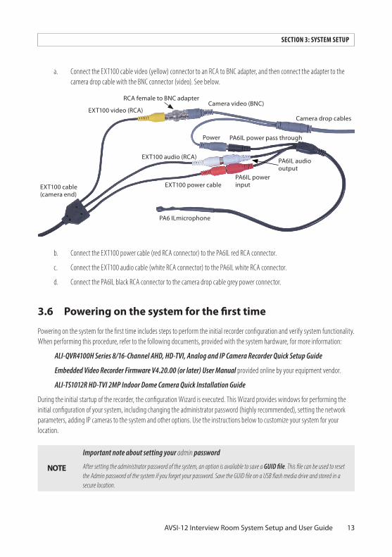
a. Connect the EXT100 cable video (yellow) connector to an RCA to BNC adapter, and then connect the adapter to the camera drop cable with the BNC connector (video). See below.
EXT100 cable (camera end)
EXT100 power cablePA6IL power input
PA6IL audio output
PA6IL power pass through
EXT100 audio (RCA)
Camera drop cables
Camera video (BNC)EXT100 video (RCA)
PA6 ILmicrophone
Power
RCA female to BNC adapter
b. Connect the EXT100 power cable (red RCA connector) to the PA6IL red RCA connector.
c. Connect the EXT100 audio cable (white RCA connector) to the PA6IL white RCA connector.
d. Connect the PA6IL black RCA connector to the camera drop cable grey power connector.
3.6 Powering on the system for the first time
Powering on the system for the first time includes steps to perform the initial recorder configuration and verify system functionality. When performing this procedure, refer to the following documents, provided with the system hardware, for more information:
ALI-QVR4100H Series 8/16-Channel AHD, HD-TVI, Analog and IP Camera Recorder Quick Setup Guide
Embedded Video Recorder Firmware V4.20.00 (or later) User Manual provided online by your equipment vendor.
ALI-TS1012R HD-TVI 2MP Indoor Dome Camera Quick Installation Guide
During the initial startup of the recorder, the configuration Wizard is executed. This Wizard provides windows for performing the initial configuration of your system, including changing the administrator password (highly recommended), setting the network parameters, adding IP cameras to the system and other options. Use the instructions below to customize your system for your location.
NOTE
Important note about setting your admin password
After setting the administrator password of the system, an option is available to save a GUID file. This file can be used to reset the Admin password of the system if you forget your password. Save the GUID file on a USB flash media drive and stored in a secure location.
14 www.Observint.com
SECTION 3: SYSTEM SETUP
14
When the recorder is first powered on, it is in an “Inactive” state, which means that it does not have an admin user password for the recorder, and it is not configured to record video or log system status messages. The initial configuration screen enables you to activate the recorder.
After activating the recorder and configuring its security options, a configuration Wizard will open. The Wizard helps you to easily configure the recorder for its basic settings, including date and time, network configuration, network cameras, HDD initialization, etc.
NOTE After completing system setup with the Wizard, the recorder will record on Channel 1 when the AVSI switch is ON, and record on other all other channels with cameras when motion is detected on that channel.
3.7 System activation
1. Power on the recorder. Normally, an Alibi logo splash screen appears within 2 minutes.
2. Power on the camera.
3. The following screen is used to activate the recorder.
15AVSI-12 Interview Room System Setup and User Guide
SECTION 3: SYSTEM SETUP
15
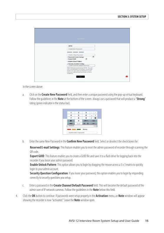
In the screen above:
a. Click on the Create New Password field, and then enter a unique password using the pop-up virtual keyboard. Follow the guidelines in the Note at the bottom of the screen. Always use a password that will produce a “Strong” rating (green indicator in the status bar).
b. Enter the same New Password in the Confirm New Password field. Select or deselect the check boxes for:
Reserved E-mail Settings: This feature enables you to reset the admin password of recorder through scanning the QR code. Export GUID: This feature enables you to create a GUID file and save it to a flash drive for logging back into the recorder if you loose your admin password. Enable Unlock Pattern: This option allows you to login by dragging the mouse across a 3 x 3 matrix to quickly login to your admin account. Security Question Configuration: If you loose your password, this option enables you to login by responding correctly to security questions you setup.
c. Enter a password in the Create Channel Default Password field. This will become the default password of the admin user of IP network cameras. Follow the guidelines in the Note below this field.
4. Click the OK button to continue. If passwords were setup properly in the Activation menu, an Note window will appear showing the recorder is now “activated.” Leave the Note window open.

16 www.Observint.com
SECTION 3: SYSTEM SETUP
16
5. If you selected options for Reserve E-mail Setting, enter a valid email address in the pop-up window.
a. Click OK. Your email address will be verified.
b. In the Note window, click OK to continue.
6. If you selected the option in the Activation screen to Export GUID, use the instructions in this step to use this feature.
a. Plug a flash drive into an unused USB port on the recorder, and then click the Refresh icon (see below).
Refresh icon
b. In the GUID Import/Export window, open the Device Name drop down list and then select the device where you want to save the GUID file. If a list of directories appear, click on the directory you prefer (in the window shown above, the first directory was selected). Some options will appear at the bottom of the screen to add a New Folder or Erase files.
17AVSI-12 Interview Room System Setup and User Guide
SECTION 3: SYSTEM SETUP
17
c. Click Export, and then allow the export operation to complete.
d. After the export operation completes, remove the flash drive from the recorder and store it in a secure location.
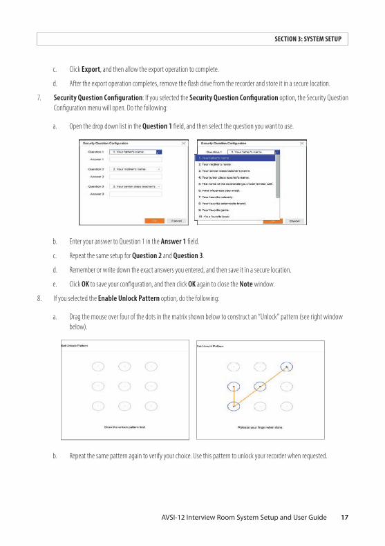
7. Security Question Configuration: If you selected the Security Question Configuration option, the Security Question Configuration menu will open. Do the following:
a. Open the drop down list in the Question 1 field, and then select the question you want to use.
b. Enter your answer to Question 1 in the Answer 1 field.
c. Repeat the same setup for Question 2 and Question 3.
d. Remember or write down the exact answers you entered, and then save it in a secure location.
e. Click OK to save your configuration, and then click OK again to close the Note window.
8. If you selected the Enable Unlock Pattern option, do the following:
a. Drag the mouse over four of the dots in the matrix shown below to construct an “Unlock” pattern (see right window below).
b. Repeat the same pattern again to verify your choice. Use this pattern to unlock your recorder when requested.
18 www.Observint.com
SECTION 3: SYSTEM SETUP
18
3.8 Using the setup Wizard
During startup of a new recorder, the setup Wizard opens by default. Use the Wizard to select the essential configuration settings of your recorder. You can disable the automatic startup of this feature in the Configuration menu. See the Menu | Configuration | General menu for more information.
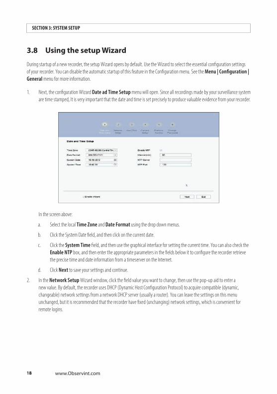
1. Next, the configuration Wizard Date ad Time Setup menu will open. Since all recordings made by your surveillance system are time stamped, It is very important that the date and time is set precisely to produce valuable evidence from your recorder.
In the screen above:
a. Select the local Time Zone and Date Format using the drop down menus.
b. Click the System Date field, and then click on the current date.
c. Click the System Time field, and then use the graphical interface for setting the current time. You can also check the Enable NTP box, and then enter the appropriate parameters in the fields below it to configure the recorder retrieve the precise time and date information from a timeserver on the Internet.
d. Click Next to save your settings and continue.
2. In the Network Setup Wizard window, click the field value you want to change, then use the pop-up aid to enter a new value. By default, the recorder uses DHCP (Dynamic Host Configuration Protocol) to acquire compatible (dynamic, changeable) network settings from a network DHCP server (usually a router). You can leave the settings on this menu unchanged, but it is recommended that the recorder have fixed (unchanging) network settings, which is convenient for remote logins.
19AVSI-12 Interview Room System Setup and User Guide
SECTION 3: SYSTEM SETUP
19
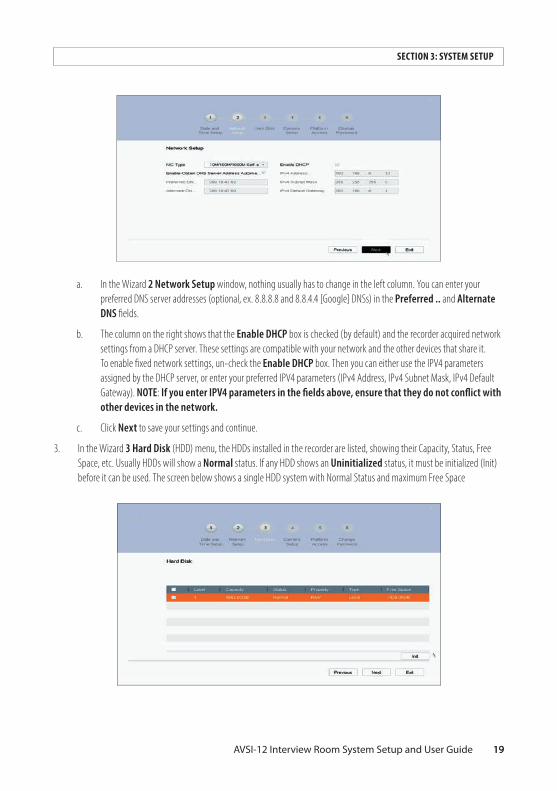
a. In the Wizard 2 Network Setup window, nothing usually has to change in the left column. You can enter your preferred DNS server addresses (optional, ex. 8.8.8.8 and 8.8.4.4 [Google] DNSs) in the Preferred . . and Alternate DNS fields.
b. The column on the right shows that the Enable DHCP box is checked (by default) and the recorder acquired network settings from a DHCP server. These settings are compatible with your network and the other devices that share it. To enable fixed network settings, un-check the Enable DHCP box. Then you can either use the IPV4 parameters assigned by the DHCP server, or enter your preferred IPV4 parameters (IPv4 Address, IPv4 Subnet Mask, IPv4 Default Gateway). NOTE: If you enter IPV4 parameters in the fields above, ensure that they do not conflict with other devices in the network .
c. Click Next to save your settings and continue.
3. In the Wizard 3 Hard Disk (HDD) menu, the HDDs installed in the recorder are listed, showing their Capacity, Status, Free Space, etc. Usually HDDs will show a Normal status. If any HDD shows an Uninitialized status, it must be initialized (Init) before it can be used. The screen below shows a single HDD system with Normal Status and maximum Free Space

20 www.Observint.com
SECTION 3: SYSTEM SETUP
20
If any HDD listed shows a status other than Normal (such as, Uninitialized), it must be initialized (Init), which formats it to a usable condition. To Initialize an HDD:
CAUTION HDD initialization erases all data on the disk.
a. Check the select box for the HDD(s) you want to initialize.
b. Click the Init button.
c. Wait for the operation to complete (this could take several minutes), and then click Next to continue.
4. In the Wizard 4 Camera Setup menu, you can select add cameras discovered on the local network to your surveillance system. Most recorders have a limit of how many network cameras can be added to the system. You can also use the recorder to Activate cameras on the network. A camera must be activated before it can be added.
To activate a IP network camera with the recorder:
a. Click the Search button to discover the cameras attached to your local network (network to which the recorder is attached).
b. Scroll through the list of cameras found on the local network, and then check the select box for the cameras you want to activate.
c. Click the Activate button. Follow the on-screen instructions to enter a camera admin user default password and complete the activation.
To add a network camera to the recorder:
a. Click the Search button to discover the cameras attached to your local network (network to which the recorder is attached).

21AVSI-12 Interview Room System Setup and User Guide
SECTION 3: SYSTEM SETUP
21
b. Scroll through the list of cameras found on the local network, and then check the select box for the cameras you want to add. See above.
c. Click the Add button. Allow the operation to complete before continuing.
5. In the Wizard 5 Platform Access menu, you can setup Platform Access, enable DDNS, and/or configure Stream Encryption.
Platform Access is used with the Alibi Witness 2 smartphone app to simplify access and control how others can access the system. To enable Platform Access for your recorder, check the Enable box (see the screen above). Then follow the on-screen instructions for activating this service. Refer to the Alibi Witness 2 .0 user documentation for instructions on using the platform access feature. Refer to the ALIBI™ Witness 2 .0 v3 User Guide available from your vendor for more information.
Enable DDNS enables DDNS (Dynamic Domain Name System) access to the recorder. This feature simplifies access to the recorder, especially when the IP address of the recorder may change. For more information on setting up a DDNS service for the recorder, refer to firmware user manual for the recorder. You can download the firmware user manual for your recorder from AlibiSecurity.com/resources. Refer to the for more information.
Enable Stream Encryption. Stream encryption enables to encrypt the streams for live view, playback, download, backup, etc. To use stream encryption:
a. Check the Enable Stream Encryption select box.
b. Create an encryption password.
NOTE The stream encryption password is synchronized with the Alibi Connect service verification code. After enabling the encryption code, the Alibi Connect stream will be forcedly encrypted. Make sure your Alibi Connect service supports stream encryption.
6. In the Wizard 6 Change Password and Ports menu, you can modify your admin password and change the Server, HTTP and RSTP port numbers.

22 www.Observint.com
SECTION 3: SYSTEM SETUP
NOTE Changing the port numbers on the screen above can provide better security for you system, but can complicate the ability to access the recorder and download data from it. Consult with your Alibi Support organization for more information.
a. To change the password, check the New Admin Password box, and then follow the on screen instructions.
b. To change the port numbers, enter the new port numbers in the field provided.
c. To save your settings and exit the configuration Wizard, click Finish. Click Previous to return to an another Wizard menu. After clicking Finish, the Live View window will open.
Menu icon
23AVSI-12 Interview Room System Setup and User Guide
SECTION 3: SYSTEM SETUP
7. While viewing video from each cameras in the Live View display, adjust the direction of the camera(s) to aim it at its surveillance target. Follow the manufacturer’s recommended procedures for aiming the cameras.
3.9 Opening the Menu system
After the initial setup of your recorder using the Wizard, the Menus interface enables you to refine your configuration settings and expand the functionality of the system.
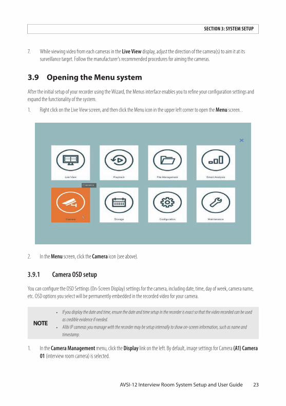
1. Right click on the Live View screen, and then click the Menu icon in the upper left corner to open the Menu screen. .
2. In the Menu screen, click the Camera icon (see above).
3 .9 .1 Camera OSD setup
You can configure the OSD Settings (On-Screen Display) settings for the camera, including date, time, day of week, camera name, etc. OSD options you select will be permanently embedded in the recorded video for your camera.
NOTE
• If you display the date and time, ensure the date and time setup in the recorder is exact so that the video recorded can be used as credible evidence if needed.
• Alibi IP cameras you manage with the recorder may be setup internally to show on-screen information, such as name and timestamp.
1. In the Camera Management menu, click the Display link on the left. By default, image settings for Camera (A1) Camera 01 (interview room camera) is selected.

24 www.Observint.com
SECTION 3: SYSTEM SETUP
2. In the Display menu, click the expand-more icon on the OSD Settings line to open the OSD menu.
expand-more icon
3. Open the Camera drop-down list and select the camera you want to configure. In the screen below, camera [A1] Camera 01 is selected.
4. You can enter a new name for the camera bu clicking the Camera Name field. In this example, the camera is renamed: Interview Room 1.
5. In the OSD menu, check the select boxes for the information you want to appear on the screen, such as camera name, date and/or week. Information you selected will appear in the text boxes shown in the video window.
a. If you selected Display Name, enter the name of the camera in the Camera Name field near the top of the window.

25AVSI-12 Interview Room System Setup and User Guide
SECTION 3: SYSTEM SETUP
b. For other items you selected, open the drop down lists for the Date/Time Format, Display Mode and OSD Font as needed and select the best choice for your camera.
c. Drag the text boxes to the best locations in the camera field of view.
6. Click Apply to save your settings.
3 .9 .2 Camera Image Settings
1. In the Display menu, click the expand-more icon on the Image Settings line.
2. In the Camera field drop down list, select the camera you want to configure. In the example above, [A1] Camera 01 is selected.
3. Click the expand icon for Image Settings.
4. Open the Mode drop-down list, and then select the option that best applies to the where the camera is installed. If you are configuring an IP camera, the only option is Custom.
5. Adjust the sliders for the Brightness, Contrast, Saturation, Hue, Sharpness and Denoising to produce the best image. If you are configuring an IP camera, options for Sharpness and Denoising are not available.
6. If you are configuring an IP camera, open the drop down lists for Enable Rotation, Mirror Mode and Scene Mode, then select best option for each for this camera installation.
7. Click Apply to save your settings for this camera.

26 www.Observint.com
SECTION 3: SYSTEM SETUP
3 .9 .3 Camera Video Parameters
Use the Video Parameters Main Stream and Sub-Stream menus to verify that both video and audio from the interview room camera will be recorded. These menus can also be used for adjusting video and audio parameters. Parameter options depend on the capability of the camera. These menus, with the network bandwidth calculator available on AlibiSecurity.com/resources, can help you get the best performance from your security system network.
Main Stream Parameters
In the Main Stream Parameters menu, ensure that both the Main Stream (Continuous) and Main Stream (Event) parameters are configured to stream Video & Audio. Other video parameters are normally set to provide adquate camera performance. you can adjust camera parameters for both main stream Continuous recording and main stream Event recording. Refer to the Specifications for your camera(s) to see what options for main stream performance are available.
1. In the Camera menu, click on Video Parameters, and then click on Main Stream.
2. In the Camera field drop down list, select the Interview Room camera (in this example, [A1] Interview Room 1).
3. For both the Main Stream (Continuous) and Main Stream (Event) parameters:
a. Ensure that the stream type is set to Video & Audio.
b. Open the Frame Rate drop down list and select Full Frame.

27AVSI-12 Interview Room System Setup and User Guide
SECTION 3: SYSTEM SETUP
c. Adjust other parameters as needed for the camera performance you require.
4. Click Apply to save your settings for this camera.
Sub-Streams
In the Sub-Stream menu, ensure that the Stream Type option is configured to stream Video and Audio. The sub-stream is normally used for cloud storage and remote access to the recorder.
28 www.Observint.com
SECTION 3: SYSTEM SETUP
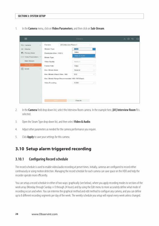
1. In the Camera menu, click on Video Parameters, and then click on Sub-Stream.
2. In the Camera field drop down list, select the Interview Room camera. In the example here, [A1] Interview Room 1 is selected.
3. Open the Steam Type drop down list, and then select Video & Audio.
4. Adjust other parameters as needed for the camera performance you require.
5. Click Apply to save your settings for this camera.
3.10 Setup alarm triggered recording
3 .10 .1 Configuring Record schedule
The record schedule is used to enable video/audio recording at preset times. Initially, cameras are configured to record either continuously or using motion detection. Managing the record schedule for each camera can save space on the HDD and help the recorder operate more efficiently.
You can setup a record schedule in either of two ways: graphically (see below), where you apply recording modes to sections of the week array (Monday through Sunday × 0 through 24 hours) and by using the Edit menu to more accurately define what mode of recording occurs and when. You can intermix the graphical method and edit method to configure any camera, and you can define up to 8 different recording segments per day of the week. The weekly schedule you setup will repeat every week unless changed.

29AVSI-12 Interview Room System Setup and User Guide
SECTION 3: SYSTEM SETUP
To configure the camera on video in [A1] Channel 01 to be recorded when the AVSI switch is ON, the camera ({A1} Camera 01) is selected and the schedule is enabled, and the schedule is changed to allow Alarm recording at any time.
NOTE You can also set up a special recording schedule for Holidays and configure up to 8 different recording schedules for holidays.
1. Open the Record Schedule menu. Go to Menu | Storage | Schedule | Record. By default, the schedule shown below is setup to record continuously only throughout the week.
2. To configure the Record schedule:
a. Open the Camera No, drop-down list to select the camera you want to configure. In this example, the camera installed in the interview room, attached to [A1] Interview Room 1, is selected.
b. Check the Enable Schedule box.
c. Click the Advanced button.
In the Advanced Parameters menu:
30 www.Observint.com
SECTION 3: SYSTEM SETUP
i. Check the Record Audio select box.
ii. Set the Pre-Record and Post-Record times using the drop down lists. These parameters set the number of seconds of video before and after an event occurs what will be saved in storage.
iii. Open the Steam Type drop down list to select the video stream you want to record. You can select Dual, but that requires more bandwidth and storage space. Main Stream has the highest resolution.
iv. Set the Video/Picture Expired Time (day) parameter as needed. This parameter sets the expired time for a recorded file to be kept in the HDD. When the deadline is reached, the file will be deleted. If you set the expired time to “0,” the file will not be deleted. The retention time for a file is determined in consideration of the capacity of the HDD.
v. Click OK to save your settings.
Setting the Recording Schedule graphically
To graphically configure the recording schedule, simply click the recording mode you want to apply, and then drag a rectangle across the areas of the array you want to change. Each segment of the array represents 30 minutes. To graphically change the recording schedule for Alarm recording (type of event created when the AVSI switch is ON):
1. Open the Camera No . drop down list and then select the video in channel the camera in interview room is connected to ([A1] Interview Room 1).
2. Ensure the Enable Schedule select box is checked.
3. Click on the Alarm recording mode buttons above the array to select the mode you want to use. Mode buttons include: Continuous: scheduled recording. Event: recording triggered by all event triggered alarm. Motion: recording triggered by motion detection. Alarm: recording triggered by alarm. M/A: recording triggered by either motion detection or alarm. M&A: recording triggered by motion detection and alarm. None (no mode)

31AVSI-12 Interview Room System Setup and User Guide
SECTION 3: SYSTEM SETUP
Alarm recording mode selected
Area graphically selected
Camera [A1] Interview Room 1 selected Schedule enable
4. Use the mouse to drag a rectangle across the area of the schedule array you want to change (see above). A red rectangle will show the area you selected. In this example, the entire week was selected. When you release the mouse button, the recording mode in that area will change to the mode you selected. See below.
5. Click Apply to save your settings.

32 www.Observint.com
SECTION 3: SYSTEM SETUP
3 .10 .2 Configure Alarm IN 1 and recording trigger
Use this procedure to setup the Alarm 1 IN circuitry to trigger video and audio recording on [A1]Channel 01 when the AVSI switch is ON.
1. Open the Alarm IN menu. Go to Menu | Camera | Event | Normal Event .
2. For Alarm Input No. Local<- 1, click the checkbox in the Edit column. See above.
3. In the Edit popup window, enter an Alarm Name for the alarm you are configuring. In the example below, Interview room 1 was entered.

33AVSI-12 Interview Room System Setup and User Guide
SECTION 3: SYSTEM SETUP
4. Open the Type drop down list, and then select N .O . (Normally Open) if not already selected.
5. Click the Input radial button. An Arming Schedule will appear. By default this schedule enables the Local<- 1 alarm continuously. You can modify this schedule as done with the Record schedule (see above), if needed.
Input radial button
6. Click Apply to save your settings.
7. Click the Linkage Action tab.
34 www.Observint.com
SECTION 3: SYSTEM SETUP
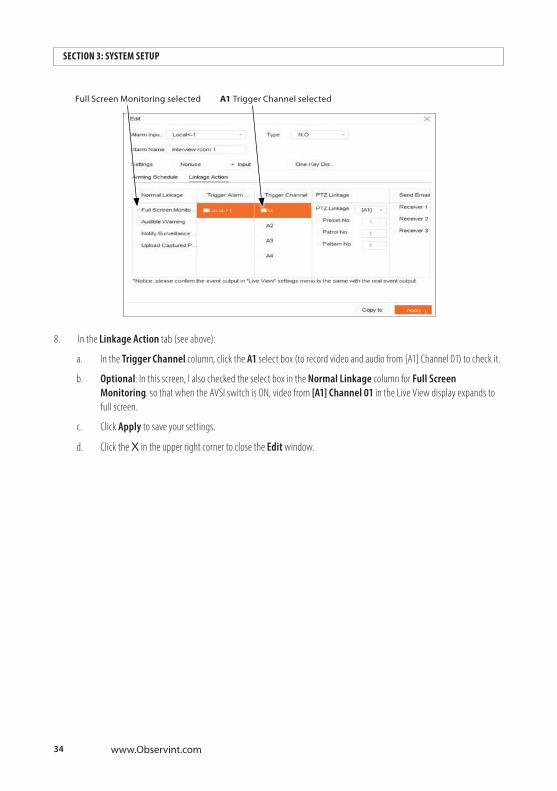
Full Screen Monitoring selected A1 Trigger Channel selected
8. In the Linkage Action tab (see above):
a. In the Trigger Channel column, click the A1 select box (to record video and audio from [A1] Channel 01) to check it.
b. Optional: In this screen, I also checked the select box in the Normal Linkage column for Full Screen Monitoring. so that when the AVSI switch is ON, video from [A1] Channel 01 in the Live View display expands to full screen.
c. Click Apply to save your settings.
d. Click the X in the upper right corner to close the Edit window.
35AVSI-12 Interview Room System Setup and User Guide
SECTION 4: TEST/USE THE INTERVIEW ROOM SYSTEM
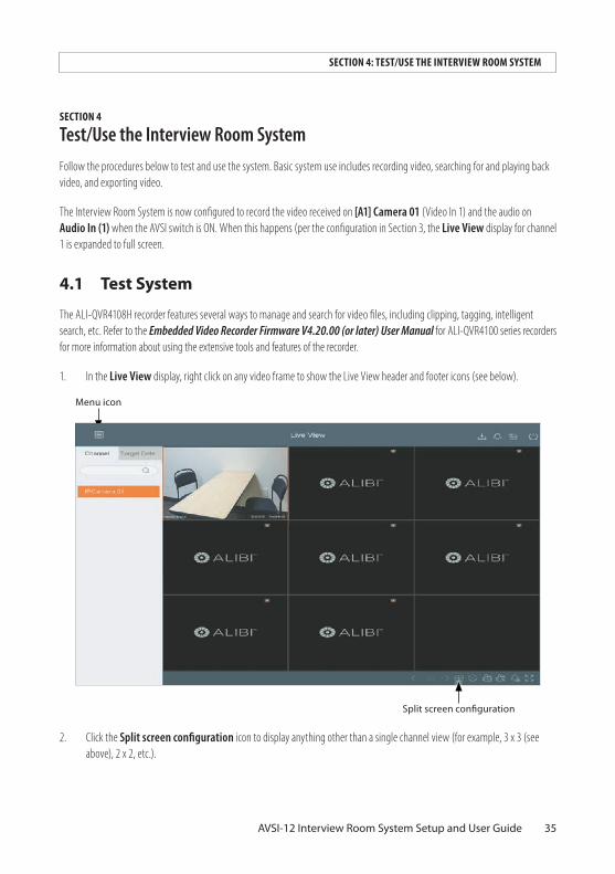
SECTION 4 Test/Use the Interview Room SystemFollow the procedures below to test and use the system. Basic system use includes recording video, searching for and playing back video, and exporting video.
The Interview Room System is now configured to record the video received on [A1] Camera 01 (Video In 1) and the audio on Audio In (1) when the AVSI switch is ON. When this happens (per the configuration in Section 3, the Live View display for channel 1 is expanded to full screen.
4.1 Test System
The ALI-QVR4108H recorder features several ways to manage and search for video files, including clipping, tagging, intelligent search, etc. Refer to the Embedded Video Recorder Firmware V4.20.00 (or later) User Manual for ALI-QVR4100 series recorders for more information about using the extensive tools and features of the recorder.
1. In the Live View display, right click on any video frame to show the Live View header and footer icons (see below).
Menu icon
Split screen configuration
2. Click the Split screen configuration icon to display anything other than a single channel view (for example, 3 x 3 (see above), 2 x 2, etc.).

36 www.Observint.com
SECTION 4: TEST/USE THE INTERVIEW ROOM SYSTEM
3. Ensure that the speakers are powered on.
4. Set the AVSI switch to ON. The camera image of Camera 01 should expand to full screen and a red status icon (recording in progress) should appear in the upper right corner of the screen.
5. Record the time when the AVSI switch was turned on. This information will be used later during playback.
Red recording in progress icon
6. Verify that the red Recording in Progress icon appears on the video image (see above).
7. While recording, move throughout the field of view, and talk normally. Verify that audio can be heard through the speakers.
8. Set the AVSI switch to OFF. The Live View screen should return to Multi-screen mode, and the Recording in progress icon in the upper right corner of Camera 01 video should disappear.
4.2 Playback recorded video
The ALI-QVR4108H recorder features several ways search for, playback and manage video files, including clipping, tagging, intelligent search, etc. Refer to the Embedded Video Recorder Firmware V4.20.00 (or later) User Manual for ALI-QVR4100 series recorders for more information about using the extensive tools and features of the recorder.
To playback a recording using the most common method, do the following:
1. Right click anywhere on the Live View screen, and then click Menu in the popup list. NOTE: An Admin login window may appear. If it does, enter your Admin password in the window, and then click OK to continue.
37AVSI-12 Interview Room System Setup and User Guide
SECTION 4: TEST/USE THE INTERVIEW ROOM SYSTEM
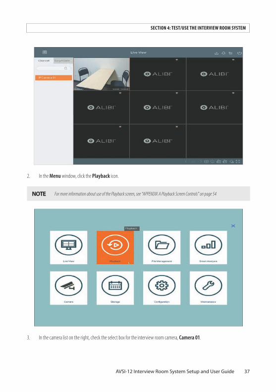
2. In the Menu window, click the Playback icon.
NOTE For more information about use of the Playback screen, see “APPENDIX A Playback Screen Controls” on page 54
3. In the camera list on the right, check the select box for the interview room camera, Camera 01.

38 www.Observint.com
SECTION 4: TEST/USE THE INTERVIEW ROOM SYSTEM
Interview room camera
Day recording was made Marks on timeline indicate recordings
4. In the calendar below the camera list, click on the date of the recording you want to playback. In the example above, February 20, 2020 was selected. After selecting the date, the timeline at the bottom of the screen will show times when recordings for the camera were made, and color-code the mark to indicate if it was a Normal (blue) or Event (red) recording. Recordings initiated by the AVSI switch (Alarm IN) will always be Event recordings. You can click the icon to the right of the timeline to expand or contract the timeline.
5. After expanding the timeline and click the Play ( u ) in playback controls, the playback screen will show the video being recorder earlier. You can stop playing the video by clicking either the Pause ( II ) icon or Stop ( n ) icon.

39AVSI-12 Interview Room System Setup and User Guide
SECTION 4: TEST/USE THE INTERVIEW ROOM SYSTEM
Timestamp of video frame shown here
6. During playback of the video, verify that you can hear sound from the recording, and the video started and stopped at the time when the AVSI switch turned ON and OFF.
4.3 Export recorded video
In this example, the video recorded from testing the system will be exported to a USB flash drive.
1. Insert a USB flash drive into an USB port on the recorder.
2. In the playback window:
40 www.Observint.com
SECTION 4: TEST/USE THE INTERVIEW ROOM SYSTEM
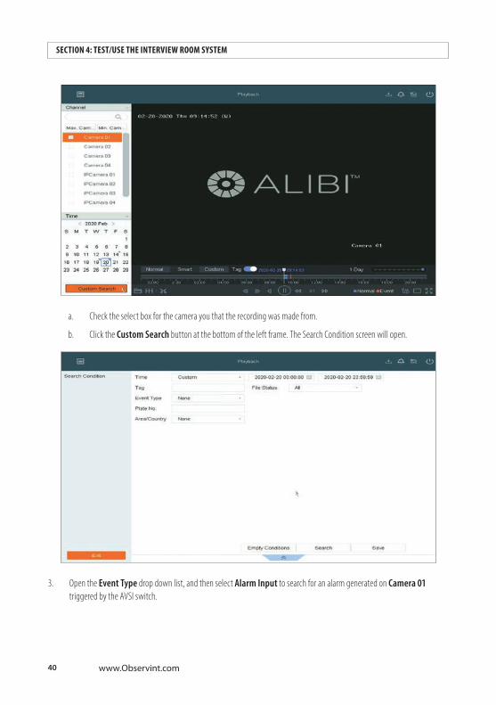
a. Check the select box for the camera you that the recording was made from.
b. Click the Custom Search button at the bottom of the left frame. The Search Condition screen will open.
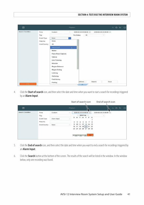
3. Open the Event Type drop down list, and then select Alarm Input to search for an alarm generated on Camera 01 triggered by the AVSI switch.
41AVSI-12 Interview Room System Setup and User Guide
SECTION 4: TEST/USE THE INTERVIEW ROOM SYSTEM
4. Click the Start of search icon, and then select the date and time when you want to start a search for recordings triggered by an Alarm Input.
Start of search icon End of search icon
5. Click the End of search icon, and then select the date and time when you want to end a search for recordings triggered by an Alarm Input.
6. Click the Search button at the bottom of the screen. The results of the search will be listed in the window. In the window below, only one recording was found.

42 www.Observint.com
SECTION 4: TEST/USE THE INTERVIEW ROOM SYSTEM
7. You can click the icon in the View column to play the video.
8. In the Playback screen, click Custom Search again to return to the Search results screen.

43AVSI-12 Interview Room System Setup and User Guide
SECTION 4: TEST/USE THE INTERVIEW ROOM SYSTEM
9. To export the video (see screen above):
a. Click on the entry in the list you want to export. It will be highlighted as shown above.
b. Click the All or Video button in the upper right corner of the screen.
c. Click the Export button.
d. In the Export popup window, select Video and log (normal), or Player. Player is used for playing an optional proprietary video file format exported by the recorder. In this example, I selected Video and log.
e. Click OK.
Refresh button
f. In the Path Settings window, click the Refresh button (see above), and then double click on the directory in the USB drive where you want to save the recording.
44 www.Observint.com
SECTION 4: TEST/USE THE INTERVIEW ROOM SYSTEM
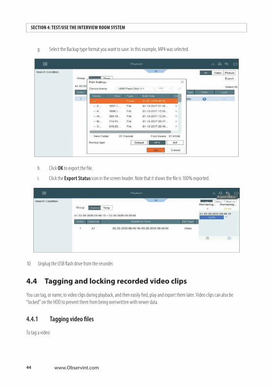
g. Select the Backup type format you want to save. In this example, MP4 was selected.
h. Click OK to export the file.
i. Click the Export Status icon in the screen header. Note that it shows the file is 100% exported.
10. Unplug the USB flash drive from the recorder.
4.4 Tagging and locking recorded video clips
You can tag, or name, to video clips during playback, and then easily find, play and export them later. Video clips can also be “locked” on the HDD to prevent them from being overwritten with newer data.
4 .4 .1 Tagging video files
To tag a video:

45AVSI-12 Interview Room System Setup and User Guide
SECTION 4: TEST/USE THE INTERVIEW ROOM SYSTEM
1. While the video is being played back, hover the mouse pointer over the video frame. A group of pop-up icons will appear at the bottom of the window.
Add Tag icon.
2. Click the Add Tag icon. See above.
3. In the window that opens, enter a Tag Name using the virtual keyboard.
46 www.Observint.com
SECTION 4: TEST/USE THE INTERVIEW ROOM SYSTEM
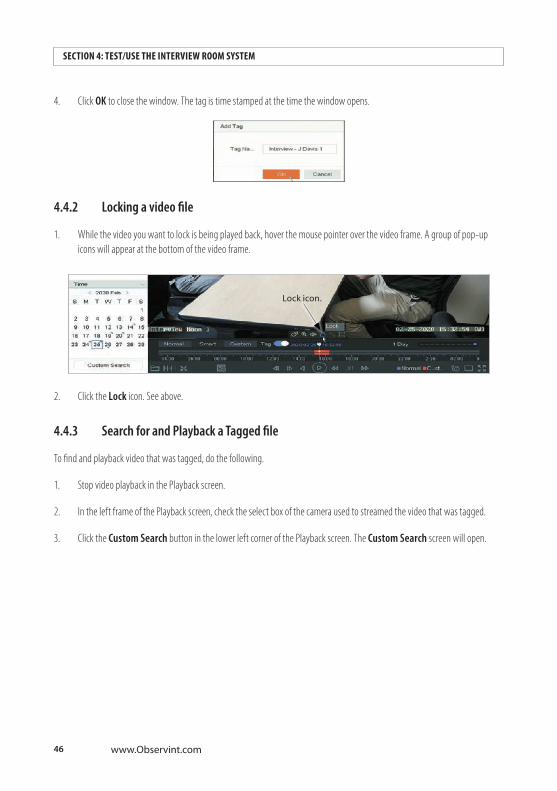
4. Click OK to close the window. The tag is time stamped at the time the window opens.
4 .4 .2 Locking a video file
1. While the video you want to lock is being played back, hover the mouse pointer over the video frame. A group of pop-up icons will appear at the bottom of the video frame.
Lock icon.
2. Click the Lock icon. See above.
4 .4 .3 Search for and Playback a Tagged file
To find and playback video that was tagged, do the following.
1. Stop video playback in the Playback screen.
2. In the left frame of the Playback screen, check the select box of the camera used to streamed the video that was tagged.
3. Click the Custom Search button in the lower left corner of the Playback screen. The Custom Search screen will open.

47AVSI-12 Interview Room System Setup and User Guide
SECTION 4: TEST/USE THE INTERVIEW ROOM SYSTEM
4. To find the tag created earlier in these procedures (“Interview - J Davis”), click inside the tag field, and then use the virtual keyboard to enter the tag name. Here, we just entered part of the tag name, “J Davis”, to find the tag. See below.
Start of search icon End of search icon
5. Click the Calendar icons for the Start of search and End of search to set the time range to search.
6. Click the Search button at the bottom of the screen. In this example, one result was found for the camera selected.
48 www.Observint.com
SECTION 4: TEST/USE THE INTERVIEW ROOM SYSTEM
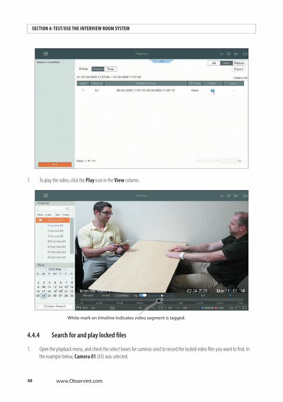
7. To play the video, click the Play icon in the View column.
White mark on timeline indicates video segment is tagged.
4 .4 .4 Search for and play locked files
1. Open the playback menu, and check the select boxes for cameras used to record the locked video files you want to find. In the example below, Camera 01 (A1) was selected.

49AVSI-12 Interview Room System Setup and User Guide
SECTION 4: TEST/USE THE INTERVIEW ROOM SYSTEM
2. Click the Custom Search button in the lower left corner of the screen.
3. In the Custom Search window, click the calendar icons to set a date range that includes when the locked files you want were recorded.
Start of search icon End of search icon
4. Open the File Status drop down list, and then select Locked.
5. Click the Search button at the bottom of the screen. A list of video files that match your search criteria will be displayed. The icon in the Lock column below shows the file is locked. Click the Play icon in the View column to watch the video.
50 www.Observint.com
SECTION 4: TEST/USE THE INTERVIEW ROOM SYSTEM
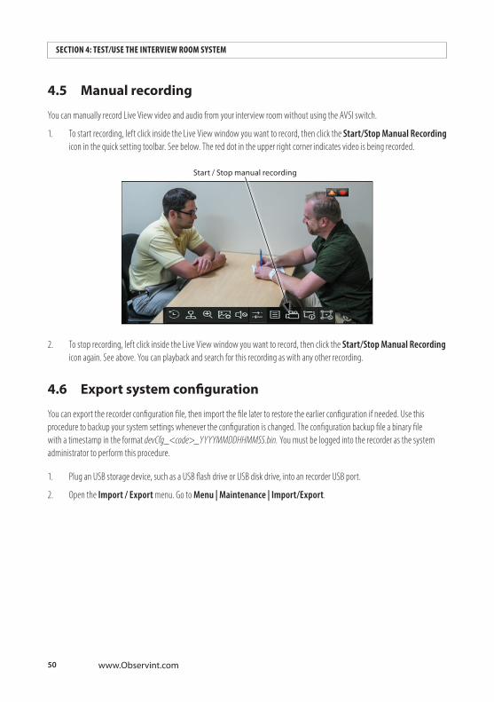
4.5 Manual recording
You can manually record Live View video and audio from your interview room without using the AVSI switch.
1. To start recording, left click inside the Live View window you want to record, then click the Start/Stop Manual Recording icon in the quick setting toolbar. See below. The red dot in the upper right corner indicates video is being recorded.
Start / Stop manual recording
2. To stop recording, left click inside the Live View window you want to record, then click the Start/Stop Manual Recording icon again. See above. You can playback and search for this recording as with any other recording.
4.6 Export system configuration
You can export the recorder configuration file, then import the file later to restore the earlier configuration if needed. Use this procedure to backup your system settings whenever the configuration is changed. The configuration backup file a binary file with a timestamp in the format devCfg_<code>_YYYYMMDDHHMMSS.bin. You must be logged into the recorder as the system administrator to perform this procedure.
1. Plug an USB storage device, such as a USB flash drive or USB disk drive, into an recorder USB port.
2. Open the Import / Export menu. Go to Menu | Maintenance | Import/Export.
51AVSI-12 Interview Room System Setup and User Guide
SECTION 4: TEST/USE THE INTERVIEW ROOM SYSTEM
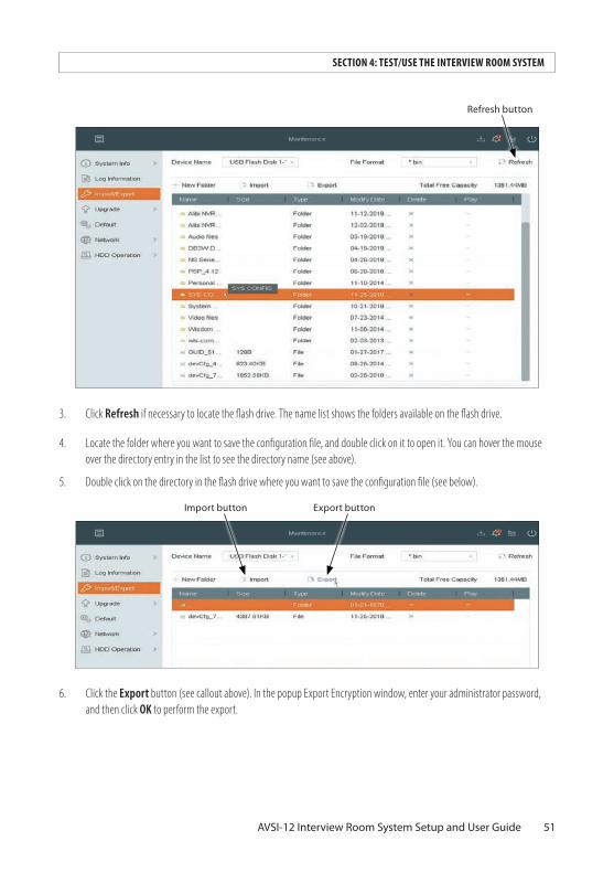
Refresh button
3. Click Refresh if necessary to locate the flash drive. The name list shows the folders available on the flash drive.
4. Locate the folder where you want to save the configuration file, and double click on it to open it. You can hover the mouse over the directory entry in the list to see the directory name (see above).
5. Double click on the directory in the flash drive where you want to save the configuration file (see below).
Export buttonImport button
6. Click the Export button (see callout above). In the popup Export Encryption window, enter your administrator password, and then click OK to perform the export.

52 www.Observint.com
SECTION 4: TEST/USE THE INTERVIEW ROOM SYSTEM
7. A Note popup window will show the export status.
8. You can hover the mouse over the filename to see the full filename.
4.7 Import system configuration
You can import a system configuration file you saved earlier to restore your recorder to that configuration. See “4.6 Export system configuration” on page 50 for more information. The procedure below uses the configuration file created above to restore the system. You must be logged into the recorder as the system administrator to perform this procedure.
1. If the configuration file you saved is on a flash drive, insert the flash drive into an unused USB port on your recorder.
2. Open the Import / Export menu. Go to Menu | Maintenance | Import/Export.
3. Locate the file on the flash drive and select (highlight) it.
53AVSI-12 Interview Room System Setup and User Guide
SECTION 4: TEST/USE THE INTERVIEW ROOM SYSTEM
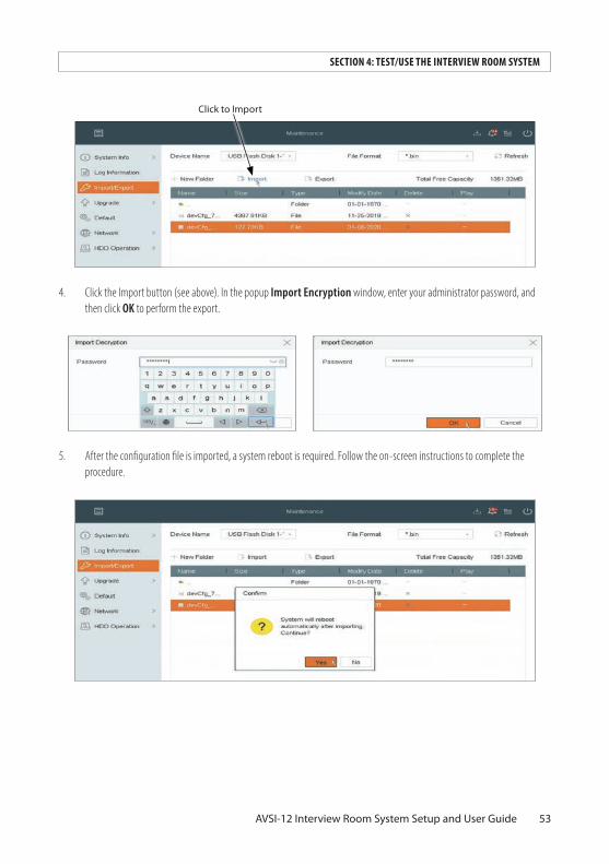
Click to Import
4. Click the Import button (see above). In the popup Import Encryption window, enter your administrator password, and then click OK to perform the export.
5. After the configuration file is imported, a system reboot is required. Follow the on-screen instructions to complete the procedure.

54 www.Observint.com
APPENDIX A: PLAYBACK SCREEN CONTROLS
APPENDIX A Playback Screen ControlsFor more information about the Playback features of your AVSI-12 system, refer to the ALIBI™ Embedded Video Recorder Firmware V4 .20 .00 User Manual downloadable from AlibiSecurity.com or your ALIBI security products vendor.
A.1 Playback screen basic controls
Video playback windowChannel panelSearch field
Time panel (calendar) Toolbar
Play head, timestampSwitch to sub-stream
Full
Screen splitGet external file
Show sub-periodsClip
Smart play strategyVideo clip Play controls Legend
Playback mode select TagDigital zoom
Mute - listen
Lock file
Smart search optionsMotion Detect
Intrusion DetectClear search option
Line crossing detectTimeline width
55AVSI-12 Interview Room System Setup and User Guide
APPENDIX A: PLAYBACK SCREEN CONTROLS
Notes:
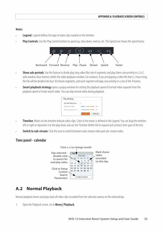
• Legend: Legend defines the type of video clips marked on the timeline
• Play Controls: Use the Play Control buttons to speed up, slow down, reverse, etc. The Speed icon shows the speed factor.
Play - Pause SlowerReverseForwardBackward Speed Faster
• Show sub-periods: Use this feature to divide play long video files into 4 segments and play them concurrently in a 2×2 split window (four frames) within the video playback window. For instance, if you are playing a video file that is 2 hours long, the file will be divided into four 30 minute segments, and each segment will play concurrently in a one of the 4 frames.
• Smart playback strategy opens a popup window for setting the playback speed of normal video separate from the playback speed of Smart search video. You can skip normal video during playback.
• Timeline: Marks on the timeline indicate video clips. Color of the marks is defined in the Legend. You can drag the timeline left or right to reposition it at the play head, and use the Timeline Width GUI to expand and contract time span of the line.
• Switch to sub-stream: Click this icon to switch between main stream video and sub-stream video.
Time panel - calendar
Click <, > to change month
Day selected - double-click to search for
and play video
Mark shows video recorded on this day
Click to Setup Custom
Search Parameters
A.2 Normal Playback
Normal playback shows and plays back all video clips recorded from the selected camera on the selected day.
1. Open the Playback screen. Go to Menu | Playback.

56 www.Observint.com
APPENDIX A: PLAYBACK SCREEN CONTROLS
2. In the Playback screen, check the box for the camera channel(s) you want to playback.
3. In the Time frame, the current day is identified. The recorder will search for available video in the selected month and mark each day that has recorded video available. In the screen below, the mark on the date shows video was recorded.
Mark shows video recorded on this day TimelineLegend
Play head, timestampPlayback mode (Normal)
Play controls

57AVSI-12 Interview Room System Setup and User Guide
APPENDIX B: ADVANCED RECORDER FEATURES
APPENDIX B Advanced Recorder FeaturesYour ALI-QVR4108H recorder is a state-of-the-art high performance digital video recorder. The extensive features of your ALIBI recorder are detailed in the Embedded Video Recorder Firmware V4.20.00 (or later) User Manual downloadable from AlibiSecurity.com or your ALIBI security products vendor. The most commonly used features are included below.
B.1 User Management
User accounts are created to control access to the system both at the recorder and when logging into the recorder from a remote computer. Each account has a User Name, Password, and a selection of permissions granted to the user. The recorder supports up to 32 user accounts. To add, edit, and delete user accounts, you must log into the recorder with admin user credentials. .
User Management - user configuration
User Camera Configuration settings
58 www.Observint.com
APPENDIX B: ADVANCED RECORDER FEATURES
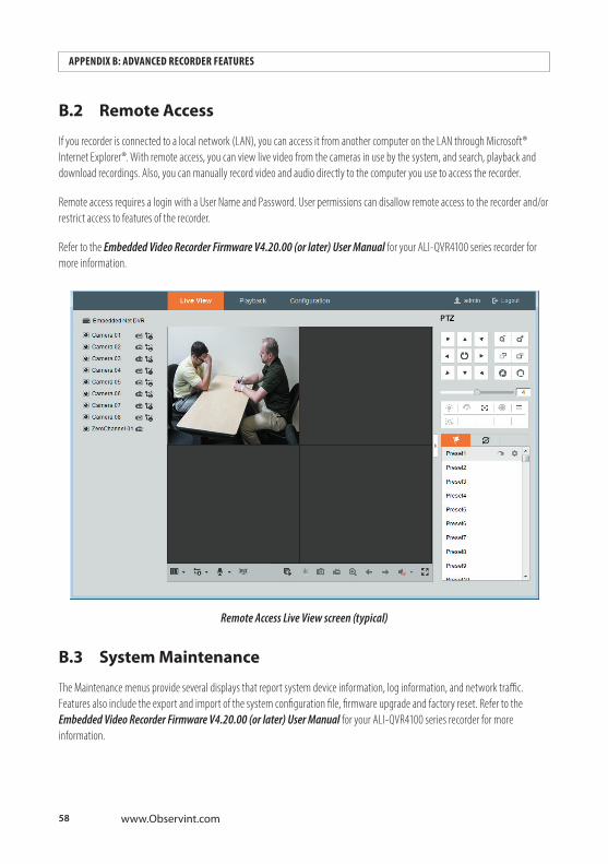
B.2 Remote Access
If you recorder is connected to a local network (LAN), you can access it from another computer on the LAN through Microsoft® Internet Explorer®. With remote access, you can view live video from the cameras in use by the system, and search, playback and download recordings. Also, you can manually record video and audio directly to the computer you use to access the recorder.
Remote access requires a login with a User Name and Password. User permissions can disallow remote access to the recorder and/or restrict access to features of the recorder.
Refer to the Embedded Video Recorder Firmware V4.20.00 (or later) User Manual for your ALI-QVR4100 series recorder for more information.
Remote Access Live View screen (typical)
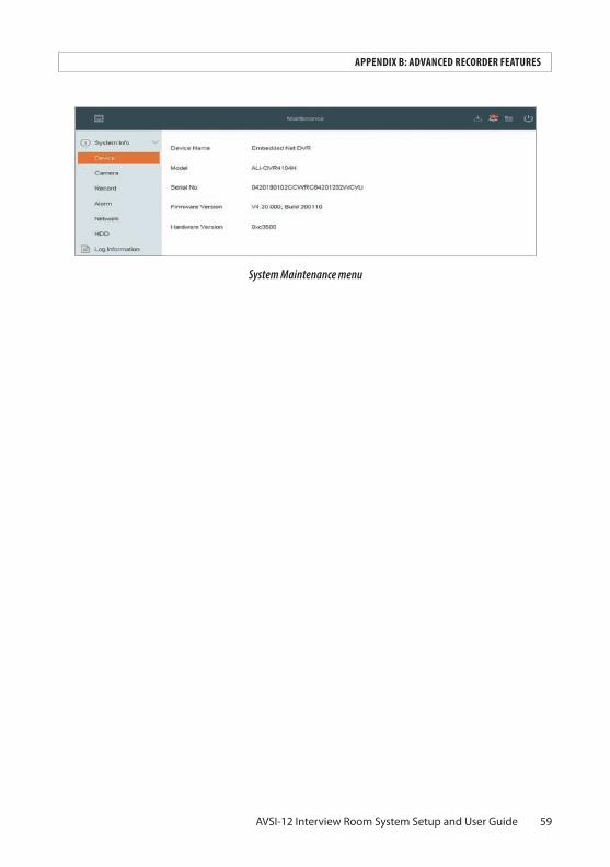
B.3 System Maintenance
The Maintenance menus provide several displays that report system device information, log information, and network traffic. Features also include the export and import of the system configuration file, firmware upgrade and factory reset. Refer to the Embedded Video Recorder Firmware V4.20.00 (or later) User Manual for your ALI-QVR4100 series recorder for more information.
59AVSI-12 Interview Room System Setup and User Guide
APPENDIX B: ADVANCED RECORDER FEATURES
System Maintenance menu