Embed Size (px)
Citation preview

AVR 7000 Audio/Video ReceiverOWNER’S MANUAL
Power for the digital revolution.™
®

2 TABLE OF CONTENTS
3 Introduction4 Safety Information4 Unpacking5 Front Panel Controls7 Front Panel Information Display9 Rear Panel Connections
11 Main Remote Control Functions14 Zone II Remote Control Functions15 Installation and Connections18 System Configuration20 Input Setup20 Surround Setup20 Delay Settings21 Crossover Frequency22 Speaker Setup23 Output Level Adjustment25 Operation25 Basic Operation25 Source Selection25 Surround Mode Selection26 Surround Mode Chart27 Digital Audio Playback29 Tuner Operation29 Tape Recording29 Output Level Trim Adjustment30 6-Channel Direct Input31 Advanced Features31 Front Panel Input/Output
Connections31 Display Brightness31 Turn On Volume Level32 OSD Settings33 Multiroom Operation34 Programming the Remote34 Direct Code Entry34 Auto Search Method34 Code Readout35 Learning Codes From a Remote35 Macro Programming36 Programmed Device Functions36 Volume Punch-Through37 Reassigning Device Control
Selectors37 Erasing Learned Codes38 Function List39 Setup Code Tables46 Troubleshooting Guide46 Processor Reset47 Technical Specifications
AVR 7000 Audio/Video Receiver
Typographical ConventionsIn order to help you use this manual with the remote control, front-panel controls and rear-panelconnections, certain conventions have been used.
EXAMPLE – (bold type) indicates a specific remote control or front-panel button, or rear-panel connection jack
EXAMPLE – (OCR type) indicates a message that is visible on the front-panel information display
EXAMPLE – (outlined type) indicates a lit indicator in the front-panel information display
1 – (number in a square) indicates a specific front-panel control
¡ – (number in a circle) indicates a rear-panel connection
a – (number in an oval) indicates a button or indicator on the remote
A – (letter in a square) indicates an indicator in the front-panel display
å – (letter in an oval) indicates a button on the Zone II remote

3 INTRODUCTION
Introduction
Thank you for choosing Harman Kardon!With the purchase of a Harman Kardon AVR 7000 you are about to begin many yearsof listening enjoyment. The AVR 7000 has beencustom designed to provide all the excitementand detail of movie sound tracks and everynuance of musical selections. With onboardDolby* Digital and DTS† decoding, the AVR 7000 delivers six discrete channels ofaudio that take advantage of the digital soundtracks from the latest DVD and LD releases andDigital Television broadcasts.
While complex digital systems are hard at work within the AVR 7000 to make all ofthis happen, hookup and operation are simple.Color-keyed connections, a backlit, programma-ble remote control, and on-screen menus makethe AVR 7000 easy to use. To obtain the maxi-mum enjoyment from your new receiver, weurge you to take a few minutes to readthrough this manual. This will ensure that connections to speakers, source playback unitsand other external devices are made properly.In addition, a few minutes spent learning thefunctions of the various controls will enableyou to take advantage of all the power theAVR 7000 is able to deliver.
If you have any questions about this product,its installation or its operation, please contactyour retailer or custom installer. They are yourbest local source of information.
Description and FeaturesThe AVR 7000 is among the most versatile andmulti-featured A/V receivers available, incorpo-rating a wide range of listening options. Inaddition to Dolby Digital and DTS decoding fordigital sources, a broad choice of analog sur-round modes are available for use with sourcessuch as CD, VCR, TV broadcasts and the AVR’sown FM/AM tuner. Along with Dolby Pro Logic*,Dolby 3 Stereo and custom Hall and Theater
modes, only Harman Kardon receivers offerLogic 7® to create a wider, more envelopingfield environment and more defined fly-oversand pans. The AVR 7000 is also the only receiver that offers HDCD® decoding to providethe most realistic playback of CDs when a digi-tal connection is used. Another Harman Kardonexclusive is VMAx™, which uses proprietary processing to create an open, spacious soundfield even when only two front speakers areavailable.
No matter how sophisticated your system com-ponents, the AVR 7000 is able to accommodatethem. In addition to five inputs with audio,composite video and S-Video, the AVR 7000features two component video inputs to ensurethe utmost in picture quality. Audio is accom-modated by two additional audio-only inputs,four digital audio inputs and two digital audiooutputs. A separate six-channel direct input isalso available to ensure compatibility withfuture audio systems.
Despite the wide range of inputs available,selecting between them is simple, using a back-lit remote control that operates the AVR and upto seven additional devices. Codes may be pro-grammed into the remote either from an exten-sive internal database or via a learning method.
The AVR 7000’s flexibility and power extendbeyond your main home theater or listeningroom. The AVR includes a sophisticated multi-zone control system that allows you to selectone source for use in the main room and a dif-ferent one in a second room. Both compositevideo and S-Video, as well as audio, are routedto the remote room location, with completecontrol over volume provided by a separateinfrared control link. To make it easy to operatethe AVR 7000 from a remote room, a separateZone II remote is included.
The AVR 7000’s powerful amplifier usestraditional Harman Kardon high-current designtechnologies to meet the wide dynamic rangeof any program selection.
Harman Kardon invented the high-fidelityreceiver more than forty-seven years ago. Withstate-of-the-art circuitry and time-honored cir-cuit designs, the AVR 7000 is one of the finestreceivers ever offered by Harman Kardon.
■ Onboard Dolby Digital and DTSDecoding Using Crystal® Chip Technology
■ Harman Kardon’s Exclusive Logic 7 andVMAx Modes
■ HDCD Decoding for Superb CDPlayback
■ Component Video Switching
■ Multiple Coax and Optical DigitalAudio Inputs and Outputs
■ Front Panel Input Jacks Switchable toInput or Output
■ Backlit Remote with Both InternalCodes and Learning Capability
■ On-Screen Menu and Display System
■ 6-Channel Direct Input, Preamp Output and Main Amp Input Jacks Permit Easy Expansion and Provide for Future Formats
■ Sophisticated Multizone ControlSystem with Separate Remote
CAUTIONRISK OF ELECTRIC SHOCK
DO NOT OPEN
CAUTION: To prevent electric shock, do not remove the grounding plug on the power cord, or use any plug
or extension cord that does not have a grounding plug provided.
Make certain that the AC outlet is properly grounded.
Do not use an adapter plug with this product.
The lightning flash with arrowhead symbol, within an equilateral triangle, is intended to alert the user to the presence of uninsulated “dangerous voltage” within the product’s
enclosure that may be of sufficient magnitude to constitute a risk of electric shock to persons.
The exclamation point within an equilateral triangle is intended to alert the user to the presence of important operating and maintenance (servicing) instructions in the
literature accompanying the appliance.

4 SAFETY INFORMATION
Safety Information
Important Safety Information
Verify Line Voltage Before UseYour AVR 7000 has been designed for use with120-volt AC current. Connection to a line volt-age other than that for which it is intended can create a safety and fire hazard and maydamage the unit.
If you have any questions about the voltagerequirements for your specific model, or aboutthe line voltage in your area, contact your sellingdealer before plugging the unit into a wall outlet.
Do Not Use Extension CordsTo avoid safety hazards, use only the powercord attached to your unit. We do not recom-mend that extension cords be used with thisproduct. As with all electrical devices, do notrun power cords under rugs or carpets or placeheavy objects on them. Damaged power cordsshould be replaced immediately by an author-ized service depot with a cord meeting factoryspecifications.
Handle the AC Power Cord GentlyWhen disconnecting the power cord from anAC outlet, always pull the plug, never pull thecord. If you do not intend to use the unit forany considerable length of time, disconnect theplug from the AC outlet.
Do Not Open the CabinetThere are no user-serviceable componentsinside this product. Opening the cabinet maypresent a shock hazard, and any modificationto the product will void your guarantee. If wateror any metal object such as a paper clip, wireor a staple accidentally falls inside the unit, dis-connect it from the AC power source immedi-ately, and consult an authorized service station.
CATV or Antenna GroundingIf an outside antenna or cable system is con-nected to this product, be certain that it isgrounded so as to provide some protectionagainst voltage surges and static charges.Section 810 of the National Electrical Code,ANSI/NFPA No. 70-1984, provides informationwith respect to proper grounding of the mastand supporting structure, grounding of the lead-in wire to an antenna discharge unit, size ofgrounding conductors, location of antenna dis-charge unit, connection to grounding electrodesand requirements of the grounding electrode.
NOTE TO CATV SYSTEM INSTALLER: Thisreminder is provided to call the CATV (Cable
TV) system installer’s attention to article 820-40 of the NEC that provides guidelines forproper grounding and, in particular, specifiesthat the cable ground shall be connected to thegrounding system of the building, as close tothe point of cable entry as possible.
Installation Location■ To assure proper operation and to avoid the
potential for safety hazards, place the uniton a firm and level surface. When placing theunit on a shelf, be certain that the shelf andany mounting hardware can support theweight of the product.
■ Make certain that proper space is providedboth above and below the unit for ventila-tion. If this product will be installed in a cabinet or other enclosed area, make certainthat there is sufficient air movement withinthe cabinet. Under some circumstances a fanmay be required.
■ Do not place the unit directly on a carpetedsurface.
■ Avoid installation in extremely hot or coldlocations, or an area that is exposed to directsunlight or heating equipment.
■ Avoid moist or humid locations.
■ Do not obstruct the ventilation slots on thetop of the unit, or place objects directlyover them.
CleaningWhen the unit gets dirty, wipe it with a clean,soft, dry cloth. If necessary, wipe it with a softcloth dampened with mild soapy water, then afresh cloth with clean water. Wipe dry immedi-ately with a dry cloth. NEVER use benzene,aerosol cleaners, thinner, alcohol or any othervolatile cleaning agent. Do not use abrasivecleaners, as they may damage the finish of metalparts. Avoid spraying insecticide near the unit.
Moving the UnitBefore moving the unit, be certain to discon-nect any interconnection cords with other com-ponents, and make certain that you disconnectthe unit from the AC outlet.
Important Information for the UserThis equipment has been tested and found tocomply with the limits for a Class-B digitaldevice, pursuant to Part 15 of the FCC Rules.The limits are designed to provide reasonableprotection against harmful interference in aresidential installation. This equipment gener-ates, uses and can radiate radio-frequency energyand, if not installed and used in accordance
with the instructions, may cause harmful inter-ference to radio communication. However, thereis no guarantee that harmful interference willnot occur in a particular installation. If thisequipment does cause harmful interference toradio or television reception, which can bedetermined by turning the equipment off andon, the user is encouraged to try to correct theinterference by one or more of the followingmeasures:
■ Reorient or relocate the receiving antenna.
■ Increase the separation between the equip-ment and receiver.
■ Connect the equipment into an outlet on acircuit different from that to which thereceiver is connected.
■ Consult the dealer or an experiencedradio/TV technician for help.
This device complies with Part 15 of the FCCRules. Operation is subject to the following twoconditions: (1) this device may not cause harm-ful interference, and (2) this device must acceptinterference received, including interferencethat may cause undesired operation.
NOTE: Changes or modifications may causethis unit to fail to comply with Part 15 of theFCC Rules and may void the user’s authority tooperate the equipment.
Unpacking
The carton and shipping materials used to pro-tect your new receiver during shipment werespecially designed to cushion it from shock andvibration. We suggest that you save the cartonand packing materials for use in shipping if youmove, or should the unit ever need repair.
To minimize the size of the carton in storage,you may wish to flatten it. This is done by care-fully slitting the tape seams on the bottom andcollapsing the carton. Other cardboard insertsmay be stored in the same manner. Packingmaterials that cannot be collapsed should besaved along with the carton in a plastic bag.
If you do not wish to save the packaging mate-rials, please note that the carton and other sec-tions of the shipping protection are recyclable.Please respect the environment and discardthose materials at a local recycling center.

5 FRONT PANEL CONTROLS
1 Main Power Switch: Press this button toapply power to the AVR 7000. When theswitch is pressed in, the unit is placed in aStandby mode, as indicated by the amber LED3 surrounding the System Power Control2. This button MUST be pressed in to oper-ate the unit. To turn the unit off and preventthe use of the remote control, this switchshould be pressed until it pops out from thefront panel so that the word “OFF” may beread at the top of the switch.
NOTE: In normal operation this switch is left inthe “ON” position.
2 System Power Control: When the MainPower Switch 1 is “ON,” press this button
to turn on the AVR 7000; press it again to turnthe unit off. Note that the Power Indicatorsurrounding the switch 3 will turn greenwhen the unit is on.
3 Power Indicator: This LED will illuminatein amber when the unit is in the Standby modeto signal that the unit is ready to be turned on.When the unit is in operation, the indicator willturn green.
4 Headphone Jack: This jack may be used tolisten to the AVR 7000’s output through a pair ofheadphones. Be certain that the headphoneshave a standard 1/4" stereo phone plug. Notethat the main room speakers will automaticallybe turned off when the headphone jack is in use.
5 Selector Buttons: When you are establish-ing the AVR 7000’s configuration settings, usethese buttons to select from the choices available,as shown in the Information Display Ò.
6 Tone Mode: Pressing this button enablesor disables the Bass and Treble tone controls.When the button is pressed so that the wordsTONE IN appear in the Main InformationDisplay Ò, the settings of the Bass # andTreble ^ controls will affect the output sig-nals. When the button is pressed so that thewords TONE OUT appear in the MainInformation Display Ò, the output signal willbe “flat,” without any bass or treble alteration.
Front Panel Controls
1 Main Power Switch2 System Power Control3 Power Indicator4 Headphone Jack5 Selector Buttons6 Tone Mode7 Surround Mode Selector8 Tuning Selector9 Tuner Band Selector) Preset Stations Selector
! Input Source Selector@ FM Mode Selector# Bass Control$ Video 4 Input Jacks% Video 4 Status Indicator^ Treble Control& Balance Control* Volume Control( Set ButtonÓ Input Indicators
Ô Delay Digital Input SelectorÒ Information DisplayÚ Channel Select ButtonÛ Speaker Select ButtonÙ Test Tone Selectorı Surround Mode Indicatorsˆ Remote Sensor Window
9 ) ! @ #$ %
^
&
Ó
3 4 5 6 7 8
1
2
(
*
Ô Ò Ú Û ı Ù ̂

6 FRONT PANEL CONTROLS
Front Panel Controls
7 Surround Mode Selector: Press this but-ton to change the surround mode by scrollingthrough the list of available modes. Note thatdepending on the type of input, some modesare not always available. (See page 25 for moreinformation about surround modes.)
8 Tuning Selector: Press the left side of thebutton to tune lower frequency stations and theright side of the button to tune higher frequencystations. When a station with a strong signal isreached, the TUNED indicator U will illumi-nate in the Information Display Ò .
To tune manually, tap the button lightly andnote that the tuner will step up one frequencyincrement per button press. When the button isheld for a few seconds you will note that theunit will quickly search the frequency band.Release it once the fast tuning starts and thetuner will automatically scan for the next stationwith an acceptable signal and then stop.
9 Tuner Band Selector: Pressing this buttonwill automatically switch the AVR to the Tunermode. Pressing it again will switch between theAM and FM frequency bands. (See page 29 formore information on the tuner.)
) Preset Stations Selector: Press this but-ton to select stations that have been enteredinto the preset memory. (See page 29 for moreinformation on tuner programming.)
! Input Source Selector: Press this buttonto change the input by scrolling through the listof input sources.
@ FM Mode Selector: Press this button toselect Auto or Manual tuning. When the buttonis pressed so that the AUTO Indicator V lights,the tuner will search for the next station with anacceptable signal when the Tuning Selector8xé is pressed. When the button ispressed so that the AUTO Indicator V is not lit,each press of the Tuning Selector 8xéwill increase the frequency. (See page 29 formore information on using the tuner.)
# Bass Control: Turn this control to modifythe low frequency output of the left/right chan-nels by as much as ±10dB. Set this control to asuitable position for your taste or room acoustics.
$ Video 4 Input Jacks: These audio/videojacks may be used for temporary connection tovideo games or portable audio/video productssuch as camcorders and portable audio players.
In normal use, they are an input that may beselected by pressing the Input SourceSelector ! on the front panel, or the Video4 Selector on either remote mç. Thesejacks may also be configured as an audio/videooutput, that will make a dub of the currentlyselected source when connected to an externalrecorder or camcorder. To change the jacks fromtheir default setting as an input to an output,use the Advanced Menu in the OSD system.(See page 31 for more information on using theVideo 4 jacks as a record output.)
% Video 4 Status Indicator: This indicatorwill normally be green to show that the Video 4jacks are operating as an input source. Whenthe jacks have been configured as an output,the indicator will turn red to show that they arebeing used for recording. (See page 31 formore information on using the Video 4 jacks.)
^ Treble Control: Turn this control to modifythe high frequency output of the left/right chan-nels by as much as ±10dB. Set this control to asuitable position for your taste or room acoustics.
& Balance Control: Turn this control tochange the relative volume for the frontleft/right channels.
NOTE: For proper operation of the surroundmodes this control should be at the midpoint or “12 o’clock” position.
* Volume Control: Turn this knob clockwiseto increase the volume, counterclockwise todecrease the volume. If the AVR is muted,adjusting volume control will automaticallyrelease the unit from the silenced condition.
( Set Button: When making choices duringthe setup and configuration process, press thisbutton to enter the desired setting as shown in the Information Display Ò into the AVR 7000’s memory. The set button may also be used to change the display brightness.(See page 31.)
Ó Input indicators: A green LED will light infront of the input that is currently being used asthe source for the AVR 7000.
Ô Delay: Press this button to begin thesequence of steps required to enter delay timesettings. (See pages 20–21 for more informa-tion on delay times.)
Digital Input Selector: When playing asource that has a digital output, press this button to select between the Optical · andCoaxial ° Digital inputs. (See pages 27–29for more information on digital audio.)
Ò Information Display: This display deliv-ers messages and status indications to help youoperate the receiver. (See pages 7–8 for a com-plete explanation of the Information Display.)
Ú Channel Select Button: Press this buttonto begin the process of trimming the channeloutput levels using an external audio source.(For more information on output level trimadjustment, see page 29.)
Û Speaker Select Button: Press this buttonto begin the process of selecting the speakerpositions that are used in your listening room.(See page 22 for more information on setupand configuration.)
Ù Test Tone Selector: Press this button tobegin the process of adjusting the channel out-put levels using the internal test tone as a ref-erence. (For more information on output leveladjustment, see page 23.)
ı Surround Mode Indicators: A green LEDwill light in front of the surround mode that iscurrently in use.
ˆ Remote Sensor Window: The sensorbehind this window receives infrared signalsfrom the remote control. Aim the remote at thisarea and do not block or cover it unless anexternal remote sensor is installed.

7 FRONT PANEL INFORMATION DISPLAY
Front Panel Information Display
A
B C D F M NJ LK
P
QRSTUW V
OE G H I
X
A Bitstream IndicatorsB Dolby Digital IndicatorC Coaxial Source IndicatorsD Analog Dolby Surround Mode IndicatorsE Optical Source IndicatorsF Analog Input IndicatorG Hall Mode IndicatorsH VMAx Mode Indicator
I Theater Mode IndicatorJ Logic 7 Mode IndicatorsK DTS Mode IndicatorL Preset Number/Sleep TimerM OSD IndicatorN Night Mode IndicatorO Multiroom IndicatorP Speaker/Channel Input Indicators
Q Sleep IndicatorR Preset IndicatorS Memory IndicatorT Stereo IndicatorU Tuned IndicatorV Auto IndicatorW Main Information DisplayX Mute Indicator
A Bitstream™ Indicators: When the selectedinput is a digital source, one of these indicators willlight to display the specific type of signal in use.
B Dolby Digital Indicator: This indicatorilluminates when a Dolby Digital source is beingplayed.
C Coaxial Source Indicators: These indica-tors light to show when one of the two CoaxialDigital Inputs has been selected.
D Analog Dolby Surround ModeIndicators: These indicators illuminate whenone of the analog (matrix) Dolby Surroundmodes is in use.
E Optical Source Indicators: These indica-tors light to show when one of the two OpticalDigital Inputs has been selected.
F Analog Input Indicator: This indicatorlights when an analog input source has beenselected.
G Hall Mode Indicators: These indicatorslight when one of the Hall modes has beenselected.
H VMAx Mode Indicator: This indicator illu-minates to show that the VMAx mode is in use.
I Theater Mode Indicator: This indicator illu-minates to show that the Theater mode is in use.
J Logic 7 Mode Indicators: These indica-tors illuminate when the Logic 7 mode is inuse. LOGIC 7C appears for the Cinema ver-
sion of Logic 7, LOGIC 7M appears for theMusic version of Logic 7.
K DTS Mode Indicator: This indicator illumi-nates when a DTS-encoded source is playing.
L Preset Number/Sleep Timer: When thetuner is in use, these numbers indicate the spe-cific preset memory location in use. (See page29 for more information on preset stations.)When the Sleep function is in use, these num-bers show how many minutes remain beforethe unit goes into the Standby mode.
M OSD Indicator: When the OSD system is inuse, this indicator lights to remind you that theother indicators in this display do not functionwhen the On Screen Display is being used.
N Night Mode Indicator: This indicatorlights when the AVR 7000 is in the Night mode,which preserves the dynamic range of digitalprogram material at low volume levels.
O Multiroom Indicator: This indicator lightswhen the multiroom system is active. Note thatit will remain lit when the multiroom system isin use even though the main room system is inthe Standby mode and all other indicators aredark. (See page 33 for more information on theMultiroom system.)
P Speaker/Channel Input Indicators: Theseindicators are multipurpose, indicating either thespeaker type selected for each channel or theincoming data-signal configuration. The left,center, right, right surround and left surround
speaker indicators are composed of three boxes,while the subwoofer is a single box. The centerbox lights when a “Small” speaker is selected,and the two outer boxes light when “Large”speakers are selected. When none of the boxesare lit for the center, surround or subwooferchannels, no speaker has been selected for thatposition. (See page 22 for more information onconfiguring speakers.) The letters inside each ofthe center boxes display active input channels.For standard analog inputs, only the L and R willlight, indicating a stereo input. When a digitalsource is playing, the indicators will light to dis-play the channels begin received at the digitalinput. When the letters flash, the digital inputhas been interrupted. See page 28 for moreinformation on the Channel Indicators.
Q Sleep Indicator: This indicator lights whenthe Sleep function is in use. The numbers in thePreset/Sleep Number Indicators will show theminutes remaining before the AVR 7000 goesinto the Standby mode. (See page 25 for moreinformation on the Sleep function.)
R Preset Indicator: This indicator lightswhen the tuner in use to show that the PresetNumber/Sleep Timer L is showing the sta-tion’s preset memory number. (See page 29 formore information on tuner presets.)
S Memory Indicator: This indicator flasheswhen entering presets and other informationinto the tuner’s memory.

8 FRONT PANEL INFORMATION DISPLAY
Front Panel Information Display
T Stereo Indicator: This indicator illuminateswhen an FM station is being tuned in stereo.
U Tuned Indicator: This indicator illuminateswhen a station is being received with sufficient sig-nal strength to provide acceptable listening quality.
V Auto Indicator: This indicator illuminateswhen the tuner’s Auto mode is in use.
W Main Information Display: This displayshows messages relating to the status, inputsource, surround mode, tuner, volume level orother aspects of unit’s operation.
X Mute Indicator: This indicator illuminatesto remind you that the AVR 7000’s output hasbeen silenced by pressing the Mute button f
. Press the Mute button again to return tothe previously selected output level.I

9 REAR PANEL CONNECTIONS
Rear Panel Connections
fl ‡ °
‹ ¤
›
‚ ¶ §
fi
⁄ •
· abcdefghij
ª £ ™ ¢ ¡ ∞
-
NOTE: For all video inputs and outputs f gh i j, the same number is used to indicatethe audio, composite-video and S-Video connec-tions related to that input. This accounts for thesame number appearing in more than one placeon the rear-panel drawing.
¡ AM Antenna™ FM Antenna£ 6-Channel Direct Inputs¢ CD Inputs∞ Component Video Outputs§ Video 2 Component Video Inputs¶ DVD Component Video Inputs• Tape Inputsª Speaker Outputs‚ Tape Outputs
⁄ Amplifier Inputs¤ Unswitched AC Accessory Outlet‹ Switched AC Accessory Outlets› AC Power Cordfi Subwoofer Outputfl Preamp Outputs‡ Digital Audio Outputs° Coaxial Digital Inputs· Optical Digital Inputsa Remote IR Output
b Multiroom IR Inputc Remote IR Inputd Multiroom Outputse Video Monitor Outputsf Video 3 Inputsg Video 2 Inputsh Video 1 Outputsi Video 1 Inputsj DVD Inputs

10 REAR PANEL CONNECTIONS
Rear Panel Connections
¡ AM Antenna: Connect the AM loop antennasupplied with the receiver to these terminals. If anexternal AM antenna is used, make connectionsto the AM and GND terminals in accordancewith the instructions supplied with the antenna.
™ FM Antenna: Connect the supplied indoor orthe optional external FM antenna to this terminal.
£ 6-Channel Direct Inputs: If an externaldigital audio decoder is used, connect the out-puts of that decoder to these jacks.
¢ CD Inputs: Connect these jacks to the out-put of a compact disc player or CD changer.
∞ Component Video Outputs: Connectthese outputs to the component video inputs ofa video projector or monitor. When a sourceconnected to one of the two ComponentVideo Inputs §¶ is selected the signal willbe sent to these jacks.
§ Video 2 Component Video Inputs:Connect the Y/Cr/Cb component video outputsof a set top converter box or other video prod-uct to these jacks.
¶ DVD Component Video Inputs: Connectthe Y/Cr/Cb component video outputs of a DVDplayer to these jacks.
• Tape Inputs: Connect these jacks to thePLAY/OUT jacks of an audio recorder.
ª Speaker Outputs: Connect the thesejacks to the matching + or – terminals on yourspeakers. When making speaker connections,always make certain to maintain correct polarityby connecting the red (+) terminals on the AVRto the red terminals on the speaker and theblack (–) terminals on the AVR to the black ter-minals on the speakers. (See page 15 for moreinformation on speaker polarity.)
‚ Tape Outputs: Connect these jacks to theRECORD/INPUT jacks of an audio recorder.
⁄ Amplifier Inputs: When the jumper pinsthat link the Preamp Outputs fl with theseinputs are removed, these jacks may be used toconnect an external source or the AVR7000’smultiroom system to the internal amplifiers.(See page 17 for more information on usingthese connections.)
¤ Unswitched AC Accessory Outlet: Thisoutlet may be used to power any AC device.The power will remain on at this outlet regard-less of whether the AVR 7000 is on or off.
‹ Switched AC Accessory Outlets: Theseoutlets may be used to power any device thatyou wish to have turn on when the unit isturned on with the System Power Controlswitch 2.
› AC Power Cord: Connect the AC plug toan unswitched AC wall output.
fi Subwoofer Output: Connect this jack tothe line-level input of a powered subwoofer. Ifan external subwoofer amplifier is used, con-nect this jack to the subwoofer amplifier input.
fl Preamp Outputs: When the jumper pinsthat link the Amplifier Inputs ⁄ with theseoutputs are removed, these jacks may be con-nected to an external power amplifier.
‡ Digital Audio Outputs: Connect thesejacks to the matching digital input connectoron a digital recorder such as a CD-R orMiniDisc recorder.
° Coaxial Digital Inputs: Connect the coaxdigital output from a DVD player, HDTV receiver,LD player or CD player to these jacks. The signalmay be either a Dolby Digital signal, DTS signalor a standard PCM digital source.
· Optical Digital Inputs: Connect the opti-cal digital output from a DVD player, HDTVreceiver, LD player or CD player to these jacks.The signal may be either a Dolby Digital signal,a DTS signal or a standard PCM digital source.
a Remote IR Output: This connection per-mits the IR sensor in the receiver to serve otherremote controlled devices. Connect this jack tothe “IR IN” jack on Harman Kardon or othercompatible equipment.
b Multiroom IR Input: Connect the output ofan IR sensor in a remote room to this jack tooperate the AVR 7000’s multiroom control system.
c Remote IR Input: If the AVR 7000’sfront-panel IR sensor is blocked due to cabinetdoors or other obstructions, an external IR
sensor may be used. Connect the output ofthe sensor to this jack.
d Multiroom Outputs: Connect these jacksto the optional audio power amplifiers or videodisplay devices to view and listen to the sourceselected by the mulitroom system in a remoteroom.
e Video Monitor Outputs: Connect this jackto the composite or S-Video input of a TV moni-tor or video projector to view the on-screenmenus and the output of any standard videosource selected by the receiver’s video switcher.
f Video 3 Inputs: Connect these jacks to theaudio and video outputs of a TV tuner, Cable TVconverter box, satellite receiver or anotheraudio/video source.
g Video 2 Inputs: Connect these jacks to theaudio and video outputs of a TV Tuner, Cable TVconverter box, satellite receiver or any otheraudio/video source.
h Video 1 Outputs: Connect these jacks tothe audio and video RECORD/INPUT jacks ofa VCR.
i Video 1 Inputs: Connect these jacks to theaudio and video PLAY/OUT jacks of a VCR.
j DVD Inputs: Connect the analog audiooutputs and composite video output of a DVDor LD player to these jacks.

11 MAIN REMOTE CONTROL FUNCTIONS
● ●●●●●● ●
Main Remote Control Functions
AVR 7000
MULTI-ROOMNIGHT
kardon
SLEEP
SURR.CH.
SET
SPKR
MENU
SAT
AVR
ON
POWER
CH.
TEST
harman
CD
PREV.CH.DELAY
5
0
43
9
DIRECT
8
LIGHT
M3 M4CLEAR
DWN-PRESET-UP
DIGITAL
21
6 CH.
76
OSD
M1
MEMORY
M2
a
k
m
o
b
l
np
s
d
f
j
i
r
`z
28
29
30
31
34
32
x
q
t
u
w
y
v
33
35
c
e
g
g
h
TAPE DVD
T/VMUTE
GUIDE
EXIT
VID 4
VID 3
VID 2
VID 1
AM/FM
TUN-M
DWN-TUNING-UP
VOL.
VCRTV CBL
a Program Indicatorb AVR Selectorc CD/Tape/DVD Input Selectorsd Power Off Buttone Test Tonef Muteg ⁄ /¤ Buttonsh Channel Select Buttoni Set Buttonj ‹ Buttonk Digital Selectl 6-Ch. Direct Inputm Video Input Selectorsn AM/FM Tuner Selecto Tuner Modep Memory Buttonq Numeric Keysr Macro 1/2 Buttonss OSD Buttont Light Buttonu Direct/Macro 3 Buttonv Clear/Macro 4 Buttonw Preset Up/Downx Tuning Up/Downy Forward/Reverse Transport Buttonsz Night Mode` Multi-Room28 Delay/Prev. Ch.29 › Button30 Speaker Select31 Surround Mode Selector32 Volume Up/Down33 Sleep Button34 Video Remote Selectors35 IR Transmitter Window
NOTE: The function names shown here are eachbutton’s feature when used with the AVR. Mostbuttons have additional functions when usedwith other devices. See page 38 for a list ofthese functions.

12 MAIN REMOTE CONTROL FUNCTIONS
Main Remote Control Functions
IMPORTANT NOTE: The AVR 7000’s remotemay be programmed to control up to eightdevices, including the AVR 7000. Before usingthe remote, it is important to remember to pressthe Device Control Selector button b cthat corresponds to the unit you wish to operate. In addition, the AVR 7000’s remote is shipped from the factory to operate the AVR 7000 and most Harman Kardon CD or DVDplayers and cassette decks. The remote is alsocapable of operating a wide variety of otherproducts using the control codes that are part of the remote. Before using the remote withother products, follow the instructions on pages34–45 to program the proper codes for theproducts in your system.
It is also important to remember that many ofthe buttons on the remote take on differentfunctions, depending on the product selectedusing the Device Control Selectors. The descrip-tions shown here primarily detail the functionsof the remote when it is used to operate theAVR 7000. (See page 38 for information aboutalternate functions for the remote’s buttons.)
a Program Indicator: This three-color indi-cator is used to guide you through the processof learning commands from a remote into theAVR’s remote code memory. (See page 35 forinformation on learning IR codes.)
b AVR Selector: Pressing this button willswitch the remote so that it will operate theAVR’s functions. If the AVR is in the Standbymode, it will also turn the AVR on.
c CD/Tape/DVD Input Selectors: Pressingone of these buttons will perform three actionsat the same time. First, if the AVR is not turnedon, this will power up the unit. Next, it willselect the source shown on the button as theinput to the AVR. Finally, it will change theremote control so that it controls the deviceselected. After pressing one of these buttonsyou must press the AVR Selector button bagain to operate the AVR’s functions with theremote.
d Power Off Button: Press this button toplace the unit in the Standby mode. Note thatthis will turn off the main room functions, but if the Multiroom system is activated, it will continue to function.
e Test Tone: Press this button to begin thesequence used to calibrate the AVR 7000’s out-put levels. (See page 23 for more information oncalibrating the AVR 7000.)
f Mute: Press this button to momentarilysilence the AVR 7000 or TV set being con-trolled, depending on which device has beenselected.
When the AVR 7000 remote is being pro-grammed to operate another device, this buttonis pressed with the Device Control Selectorbutton b to begin the programmingprocess. (See page 34 for more information onprogramming the remote.)
g ⁄/¤ Buttons: These are multi-purposebuttons. They will be used most frequently toselect a surround mode. To change the surroundmode, first press the SURR/CH ¤ button .Next press these buttons to scroll up or downthrough the list of surround modes that appear inthe Information Display 23.. These buttons arealso used to increase or decrease output levelswhen configuring the unit with either the inter-nal test tone or an external source. They arealso used to enter delay time settings after theDelay button has been pressed.
h Channel Select Button: This button isused to start the process of setting the AVR7000’s output levels to an external source. Oncethis button is pressed, use the ⁄/¤ buttons gto select the channel being adjusted, then pressthe Set button i, followed by the ⁄/¤ but-tons again, to change the level setting. (See page23 for more information.)
i Set Button: This button is used to entersettings into the AVR 7000’s memory. It is alsoused in the setup procedures for delay time,speaker configuration and channel output leveladjustment.
j ‹ Button: This button is used to changethe menu selection or setting during some ofthe setup procedures for the AVR.
k Digital Select: Press this button to assignone of the digital inputs ° · to a source.(See page 27 for more information on usingdigital inputs.)
l 6-Ch. Direct Input: Press this button toselect the component connected to the 6-Ch.direct Input £ as the source
m Video Input Selector: Press one of thesebuttons to select a video input as the listeningand viewing source.
n AM/FM Tuner Select: Press this button toselect the AVR’s tuner as the listening choice.
Pressing this button when a tuner is in use willselect between the AM and FM bands.
o Tuner Mode: Press this button when thetuner is in use to select between automatic tuning and manual tuning. When the button ispressed so that the AUTO indicator V goesout, pressing the Tuning buttons x8≠will move the frequency up or down in single-step increments. When the FM band is in use,pressing this button when a station’s signal isweak will change to monaural reception. (Seepage 29 for more information.)
p Memory Button: Press this button to enter a radio station into the AVR 7000’s presetmemory. After pressing the button the MEMORYindicator S will flash; you then have five sec-onds to enter a preset memory location usingthe Numeric Keys q. (See page 29 for moreinformation.)
q Numeric Keys: These buttons serve as aten-button numeric keypad to enter tuner presetpositions. They are also used to select channelnumbers when TV has been selected on theremote, or to select track numbers on a CD,DVD or LD player, depending on how theremote has been programmed.
r Macro 1/2 Buttons: These buttons areused to recall or enter the programmingsequence for a preprogrammed Macrosequence. (See page 36 for more information on programming and using Macros.)
s OSD Button: Press this button to activatethe On Screen Display (OSD) system used to setup or adjust the AVR 7000’s parameters.
t Light Button: Press this button to activatethe remote’s built-in backlight for better legibility of the buttons in a darkened room.
u Direct/Macro 3 Button: This button hastwo functions. Pressing it when the tuner is inuse will start the sequence for direct entry of astation’s frequency. After pressing the buttonsimply press the proper Numeric Keys q toselect a station. This button may also be usedto store or recall a macro sequence. (See page29 for more information on the tuner, and page36 for more information on programming andusing Macros.).
v Clear/Macro 4 Button: This button maybe used to store and recall a macro; it may alsobe programmed for use with other devices. (Seepage 36 for nore information on macros.)
28
31
34

13 MAIN REMOTE CONTROL FUNCTIONS
w Preset Up/Down: When the tuner is in use, press these buttons to scroll through the stations programmed into the AVR 7000’smemory. When some source devices, such asCD players, VCRs and cassette decks, are selected using the Device Control Selectorscç, these buttons may function as chapterstep or track advance.
x Tuning Up/Down: When the tuner is inuse, these buttons will tune up or down throughthe selected frequency band. If the Tuner Modebutton o@ has been pressed so that theAUTO indicator V is illuminated, pressing andholding either of the buttons for three secondswill cause the tuner to seek the next station withacceptable signal strength for quality reception.When the AUTO indicator V is NOT illuminat-ed, pressing these buttons will tune stations insingle-step increments. (See page 29 for moreinformation.)
y Forward/Reverse Transport Buttons:These buttons do not have any functions for the AVR, but they may be programmed for theforward/reverse play operation of a wide varietyof CD or DVD players, and audio or video-cassette recorders. (See page 34 for more information on programming the remote.)
z Night Mode: Press this button to activatethe Night mode. This mode is available in spe-cially encoded digital sources, and it preservesdialog (center channel) intelligibilty at low vol-ume levels.
` Multi-Room: Press this button to activatethe Multiroom system or to begin the processof changing the input or volume level for thesecond zone. (See page 33 for more informationon the Multiroom system.)
Delay/Prev Ch.: Press this button tobegin the process for setting the delay timesused by the AVR 7000 when processing sur-round sound. After pressing this button, thedelay times are entered by pressing the Setbutton i and then using the ⁄/¤ buttonsg to change the setting. Press the Set buttonagain to complete the process. (See page 20 formore information.)
› Button: Press this button to change asetting or selection when configuring many of theAVR’s settings.
Speaker Select: Press this button to begin the process of configuring the AVR 7000’s Bass Management System for usewith the type of speakers used in your system.Once the button has been pressed, use the⁄/¤ buttons g to select the channel youwish to set up. Press the Set button i andthen select another channel to configure.When all adjustments have been completed,press the Set button twice to exit the settingsand return to normal operation. (See page 22for more information.)
Surround Mode Selector: Press thisbutton to begin the process of changingthe surround mode. After the button hasbeen pressed, use the ⁄/¤ buttons g toselect the desired surround mode. (See page 25for more information.) Note that this button isalso used to tune channels when the TV isselected using the Device ControlSelector . When the AVR 7000 remote isbeing programmed for the codes of anotherdevice, this button is also used in the “AutoSearch” process. (See page 34 for more infor-mation on programming the remote.)
Volume Up/Down: Press these buttons toraise or lower the system volume.
Sleep Button: Press this button to placethe unit in the Sleep mode. After the timeshown in the display, the AVR 7000 will auto-matically go into the Standby mode. Each pressof the button changes the time until turn-off inthe following order:
Note that this button is also used to changechannels on your TV when the TV is selectedusing the Video Remote Selectors .
When the AVR 7000 remote is being pro-grammed for the codes of another device, thisbutton is also used in the “Auto Search” process.(See page 34 for more information on program-ming the remote.)
Video Remote Selectors: Press one ofthese buttons to use the remote to control thefunctions of the device shown on the button. (Formore information on programming the remote tooperate these devices, see pages 34–35.)
NOTE: As any of these buttons is pressed, itwill briefly flash red to confirm your selection.
IR Transmitter Window: Point this win-dow towards the AVR 7000 when pressing but-tons on the remote to make certain that infraredcommands are properly received.
35
34
34
90min
80min
70min
60min
50min
40min
30min
20min
10min OFF
33
32
34
31
30
29
28
Main Remote Control Functions

14 ZONE II REMOTE CONTROL FUNCTIONS
Zone II Remote Control Functions
å Power Off∫ AVR Selectorç Input Selectors∂ Transport Controls≠ Tuning Up/Down – Fast Playƒ Preset Up/Down – Track Skip© Disk Skip˙ Volume Up/Down
Mute
NOTE: The Zone II remote may be used ineither the same room where the AVR 7000 islocated, or it may be used in a separate roomwith an optional infrared sensor that is con-nected to the AVR 7000’s Multi IR input jackb. When it is used in the same room as theAVR, it will control the functions of the AVR orany compatible Harman Kardon products inthat room. When it is used in a separate room
via a sensor connected to the Multi IR Jack b,the buttons for power, input source, volume,mute and the tuner will control the source andvolume for the second zone, as connected tothe Multi Out Jacks d. (See page 33 for complete information on using the Multi-Roomsystem.)
I
å Power Off: When used in the roomwhere the AVR 7000 is located, press this but-ton to place the unit in Standby. When it isused in a remote room with a sensor that isconnected to the Multi IR jack b, this buttonturns the Multi-Room system on and off.
∫ AVR Selector: Press this button to turnon the AVR. The input in use when the unit waslast on will be selected.
ç Input Selectors: When the AVR is off,press one of these buttons to select a specificinput and turn the unit on. When the unit isalready in use, pressing one of these buttonswill change the input.
∂ Transport Controls: These buttons control the Play, Pause and Stop functions of compatible Harman Kardon CD, DVD andcassette players.
≠ Tuning Up/Down – Fast Play: Whenthe AVR’s tuner is selected as the input source,these buttons will tune up or down through thefrequencies of the chosen band. When a CD,DVD or cassette deck is selected, these buttonsactivate the Fast Play Forward or Fast PlayReverse functions.
ƒ Preset Up/Down – Track Skip: Whenthe AVR’s tuner is selected as the input source,these buttons will move up or down throughthe list of stations that have been stored in thepreset memory. When a CD or DVD player isselected, these buttons activate the forward orreverse track or chapter skip functions.
© Disc Skip: When a compatible HarmanKardon CD or DVD changer has been selected,these buttons activate the Disc Skip function.
˙ Volume Up/Down: When used in theroom where the AVR 7000 is located, press thisbutton to raise or lower the volume in thatroom. When it is used in a remote room with asensor that is connected to the Multi IR Jackb, this button will raise or lower the volume inthe remote room.
Mute: When used in the room where theAVR 7000 is located, press this button to tem-porarily silence the unit. When it is used in aremote room with a sensor that is connected tothe Multi IR Jack b, this button will tem-porarily silence the feed to the remote roomonly. Press the button again to return to theprevious volume level.
I
˙
å
∫
ç
∂
≠
ƒ
©
I
System InstallationAfter unpacking the unit, and placing it on a solidsurface capable of supporting its weight, you willneed to make the connections to your audio andvideo equipment.
Audio Equipment ConnectionsWe recommend that you use high-quality inter-connect cables when making connections tosource equipment and recorders to preserve theintegrity of the signals.
When making connections to audio sourceequipment or speakers it is always a good prac-tice to unplug the unit from the AC wall outlet.This prevents any possibility of accidentallysending audio or transient signals to the speak-ers that may damage them.
1. Connect the analog output of a CD player tothe CD inputs ¢.
NOTE: When the CD player has both fixed andvariable audio outputs it is best to use the fixedoutput unless you find that the input to thereceiver is so low that the sound is noisy, or sohigh that the signal is distorted.
2. Connect the analog Play/Out jacks of a cas-sette deck, MD, CD-R or other audio recorder tothe Tape In jacks •. Connect the analogRecord/In jacks on the recorder to the TapeOut jacks ‚ on the AVR 7000.
3. Connect the output of any digital sources to the appropriate input connections on theAVR 7000 rear panel. Note that the Opticaland Coaxial digital inputs °· may be used with a Dolby Digital or DTS source or the output of a conventional CD or LD player’sPCM (S/P-DIF) output.
4. Connect the Coaxial or Optical DigitalOutputs ‡ on the rear panel of the AVR to thematching digital input connections on a CD-R orMiniDisc recorder.
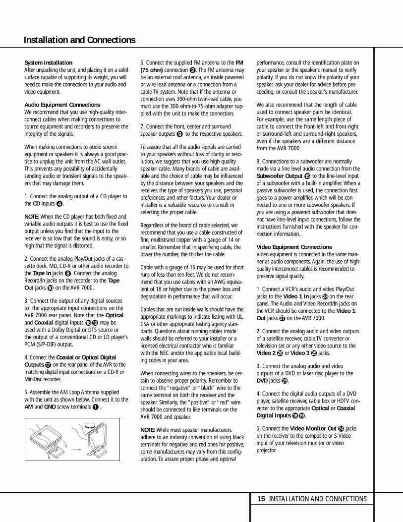
5. Assemble the AM Loop Antenna suppliedwith the unit as shown below. Connect it to theAM and GND screw terminals ¡ .
6. Connect the supplied FM antenna to the FM(75 ohm) connection ™. The FM antenna maybe an external roof antenna, an inside poweredor wire lead antenna or a connection from acable TV system. Note that if the antenna orconnection uses 300-ohm twin-lead cable, youmust use the 300-ohm-to-75-ohm adapter sup-plied with the unit to make the connection.
7. Connect the front, center and surround speaker outputs ª to the respective speakers.
To assure that all the audio signals are carriedto your speakers without loss of clarity or reso-lution, we suggest that you use high-qualityspeaker cable. Many brands of cable are avail-able and the choice of cable may be influencedby the distance between your speakers and thereceiver, the type of speakers you use, personalpreferences and other factors. Your dealer orinstaller is a valuable resource to consult inselecting the proper cable.
Regardless of the brand of cable selected, werecommend that you use a cable constructed offine, multistrand copper with a gauge of 14 orsmaller. Remember that in specifying cable, thelower the number, the thicker the cable.
Cable with a gauge of 16 may be used for shortruns of less than ten feet. We do not recom-mend that you use cables with an AWG equiva-lent of 18 or higher due to the power loss anddegradation in performance that will occur.
Cables that are run inside walls should have theappropriate markings to indicate listing with UL,CSA or other appropriate testing agency stan-dards. Questions about running cables insidewalls should be referred to your installer or alicensed electrical contractor who is familiarwith the NEC and/or the applicable local build-ing codes in your area.
When connecting wires to the speakers, be cer-tain to observe proper polarity. Remember toconnect the “negative” or “black” wire to thesame terminal on both the receiver and thespeaker. Similarly, the “positive” or “red” wireshould be connected to like terminals on theAVR 7000 and speaker.
NOTE: While most speaker manufacturersadhere to an industry convention of using blackterminals for negative and red ones for positive,some manufacturers may vary from this config-uration. To assure proper phase and optimal
performance, consult the identification plate onyour speaker or the speaker’s manual to verifypolarity. If you do not know the polarity of yourspeaker, ask your dealer for advice before pro-ceeding, or consult the speaker’s manufacturer.
We also recommend that the length of cableused to connect speaker pairs be identical.For example, use the same length piece ofcable to connect the front-left and front-rightor surround-left and surround-right speakers,even if the speakers are a different distancefrom the AVR 7000.
8. Connections to a subwoofer are normallymade via a line level audio connection from theSubwoofer Output fi to the line-level inputof a subwoofer with a built-in amplifier. When apassive subwoofer is used, the connection firstgoes to a power amplifier, which will be con-nected to one or more subwoofer speakers. Ifyou are using a powered subwoofer that doesnot have line-level input connections, follow theinstructions furnished with the speaker for con-nection information.
Video Equipment ConnectionsVideo equipment is connected in the same man-ner as audio components. Again, the use of high-quality interconnect cables is recommended topreserve signal quality.
1. Connect a VCR’s audio and video Play/Outjacks to the Video 1 In jacks i on the rearpanel. The Audio and Video Record/In jacks onthe VCR should be connected to the Video 1Out jacks h on the AVR 7000.
2. Connect the analog audio and video outputsof a satellite receiver, cable TV converter or television set or any other video source to theVideo 2 g or Video 3 f jacks.
3. Connect the analog audio and video outputs of a DVD or laser disc player to theDVD jacks j.
4. Connect the digital audio outputs of a DVDplayer, satellite receiver, cable box or HDTV con-verter to the appropriate Optical or CoaxialDigital Inputs °·.
5. Connect the Video Monitor Out e jackson the receiver to the composite or S-Videoinput of your television monitor or video projector.
15 INSTALLATION AND CONNECTIONS
Installation and Connections

16 INSTALLATION AND CONNECTIONS
Installation and Connections
6. If your DVD player and monitor both havecomponent video connections, connect thecomponent outputs of the DVD player to theDVD Component Video Inputs ¶. Notethat even when component video connectionsare used the audio connections should still bemade to either the analog DVD Audio Inputsj or any of the Coaxial or Optical DigitalInput jacks °·.
7. If another component video device is avail-able, connect it to the Video 2 ComponentVideo Input jacks §. The audio connectionsfor this device should be made to either theVideo 2 Input jacks g or any of the Coaxialor Optical Digital Input jacks °·.
8. If the component video inputs are used, con-nect the Component Video Output ∞ tothe component video inputs of your TV, projec-tor or display device.
Video Connection Notes:• When the component video jacks are used,
the on-screen menus will not be visible. Youmust switch to the standard composite or S-Video input on your TV to view those menus.
• The AVR 7000’s component video system isdesigned for standard video rate (NTSC/480i)video from DVD players and similar devices.While it may operate with high definition signals, the quality may be slightly less thanwith a direct connection.
• The AVR 7000 will accept either standardcomposite, S-Video or Y/Cr/Cb componentvideo signals. However, it will not convertcomposite or S signals to component video.
• Component or Composite video signals mayonly be viewed in their native formats.However, S-Video signals will be converted tostandard, composite video, and are viewablethrough the Composite Video MonitorOutput e.
System and Power Connections
The AVR 7000 is designed for flexible use withmultiroom systems, external control compo-nents and power amplifiers.
Main Room Remote Control ExtensionIf the receiver is placed behind a solid orsmoked glass cabinet door, the obstruction mayprevent the remote sensor from receiving com-mands. In this event, an optional remote sensormay be used. Connect the output of the remotesensor to the Remote IR Input jack c.
If other components are also prevented fromreceiving remote commands, only one sensor isneeded. Simply use this unit’s sensor or aremote eye by running a connection from theRemote IR Output jack a to the Remote IR Input jack on Harman Kardon or other com-patible equipment.
Multiroom IR LinkThe remote room IR receiver should be connectedto the AVR 7000 via standard coaxial cable. Plugthe IR connection cable into the Multiroom IRInput jack b on the AVR 7000’s rear panel.
If other Harman Kardon compatible sourceequipment is part of the main room installation,the Remote IR Output jack a on the rearpanel should be connected to the IR IN jack onthe CD player or cassette deck. This will enablethe remote room location to control sourceequipment functions in addition to the remoteroom input and volume.
NOTE: All remotely controlled componentsmust be linked together in a daisy chain.Connect the IR OUT jack of one unit to the IR IN of the next to establish this chain.
Multiroom Audio/Video ConnectionsDepending on the distance from theAVR 7000 to the remote room, two options (A and B) are available for audio connection:
A. Use high-quality, shielded audio interconnectcable from the AVR 7000’s location to theremote room. At the remote room, connect theinterconnect cable to a stereo power amplifier.The amplifier will be connected to the room’sspeakers. No volume control is required, as theAVR 7000 and the remote IR link will providethat function. At the AVR 7000, plug the audiointerconnect cables into the Multi-RoomOutput jacks d on the AVR 7000’s rear panel.
NOTE: The remote power amplifier must have signal sensing capability or be left on constantly toassure automatic operation at the remote room.
B. Place the amplifier that will provide power tothe remote location speakers in the same roomas the AVR 7000, and connect the MultiroomOutput jacks d on the rear panel of the AVRto the audio input of the remote room amplifier.Use the appropriate speaker wire to connect theoptional power amplifier to the remote speakers.High-quality wire of at least AWG14 is recom-mended for long multiroom connections.
The AVR 7000’s multiroom system is also capa-ble of sending either S-Video or standard com-posite video to the remote room location.Connect the video feeds for the remote locationto the Multiroom Output d video jacks.Note that standard S-Video cables may not pro-vide acceptable signal quality when used forruns longer than 35 feet. Consult your dealer orinstaller for additional cable options for S-Videoapplications. When running longer lengths ofcomposite video cable for multi-room applica-tions, we recommend that dual shield or quadshield RG-6 cable be used.
IMPORTANT NOTE: Any cables run inside wallsshould be CL3/FT4 rated, or carry any other certi-fication that is required by the NEC or state andlocal building and electrical codes. To avoid inter-ference, audio and speaker cables should not beparallel to, or run in the same conduits or pathwith, AC cables. If you have any questions aboutmultiroom wiring, consult your dealer, custominstaller or low-voltage electrical contractor.

17 INSTALLATION AND CONNECTIONS
Installation and Connections
External Audio Power AmplifierConnectionsIf desired, the AVR 7000 may be connected tooptional, external audio power amplifiers orused with equalizers or speaker systems thatrequire connection between the preamp andamplifier sections of a receiver.
To make these connections, remove the jumpersthat connect the Preamp Out jacks fl andAmplifier In jacks ⁄ for the channels to beused with external devices. Store the jumpers ina safe place so that the AVR may be used in itsnormal mode at a future date, if desired.
When an external amplifier is used, connect thePreamp Out jacks fl to the inputs on theamplifier. When an equalizer or speaker proces-sor is used, connect the Preamp Out jacks flto the inputs of the processor, and connect theoutputs of the processor back to the AmplifierIn jacks ⁄ on the AVR. Note that when exter-nal amplifiers or devices are used, the volumecontrol is still controlled by the AVR, althoughadditional volume controls on the externaldevice may impact the volume settings and out-put levels from the AVR.
External Audio Decoder ConnectionTo provide for ultimate flexibility, the AVR 7000may be used in conjunction with optional,external decoders for digital audio systemsother than the AVR 7000’s own built-in DolbyDigital and DTS decoding system or with DVDplayers using the DVD Audio Format. If anexternal decoder is used, connect the outputjacks of the decoder to the 6-Channel Directinputs £, making sure to match channels.
These jacks may also be used for connections todevices such as DVD players or High DefinitionTelevision (HDTV) sets or decoders that featurebuilt-in digital surround decoders. Although thedigital decoding system in the AVR 7000 will typi-cally provide audio performance that is superiorto other decoders, you may use these jacks toprovide an additional 6-channel input for connec-tion to a DVD player or HDTV set with a built-indecoder and discrete 6-channel analog outputs.
AC Power ConnectionsThis unit is equipped with three accessory ACoutlets. They may be used to power accessorydevices, but they should not be used with high-current draw equipment such as power ampli-fiers. The total power draw to each outlet maynot exceed 100 watts.
The Switched ‹ outlets will receive poweronly when the unit is on. This is recommendedfor devices that have no power switch or amechanical power switch that may be left inthe “ON” position.
NOTE: Many audio and video products go intoa Standby mode when they are used withswitched outlets, and cannot be fully turned onusing the outlet alone without a remote controlcommand.
The Unswitched ¤ outlet will receive poweras long as the unit is plugged into a poweredAC outlet.
Finally, when all connections are complete, plugthe power cord into a nonswitched 120-volt ACwall outlet. You’re almost ready to enjoy theAVR 7000!

18 SYSTEM CONFIGURATION
System Configuration
When all audio, video and system connectionshave been made, there are a few configurationadjustments that must be made. A few minutesspent to correctly configure and calibrate theunit will greatly add to your listening experience.
Speaker Selection and PlacementThe placement of speakers in a multichannelhome-theater system can have a noticeableimpact on the quality of sound reproduced.
No matter which type or brand of speakers isused, the same model or brand of speakershould be used for the front left, center andfront right speakers. This creates a seamlessfront soundstage and eliminates the possibilityof distracting sonic disturbances that occurwhen a sound moves across mismatched frontchannel speakers.
Speaker PlacementDepending on the type of center channelspeaker in use and your viewing device, placethe center speaker either directly above orbelow your TV, or in the center behind a perfo-rated front projection screen.
Once the center channel speaker is installed,position the left front and right front speakersso that they are as far away from one anotheras the center channel speaker is from the pre-ferred listening position. Ideally, the front channelspeakers should be placed so that their tweetersare no more than 24" above or below thetweeter in the center channel speaker.
Depending on the specifics of your roomacoustics and the type of speakers in use, youmay find that imaging is improved by movingthe front left and front right speakers slightlyforward of the center channel speaker. If possi-ble, adjust all front loudspeakers so that theyare aimed at ear height when you are seatedin the listening position.
Using these guidelines, you’ll find that it takessome experimentation to find the correct loca-tion for the front speakers in your particularinstallation. Don’t be afraid to move thingsaround until the system sounds correct. Optimizeyour speakers so that audio transitions acrossthe front of the room sound smooth, and thatsounds from all speakers appear to arrive at thelistening position at the same time (withoutdelay from the center speaker compared to theleft and right speakers.)
Surround speakers should be placed on the sidewalls of the room, at or slightly behind the listening position. The center of the speakershould face into the room. The speakers shouldbe located so that the bottom of the cabinet is at least two feet higher than the listeners’ears when the listeners are seated in thedesired area.
If side wall mounting is not practical, the speak-ers may be placed on a rear wall, behind thelistening position. Again, they should be locatedso that the bottom of the cabinet is at leasttwo feet higher than the listeners’ ears. Thespeakers should be no more than six feetbehind the rear of the seating area.
Subwoofers produce nondirectional sound, sothey may be placed almost anywhere in aroom. Actual placement should be based onroom size and shape and the type of subwooferused. One method of finding the optimal loca-tion for a subwoofer is to begin by placing it inthe front of the room, about six inches from awall, or near the front corner of the room.Another method is to temporarily place thesubwoofer in the spot where you will normallysit, and then walk around the room until youfind a spot where the subwoofer sounds best.Place the subwoofer in that spot. You shouldalso follow the instructions of the subwoofer’smanufacturer, or you may wish to experimentwith the best location for a subwoofer in yourlistening room.
Right FrontSpeaker
Left FrontSpeaker
No morethan 24"
Center Front Speaker
At least 2 feet
At least 6 inches from ceiling
A) Front Channel Speaker Installation withDirect-View TV Sets or Rear-Screen Projectors
Center FrontSpeaker
Optional Rear-Wall Mounting
TV or Projection Screen
Right FrontSpeaker
Left FrontSpeaker
No
mor
e th
an 6
feet
whe
n re
ar-m
ount
edsp
eake
rs a
re u
sed
B) The distance between the left and rightspeakers should be equal to the distancefrom the seating position to the viewingscreen. You may also experiment with plac-ing the left and right speakers slightly for-ward of the center speaker.

19 SYSTEM CONFIGURATION
System SetupOnce the speakers have been placed in theroom and connected, the remaining steps in the setup process are to program the AVR 7000’s bass management system for thetype of speakers used in your system, calibratethe output levels, and set the delay times usedby the surround sound processor.
You are now ready to power up the AVR 7000to begin these final adjustments.
1. Plug the Power Cable › into anunswitched AC outlet.
2. Press the Main Power Switch 1 in untilit latches and the word “OFF” on the topof the switch disappears inside the frontpanel. Note that the Power Indicator 3will turn amber, indicating that the unit isin the Standby mode.
3. Install the four supplied AAA batteries inthe remote as shown. Be certain to followthe (+) and (–) polarity indicators that areon the bottom of the battery compartment.
4. Turn the AVR 7000 on either by pressing theSystem Power Control 2 on the frontpanel, or via the remote by pressing the AVRSelector b or any of the CD/Tape/ DVDSelectors c on the remote. The PowerIndicator 3 will turn green to confirm thatthe unit is on, and the Information DisplayÒ will also light up.
Using the On-Screen DisplayWhen making the following adjustments, youmay find them easier to make if you use theunit’s on-screen display system. These easy-to-read displays give you a clear picture of the cur-rent status of the unit and make it easy to seewhich speaker, delay, input or digital selectionyou are making.
To view the on-screen displays, make certainyou have made a connection from the MonitorOut jack e on the rear panel to the compositeor S-Video input of your TV or projector. Inorder to view the AVR’s displays, the correctvideo source must be selected on the video display.
IMPORTANT NOTE: When viewing the displayson a projection TV it is important that they not beleft on the screen for an extended period of time.As with any video display, but particularly withprojectors, constant display of a static image suchas these menus or video game images may causethe image to be permanently “burned into” theCRT. This type of damage is not covered by theAVR 7000 warranty and may not be covered bythe projector TV set’s warranty.
The AVR 7000 has two on-screen displaymodes, “Semi-OSD” and “Full-OSD.” Whenmaking configuration adjustments, it is recom-mended that the Full-OSD mode be used. Thiswill place a complete status report or optionlisting on the screen, making it easier to viewthe available options. The Semi-OSD mode usesone-line displays only.
Making Configuration AdjustmentsThe full OSD system is always available bypressing the OSD button s. When this button is pressed the main AUDIO SETUPmenu (Figure 1) will appear, and adjustmentsare made from the individual menus. The semi-OSD system is also available as a systemdefault, although it may be turned off by usingthe ADVANCED SELECT menu. (Seepage 32.) With the semi-OSD system, you maymake adjustments directly, by pressing the buttons on the front panel or remote control for the specific parameter to be adjusted. Forexample, press the Speaker button 25to set the speaker configuration, etc.
Figure 1
Using the full OSD system and the on-screenmenus is usually the easiest way to makeadjustments, as this method presents the fullrange of choices for each option on the screen.However, note that when the full OSD system isin use, the menu selections are not shown inthe Information Display Ò W. When thefull OSD menu system is used, OSD ON willappear in the Main Information Display Wand the OSD Indicator M will illuminate toremind you that a video display must be used.When the semi-OSD system is used in conjunc-tion with the discrete configuration buttons, the
on screen display will show a single line of textwith the current menu selection. That selectionwill also be shown in the Main InformationDisplay W.
To use the full OSD menu system, press theOSD button s. When the menu is on thescreen, press the ⁄/¤ buttons g until theon-screen › cursor is next to the item you wishto adjust, and then press the Set button i toadjust that item. Note that the menus willremain on the screen for 20 seconds, and thenthey will “time-out” and disappear from thescreen. The time-out may be increased to asmuch as 50 seconds by going to theADVANCED SELECT menu, and changing the item titled FULL OSDTIME OUT.
Setting the System ConfigurationMemoriesThe AVR 7000 features an advanced memorysystem that enables you to establish differentconfigurations for the speaker configuration,digital input, surround mode, delay times,crossover frequency and output levels for eachinput source. This flexibility enables you to cus-tom tailor the way in which you listen to eachsource and have the AVR 7000 memorize them.This means, for example, that you may use different output levels or trims for differentsources, or set different speaker configurationswith the resultant changes to the bass manage-ment system. Once these settings are made,they will automatically be recalled wheneveryou select an input.
The default settings for the AVR 7000, as it isshipped from the factory, have all inputs set foran analog source, with stereo as the surroundmode, the front left and right speakers set to“large,” and a subwoofer connected. Beforeusing the unit, you will probably want tochange the settings for most inputs so that theyare properly configured to reflect the use ofdigital or analog inputs, the type of speakersinstalled and the surround mode specifics.Remember, since the AVR 7000’s memory sys-tem keeps the settings for each input separatefrom the other inputs, you will need to makethese adjustments for each input used.However, once they are made, further adjust-ment is only required when system componentsare changed.
To make this process as quick and as easy aspossible, we suggest that you use the full-OSDsystem with the on-screen menus, and stepthrough each input. Once you have completed
* A U D I O S E T U P *
I N P U T S E T U P
S U R R O U N D S E T U P
S P E A K E R S E T U P
O U T P U T A D J U S T
C H A N N E L A D J U S T
M U L T I - R O O M
A D V A N C E D
E X I T
30
System Configuration

20 SYSTEM CONFIGURATION
System Configuration
the settings for the first input, many settingsmay be duplicated for the remaining inputs. It isalso a good idea to set the configuration datain the order these items are listed in the MainAudio Setup Menu, as some settings require aspecific entry in a prior menu item.
The items that follow will describe the individ-ual settings required for each input. Rememberthat once the settings are made for one input,they must be made for all other input sourcesin your system.
Input SetupThe first step in configuring the AVR 7000 is toselect an input. This may be done by pressingthe front panel Input Source Selector !until the desired input’s name appears momen-tarily in the Main Information Display W,and the green LED lights next to the input’sname in the front panel Input Indicators Ó.The input may also be selected by pressing theappropriate Input Selector on the remote con-trol bclmn.
When using the full-OSD system to make thesetup adjustments, press the OSD button sonce so that the main AUDIO SETUPmenu (Figure 1) appears. Note that the › cur-sor will be next to the input setup line. Pressthe Set button i to enter the menu and theINPUT SETUP menu (Figure 2) willappear on the screen. Press the ‹/› buttonsj until the desired input name appearsin the highlighted video, as well as being indi-cated in the front panel Input Indicators Óby the green LED next to the desired inputname. If the input will use the standardleft/right analog inputs, no further adjustment is needed.
Figure 2
If you wish to associate one of the digitalinputs with the selected input source, press the¤ button g on the remote while theINPUT SETUP menu (Figure 2) is on thescreen, and note that the on-screen cursor willdrop down to the DIGITAL IN line. Pressthe ‹/› buttons j until the name of the
desired digital input name appears. To return tothe ANALOG input, press the buttons untilthe word analog appears. When the correctinput source appears, press the ¤ button onceso that the › cursor appears next RETURNTO MENU, and press the Set button i.
To change the digital input at any time usingthe discrete function buttons and the semi-OSDsystem, press the Digital Input Select buttonk on the front panel or the remote.Within five seconds, make your input selectionusing the Selector buttons on the front panel5 or the ⁄/¤ buttons g on the remoteuntil the desired digital or analog input isshown in the Main Information Display Wand in the lower third of the video display connected to the AVR 7000.
Surround SetupOnce the input setup has been completed, thenext step for that input is to set the surroundmode you wish to use with that input. Sincesurround modes are a matter of personal taste,feel free to select any mode you wish – youmay change it later. However, to make it easier to establish the initial parameters for the AVR 7000, it is best to select Dolby Pro Logicfor most analog inputs and Dolby Digital forinputs connected to digital sources. In the caseof inputs such as a CD Player, Tape Deck orTuner, you may wish to set the mode to Stereo,if that is your preferred listening mode for standard stereo sources, where it is unlikely that surround encoded material will be used.Alternatively, the Logic 7 Music mode may also be a good choice for stereo-only sourcematerial.
It is easiest to complete the surround setupusing the full-OSD on-screen menus. From theMAIN AUDIO SETUP menu (Figure 1),press the ‹/› button g5 until the › cursoris next to the SURROUND SETUP menu.Press the Set button i( so that theSURROUND SETUP menu (Figure 3 or 4)is on the screen.
Figure 3
Figure 4
Since the factory default for all inputs is Stereo,the words SURR OFF will initially appear inhighlighted video (Figure 3). To change the sur-round mode while the › cursor is next to thesurround line, press the ‹/› buttons juntil the desired surround mode’s nameappears in the highlighted video. As the modesare changed, a green LED will also light next tothe mode names in the Surround ModeIndicators ı on the front panel.
Note that the data lines next to the items in thescreen display will show either numbers or aseries of dashes, depending on whether or notthe specific parameter is adjustable. For exam-ple, the Center Delay and Night Mode items areonly adjustable for Dolby Digital, and the DelayTime is only adjusted for Dolby Digital andDolby Pro Logic. The Crossover Frequency isadjustable in all modes. Note, also, that DolbyDigital and DTS will only appear as choices(Figure 4) when a digital input was previouslyselected.
Depending on the surround mode selected, youwill now proceed to change either the delaytime or the crossover frequency. For DolbyDigital and Dolby Pro Logic, pressing the ⁄/¤
buttons g5 will take you to the delay set-tings, for all other modes, it will take you to theCrossover Frequency adjustment.
Delay SettingsIf Dolby Digital or Dolby Pro Logic is selected asthe surround mode for an input, you will needto adjust the delay time setting. Note that thedelay time is not adjustable for any othermodes.
Due the different distances between the frontchannel speakers and the listening positioncompared to the surround speakers and the listening position, the amount of time it takesfor sound to reach your ears from the front orsurround speakers is different. You may com-pensate for this difference through the use ofthe delay settings to adjust the timing for the
29
* S U R R O U N D S E T U P *
S U R R O U N D : D O L B Y
D I G I T A L
C E N T E R D E L A Y : 0 M S
S U R R D E L A Y : 0 0 M S
C R O S S O V E R F R E Q : 9 0 H Z
N I G H T : O F F M I D M A X
R E T U R N T O M E N U
* S U R R O U N D S E T U P *
S U R R O U N D : S U R R O F F
C E N T E R D E L A Y : Ð Ð M S
S U R R D E L A Y : Ð Ð M S
C R O S S O V E R F R E Q : 9 0 H Z
N I G H T : Ð Ð Ð Ð Ð Ð Ð Ð Ð
R E T U R N T O M E N U
29
I N P U T : V I D E O 1
D I G I T A L I N : A N A L O G
R E T U R N T O M E N U
29

21 SYSTEM CONFIGURATION
specific speaker placement and acoustic condi-tions in your listening room or home theater.
The factory setting is appropriate for mostrooms, but some installations create an uncom-mon distance between the front and surroundspeakers that may cause the arrival of frontchannel sounds to become disconnected fromsurround channel sounds.
To resynchronize the front and surround chan-nels, follow these steps:
1. Measure the distance from the listeningposition to the front speakers.
2. Measure the distance from the listeningposition to the surround speakers.
3. Subtract the distance to the surround speak-ers from the distance to the front speakers.
a. When setting the delay time for theDolby Digital surround modes, the opti-mal delay time is the result of that sub-traction. For example, if the front speak-ers are ten feet away and the surroundspeakers are five feet away, the optimaldelay time is figured as 10–5=5. Thus, inthis example, the delay time for DolbyDigital should be set at five milliseconds.
b. When setting the delay time for the ProLogic mode, take the result of the sub-traction and add 15 to obtain the opti-mal delay time. For example, if the frontspeakers are ten feet away and the sur-round speakers are five feet away, theoptimal delay time is figured as10–5+15=20. Thus, in this example, thePro Logic delay should be set at twentymilliseconds.
NOTE: The DTS, Logic 7, Hall and Theatermodes use a fixed, nonadjustable delay time.
The Dolby Digital Mode also includes a sepa-rate setting for the center channel delay mode,since the discrete nature of these signals makesthe location of the center channel speaker morecritical. To calculate the delay for the centerchannel, measure the distance from the pre-ferred listening position in the center of theroom to both the center channel speaker andeither the left or right speaker.
If the distances are equal, no further adjustmentis required and the center delay should be set tozero. If the distance to the front speakers isgreater than the distance to the center speaker,you may wish to reposition the speakers bymoving the front left and front right speakerscloser to the listening position or the centerspeaker further away from the listening position.
If repositioning of the speakers is not possible,adjust the center delay time, adding one milli-second of center channel delay for every footcloser to the listening position the centerspeaker is than the front speakers. For example,if the front left and front right speakers areeach 10 feet from the listening position and thecenter channel speaker is 8 feet away, the delayis figured as 10–8=2, suggesting an optimalcenter delay of 2 milliseconds.
To set the delay time for a specific input,continue within the SURROUND SETUP(Figure 4) menu. If the system is not already atthat point, press the OSD button s to bringup the main audio setup menu, press the ¤button g5 and then the Set button i(to bring up the surround setup menu, and thenpress the ¤ button g5 once.
If the Dolby Digital mode is selected, the › cur-sor will stop at the CENTER DELAY line.In that case, press the ‹/› buttons juntil the desired figure appears in the display,using the number calculated using the formulashown above. When the CENTER DELAYis entered, press the ¤ button g5 once tomove to the next line.
When the CENTER DELAY is set, or if theDolby Pro Logic mode is selected, the › cursorwill be at the SURR DELAY line so thatthe delay for the surround speakers may be set.Press the ‹/› buttons j until thedesired figure appears in the display, using thenumber calculated using the formula shownabove. When the delay settings are complete,press the ¤ button g5 once to move tothe next line.
Note that the delay settings may also beadjusted at any time when the Dolby Digital orDolby Pro Logic modes are in use by pressingthe Delay button on the front panel Ô orremote , followed by a press of the Setbutton (i. Next, press the ⁄/¤ buttonsg5 until the desired figure appears in theMain Information Display W.
Crossover FrequencyThe crossover frequency is the point at whichthe AVR 7000 divides low frequency, or basssounds, from the rest of the audio output. Thisis important as it enables you to match the per-formance of the AVR’s’ bass management sys-tem to the precise characteristics of your speak-ers and subwoofer. When a subwoofer is used,this setting determines which sounds go to thesubwoofer and which to your other speakers.
Before entering the data for this setting, youwill need to find out what the crossover pointof your subwoofer is. This is the number that isthe high range of your subwoofer’s frequencyresponse. Consult the Owner’s Manual for yoursubwoofer, and look for the frequency responseline on the specifications page. The number atthe high end is the figure that should be usedfor the crossover point. If your subwoofer hasan adjustable crossover, set it for 80Hz, 90Hzand 100Hz, and then enter that setting into theAVR 7000.
To set the crossover point, make certain thatthe › cursor is on the CROSSOVERFREQ line. Next, press the ‹/› buttonsj until the desired figure appears on thescreen. If the choices shown do not match thechoices available, select the number closest tothe required number.
If you do not know the correct crossover point,or are unable to find the information, leave thefactory default in effect. If it appears that thereis a “hole” in the smoothness of the system’ssound, as evidenced by rough transitions frombass to higher-range sounds, choose a highersetting than the default.
For all modes other than Dolby Digital, theSurround Setup is now complete. Press the ¤button g5 one more time so that the ›cursor is next to RETURN TO MENU, andpress the Set button i(. For the DolbyDigital mode, there is one more adjustment tobe made. Press the ¤ button g5 to go tothe NIGHT MODE setting line.
Night Mode SettingsThe Night mode is a feature of Dolby Digitalthat uses special processing to preserve thedynamic range and full intelligibility of a moviesound track while reducing the peak level. Thisprevents abruptly loud transitions from disturb-ing others, without reducing the sonic impact ofa digital source. Note that the Night mode is
29
28
29
29
System Configuration

22 SYSTEM CONFIGURATION
System Configuration
only available when specially encoded DolbyDigital signals are played.
To adjust the Night mode setting for an inputfrom the menu, make certain that the › cursoris on the Night line of the SURROUNDSETUP menu. Next, press ‹/› buttonsj to choose between the following settings.
OFF: When OFF is in the highlighted video,the Night mode will not function.
MID: When MID is in the highlighted video, amild compression will be applied.
MAX: When MAX is in the highlighted video,a more severe compression algorithm will beapplied.
We recommend that you select the MID settingas a starting point and change to the MAX setting later, if desired.
Note that the Night mode may be adjusteddirectly any time that a Dolby Digital source isplaying by pressing the Night button z.When the button is pressed, the words D-RANGE will appear in the lower third ofthe video screen and in the Main InformationDisplay W. Press the ⁄/¤ button g withinthree seconds to select the desired setting.
When all settings for the surround setup havebeen made, press the ⁄/¤ buttons g so thatthe › cursor is next to RETURN TOMENU, and press the Set button i toreturn to the main menu.
Speaker SetupThe first few adjustments tell the AVR 7000which type of speakers are in use. This isimportant as it adjusts the settings that deter-mine which speakers receive low frequency(bass) information. For each of these settingsuse the LARGE setting if the speakers for aparticular position are traditional full-rangeloudspeakers that are capable of reproducingsounds below 100Hz. Use the SMALL set-ting for smaller, frequency-limited satellitespeakers that do not reproduce sounds below100Hz. Note that when “small” speakers areused, a subwoofer is required to reproduce lowfrequency sounds. Remember that the “large”and “small” descriptions do not refer to theactual physical size of the speakers, but to their
ability to reproduce low frequency sounds.If you are in doubt as to which categorydescribes your speakers, consult the specifica-tions in the speakers’ owner’s manual, or askyour dealer.
To enter the proper settings for the speakersetup, the easiest path is through theSPEAKER SETUP menu (Figure 5). Ifthat menu is not already on your screen fromthe prior adjustments, press the OSD buttons to bring up the AUDIO SET UP menu(Figure 1), and then press the ¤ button gtwice so that the cursor is on the SPEAKERSETUP line. At this point, press the Set but-ton i to bring up the SPEAKERSETUP menu (Figure 5).
Figure 5
When the SPEAKER SETUP menu firstappears, the on-screen cursor › will be at thetop of the list of speaker positions, pointingtoward the LEFT/RIGHT line, which setsthe configuration for the two front speakers. Ifyou wish to make a change to the front speak-ers, press the ⁄/¤ buttons g so that eitherLARGE or SMALL appears, matching theappropriate description from the definitionsshown above.
When SMALL is selected, low frequencysounds will be sent only to the subwoofer out-put. Note that if you choose this option andthere is no subwoofer connected, you will nothear any low frequency sounds from the frontchannels.
When LARGE is selected, a full-range outputwill be sent to the front left and front right out-puts, and NO low frequency signals will be sentto the subwoofer output.
When you have completed your selection for thefront channel, press the ¤ button g on theremote to move the cursor to CENTER.
Press the ‹/› buttons j on the remoteto select the option that best describes your
system based on the speaker definitions shownon this page.
When SMALL is selected, low frequency center channel sounds will be sent only to thesubwoofer output. Note that if you choose thisoption and there is no subwoofer connected, youwill not hear any low frequency sounds from thecenter channel speaker.
When LARGE is selected, a full-range outputwill be sent to the center speaker output, andNO center channel signal will be sent to thesubwoofer output.
When NONE is selected, no signals will besent to the center channel output. The receiverwill operate in a “phantom” center channelmode and center channel information will be sent to the left and right front channel outputs.
When you have completed your selection forthe center channel, press the ¤ button gon the remote to change the cursor to SURROUND.
Press the ‹/› buttons j on the remoteto select the option that best describes the sur-round speakers in your system based on thespeaker definitions shown on this page.
When SMALL is selected, low frequency surround channel sounds will be sent to thesubwoofer output only. Note that if you choose this option and there is no subwooferconnected, you will not hear any low frequencysounds from the surround speakers.
When LARGE is selected, a full-range outputwill be sent to the surround channel outputs,and NO surround channel signals will be sentto the subwoofer output.
When NONE is selected, surround soundinformation will be split between the front-leftand front-right outputs. Note that for optimalperformance when no surround speakers are inuse, the Dolby 3 Stereo mode should be usedinstead of Dolby Pro Logic. When only front leftand right speakers are used, with no center orsurround speakers, VMAx is a good alternativemode.
When you have completed your selection for thesurround channel, press the ¤ button g onthe remote to move the cursor to SUBWOOFER.
29
29
* S P E A K E R S E T U P *
L E F T / R I G H T : S M A L L
C E N T E R : S M A L L
S U R R O U N D : S M A L L
S U B W O O F E R : Y E S
R E T U R N T O M E N U
29

23 SYSTEM CONFIGURATION
System Configuration
Press the ‹/› buttons j on the remoteto select the option that best describes yoursystem.
Select YES if a subwoofer is connected to yoursystem.
Select NO if a subwoofer is NOT connected toyour system. Note that when no subwoofer isselected, low frequency sounds below 100Hzwill be sent to the front left and front right speakers, provided that the left and right speakershave been set to LARGE. Otherwise, no lowfrequency sounds will be heard at all. This optionis not available when the front, center or surroundspeakers are set to SMALL.
When all speaker selections have been made,press the ¤ button g and then the Setbutton i to return to main menu.
The Speaker Configuration may be changed atany time without using the full-OSD on-screenmenu system by pressing the Speaker Selectbutton on the front panel 25 or remote
. Once the button is pressed, FNTSPEAKER will appear in both the lowerthird of the video display and the MainInformation Display W.
Within three seconds, either press the frontpanel ‹/› Selector buttons 5 or the ‹/›
buttons j on the remote to select a dif-ferent speaker position, or press the Set Button( i to begin the adjustment process forthe front left and right speakers
When the Set button ( i has beenpressed and the system is ready for a change tothe speaker setting, the on-screen display andMain Information Display W will readFNT LARGE or FNT SMALL dependingon the current setting. Press the front panel‹/› Selector Buttons 5 or the ‹/› buttonsj on the remote until the desired set-ting is shown, using the instructions for “large”or “small” shown earlier.
If another speaker position needs to bechanged, press the front panel ‹/› Selectorbuttons 5 or the ‹/› buttons j on theremote to select a different speaker position,and then press the front panel ‹/› Selectorbuttons 5 or the ‹/› buttons g on theremote until the correct speaker setting isshown.
To assist in making these settings, the icons inthe Speaker/Channel Input Indicators Pwill change as the speaker type is selected ateach position. When only the center icon boxcontaining the abbreviation for the speakerposition is lit, the speaker is set for “small.”When the inner box and the two outer boxeswith circles inside them are lit, the speaker isset for “large." When no indicator appears at aspeaker location, that position is set for “none”or “no” speaker.
Note: These icons are available only whenmaking setup changes in the semi-OSD mode.
As an example, in Figure 6 below, the left frontand right front speakers are set for “large,” thecenter, left surround (LS) and right surround(RS) speakers are set for small, and a sub-woofer is set, as shown by the box with theabbreviation “LFE”, which stands for “low frequency effects”.
Figure 6
Output Level AdjustmentOutput level adjustment is a key part of theconfiguration process for any surround soundproduct. It is particularly important for a DolbyDigital receiver such as the AVR 7000, as correct outputs will ensure that you hear sound tracks with the proper directionality andintensity.
IMPORTANT NOTE: Listeners are often confused about the operation of the surroundchannels. While some assume that soundshould always be coming from each speaker,most of the time there will be little or nosound in the surround channels. This is becausethey are only used when a movie director orsound mixer specifically places sound there tocreate ambiance, a special effect or to continueaction from the front of the room to the rear.When the output levels are properly set it isnormal for surround speakers to operate onlyoccasionally. Artificially increasing the volumeto the rear speakers may destroy the illusionof an enveloping sound field that duplicates
the way you hear sound in a movie theater orconcert hall.
Before beginning the output level adjustmentprocess, make certain that all speaker connec-tions have been properly made. The systemvolume should be set to the level that you willuse during a typical listening session. Finally,make certain that the Balance Control & isset to the center “12 o’clock” position.
To adjust and calibrate the output levels, followthese steps. For accurate calibration, it is agood idea to make these adjustments whileseated in your favorite listening position:
Output level adjustment is most easily donethrough the OUTPUT ADJUST menu(Figure 7). If you are already at the main menu,press the ¤ buttons g until the on-screen ›cursor is next to the OUTPUT ADJUSTline. If you are not at the main menu, press theOSD button s to bring up the MAINAUDIO SETUP menu (Figure 1), and thenpress the ¤ buttons g three times so thatthe on-screen › cursor is next to the Outputadjust line. Press the Set button i to bringthe OUTPUT ADJUST menu (Figure 7) tothe screen.
Figure 7
As soon as the new menu appears, you willhear a test noise circulate from speaker tospeaker in a clockwise direction around theroom. The test noise will play for two secondsin each speaker before circulating, and a blink-ing on-screen cursor will appear next to thename of each speaker location when the soundis at that speaker.
NOTE: This is a good time to verify that thespeakers have been properly connected. As thetest noise circulates, listen to make certain thatthe sound comes from the speaker positionshown in the Main Information Display. If thesound from a speaker location does NOT matchthe position indicated in the display, turn theAVR 7000 off using the Main Power Switch1 and check the speaker wiring to make
* O U T P U T A D J U S T *
F R O N T L E F T : 0 d B
C E N T E R : 0 d B
F R O N T R I G H T : 0 d B
S U R R R I G H T : 0 d B
S U R R L E F T : 0 d B
R E T U R N T O M E N U
L
LS RS
RC
LFE
29
29
29
30
29

24 SYSTEM CONFIGURATION
System Configuration
certain that each speaker is connected to thecorrect output terminal.
After checking for speaker placement, let thetest noise circulate again, and listen to seewhich channels sound louder than the others.Using the front left speaker as a reference,press the ‹/› buttons j on the remoteto bring all speakers to the same volume level.Note that when one of the ‹/› buttons ispushed, the test noise circulation will pause on the channel being adjusted to give you timeto make the adjustment. When you release the button, the circulation will resume after fiveseconds.
Continue to adjust the individual speakers untilthey all have the same volume. Note thatadjustments should be made with the ‹/›
buttons j on the remote only, NOT themain volume controls. If you are using a soundpressure level (SPL) meter for precise leveladjustment, set the volume so that the meterreads 75dB, C-Weighting Slow.
NOTE: The subwoofer output level is notadjustable using the test tone. To change thesubwoofer level, follow the steps for OutputLevel Trim Adjustment on page 29.
When all channels have an equal volume level,the adjustment is complete. To exit this menu,press the ⁄/¤ buttons g until the on-screen› cursor is next to the RETURN TOMENU line, and then press the Set buttoni to return to the main AUDIO SETUPmenu.
The output levels may also be adjusted at anytime using the discrete buttons and semi-OSDsystem. To adjust the output levels in this fash-ion, press the Test Tone Selector 26/e. Assoon as the button is pressed, the test tone willbegin to circulate as indicated earlier. The cor-rect channel from which the test noise shouldbe heard will be shown in the lower third of
the video screen and in the Main InformationDisplay W. As an added assist, while the testnoise is circulating, the proper channel positionwill also be indicated in the Speaker/ChannelIndicators P by a blinking letter within thecorrect channel.
To adjust the output level, press the Selectorbuttons on the front panel 5 or the ⁄/¤ but-tons g until the desired level is shown in thedisplay or on screen. Once the buttons arereleased, the test noise will begin to circulateagain in five seconds.
When all channels have the same output level,press the Test Tone Selector 26/e buttonagain to complete the process.
Note: Output level adjustment is not availablefor the VMAx or Surround Off mode.
Additional Input AdjustmentsAfter one input has been adjusted for surroundmode, digital input (if any), speaker type, andoutput levels, go back to the INPUTSETUP line on the main AUDIOSETUP menu and enter the settings for eachinput that you will use. In most cases, only thedigital input and surround mode will be differ-ent from one input to the next, while thespeaker type, crossover frequency, night modeand output level settings will usually be thesame and may be quickly entered by enteringthe same data used for the original input.
Once the settings outlined on the previouspages have been made, the AVR 7000 is readyfor operation. While there are some additionalsettings to be made, these are best done afteryou have had an opportunity to listen to a vari-ety of sources and different kinds of programmaterial. These advanced settings are describedin the following pages of this manual. In addi-tion, any of the settings made in the initial con-figuration of the unit may be changed at anytime. As you add new or different sources or
speakers, or if you wish to change a setting tobetter reflect your listening taste, simply followthe instructions for changing the settings forthat parameter as shown in this section.
Having completed the setup and configurationprocess for your AVR 7000, you are about to experience the finest in music and home theater listening. Enjoy!
29
29

25 OPERATION
Operation
Basic Operation
Once you have completed the setup and config-uration of the AVR 7000, it is simple to operateand enjoy. The following instructions should befollowed for you to maximize your enjoyment ofyour new receiver:
• When using the AVR 7000 for the first time,you must press the Main Power Switch 1 onthe front panel to turn the unit on. This places theunit in a Standby mode, as indicated by theamber color of the Power Indicator 3 . Oncethe unit is in Standby, you may begin a listeningsession by pressing the System Power Control2 on the front panel or the AVR Selectorb. Note that the Power Indicator 3 willturn green. This will turn the unit on and return itto the input source that was last used. The unitmay also be turned on from Standby by pressingany of the Source Selector buttons on theremote lmnç or the Source button! on the front panel.
NOTE: After pressing CD, TAPE or DVD buttonsc to turn the unit on, press the AVR Selectorb to have the remote control the AVR functions.
To turn the unit off at the end of a listeningsession, simply press the System PowerControl 2 on the front panel or the PowerOff Button då on the remote. Power willbe shut off to any equipment plugged into therear panel Switched AC Outlets ‹ and thePower Indicator 3 will turn amber.
When the remote is used to turn the unit “off”it is actually placing the system in a Standbymode, as indicated by the amber color of thePower Indicator 3.
• To program the AVR 7000 for automatic turn-off, press the Sleep Button on the remote.Each press of the button will increase the timebefore shut down in the following sequence:
The sleep time will be displayed in the PresetNumber/Sleep Timer Indicator L and itwill count down until the time has elapsed.
When the programmed sleep time has elapsed,the unit will automatically turn off. Note thatthe front panel display will dim to one halfbrightness when the Sleep function is
programmed. To cancel the Sleep function,press and hold the Sleep Button until the information display returns tonormal brightness and the Sleep indicator numbers disappear.
When you will be away from home for anextended period of time it is always a goodidea to completely turn the unit off with thefront panel Main Power Switch 1.
NOTE: All preset memories are lost if the unit isleft turned off with the Main Power Switch1 for more than two weeks.
Source Selection
• To select a source, press any of the SourceSelector buttons on the remote clmnç.
• The input source may also be changed bypressing the front-panel Input SourceSelector button !. Each press of the buttonwill move the input selection through the list ofavailable inputs.
• The front-panel Video 4 Inputs $ may beused to connect a device such as a video gameor camcorder to your home entertainmentsystem on a temporary basis.
• As the input source is changed, the new inputname will appear momentarily as an on-screendisplay in the lower third of the video display.The input name will also appear in the MainInformation Display W and a green LED willlight next to the selected input’s name in thefront-panel Input Indicators Ó.
• As the input is changed, the AVR 7000 willautomatically switch to the digital input, sur-round mode, speaker configuration, output lev-els, crossover frequency and night mode statusthat were entered during the configurationprocess for that source.
• When an audio source is selected, the lastvideo input used remains routed to the Video1 Outputs h and Video Monitor Outpute. This permits simultaneous viewing and listening to different sources.
• When a Video source is selected, the video sig-nal for that input will be routed to the MonitorOutput jack e and will be viewable on a TVmonitor connected to the AVR 7000. If acomponent video input is connected to the
DVD ¶ or Video 2 § component inputs, itwill be routed to the Component VideoOutput ∞. Make certain that your TV is set tothe proper input to view the signal.
Volume Control
• Adjust the volume to a comfortable levelusing the front panel Volume Control * orremote Volume Up/Down H buttons.
• When listening in the Stereo mode, with thesurround circuits off, the Balance Control &may be used to adjust the relative sound outputbetween the left front and right front speakers.
• To temporarily silence all speaker outputspress the Mute button f I. This will inter-rupt the output to all speakers and the head-phone jack, but it will not affect any recordingor dubbing that may be in progress. When thesystem is muted, the MUTE indicator X willlight in the Information Display Ò. Pressthe Mute button f I again to return tonormal operation.
• During a listening session you may wish toadjust the Bass Control # and TrebleControl ^ to suit your listening tastes orroom acoustics.
• To set the output of the AVR 7000 so that the output is “flat,” with the tone controls de-activated, press the Tone Mode button 6button once or twice so that the words ToneOut appear momentarily in the MainInformation Display W. To return the tonecontrols to an active condition, press the ToneMode 6 button once or twice so that thewords Tone In momentarily appear in theMain Information Display W.
• For private listening, plug the 1/4" stereophone plug from a pair of stereo headphonesinto the front panel Headphone Jack 4.Note that when the headphone’s plug is con-nected, the word HEADPHONE will scrollonce across the Main Information DisplayW and all speakers will be silenced. When theheadphone plug is removed, the audio feed tothe speakers will be restored.
Surround Mode Selection
One of the most important features of theAVR 7000 is its ability to reproduce a full multichannel surround sound field from digitalsources, analog matrix surround encoded
32
33
90min
80min
70min
60min
50min
40min
30min
20min
10min OFF
33

26 OPERATION
Operation
Surround Mode ChartMODE FEATURES DELAY TIME RANGE
DOLBY DIGITAL Available only with digital input sources encoded with Dolby Digital data. It provides Center: 0 ms – 5 msup to five separate main audio channels and a special dedicated Low Frequency Effects Initial Setting – 0 mschannel. Surround: 0 ms – 15 ms
Initial Setting – 0 ms
DTS Available only with digital input sources encoded with DTS data. Available on special Delay time not adjustableDVD, LD and audio-only discs, DTS provides up to five separate main audio channels anda special dedicated low frequency channel.
DOLBY PRO LOGIC The standard mode for analog surround sound decoding. It uses information encoded 15 ms – 30 msin a two channel stereo recording to produce four distinct outputs: Left, Center, Right and Initial Setting = 15 msa Mono Surround channel. Use this mode for accurate reproduction of programs bearingthe Dolby Surround, DTS Stereo, UltraStereo or other “Surround” logos. Surround-encodedprograms include videocassette, DVD and LD movies, TV and cable programs, radio programs and audio CDs. Dolby Pro Logic processing may also be used to provide a pleasing surround effect with some stereophonic source material that does not carry surround encoding.
LOGIC 7 C Logic 7 is an advanced mode that extracts the maximum surround information from either Delay time not adjustableLOGIC 7 M surround-encoded programs or conventional stereo material.The Logic 7 C or Cinema mode
should be used with any source that contains Dolby Surround or similar matrix encoding.Logic 7 C delivers increased center channel intelligibility, and more accurate placement of sounds with fades and pans that are much smoother and more realistic than with other decoding techniques. The Logic 7 M or Music mode should be used with analog or PCM stereo sources.Logic 7 M enhances the listening experience by presenting a wider front sound stage and greaterrear ambience. Both Logic 7 modes also direct low frequency information to the subwoofer(if installed and configured) to deliver maximum bass impact.
DOLBY 3 STEREO Uses the information contained in a surround encoded or two channel stereo program to No surround channelscreate center channel information. In addition, the information that is normally sent to the rear channel surround speakers is carefully mixed in with the front left and front right channels for increased realism. Use this mode when you have a center channel speaker but no surround speakers.
THEATER Surround processing uses matrix surround decoding to simulate a standard movie or Delay time not adjustablestage theater.
HALL 1 The two Hall modes offer two different matrix surround decoding choices that simulate Delay time not adjustableHALL 2 either a medium-sized chamber hall (Hall1) or a large concert hall or opera house (Hall 2)
VMAx When only the two front channel loudspeakers are used, Harman’s patented VMAx mode No surround channelsdelivers a three-dimensional sound space with the illusion of “phantom speakers” at the center and surround positions.
SURROUND This mode turns off all surround processing and presents the pure left and right No surround channelsOFF (STEREO) channel presentation of two channel stereo programs.

27 OPERATION
Operation
programs and standard stereo programs. In all,a total of ten listening modes are available onthe AVR 7000.
Selection of a surround mode is based on per-sonal taste, as well as the type of programsource material being used. For example, motionpictures or TV programs bearing the logo of oneof the major surround encoding processes, suchas Dolby Surround, DTS Stereo or UltraStereo††
may be played in either the Dolby Digital, DolbyPro Logic or Logic 7 Cinema surround modesdepending on the source material.
NOTE: Once a program has been encoded withmatrix surround information, it retains the sur-round information as long as the program isbroadcast in stereo. Thus, movies with surroundsound may be decoded via any of the analogsurround modes such as Pro Logic or Logic 7,when they are broadcast via conventional TVstations, cable, pay TV and satellite transmission.In addition, a growing number of made-for-tele-vision programs, sports broadcasts, radio dramasand music CDs are also recorded in surroundsound. You may view a list of these programs at the Dolby Laboratories Web site atwww.dolby.com.
When a program is not listed as carrying inten-tional surround information, you may find thatthe Pro Logic, Dolby 3 Stereo, Logic 7 and VMAxmodes often deliver enveloping surround presen-tations through the use of the natural informa-tion present in all stereo recordings. However, forstereo, but nonsurround programs, we suggestthat you try the Logic 7, VMAx, 2 Hall or Theatermodes.
Surround modes are selected using either thefront panel controls or the remote. To select asurround mode from the front panel, press theSurround Mode Selector 7 to scrollthrough the list of available modes. To select asurround mode using the remote, press theSurround Mode Selector , and thenpress the ⁄ /¤ buttons g to change themode. As you press the buttons, the Surroundmode name will appear in the MainInformation Display W, and an individualmode indicator will also light up B D G HI J K . As the surround modes change, agreen LED will light next to the current mode inthe Surround Mode Indicators list ı onthe front panel.
Note that the Dolby Digital or DTS modes mayonly be selected when a digital input is in use.In addition, when a digital source is present,the AVR 7000 will automatically select and
switch to the correct mode (Dolby Digital orDTS), regardless of the mode that has been pre-viously selected. For more information on select-ing digital sources, see the following section ofthis manual.
To listen to a program in traditional two channelstereo, using the front left and front right speak-ers only (plus the subwoofer if installed andconfigured), follow the instructions shown abovefor using the remote until SURR OFFappears in the Main Information DisplayW.
Digital Audio Playback
Digital audio is a major advancement over pastsystems such as Dolby Pro Logic . It delivers fivediscrete channels: left front, center, right front, leftsurround and right surround. Each channel repro-duces full frequency range (20Hz to 20kHz) andoffers dramatically improved dynamic range andsignificant improvements to signal-to-noise ratios.In addition, digital systems have the capability todeliver an additional channel that is specificallydevoted to low frequency information. This is the“.1” channel referred to when you see these systems descibed as “5.1”. The bass channel isseparate from the other channels, but since it isintentionally bandwidth limited, sound designershave given it that unique designation.
Dolby DigitalDolby Digital (originally known as AC-3®) is available on DVD, and specially encoded LD discsand satellite broadcasts and is a part of the newhigh definition television (HDTV) system.
Note that an optional, external RF demodulatoris required to use the AVR 7000 to listen to theDolby Digital sound tracks available on laserdiscs. Connect the RF output of the LD player tothe demodulator and then connect the digitaloutput of the demodulator to the the Opticalor Coaxial inputs °· of the AVR 7000. Nodemodulator is required for use with DVD players or DTS-encoded laser discs.
DTSDTS is another digital audio system that iscapable of delivering 5.1 audio. Although bothDTS and Dolby Digital are digital, they use dif-ferent methods of encoding the signals, andthus they require different decoding circuits toconvert the digital signals back to analog.
DTS-encoded sound tracks are available onselect DVD and LD discs, as well as on specialaudio-only DTS discs. You may use any LD or
CD player equipped with a digital output toplay DTS-encoded discs with the AVR 7000. Allthat is required is to connect the player’s outputto either the Optical or Coaxial input on therear panel °·.
In order to listen to DVDs encoded with DTSsound tracks, the DVD player must be compati-ble with the DTS signal as indicated by a DTSlogo on the player’s front panel. Note that earlyDVD players may not be able to play DTS-encoded DVDs. This does not indicate a prob-lem with the AVR 7000, as some players cannotpass the DTS signal through to the digital out-puts. If you are in doubt as to the capability ofyour DVD player to handle DTS discs, consultthe player’s owner’s manual.
Selecting a Digital Source
To utilize either digital mode you must haveproperly connected a digital source to theAVR 7000. Connect the digital outputs fromDVD players, HDTV receivers, satellite systemsor CD players to the Optical or Coaxial inputson the rear panel °·. In order to provide abackup signal and a source for analog stereorecording, the analog outputs provided on digi-tal source equipment should also be connectedto their appropriate inputs on the AVR 7000rear panel (e.g., connect the analog stereoaudio output from a DVD to the DVD inputs jon the rear panel when you connect thesource’s digital outputs).
When playing a digital source such as DVD, firstselect the input using the remote or front panelcontrols as outlined in this manual. Next, selectthe digital source by pressing the DigitalInput Selector button k and then usingthe ⁄/¤ buttons g on the remote or theSelector buttons5 on the front panel tochoose either of the two OPTICAL orCOAXIAL inputs, as they appear in theMain Information Display W or on-screendisplay. When the digital source is playing, theAVR 7000 will automatically detect whether itis a multichannel Dolby Digital or DTS source,or a conventional PCM signal, which is thestandard output from CD players. A BitstreamIndicator A will light in the InformationDisplay Ò to confirm that the digital signal isDolby Digital, PTS or PCM.
Digital Status IndicatorsWhen a digital source is playing, the AVR 7000senses the type of bitstream data that is pres-ent. Using this information, the correct sur-round mode will automatically be selected. For
31

28 OPERATION
Operation
example, DTS bitstreams will cause the unit toswitch to DTS decoding, and Dolby Digital bit-streams will enable Dolby Digital decoding.When the unit senses PCM data, as is presentfrom CDs and LDs, the unit will allow theappropriate surround sources to be selectedmanually. Since the range of available surroundmodes is dependant on the type of digital datathat is present, the AVR 7000 uses a variety ofindicators to let you know what type of signalis present. This will help you to understand thechoice of modes.
When a digital source is playing, a BitstreamIndicator A will light to show which type ofsignal is playing:
AC-3: When the AC-3* indicator lights, aDolby Digital bitstream is being received.Depending on the settings on the source playerand specific surround information and numberof channels on the disc, a number of surroundmodes are possible. For discs with full 5.1audio, only the Dolby Digital and VMAx modesare available. When the Dolby Digital signal isonly two channel, you may also select from theLogic 7 Cinema/Music, Hall, Theater, Dolby ProLogic or Dolby 3 Stereo modes.
DTS: When the DTS indicator lights, a DTS bitstream is being received. When the unit senses this type of data, only the DTS modemay be used.
PCM: When the PCM indicator lights, a stan-dard Pulse Code Modulation, or PCM, signal isbeing received. This is the type of digital audioused by conventional compact disc and laserdisc recordings. When a PCM bitstream is pres-ent, all modes except Dolby Digital and DTS areavailable.
HDCD: When the HDCD® indicator lights inconjunction with the PCM indicator, the CD thatis playing is encoded through the special HighDefinition Compatible Digital® process. HDCDdiscs use 20-bit encoding and other proprietaryprocessing to provide the ultimate in CD listen-ing. Note that HDCD processing is only avail-able in the Stereo or Surround Off mode.
In addition to the bitstream indicators, the AVR 7000 features a set of unique channelinput indicators that tell you how many chan-nels of digital information are being receivedand if the digital signal is interrupted.
These indicators are the L/C/R/LS/RS/LFE lettersthat are inside the center boxes of theSpeaker/Channel Input Indicators P in thefront panel Information Display Ò. When astandard analog signal is in use, only the “L”and “R” indicators will light, as analog signalshave only left and right channels, respectively.
Digital signals, however, may have two, five orsix separate channels, depending on the pro-gram material, the method of transmission andthe way in which it was encoded. When a digi-tal signal is playing, the letters in these indica-tors will light in response to the specific signalbeing received. It is important to note thatalthough Dolby Digital, for example, is referredto as a “5.1” system, not all Dolby Digital DVDsor programs are encoded for 5.1. Thus, it issometimes normal for a DVD with a DolbyDigital soundtrack to trigger only the “L” and“R” indicators.
NOTE: Many DVD discs are recorded with both“5.1” and “2.0” versions of the same sound-track. When playing a DVD, always be certain tocheck the type of material on the disc. Mostdiscs show this information in the form of alisting or icon on the back of the disc jacket.When a disc does offer multiple soundtrackchoices you may have to make some adjust-ments to your DVD player (usually with the“Audio Select” button or in a menu screen on the disc) to send a full 5.1 feed to the AVR 7000. It is also possible for the type of sig-nal feed to change during the course of a DVDplayback. In some cases the previews of specialmaterial will only be recorded in 2.0 audio,while the main feature is available in 5.1 audio.As long as your DVD player is set for 6-channeloutput, the AVR 7000 will automatically sensechanges to the bitstream and channel countand reflect them in these indicators.
The letters used by the Speaker/ChannelInput Indicators P also flash to indicatewhen a bitstream has been interrupted. Thiswill happen when a digital input source isselected before the playback starts, or when adigital source such as a DVD is put into a Pausemode. The flashing indicators remind you thatthe playback has stopped due to the absence ofa digital signal and not through any fault of theAVR. This is normal, and the digital playbackwill resume once the playback is started again.
Night ModeA special feature of Dolby Digital is the Nightmode, which enables AC-3 input sources to be
played back with full digital intelligibilty whilereducing the minimum peak level by 1/4 to 1/3.This prevents abruptly loud transitions from dis-turbing others without reducing the impact ofthe digital source. The Night mode is availableonly when Dolby Digital signals with specialdata are being played.
The Night mode may be engaged when a DolbyDigital DVD is playing by pressing the NightButton z on the remote. Next, press the⁄/¤ buttons g to select either the middlerange or full compression versions of the Nightmode. To turn the Night mode off, press the⁄/¤ buttons g until the message in thelower third of the video display and the MainInformation Display W reads D-Range Off.When the Night mode is active, the NightMode Indicator N will also illuminate.
The Night mode may also be selected to alwaysbe on at either level of compression using theoptions in the Surround Setup Menu. See page20 for information on using the menus to setthis option.
IMPORTANT NOTES ON DIGITAL PLAYBACK:
1. When the digital playback source is stopped,or in a pause, fast forward or chapter searchmode, the digital audio data will momentarilystop, and the channel position letters inside theSpeaker/Channel Indicators P will flash.This is normal and does not indicate a problemwith either the AVR 7000 or the sourcemachine. The AVR 7000 will return to digitalplayback as soon as the data is available andwhen the machine is in a standard play mode.
2. Although the AVR 7000 will decode virtually allDVD movies, CDs and HDTV sources, it is possiblethat some future digital sources may not be com-patible with the AVR 7000.
3. Note that not all digitally encoded programscontain full 5.1-channel audio. Consult the pro-gram guide that accompanies the DVD or laserdisc to determine which type of audio has beenrecorded on the disc. The AVR 7000 will auto-matically sense the type of digital surroundencoding used and adjust to accommodate it.
4. When a digital source is playing, you may notbe able to select some of the analog surroundmodes such as Dolby Pro Logic, Dolby 3, Stereo,Hall, Theater or Logic 7.
29 OPERATION
Operation
5. When a Dolby Digital or DTS source is play-ing, it is not possible to make an analog record-ing using the Tape ‚ and VID 1 h recordoutputs. However, the digital signals will bepassed through to the digital audio outputs ‡.
PCM Audio PlaybackPCM (Pulse Code Modulation) is the non-compressed digital audio system used for compact discs and laser discs. The digital circuitsin the AVR 7000 are capable of high quality digital-to-analog decoding, and they may beconnected directly to the digital audio output of your CD or LD player.
Connections may be made to either the Opticalor Coaxial inputs °· on the rear panel.
To listen to a PCM digital source, first select theinput for the desired source (e.g., CD). Next pressthe Digital Select button k and thenuse the ⁄ /¤ buttons g on the remote, or theSelector buttons5 on the front panel, untilthe desired choice appears in the MainInformation Display W.
When a PCM source is playing, the PCM indi-cator A will light. During PCM playback youmay select any surround mode except DolbyDigital or DTS. When an HDCD encoded disc isbeing played and the CD player is connected tothe AVR 7000 via a digital connection, selectSurround Off as the Surround mode to enjoythe benefits of the HDCD process.
Playback from PCM sources may also benefitfrom the Logic 7. When playing back a surround-encoded PCM source, such as an LDor surround-encoded CD, use the Logic 7 C orCinema mode. When playing true stereo recordings, use the Logic 7 M or Music modefor a wider sound stage and increased rearchannel ambience.
Tuner Operation
The AVR 7000’s tuner is capable of tuning AM,FM and FM Stereo broadcast stations. Stationsmay be tuned manually, or they may be storedas favorite station presets and recalled from a30 position memory.
Station Selection1. Press the AM/FM Tuner Select button non the remote to select the tuner as an input.The tuner may be selected from the front panelby either pressing the Input Source Selector
! until the tuner is active or by pressing theTuner Band Selector 9 at any time.
2. Press the AM/FM Tuner Select button nor Tuner Band Selector 9 again to switchbetween AM and FM so that the desired frequency band is selected.
3. Press the Tuner Mode button @o toselect manual or automatic tuning.
When the AUTO indicator V is illuminated inthe Main Information Display the tuner will onlystop at those stations that have a strong enoughsignal to be received with acceptable quality.
When the AUTO indicator V is not illumin-ated, the tuner is in a manual mode and will stop at each frequency increment in theselected band.
4. To select stations, press the TuningSelector button 8x. When the AUTOindicator V is illuminated, press the button for two seconds and then release to cause thetuner to search for the next highest or lowestfrequency station that has an acceptable signal.When tuning FM stations in the Auto mode, thetuner will only select stereo stations. To tune tothe next station, press the button again. If theSTEREO indicator T is not illuminated, tapthe Tuning Selector button 8x toadvance one frequency increment at a time, orpress and hold it to locate a specific station.When the TUNED indicator U illuminates,the station is properly tuned and should beheard with clarity.
5. Stations may also be tuned directly by press-ing the Direct button u, and then pressingthe Numeric Keys q that correspond to thestation’s frequency. The desired station willautomatically be tuned. If you press an incor-rect button while entering a direct frequency,press the Clear button v to start over.
NOTE: When the FM reception of a station isweak, audio quality will be increased by switching to Mono mode by pressing the Tuner Mode button @ o until theSTEREO indicator T goes out.
Preset TuningUsing the remote, up to 30 stations may bestored in the AVR 7000’s memory for easyrecall using the front panel controls or theremote.
To enter a station into the memory, first tunethe station using the steps outlined above.Then:
1. Press the Memory button p on theremote. Note that Memory indicator S willilluminate and flash in the InformationDisplay Ò.
2. Within five seconds, press the NumericKeys q corresponding to the location whereyou wish to store this station’s frequency.
3. Repeat the process after tuning any additional stations to be preset.
Recalling Preset Stations• To manually select a station previouslyentered in the preset memory, press theNumeric Keys q that correspond to thedesired station’s memory location.
• To manually tune through the list of storedpreset stations one by one, press the PresetStations Selector buttons ) w on thefront panel or remote.
Tape Recording
In normal operation, the audio or video sourceselected for listening through the AVR 7000 issent to the record outputs. This means that anyprogram you are watching or listening to maybe recorded simply by placing machines con-nected to the outputs for Tape Outputs ‚ orVideo 1 Outputs h in the record mode.
When a digital audio recorder is connected tothe Digital Audio Outputs ‡, you are ableto record the digital signal using a CD-R,MiniDisc or other digital recording system.
NOTES:• The digital outputs are active only when a
digital signal is present, and they do not convert an analog input to a digital signal,or change the format of the digital signal.In additonal, the digital recorder must becompatible with the output signal. For example, the PCM digital input from a CDplayer may be recorded on a CD-R orMiniDisc, but Dolby Digital or DTS signalsmay not.
• Please make certain that you are aware ofany copyright restrictions on any material youcopy. Unauthorized duplication of copyrightedmaterials is prohibited by Federal law.

30 OPERATION
Operation
Output Level Trim Adjustment
Normal output level adjustment for the AVR 7000 is established using the test tone, asoutlined on page 23. In some cases, however, itmay be desirable to adjust the output levelsusing program material such as a test disc, or aselection you are familiar with. Additionally, theoutput level for the subwoofer can only beadjusted using this procedure.
To adjust the output levels using programmaterial, first set the reference volume for thefront left and front right channels using theVolume Control * ˙.
Once the reference level has been set, pressthe Channel Select button hÚ and notethat FRONT L LEV will appear in theMain Information Display W. To changethe level, first press the Set button i ( ,and then use the Selector buttons 5 or the⁄ /¤ buttons g to raise or lower the level.DO NOT use the volume control, as this willalter the reference setting.
Once the change has been made, press the Setbutton i( and then press the Selectorbuttons 5 or the ⁄/¤ buttons g to selectthe next output channel location that you wishto adjust. To adjust the subwoofer level, pressthe Selector buttons 5 or the ⁄/¤ buttonsg until WOOFER LEV appears in theMain Information Display W or on-screendisplay.
Press the Set button i( when the nameof the desired channel appears in the MainInformation Display W and on-screen dis-play, and follow the instructions shown earlierto adjust the level.
Repeat the procedure as needed until all chan-nels requiring adjustment have been set. Whenall adjustments have been made and no furtheradjustments are made for five seconds, the AVR 7000 will return to normal operation.
The channel output for any input may also beadjusted using the full-OSD on-screen menusystem. First, set the volume to a comfortablelistening level using the Volume Control* ˙. Then, press the OSD button sto bring up the main AUDIO SETUPmenu (Figure 1). Press the ¤ Button g fourtimes until the on-screen › cursor is next to theCHANNEL ADJUST line. Press the SetButton i to activate the CHANNELADJUST menu (Figure 7).
Figure 7
Once the menu appears on your video screen,use the ⁄/¤ buttons to move the on-screen ›cursor so that it is next to the channel that youwish to adjust. Then, use the ‹/› buttonsj to raise or lower the output level.Remember, the goal is to have the output levelat each channel be equal when heard at the listening position.
When all adjustments are done, press the ⁄/¤
buttons to move the on-screen › cursor so thatit is next to RETURN TO MENU and thenpress the Set Button i if you wish to goback to the main menu to make other adjust-ments. If you have no other adjustments tomake, press the OSD button s to exit themenu system.
NOTE: The output levels may be separatelytrimmed for each digital and analog surroundmode. If you wish to have different trim levels fora specific mode, select that mode and then followthe instructions in the steps shown earlier.
6-Channel Direct Input
The AVR 7000 is equipped for future expansionthrough the use of optional, external adaptersfor formats that the AVR 7000 may not becapable of processing. When an adapter is con-nected to the 6-Channel Direct Input £,you may select it by pressing the 6-Ch DirectInput Selector l. The 6-Channel DirectInput may also be selected by pressing theInput Source Selector button ! on thefront panel until the words 6 CH DIRECTappear in the Main Information Display W,and a green LED lights next to 6 CH in theInput Indicators Ó.
Note that when the 6-Channel Direct Input is inuse, you may not select a surround mode, asthe external decoder determines processing. Inaddition, there is no signal at the record out-puts when the 6-Channel Direct Input is in use.
Memory BackupThis product is equipped with a memory backupsystem that preserves tuner presets and systemconfiguration information if the unit is acciden-tally unplugged or subjected to a power out-age. This memory will last for approximatelytwo weeks, after which time all informationmust be reentered.
29
* C H A N N E L A D J U S T *
F R O N T L E F T : 0 d B
C E N T E R : 0 d B
F R O N T R I G H T : 0 d B
S U R R R I G H T : 0 d B
S U R R L E F T : 0 d B
S U B W O O F E R : 0 d B
R E T U R N T O M E N U
32
32

31 ADVANCED FEATURES
Advanced Features
The AVR 7000 is equipped with a number ofadvanced features that add extra flexibility tothe unit’s operation. While it is not necessary to use these features to operate the unit, theyprovide additional options that you may wish to use.
Front Panel Input/Output ConnectionsLike many audio/video receivers, the AVR 7000offers front panel audio/video inputs that simplify the temporary connection of portableaudio players, video games and camcorders sothat they may be used as input sources for yoursystem. In addition to the standard left/rightaudio and composite video, the AVR 7000 alsoincludes an S-Video connection.
However, unlike other products, the front panelconnections on the AVR 7000 may be used asan output as well as an input. This means thatyou may make a simple or temporary connec-tion to a portable tape, MD or optical discrecorder or to a computer so that it may recordthe program source currently playing throughthe AVR 7000. This is an exclusive HarmanKardon feature.
In normal operation, the front panel Video 4Connections $ are configured as an input.Their use as an input is indicated by the greencolor of the Video 4 Status Indicator %.
To temporarily switch the Video 4 connectionsto an output, you will need to make an adjust-ment in the ADVANCED SELECT menu(Figure 1). To start the adjustment, press theOSD button s to bring the MAINAUDIO SETUP menu (Figure 1) to thescreen. Press the ¤ Button g six times, untilthe on-screen › cursor is next to theADVANCED line. Press the Set Button ito enter the ADVANCED SELECT menu(Figure 8).
Figure 8
The default setting for the Video 4 jacks is usedwhen the jacks are used as inputs. To changethem to an output, make certain that the on-screen › cursor is next to the VIDEO 4 line,
and press the › button so that the wordOUT is highlighted in the video display. At thesame time, note that Video 4 StatusIndicator % will turn red, to indicate the out-put status. If you wish to make other adjust-ments, press the ⁄/¤ buttons g until theon-screen › cursor is next to the RETURNTO MAIN MENU line. If you have no otheradjustments to make, press the OSD buttons to exit the menu system.
Once the Video 4 jacks have been switched toan output, the signal currently selected as theAVR 7000’s input will be fed to these jacks.Note, however, that like the other record out-puts, only analog sources will be fed to thesejacks. When either a digital input or the 6-Channel Direct input is in use, the signal willnot be fed to these jacks.
Switching the front panel jacks to output statusis temporary and it will be cancelled when theAVR 7000 is turned off. When the unit is turnedback on, the jacks will revert to the default sta-tus as an input. To return the front panel jacksto input use without turning the unit off, usethe on-screen menu system as outlined aboveand switch the setting so that the word IN ishighlighted on the Video 4 line.
Display BrightnessThe AVR 7000’s front panel display indicatorsÒ are set at a default brightness level that issufficient for viewing in a normally lit room.However, in some home theater installations,you may wish to occasionally lower the bright-ness of the display, or turn it off completely.
To change the display brightness setting for aspecific listening session, you will need to makean adjustment in the ADVANCEDSELECT menu. To start the adjustment,press the OSD button s to bring the mainaudio setup menu to the screen. Press the ¤Button g six times, until the on-screen › cur-sor is next to the ADVANCED line. Press theSet Button i to enter the ADVANCEDSELECT menu (Figure 8).
To change the brightness setting, at theADVANCED SELECT menu, make cer-tain that the on-screen › cursor is next to theVFD line, and press the press the › Button
until the desired brightness level is high-lighted in the video display. When FULL ishighlighted, the display is at its normal bright-ness. When HALF is highlighted, the displayis at half the normal brightness level. When
OFF is highlighted, all of the indicators in theInformation Display Ò will go dark. Note,however, that the green LEDs for the InputIndicators Ó and the Surround ModeIndicators `, as well as for the PowerIndicator 3, will always remain lit to remindyou that the unit is turned on.
The display brightness may also be changed bypressing and holding the Set button ( on thefront for three seconds until the message in theMain Information Display W reads VFDFULL. Within five seconds, press the frontpanel Selector buttons 5 until the desiredbrightness display level is shown. At that point,press the Set button W again to enter the setting.
Once the desired brightness level is selected, itwill remain in effect until it is changed again oruntil the unit is turned off.
If you wish to make other adjustments, pressthe ⁄/¤ Buttons g until the on-screen ›cursor is next to the RETURN TO MAINMENU line. If you have no other adjustmentsto make, press the OSD Button s to exit themenu system.
Turn On Volume LevelAs is the case with most audio/video receivers,when the AVR 7000 is turned on, it will alwaysreturn to the volume setting in effect when theunit was turned off. However, you may prefer toalways have the AVR 7000 turn on at a specific setting, regardless of what was last in usewhen the unit was turned off. To change thedefault condition so that the same volume levelis always used at turn-on, you will need tomake an adjustment in the ADVANCEDSELECT menu. To start the adjustment,press the OSD button s to bring the mainAUDIO SETUP menu (Figure 1) to thescreen. Press the ¤ button g six times,until the on-screen › cursor is next to theADVANCED line. Press the Set button ito enter the ADVANCED SELECT menu(Figure 8).
At the ADVANCED SELECT menu makecertain that the on-screen › cursor is next tothe volume default line by pressing the ⁄/¤
buttons g as needed. Next, press the pressthe › button so that the word ON ishighlighted in the video display. Next, press the¤ button g once so that the on-screen ›cursor is next to the DEFAULT VOL SETline. To set the desired turn-on volume, press
2929
29
* A D V A N C E D S E L E C T *
V I D E O 4 : I N O U T
V F D : F U L L H A L F O F F
V O L U M E D E F A U L T : O F F O N
D E F A U L T V O L S E T : Ð 2 5 d B
S E M I O S D : O F F O N
S E M I O S D T I M E O U T : 3 5
F U L L O S D T I M E O U T : 2 0 S
R E T U R N T O M E N U

32 ADVANCED FEATURES
Advanced Features
the ‹/› buttons j until the desired vol-ume level is shown on the DEFAULT VOLSET line. Note that this setting may not bemade with the regular volume controls.
NOTE: Since the setting for the turn-on volumecannot be heard while the setting is beingmade, you may wish to determine the settingbefore making the adjustment. To do this, listento any source and adjust the volume to thedesired level using the regular volume controls* ˙. When the desired volume level tobe used at turn-on is reached, make a note ofthe setting as it appears in the lower third ofthe video screen or in the Main InformationDisplay W. (A typical volume level will appearas a negative number such as –25dB.) Whenmaking the adjustment, use the ‹/› buttonsj to enter this setting.
Unlike some of the other adjustments in thismenu, the turn-on volume default will remain ineffect until it is changed or turned off in thismenu, even when the unit is turned off.
If you wish to make other adjustments, pressthe ⁄/¤ buttons g until the on-screen ›cursor is next to the RETURN TO MAINMENU line. If you have no other adjustmentsto make, press the OSD Button s to exit themenu system.
Semi-OSD SettingsThe semi-OSD system places one line messagesat the lower third of the video display screenwhenever the Volume, Input Source, Surroundmode or tuner frequency of any of the configu-ration settings are changed. The semi-OSD sys-tem is helpful in that enables you to have feed-back on any control changes or remote com-mands using the video display when it is diffi-cult to view the front-panel displays. However,you may occasionally prefer to turn these dis-plays off for a particular listening session. Youmay also want to adjust the length of time thedisplays remain on the screen. Both of thoseoptions are possible with the AVR 7000.
To turn off the semi-OSD system, you will needto make an adjustment in the ADVANCEDSELECT menu (Figure 8). To start theadjustment, press the OSD button s to bringthe main AUDIO SETUP menu to thescreen. Press the ¤ Button g six times, untilthe on-screen ¤ cursor is next to theADVANCED line. Press the Set Button ito enter the ADVANCED SELECT menu.
At the ADVANCED SELECT menu makecertain that the on-screen › cursor is next tothe SEMI OSD DEFAULT line by press-ing the ⁄/¤ buttons g as needed. Next,press the › button so that the wordOFF is highlighted in the video display.
Note that this setting is temporary and willremain active only until it is changed or untilthe AVR 7000 is turned off. Once the unit isturned off, the semi-OSD displays will remainactivated, even if they were switched off for theprevious listening session.
To change the length of time that the semi-OSDdisplays remain on the screen, go to theADVANCED SELECT Menu as outlinedearlier, and press the ⁄/¤ buttons g asneeded, until the on-screen › cursor is next tothe SEMI-OSD TIME OUT line. Next,press the ‹/› Buttons j until thedesired time in seconds is displayed. Note thatunlike most of the other options in this menu,this is a permanent setting change, and thetime-out entry will remain in effect until it ischanged, even when the unit is turned off.
If you wish to make other adjustments, pressthe ⁄/¤ buttons g until the on-screen ›cursor is next to the RETURN TO MAINMENU line. If you have no other adjustmentsto make, press the OSD button s to exit themenu system.
Full-OSD Time Out AdjustmentThe FULL-OSD menu system is used tosimplify the setup and adjustment of the AVR7000 using a series of on-screen menus. Thefactory default setting for these menus leavesthem on the screen for 20 seconds after a peri-od of inactivity before they disappear from thescreen or Time Out. This Time Out is a safetymeasure to prevent the menu text from burninginto the CRTs in your monitor or projector,which might happen if they were left on indefi-nitely. However, some viewers may prefer aslightly longer or shorter period before the TimeOut display.
To change the Full-OSD Time Out, you will needto make an adjustment in the ADVANCEDSELECT Menu (Figure 1). To start theadjustment, press the OSD button s to bringthe main AUDIO SETUP Menu to thescreen. Press the ¤ button g six times,until the on-screen ¤ cursor is next to theADVANCED line. Press the Set Button i
to enter the ADVANCED SELECT Menu(Figure 8).
At the ADVANCED SELECT menu makecertain that the on-screen › cursor is next tothe FULL-OSD TIME OUT line bypressing the ⁄/¤ Buttons g as needed.Next, press the ‹/› buttons j/ until thedesired time is displayed in seconds. Note thatunlike most of the other options in this menu,this is a permanent setting change, and thetime-out entry will remain in effect until it ischanged, even when the unit is turned off.
If you wish to make other adjustments, pressthe ⁄/¤ buttons g until the on-screen ›cursor is next to the RETURN TO MAINMENU line. If you have no other adjustmentsto make, press the OSD Button s to exit themenu system.
29
29
29
29
32
29

33 MULTIROOM OPERATION
Multiroom Operation
The AVR 7000 is fully equipped to operate as the control center for a sophisticatedaudio/video multiroom system with optionalremote external Infrared (IR) sensors, speakersand power amplifiers. Although some multi-room installations will require the services of aspecially trained installer, it is possible for theaverage do-it-yourself hobbyist to install a simple remote room system.
InstallationThe key to remote room operation is to link theremote room to the AVR 7000’s location withwire for an infrared receiver and speakers or anamplifier. For complete installation instructionsfor Multiroom use, see page 16.
Multiroom Setup
Once the audio and IR link connections havebeen made, the AVR 7000 needs to be config-ured for multiroom operation using the stepsbelow. Press the OSD button s to bring theMAIN AUDIO SETUP menu (Figure 1)to the screen. Press the ¤ button g fivetimes, until the on-screen › cursor is next tothe MULTI-ROOM line. Press the Set but-ton i to enter the MULTI-ROOMSETUP menu (Figure 9).
Figure 9
When the MULTI-ROOM SETUP menuappears, the on-screen › cursor will be at theMULTI-ROOM line. Since this line is usedto turn the system on and off, do not make anadjustment here unless you wish to turn thesystem on at this time. To turn the system on,press the › button j so that ON ishighlighted. If you do not wish to turn the sys-tem on at this time or to proceed to the nextstep, press the ⁄ Button g once so that the› on-screen cursor is next to the MULTI INline.
At the MULTI IN line, press the ‹/› but-tons j until the desired input to themulti-room system appears in the highlighted
video. When the selection has been made, pressthe ¤ button g once so that the › on-screen cursor is next to the MULTI VOLline.
At the MULTI VOL line, press the ‹/› but-tons j until the desired volume level forthe multi-room system is entered. DO NOT usethe regular volume control knobs for this set-ting. When all settings for the multiroom setuphave been made, press the ⁄/¤ buttons guntil the on-screen › cursor is next to theRETURN TO MAIN MENU line. If youhave no other adjustments to make, press theOSD button s to exit the menu system.
Multiroom OperationTo activate the feed to the remote room, pressthe Multiroom button ` on the remote.Next, press the Set button i. Press the⁄ /¤ buttons g to turn the multiroom feedon or off. When the multiroom system is on, theMulti indicator O will light in theInformation Display Ò , and the MainInformation Display W or OSD will displayMULTI ON. Press the Set button i toenter the setting.
When the multiroom system is turned on, thepreviously selected input will be fed to theMultiroom Output jacks d on the rear panel.The volume will be as set in the previous selec-tion, although it may also be adjusted using anoptional IR sensor and the Zone II remote in theremote location or on the optional audio poweramplifier connected to the Multiroom Outputjacks d.
If an optional IR sensor is located in the remoteroom and connected to the AVR 7000’sMultiroom IR Input jack b, the multiroomsystem may be turned on or controlled by simplypointing the Zone II remote, or an optional pro-grammable remote that includes codes for theAVR 7000, at the IR sensor. Note that depend-ing on the type of programmable remote used,the code for the AVR’s Multiroom IR Inputbutton b may not be contained in the preprogrammed code library, and must be“learned” into the remote, if possible.
Once the multiroom system is turned on, any ofthe AVR 7000’s functions including input selec-tion, volume, mute and tuner preset selection ortuning, may be operated by using the Zone IIremote and an optional remote IR sensor con-
nected to the Multiroom IR Input jack b. Inaddition, the Zone II remote may also be usedto control compatible Harman Kardon CD, cas-sette and DVD players using the remote’s trans-port controls ∂Ƀ.
Once the multiroom system is turned on, it willremain on even if the AVR 7000 is placed inthe Standby mode in the main room by press-ing the Power Off Button d or the SystemPower Control 2 on the front panel. To turnoff the multiroom sysytem, even when the AVRis in Standby mode in the main listening room,press the Multiroom button ` and thenthe Set button i. Press the ⁄ /¤ buttonsg so that the Multi indicator O in theInformation Display Ò goes out, and theMain Information Display W or OSD willdisplay MULTI OFF. Press the Set buttoni to enter the setting and turn the unit off.
Even when the AVR is turned off in the mainroom, the multiroom system may be turned onat any time by pressing the Multiroombutton `.
29
29
29
* M U L T I - R O O M S E T U P *
M U L T I - R O O M : O F F O N
M U L T I I N : F M 1 0 2 . 7 0 M H Z
M U L T I V O L : Ð 2 5 d B
R E T U R N T O M E N U

34 PROGRAMMING THE REMOTE
Programming the Remote
The AVR 7000 is equipped with a powerfulremote control that will control not only thereceiver’s functions, but also most popularbrands of audio and video equipment, includingCD players, cassette decks, TV sets, cable boxes,VCRs, satellite receivers and other home-theaterequipment. Once the AVR 7000’s remote is pro-grammed with the codes for the products youown, it is possible to eliminate most otherremotes and replace them with the convenienceof a single, backlit universal remote control.
Programming the Remote
As shipped from the factory, the remote is fully programmed for all AVR 7000 functions,as well as those of most Harman Kardon CDchangers, DVD players, CD players and cassettedecks. In addition, by following one of the methods below, you may program the remote to operate a wide range of devices from othermanufacturers.
Direct Code EntryThis method is the easiest way to program yourremote to work with different products.
1. Use the tables in the following pages todetermine the three-digit code or codes thatmatch both the product type (e.g., VCR, TV),and the specific brand name. If there ismore than one number for a brand, makenote of the different choices.
2. Turn on the unit you wish to program intothe AVR 7000 remote.
3. Press and hold both the Input or VideoSelector c for the type of productto be entered (e.g., VCR, TV) and the Mutebutton f at the same time. Hold bothbuttons until the red light under theSelector buttonc stays lit. Notethat the next step must take place while thered light is on, and it must begin within 20seconds after the light illuminates.
4. Point the AVR 7000’s remote towards theunit to be programmed, and enter the firstthree-digit code number using the NumericKeys buttons q. If the unit turns off, thecorrect code has been entered. Press theInput or Video Selector c again,and note that the red light will flash twicebefore going dark to confirm the entry.
5. If the device to be programmed in does NOTturn off, continue to enter the three-digitcode numbers until the equipment turns off.At this point, the correct code has been
entered. Press the Input or VideoSelector c again and note that thered light will flash twice before going darkto confirm the entry.
6. Try all of the functions on the remote tomake certain that the product operatesproperly. Keep in mind that many manufac-turers use a number of different combina-tions of codes, so it is a good idea to makecertain that not only does the Power controlwork, but that the volume, channel andtransport controls work as they should. Iffunctions do not work properly, you mayneed to use a different remote code.
7. If a code cannot be entered to turn theunit off, if the code for your product doesnot appear in the tables in this manual, orif not all functions operate properly, tryprogramming the remote with the AutoSearch Method.
Auto Search MethodIf the unit you wish to include in the AVR 7000’sremote is not listed in the code tables in thismanual or if the code does not seem to operateproperly, you may wish to program the correctcode using the Auto Search method that follows:
1. Turn on the unit that you wish to include inthe AVR 7000 remote.
2. Press the Input or Video Selector cfor the type of product to be entered
(e.g., VCR, TV) and the Mute button f atthe same time. Hold both buttons until thered light under the button c stay lit.Note that the next step must take placewhile the red light is on, and it must beginwithin 20 seconds after the light illuminates.
3. Point the AVR 7000 remote towards the unit to be programmed, and press and hold the Surround Mode Selector
or the Sleep button . This will sendout a series of codes from the remote’s built-in data base, with each flash of the red lightunder the Input or Video Selector c
indicating that a code has been sent.When the device to be programmed turns off,IMMEDIATELY release the Surround Modeor Sleep button.
4. Press the Input or Video Selector cagain, and note that the red light will
flash twice before going dark to confirm the entry.
5. Try all of the functions on the remote tomake certain that the product operates.Keep in mind that many manufacturers usea number of different combinations ofcodes, and it is a good idea to make certainthat not only the Power control works, butthe volume, channel and transport controls,as appropriate. If all functions do not workproperly, you may need to Auto-Search for adifferent code, or enter a code via the DirectCode Entry method.
Code ReadoutWhen the code has been entered using the AutoSearch method, it is always a good idea to findout the exact code so that it may be easily reen-tered if necessary. You may also read the codesto verify which device has been programmed toa specific Control Selector button.
1. Press and hold both the Input or VideoSelector c for the type of productto be entered (e.g., VCR, TV) and theMute button f at the same time. Holdboth buttons until the red light under thebuttons c stay lit. Note that thenext step must take place while the redlight is on, and it must begin within 20seconds after the light illuminates.
2. Press the Test Tone button e. The red lightunder the Input or Video Selector c
will blink in a sequence that corre-sponds to the three-digit code, with a one-second pause between each digit. Count thenumber of blinks between each pause todetermine the digit of the code. One blink isthe number 1, two blinks is the number 2,and so forth. Ten blinks are used to indicate a “0.”
Example: One blink, followed by a one-secondpause, followed by six blinks, followed by aone-second pause, followed by ten blinks indi-cates that the code has been set to 160.
For future reference enter the Setup Codes forthe equipment in your system here:
CD ______________ TAPE ______________
AUX ______________ SAT ______________
TV ______________ VCR ______________
CBL ______________DVD ________________
34
34
34
34
34
3331
34
34
34
34
34
34

35 PROGRAMMING THE REMOTE
Programming the Remote
Learning Codes
In addition to using codes from the remote’sinternal code library, the AVR 7000’s remote isable to “learn” codes from remotes that maynot be in the code library. In addition, you mayuse this function to “learn over” the codes froma preprogrammed device to add functions notincluded in the preprogrammed codes. To learnor transfer codes from an IR remote to the AVR 7000’s remote, follow these steps:
1. Place the front of the original remote withthe code being sent so that it is facing the IR Transmitter Window on the AVR 7000 remote “head-to-head.” Theremotes should be between one and threeinches apart.
2. Select the button on the remote that youwish to use as the device selector for thecodes about to be entered. This may be anyof the CD/Tape/DVD Input Selectors cor the Video Remote Selectors .
3. Press the Device Selector button chosenc and the Set Button i at thesame time. Hold these buttons until theProgram Indicator light a turns orangeand the red light under the device selectorbutton turns red. Release the buttons.
4. Press the button on the AVR 7000 remotethat you wish to program. Note that theProgram Indicator light a will begin toflash continuously and the red light underthe device selector will go out. Note that any button on the remote EXCEPT the AVRbutton b, the CD/Tape/DVD InputSelectors c or the Video RemoteSelectors and the Light button tmay be “taught” a remote code from another remote.
5. Within five seconds, press and hold the but-ton on the original remote that you wish to“teach” into the AVR 7000 remote. Whenthe Program Indicator light a turnsgreen, release the button. Note that theProgram Indicator will then begin to flashorange again.
6. Within five seconds, press the same buttonon the source remote again to verify that theremote code has been learned correctly. The
Program Indicator light a will flashgreen twice and then turn to a steadyorange color indicating that the program-ming was successful.
NOTE: If the Program Indicator light aturns red during step 5 or 6, the program-ming was not successful. Repeat the steps tosee if the code will “take.”
7. Repeat steps 4 though 6 for each button onthe source remote that you wish to transferto the AVR 7000 remote.
8. Once all codes have been transferred fromthe original source remote to the AVR 7000remote, press and hold the Device Selectorbutton c for the device being pro-grammed and the Set Button i at thesame time until the Program Indicatorlight a flashes orange twice. Release thebuttons.
9. Repeat Steps 1 through 8 for any additionalremotes you wish to “teach” into the AVR 7000 Remote.
Macro ProgrammingMacros enable you to easily repeat frequentlyused combinations of commands with the pressof a single button on the AVR’s remote control.Once programmed, a macro will send out up to eight different remote codes in a pre-determined sequential order enabling you toautomate the process of turning on your system,changing devices, or other common tasks. TheAVR’s remote can store up to five separatemacro command sequences, one that is associated with the Power Button d, and fourmore that are accessed by pressing the Macrobuttons ruv.
1. Press any of the Input or Video Selectorsc and the Mute button f at thesame time until the red light under theDevice Control Selector turns on.
2. Press the button on the remote that youwish to use for this remote. This may beeither the Power button d or any of thefour Macro buttons ruv. However,it is recommended that to avoid confusion,the Power button only be used to enterturn-on/turn-off sequences. When you pressthe button the macro will be programmed
into the light under Selector buttonc will blink once.
3. Enter up to eight steps for the macrosequence by pressing the Selector buttonc for the device to be controlled andthen pressing the button for the actual com-mand step. Although the macro may containup to eight steps, each button press, includ-ing those used to change devices, count asa step. The red light under the Selectorbutton c will blink once to confirmeach button press as you enter commands.
NOTE: While entering commands for PowerOn/Off of any device during a macro sequence,press the Mute button f. DO NOT press theactual Power button.
4. When the eight steps have been entered,press the Sleep button to enter thecommands. The red light under the Inputor Video Selectors c will blink and then turn off.
Example: To program your TV, Cable Boxand the AVR 7000 to turn on when thePower button is pressed, first press and holddown the AVR button a and Mutebuttons f until the red light comes onunder the AVR button. Next, press the Mutebutton f to enter the Power command forthe AVR. Press the TV Device ControlSelector to select the TV mode, andthen press the Mute button f again, toselect TV Power. Finally, press the CBLDevice Control Selector followedby the Mute button f to select CablePower. Press the Sleep button to enterthe commands.
After following these steps, each time youpress the Power button d, the remotewill send the Power On/Off command.
To remove a macro program, follow steps 1, 2and 4 above, but ignore step three. For exam-ple, to erase the macro just entered, press theDevice Selector c and the Mutebutton f at the same time until the red lightunder the Device Control Selector turns on.Press the Power button d and then pressthe Sleep button . The red light under theDevice Control Selector will blink twice toconfirm the data entry and then turn off.
33
34
33
34
34
34
33
34
34
34
34
34
34
34
34
35

Programmed Device FunctionsOnce the AVR 7000’s remote has been pro-grammed for the codes of other devices, pressthe appropriate Input or Video Selector c
to change the remote from controlling theAVR 7000 to controlling the additional product.When you press any one of the selectors, it willbriefly flash in red to indicate that you havechanged the device being controlled.
When operating a device other than the AVR 7000, the controls may not correspondexactly to the function printed on the remote or button. Some commands, such as the volumecontrol, are the same as they are with the AVR 7000. Other buttons will change their function so that they correspond to a secondarylabel on the remote. For example, the Sleep and Surround mode selector buttons also func-tion as the Channel Up and Channel Down buttons when operating most TV sets, VCRs orcable boxes. The Channel Up/Down indication isprinted directly on the remote. The same is truefor standard CD players, cassette decks, VCRsand DVD functions, which follow the standardfunction icons printed on top of the buttons.
For some products, however, the function of aparticular button does not follow the commandprinted on the remote. In order to see whichfunction a button controls, consult the FunctionList tables printed on page 38. To use thosetables, first check the type of device being con-trolled (e.g., TV, VCR). Next, look at the remotecontrol diagram pictured at the left. Note thateach button has a number on it.
To find out what function a particular buttonhas for a specific device, find the button numberon the Function List and then look in the col-umn for the device you are controlling. Forexample, button number 9 is the Test Tone but-ton for the AVR 7000, but it is the “Favorite”button for many cable television boxes andsatellite receivers. Button number 35 is thePreset Tune Down button for the AVR 7000, theReverse Skip button for CD players and thePage Down button for some VCRs.
Note that the numbers used to describe the but-ton functions at the left for the purposes ofdescribing how a button operates are a differentset of numbers than those used in the rest ofthis manual to describe the button functions forthe AVR.
Notes on Using the AVR 7000 RemoteWith Other Devices.• Manufacturers may use different code sets for
the same product category. For that reason, itis important that you check to see if the codeset you have entered operates as many con-trols as possible. If it appears that only a fewfunctions operate, check to see if anothercode set will work with more buttons.
• When a button is pressed on the AVR 7000remote, the red light under the Input orVideo Selector c for the productbeing operated should flash briefly. If theDevice Control Selector flashes for some butnot all buttons for a particular product, itdoes NOT indicate a problem with the remotebut rather that no function is programmedfor the button being pushed.
Volume Punch-Through
The AVR 7000’s remote may be programmed tooperate the Volume Control from eitherthe TV or the AVR in conjunction with any of theeight devices controlled by the remote. Forexample, since the AVR 7000 will likely be usedas the sound system for TV viewing, you maywish to have the AVR’s volume activatedalthough the remote is set to run the TV.Either the AVR or TV volume control may beassociated with any of the remote’s devices. Toprogram the remote for Volume Punch-Through,follow these steps:
1. Press the Input or Video Selector cfor the unit you wish to have associated withthe volume control and the Mute button fat the same time until the red light illuminatesunder the Device Selector.
2. Press the Volume Up button .32
34
32
34
34
36 PROGRAMMING THE REMOTE
21
25
29 30
26
22
1
5 6 7
8 9 10 11
2 3 4
12
3433
31
27
23
35
32
28
24
36
37 38 39 40 41
42 43 44 45 46
47
51 52
48 49 50
AVR 7000
14
18 20
13
19
15 16 17
Programming the Remote

37 PROGRAMMING THE REMOTE
Programming the Remote
3. Press either the AVR b or the TV DeviceControl Selector , depending on whichsystem’s volume control you wish to haveattached for the punch-through mode. Notethat the red light under the AVR button orDevice Control Selector will blink twiceand then go out to confirm the data entry.
Example: To have the AVR’s volume controlactivated even though the remote is set tocontrol the TV, first press the TV DeviceControl Selector bc and the Mutebutton f at the same time. Next, press theVolume Up button , followed by theAVR Device Control Selector b.
NOTE: Should you wish to return the remote tothe original configuration after entering a VolumePunch-Through, you will need to repeat the stepsshown above. However, press the same DeviceControl Selector in Steps 1 and 3.
Reassigning Device ControlSelectors
Although each of the seven Input or VideoSelectors c is normally assigned to thecategory of product shown on the remote, it ispossible to reassign one of these buttons to oper-ate a second device of another type. For example,if you have two VCRs but no satellite receiver, youmay program the “SAT” button to operate a sec-ond VCR. Before following the normal program-ming steps for either Three-Digit entry or AutoSearch code entry, you must first reassign the but-ton with the following steps:
1. Press the Input or Video Selector cyou wish to reassign and the Mute button fat the same time until the red light illuminatesunder the Device Control Selector.
2. Press the Input or Video Selector cfor the function you wish to program into thereassigned button.
3. Enter the three-digit code for the specificmodel you wish the reassigned button tooperate.
4. Press the same Input or Video Selectorc pressed in Step 1 once again to storethe selection.
Example: To use the SAT button to operatea second VCR, first press the SAT Device
Control Selector and the Mute buttonf at the same time until the red light glowsunder the SAT button. Press the VCR but-ton, followed by the three-digit code for thespecific model you wish to control. Finally,press the SAT button again.
Erasing Learned Command Codes
The AVR 7000’s remote allows you to remove asingle learned command from within a device’scommand set, to remove all the learned com-mands for a single device, or to remove all thelearned commands that are stored in the remote.
To remove single learned commands from within asingle device’s settings, do the following:
1. Press the Input or Video Selectors cfor the device you wish to clear a commandfrom and the Set Button i at the same time.When the Program Indicator light a turnsorange and the Device Selector turns red,release the buttons.
2. Press the button that you would like to erasethe codes for. Note that the ProgramIndicator light a will begin to flash continu-ously and the red light under the DeviceSelector will turn off.
3. Press the Light Button t and note that theProgram Indicator light a will turn greenand flash twice. The red light under the DeviceSelector will turn on again.
4. At this point, if you wish to remove the codesfrom any other buttons in this device, repeatsteps 2 and 3.
5. When you have erased the codes from all but-tons you wish to clear in this device, press andhold the Device Selector c and theSet Button i at the same time. When theProgram Indicator turns orange and flashestwice and the red light under the DeviceSelector goes out, the process is complete.
To remove all of the learned commands in a singledevice, do the following:
1. Press the Input or Video Selector cfor the device you wish to clear and the SetButton i at the same time. When theProgram Indicator light a turns orangeand the Device Selector turns red, release thebuttons.
2. Press and hold the Light button t until thered LED under the Device Selector flashes fivetimes. Release the Light Button.
3. Note that the Program Indicator light awill flash green twice and then the red lightunder the Device Selector will go out.
4. The Program Indicator light a will turn toa constant orange color to indicate that all thelearned information in the buttons for theDevice have been erased. At this point the red LED under the Device Selector will turn on again.
5. Press and hold the Device Selector and the SetButton i at the same time until theProgram Indicator light a flashes orangetwice and the red LED under the DeviceSelector goes out. The commands for the device have now been erased and the processis complete.
To remove ALL of the learned commands thathave previously been entered into the AVR, CD,TAPE, DVD, SAT, TV, VCR and CBL device buttons,do the following:
1. Press and hold the TV Device button andthe Light Button t at the same time andnote that the Program Indicator light awill begin to flash red.
2. The Program Indicator light a will flashgreen once, orange once and then turn off.
3. Release the buttons. At this point all of thelearned commands have been erased.
34
34
34
34
34
34
34
34
34
34
34
32
34

38 SETUP CODES
Function List
No. Button Name CD Tape Aux (DVD) TV VCR CBL SAT
1 AVR Selector2 CD Selector Power On3 Tape Selector4 Aux/DVD Selector Power On5 Power Off Power Off Power Off Power On/Off Power On/Off Power On/Off Power On/Off6 Sleep CDP Select Skip Fwd Channel + Channel + Channel +7 Volume Up Input Level Up Skip Rev Vol Up Vol Up Vol Up Vol Up8 Mute Mute9 Test Input Select Fav Fav
10 Surround Select CDR Select Channel – Channel – Channel – Channel –11 Volume Down Input Level Down Volume Down Volume Down Volume Down12 Channel Select Title Guide Guide Guide Guide13 ⁄ Up Up Up Up Up14 Speaker Intro Scan Menu Menu Menu Menu Menu15 fi Left Left Left Left Left16 Set Enter Select Select Select Select17 fl Right Right Right Right Right18 Digital Select Record Subtitle Exit Exit Exit Exit19 ¤ Down Down Down Down Down20 Delay Open/Close Return Prev Channel Prev Channel Prev Channel21 Vid 1 Select Track Direct Sub W On/Off Music Alt22 6 Ch Select23 Night Pause Rec/Pause Pause Rec/Pause24 Multi Room Stop Stop Stop Stop25 Vid 2 Select Track Increment Open/Close26 AM/FM27 Transport Reverse Play Reverse28 Transport Forward Play Play Forward Play Play29 Vid 3 Select Disk Skip Disk Skip30 Tuner Mode31 Tuning Down fifi Rev Search Rewind Rev Search Rewind Day –32 Tuning Up flfl Fwd Search Fast Forward Fwd Search Fast Fwd Day +33 Vid 4 Select34 Memory35 Preset ‡fi Rev Skip Rev Slow Page –36 Preset fl· Fwd Skip Fwd Slow Page +37 1 1 1 1 1 1 138 2 2 2 2 2 2 239 3 3 3 3 3 340 4 4 4 4 4 441 5 5 5 5 5 542 6 6 6 6 6 643 7 7 7 7 7 744 8 8 8 8 8 845 9 9 9 9 9 946 0 0 0 0 0 047 Macro 1 Time Audio Enter Enter Enter48 Macro 2 Repeat Angle PPV49 Direct/Macro 3 Random Play Chapter50 Clear/Macro 4 + 10 Clear Bypass Next51 OSD Program52 Backlight Info Info

39 SETUP CODES
Setup Code Tables: TV
Manufacturer/Brand Setup Code Number
ADMIRAL 072 081 161AKAI 001 146AMPRO 073 167ANAM 043 056 080 104 108 112 118 121AOC 001 004 112CANDLE 001 003 004CAPEHART 058CENTRONIC 043CITIZEN 001 003 004 101 143CLASSIC 043CONCERTO 004CONTEC 043CRAIG 054CROWN 143CURTIS MATHES 001 004 101 143DAEWOO 004 076 103 114 127 143DAYTRON 004 143DWIN 177DYNATECH 062ELECTROHOME 024 143EMERSON 001 004 005 028 043 047 048 051 076 096 143 151 153 154
155FISHER 007 057FUNAI 028 043FUTURETECH 043GE 004 008 034 056 073 074 130 144 155 160GOLDSTAR 004 106 110 112 113 119 127 143HITACHI 004 007 010 011 012 023 075 143 158 163INFINITY 164INKEL 129JBL 164

40 SETUP CODES
Setup Code Tables: TV (continued)
Manufacturer/Brand Setup Code Number
JC PENNEY 004 008 024 030 065 101 143 160JENSEN 013JVC 034 038 070 083KENWOOD 001 070KLOSS 059KTV 043 143 154LUXMAN 004LXI 007 015 052 081 160 164MAGNAVOX 001 003 004 022 059 060 061 063 064 127 164MARANTZ 001 164MEMOREX 004 007 072METZ 088MGA 001 004 024 042MINERVA 088MITSUBISHI 004 024 040 042 109 146MTC 001 004 062 101NAD 015 025NEC 001 019 024 040 056 130 134OPTONICA 019 081PANASONIC 034 056 080 164PHILCO 001 003 004 024 056 059 060 063 064 127 143 164PHILIPS 001 003 004 005 038 059 093 164PIONEER 004 018 023 025 135 176PORTLAND 004 143PROSCAN 144 160 161 167PROTON 004 143 171 173QUASAR 034 056RADIO SHACK 004 019 127 143RCA 001 004 023 024 056 065 074 144 152 156 160 161

41 SETUP CODES
Setup Code Tables: TV (continued)
Manufacturer/Brand Setup Code Number
REALISTIC 007 019RUNCO 072 169SAMPO 001 004SAMSUNG 004 101 127 133 143 160SANYO 007 082SCOTT 004 028 043 048 143SEARS 004 007 015 028 030 057 082 094 143 160SHARP 004 014 019 022 028 087 143 175SIGNATURE 072SONY 070 085 126 139SOUNDESIGN 003 004 028 043SUPRE MACY 002SYLVANIA 001 003 059 060 063 064 127 160 164SYMPHONIC 052TANDY 081TATUNG 056 062TECHNICS 034 080TECHWOOD 004TEKNIKA 002 003 004 024 028 043 072 101 143TERA 172TMK 004TOSHIBA 015 030 040 062 101TOTEVISION 143UNIVERSAL 008VIDEO CONCEPTS 146VIDIKRON 174VIDTECH 004WARDS 004 008 009 019 028 060 061 063 064 072 074 164YAMAHA 001 004YORK 004ZENITH 072 073 095 103

42 SETUP CODES
Setup Code Tables: VCR
Manufacturer/Brand Setup Code Number
AIWA 034 161AKAI 043 046 124 142 146ANAM 031 103AUDIO DYNAMICS 012 023 043BROKSONIC 035 037 129CANON 028 031CAPEHART 108CRAIG 001 040 135CURTIS MATHES 031 041DAEWOO 010 017 108 111 116 117DAYTRON 108DBX 012 023 043DYNATECH 034 053ELECTROHOME 059EMERSON 005 006 017 025 027 029 031 034 035 036 037 046
101 116 129 131 138 153FISHER 001 008 009 010FUNAI 034GE 031 063 072 107 109 144 147GO VIDEO 132 136 151GOLDSTAR 004 012 020 101 123HARMAN KARDON 012 045HITACHI 018 026 034 043 063 137 150INSTANTREPLAY 031JC PENNEY 004 012 040 101JENSEN 043JVC 012 031 043 048 055 060 130 150 152KENWOOD 014 034 047 048LLOYD 034LXI 001 004 009 017 034MAGNAVOX 031 034 041 067 068MARANTZ 012 031 067 069MARTA 101MATSUI 027MEI 031MEMOREX 001 010 014 031 034 040 053 072 101 134 139MGA 045 046 059MINOLTA 004 020MITSUBISHI 004 020 046 051 059 061 142MTC 034 040MULTITECH 024 034NEC 012 023 043 048NORDMENDE 043

43 SETUP CODES
Setup Code Tables: VCR
Manufacturer/Brand Setup Code Number
OPTONICA 053 054PANASONIC 070 131 133 140PENTAX 004 020 031 063PHILCO 031 034 067PHILIPS 031 034 054 067 101PILOT 101PIONEER 004 021 048PORTLAND 108PULSAR 072QUARTZ 014RCA 004 020 031 034 040 041 107 109 140 144 147 158REALISTIC 001 008 010 014 031 034 040 053 054 101RICO 058SAMSUNG 017 040 107 109 113 115 124SANSUI 043 048 135SANYO 001 007 010 014 040 134SCOTT 017 037 129 131SEARS 001 004 008 009 010 014 017 020 081 101SHARP 031 054SHINTOM 024SONY 001 002 009 031 052 053 056 057 058 155SOUNDESIGN 034SYLVANIA 031 034 059 067SYMPHONIC 034TANDY 010 034TATUNG 043TEAC 034 043TECHNICS 031 070TEKNIKA 031 034 101THOMAS 034TMK 006TOSHIBA 004 008 017 047 059 082 131 150TOTEVISION 040 101UNITECH 040VECTOR RESEARCH 012VICTOR 048VIDEO CONCEPTS 012 034 046 141VIDEOSONIC 040WARDS 001 004 017 024 031 034 040 053 054 131YAMAHA 012 034 043ZENITH 034 048 056 058 072 080 101 153

44 SETUP CODES
Setup Code Tables: CD
Setup Code Tables: DVD
Manufacturer/Brand Setup Code Number
ADCOM 062AIWA 089 170 187AKAI 195 202CARVER 041 050 135 138 139 167 203DENON 205 226FISHER 016HARMAN KARDON 001 002 033 047 208JVC 004 136 163KENWOOD 007 016 023 055 137MARANTZ 044 107MONDIAL 147NAD 005 178 215NAKAMICHI 217 218 219ONKYO 030 038 082 168 169OPTIMUS 049 085PANASONIC 068 172PIONEER 010 020 174REALISTIC 187RCA 017 021SANSUI 171SHARP 013 031 051 066SHERWOOD 096 166SONY 097 126 133 225TEAC 015 062 131 182TECHNICS 008 068 172YAMAHA 012 046 185 186
Manufacturer/Brand Setup Code NumberDENON 014GE 005 006HARMAN KARDON 001JVC 012LG 010MAGNAVOX 012 013MITSUBISHI 002ONKYO 017PANASONIC 003PHILIPS 012 013PIONEER 004PROSCAN 005 006RCA 006SAMSUNG 011 015SONY 007TOSHIBA 008 017YAMAHA 009

45 SETUP CODES
Setup Code Tables: DVD/LD
Setup Code Tables: CABLE
Manufacturer/Brand Setup Code Number
DAEWOO 024DENON 030GOLDSTAR 027KENWOOD 025MAGNAVOX 026OPTIMUS 032PANASONIC 021PHILIPS 026PIONEER 020 034RCA 031REALISTIC 032SAMSUNG 023 029SHARP 025 028SONY 022TECHNICS 021TOSHIBA 025YAMAHA 033
Manufacturer/Brand Setup Code Number Remote Control Model
PIONEER 001 BR-200AMERICAST 005JERROLD 006 RT-J22 (CFT2200)JERROLD 007 RT-J550CPHILIPS011 012PIONEER 002 BR-95PIONEER 003 RT-P81/82SCIENTIFIC-ATLANTIC 004 RT-S6X/USV86SONY 013TOCOM 010 RT-T7/T8ZENITH 008 MN2500ZENITH 009 RT-ZPMV
Setup Code Tables: SAT
Manufacturer/Brand Setup Code Number
GE 001ECHOSTAR 006HITACHI 001 012HUGHES 003PANASONIC 013PRIMESTAR 002PRIMESTAR 005RCA 001SONY 004TOSHIBA 008UNIDEN 009 010

46 TROUBLESHOOTING GUIDE
Troubleshooting Guide
SYMPTOM CAUSE SOLUTION
Unit does not function when Main • No AC Power • Make certain AC power cord is plugged into Power Switch is pushed a live outlet
• Check to see if outlet is switch-controlled
Display lights, but no sound • Intermittent input connections • Make certain that all input and speaker connections or picture • Mute is on are secure
• Volume control is down • Press Mute button• Turn up volume control
Unit turns on, but Front-Panel • Display brightness is turned off • Follow the instructions in the Display Brightness section Display does not light up on page 31 so that the display is set to VFD FULL
No sound from any speaker; • Amplifier is in protection mode • Check speaker wire connections for shorts at receiver and Light around power switch is red due to possible short speaker ends
• Amplifier is in protection mode • Contact your local Harman Kardon service depotdue to internal problems
No sound from surround or • Incorrect surround mode • Select a mode other than Stereocenter speakers • Input is monaural • There is no surround information from mono sources
• Incorrect configuration • Check speaker mode configuratioin • Stereo or Mono program material • The surround decoder may not create center or rear channel
information from nonencoded programs
Unit does not respond to • Weak batteries in remote • Change remote batteriesremote commands • Wrong device selected • Press the AVR selector
• Remote sensor is obscured • Make certain front panel sensor is visible to remoteor connect remote sensor
Intermittent buzzing in tuner • Local interference • Move unit or antenna away from computers, fluorescent lights, motors or other electrical appliances
Letters flash in the Channel Indicator • Digital audio feed paused • Resume play for DVDDisplay and Digital Audio stops • Check that Digital Input is selected
HDCD encoded disc does not trigger • Surround mode in use • Select “Surround Off” modeHDCD indicator • Analog feed in use • Connect and select digital connection to CD player
Processor Reset
In the rare case where the unit’s operation orthe displays seem abnormal, the cause mayinvolve the erratic operation of the system’smemory or microprocessor.
To correct this problem, first unplug the unitfrom the AC wall outlet and wait at least threeminutes. After the pause, reconnect the ACpower cord and check the unit’s operation. Ifthe system still malfunctions, a system resetmay clear the problem.
To clear the AVR 7000’s entire system memoryincluding tuner presets, output level settings,
delay times and speaker configuration data,first put the unit in Standby by pressing theSystem Power Control button 2. Next,press and hold the Tone Mode 6 and theFM Mode Selector @ buttons for three seconds.
The unit will turn on automatically and displaythe RESET message in the MainInformation Display W. Note that once youhave cleared the memory in this manner, it isnecessary to re-establish all system configurationsettings and tuner presets.
NOTE: Resetting the processor will erase anyconfiguration settings you have made for
speakers, output levels, surround modes, digitalinput assignments as well as the tuner presets.After a reset the unit will be returned to thefactory presets, and all settings for these itemsmust be reentered.
If the system is still operating incorrectly, theremay have been an electronic discharge orsevere AC line interference that has corruptedthe memory or microprocessor.
If these steps do not solve the problem, consultan authorized Harman Kardon service depot.

47 TECHNICAL SPECIFICATIONS
Technical Specifications
Audio SectionStereo Mode Continuous Average Power (FTC)
110 Watts per channel, 20Hz–20kHz,@ < 0.07% THD, both channels driven into 8 ohms
Five-Channel Surround Modes Power Per Individual Channel
Front L&R channels:100 Watts per channel,@ < 0.07% THD, 20Hz–20kHz into 8 ohms
Center channel:100 Watts, @ < 0.07% THD, 20Hz–20kHz into 8 ohms
Surround channels:100 Watts per channel,@ < 0.07% THD, 20Hz–20kHz into 8 ohms
Input Sensitivity/ImpedanceLinear (High Level) 200mV/47kohms
Signal-to-Noise Ratio (IHF-A) 95dB
Surround System Adjacent Channel SeparationAnalog Decoding 40dB(Pro Logic, etc.)Dolby Digital (AC-3) 55dBDTS 55dB
Frequency Response @ 1W (+0dB, –3dB) 10Hz–100kHz
High Instantaneous Current Capability (HCC) ±75 Amps
Transient Intermodulation Distortion (TIM) Unmeasurable
Rise Time 16 µsec
Slew Rate 40V/µsec
FM Tuner SectionFrequency Range 87.5–108MHzUsable Sensitivity IHF 1.3 µV/13.2dBfSignal-to-Noise Ratio Mono/Stereo 70/68dBDistortion Mono/Stereo 0.2/0.3%Stereo Separation 40dB @ 1kHzSelectivity ±400kHz, 65dBImage Rejection 80dBIF Rejection 90dBTuner Output Level 1kHz, ±75kHz Dev 500mV
AM Tuner SectionFrequency Range 520–1720kHzSignal-to-Noise Ratio 45dBUsable Sensitivity Loop 500µVDistortion 1kHz, 50% Mod 0.8%Selectivity ±10kHz, 30dB
Video SectionVideo Format NTSCInput Level/Impedance 1Vp-p/75 ohmsOutput Level/Impedance 1Vp-p/75 ohmsVideo Frequency 5Hz–10MHz (–3dB)
Response
GeneralPower Requirement AC 120V/60HzPower Consumption 125W idle, 1100W maximum
(2 channels driven)
Dimensions (Max)Width 17.3 inches (440mm)Height 7.62 inches (193mm)Depth 20.43 inches (519mm)Weight 49 lb (22.3 kg)
Depth measurement includes knobs, buttons and terminal connections.Height measurement includes feet and chassis.All features and specifications are subject to change without notice.
Harman Kardon is a registered trademark, and Power for the digital revolution is atrademark, of Harman International Industries, Inc.
*Manufactured under license from Dolby Laboratories.“Dolby,” “Pro Logic,” “AC-3” and the Double-D symbol aretrademarks of Dolby Laboratories. Confidential UnpublishedWorks. ©1992–1999 Dolby Laboratories, Inc. All rights reserved.
†DTS and DTS Surround are trademarks of Digital Theater Systems, Inc.
††UltraStereo is a trademark of UltraStereo Corp.
VMAx is a trademark of Harman International Industries, Inc., and is an implementation of Cooper Bauck Transaural Stereo under patent license.
Logic 7 is a registered trademark of Lexicon, Inc.
HDCD is a registered trademark of Pacific Microsonics.
Crystal is a registered trademark of Cirrus Logic Corp.

250 Crossways Park Drive, Woodbury, New York 11797 www.harmankardon.com© 1999 Harman Kardon, Incorporated Part No.: J93000502000