Embed Size (px)
Citation preview

AVPECAIR HANDLERSINSTALLATION & OPERATING INSTRUCTIONS
1 Important Safety Instructions ..............................................................22 Shipping Inspection .............................................................................32.1 Parts .....................................................................................................32.2 Handling ...............................................................................................33 Codes & Regulations ...........................................................................34 Replacement Parts ...............................................................................35 Pre-Installation Considerations ..........................................................35.1 Preparation ...........................................................................................35.2 System Matches ...................................................................................35.3 Interconnecting Tubing .........................................................................35.4 Clearances ...........................................................................................35.5 Horizontal Applications .........................................................................46 Installation Location .............................................................................46.1 Upflow Installation ................................................................................46.2 Horizontal Left Installation ....................................................................46.3 Downflow/Horizontal Right Installation .................................................47 Refrigerant Lines ..................................................................................77.1 Tubing Size ...........................................................................................77.2 Tubing Preparation ...............................................................................77.3 Tubing Connections ..............................................................................78 Condensate Drain Lines ......................................................................89 Ductwork ...............................................................................................99.1 Return Ductwork ...................................................................................910 Return Air Filters ................................................................................911 Electric Heat ........................................................................................912 Electrical and Control Wiring .......................................................... 1112.1 Building Electrical Service Inspection ............................................... 1112.2 Wire Sizing ....................................................................................... 1112.3 Maximum Overcurrent Protection (MOP) ......................................... 1112.4 Electrical Connections – Supply Voltage .........................................1212.4.1 Air Handler Only (Non-Heat Kit Models) ........................................1212.4.2 Air Handler - Non-Circuit Breaker Heat Kits ..................................1212.4.3 Air Handler With Circuit Breaker Heat Kit ......................................1213 Achieving 1.4% & 2% Low Leakage Rate .......................................1214 Miscellaneous Start-Up Checklist ...................................................1214.1 Circulator Blower ..............................................................................1414.2 AVPEC Motor Orientation .................................................................1415 Troubleshooting ...............................................................................1515.1 Electrostatic Discharge (ESD) Precautions ....................................1516 CoolCloud HVAC Phone Application ..............................................1517 Quick Start Guide for Communicating Outdoor Units ...................................................................................1517.1 Charging ...........................................................................................1618 Electric Heater Kit Testing ...............................................................1619 Dehumidification ..............................................................................1620 Auxiliary Alarm Switch .....................................................................1621 Push Buttons ....................................................................................1622 Accessory Control (Humidifiers, Dehumidifiers, Ventilators) ........................................................................................1723 Ramping Profiles ..............................................................................1724 Electric Air Cleaning ........................................................................1825 Max Airflow Table .............................................................................1826 Air Handler Troubleshooting Matrix ...............................................1926 Air Handler Troubleshooting Matrix (Continued) ..........................2027 Air Handler Display ..........................................................................2127 Air Handler Display (Continued) .....................................................2227 Air Handler Display (Continued) .....................................................2328 Wiring Diagram .................................................................................2429 Dehumidification Control Options ..................................................25
Only personnel that have been trained to install, adjust, service or repair (hereinafter, “service”) the equipment specified in this manual should service the equipment. The manufacturer will not be responsible for any injury or property damage arising from improper service or service procedures. If you service this unit, you assume responsibility for any injury or property dam-age which may result. In addition, in jurisdictions that require one or more licenses to service the equipment specified in this manual, only licensed personnel should service the equipment. Improper installation, adjustment, servicing or repair of the equipment specified in this manual, or attempting to install, ad-just, service or repair the equipment specified in this manual without proper training may result in product damage, property damage, personal injury or death.
WARNING
This device, which was assembled by Goodman Manufacturing Company, L.P., contains a component that is classified as an intentional radiator. This intentional radiator has been certified by the FCC: FCC ID QOQBGM111. And this international radiator has an Industry Canada ID: IC 5123A-BGM111.This device complies with Part 15 of the FCC’s Rules. Operation of this device is subject to two conditions:(1) This device may not cause harmful interference; and(2) This device must accept any interference received, including interference that may cause undesirable operation.And this device meets the applicable Industry Canada technical specifications.The manufacturer of the intentional radiator (model no. BGM111) is Silicon Laboratories Finland Oy, which can be contacted by calling 617-951-0200. (www.silabs.com)Goodman Manufacturing Company, L.P. may be contacted by calling 713-861-2500, or at 19001 Kermier Rd., Waller TX 77484. (www.goodmanMFG.com)
© 2016-2018, 2020 Goodman Manufacturing Company, L.P.19001 Kermier Rd., Waller, TX 77484www.goodmanmfg.com - or - www.amana-hac.comP/N: IOA-4018E Date: September 2020
is a registered trademark of Maytag Corporation or its related companies and is used under license. All rights reserved.

2
1 Important Safety InstructionsThe following symbols and labels are used throughout this manual to indicate immediate or potential safety hazards. It is the owner’s and installer’s responsibility to read and comply with all safety information and instructions accom-panying these symbols. Failure to heed safety information increases the risk of personal injury, property damage, and or product damage.
NOTICE: THIS PRODUCT CONTAINS ELECTRONIC COMPONENTS WHICH REQUIRE A DEFINITE GROUND. PROVISIONS ARE MADE FOR CONNECTION OF THE GROUND. A DEDICATED GROUND FROM THE MAIN POWER SUPPLY OR AN EARTH GROUND MUST BE PROVIDED.
WARNING
HIGH VOLTAGE!DISCONNECT ALL POWER BEFORE SERVICING OR INSTALLING THIS UNIT. MULTIPLE POWER SOURCES MAY BE PRESENT. FAILURE TO DO SO MAY CAUSE PROPERTY DAMAGE, PERSONAL INJURY OR DEATH.
WARNING
THIS PRODUCT IS FACTORY-SHIPPED FOR USE WITH 208/240/1/60 ELECTRICAL POWER SUPPLY. DO NOT RECONFIGURE THIS AIR HANDLER TO OPERATE WITH ANY OTHER POWER SUPPLY.
RECOGNIZE THIS SYMBOL AS A SAFETY PRECAUTION.
WARNING
DO NOT CONNECT TO OR USE ANY DEVICE THAT IS NOT DESIGN CERTIFIED BY THE MANUFACTURER FOR USE WITH THIS UNIT. SERIOUS PROPERTY DAMAGE, PERSONAL INJURY, REDUCED UNIT PERFORMANCE AND/OR HAZARDOUS CONDITIONS MAY RESULT FROM THE USE OF SUCH NON-APPROVED DEVICES.
WARNING
TO PREVENT THE RISK OF PROPERTY DAMAGE, PERSONAL INJURY, OR DEATH, DO NOT STORE COMBUSTIBLE MATERIALS OR USE GASOLINE OR OTHER FLAMMABLE LIQUIDS OR VA-PORS IN THE VICINITY OF THIS UNIT.
WARNING
WHEN INSTALLING OR SERVICING THIS EQUIPMENT, SAFE-TY CLOTHING, INCLUDING HAND AND EYE PROTECTION, IS STRONGLY RECOMMENDED. IF INSTALLING IN AN AREA THAT HAS SPECIAL SAFTEY REQUIREMENTS (HARD HATS, ETC.), OBSBSERVE THSE REQUIREMENTS.
WARNING
To avoid property damage, personal injury or death due to electri-cal shock, this unit MUST have an uninterrupted, unbroken electri-cal ground. The electrical ground circuit may consist of an appro-priately sized electrical wire connecting the ground lug in the unit control box to the building electrical service panel.
Other methods of grounding are permitted if performed in accor-dance with the National Electric Code (NEC)/American National Standards Institute (ANSI)/National Fire Protection Association (NFPA) 70 and local/state codes. In Canada, electrical grounding is to be in accordance with the Canadian Electric Code (CSA) C22.1.
WARNINGFAILURE TO PROPERLY RECONNECT SENSOR WIRES MAY RESULT IN ERROR CODES AND THE UNIT NOT OPERATING.
Carbon monoxide producing devices (such as an automobile, spaceheater, gas water heater, etc.) should not be operated in enclosed areassuch as unven�lated garages, u�lity rooms or parking areas because ofthe danger of carbon monoxide (CO) poisoning resul�ng from the exhaustemissions. If a furnace or air handler is installed in an enclosed area suchas a garage, u�lity room or parking area and a carbon monoxide producingdevice is operated therein, there must be adequate, direct outsideven�la�on.
CARBON MONOXIDE POISONING HAZARD Special Warning for Installa�on of Furnace or Air Handling Units inEnclosed Areas such as Garages, U�lity Rooms or Parking Areas
This ven�la�on is necessary to avoid the danger of CO poisoning whichcan occur if a carbon monoxide producing device con�nues to operate inthe enclosed area. Carbon monoxide emissions can be (re)circulatedthroughout the structure if the furnace or air handler is opera�ng in anymode.
B10259-216
CO can cause serious illness including permanent braindamage or death.
Los equipos ó aparatos que producen monóxido (tal como automóvil, calentador de gas, calentador de
carbono (CO) que resulta de lasemisiones de gases de combus�ón.
gas, etc) no deben ser operados en áreas cerradas debido al riesgode envenenamiento por monóxido de
Si el equipo ó aparato se opera endichas áreas, debe exis�r una adecuada ven�lación directa al exterior.
de carbonoagua por medio de
Advertencia especial para la instalación de calentadores ó manejadoras de aire en áreas cerradas como estacionamientos ó cuartos de servicio.
B10259-216
RIESGO DE INTOXICACIÓN POR MONÓXIDO DE CARBONO
El monóxido de carbono puede causar enfermedades severas como daño cerebral permanente ó muerte.
Las emisiones de monóxido de carbono pueden circular a travésdel aparato cuando se opera en cualquier modo.
Aver�ssement special au sujet de l'installa�on d'appareils de chauffageou de traitement d'air dans des endroits clos, tets les garages, leslocaux d'entre�en et les sta�onnements.
B10259-216
RISQUE D'EMPOISONNEMENT AUMONOXYDE DE CARBONE
Evitez de me�re en marche les appareils produisant du monoxydede carbone (tels que les automobile, les appareils de chauffageautonome,etc.) dans des endroits non ven�lés tels que lesd'empoisonnement au monoxyde de carbone. Si vous devez fairefonc�onner ces appareils dans un endroit clos, assures-vous qu'il y ait une ven�la�on directe provenant de l'exterier.
Le monoxyde de des
carbone peut causer des maladies graves telles quedommages permanents au cerveau et meme la mort.
Les émissions de monoxyde de carbone peuvent etre recircules dans lesendroits clos, si l'appareil de chauffage ou de traitement d'air sonten marche.
Ce�e ven�la�on est nécessaire pour éviter le danger d'intoxica�onau CO pouvant survenir si un appareil produisant du monoxyde de carbone con�nue de fonc�onner au sein de la zone confinée.
Esta ven�lación es necesaria para evitar el peligro de envenenamientopor CO, que puede ocurrir si un monóxidode carbono sigue operando en el lugar cerrado.
disposi�vo que produce

3
2 Shipping Inspection
Always transport the unit upright; laying the unit on its side or top during transit may cause equipment damage. The in-staller should inspect the product upon receipt for shipping damage and subsequent investigation is the responsibility of the carrier. The installer must verify the model number, specifications, electrical characteristics, and accessories are correct prior to installation. The distributor or manufac-turer will not accept claims from dealers for transportation damage or installation of incorrectly shipped units.
2.1 PartsAlso inspect the unit to verify all required components are present and intact. Report any missing components immediately to your local distributor. Use only factory authorized replacement parts (see Section 4). Make sure to include the full product model number and serial number when reporting and/or obtaining service parts.
2.2 HandlingUse caution when transporting/carrying the unit. Do not move unit using shipping straps. Do not carry unit with hooks or sharp objects. The preferred method of carry-ing the unit after arrival at the job site is to carry via a two-wheel hand truck from the back or sides or via hand by carrying at the cabinet corners.
3 Codes & Regulations
This product is designed and manufactured to comply with applicable national codes. Installation in accordance with such codes and/or prevailing local codes/regulations is the responsibility of the installer. The manufacturer assumes no responsibility for equipment installed in violation of any codes or regulations.
The United States Environmental Protection Agency (EPA) has issued various regulations regarding the in-troduction and disposal of refrigerants. Failure to fol-low these regulations may harm the environment and can lead to the imposition of substantial fines. Should you have any questions please contact the local office of the EPA and/or refer to EPA’s website www.epa.gov.
4 Replacement Parts
When reporting shortages or damages, or ordering repair parts, give the complete product model and serial numbers as stamped on the product. Replacement parts for this prod-uct are available through your contractor or local distributor. For the location of your nearest distributor consult the white business pages, the yellow page section of the local tele-phone book or contact:
HOMEOWNER SUPPORTGOODMAN MANUFACTURING COMPANY, L.P.
19001 KERMIER ROADWALLER, TEXAS 77484
855-770-5678
5 Pre-Installation Considerations
5.1 Preparation
Keep this document with the unit. Carefully read all in-structions for the installation prior to installing product. Make sure each step or procedure is understood and any special considerations are taken into account be-fore starting installation. Assemble all tools, hardware and supplies needed to complete the installation. Some items may need to be purchased locally. Make sure ev-erything needed to install the product is on hand before starting.
5.2 System Matches
The entire system (combination of indoor and outdoor sections) must be manufacturer approved and Air-Con-ditioning, Heating, and Refrigeration Institute (AHRI) listed. NOTE: Installation of unmatched systems is not permitted. Damage or repairs due to installation of un-matched systems is not covered under the warranty.
5.3 Interconnecting Tubing
Give special consideration to minimize the length of refrigerant tubing when installing air handlers. Refer to outdoor AIR CONDITIONING OR HEAT PUMP INSTAL-LATION & SERVICE REFERENCE for line set configu-ration guidelines. If possible, allow adequate length of tubing such that the coil may be removed (for inspection or cleaning services) from the cabinet without discon-necting the tubing.
5.4 Clearances
The unit clearance from a combustible surface may be 0”. However, service clearance must take precedence. A minimum of 24” in front of the unit for service clearance is required. Additional clearance on one side or top will be required for electrical wiring connections. Consult all appropriate regulatory codes prior to determining final clearances. When installing this unit in an area that may become wet (such as crawl spaces), elevate the unit with a sturdy, non-porous material. In installations that may lead to physical damage (i.e. a garage) it is advised to install a protective barrier to prevent such damage. Always install units such that a positive slope in conden-sate line (1/4” per foot) is allowed.

4
5.5 Horizontal Applications
If installed above a finished living space a secondary drain pan, as required by many building codes, must be installed under the entire unit and its condensate drain line must be routed to a location such that the user will see the condensate discharge.
6 Installation Location
NOTE: These air handlers are designed for indoor instal-lation only.
The AVPEC product line may be installed in one of the up-flow, downflow, horizontal left or horizontal right orientations as shown in Figures 3, 4, 5 and 6. The unit may be installed in upflow or horizontal left orientation as shipped (refer to specific sections for more information).
Minor field modifications are necessary to convert to down-flow or horizontal right as indicated in below sections.
6.1 Upflow Installation
No field modifications are mandatory however to ob-tain maximum efficiency, the horizontal drip shield, side drain pan and drain pan extension, can be removed.
Side Drain Pan and Extension Removal: Refer to Figure 1, remove the two (2) screws that secure the drip shield support brackets to the condensate collec-tors (front and back). Unsnap the side drain pan from the bottom drain pan using a screw driver or any small lever. The side drain pan, drip shield brackets and the drain pan extension may now be removed. From Figure 1, drain port labeled (A) is the primary drain for this ap-plication and condensate drain line must be attached to this drain port. Drain port (a) is for the secondary drain line (if used).
6.2 Horizontal Left InstallationNo field modifications are permissible for thisapplication.
Drain port labeled (B) in Figure 1 is the primary drain for this application and condensate drain line must be attached to this drain port. Drain port (b) is for the sec-ondary drain line (if used).
In applications where the air handler is installed in the horizontal left position (←), and the return air environ-ment see humidity levels above 65% relative humid-ity coupled with total external static levels above 0.5” e.s.p., a condensate kit is available for field application. Kit nomenclature can be found in the table 1.
6.3 Downflow/Horizontal Right Installation
IMPORTANT NOTE: In the downflow application, to prevent coil pan “sweating”, a downflow kit (DFK) is
available through your local distributor. The DFK is not supplied with the air handler and is required to minimize pan sweating on all downflow installations. See Table 2 for the correct DFK and follow the instructions provided for installation.
Refer to Figure 7 and 8 for the location of the compo-nents referenced in the following steps.
DRIP SHIELD REMOVAL
Screw
Extension HorizontalDrip Shield
b
Side Drain Pan
A
B
a
Drip ShieldBracket
BottomDrain Pan
Figure 1
CMK0008 Condensate
CMK0009 Condensate
CMK0010 Condensate
CMK0011 Condensate
AVPEC25B14 AVPEC37C14 AVPEC59D14 AVPEC61D14CONDENSATE KIT
Table 1
DFK-BDownflow Kit
DFK-CDownflow Kit
DFK-DDownflow Kit
AVPEC25B14 AVPEC37C14AVPEC59D14AVPEC61D14
DOWNFLOW KITTable 2
1. Before flipping the air handler, remove blower access panel and coil access panel. The coil access panel and tubing panel may remain screwed together during this procedure. Remove and retain the seven (7) screws securing the coil access panel to the cabinet and the six (6) screws securing the blower access panel to the cabinet.
2. Before removing the coil remove the wire ties holding the sensor wire harness to the center support. Remove the insulation covering the wire connectors and discon-

5
nect the wires. Do not cut or damage the insulation cov-ering the junction connectors since it will be required to secure the wires once the change is complete. See Fig-ures 2-1 and 2-2 for wire tie location.
NOTE: Do not use manifolds or flowrator to pull the coil ASSEMBLY out. FAILURE TO DO SO MAY RE-SULT IN BRAZE JOINT DAMAGE AND LEAKS.
3. Slide the coil assembly out using the bottom drain pan to pull the assembly from the cabinet.
4. For flipping the coil, drain pan extension must be re-moved for all models except AVPEC61D14. Center sup-port should not be removed while removing the drain pan extension. Side drain pan and horizontal drip shield can be removed for downwflow application. The side drain pan and horizontal drip shield cannot be removed for horizontal right.
5. Use the bottom drain pan to hold the coil assembly, slide the coil assembly back into the cabinet on th downflow brackets as shown in Figure 9.
WIRE TIE LOCATION TO BE REMOVEDWIRE TIE LOCATION TO BE REMOVEDWIRE TIE LOCATION TO BE REMOVED
FIGURE 2-1
WIRE TIE LOCATION TO BE SECURED
.59(15 mm)
1.57(40 mm)
2.36(60 mm)
.5915 mm)
Wire tie
Wire tie
Screw
2
1
3
4
Detail D
Detail C
D
C
5
CenterSupport
CornerPost
*Do not get the trap to touch the coil tubing
Bundle excesswire and secureit to the cornerpost using screw mountwire ties
(3) Secure the insulated connectors tothe corner using two screws and themounting wire ties provided.
(2) Connect the junction connectorsand slide the insulation over it.Secure the insulation on thejunction using two wire ties.(1) Insert the junction-
connectors into theinsulation
Junction wires
Insulation
Insulation
Sensor wires
Screwmountwire tie
Screwmountwire tie
Screwmountwire tie
(Front view)(Side view)
Screw
(Front view)(Side view)
FIGURE 2-2

6
UPFLOW DOWNFLOW FIGURE 3 FIGURE 4
HORIZONTAL LEFT
FIGURE 5
HORIZONTAL RIGHT
FIGURE 6
Upper Tie Plate
ControlDeck
DownflowBracketCenter
Support
FilterBracket
FilterAccess
PanelINTERNAL PART TERMINOLOGY
FIGURE 7
NOTE: If removing only the coil access panel from the unit, the filter access must be removed first. Failure to do so may result in panel damage.
BlowerAccess
Panel
CoilAccess
PanelTubingPanel
UVKnockout
EXTERNAL PART TERMINOLOGY
FIGURE 8

7
6. Reconnect the sensor wires and replace the insulation securing it with wire ties on both sides as shown in Fig-ure 2-2. Then, secure the wire harness to the corner post using the screw mount wire ties provided.
7. Re-install the access panels removed in Step 1 as shown in Figure 10.
8. Two drain ports located at the bottom drain pan (horizon-tally oriented) are to be used for upflow and downflow applications and the two on the side drain pan (vertically oriented) are to be used when the unit is in horizontal right or left configuration. When the unit is in upflow or downflow configuration, the drain ports located on bot-tom drain pan must be plugged and vice versa. Drain ports located at lower elevation (closer to the ground) in either configuration must be connected to the main drain line and the higher is for the secondary drain line.
7 Refrigerant Lines
NOTE: Care should be taken to route refrigerant tubing in a way which allows adequate access for servicing and main-tenance of the air handling unit.
WARNING
This product is factory-shipped with R410A and dry nitrogen mix-ture gas under pressure. Use appropriate service tools and follow these instructions to prevent injury.
Do not install the air handler in a location that violates the in-structions provided with the condenser. If the unit is located in an unconditioned area with high ambient temperature and/or high humidity, the air handler may be subject to nuisance sweating of the casing. On these installations, a wrap of 2” fiberglass insulation with a vapor barrier is recommended.
7.1 Tubing Size
For the correct tubing size, refer to the outdoor AIR CON-DITIONING OR HEAT PUMP INSTALLATION & SERVICE REFERENCE.
7.2 Tubing Preparation
WARNING
A quenching cloth is strongly recommended to prevent scorching or marring of the equipment finish when brazing close to the paint-ed surfaces. Use brazing alloy of 5% minimum silver content.
WARNING
Applying too much heat to any tube can melt the tube. Torch heat required to braze tubes of various sizes must be proportional to the size of the tube. Service personnel must use the appropriateheat level for the size of the tube being brazed.
COIL INSTALLATION FOR DOWNFLOW
IMPORTANT NOTE:Ensure coil slides on the rails along the groove providedon the drain pan side walls. Failure to do so will resul�nimproper condensate drainage.
Coil slides onthe down�owbracket
FIGURE 9
All cut ends are to be round, burr free, and clean. Failure to follow this practice increases the chances for refrigerant leaks. The suction line is spun closed and requires tubing cutters to remove the closed end.
NOTE: To prevent possible damage to the tubing joints, do not handle coil assembly with manifold or flowrator tubes. Always use clean gloves when handling coil assemblies.
NOTE: The use of a heat shield is strongly recommended when brazing to avoid burning the serial plate or the finish of the unit. Heat trap or wet rags must be used to protect heat sensitive components such as service valves, electronic ex-pansion valve (EEV), thermistors and pressure sensors.
7.3 Tubing Connections
AVPEC models come with factory installed electronic expansion valve (EEV) pre-installed on the vapor tube.
1. Remove refrigerant tubing panel or coil (lower) ac-cess panel.
2. Remove access valve fitting cap and depress the valve stem in access fitting to release pressure. No pressure indicates possible leak.
3. Replace the refrigerant tubing panel.
4. Remove the spin closure on both the liquid and suc-tion tubes using a tubing cutter.

8
5. Insert liquid line set into liquid tube expansion and slide grommet about 18” away from braze joint.
6. Insert suction line set into suction tube expansion
and slide insulation and grommet about 18” away from braze joint.
7. Braze joints. Quench all brazed joints with water or a wet rag upon completion of brazing.
8. Replace access panels, suction line grommet, insu-lation and all screws.
NOTE: The use of a heat shield is strongly recommended when brazing to avoid burning the serial plate or the finish of the unit. Heat trap or wet rags must be used to protect heat sensitive components such as service valves, electronic ex-pansion valve (EEV), thermistors and pressure sensors.
8 Condensate Drain Lines
The coil drain pan has a primary and a secondary drain with 3/4” NPT female connections. The connectors required are 3/4” NPT male, either PVC or metal pipe, and should be hand tightened to a torque of no more than 37 in-lbs. to pre-vent damage to the drain pan connection. An insertion depth of approximately 3/8” to 1/2” (3-5 turns) should be expected at this torque.
1. Ensure drain pan hole is not obstructed.
2. To prevent potential sweating and dripping on to finished space, it may be necessary to insulate the condensate drain line located inside the building. Use Armaflex® or similar material.
A secondary condensate drain connection has been provid-ed for areas where the building codes require it. Pitch all drain lines a minimum of 1/4” per foot to provide free drain-age. Provide required support to the drain line to prevent bowing. If the secondary drain line is required, run the line separately from the primary drain and end it where conden-sate discharge can be easily seen.
NOTE: Water coming from secondary line means the coil primary drain is plugged and needs immediate attention.
Insulate drain lines located inside the building or above a fin-ished living space to prevent sweating. Install a condensate trap to ensure proper drainage.
NOTE: When units are installed above ceilings, or in other locations where damage from condensate overflow may oc-cur, it is MANDATORY to install a field fabricated auxiliary drain pan under the coil cabinet enclosure.
The installation must include a “P” style trap that is located as close as is practical to the evaporator coil. See Figure 12 for details of a typical condensate line “P” trap.
NOTE: Units operating in high static pressure applications may require a deeper field constructed “P” style trap than is shown in Figure 12 to allow proper drainage and prevent condensate overflow.
NOTE: Trapped lines are required by many local codes. In the absence of any prevailing local codes, please refer to the requirements listed in the Uniform Mechanical Building Code.
ACCESS PANELCONFIGURATION FOR
DOWNFLOWOR HORIZONTAL RIGHT
FIGURE 10
RUBBERGROMMET
SUCTION LINEWITH SPIN CLOSURE
SUCTION LINE GROMMET
FIGURE 11
A drain trap in a draw-through application prevents air from being drawn back through the drain line during fan operation thus preventing condensate from draining, and if connected to a sewer line to prevent sewer gases from being drawn into the airstream during blower operation.
Use of a condensate removal pump is permitted when nec-essary. This condensate pump should have provisions for shutting off the control voltage should a blocked drain occur. See Auxiliary Alarm Switch section for more details. A trap must be installed between the unit and the condensate pump.

9
to the air handler unit’s Serial and Rating plate or the HKS specification sheets to determine the heat kits compatible with a given air handler. No other accessory heat kit besides the HKS series may be installed in these air handlers.
NOTE: TRANSFORMER SUB-ASSEMBLY Before installing the Heat Kit, uninstall the transformer sub-assembly (Figure 13). Make sure to unplug 12-Pin con-nector before uninstalling the transformer sub-assembly. Follow the Heat Kit Installation Manual to install the Heat Kit. Reconnect the 12-Pin connectors and secure screws while installing the transformer sub-assembly back into the unit (Figure 13) after heater kit installation.
Air Handler
3" MIN.POSITIVE LIQUIDSEAL REQUIRED
AT TRAP
DrainConnection
2" MIN.
FIGURE 12
Uninstall
Install
TransformerSub-Assembly
FIGURE 13
IMPORTANT NOTE: The evaporator coil is fabricated with oils that may dissolve styrofoam and certain types of plas-tics. Therefore, a removal pump or float switch must not con-tain any of these materials.
9 DUCTWORK
CAUTION
If secondary drain is not installed, the secondary access must be plugged.
This air handler is designed for a complete supply and return ductwork system.
To ensure correct system performance, the ductwork is to be sized to accommodate 350–450 CFM per ton of cooling with the static pressure not to exceed 0.5” in w.c. Refer to ACCA Manual D, Manual S and Manual RS for information on duct sizing and application. Flame retardant ductwork is to be used and sealed to the unit in a manner that will pre-vent leakage.
NOTE: A downflow application with electric heat must have an L-shaped sheet metal supply duct without any outlets or registers located directly below the heater.
9.1 Return Ductwork
DO NOT LOCATE THE RETURN DUCTWORK IN AN AREA THAT CAN INTRODUCE TOXIC, OR OBJECTION-ABLE FUMES/ODORS INTO THE DUCTWORK. The return ductwork is to be connected to the air handler bottom (up-flow configuration).
10 Return Air Filters
Each installation must include a return air filter. This filtering may be performed at the air handler using the factory filter rails or externally such as a return air filter grille. When us-ing the factory filter rails, a nominal 16x20x1”, 20x20x1” or 24x20x1” (actual dimension must be less than 23–½”x20”) filter can be installed on a B, C and D cabinet respectively (the cabinet size is the seventh letter of the model number). Washable versions are available through your local distributor.
CAUTION
Do not operate this product without all the ductwork attached.
11 Electric Heat
Refer to the installation manual provided with the electric heat kit for the correct installation procedure. All electric heat must be field installed. If installing this option, the ONLY heat kits that are permitted to be used are the HKS series. Refer

10
The heating mode temperature rise is dependent upon the system airflow, the supply voltage, and the heat kit size (kW) selected. Use data provided in Tables 3,4 and 5 to deter-mine the temperature rise (°F).
For installations not indicated above the following formula is to be used: TR = (kW x 3412) x (Voltage Correction) / (1.08 x CFM) Where: TR = Temperature Rise kW = Heater Kit Actual kW 3412 = Btu per kW VC* = .96 (230 Supply Volts) = .92 (220 Supply Volts) = .87 (208 Supply Volts) 1.08 = Constant CFM = Measured Airflow *VC (Voltage Correction)
3 5 6 8 10 15 19/20 25800 12 19 23 31 371000 9 15 19 25 30 441200 8 12 15 21 25 37 49 621400 7 11 13 18 21 32 42 531600 6 9 12 15 19 28 37 461800 5 8 10 14 16 25 33 412000 5 7 9 12 15 22 30 31
HEAT KIT NOMINAL KwCFM
230/1/60 SUPPLY VOLTAGE - TEMP. RISE °F
3 5 6 8 10 15 19/20 25800 11 18 22 30 351000 9 14 18 24 28 421200 7 12 15 20 24 35 47 591400 6 10 13 17 20 30 40 511600 6 9 11 15 18 27 35 441800 5 8 10 13 16 24 31 392000 4 7 9 12 14 21 28 35
230/1/60 SUPPLY VOLTAGE - TEMP. RISE °F
CFM HEAT KIT NOMINAL Kw
TABLE 4
3 5 6 8 10 15 19/20 25800 10 17 21 28 331000 8 13 17 22 27 401200 7 11 14 19 22 33 45 561400 6 10 12 16 19 29 38 481600 5 8 10 14 17 25 33 421800 5 7 9 12 15 22 30 372000 4 7 8 11 13 20 27 33
CFM HEAT KIT NOMINAL Kw
230/1/60 SUPPLY VOLTAGE - TEMP. RISE °F
TABLE 5
AVPEC25B14 550 650 700 715 875
AVPEC37C14 850 900 1000 1120 1220 1250
AVPEC59D14 990 1110 1200 1240 1520 1520
AVPEC61D14 1030 1150 1250 1320 1650 1690 1715
15 19 20 25
HEATER (kW)
MINIMUM CFM REQUIRED FOR HEATER KITS
Model3 5 6 8 10
TABLE 6
TABLE 3

11
Heat Kit Selection
For heat kit selection, see the Specification Sheet for each specific Air Handler.
12 Electrical and Control Wiring
IMPORTANT: All routing of electrical wiring must be made through provided electrical knockouts. When removing the electrical knockouts, take care not to damage the PCB. Do not cut, puncture or alter the cabinet for electrical wiring.
CAUTION
FIRE HAZARD!To avoid the risk of property damage, personal injury or fire, use only copper conductors.
WARNING
HIGH VOLTAGE!Disconnect ALL power before servicing. Multiple power sources may be present. Failure to do so may cause property damage, personal injury or death.
WARNING
HIGH VOLTAGE!To avoid property damage, personal injury or death due to elec-trical shock, this unit MUST have an uninterrupted, unbroken electrical ground. The electrical ground circuit may consist of an appropriately sized electrical wire connecting the ground lug in the unit control box to the building electrical service. Other methods of grounding are permitted if performed in accor-dance with National Electric Code (NEC)/American National Stan-dards Institute (ANSI)/National Fire Protection Association (NFPA) 70 and local/state codes. In Canada, electrical grounding is to be in accordance with the Canadian Electric Code (CSA) C22.1.
12.1 Building Electrical Service Inspection
This unit is designed for single-phase electrical supply only. DO NOT OPERATE AIR HANDLER ON A THREE-PHASE POWER SUPPLY. Measure the power supply to the unit. The supply voltage must be measured and be in agreement with the unit nameplate power requirements and within the range shown.
208-240 197 253
Nominal Input
Minimum Voltage
Maximum Voltage
ELECTRICAL VOLTAGE
TABLE 7
12.2 Wire Sizing
Wire size is important to the operation of your equipment. Use the following check list when selecting the appropriate wire size for your unit.
• Wire used must be sized to carry the Minimum Cir-cuit Ampacity (MCA) listed on the equipment’s Rat-ing Plate.
• Refer to the NEC (USA) or CSA (Canada) for wire siz-ing. The unit MCA for the air handler and the optional electric heat kit can be found on the unit Series and Rat-ing Plate.
• Wire must be sized to allow no more than a 2% volt-age drop from the building breaker/fuse panel to the unit.
• Wires with different insulation temperature rating have varying ampacities—be sure to check the temperature rating used.
Refer to the latest edition of the National Electric Code or in Canada the Canadian Electric Code when determining the correct wire size. 12.3 Maximum Overcurrent Protection (MOP)
Every installation must include an NEC (USA) or CEC (Can-ada) approved overcurrent protection device. Also, check with local or state codes for any special regional require-ments. Protection can be in the form of fusing or HACR style circuit breakers. The Series and Rating Plate provides the maximum overcurrent device permissible.
NOTE: Fuses or circuit breakers are to be sized larger than the equipment MCA but not to exceed the MOP.
12
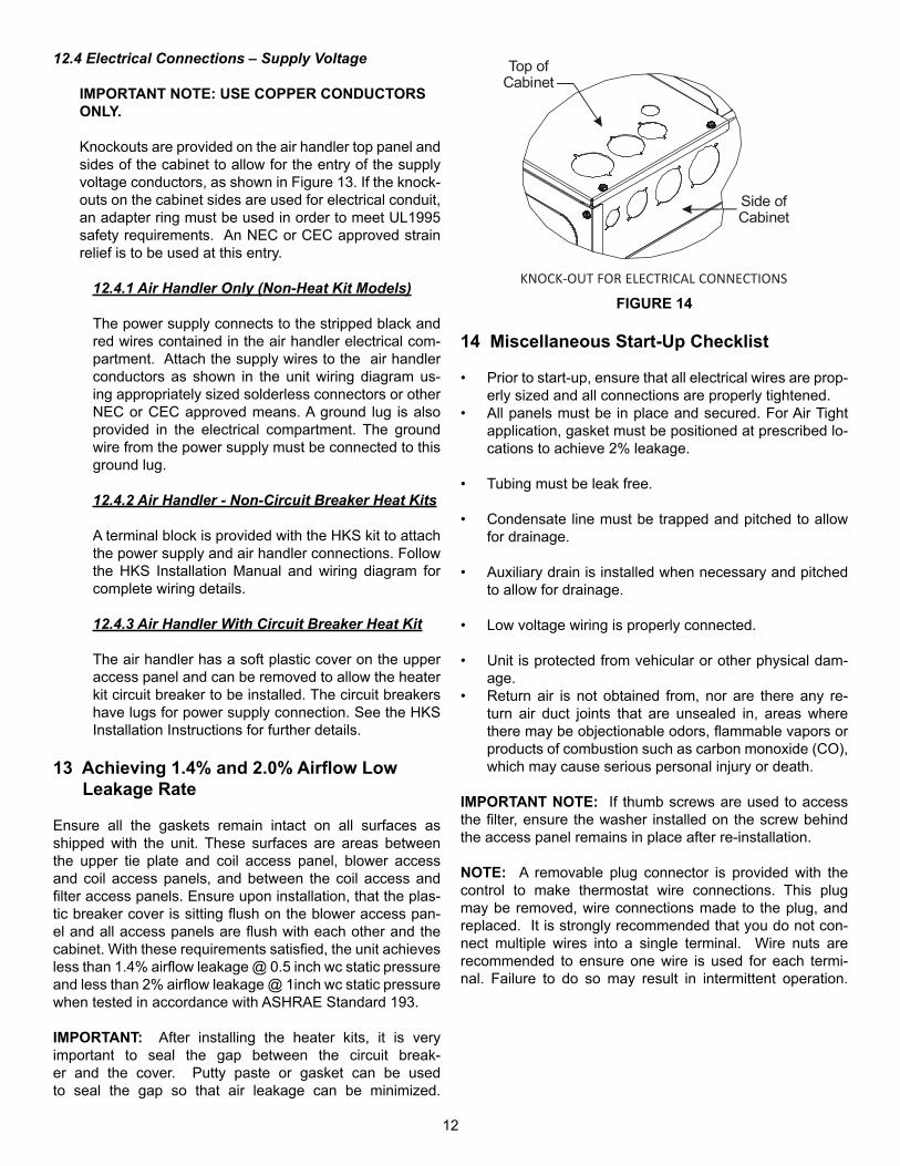
12.4 Electrical Connections – Supply Voltage
IMPORTANT NOTE: USE COPPER CONDUCTORS ONLY.
Knockouts are provided on the air handler top panel and sides of the cabinet to allow for the entry of the supply voltage conductors, as shown in Figure 13. If the knock-outs on the cabinet sides are used for electrical conduit, an adapter ring must be used in order to meet UL1995 safety requirements. An NEC or CEC approved strain relief is to be used at this entry.
12.4.1 Air Handler Only (Non-Heat Kit Models)
The power supply connects to the stripped black and red wires contained in the air handler electrical com-partment. Attach the supply wires to the air handler conductors as shown in the unit wiring diagram us-ing appropriately sized solderless connectors or other NEC or CEC approved means. A ground lug is also provided in the electrical compartment. The ground wire from the power supply must be connected to this ground lug.
12.4.2 Air Handler - Non-Circuit Breaker Heat Kits
A terminal block is provided with the HKS kit to attach the power supply and air handler connections. Follow the HKS Installation Manual and wiring diagram for complete wiring details.
12.4.3 Air Handler With Circuit Breaker Heat Kit
The air handler has a soft plastic cover on the upper access panel and can be removed to allow the heater kit circuit breaker to be installed. The circuit breakers have lugs for power supply connection. See the HKS Installation Instructions for further details.
13 Achieving 1.4% and 2.0% Airflow Low Leakage Rate
Ensure all the gaskets remain intact on all surfaces as shipped with the unit. These surfaces are areas between the upper tie plate and coil access panel, blower access and coil access panels, and between the coil access and filter access panels. Ensure upon installation, that the plas-tic breaker cover is sitting flush on the blower access pan-el and all access panels are flush with each other and the cabinet. With these requirements satisfied, the unit achieves less than 1.4% airflow leakage @ 0.5 inch wc static pressure and less than 2% airflow leakage @ 1inch wc static pressure when tested in accordance with ASHRAE Standard 193.
IMPORTANT: After installing the heater kits, it is very important to seal the gap between the circuit break-er and the cover. Putty paste or gasket can be used to seal the gap so that air leakage can be minimized.
Side ofCabinet
Top ofCabinet
KNOCK-OUT FOR ELECTRICAL CONNECTIONS
FIGURE 14
14 Miscellaneous Start-Up Checklist
• Prior to start-up, ensure that all electrical wires are prop-erly sized and all connections are properly tightened.
• All panels must be in place and secured. For Air Tight application, gasket must be positioned at prescribed lo-cations to achieve 2% leakage.
• Tubing must be leak free.
• Condensate line must be trapped and pitched to allow for drainage.
• Auxiliary drain is installed when necessary and pitched to allow for drainage.
• Low voltage wiring is properly connected.
• Unit is protected from vehicular or other physical dam-age.
• Return air is not obtained from, nor are there any re-turn air duct joints that are unsealed in, areas where there may be objectionable odors, flammable vapors or products of combustion such as carbon monoxide (CO), which may cause serious personal injury or death.
IMPORTANT NOTE: If thumb screws are used to access the filter, ensure the washer installed on the screw behind the access panel remains in place after re-installation.
NOTE: A removable plug connector is provided with the control to make thermostat wire connections. This plug may be removed, wire connections made to the plug, and replaced. It is strongly recommended that you do not con-nect multiple wires into a single terminal. Wire nuts are recommended to ensure one wire is used for each termi-nal. Failure to do so may result in intermittent operation.

13
14.1 Circulator Blower
This air handler is equipped with a variable speed cir-culator blower. This blower provides several automati-cally-adjusted blower speeds. The Specification Sheet applicable to your model provides an airflow table, showing the relationship between airflow (CFM) and ex-ternal static pressure (E.S.P.).
14.2 AVPEC Motor Orientation
If the unit is in the upflow position, there is no need to rotate the motor. If the unit is in the downflow position, loosen motor mount and rotate motor as shown in the AVPEC Motor Orientation Figure 16. Be sure motor is oriented with the female connections on the casing down. If the motor is not oriented with the connections down, water could collect in the motor and may cause premature failure.
15 Troubleshooting
15.1 Electrostatic Discharge (ESD) Precautions
NOTE: Discharge body’s static electricity before touch-ing unit. An electrostatic discharge can adversely affect electrical components.
Use the following precautions during air handler installa-tion and servicing to protect the integrated control mod-ule from damage. By putting the air handler, the control, and the person at the same electrostatic potential, these steps will help avoid exposing the integrated control module to electrostatic discharge. This procedure is ap-plicable to both installed and uninstalled (ungrounded) blowers.
1. Disconnect all power to the blower. Do not touch the integrated control module or any wire connected to the control prior to discharging your body’s electro-static charge to ground.
2. Firmly touch a clean, unpainted, metal surface of the air handler blower near the control. Any tools held in a person’s hand during grounding will be dis-charged.
3. Service integrated control module or connecting wiring following the discharge process in step 2. Use caution not to recharge your body with static electricity; (i.e., do not move or shuffle your feet, do not touch ungrounded objects, etc.). If you come in contact with an ungrounded object, repeat step 2 before touching control or wires
4. Discharge your body to ground before removing a new control from its container. Follow steps 1 through 3 if installing the control on a blower. Return any old or new controls to their containers before touching any ungrounded object.
AVPEC25B14 AVPEC37C14 AVPEC59D14 AVPEC61D14First Valid Heater Kit 3 5 5 5
Second Valid Heater Kit 5 6 6 6Third Valid Heater Kit 6 8 8 8
Fourth Valid Heater Kit 8 10 10 10Fi�h Valid Heater Kit 10 15 15 15Sixth Valid Heater Kit X 19 20 20
Seventh Valid Heater Kit X X X 25
DIP Switch Se�ng MODEL
HEATER KIT OPTIONS
TABLE 8
FEMALE CONNECTIONS
SIDE VIEW
WAR
NINGSOFTW
A RE VER.
TOP
FRONT VIEW
AVPEC MOTOR ORIENTATIONFIGURE 15

14
16 CoolCloud HVAC Phone Application
NOTE: This equipment has been tested and found to com-ply with the limits for a Class B digital device, pursuant to part 15 of the FCC Rules. These limits are designed to pro-vide reasonable protection against harmful interference in a residential installation. This equipment generates, uses and can radiate radio frequency energy and, if not installed and used in accordance with the instructions, may cause harmful interference to radio communications. However, there is no guarantee that interference will not occur in a particular in-stallation. If this equipment does cause harmful interference to radio or television reception, which can be determined by turning the equipment off and on, the user is encouraged to try to correct the interference by one or more of the following measures:
• Reorient or relocate the receiving antenna.• Increase the separation between the equipment and re-
ceiver.• Connect the equipment into an outlet on a circuit differ-
ent from that to which the receiver is connected.• Consult the dealer or an experienced radio/ TV techni-
cian for help.
Actual screens may look different based on the mobile de-vice being used.
FIGURE 16
This air handler is Bluetooth ready and functions with the CoolCloud HVAC phone application designed to improve the contractor’s setup / diagnostic experience. Users can see specific model information, review active diagnostic er-ror codes, observe system menu testing of all operational modes (heat / cool / fan) directly from the phone. The phone application is also capable of directly updating the air han-dler software anytime updates are available. The application will automatically notify the user.
NOTE: The software update may take up to 20 minutes to complete.
17 Quick Start Guide for Communicating Out-door Units
EXTREMELY IMPORTANT: For all cooling calls, the sys-tem only requires a single Y input from the thermostat. For all heating calls (including applications with backup electric heater kits), the system only requires a single W input from the thermostat. Internal algorithms will control all available cooling and heating stages based on these inputs. Any sin-gle-stage 24VAC thermostat can be used. For proper oper-ation, the thermostat must be setup to control a single stage AC outdoor unit and to control single stage electric heat op-eration. The control board does not accommodate an O wire thermostat input (reversing valve signal). If a heat pump is installed, the thermostat should be setup as stated above. Setting the thermostat for the heat pump control or multi-stage control may result in incorrect performance.
1. Connect all necessary thermostat wires to the thermo-stat connector on the air handler control as instructed by the applicable wiring diagrams shown in this section.
2. Connect the 1 & 2 wires between the indoor and outdoor unit for communicating operation.
12
C
RCG
Y
Optional
Optional
Optional
INDOORBOARD TERMINAL
CONNECTIONS
OUTDOORBOARD TERMINAL
CONNECTIONS
12
C
RCG
Y
24 VACThermostat
Communicating Inverter Air Conditioner or Heat PumpFIGURE 17
3. Download the CoolCloud HVAC phone application for charging and to configure / test system.

15
4. Confirm thermostat heating and cooling calls function properly with equipment.
NOTE: When new version of Bluetooth Communication Software and Air Handler Control Software are available, the phone application notifies the user. Software updates are classified as either optional or mandatory and installed by using the phone application. Install all mandatory software updates and optional updates if necessary.
NOTE: If an E11 code exists for the inverter system imme-diately after line voltage is applied (code shown in the Cool-Cloud HVAC phone application or displayed on the inverter control), the System Verification Test needs to be completed before any other operation. See the following procedure.
1. Allow the system to remain Idle for 5 minutes.
2. Turn the system verification test on either by using the phone application, or by entering the menu through the furnace push buttons.
3. Wait for the test to complete.
17.1 Charging
1. Inverter units using the CoolCloud HVAC phone applica- tion or control board push button:
a. Inverter units are charged by setting the menu (Charge Mode) to ON through the furnace control board push buttons or through the CoolCloud HVAC phone application.
b. The system will remain in charge mode (high speed) for 60 minutes before timing out.
c. The installer must manually shut off charge mode once complete
18 Electric Heater Kit Testing
1. Select the electric heat icon after entering the air han-dler menus while using the CoolCloud phone appli-cation.
2. Select any value less than 50% for low stage oper-ation and any value greater than 50% for high stage operation.
3. Confirm thermostat heating and cooling calls function properly for high stage operation.
19 Dehumidification
Dehumidification allows the air handler’s circulator blower to operate at a reduced speed during a combined thermostat call for cooling and a dehumidification call from the ther-mostat or humidistat. This lower blower speed increases dehumidification of the conditioned air as it passes through
the indoor coil. The control board is equipped with a 24 volt dehumidification input (DH) located on the thermostat wiring connector. The terminal can be configured to enable dehu-midification when the input is energized or de-energized. When using an external dehumidistat, connect it between the R and DH terminals. If the humidistat closes on hu-midity rise or the thermostat energizes this terminal when dehumidification is required, set the control board Dehum Logic Menu (dHL) to “HI” using the push buttons or Cool-Cloud HVAC phone application. If the humidistat opens on humidity or the thermostat de-energizes this terminal when dehumidification is required, set the Dehum Logic Menu to “Lo” using the push buttons or CoolCloud HVAC phone ap-plication.
NOTE: Use dehumidification chart in section 29 to properly setup dehumidification based on thermostat selected.
20 Auxiliary Alarm Switch
The control is equipped with a 24VAC Aux Alarm to be used for a condensate switch install (designated by CONDEN-SATE IN/OUT on the control). By default, the connected AUX switch is normally closed and opens when the water level in the evaporator coil base pan reaches an undesir-able level. The control responds by displaying a “EDF” er-ror code and turning off the outdoor condensing unit. If the AUX switch is detected to be in the closed position for 30 seconds, normal operation resumes and the error message is no longer displayed. See Figure 19 for the connection location.
21 Push Buttons
FIGURE 18
The air handler includes three on-board push buttons al-lowing users to navigate indoor and outdoor system menus. The Right and Left buttons allow the user to scroll through the main menus and to then scroll through available options within specific menus. The Center button is used to enter into a main menu and to then permanently select options within those menus. NOTE: After scrolling to the desired option within a menu, that option may be flashing on the 7-segment displays. This indicates the option has not been officially selected. Press-ing the Center button two times will select that option. The first press will stop the flashing. The second will make the selection official and return you to the main menu.

16
DH/ Y2 G RCY W R 12C
RB
J7
J18
J20
U6
K2
K1J4
TB3
TB5
TB6
TB7
TB4
F2U U2
C2
C62 C4D
2
J11
J14
U4
U5
C5
J5
R15
R14
R27
R26
U8
J1 J2
L5
J3
VR1
R25R13
L4
R61
R62
R63
R14
6
TB2TB1J19
D1
C1
FH2FH1F1U
J13
U4
U5
K3L1 C
89
J15
J12
U10
J10
U12
U1
U11U9
J8 J9 J16 J17
U7
M
EEVOR
YLBK
BL
J6
TS TCTHERMISTOR(HEAT EXCHANGER 1,2)
INTEGRATIONTYPE
PRESSURESENSOR
INDOOR UNITPCB
AUX ALARM
FH3 FH4
VR2
C63
PB3
PB2
PB1
L2
COMMUNICATING BOARD
FIGURE 19

17
22 Accessory Control (Humidifiers, Dehumid-ifiers, Ventilators)
If an external humidifier, dehumidifier or ventilator is in-stalled, it may require airflow from the HVAC system to func-tion properly.
1. Make sure the installed 24VAC thermostat is capable of controlling the accessory or accessories.
2. Connect the appropriate accessory control wires to the accessory devices from the thermostat (see ther-mostat manual for connection and setup instructions).
3. If the thermostat is capable of providing a continuous fan call (G signal) during accessory operation, make sure to connect the thermostat G terminal to the G ter-minal on the indoor unit. Setup thermostat to ensure G signal is energized during accessory operation.
FIGURE 20
4. Select the appropriate fan only airflow for the acces-sory using the indoor unit push button menus or the CoolCloud HVAC phone application.
5. Using the thermostat, independently test each acces-sory in addition to the independently testing continu-ous fan mode.
23 Ramping Profiles
The variable-speed circulator offers four different ramping profiles. These profiles may be used to enhance cooling performance and increase comfort level. Select the desired ramping profile using the CoolCloud phone application or the push button menus.
FIGURE 21

18
24 Electric Air Cleaner
The control is equipped with an Accessory Relay and a pair of ¼ inch accessory terminals which is normally open, labeled EAC-IN and EAC-OUT (see accessory contacts graphic). The Accessory Relay is configured to close any-time the blower is running. A closed relay means the two ter-minals will have continuity between them (the control does not energize these contacts). It is recommended to utilize 24VAC with these terminals and limit the current to 1A.
FIGURE 22
DEHUMIDIFICATION TIPS
For effective dehumidification operation:• Ensure “Dehum” is ON through the CoolCloud Phone
Application.
• Verify the cooling airflow profile is set to “Profile D”.
- By default “Dehum” is ON and the cooling airflow profile is set to “Profile D”.
• For additional dehumidification control, airflow settings are field adjustable and can be fine-tuned to a value that is comfortable for the application from a range of +15% to -15%.
25 MAX AIRFLOW TABLE
Model MAX CFM
AVPEC25B14AVPTC29B14AVPTC35B14AVPTC37B14
1200
AVPTC33C14 1300
AVPTC31C14AVPEC37C14AVPTC39C14
1600
AVPTC37D14AVPTC49C14
1800
AVPTC49D14AVPTC59C14
1900
AVPEC59D14AVPEC61D14
2100
NOTE: The System will not provide airflows above the max airflow values.

19
26 AIR HANDLER TROUBLESHOOTING MATRIXSymptoms of Abnormal
Operation
Diagnostic / Status
LED CodesFault Description Possible Causes Corrective Actions
No outdoor unit operations Communication error with outdoor unit
Improper low voltage wiring between the indoor and outdoor unit
Outdoor control board lost power duirng operation
Locate and correct improper low voltage wiring issue
Identify reason outdoor control board lost power during operation
No Air Handler operation Open fuse Short in low voltage wiring
Locate and correct short in low voltage wiring
Replace fuse with 3-amp automotive type
No Air Handler operationAuxilary switch (condensate switch) open
High water level in the evaporation coil
Check evaporator drain pan, trap, piping
No Air Handler operation Data not yet on network No network data Populate shared data set using memory card
No Air Handler operation Invalid memory card dataAir Handler blower does not contain an appropriate shared data set
Populate correct shared data using memory card
Operation different than expected or no operation Invalid memory card data
Shared data set on memory card has been rejected by integrated control module
Verify shared data set is correct for the specifc model. Re-populate data using correct memory card if required
No Air Handler operationCirculator blower motor not running with demand present
Loose or disconnected wiring connection at circulator motor power leads
Open circuit in inductor or loose wiring connection at inductor (3/4 Hp and 1 Hp models only)
Failed circulator blower motor
Tighten or correct wiring connection
Verify continuous circuit through inductor.
Replace if open or short circuit
Check circulator blower motor
No Air Handler operation
Integrated control module has lost communications with circulator blower motor
Loose wiring connection at circulator motor control leads
Failed circulator blower motor
Failed integrated control module
Tighten or correct wiring connection
Check circulator blower motor, replace if necessary
Check integrated control module, replace if necessary
No Air Handler operation
Circulator blower motor horse power in shared data set does not match circulator blower motor horse power
Incorrect circulator blower motor in Air Handler
Incorrect shared data set in integrated control module
Verify circulator blower if motor horse power is the same specifed for the specifc Air Handler model, replace if necessary
Verify shared data set is correct for the specifc model, re-populate data using correct memory card if required
Air Handler operates at reduced performance
Airfow delivered is less than expected
Circulator blower motor is operating in a power, temperature, or speed limiting condition
Blocked flters
Restrictive or undersized ductwork
High ambient temperatures
Check filters for blockage, clean flters or remove obstruction
Check ductwork for blockage, remove obstruction and verify all registers are fully open
Verify ductwork is appropriately sized for system and resize/replace ass needed
20
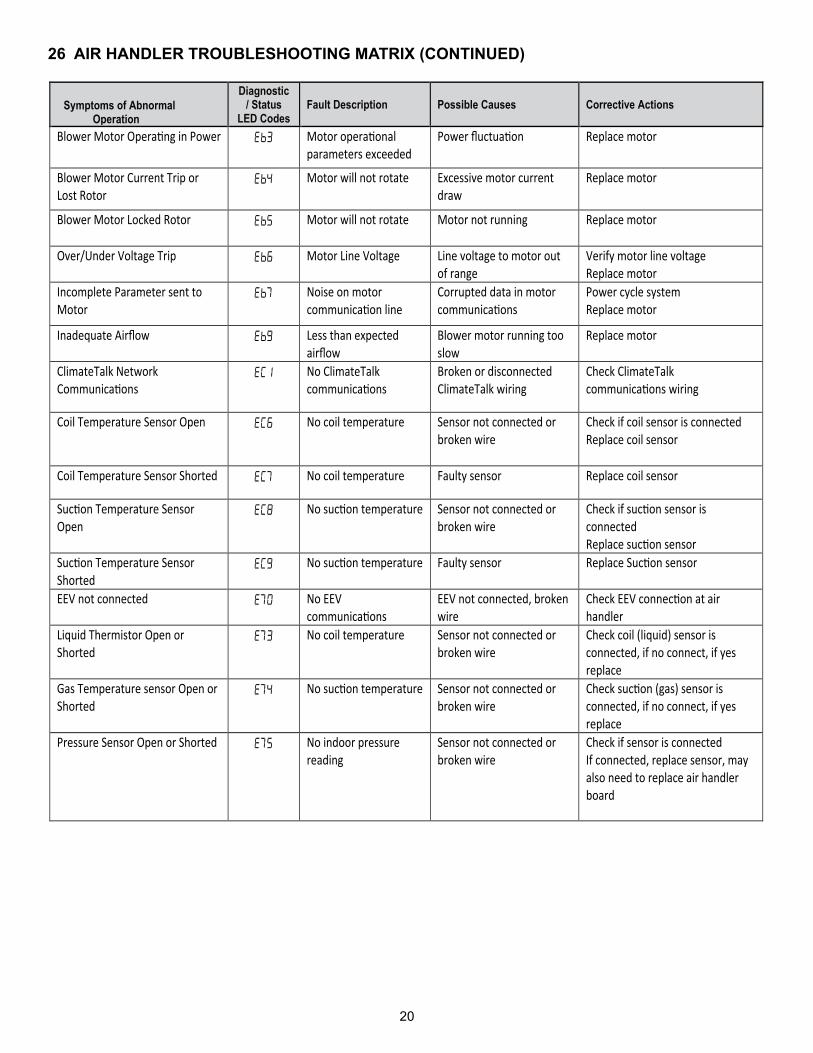
26 AIR HANDLER TROUBLESHOOTING MATRIX (CONTINUED)
Symptoms of Abnormal Operation
Diagnostic / Status
LED Codes Fault Description Possible Causes Corrective Actions
Blower Motor Opera�ng in Power Motor opera�onal parameters exceeded
Power fluctua�on
Replace motor
Blower Motor Current Trip or Lost Rotor
Motor will not rotate Excessive motor current draw
Replace motor
Blower Motor Locked Rotor Motor will not rotate Motor not running Replace motor
Over/Under Voltage Trip Motor Line Voltage Line voltage to motor out of range
Verify motor line voltage Replace motor
Incomplete Parameter sent to Motor
Noise on motor communica�on line
Corrupted data in motor communica�ons
Power cycle system Replace motor
Inadequate Airflow Less than expected airflow
Blower motor running too slow
Replace motor
ClimateTalk Network Communica�ons
No ClimateTalk communica�ons
Broken or disconnected ClimateTalk wiring
Check ClimateTalk communica�ons wiring
Coil Temperature Sensor Open No coil temperature Sensor not connected or broken wire
Check if coil sensor is connected Replace coil sensor
Coil Temperature Sensor Shorted No coil temperature Faulty sensor Replace coil sensor
Suc�on Temperature Sensor Open
No suc�on temperature Sensor not connected or broken wire
Check if suc�on sensor is connected Replace suc�on sensor
Suc�on Temperature Sensor Shorted
No suc�on temperature Faulty sensor Replace Suc�on sensor
EEV not connected No EEV communica�ons
EEV not connected, broken wire
Check EEV connec�on at air handler
Liquid Thermistor Open or Shorted
No coil temperature Sensor not connected or broken wire
Check coil (liquid) sensor is connected, if no connect, if yes replace
Gas Temperature sensor Open or Shorted
No suc�on temperature Sensor not connected or broken wire
Check suc�on (gas) sensor is connected, if no connect, if yes replace
Pressure Sensor Open or Shorted No indoor pressure reading
Sensor not connected or broken wire
Check if sensor is connected If connected, replace sensor, may also need to replace air handler board
21
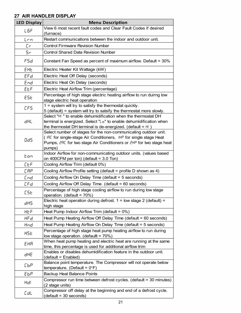
27 AIR HANDLER DISPLAYLED Display Menu Descrip�on
View 6 most recent fault codes and Clear Fault Codes if desired (furnace)Restart communications between the indoor and outdoor unit. Control Firmware Revision NumberControl Shared Data Revision Number
Constant Fan Speed as percent of maximum airflow. Default = 30%
Electric Heater Kit Wattage (kW)Electric Heat Off Delay (seconds)Electric Heat On Delay (seconds)Electric Heat Airflow Trim (percentage)Percentage of high stage electric heating airflow to run duirng low stage electric heat operation 1 = system will try to satisfy the thermostat quickly. 5 (default) = system will try to satsify the thermostat more slowly.Select " " to enable dehumidification when the thermostat DH terminal is energized. Select " " to enable dehumidification when the thermostat DH terminal is de-energized. (default = )Select number of stages for the non-communicating outdoor unit. ( for single-stage Air Conditioners, for single stage Heat Pumps, for two stage Air Conditioners or for two stage heat pumps)Indoor Airflow for non-communicating outdoor units. (values based on 400CFM per ton) (default = 3.0 Ton)Cooling Airflow Trim (default 0%)Cooling Airflow Profile setting (default = profile D shown as 4)Cooling Airflow On Delay Time (default = 5 seconds)Cooling Airflow Off Delay Time. (default = 60 seconds)Percentage of high stage cooling airflow to run during low stage operation. (default = 70%)Electric heat operation during defrost. 1 = low stage 2 (default) = high stageHeat Pump Indoor Airflow Trim (default = 0%)Heat Pump Heating Airflow Off Delay Time (default = 60 seconds)Heat Pump Heating Airflow On Delay Time (default = 5 seconds)Percentage of high stage heat pump heating airflow to run during low stage operation. (defaullt = 70%)When heat pump heating and electric heat are running at the same time, this percentage is used for additional airflow trimEnables or disables dehumidification feature in the outdoor unit. (default = Enabled)Balance point temperature. The Compressor will not operate below temperature. (Default = 0 F)Backup Heat Balance PointsCompressor run time between defrost cycles. (default = 30 minutes) (2 stage units)Compressor off delay at the beginning and end of a defrost cycle. (default = 30 seconds)

22
27 AIR HANDLER DISPLAY (CONTINUED)
LED Display Menu Descrip�onView 6 most recent fault codes and Clear Fault Codes if desired (outdoor communicating units)Menu is enabled if the menu is set to 6. Select the target time the system will attempt to satisfy the thermostat.Menu is enabled if the menu is set to 6. Select the percentage past the target time when the system will enable electric heat operation during heat mode. Menu is enabled if the is set to 6. (Electric heat will run during the next heat call if the heat pump fails to satisfy the custom target time for this number of consecutive cycles) (default = 20 cycles)Menu is enabled if the menu is set to 6. (if the addition of low stage electric heat is able to consecutively satisfy the thermostat under the set target time for this number of cycles, the system will transition to the heat pump for primary heating)Menu is enabled if the menu is set to 6. (this percentage will help determine when switching back to heat pump only operation is appropriate. Default = 20%. If target time = 20 minutes, the addtion of low stage electric heat must staisfy the thermostat by less than 16 minutes. (target time - 20% default = 16 minutes).

23
27 AIR HANDLER DISPLAY (CONTINUED)
LED Display Descrip�on of System StatusIdleConstant FanCompressor Cooling, Single-Stage (non-comm. units)Compressor Cooling, Low Stage (non-comm units)Compressor Cooling, High Stage (non-comm units)Compressor Cooling, Low Stage (comm units)Compressor Cooling, High Stage (comm units)Compressor Heat, Single-Stage (non-comm. units)Compressor Heat, Low Stage (non-comm Units)Compressor Heat, High Stage (non-comm Units)Compressor Heat, Low Stage (Comm Units)Compressor Heat, High Stage (Comm Units)Electric Heat, Single StageElectric Heat, Low StageElectric Heat, High StageDefrost, Single Stage Electric HeatDefrost, Low Stage Electric HeatDefrost, High Stage Electric HeatDehumidification

24
28 WIRING DIAGRAM
HIGH VOLTAGE! DISCONNECT ALL POWER BEFORESERVICING. MULTIPLE POWER SOURCES MAY BEPRESENT. FAILURE TO DO SO MAY CAUSE PROPERTYDAMAGE, PERSONAL INJURY OR DEATH.
NOTE: THESE INSTRUCTIONS ARE SPECIFICALLY FOR AVPECMODELS. DO NOT ATTEMPT TO APPLY THESE DIAGRAMS FOR ANYOTHER MODELS.
0140A00723-A
HEATER KITOUTPUT
43 65 987 10 11 12
BKRD
BKRD
BL
BR
WH
BL RDPU YL
RD BK
GROUND LUG(SEE NOTE 4)
24VAC
TB5
TB4
INSTALLINGAUX ALARM(ALARM)(SEE NOTE 9) ~~
~~
~~
24VAC
MOCMOC208VAC
230VAC
208VAC 230
VAC
TR2(SEE NOTE 1)
TR1(SEE NOTE 1)
FANMOTOR
21BKRD GY BL
ECM MOTOR
BKRD
PL1
PL29 78 456 3 2 1
PL3
PL4
INTEGRATED CONTROL:
POWER/HEATERCONNECTOR
PL1, PL2
COMPONENT CODES:
TL
F1U, F2UTR
THERMAL LIMITTRANSFORMERFUSE LINK
NOTES:1. PLACE RED WIRES ON 208 V TERMINAL OF 2-TRANSFORMER (TR1/TR2) FOR 208 VAC OPERATION.
2. MANUFACTURER’S SPECIFIED REPLACEMENT PARTS MUST BE USED WHEN SERVICING.
3. IF ANY OF THE ORIGINAL WIRES AS SUPPLIED WITH THIS UNIT MUST BE REPLACED, IT MUST BE REPLACED WITH WIRING MATERIAL HAVING A
C. USE COPPER CONDUCTORS ONLY.
4. UNIT MUST BE PERMANENTLY GROUNDED AND CONFORM TO N.E.C ANDLOCAL CODES.
5. TO RECALL THE LAST 6 FAULTS, MOST RECENT TO LEAST RECENT, DEPRESS FAULT RECALL BUTTON FOR MORE THAN 2 SECONDS WHILE IN STANDBY (NO THERMOSTAT INPUTS)
6. YELLOW STATUS LED PROVIDES NETWORK STATUS.GREEN RX LED INDICATES NETWORK TRAFFIC
7. DISCARD CONNECTOR PL1 WHEN INSTALLING OPTIONAL HEAT KIT.
8. REMOVE SHORT RED CIRCUITING WIRE AND PUT AUX ALARM SWITCH WHEN INSTALLING AUX ALARM SWITCH.
9. USE N.E.C CLASS 2 WIRE.
COLOR CODES:
BL - BLUE
RD - RED
YL - YELLOW
OR - ORANGE
BK - BLACK
GY - GREY
BR - BROWN
GR - GREEN
PU - PURPLE
WH - WHITE
LOW VOLTAGE
LOW VOLTAGE FIELD
HIGH VOLTAGE
HIGH VOLTAGE FIELD
JUNCTION
TERMINAL
INTERNAL TO
RESISTOR
OVERCURRENTPROT. DEVICE
PLUG CONNECTION
EQUIPMENT GND
FIELD GROUND
THERMISTOR(HEAT EXCHANGER 1,2)
MBK
INDOOR UNITPCB
THERMISTOR(HEAT EXCHANGER 1,2)
PRESSURESENSOR
EEVCOIL
EEV
MINTEGRATION
RD YLOR
BL
AUX ALARM(ALARM)AUX ALARM(ALARM)
GR
(SEE NOTE 7)
GY BK
THERMOSTAT
RD BK
BK RD
208/230VACTO
HEATER KIT
TRANSFORMERCONNECTOR
PL3, PL4
BL
GRND
AIR
COM
W
C
208/230 VAC
CONDENSATE SWITCH
INDOOR
L1
HEAT 1 COIL/R1
TR2
INTEGRATED CONTROL MODULE
CIRCULATOR
+VDC (1)
GRND
BLWR
BLWR
EH2
L2
40 VA
R
TOMICRO
TH2
CIRCULATOR
L1
INDOOR
DEHUMGRND (4)
RX (2)
24 VAC
AIR
AUX IN
FUSE 3 A
GRND
TX (3)
G
EH1
AUX OUT
TRANSFORMER
DISCONNECT
HEAT 2 COIL/ R2
L2
TYPE
RD
J6 J7 J18
TH1 TR1
Y
J19 TB1 TB2
FH1 FH2F1U VR1
C1
D1
C2
D2TB
7TB
4
TB3
TB5
TB6
FH3F2U
FH4
VR
2
C63
U2
K3
K1
K2
U6
J6 J7
J20
PB1
PB2
PB3
J8 J9 J16 J17 J18
U9
J4
U1
J10
B11
B12
U4
U10
C89
J14
J11
U5
U3 L2
L1
J13
J15
J12
U7
+ _~~
U8
C5
R14
6
C4C62
R63
R62
R61 L4
J1 J2
L5
J5
J3
R13 R25
R15
R14
R27
R26
RCGWYDH/Y2 RC 21
25
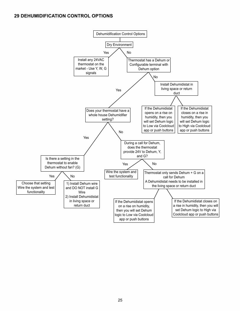
29 DEHUMIDIFICATION CONTROL OPTIONS
1) Install Dehum wire and DO NOT install G
Wire 2) Install Dehumidistat
in living space or return duct
Is there a setting in the thermostat to enable
Dehum without fan? (G)
YesNo
During a call for Dehum, does the thermostat
provide 24V to Dehum, Y, and G?
Yes No
Choose that settingWire the system and test
functionality
Yes No
Wire the system and test functionality
Dehumidification Control Options
Dry Environment
Yes No
Install any 24VAC thermostat on the
market - Use Y, W, G signals
Thermostat has a Dehum or Configurable terminal with
Dehum option
Yes
No
Does your thermostat have a whole house Dehumidifier
setting?
Install Dehumidistat in living space or return
duct
If the Dehumidistat opens on a rise on humidity, then you
will set Dehum logic to Low via Coolcloud app or push buttons
If the Dehumidistat closes on a rise in humidity, then you
will set Dehum logic to High via Coolcloud app or push buttons
Thermostat only sends Dehum + G on a call for Dehum
A Dehumidistat needs to be installed in the living space or return duct
If the Dehumidistat opens on a rise on humidity,
then you will set Dehum logic to Low via Coolcloud
app or push buttons
If the Dehumidistat closes on a rise in humidity, then you will
set Dehum logic to High via Coolcloud app or push buttons

26
AIR HANDLER HOMEOWNER’S ROUTINE MAINTENANCE RECOMMENDATIONS
We strongly recommend a bi-annual maintenance checkup be performed before the heating and cooling seansons be-gin by a qualified servicer.
REPLACE OR CLEAN FILTER
IMPORTANT NOTE: Never operate unit without a filter in-stalled as dust and lint will build up on internal parts resulting in loss of efficiency, equipment damage and possible fire. An indoor air filter must be used with your comfort system. A properly maintained filter will keep the indoor coil of your comfort system clean. A dirty coil could cause poor opera-tion and/or severe equipment damage.
Your air filter or filters could be located in your furnace, in a blower unit, or in “filter grilles” in your ceiling or walls. The installer of your air conditioner or heat pump can tell you where your filter(s) are, and how to clean or replace them.
Check your filter(s) at least once a month. When they are dirty, replace or clean as required. Disposable type filters should be replaced. Reusable type filters may be cleaned.
You may want to ask your dealer about high efficiency fil-ters. High efficiency filters are available in both electronic and non-electronic types. These filters can do a better job of catching small airborne particles.
MOTORS
Indoor and outdoor fan motors are permanently lubricated and do not require additional oiling.
WARNING
HIGH VOLTAGE!DISCONNECT ALL POWER BEFORE SERVICING OR INSTALLING THIS UNIT. MULTIPLE POWER SOURCES MAY BE PRESENT. FAILURE TO DO SO MAY CAUSE PROPERTY DAMAGE, PERSONAL INJURY OR DEATH.
ALUMINUM INDOOR COIL CLEANING(QUALIFIED SERVICER ONLY)This unit is equipped with an aluminum tube evaporator coil. The safest way to clean the evaporator coil is to simply flush the coil with water. This cleaning practice remains as the recommended cleaning method for both copper tube and aluminum tube residential evaporator coils.
It has been determined that many coil cleaners and drain pan tablets contain corrosive chemicals that can be harm-ful to aluminum tube and fin evaporator coils. Even a one-time application of these corrosive chemicals can cause premature aluminum evaporator coil failure. Any cleaners that contain corrosive chemicals including, but not limitedto, chlorine and hydroxides, should not be used.
An alternate cleaning method is to use one of the products listed in TP-109* to clean the coils. The cleaners listed are the only agents deemed safe and approved for use to clean round tube aluminum coils. TP-109 is also available on the web site in Partner Link > Service Toolkit.
NOTE: Ensure coils are rinsed well after use of any chemi-cal cleaners.
BEFORE YOU CALL YOUR SERVICER
CAUTION
TO AVOID THE RISK OF EQUIPMENT DAMAGE OR FIRE, INSTALL THE SAME AMPERAGE BREAKER OR FUSE AS YOU ARE RE-PLACING. IF THE CIRCUIT BREAKER OR FUSE SHOULD OPEN AGAIN WITHIN THIRTY DAYS, CONTACT A QUALIFIED SERVICER TO CORRECT THE PROBLEM. IF YOU REPEATEDLY RESET THE BREAKER OR REPLACE THE FUSE WITHOUT HAVING THE PROBLEM CORRECTED, YOU RUN THE RISK OF SEVERE EQUIPMENT DAMAGE.
• Check the thermostat to confirm that it is properly set.
• Wait 15 minutes. Some devices in the outdoor unit or in programmable thermostats will prevent compressor operation for awhile, and then reset automatically. Also, some power companies will install devices which shut off air conditioners for several minutes on hot days. If you wait several minutes, the unit may begin operation on its own.
• Check the electrical panel for tripped circuit breakers or failed fuses. Reset the circuit breakers or replace fuses as necessary.
• Check the disconnect switch near the indoor furnace or blower to confirm that it is closed.
• Check for obstructions on the outdoor unit . Confirm that it has not been covered on the sides or the top. Remove any obstruction that can be safely removed. If the unit is covered with dirt or debris, call a qualified servicer to clean it.
• Check for blockage of the indoor air inlets and outlets. Confirm that they are open and have not been blocked by objects (rugs, curtains or furniture).
• Check the filter. If it is dirty, clean or replace it.
• Listen for any unusual noise(s), other than normal oper-ating noise, that might be coming from the outdoor unit. If you hear unusual noise(s) coming from the unit, call a qualified servicer.

27
THIS PAGE WAS LEFT BLANK INTENTIONALLY

28
CUSTOMER FEEDBACKWe are very interested in all product comments.
Goodman® Brand Products: .Amana® Brand Products: .You can also scan the QR code on the right for the product brandyou purchased to be directed to the feedback page.
GOODMAN® BRAND AMANA® BRAND
GOODMAN® BRAND AMANA® BRAND
PRODUCT REGISTRATION
Quebec residents to register their product does not diminish their warranty rights.
Goodman® Brand products: .Amana® Brand products: You can also scan the QR code on the right for the product brand