Embed Size (px)
Citation preview

V1.0
INSTALLATION & TROUBLESHOOTING GUIDE
AvMeshTM
RF Communications Systems

2
Version No. Description Date Author Reviewed Approved Design1.0 Manual Launch April 2019 P. Naidu J. Ohle W. Evans M. Sugars

AvMesh® RF Communications SystemsInstallation & Service Manual
Latest products and information available at www.avlite.com 3
Table of Contents1.0 Glossary of Terms .......................................................................................................................52.0 Background ..................................................................................................................................63.0 RF Fundamentals ........................................................................................................................ 7 3.1 Elements of a Radio Frequency communications system ........................................................................7 3.2 Modulation and Demodulation .................................................................................................................................. 8 3.3 Intermodulation .................................................................................................................................................................. 8 3.4 Antennas ................................................................................................................................................................................ 9 3.4.1 Gain................................................................................................................................................................................10 3.4.2 Direction ......................................................................................................................................................................10 3.4.3 Polarization ................................................................................................................................................................. 11 3.5 RF Propagation ................................................................................................................................................................... 11 3.5.1 Line-of-sight propagation .................................................................................................................................. 12 3.6 Interference .........................................................................................................................................................................13 3.6.1 Fresnel zones ............................................................................................................................................................13 3.6.2 In-band interference ............................................................................................................................................15 3.7 Spectrum Analyzers .......................................................................................................................................................16 3.7.1 Types of Spectrum Analyzer ...........................................................................................................................16 3.7.2 The Decibel formula ............................................................................................................................................. 17 3.7.3 Signal to Noise Ratio (SNR or S/N) ...............................................................................................................194.0 AvMeshTM Communications System: Theory of Operation ...............................................20 4.1 Node Information ............................................................................................................................................................. 20 4.2 Network set-up procedure .........................................................................................................................................21 4.3 Network bridging ............................................................................................................................................................245.0 Avlite Wireless Remote Controller......................................................................................... 27 5.1 Radio Controller Menu ................................................................................................................................................... 27 5.1.1 Operation Mode ....................................................................................................................................................... 27 5.1.2 Advanced Op Mode .............................................................................................................................................28 5.1.3 Light Group ...............................................................................................................................................................28 5.1.4 Intensity .......................................................................................................................................................................28 5.1.5 Timeout Mode .........................................................................................................................................................28 5.1.6 Timeout Duration ...................................................................................................................................................29 5.1.7 Diagnostic ...................................................................................................................................................................29 5.2 Controller Menu (Advanced) .................................................................................................................................... 306.0 Direct Connection ...................................................................................................................... 31 6.1 To force a primary node ...............................................................................................................................................317.0 Rotary Switches ........................................................................................................................32 7.1 To force a Reserve node...............................................................................................................................................328.0 Maintenance/Housekeeping of the AvMeshTM Communications System ......................329.0 Troubleshooting ........................................................................................................................33 9.1 Identifying the Problem.................................................................................................................................................33 9.2 Single Fixture Non-functional ...................................................................................................................................34 9.3 Whole Runway Non-functional ...............................................................................................................................35 9.4 Multiple Fixtures Non-functional .............................................................................................................................36 9.4 Multiple Fixtures Non-functional Continued ....................................................................................................37

4
Table of FigureFigure 1: Hub and Spoke architecture (left) and Mesh Network (right) ..................................6
Figure 2: Radio Communications System .................................................................................................7
Figure 3: Wavelength is inversely proportional to frequency .......................................................7
Figure 4: Creation of intermodulation products ................................................................................... 9
Figure 5: Radiation pattern of Isotropic (left) and Dipole (right) antennas ..........................10
Figure 6: Unidirectional (left), Bi-directional (center) and Omnidirectional (right) antennas ......................................................................................................................................................................10
Figure 7: Vertically (left) and Horizontally (right) polarized antennas ...................................... 11
Figure 8: The first (red), second (green) and third (blue) Fresnel zones between the transmitting and receiving antennas ......................................................................................................... 14
Figure 9: The first node to turn on will become a primary node ............................................. 21
Figure 10: The nodes are configured as primary if they are not within range of at least 3 other primary nodes ........................................................................................................................... 22
Figure 11: If the node is within range of at least 3 other primary nodes, it will become a reserve node .................................................................................................................................... 22
Figure 12: If a node is within range of at least 3 other primary and 3 other reserve nodes, it will remain as a listen only node .............................................................................................. 23
Figure 13: Resulting mesh network .......................................................................................................... 23
Figure 14: Creation of 2 different network IDs, one at each end of the runway ............ 24
Figure 15: The next nodes to turn on will be independent of the nodes at the other end of the runway ................................................................................................................................................ 25
Figure 16: Node 5 will become a primary node in network 4 if node 9 accepts the bridging ....................................................................................................................................................................... 25
Figure 17: Other primary nodes within range of node 5 will also join the new network ....................................................................................................................................................................... 26
Figure 18: All primary nodes will adopt the better network ....................................................... 26

AvMesh® RF Communications SystemsInstallation & Service Manual
Latest products and information available at www.avlite.com 5
1.0 Glossary of TermsAttenuation - The negative ratio of the output power to the input power in decibels (dB). It is the reduction in power of a signal as it propagates through space.
Carrier signal - a pure wave of constant frequency, amplitude and phase.
Centre frequency - The central frequency of a filter or channel, centered between the upper and lower cutoff frequencies.
Fresnel Zone - A theoretical elliptical region between the transmitting and receiving antennas. The size of the ellipse is determined by the frequency of operation and the distance between the transmitter and receiver. If 80% of the first Fresnel Zone is free of obstacles, the propagation loss is said to be equivalent to free space loss.
Gain - The positive ratio of the output power to the input power in decibels (dB).
Interference - Any external factor (such as physical obstacles, noise or other radio signals) that degrade or reduce the clarity of the desired radio signal.
Light group - A way to group lights in an area so that they can be controlled in unison. This allows the airfield to independently control different areas such as multiple run-ways, taxiways and helipads.
Listen only light - A light that will receive commands and act upon them, but will not pass the commands on.
Mesh network - A local network architecture in which the nodes connect to as many nodes as possible and cooperate with one another to transfer data from point to point.
Noise floor - This is the measure of signal created from noise sources and unwanted signals, with noise defined as a signal other than that being monitored. It may include atmospheric noise, thermal noise and cosmic noise.
Passband - The range of frequencies that can pass through a filter without attenuation.
Primary Node - A light that is part of the primary AvMeshTM network. This light will receive commands from a controller, other primary node or a reserve node. This light will act upon the commands and pass them on to other nodes in the network.
Reference level - The top most line in the spectrum analyzer display.
Reserve node - A light that is part of the reserve AvMeshTM network. This light will receive commands from a controller, a primary node or another reserve node. This light will act upon the commands and pass them on to other nodes in the network.
RF Propagation - The behavior in which radio waves travel from one point to another.
Sensitivity - The smallest signal that can be detected by the receiver.
Selectivity - The ability of a receiver to differentiate between signals that are close together in frequency.
Span - The range between the measured start and stop frequencies.
Spectrum analyzer - An electronic measurement device that helps to determine the type and frequencies of interfering RF signals.
Transmit Power - The power that is input to the antenna cable, before cable loss and antenna gain are considered.
6
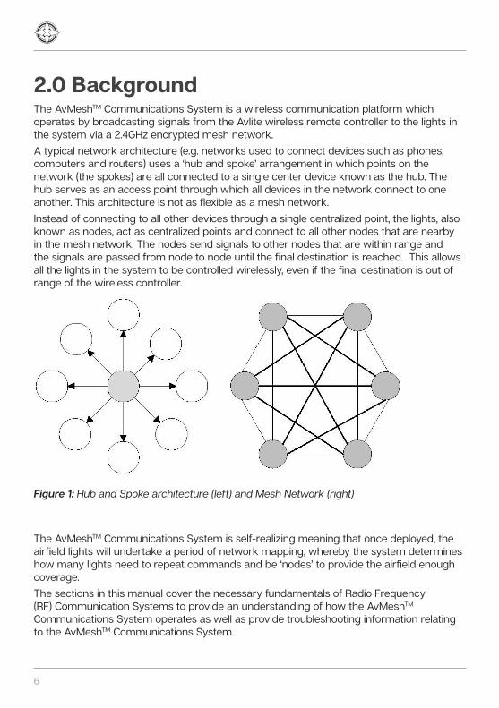
2.0 BackgroundThe AvMeshTM Communications System is a wireless communication platform which operates by broadcasting signals from the Avlite wireless remote controller to the lights in the system via a 2.4GHz encrypted mesh network. A typical network architecture (e.g. networks used to connect devices such as phones, computers and routers) uses a ‘hub and spoke’ arrangement in which points on the network (the spokes) are all connected to a single center device known as the hub. The hub serves as an access point through which all devices in the network connect to one another. This architecture is not as flexible as a mesh network. Instead of connecting to all other devices through a single centralized point, the lights, also known as nodes, act as centralized points and connect to all other nodes that are nearby in the mesh network. The nodes send signals to other nodes that are within range and the signals are passed from node to node until the final destination is reached. This allows all the lights in the system to be controlled wirelessly, even if the final destination is out of range of the wireless controller.
Figure 1: Hub and Spoke architecture (left) and Mesh Network (right)
The AvMeshTM Communications System is self-realizing meaning that once deployed, the airfield lights will undertake a period of network mapping, whereby the system determines how many lights need to repeat commands and be ‘nodes’ to provide the airfield enough coverage. The sections in this manual cover the necessary fundamentals of Radio Frequency (RF) Communication Systems to provide an understanding of how the AvMeshTM Communications System operates as well as provide troubleshooting information relating to the AvMeshTM Communications System.

AvMesh® RF Communications SystemsInstallation & Service Manual
Latest products and information available at www.avlite.com 7
3.0 RF Fundamentals3.1 Elements of a Radio Frequency communications system
A typical radio frequency communication system consists of the following elements: • Transmitter - Feeds the signal to a transmitting antenna by first encoding the data
into RF waves (signals) with a certain signal strength (known as the power output) to project the signal to the receiver.
• Receiver - Accepts and decodes the RF signals that come through the receiving antenna and rejects unwanted ones via the use of a filter.
• Environment - The physical space between the transmitter and receiver over which the radio waves propagate. The environment through which communication is occurring can be affected by interference and physical obstructions such as walls, buildings and vegetation.
• Antennas or other focusing elements - Devices that focus the radio frequency energy in a particular direction.
Figure 2: Radio Communications System
In radio frequency communication, electromagnetic waves (signals) are created and radiated from a source (i.e. transmitting antenna at the transmitter) and then travel through the air at the speed of light after which they are picked up at a particular destination (i.e. receiving antenna at the receiver). The higher the frequency of an electromagnetic wave (signal), the shorter the wavelength. Signals with longer wavelengths are typically able to travel a greater distance and bend around objects better than signals with shorter wavelengths.
Figure 3: Wavelength is inversely proportional to frequency
Transmitter ReceiverTransmitter Receiver
Transmitting Antenna
Receiving Antenna
Environment
Transmitter Receiver
Transmitting Antenna
Receiving Antenna
Environment
Lower frequency-longer wavelengthLower frequency-longer wavelength
Higher frequency-shorter wavelengthHigher frequency-
shorter wavelengthHigher frequency-
shorter wavelength Lower frequency-longer wavelengthLower frequency-longer wavelength
Higher frequency-shorter wavelengthHigher frequency-
shorter wavelengthHigher frequency-
shorter wavelength

8
3.2 Modulation and Demodulation
Modulation occurs in the transmitter, where the input signal (also known as the modulating signal) is intentionally ‘mixed’ with a sinusoidal carrier wave (a wave of constant frequency, amplitude and phase). Through this process, one of the three parameters (i.e. amplitude, frequency or phase) of the carrier wave is modified by the input signal according to a predefined method known as the modulation technique. This encodes the carrier wave with the required information from the input signal before the carrier wave is transmitted to the receiver. The information contained in the input signal is able to travel over a much larger distance when encoded into the carrier wave. After the modulated carrier wave is received and amplified by the receiver, the transmitted information is extracted from the carrier wave through a process known as demodulation. The type of demodulation used to remove the carrier wave depends on the technique used during modulation. It is important to note that the receiver must be able to identify the received modulated carrier signal from other signals which may be using the same channel.
For a two-signal input into a modulator (or non-linear mixer or amplifier), an input signal of frequency f1 is mixed with a carrier signal (or other competing signal) of frequency f2. These signals will be present at the output along with additional signals called intermodulation products which are at the sum and difference and integer multiples of the original frequencies. The frequencies of the intermodulation products can range in order from second order (e.g. 2f1, 2f2, f1-f2 or f1+f2), third order (e.g. 3f1, 3f2, 2f1-f2, 2f1+f2, 2f2-f1, 2f2+f1), fourth order (e.g. 4f1, 4f2, 2f2+2f1,2f2-2f1,2f1+2f2, 2f1-2f2) up to the nth order and usually arise from non-linearity in the signal processing equipment. When many transmitters are placed at the same location, intermodulation may become an issue. Typically, it is the third odd order intermodulation products which are of most concern because they are the closest in frequency to the fundamental frequencies and therefore cannot be effectively filtered out of the system (although this is not limited to only third order products). This results in a spectrum of products that are spread out either side of the fundamental frequencies which increases the bandwidth of the signal. In some cases, the bandwidth of the signal is increased to a degree where it causes sideband splatter in which the channels either side of the operating frequency are impinged by the wider bandwidth of the signal. This causes interference with other systems operating in these directly adjacent channels, otherwise known as co-channel interference.
3.3 Intermodulation

AvMesh® RF Communications SystemsInstallation & Service Manual
Latest products and information available at www.avlite.com 9
Figure 4: Creation of intermodulation products
Furthermore, the third order intermodulation products can potentially pass through the receiver since they are close in frequency to the fundamental frequencies. Consider the situation in which 3 signals are present at the input of a non-linear amplifier or mixer; one is the signal of interest at frequency f3 (e.g. 140 MHz) and the other two are competing signals at frequencies f1 (e.g. 100MHz) and f2 (e.g. 120MHz). There are 15 combinations of third order intermodulation products (including harmonics) from the interactions between the signal of interest (f3) and the competing signals (f1 and f2). One of these intermodulation products (i.e. 2f2-f1=2x120 – 100=140MHz) is equal to the frequency of the signal of interest (f3) and as a result, this intermodulation product will enter the receiver and interfere with the signal of interest. As a consequence, the receiver is at risk of extracting and processing the incorrect information. It is therefore essential to calculate the 3rd order harmonics and intermodulation products for all combinations of competing frequencies in a site to determine if there is a possibility of interference.
Antennas are a key component of any radio frequency communications system as they enable the transfer of information from the transmitter to the receiver. For this reason, poor antenna performance limits the performance of the overall system. Antennas provide a radio communication system with three main properties; gain, direction and polarization. A description of each is given in the following sections.
Typically, antennas do not transmit or receive radio frequency energy uniformly in all directions and instead, transmit or receive more in some directions compared to others. The antenna gain can be defined as a ratio of the highest signal strength transmitted or received in a particular direction to that of a reference antenna. The two main types of reference antenna are either the isotropic antenna which radiates the radio frequency energy uniformly in all directions or the dipole which does not.
f1-f
2f1 f2
Frequency
Am
plit
ude 2f1-
f2
2f2-
f1
2f1
f1+f
22f
2
3f1
2f1+
f2f1
+2f2
3f2
f1-f
2f1 f2
Frequency
Am
plit
ude 2f1-
f2
2f2-
f1
2f1
f1+f
22f
2
3f1
2f1+
f2f1
+2f2
3f2
3.4 Antennas
3.4.1 Gain

10
Figure 5: Radiation pattern of Isotropic (left) and Dipole (right) antennas
A higher gain typically indicates that the signal (transmitted or received) is concentrated over a smaller beam width and can therefore cover a larger distance. However, the effectiveness of a high gain antenna depends on the application. Typically, a high gain antenna is most suitable for applications where the source or destination of the signal is known in order to isolate a specific signal and avoid external interfering signals.A lower gain typically indicates that the signal (transmitted or received) covers a wider beam width and hence, a wider area. A low gain antenna is generally most suitable for applications where either the source or the destination of the transmitted signal is not known and hence, coverage in all directions from the antenna is required.
Antennas operate by concentrating the radio frequency energy they radiate or receive in a beam of a particular width. The width of the beam is known as the antenna direction or directivity. The directional qualities of an antenna are known as being either unidirectional, bi-directional or omnidirectional and each possesses its own coverage capabilities. A unidirectional antenna is able to transmit or receive radio frequency energy in one particular direction whereas a bi-directional antenna is able to do so in two particular directions. An omnidirectional antenna is able to transmit or receive radio frequency energy equally in all horizontal directions and is therefore able to achieve 360-degree coverage.
Figure 6: Unidirectional (left), Bi-directional (center) and Omnidirectional (right) antennas
3.4.2 Direction

AvMesh® RF Communications SystemsInstallation & Service Manual
Latest products and information available at www.avlite.com 11
An electromagnetic wave is made up of an electric field and magnetic field that oscillate perpendicular to each other. Polarization of the electromagnetic waves refers to the plane in which the electric field is oscillating. Although there are many forms of polarization, the electric field is often polarized in either the vertical direction or in the horizontal direction and this is dependent on the antenna orientation in relation to the earth.Similar to electromagnetic wave polarization, the most common forms of antenna polarization are vertical and horizontal. A vertically polarized antenna transmits and receives vertically polarized signals best whereas a horizontally polarized antenna transmits and receives horizontally polarized signals best. Antenna polarization is an important factor to consider as antennas are most effective when they are polarized in the same direction as the received electromagnetic waves (signals). If the polarization of the antenna and received signal do not match, a corresponding decrease in the received signal level will occur. Once a signal has been transmitted, its polarization should remain the same. However, reflections, refractions and diffractions occurring between the receiver and transmitter can slightly change the polarization of the signal and this has the potential to degrade the received signal level.
Figure 7: Vertically (left) and Horizontally (right) polarized antennas
The way in which radio waves (signals) travel from one point to another is called RF propagation and is an essential aspect of how radio communications systems operate (i.e. how the radio signals travel from the transmitter to the receiver). RF propagation is greatly affected by the environment in which the radio waves travel as well as the various objects that may appear in the transmission path. It is the transmission path that governs the level and quality of the received signal. There are a number of categories into which RF propagation can be placed and these are dependent on the frequency of radio waves involved in the radio communications system. A brief description of the main categories of RF propagation are shown below.Avlite products (2.4 GHz) operate at frequencies in the Ultra high frequency (UHF) range of the radio spectrum. The main type of RF propagation in this frequency range is line-of-sight propagation.
3.5 RF Propagation
3.4.3 Polarization

12
3.5.1 Line-of-sight propagationLine of sight propagation (also known as free space propagation) is the most common mode of propagation for radio waves in the Very High Frequency (VHF) section and above of the radio spectrum. The radio waves travel in a direct path, propagating outwards from the transmitting antenna towards the receiving antenna at the speed of light, with the signal strength reducing as it moves further away from the transmitter. This is known as Free Space Path Loss and assumes no reflections or obstacles between the transmitter and receiver.The rate at which the signal strength falls is shown by the equation below:
Where ‘k’ is a constant and ‘d’ is the distance from the transmitter. This formula indicates that the rate at which the strength of a signal falls as it travels further away from the transmitter is inversely proportional to the square of the distance from the transmitter. For example, the strength of the signal at two meters away from the transmitter will be a quarter of the signal strength at one meter away from the transmitter. The basic formula above can be altered to take into account other factors that can influence the radio signal. The formula for Free Space path loss is shown below:
Where:d = Distance between antennas in metersf = Frequency in HertzGTx = Gain of transmitting antennaGRx = Gain of receiving antennac = Speed of light in vacuum in meters per second (i.e. 3 x 10⁸ m/s)
It is important to note that this formula provides only an estimation of signal loss through free space as reflections or obstacles are not considered. This value can be used to calculate the RF Link Budget, which is a summary of the transmitted power with all the gains and losses in the system and provides an estimation of the strength of the received signal. Depending on the estimated strength of the received signal, the transmitted power and antenna gains can then be adjusted accordingly. It is essential for the link budget to be calculated during planning of a radio communications system to ensure that the signal strength is sufficient to allow the system to meet its operational requirements once it is installed.

AvMesh® RF Communications SystemsInstallation & Service Manual
Latest products and information available at www.avlite.com 13
The AvMeshTM Communications system uses the Avlite wireless remote controller as well as the lights themselves as transmitters. It is therefore essential to consider the impact of the following on the RF propagation: • Range of the lights • The distance between each light (node) in the system• The distance from the control tower to the first light (node) on the runway (or
applicable area)It is important to note that this type of propagation requires the transmitter and receiver to be in view of each other without any form of obstacle (e.g. terrain, vegetation, buildings, transmitter towers etc.) between them. However, even if a direct line of sight does exist between the transmitter and receiver (i.e. clear of obstacles), the signal strength may still not be strong enough. Geographical obstacles near the direct path between the transmitter and receiver as well as the curvature of the earth can also have an effect on the ability of the signal to propagate. Hence, the area of clearance required for good connection is not uniform, but rather an elliptical region between the transmitting and receiving antennas known as the Fresnel zone. (See section 3.6.1 Fresnel zones for more information).
Interference can be defined as any external factor (such as physical obstacles, noise or other radio signals) that degrade or reduce the clarity of the desired radio signal. The conditions that result in interference are unique to each individual environment and therefore, there is no standard level of interference nor is there a single formula to calculate or quantify it.
In point to point wireless communication systems, it is important for the line of sight between the transmitter and receiver to be free of any obstructions to enable ideal RF propagation. However, it is important to note that an obstruction-free line of sight will not always provide a perfect connection. There is also a requirement for the clearance of what is known as the Fresnel zone, which is a series of concentric ellipsoidal regions between the transmitting and receiving antennas that have constructive and destructive effects on the waves that are reflected, refracted or diffracted within them.The size of the Fresnel zone is governed by the frequency of operation and the distance between the transmitting and receiving antennas. There are an infinite number of Fresnel zones, however, the first three zones usually have a notable effect on RF propagation, with the first Fresnel zone being the most significant. This is because the strongest signals lie closest to the direct line of sight path between the transmitter and receiver.
3.6 Interference
3.6.1 Fresnel zones

14
Figure 8: The first (red), second (green) and third (blue) Fresnel zones between the transmitting and receiving antennas
Obstacles in the Fresnel zones can cause some of the radio waves to be reflected, refracted or diffracted before they arrive at the receiving antenna. Reflection occurs when the propagating radio wave comes into contact with a large object (e.g. buildings, walls, mountains etc.) that is larger than the wavelength of the transmitted wave. Refraction occurs in response to changes in the refractive index of the medium in which the radio waves are propagating. Small changes of refractive index mainly occur in the atmosphere where the refractive index of air is higher closest to the surface of the Earth. The radio waves are refracted towards the area of higher refractive index and hence, the wave propagation falls slightly in height. Diffraction occurs when the propagating waves come into contact with a sharp edge such as a wall edge or mountain ridge. All three phenomena cause the original path of the radio waves to be altered. These altered paths are longer than the direct line-of-sight path and hence, they will take a longer amount of time to reach the receiver compared to the waves that have travelled in the direct path. This difference in time and path length causes a phase change of the radio waves in the altered paths and they can arrive either in phase or out of phase with the waves that travel directly to the receiver. When the waves combine at the receiving antenna, the resulting signal can be either diminished or unaffected depending on the number of the Fresnel zone in which the reflection, refraction or diffraction has occurred. Reflections that occur in odd numbered Fresnel zones (i.e. zone 1,3 etc.) cause a 360° phase shift of the radio waves that travel in the alternate paths. The resulting waves are still in phase with the signals from the direct path and as a result, they will combine in a constructive manner and result in no effect on the received signal. Similarly, reflections that occur in even numbered Fresnel zones (i.e. zone 2 etc.) cause a 180° phase shift of the radio waves from the alternate paths which are detrimental to RF propagation as the waves from the direct and alternate paths will combine in a destructive manner and result in signal loss. This is also known as Multipath fading as the transmitted radio waves have arrived at the intended receiver (or node) via multiple paths due to reflection, refraction and diffraction.
1st
2nd3rd
1st
2nd3rd
Line of sight path
1st
2nd3rd
Line of sight path

AvMesh® RF Communications SystemsInstallation & Service Manual
Latest products and information available at www.avlite.com 15
The radius of the Fresnel zone increases as the distance between the transmitter and receiver increases. Because of this, the curvature of the Earth can potentially impeach the Fresnel zone and therefore cause signal loss. In order to optimize the signal strength at the receiver, it is best to minimize the number of out of phase signals reaching the receiving antenna by ensuring that the strongest signals (i.e. in the first Fresnel zone) do not come into contact with obstacles. As a general rule of thumb, the 1st Fresnel zone (the area from the line of sight to the outer boundaries of the 1st Fresnel zone) must be at least 60% clear in order to maintain a satisfactory connection.
The AvMeshTM Communications System operates in the unlicensed 2.4GHz ISM band. Because of their cost-effectiveness, easy set-up and easy maintenance, unlicensed bands are a popular choice for many other systems as well. Consequently, this makes them susceptible to interference from other users operating on the same ISM band in the same area, giving rise to in-band interference. This has the effect of raising the noise floor which has the potential to mask the desired signal. In wireless mesh networks, in-band interference is usually caused by the many nodes operating within the mesh. Because the transmitted signals are very similar to each other, it is highly likely that they will interfere with each other and affect the receivers’ ability to receive the intended signal. The AvMeshTM Communications System mitigates this issue by allowing the nodes to wait a predetermined amount of time before they transmit. As the signal propagates down the runway, each node delays repeating the message by 0.6-3.2 seconds so that the nodes are not repeating over the top of one another and interfering with one another.
3.6.2 In-band interference

16
3.7 Spectrum Analyzers To comprehend the extent of potential sources of interference, an analysis of the actual conditions at the intended receiver site is required. This analysis is usually done by a Spectrum Analyzer which is an electronic measurement device that helps to determine the type and frequencies of interfering signals. Unlike an oscilloscope which shows waveforms in the time domain (with time and voltage on the x and y axes respectively), the spectrum analyzer shows waves in the frequency domain (with frequency and amplitude on the x and y axes respectively). By examining the amplitudes of signals at different frequencies it is possible to measure the frequencies of these signals and deduce what signals are present in the communications system.
Multiple types of Spectrum Analyzer are available and each type operates in a different manner. A few examples of Spectrum Analyzer are briefly explained in the sections below. 3.7.1.1 Swept or Superheterodyne Spectrum AnalyzerThis is the most traditional type of spectrum analyzer. The principle of the Swept Superheterodyne Spectrum Analyzer is to convert the frequency of a signal to a lower intermediate frequency by mixing it with another signal generated by a local oscillator. The spectrum analyzer sweeps across the frequency range of interest, displaying all the frequency components present while varying the frequency of the local oscillator linearly across the frequency band. The signal (with frequency f1) that is picked up by the transmitting antenna passes through an attenuator and low pass filter and then enters a mixer where it is mixed with another signal (f2) generated by the local oscillator. This results in the creation of 2 new signals, one at the sum frequency (f1+f2) and the other at the difference frequency (f1-f2) as well as the original signals f1 and f2. The signals then pass through an Intermediate Frequency filter where the signal with the difference frequency (f1-f2), also known as the IF signal, is able to pass through. The converted signals that fall outside the passband of the filter are rejected. The IF signal is then converted to a signal voltage that can be passed to the display. 3.7.1.2 Fast Fourier Transform Spectrum Analyzer (FFT)The FFT Spectrum Analyzer samples an input signal in the time domain and uses the Fast Fourier Transform to convert it to the frequency domain and displays the resulting spectrum. The first stage of the FFT Spectrum Analyzer ensures that the received signal is at the correct level for the conversion from the time to frequency domain through the use of either a variable gain amplifier or attenuator. The signal is then passed through a low-pass filter where any frequency elements that are higher than the frequency range of the spectrum analyzer are removed. The sampler circuit then takes samples of the signal at discrete time intervals and the samples are then passed to the analog-to-digital converter (ADC) which converts the samples to digital form. The FFT analyzer receives the digital samples (still in the time domain) into the frequency domain using the Fast Fourier Transform which are then passed to the display.
3.7.1 Types of Spectrum Analyzer

AvMesh® RF Communications SystemsInstallation & Service Manual
Latest products and information available at www.avlite.com 17
3.7.1.3 Real time Spectrum AnalyzerThe Real Time Spectrum Analyzer is a variation of the FFT Spectrum Analyzer. However, unlike the FFT Spectrum Analyzer, the real time spectrum analyzer has a very fast digital signal processor that is capable of capturing and analyzing all of the signals within a particular bandwidth very quickly, virtually in real time. As a result, the Real time spectrum analyzer is also able to capture signals that have an intermittent nature (transients) that would otherwise be difficult to capture using other spectrum analyzers. 3.7.1.4 USB Spectrum AnalyzerUSB Spectrum Analyzers use the computer to which they are connected to carry out the data processing, thereby saving a significant amount of the cost associated with a more traditional bench top instrument. Real time analysis is not possible as the computer system that the USB spectrum analyzer is connected to usually runs on a PC Application not capable of real time operation.
An understanding of Decibels is essential to be able to comprehend signal measurements.The Bel is used as a way of comparing signal strength, however, its large values make it difficult to use for precise measurements and calculations. The decibel (dB) is a smaller unit as it is one tenth of a Bel and therefore provides more precise measurements and calculations. The decibel (dB) is a ratio used for comparing two values and is used primarily as a comparison of power level (although the ratio is applicable for other values such as voltage and intensity as well). By using a logarithmic scale, the decibel is able to compare quantities that may have a significant difference between them. The comparison of power levels is computed using the following formula:
Where the log function is of base 10, ‘X’ is the number of decibels, ‘Pout’ is the output power level and ‘Pin’ is the input power level, also known as the reference power level. The value of Pout/Pin is known as the ‘Power ratio’. The factor ‘10’ has been included in the formula to accommodate for the conversion from Bels to Decibels (there are 10 Decibels in one Bel). If the output power is larger than the input power, the power ratio is more than 1 and the resultant decibel value (X) becomes positive. This is known as a ‘gain’ or ‘amplification’ which results in an increase of power (signal strength). If the output power is less than the input power, the power ratio is less than 1 and the resultant decibel value (X) becomes negative. This is known as a ‘loss’ or ‘attenuation’ and results in a loss of power (signal strength). A loss (Attenuation) is therefore expressed as a negative gain. The table below shows how the decibel value can be used as a comparison between the output and input power values. For example, a decibel value of 3dB (gain) indicates that the output power is twice the input power whereas a decibel value of -3dB (loss) indicates that the output power is half the input power. Because of the logarithmic scale, even a small change in dB value has a significant impact on the actual power (signal strength).
3.7.2 The Decibel formula

18
Decibel formula X dB [10log (Pout/Pin)] Power ratio (Pout/Pin)
60 1 000 000
50 100 000
40 10 000
30 1 000
20 100
10 10
3 2
0 1
-3 0.5
-10 0.1
-20 0.01
-30 0.001
-40 0.0001
-50 0.00001
-60 0.000001
The notation of the Decibel typically follows the form dBx, where ‘x’ is the reference unit. Common dBx terms are shown below:
• Decibels relative to 1 milliwatt (dBm)
• Decibels relative to 1 Watt (dBW)
• Decibels relative to 1 microvolt (dBµV)
• dBi and dBddBi is the gain of an antenna relative to an isotropic antenna. dBd is the gain of an antenna relative to a dipole antenna.These are related by dBi=dBd + 2.15

AvMesh® RF Communications SystemsInstallation & Service Manual
Latest products and information available at www.avlite.com 19
3.7.3 Signal to Noise Ratio (SNR or S/N)The signal to noise ratio is defined as the ratio of signal power at the receiver to the noise floor and is often expressed in decibels. The lower the noise generated by the receiver or the higher the signal strength, the higher/better the signal to noise ratio is. This translates to a clearer signal transmissionIn decibels, the Signal to noise ratio is given by the following formula:
Where VS is the strength of the desired signal and VN is the strength of the noisy signal, both in units of voltage (i.e. Volts, millivolts, microvolts etc.) These measured values are obtained from the Spectrum Analyzer as it shows the signals on a graphic display. If the strength of the desired signal is equal to the strength of the noisy signal, the signal to noise ratio will be zero. As a result, the desired signal will border on being unreadable since the noise level severely competes with it. Ideally, VS should be larger than VN so that the signal to noise ratio is positive. This will result in the desired signal being readable. Therefore, as long as the desired signal is well above the noise floor, then the transmission will be of a higher quality.In situations where VS is smaller than VN, the signal to noise ratio is negative and reliable communication is generally not possible unless the noise level is decreased and/or the strength of the desired signal is increased.

20
4.0 AvMeshTM Communications System: Theory of OperationThe AvMeshTM Communications System operates by broadcasting signals to the lights in the system via a mesh network which is made up of a primary network and reserve network. The primary AvMeshTM network serves as the main pathway for signal propagation through the system. The secondary network provides a backup path for the signals if the primary network fails. In the AvMeshTM Communications System, signals are sent from the Avlite wireless remote controller to the lights that are within range (approximately 1.4km but this may decrease depending on a number of factors). From here, the signal is resent by the nodes to the other lights within range (approximately 300m but this may decrease depending on a number of factors) until the signal has been sent to all of the lights throughout the entire mesh network. It is important to note that the signals mostly rely on line-of-sight propagation in order to be transmitted and received by the lights. If the lights are not in direct line of sight to each other, they will not be able to pass on the signals. As the message propagates through the area such as a runway, each node delays repeating the signal by 0.6-3.2 seconds. This is done so that the nodes are not repeating over the top of the controller or each other. It is important to note that for distances greater than the operational range of the lights, there may be a delay in those lights receiving the information, as the further away the lights are from the controller, the longer it will take the signal to propagate to all lights in the system. The airfield lights are typically clustered into ‘Light groups’ which allow the lights in an area such as a taxiway to be controlled in unison. As a result, different light characteristics such as ON/OFF functions, light intensities or operational modules (e.g. visual or infrared) can be controlled all at once. The airfield lights can be configured for up to 10 different light groups such as taxiways, runway edge or threshold and each light group is able to be controlled independently.
Each light in the AvMeshTM Communications System is capable of determining whether or not it needs to become a node and repeat commands in the mesh network. The lights are able to configure themselves as either primary or reserve nodes or remain as listen only lights depending on what is required to provide the airfield enough coverage. • Primary NodeThe primary nodes make up the primary network. This node is able to receive and decode signals from the Avlite wireless remote controller, another primary node or a reserve node and act upon the signal itself. The primary node is able to pass on the received signal to other lights within range.
4.1 Node Information

AvMesh® RF Communications SystemsInstallation & Service Manual
Latest products and information available at www.avlite.com 21
• Reserve NodesThe reserve nodes make up the reserve network. This type of node is able to receive and decode signals from either the Avlite wireless remote controller, a primary node or another reserve node and act upon the signal itself. The reserve node is also able to pass on the received signal to other lights within range.• Listen only Lights A light is configured as listen only upon first start-up. Listen only lights receive and decode signals from either the Avlite wireless remote controller, a primary node or a reserve node and acts upon the signal itself. However, listen only lights are not able to pass on signals to other lights. From the above descriptions, we can see that the primary and reserve nodes are, in essence, repeaters as they repeat the received signals to all the other lights within range. This includes all light groups, not just the light groups they belong to. The light groups they do not belong to will simply pass the signal on to the surrounding lights within range and will not act upon the signal. Primary and reserve nodes are therefore required to behave as both a transmitter and receiver.
Upon first start-up or after 10 days of operation, each light (node) in the system runs through a network set-up procedure in which it effectively ‘listens’ to the AvMeshTM Communications System and determines which node types (i.e. primary, reserve or listen only lights) are missing. The light then configures itself according to these missing node types. An example of an AvMeshTM runway system is shown below. The primary nodes are red, reserve nodes are green and listen only lights are white. When a light is turned on (e.g. node 3 in figure 9) either after first start up or after the 10-day reset, it will be a listen only light. This light will first check if it is within range of at least 3 other primary nodes. Since it will not be (because it is the first light), it will become a primary node and will broadcast a signal indicating that it is a primary node. Since this is the first primary node, it will also choose a network ID. Technically, the network ID of this first light will be the lowest 7 bits of its RFID with Bit 8 set to true (i.e. the initial network ID will be a number from 128 to 255).
Figure 9: The first node to turn on will become a primary node
4.2 Network set-up procedure
1
2
3
4
5
6
7
8 10 12 14
9 11 131
2
3
4
5
6
7
8 10 12 14
9 11 13
1
2
3
4
5
6
7
8 10 12 14
9 11 131
2
3
4
5
6
7
8 10 12 14
9 11 13
1
2
3
4
5
6
7
8 10 12 14
9 11 131
2
3
4
5
6
7
8 10 12 14
9 11 131
2
3
4
5
6
7
8 10 12 14
9 11 13
1
2
3
4
5
6
7
8 10 12 14
9 11 131
2
3
4
5
6
7
8 10 12 14
9 11 131
2
3
4
5
6
7
8 10 12 14
9 11 13
1
2
3
4
5
6
7
8 10 12 14
9 11 131
2
3
4
5
6
7
8 10 12 14
9 11 13
1
2
3
4
5
6
7
8 10 12 14
9 11 131
2
3
4
5
6
7
8 10 12 14
9 11 131
2
3
4
5
6
7
8 10 12 14
9 11 13

22
The next node that is turned on (e.g. node 6 in figure 10) will first be configured as a listen only node and will receive the signals broadcasted from other nodes, which, in this case, will only be from node 3. Since the new node will not be within range of at least 3 other primary nodes, it too will become a primary node and will broadcast a signal to all other nodes indicating that it has become a primary node. This new primary node will also use the same network ID set by the very first primary node.
Figure 10: The nodes are configured as primary if they are not within range of at least 3 other primary nodes
This process will repeat for the next few lights that are turned on and since they will all be primary nodes and within range of each other, they will use the same network ID set by the very first primary node. At some point, the next node that is turned on (e.g. node 5 in figure 11) will be within range of at least 3 other primary nodes (after receiving the signals broadcasted from the other primary nodes) and will change from a listen only node to a reserve node instead. Since this is the very first reserve node, it will choose a new network ID and will broadcast a signal to all other nodes indicating that it has become a reserve node.
Figure 11: If the node is within range of at least 3 other primary nodes, it will become a reserve node
1
2
3
4
5
6
7
8 10 12 14
9 11 131
2
3
4
5
6
7
8 10 12 14
9 11 13
1
2
3
4
5
6
7
8 10 12 14
9 11 131
2
3
4
5
6
7
8 10 12 14
9 11 13
1
2
3
4
5
6
7
8 10 12 14
9 11 131
2
3
4
5
6
7
8 10 12 14
9 11 131
2
3
4
5
6
7
8 10 12 14
9 11 13
1
2
3
4
5
6
7
8 10 12 14
9 11 131
2
3
4
5
6
7
8 10 12 14
9 11 131
2
3
4
5
6
7
8 10 12 14
9 11 13
1
2
3
4
5
6
7
8 10 12 14
9 11 131
2
3
4
5
6
7
8 10 12 14
9 11 13
1
2
3
4
5
6
7
8 10 12 14
9 11 131
2
3
4
5
6
7
8 10 12 14
9 11 131
2
3
4
5
6
7
8 10 12 14
9 11 13
1
2
3
4
5
6
7
8 10 12 14
9 11 131
2
3
4
5
6
7
8 10 12 14
9 11 13
1
2
3
4
5
6
7
8 10 12 14
9 11 131
2
3
4
5
6
7
8 10 12 14
9 11 13
1
2
3
4
5
6
7
8 10 12 14
9 11 131
2
3
4
5
6
7
8 10 12 14
9 11 131
2
3
4
5
6
7
8 10 12 14
9 11 13
1
2
3
4
5
6
7
8 10 12 14
9 11 131
2
3
4
5
6
7
8 10 12 14
9 11 131
2
3
4
5
6
7
8 10 12 14
9 11 13
1
2
3
4
5
6
7
8 10 12 14
9 11 131
2
3
4
5
6
7
8 10 12 14
9 11 13
1
2
3
4
5
6
7
8 10 12 14
9 11 131
2
3
4
5
6
7
8 10 12 14
9 11 131
2
3
4
5
6
7
8 10 12 14
9 11 13

AvMesh® RF Communications SystemsInstallation & Service Manual
Latest products and information available at www.avlite.com 23
The next node that is turned on will receive the signals broadcasted from the other nodes, which, in this case, will be from the multiple primary nodes and the single reserve node. This will indicate to the new node that it is within range of enough primary nodes, but not enough reserve nodes, and hence, the new node will change from a listen only node to a reserve node. This new reserve node will use the same network ID as the one set by the very first reserve node and will broadcast a signal to the other nodes within range indicating that it is a reserve node. This process will repeat for the next few lights that are turned on and since they will all be reserve nodes and within range of each other, they will use the same network ID as the one set by the very first reserve node. Eventually, the next node to turn on (i.e. node 8 in figure 12) will be within range of at least 3 primary and 3 reserve nodes and will therefore remain as a listen only node. Since this node is a listen only light, it will not choose a network ID and will not broadcast a signal to the other lights within range.
Figure 12: If a node is within range of at least 3 other primary and 3 other reserve nodes, it will remain as a listen only node
The resulting mesh network will consist of a mixture of primary and reserve nodes and listen only lights all connected to each other.
Figure 13: Resulting mesh network
1
2
3
4
5
6
7
8 10 12 14
9 11 131
2
3
4
5
6
7
8 10 12 14
9 11 13
1
2
3
4
5
6
7
8 10 12 14
9 11 131
2
3
4
5
6
7
8 10 12 14
9 11 13
1
2
3
4
5
6
7
8 10 12 14
9 11 131
2
3
4
5
6
7
8 10 12 14
9 11 131
2
3
4
5
6
7
8 10 12 14
9 11 13
1
2
3
4
5
6
7
8 10 12 14
9 11 131
2
3
4
5
6
7
8 10 12 14
9 11 131
2
3
4
5
6
7
8 10 12 14
9 11 13
1
2
3
4
5
6
7
8 10 12 14
9 11 131
2
3
4
5
6
7
8 10 12 14
9 11 13
1
2
3
4
5
6
7
8 10 12 14
9 11 131
2
3
4
5
6
7
8 10 12 14
9 11 131
2
3
4
5
6
7
8 10 12 14
9 11 13
1
2
3
4
5
6
7
8 10 12 14
9 11 131
2
3
4
5
6
7
8 10 12 14
9 11 13
1
2
3
4
5
6
7
8 10 12 14
9 11 131
2
3
4
5
6
7
8 10 12 14
9 11 13
1
2
3
4
5
6
7
8 10 12 14
9 11 131
2
3
4
5
6
7
8 10 12 14
9 11 131
2
3
4
5
6
7
8 10 12 14
9 11 13
1
2
3
4
5
6
7
8 10 12 14
9 11 131
2
3
4
5
6
7
8 10 12 14
9 11 131
2
3
4
5
6
7
8 10 12 14
9 11 13
1
2
3
4
5
6
7
8 10 12 14
9 11 131
2
3
4
5
6
7
8 10 12 14
9 11 13
1
2
3
4
5
6
7
8 10 12 14
9 11 131
2
3
4
5
6
7
8 10 12 14
9 11 131
2
3
4
5
6
7
8 10 12 14
9 11 13

24
Through this network set up procedure, the AvMeshTM Communications System can deduce how many lights need to repeat commands or be ‘nodes’ to provide the airfield enough coverage. ‘After ten days of continuous operation, each light will perform a reset in which it will restart its network set-up procedure. This allows the AvMeshTM Communications System to be re-arranged without the need to power cycle each light individually.
In some cases, such as when the mesh network has been set up from different ends of the runway, different networks can arise. Generally, networks with the lower number are better and it is possible for some primary or reserve nodes to combine the network to which they belong with a better network. An example of bridging between primary nodes is shown below: Nodes 1, 2 and 4 at one end of the runway have become primary nodes as per the network set-up procedure and they will share the same network ID (e.g. network 132). Since nodes 9,11 and 12 are not within range of nodes 1, 2 and 4, they will also become primary nodes, but with a different network ID (e.g. network 153). As a result, two separate networks will be created in the same lighting system.
Figure 14: Creation of 2 different network IDs, 1 at each end of the runway
4.3 Network bridging
NOTICE:The AvMeshTM Communications System is designed to be stationary to allow the lights to run through the network setup procedure and allow the mesh network to calibrate. If a product in the airfield needs to be moved, it must first be turned OFF before being moved and can then be turned back ON after being deployed in the new position to allow the mesh network to recalibrate.
1
2
3
4
5
6
7
8
9
10
11
12
1
2
3
4
5
6
7
8
9
10
11
12
132 153
1
2
3
4
5
6
7
8
9
10
11
12
132 153
1
2
3
4
5
6
7
8
9
10
11
12
132 153
1
2
3
4
5
6
7
8
9
10
11
12
132 153
1
2
3
4
5
6
7
8
9
10
11
12
4
4
4
1
2
3
4
5
6
7
8
9
10
11
12
4
4
4
1
2
3
4
5
6
7
8
9
10
11
12
132
4
153
1
2
3
4
5
6
7
8
9
10
11
12
132
4
153
1
2
3
4
5
6
7
8
9
10
11
12
4
4 4
153
1
2
3
4
5
6
7
8
9
10
11
12
4
4 4
153

AvMesh® RF Communications SystemsInstallation & Service Manual
Latest products and information available at www.avlite.com 25
Since node 3 is within range of 3 primary nodes (and is not within range of the primary nodes from the other side of the runway), it will become a reserve node. This is also applicable to node 10 at the other end of the runway.
Figure 15: The next nodes to turn on will be independent of the nodes at the other end of the runway
The next node to turn on (e.g. node 5) will be within range of primary nodes 1, 2 and 4 on one side of the runway using one network ID (i.e. network 132 as well as node 9 on the other side using a different network ID (i.e. network 153). Since node 5 is within range of 2 different networks, it will identify the better network to join (the network with the lower number). In this example, network 132 is lower than network 153 and hence, node 5 will offer to become a primary node and bridge node 9 with the better network. This will be the lower network ID (network 132) with the 8th bit cleared which gives rise to network 4. If node 9 accepts the bridging, node 5 will become a primary node in network 4. It will broadcast a message to inform the other nodes within range that it is a primary node.
Figure 16: Node 5 will become a primary node in network 4 if node 9 accepts the bridging
1
2
3
4
5
6
7
8
9
10
11
12
1
2
3
4
5
6
7
8
9
10
11
12
132 153
1
2
3
4
5
6
7
8
9
10
11
12
132 153
1
2
3
4
5
6
7
8
9
10
11
12
132 153
1
2
3
4
5
6
7
8
9
10
11
12
132 153
1
2
3
4
5
6
7
8
9
10
11
12
4
4
4
1
2
3
4
5
6
7
8
9
10
11
12
4
4
4
1
2
3
4
5
6
7
8
9
10
11
12
132
4
153
1
2
3
4
5
6
7
8
9
10
11
12
132
4
153
1
2
3
4
5
6
7
8
9
10
11
12
4
4 4
153
1
2
3
4
5
6
7
8
9
10
11
12
4
4 4
153
1
2
3
4
5
6
7
8
9
10
11
12
1
2
3
4
5
6
7
8
9
10
11
12
132 153
1
2
3
4
5
6
7
8
9
10
11
12
132 153
1
2
3
4
5
6
7
8
9
10
11
12
132 153
1
2
3
4
5
6
7
8
9
10
11
12
132 153
1
2
3
4
5
6
7
8
9
10
11
12
4
4
4
1
2
3
4
5
6
7
8
9
10
11
12
4
4
4
1
2
3
4
5
6
7
8
9
10
11
12
132
4
153
1
2
3
4
5
6
7
8
9
10
11
12
132
4
153
1
2
3
4
5
6
7
8
9
10
11
12
4
4 4
153
1
2
3
4
5
6
7
8
9
10
11
12
4
4 4
153

26
Since nodes 1, 2, 4 and 9 are within range of node 5, they will also join the new network (i.e. network 4).
Figure 17: Other primary nodes within range of node 5 will also join the new network
Nodes 11 and 12 will also join the new network once they receive a signal from node 9. This will result in one network ID being used by the primary nodes throughout the system.
Figure 18: All primary nodes will adopt the better network
1
2
3
4
5
6
7
8
9
10
11
12
1
2
3
4
5
6
7
8
9
10
11
12
132 153
1
2
3
4
5
6
7
8
9
10
11
12
132 153
1
2
3
4
5
6
7
8
9
10
11
12
132 153
1
2
3
4
5
6
7
8
9
10
11
12
132 153
1
2
3
4
5
6
7
8
9
10
11
12
4
4
4
1
2
3
4
5
6
7
8
9
10
11
12
4
4
4
1
2
3
4
5
6
7
8
9
10
11
12
132
4
153
1
2
3
4
5
6
7
8
9
10
11
12
132
4
153
1
2
3
4
5
6
7
8
9
10
11
12
4
4 4
153
1
2
3
4
5
6
7
8
9
10
11
12
4
4 4
153
1
2
3
4
5
6
7
8
9
10
11
12
1
2
3
4
5
6
7
8
9
10
11
12
132 153
1
2
3
4
5
6
7
8
9
10
11
12
132 153
1
2
3
4
5
6
7
8
9
10
11
12
132 153
1
2
3
4
5
6
7
8
9
10
11
12
132 153
1
2
3
4
5
6
7
8
9
10
11
12
4
4
4
1
2
3
4
5
6
7
8
9
10
11
12
4
4
4
1
2
3
4
5
6
7
8
9
10
11
12
132
4
153
1
2
3
4
5
6
7
8
9
10
11
12
132
4
153
1
2
3
4
5
6
7
8
9
10
11
12
4
4 4
153
1
2
3
4
5
6
7
8
9
10
11
12
4
4 4
153
AvMesh® RF Communications SystemsInstallation & Service Manual
Latest products and information available at www.avlite.com 27
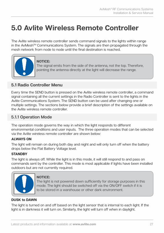
The Avlite wireless remote controller sends command signals to the lights within range in the AvMeshTM Communications System. The signals are then propagated through the mesh network from node to node until the final destination is reached.
Every time the SEND button is pressed on the Avlite wireless remote controller, a command signal containing all the current settings in the Radio Controller is sent to the lights in the Avlite Communications System. The SEND button can be used after changing one or multiple settings. The sections below provide a brief description of the settings available on the Avlite wireless remote controller.
The operation mode governs the way in which the light responds to different environmental conditions and user inputs. The three operation modes that can be selected via the Avlite wireless remote controller are shown below: ALWAYS ONThe light will remain on during both day and night and will only turn off when the battery drops below the Flat Battery Voltage level. STANDBYThe light is always off. While the light is in this mode, it will still respond to and pass on commands sent by the controller. This mode is most applicable if lights have been installed outdoors but are not currently required.
DUSK to DAWNThe light is turned on and off based on the light sensor that is internal to each light. If the light is in darkness it will turn on. Similarly, the light will turn off when in daylight.
5.0 Avlite Wireless Remote Controller
5.1 Radio Controller Menu
NOTICE:The signal emits from the side of the antenna, not the top. Therefore, pointing the antenna directly at the light will decrease the range.
5.1.1 Operation Mode
NOTICE:The light is not powered down sufficiently for storage purposes in this mode. The light should be switched off via the ON/OFF switch if it is to be stored in a warehouse or other dark environment.
28
The Avlite wireless remote controller provides users with the ability to illuminate remote runways in either the ‘Visible LEDs’ mode for normal runway operation or the ‘IR/NVG LEDs’ mode to support tactical operations.
Light groups are used to cluster lights in a particular area such as a taxiway so that they can be controlled independently from other light groups such as a runway or helipad. The Avlite Wireless Remote Controller offers 10 individual light groups (i.e. 0-9) as well as an option to select all groups at once.
The intensity of the LEDs in the lights can be set at either low, medium or high based on the users’ specifications (relative to 100% being specification level compliant).
The LED high intensity timeout feature allows the LEDs in the light to revert from high intensity to low intensity after a defined period of time (i.e. timeout duration). The three available timeout modes are described below:DisabledThe high intensity LED timeout is disabled. The LED intensity will be selected via the LED intensity menu.
5.1.4 Intensity
5.1.2 Advanced Op Mode
5.1.3 Light Group
NOTICE:The light group selected in the Avlite Wireless Remote Controller must be the same as the light group selected via the rotary switch in the light head in order for the light to respond to the controller.
NOTICE:• The LED Intensity is initially set ‘Low’ by default.• The ‘LED Intensity’ menu is not available for the STANDBY
operational mode.
5.1.5 Timeout Mode
NOTICE:This menu is not available if the STANDBY operational mode has been selected.

AvMesh® RF Communications SystemsInstallation & Service Manual
Latest products and information available at www.avlite.com 29
Enabled, STANDBYThe LED will turn OFF and enter the STANDBY operational mode after the set Timeout duration. Enabled, LOW The LED intensity will revert from the initial LED intensity to the LOW setting after the set Timeout duration.
The Timeout Duration is the period of time before the LED intensity reverts back to the LOW intensity state. This menu becomes available only when the Timeout Mode is enabled (i.e. the Timeout mode is set to Enabled LOW or Enabled STANDBY). The available timeout durations range from 1 minute to 60 minutes.
This feature is used to check the status of every light in the airfield. The command can be sent any time without affecting the current state of the light. The light will respond to the battery diagnostic in either a Yes/No flash response. For the ‘Yes’ response, the light will turn off for 1 second, turn on for 1 second and then turn off for 1 second. For the ‘No’ response, the light will turn off for 1 second, flash twice (i.e. the light will turn on for 0.3 seconds, turn off for 0.4 seconds then turn on again for 0.3 seconds) and then turn off for 1 second. • Battery (Flat) Yes: The Battery is below the flat threshold. No: The Battery is above the flat threshold.• Battery (Low) Yes: The Battery is below the low threshold but above the flat threshold. No: The Battery is above the low threshold but below the healthy threshold. • Battery (Healthy) Yes: The Battery is above the healthy threshold. No: The Battery is below the healthy threshold but above the low threshold.• Node (Reserve) Yes: The light is a reserve node in the reserve network. No: The light is not a reserve node.• Node (Primary) Yes: The light is a primary node in the primary network. No: The light is not a primary node. • External Power Yes: The light has an external power connection. No: The light does not have an external power connection.
5.1.6 Timeout Duration
5.1.7 Diagnostic

30
Changing the frequency channel and other features of the Avlite wireless remote controller can be accomplished by accessing the ‘Controller Setup Menu’. Press and hold the menu button on the Avlite wireless remote controller for 3 seconds to navigate to the ‘Controller Setup Menu’ and step through the menu options using the ‘Menu’ button. The following menu options are available: • Screen Backlight - A backlight percentage of 50% is used as the default setting but
can be changed to a value between 0-100%. • Connection Method - The 2 available connection methods are ‘Radio control’, which
is used for a standard wireless connection and ‘Direct connection’ which is used for programming the lights. See section 6.0 Direct Connection for more information. The connection method is set at ‘Radio Control’ as default.
• Flash Code Selection - The controller allows flash code selection as 3-digit numbers.• Advanced Operation - Select from either ‘Disable’ or ‘Enable’. The Advanced Operation
is set at ‘Enable’ as default. • Diagnostic - Select from either ‘Disable’ or ‘Enable’. The Diagnostic menu option is set
at ‘Enable’ as default. • Radio Information - Displays the unique ID code for the radio module. There are no
user adjustable settings for this menu option.• Radio Channel - Select from either ‘Encrypted’ or ‘Unencrypted’ then select a
hexadecimal number from 0x0c to 0x17. • Radio Encryption Key - The Avlite wireless remote radio controller has been
shipped preprogrammed with a default 128-bit encryption key. Although this does not need to be adjusted, the encryption key can be altered if required by the user via the arrow keys on the Avlite wireless remote controller. If the Avlite wireless remote controller becomes lost or broken, the encryption key can simply be entered into a new controller without the need to reprogram all the lights in the radio control system.
NOTICE:The radio encryption key for the lights must be the same as the key set in the Avlite wireless remote controller in order for the lights to respond to the controller. If the radio encryption key is changed from the default setting, it will be necessary to change the encryption key in ALL the lights in the system.
NOTICE:If the light is in STANDBY mode, it will respond to the diagnostic according to the above and then revert back to the STANDBY mode once the diagnostic has been completed.
5.2 Controller Menu (Advanced)

AvMesh® RF Communications SystemsInstallation & Service Manual
Latest products and information available at www.avlite.com 31
The Avlite wireless remote controller is able to program and communicate with individual lights in the system via physical connection. In the direct connection method, the Avlite wireless remote controller is connected to the light of interest via a programming cable. This allows the controller to send messages and commands to the individual light without the commands being sent to the other lights in the mesh network. It is possible to override the ‘natural’ network set-up procedure of the AvMeshTM Communications System and force a light to become a node (i.e. primary or reserve) via the direct connection method.
This procedure is applicable only for the AV-LA426.The process for forcing a light to be a primary node is below: 1. Turn the Avlite wireless remote controller on.2. After the initialization period, hold down the menu button for 3 seconds to enterthe
‘Controller Setup Menu’.3. Press the ‘Menu’ button twice to arrive at the ‘Connection Method’ menu option and
select ‘Direct Connection’ using the arrow keys.4. Press the ‘Send’ button and wait for the Avlite wireless remote controller to restart.5. Press the ‘Menu’ button until ‘AvMeshTM Node’ is displayed on the screen.6. Connect the Avlite wireless remote controller to the first light head.7. Select ‘Primary (Forced)’ using the arrow keys.8. Press ‘Send’ on the Avlite wireless remote controller. If successful, there should be a
tick next to the AvMeshTM Node title.9. Disconnect the Avlite wireless remote controller from the light and connect it to the
next light. 10. Repeat steps 8 and 9. This process can be used to force a reserve node by selecting ‘Reserve (Forced)’ in step 7.
6.0 Direct Connection
6.1 To Force A Primary Node via Direct Connection

32
The light group and node assignment of a particular light in the system can be set via rotary switches ‘A’ and ‘B’ located on the bottom of the circuit board in the light head. The switches are usually set to ‘0’ in the factory. Rotary switch B sets the node type. If the switch is set to ‘A’, the particular node will be assigned to the primary network and hence, it will be a primary node. If the switch is set to ‘B’, the particular node will be assigned to the reserve network and will be a reserve node. Rotary switch A sets the light group of the light. There are 10 available light groups (i.e. 0-9) as well as a setting to select all light groups at once.
1. Turn the Light off.2. Remove the bung underneath the circuit board in the light head. Set rotary switch A to
‘0’ and set rotary switch B to ‘A’. 3. Refit the bung.4. Turn the light on. This process can be used to force a reserve node by setting rotary switch B to ‘B’.
Since the light fixtures (i.e. AV-70 and AV-426) are designed to be installed close to the ground, there is a high possibility that the first Fresnel zone will not be cleared because it will be impinged by the surface of the Earth and obstruct the signal propagation between the lights. It is therefore important to raise the heights of the lights as high as possible (while still conforming to the required regulations) so that the antennas are higher and more likely to clear the first Fresnel zone (or a minimum of 60% of the first Fresnel zone). It is also important to consider other obstacles that may impact the propagation of the RF signal such as long grass, gables, dips and crests. Furthermore, it is also important to keep the height of vegetation around the lights as low as possible so that RF propagation is not obstructed. The Avlite wireless remote controller should also be raised as high as possible to clear the first Fresnel zone and maintain signal strength between the controller and the lights within range. The use of the control tower or other raised primary control location is therefore essential for this purpose.
8.0 Maintenance/Housekeeping of the AvMeshTM Communications System
7.1 To Force A Primary Node via Rotary Switches
7.0 Rotary Switches

AvMesh® RF Communications SystemsInstallation & Service Manual
Latest products and information available at www.avlite.com 33
The AvMeshTM Communications System has been designed to be a resilient network that requires minimal maintenance and offers years of trouble-free service. However, in the occurrence of any faults or issues (the cause of which could be a number of factors) a series of flowcharts have been provided to guide you through a structured approach to identify and solve the problem as a preliminary step to contacting the Avlite technical services team.
9.0 Troubleshooting
9.1 Identifying the Problem Airfield not functioning as expected
Start
Is the whole airfield non-functional?
Consult the ‘Whole airfield non-functional’ flowchart
YES
Is a single fixture unresponsive?
Consult the ‘Single fixture non-functional’ flowchart
YES
NOConsult the ‘Multiple
fixtures non-functional’ flowchart
NO
End End
End
Start
Is the whole airfield non-functional?
Consult the ‘Whole airfield non-functional’ flowchart
YES
Is a single fixture unresponsive?
Consult the ‘Single fixture non-functional’ flowchart
YES
NOConsult the ‘Multiple
fixtures non-functional’ flowchart
NO
End End
End

34
Single fixture unresponsiveStart
Check Battery Voltage
Is Battery voltage above flat battery threshold? (Refer to
the appropriate product user manual).
Charge Battery
NO
End
Attempt to control fixture from close
proximity with handheld controller
Does light respond?
End
Verify that RF parameters (i.e. channel, light group and encryption) on RF
controller and light fixture match
NO
YES
Do RF parameters
match?
Contact Avlite technical services
Change RF parameters on light fixture or RF
controller
Attempt to control fixture from close
proximity with handheld controller
Does light respond?
Contact Avlite technical services
End
YES
YES
NO
YES
NO
Start
Check Battery Voltage
Is Battery voltage above flat battery threshold? (Refer to
the appropriate product user manual).
Charge Battery
NO
End
Attempt to control fixture from close
proximity with handheld controller
Does light respond?
End
Verify that RF parameters (i.e. channel, light group and encryption) on RF
controller and light fixture match
NO
YES
Do RF parameters
match?
Contact Avlite technical services
Change RF parameters on light fixture or RF
controller
Attempt to control fixture from close
proximity with handheld controller
Does light respond?
Contact Avlite technical services
End
YES
YES
NO
YES
NO
9.2 Single Fixture Non-functional

AvMesh® RF Communications SystemsInstallation & Service Manual
Latest products and information available at www.avlite.com 35
Whole runway unresponsiveStart
Check Controller
Battery
Is Controller Battery in spec?
Charge Battery
EndNO
Take a sample of fixtures and check all batteries are in
spec.
YES
Are all batteries in
spec?
Check batteries of all fixtures on
runway
Are all batteries in
spec?
Charge batteries
EndNO
YES
Check if whole runway becomes responsive
when in close proximity to a fixture
YES
NO
Is whole runway responsive?
Verify that RF parameters (i.e. channel, light group and encryption) on RF
controller and light fixture match
NO
YES
Attempt to activate and deactivate lights while making
way back to control tower. Take note of the distance at
which the lights become unreponsive.
Do RF parameters
match?
Change RF parameters on light
fixture or RF controller
NO
Contact Avlite technical services
YES
1. Use repeaters to bridge distance from control tower to point at which lights become
unresponsive.2. Install a high gain antenna.
Check if whole runway becomes responsive.
Is whole runway responsive?
Contact Avlite technical services
End
NO
YES
Start
Check Controller
Battery
Is Controller Battery in spec?
Charge Battery
EndNO
Take a sample of fixtures and check all batteries are in
spec.
YES
Are all batteries in
spec?
Check batteries of all fixtures on
runway
Are all batteries in
spec?
Charge batteries
EndNO
YES
Check if whole runway becomes responsive
when in close proximity to a fixture
YES
NO
Is whole runway responsive?
Verify that RF parameters (i.e. channel, light group and encryption) on RF
controller and light fixture match
NO
YES
Attempt to activate and deactivate lights while making
way back to control tower. Take note of the distance at
which the lights become unreponsive.
Do RF parameters
match?
Change RF parameters on light
fixture or RF controller
NO
Contact Avlite technical services
YES
1. Use repeaters to bridge distance from control tower to point at which lights become
unresponsive.2. Install a high gain antenna.
Check if whole runway becomes responsive.
Is whole runway responsive?
Contact Avlite technical services
End
NO
YES
9.3 Whole Runway Non-functional

36
9.4 Multiple Fixtures Non-functional
Gaps in runway
Is whole runway responsive?
End
YES
Test system at long range
Verify radio interference at failure areas using spectrum
analyzer with directional antenna, pointing to potential
sources of interference
Clear indication of interference?
Send information to
Avlite
YES
NO
Increase frequency span and check for
operating traffic outside the 2.4GHz
region
Clear indication of interference?
Send information to
Avlite
YES
NO
NO
Verify radio interference using spectrum analyzer with directional antenna,
pointing to potential sources of interference
Clear indication of interference?
Send information to
Avlite
YES
Contact Avlite technical services
NO
Start
Check housekeeping:-Grass is mowed around
runway-Line of sight is attainable
-Lights are on-Maximum distance
between lights
Test system using radio controller at
primary control location (i.e. long range)
Is whole runway responsive?
Perform tests at short range and modify each lantern from STANDBY
to ALWAYS ON
Is whole runway responsive at short range?
Verify that RF parameters (i.e. channel, light group and encryption) on RF
controller matches with the light fixtures
End
Do RF parameters
match?
Contact Avlite technical services
NO
YES
NO
Force primary node on closest functional
nodes adjacent to dead spot.
YES
Change RF parameters on
light fixture or RF controller
YES
Is whole runway responsive?
Test system from long range
End
NO Install repeaters in areas adjacent to and around dead spots as recommended by
Avlite technical services
Test system at long range
See next page...
NO
YES

AvMesh® RF Communications SystemsInstallation & Service Manual
Latest products and information available at www.avlite.com 37
Gaps in runway
Is whole runway responsive?
End
YES
Test system at long range
Verify radio interference at failure areas using spectrum
analyzer with directional antenna, pointing to potential
sources of interference
Clear indication of interference?
Send information to
Avlite
YES
NO
Increase frequency span and check for
operating traffic outside the 2.4GHz
region
Clear indication of interference?
Send information to
Avlite
YES
NO
NO
Verify radio interference using spectrum analyzer with directional antenna,
pointing to potential sources of interference
Clear indication of interference?
Send information to
Avlite
YES
Contact Avlite technical services
NO
Is whole runway responsive?
End
YES
Test system at long range
Verify radio interference at failure areas using spectrum
analyzer with directional antenna, pointing to potential
sources of interference
Clear indication of interference?
Send information to
Avlite
YES
NO
Increase frequency span and check for
operating traffic outside the 2.4GHz
region
Clear indication of interference?
Send information to
Avlite
YES
NO
NO
Verify radio interference using spectrum analyzer with directional antenna,
pointing to potential sources of interference
Clear indication of interference?
Send information to
Avlite
YES
Contact Avlite technical services
NO
Start
Check housekeeping:-Grass is mowed around
runway-Line of sight is attainable
-Lights are on-Maximum distance
between lights
Test system using radio controller at
primary control location (i.e. long range)
Is whole runway responsive?
Perform tests at short range and modify each lantern from STANDBY
to ALWAYS ON
Is whole runway responsive at short range?
Verify that RF parameters (i.e. channel, light group and encryption) on RF
controller matches with the light fixtures
End
Do RF parameters
match?
Contact Avlite technical services
NO
YES
NO
Force primary node on closest functional
nodes adjacent to dead spot.
YES
Change RF parameters on
light fixture or RF controller
YES
Is whole runway responsive?
Test system from long range
End
NO Install repeaters in areas adjacent to and around dead spots as recommended by
Avlite technical services
Test system at long range
See next page...
NO
YES
Start
Check housekeeping:-Grass is mowed around
runway-Line of sight is attainable
-Lights are on-Maximum distance
between lights
Test system using radio controller at
primary control location (i.e. long range)
Is whole runway responsive?
Perform tests at short range and modify each lantern from STANDBY
to ALWAYS ON
Is whole runway responsive at short range?
Verify that RF parameters (i.e. channel, light group and encryption) on RF
controller matches with the light fixtures
End
Do RF parameters
match?
Contact Avlite technical services
NO
YES
NO
Force primary node on closest functional
nodes adjacent to dead spot.
YES
Change RF parameters on
light fixture or RF controller
YES
Is whole runway responsive?
Test system from long range
End
NO Install repeaters in areas adjacent to and around dead spots as recommended by
Avlite technical services
Test system at long range
See next page...
NO
YES

38
Notes

AvMesh® RF Communications SystemsInstallation & Service Manual
Latest products and information available at www.avlite.com 39

Avlite Solution Verticals available
Avlite SystemsAustralia+61 (0)3 5977 6128
Avlite Asia Pte LtdSingapore+65 6908 2917
Avlite USA LLCUSA+1 (603) 737 1311
We believe technology improves navigationTM
avlite.com [email protected]
Airfield
Heliport
Obstruction