Embed Size (px)
Citation preview
1Copyright 2006 Fulllinks Co., Ltd. All rights reserved.
2008. 01
AVL (Automatic Vehicle Location) System
Product : AVL-2000G (GSM/GPRS)
2Copyright 2006 Fulllinks Co., Ltd. All rights reserved.
1. Overview
2. Product Introduction
3. Product Function
4. Product Composition
Contests
3Copyright 2006 Fulllinks Co., Ltd. All rights reserved.
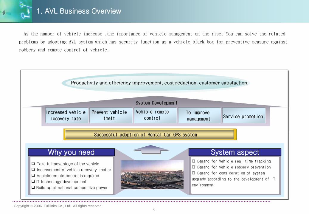
Why you need
Take full advantage of the vehicle
Incensement of vehicle recovery matter
Vehicle remote control is required
IT technology development
Build up of national competitive power
Demand for Vehicle real time tracking
Demand for vehicle robbery prevention
Demand for consideration of system
upgrade according to the development of IT
environment
System aspect
Productivity and efficiency improvement, cost reduction, customer satisfaction
System Development
Successful adoption of Rental Car GPS system
1. AVL Business Overview
As the number of vehicle increase ,the importance of vehicle management on the rise. You can solve the related
problems by adopting AVL system which has security function as a vehicle black box for preventive measure against
robbery and remote control of vehicle.
Increased vehicle
recovery rate
Prevent vehicle
theft
Vehicle remote
controlTo improve
management Service promotion
4Copyright 2006 Fulllinks Co., Ltd. All rights reserved.
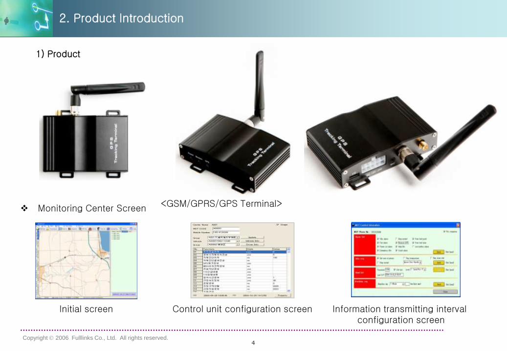
Initial screen Control unit configuration screen Information transmitting intervalconfiguration screen
2. Product Introduction
Monitoring Center Screen
1) Product
<GSM/GPRS/GPS Terminal>
5Copyright 2006 Fulllinks Co., Ltd. All rights reserved.
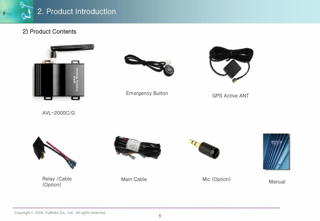
2) Product Contents
Manual
2. Product Introduction
AVL-2000C/G
Main Cable
GPS Active ANTEmergency Button
Relay /Cable (Option)
Mic (Option)
6Copyright 2006 Fulllinks Co., Ltd. All rights reserved.
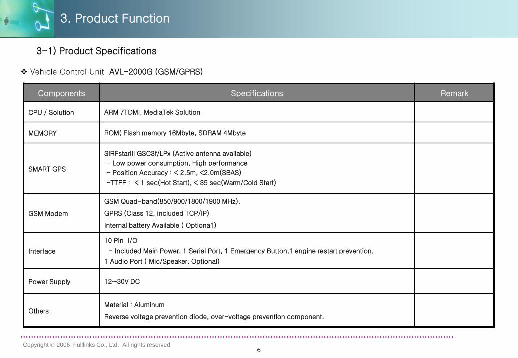
Components Specifications Remark
CPU / Solution ARM 7TDMI, MediaTek Solution
MEMORY ROM( Flash memory 16Mbyte, SDRAM 4Mbyte
SMART GPS
SiRFstarIII GSC3f/LPx (Active antenna available)
- Low power consumption, High performance
- Position Accuracy : < 2.5m, <2.0m(SBAS)
-TTFF : < 1 sec(Hot Start), < 35 sec(Warm/Cold Start)
GSM Modem
GSM Quad-band(850/900/1800/1900 MHz),
GPRS (Class 12, included TCP/IP)
Internal battery Available ( Optiona1)
Interface
10 Pin I/O
- Included Main Power, 1 Serial Port, 1 Emergency Button,1 engine restart prevention.
1 Audio Port ( Mic/Speaker, Optional)
Power Supply 12~30V DC
OthersMaterial : Aluminum
Reverse voltage prevention diode, over-voltage prevention component.
Vehicle Control Unit AVL-2000G (GSM/GPRS)
3-1) Product Specifications
3. Product Function
7Copyright 2006 Fulllinks Co., Ltd. All rights reserved.
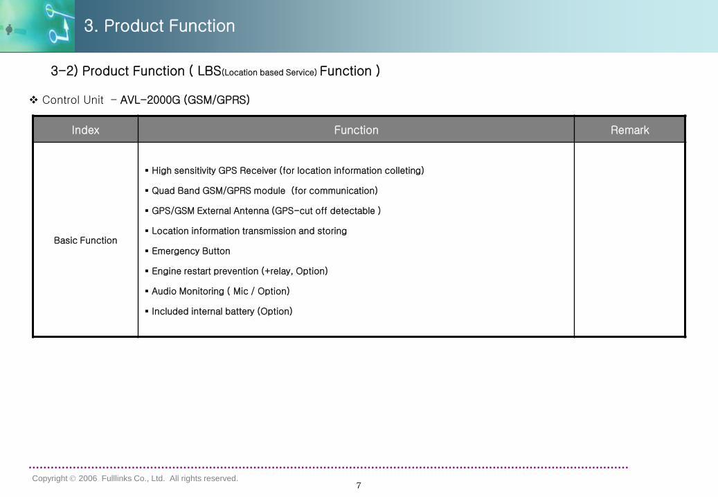
3-2) Product Function ( LBS(Location based Service) Function )
Index Function Remark
Basic Function
High sensitivity GPS Receiver (for location information colleting)
Quad Band GSM/GPRS module (for communication)
GPS/GSM External Antenna (GPS-cut off detectable )
Location information transmission and storing
Emergency Button
Engine restart prevention (+relay, Option)
Audio Monitoring ( Mic / Option)
Included internal battery (Option)
Control Unit – AVL-2000G (GSM/GPRS)
3. Product Function
8Copyright 2006 Fulllinks Co., Ltd. All rights reserved.
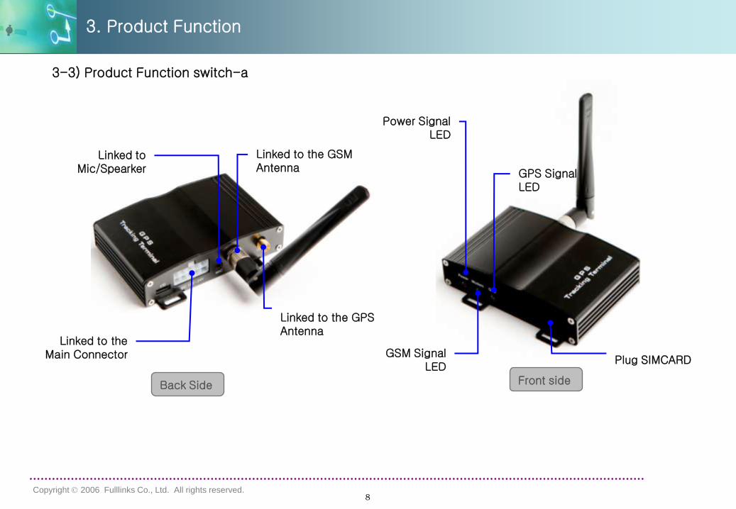
Linked to the GPS Antenna
Linked to the GSM Antenna
Linked to theMain Connector
GPS Signal LED
GSM Signal LED
Power Signal LED
Plug SIMCARD
Front side Back Side
3-3) Product Function switch-a
Linked to Mic/Spearker
3. Product Function
9Copyright 2006 Fulllinks Co., Ltd. All rights reserved.
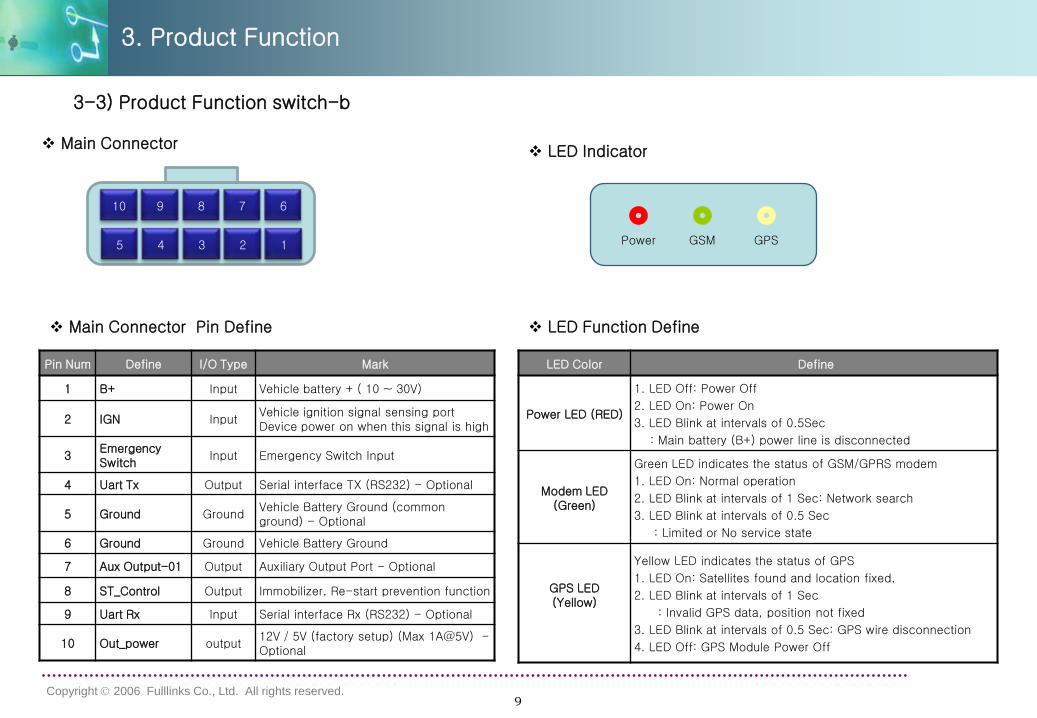
Pin Num Define I/O Type Mark
1 B+ Input Vehicle battery + ( 10 ~ 30V)
2 IGN InputVehicle ignition signal sensing port Device power on when this signal is high
3Emergency Switch
Input Emergency Switch Input
4 Uart Tx Output Serial interface TX (RS232) - Optional
5 Ground GroundVehicle Battery Ground (common ground) - Optional
6 Ground Ground Vehicle Battery Ground
7 Aux Output-01 Output Auxiliary Output Port - Optional
8 ST_Control Output Immobilizer, Re-start prevention function
9 Uart Rx Input Serial interface Rx (RS232) - Optional
10 Out_power output12V / 5V (factory setup) (Max 1A@5V) -Optional
5 4 3 2 1
10 9 8 7 6
Main Connector Pin Define
3-3) Product Function switch-b
LED Color Define
Power LED (RED)
1. LED Off: Power Off
2. LED On: Power On
3. LED Blink at intervals of 0.5Sec
: Main battery (B+) power line is disconnected
Modem LED (Green)
Green LED indicates the status of GSM/GPRS modem
1. LED On: Normal operation
2. LED Blink at intervals of 1 Sec: Network search
3. LED Blink at intervals of 0.5 Sec
: Limited or No service state
GPS LED (Yellow)
Yellow LED indicates the status of GPS
1. LED On: Satellites found and location fixed,
2. LED Blink at intervals of 1 Sec
: Invalid GPS data, position not fixed
3. LED Blink at intervals of 0.5 Sec: GPS wire disconnection
4. LED Off: GPS Module Power Off
LED Function Define
Power GSM GPS
LED Indicator Main Connector
3. Product Function
10Copyright 2006 Fulllinks Co., Ltd. All rights reserved.
5 4 3 2 1
10
9 8 7 6
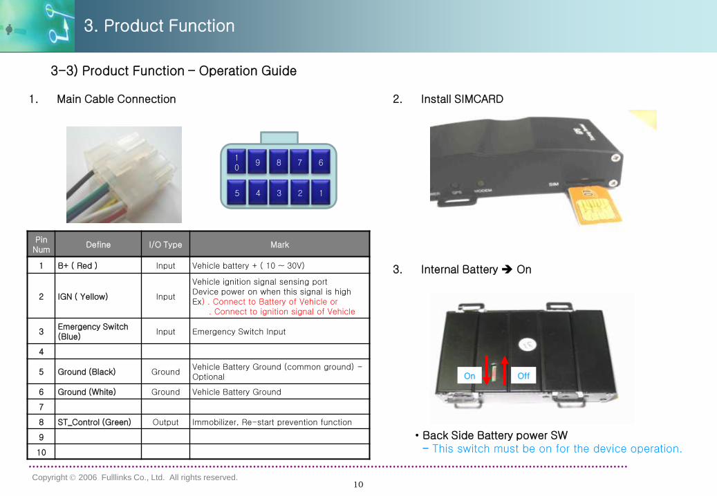
3-3) Product Function – Operation Guide
1. Main Cable Connection
3. Product Function
Pin Num
Define I/O Type Mark
1 B+ ( Red ) Input Vehicle battery + ( 10 ~ 30V)
2 IGN ( Yellow) Input
Vehicle ignition signal sensing port Device power on when this signal is highEx) . Connect to Battery of Vehicle or
. Connect to ignition signal of Vehicle
3Emergency Switch (Blue)
Input Emergency Switch Input
4
5 Ground (Black) GroundVehicle Battery Ground (common ground) -Optional
6 Ground (White) Ground Vehicle Battery Ground
7
8 ST_Control (Green) Output Immobilizer, Re-start prevention function
9
10
3. Internal Battery On
On Off
• Back Side Battery power SW- This switch must be on for the device operation.
2. Install SIMCARD
11Copyright 2006 Fulllinks Co., Ltd. All rights reserved.
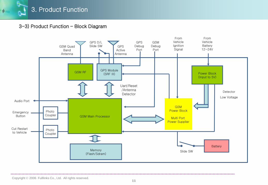
3-3) Product Function – Block Diagram
3. Product Function
GSM RFGPS Module
(SRF III)
GSM Main Processor
Memory(Flash/Sdram)
GSM Quad Band
Antenna
GPS Active
Antenna
Uart/Reset /Antenna Detector
Power Block(Input to 5V)
From Vehicle Battery 12~24V
GSMPower Block
Multi Port Power Supplier
From Vehicle Ignition Signal
Battery
Slide SW
GPS Debug Port
GSM Debug Port
GPS D/L Slide SW
Emergency Button
Photo Coupler
Photo Coupler
Cut Restart to Vehicle
Detector
Low VoltageAudio Port
12Copyright 2006 Fulllinks Co., Ltd. All rights reserved.
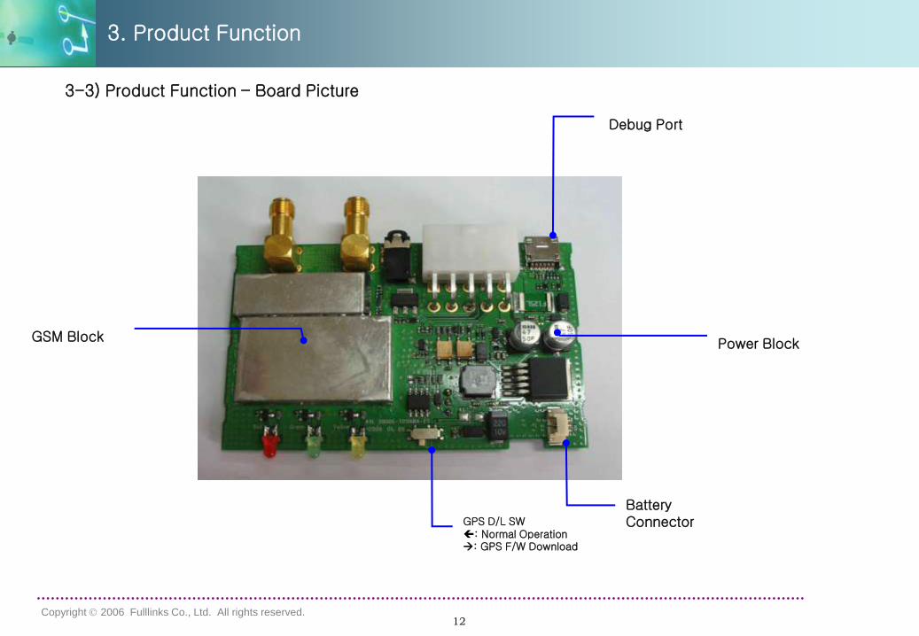
3-3) Product Function – Board Picture
3. Product Function
Debug Port
Battery ConnectorGPS D/L SW
: Normal Operation: GPS F/W Download
Power BlockGSM Block
13Copyright 2006 Fulllinks Co., Ltd. All rights reserved.
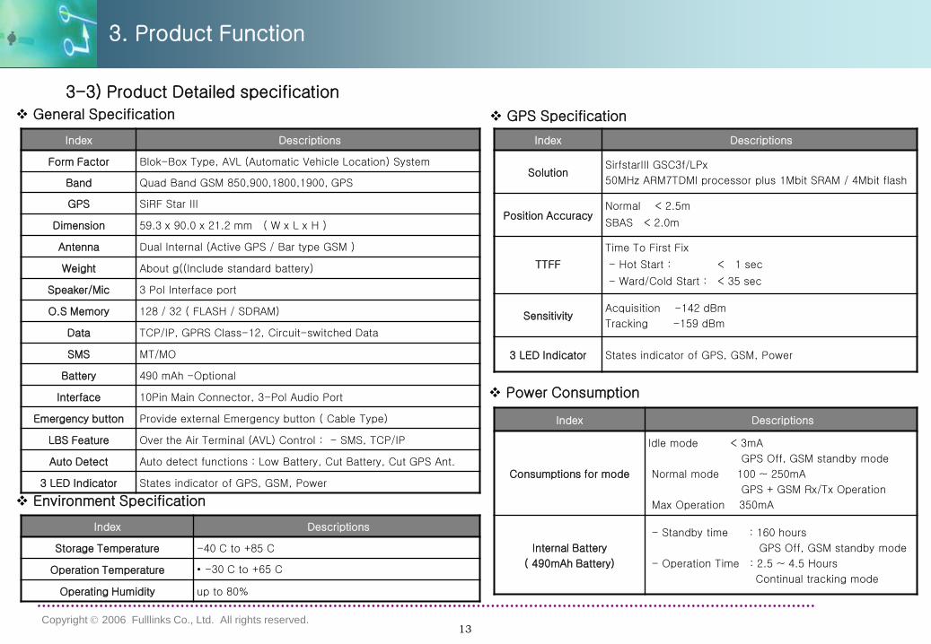
3-3) Product Detailed specification
Index Descriptions
Form Factor Blok-Box Type, AVL (Automatic Vehicle Location) System
Band Quad Band GSM 850,900,1800,1900, GPS
GPS SiRF Star III
Dimension 59.3 x 90.0 x 21.2 mm ( W x L x H )
Antenna Dual Internal (Active GPS / Bar type GSM )
Weight About g((Include standard battery)
Speaker/Mic 3 Pol Interface port
O.S Memory 128 / 32 ( FLASH / SDRAM)
Data TCP/IP, GPRS Class-12, Circuit-switched Data
SMS MT/MO
Battery 490 mAh -Optional
Interface 10Pin Main Connector, 3-Pol Audio Port
Emergency button Provide external Emergency button ( Cable Type)
LBS Feature Over the Air Terminal (AVL) Control : - SMS, TCP/IP
Auto Detect Auto detect functions : Low Battery, Cut Battery, Cut GPS Ant.
3 LED Indicator States indicator of GPS, GSM, Power
General Specification
Index Descriptions
Storage Temperature -40 C to +85 C
Operation Temperature • -30 C to +65 C
Operating Humidity up to 80%
Environment Specification
GPS Specification
Index Descriptions
SolutionSirfstarIII GSC3f/LPx
50MHz ARM7TDMI processor plus 1Mbit SRAM / 4Mbit flash
Position AccuracyNormal < 2.5m
SBAS < 2.0m
TTFF
Time To First Fix
- Hot Start : < 1 sec
- Ward/Cold Start : < 35 sec
SensitivityAcquisition -142 dBm
Tracking -159 dBm
3 LED Indicator States indicator of GPS, GSM, Power
Power Consumption
Index Descriptions
Consumptions for mode
Idle mode < 3mA
GPS Off, GSM standby mode
Normal mode 100 ~ 250mA
GPS + GSM Rx/Tx Operation
Max Operation 350mA
Internal Battery
( 490mAh Battery)
- Standby time : 160 hours
GPS Off, GSM standby mode
- Operation Time : 2.5 ~ 4.5 Hours
Continual tracking mode
3. Product Function
14Copyright 2006 Fulllinks Co., Ltd. All rights reserved.
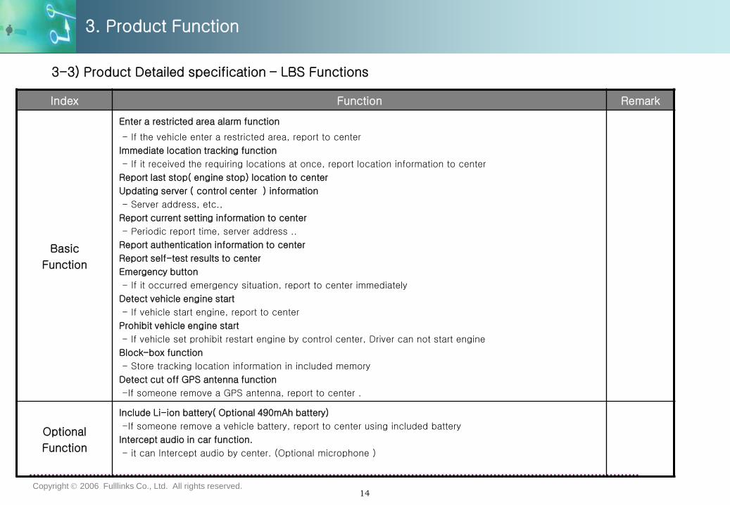
Index Function Remark
Basic
Function
Enter a restricted area alarm function
- If the vehicle enter a restricted area, report to center
Immediate location tracking function
- If it received the requiring locations at once, report location information to center
Report last stop( engine stop) location to center
Updating server ( control center ) information
- Server address, etc.,
Report current setting information to center
- Periodic report time, server address ..
Report authentication information to center
Report self-test results to center
Emergency button
- If it occurred emergency situation, report to center immediately
Detect vehicle engine start
- If vehicle start engine, report to center
Prohibit vehicle engine start
- If vehicle set prohibit restart engine by control center, Driver can not start engine
Block-box function
- Store tracking location information in included memory
Detect cut off GPS antenna function
-If someone remove a GPS antenna, report to center .
Optional
Function
Include Li-ion battery( Optional 490mAh battery)
-If someone remove a vehicle battery, report to center using included battery
Intercept audio in car function.
- it can Intercept audio by center. (Optional microphone )
3-3) Product Detailed specification – LBS Functions
3. Product Function
15Copyright 2006 Fulllinks Co., Ltd. All rights reserved.
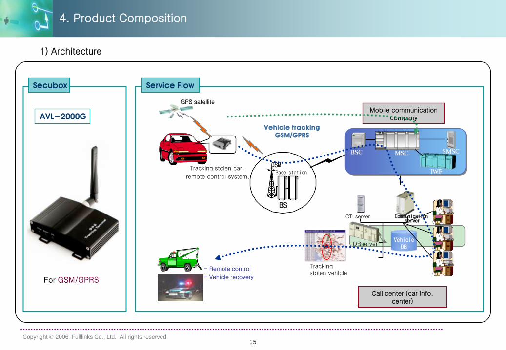
4. Product Composition
Secubox Service Flow
Tracking stolen car,
remote control system,
GPS satellite
Base station
GSM
BS
Call center (car info. center)
Vehicle trackingGSM/GPRS
MSCBSC SMSC
IWF
Mobile communication company
Vehicle DB
Communication server
CTI server
DBserver
- Remote control
- Vehicle recovery
Tracking stolen vehicle
차량도난
AVL-2000G
1) Architecture
16Copyright 2006 Fulllinks Co., Ltd. All rights reserved.
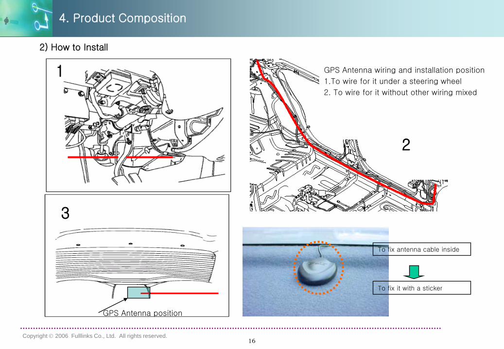
1
2
3
GPS Antenna wiring and installation position
1.To wire for it under a steering wheel
2. To wire for it without other wiring mixed
To fix antenna cable inside
To fix it with a sticker
GPS Antenna position
2) How to Install
GPS Antenna wiring and installation position
1.To wire for it under a steering wheel
2. To wire for it without other wiring mixed
4. Product Composition
17Copyright 2006 Fulllinks Co., Ltd. All rights reserved.
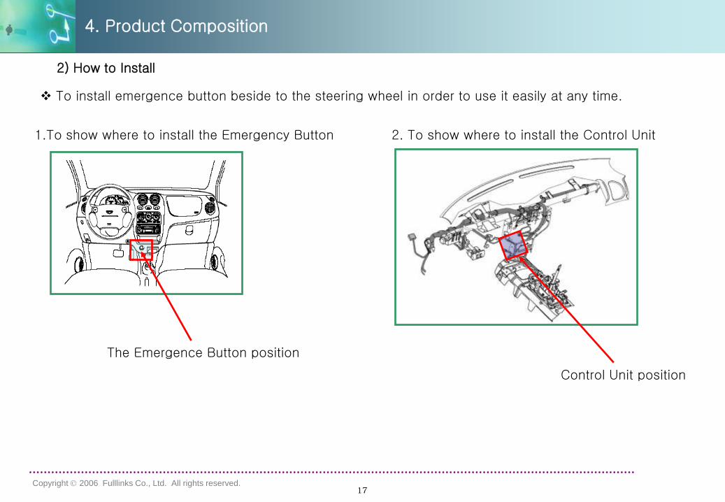
To install emergence button beside to the steering wheel in order to use it easily at any time.
1.To show where to install the Emergency Button 2. To show where to install the Control Unit
Control Unit position
The Emergence Button position
4. Product Composition
2) How to Install