Embed Size (px)
Citation preview

Aviation Safety Support Services for the Bureau of Safety and Environmental Enforcement
Task C.4.5: Study on Effects of Combustible Gas on Helicopter Operations
August 31, 2015

Aviation Safety Support Services for BSEE
Task C.4.5: Study on Effects of Combustible Gas on
Helicopter Operations
2 of 105
Table of Contents
Abbreviations and Acronyms .................................................................................... 4
Introduction....................................................................................................... 6 1. Other Mishaps Consistent With APG Ingestion .............................................................7 1.1
Analysis ...........................................................................................................12 2. Subtask C.4.5.1 – review and assess helideck construction standards .........................12 2.1
Subtask C.4.5.2 (a) – conduct technical analysis ..........................................................32 2.2
Subtask C.4.5.2 (b) – identify and list each helicopter (make, model, and engine) 2.3
used on OCS facilities under BSEE jurisdiction. ..........................................................34
Subtask C.4.5.2 (c) – (1) determine the vapor density for each flammable gas 2.4
(lighter or heavier than air) to determine how the placement of vents would
affect helicopter operations; and (2) determine the flammability limits for each
flammable gas to determine the effect on helicopter operations...................................35 Subtask C.4.5.2 (d) – (1) determine the concentration parameters for each 2.5
flammable gas to determine the effect on helicopter operations...................................38
Subtask C.4.5.2 (d) – (2) specifically identify if each helicopter engine 2.6
manufacturer has a known percentage of methane (or other combustible gas) to
volume that is hazardous to engine operations. ............................................................39 Subtask C.4.5.2 (e) – evaluate the effect of the ingestion of each combustible gas 2.7
on each helicopter (make, model, and engine), at anticipated concentration
levels. ............................................................................................................................41
Subtask C.4.5.3 – monitoring and warning systems .....................................................59 2.8
Recommendations ...........................................................................................63 3. Subtask C.4.5.1 – review and assess helideck construction standards .........................63 3.1
Subtask C.4.5.2 (a) – identify and list each regulation that addresses venting and 3.2
flaring of methane on OCS facilities under BSEE jurisdiction, highlighting any
regulation that favors one method over the other..........................................................63 Subtask C.4.5.2 (d) – (1) determine the concentration parameters for each 3.3
flammable gas to determine the effect on helicopter operations; and (2)
specifically identify if each helicopter engine manufacturer has a known
percentage of methane (or other combustible gas) to volume that is hazardous to
engine operations. .........................................................................................................63 Subtask C.4.5.2 (e) – evaluate the effect of the ingestion of each combustible gas 3.4
on each helicopter (make, model, and engine), at anticipated concentration
levels. ............................................................................................................................64
Subtask C.4.5.3 (a) – monitoring technologies .............................................................65 3.5
Subtask C.4.5.3 (b) – mitigation strategies ...................................................................66 3.6
References .......................................................................................................67 4.
Appendix A-NTSB CEN11LA252 ..................................................................73 5.
Aviation Safety Support Services for BSEE
Task C.4.5: Study on Effects of Combustible Gas on
Helicopter Operations
3 of 105
Appendix B-NTSB CEN13FA491 ..................................................................79 6.
Appendix C-NTSB Safety Recommendations A-14-67-through 71 .............88 7.
Appendix D-Representative OCS Platforms ................................................102 8.
Appendix E – Helicopters Operating on the OCS .......................................104 9.
Appendix F-Preliminary Engineering Analysis Report-(attached as 10.
separate document) .......................................................................................105
Table of Figures
Figure 1: Helideck Orientation Based on Wind Direction/Exhaust Discharges ............................16
Figure 2: CFD Model, Isothermic Dispersion 1 ............................................................................28 Figure 3: CFD Model, Isothermic Dispersion 2 ............................................................................29
Figure 4: Platform Wind Distribution with Least Favorable Conditions ......................................30 Figure 5: CFD Gas Dispersion Model Example 1 .........................................................................30 Figure 6: CFD Gas Dispersion Model Example 2 .........................................................................31
Figure 7: CFD Gas Dispersion Model Example 3 .........................................................................31 Figure 8: APG Dethanization Process ...........................................................................................36
Figure 9: Off-Gas Incinerator Process (Flare) ...............................................................................36 Figure 10: Airflow Schematic for Allison 250-C20J .....................................................................42 Figure 11: Gas Turbine Engine Brayton Cycle..............................................................................44
Figure 12: Example of Gas Turbine Engine Compressor Map......................................................45
Figure 13: Hydromechanical Fuel Control System for Rolls-Royce Allison 250 Turboshaft
Engine .........................................................................................................................48 Figure 14: Normal and Category B Takeoff and Emergency Flight Paths ....................................51
Figure 15: Category A Takeoff and Emergency Flight Paths........................................................52 Figure 16: Conventional Approach and Landing Flight Path ........................................................53 Figure 17: APG Ingestion Event Tree ...........................................................................................55
Figure 18: No Approaches or Departures Wind Zone Depiction ..................................................66
Table of Tables
Table 1: Approximate APG Composition and Physical Properties ...............................................37
Aviation Safety Support Services for BSEE
Task C.4.5: Study on Effects of Combustible Gas on
Helicopter Operations
4 of 105
Abbreviations and Acronyms
APG – Associated petroleum gases (methane, ethane, propane, and butane).
API – American Petroleum Institute
ANAC - National Civil Aviation Agency (of Brazil)
BACT - Best Available Control Technology
BSEE - Bureau of Safety and Environmental Enforcement
CAA – UK Civil Aviation Authority
CASA - Civil Aviation Safety Authority (of Australia)
CFD – Computational Fluid Dynamics
CONUS – Continental United States
EASA - European Aviation Safety Agency
EPA – Environmental Protection Agency
EEZ - Exclusive Economic Zone
FAA – Federal Aviation Administration
FADEC - Full Authority Digital Engine Control
FATO - Final Approach and Takeoff Area
FPSO - Floating Production and Storage Offloading equipment
HAI - Helicopter Association International
HMS - Helicopter Monitoring System
HSAC – Helicopter Safety Advisory Conference
ICAO - International Civil Aviation Organization
IFR - Instrument Flight Rules

Aviation Safety Support Services for BSEE
Task C.4.5: Study on Effects of Combustible Gas on
Helicopter Operations
5 of 105
INAC - Instituto Nacional de Aviação Civil (of Angola)
ISO - International Standards Organization
IUPAC - International Union for Pure and Applied Chemistry
Jet A – aviation turbine fuel specification for Jet A and Jet A-1 in accordance with ASTM
D1655.
LFL - Lower Flammable Limit
MGTOW - Maximum Gross Takeoff Weight
MIE - Minimum Ignition Energy
MODU – Mobile Offshore Drilling Unit
NAAQS - National Ambient Air Quality Standards
NIST - National Institute for Standards and Technology
NORSOK – (Norsk Sokkels Konkuranseposisjon) standards developed by the Norwegian
Technology Centre
NTSB - National Transportation Safety Board
OCS – Outer Continental Shelf
OSHA - Occupational Safety and Health Administration
PMx - Particulate Matter
PORV - Pressure Operated Relieve Valves
PSD - Prevention of Significant Deterioration
USCG - United States Coast Guard
VCE - Vapor Cloud Explosion
VFR - Visual Flight Rules
VOC - Volatile Organic Compounds

Aviation Safety Support Services for BSEE
Task C.4.5: Study on Effects of Combustible Gas on
Helicopter Operations
6 of 105
Introduction 1.
As a result of two offshore helicopter mishaps involving support of the Outer Continental Shelf
(OCS) oil & gas industry (and possibly others), the National Transportation Safety Board
(NTSB) issued five safety recommendations to the U.S. Department of the Interior, the United
States Coast Guard, and the American Petroleum Institute, to address occurrences of total or
partial loss of engine power on turbine-powered helicopters due to inadvertent ingestion of
methane gas1
As a result of the NTSB safety recommendations, the Bureau of Safety and Environmental
Enforcement (BSEE) issued Solicitation, Contract and Award No. E14PS00012, Aviation Safety
Support for the Bureau of Safety and Environmental Enforcement. C.4.5 Task 5 of this contract
requires the assessment of potential effects to helicopter operations of methane and other
combustible gasses on or near OCS helidecks to identify and mitigate or eliminate risks.
In 2011, Baker, Shanahan, and Haaland, et al, researched helicopter crashes related to offshore
oil and gas operations in the Gulf of Mexico (GOM). The authors found that during the 26 year
period from 1983 to 2009, 178 helicopters crashed in the GOM, nearly seven per year. 54
crashes (30%) involved 139 fatal injuries. The predominant failure in the mishaps was partial or
total loss of engine power which occurred in 31% of fatal crashes and 71% of nonfatal crashes.
The causes of the engine failures were varied, including engine component failures, foreign
object debris ingestion, fuel contamination, and fuel starvation.
Bell 206L-3, N32041 at Main Pass 61A, March 24, 2011 (NTSB CEN11LA252)2
On 24 March 2011, about 1655 central daylight time, a Bell 206‐L3 helicopter experienced a
partial loss of power to its Allison 250‐C30 turboshaft engine shortly after takeoff from an
offshore oil production platform in the Gulf of Mexico. The commercial pilot initiated an
autorotation and activated the helicopter’s float system; the helicopter impacted the water and
rolled inverted. The pilot and two passengers received minor injuries, and the helicopter was
substantially damaged. The pilot and passengers reported hearing a loud bang just after the
helicopter departed the platform, toward the northwest, into the wind. After hearing the bang, the
pilot observed a high indication on the torque gauge and initiated an autorotation, stating that the
aircraft was above and just beyond an “exhaust pipe” on the platform but that he did not know
what it vented or whether it was venting when the takeoff was initiated.
The platform operator reported that the flare boom was venting methane throughout the day,
including the time of the helicopter’s departure. The offshore facility was not equipped to
provide any visual indication when hydrocarbon gases were venting. Review of the data from the
helicopter’s full authority digital engine control (FADEC) system revealed a slight increase in
engine torque and turbine outlet temperature. The National Transportation Safety Board (NTSB)
determined the probable cause of this mishap as “the loss of engine power due to an engine
1 Appendix C-NTSB Safety Recommendations A-14-67 through -71 2 NTSB, Aviation Accident Database & Synopses, http://www.ntsb.gov/_layouts/ntsb.aviation/index.aspx

Aviation Safety Support Services for BSEE
Task C.4.5: Study on Effects of Combustible Gas on
Helicopter Operations
7 of 105
compressor stall as a result of ingesting methane gas during takeoff.” See NTSB Factual
Aviation Report CEN11LA252 attached as Appendix A.
Bell 407, N53LP at Ship Shoal 208H, August 13, 2013 (NTSB CEN13FA491)3
On August 13, 2013, a Bell 407 helicopter experienced a total loss of power to its Rolls‐Royce
250‐C47B turboshaft engine shortly after takeoff from an offshore oil platform in the Gulf of
Mexico. The pilot reported hearing a loud bang and attempted to increase the helicopter’s
forward airspeed but was unable. He, then, took mitigating actions once impact with the water
was imminent. The pilot and two passengers sustained minor injuries, and the helicopter was
substantially damaged. The NTSB’s investigation of this mishap is still ongoing. Preliminary
analysis of data from the helicopter’s FADEC system indicated an engine surge condition just
after takeoff. After about one second of the abnormally high engine operating condition, engine
power dropped and an engine flameout occurred. Power to the rotor system was regained about
four seconds later, but the helicopter’s altitude was too low for the pilot to be able to recover.
The pilot reported that before departure, he brought the helicopter into a stationary hover in the
middle of the helideck and made a “left pedal turn into the wind and in a direction to avoid the
flare boom.” According to a monthly gas flaring and venting volume summary provided by the
platform operator, the volume of methane vented on the day of the accident was the highest of
the month and about 20 times the volume of the second highest day. See NTSB Factual Aviation
Report CEN13FA491 attached as Appendix B.
Other Mishaps Consistent With APG Ingestion 1.1
Additionally, a detailed review of NTSB data sources uncovered numerous other helicopter
incidents and accidents involving flight support of the OCS oil & gas industry that could also
have involved loss of power due to ingestion of associated petroleum gases (APG). This review
revealed 10 additional mishaps which are consistent with a loss of engine power due to the
ingestion of APGs, including methane, from cold flaring on offshore facilities. APG ingestion
was identified, by the NTSB, as the direct and proximate cause of one mishap.
Bell 206B-3, N2750F at unidentified platform near Grand Isle, LA, February 26, 1992
(NTSB FTW92LA075)4
During an approach by a Bell 206B-3 to a helideck, the pilot experienced a partial power loss
and subsequently made a successful autorotation. Due to the high sea state, the pilot elected to
maintain idle power to avoid tail boom contact with the main rotor blade while awaiting rescue.
3 NTSB, Aviation Accident Database & Synopses, http://www.ntsb.gov/_layouts/ntsb.aviation/index.aspx
4 NTSB, Aviation Accident Database & Synopses, http://www.ntsb.gov/_layouts/ntsb.aviation/index.aspx

Aviation Safety Support Services for BSEE
Task C.4.5: Study on Effects of Combustible Gas on
Helicopter Operations
8 of 105
Bell 206L-3, N347AL at Marathon SP86, May 2, 1995 (NSTB FTW95FA186)5
During the final approach to an offshore oil platform, a Bell 206L-3 flew into the plume of an
ignited flare boom. When the pilot attempted to add power to arrest the descent and bring the
helicopter to a hover for landing, the engine did not respond. The helicopter settled and collided
with the edge of the helideck, descending inverted into the water. The pilot and passenger
egressed the airframe unaided and were rescued by a boat in the vicinity. The rear passenger
failed to egress the airframe and drowned. The pilot stated that a low rotor warning sounded just
prior to the helicopter striking the helideck but no engine warning was annunciated.
The helicopter was recovered and an examination of the airframe, drive train, systems, and
engine was conducted. The examination provided no evidence of pre-impact failure or
malfunction; the fuel pump, fuel control, governor, bleed valve, and fuel nozzle were tested and
operated within design parameters.
Bell 206L-3, N81SP at West Cameron 149, March 6, 2004 (NTSB FTW04LA088)6
Approximately 10 seconds after takeoff from an offshore platform, the pilot of a Bell 206L-3
heard a loud bang and the engine lost partial power. The pilot initiated an autorotation to the
water, and then heard a subsequent bang. Prior to touchdown, the pilot attempted to inflate the
floats; however, the floats did not inflate. The pilot executed a flare, "pulled in pitch"; the
helicopter "still had power" and entered into a hover. The pilot reported the helicopter "seemed
to still be pulling in power when the [helicopter] touched the water then rolled and the blades hit
[the water]." One occupant received minor injuries. Inspection of the engine revealed minor
damage to the compressor diffuser vane and the impeller, and foreign object damage (FOD) in
the combustion chamber. It was not determined if the FOD occurred prior to the impact with the
water. The reason for the partial loss of engine power was not determined.
Bell 206B, N496RL at South Timbelier 187, November 5, 2004 (NTSB DFW05LA017)7
A Bell 206B sustained substantial damage during a forced autorotation landing into open ocean
water near an offshore platform in the Gulf of Mexico. The commercial pilot sustained serious
injuries; one of his two passenger's sustained minor injuries; and one passenger was not injured.
The operator reported that the helicopter departed from the platform and climbed to an altitude of
500 feet above ground level (AGL). As the pilot switched radio frequencies to make a courtesy
call to the destination platform, he heard a "loud bang," and then the engine lost power. The pilot
initiated an autorotation and deployed the emergency skid-mounted float system. Approximately
50-60 feet above the rough ocean water, the pilot "started to flare and selected a wave to land
on." The helicopter landed hard on the water, and remained upright for approximately 20
5 NTSB, Aviation Accident Database & Synopses, http://www.ntsb.gov/_layouts/ntsb.aviation/index.aspx
6NTSB, Aviation Accident Database & Synopses, http://www.ntsb.gov/_layouts/ntsb.aviation/index.aspx
7 NTSB, Aviation Accident Database & Synopses, http://www.ntsb.gov/_layouts/ntsb.aviation/index.aspx
Aviation Safety Support Services for BSEE
Task C.4.5: Study on Effects of Combustible Gas on
Helicopter Operations
9 of 105
minutes before it rolled over inverted and partially submerged. The helicopter remained floating
inverted near the surface.
The pilot and two passengers evacuated the helicopter immediately after touchdown without
deploying the emergency on-board life raft. Approximately 30 minutes after the accident,
another helicopter arrived and dropped an emergency life raft into the water for the pilot and
crew until further assistance could arrive.
Recovery efforts were initiated and, during the recovery process, the skids of the helicopter
separated from the fuselage and the helicopter sank. Ocean depths were approximately 180 feet
in the area of the accident and recovery efforts ceased. The helicopter was not recovered. The
reason for the loss of engine power was undetermined.
Bell 206B, N3RL at East Cameron 219, May 11, 2007 (NTSB DFW07LA109)8
A pilot of a Bell 206B lost control of the helicopter while attempting to takeoff from an offshore
platform. The pilot lifted the helicopter into a three to five foot hover and performed a final
check of the "gauges." Reportedly, the torque was indicating 96 percent and all other gauges
were within "normal" parameters. The pilot then attempted to transition to forward flight. The
pilot reported that the helicopter "appeared to settle as it approached the deck edge and did not
feel like it was in transitional lift." After the helicopter crossed the edge of the deck, it entered
into an un-commanded descent and right rotation. The pilot deployed the helicopter's floats prior
to impacting the water. The pilot and passengers were able to egress the helicopter into a life raft
unassisted. The temperature at the time of the mishap was 80 degrees Fahrenheit. At the time of
the mishap, the helicopter was calculated to be 116 pounds below allowable maximum gross
weight. A post-accident examination of the helicopter revealed no pre-impact mechanical
malfunctions or failures.
Although the NTSB determined that the probable cause(s) of this accident were the pilot's failure
to establish a climb and maintain directional control of the helicopter while departing the
offshore platform, the mishap is consistent with a momentary un-commanded power roll-back of
the engine.
Bell 206L-3, N330P at High Island 138, July 22, 2007 (NTSB DFW07LA169)9
The pilot of a Bell 206L-3 lost control of the helicopter while attempting to takeoff from an
offshore platform. The pilot performed a pre-departure check of the engine instruments. He then
increased collective to gain altitude, as he lowered the nose of the helicopter to gain forward
airspeed, and continued his takeoff run. During the takeoff run, as the helicopter neared the edge
of the 28 by 28-foot helipad on the platform, the nose of the helicopter yawed to the left, and the
helicopter began to descend. The helicopter's right skid collided with a solar panel mounted to
the heliport's railing, and the helicopter continued over the edge of the platform descending
8 NTSB, Aviation Accident Database & Synopses, http://www.ntsb.gov/_layouts/ntsb.aviation/index.aspx
9NTSB, Aviation Accident Database & Synopses, http://www.ntsb.gov/_layouts/ntsb.aviation/index.aspx

Aviation Safety Support Services for BSEE
Task C.4.5: Study on Effects of Combustible Gas on
Helicopter Operations
10 of 105
vertically into the water, about 70-feet below. The pilot reported that he felt that he had
experienced a partial loss of engine power which resulted in his loss of control. The pilot further
stated that he did not have time to deploy the skid-mounted emergency floats before the
helicopter entered the water, and subsequently sank. The temperature at the time of the mishap
was 97 degrees Fahrenheit. At the time of the mishap, the helicopter was calculated to be 50-
pounds below its maximum gross weight. A post-accident examination of the helicopter and the
powertrain did not reveal any pre-accident mechanical anomalies or discrepancies. The three
occupants did not receive any injuries.
Although the NTSB determined that the probable cause(s) of this accident were the pilot's failure
to maintain rotor RPM during takeoff, the mishap is consistent with a momentary un-
commanded power roll-back of the engine.
Bell 206L-4, N317RL at South Timbalier 178A, July 26, 2010 (NTSB CEN10IA438)10
During takeoff from an offshore oil platform, the pilot of a Bell 206L-4 reported a loss of main
rotor rpm. The pilot activated the emergency float system and initiated an autorotation to the
water. Upon touchdown, the engine was still operating. The pilot shut down the engine and
prepared the passengers to evacuate. All three occupants safely evacuated the helicopter (which
was upright on its skid-mounted float system) and boarded the emergency life raft that the pilot
had inflated. The helicopter remained upright floating on the water and was later recovered and
transported to the operator’s on-shore maintenance facility. The operator did immediate fuel
quality tests at the facility where the helicopter had most recently been refueled and found no
problems.
An examination of the helicopter drive systems and a test run of the engine did not reveal any
pre-incident anomalies that would have precluded normal operation of the main rotor system.
The cause of the loss of main rotor rpm could not be determined.
Sikorsky S-76B, N56RD at Vermilion 376A, April 17, 2012 (NTSB CEN12FA250)11
A Sikorsky S-76B was substantially damaged after ditching near an off-shore drilling rig in the
Gulf of Mexico. The pilot and six passengers were not injured. The pilot reported that he was
just over the landing pad at an off-shore drilling rig when the helicopter had a sudden loss of
power. To avoid a hard landing on the deck, he attempted to abort the landing, but was unable to
regain fly-away speed. After an emergency landing to the water, the pilot attempted to water-taxi
in 5-foot seas when the tail boom partially separated from the fuselage. A rescue vessel quickly
responded and all seven persons successfully evacuated with no injuries.
The helicopter wreckage was recovered April 25, 2012 and moved to Port Fourchon, La. On
April 27, 2012 it was examined by Pratt and Whitney and Sikorsky technical representatives
under NTSB supervision.
10 NTSB, Aviation Accident Database & Synopses, http://www.ntsb.gov/_layouts/ntsb.aviation/index.aspx
11 NTSB, Aviation Accident Database & Synopses, http://www.ntsb.gov/_layouts/ntsb.aviation/index.aspx

Aviation Safety Support Services for BSEE
Task C.4.5: Study on Effects of Combustible Gas on
Helicopter Operations
11 of 105
The technical examination by the fuel control manufacturer, Hamilton Sundstrand, determined
that a fuel control internal component (stepper motor) was operating intermittently and could
have been perceived by the pilot as a minor engine power rollback. The report stated that the
stepper motor fault could not account for the large power loss associated with the accident.
Bell 407, N1197 at Eugene Island 182A, May 30, 2014 (NTSB CEN14IA270)12
The pilot of a Bell 407 experienced a partial loss of engine power after lifting off from an
offshore helideck. The pilot deployed the emergency flotation system and safely landed in the
Gulf of Mexico. The pilot and five passengers were not injured. The helicopter was not damaged
during the forced landing; however, it subsequently capsized and was substantially damaged
during the recovery effort.
The pilot reported that after picking up into a hover, he applied forward cyclic to begin the
takeoff. About the time that the helicopter reached the edge of the platform, the engine started to
lose power. He nosed the helicopter forward to clear the platform. The low rotor speed horn
came on and the warning light illuminated. The pilot inflated the floats, leveled the helicopter,
and landed in the water. After shutting down the engine and securing the main rotor, the
passengers and pilot exited the helicopter. The NTSB report does not indicate if the helicopter
was recovered or that any tests were conducted on the engine.
Bell 206L-3, N54LP at Main Pass 107D, October 9, 2013 (NTSB CEN14FA004)13
A Bell 206L-3 was substantially damaged when it impacted the water shortly after takeoff from
an offshore oil platform in the Gulf of Mexico. The commercial pilot was fatally injured and the
three passengers were seriously injured. The pilot landed on the platform to effect a routine crew
change. After landing, the pilot did not shut down the helicopter down and stayed at the controls
with the main rotor turning until the crew change was complete. The wind was reported as calm.
About 1 to 2 minutes later, a witness observed the helicopter pull up into a 3 to 4-foot-high hover
over the helipad and make a slight bearing change toward the east. He said at that point,
everything was completely normal with the helicopter. The helicopter then moved forward and
started to take off toward the east. The witness said as soon as the helicopter cleared the helipad's
skirting, he saw a flash and a large (10-foot-high x 10-foot-wide) "poof" or "cloud" of white
smoke come from directly under the main rotor blades near the exhaust section of the helicopter.
This was followed by a loud, high-pitched, screeching noise, as if the engine were being revved
up. The witness said this "poof" of smoke occurred when the helicopter was parallel to a flare
boom that extended directly out from the platform and was positioned on the north side of the
helipad. The witness said that after he saw the "poof" of smoke, the helicopter nosed over toward
the water. The helicopter cleared the helipad's skirting and did not strike the flare boom as it
descended.
12 NTSB, Aviation Accident Database & Synopses, http://www.ntsb.gov/_layouts/ntsb.aviation/index.aspx
13 NTSB, Aviation Accident Database & Synopses, http://www.ntsb.gov/_layouts/ntsb.aviation/index.aspx
Aviation Safety Support Services for BSEE
Task C.4.5: Study on Effects of Combustible Gas on
Helicopter Operations
12 of 105
The witness said he did not see any methane gas being vented from the flare boom on the
morning of the accident; however, he did see a large (size of an automobile) "methane cloud"
coming from the flare boom the day before the accident between 12 and 5 pm. The methane
cloud was located right where he saw the poof of white smoke on the day of the accident. The
witness said he has seen methane being vented from the MP107D flare boom on several
occasions. He said they vent "a lot of gas" several times a week.
The helicopter was recovered and examined by the NTSB. A visual examination of the engine
revealed that it did not sustain much impact damage; however, several large holes were observed
in the exhaust collector support stack. A hole was also observed in the cowling on the right side
near the area of the support stack. Oil was in the bottom of the engine pan and the forward
engine mounts were slightly bent. All engine fuel, oil and pneumatic lines, and b-nut fittings
were tight and no leaks were observed.
The engine was removed and shipped to the manufacturer, where a tear down examination was
conducted on under the supervision of an NTSB investigator.
The centrifugal compressor section was disassembled. The #1 and #2 bearings were examined
and found to be free of any indications of distress. The compressor impellor vanes exhibited
slight indications of rotational rubbing; however, no other indications of ingestion or other
damage were noted.
The gearbox was disassembled. Examination of internal components did not reveal any obvious
defects to gearing. The gearbox interior contained a large quantity of the magnesium gearbox
case, corrosion deposits and material from the effects of sea water immersion and recovery
operations.
The gas generator turbine and power turbine sections were disassembled. The Stage 1 turbine
section was undamaged. The Stage 2 section revealed damage to the turbine disk blades, with
one blade liberated from the blade root. All of the Stage 3 turbine disk blades were liberated at
the blade roots. All of the Stage 4 turbine disk blades were damaged, with about 320 degrees of
the blade shrouds detached. The blades did not breach the turbine cases. The turbine section
stages were retained and are currently undergoing metallurgical examination.
Analysis 2.
Subtask C.4.5.1 – review and assess helideck construction standards 2.1
General Description
This subtask requires (1) a review of current U.S. regulations and consensus standards (or lack
thereof) that address the placement of methane vents or other sources of combustible gases in
relation to helidecks; (2) a review of related international regulations and consensus standards
that address placement of methane vents or other sources of combustible gases in relation to
helidecks; and (3) the assessment and recommendation of industry best practices and safest
technologies related to the placement of methane vents or other sources of combustible gases in
relation to helidecks.

Aviation Safety Support Services for BSEE
Task C.4.5: Study on Effects of Combustible Gas on
Helicopter Operations
13 of 105
Methodology
A comprehensive, but not exhaustive, review of regulatory requirements and industry best
practices was conducted. This included rules, regulations, standards, and guidance documents
from the following organizations:
International Standards Organization (ISO)
International Civil Aviation Organization (ICAO)
U.S. Federal Aviation Administration (FAA)
UK Civil Aviation Authority (CAA)
European Aviation Safety Agency (EASA)
Transport Canada
Civil Aviation Safety Authority of Australia (CASA)
National Civil Aviation Agency (ANAC) of Brazil
Instituto Nacional de Aviação Civil (INAC) of Angola
Directorate General for Civil Aviation of Mexico
Civil Aviation Authority (CAA) for Norway
National Institute for Civil Aviation of Venezuela
Bureau of Safety and Environmental Enforcement (BSEE)
United States Coast Guard (USCG)
Occupational Safety and Health Administration (OSHA)
American Petroleum Institute (API)
Helicopter Association International (HAI)
Helicopter Safety Advisory Conference (HSAC)
An internet search was also conducted for images and descriptions of offshore facilities and
mobile offshore drilling units (MODU) to ascertain layout locations of helidecks and flare
facilities.
Results
An internet search on offshore fixed and floating platforms reveals wide variation in placement
of helidecks, cranes, living accommodations and flare discharge locations. Images of
representative platform configurations are provided in Appendix D.
U.S. Regulations and Consensus Standards
A comprehensive review of U.S. regulatory agencies and statutes revealed that there are no
regulatory requirements or guidance promulgated by these agencies for mitigation of hazards
posed by APG.
API 14J – Recommended Practice for Design and Hazards Analysis for Offshore Production
Facilities
One of the principal consensus standards for helideck construction in the U.S. is API 14J. With
respect to APG mitigation, this RP states the following in Section 5.9, about Flares and Vents:

Aviation Safety Support Services for BSEE
Task C.4.5: Study on Effects of Combustible Gas on
Helicopter Operations
14 of 105
The normal and abnormal releases of process vapors are collected and directed to
safe locations by way of a facility’s gas disposal systems. Both emergency relief
and routine releases from a pressurized component or tank vent are potential fuel
sources that should be removed from areas where ignition sources may exist. This
is usually done by collecting these releases in a flare or vent system and directing
the release to a safe location away from the production facility to allow for safe
disposal of vapors by burning or dispersion. If liquids are expected in these
releases, the flare or vent system will usually allow liquid removal prior to final
discharge of the vapors. Flares are a source of ignition and are generally
cantilevered off the main platform or located on a separate structure. In some
cases a vertical flare tower on the main platform is used.
The permissible distance from the flare tip to various locations on the platform is
determined from radiant heat calculations, or, if the flare has been extinguished,
from gas dispersion calculations. Procedures for performing these calculations are
contained in API RP 521. All wind velocities and directions should be considered
in the design.
Hydrocarbon vents are a source of fuel. They may be located either on the main
platform or on a separate structure. The minimum distance from the vent tip to
potential sources of ignition is determined by dispersion calculations. It is also
necessary to check radiant heat for flares, in case the vent is accidentally ignited.
This latter calculation may control the location of the vent tip.
In most cases, the final discharge of a gas disposal system (gas outlet) should be an
upward vertical or cantilevered pipe. The final discharge point should be located
where the gas can be burned safely, or where it can be diluted with air to below the
lower flammable limit (LFL) before reaching sources of ignition. The following
should be considered in selecting a safe discharge point:
1. Personnel safety.
2. The discharge volume and toxicity.
3. The location in relation to other equipment, particularly fired vessels or other
ignition sources, personnel quarters, fresh-air intake systems, helicopter and boat
approaches, drilling derricks, other elevated structures and downwind platforms
(emphasis added).
4. Prevailing wind direction.
Vents should be designed so that accidental liquid carryover will not fall on hot
surfaces or personnel areas. Local venting of non-process and low-volume sources
(e.g., storage tank vents, surge tank vents, etc.) is acceptable provided that items 1
through 4 above are considered in the location of the discharge point.
Aviation Safety Support Services for BSEE
Task C.4.5: Study on Effects of Combustible Gas on
Helicopter Operations
15 of 105
Thus, API 14J requires an engineering analysis to consider the effects of both hot and cold
gaseous discharges as well as radiant heat for helideck location. This would only apply to new
designed facilities; legacy facilities are unaffected by these design guidelines.
API RP 2L – Recommended Practice for Planning, Designing, and Constructing Heliports for
Fixed Offshore Platforms
Additional guidance for helideck design and construction is provided by API RP 2L. The current
version (4th Edition) was published in 1996 and reaffirmed in 2012.
The current version of API RP 2L gives scant treatment to the consideration of hazards from
APG. Under Section 4, Planning, the following guidance is given:
4.1.3 Design criteria presented herein include operational requirements,
safety considerations, and environmental aspects which could affect the design of
the heliport (emphasis added);
4.3.2 Location – Before final location of the heliport is selected, obstruction
clearances, personnel safety, and environmental conditions as well as proximity of
the approach-departure zone to flammable materials, engine exhaust, and cooler
discharge should be considered (emphasis added); and
4.3.4 Orientation – Orientation of the heliport should be determined by the
platform configuration, equipment arrangement, and prevailing wind.
The intent of API 14J is reflected in the above recommendations from API RP 2L (2012) where
it requires consideration of environmental conditions and proximity to flammable materials,
which could be construed to include hazards posed by APG. Again, the current version of API
RP 2L only applies to new design and not legacy helidecks.
To update the standard and address the issues of legacy helidecks which do not currently meet
the standard, the API RP 2L (Fifth Edition) committee, in consortium with HSAC, has
undertaken a comprehensive review of the recommended practice and divided it into three
sections:
API RP 2L-1 Planning and Designing Helidecks
API RP 2L-2 Assessment, Upgrades, Modification, Replacement, and Marking of Existing
Helidecks
API RP 2L-3 Inspection, Maintenance, and Management of Offshore Helidecks
API RP 2L-1 Planning and Designing Helidecks (Final Draft)
The final draft of API RP 2L-1 contains more comprehensive treatment of the hazards to
helidecks presented by APG. Section 4.3, Helideck Planning Considerations, provides the
following guidance:
Aviation Safety Support Services for BSEE
Task C.4.5: Study on Effects of Combustible Gas on
Helicopter Operations
16 of 105
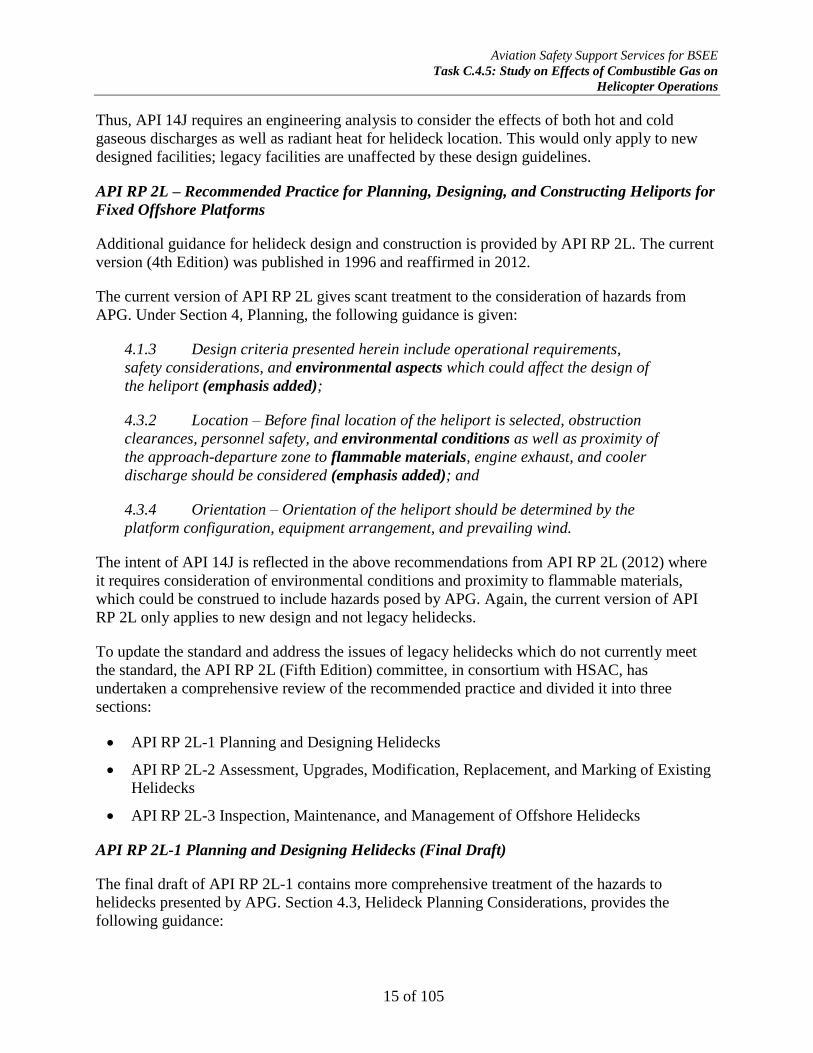
4.3.1 Location – Before the final location of the helideck is selected,
obstruction clearances, personnel safety, and environmental conditions, as well as
proximity of the obstacle free sector relative to flammable materials, hot and cold
gas discharges, flare or vent booms, and cooler discharges should be considered.
As illustrated in Figure 1, the helideck should be located to so that the TLOF and
associated flight paths are as far as possible outside the influence of the hot and
cold gas discharges (emphasis added).
Figure 1: Helideck Orientation Based on Wind Direction/Exhaust Discharges
4.8 Hot Air, Raw Gas, and Hydrogen Sulfide (H2S) Discharge
Raw gas discharges or hot air discharges from compressors and cooling systems
adjacent to helidecks may be hazardous to helicopter operations and can
drastically affect helicopter performance and appropriate restrictions should be
imposed on the use of the helideck where either of the above exists.
Hydrogen Sulfide (H2S) gas discharge in higher concentrations (300-500 ppm) can
cause loss of consciousness within a few seconds.
When designing helidecks that have been identified to have any of the above
conditions that may be hazardous to helicopter operations a visual warning system
should be provided to alert pilots of the hazard. See 4.4 for additional guidance on

Aviation Safety Support Services for BSEE
Task C.4.5: Study on Effects of Combustible Gas on
Helicopter Operations
17 of 105
wind tunnel testing and/or Computational Fluid Dynamics (CFD) and 7.4 for
status light guidance.
Sources of discharges should be located as far as practicable away from the
helideck, flight path, and oriented so the typical prevailing wind will carry the
discharges away from the helideck area (emphasis added).
Note – Sniffers (generic term used to describe automated vapor detection devices)
or other detection devices (infrared, etc.) may be used to detect these discharges
and to automatically activate status lights (see Section 7.4) when discharges may
present a hazard to flight operations.
This revision of the API RP 2L applies to new design helidecks only and provides that the
location of the helideck must take into consideration the hazards presented by APG (raw gases)
and that the sources of discharge (flare, pressure operated relieve valves (PORV) decks, etc.)
should be located as far as practicable from the helideck based on a computational fluid dynamic
(CFD) or other gas dispersion modeling study.
Mention is made of Section 9.2, Weather Measuring Equipment, which suggests, in addition to a
traditional wind sock directional indicator, that a manned facility for day VFR should be, as a
minimum, equipped with a weather station that provides wind speed and direction, gust spread,
temperature, barometric pressure, and a means to provide cloud ceiling height and prevailing
visibility. For facilities operating under night VFR or any IFR operations, the measurement
system must also provide the dew point value.
Where an existing manned facility is in close proximity to the planned new manned facility
(‘close’ as determined by the regulatory authority having jurisdiction) it may deemed that the
new facility does not have to provide the above equipment, provided those existing facilities
which are equipped can share their information routinely to the new facilities. For these new
facilities, a manual means of verifying and updating the visual elements of an observation, i.e.
cloud amount and height of base, visibility and present weather, may be used.
API RP 2L-2 Assessment, Upgrades, Modification, Replacement, and Marking of Existing
Helidecks (Draft)
The API RPL-2 draft concerning safety practices for legacy helidecks is in committee but is not
well defined. At the time of this writing, the section concerning hazards posed by flares has not
been addressed so is excluded from this report.
API RP 2L-3 Inspection, Maintenance, and Management of Offshore Helidecks (Draft)
A draft of this division of API RP 2L has not been completed. When drafted, it would be helpful
if recommendations of operational procedures promulgated by this report would be incorporated
in the operational guidance.
Aviation Safety Support Services for BSEE
Task C.4.5: Study on Effects of Combustible Gas on
Helicopter Operations
18 of 105
Helicopter Safety Advisory Conference (HSAC) Recommended Practice No. 92, Rev. 1 (2010):
Helicopter Safety, Gas Venting Helideck/Heliport Operational Hazard
Warning(s)/Procedures, Operations Near Gas Vent Booms
The HSAC RP No. 92 discusses the hazard presented by APG in very general terms:
Ignited flare booms can release a large volume of natural gas and create a hot
intense heat with little time for the pilot to react. Likewise, un-ignited gas vents can
release reasonably large volumes of methane gas under certain conditions. Thus,
operations conducted in close proximity to un-ignited gas vents require precautions
to prevent inadvertent ingestion of combustible gases by the helicopter engine(s).
The following is recommended.
1. Pilots
(a) Gas will drift upwards and downwind of the vent. Plan the approach and
takeoff to observe and avoid the area downwind or directly over the gas vent,
remaining as far away as practicable from the open end of the vent boom.
(b) Exercise caution when starting or landing on an offshore helideck when the
deck is downwind of a gas vent.
2. Oil Field Supervisors
(a) Notify nearby helicopter operators and bases of the hazard for planned
operations.
(b) Wind socks or indicator should be clearly visible to provide upward indication
for the pilot.
(c) High volume large gas vents should have red rotating beacons installed to
indicate when gas is venting.
International Regulations and Guidance
ICAO Annex 14 to the Convention on International Civil Aviation, Aerodromes, Section II,
Heliports
This international standard governs the construction and operation of aerodromes, including
heliports. Section 3.3, Helidecks, and Section 3.4, Shipborne Heliports, provide very general
guidance on the design of helidecks and refer the reader to the ICAO Heliport Manual for
detailed guidance.
The ICAO Heliport Manual, Document 9261-AN/903 (1995) references three principle types of
heliports: surface level, elevated, and helidecks which are located on offshore installations or
ships. The manual enlarges upon some of the specifications in Annex 14, Volume II, and also
provides additional guidance.
Aviation Safety Support Services for BSEE
Task C.4.5: Study on Effects of Combustible Gas on
Helicopter Operations
19 of 105
Section 1.4, Helidecks on Offshore Installations, advises that the location of the helideck is often
a compromise between conflicting demands of basic design requirements, space limitations, and
the process operational requirements of the installation. Statutory helideck design parameters
may not often be possible to meet, but necessary restrictions by the authority having jurisdiction
may be required, based upon tests such as metocean 14
data.
(“Where the statutory helideck design parameters cannot be fully met, it may be necessary for
restrictions to be imposed upon helicopter operations, based upon tests, for example in relation
to wind velocity.”) ICAO Heliport Manual, Document 9261-AN/903 (1995), 1.4.1.1.
Section 1.4.1.3 of the Heliport Manual provides some general guidance with respect to hazards
presented by APG:
The helideck should be so located that the required clear approach and takeoff
sector is available, making best use of the prevailing winds, and the FATO is least
affected by structure-induced turbulence or by high temperatures and turbulence
from the exhaust of gas turbines.
The combined effects of airflow direction and turbulence, prevailing wind, and
exhaust stack emissions should be determined for each installation and this
information should be made available to the helicopter operator.
Conversely, Section 1.4.3, Effects of Temperature Increases at Offshore Installations, gives
extensive treatment to the hazards associated with flares and gas plumes. It provides guidance on
hazard mitigation through design and location of the flare system:
1.4.3.2 Amongst the many effects of hot exhaust gases, one of the major aspects to
be considered is the resulting modification of helicopter performance. Sudden
increases in the environmental temperature over ambient can cause an abrupt loss
of engine and rotor performance at a most critical stage of the helicopter
operation.
1.4.3.3 The emission of exhaust gas is usually in the form of a number of
turbulent jets, which are injected into the complex turbulent flow that exists round
the installation. The result is an interaction process which produces great variation
in the rates of spreading and cooling individual plumes. The properties of the
temperature field can be measured by wind tunnel model testing. However, because
of the limited scope from a few scales of length, velocity and temperature, the
results achieved can be used only as a guide to the type of phenomena that can
exist in general, and to the relative levels of temperature that can be expected.
1.4.3.4 As a plume develops, with an origin relatively clear of the helideck, the
individual identity of the separate jets is gradually lost as the hot cloud mergers
into one plume. Accordingly, the temperature is reduced and is more evenly
14 Metocean: wind speed, direction, gustiness, wind rose, wind spectrum, air temperature, humidity
Aviation Safety Support Services for BSEE
Task C.4.5: Study on Effects of Combustible Gas on
Helicopter Operations
20 of 105
distributed. By elevating the outlets sufficiently, the helideck can be kept clear of
hot gas, but the resulting concentrated plume constitutes a considerable helicopter
hazard. By lowering the outlet positions into the separated flow around the
platform an increase in the dispersion of the plume can be obtained and the
centerline temperature can be markedly reduced. However, the spread of the
exhaust may become so great that almost all parts of the structure are
contaminated under some wind conditions. Quantitative tests thus become
necessary to access the acceptability of such a design (emphasis added).
1.4.3.5 Long, downward-directed outlets will remove most of the problems of
plume interference with helicopter operations and should be satisfactory for the
installation overall if suitable gas turbine and heating and ventilation intake
positions can be made available. Even so, it is always advisable to test a specific
configuration and associated gas turbine system with reference to particular
sensitive locations. It is stressed that, when doing so, consideration must be given
to the dynamic nature of the sensitive system, gas turbine intakes or the general
environment, so that due regard may be taken of the strong fluctuations in
temperature that may exist.
1.4.3.6 Helicopter performance may also be seriously impaired as a result of the
combined radiated and convected heat effects from flare plumes under certain wind
conditions. In moderate or stronger winds, the radiated heat is rapidly dissipated
and presents little problem for the helicopter pilot provided flight through the flare
plume is avoided. However, in calm or light wind conditions the changes in
temperature around the helideck can be very marked and localized and the
helicopter may undergo a sudden unexpected loss of performance just as it is about
to cross the edge of the helideck.
1.4.3.7 Designers should, therefore, exercise great care in the location and
elevation of flare towers in relation to helicopter operations (emphasis added).
The guidance presented above is relatively dated as it was published in 1995 before modern
computer-aided computational fluid dynamics (CFD) analysis was widely available as it is today.
The guidance is mainly related to increased thermal hazards from outflows of the gas turbine
compressors and power generation equipment but could be applicable to APG hazard mitigation
as well.
ISO 19901-2:2014 – Petroleum and natural gas industries — Specific requirements for
offshore structures — Part 3: Topsides structure
Section 9.5 provides guidance for helicopter landing facilities (helidecks). Section 9.5.1,
General, requires that environmental conditions around the helideck, particularly wind flow and
turbulence affected by adjacent structures, equipment and process plant, can influence the actions
on, and controllability of, helicopters during landing and take-off and shall be considered.
Conversely, Section 9.5.4, Reassessment of Existing Helidecks, allows for deviations from the
standard if approved by the authority having jurisdiction but does not address environmental
hazards, per se.

Aviation Safety Support Services for BSEE
Task C.4.5: Study on Effects of Combustible Gas on
Helicopter Operations
21 of 105
Conversely, Appendix A, Section A.9.5., Helicopter Landing Facilities (Helidecks) make
reference to ICAO Annex 14, Aerodromes, Volume II — Heliports, AN 14-2, as promulgating
the overall requirements for all aspects of helideck design, construction and equipment
applicable to certain jurisdictions. In other cases, the requirements are usually addressed in class
rules for floating or mobile structures such as the ABS Guide for the Class Notation Helicopter
Decks and Facilities (HELIDK and HELIDK(SRF)). Otherwise, ISO 19901 addresses only
structural consideration for helideck design.
Appendix A states that the selection of the platform layout should consider the effects of wind
turbulence from items near the helideck, such as accommodation blocks, turbine exhausts, cranes
and equipment. Thermal effects from hot and cold gases emitted by power generating or HVAC
plants on the platform should also be considered. Design methods to model these effects can
include wind tunnel (using small-scale physical models), or a CFD analysis.
UK Civil Aviation Authority (CAA) CAP 437 – Standards for Offshore Helicopter Landing
Areas (2013)
Under the Air Navigation Order (ANO), UK helicopter operators are responsible for ensuring
that helidecks to which they fly are ‘fit for purpose’. Installation and vessel owners, through their
Safety Management Systems (SMS), also have the responsibility for ensuring their helidecks
satisfy the helicopter operator’s requirements (CAP 437).
Section 2, Helideck Design Considerations – Environmental Effects, states:
The safety of helicopter flight operations can be seriously degraded by
environmental effects that may be present around installations or vessels and their
helidecks. The term “environmental effects” is used here to represent the effects of
the installation or vessel and/or its systems and/or processes on the surrounding
environment, which result in a degraded local environment in which the helicopter
is expected to operate. These environmental effects are typified by structure-
induced turbulence, turbulence and thermal effects caused by gas turbine exhausts,
thermal effects of flares and diesel exhaust emissions, and unburnt hydrocarbon
gas emissions from cold flaring or, more particularly, emergency blow-down
systems (emphasis added). It is almost inevitable that helidecks installed on the
cramped topsides of offshore installations will suffer to some degree from one or
more of these environmental effects, and controls in the form of operational
restrictions may be necessary in some cases (emphasis added). Such restrictions
can be minimized by careful attention to the design and layout of the installation
topsides and, in particular, the location of the helideck.
Section 2.2, Helideck Design Guidance, incorporates two publications: CAA Paper 99004 and
CAA Paper 2008/03, which are discussed below. Section 2.3.2 requires that all new-build
offshore helidecks, modifications to existing topside arrangements which could potentially have
an effect on the environmental conditions around an existing helideck, or helidecks where
operational experience has highlighted potential airflow problems should be subjected to

Aviation Safety Support Services for BSEE
Task C.4.5: Study on Effects of Combustible Gas on
Helicopter Operations
22 of 105
appropriate wind tunnel testing or Computational Fluid Dynamics (CFD) studies to establish the
wind environment in which helicopters will be expected to operate.
Section 2.3.4 discusses requirements for “some form of exhaust plume indication” to be provided
for use during helicopter operations. This visual indication system is associated with gas turbine
exhaust and is reported in CAA Paper 2007/02, which suggests that design consideration be
given to installation of an exhaust gas plume visualization system on installations having
significant gas turbine exhaust plume problems as determined by operational or CFD analysis.
The visualization system, such as injection of a “colored smoke” into the exhaust plume is used
to aid in visual detection and avoidance of the plume by the aircraft pilot. It should be
emphasized that this recommendation is not universal and is only suggested for installations that
have identified plume-helideck operational issues.
Section 2.3.5 discusses that hazard of APG. While not providing guidance on the location of the
flare exhaust, it discusses operational limitations during cold flaring of APG:
The maximum permissible concentration of hydrocarbon gas within the helicopter
operating area is 10% Lower Flammable Limit (LFL). Concentrations above 10%
LFL have the potential to cause helicopter engines to surge and/or flame out with
the consequent risk to the helicopter and its passengers. It should also be
appreciated that, in forming a potential source of ignition for flammable gas, the
helicopter can pose a risk to the installation itself. It is considered unlikely that
routine ‘cold flaring’ will present any significant risk, but the operation of
emergency blow-down systems should be assumed to result in excessive gas
concentrations. Installation operators should have in place a management system
which ensures that all helicopters in the vicinity of any such releases are
immediately advised to stay clear.
The limitation concerning the maximum permissible APG concentration is discussed below. It is
unclear from any of the documentation associated with CAP 437 as to how the statement “it is
considered unlikely that routine ‘cold flaring’ will present any significant risk” was derived and
there appears no engineering or scientific basis formally referenced for this statement in any
supporting documentation for CAP 437.
Mention is made of Chapter 6, Helicopter Landing Areas – Miscellaneous Operational
Standards, Section 4.2, Meteorological Observations, which strongly recommends that
installations be provided with a means of providing meteorological data to the helicopter pilot,
including wind speed and direction, air temperature and dew point, barometric pressure, cloud
coverage and base height, and prevailing visibility.
UK CAA Paper 99004 – Research on Helideck Environmental Issues (2000)
This paper was a joint project between the CAA and the UK Health & Safety Executive (HSE)
and focused on environmental hazards to helidecks. The prime contractor for the paper was BMT
Fluid Mechanics, Limited. In 1995, an accident occurred on the Claymore Accommodation
Platform which, although it did not involve any fatalities or serious injuries, highlighted the need
to reassess the environmental hazards to helicopters operating in close proximity to offshore

Aviation Safety Support Services for BSEE
Task C.4.5: Study on Effects of Combustible Gas on
Helicopter Operations
23 of 105
installations. The features of the accident gave rise to concern related to an uncontrollable
descent immediately above the landing area, resulting in a heavy [hard] landing and extensive
damage to the helicopter. The precise cause was not determined, but it was most probable that
the flying pilot inadvertently flew into a plume of combustion products from a gas turbine unit
operating on the bridge-linked production platform. As a result of this mishap and others, the UK
CAA and HSE commissioned the study on environmental hazards to offshore helicopter
operations which promulgated the findings and recommendations in CAA Paper 99004 and its
progeny, CAA Paper 2008/03 and as incorporated in CAP 437.
While CAA Paper 99004 addresses mainly mechanical wind turbulence and hot exhaust gas
temperature plumes which may cause adverse effects in the flying qualities and engine
performance, respectively, it does provide some guidance concerning the hazard from APG:
4.1.5 Release of Process Gas
There are occasions in the operating life of a platform when gas from the
process streams will be vented to atmosphere. Accidental releases may also occur.
The aerodynamic behavior of the released gas will depend upon its density,
temperature, venting momentum and location on the platform.
Clearly, these are circumstances requiring extreme caution for all platform
operations since the release offers the potential for fire or explosion. That said, the
extent of flammable/explosive conditions are often defined during the Safety Case
process and the principles of entrainment of air and dilution are analogous to that
for hot plumes. Away from the immediate area of the source the resulting plume or
cloud will be carried in the direction of, and with the speed of, the local wind. The
hazard due to the ingestion of hydrocarbon gas mixtures into a helicopter engine is
discussed in Section 5.3.
4.1.6 Flared Gas
Platforms normally have flare towers, comprising tall or long cantilevered
structures designed to remove a source of released gas as far away from the
platform as is practicable. The flare may also be the location for the venting of
unburned gas (see Section 4.1.5), but, specifically, it is designed to burn off excess
gas. The Energy Act of 1985 calls for gas conservation so that flaring is essentially
for use only in the event of an emergency. (Note – this is not true on the U.S. OCS).
Flares are, of course, highly visible, though the thermal plume beyond the flame
is not. The combustion products beyond the flame tip are hot (many hundreds of
degrees C), but the process of mixing and cooling is aggressive and the plume
dilutes and cools whilst moving downwind much like any other turbulent plume.
The hot gas plume from the flare presents a hazard similar to the gas turbine
exhausts plume, but it has the advantage of usually being more visible to pilots.
Aviation Safety Support Services for BSEE
Task C.4.5: Study on Effects of Combustible Gas on
Helicopter Operations
24 of 105
One reason for the flare tip to be well removed from the platform is to avoid
radiant heat from the flame affecting personnel, equipment and the helideck. This is
considered and dealt with during the platform design phase.
Concerning guidance on location of the flare or emergency blowdown system from
the helideck, Section 4.2.4 and 4.2.5 discuss this in general terms:
4.2.4 Flare Location
The flare tower (vertical structure) or flare boom (inclined lattice structure) is
designed to remove the flare tip a sufficient distance from the platform to ensure
that the radiated heat from the flame is not a problem on the platform itself. The
flare boom is located at the process end of the platform and the initial design
requirement is to keep temperatures at acceptable levels in the associated working
areas. The helideck is, necessarily, considerably more distant from the flare and
special considerations for radiant heat should not be required.
As far as the hot plume emitted by the flame is concerned, it will generally be at
sufficient elevation to be well clear of the helideck. During approach and take-off,
if the flare is alight the plume alignment will be downwind of the tip and generally
higher. The plume may thus be avoidable by exercising precautions in flight,
supported by information on flare plume characteristics derived at the design
assessment stage.
From the standpoint of design, per se, relatively little can be done to make the
flare more helicopter friendly (emphasis added).
4.2.5 Gas Blow-Down Systems
In the event of process upset, there may be an operational requirement to
discharge hydrocarbons to the atmosphere. Generally it will be preferable to burn
the released gas in a controlled fashion and so the blow-down system is led to the
flare boom.
Significant gas releases are fortunately rare events, with just 16 major releases
reported in 1996/97 under the Reporting of Injuries, Diseases and Dangerous
Occurrences Regulations 1995. If the discharged gases are released unburned
then a significant hazard of mixtures which are potentially flammable can exist.
From the standpoint of helicopter operations, this is a situation which can only
be avoided by information and communication with the platform (emphasis
added). Such procedures should logically form part of the platform operational
Safety Case.
Aviation Safety Support Services for BSEE
Task C.4.5: Study on Effects of Combustible Gas on
Helicopter Operations
25 of 105
UK CAA Paper 2008/03 – Helideck Design Considerations – Environmental Effects (2009)
Although both CAA Paper 99004 and 2008/03 are incorporated by reference in CAP 437, the
latter is an update of the former and gives specific treatment to location of flare vents and
hazards presented by APG:
3.7 Cold Flaring and Rapid Blow-Down Systems
Hydrocarbon gas can be released from the production platform process or from
drilling rigs at various times. It is important to ensure that a helicopter cannot fly
into a cloud of hydrocarbon gas because;
• concentrations above 10% of Lower Flammable Limit (LFL) might cause the
helicopter engine to surge or flameout with consequent risk to the helicopter,
and
• the helicopter poses a risk to the offshore installation because it is a
potential ignition source for the hydrocarbon gas.
Consideration therefore needs to be given to ensuring that gas release points
are as remote as possible from the helideck and helicopter flight path, and that
any unforeseen gas releases activate the helideck status lights (flashing red).
Planned gas releases should only occur when helicopters are not in the area
(emphasis added).
The blow-down system on a production platform depressurizes the process
system releasing the hydrocarbon gas. It will normally be designed to reduce the
pressure to half, or to 7 bar, in 15 minutes (the API standard). For a large offshore
installation this might require the release of 50 tonnes of gas or more. Once down
to this target pressure in 15 minutes or less, the remainder of the gas will continue
to be released from the system. A blow-down may be automatically triggered by the
detection of a dangerous condition in the production process. Alternatively it may
be triggered manually. The blow-down system should have venting points that are
as remote as possible from the helideck and, in prevailing winds, downwind of the
helideck. It is common to have this vent on the flare boom, and this will normally
be a good location.
However, it should be noted that dilution of the gas to 10% LFL may not
occur until the plume is a considerable distance from the venting point. This
distance could be anywhere between 200m – 500m depending on vent size,
venting rate and wind speed (emphasis added).
Drilling rigs often have 'poor-boy degassers' which are used to release gas
while circulating a well, but a drilling rig is unlikely to release any significant
quantities of gas without warning, unless there is a sudden major crisis such as a
blow-out. As with production platforms, it is unlikely to be possible to locate the
helideck sufficiently distant from the potential gas sources to guarantee 10%

Aviation Safety Support Services for BSEE
Task C.4.5: Study on Effects of Combustible Gas on
Helicopter Operations
26 of 105
LFL or less, (emphasis added) and so the rig should not accept helicopter flights
when well circulation activity is going on, or when there are problems down the
well. Helideck status lights should be connected to the appropriate gas detection
systems and automatically initiated (emphasis added).
Discussion on the 10% lower flammability limits (LFL) is presented below on the section on
methane ingestion effects on helicopter turboshaft engines.
Lastly, Section 3.9, Multiple Platform Configurations, requires the consideration of the effects of
adjacent facilities, whether they are interconnected or not, on aerodynamics, hot gasses, etc., on
the other platform’s helideck.
UK HSE Helideck Design Guideline (No Date)
As a supplement to the CAA CAP 437 regulations, the UK Health & Safety Executive (HSE) has
issued a helideck design guideline. Recommendation 10.3 (i) in CAA Paper 99004 discussed
above was the main starting point for the guidelines along with an increasing number of non-
conformities found during helideck inspections.
The helideck design guidelines are designed to be used in conjunction with the latest edition of
CAP 437 and the UK Offshore Operators Association Guidelines for Management of Offshore
Helideck Operations which are considered companion documents.
Section 10.4.6, Temperature Rise Due to Hot Exhausts, recommends against the long,
downward-directed outlets for gas turbine exhaust gases (and by extension, APG discharges)
promulgated by Section 1.4.3.5 of ICAO Annex 14, Volume II. The helideck design guide states:
For certain wind directions the hot gas plumes from the exhausts will be carried by
the wind directly across the helideck. The hot gas plume mixes with the ambient air
and the mixing increases the size of the plume, and reduces the temperature (by
dilution).
In the past, some platforms were fitted with downward facing exhausts so that the
hot exhaust gases were initially directed down towards the sea surface. This
arrangement is not recommended because the hot plume can rise and disperse in
an unpredictable way, particularly in light wind conditions (emphasis added).
Concerning hazards from APG flares and emergency blowdown systems, the helideck design
guidelines incorporated verbatim Section 3.7, Cold Flaring and Rapid Blow-Down Systems, of
CAA Paper 2008/03 discussed above.
NORSOK C004 Ed. 2 – Helicopter Decks on Offshore Installations (2015)
The NORSOK standards are developed by the Norwegian petroleum industry to ensure adequate
safety, value adding and cost effectiveness for petroleum industry developments and operations.
Furthermore, NORSOK standards are as far as possible intended to replace oil company
specifications and serve as references in the authorities’ regulations.

Aviation Safety Support Services for BSEE
Task C.4.5: Study on Effects of Combustible Gas on
Helicopter Operations
27 of 105
The NORSOK helideck standard is based on practical experiences accumulated from helicopter
operations on the Norwegian continental shelf. Relevant information was provided by oil
companies, helicopter operators, and The Foundation for Scientific and Industrial Research at
The Norwegian University of Science and Technology (SINTEF). A joint industry project on
helideck safety was completed in January 2000. The main conclusions and recommendations are
included in NORSOK C004 and the standard focuses on a rational selection of design criteria
and other measures, to increase safety and flight regularity in connection with offshore helicopter
deck operations.15
Section 5.1 requires a CFD analysis or wind tunnel test to be performed for initial design and for
any substantial modifications to the helideck. Any conclusions or recommendations shall verify
and document that the helideck has been given an optimal location on the offshore installation.
Any possible hazards or restrictions on helicopter operations are to be identified.
Section 5.4 provides guidance on the mitigation of hot gas turbulence with respect to flare and
gas turbine exhaust outflow but not to APG specifically:
Offshore installations will normally contain a variety of systems and processes that
will emit hot air flows, typically generated by turbine generators, diesel engines
and flare(s). Hot air flows from these systems may create turbulence and other
thermal effects that may severely affect helicopter operations, unless adequate risk
reducing measures are taken at the design stage.
Hot air flow, combined with a sudden change in air temperature, may have the
following two major effects on the helicopter performance:
possible momentary stalling of helicopter engines due to sudden air density changes
through the turbine compressors;
significant reduced helicopter lift capacity.
These risks can be controlled by either proper design, which should be the main
priority, or by operational measures that may involve certain helicopter flight
limitations [emphasis added]. The risk varies with helicopter type, and the risk
level increases with large temperature gradients in the flight path.
The standard gives three methods for determining the risk of thermal gradients to helicopter
operations. Method 1 requires a CFD analysis for designing new helidecks and requires that the
free airspace above the helideck not be exposed to a temperature increase of more than 2°C (iso-
contour from the CFD). The free airspace is defined as a height above the helideck
corresponding to approximately 10 meters (33 feet) plus the skid or wheels-to-rotor height plus
one rotor diameter. In situations where Method 1 is deemed impossible, unpractical or
15 NORSOK standard C-004, Helicopter deck on offshore installations, Rev. 2, May 2015;
http://www.standard.no/pagefiles/1323/c-004.pdf
Aviation Safety Support Services for BSEE
Task C.4.5: Study on Effects of Combustible Gas on
Helicopter Operations
28 of 105
noncompliant, two other methods are provided. Method 2 is empirically derived and bases on a
plot of minimum height of gas release versus distance from the center of the helideck.
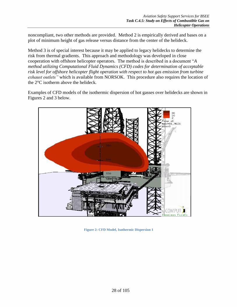
Method 3 is of special interest because it may be applied to legacy helidecks to determine the
risk from thermal gradients. This approach and methodology was developed in close
cooperation with offshore helicopter operators. The method is described in a document “A
method utilizing Computational Fluid Dynamics (CFD) codes for determination of acceptable
risk level for offshore helicopter flight operation with respect to hot gas emission from turbine
exhaust outlets” which is available from NORSOK. This procedure also requires the location of
the 2°C isotherm above the helideck.
Examples of CFD models of the isothermic dispersion of hot gasses over helidecks are shown in
Figures 2 and 3 below.
Figure 2: CFD Model, Isothermic Dispersion 1

Aviation Safety Support Services for BSEE
Task C.4.5: Study on Effects of Combustible Gas on
Helicopter Operations
29 of 105
Section 5.5, Hydrocarbon gas emission, is a new section not included in the first edition of the
standard (2004):
Cold flares and emergency blow down (sic) systems are a potential source of hazard that
helideck designers should be aware of. Concentration of hydrocarbon gas in the helicopter
operational environment may be a potential danger to both the helicopter and the offshore
installation. The helicopter itself may be a potential ignition source endangering the
offshore installation; while a hydrocarbon concentration above 10% low flammability
limit (LFL) may cause engine surge and flameout endangering the helicopter [emphasis
added]. Helicopter operations will be immediately stopped should such conditions occur.
While the language of Section 5.5 is an improvement over the previous version in that it
recognizes the hazard to flight operations posed by APG, it does not give any guidance on how
“helicopter operations will be immediately stopped” if the gas concentration over the helideck
should reach the 10 percent LFL limit. This mandate would require a CFD gas dispersion model
of the facility at the least favorable wind conditions (Figure 4) to quantify the risk, and that point
and area gas detection equipment be installed to provide the operator warning of the hazardous
conditions in time to alert the flight crew prior to approach or departure. Examples of CFD gas
dispersion models are shown in Figures 5-7 below.
Figure 3: CFD Model, Isothermic Dispersion 2
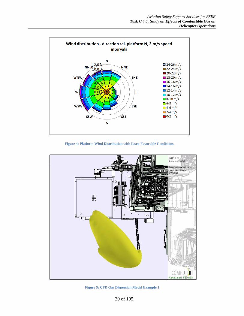
Aviation Safety Support Services for BSEE
Task C.4.5: Study on Effects of Combustible Gas on
Helicopter Operations
30 of 105
Figure 4: Platform Wind Distribution with Least Favorable Conditions
Figure 5: CFD Gas Dispersion Model Example 1
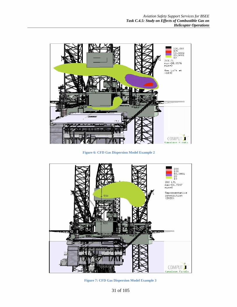
Aviation Safety Support Services for BSEE
Task C.4.5: Study on Effects of Combustible Gas on
Helicopter Operations
31 of 105
Figure 6: CFD Gas Dispersion Model Example 2
Figure 7: CFD Gas Dispersion Model Example 3
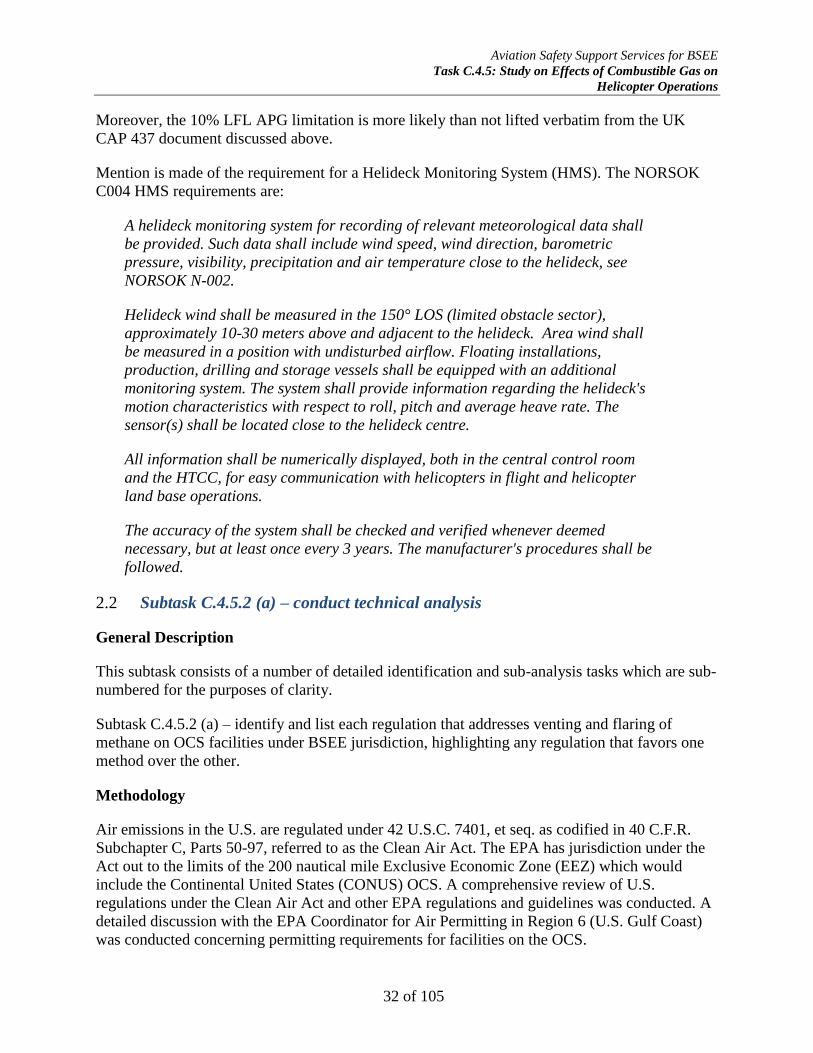
Aviation Safety Support Services for BSEE
Task C.4.5: Study on Effects of Combustible Gas on
Helicopter Operations
32 of 105
Moreover, the 10% LFL APG limitation is more likely than not lifted verbatim from the UK
CAP 437 document discussed above.
Mention is made of the requirement for a Helideck Monitoring System (HMS). The NORSOK
C004 HMS requirements are:
A helideck monitoring system for recording of relevant meteorological data shall
be provided. Such data shall include wind speed, wind direction, barometric
pressure, visibility, precipitation and air temperature close to the helideck, see
NORSOK N-002.
Helideck wind shall be measured in the 150° LOS (limited obstacle sector),
approximately 10-30 meters above and adjacent to the helideck. Area wind shall
be measured in a position with undisturbed airflow. Floating installations,
production, drilling and storage vessels shall be equipped with an additional
monitoring system. The system shall provide information regarding the helideck's
motion characteristics with respect to roll, pitch and average heave rate. The
sensor(s) shall be located close to the helideck centre.
All information shall be numerically displayed, both in the central control room
and the HTCC, for easy communication with helicopters in flight and helicopter
land base operations.
The accuracy of the system shall be checked and verified whenever deemed
necessary, but at least once every 3 years. The manufacturer's procedures shall be
followed.
Subtask C.4.5.2 (a) – conduct technical analysis 2.2
General Description
This subtask consists of a number of detailed identification and sub-analysis tasks which are sub-
numbered for the purposes of clarity.
Subtask C.4.5.2 (a) – identify and list each regulation that addresses venting and flaring of
methane on OCS facilities under BSEE jurisdiction, highlighting any regulation that favors one
method over the other.
Methodology
Air emissions in the U.S. are regulated under 42 U.S.C. 7401, et seq. as codified in 40 C.F.R.
Subchapter C, Parts 50-97, referred to as the Clean Air Act. The EPA has jurisdiction under the
Act out to the limits of the 200 nautical mile Exclusive Economic Zone (EEZ) which would
include the Continental United States (CONUS) OCS. A comprehensive review of U.S.
regulations under the Clean Air Act and other EPA regulations and guidelines was conducted. A
detailed discussion with the EPA Coordinator for Air Permitting in Region 6 (U.S. Gulf Coast)
was conducted concerning permitting requirements for facilities on the OCS.
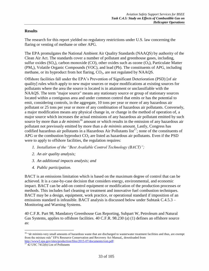
Aviation Safety Support Services for BSEE
Task C.4.5: Study on Effects of Combustible Gas on
Helicopter Operations
33 of 105
Results
The research for this report yielded no regulatory restrictions under U.S. law concerning the
flaring or venting of methane or other APG.
The EPA promulgates the National Ambient Air Quality Standards (NAAQS) by authority of the
Clean Air Act. The standards cover a number of pollutant and greenhouse gases, including,
sulfur oxides (SOx), carbon monoxide (CO), other oxides such as ozone (O3), Particulate Matter
(PMx), Volatile Organic Compounds (VOC), and lead (Pb). The constituents of APG, including
methane, or its byproduct from hot flaring, CO2, are not regulated by NAAQS.
Offshore facilities fall under the EPA’s Prevention of Significant Deterioration (PSD) [of air
quality] rules which apply to new major sources or major modifications at existing sources for
pollutants where the area the source is located is in attainment or unclassifiable with the
NAAQS. The term "major source" means any stationary source or group of stationary sources
located within a contiguous area and under common control that emits or has the potential to
emit, considering controls, in the aggregate, 10 tons per year or more of any hazardous air
pollutant or 25 tons per year or more of any combination of hazardous air pollutants. Conversely,
a major modification means any physical change in, or change in the method of operation of, a
major source which increases the actual emissions of any hazardous air pollutant emitted by such
source by more than a de minimis16
amount or which results in the emission of any hazardous air
pollutant not previously emitted by more than a de minimis amount. Lastly, Congress has
codified hazardous air pollutants in a Hazardous Air Pollutants list17
; none of the constituents of
APG or the combustion byproduct CO2 are listed as hazardous air pollutants. Even if the PSD
were to apply to offshore facilities, the regulation requires:
1. Installation of the “Best Available Control Technology (BACT)”;
2. An air quality analysis;
3. An additional impacts analysis; and
4. Public participation.
BACT is an emissions limitation which is based on the maximum degree of control that can be
achieved. It is a case-by-case decision that considers energy, environmental, and economic
impact. BACT can be add-on control equipment or modification of the production processes or
methods. This includes fuel cleaning or treatment and innovative fuel combustion techniques.
BACT may be a design, equipment, work practice, or operational standard if imposition of an
emissions standard is infeasible. BACT analysis is discussed below under Subtask C.4.5.3 –
Monitoring and Warning Systems.
40 C.F.R. Part 98, Mandatory Greenhouse Gas Reporting, Subpart W, Petroleum and Natural
Gas Systems, applies to offshore facilities. 40 C.F.R. 98.230 (a) (1) defines an offshore source
as:
16 “de minimis-very small amounts of hazardous waste that are discharged to wasterwater treatment facilities and thus, are exempt
from the mixture rule” EPA Resource Conservation and Recovery Act Manual,, downloaded from
http://www2.epa.gov/sites/production/files/2015-07/documents/rom.pdf: 17 42 USC 7412(b) List of Pollutants

Aviation Safety Support Services for BSEE
Task C.4.5: Study on Effects of Combustible Gas on
Helicopter Operations
34 of 105
Offshore petroleum and natural gas production is any platform structure, affixed
temporarily or permanently to offshore submerged lands, that houses equipment to
extract hydrocarbons from the ocean or lake floor and that processes and/or
transfers such hydrocarbons to storage, transport vessels, or onshore. In addition,
offshore production includes secondary platform structures connected to the
platform structure via walkways, storage tanks associated with the platform
structure and floating production and storage offloading equipment (FPSO). This
source category does not include reporting of emissions from offshore drilling and
exploration that is not conducted on production platforms;
MODU’s are generally exempt from the reporting requirements.
40 C.F.R. § 98.231, Reporting Threshold, section (b) requires offshore petroleum and natural gas
production facilities to report carbon dioxide (CO2), methane (CH4), and nitrous oxide (N2O)
emissions from equipment leaks, vented emission, and flare emission source types as identified
in the data collection and emissions estimation study conducted by the Bureau of Ocean Energy
Management, Regulation, and Enforcement (BOEMRE18
) in compliance with 30 C.F.R.
§250.302 through 304. Offshore platforms do not need to report portable emissions. The current
(2014) 30 C.F.R. §250 does not contain sections 250.302 through 304.
Subtask C.4.5.2 (b) – identify and list each helicopter (make, model, and engine) 2.3
used on OCS facilities under BSEE jurisdiction.
Methodology
An internet search of helicopter companies operating under 14 C.F.R, Part 135 generally
engaged in offshore oil and gas exploration and production was made to determine the
representative makes and models of helicopters operating on the OCS. Moreover, the experience
of the aviation safety analysts with extensive experience in offshore helicopter operations was
used.
Results
There were seven (7) major airframe manufacturers producing 56 different models and their
variants. Conversely, five (5) engine manufacturers were identified which were producing 41
turboshaft engine models and their variants.
A complete listing of make, model, engine(s) and specifications, including shaft horsepower,
maximum gross takeoff weight (MGTOW), range, and crew and passenger capacities is provided
in Appendix E.
18 The Bureau of Ocean Energy Management, Regulation and Enforcement (BOEMRE.) was replaced by the Bureau of Safety
and Environmental Enforcement (BSEE) on October 1, 2011 as part of a major reorganization of the Department of the Interior's
offshore regulatory structure.

Aviation Safety Support Services for BSEE
Task C.4.5: Study on Effects of Combustible Gas on
Helicopter Operations
35 of 105
Subtask C.4.5.2 (c) – (1) determine the vapor density for each flammable gas 2.4
(lighter or heavier than air) to determine how the placement of vents would
affect helicopter operations; and (2) determine the flammability limits for each
flammable gas to determine the effect on helicopter operations.
Methodology
A byproduct of offshore hydrocarbon production and processing is associated petroleum gas
(APG). APG is a form of natural gas which is found in geophysical hydrocarbon deposits, either
dissolved in the liquid hydrocarbons or as a free gas above the liquid in the reservoir. For safety
reasons, offshore installations are equipped with a flare boom or stack to perform a controlled
release of APG into the atmosphere (known as “venting” or “cold flaring”) or to perform a
controlled burn of the APG (known as “flaring”), if any or all of the APG constituent gasses
cannot be recovered or recycled for economic or practical reasons. During flaring, the APG are
combined with steam and/or air, and burnt off in the flare system to produce water vapor and
carbon dioxide which produces a visible flame and forms a non-explosive vapor cloud. If the
flare is not ignited (cold flaring), the APG forms an invisible vapor cloud which may be
flammable, depending upon its stoichiometric concentration with the air.
Most process facilities either use APG as a fuel gas for compressor turbines, electrical power
generation, or other utilities, or attempt to separate APG into its constituent gases as an economic
product and to reduce their potential to emit pollutants as part of an air quality program. The
APG is separated from the liquid hydrocarbons through flash or phase separation, then extracted
through a fractionation train using a deethanizer, depropanizer, and debutanizer, leaving methane
as the last constituent gas of the APG. If this methane is not used as a fuel gas, it is sent to the
off-gas incinerator (flare). Therefore, methane makes up more than 90 percent of the APG
released by the flare system. Figures 8 and 9 represent the APG elimination process.
Since methane makes up the bulk of APG, to simplify the analysis, only methane need be
considered as a combustible gas hazard to rotorcraft.
Physical data for the constituents of APG was found in the Chemistry Handbook published by
the National Institute for Standards and Technology (NIST) Materials Measurement Laboratory.

Aviation Safety Support Services for BSEE
Task C.4.5: Study on Effects of Combustible Gas on
Helicopter Operations
36 of 105
Figure 8: APG Dethanization Process
Figure 9: Off-Gas Incinerator Process (Flare)

Aviation Safety Support Services for BSEE
Task C.4.5: Study on Effects of Combustible Gas on
Helicopter Operations
37 of 105
Results
Table 1 presents the hydrocarbon constituents of APG and their associated physical properties.
APPOXIMATE APG COMPOSITION AND PHYSICAL PROPERTIES
Common Name
Molecular Formula
Volume Fraction (% APG)
Molar Mass
(g-mol-1
)
Flammability Limits (%Vol)
Boiling Point (°C)
Autoignition Temperature
(°C)
High Heat Value
(kJ-mol-1
)
Ignition Energy
(mJ)
Methane CH4 81.0 16 4.4-17 -161.5 537 889 0.21
Ethane C2H6 5.5 30 2.9-13 -88.5 472 1,560 0.22
Propane C3H8 6.6 44 2.4-9.5 -42.2 540 2,220 0.26
Butane C4H10 4.0* 58 1.8-8.4 -1.0 288 2,877 0.25
Isobutane C4H10 4.0* 58 1.4-8.3 -13.0 460 2,877 0.26
Pentane C5H12 1.4* 72 1.4-8.3 35.9 260 3,507 0.24
Isopentane C5H12 1.4* 72 1.4-8.3 27.8 420 3,507 0.21
Hydrogen Sulfide H2S Variable 34 4.3-46 -60.4 232 512 0.068
Table 1: Approximate APG Composition and Physical Properties
In general, the combustible gases of concern are the C1 through C5 series hydrocarbons and their
common isomers which are normally flammable gases at atmospheric standard temperatures and
pressures. Pentane is usually a small constituent of APG but is a flammable gas at flare stack
temperatures. The common name of the compound is the one generally used and understood in
the offshore industry as opposed to the International Union for Pure and Applied Chemistry
(IUPAC) name; for example, the IUPAC name for water is dihydrogen monoxide and
methylpropane for isobutane.
The molar mass (gram molecular mass) is the weight of one molecule of the compound
determined by summing the molecular mass of each constituent atom. The flammability limits
are the upper and lower concentrations in normoxic air at 25°C at which the compound would
ignite and or explode when exposed to a competent ignition source, such as a flame or spark. The
boiling point is the temperature at which the vapor pressure of the liquid equals the atmospheric
pressure surrounding the liquid and the liquid changes into a vapor. At any temperature above
the boiling point, the compound is a gas. The autoignition temperature is the lowest temperature
at which the compound will spontaneously ignite in normoxic air without a competent ignition
source. This temperature is required to supply the activation energy needed for combustion
through adiabatic heating such as compression in a turboshaft engine. The high heat value is the
theoretical specific energy content of the compound that would be released on combustion.
Lastly, the minimum ignition energy (MIE) is the minimum amount of energy required to ignite
a flammable vapor or gas cloud, such as by an electrostatic discharge.
For hydrocarbons C1 to C5, there is a direct relationship between the gram molecular weight and
the boiling point and heat energy values. Conversely, there is an inverse relationship between the
gram molecular weight and the flammability limits and autoignition temperature. This is a
predictable result from the hydrogen bond energy on the carbon atoms which is well known in
Aviation Safety Support Services for BSEE
Task C.4.5: Study on Effects of Combustible Gas on
Helicopter Operations
38 of 105
hydrocarbon reactions. Note that isomers can affect a large increase in the autoignition
temperature of the compound.
Air has an average gram molecular weight of 29 g-mol-1
at standard temperature and pressure.
Thus, any compound with a molar weight larger than this value will be heavier than air.
Methane, with a value of 16 g-mol-1
is the only compound lighter than air and thus has
profound consequences when considering the effects of turboshaft hydrocarbon gas
ingestion.
The average minimum ignition energy (MIE) for APG is approximately 0.25 millijoules (mJ).
This is extremely small ignition energy. For example, the static electricity generated by a person
walking across an electrostatically-charged carpet is about 10 mJ or about 40 times the ignition
energy required to ignite APG vapors. Thus, even the static electricity generated by a helicopter
rotor is sufficient to ignite an APG vapor cloud. Therefore, if the aircraft were to fly into an APG
vapor cloud between its upper and lower flammability limits, a flash fire or vapor cloud
explosion (VCE) would occur, resulting in destruction of the aircraft and substantial damage or
loss of the installation.
Mention is made of hydrogen sulfide (H2S) which may be a constituent of “sour” APG. Sour gas
is APG containing more than 5.7 mg-m-3
H2S, which is equivalent to 4 ppm by volume at
standard temperature and pressure. H2S is a highly toxic and flammable gas of great concern in
hydrocarbon processing. It has wide flammability limits of between 4.3 to 46 percent by volume
of air of which it is heavier. Because of its extreme toxicity, comparable to hydrogen cyanide, it
is scrubbed from sour gas processes by use of highly efficient amine treating systems. For
example, inhalation of a single breath of H2S at or above 1,000 ppm results in immediate
collapse and respiratory arrest from cellular hypoxia at the mitochondrial level; 1,000 ppm is 0.1
percent by volume. Thus, H2S does not represent an engine ingestion hazard to helicopter
operations in the way that C1 through C5 hydrocarbons do.
Subtask C.4.5.2 (d) – (1) determine the concentration parameters for each 2.5
flammable gas to determine the effect on helicopter operations
Methodology
The concentration parameters for APG are combined with and discussed in Subtask C.4.5.2 (e),
below.
Each of the helicopter engine manufacturers was contacted and asked if there was any specific
operational limitation on the percentage of methane by volume. The FAA Type Certificate Data
Sheet for each engine make and model was also consulted as well as operation and maintenance
manuals.
Results
As discussed above in Subtask C.4.5.1 – Review and Assess Helideck Construction Standards,
CAP 437 Section 2.3.5 states the maximum permissible concentration of hydrocarbon gas within
the helicopter operating area is 10 percent of the lower flammable limit (LFL). Concentrations

Aviation Safety Support Services for BSEE
Task C.4.5: Study on Effects of Combustible Gas on
Helicopter Operations
39 of 105
above 10 percent LFL have the potential to cause helicopter engines to surge and/or flameout
with the consequent risk to the helicopter and its passengers. CAP 437 considered it unlikely that
routine cold flaring would present any significant risk, but it was unclear on how that conclusion
was reached. This 10 percent of LFL was based on CAA Paper 2008/03 and 99004 discussed
above. The root paper, 99004, stated that this could not be determined without detailed study on
the effects of hydrocarbon gas ingestion on turboshaft engines. This limitation is discussed
further in Subtask C.4.5.2 (e) below.
The engine manufacturers contacted were Safran Turbomeca, Rolls-Royce/Allison, Pratt &
Whitney, Lycoming Textron, and General Electric. Responses were received from Turbomeca,
Rolls-Royce, and Lycoming. Turbomeca and Lycoming did not have an operating limitation for
methane but it was unclear if this had actually been studied by the manufacturer. The FAA
TCDS for the Turbomeca engines stated that the engines have not been tested to evaluate the
effects of foreign object ingestion other than rain water. Rolls-Royce provided a copy of
Customer Service Letter CSL-1230, dated 19 September 2001, which states:
Rolls-Royce has reviewed a recent inquiry regarding an acceptable level of methane gas for the
operating environment of Model 250 engines. This information is considered valuable to all
Model 250 operators who may operate in or near known atmospheric conditions which may
contain levels of methane gas.
Rolls-Royce recommends a maximum methane/air mixture of 3% methane by volume. This level
will minimize the risk of methane igniting inside the engine, outside of the combustion area. It is
also recommended to avoid incursions with known methane gas by flying upwind and above the
methane laden areas if possible.19,
20
Subtask C.4.5.2 (d) – (2) specifically identify if each helicopter engine 2.6
manufacturer has a known percentage of methane (or other combustible gas) to
volume that is hazardous to engine operations.
Methodology
The concentration parameters for APG are combined with and discussed in Subtask C.4.5.2 (e),
below.
Each of the helicopter engine manufacturers were contacted and asked if there was any specific
operational limitation on the percentage of methane by volume. The FAA Type Certificate Data
Sheet (TCDS) for each engine make and model were also consulted as well as operation and
maintenance manuals.
The FAA and NTSB were contacted and asked if there had been any research on APG ingestion.
They provided no data or information regarding the question.21
19 Rolls-Royce Commercial Service Letter “Operations in Methane Laden Atmosphere”, September 19, 2001 20 Rolls-Royce was contacted and asked for engineering data to support the 3% methane limitation, but the OEM declined to
provide any technical basis for the recommendation or participate in the methane ingestion study. 21 Telephonic conversation with Jorge Fernandez, FAA Engine Certification Office (ANE-14), April 17, 2015

Aviation Safety Support Services for BSEE
Task C.4.5: Study on Effects of Combustible Gas on
Helicopter Operations
40 of 105
Results
As discussed above in Subtask C.4.5.1 – Review and Assess Helideck Construction Standards,
CAP 437 Section 2.3.5 states the maximum permissible concentration of hydrocarbon gas within
the helicopter operating area is 10 percent of the lower flammable limit (LFL). The LFL for
methane is 4.4 percent by volume; thus 10 percent LFL for methane is 0.44 percent.
Concentrations above 10 percent LFL have the potential to cause helicopter engines to surge
and/or flameout with the consequent risk to the helicopter and its passengers. CAP 437
considered it unlikely that routine cold flaring would present any significant risk, but it was
unclear on how that conclusion was reached. This 10 percent of LFL was based on CAA Paper
2008/03 and 99004 discussed above. The root paper, 99004, stated that this could not be
determined without detailed study on the effects of hydrocarbon gas ingestion on turboshaft
engines. This limitation is discussed further in Subtask C.4.5.2 (e) below.
The engine manufacturers contacted were Safran Turbomeca, Rolls-Royce/Allison, Pratt &
Whitney, Lycoming Textron, and General Electric. Responses were received from Turbomeca,
Rolls-Royce, and Lycoming. Turbomeca and Lycoming did not have an operating limitation for
methane but it was unclear if this had actually been studied by the manufacturer. The FAA
TCDS22
for the Turbomeca engines stated that the engines have not been tested to evaluate the
effects of foreign object ingestion other than rain water.
Rolls-Royce provided a copy of Commercial Service Letter “Operations in Methane Laden
Atmosphere”, dated 19 September 2001, which states:
Rolls-Royce has reviewed a recent inquiry regarding an acceptable level of
methane gas for the operating environment of Model 250 engines. This information
is considered valuable to all Model 250 operators who may operate in or near
known atmospheric conditions which may contain levels of methane gas.
Rolls-Royce recommends a maximum methane/air mixture of 3% methane by
volume. This level will minimize the risk of methane igniting inside the engine,
outside of the combustion area. It is also recommended to avoid incursions with
known methane gas by flying upwind and above the methane laden areas if
possible.
There is a significant difference between 3.0% allowable methane environments the Rolls-Royce
service bulletin, the only helicopter engine manufacturer to knowingly consider methane gas
ingestion, and the 0.44% methane referenced by CAP 437 and which must be investigated; this is
resolved by research discussed in Subtask C.4.5.2 (e) below.
The FAA provided a subject matter expert on rotorcraft engine foreign object ingestion who
stated that there had been little, if any, actual research on this issue and that there were no engine
certification requirements for APG ingestion.23
The NTSB subject matter expert on helicopters
22 TCDS-Type Certificate Data Sheet: the technical data upon which the aircraft airworthiness approval is based. 23 Telephonic conversation with Jorge Fernandez, FAA Engine Certification Office (ANE-14), April 17, 2015

Aviation Safety Support Services for BSEE
Task C.4.5: Study on Effects of Combustible Gas on
Helicopter Operations
41 of 105
stated that other than the two recent methane ingestion mishaps, the NTSB had not specifically
investigated APG hazards to rotorcraft prior to issuing the safety notification to the Department
of the Interior24
.
Subtask C.4.5.2 (e) – evaluate the effect of the ingestion of each combustible gas 2.7
on each helicopter (make, model, and engine), at anticipated concentration
levels.
Through evaluation of all publicly available engine test data, it was determined that no prior
openly available testing was conducted in this area of engine performance research. As such,
actual engine modelling was conducted at an appropriate facility under the sponsorship of this
project that included three aircraft engines that were statistically valid representations of engines
used for oil and gas aviation operations on the outer continental shelf. At a minimum, the
research was designed to:
Determine the theoretical effect of methane ingestion on the power output of the
representative turboshaft engines;
Assess the change of the engine operating point due to methane ingestion;
Assess the likelihood of compressor stall and surge, or un-commanded power roll-back due
to methane ingestion; and
Assess any difference in performance degradation resistance between the hydromechanical
fuel control and Full Authority Digital Engine Control (FADEC).
Background
To understand the complexity of this subtask, a brief review of turboshaft engine operation is
appropriate.
The design features of gas turbine engines are varied. It is common to see engines in the same
power classification and application which seem to have little or no resemblance to each other.
To define the effects of methane ingestion on any individual engine design may or may not prove
successful for the following reasons: 25
Details of any particular engine design are proprietary trade secrets and may not
be revealed or explained in technical literature by the original equipment
manufacturer (OEM);
Many engine designs are custom fit for a particular airframe for which it is
intended to be installed and may not be a good fit for another airframe even if the
airframe is in the same category and class – a compromise (design trade) is always
necessary for operation over a wide variety of environmental conditions, fuels,
weights, etc.;
24 Appendix C-NTSB Safety Recommendations A-14-67 through -71 25 Otis, C.E. (1997). Aircraft Gas Turbine Powerplants. Englewood, CO: Jeppesen-Sanderson, Inc.
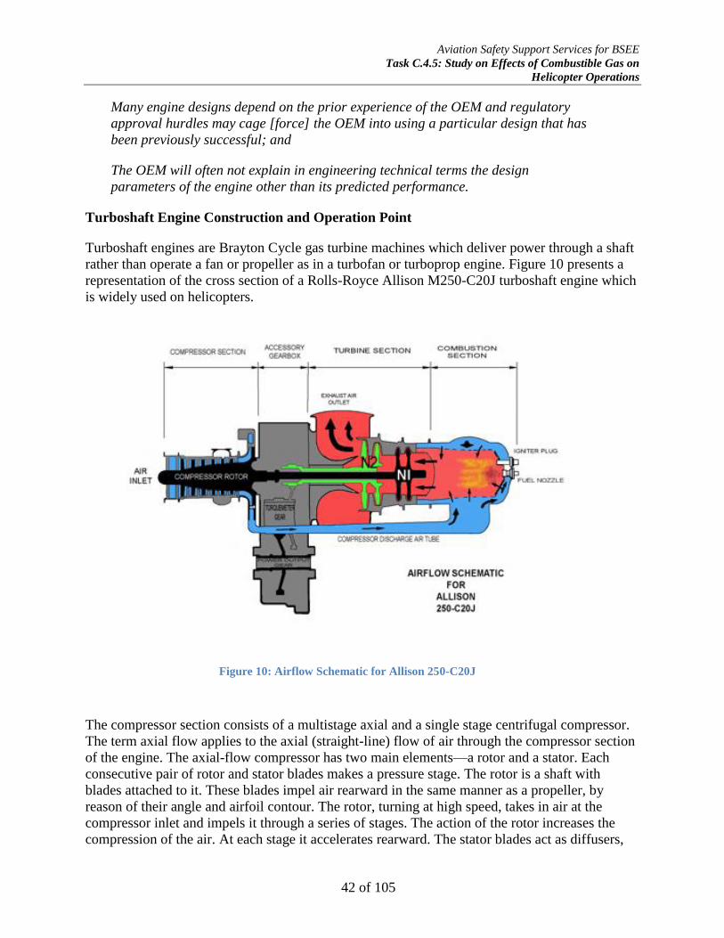
Aviation Safety Support Services for BSEE
Task C.4.5: Study on Effects of Combustible Gas on
Helicopter Operations
42 of 105
Many engine designs depend on the prior experience of the OEM and regulatory
approval hurdles may cage [force] the OEM into using a particular design that has
been previously successful; and
The OEM will often not explain in engineering technical terms the design
parameters of the engine other than its predicted performance.
Turboshaft Engine Construction and Operation Point
Turboshaft engines are Brayton Cycle gas turbine machines which deliver power through a shaft
rather than operate a fan or propeller as in a turbofan or turboprop engine. Figure 10 presents a
representation of the cross section of a Rolls-Royce Allison M250-C20J turboshaft engine which
is widely used on helicopters.
The compressor section consists of a multistage axial and a single stage centrifugal compressor.
The term axial flow applies to the axial (straight-line) flow of air through the compressor section
of the engine. The axial-flow compressor has two main elements—a rotor and a stator. Each
consecutive pair of rotor and stator blades makes a pressure stage. The rotor is a shaft with
blades attached to it. These blades impel air rearward in the same manner as a propeller, by
reason of their angle and airfoil contour. The rotor, turning at high speed, takes in air at the
compressor inlet and impels it through a series of stages. The action of the rotor increases the
compression of the air. At each stage it accelerates rearward. The stator blades act as diffusers,
Figure 10: Airflow Schematic for Allison 250-C20J

Aviation Safety Support Services for BSEE
Task C.4.5: Study on Effects of Combustible Gas on
Helicopter Operations
43 of 105
partially converting high velocity to pressure. Maintaining high efficiency requires small changes
in the rate of diffusion at each stage. Conversely, the centrifugal-flow compressor consists of an
impeller (rotor element), a diffuser (stator element), and a manifold. The impeller picks up and
accelerates air outward to the diffuser. The diffuser directs air into the manifold. The manifold
distributes air into the combustion section.
The combustion section provides the means for and houses the combustion process. Its function
is to raise the temperature of the air passing through the engine. This process releases energy
contained in the air and fuel by combustion. Igniters are installed in the combustion section to
initially ignite the fuel-air mixture. As long as the fuel and air are provided to the combustor at
the correct stoichiometric ratio and amount required for the power demand, the engine will
continue to run without the use of the ignitors.
The combination of the compressor section, its driving N1 turbine, and the combustion section is
often referred to as the gas generator. The gas generator’s function is to produce the required
energy to drive the power turbine (N2). The gas generator extracts about two-thirds of the
combustion energy, leaving approximately one-third to drive the power turbine, which in turn
drives the main and tail rotors through the power output shaft, as well as fuel control unit and
other accessories through the power-takeoff pads on the accessory gearbox.
The location of the combustion section is directly between the compressor and the turbine
sections. The combustion chambers are arranged coaxially with the compressor and turbines. The
chambers must be in a through-flow position to function efficiently. About one-fourth of the air
entering the combustion chamber area mixes with the fuel for combustion known as “primary
air.” The remaining air (secondary air) serves as temperature control which keeps the
temperature of the heated gases down to a level at which the liners, turbine nozzles, or blades
will not suffer thermal degradation and fail.
There is a real cycle or operation point for power output between the gas producer section and
the power turbine section (see Figure 11below) known as the match point. A match point is
simply a set of operating conditions (pressures, temperatures, and mass flows) were the
compressor and turbine can work in unison and equilibrium. The operation point is based on
compatibilities of flow, work, and rotational speed. This means:
The compressor work must match the work output of the turbine that drives it (N1); and
The mass flow rates must be compatible because gas turbines are continuous flow
machines. Any disturbance in the mass flow rate will cause a mismatch between the
compressor and turbine sections, decreasing or stopping the power output of the engine;
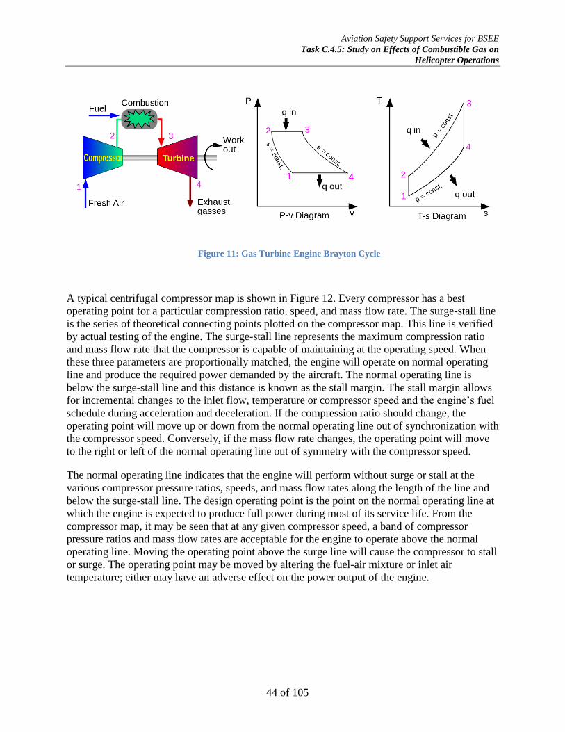
Aviation Safety Support Services for BSEE
Task C.4.5: Study on Effects of Combustible Gas on
Helicopter Operations
44 of 105
A typical centrifugal compressor map is shown in Figure 12. Every compressor has a best
operating point for a particular compression ratio, speed, and mass flow rate. The surge-stall line
is the series of theoretical connecting points plotted on the compressor map. This line is verified
by actual testing of the engine. The surge-stall line represents the maximum compression ratio
and mass flow rate that the compressor is capable of maintaining at the operating speed. When
these three parameters are proportionally matched, the engine will operate on normal operating
line and produce the required power demanded by the aircraft. The normal operating line is
below the surge-stall line and this distance is known as the stall margin. The stall margin allows
for incremental changes to the inlet flow, temperature or compressor speed and the engine’s fuel
schedule during acceleration and deceleration. If the compression ratio should change, the
operating point will move up or down from the normal operating line out of synchronization with
the compressor speed. Conversely, if the mass flow rate changes, the operating point will move
to the right or left of the normal operating line out of symmetry with the compressor speed.
The normal operating line indicates that the engine will perform without surge or stall at the
various compressor pressure ratios, speeds, and mass flow rates along the length of the line and
below the surge-stall line. The design operating point is the point on the normal operating line at
which the engine is expected to produce full power during most of its service life. From the
compressor map, it may be seen that at any given compressor speed, a band of compressor
pressure ratios and mass flow rates are acceptable for the engine to operate above the normal
operating line. Moving the operating point above the surge line will cause the compressor to stall
or surge. The operating point may be moved by altering the fuel-air mixture or inlet air
temperature; either may have an adverse effect on the power output of the engine.
Figure 11: Gas Turbine Engine Brayton Cycle

Aviation Safety Support Services for BSEE
Task C.4.5: Study on Effects of Combustible Gas on
Helicopter Operations
45 of 105
Compressor maps of actual engines are OEM proprietary trade secrets, judiciously guarded by
the manufacturer and not released to PwC/BSEE for this study.
Compressor Stall and Surge
The blades of an axial compressor or the vanes of a centrifugal compressor are airfoils in that
they have a critical angle of attack; exceeding the angle of attack will cause the compressor to
stall. The apparent angle of attack of the compressor is related to the inlet air velocity and
compressor speed. The two forces combine to form a vector, which is the actual angle of attack
of the air approaching the airfoil. A compressor stall is an imbalance between these two vector
quantities and cause air flowing through the compressor to slow down, stagnate (stop), or to
reverse direction (surge), depending upon the stall intensity. Stall conditions usually produce an
audible sound from a pulsating sound to a loud explosion or backfire, depending upon the
severity of the stall. Often, engine instrumentation does not indicate a mild stall condition known
as a transient stall. Severe stalls, known as “hung stalls,” or surge, significantly decay engine
performance with attendant un-commanded power rollback, internal damage, or complete engine
failure.26
Compressor stalls and surges may result from many causes, but most common are:
Turbulent or disrupted airflow to the engine inlet which reduces the velocity vector
(common to high speed aircraft only);
26 Otis, C.E. (1997). Aircraft Gas Turbine Powerplants. Englewood, CO: Jeppesen-Sanderson, Inc.
Figure 12: Example of Gas Turbine Engine Compressor Map

Aviation Safety Support Services for BSEE
Task C.4.5: Study on Effects of Combustible Gas on
Helicopter Operations
46 of 105
Excessive fuel flow caused by abrupt engine acceleration which reduces the velocity vector
by increasing combustor back pressure;
Excessively lean fuel mixture caused by abrupt engine deceleration which increases the
velocity vector by reducing combustor back pressure;
Contaminated or damaged compressors which increases the velocity vector by reducing
compression efficiency;
Damaged turbine components causing loss of power to the compressor and low
compression which increases the velocity vector by reducing compression efficiency; or
Engine operation above or below the design operating point which increases or decreases
the compressor speed vector.
When the engine is operating at its design operation point, the compressor blades are at a high
angle of attack which is often very close to the stall line but which gives the maximum efficient
pressure rise per stage of compression. There is also a maximum combustor back pressure and
restriction to flow created by the turbine system that can be tolerated by the engine. Thus, for the
engine to operate correctly and produce the power demanded by the aircraft for flight, the
compressor pressure ratio and mass flow rate must remain within a balanced relationship (the
operating point) as discussed above. This can only occur if the operating conditions (inlet
compression ratio, compressor efficiency, fuel flow, turbine efficiency, and exhaust nozzle flow)
all remain within the designed operating parameters. If they do not, a compressor stall or surge
may develop with partial or complete loss of engine power.
Flameout
A flameout occurs in the operation of a gas turbine engine in which the combustion in the engine
is unintentionally extinguished. If the upper flammability limit of the fuel-air stoichiometric ratio
is exceeded in the combustion chamber, the self-propagating flame will be extinguished by the
air flow through the engine. This condition is often referred to as a rich flameout and generally
results from very fast engine acceleration, in which an overly rich mixture causes the fuel
temperature to drop below the combustion temperature. It may also be caused by insufficient
airflow to support combustion.
A more common flameout occurrence is due to low fuel pressure and low engine speeds, which
typically are associated with high-altitude flight or reduced power settings. This situation usually
occurs with the engine throttled back during a descent, which can lead to the air-fuel
stoichiometric ratio being below the lower flammability limit (LFL), often referred to as the
lean-condition flameout. A stoichiometric mixture close to the LFL can easily cause the flame to
die out, even with a normal airflow through the engine.
Any interruption of the fuel supply can result in a flameout. This may be due to prolonged
unusual attitudes, a malfunctioning fuel control system, turbulence, icing, or fuel contamination,
starvation or exhaustion.
Aviation Safety Support Services for BSEE
Task C.4.5: Study on Effects of Combustible Gas on
Helicopter Operations
47 of 105
Gas Turbine Fuel Control
Fuel control for gas turbine engines may be by conventional hydro-mechanical fuel control
(HMFC), sometimes called a hydro-pneumatic fuel control system; electronic fuel control by use
of an electronic control unit (ECU); or through a full-authority digital engine control (FADEC).
While gas turbine engine fuel control is complex, a brief synopsis of each system is presented.
Hydromechanical Fuel Control (HMFC)
This fuel control system (Figure 13) is a hydro-mechanical metering device that consists of an
engine-drive fuel pump, a fuel control unit (FCU), a fuel metering section, power turbine
governor, and a fuel distribution manifold and injection nozzles. The HMFC is designed to
perform the following functions:
Change fuel flow with changes in air density as sensed at the engine inlet;
Schedule fuel flow during starting to prevent hot or hang starts;
Schedule fuel flow during engine acceleration to prevent compressor stall or surge and
excessive turbine gas temperature (TGT);
Schedule fuel flow for ground and flight idle conditions to prevent flameout;
Schedule fuel flow for flight based on compressor inlet air temperature and pressure,
compressor and power turbine speeds, and collective position;
Provide an overspeed governor for ground and flight operation;
Provide manual selection of main rotor speed through collective trimming system;
Allow for selection of power output (torque and TGT) in the flight range by movement of
the collective control coordinator to be automatically maintained regardless of altitude,
free-air temperature, or forward airspeed; and
Allow manual or electric cutoff of fuel for engine stop.
The fuel pump is typically a positive displacement gyrator-type pump driven from a PTO27
pad
on the accessory gearbox and delivers high pressure fuel to the FCU. The FCU is also driven
from a PTO pad on the accessory gearbox at a speed proportion to the compressor turbine speed
(N1). The FCU determines the fuel schedule of the engine to provide the required power output
and for controlling the speed of the compressor turbine. Engine power output is directly
dependent upon compressor turbine speed. Control of the compressor turbine is accomplished by
regulating the amount of fuel supplied to the combustion section of the engine through the
distribution manifold and injection nozzles.
27 PTO-power takeoff: a device that transfers mechanical power from an engine to another piece of equipment:
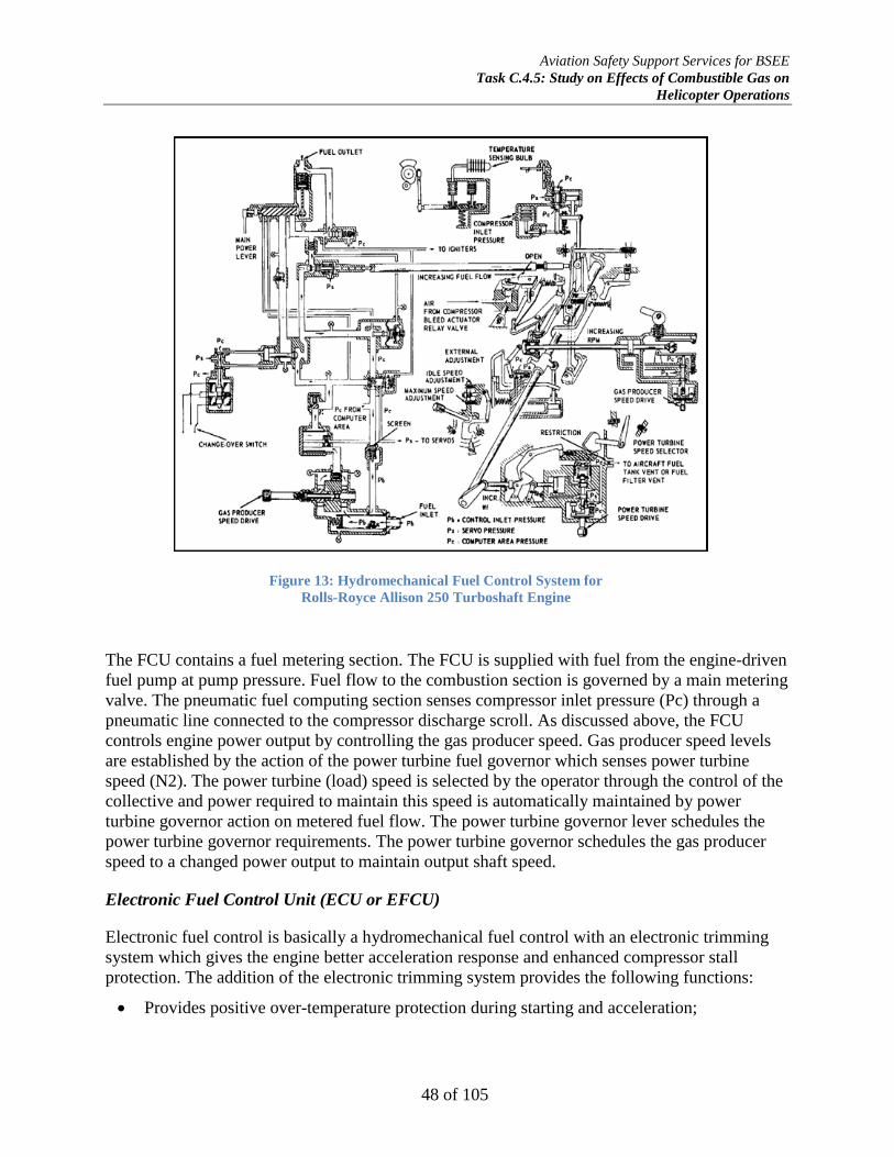
Aviation Safety Support Services for BSEE
Task C.4.5: Study on Effects of Combustible Gas on
Helicopter Operations
48 of 105
The FCU contains a fuel metering section. The FCU is supplied with fuel from the engine-driven
fuel pump at pump pressure. Fuel flow to the combustion section is governed by a main metering
valve. The pneumatic fuel computing section senses compressor inlet pressure (Pc) through a
pneumatic line connected to the compressor discharge scroll. As discussed above, the FCU
controls engine power output by controlling the gas producer speed. Gas producer speed levels
are established by the action of the power turbine fuel governor which senses power turbine
speed (N2). The power turbine (load) speed is selected by the operator through the control of the
collective and power required to maintain this speed is automatically maintained by power
turbine governor action on metered fuel flow. The power turbine governor lever schedules the
power turbine governor requirements. The power turbine governor schedules the gas producer
speed to a changed power output to maintain output shaft speed.
Electronic Fuel Control Unit (ECU or EFCU)
Electronic fuel control is basically a hydromechanical fuel control with an electronic trimming
system which gives the engine better acceleration response and enhanced compressor stall
protection. The addition of the electronic trimming system provides the following functions:
Provides positive over-temperature protection during starting and acceleration;
Figure 13: Hydromechanical Fuel Control System for
Rolls-Royce Allison 250 Turboshaft Engine

Aviation Safety Support Services for BSEE
Task C.4.5: Study on Effects of Combustible Gas on
Helicopter Operations
49 of 105
Allows the engine to operate closer to the maximum turbine gas temperature (TGT) due to
more accurate monitoring of fuel schedule;
Permits selection of any desired TGT to be automatically maintained without manually
trimming the engine;
Allows use of a wide variety of fuels with different lower heat values (LHV) such as
kerosene (JP4) without recalibration of the HMFC fuel control;
Permits the use of bleed air for anti-icing without changing power settings while avoiding
over-temperature conditions;
Trims fuel schedule to compensate for erroneous compressor inlet sensing by FCU caused
by different aircraft installations;
Provides more uniform collective settings for torque output; and
Provides a “lock in” function for fuel correction prior to landing for more balanced engine
power.
The system uses a number of electronic sensors for compressor speed (N1), power turbine speed
(N2), compressor pressure (Pc), collective control angle, and turbine gas temperature (TGT). The
sensors provide analog electric signals, typically 4-20 mA, to the electronic engine control
(EEC). The EEC then computes the fuel required fuel schedule based on the programed
operating parameters and power demand and actuates a proportional fuel control solenoid on the
hydromechanical fuel control unit to maintain the desired power output. In the event of a failure
of the EEC, the hydromechanical fuel control can act as a backup fuel control and the EEC can
be manually overridden by the operator.
Full-Authority Digital Engine Control (FADEC)
Many modern helicopters are equipped with a full-authority digital engine control (FADEC).
The FADEC consists of a digital computer, referred to as the electronic engine controller (EEC),
engine control unit (ECU), or the electronic engine control unit (EECU), and its related
accessories that control all aspects of aircraft engine performance. A true FADEC has no form of
manual override available, placing full authority over the operating parameters of the engine in
the decision algorithms of the EECU.
The EECU is a programmable logic controller (PLC) which has proportional-integral-derivative
(PID) control. The PID controller calculates an error value as the difference between measured
engine parameters and their desired operating points. The PID controller minimizes the error by
adjusting the engine power through use of a manipulated variable in fuel scheduling. For
optimum control of the engine, the PID is overlaid with a digital Kalman filter. The Kalman filter
uses a linear quadratic estimation algorithm that uses a series of engine parameter measurements
observed over time which contain statistical noise and other inaccuracies and produces estimates
of unknown variables that tend to be more precise than those based on the engine parameter
measurements alone. The PID-Kalman filter optimum FADEC provides robust control of engine
operation and protects against starting anomalies, compressor stall and surge, and over-torque,
over-temperature, or flameout conditions without pilot monitoring or intervention.
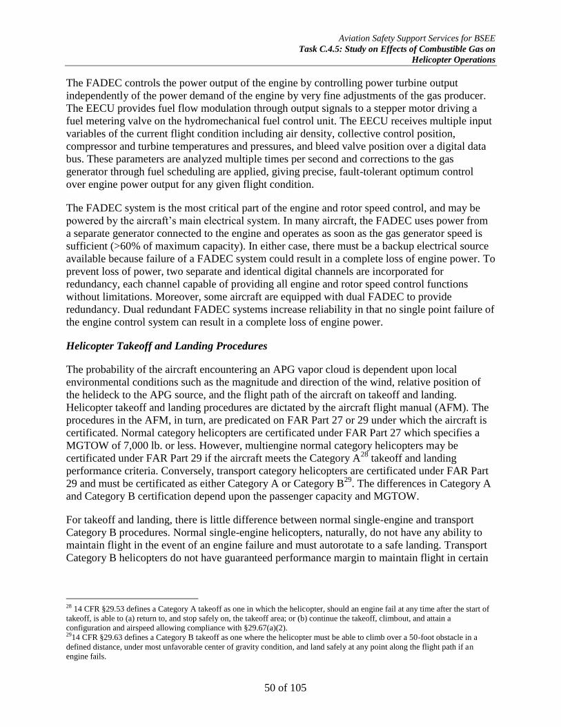
Aviation Safety Support Services for BSEE
Task C.4.5: Study on Effects of Combustible Gas on
Helicopter Operations
50 of 105
The FADEC controls the power output of the engine by controlling power turbine output
independently of the power demand of the engine by very fine adjustments of the gas producer.
The EECU provides fuel flow modulation through output signals to a stepper motor driving a
fuel metering valve on the hydromechanical fuel control unit. The EECU receives multiple input
variables of the current flight condition including air density, collective control position,
compressor and turbine temperatures and pressures, and bleed valve position over a digital data
bus. These parameters are analyzed multiple times per second and corrections to the gas
generator through fuel scheduling are applied, giving precise, fault-tolerant optimum control
over engine power output for any given flight condition.
The FADEC system is the most critical part of the engine and rotor speed control, and may be
powered by the aircraft’s main electrical system. In many aircraft, the FADEC uses power from
a separate generator connected to the engine and operates as soon as the gas generator speed is
sufficient (>60% of maximum capacity). In either case, there must be a backup electrical source
available because failure of a FADEC system could result in a complete loss of engine power. To
prevent loss of power, two separate and identical digital channels are incorporated for
redundancy, each channel capable of providing all engine and rotor speed control functions
without limitations. Moreover, some aircraft are equipped with dual FADEC to provide
redundancy. Dual redundant FADEC systems increase reliability in that no single point failure of
the engine control system can result in a complete loss of engine power.
Helicopter Takeoff and Landing Procedures
The probability of the aircraft encountering an APG vapor cloud is dependent upon local
environmental conditions such as the magnitude and direction of the wind, relative position of
the helideck to the APG source, and the flight path of the aircraft on takeoff and landing.
Helicopter takeoff and landing procedures are dictated by the aircraft flight manual (AFM). The
procedures in the AFM, in turn, are predicated on FAR Part 27 or 29 under which the aircraft is
certificated. Normal category helicopters are certificated under FAR Part 27 which specifies a
MGTOW of 7,000 lb. or less. However, multiengine normal category helicopters may be
certificated under FAR Part 29 if the aircraft meets the Category A28
takeoff and landing
performance criteria. Conversely, transport category helicopters are certificated under FAR Part
29 and must be certificated as either Category A or Category B29
. The differences in Category A
and Category B certification depend upon the passenger capacity and MGTOW.
For takeoff and landing, there is little difference between normal single-engine and transport
Category B procedures. Normal single-engine helicopters, naturally, do not have any ability to
maintain flight in the event of an engine failure and must autorotate to a safe landing. Transport
Category B helicopters do not have guaranteed performance margin to maintain flight in certain
28 14 CFR §29.53 defines a Category A takeoff as one in which the helicopter, should an engine fail at any time after the start of
takeoff, is able to (a) return to, and stop safely on, the takeoff area; or (b) continue the takeoff, climbout, and attain a
configuration and airspeed allowing compliance with §29.67(a)(2). 2914 CFR §29.63 defines a Category B takeoff as one where the helicopter must be able to climb over a 50-foot obstacle in a
defined distance, under most unfavorable center of gravity condition, and land safely at any point along the flight path if an
engine fails.

Aviation Safety Support Services for BSEE
Task C.4.5: Study on Effects of Combustible Gas on
Helicopter Operations
51 of 105
one-engine inoperative (OEI) flight regimes that Category A helicopters do. Figure 14 is a
diagram of a normal or Category B takeoff and emergency flight paths.
Figure 14: Normal and Category B Takeoff and Emergency Flight Paths
In a normal single-engine or Category B takeoff, the helicopter first performs an in ground effect
hovering (HIGE) power check then ascends to the takeoff decision point (TDP30
); sometimes, the
HIGE check and CDP may be the same altitude but is generally not less than one-half rotor
diameter or approximately 15 feet above the surface. The helicopter is then accelerated through
effective translational lift (ETL) and then to best rate of climb airspeed (or best angle of climb
airspeed for physical obstacles) to clear operational restrictions imposed by the height-velocity
(HV31
) diagram in the AFM32. In the event of an engine anomaly, the aircraft will either set back
down or will make an emergency return to the helideck; in the event there is insufficient engine
power for flight after departure, the aircraft will autorotate to a forced ditching.
FAR Part 29 Category A certificated helicopters, however, are multiengine aircraft designed with
engine and system isolation features that ensure that if one engine fails after takeoff or during
landing, the aircraft can safely land on the helideck or climb out from the point of failure and
attain a stabilized OEI33
flight path. When operating OEI, the inoperative engine must be able to
be isolated. Additionally, there are flight instrument requirements such as a radar altimeter to
allow the pilot to conduct a Category A takeoff. Figure 15 is a diagram of Category A takeoff
and OEI procedures.
30 TDP-Takeoff decision point (TDP): Category A: the first point from which a continued takeoff capability is assured under 14
CFR§29.59 and is the last point in the takeoff path from which a rejected takeoff is assured within the distance determined under
14 CFR§29.62. (see 14 CFR§29.55) 31 HV diagram-Height-velocity envelope -a helicopter specific graph showing the combination of height and forward velocity
(including hover) under which a safe landing cannot be made after failure of the critical engine. (see 14 CFR§29.87) 32 AFM-Aircraft Flight Manual 33 OEI-one engine inoperative
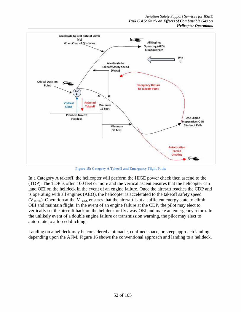
Aviation Safety Support Services for BSEE
Task C.4.5: Study on Effects of Combustible Gas on
Helicopter Operations
52 of 105
Figure 15: Category A Takeoff and Emergency Flight Paths
In a Category A takeoff, the helicopter will perform the HIGE power check then ascend to the
(TDP). The TDP is often 100 feet or more and the vertical ascent ensures that the helicopter can
land OEI on the helideck in the event of an engine failure. Once the aircraft reaches the CDP and
is operating with all engines (AEO), the helicopter is accelerated to the takeoff safety speed
(VTOSS). Operation at the VTOSS ensures that the aircraft is at a sufficient energy state to climb
OEI and maintain flight. In the event of an engine failure at the CDP, the pilot may elect to
vertically set the aircraft back on the helideck or fly away OEI and make an emergency return. In
the unlikely event of a double engine failure or transmission warning, the pilot may elect to
autorotate to a forced ditching.
Landing on a helideck may be considered a pinnacle, confined space, or steep approach landing,
depending upon the AFM. Figure 16 shows the conventional approach and landing to a helideck.

Aviation Safety Support Services for BSEE
Task C.4.5: Study on Effects of Combustible Gas on
Helicopter Operations
53 of 105
Figure 16: Conventional Approach and Landing Flight Path
The helicopter will normally conduct both a high and low reconnaissance of the helideck to
ascertain hazards. Once the pilot is sure that it is safe to land, an approach into the wind is made
to the landing decision point (LDP). If engine operations are normal or an engine fails after
reaching the LDP, the pilot will normally elect to continue the landing to the helideck as the
safest course of action. However, if the engine operations are abnormal or an engine fails before
the LDP, the pilot may elect to fly off OEI and return to a shore heliport or runway.
Understanding of Category A and B takeoff, landing, and emergency procedures discussed above
is necessary to understand the hazards presented by APG during these operations. Since methane
is lighter than air and most stacks and many flare booms are above the helideck, it is unlikely
that methane would accumulate on the helideck and present a hazard to the aircraft while on the
deck. However, Category A takeoff procedures or Category B climb out may present a methane
ingestion hazard to the aircraft if the wind is within the critical sectors discussed earlier and
depicted in Figure 4.

Aviation Safety Support Services for BSEE
Task C.4.5: Study on Effects of Combustible Gas on
Helicopter Operations
54 of 105
Effects of Methane Ingestion on Turboshaft Power Output
Methodology
This task requires a technical analysis to determine the concentration for each flammable gas
which may have an effect on helicopter performance, and to evaluate the effect of hydrocarbon
gas ingestion of each combustible gas on each helicopter (make, model, and engine) at the
anticipated concentration. As discussed above, more than 90 percent of APG gas released from
offshore installations is methane so only methane need be considered to produce a valid result.
Concerning the make, model, and engine of helicopters used on the OCS, there is no current test
data available in order to conduct an analysis for each make, model, and engine configuration.
However, according to the Helicopter Safety Advisory Conference (HSAC) data, single-engine
turbine helicopters make up the bulk of the OCS helicopter fleet. These helicopters are powered
by more than 30 different engine model numbers. All of these engine models, however, share
common gas producer characteristics and fall into one of three categories:
Joined multistage-axial and single-stage centrifugal compressor;
Single-stage centrifugal compressor; or
Split multistage-axial and single-stage centrifugal compressor.
Thus, an effective analysis was completed by analyzing the effects of methane ingestion on the
three types of compressor configurations. Therefore, three representative turboshaft engines
widely used in helicopter power applications are selected to perform this engineering analysis:
Engine A has a joined multistage axial and single-stage centrifugal compressor section, a
two-stage low-pressure gas generator turbine (N1), and two-stage high-pressure power
turbine (N2) section;
Engine B has a single-stage centrifugal compressor section, a two-stage low-pressure gas
generator turbine (N1), and two-stage high-pressure power turbine (N2) section; and
Engine C has a split single-stage axial and single-stage centrifugal compressor section, a
single-stage gas generator turbine (N1), and a single-stage power turbine (N2) section.
These engines are chosen to represent a statistically valid sample of the helicopter turboshaft
engine population operating on the OCS.
Figure 17 presents a cause and effect diagram of possible events due to APG ingestion in a
turboshaft engine. The dependent variables are ingestion of APG, compressor surge, and actual
crash of the aircraft; conversely, the independent variables are the APG stoichiometric
concentration in air, and the compressor configuration of the representative engine. For example,
a helicopter may or may not encounter an invisible APG vapor cloud, depending upon wind
direction. If the helicopter encounters an APG vapor cloud, the stoichiometric concentration may
cause a compressor surge. The effect of the compressor surge, perforce, depends on its severity
and the time that the fuel control or the pilot has to respond to the event to prevent a mishap.

Aviation Safety Support Services for BSEE
Task C.4.5: Study on Effects of Combustible Gas on
Helicopter Operations
55 of 105
Due to the thermodynamic operating characteristics of gas turbine turboshaft engines, methane
gas ingested into the engine could either be ignited through adiabatic compression heating above
the autoignition temperature causing a compressor surge, or enrich the fuel causing an over-
temperature condition with associated internal engine pressure increase, increase in compressor
backpressure, or over-speed condition, all of which may cause a partial or total loss of engine
power.
The engineering modeling of methane ingestion effects on turboshaft engine operating point and
real cycle power output was performed by the gas turbine engine laboratory (PropLab) at the
Aerospace Engineering Department of Texas A&M University in College Station, Texas. The
preliminary engineering analysis report is provided as Appendix F as a separate document.
The engine response to methane ingestion was mathematically modelled using the required
engine parameters to describe the real cycle power output at maximum takeoff power. These
include the overall pressure ratio (OPR), mass airflow rate (�̇�𝑎𝑖𝑟) and power (hp). Additional
parameters, including inlet diffuser efficiency, compressor efficiency, turbine inlet temperature
Figure 17: APG Ingestion Event Tree

Aviation Safety Support Services for BSEE
Task C.4.5: Study on Effects of Combustible Gas on
Helicopter Operations
56 of 105
(T3), pressure drop in combustor section (Δp), combustor efficiency, mechanical losses, turbine
efficiency, power turbine efficiency, differential pressure at nozzle expansion, and nozzle
efficiency, are assumed to obtain a brake specific fuel consumption (BSFC) in μg/J at takeoff
conditions when the pressure is one bar and the static temperature is 288.16°K. Engine operating
parameters were derived from published engine operation and maintenance manuals,
performance charts, and proprietary data provided by the engine OEM. Standard Jet A fuel is
assumed in the real cycle computation such that the lower heating value (LHV) is 43,500 kJ-kg-1
(with the exception of Engine C which was 43,136 kJ-kg-1
) and the stoichiometric ratio between
mass flow rates and air and fuel was 14.66.
The real cycle for the three turboshaft engines was calculated using a numerical summation for
enthalpy (kJ-kg-1
), temperature (°K), entropy (kJ-(kg-°K)-1
), and pressure (bar). These values are
used to describe the theoretical effect of methane ingestion on the compressor (adiabatic
compression ignition) and fuel enrichment on the combustor on the real cycle and thus power
output of each representative engine. Fractions of methane ingestion are 0, 5, 10, and 15 percent
by volume with all concentrations reported by mass.
The effect on the combustor and power output as a function of the turbine inlet temperature
(TIT) as an expression of engine power output and was calculated from the energy conservation
equation. The conservation of energy between the compressor and combustor is calculated as
follows:
�̇�𝑎1ℎ𝑎(𝑇2∗) + �̇�𝐶𝐻4(ℎ𝐶𝐻4(𝑇2
∗) + 𝜉𝐶𝐻4𝐿𝐻𝑉𝐶ℎ4) + �̇�𝑓(ℎ𝑓 + 𝜉𝑐𝑜𝑚𝑏𝐿𝐻𝑉)
= �̇�𝑎𝑙𝑒𝑓𝑡ℎ𝑎(𝑇3
∗) + �̇�𝜆=1ℎ𝜆=1 + �̇�𝑝𝑟𝑜𝐶𝐻4ℎ𝑝𝑟𝑜𝐶𝐻4(𝑇3∗)
where:
�̇�𝑎1 is the mass flow rate of air after methane injection;
ℎ𝑎 is the enthalpy of air;
�̇�𝐶𝐻4 is the mass flow rate of methane;
𝜉𝐶𝐻4 is the efficiency of methane combustion;
𝐿𝐻𝑉𝐶ℎ4 is the lower heating value (LHV) of methane;
�̇�𝑓 is the mass flow rate of fuel (Jet A) prior to methane ingestion;
ℎ𝑓 is the enthalpy of fuel;
𝜉𝑐𝑜𝑚𝑏 is the efficiency of Jet A combustion;
LHV is the lower heating value of Jet A fuel;
�̇�𝑎𝑙𝑒𝑓𝑡 is the mass flow rate of air that did not burn in the combustor;
�̇�𝜆=1 is the mass flow rate of combustion products resulting from the stoichiometric
combustion of Jet A fuel;

Aviation Safety Support Services for BSEE
Task C.4.5: Study on Effects of Combustible Gas on
Helicopter Operations
57 of 105
ℎ𝜆=1 is the enthalpy of combustion products resulting from the stoichiometric combustion
of Jet A fuel;
�̇�𝑝𝑟𝑜𝐶𝐻4 is the mass flow rate of combustion products resulting from the stoichiometric
combustion of methane;
ℎ𝑝𝑟𝑜𝐶𝐻4 is the enthalpy of combustion products resulted from the stoichiometric
combustion of methane; and
𝑇3∗ is the turbine inlet temperature (TIT) in °K at stagnation.
Response to the changes in the turboshaft engine real cycle by various fuel control systems is
qualitatively described.
Assumptions and Limitations
The methane ingestion in the compressor section is assumed to be uniform. Non-uniformity
conditions are ignored but may cause local stall cells to form which are not predicted by this
modelling.
Methane ingestion at the engine intake is assumed to be at the specified concentrations. The
actual probability of these methane concentrations is dependent upon non-linear factors such as
release rate, distance to source, wind magnitude and direction, and mechanical mixing of clean
air into vapor cloud by the main rotor and are ignored.
Effects of local fluid strain rate and effect on auto-ignition and flame propagation is also ignored.
If fluid strain rate is considered, this would lower the probability of an autoignition.
Any ram pressure recovery at the compressor is ignored as this effect does not occur until 100
m/s forward airspeed (194 KTAS34
).
Results
Effect on Compressor Section
Data calculated by the mathematical modelling show that methane ingestion slightly reduces
temperature at the exit of the compressor. In all representative turboshaft engines, the
temperature at the exit of the compressor is below the minimum autoignition temperature of
810°K35
. Therefore, it is unlikely within a reasonable degree of engineering and scientific
certainty that the methane will ignite in the compressor due to adiabatic heating.
34 KTAS-knots true airspeed; velocity in nautical miles per hour corrected for temperature and pressure altitude 35 Robinson, C. and Smith, D.B. (1986). The auto-ignition temperature of methane. Journal of Hazardous Materials 8, 199-203.
Aviation Safety Support Services for BSEE
Task C.4.5: Study on Effects of Combustible Gas on
Helicopter Operations
58 of 105
Effect on Combustor Section
This section presents the effect of methane ignition in the combustor on the turbine inlet
temperature (T3, TIT). The TIT was calculated from the energy conservation equation discussed
in the methodology. It was assumed that the mass flow rate of fuel (Jet A) did not change
immediately after methane ingestion, that is, the fuel control unit scheduler did not have
sufficient time to adjust to the lower amount of combustion air. Therefore, the temperature
reached immediately after methane ingestion is the top limit for the engine, since subsequently
the fuel scheduler should reduce the mass flow rate of fuel (Jet A) once the methane ignites in
the combustor.
The TIT variation as a function of the mass flow rate of methane ingested was assumed that 90%
of the lower heating value of methane, which is 50,050 kJ-kg-1
, was transferred to the working
fluid. It was also assumed that the lower heating value of Jet A is 43,136 kJ-kg-1
, which is
identical to the value used for Engine C, but different from the value previously used for Engines
A and B (see Figure 1 in Appendix F).
The methane volume fraction range (1% to 18%) corresponds to a mass fraction range of 0.55%
to 10.83%.
Discussion
The results provided in Appendix F revealed that, for the three representative engines examined,
the temperature in the compressor is not high enough to ignite the methane-air mixture. Even if
the temperature would exceed the minimum auto-ignition temperature, the flow strain would
require an even higher temperature for auto-ignition.
The methane will certainly ignite in the combustor. Consequently, the turbine inlet temperature
(TIT) will sharply increase. For a methane volume fraction ranging between 1% and 18%, the
temperature will increase be approximately 120K36
to 1,100 K. Depending on the temperature
rise, the pressure of in the combustor section will rise with two effects. First, the back pressure
on the compressor will rapidly increase, upsetting the operating point and moving it beyond the
surge line on the compressor map, more likely than not resulting in a compressor stall and surge.
Second, the increase in combustor pressure will increase the N1 and N2 turbine speeds not
commanded by the fuel control system. The fuel control system will sense this as an overspeed
condition and decrease the fuel schedule, even to the flight idle underspeed governor limit,
causing an un-commanded power rollback as the methane fuel enrichment is rapidly exhausted.
Recovery of the engine output power depends on the type of fuel control unit (HMFC, ECU, or
FADEC) and the control inputs of the operator. Because the effects of the methane ingestion are
rapid, there may likely be insufficient reaction time for the pilot to diagnose the condition and
would have no option but to suffer the effects of an engine power loss.
Even small amounts (mass fractions) of methane, as low as 0.4% by volume, may cause a
power loss in the representative engines.
36 K (Kelvin)- the primary unit of temperature measurement in fluid dynamics; one of the seven base units in the International
System of Units (SI); e.g. absolute zero (0 K) is equivalent to −273.15 °C (−459.67 °F)

Aviation Safety Support Services for BSEE
Task C.4.5: Study on Effects of Combustible Gas on
Helicopter Operations
59 of 105
Hydromechanical fuel control units (HMFC), while robust and not as complex as electronic
control units, are probably not as resistant to transient conditions such as a compressor stall or
TIT spikes caused by a methane ingestion event. Electronic fuel trimming systems, while more
efficient than HMFC, are likely no more resistant to the type of transient conditions caused by
methane ingestion. FADEC systems that incorporate a signal to noise control filtering system
such as a Kalman filter, however, are more likely than not to be resistant to engine power
perturbations caused by small methane ingestion events (<0.4%).
Note: The actual performance of the fuel control units cannot be modeled or determined
without empirical testing on a turboshaft engine so equipped.
Subtask C.4.5.3 – monitoring and warning systems 2.8
General Description
This subtask requires the identification and evaluation of (1) technologies to monitor
combustible gases that could adversely affect helicopter operations in the vicinity of an OCS
facility (on the helideck and during approach and departure); (2) the determination if/how a
sensor for vented gas can be devised/installed around the helidecks and oil rigs to advise pilots of
the quality of the environment they intend to fly through on takeoff and landing; and (3), to
investigate mitigation strategies such as installing diffusers or other systems on vent stacks that
would reduce the risk of methane or combustible gases.
Monitoring Technologies
Methodology
A detailed review of available hydrocarbon gas detection systems and detector specifications was
made, including industry best practices.
Results
There are several, mature hydrocarbon gas detection technologies used in offshore,
petrochemical, and other hydrocarbon hazard facilities; these are catalytic gas detection, infrared
gas detection, and hydrocarbon gas imaging.
Catalytic Gas Detection
A catalytic gas detector works by the electrical heating of a wire and a rare earth catalyst as the
sensing element. The element responds to an influx of combustible hydrocarbon gas by
increasing its temperature and resistance of the sensing element. This change in resistance is
proportional to the volume fraction of the hydrocarbon gas in air. The change in resistance is
converted to an analog voltage signal which can then be displayed on an indicator or used to
activate an alarm system.
Poisoning of this type of detector can be caused by substances such as silicon-based greases, and,
in some cases, excessively high background gas concentrations outside the upper explosive limit.

Aviation Safety Support Services for BSEE
Task C.4.5: Study on Effects of Combustible Gas on
Helicopter Operations
60 of 105
Other problems associated with catalytic detectors include the blockage of the sintered disc with
particles such as oils, fine dust, salt, grit, corrosion or even water.
Catalytic detectors are point-source type detectors and must be located in very close proximity to
potential points of gas release to be effective. Moreover, the calibration of the detector must
account for differences in gas densities, and therefore, must be mounted at an elevated level to
ensure detection of a methane gas release. As such, the catalytic detectors are not considered best
practice for methane detection and are not used in facilities with the potential for large methane
releases such as LNG plants or vessels.
Infrared Gas Detectors
Advances in infrared (IR) technology have produced both point and open-path detector systems.
IR gas detectors operate by the physical principle that APG absorbs infrared energy at certain
wavelengths.
The point IR gas detector is a sealed detection tube containing both IR transmitter and receiver.
The output is proportional to the amount of IR absorbed by the gas and thus the gas present in
the vicinity of the detector.
Conversely, the open-path IR gas detector is synonymous with a conventional optical beam
smoke detector in appearance and configuration. It works by measuring the attenuation of IR by
a vapor cloud between the transmitter and receiver over a large area (line of sight). The optical
beam measures the total amount of gas present in the sensor path as if a row of point-type
detectors had been placed end to end in a line; this allows the significance of the gas release
hazard to be estimated.
Open-path detectors are effective over a long distance with typical coverages up to 300 meters
(985 feet). Practical effective detection limits are less than 100 meters (328 feet) to ensure
accuracy and reduce nuisance alarms. This operational feature makes these types of detector
ideal for perimeter monitoring. However, like all optically-based detector systems, they are very
susceptible to contamination, rain or fog.
Hydrocarbon Gas Imaging
One technology which may be viable for warning pilots of potential APG hazards it a
hydrocarbon gas imaging system. These systems are quite new and similar to forward-looking
infrared (FLIR) technology. Using this imaging technology, it is possible to actually ‘see’ a
vapor gas cloud in real time. It is also possible to compare the gas cloud to the condensate cloud
surrounding the gas cloud. In a test at Texas A&M University on an extremely humid day, the
condensate cloud was three to four times the size of the methane cloud, but also acted as an
insulator in stagnant wind conditions which would have rendered IR detectors useless.37
37 Most APG could be visually detected at ground level or at one or two meters height. Gas imaging may be carried out up to 50
meters (164 feet) from the target area. This technology may be explored to see if it could be adapted to helideck monitoring.

Aviation Safety Support Services for BSEE
Task C.4.5: Study on Effects of Combustible Gas on
Helicopter Operations
61 of 105
Warning Systems
A helicopter pilot needs real-time information concerning the wind direction and speed,
temperature, and air quality in the immediate area of the helideck, in order to make a well-
informed decision on whether to initiate an approach to landing or to takeoff. The questions that
must be asked are:
What is the quality of the air in the immediate vicinity of the landing surface?
What is the quality of the air on the approach path?
What is the quality of the air on the departure path?
To capture sufficient quality and quantity of information concerning the properties of the air in
the vicinity of the helideck, multiple sensors would need to be installed. A sensor designed to
report the air quality of the helideck and approach and departure paths would need to be located
in a position to allow real-time sampling of those critical areas. The mounting structure and
sensor would need to be positioned so that they did not create in flight hazards that were
disproportionate to their intended utility.
On first approximation, it appears that open-path IR type gas detectors would be ideal for
monitoring helidecks for APG contamination. However, there are severe limitation that renders
the system non-effective for warning the helicopter pilot of an APG hazard.
It would be possible to mount both point and open-path gas detectors in the plume path from the
flare to the helideck and on the helideck itself, but the flight path above the helideck could not be
covered. Therefore, depending upon wind magnitude and direction, as well as the volume of the
APG release, all approach and departure paths for the aircraft could not be effectively monitored.
This is especially true for Category A takeoff for twin-engine transport helicopters which require
a vertical ascent as discussed above.
Locating point detectors on the aircraft itself would not be feasible as the detector would not
activate until the aircraft had entered the vapor cloud, thus not providing the pilot with enough
reaction time to avoid the hazard.
Typically, the alarm setpoint is 20% of LFL to ensure adequate detection as they are less reliable
at lower setpoints, and to reduce nuisance alarms. As discussed above, 10% LFL is the maximum
recommended exposure for turboshaft engines. Thus, setting the detector at 10% LFL may
degrade the detection capability of the system at the recommended maximum gas exposure level
and generate nuisance alarms, degrading personnel confidence in the efficacy of the system.
Mitigation Strategies
Methodology
A detailed review of design of flare systems was made, including industry best practices.
Consultation with process safety and design subject matter experts was also conducted.
Aviation Safety Support Services for BSEE
Task C.4.5: Study on Effects of Combustible Gas on
Helicopter Operations
62 of 105
Results
As discussed above, APG is normally separated from liquid hydrocarbons. If economically
viable, the gas is separated into its constituent components, compressed and piped to shore for
additional processing, distribution and sale. If the amount of APG is not sufficient to be
economically viable for separation and sale, it is hot flared or cold vented to the atmosphere.
Numerous gas flow meters exist and are currently in use to determine the amount of APG
released into the atmosphere and routinely used on offshore facilities to satisfy EPA greenhouse
gas reporting requirements.
There is no technological means of eliminating APG from base hydrocarbon production. It is
technologically possible to entrain air into the flare outlet such that the percentage of APG is
below the 10% LFL at discharge, using pressure and flow regulating valves in the flare header,
coupled with venturi mixers at the flare stack. However, this system would have to be designed
and retrofitted to all legacy facilities at substantial cost. Moreover, the system would have to be
designed such that the volumetric concentration could be varied between the desired 10% of LFL
to within the flammability limits such that the gas could be hot flared when desired or required.
There are some flows which the intermittent volume of APG would render this system
impracticable due to complexity. Lastly, increasing complexity into the flare system may
produce other hazards such as leak points or additional on-facility hydrocarbon inventory which
may result in a greater fire and explosion hazard than the facility was originally designed to
withstand.
In lieu of flaring or venting APG, the constituent gases may be separated and concentrated on
board the facility until sufficient quantities exist for economically offloading, processing,
distribution, and sale.
For example, two ways of storing methane gas are by compression to generate compressed
natural gas (CNG) or cryogenic liquefaction to produce liquefied natural gas (LNG); other
constituents of APG such as butane and propane could be separated and compressed to generate
liquefied petroleum gas (LPG). Once the inventory of CNG, LNG or LPG reaches an
economically viable level, it can be offloaded from the facility to a transfer vessel and taken to
shore for processing, distribution and sale. This may only be economically effective for large
producing wells.
However, for legacy facilities, more likely than not, there is insufficient space to install the
required compressors, storage vessels, and associated piping to make it economically feasible.
Moreover, concentration of APG constituents presents fire, explosion, and blast effects hazards
for which the facility was not originally designed. This is one of the root causes of the Piper
Alpha disaster – failure to consider the increased hydrocarbon inventory when converting from
gas to both gas and liquid hydrocarbon processing. For example, the blast walls on the
processing facility or the separation distance between the processing and accommodation
platforms may be insufficient if the APG processing capability is added.
Aviation Safety Support Services for BSEE
Task C.4.5: Study on Effects of Combustible Gas on
Helicopter Operations
63 of 105
Recommendations 3.
This section provides recommendations to minimize or eliminate the release of methane or other
combustible gases within an area determined to pose a risk to helicopter operations to BSEE
upon completion of all activities under Task 5 as required by Subtask C.4.5.4, Recommendation
Report.
Subtask C.4.5.1 – review and assess helideck construction standards 3.1
Review of domestic and international regulations and standards reveals that the
recommendations provided in API 14J and the draft version of API 2L-1 are sufficiently
comprehensive to ensure that hazards presented by APG are considered and mitigated.
Engineering studies should be commissioned to predict the theoretical concentration of APG that
may be present in an APG vapor cloud based on computational fluid dynamics (CFD) gas
dispersion modelling. These studies should consider the effect the mechanical mixing of clean air
from the main rotor during approach or departure.
These studies should define several representative platform configurations prevalent in US OCS
operations; and examine multiple natural wind scenarios, including “light and variable”, “steady-
state” and “gusty” conditions. The effects of approaching and departing helicopters of various
weight categories should also be incorporated into the modelling. This study may identify
platform configurations that are problematic for helicopter operations with respect to hot exhaust
plumes and APG venting.
Increased temperatures due to hot exhaust plumes are as great or greater risk than APG ingestion
due to significant increased risk of gas turbine compressor stall. The CFD analyses
recommended above should include temperature distributions and the position of the 2°C
isotherm should be verified as specified in NORSOK C004.
BSEE should work with HSAC to improve the HSAC RP No. 92-4 to develop enhanced
operational and communication procedures to mitigate the hazards presented by APG as
discussed below.
Subtask C.4.5.2 (a) – identify and list each regulation that addresses venting and 3.2
flaring of methane on OCS facilities under BSEE jurisdiction, highlighting any
regulation that favors one method over the other.
APG flaring and venting on the OCS, with the exception of EPA reporting requirements, is
essentially unregulated. Under 42 U.S.C. 7401, et seq. or 30 C.F.R. §250.1900, et seq., it does
not appear that BSEE has any authority to regulate APG venting or flaring under SEMS or the
Clean Air Act.
Subtask C.4.5.2 (d) – (1) determine the concentration parameters for each 3.3
flammable gas to determine the effect on helicopter operations; and (2)
specifically identify if each helicopter engine manufacturer has a known

Aviation Safety Support Services for BSEE
Task C.4.5: Study on Effects of Combustible Gas on
Helicopter Operations
64 of 105
percentage of methane (or other combustible gas) to volume that is hazardous to
engine operations.
No publicly available research on the hazard of APG ingestion has been conducted by the
turboshaft engine OEMs, or by regulatory agencies in the U.S. In the investigation of APG
ingestion mishaps, the NTSB has relied on USAF AFWAL-TR-80-2090, Water Ingestion into
Axial Flow Compressors, Part III, Experimental Results and Discussion, which tangentially
mentions methane ingestion effects when the gas was used to simulate rainwater ingestion. This
report was issued in 1981 and considerable changes in technology with respect to empirical
engine testing and instrumentation has occurred in the last three decades. The FAA Rotorcraft
Directorate (ASW-100) and the FAA Rotorcraft Certification Office (ASW-170), both located at
Meacham Field in Fort Worth, Texas, should be invited to participate in an engineering empirical
test on the APG ingestion hazard. Since the independent variable is the fuel control unit, this
study should include empirical testing on one representative engine equipped with a
hydromechanical fuel control and one with a FADEC system to verify the mathematical
modelling and resistance to engine performance anomalies. The OEM should also be encouraged
to participate and provide technical assistance.
Subtask C.4.5.2 (e) – evaluate the effect of the ingestion of each combustible gas 3.4
on each helicopter (make, model, and engine), at anticipated concentration
levels.
Mathematically modelling the effects of methane ingestion on turboshaft engines suggests that
less than one-half of one percent by volume of methane may have an adverse effect on engine
power resulting in a mishap. From the NTSB data reviewed, it appears that an APG ingestion
mishap may have occurred every 1.5 years on the OCS; near miss data for when an APG
ingestion event occurred but did not result in the loss of the aircraft is not reported or collected.
Therefore, rotorcraft operators should be encouraged to submit incidents through its SafeOCS or
a similar incident reporting system. These incidents should be thoroughly investigated through a
root cause analysis (RCA) methodology and the data trended over time to quantify the magnitude
of the hazard.
Until the effect of APG ingestion is verified by empirical experiment, universal precautionary
operational procedures to mitigate the APG hazard should be promulgated. This could be
accomplished either by regulatory changes or through industry best practices such as
modification of HSAC RP 92-4.
Until a CFD gas dispersion model is constructed for each offshore oil & gas facility in
accordance with the recommendation in Subtask C.4.5.1 above, helidecks should universally be
considered contaminated with APG whenever the wind direction is within 10 degrees of the
platform’s designated flaring/venting critical wind zone and the facility is cold venting APG.
Critical approach and departure wind zones, as depicted in Figure 18, below should be
established for each facility. If the facility does not have a Helicopter Traffic Coordination
Center (HTCC), a meteorological monitoring or helideck monitoring system (HMS), in
accordance with NORSOK C004, should be installed in the communication center for the
facility. Positive radio contact with the facility must be made prior to landing or departure.

Aviation Safety Support Services for BSEE
Task C.4.5: Study on Effects of Combustible Gas on
Helicopter Operations
65 of 105
The facility must communicate meteorological and safety advisory information to the incoming
aircraft in addition to declaring the helideck clear to land or depart. This information should
include wind speed and direction, temperature, dew point, barometric pressure, and cautionary
advisories for APG cold venting, a general caution to remain clear of the flare boom or stack and
hot exhaust systems, and an advisory on any known helicopter traffic similar to a UNICOM
request for aerodrome information.
The no fly zone azimuths should be provided on a facility diagram to aid in the safety
communications.
Facility offshore installation managers (OIM) and personnel who communicate with incoming
and departing aircraft should be trained on the procedures. These procedures are especially
applicable to Category A takeoffs where the vertical ascent requirements for OEI safety may
increase the probability of encountering an APG vapor cloud. Helicopters approaching or taking
off from a facility without a positive communications exchange are operating at increased risk.
Gas flow monitoring devices should be installed in the APG distribution system to report the
instantaneous volume of APG venting if the helideck is to be operational during APG release. As
recommended in Subtask C.4.5.3 (a) above and based on a CFD gas dispersion study, point and
open-path gas detectors should be installed on the helideck perimeter and in the path from the
APG source to the helideck. Installation of a helideck visual warning indication system as
discussed in API RP 2L-1, 5th Edition, should be considered.
It should be noted that hot flaring of APG does not provide a greater level of protection to the
aircraft. While it does eliminate the APG and make the flare plume more visible to the pilot, as
discussed in NORSOK C004, hot gas emissions are a serious risk to turboshaft engines, perhaps
even more significant than methane ingestion. Momentary temperature increases of 2°C or more
may result in an engine power loss event. Unless the position of the 2°C isotherm line, with
respect to the helideck position at the least favorable wind conditions, is verified by CFD
analysis, hot flaring of the APG may not provide any more protection than venting APG;
therefore, continuous hot flaring is not recommended as a safety measure.
Lastly, while FADEC controlled engines may have more resistance to transient conditions, at
least one mishap directly attributable to APG ingestion occurred to an aircraft equipped with a
FADEC. Therefore, universal precautions concerning the APG hazard are recommended when
operating in the immediate vicinity of a facility that may be venting APG and a restriction to
FADEC equipped aircraft only is not recommended without empirical engine testing.
Subtask C.4.5.3 (a) – monitoring technologies 3.5
Installation of a combination of point and open-path IR gas detectors in and around the helideck
may be feasible if the setpoint of the detector could be calibrated to 10% LFL of methane or
lower without degrading the detection capability of the system or generation of nuisance alarms.
An engineering study to determine the efficacy of this technology should be commissioned.
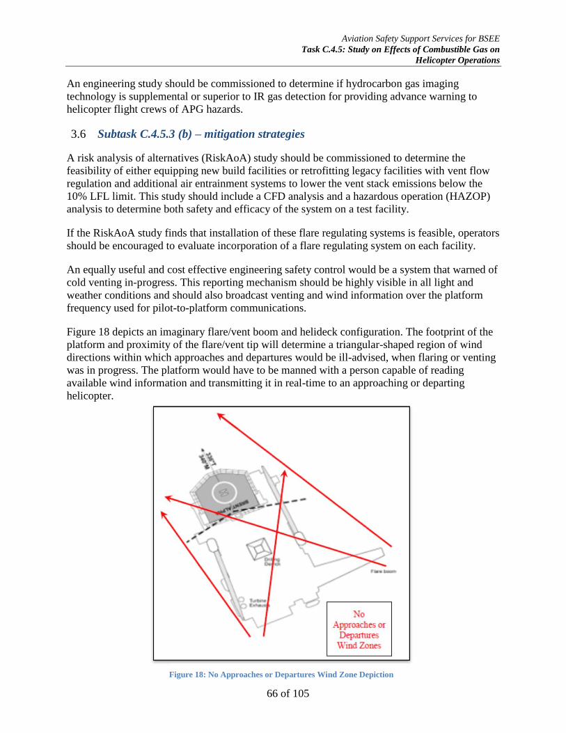
Aviation Safety Support Services for BSEE
Task C.4.5: Study on Effects of Combustible Gas on
Helicopter Operations
66 of 105
An engineering study should be commissioned to determine if hydrocarbon gas imaging
technology is supplemental or superior to IR gas detection for providing advance warning to
helicopter flight crews of APG hazards.
Subtask C.4.5.3 (b) – mitigation strategies 3.6
A risk analysis of alternatives (RiskAoA) study should be commissioned to determine the
feasibility of either equipping new build facilities or retrofitting legacy facilities with vent flow
regulation and additional air entrainment systems to lower the vent stack emissions below the
10% LFL limit. This study should include a CFD analysis and a hazardous operation (HAZOP)
analysis to determine both safety and efficacy of the system on a test facility.
If the RiskAoA study finds that installation of these flare regulating systems is feasible, operators
should be encouraged to evaluate incorporation of a flare regulating system on each facility.
An equally useful and cost effective engineering safety control would be a system that warned of
cold venting in-progress. This reporting mechanism should be highly visible in all light and
weather conditions and should also broadcast venting and wind information over the platform
frequency used for pilot-to-platform communications.
Figure 18 depicts an imaginary flare/vent boom and helideck configuration. The footprint of the
platform and proximity of the flare/vent tip will determine a triangular-shaped region of wind
directions within which approaches and departures would be ill-advised, when flaring or venting
was in progress. The platform would have to be manned with a person capable of reading
available wind information and transmitting it in real-time to an approaching or departing
helicopter.
Figure 18: No Approaches or Departures Wind Zone Depiction

Aviation Safety Support Services for BSEE
Task C.4.5: Study on Effects of Combustible Gas on
Helicopter Operations
67 of 105
References 4.
AgustaWestland (2015). AW119Ke: Rotorcraft Flight Manual, AgustaWestland Model AW119
Koala. Arlington, VA: Author.
Airbus Helicopters (Eurocopter) (2015). AS350B3E: Rotorcraft Flight Manual, Eurocopter
Model AS350. Grand Prairie, Texas: Author.
Airbus Helicopters (Eurocopter) (2015). EC120B Rev. 4: Rotorcraft Flight Manual, Eurocopter
Model EC-120B. Grand Prairie, Texas: Author.
Airbus Helicopters (Eurocopter) (2015). EC155B1: Rotorcraft Flight Manual, Eurocopter Model
EC-155. Grand Prairie, Texas: Author.
Airbus Helicopters (Eurocopter) (2015). EC225LP FCOM: Flight Crew Operating Manual
(FCOM). Grand Prairie, Texas: Author.
American Oil and Gas Historical Society (2015). http://aoghs.org/offshore-history/offshore-oil-
history/, retrieved, 12 April 2015.
American Petroleum Institute (2001). API RP 14J: Design and Hazards Analysis for Offshore
Production Facilities, 2d Ed. Washington, DC: API Publishing Services.
American Petroleum Institute (2012). API RP 2L: Recommended Practice for Planning,
Designing, and Constructing Heliports for Fixed Offshore Platforms, 4th
Ed. Washington,
DC: API Publishing Services.
American Petroleum Institute (2015). API RP 2L-1: Planning and Designing Helidecks (Final
Draft), 5th
Edition. Washington, DC: API Publishing Services.
Bahr, N.J. (1997). System Safety Engineering and Risk: A Practical Approach. New York:
Francis & Taylor.
Baker, S.P., Shanahan, D.F., Haaland, W., Brady, J.E., and Li, G. (2011). Helicopter Crashes
Related to Oil and Gas Operations in the Gulf of Mexico. Aviation, Space, and
Environmental Medicine, Vol. 2, No. 9.
Bell Helicopter Textron (1995). BHT-212IFR-FM-1: Rotorcraft Flight Manual, Bell Model 212.
Fort Worth, Texas: Author.
Bell Helicopter Textron (2015). BHT-407-FM-1: Rotorcraft Flight Manual, Bell Model 407. Fort
Worth, Texas: Author.
Bell Helicopter Textron (2015). BHT-206L4-FM-1: Rotorcraft Flight Manual, Bell Model
LongRanger IV. Fort Worth, Texas: Author.
Aviation Safety Support Services for BSEE
Task C.4.5: Study on Effects of Combustible Gas on
Helicopter Operations
68 of 105
Bidaunt. Y. and Dessibourg, D. (2014). The Challenge for the Accurate Determination of the
Axial Rotor Thrust in Centrifugal Compressors. College Station, Texas: Texas A&M
Engineering Experiment Station Turbomachinery Laboratory.
British Standards Institute (2006). BS EN ISO 19901-1: Petroleum and Natural Gas Industries –
Specific Requirements for Offshore Structures Part 1: Metocean Design and Operating
Considerations.
British Standards Institute (2014). BS EN ISO 19901-3: Petroleum and Natural Gas Industries –
Specific Requirements for Offshore Structures Part 3: Topsides Structure.
Ericson, C.A. (2005). Hazard Analysis Techniques for System Safety. Hoboken, NJ: John Wiley
and Sons, Inc.
Federal Aviation Administration (1968). Advisory Circular 33-3: Turbine and Compressor
Rotors Type Certification Substantiation Procedures. Washington, DC: Author.
Federal Aviation Administration (1985). Advisory Circular 33.65-1: Surge and Stall
Characteristics of Aircraft Turbine Engines. Washington, DC: Author.
Federal Aviation Administration (1986). Advisory Circular 25.939-1: Evaluating Turbine Engine
Operating Characteristics. Washington, DC: Author.
Federal Aviation Administration (1992). Advisory Circular 90-80B: Approval of Offshore
Standard Approach Procedures (OASP), Airborne Radar Approaches (ARA), and Helicopter
En-Route Descent Aras (HEDA). Washington, DC: Author.
Federal Aviation Administration (1995). Advisory Circular 90-95: Unanticipated Right Yaw in
Helicopters. Washington, DC: Author.
Federal Aviation Administration (1997). Advisory Circular 20-128A: Design Considerations for
Minimizing Hazards caused by Uncontained Turbine Engine and Auxiliary Power Unit Rotor
Failure. Washington, DC: Author.
Federal Aviation Administration (2000). Advisory Circular 33.78-1: Turbine Engine Power-Loss
and Instability in Extreme Conditions of Rain and Hail. Washington, DC: Author.
Federal Aviation Administration (2001). Advisory Circular 33.14-1: Damage Tolerance for High
Energy Turbine Engine Rotors. Washington, DC: Author.
Federal Aviation Administration (2009). Advisory Circular 33.70-2: Damage Tolerance of Hole
Features in High-Energy Turbines. Washington, DC: Author.
Federal Aviation Administration (2009). Advisory Circular 33-7A: Guidance for 30-Secon and
2-Minute One-Engine-Inoperative (OEI) Ratings for Rotorcraft Turbine Engines.
Washington, DC: Author.

Aviation Safety Support Services for BSEE
Task C.4.5: Study on Effects of Combustible Gas on
Helicopter Operations
69 of 105
Federal Aviation Administration (2010). Advisory Circular 33.7-1: Ratings and Operating
Limitations for Turbine Engines. Washington, DC: Author.
Federal Aviation Administration (2012). FAA-H-8083-21A: Helicopter Flying Handbook.
Washington, DC: Author.
Federal Aviation Administration (2012). FAAH-8083-4: Helicopter Instructor’s Handbook.
Washington, DC: Author.
Federal Aviation Administration (2014). Advisory Circular 33-11: Oxidation, Hot Corrosion,
Thermal Fatigue, and Erosion Characteristics Testing to Support 14 C.F.R. Part 33.15
Compliance for Turbine Engines.
Federal Aviation Administration (2012). FAAH-8083-4: Helicopter Instructor’s Handbook.
Washington, DC: Author.
Hagan, P.E., Montgomery, J.F., and O’Reilly, J.T. (2001). Accident Prevention Manual:
Administration and Programs, 12th
Ed. Itasca, IL: National Safety Council.
Hagan, P.E., Montgomery, J.F., and O’Reilly, J.T. (2001). Accident Prevention Manual:
Engineering and Technology, 12th
Ed. Itasca, IL: National Safety Council.
Helicopter Safety Advisory Conference (2008). HSAC RP 2008-01 Rev. 0: Gulf of Mexico
Helideck Markings.
Helicopter Safety Advisory Committee (2010). HSAC RP 92-4 Rev. 1: Gas Venting
Helideck/Heliport Operational Hazard Warning(s)/Procedures.
Helicopter Safety Advisory Conference (2013). Gulf Of Mexico Offshore Helicopter Operations
And Safety Review; http://www.hsac.org/portals/45/HSAC%202013%20Report.pdf
International Civil Aviation Organization (2013). Aerodromes: Volume II Heliports, 4th
Ed. In
Annex 14 to the Convention on International Civil Aviation. Montreal, Quebec: Author.
Kongsberg Seatex, A.S. (2014). Technical Specification HMS 100, Helideck Monitoring System.
Trondheim, Norway: Author.
Leishman, J.G. (2006). Principles of Helicopter Aerodynamics. New York: Cambridge
University Press.
Lombardo, D. (1993). Advanced Aircraft Systems. New York: McGraw-Hill, Inc.
Meher-Homji, C.B. and Motiwala, H.M. (2001). Gas Turbine Performance Deterioration.
Proceedings of the 30th
Turbomachinery Symposium. College Station, Texas: Texas A&M
Engineering Experiment Station Turbomachinery Laboratory.
Aviation Safety Support Services for BSEE
Task C.4.5: Study on Effects of Combustible Gas on
Helicopter Operations
70 of 105
National Advisory Committee for Aeronautics (1952). Minimum Ignition Energies of Six Pure
Hydrocarbon Fuels of the C2 and C6 Series. Cleveland, OH: Lewis Flight Propulsion
Laboratory.
National Aeronautics and Space Administration (2006). NASA/TM-2006-214270: Measurement
of Flow Pattern Within a Rotating Stall Cell in an Axial Compressor. Cleveland, OH: NASA
Glenn Research Center.
National Aeronautics and Space Administration (2008). NASA/TM-2008-215163: Pre-Stall
Behavior of a Transonic Axial Compressor Stage Via Time-Accurate Numerical Simulation.
Cleveland, OH: NASA Glenn Research Center.
National Aeronautics and Space Administration (2009). NASA/TM-2009-215585: Axial and
Centrifugal Compressor Mean Line Flow Analysis Method. Cleveland, OH: NASA Glenn
Research Center.
National Aeronautics and Space Administration (2014). NASA/CR-2014-218114: High
Efficiency Centrifugal Compressor for Rotorcraft Operations. Cleveland, OH: NASA Glenn
Research Center.
National Aeronautics and Space Administration (2014). NASA/TM-2014-21845: Modeling the
Deterioration of Engine and Low Pressure Compressor Performance During a Roll Back
Event Due to Ice Accretion. Cleveland, OH: NASA Glenn Research Center.
National Safety Council (2000). Accident Prevention Manual: Environmental Management.
Krieger, G.R., MD. Ed. Itasca, IL: Author.
National Transportation Safety Board (2011). CEN11LA252: Factual Report Aviation.
Washington, DC: Author.
National Transportation Safety Board (2013). CEN13FA491: Factual Report Aviation.
Washington, DC: Author.
National Transportation Safety Board (2014). Safety Recommendation A-14-67 and -68.
Washington, DC: Author.
National Transportation Safety Board (2014). Safety Recommendation A-14-69 and -70.
Washington, DC: Author.
National Transportation Safety Board (2014). Safety Recommendation A-14-71. Washington,
DC: Author.
Otis, C.E. (1997). Aircraft Gas Turbine Powerplants. Englewood, CO: Jeppesen-Sanderson, Inc.

Aviation Safety Support Services for BSEE
Task C.4.5: Study on Effects of Combustible Gas on
Helicopter Operations
71 of 105
Plog, B.A., Niland, J. and Quinlan, P.J. (1996). Fundamentals of Industrial Hygiene, 4th
Ed.
Itasca, IL: National Safety Council.
Robinson, C. and Smith, D.B. (1986). The auto-ignition temperature of methane. Journal of
Hazardous Materials 8, 199-203.
Rolls-Royce (2015). M250 Series II Turboshaft Engine Operations and Maintenance Manual
(OMM). Indianapolis, IN: Author.
Rolls-Royce (2015). M250 Series IV Turboshaft Engine Operations and Maintenance Manual
(OMM). Indianapolis, IN: Author.
Rowe, S.J., Howson, D., and Bradley, R. (2002). The Response of Helicopters to Aerodynamic
Disturbances Around Offshore Helidecks. No Publisher.
Safran Turbomeca (2015). Arriel 2C2 Turboshaft Engine Operations and Maintenance Manual
(OMM). Grand Prairie, Texas: Author.
Sandberg, M.R. and Colby, G.M. (2013). Limitations of ASME PTC 10 in Accurately
Evaluating Centrifugal Compressor Thermodynamic Performance. College Station, Texas:
Texas A&M Engineering Experiment Station Turbomachinery Laboratory.
Stepniewski, W.Z and Keys, C.N. (1986). Rotary-Wing Aerodynamics. Mineola, NY: Dover
Publications, Inc.
Treager, I. E. (2001). Aircraft Gas Turbine Engine Technology, 3d Ed. Columbus, OH:
Glencoe/McGraw-Hill, Inc.
U.K. Civil Aviation Authority (2000). CAA Paper 99004: Research on Offshore Helideck
Environmental Issues. Gatwick Airport South, West Sussex: CAA Safety Regulation Group,
Flight Operations Inspectorate (Helicopters).
U.K. Civil Aviation Authority (2007). CAA Paper 2007/02: Visualization of Offshore Gas
Turbine Exhaust Plumes. Gatwick Airport South, West Sussex: CAA Safety Regulation
Group, Flight Operations Inspectorate (Helicopters).
U.K. Civil Aviation Authority (2013). CAP 437: Standards for Offshore Helicopter Landing
Areas, 7th
Ed. Gatwick Airport South, West Sussex: CAA Safety Regulation Group, Flight
Operations Inspectorate (Helicopters).
U.S. Department of Commerce (2011). Chemistry Handbook. Gaithersburg, MD: National
Institute of Standards and Technology, Material Measurement Laboratory.

Aviation Safety Support Services for BSEE
Task C.4.5: Study on Effects of Combustible Gas on
Helicopter Operations
72 of 105
U.S. Air Force (1981). AFWAL-TR-80-2090: Water Ingestion Into Axial Flow Compressors;
Part III, Experimental Results and Discussion. Wright-Patterson AFB, OH: Aero Propulsion
Laboratory.
U.S. Army (1977). TM 55-2840-241-23: Aviation Unit and Aviation Intermediate Maintenance
Manual for Engine, Aircraft, Gas Turbine Model T63-A-720. Washington, DC:
Headquarters, Department of the Army.
U.S. Army (1989). TM 55-1520-228-10: Operators Manual OH-58A/C. Washington, DC:
Headquarters, Department of the Army.
U.S. Army (1996). Technical Report ARL-TR-1151: Forced Response Testing of an Axi-
Centrifugal Turboshaft Engine. Adelphi, MD: U.S. Army Research Laboratory.
U.S. Army (2001). TM 55-1520-248-10: Operators Manual OH-58D. Washington, DC:
Headquarters, Department of the Army.
U.S. Army (2007). FM 3-04.203: Fundamentals of Flight. Washington, DC: Headquarters,
Department of the Army.
U.S. Coast Guard (2003). C.G.T.O. 1H-65A-1: Flight Manual Series HH-65A Helicopter,
including OPSUP 14. Washington, DC: Commandant, U.S. Coast Guard.
U.S. Coast Guard (2005). C.G.T.O. 1H-65C-1: Flight Manual Series HH-65C Helicopter,
including Change 1. Washington, DC: Commandant, U.S. Coast Guard.
U.S. Department of the Interior (2014). Safety Alert No. 311: Methane Venting Hazard to
Helicopter Operations. Washington, DC: Bureau of Safety and Environmental Enforcement.
U.S. Navy (1999). NAVAIR 01-H57BC-1 NAVTOPS Flight Manual TH-57B/C. Washington,
DC: Naval Air Systems Command.
U.S. Navy (2000). NAVAIR A1-H60BB-NFM-000: NAVTOPS Flight Manual SH-60B
Seahawk. Washington, DC: Naval Air Systems Command.
Wagtendonk, W.J. (2006). Principles of Helicopter Flight, 2d Ed. Newcastle, WA: Aviation
Supplies and Academics, Inc.
Wells, A.T. (1997). Commercial Aviation Safety, 2d Ed. New York: McGraw-Hill.

Aviation Safety Support Services for BSEE
Task C.4.5: Study on Effects of Combustible Gas on
Helicopter Operations
73 of 105
Appendix A-NTSB CEN11LA252 5.
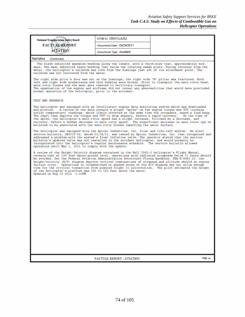
Aviation Safety Support Services for BSEE
Task C.4.5: Study on Effects of Combustible Gas on
Helicopter Operations
74 of 105

Aviation Safety Support Services for BSEE
Task C.4.5: Study on Effects of Combustible Gas on
Helicopter Operations
75 of 105

Aviation Safety Support Services for BSEE
Task C.4.5: Study on Effects of Combustible Gas on
Helicopter Operations
76 of 105

Aviation Safety Support Services for BSEE
Task C.4.5: Study on Effects of Combustible Gas on
Helicopter Operations
77 of 105
Aviation Safety Support Services for BSEE
Task C.4.5: Study on Effects of Combustible Gas on
Helicopter Operations
78 of 105

Aviation Safety Support Services for BSEE
Task C.4.5: Study on Effects of Combustible Gas on
Helicopter Operations
79 of 105
Appendix B-NTSB CEN13FA491 6.

Aviation Safety Support Services for BSEE
Task C.4.5: Study on Effects of Combustible Gas on
Helicopter Operations
80 of 105

Aviation Safety Support Services for BSEE
Task C.4.5: Study on Effects of Combustible Gas on
Helicopter Operations
81 of 105

Aviation Safety Support Services for BSEE
Task C.4.5: Study on Effects of Combustible Gas on
Helicopter Operations
82 of 105

Aviation Safety Support Services for BSEE
Task C.4.5: Study on Effects of Combustible Gas on
Helicopter Operations
83 of 105
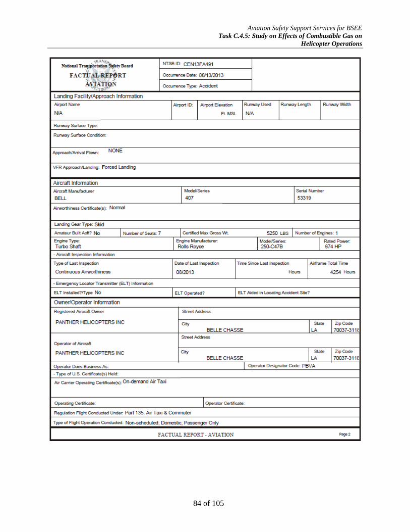
Aviation Safety Support Services for BSEE
Task C.4.5: Study on Effects of Combustible Gas on
Helicopter Operations
84 of 105

Aviation Safety Support Services for BSEE
Task C.4.5: Study on Effects of Combustible Gas on
Helicopter Operations
85 of 105
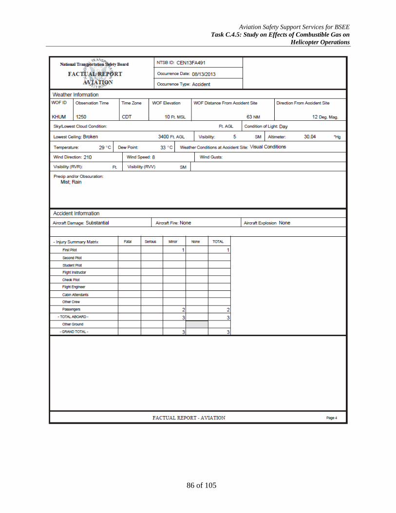
Aviation Safety Support Services for BSEE
Task C.4.5: Study on Effects of Combustible Gas on
Helicopter Operations
86 of 105
Aviation Safety Support Services for BSEE
Task C.4.5: Study on Effects of Combustible Gas on
Helicopter Operations
87 of 105
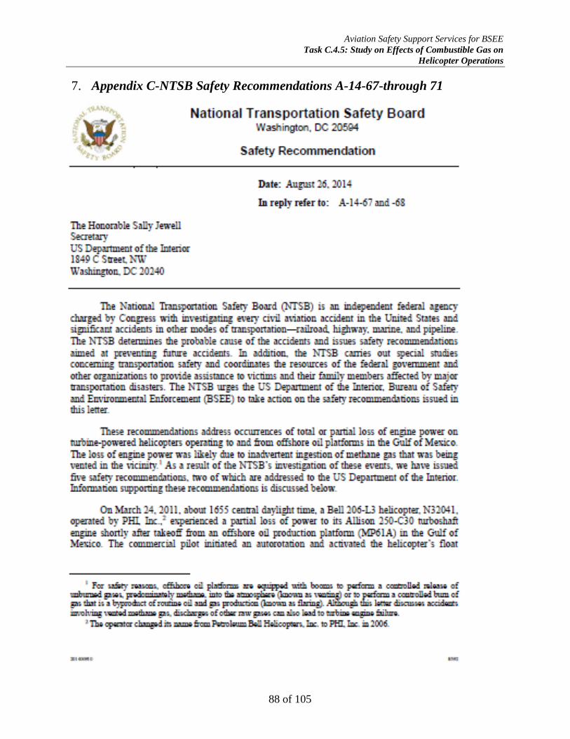
Aviation Safety Support Services for BSEE
Task C.4.5: Study on Effects of Combustible Gas on
Helicopter Operations
88 of 105
Appendix C-NTSB Safety Recommendations A-14-67-through 71 7.

Aviation Safety Support Services for BSEE
Task C.4.5: Study on Effects of Combustible Gas on
Helicopter Operations
89 of 105

Aviation Safety Support Services for BSEE
Task C.4.5: Study on Effects of Combustible Gas on
Helicopter Operations
90 of 105

Aviation Safety Support Services for BSEE
Task C.4.5: Study on Effects of Combustible Gas on
Helicopter Operations
91 of 105
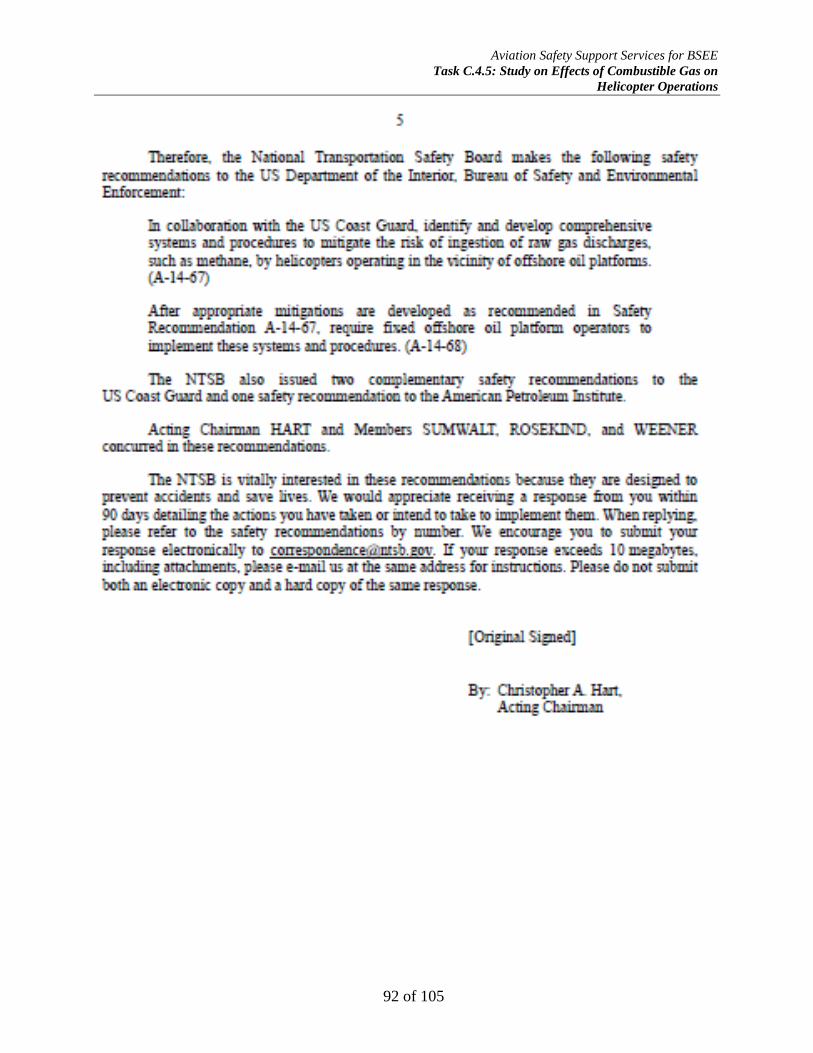
Aviation Safety Support Services for BSEE
Task C.4.5: Study on Effects of Combustible Gas on
Helicopter Operations
92 of 105

Aviation Safety Support Services for BSEE
Task C.4.5: Study on Effects of Combustible Gas on
Helicopter Operations
93 of 105

Aviation Safety Support Services for BSEE
Task C.4.5: Study on Effects of Combustible Gas on
Helicopter Operations
94 of 105

Aviation Safety Support Services for BSEE
Task C.4.5: Study on Effects of Combustible Gas on
Helicopter Operations
95 of 105
Aviation Safety Support Services for BSEE
Task C.4.5: Study on Effects of Combustible Gas on
Helicopter Operations
96 of 105

Aviation Safety Support Services for BSEE
Task C.4.5: Study on Effects of Combustible Gas on
Helicopter Operations
97 of 105
Aviation Safety Support Services for BSEE
Task C.4.5: Study on Effects of Combustible Gas on
Helicopter Operations
98 of 105
Aviation Safety Support Services for BSEE
Task C.4.5: Study on Effects of Combustible Gas on
Helicopter Operations
99 of 105
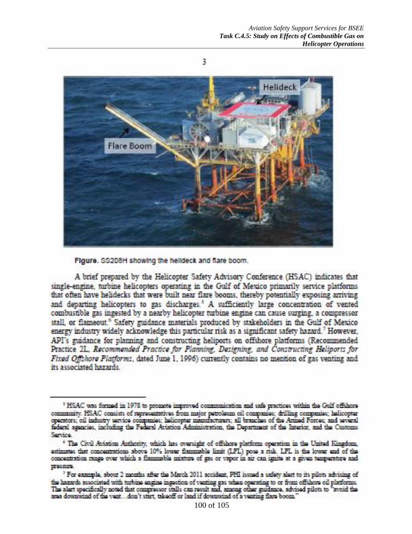
Aviation Safety Support Services for BSEE
Task C.4.5: Study on Effects of Combustible Gas on
Helicopter Operations
100 of 105

Aviation Safety Support Services for BSEE
Task C.4.5: Study on Effects of Combustible Gas on
Helicopter Operations
101 of 105

Aviation Safety Support Services for BSEE
Task C.4.5: Study on Effects of Combustible Gas on
Helicopter Operations
102 of 105
Appendix D-Representative OCS Platforms 8.
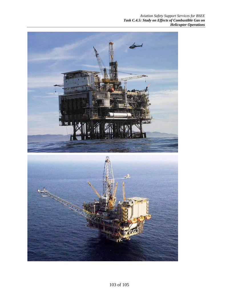
Aviation Safety Support Services for BSEE
Task C.4.5: Study on Effects of Combustible Gas on
Helicopter Operations
103 of 105

Aviation Safety Support Services for BSEE
Task C.4.5: Study on Effects of Combustible Gas on
Helicopter Operations
104 of 105
Appendix E – Helicopters Operating on the OCS 9.
Airframe Make Airframe Model Powerplant(s)
MGTOW
(lbs)
Range
(nm)
Capacity
(pilot/pax)
Airbus/Eurocopter AS350B3 Ecureuil/AStar 1 x Turbomeca Arriel 2B 4960 357 1/5
Airbus/Eurocopter EC120B Colibri 1 x Turbomeca Arrius 2F 3780 383 2/11
Airbus/Eurocopter EC130B4 1 x Turbomeca Arriel 2B 3036 329 1/4
AgustaWestland AW119Ke Koala 1 x PW PT6B-37A 6383 535 1/7
Bell Helicopter Textron 204B Iroquois (Huey) 1 x Lycoming T53-11A 9,500 300 2/8
Bell Helicopter Textron 205B Iroquois (Huey) 1 x Lycoming T53-13B 10,500 300 2/13
Bell Helicopter Textron 206B/B-2 JetRanger 1 x Allison 250-C20B 3,000 379 1/4
Bell Helicopter Textron 206B-3 JetRanger 1 x Allison 250-C20J 3,000 379 1/4
Bell Helicopter Textron 206L LongRanger 1 x Allison 250-C20B 4,150 339 1/6
Bell Helicopter Textron 206L-1 LongRanger II 1 x Allison 250-C28B 4,150 374 1/6
Bell Helicopter Textron 206L-3 LongRanger III 1 x Allision 250-C30P 4,150 360 1/6
Bell Helicopter Textron 206L-4 LongRanger IV 1 x Allision 250-C30P 4,450 374 1/4
Bell Helicopter Textron 407 1 x Allision 250-C47B 2,722 324 1/6
Bell Helicopter Textron 214A Huey Plus 1 x Lycoming LTC4B-8D 15,000 255 2/14
MD/Hughes MD500C 1 x Allision 250-C18B 2,550 325 1/4
MD/Hughes MD500D/E 1 x Allision 250-C20B 3,000 258 1/4
MD/Boeing MD500F/530F 1 x Allison 250-C30B 3,100 232 1/4
MD/Boeing MD520N NOTAR 1 x Rolls-Royce 250-C20R 3,350 229 1/4
MD/Boeing MD600N NOTAR 1 x Rolls-Royce 250-C47M 4,100 342 1/7
Robinson R66 1 x Rolls-Royce RR300 2,700 325 1/4
Airbus/Eurocopter AS355F2 Ecureuil 2/TwinStar 2 x Allision 250-C20F 5732 380 1/6
Airbus/Eurocopter AS355N Ecureuil 2/Twin Star 2 x Turbomeca Arrius 1A 5732 380 1/6
Airbus/Eurocopter AS355NP Ecureuil 2/Twin Star 2 x Turbomeca Arrius 1A 6173 380 1/6
Airbus/Eurocopter AS365N3 Dauphin 2 x Turbomeca Arriel 2C 9480 447 2/11
Airbus/Eurocopter EC135P1/P2 2 x PW206B 6250 343 1/7
Airbus/Eurocopter EC135T1/T2 2 x Turbomeca Arrius 2B 6250 343 1/7
Airbus/Eurocopter EC135P2+ 2 x PW206B 6415 343 1/7
Airbus/Eurocopter EC135T2+ 2 x Turbomeca Arrius 2B 6415 343 1/7
Airbus/Eurocopter EC135P3 2 x PW206B 6570 343 1/7
Airbus/Eurocopter EC135T3 2 x Turbomeca Arrius 2B+ 6570 343 1/7
Airbus/Eurocopter EC145 2 x Turbomeca Arriel 1E 7093 461 1/9
Airbus/Eurocopter EC145T2 2 x Turbomeca Arriel 2E 8047 356 1/9
Airbus/Eurocopter EC155B1 2 x Turbomeca Arriel 2C 10847 463 2/13
Airbus/Eurocopter EC225 Super Puma 2 x Turbomeca Makila 2A1 24,692 463 2/25
Agusta A109A 2 x Allision 250-C20B 5732 350 1/7
Agusta A109E 2 x PW206C 6283 528 1/7
AgustaWestland AW109 2 x PW206C 6283 503 1/7
AgustaWestland AW139 2 x PW PT6C-67C 14,110 675 2/15
Bell Helicopter Textron 212 Twin Huey 2 x PW PT6T-3B Twin-Pac 11,200 237 2/13
Bell Helicopter Textron 214ST 2 x GE CT7-2A 17,500 435 2/16
Bell Helicopter Textron 222B/U 2 x Lycoming LTS-101-750C 8,250 386 2/8
Bell Helicopter Textron 230 2 x Allison 250-C30G/2 8,400 378 2/8
Bell Helicopter Textron 412EP 2 x PW PT6T-3BE 11,900 402 2/13
Bell Helicopter Textron 427 2 x PW PW207D 6,550 394 1/7
Bell Helicopter Textron 429 GlobalRanger 2 x PW PW207D1 7,000 390 1/7
Bell Helicopter Textron 430 2 x Rolls-Royce 250-C40B 9,300 324 2/8
Eurocopter/Kawasaki MBB/BK-117B-2 2 x Lycoming LTS-101-750B-1 7,385 336 1/9
MBB Bo105CB 2 x Allison 250-C20B 5,511 310 1/7
Sikorsky S-76A 2 x Allison 250-C30S 10,500 380 2/12
Sikorsky S-76A+/A++ 2 x Turbomeca Arriel 1S1 10,500 2/12
Sikorsky S-76B 2 x PW PT6B-36A 11,700 2/12
Sikorsky S-76C 2 x Turbomeca Arriel 2S 11,700 2/12
Sikorsky S-76C+ 2 x Turbomeca Arriel 2S1 11,700 439 2/12
Sikorsky S-76C++ 2 x Turbomeca Arriel 2S2 11,700 411 2/12
Sikorsky S-76D 2 x PW210S 11,700 2/12
Sikorsky S-92A Helibus 2 x GE CT7-8A 15,900 726 2/19

Aviation Safety Support Services for BSEE
Task C.4.5: Study on Effects of Combustible Gas on
Helicopter Operations
105 of 105
Appendix F-Preliminary Engineering Analysis Report-(attached as separate 10.
document)