Embed Size (px)
Citation preview

Model year: 2006
Vehicle code: **T25*R-*****W
Part number: • Navigation System 08545-00950• Audio Frame 55405-05160
Manual ref. no: AIM 001 067-0
AvensisTNS700RHD installation instructions
Avensis (T25) TNS 700
Avensis (RHD) - 201-07
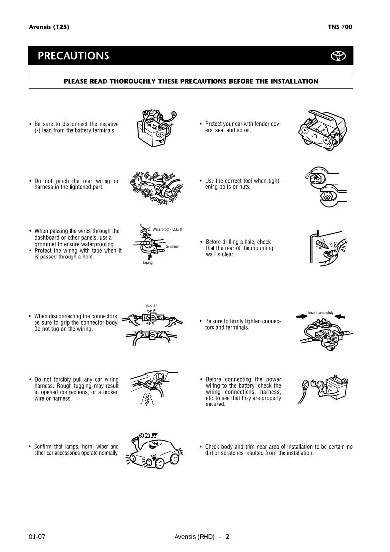
PRECAUTIONS
• Do not pinch the rear wiring or harness in the tightened part.
PLEASE READ THOROUGHLY THESE PRECAUTIONS BEFORE THE INSTALLATION
• Be sure to disconnect the negative (-) lead from the battery terminals.
• When passing the wires through thedashboard or other panels, use agrommet to ensure waterproofing.
• Protect the wiring with tape when it is passed through a hole.
• When disconnecting the connectors,be sure to grip the connector body.Do not tug on the wiring.
• Do not forcibly pull any car wiringharness. Rough tugging may resultin opened connections, or a brokenwire or harness.
• Confirm that lamps, horn, wiper andother car accessories operate normally.
• Protect your car with fender cov-ers, seat and so on.
• Use the correct tool when tight-ening bolts or nuts.
• Before drilling a hole, checkthat the rear of the mountingwall is clear.
• Be sure to firmly tighten connec-tors and terminals.
• Before connecting the powerwiring to the battery, check thewiring connections, harness,etc. to see that they are properlysecured.
• Check body and trim near area of installation to be certain nodirt or scratches resulted from the installation.
Stop it !
Waterproof - O.K. !!
Grommet
Taping
Insert completely
Avensis (T25) TNS 700
Avensis (RHD) - 3 01-07
Precautions ............................................................................................................................................. 2
Component parts ................................................................................................................................... 4
Navigation Kit ........................................................................................................................................ 5
How to connect ..................................................................................................................................... 6
Installation Overview .............................................................................................................................. 7
Vehicle Disassembly ................................................................................................................................ 8
Installation of the GPS-Antenna .............................................................................................................. 10
Wire Harness Installation ......................................................................................................................... 12
Installation of the Navigation Disc .......................................................................................................... 17
Post-Installation Inspection ..................................................................................................................... 17
Reassembling ......................................................................................................................................... 17
Be sure to read the General Installation Instructions (Common Section) before installing TNS 700.
REMARK
TABLE OF CONTENTS
Avensis (T25) TNS 600
Avensis (RHD) - 401-07
Avensis (T25) TNS 700
AUDIO DISPLAY TILT OPEN
MENU
SEEKTRACK
DEST
MAPVOICE
DISC
TUNEVOICE NAVIGATIONPWR•VOL
TA
INFO
FM
AM
B-9001TOYOTA
1 2 3
4 6
7 8
5
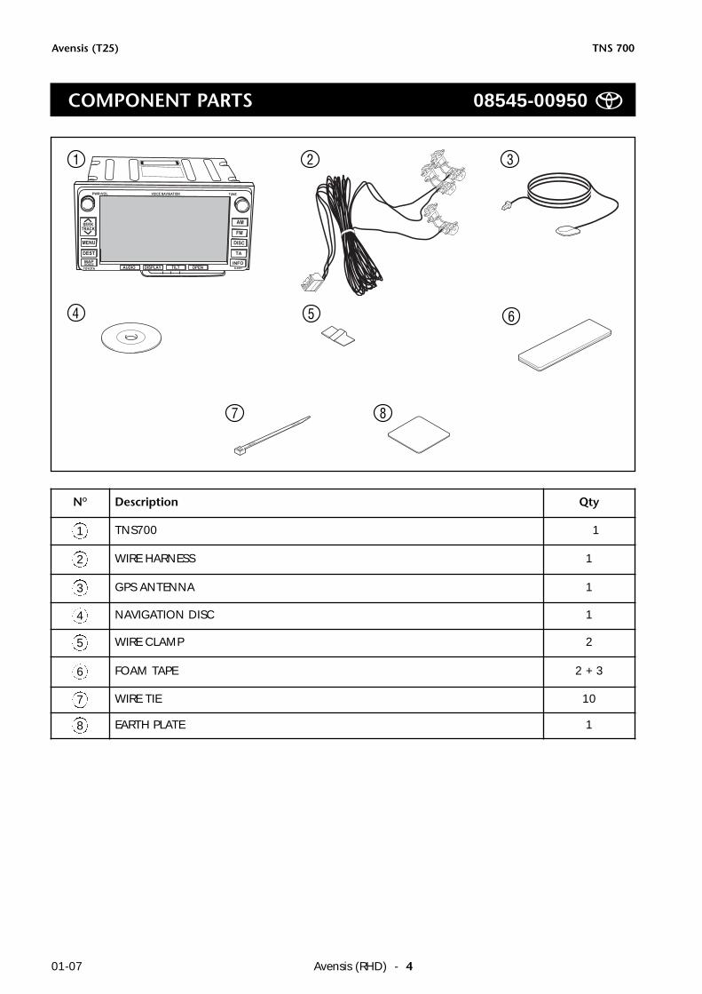
NO Description Qty
1 TNS700 1
2 WIRE HARNESS 1
3 GPS ANTENNA 1
4 NAVIGATION DISC 1
5 WIRE CLAMP 2
6 FOAM TAPE 2 + 3
7 WIRE TIE 10
8 EARTH PLATE 1
COMPONENT PARTS 08545-00950
Avensis (T25) TNS 600
Avensis (RHD) - 5 01-07
Avensis (T25) TNS 700
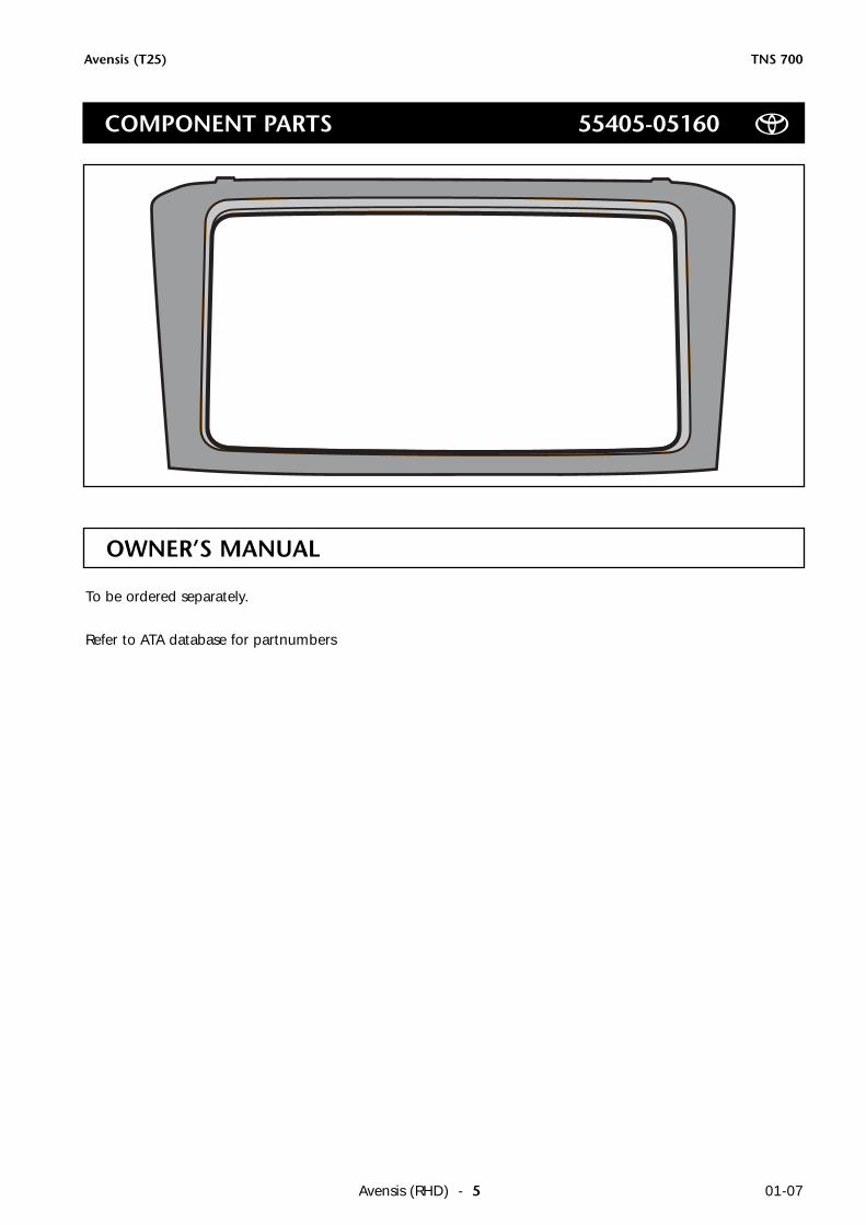
OWNER’S MANUAL
To be ordered separately.
Refer to ATA database for partnumbers
COMPONENT PARTS 55405-05160
Avensis (T25) TNS00
Avensis (RHD) - 601-07
Avensis (T25) TNS 700
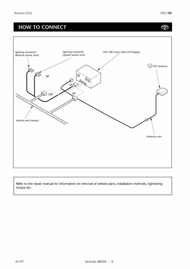
Refer to the repair manual for information on removal of vehicle parts, installation methods, tighteningtorque etc.
Vehicle wire harness
Splicing connector(Reverse sensor wire)
Antenna wire
GPS antenna3
5P
TNS 700 Tuner with LCD Display
8P
10P 6P
Splicing connector(Speed sensor wire)
HOW TO CONNECT
Avensis (T25) TNS 700
Avensis (RHD) - 7 01-07
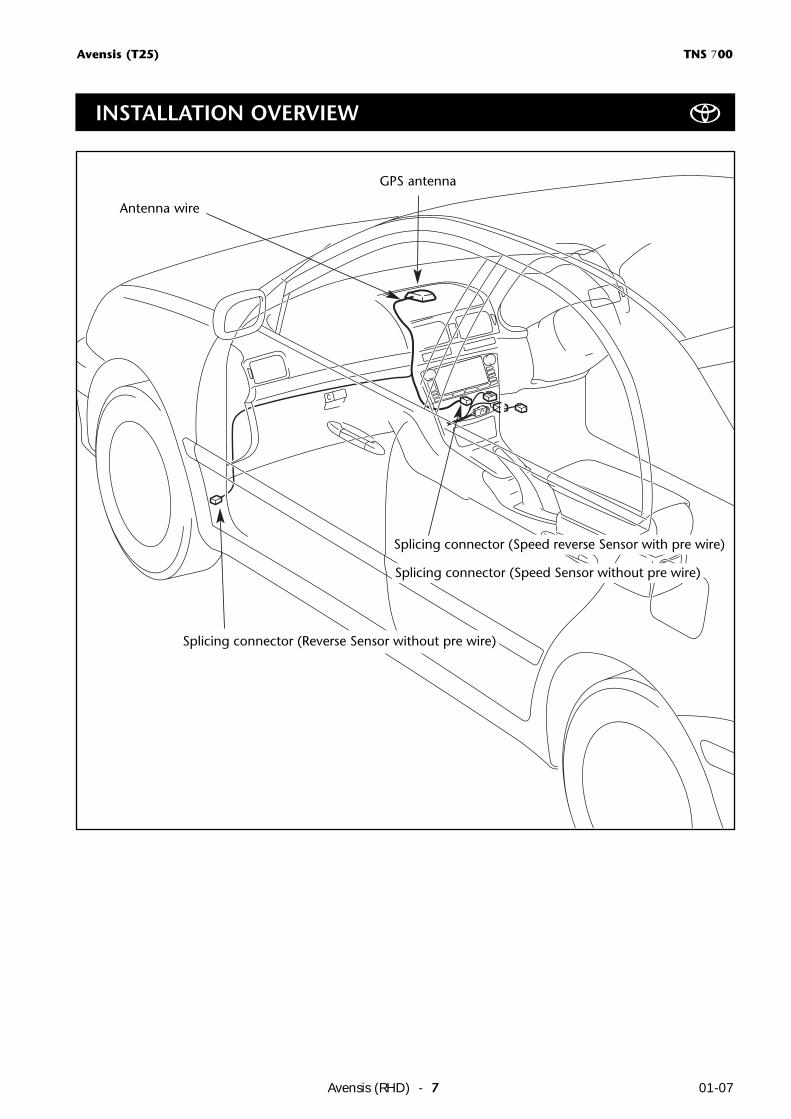
GPS antenna
Antenna wire
Splicing connector (Speed reverse Sensor with pre wire)
Splicing connector (Reverse Sensor without pre wire)
Splicing connector (Speed Sensor without pre wire)
INSTALLATION OVERVIEW
Avensis (T25) TNS 700
Avensis (RHD) - 801-07
1
2
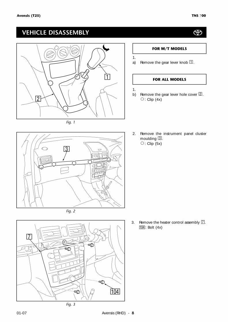
1.a) Remove the gear lever knob .
1.b) Remove the gear lever hole cover .
: Clip (4x)2
1
FOR M/T MODELS
Fig. 2
Fig. 1
3
2. Remove the instrument panel clustermoulding .
: Clip (5x)3
FOR ALL MODELS
Fig. 3
3. Remove the heater control assembly .: Bolt (4x)104
7
7
104
VEHICLE DISASSEMBLY
Avensis (T25) TNS 700
Avensis (RHD) - 9 01-07
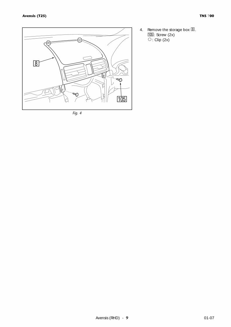
Fig. 4
4. Remove the storage box .: Screw (2x)
: Clip (2x)105
8
8
105
Avensis (T25) TNS 700
Avensis (RHD) - 1001-07
Fig. 5
12x
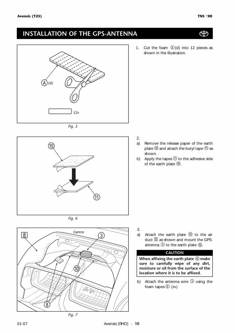
1. Cut the foam (d) into 12 pieces asshown in the illustration.
A
A (d)
Fig. 6
2.a) Remove the release paper of the earth
plate and attach the butyl tape asshown.
b) Apply the tapes to the adhesive sideof the earth plate .10
11
1110
11
10
INSTALLATION OF THE GPS-ANTENNA
3.a) Attach the earth plate to the air
duct as shown and mount the GPS-antenna to the earth plate .
b) Attach the antenna wire using thefoam tapes (3x).8
3
103
810
Fig. 7
8
8 3
10
Centre
When affixing the earth plate makesure to carefully wipe of any dirt,moisture or oil from the surface of thelocation where it is to be affixed.
10
CAUTION
Avensis (T25) TNS 700
Avensis (RHD) - 11 01-07
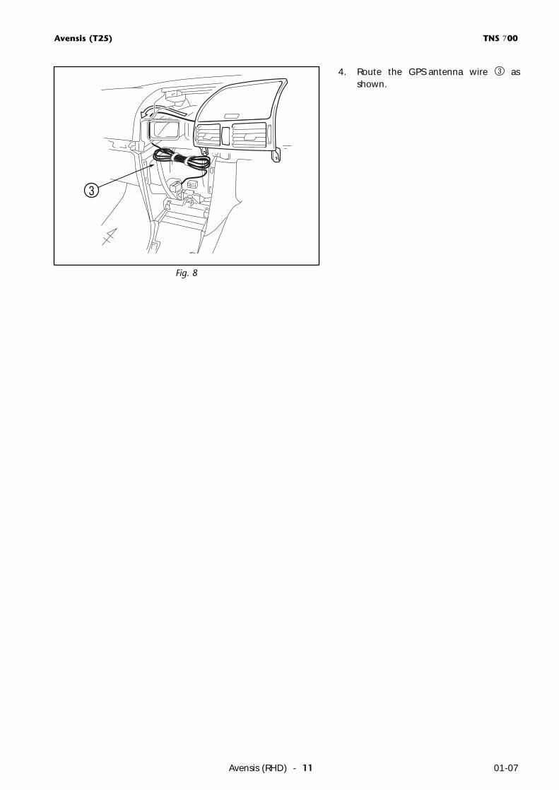
Fig. 8
4. Route the GPS antenna wire asshown.
3
3
Avensis (T25) TNS 700
Avensis (RHD) - 1201-07
Pliers
Splicing connector
Vehicle wire harness
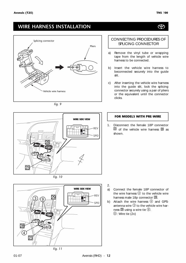
Fig. 9
a) Remove the vinyl tube or wrappingtape from the length of vehicle wireharness to be connected.
b) Insert the vehicle wire harness tobeconnected securely into the guideslit.
c) After inserting the vehicle wire harnessinto the guide slit, lock the splicingconnector securely using a pair of pliersor the equivalent until the connectorclicks.
CONNECTING PROCEDURES OFSPLICING CONNECTOR
Fig. 10
Fig. 11
WIRE SIDE VIEW
23
1. Disconnect the female 18P connectorof the vehicle wire harness as
shown.2823
3
28
29
28
WIRE SIDE VIEW
FOR MODELS WITH PRE-WIRE
234
9
WIRE HARNESS INSTALLATION
2.a) Connect the female 18P connector of
the wire harness to the vehicle wireharness male 18p connector .
b) Attach the wire harness and GPS-antenna wire to the vehicle wire har-ness using a wire tie .
: Wire tie (2x)9
9293
4
284
Avensis (T25) TNS 700
Avensis (RHD) - 13 01-07
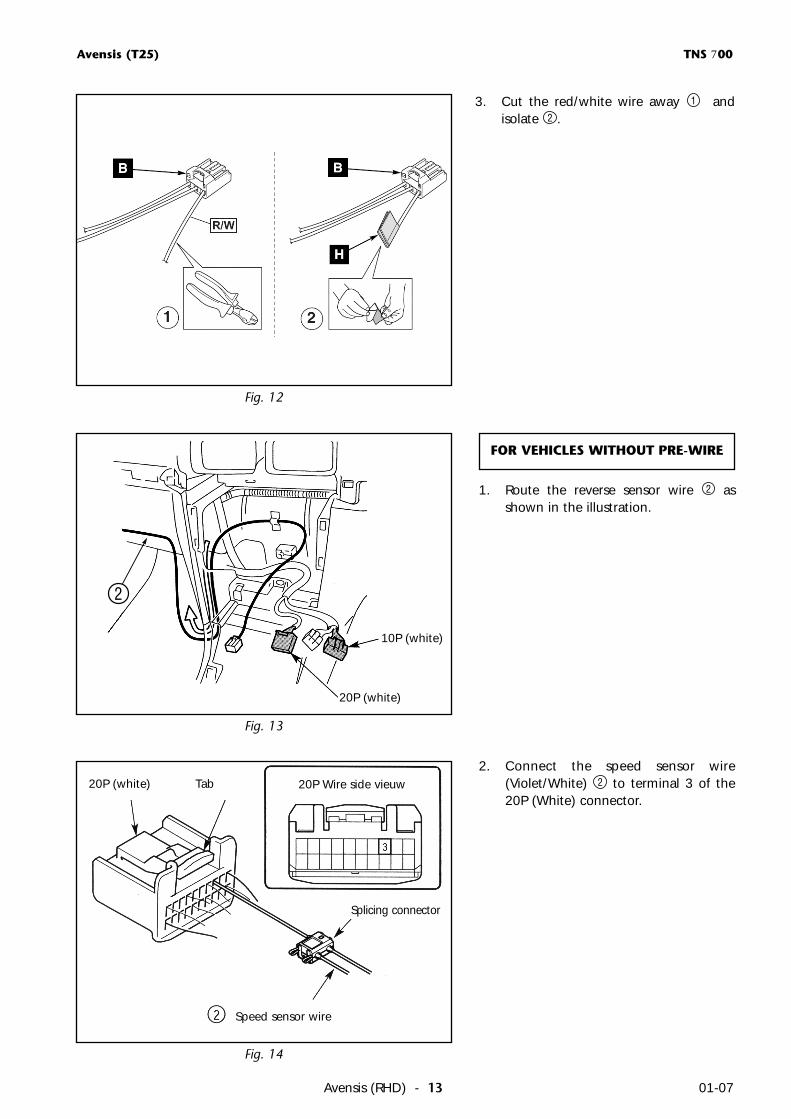
3. Cut the red/white wire away andisolate .2
1
Fig. 12
FOR VEHICLES WITHOUT PRE-WIRE
Fig. 13
1. Route the reverse sensor wire asshown in the illustration.
2
20P (white)
10P (white)
2
Fig. 14
2. Connect the speed sensor wire(Violet/White) to terminal 3 of the20P (White) connector.
220P (white) Tab
Splicing connector
Speed sensor wire
20P Wire side vieuw
Avensis (T25) TNS 700
Avensis (RHD) - 1401-07
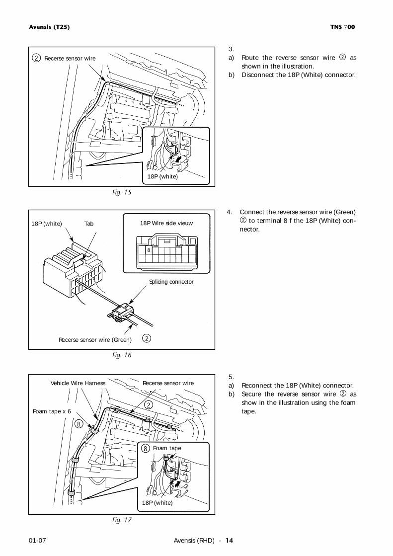
Fig. 15
3.a) Route the reverse sensor wire as
shown in the illustration.b) Disconnect the 18P (White) connector.
2
Fig. 17
Fig. 16
4. Connect the reverse sensor wire (Green)to terminal 8 f the 18P (White) con-
nector.2
5.a) Reconnect the 18P (White) connector.b) Secure the reverse sensor wire as
show in the illustration using the foamtape.
2
Recerse sensor wire
18P (white) Tab
Splicing connector
18P Wire side vieuw
Foam tape x 6
Recerse sensor wire (Green)
Vehicle Wire Harness Recerse sensor wire
Foam tape
18P (white)
18P (white)
Avensis (T25) TNS 700
Avensis (RHD) - 15 01-07
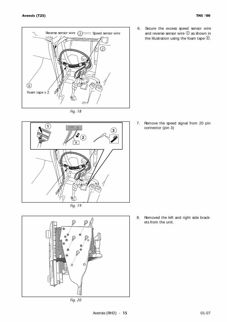
Fig. 18
6. Secure the excess speed sensor wireand reverse sensor wire as shown inthe illustration using the foam tape .8
2
Foam tape x 2
Speed sensor wireRecerse sensor wire
7. Remove the speed signal from 20 pinconnector (pin 3)
Fig. 19
R
8. Removed the left and right side brack-ets from the unit.
Fig. 20
Avensis (T25) TNS 700
Avensis (RHD) - 1601-07
MODE
AUTO DUAL
A/C OFF
TEMPTEMP
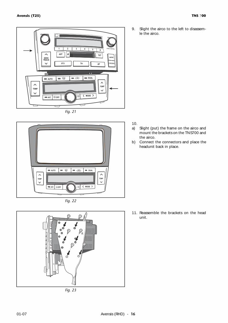
10.a) Slight (put) the frame on the airco and
mount the brackets on the TNS700 andthe airco.
b) Connect the connectors and place theheadunit back in place.
Fig. 22
R
11. Reassemble the brackets on the headunit.
Fig. 23
PWR•VOL
AM/FM
TUNER
AUDIO CONTROL
SEEKTRACK
AST
PTY TA AF
TXT
1 2 3 4 5 6
TAPE/DISC
TEMP
AUTO DUAL
A/CMODE
OFF
TEMP
Fig. 21
9. Slight the airco to the left to disassem-le the airco.
Avensis (T25) TNS 700
Avensis (RHD) - 17 01-07
MODE
AUTO DUAL
A/C OFF
TEMP
AUDIO DISPLAY TILT OPEN
MENU
SEEKTRACK
DEST
MAPVOICE
DISC
TUNEVOICE NAVIGATIONPWR•VOL
TA
INFO
FM
AM
B-9001TOYOTA
TEMP
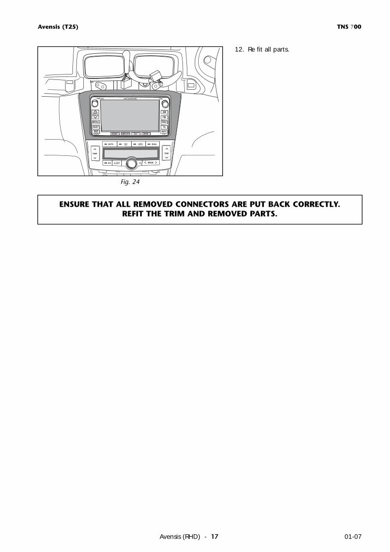
12. Re fit all parts.
Fig. 24
ENSURE THAT ALL REMOVED CONNECTORS ARE PUT BACK CORRECTLY.REFIT THE TRIM AND REMOVED PARTS.
Avensis (T25) TNS 700
Avensis (RHD) - 1801-07
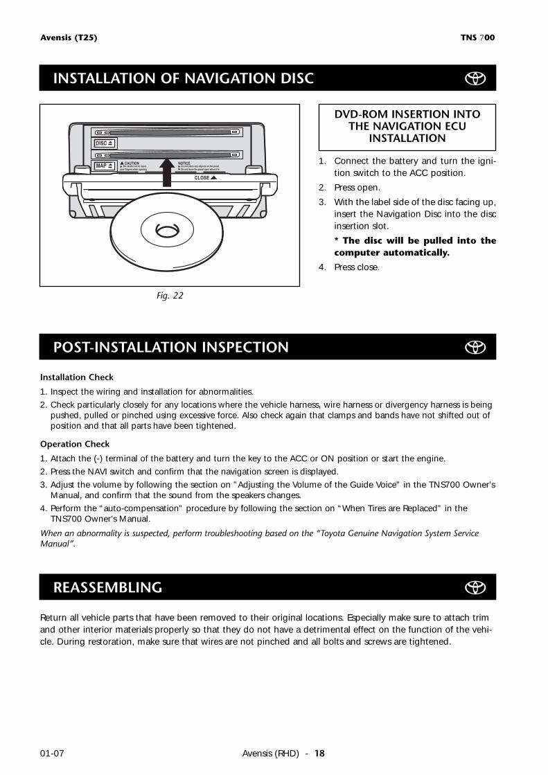
Fig. 22
MAP
DISC
CAUTION NOTICE
CLOSE
Be careful not to injureyour fingers when opening
Do not place any objects on the panelDo not leave the panel open when it is
DVD-ROM INSERTION INTOTHE NAVIGATION ECU
INSTALLATION
1. Connect the battery and turn the igni-tion switch to the ACC position.
2. Press open.
3. With the label side of the disc facing up,insert the Navigation Disc into the discinsertion slot.
* The disc will be pulled into thecomputer automatically.
4. Press close.
INSTALLATION OF NAVIGATION DISC
Installation Check
1. Inspect the wiring and installation for abnormalities.
2. Check particularly closely for any locations where the vehicle harness, wire harness or divergency harness is beingpushed, pulled or pinched using excessive force. Also check again that clamps and bands have not shifted out ofposition and that all parts have been tightened.
Operation Check
1. Attach the (-) terminal of the battery and turn the key to the ACC or ON position or start the engine.
2. Press the NAVI switch and confirm that the navigation screen is displayed.
3. Adjust the volume by following the section on ”Adjusting the Volume of the Guide Voice” in the TNS700 Owner’sManual, and confirm that the sound from the speakers changes.
4. Perform the “auto-compensation” procedure by following the section on “When Tires are Replaced” in theTNS700 Owner’s Manual.
When an abnormality is suspected, perform troubleshooting based on the “Toyota Genuine Navigation System ServiceManual”.
POST-INSTALLATION INSPECTION
Return all vehicle parts that have been removed to their original locations. Especially make sure to attach trimand other interior materials properly so that they do not have a detrimental effect on the function of the vehi-cle. During restoration, make sure that wires are not pinched and all bolts and screws are tightened.
REASSEMBLING

GENUINE PARTS